US8585709B2 - Straight cup impactor with lever arm - Google Patents
Straight cup impactor with lever armDownload PDFInfo
- Publication number
- US8585709B2 US8585709B2US13/351,302US201213351302AUS8585709B2US 8585709 B2US8585709 B2US 8585709B2US 201213351302 AUS201213351302 AUS 201213351302AUS 8585709 B2US8585709 B2US 8585709B2
- Authority
- US
- United States
- Prior art keywords
- distal
- proximal
- rod
- lever arm
- impactor
- Prior art date
- Legal status (The legal status is an assumption and is not a legal conclusion. Google has not performed a legal analysis and makes no representation as to the accuracy of the status listed.)
- Active, expires
Links
Images


Classifications
- A—HUMAN NECESSITIES
- A61—MEDICAL OR VETERINARY SCIENCE; HYGIENE
- A61F—FILTERS IMPLANTABLE INTO BLOOD VESSELS; PROSTHESES; DEVICES PROVIDING PATENCY TO, OR PREVENTING COLLAPSING OF, TUBULAR STRUCTURES OF THE BODY, e.g. STENTS; ORTHOPAEDIC, NURSING OR CONTRACEPTIVE DEVICES; FOMENTATION; TREATMENT OR PROTECTION OF EYES OR EARS; BANDAGES, DRESSINGS OR ABSORBENT PADS; FIRST-AID KITS
- A61F2/00—Filters implantable into blood vessels; Prostheses, i.e. artificial substitutes or replacements for parts of the body; Appliances for connecting them with the body; Devices providing patency to, or preventing collapsing of, tubular structures of the body, e.g. stents
- A61F2/02—Prostheses implantable into the body
- A61F2/30—Joints
- A61F2/46—Special tools for implanting artificial joints
- A61F2/4603—Special tools for implanting artificial joints for insertion or extraction of endoprosthetic joints or of accessories thereof
- A61F2/4609—Special tools for implanting artificial joints for insertion or extraction of endoprosthetic joints or of accessories thereof of acetabular cups
- A—HUMAN NECESSITIES
- A61—MEDICAL OR VETERINARY SCIENCE; HYGIENE
- A61F—FILTERS IMPLANTABLE INTO BLOOD VESSELS; PROSTHESES; DEVICES PROVIDING PATENCY TO, OR PREVENTING COLLAPSING OF, TUBULAR STRUCTURES OF THE BODY, e.g. STENTS; ORTHOPAEDIC, NURSING OR CONTRACEPTIVE DEVICES; FOMENTATION; TREATMENT OR PROTECTION OF EYES OR EARS; BANDAGES, DRESSINGS OR ABSORBENT PADS; FIRST-AID KITS
- A61F2/00—Filters implantable into blood vessels; Prostheses, i.e. artificial substitutes or replacements for parts of the body; Appliances for connecting them with the body; Devices providing patency to, or preventing collapsing of, tubular structures of the body, e.g. stents
- A61F2/02—Prostheses implantable into the body
- A61F2/30—Joints
- A61F2/32—Joints for the hip
- A61F2/34—Acetabular cups
- A—HUMAN NECESSITIES
- A61—MEDICAL OR VETERINARY SCIENCE; HYGIENE
- A61F—FILTERS IMPLANTABLE INTO BLOOD VESSELS; PROSTHESES; DEVICES PROVIDING PATENCY TO, OR PREVENTING COLLAPSING OF, TUBULAR STRUCTURES OF THE BODY, e.g. STENTS; ORTHOPAEDIC, NURSING OR CONTRACEPTIVE DEVICES; FOMENTATION; TREATMENT OR PROTECTION OF EYES OR EARS; BANDAGES, DRESSINGS OR ABSORBENT PADS; FIRST-AID KITS
- A61F2/00—Filters implantable into blood vessels; Prostheses, i.e. artificial substitutes or replacements for parts of the body; Appliances for connecting them with the body; Devices providing patency to, or preventing collapsing of, tubular structures of the body, e.g. stents
- A61F2/02—Prostheses implantable into the body
- A61F2/30—Joints
- A61F2002/30001—Additional features of subject-matter classified in A61F2/28, A61F2/30 and subgroups thereof
- A61F2002/30316—The prosthesis having different structural features at different locations within the same prosthesis; Connections between prosthetic parts; Special structural features of bone or joint prostheses not otherwise provided for
- A61F2002/30329—Connections or couplings between prosthetic parts, e.g. between modular parts; Connecting elements
- A61F2002/30476—Connections or couplings between prosthetic parts, e.g. between modular parts; Connecting elements locked by an additional locking mechanism
- A61F2002/30505—Connections or couplings between prosthetic parts, e.g. between modular parts; Connecting elements locked by an additional locking mechanism spring biased
- A—HUMAN NECESSITIES
- A61—MEDICAL OR VETERINARY SCIENCE; HYGIENE
- A61F—FILTERS IMPLANTABLE INTO BLOOD VESSELS; PROSTHESES; DEVICES PROVIDING PATENCY TO, OR PREVENTING COLLAPSING OF, TUBULAR STRUCTURES OF THE BODY, e.g. STENTS; ORTHOPAEDIC, NURSING OR CONTRACEPTIVE DEVICES; FOMENTATION; TREATMENT OR PROTECTION OF EYES OR EARS; BANDAGES, DRESSINGS OR ABSORBENT PADS; FIRST-AID KITS
- A61F2/00—Filters implantable into blood vessels; Prostheses, i.e. artificial substitutes or replacements for parts of the body; Appliances for connecting them with the body; Devices providing patency to, or preventing collapsing of, tubular structures of the body, e.g. stents
- A61F2/02—Prostheses implantable into the body
- A61F2/30—Joints
- A61F2/32—Joints for the hip
- A61F2/34—Acetabular cups
- A61F2002/3401—Acetabular cups with radial apertures, e.g. radial bores for receiving fixation screws
- A61F2002/3403—Polar aperture
- A—HUMAN NECESSITIES
- A61—MEDICAL OR VETERINARY SCIENCE; HYGIENE
- A61F—FILTERS IMPLANTABLE INTO BLOOD VESSELS; PROSTHESES; DEVICES PROVIDING PATENCY TO, OR PREVENTING COLLAPSING OF, TUBULAR STRUCTURES OF THE BODY, e.g. STENTS; ORTHOPAEDIC, NURSING OR CONTRACEPTIVE DEVICES; FOMENTATION; TREATMENT OR PROTECTION OF EYES OR EARS; BANDAGES, DRESSINGS OR ABSORBENT PADS; FIRST-AID KITS
- A61F2/00—Filters implantable into blood vessels; Prostheses, i.e. artificial substitutes or replacements for parts of the body; Appliances for connecting them with the body; Devices providing patency to, or preventing collapsing of, tubular structures of the body, e.g. stents
- A61F2/02—Prostheses implantable into the body
- A61F2/30—Joints
- A61F2/46—Special tools for implanting artificial joints
- A61F2/4603—Special tools for implanting artificial joints for insertion or extraction of endoprosthetic joints or of accessories thereof
- A61F2002/4625—Special tools for implanting artificial joints for insertion or extraction of endoprosthetic joints or of accessories thereof with relative movement between parts of the instrument during use
- A61F2002/4627—Special tools for implanting artificial joints for insertion or extraction of endoprosthetic joints or of accessories thereof with relative movement between parts of the instrument during use with linear motion along or rotating motion about the instrument axis or the implantation direction, e.g. telescopic, along a guiding rod, screwing inside the instrument
- A—HUMAN NECESSITIES
- A61—MEDICAL OR VETERINARY SCIENCE; HYGIENE
- A61F—FILTERS IMPLANTABLE INTO BLOOD VESSELS; PROSTHESES; DEVICES PROVIDING PATENCY TO, OR PREVENTING COLLAPSING OF, TUBULAR STRUCTURES OF THE BODY, e.g. STENTS; ORTHOPAEDIC, NURSING OR CONTRACEPTIVE DEVICES; FOMENTATION; TREATMENT OR PROTECTION OF EYES OR EARS; BANDAGES, DRESSINGS OR ABSORBENT PADS; FIRST-AID KITS
- A61F2/00—Filters implantable into blood vessels; Prostheses, i.e. artificial substitutes or replacements for parts of the body; Appliances for connecting them with the body; Devices providing patency to, or preventing collapsing of, tubular structures of the body, e.g. stents
- A61F2/02—Prostheses implantable into the body
- A61F2/30—Joints
- A61F2/46—Special tools for implanting artificial joints
- A61F2/4603—Special tools for implanting artificial joints for insertion or extraction of endoprosthetic joints or of accessories thereof
- A61F2002/4625—Special tools for implanting artificial joints for insertion or extraction of endoprosthetic joints or of accessories thereof with relative movement between parts of the instrument during use
- A61F2002/4628—Special tools for implanting artificial joints for insertion or extraction of endoprosthetic joints or of accessories thereof with relative movement between parts of the instrument during use with linear motion along or rotating motion about an axis transverse to the instrument axis or to the implantation direction, e.g. clamping
- A—HUMAN NECESSITIES
- A61—MEDICAL OR VETERINARY SCIENCE; HYGIENE
- A61F—FILTERS IMPLANTABLE INTO BLOOD VESSELS; PROSTHESES; DEVICES PROVIDING PATENCY TO, OR PREVENTING COLLAPSING OF, TUBULAR STRUCTURES OF THE BODY, e.g. STENTS; ORTHOPAEDIC, NURSING OR CONTRACEPTIVE DEVICES; FOMENTATION; TREATMENT OR PROTECTION OF EYES OR EARS; BANDAGES, DRESSINGS OR ABSORBENT PADS; FIRST-AID KITS
- A61F2/00—Filters implantable into blood vessels; Prostheses, i.e. artificial substitutes or replacements for parts of the body; Appliances for connecting them with the body; Devices providing patency to, or preventing collapsing of, tubular structures of the body, e.g. stents
- A61F2/02—Prostheses implantable into the body
- A61F2/30—Joints
- A61F2/46—Special tools for implanting artificial joints
- A61F2/4603—Special tools for implanting artificial joints for insertion or extraction of endoprosthetic joints or of accessories thereof
- A61F2002/4629—Special tools for implanting artificial joints for insertion or extraction of endoprosthetic joints or of accessories thereof connected to the endoprosthesis or implant via a threaded connection
- A—HUMAN NECESSITIES
- A61—MEDICAL OR VETERINARY SCIENCE; HYGIENE
- A61F—FILTERS IMPLANTABLE INTO BLOOD VESSELS; PROSTHESES; DEVICES PROVIDING PATENCY TO, OR PREVENTING COLLAPSING OF, TUBULAR STRUCTURES OF THE BODY, e.g. STENTS; ORTHOPAEDIC, NURSING OR CONTRACEPTIVE DEVICES; FOMENTATION; TREATMENT OR PROTECTION OF EYES OR EARS; BANDAGES, DRESSINGS OR ABSORBENT PADS; FIRST-AID KITS
- A61F2/00—Filters implantable into blood vessels; Prostheses, i.e. artificial substitutes or replacements for parts of the body; Appliances for connecting them with the body; Devices providing patency to, or preventing collapsing of, tubular structures of the body, e.g. stents
- A61F2/02—Prostheses implantable into the body
- A61F2/30—Joints
- A61F2/46—Special tools for implanting artificial joints
- A61F2002/4681—Special tools for implanting artificial joints by applying mechanical shocks, e.g. by hammering
Definitions
- the inventionrelates to surgical tools for aiding a surgeon installing an orthopedic prosthesis. More specifically, the invention relates to an orthopedic cup impactor for positioning an acetabular cup prosthesis within the body.
- a total hip replacementis a reconstructive surgical procedure typically performed by an orthopedic surgeon.
- a total hip replacementinvolves the placement of an acetabular cup within, a patient's acetabular socket, and the replacement of the patient's femoral neck with a prosthesis which terminates in a ball specifically designed to be positioned in the acetabular cup.
- Other surgical proceduresmay require the application of an acetabular cup or other device applied to a patient.
- the patient's acetabular socketis reamed out by the surgeon so as to create an enlarged recess to receive the acetabular cup.
- the cupis inserted into the recess and adjusted as necessary to the proper angular orientation. Once deployed, the cup provides a new socket and lining for the patient's acetabulum.
- Insertion and placement of the cup by the surgeonis effected either by hand or by use of a hand tool that grips the cup.
- the cupcan be fixed in the desired location by various means such as bone screws, medically acceptable adhesives, or combinations thereof.
- the fixation meansinclude passing bone screws through the cup and into pre-drilled screw holes in the pelvic bone.
- the bone screwswhich are optional, serve to hold the acetabular cup in the acetabulum until bone ingrowth provides permanent fixation.
- the cupis properly positioned in the acetabulum by implantation.
- One conventional implantation methodis, after obtaining proper alignment, to impact an acetabular cup into place. While impacting the acetabular cup, the surgeon listens for a change in pitch as the cup seats down. The surgeon then probes screw holes to determine if a gap between the cup and the bone is present. If a gap is present, the surgeon further impacts the cup into the acetabulum.
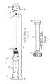
- FIGS. 1 and 2illustrate a conventional spindle-type orthopedic surgical impactor 10 .
- this prior art impactor 10has a strike plate 12 that is integrally connected to a proximal end 16 of the impactor body 14 . Extending from the strike plate 12 and positioned over a proximal area of the body portion 14 is a fixed handle 18 .
- the fixed handle 18has a length that allows a surgeon to hold the impactor 10 , in one embodiment with one hand, and in an alternative embodiment with two hands.
- an impactor thread section 20is an impactor thread section 20 .
- a tool thread section 24is an impactor thread section 22 .
- the tool thread section 24threadingly interconnects to a surgical implant device (a.k.a., medical attachment) 26 , for example, and not limited to, an acetabular cup, through a threaded aperture 28 ( FIG. 2 ). That means the implant device 26 is directly connected to the body 14 and the strike plate 12 . To ensure the surgical implant device 26 is properly secured to the tool thread section 24 , the prior art device 10 uses rotate handle device 30 ( FIG. 2A ).
- a surgical implant devicea.k.a., medical attachment
- the rotate handle 30is positioned in the spacing between the tool thread section 24 and the impactor thread section 20 .
- the rotate handle device 30At its proximal end, the rotate handle device 30 has a rotating threaded section 32 and at its distal end, an implant support 34 .
- the rotating threaded section 32has threads that mate with the impactor thread section 20 .
- the rotating threaded section 32When the rotating threaded section 32 is rotated clockwise (illustrated by arrow 36 at FIG. 1 ), (a) the rotating threaded section 32 pushes (illustrated by arrow 38 ) the rotate handle 30 and the implant support surface 34 toward the surgical implant device's interior surface 40 ( FIG.
- the rotating threaded section 32through a conventional lock-nut structure, rotates the surgical implant device 26 counter-clockwise (arrow 42 at FIG. 1 ). This movement results in the surgical implant 26 being pushed toward the implant support 34 .
- the clock-wise rotating threaded section 32is designed to securely position the surgical implant 26 against the implant support 34 to inhibit dislodging of the surgical implant device 26 from the spindle-type tool holder 10 when the surgeon impacts the tool holder.
- the cup impactor of the present inventioncomprises an elongated body with respective distal and proximal ends.
- the elongated bodyis constructed with a strike plate residing at the body's proximal end, and an impactor cup engagement portion located at the body's opposing distal end.
- the elongated bodyis constructed of a one-piece design.
- the elongated bodyis designed such that the strike plate fluidly extends from the proximal end portion through a body length portion to the impactor cup engagement portion at the distal end portion.
- connection rodhaving respective proximal and distal rod ends, is positioned within an elongated cavity of the body.
- the distal end of the connection rodis constructed with a threaded end that is designed to threadably attach to a threaded aperture of a prosthetic orthopedic cup.
- the proximal end portion of the connection rodresides within the body cavity such that the rod's proximal end does not contact the inside wall surface of the body.
- the proximal end portionis connected to a ring that circumferentially extends around an exterior surface of the annular sidewall of the body.
- the ringis designed such that it is in a slidable relationship along the elongated body.
- a rod connection pinextends perpendicularly through the proximal end of the connection rod.
- the opposing rod endsare positioned such that they extend through opposing slots of the annular sidewall of the body, connecting with the ring's annular sidewall.
- connection rodis prevented from contacting the inner surface of the proximal end of the cavity of the body, the possibility that impaction forces are transferred to the surgical implant through the connection rod, are reduced. As a result, the possibly of causing damage to the cup implant, particularly the prosthetic cup's connection mechanism, is reduced.
- the cup impactor of the present inventionfurther comprises a lever arm subassembly that actuates movement of the connection rod and thus movement of the prosthetic cup.
- the lever arm subassemblyis designed such that when the lever arm is moved in a pivotable manner in a downward direction, i.e., closer to the external surface of the body's annular sidewall, the connection rod is retracted into the cavity of the body. Since the distal end of the connection rod is preferably connected to the prosthetic cup, retraction of the rod within the body pulls implant cup in a proximal direction, closer to the cup engaging portion of the impactor. Likewise, when the lever arm is pivoted away from the external surface of the annular sidewall of the body, the connection rod and therefore the prosthetic cup, move distally away from the distal end of the impactor.
- the lever arm subassemblycomprises a releasable ratchet locking mechanism.
- the locking mechanismenables the prosthetic cup to be locked in a multitude of positions with respect to the impactor.
- the locking mechanism release leverfurther allows for quick release and disassembly of the prosthetic cup from the impactor.
- the one-piece construction of the impactor body portion of the impactorminimizes the possibility that the associated components of the impactor are misplaced.
- the impactoris constructed such that its components are either connected to or contained within the elongated body portion, thereby preventing displacement of the components from the impactor.
- FIG. 1illustrates an embodiment of a prior art orthopedic impactor.
- FIG. 2shows the handle 18 and connected body portion 14 of the prior art impactor shown in FIG. 1 .
- FIG. 2Aillustrates the prior art handle device 30 of FIG.
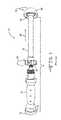
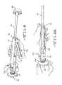
- FIG. 3illustrates a perspective view of the spindle-type orthopedic impactor of the present invention.
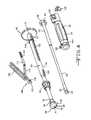
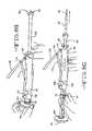
- FIG. 4is a perspective view of an embodiment of the components comprising the orthopedic impactor of the present invention.
- FIG. 5illustrates a perspective view of an embodiment of an orthopedic prosthetic cup being attached to the impactor shown in FIG. 3 .
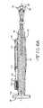
- FIGS. 6-6Billustrate cross-sectional views of the locking mechanism subassembly connecting a prosthetic cup to the impactor shown in FIG. 3 .
- FIGS. 7 and 7Aillustrate perspective views of alternate embodiments of prosthetic cup to impactor engagement mechanisms.
- FIGS. 8-8Dare perspective views illustrating an embodiment of a disassembly process of the present invention.
- FIGS. 3-5 , 6 - 6 B and 8 - 8 Dillustrate a spindle-type orthopedic impactor 50 of the present invention.
- the orthopedic impactor 50comprises a distal end portion 52 spaced from a proximal end portion 54 with a length portion residing therebetween.
- An orthopedic prosthetic cup 56is designed to be positioned at the distal end of the impactor 50 and a strike plate 58 resides at the proximal end of the impactor 50 .
- the impactor 50 of the present inventioncomprises an elongated body portion 60 , a connection rod 62 positioned within the body 60 , and a handle portion 64 residing circumferentially around the body 60 .
- the body portion 60extends lengthwise along longitudinal axis A-A.
- the body portion 60is of a “one-piece” construction in that the strike plate 58 , located at the proximal end of the impactor 50 , and a prosthetic cup engagement portion 66 , located at the distal end of the impactor 50 are fluidly connected in one-piece.
- the elongated body portion 60is constructed with a curved outer sidewall 68 . More preferably, the elongated body portion 60 is constructed with an annular sidewall 68 with an outer diameter ranging from about 1 cm to about 5 cm. Although it is preferred that the elongated body is constructed with an outer circular cross-section, the body 60 may be constructed of a multitude of cross-sectional shapes that include but are not limited to a rectangle, a square, a triangle, a hexagon, or an oval.
- the elongated body portion 60has a length that ranges from about 5 cm to about 50 cm and more preferably from about 10 cm to about 25 cm.
- the body portion 60may be constructed of either a polymer or metallic material.
- the body portion 60may be constructed from polymers comprising polyether ether ketone (PEEK), acryloyl b-alanine (ABA), acryloyl b-alanine tri-block copolymers and the like.
- the body portionmay be constructed from metals comprising aluminum, stainless steel, cobalt nickel alloys, highly alloyed ferritic stainless steel containing molybdenum and chromium, and nickel chromium- and molybdenum-containing alloys and the like.
- the elongated body portion 60has an internal cavity 70 that extends from a region of a body proximal end portion 72 through a distal end 74 of the body 60 along axis A-A.
- the body cavity 70has a cylindrical shape with a generally circular cross-section providing a cavity diameter ranging from about 0.5 cm to about 4 cm.
- the cavity 70may be constructed of a multitude of cross-sectional shapes that include but are not limited to, a rectangle, a square, a triangle, a hexagon, an oval, or the like.
- connection rod 62has a rod proximal end portion 76 spaced apart from a rod distal end portion 78 with a rod length portion 80 residing therebetween.
- the connection rod 62preferably positioned within the cavity 70 of the body 60 such that its proximal end portion resides within the proximal end portion of the body cavity 70 .
- the distal end portion of the rod 62protrudes from the distal end of the cavity 70 .
- the rod 62is constructed such that it is in a slidable relationship within the cavity 70 .
- connection rod 62has a length ranging from about 5 cm to about 50 cm and more preferably from about 10 cm to about 20 cm.
- the connection rod 62has a circular cross-section.
- the rod 62has a cross-sectional diameter ranging from about 0.5 cm to about 4 cm.
- the rod 62may be constructed of a multitude of cross-sectional shapes that include but are not limited to, a rectangle, a square, a triangle, a hexagon, or an oval.
- connection rod 62may be constructed from metals comprising aluminum, stainless steel, cobalt nickel alloys, highly alloyed ferritic stainless steel containing molybdenum and chromium, and nickel-, chromium- and molybdenum-containing alloys and the like.
- the distal end 78 of the rod 62has a threaded end 80 that is design to engage with a threaded receiving end of the prosthetic cup 56 .
- a throughbore opening 82is positioned at the opposite, proximal end 76 of the rod 62 .
- the throughbore opening 82extends through the diameter of the rod, perpendicular to longitudinal axis A-A.
- the connection rod throughbore 82allows for the placement of a connection rod pin 84 .
- the pinis placed through the opening such that its opposing ends are in a perpendicular relationship to the longitudinal length of the rod 62 .
- this pin 84 and throughbore 82 feature of the rod 62enable controlled movement of the rod 62 and cup 56 .
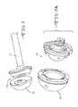
- the prosthetic cup engagement portion 66resides at the distal end 74 of the elongated body 60 .
- the prosthetic cup engagement portion 66comprises a frustro-conical portion 86 that fluidly transitions into an end cap portion 88 .
- the frustro-conical portion 86 residing at the distal end of the body 60has a wider diameter than the diameter of the body length portion.
- the end cap 88has a curved outer surface 90 .
- These features of the cup engagement portion 88are designed to contact the contoured inner surface of the prosthetic cup 56 .
- the wider outer surface of the end cap 88provides an increased surface area. The greater surface area provided by the outer surface of the end cap portion 88 distributes the impaction force over a wider contact interface, therefore minimizing stress risers at the impactor 50 to prosthetic cup 56 connection point.
- the strike plate 58resides at the opposite, proximal end of the elongated body 60 .
- the strike plate 58is designed with a strike plate diameter that is wider than the outer diameter of the body 60 .
- the diameter of the strike plate 58ranges from about 2 cm to about 10 cm.
- the strike plate 58is fluidly attached to the proximal end of the elongated body 60 .
- the handle portion 64is positioned circumferentially around the outer diameter of the proximal end of the body 60 . More specifically, the handle portion 64 is positioned circumferentially around the exterior of the annular sidewall 68 of the body 60 .
- the handle portion 64is designed such that it is in a slidable relationship with the sidewall 68 along axis A-A.
- the handle portion 64has a generally tubular form.
- the handle portion 64preferably has an inner handle diameter ranging from about 1 cm to about 3 cm.
- a ribbed gripping surfacepreferably comprises an outer handle surface 92 .
- a proximal ring 94 and a distal ring 96are positioned adjacent respective proximal and distal ends of the handle portion 64 . More specifically, the rings 94 , 96 are positioned circumferentially around the exterior surface of the annular sidewall 68 of the body 62 . In a preferred embodiment, the distal ring 96 and proximal ring 94 each have an outer diameter ranging from about 1 cm to about 5 cm and an inner diameter ranging from about 0.5 cm to about 4 cm.
- Opposed distal ring positioning pinsextend from an inner surface of the distal ring 96 . These positioning pins are designed such that they fit within geometrically opposed grooves 100 residing within a portion of the exterior surface of the annular sidewall 68 of the body 60 .
- the grooves 100are configured similar to that of a “dog leg” such that when the pins are received within the corresponding grooves 100 after the distal ring 96 has been rotated and locked into position with respect to the body 60 .
- the grooveis shaped similarly to that of the letter “J”.
- the proximal ring 94is positioned opposite the distal ring 96 and adjacent to the proximal end of the handle portion 64 .
- the proximal ring 94is preferably in a slidable relationship with the exterior surface of the sidewall 68 of the body 60 along longitudinal axis A-A.
- connection rod pin 84extending through opposite sides of the connection rod 62 , are positioned through respective slot openings 102 extending through opposing sides of the annular sidewall of the body 60 .
- two opposing slot openings 102extend through the annular sidewall of the proximal ring portion of the body 60 .
- Each of the slot openings 102has a distal and proximal slot portion and a slot length therebetween.
- the slots 102are constructed such that they are contained within the boundaries of the annular sidewall of the body 60 .
- the proximal end portion of the slotis designed not to protrude through the proximal end 72 of the body 60 .
- a portion of annular sidewall 68separates the proximal end of the slot 102 and the proximal end of the elongated body 60 .
- the length of the portion of annular sidewall 68 positioned between the proximal end of the slot 102 and the proximal end of the elongated body 60ranges from about 0.5 cm to about 5 cm or from about 0.1% to about 5% of the length of the elongated body 60 .
- This portion of sidewall 68 that separates the respective proximal ends of the slot 102 and body 60prevents the proximal end of the connection rod 62 from contacting the body 60 , therefore minimizing the transfer of the impaction force to the connection rod 62 and prosthetic cup 56 during the implantation procedure.
- the ends of the rod pin 84extend through the sidewall slots 102 , the ends are positioned through opposing throughbores of the proximal ring 94 . More specifically, the ends of the pins 84 are positioned through opposing throughbores that extend through the annular sidewall of the proximal ring 94 .
- longitudinal movement of the connection rod 62is controlled through movement of the proximal ring 94 .
- the proximal ring 94is slid along axis A-A of the elongated body, the rod 62 is correspondingly moved within the cavity 70 of the impactor body.
- the prosthetic cup 56is connected to the distal end of the impactor 50 , the cup 56 is also correspondingly moved.
- a spring 104resides between the strike plate 58 and the proximal ring 94 . More specifically, the spring 104 resides circumferentially around the exterior surface of the annular sidewall 68 of the body 60 between the strike plate 58 and the proximal end of the proximal ring 94 .
- the spring 104provides a bias force that enhances separation between the strike plate 58 and the proximal ring 94 . More specifically, the spring 104 provides the bias force that separates the proximal ring 94 and proximal end of the connection rod 62 from the inner surface of the strike plate 58 .
- the impactor 50 of the present inventionis designed such that the majority of the impaction force is transferred through the annular sidewall 68 of the elongated body 60 and not the connection rod 62 . As a result, the concentration of impaction forces at the distal end of the rod 62 , which might damage the connected prosthetic cup 56 , is reduced.
- a lever arm subassembly 106is pivotally connected to the exterior surface of the handle portion 64 .
- the lever arm subassembly 106comprises a lever arm 108 , an intermediate arm 110 and an end arm portion 112 .
- the intermediate arm 110is pivotally connected to the lever arm 108 and the end arm 112 is pivotally connected to the intermediate arm 110 .
- a pivot pin 114is placed through each of the connections, connecting the lever arm 108 to the intermediate arm 110 and the intermediate arm 110 to the end arm 112 .
- a lever arm pivot pin 116extends perpendicularly through a lever arm throughbore 118 and connects with a corresponding lever arm support portion 120 positioned at the distal end portion of the outer surface of the handle 64 .
- the lever arm 108preferably comprises a wedge portion 122 residing at its distal end. More specifically, the lever arm throughbore 118 extends perpendicularly through the wedge portion 122 of the lever arm 108 .
- the wedge portion 122 of the lever arm 108is further positioned such that the angled end of the wedge 122 is positionable between the distal ring 96 and the distal end of the handle portion 64 .
- the lever arm subassembly 106is designed such that when the lever arm 108 is moved in a pivotable manner in a downward direction towards the exterior surface of the handle portion 64 , the wedge portion 122 drives the distal end of the handle portion 64 away from the distal ring 96 . More specifically, the distal end of the slanted wedge portion 122 is positioned between the distal ring 96 and the distal end of the handle portion 64 , adjacent the lever arm support portion 120 . As the lever arm 108 moves in the downward direction, the distal end of the wedge portion 122 is driven further between the distal ring 96 and the handle portion 64 .
- the slanted surface and the body of the wedge portion 122move the handle portion 64 in a proximal direction, along longitudinal axis A-A, against the spring 114 towards the strike plate 58 .
- This motionmoves the proximal ring 94 in a proximal direction towards the strike plate 58 , which in turn, moves the distal end 78 of the rod 62 within the cavity 70 of the body 60 .
- a prosthetic cup 56is attached to the distal end 78 of the connection rod 62 , proximal movement of the rod 62 pulls the cup 56 closer to the distal end of the elongated body 60 as shown in FIGS. 6 , 6 A and 6 B. More specifically, the curved outer surface of the prosthetic cup engagement portion 66 contacts the inside surface of the prosthetic cup 56 and provides a secure fitting therebetween. In addition, the outer surface of the end cap 88 provides a larger surface area that distributes the impaction force.
- the prosthetic cup 56is secured to the distal end of the impactor 50 through clockwise rotation of the strike plate 58 . Accordingly, the impactor 50 is detached from the prosthetic cup through counter-clockwise rotation of the strike plate 58 shown in FIG. 8A .
- a ratchet post 124provided at the proximal end of the end arm 112 .
- the ratchet post 124is designed with teeth that protrude from a portion of the outer surface of the post 124 .
- the ratchet post 124is received within a ratchet catch locking mechanism 126 located at the proximal end portion of the handle 64 . Once the ratchet post is received within the mechanism, the corresponding ratchet teeth become entrapped therewithin, thus preventing sliding movement of the handle portion 64 .
- the sliding movement of the proximal ring 94is also prevented since it is positioned between the handle portion 64 and the biasing force of the spring 114 at the strike plate end.
- the locking mechanism 126is constructed such that when the lever arm 108 is depressed, the ratchet post 124 moves in a proximal direction within the locking mechanism thereby becoming entrapped therewithin.
- the ratchet locking mechanism 126comprises a release lever 128 .
- the ratchet post 124 and corresponding ratchet locking mechanism 126enable the lever arm 108 to be locked in multiple locations within the operating movement of the arm 108 .
- cup attachment meanscould also be used.
- a cup-and-socket 130 type mechanismmay be used.
- the cup attachment mechanismmay be adapted for a double mobility prosthetic cup utilizing an expandable dome mechanism as disclosed in U.S. patent application Ser. No. 12/694,524, which is assigned to the assignee of the present invention and incorporated herein by reference may be used.
- a grasping plate cup attachment mechanism 132 illustrated in FIG. 7Adisclosed in U.S. patent application Ser. No. 13/219,767, which is assigned to the assignee of the present invention and incorporated herein by reference may also be used as well.
- the impactor and prosthetic cup assemblyis inserted within the target area of the acetabulum. Once correctly positioned, a series of impaction forces are delivered to the proximal end of the strike plate 58 securing the cup 56 therewithin. After the cup 56 is secured within the acetabulum, the cup is removed from the end of the impactor 50 . As shown in FIGS. 8 and 8A , the release lever 128 of the ratchet post locking mechanism 126 is depressed. This action disengages the ratchet post 124 from the locking mechanism 126 thereby enabling the lever arm 108 to move freely away from the external surface of the handle portion 64 .
- the lever arm 108is pivoted away from the exterior surface of the handle portion 64 . This lever arm 108 movement distally extends the connector rod 62 .
- the strike plate 58is then rotated in a counter clockwise direction to disengage the prosthetic cup 56 from the connection rod 62 and the body of the impactor is removed from the patient.
- the impactor 50 of the present inventionmay be further disassembled for cleaning and disinfection.
- the distal ring 96is first disengaged from the “J” groove 100 .
- the distal ring 96 and handle portion 64are able to be moved freely along axis A-A.
- the respective strike plate 58 and frusto-conical prosthetic cup engagement end 66 of the one-piece body 60 construction of the elongated body 60prevent complete disassembly of the components comprising the impactor 50 , i.e.
Landscapes
- Health & Medical Sciences (AREA)
- Transplantation (AREA)
- Orthopedic Medicine & Surgery (AREA)
- Heart & Thoracic Surgery (AREA)
- Cardiology (AREA)
- Oral & Maxillofacial Surgery (AREA)
- Engineering & Computer Science (AREA)
- Biomedical Technology (AREA)
- Physical Education & Sports Medicine (AREA)
- Vascular Medicine (AREA)
- Life Sciences & Earth Sciences (AREA)
- Animal Behavior & Ethology (AREA)
- General Health & Medical Sciences (AREA)
- Public Health (AREA)
- Veterinary Medicine (AREA)
- Prostheses (AREA)
Abstract
Description
Claims (26)
Priority Applications (1)
| Application Number | Priority Date | Filing Date | Title |
|---|---|---|---|
| US13/351,302US8585709B2 (en) | 2011-01-17 | 2012-01-17 | Straight cup impactor with lever arm |
Applications Claiming Priority (2)
| Application Number | Priority Date | Filing Date | Title |
|---|---|---|---|
| US201161433383P | 2011-01-17 | 2011-01-17 | |
| US13/351,302US8585709B2 (en) | 2011-01-17 | 2012-01-17 | Straight cup impactor with lever arm |
Publications (2)
| Publication Number | Publication Date |
|---|---|
| US20120184965A1 US20120184965A1 (en) | 2012-07-19 |
| US8585709B2true US8585709B2 (en) | 2013-11-19 |
Family
ID=45495818
Family Applications (1)
| Application Number | Title | Priority Date | Filing Date |
|---|---|---|---|
| US13/351,302Active2032-08-03US8585709B2 (en) | 2011-01-17 | 2012-01-17 | Straight cup impactor with lever arm |
Country Status (2)
| Country | Link |
|---|---|
| US (1) | US8585709B2 (en) |
| EP (1) | EP2476397B1 (en) |
Cited By (3)
| Publication number | Priority date | Publication date | Assignee | Title |
|---|---|---|---|---|
| US20160135963A1 (en)* | 2014-11-19 | 2016-05-19 | Symmetry Medical, Inc. | Method of attachment of implantable cup to a cup impactor |
| US10226294B2 (en) | 2015-07-02 | 2019-03-12 | Viant As&O Holdings, Llc | Hybrid straight cup impactor |
| US20230172730A1 (en)* | 2020-04-20 | 2023-06-08 | Howmedica Osteonics Corp. | Inserter for glenosphere |
Families Citing this family (12)
| Publication number | Priority date | Publication date | Assignee | Title |
|---|---|---|---|---|
| US8900245B2 (en)* | 2012-06-07 | 2014-12-02 | Howmedica Osteonics Corp. | Glenosphere inserter and impactor |
| CN102908214B (en)* | 2012-09-21 | 2015-01-28 | 联合骨科器材股份有限公司 | Acetabular cup implanter |
| CN112773580B (en) | 2015-07-27 | 2024-06-18 | 黑普创新技术有限责任公司 | Ball and cup impactor for implanting hip joint prosthesis |
| US10470896B2 (en)* | 2015-07-27 | 2019-11-12 | Ren-Hong Huang | Surgical inserter |
| CN108272478B (en)* | 2017-01-05 | 2020-11-03 | 黄仁宏 | Implanter for medical devices |
| EP3714448B1 (en)* | 2017-11-21 | 2023-12-20 | Cedarome Canada Inc. | Impactor mechanism for virtual reality surgery simulation system and telesurgery |
| CN109498224B (en)* | 2018-12-21 | 2023-12-12 | 天衍医疗器材有限公司 | Compression bone cement type hip joint prosthesis beating and pulling device |
| CN111449811B (en)* | 2019-01-18 | 2025-05-30 | 北京纳通医学科技研究院有限公司 | Acetabular cup insertion device and joint replacement device |
| US11090163B1 (en)* | 2021-01-09 | 2021-08-17 | Zafer Termanini | Interlocking reverse hip prosthesis with removable tapered central post |
| CN113796964B (en)* | 2021-09-27 | 2023-06-20 | 天衍医疗器材有限公司 | Terminal device of orthopedic surgery robot |
| CN218528989U (en)* | 2022-08-10 | 2023-02-28 | 杭州锐健马斯汀医疗器材有限公司 | Striking device |
| KR102596552B1 (en)* | 2023-03-24 | 2023-11-02 | 큐렉소 주식회사 | Medical surgical device having tool movement distance display function |
Citations (111)
| Publication number | Priority date | Publication date | Assignee | Title |
|---|---|---|---|---|
| US1942422A (en) | 1931-06-17 | 1934-01-09 | Daisy B Hanna | Douche device |
| US4305394A (en) | 1980-12-22 | 1981-12-15 | Bertuch Jr Charles J | Acetabular cup positioning instrument |
| USD272648S (en) | 1981-08-03 | 1984-02-14 | Zimmer, Inc. | Reamer/rasp tool with disposable, debris retaining cutting surface |
| USD273806S (en) | 1981-08-03 | 1984-05-08 | Zimmer, Inc. | Reamer/rasp tool, with disposable, debris retaining cutting surface |
| US4475549A (en) | 1982-01-18 | 1984-10-09 | Indong Oh | Acetabular cup positioner and method |
| US4520511A (en) | 1981-10-26 | 1985-06-04 | Paribelli Gianezio | Hip prosthesis with expanding femoral component |
| US4528980A (en) | 1983-10-19 | 1985-07-16 | Howmedica, Inc. | Acetabulum sizer and drill guide |
| US4587964A (en) | 1985-02-05 | 1986-05-13 | Zimmer, Inc. | Rasp tool |
| US4632111A (en) | 1985-03-21 | 1986-12-30 | Minnesota Mining And Manufacturing Company | Acetabular cup positioning apparatus |
| US4716894A (en) | 1986-08-27 | 1988-01-05 | Zimmer, Inc. | Acetabular cup inserting instrument |
| US4765328A (en) | 1987-08-10 | 1988-08-23 | Osteonics Corp. | Surgical instrument handle coupling |
| US4904267A (en) | 1983-08-12 | 1990-02-27 | Ab Idea | Method and device for fixing a joint prosthesis |
| US4919679A (en) | 1989-01-31 | 1990-04-24 | Osteonics Corp. | Femoral stem surgical instrument system |
| US4921493A (en) | 1986-08-11 | 1990-05-01 | Zimmer, Inc. | Rasp tool |
| US5019105A (en) | 1989-08-03 | 1991-05-28 | Biomet, Inc. | Acetabular cup prosthesis assembly |
| US5037424A (en) | 1989-12-21 | 1991-08-06 | Aboczsky Robert I | Instrument for orienting, inserting and impacting an acetabular cup prosthesis |
| US5061270A (en) | 1991-03-18 | 1991-10-29 | Aboczky Robert I | System for orienting, inserting and impacting an acetabular cup prosthesis |
| EP0453694A1 (en) | 1989-04-05 | 1991-10-30 | HIGH TECH INDUSTRIES - H.T.I., Société Anonyme dite: | Cementless acetabular cup for total hip prosthesis |
| US5062854A (en) | 1988-10-07 | 1991-11-05 | Pfizer Hospital Products Group | Prosthetic device and method of implantation |
| US5089003A (en) | 1989-12-22 | 1992-02-18 | Zimmer, Inc. | Rasp tool including detachable handle member |
| US5116339A (en) | 1990-07-11 | 1992-05-26 | Glock Steven R | Acetabular cup installation tool and method of installing an acetabular cup |
| US5124106A (en) | 1991-03-25 | 1992-06-23 | Zimmer, Inc. | Method of making a femoral rasp |
| US5133766A (en) | 1991-03-04 | 1992-07-28 | Halpern Alan A | Femoral head remodeling and femoral insert and drilling aid therefor |
| US5169399A (en) | 1991-10-17 | 1992-12-08 | Boehringer Mannheim Corporation | Acetabular cup impactor |
| US5190549A (en) | 1990-08-02 | 1993-03-02 | Exactech, Inc. | Locking surgical tool handle system |
| US5234432A (en) | 1992-03-13 | 1993-08-10 | Brown Byron L | Method and apparatus for definitive cutting of a femur |
| US5261915A (en) | 1992-04-16 | 1993-11-16 | Scott M. Durlacher | Femur bone rasp with adjustable handle |
| US5324293A (en) | 1992-11-13 | 1994-06-28 | U.S. Medical Products, Inc. | Surgical broach and broach holder |
| US5342362A (en) | 1991-08-29 | 1994-08-30 | Zimmer Inc. | System and instrumentation for torsionally testing femoral rasp and hip stem implant including motion indicator |
| US5364403A (en) | 1993-09-20 | 1994-11-15 | Zimmer, Inc. | Acetabular cup positioner |
| EP0470912B1 (en) | 1990-06-29 | 1995-05-17 | Medinov Sa | Prosthetic assembly comprising a hip cup and an impact apparatus |
| US5417696A (en) | 1991-02-13 | 1995-05-23 | Howmedica Inc. | Acetabular cup positioning insert with release mechanism |
| US5443471A (en) | 1993-02-16 | 1995-08-22 | Howmedica, Inc. | Quick release handle assembly |
| US5454815A (en) | 1992-04-01 | 1995-10-03 | Imt Integral Medizintechnik Trading Ag | Bone rasp made of plastics |
| US5485887A (en) | 1993-03-30 | 1996-01-23 | Imt Integral Medizintechnik Ag | Pneumatic impact tool and piston for a pneumatic impact tool |
| US5540697A (en) | 1993-02-12 | 1996-07-30 | U.S. Medical Products, Inc. | Prosthetic socket installation apparatus and method |
| US5584837A (en) | 1993-08-13 | 1996-12-17 | Petersen; Thomas D. | Acetabular cup inserter for orthopedic |
| EP0535973B1 (en) | 1991-10-04 | 1997-03-12 | JOHNSON & JOHNSON ORTHOPAEDICS, INC. | An acetabular cup inserter |
| US5658294A (en) | 1993-12-02 | 1997-08-19 | Sulzer Orthopedics Inc. | Instrument for holding an acetabular cup |
| US5665091A (en) | 1996-02-09 | 1997-09-09 | Howmedica Inc. | Surgical broach |
| US5683399A (en) | 1995-12-01 | 1997-11-04 | Stelkast Incorporated | Acetabular cup insertion tool |
| US5707374A (en) | 1995-06-09 | 1998-01-13 | Merck Patent Gesellschaft Mit Beschrankter Haftung | Apparatus for preparing the medullary cavity |
| US5720750A (en) | 1993-04-07 | 1998-02-24 | Sulzer Medizinaltechnik Ag | Device for the preparation of a tubular bone for the insertion of an implant shaft |
| US5863295A (en) | 1994-06-01 | 1999-01-26 | Implex Corporation | Prosthetic device and method of implantation |
| US5913860A (en) | 1998-02-27 | 1999-06-22 | Synthes (Usa) | Surgical nail inserter |
| US5976148A (en) | 1996-11-12 | 1999-11-02 | Ppc | Set of ancillary equipment for the implantation of acetabular cups of hip prosthesis, and prosthetic acetabular cup assembly ready to be implanted |
| US5993455A (en) | 1996-11-13 | 1999-11-30 | Noble; Philip C. | Surgical broach and methods for preparing the medullary cavity of a femur in hip arthroplasty |
| US6063124A (en) | 1999-03-01 | 2000-05-16 | Amstutz; Harlan C. | Acetabular cup prosthesis insertion and removal assembly and technique |
| US6120508A (en) | 1998-06-19 | 2000-09-19 | Imt Integral Medizintechnik Ag | Rasp determined for one-time use, particularly bone rasp as well as process for its production |
| US6197065B1 (en) | 1993-11-01 | 2001-03-06 | Biomet, Inc. | Method and apparatus for segmental bone replacement |
| US20010051830A1 (en) | 1997-03-14 | 2001-12-13 | Kurt F. James | Prosthetic implant and surgical tool |
| US20020004660A1 (en) | 2000-02-24 | 2002-01-10 | Stryker Instruments | Bioabsorbable plates. fasteners, tools and method of using same |
| US6432141B1 (en) | 1999-03-31 | 2002-08-13 | Gregory W. Stocks | Joint prosthesis assembly and method for installing same |
| US20020116007A1 (en) | 2001-02-16 | 2002-08-22 | Lewis Randall J. | Method and apparatus for removing an acetabular cup |
| US20020193797A1 (en) | 2001-06-14 | 2002-12-19 | Johnson Wesley D. | Apparatus and method for minimally invasive total joint replacement |
| US20030009234A1 (en) | 2001-07-05 | 2003-01-09 | Treacy Patrick J. | Pelvic prosthesis plus methods and tools for implantation |
| US20030050645A1 (en) | 2002-10-30 | 2003-03-13 | Parker Brad A. | Acetabular cup impactor |
| US20030083668A1 (en) | 2001-10-30 | 2003-05-01 | Christopher Rogers | Slaphammer tool |
| US20030088316A1 (en) | 2001-11-05 | 2003-05-08 | Ramin Ganjianpour | Modular femoral prosthesis |
| US6626913B1 (en) | 1999-03-03 | 2003-09-30 | Smith & Nephew, Inc. | Methods, systems, and instruments for inserting prosthetic implants |
| US20030187512A1 (en) | 2002-04-01 | 2003-10-02 | Phil Frederick | Liner assembly for prosthetic components |
| US20030220698A1 (en) | 2000-04-26 | 2003-11-27 | Dana Mears | Method and apparatus for performing a minimally invasive total hip arthroplasty |
| US20030229356A1 (en) | 2002-06-10 | 2003-12-11 | Donald Dye | Curved acetabular shell impaction instrument and method of use |
| US6663636B1 (en) | 2002-03-12 | 2003-12-16 | United Orthopedic Corporation | Femur rasp fastener |
| WO2004010882A1 (en)* | 2002-07-25 | 2004-02-05 | Enztec Limited | Surgical impactor with workpiece engageable head |
| DE10250390A1 (en) | 2002-10-29 | 2004-05-13 | Plus Endoprothetik Ag | Hip joint cup handling involves spreader cone of axi-slots dividing wall sectors expanded radially onto cup inner wall by central expander for handling all cup types. |
| EP1190687B1 (en) | 2000-09-21 | 2004-07-28 | Sulzer Orthopedie S.A. | Impactor for use in orthopaedics |
| EP1447058A1 (en) | 1998-09-30 | 2004-08-18 | Bard Peripheral Vascular, Inc. | Delivery mechanism for implantable stent |
| US20040215200A1 (en) | 2003-01-17 | 2004-10-28 | Alain Tornier | Ancillary tool and method for positioning a prosthetic acetabulum of a hip prosthesis |
| US6811569B1 (en) | 1999-11-19 | 2004-11-02 | Proconcept Sa | Expansible acetabular prosthesis with double mobility |
| US20050038443A1 (en) | 2002-12-12 | 2005-02-17 | Hedley Anthony K. | Surgical tools for joint replacement |
| US20050075736A1 (en) | 2003-10-03 | 2005-04-07 | Howmedica Osteonics Corp. | Expandable augment trial |
| WO2005044153A1 (en) | 2003-11-10 | 2005-05-19 | Precimed, S.A. | Inserter for minimally invasive joint surgery |
| US20050137603A1 (en) | 2003-11-12 | 2005-06-23 | Kevin Belew | Acetabular cup positioning instrument |
| US20050171548A1 (en) | 2003-11-18 | 2005-08-04 | Kelman David C. | Surgical technique and instrumentation for minimal incision hip arthroplasty surgery |
| US20050187562A1 (en) | 2004-02-03 | 2005-08-25 | Grimm James E. | Orthopaedic component inserter for use with a surgical navigation system |
| US20050222572A1 (en) | 2002-02-08 | 2005-10-06 | Gursharan Chana | Surgical devices and methods of use |
| US20050228395A1 (en) | 2004-03-05 | 2005-10-13 | Benoist Girard Sas | Prosthetic acetabular cup inserter |
| US20050234462A1 (en) | 2004-01-05 | 2005-10-20 | Hershberger Troy W | Method and instrumentation for performing minimally invasive hip arthroplasty |
| US20060052780A1 (en) | 2001-02-15 | 2006-03-09 | Spinecore, Inc. | Wedge plate inserter/impactor and related methods for use in implanting an artificial intervertebral disc |
| WO2006061708A2 (en) | 2004-12-09 | 2006-06-15 | Precimed S.A. | Surgical tool holder for facilitated sterilization |
| US20060149285A1 (en) | 2004-12-09 | 2006-07-06 | Precimed S.A. | Inserter for minimally invasive joint surgery |
| US7192449B1 (en) | 1999-01-29 | 2007-03-20 | Orthopaedic Research Institute, Inc. | Constrained acetabular insert for total hip arthroplasty |
| US20070156155A1 (en) | 2006-01-03 | 2007-07-05 | Parker Brad A | Surgical cup impactor |
| US20070167952A1 (en) | 2005-08-24 | 2007-07-19 | Jonas Burgi | Surgical tool holder for facilitated sterilization |
| WO2007098549A1 (en) | 2006-03-03 | 2007-09-07 | Portland Orthopaedics Limited | Multi function hammer |
| US20070225725A1 (en) | 2006-03-21 | 2007-09-27 | Zimmer Technology, Inc. | Modular acetabular component inserter |
| US20070270783A1 (en) | 2004-06-22 | 2007-11-22 | Lukas Zumsteg | Device for Placing or Removing Joints or Joints Sockets |
| US20070288096A1 (en) | 2006-06-02 | 2007-12-13 | Gabriel Surma | System and method for inserting an implant |
| US20070293869A1 (en) | 2005-12-20 | 2007-12-20 | Howmedica Osteonics Corp. | Curved acetabular positioner, impactor and reamer handle |
| US20080004628A1 (en) | 2006-06-30 | 2008-01-03 | Patrick White | Surgical tool holder and disposable broach assembly |
| US20080021481A1 (en) | 2006-05-01 | 2008-01-24 | Precimed S.A. | Inserter for minimally invasive joint surgery having interchangeable thread |
| US20080033444A1 (en) | 2006-03-06 | 2008-02-07 | Howmedica Osteonics Corp. | Compound offset handle |
| US7335207B1 (en) | 2003-11-26 | 2008-02-26 | Biomet Manufacturing Corp. | Minimally invasive cup impactor |
| US20080077249A1 (en) | 2004-10-13 | 2008-03-27 | Thomas Gradel | Instruments for Setting Acetabular Cup |
| US20080146969A1 (en) | 2006-12-15 | 2008-06-19 | Kurtz William B | Total joint replacement component positioning as predetermined distance from center of rotation of the joint using pinless navigation |
| US20080154261A1 (en) | 2006-12-21 | 2008-06-26 | Jonas Burgi | Prosthesis Component Holder Attachable to an Inserter Handle |
| US20080243127A1 (en) | 2001-05-25 | 2008-10-02 | Conformis, Inc. | Surgical Tools for Arthroplasty |
| US20080255565A1 (en) | 2006-11-20 | 2008-10-16 | Fletcher Henry H | Broach handle for minimally invasive hip replacement surgery |
| US20080262503A1 (en) | 2005-12-15 | 2008-10-23 | Erich Johann Muller | Surgical Tool and Method |
| WO2008128282A1 (en) | 2007-04-20 | 2008-10-30 | Portland Orthopaedics Limited | Acetabular prosthesis assembly with offset insert |
| US20080275450A1 (en) | 2005-09-29 | 2008-11-06 | Symmetry Medical, Inc. | Minimally invasive surgical driver |
| US20090112214A1 (en) | 2007-10-30 | 2009-04-30 | Hipco, Inc. | Device and Method for Hip Distention and Access |
| US20090182334A1 (en) | 2008-01-10 | 2009-07-16 | Peter Brehm | Method and Apparatus for Impacting Bone Material |
| US7585301B2 (en) | 2002-06-12 | 2009-09-08 | Howmedica Osteonics Corp. | Modular hip inserter/positioner |
| US20090240256A1 (en) | 2008-03-19 | 2009-09-24 | Biomet Manufacturing Corp. | Method And Apparatus For Implanting an Augment |
| US7604667B2 (en) | 2004-09-15 | 2009-10-20 | Wright Medical Technology, Inc. | Unitary acetabular cup prosthesis with extension for deficient acetabulum |
| WO2009136284A1 (en) | 2008-05-07 | 2009-11-12 | Benoist Girard Sas | Prosthetic acetabular cup inserter and impactor |
| US20090281545A1 (en) | 2008-03-05 | 2009-11-12 | Allston J. Stubbs | Method and Apparatus for Arthroscopic Assisted Arthroplasty of the Hip Joint |
| US7621921B2 (en) | 2006-01-25 | 2009-11-24 | Symmetry Medical, Inc | Split thread orthopaedic implant impactor |
| EP1308140B1 (en) | 2000-10-03 | 2012-01-18 | DePuy Products, Inc. | Acetabular cup and reamer assembly |
- 2012
- 2012-01-17EPEP12151448.3Apatent/EP2476397B1/enactiveActive
- 2012-01-17USUS13/351,302patent/US8585709B2/enactiveActive
Patent Citations (121)
| Publication number | Priority date | Publication date | Assignee | Title |
|---|---|---|---|---|
| US1942422A (en) | 1931-06-17 | 1934-01-09 | Daisy B Hanna | Douche device |
| US4305394A (en) | 1980-12-22 | 1981-12-15 | Bertuch Jr Charles J | Acetabular cup positioning instrument |
| USD272648S (en) | 1981-08-03 | 1984-02-14 | Zimmer, Inc. | Reamer/rasp tool with disposable, debris retaining cutting surface |
| USD273806S (en) | 1981-08-03 | 1984-05-08 | Zimmer, Inc. | Reamer/rasp tool, with disposable, debris retaining cutting surface |
| US4520511A (en) | 1981-10-26 | 1985-06-04 | Paribelli Gianezio | Hip prosthesis with expanding femoral component |
| US4475549A (en) | 1982-01-18 | 1984-10-09 | Indong Oh | Acetabular cup positioner and method |
| US4904267A (en) | 1983-08-12 | 1990-02-27 | Ab Idea | Method and device for fixing a joint prosthesis |
| US4528980A (en) | 1983-10-19 | 1985-07-16 | Howmedica, Inc. | Acetabulum sizer and drill guide |
| US4587964A (en) | 1985-02-05 | 1986-05-13 | Zimmer, Inc. | Rasp tool |
| US4632111A (en) | 1985-03-21 | 1986-12-30 | Minnesota Mining And Manufacturing Company | Acetabular cup positioning apparatus |
| US4921493A (en) | 1986-08-11 | 1990-05-01 | Zimmer, Inc. | Rasp tool |
| US4716894A (en) | 1986-08-27 | 1988-01-05 | Zimmer, Inc. | Acetabular cup inserting instrument |
| US4765328A (en) | 1987-08-10 | 1988-08-23 | Osteonics Corp. | Surgical instrument handle coupling |
| US5062854A (en) | 1988-10-07 | 1991-11-05 | Pfizer Hospital Products Group | Prosthetic device and method of implantation |
| US4919679A (en) | 1989-01-31 | 1990-04-24 | Osteonics Corp. | Femoral stem surgical instrument system |
| EP0453694A1 (en) | 1989-04-05 | 1991-10-30 | HIGH TECH INDUSTRIES - H.T.I., Société Anonyme dite: | Cementless acetabular cup for total hip prosthesis |
| US5019105A (en) | 1989-08-03 | 1991-05-28 | Biomet, Inc. | Acetabular cup prosthesis assembly |
| US5037424A (en) | 1989-12-21 | 1991-08-06 | Aboczsky Robert I | Instrument for orienting, inserting and impacting an acetabular cup prosthesis |
| US5089003A (en) | 1989-12-22 | 1992-02-18 | Zimmer, Inc. | Rasp tool including detachable handle member |
| EP0470912B1 (en) | 1990-06-29 | 1995-05-17 | Medinov Sa | Prosthetic assembly comprising a hip cup and an impact apparatus |
| US5116339A (en) | 1990-07-11 | 1992-05-26 | Glock Steven R | Acetabular cup installation tool and method of installing an acetabular cup |
| US5190549A (en) | 1990-08-02 | 1993-03-02 | Exactech, Inc. | Locking surgical tool handle system |
| US5417696A (en) | 1991-02-13 | 1995-05-23 | Howmedica Inc. | Acetabular cup positioning insert with release mechanism |
| US5133766A (en) | 1991-03-04 | 1992-07-28 | Halpern Alan A | Femoral head remodeling and femoral insert and drilling aid therefor |
| US5061270A (en) | 1991-03-18 | 1991-10-29 | Aboczky Robert I | System for orienting, inserting and impacting an acetabular cup prosthesis |
| US5124106A (en) | 1991-03-25 | 1992-06-23 | Zimmer, Inc. | Method of making a femoral rasp |
| US5342362A (en) | 1991-08-29 | 1994-08-30 | Zimmer Inc. | System and instrumentation for torsionally testing femoral rasp and hip stem implant including motion indicator |
| EP0535973B1 (en) | 1991-10-04 | 1997-03-12 | JOHNSON & JOHNSON ORTHOPAEDICS, INC. | An acetabular cup inserter |
| US5169399A (en) | 1991-10-17 | 1992-12-08 | Boehringer Mannheim Corporation | Acetabular cup impactor |
| US5234432A (en) | 1992-03-13 | 1993-08-10 | Brown Byron L | Method and apparatus for definitive cutting of a femur |
| US5454815A (en) | 1992-04-01 | 1995-10-03 | Imt Integral Medizintechnik Trading Ag | Bone rasp made of plastics |
| US5261915A (en) | 1992-04-16 | 1993-11-16 | Scott M. Durlacher | Femur bone rasp with adjustable handle |
| US5324293A (en) | 1992-11-13 | 1994-06-28 | U.S. Medical Products, Inc. | Surgical broach and broach holder |
| US5540697A (en) | 1993-02-12 | 1996-07-30 | U.S. Medical Products, Inc. | Prosthetic socket installation apparatus and method |
| US5443471A (en) | 1993-02-16 | 1995-08-22 | Howmedica, Inc. | Quick release handle assembly |
| US5485887A (en) | 1993-03-30 | 1996-01-23 | Imt Integral Medizintechnik Ag | Pneumatic impact tool and piston for a pneumatic impact tool |
| US5720750A (en) | 1993-04-07 | 1998-02-24 | Sulzer Medizinaltechnik Ag | Device for the preparation of a tubular bone for the insertion of an implant shaft |
| US5584837A (en) | 1993-08-13 | 1996-12-17 | Petersen; Thomas D. | Acetabular cup inserter for orthopedic |
| US5364403A (en) | 1993-09-20 | 1994-11-15 | Zimmer, Inc. | Acetabular cup positioner |
| US6197065B1 (en) | 1993-11-01 | 2001-03-06 | Biomet, Inc. | Method and apparatus for segmental bone replacement |
| US5658294A (en) | 1993-12-02 | 1997-08-19 | Sulzer Orthopedics Inc. | Instrument for holding an acetabular cup |
| US5863295A (en) | 1994-06-01 | 1999-01-26 | Implex Corporation | Prosthetic device and method of implantation |
| US5707374A (en) | 1995-06-09 | 1998-01-13 | Merck Patent Gesellschaft Mit Beschrankter Haftung | Apparatus for preparing the medullary cavity |
| US5683399A (en) | 1995-12-01 | 1997-11-04 | Stelkast Incorporated | Acetabular cup insertion tool |
| US5665091A (en) | 1996-02-09 | 1997-09-09 | Howmedica Inc. | Surgical broach |
| US5976148A (en) | 1996-11-12 | 1999-11-02 | Ppc | Set of ancillary equipment for the implantation of acetabular cups of hip prosthesis, and prosthetic acetabular cup assembly ready to be implanted |
| US5993455A (en) | 1996-11-13 | 1999-11-30 | Noble; Philip C. | Surgical broach and methods for preparing the medullary cavity of a femur in hip arthroplasty |
| US6451058B2 (en) | 1997-03-14 | 2002-09-17 | Finsbury (Development) Limited | Prosthetic implant and surgical tool |
| US20010051830A1 (en) | 1997-03-14 | 2001-12-13 | Kurt F. James | Prosthetic implant and surgical tool |
| US20020177854A1 (en) | 1997-03-14 | 2002-11-28 | Finsbury (Development) Limited | Prosthetic implant and surgical tool |
| US5913860A (en) | 1998-02-27 | 1999-06-22 | Synthes (Usa) | Surgical nail inserter |
| US6120508A (en) | 1998-06-19 | 2000-09-19 | Imt Integral Medizintechnik Ag | Rasp determined for one-time use, particularly bone rasp as well as process for its production |
| EP1447058A1 (en) | 1998-09-30 | 2004-08-18 | Bard Peripheral Vascular, Inc. | Delivery mechanism for implantable stent |
| US7192449B1 (en) | 1999-01-29 | 2007-03-20 | Orthopaedic Research Institute, Inc. | Constrained acetabular insert for total hip arthroplasty |
| US6063124A (en) | 1999-03-01 | 2000-05-16 | Amstutz; Harlan C. | Acetabular cup prosthesis insertion and removal assembly and technique |
| US6626913B1 (en) | 1999-03-03 | 2003-09-30 | Smith & Nephew, Inc. | Methods, systems, and instruments for inserting prosthetic implants |
| US6432141B1 (en) | 1999-03-31 | 2002-08-13 | Gregory W. Stocks | Joint prosthesis assembly and method for installing same |
| US6811569B1 (en) | 1999-11-19 | 2004-11-02 | Proconcept Sa | Expansible acetabular prosthesis with double mobility |
| US20020004660A1 (en) | 2000-02-24 | 2002-01-10 | Stryker Instruments | Bioabsorbable plates. fasteners, tools and method of using same |
| US20030220698A1 (en) | 2000-04-26 | 2003-11-27 | Dana Mears | Method and apparatus for performing a minimally invasive total hip arthroplasty |
| EP1190687B1 (en) | 2000-09-21 | 2004-07-28 | Sulzer Orthopedie S.A. | Impactor for use in orthopaedics |
| EP1308140B1 (en) | 2000-10-03 | 2012-01-18 | DePuy Products, Inc. | Acetabular cup and reamer assembly |
| US20060052780A1 (en) | 2001-02-15 | 2006-03-09 | Spinecore, Inc. | Wedge plate inserter/impactor and related methods for use in implanting an artificial intervertebral disc |
| US20020116007A1 (en) | 2001-02-16 | 2002-08-22 | Lewis Randall J. | Method and apparatus for removing an acetabular cup |
| US20080243127A1 (en) | 2001-05-25 | 2008-10-02 | Conformis, Inc. | Surgical Tools for Arthroplasty |
| US20020193797A1 (en) | 2001-06-14 | 2002-12-19 | Johnson Wesley D. | Apparatus and method for minimally invasive total joint replacement |
| US20030009234A1 (en) | 2001-07-05 | 2003-01-09 | Treacy Patrick J. | Pelvic prosthesis plus methods and tools for implantation |
| US20030083668A1 (en) | 2001-10-30 | 2003-05-01 | Christopher Rogers | Slaphammer tool |
| US20030088316A1 (en) | 2001-11-05 | 2003-05-08 | Ramin Ganjianpour | Modular femoral prosthesis |
| US20050222572A1 (en) | 2002-02-08 | 2005-10-06 | Gursharan Chana | Surgical devices and methods of use |
| US6663636B1 (en) | 2002-03-12 | 2003-12-16 | United Orthopedic Corporation | Femur rasp fastener |
| US20030187512A1 (en) | 2002-04-01 | 2003-10-02 | Phil Frederick | Liner assembly for prosthetic components |
| US20050246031A1 (en) | 2002-04-01 | 2005-11-03 | Phil Frederick | Line assembly for prosthetic components |
| US20030229356A1 (en) | 2002-06-10 | 2003-12-11 | Donald Dye | Curved acetabular shell impaction instrument and method of use |
| US7585301B2 (en) | 2002-06-12 | 2009-09-08 | Howmedica Osteonics Corp. | Modular hip inserter/positioner |
| WO2004010882A1 (en)* | 2002-07-25 | 2004-02-05 | Enztec Limited | Surgical impactor with workpiece engageable head |
| DE10250390A1 (en) | 2002-10-29 | 2004-05-13 | Plus Endoprothetik Ag | Hip joint cup handling involves spreader cone of axi-slots dividing wall sectors expanded radially onto cup inner wall by central expander for handling all cup types. |
| US20030050645A1 (en) | 2002-10-30 | 2003-03-13 | Parker Brad A. | Acetabular cup impactor |
| US20050038443A1 (en) | 2002-12-12 | 2005-02-17 | Hedley Anthony K. | Surgical tools for joint replacement |
| US7396357B2 (en) | 2003-01-17 | 2008-07-08 | Tornier Sas | Ancillary tool and method for positioning a prosthetic acetabulum of a hip prosthesis |
| US20080255568A1 (en) | 2003-01-17 | 2008-10-16 | Tornier | Ancillary tool and method for positioning a prosthetic acetabulum of a hip prosthesis |
| EP1438936B1 (en) | 2003-01-17 | 2009-10-21 | Tornier | Ancillary for implanting a prosthetic acetabular cup for a hip prosthesis |
| US20040215200A1 (en) | 2003-01-17 | 2004-10-28 | Alain Tornier | Ancillary tool and method for positioning a prosthetic acetabulum of a hip prosthesis |
| US20050075736A1 (en) | 2003-10-03 | 2005-04-07 | Howmedica Osteonics Corp. | Expandable augment trial |
| US20090192515A1 (en) | 2003-11-10 | 2009-07-30 | Andre Lechot | Inserter for minimally invasive joint surgery |
| WO2005044153A1 (en) | 2003-11-10 | 2005-05-19 | Precimed, S.A. | Inserter for minimally invasive joint surgery |
| US20050137603A1 (en) | 2003-11-12 | 2005-06-23 | Kevin Belew | Acetabular cup positioning instrument |
| US7591821B2 (en) | 2003-11-18 | 2009-09-22 | Smith & Nephew, Inc. | Surgical technique and instrumentation for minimal incision hip arthroplasty surgery |
| US20050171548A1 (en) | 2003-11-18 | 2005-08-04 | Kelman David C. | Surgical technique and instrumentation for minimal incision hip arthroplasty surgery |
| US7335207B1 (en) | 2003-11-26 | 2008-02-26 | Biomet Manufacturing Corp. | Minimally invasive cup impactor |
| US20050234462A1 (en) | 2004-01-05 | 2005-10-20 | Hershberger Troy W | Method and instrumentation for performing minimally invasive hip arthroplasty |
| US20050187562A1 (en) | 2004-02-03 | 2005-08-25 | Grimm James E. | Orthopaedic component inserter for use with a surgical navigation system |
| US20050228395A1 (en) | 2004-03-05 | 2005-10-13 | Benoist Girard Sas | Prosthetic acetabular cup inserter |
| US7341593B2 (en) | 2004-03-05 | 2008-03-11 | Benoist Girard Sas | Prosthetic acetabular cup inserter |
| US20070270783A1 (en) | 2004-06-22 | 2007-11-22 | Lukas Zumsteg | Device for Placing or Removing Joints or Joints Sockets |
| US7604667B2 (en) | 2004-09-15 | 2009-10-20 | Wright Medical Technology, Inc. | Unitary acetabular cup prosthesis with extension for deficient acetabulum |
| US20080077249A1 (en) | 2004-10-13 | 2008-03-27 | Thomas Gradel | Instruments for Setting Acetabular Cup |
| US20060149285A1 (en) | 2004-12-09 | 2006-07-06 | Precimed S.A. | Inserter for minimally invasive joint surgery |
| WO2006061708A2 (en) | 2004-12-09 | 2006-06-15 | Precimed S.A. | Surgical tool holder for facilitated sterilization |
| US20070167952A1 (en) | 2005-08-24 | 2007-07-19 | Jonas Burgi | Surgical tool holder for facilitated sterilization |
| US20080275450A1 (en) | 2005-09-29 | 2008-11-06 | Symmetry Medical, Inc. | Minimally invasive surgical driver |
| US20080262503A1 (en) | 2005-12-15 | 2008-10-23 | Erich Johann Muller | Surgical Tool and Method |
| US20070293869A1 (en) | 2005-12-20 | 2007-12-20 | Howmedica Osteonics Corp. | Curved acetabular positioner, impactor and reamer handle |
| US20070156155A1 (en) | 2006-01-03 | 2007-07-05 | Parker Brad A | Surgical cup impactor |
| US7621921B2 (en) | 2006-01-25 | 2009-11-24 | Symmetry Medical, Inc | Split thread orthopaedic implant impactor |
| WO2007098549A1 (en) | 2006-03-03 | 2007-09-07 | Portland Orthopaedics Limited | Multi function hammer |
| US20080033444A1 (en) | 2006-03-06 | 2008-02-07 | Howmedica Osteonics Corp. | Compound offset handle |
| US20070225725A1 (en) | 2006-03-21 | 2007-09-27 | Zimmer Technology, Inc. | Modular acetabular component inserter |
| US20080021481A1 (en) | 2006-05-01 | 2008-01-24 | Precimed S.A. | Inserter for minimally invasive joint surgery having interchangeable thread |
| US20070288096A1 (en) | 2006-06-02 | 2007-12-13 | Gabriel Surma | System and method for inserting an implant |
| US20080004628A1 (en) | 2006-06-30 | 2008-01-03 | Patrick White | Surgical tool holder and disposable broach assembly |
| US7922726B2 (en) | 2006-06-30 | 2011-04-12 | Greatbatch Medical S.A. | Surgical tool handle and disposable broach assembly |
| US20080255565A1 (en) | 2006-11-20 | 2008-10-16 | Fletcher Henry H | Broach handle for minimally invasive hip replacement surgery |
| US20080146969A1 (en) | 2006-12-15 | 2008-06-19 | Kurtz William B | Total joint replacement component positioning as predetermined distance from center of rotation of the joint using pinless navigation |
| US20080154261A1 (en) | 2006-12-21 | 2008-06-26 | Jonas Burgi | Prosthesis Component Holder Attachable to an Inserter Handle |
| WO2008128282A1 (en) | 2007-04-20 | 2008-10-30 | Portland Orthopaedics Limited | Acetabular prosthesis assembly with offset insert |
| US20090112214A1 (en) | 2007-10-30 | 2009-04-30 | Hipco, Inc. | Device and Method for Hip Distention and Access |
| US20090182334A1 (en) | 2008-01-10 | 2009-07-16 | Peter Brehm | Method and Apparatus for Impacting Bone Material |
| US20090281545A1 (en) | 2008-03-05 | 2009-11-12 | Allston J. Stubbs | Method and Apparatus for Arthroscopic Assisted Arthroplasty of the Hip Joint |
| US20090240256A1 (en) | 2008-03-19 | 2009-09-24 | Biomet Manufacturing Corp. | Method And Apparatus For Implanting an Augment |
| WO2009136284A1 (en) | 2008-05-07 | 2009-11-12 | Benoist Girard Sas | Prosthetic acetabular cup inserter and impactor |
Non-Patent Citations (2)
| Title |
|---|
| European Search Report dated Apr. 15, 2011. |
| European Search Report dated Feb. 28, 2012. |
Cited By (4)
| Publication number | Priority date | Publication date | Assignee | Title |
|---|---|---|---|---|
| US20160135963A1 (en)* | 2014-11-19 | 2016-05-19 | Symmetry Medical, Inc. | Method of attachment of implantable cup to a cup impactor |
| US10092420B2 (en)* | 2014-11-19 | 2018-10-09 | Symmetry Medical Manufacturing Inc. | Method of attachment of implantable cup to a cup impactor |
| US10226294B2 (en) | 2015-07-02 | 2019-03-12 | Viant As&O Holdings, Llc | Hybrid straight cup impactor |
| US20230172730A1 (en)* | 2020-04-20 | 2023-06-08 | Howmedica Osteonics Corp. | Inserter for glenosphere |
Also Published As
| Publication number | Publication date |
|---|---|
| EP2476397A1 (en) | 2012-07-18 |
| US20120184965A1 (en) | 2012-07-19 |
| EP2476397B1 (en) | 2015-10-21 |
Similar Documents
| Publication | Publication Date | Title |
|---|---|---|
| US8585709B2 (en) | Straight cup impactor with lever arm | |
| US8870886B2 (en) | Straight cup impactor | |
| JP5111796B2 (en) | Acetabular liner removal device, kit and related methods | |
| US7682363B2 (en) | Inserter for minimally invasive joint surgery | |
| CN104755047B (en) | System for reverse shoulder implant | |
| US8277457B1 (en) | Orthopaedic inserter using a collet mechanism | |
| JP4607948B2 (en) | Bone replacement system | |
| JP6433665B2 (en) | Orthopedic surgical instrument for tibial to set the offset | |
| US7927376B2 (en) | Expandable acetabular liner extraction device, cup assembly and associated method | |
| EP1813229B1 (en) | Split thread orthopaedic implant impactor | |
| US20120184963A1 (en) | Straight Cup Impactor | |
| EP2712558B1 (en) | Acetabular orthopaedic surgical instrument | |
| AU2020260530B2 (en) | Ball and cup impactors for implanting a hip prosthesis | |
| EP2345392B1 (en) | Straight acetabular cup impactor | |
| JP7608462B2 (en) | REMOVABLE ANGLED GUIDE FOR IMPLANT INSERTION TOOL AND ASSOCIATED SURGICAL METHODS - Patent application | |
| US20090216240A1 (en) | Surgical insertion device for use in orthopedic surgery | |
| CN105592824B (en) | Instrument for positioning cup components of orthopedic joint prostheses | |
| EP3111897B1 (en) | Orthopedic impactor | |
| AU2020307535A1 (en) | Distal radioulnar joint prosthesis system and method of use | |
| NZ739115B2 (en) | Ball and cup impactors for implanting a hip prosthesis |
Legal Events
| Date | Code | Title | Description |
|---|---|---|---|
| AS | Assignment | Owner name:GREATBATCH MEDICAL S.A., SWITZERLAND Free format text:ASSIGNMENT OF ASSIGNORS INTEREST;ASSIGNOR:BURGI, JONAS;REEL/FRAME:027539/0623 Effective date:20120112 | |
| STCF | Information on status: patent grant | Free format text:PATENTED CASE | |
| CC | Certificate of correction | ||
| FPAY | Fee payment | Year of fee payment:4 | |
| AS | Assignment | Owner name:ROYAL BANK OF CANADA, AS COLLATERAL AGENT, CANADA Free format text:SECURITY INTEREST;ASSIGNOR:BANDERA ACQUISITION, LLC;REEL/FRAME:046472/0545 Effective date:20180702 Owner name:ROYAL BANK OF CANADA, AS COLLATERAL AGENT, CANADA Free format text:SECURITY INTEREST;ASSIGNOR:BANDERA ACQUISITION, LLC;REEL/FRAME:046472/0475 Effective date:20180702 | |
| AS | Assignment | Owner name:BANDERA ACQUISITION, LLC, MASSACHUSETTS Free format text:ASSIGNMENT OF ASSIGNORS INTEREST;ASSIGNOR:GREATBATCH MEDICAL SA;REEL/FRAME:047154/0186 Effective date:20180702 | |
| AS | Assignment | Owner name:VIANT AS&O HOLDINGS, LLC, ARIZONA Free format text:CHANGE OF NAME;ASSIGNOR:BANDERA ACQUISITION, LLC;REEL/FRAME:047221/0275 Effective date:20180824 | |
| MAFP | Maintenance fee payment | Free format text:PAYMENT OF MAINTENANCE FEE, 8TH YEAR, LARGE ENTITY (ORIGINAL EVENT CODE: M1552); ENTITY STATUS OF PATENT OWNER: LARGE ENTITY Year of fee payment:8 | |
| AS | Assignment | Owner name:VIANT AS&O HOLDINGS, LLC, MASSACHUSETTS Free format text:RELEASE BY SECURED PARTY;ASSIGNOR:ROYAL BANK OF CANADA;REEL/FRAME:069276/0081 Effective date:20241029 | |
| AS | Assignment | Owner name:UBS AG, STAMFORD BRANCH, CONNECTICUT Free format text:SECURITY INTEREST;ASSIGNOR:VIANT AS&O HOLDINGS, LLC;REEL/FRAME:069287/0709 Effective date:20241029 Owner name:VIANT AS&O HOLDINGS, LLC, MASSACHUSETTS Free format text:RELEASE BY SECURED PARTY;ASSIGNOR:ROYAL BANK OF CANADA;REEL/FRAME:069286/0564 Effective date:20241029 | |
| AS | Assignment | Owner name:HPS INVESTMENT PARTNERS, LLC, AS COLLATERAL AGENT, NEW YORK Free format text:SECOND LIEN PATENT SECURITY AGREEMENT;ASSIGNOR:VIANT AS&O HOLDINGS, LLC (F/K/A BANDERA ACQUISITION, LLC);REEL/FRAME:069288/0915 Effective date:20241029 | |
| MAFP | Maintenance fee payment | Free format text:PAYMENT OF MAINTENANCE FEE, 12TH YEAR, LARGE ENTITY (ORIGINAL EVENT CODE: M1553); ENTITY STATUS OF PATENT OWNER: LARGE ENTITY Year of fee payment:12 |