US8585678B2 - Method and apparatus for intra-aortic substance delivery to a branch vessel - Google Patents
Method and apparatus for intra-aortic substance delivery to a branch vesselDownload PDFInfo
- Publication number
- US8585678B2 US8585678B2US12/044,230US4423008AUS8585678B2US 8585678 B2US8585678 B2US 8585678B2US 4423008 AUS4423008 AUS 4423008AUS 8585678 B2US8585678 B2US 8585678B2
- Authority
- US
- United States
- Prior art keywords
- catheter
- patient
- fluid
- infusion
- abdominal aorta
- Prior art date
- Legal status (The legal status is an assumption and is not a legal conclusion. Google has not performed a legal analysis and makes no representation as to the accuracy of the status listed.)
- Expired - Fee Related, expires
Links
- 238000000034methodMethods0.000titleclaimsdescription109
- 238000012384transportation and deliveryMethods0.000titleabstractdescription138
- 239000000126substanceSubstances0.000titledescription5
- 210000002254renal arteryAnatomy0.000claimsabstractdescription223
- 239000012530fluidSubstances0.000claimsabstractdescription191
- 210000000702aorta abdominalAnatomy0.000claimsabstractdescription174
- 238000011144upstream manufacturingMethods0.000claimsabstractdescription15
- 210000001367arteryAnatomy0.000claimsdescription25
- 238000012377drug deliveryMethods0.000claimsdescription25
- XQYZDYMELSJDRZ-UHFFFAOYSA-NpapavarineNatural productsC1=C(OC)C(OC)=CC=C1CC1=NC=CC2=CC(OC)=C(OC)C=C12XQYZDYMELSJDRZ-UHFFFAOYSA-N0.000claimsdescription18
- 210000004369bloodAnatomy0.000claimsdescription17
- 239000008280bloodSubstances0.000claimsdescription17
- VYFYYTLLBUKUHU-UHFFFAOYSA-NdopamineChemical compoundNCCC1=CC=C(O)C(O)=C1VYFYYTLLBUKUHU-UHFFFAOYSA-N0.000claimsdescription14
- 230000000747cardiac effectEffects0.000claimsdescription13
- 238000002583angiographyMethods0.000claimsdescription10
- DDRJAANPRJIHGJ-UHFFFAOYSA-NcreatinineChemical compoundCN1CC(=O)NC1=NDDRJAANPRJIHGJ-UHFFFAOYSA-N0.000claimsdescription10
- 238000013152interventional procedureMethods0.000claimsdescription8
- 229960003638dopamineDrugs0.000claimsdescription7
- 210000001105femoral arteryAnatomy0.000claimsdescription7
- 229940124549vasodilatorDrugs0.000claimsdescription7
- 239000003071vasodilator agentSubstances0.000claimsdescription7
- CVKUMNRCIJMVAR-UHFFFAOYSA-NFenoldopam mesylateChemical compoundCS(O)(=O)=O.C1=CC(O)=CC=C1C1C2=CC(O)=C(O)C(Cl)=C2CCNC1CVKUMNRCIJMVAR-UHFFFAOYSA-N0.000claimsdescription5
- 239000002872contrast mediaSubstances0.000claimsdescription5
- 229940109239creatinineDrugs0.000claimsdescription5
- 239000002934diureticSubstances0.000claimsdescription5
- 229960004009fenoldopam mesylateDrugs0.000claimsdescription5
- HYIMSNHJOBLJNT-UHFFFAOYSA-NnifedipineChemical compoundCOC(=O)C1=C(C)NC(C)=C(C(=O)OC)C1C1=CC=CC=C1[N+]([O-])=OHYIMSNHJOBLJNT-UHFFFAOYSA-N0.000claimsdescription5
- 229960001597nifedipineDrugs0.000claimsdescription5
- 210000002966serumAnatomy0.000claimsdescription5
- 102000002723Atrial Natriuretic FactorHuman genes0.000claimsdescription4
- 101800001288Atrial natriuretic factorProteins0.000claimsdescription4
- 101800001890Atrial natriuretic peptideProteins0.000claimsdescription4
- 229940127291Calcium channel antagonistDrugs0.000claimsdescription4
- OIRDTQYFTABQOQ-KQYNXXCUSA-NadenosineChemical compoundC1=NC=2C(N)=NC=NC=2N1[C@@H]1O[C@H](CO)[C@@H](O)[C@H]1OOIRDTQYFTABQOQ-KQYNXXCUSA-N0.000claimsdescription4
- 239000000480calcium channel blockerSubstances0.000claimsdescription4
- NSQLIUXCMFBZME-MPVJKSABSA-NcarperitideChemical compoundC([C@H]1C(=O)NCC(=O)NCC(=O)N[C@@H](CCCNC(N)=N)C(=O)N[C@@H](CCSC)C(=O)N[C@@H](CC(O)=O)C(=O)N[C@@H](CCCNC(N)=N)C(=O)N[C@H](C(NCC(=O)N[C@@H](C)C(=O)N[C@@H](CCC(N)=O)C(=O)N[C@@H](CO)C(=O)NCC(=O)N[C@@H](CC(C)C)C(=O)NCC(=O)N[C@@H](CSSC[C@@H](C(=O)N1)NC(=O)[C@H](CO)NC(=O)[C@H](CO)NC(=O)[C@H](CCCNC(N)=N)NC(=O)[C@H](CCCNC(N)=N)NC(=O)[C@H](CC(C)C)NC(=O)[C@@H](N)CO)C(=O)N[C@@H](CC(N)=O)C(=O)N[C@@H](CO)C(=O)N[C@@H](CC=1C=CC=CC=1)C(=O)N[C@@H](CCCNC(N)=N)C(=O)N[C@@H](CC=1C=CC(O)=CC=1)C(O)=O)=O)[C@@H](C)CC)C1=CC=CC=C1NSQLIUXCMFBZME-MPVJKSABSA-N0.000claimsdescription4
- 238000011477surgical interventionMethods0.000claimsdescription4
- ZFXYFBGIUFBOJW-UHFFFAOYSA-NtheophyllineChemical compoundO=C1N(C)C(=O)N(C)C2=C1NC=N2ZFXYFBGIUFBOJW-UHFFFAOYSA-N0.000claimsdescription4
- 238000002399angioplastyMethods0.000claimsdescription3
- 239000003963antioxidant agentSubstances0.000claimsdescription3
- 238000002405diagnostic procedureMethods0.000claimsdescription3
- 230000001882diuretic effectEffects0.000claimsdescription3
- ZZUFCTLCJUWOSV-UHFFFAOYSA-NfurosemideChemical compoundC1=C(Cl)C(S(=O)(=O)N)=CC(C(O)=O)=C1NCC1=CC=CO1ZZUFCTLCJUWOSV-UHFFFAOYSA-N0.000claimsdescription3
- 229960003883furosemideDrugs0.000claimsdescription3
- 239000002126C01EB10 - AdenosineSubstances0.000claimsdescription2
- FBPFZTCFMRRESA-KVTDHHQDSA-ND-MannitolChemical compoundOC[C@@H](O)[C@@H](O)[C@H](O)[C@H](O)COFBPFZTCFMRRESA-KVTDHHQDSA-N0.000claimsdescription2
- PWKSKIMOESPYIA-BYPYZUCNSA-NL-N-acetyl-CysteineChemical compoundCC(=O)N[C@@H](CS)C(O)=OPWKSKIMOESPYIA-BYPYZUCNSA-N0.000claimsdescription2
- 229930195725MannitolNatural products0.000claimsdescription2
- SNIOPGDIGTZGOP-UHFFFAOYSA-NNitroglycerinChemical compound[O-][N+](=O)OCC(O[N+]([O-])=O)CO[N+]([O-])=OSNIOPGDIGTZGOP-UHFFFAOYSA-N0.000claimsdescription2
- OIPILFWXSMYKGL-UHFFFAOYSA-NacetylcholineChemical compoundCC(=O)OCC[N+](C)(C)COIPILFWXSMYKGL-UHFFFAOYSA-N0.000claimsdescription2
- 229960004373acetylcholineDrugs0.000claimsdescription2
- 229960004308acetylcysteineDrugs0.000claimsdescription2
- 229960005305adenosineDrugs0.000claimsdescription2
- YEESUBCSWGVPCE-UHFFFAOYSA-Nazanylidyneoxidanium iron(2+) pentacyanideChemical compound[Fe++].[C-]#N.[C-]#N.[C-]#N.[C-]#N.[C-]#N.N#[O+]YEESUBCSWGVPCE-UHFFFAOYSA-N0.000claimsdescription2
- 238000004891communicationMethods0.000claimsdescription2
- 229960003711glyceryl trinitrateDrugs0.000claimsdescription2
- 235000010355mannitolNutrition0.000claimsdescription2
- 239000000594mannitolSubstances0.000claimsdescription2
- 229960002460nitroprussideDrugs0.000claimsdescription2
- 230000008439repair processEffects0.000claimsdescription2
- 229960000278theophyllineDrugs0.000claimsdescription2
- 230000003078antioxidant effectEffects0.000claims2
- 238000002347injectionMethods0.000abstractdescription175
- 239000007924injectionSubstances0.000abstractdescription175
- 239000003795chemical substances by applicationSubstances0.000abstractdescription110
- 210000000709aortaAnatomy0.000abstractdescription61
- 230000017531blood circulationEffects0.000abstractdescription50
- 238000002955isolationMethods0.000abstractdescription8
- 230000002146bilateral effectEffects0.000abstractdescription6
- 238000001802infusionMethods0.000description369
- 239000003814drugSubstances0.000description299
- 229940079593drugDrugs0.000description295
- 239000000243solutionSubstances0.000description65
- 230000009286beneficial effectEffects0.000description34
- 238000007493shaping processMethods0.000description28
- 210000003734kidneyAnatomy0.000description23
- 210000005227renal systemAnatomy0.000description21
- 239000000463materialSubstances0.000description19
- 230000008901benefitEffects0.000description17
- 239000003550markerSubstances0.000description17
- 208000033626Renal failure acuteDiseases0.000description16
- 239000000975dyeSubstances0.000description16
- 238000011282treatmentMethods0.000description16
- 201000011040acute kidney failureDiseases0.000description15
- 108091006146ChannelsProteins0.000description14
- 230000009885systemic effectEffects0.000description14
- 201000003068rheumatic feverDiseases0.000description13
- 206010029155Nephropathy toxicDiseases0.000description12
- 230000003187abdominal effectEffects0.000description12
- 210000003090iliac arteryAnatomy0.000description12
- 206010007559Cardiac failure congestiveDiseases0.000description11
- 229960001789papaverineDrugs0.000description9
- 229930008281A03AD01 - PapaverineNatural products0.000description8
- FAPWRFPIFSIZLT-UHFFFAOYSA-MSodium chlorideChemical compound[Na+].[Cl-]FAPWRFPIFSIZLT-UHFFFAOYSA-M0.000description8
- 238000002594fluoroscopyMethods0.000description8
- 230000036961partial effectEffects0.000description8
- 230000008878couplingEffects0.000description7
- 238000010168coupling processMethods0.000description7
- 238000005859coupling reactionMethods0.000description7
- 230000000694effectsEffects0.000description7
- 229910052751metalInorganic materials0.000description7
- 239000002184metalSubstances0.000description7
- 230000002792vascularEffects0.000description7
- 230000001010compromised effectEffects0.000description6
- 230000006378damageEffects0.000description6
- 230000023597hemostasisEffects0.000description6
- 239000012528membraneSubstances0.000description6
- 239000000203mixtureSubstances0.000description6
- 229910001000nickel titaniumInorganic materials0.000description6
- 20800002681747,XYY syndromeDiseases0.000description5
- 0C=C1**CCC1Chemical compoundC=C1**CCC10.000description5
- 238000000429assemblyMethods0.000description5
- 230000000712assemblyEffects0.000description5
- 208000014674injuryDiseases0.000description5
- 230000003907kidney functionEffects0.000description5
- 210000000056organAnatomy0.000description5
- 229920000642polymerPolymers0.000description5
- 238000002560therapeutic procedureMethods0.000description5
- 230000024883vasodilationEffects0.000description5
- HZEWFHLRYVTOIW-UHFFFAOYSA-N[Ti].[Ni]Chemical compound[Ti].[Ni]HZEWFHLRYVTOIW-UHFFFAOYSA-N0.000description4
- 230000036772blood pressureEffects0.000description4
- 230000008859changeEffects0.000description4
- 238000010276constructionMethods0.000description4
- 210000004351coronary vesselAnatomy0.000description4
- 238000003745diagnosisMethods0.000description4
- 239000000032diagnostic agentSubstances0.000description4
- 229940039227diagnostic agentDrugs0.000description4
- 238000005516engineering processMethods0.000description4
- 229920000295expanded polytetrafluoroethylenePolymers0.000description4
- 229960002724fenoldopamDrugs0.000description4
- TVURRHSHRRELCG-UHFFFAOYSA-NfenoldopamChemical compoundC1=CC(O)=CC=C1C1C2=CC(O)=C(O)C(Cl)=C2CCNC1TVURRHSHRRELCG-UHFFFAOYSA-N0.000description4
- 230000001965increasing effectEffects0.000description4
- 238000003780insertionMethods0.000description4
- 230000037431insertionEffects0.000description4
- 210000003141lower extremityAnatomy0.000description4
- 210000001363mesenteric artery superiorAnatomy0.000description4
- 238000002156mixingMethods0.000description4
- 230000003287optical effectEffects0.000description4
- 238000011321prophylaxisMethods0.000description4
- 230000002829reductive effectEffects0.000description4
- 239000011780sodium chlorideSubstances0.000description4
- 229940124597therapeutic agentDrugs0.000description4
- SGTNSNPWRIOYBX-UHFFFAOYSA-N2-(3,4-dimethoxyphenyl)-5-{[2-(3,4-dimethoxyphenyl)ethyl](methyl)amino}-2-(propan-2-yl)pentanenitrileChemical compoundC1=C(OC)C(OC)=CC=C1CCN(C)CCCC(C#N)(C(C)C)C1=CC=C(OC)C(OC)=C1SGTNSNPWRIOYBX-UHFFFAOYSA-N0.000description3
- 208000009304Acute Kidney InjuryDiseases0.000description3
- JBMKAUGHUNFTOL-UHFFFAOYSA-NAldoclorChemical classC1=C(Cl)C(S(=O)(=O)N)=CC2=C1NC=NS2(=O)=OJBMKAUGHUNFTOL-UHFFFAOYSA-N0.000description3
- 206010019280Heart failuresDiseases0.000description3
- 208000007536ThrombosisDiseases0.000description3
- 102400001284Vessel dilatorHuman genes0.000description3
- 208000027418Wounds and injuryDiseases0.000description3
- 210000003484anatomyAnatomy0.000description3
- 108010090012atrial natriuretic factor prohormone (31-67)Proteins0.000description3
- 150000001875compoundsChemical class0.000description3
- 238000012790confirmationMethods0.000description3
- 238000013461designMethods0.000description3
- 238000009552doppler ultrasonographyMethods0.000description3
- 230000002708enhancing effectEffects0.000description3
- 239000004744fabricSubstances0.000description3
- 230000009931harmful effectEffects0.000description3
- 230000000670limiting effectEffects0.000description3
- 238000012986modificationMethods0.000description3
- 230000004048modificationEffects0.000description3
- 238000013146percutaneous coronary interventionMethods0.000description3
- 230000010412perfusionEffects0.000description3
- 239000003451thiazide diuretic agentSubstances0.000description3
- 238000002604ultrasonographyMethods0.000description3
- 210000005166vasculatureAnatomy0.000description3
- 229960001722verapamilDrugs0.000description3
- 230000000007visual effectEffects0.000description3
- 241000408529LibraSpecies0.000description2
- 239000004677NylonSubstances0.000description2
- 229920002614Polyether block amidePolymers0.000description2
- 206010047139VasoconstrictionDiseases0.000description2
- 208000012998acute renal failureDiseases0.000description2
- 239000000556agonistSubstances0.000description2
- 230000015572biosynthetic processEffects0.000description2
- 230000023555blood coagulationEffects0.000description2
- 210000004204blood vesselAnatomy0.000description2
- 230000004087circulationEffects0.000description2
- 239000000994contrast dyeSubstances0.000description2
- 230000003205diastolic effectEffects0.000description2
- 238000002224dissectionMethods0.000description2
- 229940030606diureticsDrugs0.000description2
- -1e.g.Inorganic materials0.000description2
- 238000001631haemodialysisMethods0.000description2
- 230000000322hemodialysisEffects0.000description2
- 230000006872improvementEffects0.000description2
- 208000017169kidney diseaseDiseases0.000description2
- 230000004807localizationEffects0.000description2
- 238000007726management methodMethods0.000description2
- HLXZNVUGXRDIFK-UHFFFAOYSA-Nnickel titaniumChemical compound[Ti].[Ti].[Ti].[Ti].[Ti].[Ti].[Ti].[Ti].[Ti].[Ti].[Ti].[Ni].[Ni].[Ni].[Ni].[Ni].[Ni].[Ni].[Ni].[Ni].[Ni].[Ni].[Ni].[Ni].[Ni]HLXZNVUGXRDIFK-UHFFFAOYSA-N0.000description2
- 229920001778nylonPolymers0.000description2
- 229920001343polytetrafluoroethylenePolymers0.000description2
- 239000004810polytetrafluoroethyleneSubstances0.000description2
- 229920002635polyurethanePolymers0.000description2
- 239000004814polyurethaneSubstances0.000description2
- 230000001681protective effectEffects0.000description2
- 230000008327renal blood flowEffects0.000description2
- 238000012552reviewMethods0.000description2
- 238000004513sizingMethods0.000description2
- 230000002966stenotic effectEffects0.000description2
- 238000001356surgical procedureMethods0.000description2
- 229940126585therapeutic drugDrugs0.000description2
- 238000004448titrationMethods0.000description2
- 230000007704transitionEffects0.000description2
- 230000008733traumaEffects0.000description2
- 230000000472traumatic effectEffects0.000description2
- 230000025033vasoconstrictionEffects0.000description2
- 206010002091AnaesthesiaDiseases0.000description1
- 206010002198Anaphylactic reactionDiseases0.000description1
- 201000001320AtherosclerosisDiseases0.000description1
- 208000037260Atherosclerotic PlaqueDiseases0.000description1
- 208000006017Cardiac TamponadeDiseases0.000description1
- 208000003870Drug OverdoseDiseases0.000description1
- 208000032843HemorrhageDiseases0.000description1
- HTTJABKRGRZYRN-UHFFFAOYSA-NHeparinChemical compoundOC1C(NC(=O)C)C(O)OC(COS(O)(=O)=O)C1OC1C(OS(O)(=O)=O)C(O)C(OC2C(C(OS(O)(=O)=O)C(OC3C(C(O)C(O)C(O3)C(O)=O)OS(O)(=O)=O)C(CO)O2)NS(O)(=O)=O)C(C(O)=O)O1HTTJABKRGRZYRN-UHFFFAOYSA-N0.000description1
- 206010020772HypertensionDiseases0.000description1
- 241001465754MetazoaSpecies0.000description1
- AFVFQIVMOAPDHO-UHFFFAOYSA-NMethanesulfonic acidChemical compoundCS(O)(=O)=OAFVFQIVMOAPDHO-UHFFFAOYSA-N0.000description1
- 206010030113OedemaDiseases0.000description1
- 206010033296OverdosesDiseases0.000description1
- 208000031481Pathologic ConstrictionDiseases0.000description1
- 208000010378Pulmonary EmbolismDiseases0.000description1
- 206010040047SepsisDiseases0.000description1
- 206010040070Septic ShockDiseases0.000description1
- 102000003990Urokinase-type plasminogen activatorHuman genes0.000description1
- 108090000435Urokinase-type plasminogen activatorProteins0.000description1
- 208000024248Vascular System injuryDiseases0.000description1
- 208000012339Vascular injuryDiseases0.000description1
- 210000003815abdominal wallAnatomy0.000description1
- 239000013543active substanceSubstances0.000description1
- 230000001154acute effectEffects0.000description1
- 239000000654additiveSubstances0.000description1
- 230000000996additive effectEffects0.000description1
- 239000000048adrenergic agonistSubstances0.000description1
- 230000037005anaesthesiaEffects0.000description1
- 230000036783anaphylactic responseEffects0.000description1
- 208000003455anaphylaxisDiseases0.000description1
- 230000003466anti-cipated effectEffects0.000description1
- 239000002220antihypertensive agentSubstances0.000description1
- 229940127088antihypertensive drugDrugs0.000description1
- 229940124572antihypotensive agentDrugs0.000description1
- 230000008081blood perfusionEffects0.000description1
- 210000000746body regionAnatomy0.000description1
- 210000002302brachial arteryAnatomy0.000description1
- 210000005242cardiac chamberAnatomy0.000description1
- 238000002589cardiac ventriculographyMethods0.000description1
- 206010007625cardiogenic shockDiseases0.000description1
- 210000001715carotid arteryAnatomy0.000description1
- 210000002434celiac arteryAnatomy0.000description1
- 238000006243chemical reactionMethods0.000description1
- UHZZMRAGKVHANO-UHFFFAOYSA-Mchlormequat chlorideChemical compound[Cl-].C[N+](C)(C)CCClUHZZMRAGKVHANO-UHFFFAOYSA-M0.000description1
- 230000008602contractionEffects0.000description1
- 238000007796conventional methodMethods0.000description1
- 238000002586coronary angiographyMethods0.000description1
- 230000006735deficitEffects0.000description1
- 238000011161developmentMethods0.000description1
- 230000018109developmental processEffects0.000description1
- 206010012601diabetes mellitusDiseases0.000description1
- 238000009792diffusion processMethods0.000description1
- 230000010339dilationEffects0.000description1
- 238000007599dischargingMethods0.000description1
- 201000010099diseaseDiseases0.000description1
- 208000037265diseases, disorders, signs and symptomsDiseases0.000description1
- 231100000673dose–response relationshipToxicity0.000description1
- 231100000725drug overdoseToxicity0.000description1
- 238000001125extrusionMethods0.000description1
- 239000003527fibrinolytic agentSubstances0.000description1
- 238000001914filtrationMethods0.000description1
- 238000002637fluid replacement therapyMethods0.000description1
- 230000006870functionEffects0.000description1
- 239000007789gasSubstances0.000description1
- 230000002496gastric effectEffects0.000description1
- 210000001035gastrointestinal tractAnatomy0.000description1
- 239000000499gelSubstances0.000description1
- 230000024924glomerular filtrationEffects0.000description1
- 210000004013groinAnatomy0.000description1
- 230000000004hemodynamic effectEffects0.000description1
- 229960002897heparinDrugs0.000description1
- 229920000669heparinPolymers0.000description1
- 230000003116impacting effectEffects0.000description1
- 239000007943implantSubstances0.000description1
- 238000001727in vivoMethods0.000description1
- 238000011065in-situ storageMethods0.000description1
- 238000011221initial treatmentMethods0.000description1
- 238000002697interventional radiologyMethods0.000description1
- 238000001990intravenous administrationMethods0.000description1
- PNDPGZBMCMUPRI-UHFFFAOYSA-NiodineChemical compoundIIPNDPGZBMCMUPRI-UHFFFAOYSA-N0.000description1
- 208000028867ischemiaDiseases0.000description1
- 230000000302ischemic effectEffects0.000description1
- 238000011068loading methodMethods0.000description1
- 230000007774longtermEffects0.000description1
- 230000014759maintenance of locationEffects0.000description1
- 230000007257malfunctionEffects0.000description1
- 238000010297mechanical methods and processMethods0.000description1
- 230000007246mechanismEffects0.000description1
- 239000012567medical materialSubstances0.000description1
- 210000004249mesenteric artery inferiorAnatomy0.000description1
- 150000002739metalsChemical class0.000description1
- 238000012544monitoring processMethods0.000description1
- 230000037125natural defenseEffects0.000description1
- 210000004789organ systemAnatomy0.000description1
- 210000003101oviductAnatomy0.000description1
- 230000002093peripheral effectEffects0.000description1
- 230000035479physiological effects, processes and functionsEffects0.000description1
- 239000000843powderSubstances0.000description1
- 238000003825pressingMethods0.000description1
- 230000002265preventionEffects0.000description1
- 230000008569processEffects0.000description1
- 230000000069prophylactic effectEffects0.000description1
- 239000011251protective drugSubstances0.000description1
- 230000002685pulmonary effectEffects0.000description1
- 230000010349pulsationEffects0.000description1
- 230000005855radiationEffects0.000description1
- 238000011084recoveryMethods0.000description1
- 230000009467reductionEffects0.000description1
- 230000002787reinforcementEffects0.000description1
- 230000000246remedial effectEffects0.000description1
- 230000004044responseEffects0.000description1
- 230000002441reversible effectEffects0.000description1
- 238000000926separation methodMethods0.000description1
- 230000036303septic shockEffects0.000description1
- 229910001285shape-memory alloyInorganic materials0.000description1
- 229910052710siliconInorganic materials0.000description1
- 239000010703siliconSubstances0.000description1
- 239000007787solidSubstances0.000description1
- 230000036262stenosisEffects0.000description1
- 208000037804stenosisDiseases0.000description1
- 230000001839systemic circulationEffects0.000description1
- 238000012385systemic deliveryMethods0.000description1
- 238000012360testing methodMethods0.000description1
- 238000011287therapeutic doseMethods0.000description1
- 230000001225therapeutic effectEffects0.000description1
- 230000002885thrombogenetic effectEffects0.000description1
- 239000002996urinary tract agentSubstances0.000description1
- 229960005356urokinaseDrugs0.000description1
- 210000004291uterusAnatomy0.000description1
- 239000002550vasoactive agentSubstances0.000description1
- 239000005526vasoconstrictor agentSubstances0.000description1
- 230000002861ventricularEffects0.000description1
- 238000012800visualizationMethods0.000description1
- 239000002699waste materialSubstances0.000description1
Images


Classifications
- A—HUMAN NECESSITIES
- A61—MEDICAL OR VETERINARY SCIENCE; HYGIENE
- A61M—DEVICES FOR INTRODUCING MEDIA INTO, OR ONTO, THE BODY; DEVICES FOR TRANSDUCING BODY MEDIA OR FOR TAKING MEDIA FROM THE BODY; DEVICES FOR PRODUCING OR ENDING SLEEP OR STUPOR
- A61M25/00—Catheters; Hollow probes
- A61M25/0067—Catheters; Hollow probes characterised by the distal end, e.g. tips
- A61M25/0068—Static characteristics of the catheter tip, e.g. shape, atraumatic tip, curved tip or tip structure
- A—HUMAN NECESSITIES
- A61—MEDICAL OR VETERINARY SCIENCE; HYGIENE
- A61M—DEVICES FOR INTRODUCING MEDIA INTO, OR ONTO, THE BODY; DEVICES FOR TRANSDUCING BODY MEDIA OR FOR TAKING MEDIA FROM THE BODY; DEVICES FOR PRODUCING OR ENDING SLEEP OR STUPOR
- A61M25/00—Catheters; Hollow probes
- A—HUMAN NECESSITIES
- A61—MEDICAL OR VETERINARY SCIENCE; HYGIENE
- A61M—DEVICES FOR INTRODUCING MEDIA INTO, OR ONTO, THE BODY; DEVICES FOR TRANSDUCING BODY MEDIA OR FOR TAKING MEDIA FROM THE BODY; DEVICES FOR PRODUCING OR ENDING SLEEP OR STUPOR
- A61M25/00—Catheters; Hollow probes
- A61M25/0067—Catheters; Hollow probes characterised by the distal end, e.g. tips
- A61M25/0068—Static characteristics of the catheter tip, e.g. shape, atraumatic tip, curved tip or tip structure
- A61M25/007—Side holes, e.g. their profiles or arrangements; Provisions to keep side holes unblocked
- A—HUMAN NECESSITIES
- A61—MEDICAL OR VETERINARY SCIENCE; HYGIENE
- A61M—DEVICES FOR INTRODUCING MEDIA INTO, OR ONTO, THE BODY; DEVICES FOR TRANSDUCING BODY MEDIA OR FOR TAKING MEDIA FROM THE BODY; DEVICES FOR PRODUCING OR ENDING SLEEP OR STUPOR
- A61M25/00—Catheters; Hollow probes
- A61M25/0067—Catheters; Hollow probes characterised by the distal end, e.g. tips
- A61M25/0074—Dynamic characteristics of the catheter tip, e.g. openable, closable, expandable or deformable
- A—HUMAN NECESSITIES
- A61—MEDICAL OR VETERINARY SCIENCE; HYGIENE
- A61M—DEVICES FOR INTRODUCING MEDIA INTO, OR ONTO, THE BODY; DEVICES FOR TRANSDUCING BODY MEDIA OR FOR TAKING MEDIA FROM THE BODY; DEVICES FOR PRODUCING OR ENDING SLEEP OR STUPOR
- A61M25/00—Catheters; Hollow probes
- A61M25/0067—Catheters; Hollow probes characterised by the distal end, e.g. tips
- A61M25/0082—Catheter tip comprising a tool
- A—HUMAN NECESSITIES
- A61—MEDICAL OR VETERINARY SCIENCE; HYGIENE
- A61M—DEVICES FOR INTRODUCING MEDIA INTO, OR ONTO, THE BODY; DEVICES FOR TRANSDUCING BODY MEDIA OR FOR TAKING MEDIA FROM THE BODY; DEVICES FOR PRODUCING OR ENDING SLEEP OR STUPOR
- A61M25/00—Catheters; Hollow probes
- A61M25/0067—Catheters; Hollow probes characterised by the distal end, e.g. tips
- A61M25/0068—Static characteristics of the catheter tip, e.g. shape, atraumatic tip, curved tip or tip structure
- A61M2025/0073—Tip designed for influencing the flow or the flow velocity of the fluid, e.g. inserts for twisted or vortex flow
- A—HUMAN NECESSITIES
- A61—MEDICAL OR VETERINARY SCIENCE; HYGIENE
- A61M—DEVICES FOR INTRODUCING MEDIA INTO, OR ONTO, THE BODY; DEVICES FOR TRANSDUCING BODY MEDIA OR FOR TAKING MEDIA FROM THE BODY; DEVICES FOR PRODUCING OR ENDING SLEEP OR STUPOR
- A61M25/00—Catheters; Hollow probes
- A61M25/10—Balloon catheters
- A61M2025/1043—Balloon catheters with special features or adapted for special applications
- A61M2025/105—Balloon catheters with special features or adapted for special applications having a balloon suitable for drug delivery, e.g. by using holes for delivery, drug coating or membranes
- A—HUMAN NECESSITIES
- A61—MEDICAL OR VETERINARY SCIENCE; HYGIENE
- A61M—DEVICES FOR INTRODUCING MEDIA INTO, OR ONTO, THE BODY; DEVICES FOR TRANSDUCING BODY MEDIA OR FOR TAKING MEDIA FROM THE BODY; DEVICES FOR PRODUCING OR ENDING SLEEP OR STUPOR
- A61M25/00—Catheters; Hollow probes
- A61M25/0021—Catheters; Hollow probes characterised by the form of the tubing
- A61M25/0041—Catheters; Hollow probes characterised by the form of the tubing pre-formed, e.g. specially adapted to fit with the anatomy of body channels
- A—HUMAN NECESSITIES
- A61—MEDICAL OR VETERINARY SCIENCE; HYGIENE
- A61M—DEVICES FOR INTRODUCING MEDIA INTO, OR ONTO, THE BODY; DEVICES FOR TRANSDUCING BODY MEDIA OR FOR TAKING MEDIA FROM THE BODY; DEVICES FOR PRODUCING OR ENDING SLEEP OR STUPOR
- A61M25/00—Catheters; Hollow probes
- A61M25/0067—Catheters; Hollow probes characterised by the distal end, e.g. tips
- A61M25/0068—Static characteristics of the catheter tip, e.g. shape, atraumatic tip, curved tip or tip structure
- A61M25/0071—Multiple separate lumens
- A—HUMAN NECESSITIES
- A61—MEDICAL OR VETERINARY SCIENCE; HYGIENE
- A61M—DEVICES FOR INTRODUCING MEDIA INTO, OR ONTO, THE BODY; DEVICES FOR TRANSDUCING BODY MEDIA OR FOR TAKING MEDIA FROM THE BODY; DEVICES FOR PRODUCING OR ENDING SLEEP OR STUPOR
- A61M25/00—Catheters; Hollow probes
- A61M25/0067—Catheters; Hollow probes characterised by the distal end, e.g. tips
- A61M25/0074—Dynamic characteristics of the catheter tip, e.g. openable, closable, expandable or deformable
- A61M25/0075—Valve means
- A—HUMAN NECESSITIES
- A61—MEDICAL OR VETERINARY SCIENCE; HYGIENE
- A61M—DEVICES FOR INTRODUCING MEDIA INTO, OR ONTO, THE BODY; DEVICES FOR TRANSDUCING BODY MEDIA OR FOR TAKING MEDIA FROM THE BODY; DEVICES FOR PRODUCING OR ENDING SLEEP OR STUPOR
- A61M39/00—Tubes, tube connectors, tube couplings, valves, access sites or the like, specially adapted for medical use
- A61M39/02—Access sites
- A61M39/06—Haemostasis valves, i.e. gaskets sealing around a needle, catheter or the like, closing on removal thereof
Definitions
- This inventionpertains generally to medical device systems and methods for intra aortic fluid delivery into regions of the body. More specifically, it is related to intra aortic renal fluid delivery systems and methods.
- Local “fluid” delivery systemsmay include drugs or other agents, or may even include locally delivering the body's own fluids, such as artificially enhanced blood transport (e.g. either entirely within the body such as directing or shunting blood from one place to another, or in extracorporeal modes such as via external blood pumps etc.).
- Local “agent” delivery systemsare herein generally intended to relate to introduction of a foreign composition as an agent into the body, which may include drug or other useful or active agent, and may be in a fluid form or other form such as gels, solids, powders, gases, etc.
- local agent delivery systems and methodsare often used for the benefit of achieving relatively high, localized concentrations of agent where injected within the body in order to maximize the intended effects there and while minimizing unintended peripheral effects of the agent elsewhere in the body.
- a particular dose of a locally delivered agentmay be efficacious for an intended local effect
- the same dose systemically deliveredwould be substantially diluted throughout the body before reaching the same location.
- the agent's intended local effectis equally diluted and efficacy is compromised.
- systemic agent deliveryrequires higher dosing to achieve the required localized dose for efficacy, often resulting in compromised safety due to for example systemic reactions or side effects of the agent as it is delivered and processed elsewhere throughout the body other than at the intended target.
- Angiographyis one such practice using a hollow, tubular angiography catheter for locally injecting radiopaque dye into a blood chamber or vessel, such as for example coronary arteries in the case of coronary angiography, or in a ventricle in the case of cardiac ventriculography.
- angiographic catheters of the type just described above, and other similar tubular delivery cathetershave also been disclosed for use in locally injecting treatment agents through their delivery lumens into such body spaces within the body. More detailed examples of this type include local delivery of thrombolytic drugs such as TPATM, heparin, cumadin, or urokinase into areas of existing clot or thrombogenic implants or vascular injury.
- various balloon catheter systemshave also been disclosed for local administration of therapeutic agents into target body lumens or spaces, and in particular associated with blood vessels.
- balloons with porous or perforated wallsthat elute drug agents through the balloon wall and into surrounding tissue such as blood vessel walls.
- localized delivery of therapeutic agentsinclude various multiple balloon catheters that have spaced balloons that are inflated to engage a lumen or vessel wall in order to isolate the intermediate catheter region from in-flow or out-flow across the balloons.
- a fluid agent delivery systemis often coupled to this intermediate region in order to fill the region with agent such as drug that provides an intended effect at the isolated region between the balloons.
- the diagnosis or treatment of many different types of medical conditions associated with various different systems, organs, and tissues,may also benefit from the ability to locally deliver fluids or agents in a controlled manner.
- various conditions related to the renal systemwould benefit a great deal from an ability to locally deliver of therapeutic, prophylactic, or diagnostic agents into the renal arteries.
- Acute renal failureis an abrupt decrease in the kidney's ability to excrete waste from a patient's blood. This change in kidney function may be attributable to many causes.
- a traumatic eventsuch as hemorrhage, gastrointestinal fluid loss, or renal fluid loss without proper fluid replacement may cause the patient to go into ARF. Patients may also become vulnerable to ARF after receiving anesthesia, surgery, or a-adrenergic agonists because of related systemic or renal vasoconstriction.
- vasodilation caused by anaphylaxis, and anti-hypertensive drugs, sepsis or drug overdosemay also cause ARF because the body's natural defense is to shut down, i.e., vasoconstrict, non-essential organs such as the kidneys.
- Reduced cardiac output caused by cardiogenic shock, congestive heart failure, pericardial tamponade or massive pulmonary embolismcreates an excess of fluid in the body, which can exacerbate congestive heart failure.
- a reduction in blood flow and blood pressure in the kidneys due to reduced cardiac outputcan in turn result in the retention of excess fluid in the patient's body, leading, for example, to pulmonary and systemic edema.
- vasodilatorsincluding for example papavarine, fenoldopam mesylate, calcium-channel blockers, atrial natriuretic peptide (ANP), acetylcholine, nifedipine, nitroglycerine, nitroprusside, adenosine, dopamine, and theophylline; antioxidants, such as for example acetylcysteine; and diuretics, such as for example mannitol, or furosemide.
- vasodilatorsincluding for example papavarine, fenoldopam mesylate, calcium-channel blockers, atrial natriuretic peptide (ANP), acetylcholine, nifedipine, nitroglycerine, nitroprusside, adenosine, dopamine, and theophylline
- antioxidantssuch as for example acetylcysteine
- diureticssuch as for example mannitol
- vasodilatorswhen administered in systemic doses, have undesirable side effects. Additionally, many of these drugs would not be helpful in treating other causes of ARF. While a septic shock patient with profound systemic vasodilation often has concomitant severe renal vasoconstriction, administering vasodilators to dilate the renal artery to a patient suffering from systemic vasodilation would compound the vasodilation system wide. In addition, for patients with severe CHF (e.g., those awaiting heart transplant), mechanical methods, such as hemodialysis or left ventricular assist devices, may be implemented. Surgical device interventions, such as hemodialysis, however, generally have not been observed to be highly efficacious for long-term management of CHF. Such interventions would also not be appropriate for many patients with strong hearts suffering from ARF.
- the renal system in many patientsmay also suffer from a particular fragility, or otherwise general exposure, to potentially harmful effects of other medical device interventions.
- the kidneys as one of the body's main blood filtering toolsmay suffer damage from exposed to high density radiopaque contrast dye, such as during coronary, cardiac, or neuro angiography procedures.
- radiocontrast nephropathyor “RCN” is often observed during such procedures, wherein an acute impairment of renal function follows exposure to such radiographic contrast materials, typically resulting in a rise in serum creatinine levels of more than 25% above baseline, or an absolute rise of 0.5 mg/dl within 48 hours. Therefore, in addition to CHF, renal damage associated with RCN is also a frequently observed cause of ARF.
- kidneys' functionis directly related to cardiac output and related blood pressure into the renal system.
- These physiological parametersmay also be significantly compromised during a surgical intervention such as an angioplasty, coronary artery bypass, valve repair or replacement, or other cardiac interventional procedure. Therefore, the various drugs used to treat patients experiencing ARF associated with other conditions such as CHF have also been used to treat patients afflicted with ARF as a result of RCN. Such drugs would also provide substantial benefit for treating or preventing ARF associated with acutely compromised hemodynamics to the renal system, such as during surgical interventions.
- a Seldinger access technique to the femoral arteryinvolves relatively controlled dilation of a puncture hole to minimize the size of the intruding window through the artery wall, and is a preferred method where the profiles of such delivery systems are sufficiently small. Otherwise, for larger systems a “cut-down” technique is used involving a larger, surgically made access window through the artery wall.
- an intra aortic renal agent delivery systemfor contemporaneous use with other retrogradedly delivered medical device systems, such as of the types just described above, would preferably be adapted to allow for such interventional device systems, in particular of the types and dimensions just described, to pass upstream across the renal artery ostia (a) while the agent is being delivered into the renal arteries, and (b) while allowing blood to flow downstream across the renal artery ostia, and (c) in an overall cooperating system that allows for Seldinger femoral artery access.
- Each one of these features (a), (b), or (c), or any sub-combination thereof,would provide significant value to patient treatment; an intra aortic renal delivery system providing for the combination of all three features is so much the more valuable.
- the renal arteriesextend from respective ostia along the abdominal aorta that are significantly spaced apart from each other circumferentially around the relatively very large aorta. Often, these renal artery ostia are also spaced from each other longitudinally along the aorta with relative superior and inferior locations.
- an appropriate intra aortic delivery system for such indicationswould preferably be adapted to feed multiple renal arteries perfusing both kidneys.
- mere delivery of an agent into the natural, physiologic blood flow path of the aorta upstream of the kidneysmay provide some beneficial, localized renal delivery versus other systemic delivery methods, but various undesirable results still arise.
- the high flow aortaimmediately washes much of the delivered agent beyond the intended renal artery ostia. This reduces the amount of agent actually perfusing the renal arteries with reduced efficacy, and thus also produces unwanted loss of the agent into other organs and tissues in the systemic circulation (with highest concentrations directly flowing into downstream circulation).
- tubular local delivery catheterssuch as angiographic catheters, other “end-hole” catheters, or otherwise, may be positioned with their distal agent perfusion ports located within the renal arteries themselves for delivering agents there, such as via a percutaneous translumenal procedure via the femoral arteries (or from other access points such as brachial arteries, etc.).
- angiographic catheterssuch as angiographic catheters, other “end-hole” catheters, or otherwise
- distal agent perfusion portslocated within the renal arteries themselves for delivering agents there, such as via a percutaneous translumenal procedure via the femoral arteries (or from other access points such as brachial arteries, etc.).
- angiographic catheterssuch as angiographic catheters, other “end-hole” catheters, or otherwise
- distal agent perfusion portslocated within the renal arteries themselves for delivering agents there, such as via a percutaneous translumenal procedure via the femoral arteries (or from other access points such as brachi
- kidney functione.g. RCN
- the renal arteries themselvesmay have pre-existing conditions that either prevent the ability to provide the required catheter seating, or that increase the risks associated with such mechanical intrusion.
- the artery wallmay be diseased or stenotic, such as due to atherosclerotic plaque, clot, dissection, or other injury or condition.
- IABPsintra-aortic balloon pumps
- One such techniqueinvolves placing an IABP in the abdominal aorta so that the balloon is situated slightly below (proximal to) the branch arteries.
- the balloonis selectively inflated and deflated in a counterpulsation mode (by reference to the physiologic pressure cycle) so that increased pressure distal to the balloon directs a greater portion of blood flow into principally the branch arteries in the region of their ostia.
- an ability to locally deliver such dye into the renal artery from within the artery itself, such as by seating an angiography catheter there,may also be hindered by the same stenotic condition requiring the dye injection in the first place (as introduced above).
- patientsmay have stent-grafts that may prevent delivery catheter seating.
- the previously disclosed systems and methods summarized immediately abovegenerally lack the ability to effectively deliver agents from within a main artery and locally into substantially only branch arteries extending therefrom while allowing the passage of substantial blood flow and/or other medical devices through the main artery past the branches.
- Thisis in particular the case with previously disclosed renal treatment and diagnostic devices and methods, which do not adequately provide for local delivery of agents into the renal system from a location within the aorta while allowing substantial blood flow continuously downstream past the renal ostia and/or while allowing distal medical device assemblies to be passed retrogradedly across the renal ostia for upstream use.
- agentssuch as protective or therapeutic drugs or radiopaque contrast dye, could be delivered to one or both of the renal arteries in such a manner.
- agentssuch as radiopaque dye or drugs
- an intra aortic drug delivery systemand at least one adjunctive distal interventional device, such as an angiographic or guiding catheter, through a single access site, such as a single femoral arterial puncture.
- intra aortic renal drug delivery systemsgenerally from a position proximal to the renal arteries themselves; however, it is contemplated that these systems and methods may be suitably modified for use in other anatomical regions and for other medical conditions without departing from the broad scope of various of the aspects illustrated by the embodiments.
- intra aortic fluid delivery according to various of these embodimentsbenefits from particular dimensions, shapes, and constructions for the subject devices herein described.
- suitable modificationsmay be made to deliver fluids to other multi-lateral branch structures from main body spaces or lumens, such as for example in other locations within the vasculature (e.g. right and left coronary artery ostia, fallopian tubes stemming from a uterus, or gastrointestinal tract.
- One aspect of the inventionis a local renal infusion system for treating a renal system in a patient from a location within the abdominal aorta associated with first and second flow paths within an outer region of abdominal aortic blood flow generally along the abdominal aorta wall and into first and second renal arteries, respectively, via their corresponding first and second renal ostia along an abdominal aorta wall in the patient.
- This systemincludes a local injection assembly with first and second injection ports.
- the local injection assemblyis adapted to be positioned at the location with the first and second injection ports at first and second respective positions, respectively, corresponding with the first and second flow paths.
- the local injection assemblyis also adapted to be fluidly coupled to a source of fluid agent externally of the patient when the local injection assembly is positioned at the location.
- the local injection assemblyis adapted to inject a volume of fluid agent from the source, through the first and second injection ports at the first and second positions, respectively, and bi-laterally into the first and second renal arteries, also respectively.
- This assemblyis in particular adapted to accomplish such localized bilateral renal delivery via the respective corresponding first and second renal ostia and without substantially altering abdominal aorta flow along the location.
- the local injection assemblyis adapted to inject the volume of fluid agent into the first and second flow paths such that the injected volume flows substantially only into the first and second renal arteries without substantially diverting, occluding, or isolating one region of aortic blood flow with respect to the first or second regions of aortic blood flow.
- Another further modealso includes a delivery member with a proximal end portion and a distal end portion with a longitudinal axis.
- the local injection assemblycomprises first and second injection members with first and second injection ports, respectively, and is adapted to extend from the distal end portion of the delivery member and is adjustable between a first configuration and a second configuration as follows.
- the local injection assembly in the first configurationis adapted to be delivered by the delivery member to the location.
- the local injection assembly at the locationis adjustable from the first configuration to the second configuration such that the first and second first injection members are radially extended from the longitudinal axis with the first and second injection ports located at the first and second positions, respectively, at the first and second flow paths.
- the local injection assemblyincludes an elongate body that is adapted to be positioned within the outer region.
- the first and second injection portsare spaced at different locations around the circumference of the elongate body such that the first and second injection ports are adapted to inject the volume of fluid agent in first and second different respective directions laterally from the elongate body and generally into the first and second flow paths, respectively.
- a positionercooperates with the elongate body and is adapted to position the elongate body within the outer region at the location.
- the positioneris coupled to the elongate body and is adjustable from a first configuration to a second configuration.
- the positioner in the first configurationis adapted to be delivered to the location with the elongate body.
- the positioner at the locationis adapted to be adjusted from the first configuration to the second configuration that is biased to radially extend from the elongate body relative to the first configuration and against the abdominal aorta wall with sufficient force so as to deflect the orientation of the elongate body into the outer region.
- the positionermay also beneficially be a partial loop-shaped member that extends with first and second legs from the elongate body.
- the partial loop-shaped memberIn the first configuration at the location the partial loop-shaped member has a first orientation with respect to the elongate body and is adapted to be delivered to the location.
- the partial loop-shaped memberIn the second configuration at the location the partial loop-shaped member has a second orientation that is radially extended from the elongate body relative to the first orientation.
- the partial loop-shaped memberis adjusted to the first configuration when subject to deformation force away from a memory shape, and is self-adjustable from the first configuration to the second configuration by material recovery of the partial loop-shaped member from the first configuration toward the memory shape.
- the first and second legsmay be extendable from the elongate body through first and second extension ports, such that in the first configuration the first and second legs are withdrawn into the elongate body, and in the second configuration the first and second legs are extended from the elongate body through the first and second extension ports, respectively.
- a control memberis coupled to the partial loop-shaped member and also to the elongate body, and is adapted to adjust the looped-shape member between the first and second configurations by manipulating the position of the control member.
- the positionercomprises a plurality of partial loop-shaped members such as described above.
- the local injection assemblyfurther includes an elongate body with a longitudinal axis and that is adapted to be positioned at the location.
- the first and second injection members in the first configurationhave first radial positions relative to the longitudinal axis, and in the second configuration have second radial positions.
- the second radial positionsare radially extended from the longitudinal axis relative to the first radial position.
- the first and second injection membersare located on opposite respective sides of the elongate body around a circumference of the elongate body. In one variation of this embodiment, each of the first and second injection members extends between proximal and distal respective locations on each of the opposite respective sides of the elongate body, and in the second configuration the first and second injection members are biased outward from the elongate body between the respective proximal and distal respective locations.
- the local injection assemblyis in the form of a generally loop-shaped member, such that the first and second injection members comprise first and second regions along the loop-shaped member, and whereas the first and second injection ports are located on each of the first and second regions.
- the loop-shaped member in the first configurationhas a first diameter between the first and second injection ports such that the loop-shaped member is adapted to be delivered to the location.
- the loop-shaped member in the second configurationhas a second diameter between the first and second injection ports that is greater than the first diameter and is sufficient such that the first and second positions generally correspond with first and second flow paths within the outer region, respectively.
- the local injection assembly in the second configuration for the loop-shaped memberincludes a memory shape.
- the loop-shaped memberis adjustable from the second configuration to the first configuration within a radially confining outer delivery sheath.
- the loop-shaped memberis adjustable from the first configuration to the second configuration by removing it from radial confinement outside of the outer delivery sheath.
- the local injection assemblycomprises a plurality of n injection members, wherein n is an integer that is greater than two. Further to this mode, n injection ports are located on the n injection members, respectively. Each of the n injection members is adapted to be positioned at the location such that the n injection ports are located at n unique respective positions within the outer region.
- the local injection assemblyis adapted to be oriented at the location such that n minus two of the plurality of injection members are oriented with the corresponding n minus two injection ports against the abdominal aorta wall, and such that the remaining two injection members of the plurality are oriented such that the two corresponding injection ports are at the first and second positions. Accordingly, the remaining two injection members are the first and second injection members, and the remaining two injection ports on the two remaining injection members are the first and second injection ports.
- each of the plurality of injection ports at its respectively unique position within the outer regionis adapted to be fluidly coupled simultaneously with the source of fluid agent externally of the body.
- the n minus two injection portsare adapted to be substantially prevented by the abdominal wall from injecting a substantial volume of fluid agent from the source and into the outer region.
- the remaining two injection portsare adapted to inject a substantial volume of fluid agent from the source and into the first and second renal ostia, respectively, such that local injection of fluid agent from the source is substantially isolated to the two injection ports.
- the n injection membersare positioned at n generally unique radially collapsed positions around a circumference having a first diameter around a longitudinal axis of the abdominal aorta at the location.
- the n injection membersare positioned at n generally unique radially expanded positions around a circumference having a second diameter around the longitudinal axis that is greater than the first outer diameter and that is sufficient to position the respective n injection ports at the n respective positions, respectively.
- each of the first and second injection membersincludes an infusion passageway with an array of n injection regions, wherein n is an integer.
- Each array of n injection regionsis adapted to be coupled to the source of fluid agent outside the body.
- the first and second injection membersare adapted to be oriented at the location such that x of the n respective injection regions of each array are positioned within the outer region and in fluid communication with the respective renal ostium, and such that y of the respective injection regions of each array are against the abdominal aorta wall such that they are substantially prevented by the abdominal aorta wall from injecting a volume of fluid agent into the outer region.
- the first injection portincludes at least one of the x injection regions along the first injection member.
- the second injection portincludes at least one of the x injection regions along the second injection member.
- xis a positive number that is not greater than n, and n is equal to x plus y.
- first and second markerslocated along first and second injection members, respectively, at locations generally corresponding with the first and second injection ports.
- Each of the first and second markersis adapted to indicate to an operator externally of the patient the locations of the first and second injection ports to assist their delivery to the first and second positions, respectively.
- the first and second markersare radiopaque and provide guidance under fluoroscopy.
- the first and second injection membersextend distally from the delivery member from a bifurcation location, and a proximal marker is located at the bifurcation location.
- a the delivery memberis provided that is an introducer sheath with a proximal end portion and a distal end portion that is adapted to be positioned at the location with the proximal end portion of the introducer sheath extending externally from the patient.
- the delivery memberincludes a delivery passageway extending between a proximal port assembly along the proximal end portion of the introducer sheath and a distal port assembly along the distal end portion of the introducer sheath.
- the injection assemblyis adapted to be slideably engaged within the introducer sheath, and is adjustable between first and second longitudinal positions.
- the first and second injection membersare located within the delivery passageway in the first longitudinal position and are extended distally through the distal port and from the distal end portion in the second longitudinal position.
- the distal end portion of the introducer sheathincludes a distal tip and a delivery marker at a location corresponding with the distal tip such that the delivery marker is adapted to indicate the relative position of the distal tip within the abdominal aorta at the location.
- the distal port assemblyhas first and second ports through which the first and second delivery members are extended during adjustment to the second configuration.
- a catheter bodyis provided with a proximal end portion and a distal end portion that is adapted to be positioned at the location when the proximal end portion of the catheter body extends externally from the patient.
- the first and second injection membersare coupled to and extend distally from the distal end portion of the catheter body.
- the proximal port assembly of the introducer sheathcomprises a single proximal port, and the first and second injection members and distal end portion of the catheter body are adapted to be inserted into the delivery passageway through the single proximal port.
- the systemfurther includes a proximal coupler assembly that is adapted to be fluidly coupled to a source of fluid agent externally of the patient, and also to the first and second injection ports at the first and second positions, respectively.
- the proximal coupler assemblycomprises first and second proximal couplers.
- the first proximal coupleris fluidly coupled to the first injection port
- the second proximal coupleris fluidly coupled to the second injection port.
- a first elongate bodyextends between the first proximal coupler and the first injection member, and with a first fluid passageway coupled to the first proximal coupler and the first injection port;
- a second elongate bodyextends between the second proximal coupler and the second injection member, and with a second fluid passageway coupled to the second coupler and the second injection port.
- the proximal coupler assemblyincludes a single common coupler that is fluidly coupled to each of the first and second injection ports via a common fluid passageway.
- an elongate bodyextends between the single common coupler and the first and second injection members. The elongate body has at least one delivery passageway fluidly coupled to the single common coupler and also to the first and second injection ports.
- the systemfurther includes a source of fluid agent that is adapted to be coupled to the local injection assembly.
- the fluid agentmay comprises one, or combinations of, the following: saline; a diuretic, such as Furosemide or Thiazide; a vasopressor, such as Dopamine; a vasodilator; another vasoactive agent; Papaverine; a Calcium-channel blocker; Nifedipine; Verapamil; fenoldapam mesylate; a dopamine DA1 agonist; or analogs or derivatives, or combinations or blends, thereof.
- Another modeincludes a vascular access system with an elongate tubular body with at least one lumen extending between a proximal port assembly and a distal port that is adapted to be positioned within a vessel having translumenal access to the location.
- the systemper this mode also includes a percutaneous translumenal interventional device that is adapted to be delivered to an intervention location across the location while the local injection assembly is at the location.
- the local injection assembly and percutaneous translumenal interventional deviceare adapted to be delivered percutaneously to the location and intervention location, respectively, through the vascular access device, and are also adapted to be simultaneously engaged within the vascular access device.
- the percutaneous translumenal interventional devicecomprises an angiographic catheter.
- the percutaneous translumenal interventional deviceis a guiding catheter.
- the interventional devicemay be between about 4 French and about 8 French.
- the proximal port assemblyincludes first and second proximal ports.
- the percutaneous translumenal interventional deviceis adapted to be inserted into the elongate body through the first proximal port.
- the first and second ports of the injection assemblyare adapted to be inserted into the elongate body through the second proximal port.
- the local injection assemblyincludes a fluid reservoir and the first injection port is fluidly coupled to the fluid reservoir.
- the fluid reservoiris adjustable between a first condition, a second condition, and a third condition.
- the first conditionthe fluid reservoir is adapted to be delivered to the location with the first injection port at the first position at the location.
- the fluid reservoir at the locationis adapted to be fluidly coupled to a source of fluid agent located externally of the patient.
- the fluid reservoir at the locationis adjustable from the first condition to the second condition such that the first volume from the source is delivered into the fluid reservoir.
- the local injection assembly at the locationis further adjustable from the second condition to the third condition wherein the fluid reservoir discharges the first volume of fluid agent through the injection port at the position.
- the injected first volume of fluid agentis adapted to flow principally into the first flow path.
- a local infusion systemfor locally delivering a volume of fluid agent from a source located externally of a patient and into a location within a body space of a patient.
- This systemincludes a delivery member with a proximal end portion and a distal end portion with a longitudinal axis, and a local injection assembly comprising first and second injection members with first and second injection ports, respectively.
- the local injection assemblyextends from the distal end portion of the delivery member and is adjustable between a first configuration and a second configuration as follows.
- the local injection assembly in the first configurationis adapted to be delivered by the delivery member to the location.
- the local injection assembly at the locationis adjustable from the first configuration to the second configuration such that the first and second first injection members are radially extended from the longitudinal axis with the first and second injection ports located at first and second relatively unique positions, respectively, at the location.
- the first and second injection ports at the first and second respective positionsare adapted to be fluidly coupled to a source of fluid agent externally of the patient and to inject a volume of fluid agent into the patient at the first and second positions, also respectively, at the location.
- Another aspect of the inventionis a local infusion system with a local injection assembly comprising an injection member with an injection port and a fluid reservoir fluidly coupled to the injection port.
- the local injection assemblyis adjustable between a first condition, a second condition, and a third condition as follows.
- the first conditionthe local injection assembly is adapted to be delivered to a location within a body space of a patient with the injection port and fluid reservoir at a position within the location.
- the injection port at the positionis adapted to be fluidly coupled to a source of fluid agent located externally of the patient.
- the local injection assembly at the locationis adjustable from the first condition to the second condition such that a volume of fluid agent from the source is delivered via the injection port into the fluid reservoir.
- the local injection assembly at the locationis further adjustable from the second condition to the third condition wherein the fluid reservoir discharges the volume of fluid agent into the location at the position.
- Another aspect of the inventionis a local infusion system for delivering a volume of fluid agent from a source located externally of a patient and into a portion of an outer region within and generally along a wall of a body space at a location along the body space in the patient.
- the systemincludes a local injection assembly with an injection port, and a flow isolation assembly that cooperates with the local injection assembly as follows.
- the local injection assemblyis adapted to be delivered to the location with the injection port at a position within the portion of the outer region.
- the injection port at the positionis adapted to be fluidly coupled to a source of fluid agent located externally of the patient and to inject a volume of fluid agent from the source into the portion of the outer region of the body space.
- the flow isolation assemblyis adjustable between a first condition and a second condition as follows.
- the flow isolation assembly in the first conditionis adapted to be delivered to the location.
- the flow isolation assembly at the locationis adjustable from the first condition to a second condition that is adapted to isolate the injected volume of fluid agent to flow substantially within the portion of the outer region along the location.
- the portionis located along only a part of the circumference of the outer region that is less than all of the circumference.
- Another aspect of the inventionis a local renal infusion system for treating a renal system in a patient from a location within the abdominal aorta associated with abdominal aortic blood flow into first and second renal arteries via respective first and second renal ostia having unique relative locations along the abdominal aorta wall.
- This systemincludes in one regard a delivery catheter with an elongate body having a proximal end portion, a distal end portion with a distal tip that is adapted to be delivered across the location and to a delivery location that is upstream of the location while the proximal end portion is located externally of the patient, and a delivery lumen extending between a proximal port along the proximal end portion and a distal port along the distal end portion.
- a local injection assemblyis also provided with an injection port.
- the local injection assemblyis adapted to be delivered at least in part by the elongate body to the location such that the injection port is at a position within the location while the distal tip of the delivery catheter is at the delivery position.
- the injection port at the locationis adapted to be fluidly coupled to a source of fluid agent located externally of the patient and to inject a volume of fluid agent from the source into abdominal aorta at the location such that the injected volume flows substantially into the first and second arteries via the first and second renal ostia, respectively.
- Another aspect of the inventionis a method for treating a renal system in a patient from a location within the abdominal aorta associated with abdominal aortic blood flow into first and second renal arteries via respective first and second renal ostia having unique relative locations along the abdominal aorta wall.
- This methodincludes in one regard delivering a delivery catheter with an elongate body having a proximal end portion and a distal end portion with a distal tip across the location and to a delivery location that is upstream of the location while the proximal end portion is located externally of the patient.
- the methodfurther includes delivering a local injection assembly that includes an injection port at least in part by the elongate body to the location such that the injection port is at a position within the location while the distal tip of the delivery catheter is at the delivery position.
- the injection port at the locationis fluidly coupled to a source of fluid agent located externally of the patient.
- a volume of fluid agent from the sourceis injected through the injection port and into abdominal aorta at the location such that the injected volume flows substantially into the first and second arteries via the first and second renal ostia, respectively.
- Another aspect of the inventionis a method for treating a renal system in a patient from a location within the abdominal aorta associated with abdominal aortic blood flow into first and second renal arteries via their respective first and second renal ostia, respectively, at unique respective locations along the abdominal aorta wall.
- This methodincludes: positioning a local injection assembly at the location with first and second injection ports at first and second unique respective positions at the location. Also includes is fluidly coupling the local injection assembly at the location to a source of fluid agent externally of the patient.
- a further stepincludes simultaneously injecting a volume of fluid agent from the source through the first and second injection ports at the first and second positions and principally into the first and second renal arteries, respectively.
- Another aspect of the inventionis a method for treating a renal system in a patient from a location within the abdominal aorta associated with abdominal aortic blood flow into each of first and second renal arteries via first and second renal ostia, respectively, at unique respective locations along the abdominal aorta wall.
- This methodincludes positioning a local injection assembly at the location, and fluidly coupling to the local injection assembly at the location to a source of fluid agent externally of the patient.
- Another aspect of the inventionis a method for treating a renal system in a patient from a location within the abdominal aorta associated with abdominal aortic blood flow into each of first and second renal arteries via first and second renal ostia, respectively, at unique respective locations along the abdominal aorta wall.
- This method aspectincludes positioning a delivery member within an abdominal aorta of a patient, and delivering with the delivery member a local injection assembly having first and second injection members with first and second injection ports, respectively, in a first configuration to the location. Also included is adjusting the local injection assembly between the first configuration and a second configuration at the location.
- the local injection assemblyextends from the distal end portion of the delivery member with the first and second first injection members radially extended relative to each other across a portion of the abdominal aorta at the location and with the first and second injection ports located at first and second relatively unique positions, respectively, at the location.
- a further mode of this aspectis fluidly coupling the first and second injection ports at the first and second respective positions to a source of fluid agent externally of the patient, and injecting a volume of fluid agent into the first and second renal arteries via their respective first and second renal ostia from the first and second positions, respectively.
- Another aspect of the inventionis a method for treating a renal system in a patient from a location within the abdominal aorta associated with abdominal aortic blood flow into a renal artery via a renal ostium located along the abdominal aorta wall.
- This methodincludes delivering a local injection assembly comprising an injection member with a fluid reservoir and an injection port in a first condition to the location with the injection port at a position at the location. Also included is fluidly coupling the fluid reservoir at the location to a source of fluid agent located externally of the patient.
- Further stepsinclude adjusting the local injection assembly at the location from the first condition to a second condition such that a volume of fluid agent from the source is delivered into the fluid reservoir, and adjusting the local injection assembly at the location from the second condition to a third condition wherein the fluid reservoir discharges the volume of fluid agent through the injection port at the position. Accordingly, the injected volume of fluid agent is adapted to flow principally into the renal artery via the renal ostium.
- Another method aspect of the inventionis a method for treating a renal system in a patient from a location within the abdominal aorta associated with abdominal aortic blood flow into a renal artery via a renal ostium located along the abdominal aorta wall.
- This methodincludes delivering a local injection assembly with an injection port to the location with the injection port at a position within a portion of an outer region of the abdominal aortic blood flow generally along the abdominal aorta wall at the location. Further included is fluidly coupling the injection port at the position to a source of fluid agent located externally of the patient and to inject a volume of fluid agent from the source into the portion of the outer region.
- Further stepsare delivering a flow isolation assembly in a first condition to the location, adjusting the flow isolation assembly at the location from the first condition to a second condition, and isolating the injected volume of fluid agent to flow substantially within the portion of the outer region along the location with the flow isolation assembly in the second condition.
- the portionis located along only a part of the circumference of the outer region that is less than all of the circumference.
- Another aspect of the inventionis a method for providing local therapy to a renal system in a patient from a location within the abdominal aorta associated with first and second flow paths within an outer region of abdominal aortic blood flow generally along the abdominal aorta wall and into first and second renal arteries, respectively, via their corresponding first and second renal ostia along an abdominal aorta wall in the patient.
- This methodincludes positioning a local injection assembly at the location with first and second injection ports at first and second respective positions, respectively, corresponding with the first and second flow paths.
- Further modes of these various method aspectsinclude beneficially enhancing renal function with the injected volume of fluid agent.
- Thismay include in particular injecting the volume of fluid agent into the location while performing an interventional procedure at an intervention location within a vasculature of the patient.
- thisfurther includes injecting the volume of fluid agent during a period when a volume of radiocontrast dye injection is within the patient's vasculature, and such that the fluid agent is adapted to substantially prevent RCN in response to the radiocontrast dye injection.
- the methodincludes treating acute renal failure with the injected volume of fluid agent.
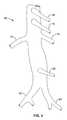
- FIG. 1is an anterior perspective view of an abdominal aorta in the generally vicinity of the renal arteries.
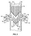
- FIG. 2is a cross-section view of an abdominal aorta taken in the vicinity of the renal arteries showing the general blood flow patterns through the abdominal aorta and the renal arteries.
- FIG. 3is an anterior view of an embodiment of a bifurcated fluid infusion catheter disposed within an abdominal aorta in the vicinity of the renal arteries.
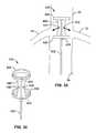
- FIG. 4is a detailed view of one portion of the fluid infusion assembly shown in FIG. 3 in a diastole configuration.
- FIG. 5is a detailed view of the portion of the fluid infusion assembly shown in FIG. 4 , except shows it in a systole configuration.
- FIG. 6is a detailed view of another fluid infusion assembly in a diastole configuration.
- FIG. 7is a detailed view of the fluid infusion assembly shown in FIG. 6 , except shows it in a systole configuration.
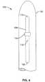
- FIG. 8is a perspective view of another form of bifurcated drug infusion catheter in an expanded configuration.
- FIG. 9is a side plan view of the bifurcated drug infusion catheter shown in FIG. 8 , except shows the catheter in a collapsed configuration.
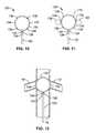
- FIG. 10is an anterior view of another bifurcated drug infusion catheter embodiment with an infusion ring shown in an expanded configuration.
- FIG. 11is an anterior view of the bifurcated fluid infusion catheter embodiment shown in FIG. 10 , shown in one mode of operation discharging medication.
- FIG. 12is an anterior view of the bifurcated drug infusion catheter of FIGS. 10 and 11 , and shows it disposed within an abdominal aorta adjacent to the renal arteries.
- FIG. 13is a left side plan view of the bifurcated drug infusion catheter shown in FIGS. 10-12 , and shows one mode of use disposed within an abdominal aorta adjacent to the renal arteries.
- FIG. 14is an anterior view of the bifurcated drug infusion catheter shown in FIGS. 10-12 , and shows another mode of use disposed within an abdominal aorta immediately above the renal arteries.
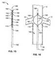
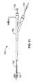
- FIG. 15is a plan view of a fluid infusion catheter with positioning struts according to a further embodiment, and shows the struts in a collapsed configuration.
- FIG. 16is an anterior view of the fluid infusion catheter shown in FIG. 15 , shown with the struts disposed within an abdominal aorta adjacent to the renal arteries in an expanded configuration.
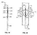
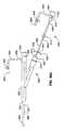
- FIG. 17is a plan view of another fluid infusion catheter with struts shown in a collapsed configuration.
- FIG. 18is an anterior view of the fluid infusion catheter shown in FIG. 17 , and shows the positioning struts disposed within an abdominal aorta adjacent to the renal arteries in an expanded configuration.
- FIG. 19is a plan view of another fluid infusion catheter with positioning struts shown in a collapsed configuration.
- FIG. 20is an anterior view of the fluid infusion catheter of FIG. 19 , and shows the struts disposed within an abdominal aorta adjacent to the renal arteries in an expanded configuration.
- FIG. 21is an anterior view of another fluid infusion catheter with an anchor disposed within an abdominal aorta adjacent to the renal arteries in an expanded configuration.
- FIG. 22is a detailed view of certain aspects of the fluid infusion catheter shown in FIG. 21 .
- FIG. 23is a detailed view of the fluid infusion catheter taken at circle 23 in FIG. 21 .
- FIG. 24is an anterior view of another fluid infusion catheter with a positioning loop disposed within an abdominal aorta immediately above the renal arteries in an extended configuration.
- FIG. 25is a top plan view of the fluid infusion catheter shown in FIG. 24 , and shows the positioning loop is disposed within an abdominal aorta immediately above the renal arteries in an extended configuration.
- FIG. 26is a side plan view of the fluid infusion catheter shown in FIGS. 24-25 , and shows the positioning loop disposed within an abdominal aorta immediately above the renal arteries in an extended configuration.
- FIG. 27is a second side plan view of the fluid infusion catheter shown in FIGS. 24-25 , and shows the positioning loop disposed within an abdominal aorta immediately above the renal arteries in an extended configuration.
- FIG. 28is an anterior view of another fluid infusion catheter with an adjustable positioning loop in a retracted configuration.
- FIG. 29is an anterior view of another fluid infusion catheter with a positioning loop in a partially extended configuration.
- FIG. 30is a anterior view of another fluid infusion catheter with positioning loops in an extended configuration
- FIG. 31is a top plan view of the fluid infusion catheter shown in FIG. 30 , and shows the positioning loops in an extended configuration.
- FIG. 32is a perspective view of another embodiment according to the invention with a fluid infusion catheter cooperating with a flow diverter.
- FIG. 33is an anterior view of the fluid infusion catheter shown in FIG. 32 , and shows the flow diverter disposed within an abdominal aorta adjacent to the renal arteries.
- FIG. 34is a perspective view of another drug infusion catheter with a flow diverter according to a further embodiment.
- FIG. 35is an anterior view of the fluid infusion catheter shown in FIG. 34 , and shows the flow diverter disposed within an abdominal aorta adjacent to the renal arteries.
- FIG. 36is a perspective view of another fluid infusion catheter with a flow diverter according to still a further embodiment.
- FIG. 37is a side plan view of another embodiment of the fluid infusion catheter with flow diverter shown in FIG. 36 .
- FIG. 38is an anterior view of the fluid infusion catheter shown in FIGS. 36-37 , and shows the flow diverter disposed within an abdominal aorta adjacent to the renal arteries.
- FIG. 39is an anterior view of a fluid infusion guide catheter disposed within an abdominal aorta adjacent to the renal arteries.
- FIG. 40is an anterior view of another fluid infusion guide catheter disposed within an abdominal aorta adjacent to the renal arteries.
- FIG. 41is an anterior view of another fluid infusion guide catheter disposed within an abdominal aorta adjacent to the renal arteries.
- FIG. 42is a plan view of the fluid infusion guide catheter shown in FIG. 41 , except showing in another collapsed mode of use.
- FIG. 43is an anterior view of a guide catheter with a coaxial drug infuser disposed within an abdominal aorta adjacent to the renal arteries according to another embodiment.
- FIG. 44is a top plan view of the system shown in FIG. 43 .
- FIG. 45is an anterior view of another guide catheter with a coaxial drug infuser disposed within an abdominal aorta adjacent to the renal arteries.
- FIG. 46is a perspective view of another catheter assembly with a drug infusion introducer sheath disposed within an abdominal aorta adjacent to the renal arteries.
- FIG. 47is a perspective view of another catheter assembly with an infusion balloon disposed within an abdominal aorta adjacent to the renal arteries.
- FIG. 48is a rear perspective view of a self-shaping drug infusion catheter in a first configuration.
- FIG. 49is an anterior view of a self-shaping drug infusion catheter in a second shaped configuration and disposed within an abdominal aorta adjacent to the renal arteries.
- FIG. 50is a top plan view of a self-shaping drug infusion catheter in a shaped configuration and disposed within an abdominal aorta adjacent to the renal arteries
- FIG. 51is a side plan view of a self-shaping drug infusion catheter assembly.
- FIG. 52is a side view of another embodiment of a catheter fluid delivery system with a multilumen sheath.
- FIG. 53is a top section view of the catheter fluid delivery system in FIG. 52 .
- FIG. 54illustrates a proximal coupler system for positioning aortic fluid delivery systems adjunctively with other medical devices.
- FIG. 55illustrates a section view of the proximal coupler system as shown in FIG. 54 .
- FIG. 56Aillustrates a proximal coupler system as shown in FIG. 54 coupled to a local fluid delivery system.
- FIG. 56Billustrates a proximal coupler system as shown in FIG. 56A with a fluid delivery system advanced into an introducer sheath.
- FIG. 57illustrates a proximal coupler system as shown in FIG. 54 through 56B with a fluid infusion device positioned near the renal arteries and a catheter deployed adjunctively in the aorta.
- FIG. 58illustrates a renal therapy system with an introducer sheath system, a vessel dilator, a fluid delivery system and an aortic infusion assembly.
- FIG. 59is a stylized illustration of a double Y assembly with two local fluid delivery systems and an intervention catheter in an aorta system.
- FIG. 3For illustrative purposes the present invention is embodied in the apparatus generally shown in FIG. 3 through FIG. 59 . It will be appreciated that the apparatus may vary as to configuration and as to details of the parts, and that the method may vary as to the specific steps and sequence, without departing from the basic concepts as disclosed herein.
- proximalshould be understood to mean locations on a system or device relatively closer to the operator during use
- distalshould be understood to mean locations relatively further away from the operator during use of a system or device.
- the disclosed material delivery systemswill include a fluid delivery assembly, a proximal coupler assembly and one or more elongated bodies, such as tubes or catheters.
- elongated bodiessuch as tubes or catheters.
- These elongated bodiesmay contain one or more lumens and generally consist of a proximal region, a mid-distal region, and a distal tip region.
- the distal tip regionwill typically have means for delivering a material such as a fluid agent.
- Radiopaque markers or other devicesmay be coupled to the specific regions of the elongated body to assist introduction and positioning.
- the material delivery systemis intended to be placed into position by a physician, typically either an interventionalist (cardiologist or radiologist) or an intensivist, a physician who specializes in the treatment of intensive-care patients.
- a physiciantypically either an interventionalist (cardiologist or radiologist) or an intensivist, a physician who specializes in the treatment of intensive-care patients.
- the physicianwill gain access to a femoral artery in the patient's groin, typically using a Seldinger technique of percutaneous vessel access or other conventional method.
- the inventionis also related to subject matter disclosed in other Published International Patent Applications as follows: WO 00/41612 to Libra Medical Systems, published Jul. 20, 2000; and WO 01/83016 to Libra Medical Systems, published Nov. 8, 2001.
- the disclosures of these Published International Patent Applicationsare also herein incorporated in their entirety by reference thereto.
- an abdominal aortais shown and is generally designated 10 .
- a right renal artery 12 and a left renal artery 14extend from the abdominal aorta 10 .
- a superior mesenteric artery 16extends from the abdominal aorta 10 above the renal arteries 12 , 14 .
- a celiac artery 18extends from the abdominal aorta 10 above the superior mesenteric artery 16 .
- FIG. 1also shows that an inferior mesenteric artery 20 extends from the abdominal aorta 10 below the renal arteries 12 , 14 . Further, as shown in FIG.
- the abdominal aorta 10branches into a right iliac artery 22 and a left iliac artery 24 . It is to be understood that each embodiments of the present invention described in detail below can be used to deliver a drug or other fluid solution locally into the renal arteries 12 , 14 . Each of the below-described embodiments can be advanced through one of the iliac arteries 22 , 24 and into the abdominal aorta 10 until the general vicinity of the renal arteries 12 , 14 is reached.
- FIG. 2shows a schematic cross-section of the abdominal aorta 10 taken in the immediate vicinity of the renal arteries 12 , 14 .
- FIG. 2shows the natural flow patterns through the abdominal aorta 10 and the natural flow patterns from the abdominal aorta 10 into the renal arteries 12 , 14 .
- the flow down the abdominal aorta 10maintains a laminar flow pattern.
- the flow stream near the middle of the abdominal aorta 10as indicated by dashed box 30 , continues down the abdominal aorta 10 , as indicated by arrows 32 , and does not feed into any of the side branches, e.g., the renal arteries 12 , 14 .
- a drug solution infusion down the middle of the abdominal aorta flow streamcan be ineffective in obtaining isolated drug flow into the renal arteries 12 , 14 .
- the flow stream along an inner wall 34 of the abdominal aorta 10contains a natural laminar flow stream into the branching arteries, e.g., the renal arteries 12 , 14 , as indicated by arrows 40 , 42 .
- the flow stream 32is of a higher velocity than flow stream 40 along wall 34 of aorta 10 . It is to be understood that near the boundaries of dashed box 36 , 38 with dashed box 30 the flow stream can contain flow streams into the branching arteries 12 , 14 —as well as down the abdominal aorta 10 .
- the ostia of renal arteries 12 , 14are positioned to receive substantial blood flow from the blood flow near the posterior wall 34 of aorta 10 as well as the side walls.
- blood flow 40 in dashed boxes 36 , 38 togetheris greater than blood flow 32 in dashed box 30 when along the posterior wall of aorta 10 relative to blood flow in the center of aorta 10 as shown in FIG. 2 .
- drug infusion above renal arteries 12 , 14 and along the posterior wall of aorta 10will be effective in reaching renal arteries 12 , 14 .
- a deviceas described in detail below, that is adapted to selectively infuse a drug solution along the side wall or posterior wall of the abdominal aorta 10 instead of within the middle of the abdominal aorta 10 or along the anterior wall.
- the bifurcated drug infusion catheter 50includes a central catheter body 51 that splits into a first bifurcated portion 52 and a second bifurcated portion 54 .
- Each bifurcated portion 52 , 54includes a free end 56 in which an infusion port 58 is formed.
- Each free end 56further includes a radio-opaque marker band 59 .
- an infusion assembly 60is attached to the free end 56 of each bifurcated portion 52 , 54 around the infusion port 58 . Details concerning the construction of each infusion assembly 60 are described below.
- the bifurcated drug infusion catheter 50 shown in FIG. 3places a bifurcated portion 52 , 54 on the inner wall 34 of the abdominal aorta 10 generally immediately upstream from the level of the renal arteries 12 , 14 .
- the infusion ports 58are positioned inside an infusion assembly 60 , described below, that releases a drug solution during the systolic phase of blood flow in which the blood flow within the abdominal aorta 10 is more predictable and more closely tracks the wall 34 of the abdominal aorta 10 into the renal arteries 12 , 14 , as indicated by arrows 62 .
- the infusion of a drug solution from the bifurcated portions 52 , 54 of the bifurcated drug infusion catheter 50when positioned adjacent to the inner wall 34 of the abdominal aorta 10 , results in a greater percentage of the drug solution entering the renal arteries 12 , 14 than systemic injection.
- “mixing” into the center of the abdominal aorta 10can still take place, e.g., during the diastolic phase of blood flow through the abdominal aorta 10 .
- releasing a drug solution from a properly positioned bifurcated drug infusion catheter 50 during the systolic phasecan result in a majority of the drug solution flowing into the renal arteries 12 , 14 .
- a “passive” infusion assemblyallows the bifurcated drug infusion catheter 50 to work in a beneficial manner with improved efficiency and reduced complexity. While it is technically feasible to pulse the injection of a drug with an electro mechanical device driven by an ECG signal it is beyond the scope of the desired level of complexity desired.
- the infusion assembly 60includes a collapsible tube 64 having a proximal end 66 and a distal end 68 . Further, a one way check valve 70 is installed in the distal end 68 of the collapsible tube 64 .
- FIG. 4shows the infusion assembly 60 in the diastole configuration in which the one way check valve 70 is closed.
- a drug solution 74 trickling from the infusion port 58can collect in the tube 64 where it is prevented from mixing into the middle of the abdominal aorta 10 .
- the infusion assembly 60moves to the systole configuration, wherein blood flow opens the one way check valve 70 and the drug solution 74 flows out of the infusion assembly 60 , along the wall 34 of the abdominal aorta 10 , and into the renal artery 14 .
- FIG. 6 and FIG. 7show another embodiment of an infusion assembly, designated 80 , that can be used in conjunction with the bifurcated drug infusion catheter 50 shown in FIG. 3 .
- the infusion assembly 80includes a collapsible sock 82 having a distal end 84 and a proximal end 86 .
- the infusion assembly 80is the diastole configuration wherein the drug solution 74 from the infusion port 58 can collect in the collapsible sock 82 .
- the drug solution 74is prevented from mixing into the middle of the abdominal aorta 10 .
- systoleas indicated by arrow 90 in FIG.
- the infusion assembly 80moves to the systole configuration, wherein the blood flow causes the collapsible sock 82 to collapse and the drug solution 74 flows out of the infusion assembly 80 , along the wall 34 of the abdominal aorta 10 , and into the renal artery 14 .
- the bifurcated drug infusion catheter 50shown in FIG. 3 , can be used with either of the above-described infusion assemblies 60 , 80 .
- the bifurcated drug infusion catheter 50can be introduced through a long 8 or 9 French (Fr) diameter introducer sheath positioned near the renal arteries 12 , 14 . Thereafter, partially withdrawing the introducer sheath can expose the free ends 56 of the bifurcated portions 52 , 54 of the bifurcated drug infusion catheter 50 until separation can be detected, e.g., at approximately one-half (1 ⁇ 2) of the diameter of the abdominal aorta 10 .
- FrFrench
- the bifurcated drug infusion catheter 50can be rotated back and forth until the marker bands 59 are in the most lateral position, i.e., when the distance between the marker bands 59 appears to be the greatest. Then, the longitudinal position of the bifurcated drug infusion catheter 50 can be fine tuned.
- a usere.g., a physician, can continue to withdraw the introducer sheath until the free ends 56 of the bifurcated drug infusion catheter 50 are in contact with the inner wall 34 of the aorta 10 .
- the bifurcated drug infusion catheter 50can be held in place within the abdominal aorta 10 by a spring force separating the bifurcated portions 52 , 54 of the bifurcated drug infusion catheter 50 . It can be further appreciated that each of the embodiments shown in FIGS. 3-7 are relatively easy to position, present limited surface area, and minimize flow stagnation. Moreover, upstream interventions may be performed, e.g. PCA.
- the bifurcated drug infusion catheter 100includes a central catheter tube 102 .
- catheter tube 102is multilumen.
- a first infusion tube 104 and a second infusion tube 106are coupled to and extend from the central catheter tube 102 at approximately one-hundred and eighty degrees (180°) from each other.
- Each infusion tube 104 , 106includes a proximal end 108 and a distal end 110 .
- each infusion tube 104 , 106are coupled to the central catheter tube 102 and the proximal ends 108 enter catheter tube 102 and continue proximally to a proximal coupler assembly (not shown). It is to be understood that during drug infusion, a drug solution can flow from the central catheter tube 102 and through each infusion tube 104 , 106 , e.g., from the proximal end 108 to the distal end 110 , or from the distal end 110 to the proximal end 108 , but drug solution principally exits through ports 112 .
- FIG. 8 and FIG. 9show the infusion tubes 104 , 106 in an expanded configuration and a retracted configuration respectively.
- the infusion tubes 104 , 106are advanced distally from a proximal coupler assembly (not shown) causing each infusion tube 104 , 106 to bow outward in the expanded configuration shown in FIG. 8 .
- infusion tubes 104 , 106are retracted proximally from a proximal coupler assembly (not shown), they straighten in the retracted configuration shown in FIG. 9 .
- FIG. 8 and FIG. 9further show that each infusion tube 104 , 106 is formed with an infusion port 112 from which a drug solution can flow during drug infusion. Moreover, each infusion tube 104 , 106 includes a marker band 114 to assist in properly positioning the bifurcated catheter tube 100 within the abdominal aorta 10 ( FIG. 1 ).
- FIG. 8shows the bifurcated drug infusion catheter 100 in the expanded configuration.
- the infusion tubes 104 , 106can bow away from the central catheter tube 102 in order to provide drug infusion nearer to the inner wall 34 ( FIG. 1 ) of the abdominal aorta 10 ( FIG. 1 ) and maintain positioning within aorta 10 .
- the infusion tubes 104 , 106are retracted against the central catheter tube 102 .
- the bifurcated drug infusion catheter 100can be inserted into the abdominal aorta 10 , e.g., from the right iliac artery 22 or the left iliac artery 24 .
- the infusion tubes 104 , 106can retract and aid in removal of the bifurcated drug infusion catheter 100 from the abdominal aorta 10 ( FIG. 1 ).
- one or more additional struts or tubesmay be added to catheter 100 to position or stabilize the infusion tubes 104 , 106 near the renal arteries. It is further understood that the additional struts may be made of different materials than the infusion tubes 104 , 106 .
- FIG. 10 through FIG. 14show various modes according to a further embodiment of a bifurcated fluid infusion catheter, generally configured as an infusion ring, and designated 120 .
- FIGS. 10 through 14show that the bifurcated drug infusion catheter 120 includes a central catheter tube 122 that defines a proximal end (not shown) and a distal end 124 .
- An infusion ring 126is attached to the distal end 124 of the central catheter tube 122 . More specifically, the infusion ring 126 includes a first end 128 and a second end 130 that are attached to the distal end 124 of the central catheter tube 122 .
- a drug solutioncan flow from the central catheter tube 122 into the infusion ring 126 via the first end 128 and second end 130 thereof.
- the infusion ring 126is preferably formed with a first infusion port 132 and a second infusion port 134 .
- the infusion ports 132 , 134are located along the infusion ring 126 at approximately one-hundred and eighty degrees (180°) from each other.
- FIG. 10 through FIG. 14further show that the infusion ring 126 includes plural radio-opaque marker bands 136 .
- a drug solution 138can flow from the infusion ports 132 , 134 , e.g., at or above the renal arteries 12 , 14 .
- the infusion ring 126can be made of a material having a radial strength sufficient enough to maintain the infusion ring 126 against the inner wall 34 of the abdominal aorta 10 , as shown in FIG. 12 .
- the infusion ring 126is sufficiently flexible to allow it to become slightly squashed, i.e., elliptical, during insertion.
- the infusion ring 126can be radio-opaque in order to aid in locating and positioning the infusion ring 126 within the abdominal aorta 10 .
- the marker bands 138can aid in positioning the infusion ports 132 , 134 .
- the location of the infusion ring 126can be exactly at the renal arteries 12 , 14 , i.e., with the infusion ports 132 , 134 aligned with the renal arteries 12 , 14 , in order to maximize drug infusion into the renal arteries 12 , 14 .
- the infuser ring configurationis it is easy to position, visualize, advance and retract in the aorta. Another benefit is it is low profile. This allows guide catheters and guide wires to pass and reduces thrombus formation due to flow disruption.
- the low profile low bulk of the infusion ringallows insertion using smaller diameter sheaths.
- the infusion ringis made of a memory shape material such as Nitinol tubing, vertically oriented, and fed through an introducer sheath in a collapsed state to its position near the renal arteries.
- the infusion ringis a flexible free form material and a pull wire is extended through the infusion ring to control expansion of the ring and does not require placement by an introducer sheath.
- This configurationalso allows rotational positioning in a contracted state without the risk of vessel trauma.
- additional homodynamic aidswings, spoilers, flow directors, etc.
- wings, spoilers, flow directors, etc.can be coupled on the Nitinol loop in areas which cause limited flow disruption (i.e. simply against the aortas' posterior wall).
- FIG. 13shows a configuration where the bifurcated drug infusion catheter 120 is installed within the abdominal aorta 10 and the central catheter tube 122 rests against the back of the abdominal aorta 10 while the infusion ring 126 is at an angle with respect to the abdominal aorta 10 .
- This configurationis beneficial to allow guide catheters and guide wires to pass through the infusion ring 126 .
- the infusion ring 126can be placed above the renal arteries 12 , 14 with the infusion ports 132 , 134 slightly distanced from the renal arteries 12 , 14 . Due to the flow pattern discussed above in conjunction with FIG. 2 , no vessel or side branch can disturb the flow stream above the renal arteries 12 , 14 . With drug infusion along the wall 34 of the abdominal aorta 10 , other branches extending from the abdominal aorta 10 cannot disturb the flow streams into the renal arteries 12 , 14 .
- a further embodimentis a drug infusion catheter with positioning struts for positioning the catheter within an abdominal aorta is shown and is generally designated 150 .
- the drug infusion catheter 150includes an outer tube 152 that defines a proximal end (not shown) and a distal end 154 .
- a central support tube 156extends from within the outer tube 152 beyond the distal end 154 thereof.
- a tip 158is provided at the end of the central support tube 156 .
- FIG. 15 and FIG. 16show that the drug infusion catheter 150 includes a first collapsible strut 160 and a second collapsible strut 162 slidably disposed within the outer tube 152 .
- Each collapsible strut 162includes a proximal end (not shown) and a distal end 164 and the distal end 164 of each collapsible strut 162 is attached to the tip 158 .
- proximal endnot shown
- distal end 164 of each collapsible strut 162is attached to the tip 158 .
- each collapsible strut 160 , 162includes an infusion port 166 . Further, each collapsible strut 160 , 162 includes a first marker band 168 above the infusion port 166 and a second marker band 170 below the infusion port 166 . Preferably, each marker band is radio-opaque to assist in positioning the drug infusion catheter 150 within the abdominal aorta 10 .
- FIG. 15shows the drug infusion catheter 150 in the collapsed configuration, i.e., with the collapsible struts 160 , 162 that form positioning struts in the collapsed configuration.
- the drug infusion catheter 150can be inserted into to the right or left iliac artery 22 , 24 ( FIG. 1 ) and fed into the abdominal artery 10 until it is in proper position near the renal arteries 12 , 14 .
- the collapsible struts 160 , 162can be advanced forward relative to the outer tube 152 causing them to release from the central support tube 156 .
- the collapsible struts 160 , 162can be advanced forward until they establish the expanded configuration shown in FIG. 16 .
- the infusion ports 166are positioned immediately adjacent to the renal arteries 12 , 14 and can release a drug solution directly into the renal arteries 12 , 14 .
- the drug infusion catheter 150can be placed so that the drug solution is infused immediately above the renal arteries 12 , 14 along the wall 34 of the abdominal aorta 10 . After a specified dwell time within the abdominal aorta 10 , the drug infusion catheter 150 can be returned to the collapsed configuration and withdrawn from the abdominal aorta 10 .
- FIG. 17 and FIG. 18another embodiment of a drug infusion catheter with positioning struts is shown.
- FIG. 17 and FIG. 18shows that the drug infusion catheter 150 can include a third collapsible strut 172 and a fourth collapsible strut 174 . Accordingly, when expanded as described above, the drug infusion catheter 150 with the four collapsible struts 160 , 162 , 172 , 174 resembles a cage.
- FIG. 19 and FIG. 20show another embodiment of a drug infusion catheter with positioning struts for positioning the catheter within an abdominal aorta, generally designated 200 .
- the drug infusion catheter 200includes an outer tube 202 having a proximal end (not shown) and a distal end 204 .
- a first collapsible strut 206 , a second collapsible strut 208 , a third collapsible strut 210 , and a fourth collapsible strut 212are established by the outer tube 202 immediately adjacent to the distal end 204 of the outer tube 202 .
- a central support hypotube 214is slidably disposed within the outer tube 202 .
- a distal end (not shown) of the central support hypotube 214is affixed within the distal end 204 of the outer tube 202 . Accordingly, as intended by the present embodiment, when the central support hypotube 214 is retracted proximally in the outer tube 202 , the struts 206 , 208 , 210 , 212 expand and create a cage configuration that can secure the drug infusion catheter 200 , e.g., within the abdominal aorta 10 near the renal arteries 12 , 14 .
- FIG. 19 and FIG. 20show that the first strut 206 and the second strut 208 are each formed with an infusion port 216 . Additionally, a first marker band 218 is disposed above the infusion ports 216 along each strut. And, a second marker band 220 is disposed below the infusion ports 216 along each strut. During use, a drug solution can be released from the infusion ports 216 formed in the first and second struts 206 , 208 . It can be appreciated that the third and fourth struts 210 , 212 can also establish infusion ports and can further include marker bands, as described above. It can also be appreciated that drug infusion catheter 200 may be practiced with only a first and a second struts 206 , 208 to present a lower profile.
- FIG. 19shows the drug infusion catheter 200 in the collapsed configuration.
- the drug infusion catheter 200can be inserted into to the right or left iliac artery 22 , 24 ( FIG. 1 ) and fed into the abdominal artery 10 until it is in proper position near the renal arteries 12 , 14 .
- the central support hypotube 214is retracted proximally in outer tube 202 causing the struts 206 , 208 , 210 , 212 to release from the central support tube 202 and bow outward.
- the central support hypotube 214can be retracted proximally, as described above, until the struts 206 , 208 , 210 , 212 establish the expanded configuration shown in FIG. 20 .
- the infusion ports 216are positioned immediately adjacent to the renal arteries 12 , 14 and can release a drug solution directly into the renal arteries 12 , 14 .
- the drug infusion catheter 200can be placed so that the drug solution is infused immediately above the renal arteries 12 , 14 along the wall 34 of the abdominal aorta 10 .
- the drug infusion catheter 200can be returned to the collapsed configuration and withdrawn from the abdominal aorta 10 .
- FIG. 21another embodiment of a drug infusion catheter with an anchor for positioning the catheter within an abdominal aorta is shown and is generally designated 250 ,
- FIG. 21shows the drug infusion catheter 250 installed within an abdominal aorta 10 in the vicinity of the renal arteries 12 , 14 .
- the drug infusion catheter 250includes a central catheter tube 252 having a proximal end (not shown) and a distal end 254 .
- a hollow stent 256is attached to the distal end 254 of the central catheter tube 252 and a drug solution can flow from the central catheter tube 252 into the hollow stent 256 .
- the hollow stent 256is formed partially or entirely of hollow hypo tubing, though other variations of elastomeric tubing may be used.
- the stent 256can be punctured or otherwise formed with plural infusion ports 258 along the outer surface of the stent 256 .
- the drug infusion catheter 250can be positioned, and expanded, within the abdominal aorta 10 , as shown in FIG. 21 , such that the stent 256 is anchored in the vicinity of the renal arteries 12 , 14 .
- a drug solutioncan be released from the hollow stent 256 via the infusion ports 258 directly into the renal arteries 12 , 14 .
- the stent 256can form an expandable open-mesh structure that can have an element, or a few elements, that cross the renal ostia without disrupting the blood flow to the renal arteries 12 , 14 . It is to be understood that the ability to deploy and recapture the stent 256 can be accomplished using a number of methods apparent to those of ordinary skill in the art based on review of this disclosure, e.g., by suitably modifying the methods typically employed for deploying and recapturing temporary vena cava filters or retractable stents.
- FIG. 24 through FIG. 28another embodiment of a drug infusion catheter with positioning loops for positioning the catheter within an abdominal aorta is shown and is generally designated 300 .
- FIG. 24 through FIG. 28show that the drug infusion catheter 300 includes a central catheter tube 302 that defines a proximal end (not shown) and a distal end 304 .
- a generally vertically oriented positioning loop 306extends from the distal end 304 of the central catheter tube 302 .
- the positioning loop 306is made from a memory metal, e.g., nickel-titanium (NiTi).
- the positioning loop 306can be held in a pre-determined position via shape setting or it can be in a free-form shape and held in a final diameter via the inner wall 34 of the abdominal aorta 10 . As specifically shown in FIG. 26 and FIG. 27 , the positioning loop 306 can sufficiently hold the drug infusion catheter 300 in place regardless of the diameter of the abdominal aorta 10 e.g. as shown in the smaller and larger diameter aortas of FIG. 26 and FIG. 27 , respectively.
- the drug infusion catheter 300can include a pull wire 308 that extends from a port 310 formed in the central catheter tube 302 .
- the pull wire 308is attached to the positioning loop 306 and can be used to control the expansion and contraction of the positioning loop 306 without the need for an external sheath.
- FIG. 28specifically shows the positioning loop 306 in a fully retracted configuration that can be used when inserting or withdrawing the drug infusion catheter 300 .
- FIG. 24 . through 28further show that the central catheter tube 302 is formed with a first infusion port 312 and a second infusion port 314 .
- a drug solutioncan exit the central catheter tube 302 and flow into the renal arteries 12 , 14 as indicated by arrow 316 and 318 .
- the drug infusion catheter 300 shown in FIG. 24 through 28can allow rotational position adjustment and vertical position adjustment without the risk of trauma to the abdominal aorta 10 .
- the positioning loop 306can be retracted numerous ways to allow atraumatic rotation. And, since there are not any protruding or traumatic edges to catch aortic tissue on, the drug infusion catheter 300 can be moved up and down without retracting the positioning loop 306 .
- positioning loop 306is free form without pull wire 310 . It can be appreciated that positioning loop 306 can be made of a shape-memory alloy, such as NitinolTM, and advanced through the distal end 304 of catheter 300 for positioning and retracted for insertion and removal.
- the present embodimentrecognizes that experimental observations have shown that a drug solution can flow into the renal arteries 12 , 14 naturally, provided the drug infusion is undertaken above the renal arteries 12 , 14 and above or closely adjacent to the posterior aspect of the inner wall 34 of the abdominal aorta 10 .
- the positioning loop 306can easily position the central catheter tube 302 against the posterior of the inner wall 34 of the abdominal aorta 10 and does not require a flow diverter, e.g., a balloon or membrane, to maximize drug infusion to the renal arteries 12 , 14 . As such, the possibility of thrombus formation due to the disruption of blood flow is minimized.
- the drug infusion catheter 300can easily allow various guide catheters and guide wires to pass therethrough and that passage can have minimal effect on the tactile feedback or other performance aspects of the adjunctive catheters that are typically used in a percutaneous coronary intervention (PCI).
- PCIpercutaneous coronary intervention
- FIG. 29shows another embodiment of a drug infusion catheter with a positioning loop for positioning the catheter within an abdominal aorta, generally designated 330 .
- the drug infusion catheter 330includes a central catheter tube 332 having a proximal end (not shown) and a distal end 334 .
- a positioning loop 336extends from the distal end 334 of the central catheter tube 332 .
- the drug infusion catheter 330can include a pull wire 338 that extends from a port 340 formed in the central catheter tube 332 .
- the pull wire 338is attached to the positioning loop 306 and can be used to retract the positioning loop 336 during insertion or withdrawal of the drug infusion catheter 330 .
- a flow director 342is affixed to the distal end 334 of the central catheter tube 332 .
- the flow director 342is formed with a bifurcated (e.g. a T-shaped) infusion passage 344 that directs the flow of a drug solution from an infusion port (not shown) formed in the distal end 334 of the central catheter tube 332 in two opposing directions—as indicated by arrow 346 and arrow 348 .
- the drug infusion catheter 360includes a central catheter tube 362 that defines a proximal end (not shown) and a distal end 364 .
- a first positioning wire 366 and a second positioning wire 368extend from a port 370 formed in the central catheter tube 362 .
- Each positioning wire 366 , 368defines a proximal end (not shown) and a distal end 372 .
- the distal end 372 of each positioning wire 366 , 368is attached to the distal end 364 of the central catheter tube 362 .
- the positioning wires 366 , 368extend through the entire length of the central catheter tube 370 and can be used to establish an adjustable positioning loop. It can be appreciated that the adjustable positioning loop can be adjusted by extending or retracting the positioning wires 366 , 368 through the port 370 in the central catheter tube 363 .
- the drug infusion catheter 400includes a central catheter tube 402 that defines a proximal end (not shown) and a distal end 404 .
- a ring 406is attached to the distal end 404 of the central catheter tube 402 .
- a generally cylindrical curtain 408extends from the ring 406 .
- the curtain 408is made from expanded polytetrafluoroethylene (ePTFE) or any material with similar characteristics well known in the art.
- the overall length of renal flow isolator 400is about 1.5 cm.
- FIG. 32 and FIG. 33further show an infusion tube 410 that extends bi-directionally from the central catheter tube 402 .
- a first infusion port 412 and a second infusion port 414are established on the outside of curtain 408 by the infusion tube 410 .
- the single ring 406allows for sizing to the abdominal aorta 10 to maintain the infusion ports 412 , 414 along the inner wall 34 of the abdominal aorta 10 .
- the configuration of the drug infusion catheter 400 shown in FIG. 32 and FIG. 33reduces the amount of stagnant blood around the drug infusion catheter 400 and thereby, minimizes the blood clotting thereon. This configuration also puts the drug along the aortic wall.
- central catheter tube 402has an offset that is a slight S shape (not shown) and positions renal flow diverter 400 off the aorta wall.
- FIG. 34 and FIG. 35show a further embodiment of a drug infusion catheter with a flow isolator, generally designated 430 .
- the drug infusion catheter 430includes a central catheter tube 432 with a mid distal position 433 and a distal end 434 .
- An upper ring 436is attached to the distal end 434 of the central catheter tube 432 .
- a lower ring 438is attached to the catheter tube 432 at mid distal position 433 and at a distance slightly spaced from the upper ring 436 .
- FIG. 34 and FIG. 35further show catheter tube 432 connecting the upper ring 436 to the lower ring 438 .
- the catheter tube 432 between mid distal position 433 and distal end 434is covered with a layer of fabric 440 , such as ePTFE, extending from upper ring 436 to lower ring 438 .
- fabric 440such as ePTFE
- the orientation of fabric 440reduces the amount of stagnant blood collecting around the drug infusion catheter 430 and thereby, minimizes the blood clotting thereon.
- the overall length of drug infusion catheteris about 2 cm.
- a first infusion port 442 and a second infusion port 444are established in a mid section of fabric 440 of the drug infusion catheter 430 .
- the upper ring 436 and the lower ring 438ensure that the infusion ports 442 , 444 are placed along side of the inner wall 34 of the abdominal aorta 10 .
- the preferred position of the drug infusion catheter 430 within the abdominal aorta 10is such that the infusion ports 442 , 444 are closest to the posterior of the abdominal aorta 10 .
- central catheter tube 432has an offset that is a slight S shape (not shown) and positions drug infusion catheter 430 off the aorta wall.
- the drug infusion catheter 460includes a central catheter tube 462 that defines a proximal end (not shown) and a mid distal position 464 .
- a ring 466is attached near the mid distal position 464 of the catheter tube 462 .
- FIG. 36 through FIG. 38further show central catheter tube 462 with an offset near mid distal position 464 and a sail 470 attached to the distal end 468 that extends partially around the perimeter of the ring 466 .
- the sail 470forms a semi-conical shape between the mast 468 and the ring 466 .
- the sail 470is made from ePTFE, though other suitable materials may be used or applied. It can be appreciated that the semi-conical shape of the sail 470 and the material from which it is constructed reduces the amount of stagnate blood around the drug infusion catheter 460 and as such, the chance of blood clots forming around the drug infusion catheter 460 is minimized.
- FIG. 36 and FIG. 38show a first infusion port 472 and a second infusion port 474 established along the catheter tube 462 between distal end 468 and ring 466 .
- the ring 466maintains the position of the drug infusion catheter 460 against the inner wall 34 of the abdominal aorta 10 .
- the sail 470is designed to divert blood flow, and thus, the flow of a drug solution trickling from the infusion ports 472 , 474 , into the renal arteries 12 , 14 .
- the preferred position of the drug infusion catheter 460 within the abdominal aorta 10is such that the infusion ports 472 , 474 are closest to the posterior of the abdominal aorta 10 .
- FIG. 39shows one embodiment a drug infusion guide catheter, designated 500 , that can be placed within an abdominal aorta 10 in the general vicinity just above the renal arteries 12 , 14 .
- the drug infusion guide catheter 500includes an infusion port 502 formed in the outer wall of the drug infusion guide catheter 500 .
- a drug solutioncan be released from the drug infusion guide catheter 500 via the infusion port 502 .
- the renal blood flow (see FIG. 2 ) to each renal artery 12 , 14is about 15 percent of total aortic blood flow for a total of about 30 percent. With no change in blood flow, about 30 percent of drug solution released from infusion port 502 will reach renal arteries 12 , 14 .
- the drug infusion guide catheter 500is at least formed with two lumens therein, i.e., a first relatively larger lumen for the exchange of devices and a second relatively smaller lumen for drug infusion. Accordingly, as intended by the present embodiment, the requirement for a secondary device, in addition to the drug infusion guide catheter 500 , to infuse drugs and medication to the renal arteries 12 , 14 during a PCI is obviated.
- FIG. 40shows another embodiment of a drug infusion guide catheter, generally designated 520 .
- the drug infusion guide catheter 520can be inserted into the abdominal aorta 10 , e.g., via the left or right iliac artery 22 , 24 ( FIG. 1 ), until it is in the vicinity of the renal arteries 12 , 14 .
- FIG. 40shows that the drug infusion guide catheter 520 includes an infusion port 522 that is formed in the outer wall of the drug infusion guide catheter 520 . It can be appreciated that a drug solution can be released from the drug infusion guide catheter 520 via the infusion port 522 .
- the drug infusion guide catheter 520further includes a balloon 524 that can be inflated to divert blood flow into the renal arteries 12 , 14 .
- the balloon 524can be made from silicon, nylon, PEBAX, polyurethane, or any other similar compliant or semi-compliant material well known in the art. Moreover, the balloon 524 can be inflated such that it engages the inner wall 34 of the abdominal aorta 10 or it can be inflated such that it is smaller than the diameter of the inner wall 34 of the abdominal aorta 10 so that it will not entirely block the flow of blood through the abdominal aorta 10 . Basically, the size of the balloon 524 can be easily varied by varying the inflation pressure of the balloon 524 thereby affecting the blood flow past renal arteries 12 , 14 .
- the drug infusion guide catheter 520 shown in FIG. 40is preferably formed with three lumens therein.
- the drug infusion guide catheter 520can include a first relatively large lumen for the exchange of devices, a second relatively small lumen for drug infusion, and a third relatively small lumen for balloon inflation.
- a drug solution in the abdominal aorta 10e.g., from the drug infusion guide catheter 520 , during systole, as indicated by arrow 526 and arrow 528 .
- the drug solutioncan flow in a generally downward direction from the infusion port 522 , as indicated by arrow 530 and arrow 532 , and into the right renal artery 12 and the left renal artery 14 , as indicated by arrow 534 and arrow 536 .
- the balloon 524maximizes the flow of the drug solution into the renal arteries 12 , 14 .
- a counter pulsation of the balloon relative to the systolic/diastolic cyclemay be used to enhance performance.
- FIG. 41 and FIG. 42another embodiment of a drug infusion guide catheter is shown and is generally designated 550 .
- the drug infusion guide catheter 550can be advanced into the abdominal aorta 10 , e.g., via the left or right iliac artery 22 , 24 ( FIG. 1 ), until it is in the vicinity of the renal arteries 12 , 14 .
- FIG. 41shows that the drug infusion guide catheter 550 includes an infusion port 552 that is formed in the outer wall of the drug infusion guide catheter 550 . It can be appreciated that a drug solution can be released from the drug infusion guide catheter 550 via the infusion port 552 .
- the drug infusion guide catheter 550further includes a flow diverter 554 that can be expanded to divert blood flow into the renal arteries 12 , 14 .
- FIG. 41shows that the flow diverter 554 includes a membrane 556 that can be expanded by a frame 558 —much like a basket or an umbrella.
- the membrane 556can be made from nylon, PEBAX, polyurethane, low density PTFE or any other similar material with low porosity to allow for blood diffusion through the membrane 556 .
- the membrane 556can be lazed or otherwise formed with plural holes 560 of varying diameter, e.g., from twenty-five micrometers to five-hundred micrometers (25 ⁇ m-500 ⁇ m) to allow blood flow through the material film.
- membrane 556can be a wire mesh or stent-like devices.
- the frame 558is preferably made from a memory metal, e.g., NiTi, to allow for conformability to the aorta and pre-shaped capabilities. It can be appreciated that the flow diverter 554 can be expanded such that it engages the inner wall 34 of the abdominal aorta 10 .
- the flow diverter 554can be collapsed within an outer sheath 562 disposed around the drug infusion guide catheter 550 . Once the drug infusion guide catheter 550 is in place within the abdominal aorta 10 , the sheath 562 can be withdrawn causing the flow diverter 554 to be deployed near the renal arteries 12 , 14 .
- the drug infusion guide catheter 550 shown in FIG. 41is preferably formed with at least two lumens therein.
- the drug infusion guide catheter 550can include a first relatively large lumen for the exchange of devices, and a second relatively small lumen for drug infusion.
- a drug solution in the abdominal aorta 10e.g., from the drug infusion guide catheter 550 , during systole, as indicated by arrow 564 and arrow 566 shown in FIG. 41 .
- the drug solutioncan flow in a generally downward direction from the infusion port 552 , as indicated by arrow 568 and arrow 570 , and into the right renal artery 12 and the left renal artery 14 , as indicated by arrow 572 and arrow 574 .
- the flow diverter 554when deployed, maximizes the flow of the drug solution into the renal arteries 12 , 14 .
- FIG. 43shows that the guide catheter with a coaxial drug infuser 600 includes a central catheter tube 602 around which a generally ring shaped, drug infuser 604 is slidably disposed.
- a drug infusion catheter 606extends from the drug infuser 604 and can be used to supply a drug solution to the drug infuser 604 .
- FIG. 44shows that an annular space can be established between the drug infuser 604 and the central guide catheter 602 .
- An infusion port(not shown) can be established in drug infuser 604 , and is fluidly connected to drug infusion catheter 606 .
- FIG. 43shows that a drug solution can exit the drug infuser 604 via the top of the drug infuser 604 , as indicated by arrow 610 and arrow 612 .
- the drug solutioncan also exit the drug infuser 604 at the bottom of the drug infuser 604 , as indicated by arrow 614 and arrow 616 .
- the bottom of drug infuser 604fits closely around central catheter tube 602 and drug solution flows preferably out the top as shown by arrow 610 , 612 .
- the top of drug infuser 604fits closely around central catheter tube 602 and drug solution flows preferably out the bottom as shown by arrow 614 , 616 During systole, indicated by arrow 618 and arrow 620 , the drug solution can flow into the right and left renal arteries 12 , 14 , as indicated by arrow 622 and arrow 624 .
- drug infuser 604provides drug solution preferentially to the lower extremities. While a ring shape is shown, other embodiments, e.g. a partial ring, are contemplated for slideable coupling for independent positioning.
- FIG. 45another embodiment of a guide catheter with a coaxial drug infuser is shown.
- the guide catheter with a coaxial drug infuseris identical to the embodiment shown in FIG. 43 and FIG. 44 .
- the guide catheter with a coaxial drug infuser shown in FIG. 45further includes a balloon 626 fluidly connected to the drug infusion catheter 606 .
- the balloon 626can be inflated to divert the flow of blood therearound and further increase the flow of the drug solution into the renal arteries 12 , 14 .
- FIG. 46shows a catheter assembly with a drug infusion introducer sheath, generally designated 640 .
- the catheter assembly 640includes a central guide catheter 642 that is inserted through the right iliac artery 22 and advanced until it is within the abdominal aorta 10 .
- FIG. 46further shows a drug infusion introducer sheath 644 around the central guide catheter 642 .
- the drug infusion introducer sheath 644defines a proximal end 646 and a distal end 648 .
- the proximal end 646 of the introducer sheath 644is attached to a catheter introducer hub 650 that can be used to advance the introducer sheath 644 into aorta 10 .
- the drug infusion introducer sheath 644can be advanced until the distal end 648 of the introducer sheath 644 is at or above the renal arteries 12 , 14 .
- an annular infusion port 652is established between the central guide catheter 642 and the drug infusion introducer sheath 644 .
- a drug solutioncan flow in the space between the central guide catheter 642 and the drug infusion introducer sheath 644 and exit through the annular infusion port 652 at or above the renal arteries 12 , 14 .
- the drug solutioncan then flow into the right renal artery 12 , as indicated by arrow 654 and arrow 656 .
- the drug solutioncan flow into the left renal artery 14 as indicated by arrow 658 and arrow 660 .
- the drug solutioncan be supplied to the drug infusion introducer sheath 644 via a drug infusion tube 662 connected to the catheter introducer hub 650 . While an annular infusion port 652 is shown, other shapes for an infusion port may be contemplated.
- a standard catheter introducer sheathis replaced with a longer catheter introducer sheath 644 that can reach the renal arteries.
- a longer sheath40-60 cm in length, depending on patient height and vascular tortuousity, is used in lieu of the standard catheter introducer sheath, and its distal tip is placed at a level slightly above the renals, preferably at or below the level of the superior mesenteric artery (SMA).
- SMAsuperior mesenteric artery
- the drug desired to be infused selectively into the renal arteriesis infused through the catheter introducer sheath while the coronary procedure is performed. This is a marked improvement over systemic infusion of a drug solution since the flow to the renal arteries 12 , 14 is about 30 percent of total aortic blood flow.
- a catheter assembly with an infusion or “weeping” balloonis shown and is generally designated 700 .
- the catheter assembly 700includes a central catheter tube 702 that is inserted through the right iliac artery 22 and advanced until it is within the abdominal aorta 10 .
- FIG. 47shows a drug infusion balloon 704 mounted mid-shaft on the central catheter tube 702 .
- a catheter introducer hub 706can be used to advance the central catheter tube 702 into the abdominal aorta 10 .
- the central catheter tube 702can be advanced until the drug infusion balloon 704 is in the vicinity of the renal arteries 12 , 14 .
- central catheter tubeis advanced into the aorta system through an introducer sheath system (not shown). It is understood that central catheter tube 702 may have one or more lumens for drug solution delivery.
- FIG. 47shows that the drug infusion balloon 704 is formed with plural infusion ports 708 .
- the infusion ports 708are small enough to allow for pressure to be built up inside the drug infusion balloon 704 . Additionally, the infusion ports 708 allow for a slow infusion of the inflating fluid, e.g., a drug solution, into the vascular system in which the drug infusion balloon 704 is placed, e.g., within the abdominal aorta 10 .
- the inflating fluide.g., a drug solution
- the central catheter tube 702is advanced into the abdominal aorta 10 until the drug infusion balloon 704 is in the peri-renal aorta.
- the drug infusion balloon 704is then inflated such that the drug infusion balloon 704 partially covers the renal arteries 12 , 14 .
- Some of the infusion ports 708 formed in the drug infusion balloon 704can be pressed against the inner wall 34 of the abdominal aorta 10 and accordingly, be blocked thereby.
- Other infusion ports 706 in proximity to the renal arteries 12 , 14can be unblocked.
- a drug solutioncan be supplied to the drug infusion balloon 704 via the central catheter tube 702 .
- a drug infusion tube 710is connected to the catheter introducer hub 706 and supplies the drug solution to the central catheter tube 702 . Since the drug solution can flow through the unblocked infusion ports 708 , as indicated by arrow 712 and arrow 714 , the delivery of the drug solution to the renal arteries 12 , 14 is maximized.
- the catheter system 700 described in detail abovecan further include an intake (not shown) above the drug infusion balloon 704 .
- bloodcan flow into the drug infusion balloon 704 and pre-mix with the drug solution within the drug infusion balloon 704 prior to delivery to the renal arteries.
- the catheter system 700 described abovecan be an individual system or it can be incorporated with another interventional device, i.e., mounted on a guiding catheter.
- the self-shaping drug infusion catheter 720includes a proximal end (not shown) and a distal end 722 .
- FIG. 48shows the self-shaping drug infusion catheter 720 installed over a guide wire 724 .
- the self-shaping drug infusion catheter 720is made from a memory metal, e.g., NiTi, and a standard polymer. It is to be understood that the memory metal can be braided or coiled around a polymer tube.
- the memory metalcan be present in the polymer tube via a mandrel or a spine which runs the length of the self-shaping drug infusion catheter 720 .
- the memory metalcan be shape set to create the preferred free state shape of the self-shaping drug infusion catheter 720 , described below.
- the self-shaping drug infusion catheter 720can remain straight and highly flexible with the guide wire 724 installed therein. However, when the guide wire 724 is withdrawn, or otherwise retracted, from within the self-shaping drug infusion catheter 720 , the self-shaping drug infusion catheter 720 returns to its free state shape. It can be appreciated that the self-shaping drug infusion catheter 720 can also return to its free state shape via a thermal response—if necessary.
- the free state shape of the self-shaping drug infusion catheter 720is a generally spiral shape.
- the self-shaping drug infusion catheter 720is preferably formed with plural infusion ports 726 .
- the infusion ports 726are located on the outside of the spiral.
- the spiral shapecan extend about 1 inch to about 2 inches in length.
- FIG. 49 and FIG. 50show the self-shaping drug infusion catheter 720 installed in an abdominal aorta 10 .
- the self-shaping drug infusion catheter 720can be inserted in the left iliac artery 24 and advanced therethrough until the distal end 722 of the drug infusion catheter 720 is in the general vicinity of the renal arteries 12 , 14 .
- the guide wire 724FIG. 48
- the self-shaping drug infusion catheter 720returns to its free shape, i.e., the spiral shape, such that the outer periphery of the self-shaping drug infusion catheter 720 is placed and somewhat pressed against the inner wall 34 of the abdominal aorta 10 .
- infusion ports 726In the juxta-renal position, shown in FIG. 49 and FIG. 50 , a majority of the infusion ports 726 established around the outer periphery are blocked by the inner wall 34 of the abdominal aorta 10 . Several of the infusion ports 726 , located at the renal ostia, are not blocked and can allow the flow of a drug solution into the right renal artery 12 and the left renal artery 14 , as indicated by arrow 728 and arrow 730 . By way of example and not of limitation, the infusion ring pressed against the aortic wall will not flow drugs under the very low infusion rates and pressures expected, i.e. approaching 1 ml per minute from an IV pole.
- FIG. 49shows that a second working catheter 732 can be introduced through the middle of the self-shaping drug infusion catheter 720 when it is in the free state spiral shape.
- FIG. 51shows a self-shaping drug infusion catheter assembly generally designated 750 in which the self-shaping drug infusion catheter 720 and the working catheter 732 can be incorporated.
- the self-shaping drug infusion catheter assembly 750includes a Y hub assembly 752 through which the self-shaping drug infusion catheter 720 and the working catheter 732 can be introduced, and introducer sheath 754 . It is to be understood that the overall length of the introducer sheath 754 shown in FIG. 51 can be relatively shorter than typical introducers used for tubular member flow diverters.
- the self-shaping drug infusion catheter 732can be used to access the area of the renal arteries 12 , 14 , whereas other introducers may use an additional delivery sheath for this purpose.
- the Y-hub assembly 752 shown in FIG. 51can allow two catheters, e.g., the self-shaping drug infusion catheter 720 and the working catheter 732 , to be placed, e.g., in the femoral artery through a single percutaneous cut-down. Also, the Y-hub assembly 752 provides adequate hemostasis and overall tactile feedback and control of the catheters used in conjunction therewith.
- FIG. 52is a side view
- FIG. 53a section view of another embodiment of a catheter system 760 with a multilumen sheath 762 having a distal end 764 and a proximal end 766 .
- sheath 762has center lumen 768 , left lumen 770 and right lumen 772 .
- a guide catheter 774having a distal portion 776 and a proximal end 778 is inserted in center lumen 768 .
- guide catheter 774is about 6 French in diameter.
- proximal end 766 of sheath 762is attached to a Y hub assembly 780 .
- Y hub assembly 780has left branch port 782 right branch port 784 and main port 786 .
- Left fluid delivery tube 788has proximal portion 790 and distal portion 792 with proximal portion 790 inserted in left branch port 782 and fluidly connected with distal portion 792 through left lumen 770 .
- Right fluid delivery tube 794has proximal portion 796 and distal portion 798 with proximal portion 790 inserted in right branch port 784 and fluidly connected with distal portion 798 through right lumen 772 .
- Proximal end 778 of guide catheter 774is inserted in main port 786 of Y hub assembly 780 and is connected to distal portion 776 through center lumen 768 .
- Distal end of sheath 762has left port 800 in left lumen 770 and right port 802 in right lumen 772 .
- left port 800 and right port 802are 180 degrees apart.
- Distal portion 792 of left fluid delivery tube 788has a memory shape to extend out of left port 800 when advanced in sheath 762 and has mid port 804 and end port 806 .
- Distal portion 798 of right delivery tube 794has a memory shape to extend out of right port 802 when advanced in sheath 762 and mid port 808 and end port 810 .
- sheath 762has been inserted in aorta 10 , shown in FIG. 1 , and distal end 764 of sheath 762 is positioned upstream of renal arteries 12 , 14 .
- Left and right fluid delivery tubes 788 , 794are advanced through left port 782 and right port 784 so distal ends 792 , 798 extend towards left and right walls of aorta 10 respectively.
- Fluid agentdenoted by arrows 812 , is released from mid ports 804 , 808 and from end ports 806 , 810 to preferentially flow into renal arteries 12 , 14 .
- Guide catheter 774is advanced through main port 786 of Y hub assembly 780 with distal portion 776 extending beyond distal end 764 of sheath 762 for further medical procedures.
- FIG. 54 through FIG. 57illustrates an embodiment of a proximal coupler system 850 used to deploy and position renal fluid delivery devices adjunctive with interventional catheters.
- FIG. 54 and FIG. 55illustrate a proximal coupler system 850 in side view, and cut away section view.
- Y Hub body 852is configured with an introducer sheath fitting 854 at the distal end 856 of hub body 852 and a main adapter fitting 858 at the proximal end 860 of Y hub body 852 .
- Main branch 862has tubular main channel 864 aligned on axis 866 .
- Main channel 862fluidly connects introducer sheath fitting 854 and main adapter fitting 858 .
- main channel 864is adapted to accommodate a 6Fr guide catheter.
- Side port fitting 868is positioned on main branch 862 and is fluidly connected to main channel 864 .
- Secondary branch 870has tubular branch channel 872 that intersects main channel 864 at predetermined transition angle ⁇ . In one beneficial embodiment, transition angle ⁇ is approximately 20 degrees.
- Proximal end 874 of secondary branch 870has secondary fitting 876 .
- a channel restriction 878is molded into introducer sheath fitting 854 .
- Y hub body 852may be molded in one piece or assembled from a plurality of pieces.
- FIG. 56A and FIG. 56Billustrate a proximal coupler system 850 with a hemostasis valve 880 attached at main port 858 and Touhy Borst valve 882 attached at branch port 876 .
- Fluid tube 884is coupled to side port 868 and fluidly connects stop valve 886 and fluid port 888 .
- Introducer sheath 890 with proximal end 892 and distal end 894is coupled to Y hub body 852 at Sheath fitting 854 .
- Proximal coupler system 850is coupled to a local fluid delivery system 900 .
- a stiff tube 902has a distal end 904 (shown in FIG.
- stiff tube 902is made of a Nickel-Titanium alloy. Stiff tube 902 is encased in delivery sheath 910 distal of mid proximal section 906 . By way of example and not of limitation, delivery sheath 910 may be about 6 Fr to about 8 Fr in diameter.
- a torque handle 912is coupled to stiff tube 902 at a mid proximal position 906 .
- a material injection port 916is positioned at the proximal end 908 of stiff tube 902 . Material injection port 916 is coupled to an adapter valve 920 for introducing materials such as fluids.
- Side port fitting 922is coupled to tube 924 and further coupled to stopcock 926 and fluid fitting 928 .
- adaptor 920is a Luer valve.
- side port fitting 922is used for injecting a saline solution.
- Delivery sheath handle 930is positioned and attached firmly at the proximal end 932 of delivery sheath 910 .
- Delivery sheath handle 930has two delivery handle tabs 934 .
- delivery sheath handle 930is configured to break symmetrically in two parts when delivery handle tabs 934 are forced apart.
- Delivery sheath 910is inserted through Touhy Borst adapter 882 through secondary branch channel 872 until distal end (not shown) of delivery sheath 910 is against channel restriction 878 (see FIG. 55 ).
- force 940is applied in a distal direction at torque handle 912 to push stiff tube 902 through delivery tube 910 .
- a fluid agent infusion device 936 on distal end 904 of stiff tube 902is adapted to advance distally through introduction sheath 890 .
- stiff tube 602has been advanced through introduction sheath 890 and past the distal end 894 of introduction sheath 890 .
- delivery sheath handle 930is split in two by pressing inwardly on delivery handle tabs 934 .
- Delivery sheath 910may be split by pulling delivery tabs 934 apart and retracted from Y hub assembly 852 through Touhy Borst adapter 882 to allow a medical intervention device (shown in FIG. 57 ) to enter hemostasis valve 880 for further advancement through main channel 864 (see FIG. 55 ) and adjacent to stiff tube 902 .
- FIG. 57is an illustration of the proximal coupler system 850 of FIG. 56B with introducer sheath 890 is inserted in aorta system 10 .
- Delivery sheath 910has been retracted proximally and one or more fluid agent infusion devices 936 have been advanced and positioned at renal arteries 12 , 14 .
- Intervention catheter 940enters hemostasis valve 880 and is advanced through introducer sheath 890 and past fluid agent infusion device 936 for further medical intervention while fluid agent infusion device 936 remains in place at renal arteries 12 , 14 .
- proximal coupler systemscan be further modified with additional branch ports to advance and position more than two devices through a single introducer sheath.
- FIG. 58illustrates a further embodiment of the proximal coupler assembly and fluid delivery assembly shown in FIG. 57 .
- Renal therapy system 950includes an introducer sheath system 952 , a vessel dilator 954 and a fluid delivery system 956 with a aortic infusion assembly 958 . Details of channels, saline systems and fittings as shown previously in FIG. 54 through FIG. 57 are omitted for clarity.
- Introducer sheath system 952has Y hub body 960 as shown previously in FIG. 54 and FIG. 55 configured various inner structures as shown previously in FIG. 55 .
- Y hub body 960has hemostasis valve 962 on proximal end 966 and Touhy Borst valve 968 on secondary end 970 .
- Distal end 972 of Y hub body 960is coupled to proximal end 974 of introducer sheath 976 .
- Introducer sheath 976has distal tip 978 that has a truncated cone shape and radiopaque marker band 980 .
- introducer sheath 976is constructed with an inner liner of PTFE material, an inner coiled wire reinforcement and an outer polymer jacket. Introducer sheath 976 has predetermined length L measured from proximal end 974 to distal tip 978 .
- Vessel dilator 954with distal end 980 and proximal end 982 is a polymer, (e.g. extrusion) tubing with a center lumen for a guide wire (not shown).
- Distal end 980is adapted with a taper cone shape.
- Proximal end 982is coupled to a Luer fitting 984 .
- Fluid delivery system 956has stiff tube 986 , torque handle 988 , and proximal hub 990 as previously described in FIG. 56A and FIG. 56B with aortic infusion assembly 958 coupled at distal end 992 .
- the proximal hub 990 of fluid delivery system 956has a Luer fitting 1002 for infusing a fluid agent, and is fluidly coupled with the stiff tube 986 .
- a single lumen, tear-away delivery sheath 1004has a distal end 1006 , a proximal end 1008 , and slidingly encases stiff tube 986 .
- Delivery sheath 1004is positioned between the torque handle 988 and the bifurcated catheter 956 .
- the distal end 1006has a shape and outer diameter adapted to mate with the channel restriction in the distal end of the main channel of the Y hub body as shown previously in FIG. 55 .
- the proximal end 1008 of the delivery sheath 1004is coupled to a handle assembly 1010 with two handles 1012 and a tear away cap 1014 .
- Dilator 954is inserted through Touhy Borst valve 968 on secondary port 970 until distal end 980 protrudes from distal tip 978 of introducer sheath 976 to form a smooth outer conical shape.
- Distal tip 978 of introducer sheath 976is positioned in the aorta system near the renal arteries (not shown).
- Dilator 954is removed and fluid delivery device 956 is prepared by sliding delivery sheath 1004 distally until aortic infusion assembly 958 is enclosed in delivery sheath 1004 .
- Distal end 1006 of delivery sheath 1004is inserted in Touhy Borst valve 968 and advanced to the restriction in the main channel of the Y hub body shown in FIG. 55 .
- Aortic infusion assembly 958is advanced distally into introducer sheath 976 . Tear away delivery sheath 1004 is retracted and removed through Touhy Borst valve 968 as shown previously in FIG. 56B . Aortic infusion assembly 958 is advanced distally out of the distal tip 978 of introducer sheath 976 and positioned to infuse fluid agent in the renal arteries as shown in FIG. 57 .
- FIG. 59is a stylized illustration of a double Y proximal coupler 1150 with two local fluid delivery systems 1152 , 1154 and an intervention catheter 1156 in an aorta system 10 . Details of local fluid delivery systems 1152 , 1154 are shown in FIGS. 56A and 56B and are omitted here for clarity.
- the double Y proximal coupler 1150is constructed similar to a proximal coupler assembly as shown in FIG. 54 and FIG. 55 but with another branch port added.
- Secondary branch 1160accommodates local fluid delivery system 1152 for drug infusion in right renal artery 12 .
- Tertiary branch 1164accommodates local fluid delivery system 1154 for drug infusion in left renal artery 14 .
- intervention catheter 1156enters double Y proximal coupler 1150 through hemostasis valve 1168 .
- Introduction sheath 1170is sized to accommodate local fluid delivery systems 1152 , 1154 and catheter 1156 simultaneously.
- FIG. 59illustrates secondary branch 1160 and tertiary branch 1164 on the same side of the double proximal coupler, however they may be positioned on opposite sides or in another beneficial configuration.
- the cross section of local fluid delivery system 1152 , 1154may be oval shaped.
- double Y proximal coupler 1150may be adapted to advance a wide mix of medical devices such as guide wires, diagnostic catheters, flow diverters and infusion assemblies through introducer sheath 1170 and into a vascular system such as aorta system 10 .
- each of the embodiments described in detail aboveprovide a device that can be used for selective therapeutic drug infusion as sites remote to a primary treatment site. These devices can be applicable to interventional radiology procedures, including interventional diagnostic and therapeutic procedures involving the coronary arteries.
- each of the devices described abovecan be beneficial for delivering certain drugs, e.g., papaverine; Nifedipine; Verapamil; fenoldopam mesylate; Furosamide; Thiazide; and Dopamine; or analogs, derivatives, combinations, or blends thereof, to the renal arteries of a patient who is simultaneously undergoing a coronary intervention with the intent of increasing the kidney's ability to process of organically-bound iodine, i.e., radiographic contrast, as measured by serum creatinine and glomerular filtration rate (GFR).
- drugse.g., papaverine; Nifedipine; Verapamil; fenoldopam mesylate; Furosamide; Thiazide; and Dopamine; or analogs, derivatives, combinations, or blends thereof, to the renal arteries of a patient who is simultaneously undergoing a coronary intervention with the intent of increasing the kidney's ability to process of organically-bound iodine, i
- the various embodiments herein described for the present inventioncan be useful in treatments and therapies directed at the kidneys such as the prevention of radiocontrast nephropathy (RCN) from diagnostic treatments using iodinated contrast materials.
- RCNradiocontrast nephropathy
- a series of treatment schemeshave been developed based upon local therapeutic agent delivery to the kidneys.
- agents identified for such treatmentare normal saline (NS) and the vasodilators papaverine (PAP) and fenoldopam mesylate (FM).
- fenoldopamcauses dose-dependent renal vasodilation at systemic doses as low as approximately 0.01 mcg/kg/min through approximately 0.5 mcg/kg/min IV and it increases blood flow both to the renal cortex and to the renal medulla. Due to this physiology, fenoldopam may be utilized for protection of the kidneys from ischemic insults such as high-risk surgical procedures and contrast nephropathy.
- Dosing from approximately 0.01 to approximately 3.2 mcg/kg/minis considered suitable for most applications of the present embodiments, or about 0.005 to about 1.6 mcg/kg/min per renal artery (or per kidney).
- the dose level of normal saline delivered bilaterally to the renal arteriesmay be set empirically, or beneficially customized such that it is determined by titration.
- the catheter or infusion pump designmay provide practical limitations to the amount of fluid that can be delivered; however, it would be desired to give as much as possible, and is contemplated that levels up to about 2 liters per hour (about 25 cc/kg/hr in an average about 180 lb patient) or about one liter or 12.5 cc/kg per hour per kidney may be beneficial.
- a very low, systemic dose of papaverinemay be given, either alone or in conjunction with other medical management such as for example saline loading, prior to the anticipated contrast insult.
- a dosemay be on the order for example of between about 3 to about 14 mg/hr (based on bolus indications of approximately 10-40 mg about every 3 hours—papaverine is not generally dosed by weight).
- a dosing of 2-3 mg/min or 120-180 mg/hrare considered halved regarding the dose rates for each artery itself.
- the various embodiments described hereingenerally provide for infusion of renal protective drugs into each of two renal arteries perfusing both kidneys in a patient.
- the devices and methods of these embodimentsare useful in prophylaxis or treatment of kidney malfunction or conditions, such as for example ARF.
- Various drugsmay be delivered via the systems and methods described, including for example: vasodilators; vasopressors; diuretics; Calcium-channel blockers; or dopamine DA1 agonists; or combinations or blends thereof.
- drugsthat are contemplated in the overall systems and methods described include but are not limited to: Papaverine; Nifedipine; Verapamil; Fenoldapam; Furosamide; Thiazide; and Dopamine; or analogs, derivatives, combinations, or blends thereof.
- radiopaque markersare shown and described above for use with fluoroscopy to manipulate and position the introducer sheath and the intra aortic catheters.
- the required fluoroscopy equipment and auxiliary equipment devicesare typically located in a specialized location limiting the in vivo use of the invention to that location.
- Other modalities for positioning intra aortic cathetersare highly beneficial to overcome limitations of fluoroscopy.
- non fluoroscopy guided technologyis highly beneficial for use in operating rooms, intensive care units, and emergency rooms, where fluoroscopy may not be readily available or its use may cause undue radiation exposure to users and others due to a lack of specific radiation safeguards normally present in angiography suites and the like.
- the use of non-fluoroscopy positioningallows intra aortic catheter systems and methods to be used to treat other diseases such as ATN and CHF in clinical settings outside of the angiography suite or catheter lab.
- the intra aortic catheteris modified to incorporate marker bands with metals that are visible with ultrasound technology.
- the ultrasonic sensorsare placed outside the body surface to obtain a view.
- a portable, noninvasive ultrasound instrumentis placed on the surface of the body and moved around to locate the device and location of both renal ostia. This technology is used to view the aorta, both renal ostia and the intra aortic catheter.
- ultrasound sensorsare placed on the introducer sheath and the intra aortic catheter itself, specifically the tip of the aortic catheter or at a proximal section of the catheter.
- the intra aorta catheter with the ultrasonic sensors implementedallows the physician to move the sensors up and down the aorta to locate both renal ostia.
- a further embodimentincorporates Doppler ultrasonography with the intra aortic catheters.
- Doppler ultrasonographydetects the direction, velocity, and turbulence of blood flow. Since the renal arteries are isolated along the aorta, the resulting velocity and turbulence is used to locate both renal ostia.
- a further advantage of Doppler ultrasonographyis it is non invasive and uses no x rays.
- a still further embodimentincorporates optical technology with the intra aorta catheter.
- An optical sensoris placed at the tip of the introducer sheath.
- the introducer sheath's optical sensorallows visualization of the area around the tip of the introducer sheath to locate the renal ostia.
- a transparent balloonis positioned around the distal tip of the introducer sheath.
- the balloonis inflated to allow optical visual confirmation of renal ostium.
- the balloonallows for distance between the tip of the introducer sheath and optic sensor while separating aorta blood flow. That distance enhances the ability to visualize the image within the aorta.
- the balloonis adapted to allow profusion through the balloon wall while maintaining contact with the aorta wall.
- the ballooncan be inflated near the renal ostium to be visually seen with the optic sensor.
- the optic sensoris placed at the distal tips of the intra aortic catheter. Once the intra aortic catheter is deployed within the aorta, the optic sensor allows visual confirmation of the walls of the aorta. The intra aortic catheter is tracked up and down the aorta until visual confirmation of the renal ostia is found. With the optic image provided by this mode, the physician can then track the positioning of the intra aortic catheter to the renal arteries.
- Another embodimentuses sensors that measure pressure, velocity, and/or flow rate to locate renal ostia without the requirement of fluoroscopy equipment.
- the sensorsare positioned at the distal end of the intra aortic catheter.
- the sensorsdisplay real time data about the pressure, velocity, and/or flow rate.
- the physicianlocates both renal ostia by observing the sensor data when the intra aortic catheter is around the approximate location of the renal ostia.
- the intra aortic catheterhas multiple sensors positioned at a mid distal and a mid proximal position on the catheter to obtain mid proximal and mid distal sensor data. From this real time data, the physician can observe a significant flow rate differential above and below the renal arteries and locate the approximate location. With the renal arteries being the only significant sized vessels within the region, the sensors would detect significant changes in any of the sensor parameters.
- chemical sensorsare positioned on the intra aortic catheter to detect any change in blood chemistry that indicates to the physician the location of the renal ostia. Chemical sensors are positioned at multiple locations on the intra aortic catheter to detect chemical change from one sensor location to another.
Landscapes
- Health & Medical Sciences (AREA)
- Life Sciences & Earth Sciences (AREA)
- Biophysics (AREA)
- Pulmonology (AREA)
- Engineering & Computer Science (AREA)
- Anesthesiology (AREA)
- Biomedical Technology (AREA)
- Heart & Thoracic Surgery (AREA)
- Hematology (AREA)
- Animal Behavior & Ethology (AREA)
- General Health & Medical Sciences (AREA)
- Public Health (AREA)
- Veterinary Medicine (AREA)
- Infusion, Injection, And Reservoir Apparatuses (AREA)
- Prostheses (AREA)
Abstract
Description
Claims (19)
Priority Applications (3)
| Application Number | Priority Date | Filing Date | Title |
|---|---|---|---|
| US12/044,230US8585678B2 (en) | 2002-09-20 | 2008-03-07 | Method and apparatus for intra-aortic substance delivery to a branch vessel |
| US14/033,680US9956377B2 (en) | 2002-09-20 | 2013-09-23 | Method and apparatus for intra-aortic substance delivery to a branch vessel |
| US15/812,502US20180064906A1 (en) | 2002-09-20 | 2017-11-14 | Method and Apparatus for Intra-Aortic Substance Delivery to a Branch Vessel |
Applications Claiming Priority (7)
| Application Number | Priority Date | Filing Date | Title |
|---|---|---|---|
| US41234302P | 2002-09-20 | 2002-09-20 | |
| US41247602P | 2002-09-20 | 2002-09-20 | |
| US47932903P | 2003-06-17 | 2003-06-17 | |
| US50238903P | 2003-09-13 | 2003-09-13 | |
| PCT/US2003/029995WO2004030718A2 (en) | 2002-09-20 | 2003-09-22 | Method and apparatus for intra aortic substance delivery to a branch vessel |
| US11/084,434US7364566B2 (en) | 2002-09-20 | 2005-03-18 | Method and apparatus for intra-aortic substance delivery to a branch vessel |
| US12/044,230US8585678B2 (en) | 2002-09-20 | 2008-03-07 | Method and apparatus for intra-aortic substance delivery to a branch vessel |
Related Parent Applications (1)
| Application Number | Title | Priority Date | Filing Date |
|---|---|---|---|
| US11/084,434ContinuationUS7364566B2 (en) | 2002-09-20 | 2005-03-18 | Method and apparatus for intra-aortic substance delivery to a branch vessel |
Related Child Applications (1)
| Application Number | Title | Priority Date | Filing Date |
|---|---|---|---|
| US14/033,680ContinuationUS9956377B2 (en) | 2002-09-20 | 2013-09-23 | Method and apparatus for intra-aortic substance delivery to a branch vessel |
Publications (2)
| Publication Number | Publication Date |
|---|---|
| US20080154236A1 US20080154236A1 (en) | 2008-06-26 |
| US8585678B2true US8585678B2 (en) | 2013-11-19 |
Family
ID=32074642
Family Applications (2)
| Application Number | Title | Priority Date | Filing Date |
|---|---|---|---|
| US11/084,434Expired - Fee RelatedUS7364566B2 (en) | 2002-09-20 | 2005-03-18 | Method and apparatus for intra-aortic substance delivery to a branch vessel |
| US12/044,230Expired - Fee RelatedUS8585678B2 (en) | 2002-09-20 | 2008-03-07 | Method and apparatus for intra-aortic substance delivery to a branch vessel |
Family Applications Before (1)
| Application Number | Title | Priority Date | Filing Date |
|---|---|---|---|
| US11/084,434Expired - Fee RelatedUS7364566B2 (en) | 2002-09-20 | 2005-03-18 | Method and apparatus for intra-aortic substance delivery to a branch vessel |
Country Status (4)
| Country | Link |
|---|---|
| US (2) | US7364566B2 (en) |
| EP (1) | EP1585572A4 (en) |
| AU (1) | AU2003294226A1 (en) |
| WO (1) | WO2004030718A2 (en) |
Cited By (1)
| Publication number | Priority date | Publication date | Assignee | Title |
|---|---|---|---|---|
| US20140025037A1 (en)* | 2002-09-20 | 2014-01-23 | Angiodynamics, Inc. | Method and Apparatus for Intra-Aortic Substance Delivery to a Branch Vessel |
Families Citing this family (216)
| Publication number | Priority date | Publication date | Assignee | Title |
|---|---|---|---|---|
| US6302875B1 (en) | 1996-10-11 | 2001-10-16 | Transvascular, Inc. | Catheters and related devices for forming passageways between blood vessels or other anatomical structures |
| US20070066972A1 (en)* | 2001-11-29 | 2007-03-22 | Medwaves, Inc. | Ablation catheter apparatus with one or more electrodes |
| CN100508910C (en)* | 2001-11-29 | 2009-07-08 | 麦迪威公司 | Radio frequency based catheter system with improved deflection and steering mechanism |
| US7162303B2 (en) | 2002-04-08 | 2007-01-09 | Ardian, Inc. | Renal nerve stimulation method and apparatus for treatment of patients |
| US8150519B2 (en) | 2002-04-08 | 2012-04-03 | Ardian, Inc. | Methods and apparatus for bilateral renal neuromodulation |
| US9308043B2 (en) | 2002-04-08 | 2016-04-12 | Medtronic Ardian Luxembourg S.A.R.L. | Methods for monopolar renal neuromodulation |
| US7653438B2 (en) | 2002-04-08 | 2010-01-26 | Ardian, Inc. | Methods and apparatus for renal neuromodulation |
| US8774913B2 (en) | 2002-04-08 | 2014-07-08 | Medtronic Ardian Luxembourg S.A.R.L. | Methods and apparatus for intravasculary-induced neuromodulation |
| US8175711B2 (en) | 2002-04-08 | 2012-05-08 | Ardian, Inc. | Methods for treating a condition or disease associated with cardio-renal function |
| US8347891B2 (en) | 2002-04-08 | 2013-01-08 | Medtronic Ardian Luxembourg S.A.R.L. | Methods and apparatus for performing a non-continuous circumferential treatment of a body lumen |
| US20070129761A1 (en) | 2002-04-08 | 2007-06-07 | Ardian, Inc. | Methods for treating heart arrhythmia |
| US20080213331A1 (en) | 2002-04-08 | 2008-09-04 | Ardian, Inc. | Methods and devices for renal nerve blocking |
| US8145316B2 (en) | 2002-04-08 | 2012-03-27 | Ardian, Inc. | Methods and apparatus for renal neuromodulation |
| US8131371B2 (en) | 2002-04-08 | 2012-03-06 | Ardian, Inc. | Methods and apparatus for monopolar renal neuromodulation |
| US7617005B2 (en) | 2002-04-08 | 2009-11-10 | Ardian, Inc. | Methods and apparatus for thermally-induced renal neuromodulation |
| US7853333B2 (en) | 2002-04-08 | 2010-12-14 | Ardian, Inc. | Methods and apparatus for multi-vessel renal neuromodulation |
| US20070135875A1 (en) | 2002-04-08 | 2007-06-14 | Ardian, Inc. | Methods and apparatus for thermally-induced renal neuromodulation |
| US9636174B2 (en) | 2002-04-08 | 2017-05-02 | Medtronic Ardian Luxembourg S.A.R.L. | Methods for therapeutic renal neuromodulation |
| US6978174B2 (en) | 2002-04-08 | 2005-12-20 | Ardian, Inc. | Methods and devices for renal nerve blocking |
| US8774922B2 (en) | 2002-04-08 | 2014-07-08 | Medtronic Ardian Luxembourg S.A.R.L. | Catheter apparatuses having expandable balloons for renal neuromodulation and associated systems and methods |
| US7756583B2 (en) | 2002-04-08 | 2010-07-13 | Ardian, Inc. | Methods and apparatus for intravascularly-induced neuromodulation |
| US8145317B2 (en) | 2002-04-08 | 2012-03-27 | Ardian, Inc. | Methods for renal neuromodulation |
| US9308044B2 (en) | 2002-04-08 | 2016-04-12 | Medtronic Ardian Luxembourg S.A.R.L. | Methods for therapeutic renal neuromodulation |
| US7620451B2 (en) | 2005-12-29 | 2009-11-17 | Ardian, Inc. | Methods and apparatus for pulsed electric field neuromodulation via an intra-to-extravascular approach |
| US20140018880A1 (en) | 2002-04-08 | 2014-01-16 | Medtronic Ardian Luxembourg S.A.R.L. | Methods for monopolar renal neuromodulation |
| US7993325B2 (en) | 2002-09-20 | 2011-08-09 | Angio Dynamics, Inc. | Renal infusion systems and methods |
| EP1585572A4 (en) | 2002-09-20 | 2010-02-24 | Flowmedica Inc | Method and apparatus for intra aortic substance delivery to a branch vessel |
| EP1539291A4 (en) | 2002-09-20 | 2010-03-10 | Flowmedica Inc | Method and apparatus for selective material delivery via an intra-renal catheter |
| BRPI0410324A (en) | 2003-05-15 | 2006-05-23 | Biomerix Corp | implantable device, elastomeric matrix production lyophilization processes having a cross-linked structure, polymerization for cross-linked elastomeric matrix preparation and cross-linked composite elastomeric implant preparation, and method for treating an orthopedic disorder |
| EP1635736A2 (en) | 2003-06-05 | 2006-03-22 | FlowMedica, Inc. | Systems and methods for performing bi-lateral interventions or diagnosis in branched body lumens |
| DE202004021953U1 (en) | 2003-09-12 | 2013-06-19 | Vessix Vascular, Inc. | Selectable eccentric remodeling and / or ablation of atherosclerotic material |
| US7763077B2 (en) | 2003-12-24 | 2010-07-27 | Biomerix Corporation | Repair of spinal annular defects and annulo-nucleoplasty regeneration |
| WO2005091910A2 (en) | 2004-03-04 | 2005-10-06 | Flowmedica, Inc. | Sheath for use in peripheral interventions |
| EP1750506A4 (en) | 2004-05-14 | 2010-03-17 | Flowmedica Inc | Bi-lateral local renal delivery for treating congestive heart failure and for bnp therapy |
| US8396548B2 (en) | 2008-11-14 | 2013-03-12 | Vessix Vascular, Inc. | Selective drug delivery in a lumen |
| US9713730B2 (en) | 2004-09-10 | 2017-07-25 | Boston Scientific Scimed, Inc. | Apparatus and method for treatment of in-stent restenosis |
| WO2006042114A1 (en) | 2004-10-06 | 2006-04-20 | Cook, Inc. | Emboli capturing device having a coil and method for capturing emboli |
| US7937143B2 (en) | 2004-11-02 | 2011-05-03 | Ardian, Inc. | Methods and apparatus for inducing controlled renal neuromodulation |
| JP5219518B2 (en) | 2004-12-09 | 2013-06-26 | ザ ファウンドリー, エルエルシー | Aortic valve repair |
| US8945169B2 (en) | 2005-03-15 | 2015-02-03 | Cook Medical Technologies Llc | Embolic protection device |
| US8221446B2 (en) | 2005-03-15 | 2012-07-17 | Cook Medical Technologies | Embolic protection device |
| US8187298B2 (en) | 2005-08-04 | 2012-05-29 | Cook Medical Technologies Llc | Embolic protection device having inflatable frame |
| US8377092B2 (en) | 2005-09-16 | 2013-02-19 | Cook Medical Technologies Llc | Embolic protection device |
| US8632562B2 (en) | 2005-10-03 | 2014-01-21 | Cook Medical Technologies Llc | Embolic protection device |
| US8182508B2 (en) | 2005-10-04 | 2012-05-22 | Cook Medical Technologies Llc | Embolic protection device |
| US8252017B2 (en) | 2005-10-18 | 2012-08-28 | Cook Medical Technologies Llc | Invertible filter for embolic protection |
| US8216269B2 (en) | 2005-11-02 | 2012-07-10 | Cook Medical Technologies Llc | Embolic protection device having reduced profile |
| US8152831B2 (en) | 2005-11-17 | 2012-04-10 | Cook Medical Technologies Llc | Foam embolic protection device |
| IL185609A0 (en)* | 2007-08-30 | 2008-01-06 | Dan Furman | Multi function senssor |
| US8019435B2 (en) | 2006-05-02 | 2011-09-13 | Boston Scientific Scimed, Inc. | Control of arterial smooth muscle tone |
| US7771401B2 (en) | 2006-06-08 | 2010-08-10 | Angiodynamics, Inc. | Selective renal cannulation and infusion systems and methods |
| US20080071307A1 (en) | 2006-09-19 | 2008-03-20 | Cook Incorporated | Apparatus and methods for in situ embolic protection |
| JP5559539B2 (en) | 2006-10-18 | 2014-07-23 | べシックス・バスキュラー・インコーポレイテッド | System that induces desirable temperature effects on body tissue |
| EP2076198A4 (en) | 2006-10-18 | 2009-12-09 | Minnow Medical Inc | Inducing desirable temperature effects on body tissue |
| EP2455036B1 (en) | 2006-10-18 | 2015-07-15 | Vessix Vascular, Inc. | Tuned RF energy and electrical tissue characterization for selective treatment of target tissues |
| US20090048518A1 (en)* | 2006-12-10 | 2009-02-19 | Cardio Art Technologies Ltd. | Doppler motion sensor apparatus and method of using same |
| US9901434B2 (en) | 2007-02-27 | 2018-02-27 | Cook Medical Technologies Llc | Embolic protection device including a Z-stent waist band |
| US8216209B2 (en)* | 2007-05-31 | 2012-07-10 | Abbott Cardiovascular Systems Inc. | Method and apparatus for delivering an agent to a kidney |
| US9364586B2 (en) | 2007-05-31 | 2016-06-14 | Abbott Cardiovascular Systems Inc. | Method and apparatus for improving delivery of an agent to a kidney |
| US9149610B2 (en) | 2007-05-31 | 2015-10-06 | Abbott Cardiovascular Systems Inc. | Method and apparatus for improving delivery of an agent to a kidney |
| US9144509B2 (en) | 2007-05-31 | 2015-09-29 | Abbott Cardiovascular Systems Inc. | Method and apparatus for delivering an agent to a kidney |
| US7890187B2 (en)* | 2007-07-24 | 2011-02-15 | Cardiac Pacemakers, Inc. | Lead assembly having a tethered sensor and methods related thereto |
| US8419748B2 (en) | 2007-09-14 | 2013-04-16 | Cook Medical Technologies Llc | Helical thrombus removal device |
| US9138307B2 (en) | 2007-09-14 | 2015-09-22 | Cook Medical Technologies Llc | Expandable device for treatment of a stricture in a body vessel |
| US8252018B2 (en) | 2007-09-14 | 2012-08-28 | Cook Medical Technologies Llc | Helical embolic protection device |
| US20090105799A1 (en)* | 2007-10-23 | 2009-04-23 | Flowmedica, Inc. | Renal assessment systems and methods |
| WO2009073918A2 (en)* | 2007-12-10 | 2009-06-18 | Cellixe Pty Ltd | Agent delivery device and method |
| US8986253B2 (en) | 2008-01-25 | 2015-03-24 | Tandem Diabetes Care, Inc. | Two chamber pumps and related methods |
| WO2009114826A2 (en)* | 2008-03-13 | 2009-09-17 | Angiodynamics, Inc. | Treatment systems and methods for renal-related diseases |
| WO2010014568A1 (en)* | 2008-07-28 | 2010-02-04 | William Beaumont Hospital | Multiple port introducer for thrombolysis |
| US8408421B2 (en) | 2008-09-16 | 2013-04-02 | Tandem Diabetes Care, Inc. | Flow regulating stopcocks and related methods |
| CA2737461A1 (en) | 2008-09-19 | 2010-03-25 | Tandem Diabetes Care, Inc. | Solute concentration measurement device and related methods |
| EP2355737B1 (en) | 2008-11-17 | 2021-08-11 | Boston Scientific Scimed, Inc. | Selective accumulation of energy without knowledge of tissue topography |
| US8388644B2 (en) | 2008-12-29 | 2013-03-05 | Cook Medical Technologies Llc | Embolic protection device and method of use |
| US8652129B2 (en) | 2008-12-31 | 2014-02-18 | Medtronic Ardian Luxembourg S.A.R.L. | Apparatus, systems, and methods for achieving intravascular, thermally-induced renal neuromodulation |
| EP2724739B1 (en) | 2009-07-30 | 2015-07-01 | Tandem Diabetes Care, Inc. | Portable infusion pump system |
| US8444624B2 (en)* | 2009-10-19 | 2013-05-21 | Vatrix Medical, Inc. | Vascular medical devices with sealing elements and procedures for the treatment of isolated vessel sections |
| US9539081B2 (en) | 2009-12-02 | 2017-01-10 | Surefire Medical, Inc. | Method of operating a microvalve protection device |
| EP3246035A1 (en) | 2010-01-26 | 2017-11-22 | Michael A. Evans | Devices and agents for denervation |
| WO2011126580A2 (en) | 2010-04-09 | 2011-10-13 | Minnow Medical, Inc. | Power generating and control apparatus for the treatment of tissue |
| US9192790B2 (en) | 2010-04-14 | 2015-11-24 | Boston Scientific Scimed, Inc. | Focused ultrasonic renal denervation |
| WO2011136815A1 (en) | 2010-04-30 | 2011-11-03 | Abbott Cardiovascular Systems Inc. | Catheter system having a fluid circuit |
| US9168361B2 (en) | 2010-04-30 | 2015-10-27 | Abbott Cardiovascular Systems Inc. | Balloon catheter exhibiting rapid inflation and deflation |
| US8540669B2 (en) | 2010-04-30 | 2013-09-24 | Abbott Cardiovascular Systems Inc. | Catheter system providing step reduction for postconditioning |
| US8480650B2 (en) | 2010-04-30 | 2013-07-09 | Abbott Cardiovascular Systems Inc. | Method for increased uptake of beneficial agent and ejection fraction by postconditioning procedures |
| US8708996B2 (en) | 2010-04-30 | 2014-04-29 | Abbott Cardiovascular Systems, Inc. | Methods and device for synergistic mitigation of reperfusion injury after an ischemic event |
| US8473067B2 (en) | 2010-06-11 | 2013-06-25 | Boston Scientific Scimed, Inc. | Renal denervation and stimulation employing wireless vascular energy transfer arrangement |
| US9358365B2 (en) | 2010-07-30 | 2016-06-07 | Boston Scientific Scimed, Inc. | Precision electrode movement control for renal nerve ablation |
| US9408661B2 (en) | 2010-07-30 | 2016-08-09 | Patrick A. Haverkost | RF electrodes on multiple flexible wires for renal nerve ablation |
| US9084609B2 (en) | 2010-07-30 | 2015-07-21 | Boston Scientific Scime, Inc. | Spiral balloon catheter for renal nerve ablation |
| US9155589B2 (en) | 2010-07-30 | 2015-10-13 | Boston Scientific Scimed, Inc. | Sequential activation RF electrode set for renal nerve ablation |
| US9463062B2 (en) | 2010-07-30 | 2016-10-11 | Boston Scientific Scimed, Inc. | Cooled conductive balloon RF catheter for renal nerve ablation |
| TWI513451B (en) | 2010-10-25 | 2015-12-21 | Medtronic Ardian Luxembourg | Devices, systems and methods for evaluation and feedback of neuromodulation treatment |
| US8974451B2 (en) | 2010-10-25 | 2015-03-10 | Boston Scientific Scimed, Inc. | Renal nerve ablation using conductive fluid jet and RF energy |
| US9220558B2 (en) | 2010-10-27 | 2015-12-29 | Boston Scientific Scimed, Inc. | RF renal denervation catheter with multiple independent electrodes |
| US9028485B2 (en) | 2010-11-15 | 2015-05-12 | Boston Scientific Scimed, Inc. | Self-expanding cooling electrode for renal nerve ablation |
| US9668811B2 (en) | 2010-11-16 | 2017-06-06 | Boston Scientific Scimed, Inc. | Minimally invasive access for renal nerve ablation |
| US9089350B2 (en) | 2010-11-16 | 2015-07-28 | Boston Scientific Scimed, Inc. | Renal denervation catheter with RF electrode and integral contrast dye injection arrangement |
| US9326751B2 (en) | 2010-11-17 | 2016-05-03 | Boston Scientific Scimed, Inc. | Catheter guidance of external energy for renal denervation |
| US9060761B2 (en) | 2010-11-18 | 2015-06-23 | Boston Scientific Scime, Inc. | Catheter-focused magnetic field induced renal nerve ablation |
| US9023034B2 (en) | 2010-11-22 | 2015-05-05 | Boston Scientific Scimed, Inc. | Renal ablation electrode with force-activatable conduction apparatus |
| US9192435B2 (en) | 2010-11-22 | 2015-11-24 | Boston Scientific Scimed, Inc. | Renal denervation catheter with cooled RF electrode |
| US20120157993A1 (en) | 2010-12-15 | 2012-06-21 | Jenson Mark L | Bipolar Off-Wall Electrode Device for Renal Nerve Ablation |
| US9220561B2 (en) | 2011-01-19 | 2015-12-29 | Boston Scientific Scimed, Inc. | Guide-compatible large-electrode catheter for renal nerve ablation with reduced arterial injury |
| JP5759615B2 (en) | 2011-04-08 | 2015-08-05 | コヴィディエン リミテッド パートナーシップ | Iontophoretic catheter system and method for renal sympathetic denervation and iontophoretic drug delivery |
| US9533124B2 (en) | 2011-04-14 | 2017-01-03 | Abbott Cardiovascular Systems Inc. | Reperfusion injury devices |
| WO2012148969A2 (en) | 2011-04-25 | 2012-11-01 | Brian Kelly | Apparatus and methods related to constrained deployment of cryogenic balloons for limited cryogenic ablation of vessel walls |
| CN103813745B (en) | 2011-07-20 | 2016-06-29 | 波士顿科学西美德公司 | In order to visualize, be directed at and to melt transcutaneous device and the method for nerve |
| EP2734264B1 (en) | 2011-07-22 | 2018-11-21 | Boston Scientific Scimed, Inc. | Nerve modulation system with a nerve modulation element positionable in a helical guide |
| WO2013055826A1 (en) | 2011-10-10 | 2013-04-18 | Boston Scientific Scimed, Inc. | Medical devices including ablation electrodes |
| EP2765940B1 (en) | 2011-10-11 | 2015-08-26 | Boston Scientific Scimed, Inc. | Off-wall electrode device for nerve modulation |
| US9420955B2 (en) | 2011-10-11 | 2016-08-23 | Boston Scientific Scimed, Inc. | Intravascular temperature monitoring system and method |
| US9364284B2 (en) | 2011-10-12 | 2016-06-14 | Boston Scientific Scimed, Inc. | Method of making an off-wall spacer cage |
| US9162046B2 (en) | 2011-10-18 | 2015-10-20 | Boston Scientific Scimed, Inc. | Deflectable medical devices |
| EP2768568B1 (en) | 2011-10-18 | 2020-05-06 | Boston Scientific Scimed, Inc. | Integrated crossing balloon catheter |
| US8951251B2 (en) | 2011-11-08 | 2015-02-10 | Boston Scientific Scimed, Inc. | Ostial renal nerve ablation |
| WO2013074813A1 (en) | 2011-11-15 | 2013-05-23 | Boston Scientific Scimed, Inc. | Device and methods for renal nerve modulation monitoring |
| US9119632B2 (en) | 2011-11-21 | 2015-09-01 | Boston Scientific Scimed, Inc. | Deflectable renal nerve ablation catheter |
| US9265969B2 (en) | 2011-12-21 | 2016-02-23 | Cardiac Pacemakers, Inc. | Methods for modulating cell function |
| US9028472B2 (en) | 2011-12-23 | 2015-05-12 | Vessix Vascular, Inc. | Methods and apparatuses for remodeling tissue of or adjacent to a body passage |
| EP2797534A1 (en) | 2011-12-28 | 2014-11-05 | Boston Scientific Scimed, Inc. | Device and methods for nerve modulation using a novel ablation catheter with polymeric ablative elements |
| US9050106B2 (en) | 2011-12-29 | 2015-06-09 | Boston Scientific Scimed, Inc. | Off-wall electrode device and methods for nerve modulation |
| US9597018B2 (en) | 2012-03-08 | 2017-03-21 | Medtronic Ardian Luxembourg S.A.R.L. | Biomarker sampling in the context of neuromodulation devices, systems, and methods |
| AU2013230781B2 (en) | 2012-03-08 | 2015-12-03 | Medtronic Af Luxembourg S.A.R.L. | Ovarian neuromodulation and associated systems and methods |
| EP2833941B1 (en)* | 2012-04-05 | 2019-06-26 | Tecpharma Licensing AG | Infusion pump device with venting feature |
| JP2015128457A (en)* | 2012-04-27 | 2015-07-16 | テルモ株式会社 | embolus discharge catheter |
| US10258791B2 (en) | 2012-04-27 | 2019-04-16 | Medtronic Ardian Luxembourg S.A.R.L. | Catheter assemblies for neuromodulation proximate a bifurcation of a renal artery and associated systems and methods |
| US10660703B2 (en) | 2012-05-08 | 2020-05-26 | Boston Scientific Scimed, Inc. | Renal nerve modulation devices |
| US9180242B2 (en) | 2012-05-17 | 2015-11-10 | Tandem Diabetes Care, Inc. | Methods and devices for multiple fluid transfer |
| US9555186B2 (en) | 2012-06-05 | 2017-01-31 | Tandem Diabetes Care, Inc. | Infusion pump system with disposable cartridge having pressure venting and pressure feedback |
| CN108742951B (en) | 2012-06-06 | 2021-05-25 | 洋红医疗有限公司 | Artificial kidney valve |
| US10321946B2 (en) | 2012-08-24 | 2019-06-18 | Boston Scientific Scimed, Inc. | Renal nerve modulation devices with weeping RF ablation balloons |
| CN104780859B (en) | 2012-09-17 | 2017-07-25 | 波士顿科学西美德公司 | Self-positioning electrode systems and methods for renal neuromodulation |
| US10398464B2 (en) | 2012-09-21 | 2019-09-03 | Boston Scientific Scimed, Inc. | System for nerve modulation and innocuous thermal gradient nerve block |
| US10549127B2 (en) | 2012-09-21 | 2020-02-04 | Boston Scientific Scimed, Inc. | Self-cooling ultrasound ablation catheter |
| CN104869930B (en) | 2012-10-10 | 2020-12-25 | 波士顿科学国际有限公司 | Renal neuromodulation apparatus and methods |
| US20140110296A1 (en) | 2012-10-19 | 2014-04-24 | Medtronic Ardian Luxembourg S.A.R.L. | Packaging for Catheter Treatment Devices and Associated Devices, Systems, and Methods |
| WO2014163987A1 (en) | 2013-03-11 | 2014-10-09 | Boston Scientific Scimed, Inc. | Medical devices for modulating nerves |
| WO2014143571A1 (en) | 2013-03-11 | 2014-09-18 | Boston Scientific Scimed, Inc. | Medical devices for modulating nerves |
| EP4233702A3 (en) | 2013-03-13 | 2023-12-20 | Magenta Medical Ltd. | Manufacture of an impeller |
| US9808311B2 (en) | 2013-03-13 | 2017-11-07 | Boston Scientific Scimed, Inc. | Deflectable medical devices |
| US10583231B2 (en) | 2013-03-13 | 2020-03-10 | Magenta Medical Ltd. | Blood pump |
| US9173998B2 (en) | 2013-03-14 | 2015-11-03 | Tandem Diabetes Care, Inc. | System and method for detecting occlusions in an infusion pump |
| EP2967734B1 (en) | 2013-03-15 | 2019-05-15 | Boston Scientific Scimed, Inc. | Methods and apparatuses for remodeling tissue of or adjacent to a body passage |
| US10265122B2 (en) | 2013-03-15 | 2019-04-23 | Boston Scientific Scimed, Inc. | Nerve ablation devices and related methods of use |
| CN105228546B (en) | 2013-03-15 | 2017-11-14 | 波士顿科学国际有限公司 | Medical devices and methods for treating hypertension utilizing impedance compensation |
| CN105473092B (en) | 2013-06-21 | 2019-05-17 | 波士顿科学国际有限公司 | The medical instrument for renal nerve ablation with rotatable shaft |
| CN105473091B (en) | 2013-06-21 | 2020-01-21 | 波士顿科学国际有限公司 | Renal denervation balloon catheter with co-movable electrode supports |
| US9707036B2 (en) | 2013-06-25 | 2017-07-18 | Boston Scientific Scimed, Inc. | Devices and methods for nerve modulation using localized indifferent electrodes |
| CN105358084B (en) | 2013-07-01 | 2018-11-09 | 波士顿科学国际有限公司 | Medical instrument for renal nerve ablation |
| US10413357B2 (en) | 2013-07-11 | 2019-09-17 | Boston Scientific Scimed, Inc. | Medical device with stretchable electrode assemblies |
| CN105377169B (en) | 2013-07-11 | 2019-04-19 | 波士顿科学国际有限公司 | Devices and methods for neuromodulation |
| US9925001B2 (en) | 2013-07-19 | 2018-03-27 | Boston Scientific Scimed, Inc. | Spiral bipolar electrode renal denervation balloon |
| US10695124B2 (en) | 2013-07-22 | 2020-06-30 | Boston Scientific Scimed, Inc. | Renal nerve ablation catheter having twist balloon |
| US10342609B2 (en) | 2013-07-22 | 2019-07-09 | Boston Scientific Scimed, Inc. | Medical devices for renal nerve ablation |
| CN105473093B (en) | 2013-08-22 | 2019-02-05 | 波士顿科学国际有限公司 | Flexible circuit with improved adhesion to renal neuromodulation balloon |
| US9895194B2 (en) | 2013-09-04 | 2018-02-20 | Boston Scientific Scimed, Inc. | Radio frequency (RF) balloon catheter having flushing and cooling capability |
| EP3043733A1 (en) | 2013-09-13 | 2016-07-20 | Boston Scientific Scimed, Inc. | Ablation balloon with vapor deposited cover layer |
| EP3057488B1 (en) | 2013-10-14 | 2018-05-16 | Boston Scientific Scimed, Inc. | High resolution cardiac mapping electrode array catheter |
| US11246654B2 (en) | 2013-10-14 | 2022-02-15 | Boston Scientific Scimed, Inc. | Flexible renal nerve ablation devices and related methods of use and manufacture |
| US9962223B2 (en) | 2013-10-15 | 2018-05-08 | Boston Scientific Scimed, Inc. | Medical device balloon |
| US9770606B2 (en) | 2013-10-15 | 2017-09-26 | Boston Scientific Scimed, Inc. | Ultrasound ablation catheter with cooling infusion and centering basket |
| EP3057521B1 (en) | 2013-10-18 | 2020-03-25 | Boston Scientific Scimed, Inc. | Balloon catheters with flexible conducting wires |
| CN105658163B (en) | 2013-10-25 | 2020-08-18 | 波士顿科学国际有限公司 | Embedded thermocouple in denervation flexible circuit |
| US9764113B2 (en) | 2013-12-11 | 2017-09-19 | Magenta Medical Ltd | Curved catheter |
| EP3091922B1 (en) | 2014-01-06 | 2018-10-17 | Boston Scientific Scimed, Inc. | Tear resistant flex circuit assembly |
| CN106572881B (en) | 2014-02-04 | 2019-07-26 | 波士顿科学国际有限公司 | Alternative placement of thermal sensors on bipolar electrodes |
| US11000679B2 (en) | 2014-02-04 | 2021-05-11 | Boston Scientific Scimed, Inc. | Balloon protection and rewrapping devices and related methods of use |
| US9968740B2 (en) | 2014-03-25 | 2018-05-15 | Surefire Medical, Inc. | Closed tip dynamic microvalve protection device |
| US10194980B1 (en) | 2014-03-28 | 2019-02-05 | Medtronic Ardian Luxembourg S.A.R.L. | Methods for catheter-based renal neuromodulation |
| US10194979B1 (en) | 2014-03-28 | 2019-02-05 | Medtronic Ardian Luxembourg S.A.R.L. | Methods for catheter-based renal neuromodulation |
| US9980766B1 (en) | 2014-03-28 | 2018-05-29 | Medtronic Ardian Luxembourg S.A.R.L. | Methods and systems for renal neuromodulation |
| US10709490B2 (en) | 2014-05-07 | 2020-07-14 | Medtronic Ardian Luxembourg S.A.R.L. | Catheter assemblies comprising a direct heating element for renal neuromodulation and associated systems and methods |
| JP6730267B2 (en)* | 2014-10-13 | 2020-07-29 | エモリー ユニバーシティー | Delivery devices, systems and methods for delivering therapeutic substances |
| CN107529943B (en) | 2015-01-23 | 2019-11-12 | 波士顿科学国际有限公司 | Balloon catheter suturing system with pledget, method, and apparatus |
| ES2975734T3 (en) | 2015-01-29 | 2024-07-12 | Becton Dickinson Co | Integrated Quick Insert Catheter |
| US20160287839A1 (en) | 2015-03-31 | 2016-10-06 | Surefire Medical, Inc. | Apparatus and Method for Infusing an Immunotherapy Agent to a Solid Tumor for Treatment |
| WO2016168403A1 (en) | 2015-04-15 | 2016-10-20 | Sanford Health | Pulmonary embolism apparatus |
| WO2016185473A1 (en) | 2015-05-18 | 2016-11-24 | Magenta Medical Ltd. | Blood pump |
| WO2017083785A1 (en)* | 2015-11-13 | 2017-05-18 | Boston Scientific Scimed, Inc. | Direct visualization devices, systems, and methods for transseptal crossing |
| JP6684911B2 (en)* | 2015-12-18 | 2020-04-22 | ボストン サイエンティフィック サイムド,インコーポレイテッドBoston Scientific Scimed,Inc. | Introducer system and device for heart valve reduction |
| US12082775B2 (en) | 2015-12-18 | 2024-09-10 | Boston Scientific Scimed, Inc. | Radially-directed balloon visualization device |
| CN109310284B (en) | 2016-04-19 | 2021-09-14 | 波士顿科学国际有限公司 | Liquid seepage balloon device |
| US10780250B1 (en) | 2016-09-19 | 2020-09-22 | Surefire Medical, Inc. | System and method for selective pressure-controlled therapeutic delivery |
| US11400263B1 (en) | 2016-09-19 | 2022-08-02 | Trisalus Life Sciences, Inc. | System and method for selective pressure-controlled therapeutic delivery |
| EP3518825B1 (en) | 2016-09-29 | 2020-05-27 | Magenta Medical Ltd. | Blood vessel tube |
| CA3039285A1 (en) | 2016-10-25 | 2018-05-03 | Magenta Medical Ltd. | Ventricular assist device |
| JP7094279B2 (en) | 2016-11-23 | 2022-07-01 | マジェンタ・メディカル・リミテッド | Blood pump |
| US10588636B2 (en) | 2017-03-20 | 2020-03-17 | Surefire Medical, Inc. | Dynamic reconfigurable microvalve protection device |
| CN106730073B (en)* | 2017-04-12 | 2023-09-12 | 郑州大学第一附属医院 | Perianal postoperative closed double-chamber irrigation and negative pressure drainage device and its use method |
| WO2019070828A1 (en)* | 2017-10-03 | 2019-04-11 | Sanford Health | Bi-lateral catheter system and methods for use |
| US10905808B2 (en) | 2018-01-10 | 2021-02-02 | Magenta Medical Ltd. | Drive cable for use with a blood pump |
| EP3638336B1 (en) | 2018-01-10 | 2022-04-06 | Magenta Medical Ltd. | Ventricular assist device |
| US11116561B2 (en) | 2018-01-24 | 2021-09-14 | Medtronic Ardian Luxembourg S.A.R.L. | Devices, agents, and associated methods for selective modulation of renal nerves |
| US10893927B2 (en) | 2018-03-29 | 2021-01-19 | Magenta Medical Ltd. | Inferior vena cava blood-flow implant |
| US11850398B2 (en) | 2018-08-01 | 2023-12-26 | Trisalus Life Sciences, Inc. | Systems and methods for pressure-facilitated therapeutic agent delivery |
| EP3843633A4 (en)* | 2018-08-27 | 2022-04-27 | Q3 Medical Devices Limited | Balloon within balloon catheter system and methods of use |
| US11338117B2 (en) | 2018-10-08 | 2022-05-24 | Trisalus Life Sciences, Inc. | Implantable dual pathway therapeutic agent delivery port |
| AU2020211431B2 (en) | 2019-01-24 | 2024-10-24 | Magenta Medical Ltd | Ventricular assist device |
| EP3972661B1 (en) | 2019-05-23 | 2024-09-11 | Magenta Medical Ltd. | Blood pumps |
| US12433597B2 (en) | 2019-06-04 | 2025-10-07 | Trisalus Life Sciences, Inc. | Atraumatic occlusive system with compartment for measurement of vascular pressure change |
| US11890429B2 (en) | 2019-09-10 | 2024-02-06 | Bard Access Systems, Inc. | Rapidly inserted central catheter and methods thereof |
| BR112022005254A2 (en) | 2019-09-24 | 2022-06-14 | Bard Access Systems Inc | Acute central venous catheter and peripherally inserted venous catheter integrated |
| WO2021081434A1 (en) | 2019-10-25 | 2021-04-29 | Bard Access Systems, Inc. | Guidewire-management devices and methods thereof |
| CA3168492A1 (en) | 2020-01-23 | 2021-07-29 | Bard Access Systems, Inc. | Splitable catheter docking station system |
| CN113384798A (en) | 2020-03-13 | 2021-09-14 | 巴德阿克塞斯系统股份有限公司 | Guide wire management device and method thereof |
| KR20220153062A (en) | 2020-03-13 | 2022-11-17 | 바드 액세스 시스템즈, 인크. | GUIDEWIRE-MANAGEMENT DEVICES AND METHODS THEREOF |
| EP3984589B1 (en) | 2020-04-07 | 2023-08-23 | Magenta Medical Ltd. | Magnetic phase sensing |
| EP4135819A1 (en) | 2020-04-23 | 2023-02-22 | Bard Access Systems, Inc. | Rapidly insertable central catheters including catheter assemblies |
| WO2021236950A1 (en) | 2020-05-21 | 2021-11-25 | Bard Access Systems, Inc. | Rapidly insertable central catheters including catheter assemblies |
| AU2021303150B2 (en) | 2020-06-29 | 2025-10-02 | Bard Access Systems, Inc. | Rapidly insertable central catheters including catheter assemblies and methods thereof |
| CA3186461A1 (en)* | 2020-06-29 | 2022-01-06 | Bard Access Systems, Inc. | Rapidly insertable central catheters including assemblies |
| AU2021371314B2 (en) | 2020-10-28 | 2025-09-25 | Bard Access Systems, Inc. | Catheter placement system with stiffening system |
| AU2021400331B2 (en) | 2020-12-17 | 2025-09-25 | Bard Access Systems, Inc. | Rapidly insertable central catheters and assemblies |
| EP4259254A1 (en) | 2020-12-21 | 2023-10-18 | Bard Access Systems, Inc. | Optimized structural support in catheter insertion systems |
| EP4259256A1 (en) | 2020-12-21 | 2023-10-18 | Bard Access Systems, Inc. | Fluid path optimization in catheter insertion systems |
Citations (249)
| Publication number | Priority date | Publication date | Assignee | Title |
|---|---|---|---|---|
| US1696018A (en) | 1926-07-10 | 1928-12-18 | Schellberg Oscar Boto | Colonic theraphy apparatus |
| US2499045A (en) | 1948-08-16 | 1950-02-28 | Walker Frank Ray | Rectal dilator and medicator |
| US3144868A (en) | 1960-10-21 | 1964-08-18 | Mario E Jascalevich | Drainage and feeding cannulae |
| US3455298A (en) | 1967-04-10 | 1969-07-15 | George L Anstadt | Instrument for direct mechanical cardiac massage |
| US3516408A (en) | 1967-09-21 | 1970-06-23 | Vincent L Montanti | Arterial bypass |
| US3667069A (en) | 1970-03-27 | 1972-06-06 | Univ Minnesota | Jet pump cardiac replacement and assist device and method of at least partially replacing a disabled right heart |
| US3730186A (en) | 1971-03-05 | 1973-05-01 | Univ California | Adjustable implantable artery-constricting device |
| US3791374A (en) | 1971-08-09 | 1974-02-12 | Department Of Health Education | Programmer for segmented balloon pump |
| US3841331A (en) | 1972-11-17 | 1974-10-15 | J Wilder | Suction-pump assembly for drawing body fluids |
| US3995623A (en) | 1974-12-23 | 1976-12-07 | American Hospital Supply Corporation | Multipurpose flow-directed catheter |
| US4248224A (en) | 1978-08-01 | 1981-02-03 | Jones James W | Double venous cannula |
| US4309994A (en) | 1980-02-25 | 1982-01-12 | Grunwald Ronald P | Cardiovascular cannula |
| US4345602A (en) | 1979-02-08 | 1982-08-24 | Toray Monofilament Company Limited | Medical vascular guide wire and self-guilding type catheter |
| US4407271A (en) | 1980-07-28 | 1983-10-04 | Peter Schiff | Apparatus for left heart assist |
| US4423725A (en) | 1982-03-31 | 1984-01-03 | Baran Ostap E | Multiple surgical cuff |
| US4459977A (en) | 1981-03-27 | 1984-07-17 | Veronique Pizon | Coronary sinus retroperfusion apparatus for the treatment of myocardial ischemia |
| US4490374A (en) | 1982-09-30 | 1984-12-25 | Ortho Pharmaceutical Corporation | 5,6-Dialkoxy-3,4-optionally substituted-2(1H)quinazolinones, composition and method of use |
| US4493697A (en) | 1979-05-10 | 1985-01-15 | Krause Horst E | Method and apparatus for pumping blood within a vessel |
| US4536893A (en) | 1982-03-03 | 1985-08-27 | Roberto Parravicini | Implant device for substaining the activity of the myocardium |
| US4546759A (en) | 1983-07-29 | 1985-10-15 | Mladen Solar | Method and apparatus for assisting human heart function |
| US4554284A (en) | 1984-09-12 | 1985-11-19 | Smithkline Beckman Corporation | 7-(2-Aminoethyl)-1,3-benzthia- or oxa-zol-2(3H)-ones |
| US4636195A (en) | 1982-04-02 | 1987-01-13 | Harvey Wolinsky | Method and apparatus for removing arterial constriction |
| US4685446A (en) | 1984-02-21 | 1987-08-11 | Choy Daniel S J | Method for using a ventricular assist device |
| US4689041A (en) | 1984-01-20 | 1987-08-25 | Eliot Corday | Retrograde delivery of pharmacologic and diagnostic agents via venous circulation |
| US4705507A (en) | 1984-05-02 | 1987-11-10 | Boyles Paul W | Arterial catheter means |
| US4705502A (en) | 1985-11-06 | 1987-11-10 | The Kendall Company | Suprapubic catheter with dual balloons |
| US4712551A (en) | 1986-10-14 | 1987-12-15 | Rayhanabad Simon B | Vascular shunt |
| US4714460A (en) | 1983-07-29 | 1987-12-22 | Reynaldo Calderon | Methods and systems for retrograde perfusion in the body for curing it of the disease or immume deficiency |
| US4723939A (en) | 1986-07-31 | 1988-02-09 | The Research Foundation Of State Univ. Of New York | Apparatus and method for multiple organ procurement |
| US4753221A (en) | 1986-10-22 | 1988-06-28 | Intravascular Surgical Instruments, Inc. | Blood pumping catheter and method of use |
| US4781716A (en) | 1987-02-13 | 1988-11-01 | Marc Richelsoph | Artificial heart |
| US4817586A (en) | 1987-11-24 | 1989-04-04 | Nimbus Medical, Inc. | Percutaneous bloom pump with mixed-flow output |
| US4834707A (en) | 1987-09-16 | 1989-05-30 | Evans Phillip H | Venting apparatus and method for cardiovascular pumping application |
| US4840172A (en) | 1986-09-04 | 1989-06-20 | Augustine Scott D | Device for positioning an endotracheal tube |
| US4846831A (en) | 1988-04-27 | 1989-07-11 | Skillin David E | Manual back-up drive for artificial heart |
| US4861330A (en) | 1987-03-12 | 1989-08-29 | Gene Voss | Cardiac assist device and method |
| US4863461A (en) | 1988-03-21 | 1989-09-05 | Symbion, Inc. | Artificial ventricle |
| US4888011A (en) | 1988-07-07 | 1989-12-19 | Abiomed, Inc. | Artificial heart |
| US4902291A (en) | 1989-01-31 | 1990-02-20 | University Of Utah Research Foundation | Collapsible artificial ventricle and pumping shell |
| US4902272A (en) | 1987-06-17 | 1990-02-20 | Abiomed Cardiovascular, Inc. | Intra-arterial cardiac support system |
| US4906229A (en) | 1988-05-03 | 1990-03-06 | Nimbus Medical, Inc. | High-frequency transvalvular axisymmetric blood pump |
| US4909252A (en) | 1988-05-26 | 1990-03-20 | The Regents Of The Univ. Of California | Perfusion balloon catheter |
| US4911163A (en) | 1986-06-12 | 1990-03-27 | Ernesto Fina | Two ballooned catheter device for diagnostic and operative use |
| US4919647A (en) | 1988-10-13 | 1990-04-24 | Kensey Nash Corporation | Aortically located blood pumping catheter and method of use |
| US4925443A (en) | 1987-02-27 | 1990-05-15 | Heilman Marlin S | Biocompatible ventricular assist and arrhythmia control device |
| US4925377A (en) | 1985-12-05 | 1990-05-15 | Data Promeditech I.N.C. Ab | Pump |
| US4927407A (en) | 1989-06-19 | 1990-05-22 | Regents Of The University Of Minnesota | Cardiac assist pump with steady rate supply of fluid lubricant |
| US4927412A (en) | 1988-12-08 | 1990-05-22 | Retroperfusion Systems, Inc. | Coronary sinus catheter |
| US4938766A (en) | 1987-08-28 | 1990-07-03 | Jarvik Robert K | Prosthetic compliance devices |
| US4950226A (en) | 1989-09-11 | 1990-08-21 | Bruce Barron | Surgical shunt for liver isolation |
| US4957477A (en) | 1986-05-22 | 1990-09-18 | Astra Tech Ab | Heart assist jacket and method of using it |
| US4964864A (en) | 1988-09-27 | 1990-10-23 | American Biomed, Inc. | Heart assist pump |
| US4976692A (en) | 1990-09-13 | 1990-12-11 | Travenol Laboratories (Israel) Ltd. | Catheter particularly useful for inducing labor and/or for the application of a pharmaceutical substance to the cervix of the uterus |
| US4976691A (en) | 1989-01-23 | 1990-12-11 | Harvinder Sahota | Topless catheters |
| US4990139A (en) | 1986-09-10 | 1991-02-05 | Jang G David | Tandem independently inflatable/deflatable multiple diameter balloon angioplasty catheter systems |
| US4995864A (en) | 1989-08-15 | 1991-02-26 | Imed Corporation | Dual chamber pumping apparatus |
| US5002532A (en) | 1987-01-06 | 1991-03-26 | Advanced Cardiovascular Systems, Inc. | Tandem balloon dilatation catheter |
| US5002531A (en) | 1986-06-26 | 1991-03-26 | Tassilo Bonzel | Dilation catheter with an inflatable balloon |
| GB2239675A (en) | 1989-12-05 | 1991-07-10 | Man Fai Shiu | Pump for pumping liquid |
| US5034001A (en) | 1989-09-08 | 1991-07-23 | Advanced Cardiovascular Systems, Inc. | Method of repairing a damaged blood vessel with an expandable cage catheter |
| US5044369A (en) | 1989-01-23 | 1991-09-03 | Harvinder Sahota | Bent topless catheters |
| US5053023A (en) | 1988-10-25 | 1991-10-01 | Vas-Cath Incorporated | Catheter for prolonged access |
| US5059178A (en) | 1988-08-03 | 1991-10-22 | Ya Wang D | Method of percutaneously removing a thrombus from a blood vessel by using catheters and system for removing a thrombus from a blood vessel by using catheters |
| US5067960A (en) | 1989-12-06 | 1991-11-26 | Medtronic, Inc. | Muscle fitness detection by colorimetry |
| US5069680A (en) | 1989-12-06 | 1991-12-03 | Medtronic, Inc. | Muscle stimulator with variable duty cycle |
| US5069662A (en) | 1988-10-21 | 1991-12-03 | Delcath Systems, Inc. | Cancer treatment |
| US5073094A (en) | 1987-11-17 | 1991-12-17 | Regents Of The University Of Minnesota | Zero net external displacement implantable pump and driver |
| US5087244A (en) | 1989-01-31 | 1992-02-11 | C. R. Bard, Inc. | Catheter and method for locally applying medication to the wall of a blood vessel or other body lumen |
| US5089019A (en) | 1989-12-06 | 1992-02-18 | Medtronic, Inc. | Muscle work output monitor by intramuscular temperature variation measurement |
| US5098370A (en) | 1988-01-29 | 1992-03-24 | Galram Technology Industries, Inc. | Heart assist device |
| US5098442A (en) | 1989-12-06 | 1992-03-24 | Medtronic, Inc. | Muscle contraction control by intramuscular pressure monitoring |
| US5112301A (en) | 1991-06-19 | 1992-05-12 | Strato Medical Corporation | Bidirectional check valve catheter |
| US5119804A (en) | 1990-11-19 | 1992-06-09 | Anstadt George L | Heart massage apparatus |
| US5129883A (en) | 1990-07-26 | 1992-07-14 | Michael Black | Catheter |
| US5131905A (en) | 1990-07-16 | 1992-07-21 | Grooters Ronald K | External cardiac assist device |
| US5135474A (en) | 1990-08-03 | 1992-08-04 | University Of Medicine And Dentistry Of New Jersey | Hepatic bypass catheter |
| US5158540A (en) | 1985-12-19 | 1992-10-27 | Leocor, Inc. | Perfusion catheter |
| US5160323A (en) | 1989-05-26 | 1992-11-03 | Andrew Daniel E | Method and system for inserting spinal catheters |
| US5163910A (en) | 1990-04-10 | 1992-11-17 | Mayo Foundation For Medical Education And Research | Intracatheter perfusion pump apparatus and method |
| US5167628A (en) | 1991-05-02 | 1992-12-01 | Boyles Paul W | Aortic balloon catheter assembly for indirect infusion of the coronary arteries |
| US5180364A (en) | 1991-07-03 | 1993-01-19 | Robert Ginsburg | Valved self-perfusing catheter guide |
| US5205810A (en) | 1990-10-15 | 1993-04-27 | Medtronic, Inc. | Muscle powered cardiac assist system |
| US5217985A (en) | 1990-08-28 | 1993-06-08 | G. D. Searle & Co. | Renal-selective biphenylalkyl 1h-substituted-1,2,4-triazole angiotensin ii antagonists for treatment of hypertension |
| US5226888A (en) | 1991-10-25 | 1993-07-13 | Michelle Arney | Coiled, perfusion balloon catheter |
| US5256141A (en) | 1992-12-22 | 1993-10-26 | Nelson Gencheff | Biological material deployment method and apparatus |
| US5257974A (en) | 1992-08-19 | 1993-11-02 | Scimed Life Systems, Inc. | Performance enhancement adaptor for intravascular balloon catheter |
| US5282784A (en) | 1991-10-09 | 1994-02-01 | Mentor Corporation | Injection stent system |
| US5290227A (en) | 1992-08-06 | 1994-03-01 | Pasque Michael K | Method of implanting blood pump in ascending aorta or main pulmonary artery |
| US5292309A (en) | 1993-01-22 | 1994-03-08 | Schneider (Usa) Inc. | Surgical depth measuring instrument and method |
| US5308319A (en) | 1989-12-28 | 1994-05-03 | Sumitmo Bakelite Company Limited | Cardio assist system and insertion device therefor |
| US5308320A (en) | 1990-12-28 | 1994-05-03 | University Of Pittsburgh Of The Commonwealth System Of Higher Education | Portable and modular cardiopulmonary bypass apparatus and associated aortic balloon catheter and associated method |
| US5312343A (en) | 1989-11-24 | 1994-05-17 | Michael Krog | Device for segmental perfusion and aspiration of colon and rectum |
| US5320604A (en) | 1991-04-24 | 1994-06-14 | Baxter International Inc. | Low-profile single-lumen dual-balloon catheter with integrated guide wire for embolectomy dilatation/occlusion and delivery of treatment fluid |
| US5326374A (en) | 1992-12-01 | 1994-07-05 | Michael N. Ilbawi | Body-implantable device for controlling the size of a fluid passageway |
| US5328470A (en) | 1989-03-31 | 1994-07-12 | The Regents Of The University Of Michigan | Treatment of diseases by site-specific instillation of cells or site-specific transformation of cells and kits therefor |
| US5328471A (en) | 1990-02-26 | 1994-07-12 | Endoluminal Therapeutics, Inc. | Method and apparatus for treatment of focal disease in hollow tubular organs and other tissue lumens |
| US5332403A (en) | 1992-08-17 | 1994-07-26 | Jack Kolff | LVAD with t-shape and unidirectional valve |
| US5345927A (en) | 1990-03-02 | 1994-09-13 | Bonutti Peter M | Arthroscopic retractors |
| US5358519A (en) | 1989-12-06 | 1994-10-25 | Medtronic, Inc. | Muscle control and monitoring system |
| US5370617A (en) | 1993-09-17 | 1994-12-06 | Sahota; Harvinder | Blood perfusion balloon catheter |
| US5383840A (en) | 1992-07-28 | 1995-01-24 | Vascor, Inc. | Biocompatible ventricular assist and arrhythmia control device including cardiac compression band-stay-pad assembly |
| DE4324637A1 (en) | 1993-07-22 | 1995-03-09 | Schreiber Hans | Method and set for organ transplant |
| US5397307A (en) | 1993-12-07 | 1995-03-14 | Schneider (Usa) Inc. | Drug delivery PTCA catheter and method for drug delivery |
| US5415637A (en) | 1993-04-14 | 1995-05-16 | Advanced Cardiovascular Systems, Inc. | Temporary stenting catheter with drug delivery capabilities |
| US5419777A (en) | 1994-03-10 | 1995-05-30 | Bavaria Medizin Technologie Gmbh | Catheter for injecting a fluid or medicine |
| US5421826A (en) | 1992-04-29 | 1995-06-06 | Cardiovascular Dynamics, Inc. | Drug delivery and dilatation catheter having a reinforced perfusion lumen |
| US5429584A (en) | 1990-11-09 | 1995-07-04 | Mcgill University | Cardiac assist method and apparatus |
| US5453084A (en) | 1993-05-19 | 1995-09-26 | Moses; John A. | Vascular graft with internal shunt |
| US5458575A (en) | 1993-02-16 | 1995-10-17 | Boston Scientific Corp. | Perfusion catheter having a cylindrical array of balloons |
| US5464449A (en) | 1993-07-08 | 1995-11-07 | Thomas J. Fogarty | Internal graft prosthesis and delivery system |
| US5476453A (en) | 1994-05-20 | 1995-12-19 | Mehta; Sameer | Catheter for simultaneous right and left coronary cannulization |
| US5478331A (en) | 1994-05-11 | 1995-12-26 | Localmed, Inc. | Multi-function proximal end adapter for catheter |
| US5484385A (en) | 1994-04-21 | 1996-01-16 | C. R. Bard, Inc. | Intra-aortic balloon catheter |
| US5505701A (en) | 1993-11-22 | 1996-04-09 | Anaya Fernandez De Lomana; Eugenio F. | Intra-aortic balloon catheter |
| US5509428A (en) | 1994-05-31 | 1996-04-23 | Dunlop; Richard W. | Method and apparatus for the creation of tricuspid regurgitation |
| US5536250A (en) | 1994-04-01 | 1996-07-16 | Localmed, Inc. | Perfusion shunt device and method |
| US5569296A (en) | 1994-05-13 | 1996-10-29 | Stentco, Inc. | Method for delivering and deploying intraluminal devices |
| US5599306A (en) | 1994-04-01 | 1997-02-04 | Localmed, Inc. | Method and apparatus for providing external perfusion lumens on balloon catheters |
| US5609574A (en) | 1992-11-02 | 1997-03-11 | Localmed, Inc. | Intravascular catheter with infusion array |
| US5609628A (en) | 1995-04-20 | 1997-03-11 | Keranen; Victor J. | Intravascular graft and catheter |
| US5613980A (en) | 1994-12-22 | 1997-03-25 | Chauhan; Tusharsindhu C. | Bifurcated catheter system and method |
| US5613948A (en) | 1993-11-12 | 1997-03-25 | Cordis Corporation | Annular perfusion balloon catheter |
| US5613949A (en) | 1994-04-01 | 1997-03-25 | Advanced Cardiovascular Systems, Inc. | Double balloon catheter assembly |
| WO1997011737A1 (en) | 1995-09-26 | 1997-04-03 | Fraunhofer-Gesellschaft zur Förderung der angewandten Forschung e.V. | System for actively supporting the flow of body fluids |
| US5617878A (en) | 1996-05-31 | 1997-04-08 | Taheri; Syde A. | Stent and method for treatment of aortic occlusive disease |
| US5643215A (en) | 1995-02-24 | 1997-07-01 | The Research Foundation Of State University Of New York | Gas exchange apparatus and method |
| US5643171A (en) | 1993-05-04 | 1997-07-01 | Neocardia, Llc | Method and apparatus for uniform radiation treatment of vascular lumens |
| US5669924A (en) | 1995-10-26 | 1997-09-23 | Shaknovich; Alexander | Y-shuttle stent assembly for bifurcating vessels and method of using the same |
| US5702343A (en) | 1996-10-02 | 1997-12-30 | Acorn Medical, Inc. | Cardiac reinforcement device |
| WO1998003213A1 (en) | 1996-07-23 | 1998-01-29 | Heartport, Inc. | Minimally-invasive devices and methods for treatment of congestive heart failure |
| US5713853A (en) | 1995-06-07 | 1998-02-03 | Interventional Innovations Corporation | Methods for treating thrombosis |
| US5720735A (en) | 1997-02-12 | 1998-02-24 | Dorros; Gerald | Bifurcated endovascular catheter |
| WO1998017347A1 (en) | 1996-10-18 | 1998-04-30 | Cardio Technologies, Inc. | Method and apparatus for assisting a heart |
| US5755779A (en) | 1995-12-07 | 1998-05-26 | Horiguchi; Sachio | Blood stream adjuster |
| US5762599A (en) | 1994-05-02 | 1998-06-09 | Influence Medical Technologies, Ltd. | Magnetically-coupled implantable medical devices |
| US5766151A (en) | 1991-07-16 | 1998-06-16 | Heartport, Inc. | Endovascular system for arresting the heart |
| US5776190A (en) | 1992-10-30 | 1998-07-07 | Jarvik; Robert | Cannula pumps for temporary cardiac support and methods of their application and use |
| US5797876A (en) | 1995-11-27 | 1998-08-25 | Therox, Inc. | High pressure perfusion device |
| US5807895A (en) | 1994-11-29 | 1998-09-15 | Schwarz Pharma, Inc. | Use of prostaglandin E1, E2 or analogs to prevent renal failure induced by medical tests that utilize contrast media agents |
| US5807311A (en) | 1996-11-29 | 1998-09-15 | Palestrant; Aubrey M. | Dialysis catheter having rigid and collapsible lumens and related method |
| US5817046A (en) | 1997-07-14 | 1998-10-06 | Delcath Systems, Inc. | Apparatus and method for isolated pelvic perfusion |
| WO1998052639A1 (en) | 1997-05-19 | 1998-11-26 | United States Surgical Corporation | Catheter system |
| US5902229A (en) | 1998-03-30 | 1999-05-11 | Cardio Technologies, Inc. | Drive system for controlling cardiac compression |
| US5902336A (en) | 1996-10-15 | 1999-05-11 | Mirimedical, Inc. | Implantable device and method for removing fluids from the blood of a patient method for implanting such a device and method for treating a patient experiencing renal failure |
| WO1999022784A1 (en) | 1997-11-03 | 1999-05-14 | Cardio Technologies, Inc. | Method and apparatus for assisting a heart to pump blood |
| US5913852A (en) | 1995-07-21 | 1999-06-22 | Nemours Foundation | Drain cannula |
| WO1999033407A1 (en) | 1997-12-31 | 1999-07-08 | Heartport, Inc. | Methods and apparatus for perfusion of isolated tissue structure |
| US5928132A (en) | 1998-03-31 | 1999-07-27 | Datascope Investment Corp. | Closed chest intra-aortic balloon based ventricular assist device |
| US5935924A (en) | 1994-04-15 | 1999-08-10 | Genentech, Inc. | Treatment of congestive heart failure |
| US5947977A (en) | 1988-08-24 | 1999-09-07 | Endoluminal Therapeutics, Inc. | Apparatus and polymeric endoluminal sealing |
| WO1999051286A1 (en) | 1998-04-02 | 1999-10-14 | Scimed Life Systems, Inc. | System for treating congestive heart failure |
| US5968013A (en) | 1997-08-21 | 1999-10-19 | Scimed Life Systems, Inc. | Multi-function dilatation catheter |
| US5984955A (en) | 1997-09-11 | 1999-11-16 | Wisselink; Willem | System and method for endoluminal grafting of bifurcated or branched vessels |
| US6001079A (en) | 1995-09-05 | 1999-12-14 | Pourchez; Thierry | Multilumen catheter, particularly for hemodialysis |
| US6013054A (en) | 1997-04-28 | 2000-01-11 | Advanced Cardiovascular Systems, Inc. | Multifurcated balloon catheter |
| US6039721A (en) | 1996-07-24 | 2000-03-21 | Cordis Corporation | Method and catheter system for delivering medication with an everting balloon catheter |
| US6044845A (en) | 1998-02-03 | 2000-04-04 | Salient Interventional Systems, Inc. | Methods and systems for treating ischemia |
| US6068629A (en) | 1997-02-04 | 2000-05-30 | Medtronic, Inc. | System and methods for tissue mapping and ablation |
| US6077256A (en) | 1998-10-06 | 2000-06-20 | Mann; Michael J. | Delivery of a composition to the lung |
| US6086557A (en) | 1998-10-01 | 2000-07-11 | Cardiothoracic Systems, Inc. | Bifurcated venous cannula |
| WO2000041612A2 (en) | 1999-01-11 | 2000-07-20 | Libra Medical Systems, Inc. | Apparatus and methods for treating congestive heart disease |
| US6096073A (en) | 1997-02-25 | 2000-08-01 | Scimed Life Systems, Inc. | Method of deploying a stent at a lesion site located at a bifurcation in a parent vessel |
| WO2000051675A1 (en) | 1999-03-01 | 2000-09-08 | Coaxia, Inc. | Partial aortic occlusion devices and methods for cerebral perfusion augmentation |
| US6117156A (en) | 1996-05-03 | 2000-09-12 | Medinol Ltd. | Bifurcated stent and method of making same |
| US6117117A (en) | 1998-08-24 | 2000-09-12 | Advanced Cardiovascular Systems, Inc. | Bifurcated catheter assembly |
| US6129705A (en) | 1997-10-01 | 2000-10-10 | Medtronic Ave, Inc. | Drug delivery and gene therapy delivery system |
| US6139517A (en) | 1997-12-15 | 2000-10-31 | Cardeon Corporation | Perfusion shunt apparatus and method |
| US6142973A (en) | 1997-11-07 | 2000-11-07 | Ave Connaught | Balloon catheter for repairing bifurcated vessels |
| US6143002A (en) | 1998-08-04 | 2000-11-07 | Scimed Life Systems, Inc. | System for delivering stents to bifurcation lesions |
| US6156016A (en) | 1998-01-06 | 2000-12-05 | Maginot Vascular Systems | Catheter systems and associated methods utilizing removable inner catheter or catheters |
| US6165120A (en) | 1997-01-02 | 2000-12-26 | Myocor, Inc. | Heart wall tension reduction apparatus and method |
| US6183492B1 (en) | 1997-08-28 | 2001-02-06 | Charles C. Hart | Perfusion-isolation catheter apparatus and method |
| US6186146B1 (en) | 1996-08-30 | 2001-02-13 | Delcath Systems Inc | Cancer treatment method |
| US6190349B1 (en) | 1997-08-06 | 2001-02-20 | Hemocleanse, Inc. | Splittable multiple catheter assembly and methods for inserting the same |
| US6210318B1 (en) | 1999-03-09 | 2001-04-03 | Abiomed, Inc. | Stented balloon pump system and method for using same |
| WO2001041861A1 (en) | 1999-12-07 | 2001-06-14 | Chf Solutions, Inc. | Kidney perfusion catheter |
| US6251133B1 (en) | 1996-05-03 | 2001-06-26 | Medinol Ltd. | Bifurcated stent with improved side branch aperture and method of making same |
| US6261273B1 (en) | 1998-05-07 | 2001-07-17 | Carlos E. Ruiz | Access system for branched vessels amd methods of use |
| US6261316B1 (en) | 1999-03-11 | 2001-07-17 | Endologix, Inc. | Single puncture bifurcation graft deployment system |
| US6287608B1 (en)* | 2000-04-11 | 2001-09-11 | Intellicardia, Inc. | Method and apparatus for treatment of congestive heart failure by improving perfusion of the kidney by infusion of a vasodilator |
| US20010029349A1 (en) | 1996-04-12 | 2001-10-11 | Boris Leschinsky | Method and apparatus for treating aneurysms |
| US20010031907A1 (en) | 1999-07-13 | 2001-10-18 | Downey H. Fred | Enhanced intra-aortic balloon assist device |
| US6325826B1 (en) | 1998-01-14 | 2001-12-04 | Advanced Stent Technologies, Inc. | Extendible stent apparatus |
| WO2001097687A1 (en) | 2000-06-20 | 2001-12-27 | Chf Solutions, Inc. | Instrumented stent |
| WO2001097878A1 (en) | 2000-06-20 | 2001-12-27 | Intellicardia, Inc. | Split circulation apparatus and method |
| WO2001097717A1 (en) | 2000-06-20 | 2001-12-27 | Chf Solutions, Inc. | Implantable flow diversion device |
| WO2001097879A1 (en) | 2000-06-20 | 2001-12-27 | Chf Solutions, Inc. | Apparatus and method for perfusing the kidney with venous blood |
| US20020022857A1 (en) | 1996-11-07 | 2002-02-21 | St. Jude Medical Cardiovascular Group, Inc. | Medical grafting methods and apparatus |
| US6387037B1 (en) | 1997-10-09 | 2002-05-14 | Orqis Medical Corporation | Implantable heart assist system and method of applying same |
| US6390969B1 (en) | 1997-10-09 | 2002-05-21 | Orqis Medical Corporation | Implantable heart assist system and method of applying same |
| US20020091349A1 (en) | 2001-01-09 | 2002-07-11 | Mount Sinal School Of Medicine Of New York Univerysity | Method and device for preventing contrast associated nephropathy |
| US20020090388A1 (en) | 2000-12-01 | 2002-07-11 | Humes H. David | Intravascular drug delivery device and use therefor |
| US20020091355A1 (en) | 2000-11-17 | 2002-07-11 | Ascend Medical, Inc. | Compliant delivery catheter |
| WO2001083016A3 (en) | 2000-05-01 | 2002-07-18 | Libra Medical Systems Inc | Apparatus and methods for treating congestive heart disease |
| US6468241B1 (en) | 2000-10-26 | 2002-10-22 | Chf Solutions, Inc. | Artificial kidney set with electronic key |
| US20020161393A1 (en) | 1999-07-30 | 2002-10-31 | Demond Jackson F. | Vascular device for emboli and thrombi removal and methods of use |
| US20020165574A1 (en) | 2001-05-01 | 2002-11-07 | Velocimed. | Emboli protection devices and related methods of use |
| US6482211B1 (en) | 2000-07-31 | 2002-11-19 | Advanced Cardiovascular Systems, Inc. | Angulated stent delivery system and method of use |
| US6494861B1 (en) | 1997-01-15 | 2002-12-17 | Boston Scientific Corporation | Drug delivery system |
| US20030023200A1 (en) | 1999-03-01 | 2003-01-30 | Coaxia, Inc. | Partial aortic occlusion devices and methods for cerebral perfusion augmentation |
| US6514226B1 (en) | 2000-02-10 | 2003-02-04 | Chf Solutions, Inc. | Method and apparatus for treatment of congestive heart failure by improving perfusion of the kidney |
| US20030050600A1 (en) | 2001-05-01 | 2003-03-13 | Velocimed, L.L.C. | Emboli protection devices and related methods of use |
| US6533747B1 (en) | 2000-05-23 | 2003-03-18 | Chf Solutions, Inc. | Extracorporeal circuit for peripheral vein fluid removal |
| US6537495B1 (en) | 1997-09-26 | 2003-03-25 | Edwards Lifesciences Llc | Vacuum-assisted venous drainage system with rigid housing and flexible reservoir |
| US6537247B2 (en) | 2001-06-04 | 2003-03-25 | Donald T. Shannon | Shrouded strain relief medical balloon device and method of use |
| US20030069468A1 (en) | 1997-10-09 | 2003-04-10 | Bolling Steven F. | Implantable heart assist system and method of applying same |
| US20030100919A1 (en) | 1999-07-30 | 2003-05-29 | Incept Llc | Vascular device for emboli, thrombus and foreign body removal and methods of use |
| US6595959B1 (en) | 1999-04-23 | 2003-07-22 | Alexander A. Stratienko | Cardiovascular sheath/catheter |
| US20030144636A1 (en) | 2000-01-07 | 2003-07-31 | Scimed Life Systems, Inc. | Drainage catheter |
| US20030144686A1 (en) | 2002-01-30 | 2003-07-31 | Embol-X, Inc. | Distal filtration devices and methods of use during aortic procedures |
| US20030153898A1 (en) | 2000-06-01 | 2003-08-14 | Schon Donald A. | Multilumen catheter and methods for making the catheter |
| US20030171770A1 (en) | 2002-03-08 | 2003-09-11 | Kusleika Richard S. | Distal protection devices having controllable wire motion |
| US20030181856A1 (en) | 2002-02-01 | 2003-09-25 | Goldman Robert J. | Multi-function catheter and use thereof |
| US20030220664A1 (en) | 2002-03-07 | 2003-11-27 | Timothy Petrick | Iliac bifurcation balloon catheter |
| US6669718B2 (en) | 1999-11-18 | 2003-12-30 | Petrus Besselink | Apparatus and method for placing bifurcated stents |
| US20040002730A1 (en) | 2002-06-26 | 2004-01-01 | Denison Andy E. | Embolic filtering devices for bifurcated vessels |
| US6699232B2 (en) | 2001-03-01 | 2004-03-02 | Scimed Life Systems, Inc. | Fluid injection apparatus with improved contrast visualization |
| US6699231B1 (en) | 1997-12-31 | 2004-03-02 | Heartport, Inc. | Methods and apparatus for perfusion of isolated tissue structure |
| US20040044302A1 (en) | 2002-06-26 | 2004-03-04 | Chf Solutions, Inc. | Method and device for removal of radiocontrast media from blood |
| US20040059277A1 (en) | 2002-09-20 | 2004-03-25 | Mark Maguire | Intra-aortic renal delivery catheter |
| US20040064089A1 (en) | 2000-11-28 | 2004-04-01 | Kesten Randy J. | Intra-aortic renal drug delivery catheter |
| US6733474B2 (en) | 1996-10-10 | 2004-05-11 | Scimed Life Systems, Inc. | Catheter for tissue dilatation and drug delivery |
| US20040111148A1 (en) | 2002-04-24 | 2004-06-10 | Burt Goodson | Bifurcated endoluminal prosthetic assembly and method |
| US6749628B1 (en) | 2001-05-17 | 2004-06-15 | Advanced Cardiovascular Systems, Inc. | Stent and catheter assembly and method for treating bifurcations |
| US20040117003A1 (en) | 2002-05-28 | 2004-06-17 | The Cleveland Clinic Foundation | Minimally invasive treatment system for aortic aneurysms |
| US20040167463A1 (en) | 2003-02-21 | 2004-08-26 | Zawacki John A. | Multi-lumen catheter with separate distal tips |
| US20040167415A1 (en) | 2003-02-24 | 2004-08-26 | Plc Systems Inc. | Method and system for prevention of radiocontrast nephropathy |
| US20040254236A1 (en) | 2003-06-03 | 2004-12-16 | Qing Dong | P-38 inhibitors |
| WO2005002660A1 (en) | 2003-06-17 | 2005-01-13 | Flowmedica, Inc. | Method and apparatus for intra aortic substance delivery to a branch vessel |
| US20050027305A1 (en) | 2002-04-23 | 2005-02-03 | Brian Shiu | Integrated mechanical handle with quick slide mechanism |
| US6884258B2 (en) | 1999-06-04 | 2005-04-26 | Advanced Stent Technologies, Inc. | Bifurcation lesion stent delivery using multiple guidewires |
| US6911039B2 (en) | 2002-04-23 | 2005-06-28 | Medtronic Vascular, Inc. | Integrated mechanical handle with quick slide mechanism |
| US20050197624A1 (en) | 2004-03-04 | 2005-09-08 | Flowmedica, Inc. | Sheath for use in peripheral interventions |
| US6945992B2 (en) | 2003-04-22 | 2005-09-20 | Medtronic Vascular, Inc. | Single-piece crown stent |
| US20050245882A1 (en) | 2002-09-20 | 2005-11-03 | Flowmedica, Inc. | Method and apparatus for intra-aortic substance delivery to a branch vessel |
| US20050245892A1 (en)* | 2002-09-20 | 2005-11-03 | Flowmedica, Inc. | Apparatus and method for inserting an intra-aorta catheter through a delivery sheath |
| US20050267010A1 (en) | 2004-05-14 | 2005-12-01 | Flowmedica, Inc. | Bi-lateral local renal delivery for treating congestive heart failure and for BNP therapy |
| US20060030814A1 (en) | 2002-09-20 | 2006-02-09 | Flowmedica, Inc. | Method and apparatus for selective drug infusion via an intra-aortic flow diverter delivery catheter |
| US20060036218A1 (en) | 2002-09-20 | 2006-02-16 | Flowmedica, Inc. | Method and apparatus for selective material delivery via an intra-renal catheter |
| US20060069323A1 (en) | 2004-09-24 | 2006-03-30 | Flowmedica, Inc. | Systems and methods for bi-lateral guidewire cannulation of branched body lumens |
| US20060079859A1 (en) | 2002-09-20 | 2006-04-13 | Flowmedica, Inc. | Renal infusion systems and methods |
| US20060079836A1 (en) | 2004-10-12 | 2006-04-13 | Holman Thomas J | Reinforced and drug-eluting balloon catheters and methods for making same |
| US20060149350A1 (en) | 2003-06-05 | 2006-07-06 | Flowmedica, Inc. | Systems and methods for performing bi-lateral interventions or diagnosis in branched body lumens |
| US7122019B1 (en) | 2000-11-28 | 2006-10-17 | Flowmedica Inc. | Intra-aortic renal drug delivery catheter |
| US20060259066A1 (en) | 2005-04-28 | 2006-11-16 | Euteneuer Charles L | Bifurcated artery filter system |
| US20070053904A1 (en) | 1999-06-29 | 2007-03-08 | Millennium Pharmaceuticals, Inc. | Antibodies having diagnostic, preventive, therapeutic, and other uses |
| US7329236B2 (en) | 1999-01-11 | 2008-02-12 | Flowmedica, Inc. | Intra-aortic renal drug delivery catheter |
| US7381204B2 (en) | 2001-01-24 | 2008-06-03 | Arrow International, Inc. | Multi-lumen catheter with attachable hub |
| US7470252B2 (en) | 2004-09-16 | 2008-12-30 | Boston Scientific Scimed, Inc. | Expandable multi-port therapeutic delivery system |
Family Cites Families (7)
| Publication number | Priority date | Publication date | Assignee | Title |
|---|---|---|---|---|
| US4169464A (en)* | 1977-12-16 | 1979-10-02 | Cordis Corporation | Catheter for selective catheterization of aortic branches |
| US5695457A (en)* | 1994-07-28 | 1997-12-09 | Heartport, Inc. | Cardioplegia catheter system |
| US6280413B1 (en)* | 1995-06-07 | 2001-08-28 | Medtronic Ave, Inc. | Thrombolytic filtration and drug delivery catheter with a self-expanding portion |
| US6129704A (en) | 1997-06-12 | 2000-10-10 | Schneider (Usa) Inc. | Perfusion balloon catheter having a magnetically driven impeller |
| US6280414B1 (en)* | 1998-09-30 | 2001-08-28 | Medtronic Ave, Inc. | Method and apparatus for local delivery of therapeutic agent |
| US6063101A (en)* | 1998-11-20 | 2000-05-16 | Precision Vascular Systems, Inc. | Stent apparatus and method |
| US6210392B1 (en)* | 1999-01-15 | 2001-04-03 | Interventional Technologies, Inc. | Method for treating a wall of a blood vessel |
- 2003
- 2003-09-22EPEP03789706Apatent/EP1585572A4/ennot_activeWithdrawn
- 2003-09-22AUAU2003294226Apatent/AU2003294226A1/ennot_activeAbandoned
- 2003-09-22WOPCT/US2003/029995patent/WO2004030718A2/ennot_activeApplication Discontinuation
- 2005
- 2005-03-18USUS11/084,434patent/US7364566B2/ennot_activeExpired - Fee Related
- 2008
- 2008-03-07USUS12/044,230patent/US8585678B2/ennot_activeExpired - Fee Related
Patent Citations (282)
| Publication number | Priority date | Publication date | Assignee | Title |
|---|---|---|---|---|
| US1696018A (en) | 1926-07-10 | 1928-12-18 | Schellberg Oscar Boto | Colonic theraphy apparatus |
| US2499045A (en) | 1948-08-16 | 1950-02-28 | Walker Frank Ray | Rectal dilator and medicator |
| US3144868A (en) | 1960-10-21 | 1964-08-18 | Mario E Jascalevich | Drainage and feeding cannulae |
| US3455298A (en) | 1967-04-10 | 1969-07-15 | George L Anstadt | Instrument for direct mechanical cardiac massage |
| US3516408A (en) | 1967-09-21 | 1970-06-23 | Vincent L Montanti | Arterial bypass |
| US3667069A (en) | 1970-03-27 | 1972-06-06 | Univ Minnesota | Jet pump cardiac replacement and assist device and method of at least partially replacing a disabled right heart |
| US3730186A (en) | 1971-03-05 | 1973-05-01 | Univ California | Adjustable implantable artery-constricting device |
| US3791374A (en) | 1971-08-09 | 1974-02-12 | Department Of Health Education | Programmer for segmented balloon pump |
| US3841331A (en) | 1972-11-17 | 1974-10-15 | J Wilder | Suction-pump assembly for drawing body fluids |
| US3995623A (en) | 1974-12-23 | 1976-12-07 | American Hospital Supply Corporation | Multipurpose flow-directed catheter |
| US4248224A (en) | 1978-08-01 | 1981-02-03 | Jones James W | Double venous cannula |
| US4345602A (en) | 1979-02-08 | 1982-08-24 | Toray Monofilament Company Limited | Medical vascular guide wire and self-guilding type catheter |
| US4493697A (en) | 1979-05-10 | 1985-01-15 | Krause Horst E | Method and apparatus for pumping blood within a vessel |
| US4309994A (en) | 1980-02-25 | 1982-01-12 | Grunwald Ronald P | Cardiovascular cannula |
| US4407271A (en) | 1980-07-28 | 1983-10-04 | Peter Schiff | Apparatus for left heart assist |
| US4459977A (en) | 1981-03-27 | 1984-07-17 | Veronique Pizon | Coronary sinus retroperfusion apparatus for the treatment of myocardial ischemia |
| US4536893A (en) | 1982-03-03 | 1985-08-27 | Roberto Parravicini | Implant device for substaining the activity of the myocardium |
| US4423725A (en) | 1982-03-31 | 1984-01-03 | Baran Ostap E | Multiple surgical cuff |
| US4636195A (en) | 1982-04-02 | 1987-01-13 | Harvey Wolinsky | Method and apparatus for removing arterial constriction |
| US4490374A (en) | 1982-09-30 | 1984-12-25 | Ortho Pharmaceutical Corporation | 5,6-Dialkoxy-3,4-optionally substituted-2(1H)quinazolinones, composition and method of use |
| US4546759A (en) | 1983-07-29 | 1985-10-15 | Mladen Solar | Method and apparatus for assisting human heart function |
| US4714460A (en) | 1983-07-29 | 1987-12-22 | Reynaldo Calderon | Methods and systems for retrograde perfusion in the body for curing it of the disease or immume deficiency |
| US4689041A (en) | 1984-01-20 | 1987-08-25 | Eliot Corday | Retrograde delivery of pharmacologic and diagnostic agents via venous circulation |
| US4685446A (en) | 1984-02-21 | 1987-08-11 | Choy Daniel S J | Method for using a ventricular assist device |
| US4705507A (en) | 1984-05-02 | 1987-11-10 | Boyles Paul W | Arterial catheter means |
| US4554284A (en) | 1984-09-12 | 1985-11-19 | Smithkline Beckman Corporation | 7-(2-Aminoethyl)-1,3-benzthia- or oxa-zol-2(3H)-ones |
| US4705502A (en) | 1985-11-06 | 1987-11-10 | The Kendall Company | Suprapubic catheter with dual balloons |
| US4925377A (en) | 1985-12-05 | 1990-05-15 | Data Promeditech I.N.C. Ab | Pump |
| US5158540A (en) | 1985-12-19 | 1992-10-27 | Leocor, Inc. | Perfusion catheter |
| US4957477A (en) | 1986-05-22 | 1990-09-18 | Astra Tech Ab | Heart assist jacket and method of using it |
| US4911163A (en) | 1986-06-12 | 1990-03-27 | Ernesto Fina | Two ballooned catheter device for diagnostic and operative use |
| US5002531A (en) | 1986-06-26 | 1991-03-26 | Tassilo Bonzel | Dilation catheter with an inflatable balloon |
| US4723939A (en) | 1986-07-31 | 1988-02-09 | The Research Foundation Of State Univ. Of New York | Apparatus and method for multiple organ procurement |
| US4840172A (en) | 1986-09-04 | 1989-06-20 | Augustine Scott D | Device for positioning an endotracheal tube |
| US4990139A (en) | 1986-09-10 | 1991-02-05 | Jang G David | Tandem independently inflatable/deflatable multiple diameter balloon angioplasty catheter systems |
| US4712551A (en) | 1986-10-14 | 1987-12-15 | Rayhanabad Simon B | Vascular shunt |
| US4753221A (en) | 1986-10-22 | 1988-06-28 | Intravascular Surgical Instruments, Inc. | Blood pumping catheter and method of use |
| US5002532A (en) | 1987-01-06 | 1991-03-26 | Advanced Cardiovascular Systems, Inc. | Tandem balloon dilatation catheter |
| US4781716A (en) | 1987-02-13 | 1988-11-01 | Marc Richelsoph | Artificial heart |
| US4925443A (en) | 1987-02-27 | 1990-05-15 | Heilman Marlin S | Biocompatible ventricular assist and arrhythmia control device |
| US4861330A (en) | 1987-03-12 | 1989-08-29 | Gene Voss | Cardiac assist device and method |
| US4902272A (en) | 1987-06-17 | 1990-02-20 | Abiomed Cardiovascular, Inc. | Intra-arterial cardiac support system |
| US4938766A (en) | 1987-08-28 | 1990-07-03 | Jarvik Robert K | Prosthetic compliance devices |
| US4834707A (en) | 1987-09-16 | 1989-05-30 | Evans Phillip H | Venting apparatus and method for cardiovascular pumping application |
| US5073094A (en) | 1987-11-17 | 1991-12-17 | Regents Of The University Of Minnesota | Zero net external displacement implantable pump and driver |
| US4817586A (en) | 1987-11-24 | 1989-04-04 | Nimbus Medical, Inc. | Percutaneous bloom pump with mixed-flow output |
| US5098370A (en) | 1988-01-29 | 1992-03-24 | Galram Technology Industries, Inc. | Heart assist device |
| US4863461A (en) | 1988-03-21 | 1989-09-05 | Symbion, Inc. | Artificial ventricle |
| US4846831A (en) | 1988-04-27 | 1989-07-11 | Skillin David E | Manual back-up drive for artificial heart |
| US4906229A (en) | 1988-05-03 | 1990-03-06 | Nimbus Medical, Inc. | High-frequency transvalvular axisymmetric blood pump |
| US4909252A (en) | 1988-05-26 | 1990-03-20 | The Regents Of The Univ. Of California | Perfusion balloon catheter |
| US4888011A (en) | 1988-07-07 | 1989-12-19 | Abiomed, Inc. | Artificial heart |
| US5059178A (en) | 1988-08-03 | 1991-10-22 | Ya Wang D | Method of percutaneously removing a thrombus from a blood vessel by using catheters and system for removing a thrombus from a blood vessel by using catheters |
| US6699272B2 (en) | 1988-08-24 | 2004-03-02 | Endoluminal Therapeutics, Inc. | Biodegradable polymeric endoluminal sealing process, apparatus and polymeric products for use therein |
| US5947977A (en) | 1988-08-24 | 1999-09-07 | Endoluminal Therapeutics, Inc. | Apparatus and polymeric endoluminal sealing |
| US4964864A (en) | 1988-09-27 | 1990-10-23 | American Biomed, Inc. | Heart assist pump |
| US5112349A (en) | 1988-09-27 | 1992-05-12 | American Biomed, Inc. | Heart assist pump |
| US4919647A (en) | 1988-10-13 | 1990-04-24 | Kensey Nash Corporation | Aortically located blood pumping catheter and method of use |
| US5411479A (en) | 1988-10-21 | 1995-05-02 | Bgh Medical Products Inc | Cancer treatment and catheter for use in treatment |
| US5069662A (en) | 1988-10-21 | 1991-12-03 | Delcath Systems, Inc. | Cancer treatment |
| US5053023A (en) | 1988-10-25 | 1991-10-01 | Vas-Cath Incorporated | Catheter for prolonged access |
| US4927412A (en) | 1988-12-08 | 1990-05-22 | Retroperfusion Systems, Inc. | Coronary sinus catheter |
| US4976691A (en) | 1989-01-23 | 1990-12-11 | Harvinder Sahota | Topless catheters |
| US5044369A (en) | 1989-01-23 | 1991-09-03 | Harvinder Sahota | Bent topless catheters |
| US4902291A (en) | 1989-01-31 | 1990-02-20 | University Of Utah Research Foundation | Collapsible artificial ventricle and pumping shell |
| US5087244A (en) | 1989-01-31 | 1992-02-11 | C. R. Bard, Inc. | Catheter and method for locally applying medication to the wall of a blood vessel or other body lumen |
| US5328470A (en) | 1989-03-31 | 1994-07-12 | The Regents Of The University Of Michigan | Treatment of diseases by site-specific instillation of cells or site-specific transformation of cells and kits therefor |
| US5160323A (en) | 1989-05-26 | 1992-11-03 | Andrew Daniel E | Method and system for inserting spinal catheters |
| US4927407A (en) | 1989-06-19 | 1990-05-22 | Regents Of The University Of Minnesota | Cardiac assist pump with steady rate supply of fluid lubricant |
| US4995864A (en) | 1989-08-15 | 1991-02-26 | Imed Corporation | Dual chamber pumping apparatus |
| US5034001A (en) | 1989-09-08 | 1991-07-23 | Advanced Cardiovascular Systems, Inc. | Method of repairing a damaged blood vessel with an expandable cage catheter |
| US4950226A (en) | 1989-09-11 | 1990-08-21 | Bruce Barron | Surgical shunt for liver isolation |
| US5312343A (en) | 1989-11-24 | 1994-05-17 | Michael Krog | Device for segmental perfusion and aspiration of colon and rectum |
| GB2239675A (en) | 1989-12-05 | 1991-07-10 | Man Fai Shiu | Pump for pumping liquid |
| US5067960A (en) | 1989-12-06 | 1991-11-26 | Medtronic, Inc. | Muscle fitness detection by colorimetry |
| US5098442A (en) | 1989-12-06 | 1992-03-24 | Medtronic, Inc. | Muscle contraction control by intramuscular pressure monitoring |
| US5069680A (en) | 1989-12-06 | 1991-12-03 | Medtronic, Inc. | Muscle stimulator with variable duty cycle |
| US5089019A (en) | 1989-12-06 | 1992-02-18 | Medtronic, Inc. | Muscle work output monitor by intramuscular temperature variation measurement |
| US5358519A (en) | 1989-12-06 | 1994-10-25 | Medtronic, Inc. | Muscle control and monitoring system |
| US5308319A (en) | 1989-12-28 | 1994-05-03 | Sumitmo Bakelite Company Limited | Cardio assist system and insertion device therefor |
| US5328471A (en) | 1990-02-26 | 1994-07-12 | Endoluminal Therapeutics, Inc. | Method and apparatus for treatment of focal disease in hollow tubular organs and other tissue lumens |
| US5345927A (en) | 1990-03-02 | 1994-09-13 | Bonutti Peter M | Arthroscopic retractors |
| US5163910A (en) | 1990-04-10 | 1992-11-17 | Mayo Foundation For Medical Education And Research | Intracatheter perfusion pump apparatus and method |
| US5131905A (en) | 1990-07-16 | 1992-07-21 | Grooters Ronald K | External cardiac assist device |
| US5129883A (en) | 1990-07-26 | 1992-07-14 | Michael Black | Catheter |
| US5135474A (en) | 1990-08-03 | 1992-08-04 | University Of Medicine And Dentistry Of New Jersey | Hepatic bypass catheter |
| US5217985A (en) | 1990-08-28 | 1993-06-08 | G. D. Searle & Co. | Renal-selective biphenylalkyl 1h-substituted-1,2,4-triazole angiotensin ii antagonists for treatment of hypertension |
| US4976692A (en) | 1990-09-13 | 1990-12-11 | Travenol Laboratories (Israel) Ltd. | Catheter particularly useful for inducing labor and/or for the application of a pharmaceutical substance to the cervix of the uterus |
| US5205810A (en) | 1990-10-15 | 1993-04-27 | Medtronic, Inc. | Muscle powered cardiac assist system |
| US5364337A (en) | 1990-10-15 | 1994-11-15 | Medtronic, Inc. | Muscle powered cardiac assist system |
| US5429584A (en) | 1990-11-09 | 1995-07-04 | Mcgill University | Cardiac assist method and apparatus |
| US5119804A (en) | 1990-11-19 | 1992-06-09 | Anstadt George L | Heart massage apparatus |
| US5383854A (en) | 1990-12-28 | 1995-01-24 | University Of Pittsburgh Of The Commonwealth System Of Higher Education | Portable and modular cardiopulmonary bypass apparatus and associated aortic balloon catheter and associated method |
| US5308320A (en) | 1990-12-28 | 1994-05-03 | University Of Pittsburgh Of The Commonwealth System Of Higher Education | Portable and modular cardiopulmonary bypass apparatus and associated aortic balloon catheter and associated method |
| US5320604A (en) | 1991-04-24 | 1994-06-14 | Baxter International Inc. | Low-profile single-lumen dual-balloon catheter with integrated guide wire for embolectomy dilatation/occlusion and delivery of treatment fluid |
| US5167628A (en) | 1991-05-02 | 1992-12-01 | Boyles Paul W | Aortic balloon catheter assembly for indirect infusion of the coronary arteries |
| US5112301A (en) | 1991-06-19 | 1992-05-12 | Strato Medical Corporation | Bidirectional check valve catheter |
| US5180364A (en) | 1991-07-03 | 1993-01-19 | Robert Ginsburg | Valved self-perfusing catheter guide |
| US5766151A (en) | 1991-07-16 | 1998-06-16 | Heartport, Inc. | Endovascular system for arresting the heart |
| US5282784A (en) | 1991-10-09 | 1994-02-01 | Mentor Corporation | Injection stent system |
| US5226888A (en) | 1991-10-25 | 1993-07-13 | Michelle Arney | Coiled, perfusion balloon catheter |
| US5421826A (en) | 1992-04-29 | 1995-06-06 | Cardiovascular Dynamics, Inc. | Drug delivery and dilatation catheter having a reinforced perfusion lumen |
| US5558617A (en) | 1992-07-28 | 1996-09-24 | Vascor, Inc. | Cardiac compression band-stay-pad assembly and method of replacing the same |
| US5383840A (en) | 1992-07-28 | 1995-01-24 | Vascor, Inc. | Biocompatible ventricular assist and arrhythmia control device including cardiac compression band-stay-pad assembly |
| US5290227A (en) | 1992-08-06 | 1994-03-01 | Pasque Michael K | Method of implanting blood pump in ascending aorta or main pulmonary artery |
| US5332403A (en) | 1992-08-17 | 1994-07-26 | Jack Kolff | LVAD with t-shape and unidirectional valve |
| US5257974A (en) | 1992-08-19 | 1993-11-02 | Scimed Life Systems, Inc. | Performance enhancement adaptor for intravascular balloon catheter |
| US5776190A (en) | 1992-10-30 | 1998-07-07 | Jarvik; Robert | Cannula pumps for temporary cardiac support and methods of their application and use |
| US5713860A (en) | 1992-11-02 | 1998-02-03 | Localmed, Inc. | Intravascular catheter with infusion array |
| US5609574A (en) | 1992-11-02 | 1997-03-11 | Localmed, Inc. | Intravascular catheter with infusion array |
| US5326374A (en) | 1992-12-01 | 1994-07-05 | Michael N. Ilbawi | Body-implantable device for controlling the size of a fluid passageway |
| US5256141A (en) | 1992-12-22 | 1993-10-26 | Nelson Gencheff | Biological material deployment method and apparatus |
| US5292309A (en) | 1993-01-22 | 1994-03-08 | Schneider (Usa) Inc. | Surgical depth measuring instrument and method |
| US5458575A (en) | 1993-02-16 | 1995-10-17 | Boston Scientific Corp. | Perfusion catheter having a cylindrical array of balloons |
| US5415637A (en) | 1993-04-14 | 1995-05-16 | Advanced Cardiovascular Systems, Inc. | Temporary stenting catheter with drug delivery capabilities |
| US5643171A (en) | 1993-05-04 | 1997-07-01 | Neocardia, Llc | Method and apparatus for uniform radiation treatment of vascular lumens |
| US5453084A (en) | 1993-05-19 | 1995-09-26 | Moses; John A. | Vascular graft with internal shunt |
| US5464449A (en) | 1993-07-08 | 1995-11-07 | Thomas J. Fogarty | Internal graft prosthesis and delivery system |
| DE4324637A1 (en) | 1993-07-22 | 1995-03-09 | Schreiber Hans | Method and set for organ transplant |
| US5370617A (en) | 1993-09-17 | 1994-12-06 | Sahota; Harvinder | Blood perfusion balloon catheter |
| US5613948A (en) | 1993-11-12 | 1997-03-25 | Cordis Corporation | Annular perfusion balloon catheter |
| US5505701A (en) | 1993-11-22 | 1996-04-09 | Anaya Fernandez De Lomana; Eugenio F. | Intra-aortic balloon catheter |
| US5397307A (en) | 1993-12-07 | 1995-03-14 | Schneider (Usa) Inc. | Drug delivery PTCA catheter and method for drug delivery |
| US5419777A (en) | 1994-03-10 | 1995-05-30 | Bavaria Medizin Technologie Gmbh | Catheter for injecting a fluid or medicine |
| US5536250A (en) | 1994-04-01 | 1996-07-16 | Localmed, Inc. | Perfusion shunt device and method |
| US5599306A (en) | 1994-04-01 | 1997-02-04 | Localmed, Inc. | Method and apparatus for providing external perfusion lumens on balloon catheters |
| US5613949A (en) | 1994-04-01 | 1997-03-25 | Advanced Cardiovascular Systems, Inc. | Double balloon catheter assembly |
| US5935924A (en) | 1994-04-15 | 1999-08-10 | Genentech, Inc. | Treatment of congestive heart failure |
| US5484385A (en) | 1994-04-21 | 1996-01-16 | C. R. Bard, Inc. | Intra-aortic balloon catheter |
| US5762599A (en) | 1994-05-02 | 1998-06-09 | Influence Medical Technologies, Ltd. | Magnetically-coupled implantable medical devices |
| US5478331A (en) | 1994-05-11 | 1995-12-26 | Localmed, Inc. | Multi-function proximal end adapter for catheter |
| US5569296A (en) | 1994-05-13 | 1996-10-29 | Stentco, Inc. | Method for delivering and deploying intraluminal devices |
| US5476453A (en) | 1994-05-20 | 1995-12-19 | Mehta; Sameer | Catheter for simultaneous right and left coronary cannulization |
| US5509428A (en) | 1994-05-31 | 1996-04-23 | Dunlop; Richard W. | Method and apparatus for the creation of tricuspid regurgitation |
| US5807895A (en) | 1994-11-29 | 1998-09-15 | Schwarz Pharma, Inc. | Use of prostaglandin E1, E2 or analogs to prevent renal failure induced by medical tests that utilize contrast media agents |
| US5613980A (en) | 1994-12-22 | 1997-03-25 | Chauhan; Tusharsindhu C. | Bifurcated catheter system and method |
| US5643215A (en) | 1995-02-24 | 1997-07-01 | The Research Foundation Of State University Of New York | Gas exchange apparatus and method |
| US5609628A (en) | 1995-04-20 | 1997-03-11 | Keranen; Victor J. | Intravascular graft and catheter |
| US5713853A (en) | 1995-06-07 | 1998-02-03 | Interventional Innovations Corporation | Methods for treating thrombosis |
| US5913852A (en) | 1995-07-21 | 1999-06-22 | Nemours Foundation | Drain cannula |
| US6001079A (en) | 1995-09-05 | 1999-12-14 | Pourchez; Thierry | Multilumen catheter, particularly for hemodialysis |
| WO1997011737A1 (en) | 1995-09-26 | 1997-04-03 | Fraunhofer-Gesellschaft zur Förderung der angewandten Forschung e.V. | System for actively supporting the flow of body fluids |
| US6508787B2 (en) | 1995-09-26 | 2003-01-21 | Fraunhofer-Gesellschaft Zur Foerderung Der Angewandten Forschung E.V. | System for actively supporting the flow of body fluids |
| US5669924A (en) | 1995-10-26 | 1997-09-23 | Shaknovich; Alexander | Y-shuttle stent assembly for bifurcating vessels and method of using the same |
| US5797876A (en) | 1995-11-27 | 1998-08-25 | Therox, Inc. | High pressure perfusion device |
| US5755779A (en) | 1995-12-07 | 1998-05-26 | Horiguchi; Sachio | Blood stream adjuster |
| US20010029349A1 (en) | 1996-04-12 | 2001-10-11 | Boris Leschinsky | Method and apparatus for treating aneurysms |
| US6117156A (en) | 1996-05-03 | 2000-09-12 | Medinol Ltd. | Bifurcated stent and method of making same |
| US6540779B2 (en) | 1996-05-03 | 2003-04-01 | Medinol Ltd. | Bifurcated stent with improved side branch aperture and method of making same |
| US6251133B1 (en) | 1996-05-03 | 2001-06-26 | Medinol Ltd. | Bifurcated stent with improved side branch aperture and method of making same |
| US5617878A (en) | 1996-05-31 | 1997-04-08 | Taheri; Syde A. | Stent and method for treatment of aortic occlusive disease |
| WO1998003213A1 (en) | 1996-07-23 | 1998-01-29 | Heartport, Inc. | Minimally-invasive devices and methods for treatment of congestive heart failure |
| US6039721A (en) | 1996-07-24 | 2000-03-21 | Cordis Corporation | Method and catheter system for delivering medication with an everting balloon catheter |
| US6186146B1 (en) | 1996-08-30 | 2001-02-13 | Delcath Systems Inc | Cancer treatment method |
| US5702343A (en) | 1996-10-02 | 1997-12-30 | Acorn Medical, Inc. | Cardiac reinforcement device |
| US6733474B2 (en) | 1996-10-10 | 2004-05-11 | Scimed Life Systems, Inc. | Catheter for tissue dilatation and drug delivery |
| US5902336A (en) | 1996-10-15 | 1999-05-11 | Mirimedical, Inc. | Implantable device and method for removing fluids from the blood of a patient method for implanting such a device and method for treating a patient experiencing renal failure |
| WO1998017347A1 (en) | 1996-10-18 | 1998-04-30 | Cardio Technologies, Inc. | Method and apparatus for assisting a heart |
| US5971910A (en) | 1996-10-18 | 1999-10-26 | Cardio Technologies, Inc. | Method and apparatus for assisting a heart to pump blood by applying substantially uniform pressure to the ventricles |
| US20020022857A1 (en) | 1996-11-07 | 2002-02-21 | St. Jude Medical Cardiovascular Group, Inc. | Medical grafting methods and apparatus |
| US5807311A (en) | 1996-11-29 | 1998-09-15 | Palestrant; Aubrey M. | Dialysis catheter having rigid and collapsible lumens and related method |
| US6165120A (en) | 1997-01-02 | 2000-12-26 | Myocor, Inc. | Heart wall tension reduction apparatus and method |
| US6494861B1 (en) | 1997-01-15 | 2002-12-17 | Boston Scientific Corporation | Drug delivery system |
| US6068629A (en) | 1997-02-04 | 2000-05-30 | Medtronic, Inc. | System and methods for tissue mapping and ablation |
| US5720735A (en) | 1997-02-12 | 1998-02-24 | Dorros; Gerald | Bifurcated endovascular catheter |
| US6096073A (en) | 1997-02-25 | 2000-08-01 | Scimed Life Systems, Inc. | Method of deploying a stent at a lesion site located at a bifurcation in a parent vessel |
| US6287277B1 (en) | 1997-04-28 | 2001-09-11 | Advanced Cardiovascular Systems, Inc. | Balloon formation by vacuum deposition |
| US6013054A (en) | 1997-04-28 | 2000-01-11 | Advanced Cardiovascular Systems, Inc. | Multifurcated balloon catheter |
| WO1998052639A1 (en) | 1997-05-19 | 1998-11-26 | United States Surgical Corporation | Catheter system |
| US5817046A (en) | 1997-07-14 | 1998-10-06 | Delcath Systems, Inc. | Apparatus and method for isolated pelvic perfusion |
| US6190349B1 (en) | 1997-08-06 | 2001-02-20 | Hemocleanse, Inc. | Splittable multiple catheter assembly and methods for inserting the same |
| US5968013A (en) | 1997-08-21 | 1999-10-19 | Scimed Life Systems, Inc. | Multi-function dilatation catheter |
| US6183492B1 (en) | 1997-08-28 | 2001-02-06 | Charles C. Hart | Perfusion-isolation catheter apparatus and method |
| US5984955A (en) | 1997-09-11 | 1999-11-16 | Wisselink; Willem | System and method for endoluminal grafting of bifurcated or branched vessels |
| US6537495B1 (en) | 1997-09-26 | 2003-03-25 | Edwards Lifesciences Llc | Vacuum-assisted venous drainage system with rigid housing and flexible reservoir |
| US6129705A (en) | 1997-10-01 | 2000-10-10 | Medtronic Ave, Inc. | Drug delivery and gene therapy delivery system |
| US6390969B1 (en) | 1997-10-09 | 2002-05-21 | Orqis Medical Corporation | Implantable heart assist system and method of applying same |
| US6387037B1 (en) | 1997-10-09 | 2002-05-14 | Orqis Medical Corporation | Implantable heart assist system and method of applying same |
| US20030069468A1 (en) | 1997-10-09 | 2003-04-10 | Bolling Steven F. | Implantable heart assist system and method of applying same |
| WO1999022784A1 (en) | 1997-11-03 | 1999-05-14 | Cardio Technologies, Inc. | Method and apparatus for assisting a heart to pump blood |
| US6142973A (en) | 1997-11-07 | 2000-11-07 | Ave Connaught | Balloon catheter for repairing bifurcated vessels |
| US6139517A (en) | 1997-12-15 | 2000-10-31 | Cardeon Corporation | Perfusion shunt apparatus and method |
| WO1999033407A1 (en) | 1997-12-31 | 1999-07-08 | Heartport, Inc. | Methods and apparatus for perfusion of isolated tissue structure |
| US6699231B1 (en) | 1997-12-31 | 2004-03-02 | Heartport, Inc. | Methods and apparatus for perfusion of isolated tissue structure |
| US6156016A (en) | 1998-01-06 | 2000-12-05 | Maginot Vascular Systems | Catheter systems and associated methods utilizing removable inner catheter or catheters |
| US6325826B1 (en) | 1998-01-14 | 2001-12-04 | Advanced Stent Technologies, Inc. | Extendible stent apparatus |
| US6044845A (en) | 1998-02-03 | 2000-04-04 | Salient Interventional Systems, Inc. | Methods and systems for treating ischemia |
| US5902229A (en) | 1998-03-30 | 1999-05-11 | Cardio Technologies, Inc. | Drive system for controlling cardiac compression |
| US5928132A (en) | 1998-03-31 | 1999-07-27 | Datascope Investment Corp. | Closed chest intra-aortic balloon based ventricular assist device |
| US6086527A (en) | 1998-04-02 | 2000-07-11 | Scimed Life Systems, Inc. | System for treating congestive heart failure |
| WO1999051286A1 (en) | 1998-04-02 | 1999-10-14 | Scimed Life Systems, Inc. | System for treating congestive heart failure |
| US6261273B1 (en) | 1998-05-07 | 2001-07-17 | Carlos E. Ruiz | Access system for branched vessels amd methods of use |
| US6143002A (en) | 1998-08-04 | 2000-11-07 | Scimed Life Systems, Inc. | System for delivering stents to bifurcation lesions |
| US6494875B1 (en) | 1998-08-24 | 2002-12-17 | Advanced Cardiovascular Systems, Inc. | Bifurcated catheter assembly |
| US6780174B2 (en) | 1998-08-24 | 2004-08-24 | Advanced Cardiovascular Systems, Inc. | Bifurcated catheter assembly |
| US6210380B1 (en) | 1998-08-24 | 2001-04-03 | Advanced Cardiovascular Systems, Inc. | Bifurcated catheter assembly |
| US6475208B2 (en) | 1998-08-24 | 2002-11-05 | Advanced Cardiovascular Systems, Inc. | Bifurcated catheter assembly |
| US6117117A (en) | 1998-08-24 | 2000-09-12 | Advanced Cardiovascular Systems, Inc. | Bifurcated catheter assembly |
| US6086557A (en) | 1998-10-01 | 2000-07-11 | Cardiothoracic Systems, Inc. | Bifurcated venous cannula |
| US6077256A (en) | 1998-10-06 | 2000-06-20 | Mann; Michael J. | Delivery of a composition to the lung |
| US6749598B1 (en)* | 1999-01-11 | 2004-06-15 | Flowmedica, Inc. | Apparatus and methods for treating congestive heart disease |
| US7335192B2 (en)* | 1999-01-11 | 2008-02-26 | Flowmedica, Inc. | Apparatus and methods for treating congestive heart disease |
| US7329236B2 (en) | 1999-01-11 | 2008-02-12 | Flowmedica, Inc. | Intra-aortic renal drug delivery catheter |
| US20040064091A1 (en) | 1999-01-11 | 2004-04-01 | Gad Keren | Apparatus and methods for treating congestive heart disease |
| WO2000041612A2 (en) | 1999-01-11 | 2000-07-20 | Libra Medical Systems, Inc. | Apparatus and methods for treating congestive heart disease |
| US20020169413A1 (en)* | 1999-01-11 | 2002-11-14 | Libra Medical Systems, Inc. | Apparatus and methods for treating congestive heart disease |
| US20040097900A1 (en)* | 1999-01-11 | 2004-05-20 | Gad Keren | Apparatus and methods for treating congestive heart disease |
| US20030083617A1 (en) | 1999-03-01 | 2003-05-01 | Coaxia, Inc. | Partial aortic occlusion devices and methods for renal and coronary perfusion augmentation |
| US20030023200A1 (en) | 1999-03-01 | 2003-01-30 | Coaxia, Inc. | Partial aortic occlusion devices and methods for cerebral perfusion augmentation |
| WO2000051675A1 (en) | 1999-03-01 | 2000-09-08 | Coaxia, Inc. | Partial aortic occlusion devices and methods for cerebral perfusion augmentation |
| US6210318B1 (en) | 1999-03-09 | 2001-04-03 | Abiomed, Inc. | Stented balloon pump system and method for using same |
| US6261316B1 (en) | 1999-03-11 | 2001-07-17 | Endologix, Inc. | Single puncture bifurcation graft deployment system |
| US6595959B1 (en) | 1999-04-23 | 2003-07-22 | Alexander A. Stratienko | Cardiovascular sheath/catheter |
| US6884258B2 (en) | 1999-06-04 | 2005-04-26 | Advanced Stent Technologies, Inc. | Bifurcation lesion stent delivery using multiple guidewires |
| US20070053904A1 (en) | 1999-06-29 | 2007-03-08 | Millennium Pharmaceuticals, Inc. | Antibodies having diagnostic, preventive, therapeutic, and other uses |
| US20010031907A1 (en) | 1999-07-13 | 2001-10-18 | Downey H. Fred | Enhanced intra-aortic balloon assist device |
| US20020161393A1 (en) | 1999-07-30 | 2002-10-31 | Demond Jackson F. | Vascular device for emboli and thrombi removal and methods of use |
| US20030100919A1 (en) | 1999-07-30 | 2003-05-29 | Incept Llc | Vascular device for emboli, thrombus and foreign body removal and methods of use |
| US6669718B2 (en) | 1999-11-18 | 2003-12-30 | Petrus Besselink | Apparatus and method for placing bifurcated stents |
| WO2001041861A1 (en) | 1999-12-07 | 2001-06-14 | Chf Solutions, Inc. | Kidney perfusion catheter |
| US6592567B1 (en) | 1999-12-07 | 2003-07-15 | Chf Solutions, Inc. | Kidney perfusion catheter |
| US20030144636A1 (en) | 2000-01-07 | 2003-07-31 | Scimed Life Systems, Inc. | Drainage catheter |
| US6514226B1 (en) | 2000-02-10 | 2003-02-04 | Chf Solutions, Inc. | Method and apparatus for treatment of congestive heart failure by improving perfusion of the kidney |
| US6287608B1 (en)* | 2000-04-11 | 2001-09-11 | Intellicardia, Inc. | Method and apparatus for treatment of congestive heart failure by improving perfusion of the kidney by infusion of a vasodilator |
| WO2001083016A3 (en) | 2000-05-01 | 2002-07-18 | Libra Medical Systems Inc | Apparatus and methods for treating congestive heart disease |
| US6533747B1 (en) | 2000-05-23 | 2003-03-18 | Chf Solutions, Inc. | Extracorporeal circuit for peripheral vein fluid removal |
| US20030153898A1 (en) | 2000-06-01 | 2003-08-14 | Schon Donald A. | Multilumen catheter and methods for making the catheter |
| WO2001097878A1 (en) | 2000-06-20 | 2001-12-27 | Intellicardia, Inc. | Split circulation apparatus and method |
| WO2001097717A1 (en) | 2000-06-20 | 2001-12-27 | Chf Solutions, Inc. | Implantable flow diversion device |
| WO2001097687A1 (en) | 2000-06-20 | 2001-12-27 | Chf Solutions, Inc. | Instrumented stent |
| WO2001097879A1 (en) | 2000-06-20 | 2001-12-27 | Chf Solutions, Inc. | Apparatus and method for perfusing the kidney with venous blood |
| US6482211B1 (en) | 2000-07-31 | 2002-11-19 | Advanced Cardiovascular Systems, Inc. | Angulated stent delivery system and method of use |
| US6468241B1 (en) | 2000-10-26 | 2002-10-22 | Chf Solutions, Inc. | Artificial kidney set with electronic key |
| US20020091355A1 (en) | 2000-11-17 | 2002-07-11 | Ascend Medical, Inc. | Compliant delivery catheter |
| US7122019B1 (en) | 2000-11-28 | 2006-10-17 | Flowmedica Inc. | Intra-aortic renal drug delivery catheter |
| US20040064089A1 (en) | 2000-11-28 | 2004-04-01 | Kesten Randy J. | Intra-aortic renal drug delivery catheter |
| US20020090388A1 (en) | 2000-12-01 | 2002-07-11 | Humes H. David | Intravascular drug delivery device and use therefor |
| US20020091349A1 (en) | 2001-01-09 | 2002-07-11 | Mount Sinal School Of Medicine Of New York Univerysity | Method and device for preventing contrast associated nephropathy |
| US6554819B2 (en) | 2001-01-09 | 2003-04-29 | Mount Sinai School Of Medicine Of New York University | Method and device for preventing contrast associated nephropathy |
| US7381204B2 (en) | 2001-01-24 | 2008-06-03 | Arrow International, Inc. | Multi-lumen catheter with attachable hub |
| US6699232B2 (en) | 2001-03-01 | 2004-03-02 | Scimed Life Systems, Inc. | Fluid injection apparatus with improved contrast visualization |
| US20020165574A1 (en) | 2001-05-01 | 2002-11-07 | Velocimed. | Emboli protection devices and related methods of use |
| US20030050600A1 (en) | 2001-05-01 | 2003-03-13 | Velocimed, L.L.C. | Emboli protection devices and related methods of use |
| US6749628B1 (en) | 2001-05-17 | 2004-06-15 | Advanced Cardiovascular Systems, Inc. | Stent and catheter assembly and method for treating bifurcations |
| US6537247B2 (en) | 2001-06-04 | 2003-03-25 | Donald T. Shannon | Shrouded strain relief medical balloon device and method of use |
| US20030144686A1 (en) | 2002-01-30 | 2003-07-31 | Embol-X, Inc. | Distal filtration devices and methods of use during aortic procedures |
| US20030181856A1 (en) | 2002-02-01 | 2003-09-25 | Goldman Robert J. | Multi-function catheter and use thereof |
| US20030220664A1 (en) | 2002-03-07 | 2003-11-27 | Timothy Petrick | Iliac bifurcation balloon catheter |
| US20030171770A1 (en) | 2002-03-08 | 2003-09-11 | Kusleika Richard S. | Distal protection devices having controllable wire motion |
| US20050027305A1 (en) | 2002-04-23 | 2005-02-03 | Brian Shiu | Integrated mechanical handle with quick slide mechanism |
| US6911039B2 (en) | 2002-04-23 | 2005-06-28 | Medtronic Vascular, Inc. | Integrated mechanical handle with quick slide mechanism |
| US20040111148A1 (en) | 2002-04-24 | 2004-06-10 | Burt Goodson | Bifurcated endoluminal prosthetic assembly and method |
| US20040117003A1 (en) | 2002-05-28 | 2004-06-17 | The Cleveland Clinic Foundation | Minimally invasive treatment system for aortic aneurysms |
| US6887258B2 (en) | 2002-06-26 | 2005-05-03 | Advanced Cardiovascular Systems, Inc. | Embolic filtering devices for bifurcated vessels |
| US20040044302A1 (en) | 2002-06-26 | 2004-03-04 | Chf Solutions, Inc. | Method and device for removal of radiocontrast media from blood |
| US20040002730A1 (en) | 2002-06-26 | 2004-01-01 | Denison Andy E. | Embolic filtering devices for bifurcated vessels |
| US20060047266A1 (en) | 2002-09-20 | 2006-03-02 | Flowmedica, Inc. | Apparatus and method for inserting an intra-aorta catheter through a delivery sheath |
| US7063679B2 (en) | 2002-09-20 | 2006-06-20 | Flowmedica, Inc. | Intra-aortic renal delivery catheter |
| US20040059277A1 (en) | 2002-09-20 | 2004-03-25 | Mark Maguire | Intra-aortic renal delivery catheter |
| US20040059276A1 (en) | 2002-09-20 | 2004-03-25 | Flomedica, Inc. | Intra-aortic renal delivery catheter |
| US20050245882A1 (en) | 2002-09-20 | 2005-11-03 | Flowmedica, Inc. | Method and apparatus for intra-aortic substance delivery to a branch vessel |
| US20050245892A1 (en)* | 2002-09-20 | 2005-11-03 | Flowmedica, Inc. | Apparatus and method for inserting an intra-aorta catheter through a delivery sheath |
| US6994700B2 (en) | 2002-09-20 | 2006-02-07 | Flowmedica, Inc. | Apparatus and method for inserting an intra-aorta catheter through a delivery sheath |
| US20060030814A1 (en) | 2002-09-20 | 2006-02-09 | Flowmedica, Inc. | Method and apparatus for selective drug infusion via an intra-aortic flow diverter delivery catheter |
| US20060036218A1 (en) | 2002-09-20 | 2006-02-16 | Flowmedica, Inc. | Method and apparatus for selective material delivery via an intra-renal catheter |
| US7241273B2 (en)* | 2002-09-20 | 2007-07-10 | Flowmedica, Inc. | Intra-aortic renal delivery catheter |
| US7104981B2 (en) | 2002-09-20 | 2006-09-12 | Flowmedica, Inc. | Apparatus and method for inserting an intra-aorta catheter through a delivery sheath |
| US20060079859A1 (en) | 2002-09-20 | 2006-04-13 | Flowmedica, Inc. | Renal infusion systems and methods |
| US20040167463A1 (en) | 2003-02-21 | 2004-08-26 | Zawacki John A. | Multi-lumen catheter with separate distal tips |
| US20040167415A1 (en) | 2003-02-24 | 2004-08-26 | Plc Systems Inc. | Method and system for prevention of radiocontrast nephropathy |
| US6945992B2 (en) | 2003-04-22 | 2005-09-20 | Medtronic Vascular, Inc. | Single-piece crown stent |
| US20040254236A1 (en) | 2003-06-03 | 2004-12-16 | Qing Dong | P-38 inhibitors |
| US20060149350A1 (en) | 2003-06-05 | 2006-07-06 | Flowmedica, Inc. | Systems and methods for performing bi-lateral interventions or diagnosis in branched body lumens |
| WO2005002660A1 (en) | 2003-06-17 | 2005-01-13 | Flowmedica, Inc. | Method and apparatus for intra aortic substance delivery to a branch vessel |
| WO2005014100A1 (en) | 2003-07-09 | 2005-02-17 | Flowmedica, Inc. | Intra-aortic renal drug delivery catheter |
| US20050197624A1 (en) | 2004-03-04 | 2005-09-08 | Flowmedica, Inc. | Sheath for use in peripheral interventions |
| US20050267010A1 (en) | 2004-05-14 | 2005-12-01 | Flowmedica, Inc. | Bi-lateral local renal delivery for treating congestive heart failure and for BNP therapy |
| US7585836B2 (en)* | 2004-05-14 | 2009-09-08 | Goodson Iv Harry Burt | Bi-lateral local renal delivery for treating congestive heart failure and for BNP therapy |
| US7470252B2 (en) | 2004-09-16 | 2008-12-30 | Boston Scientific Scimed, Inc. | Expandable multi-port therapeutic delivery system |
| US20060069323A1 (en) | 2004-09-24 | 2006-03-30 | Flowmedica, Inc. | Systems and methods for bi-lateral guidewire cannulation of branched body lumens |
| US20060079836A1 (en) | 2004-10-12 | 2006-04-13 | Holman Thomas J | Reinforced and drug-eluting balloon catheters and methods for making same |
| US20060259066A1 (en) | 2005-04-28 | 2006-11-16 | Euteneuer Charles L | Bifurcated artery filter system |
Non-Patent Citations (109)
| Title |
|---|
| "Chronic Renal Insufficiency," downloaded from internet website http://www.nutropin.com/patient/5-1-renal-insifficiency.jsp, retrieved on Nov. 13, 2006. |
| "Diabetes Mellitus," University of Maryland Medical Center webpage, retrieved from http://www.umm.edu/altmed/ConsConditions/DiabetesMellituscc.html on Nov. 13, 2006. |
| Agostoni et al. Sustained Benefit from Ultrafiltration in Moderate Congestive heart failure Cardiology 2001:96 183-189. |
| Akaba, N. et al.; "A Cylinder-Shaped Balloon Catheter for the Management of Dissecting Aneurysms in Acute Stage," Herz, vol. 17, No. 6, pp. 390-393, Dec. 1992. Abstract Only. |
| Aspelin, et al., "Nephrotoxic Effects in High-Risk Patients Undergoing Angiography," N Engl J Med, Feb. 2003, vol. 348, No. 6, pp. 491-499. |
| Bakris, et al., Renal Hemodynamics in Radiocontrast Medium-Induced Renal Dysfunction etc. Kidney Internation, vol. 56 pp. 206-210 (1999). |
| Beregi, et al., "Doppler Flow Wire Evaluation of Renal Blood Flow Reserve in Hyertenstive Patient With Normal Renal Arteries," Cardiovascular and Interventional Radiology, vol. 23, pp. 340-346 (2000). |
| Bergey, E.A. et al.; "Transhepatic Insertion of Vascular Dialysis Catheters in Children: A Safe, Life-Prolonging Prolonging Procedure," Pediatr. Radiol., vol. 29, No. 1, pp. 42-50, Jan. 1999. Abstract Only. |
| Bischoff, W. et al.; "Modified in Suty Perfusion of the Kidney Using Balloon Catheters," vol. 94, No. 30, pp. 1695-1697, Oct. 21, 1976. Abstract Only. |
| Briguori et al., "Contrast Agent-Associated Nephrotoxicity," Progress in Cardiovascular Diseases, 45;6(2003): 493-503. |
| Canaud, B. et al.; "Temporary Vascular Access for Extracorporeal Renal Replacement Therapies in Acute Renal Failure Patients," Kidney Int. Suppl., vol. 66, pp. S142-S150, May 1998. Abstract Only. |
| Chatterjee, "Refractory heart failure-drugs and devices", European Heart Journal, 2001, 22:2227-2230. |
| Chu, et al. "Fenoldopam in the Prevention of Contrast Media-Induced Acute Renal Failure," The Annals of Pharmacotherapy, 35:1278-1282 (2001). |
| Cohn, Jay N.; "The Management of Chronic Heart Failure," The New England Journal of Medicine, pp. 490-498. Aug. 15, 1996. |
| Darves, "ASHP: Perioperative Fenoldopam Improves Renal Function During Major Surgery," Retrieved from the Internet [Online]: www.pslgroup.com/dg/225C72.htm, Dec. 19, 2002. |
| Del Greco, The Kidney in Congestive Heart Failure, Modern Concepts of Cardiovascular, Sep. 1975, vol. 44, No. 9, pp. 47-52. |
| D'Elia, et al., Nephrotoxicity from Angiographic Contrast Material, "A prospective Study," Am J Med, May 1982, vol. 72, pp. 719-725. |
| Diaz-Sandoval, et al., "Acetylcysteine to Prevent Angiography-Related Renal Tissue Injury," The American Journal of Cardiology, Feb. 1, 2002: vol. 89, pp. 356-358. |
| Drescher, et al., Prevention of Contrast Medium-Induced Renal Vasospasm by Phosphodiesterase Inhibition, Ivest Radiol 1998; 33:858-862. |
| Eisenberg, et al., Renal Failure After Major Angiography Can be Avoided with Hydration, AJR, May 1981; 136:859-861. |
| Eisenberg, et al., Renal Failure After Major Angiography, Am J Med, Jan. 1980, vol. 68, pp. 43-46. |
| Eisenberger, F. et al.; "Transfemoral Cannulation of the Renal Vessels. Diagnostic and Therapeutic use in Urology," Urologe [A], vol. 16, No. 1, pp. 1-5, Jan. 1977. Abstract Only. |
| Elkayam, et al., Renal Hemodynaic Effects of Vasodilation with Nifedipine and Hydralazine in Patients With Heart Failure, JACC Dec. 1984; vol. 4, No. 6, pp. 1261-1267. |
| Elkayam, et al., Renal Vasodilatory Effect of Endothelial Stimulation in Patients with Chronic Congestive Heart Failure, J Am Coll Cardiol 1996;28:176-182. |
| Encarta dictionary, "Prevent," downloaded from website http://encarta.msn.com/encnet/features/dictionary/DictionaryResults.aspx?refid=1861737040, 2007, 1 page, retrieved Apr. 18, 2007. |
| Farncombe, "Dyspnea: assessment and treatment," Support Care Cancer, 1997, 5, 94-99. |
| Freeman, et al., "Nephopathy Requiring Dialysis After Percutaneous Coronary Intervention and the Critical role of an Adjusted Contrast Dose," Am J Cardiol, vol. 90, (Nov. 15, 2002) pp. 1068-1073. |
| Garwood, Susan et al.; "Renal Preservation Strategies for High Risk Patients,"University of Chico School Medicine, Cover Page, Table of Contents Page, pp. 1-19, 1998. |
| Geisburg et al., "Addressing the Challenges of Cardiorenal Syndrome," Cleveland Clinic Journal of Medicine, 2006, 73, 485-491. |
| Gerlach, et al., "Contrast Medium-Induced Nephrotoxicity: Pathophysiology and Prevention," Pharmacotherapy, 2000, 20(5):540-548. |
| Gianello et al., Clinical Transplantation, 1995, 9, 481-489. |
| Greco, B.A. et al.; "Atherosclerotic Ischemic Renal Disease," Am. J. Kidney Dis., vol. 29, No. 2, pp. 167-187, Feb. 1997. Abstractly Only. |
| Gruberg, et al. The prognostic implications of further renal deterioration within 48 h of interventional etc. J Am Coll Cardiol 2000, 20(5):540-548. |
| Halpenny et al. The effects of fendolopam on renal blood flow and tubular function during aortic cross-clamping in anaesthetized dogs, EUR J Anaestestheisol, Aug. 2000: 17(8); 491-8 Abstract. |
| Heyman, et al., Pathophysiology of Radiocontract Nephropathy, A Role for Medullary Hypoxia, Invest Radiol, 1999; 34:685-691. |
| Hobbs, et al., "An Update on Nesiritide for Treatment of Decompensated Heart Failure," Exp. Opin. Invest. Drugs, 2001, 10(5):935-942. |
| Houghton, et al., "Basal and Reserve Renal Artery Blood Flow: Effect of Endothelium-Dependent and Independent Vasoactive Agonists and Radiographic Contrast Medium in Two Patients", J invas Cardiol 2000,12: 211-215. |
| Hunter et al., "Preventing Contrast-Induced Nephropathy with Fenoldopam," Techniques in Vascular and Interventional Radiology. 2001. 4:1:53-56. |
| Iannone, L.D. et al.; "Effect of Primary Balloon Expandable Renal Artery Stents o Long-Term Patency, Renal Function, and Blood Pressure in Hypertensive and Renal Insufficient Patients with Renal Artery Stenosis," Cathet. Cardiovasc. Dign., vol. 37, No. 3, pp. 243-250, Mar. 1996. Abstract Only. |
| Jacobs, M.J. et al.; "Reduced Renal Failure Following Thoracoabdominal Aortic Aneurysm Repair by Selective Prefusion," Eur. J. Cardiothorac. Surg., vol. 14, No. 2, pp. 201-205, Aug. 1998. Abstract Only. |
| Katsumata T. et al. "Newly-Developed Catheter for Cardio-Renal Assist During Intraaortic Balloon Counterpulsation," Kyobu Geka, vol. 46, No. 9, pp. 767-770, Aug. 1993. Abstract Only. |
| Kay, et al., Acetylcysteine for Prevention of Acute Deterioration of Renal Function Following Elective Coronary Angiography and Intervention, JAMA, vol. 289 No. 5, (Feb. 5, 2003). |
| Kehrer et al.; "Construction and Experimental Application of a Catheter for Selective Arterial Kidney Perfusion in Situ," Urological Research, vol. 13, pp. 85-89, 1985. |
| Kim, et al., Fluriscopic Landmarks for Optimal Visualization of the Proximal Renal Arteries, JVIR, 10:37-39 (1999). |
| Kini et al. A protocol for Prevention of Radiographic contrast Nepropathy etc. Catheterization and Cardiovascular Interventions 2002, 55:169-173. |
| Kini et al. Managing the High-Risk Patient: Experience with Fenoldopam etc. Rev. Cardiovas Med 2001:2(suppl 1) S19-S25. |
| Kobayashi, A. et al.; "Experimental Study on the Usefulness of the Autoperfusion Balloon Catheter in Maintaining the Blood Supply to the Distal Organs," Nippon Igaku Hoshasen Gakkai Zasshi, vol. 52, No. 5, pp. 682-684, May 25, 1992. Abstract Only. |
| Kou-Gi Shyu et al., "Acetylcysteine Protects Against Acute Renal Damage in Patients with Abnormal Renal Function Undergoing a Coronary Procedure," The Journal of the American College of Cardiology, 2002; 40:8. |
| Lass, et al., Cardiocascular and Renal Hemodynamic Effects of Intravenous Infusions of the Selective DA1Agonist ec., Circulation 1988; 78:1310-1315. |
| Levin, Howard, R. et al.; "Reversal of Chronic Ventricular Dilation in Patients with End-Stage Cardiomyopathy by Prolonged Mechanical Unloading," vol. 91, No. 11, pp. 2727-2748, Jun. 1, 1995. |
| Linden, R.J. et al.; "The Nature of the Atrial Receptors Responsible for a Reflex Decrease in Activity in Renal Nerves of the Dog," The Physiological Society, pp. 31-40, 1980. |
| Madyoon et al., "Clinical Experience with the Use of Fenoldopam for Prevention of Radiocontrast Hephropathy etc," Rev Cardiovasc Med. 2001, 2(suppl 1 ); S26-S30. |
| Madyoon et al., "Use of Fenoldopam to Prevent Radiocontrast Nephropathy etc. Catheterization and Cardiovascular Interventions 2001", 53:341-345. |
| Madyoon, Hooman et al., Fenoldopam for prevention of contrast-induced renal dysfunction in a high risk angiography population: A historically-controlled case series:, Circulation, vol. 104, No. Suppl 17, Oct. 23, 2001, p. II.185, XP009098219. |
| Margulies et al., Induction and Prevention of Radiocontrast-Induced Nephropathy in Dogs with Heart Failure, Kidney Int. 1990; vol. 38:1101-1108. |
| Masaki et al.; "In Situ Perfusion by Retrograde Cannulation of a Tumor Artery for Nephron-Sparing Surgery," Int. J. Urol, vol. 2, No. 3, pp. 161-165, Jul. 1995. Abstract Only. |
| Mason et al., Renal Dysfunction After Arteriography, JAMA, 1985;253:1001-1004. |
| Mathis et al., "Use of Guide Catheter as a Temporary Stent During Microcatheter Intervention," AJNR Am. J. Neuroradiol, vol. 19, No. 5, pp. 932-933, May 1998. Abstract Only. |
| Mathur et al., "The effects of fenoldopam, a selective dopamine receptor agonist, on renal hemodynamics etc.", abstract only; Crit Cre Med Sep. 1999: 27(9) 1832-1837. |
| Mathur, "The Role of the DA1 Receptor Agonist Fenoldopam in the Management of Critically III, Transplant, and Hypertensive Patients," Reviews in Cardiovascular Medicine, 2003;4(Supp 1):S35-S40. |
| Mathur, V.S., "Pathophysiology of radiocontrast nephropathy and use of fenoldopam for its prevention", Reviews in Cardiovascular Medicine, vol. 2, No. Suppl. 1, 2001, pp. 54-58, XP009098238. |
| Mccarthy, Animal Models in Medical Device Development and Qualification, Charles River Laboratories, vol. 10(2) 1997. |
| Mccullough, et al., Acute Renal Failure after Coronary Intervention: Incencence, Risk Factors, and Relationship to Mortality, Am J Med. 1997; 103:368-375. |
| Mehran, et al., "A Risk Score for Prediction of Contrast Induced nephropathy After Percutaneous Coronary Intervention," Retrieved from the Internet [Online]: www.abstractsonline.com/viewer, Mar. 31, 2003. |
| Mehta, et al., "Acute Kidney Injury Network: report of an initiative to improve outcomes of acute kidney injury," Critical Care, 2007, 11:R31, pp. 1-8; available online at http://ccforum.com/content/11/2/R31. |
| Middleton, J. P.; "Ischemic Disease of the Kidney: How and Why to Consider Revascularization," J. Nephrol., vol. 11, No. 3, pp. 123-136, May-Jun. 1998. Abstract Only. |
| Miller, et al., "Effects of Fenoldopam on Renal Blood Flow and Tubular Function Following Supraerenal Aortic Cross-Clamping," Ann Vasc Surg, 2003, Published online Oct. 23, 2003. Abstract Only. |
| Mintz, et al., "Radiocontrast-Induced Nephropathy and Percutaneous Coronary Intervention," Expert Opin. Pharmacother., 2003; 4(5):639-652. |
| Mueller et al. Prevention of Contrast Media Associated Nephropathy, Arch Intern Med, Feb. 2002, vol. 162 pp. 329-336. |
| Murray et al., "Clinical Anesthesiology: Third Edition." McGraw-Hill Professional. New York. 2002. |
| Nohria et al. Medical Management of Advanced Heart Failure, JAMA, Feb. 6 2002, vol. 162, pp. 628-640. |
| Novick, A.C.; "Atherosclerotic Ischemic Nephropathy. Epidemiology and Clinical Considerations," Urol. Clin. North Am., vol. 21, No. 2, pp. 195-200, May 1994. Abstract Only. |
| Paganini, et al., "Severity Scores and Outcomes With Acute Renal Failure in the ICU Setting," Contrib Nephrol, 2001; 132: 181-195. |
| Parfrey, et al., Contrast Material-Induced Renal Failure in Patients with Diabetes Mellitus, Renal Insufficiency, or Both, N Engl J Med, 1989, 320:149-153. |
| Patel, et al., Intravenous Fenoldopam Infusion in Severe Heart Failure, Cardiovasc Drugs Ther 1993; 7:97-101. |
| Pharmacy and Therapeutics Committee, Fenoldopam Mesylate (Corlopam) Usage Guidelines:, Clinical Pharmacy Associates, Inc. Feb. 2001. http://www.clinpharm.com/client-data/productfiles/fenoldopam%20usage%20guidelines.pdf Access Nov. 29, 2007. |
| Pierce, "Fenoldopam (Corlopam) DUE", Pharmacy & Therapeutics Committee, Jan. 2002, http://prodruginfo.com/Formulary/DUE/fenolddue.pdf, Accessed Sep. 12, 2007. |
| Postma, C.T. et al.; "Treatment of Renal Artery Stenosis with Intra-Arterial Stents," Ned Tijdshr Genneeskd., vol. 142, No. 39, pp. 2132-2137, Sep. 26, 1998. Abstract Only. |
| Ramanathan, et al., Ameliorating Contrast-Induced Nephropathy, Journal of Invasive Cardiology, Nov. 2001, Retrieved from the Internet [Online]: www.invasivecardiology.comlfic-20011/jic-200111f6.html. |
| Rebeiz, et al., "Radiocontrast Nephropathy: a Time for Affirmative Action, J Invasive Cardiology," Jan. 2003; vol. 15, No. 1, pp. 23-24. |
| Rihal, et al., "Incidence and Prognostic Importance of Acute Renal Failure After Percutaneous Coronary Intervention," Circulation, (May 14, 2002),105:2259-2264. |
| Ritchie, et al., "Use of nonionic or Low Osmolar Contrast Agents in Cardiovascular Procedures," Retrieved from the Internet [Online] www.acc.org/clinical/position/72543.htm, Jan. 22, 2003. |
| Robinson, et al., "Congestive Heart Failure: Targeted Drug Therapy and Invasive Interventions", Retrieved from the Internet [Online] www.speroff.com/articiesITextbook/66-CHF2.htm, printed Sep. 4, 2002. |
| Rudnick, et al., Nephrotoxicity of Ionic and Noionic Contrast Media in 1196 Patients: A Randomized Trial, Kidney International, 1995; 47:254-261. |
| Schwab, et al., Contrast Nephrotoxicity: A Randomized Controlled Trial of a Nonionic and an Ionic Radiographic Contrast Agent, N Engl J Med, 1989, 320:149-153. |
| Seiter, H. et al.; "Modified T-Catheter and its use for Transvenous Hypothermic in Situ Perfusion in the Surgical Restoration of the Kidney with Staghorn calculi," Z. Uro Nephrol., vol. 76, No. 6, pp. 403-406, Jun. 1983. Abstract Only. |
| Sheifer, "Sex Differences in Coronary Atery Size", American Heart Journal, 2000; 139(4):649-653. |
| Shusterman, et al., Fenoldopam, But Not Nitroprusside, Improves Renal Function etc. Am J of Medicine, 95:161-168 (1993). |
| Solomon, et al., Effects of Saline, Mannitol, and Furosemide on Acute Decreases in Renal Function etc., N Engl J Med 1994; vol. 331 No. 21 pp. 1416-1420. |
| Stevens, et al., A Prospective Randomized Trail of Prevention Measures in Patients at High Risk for Contrast Nephropathy, J Am Coll Cardiol, 1999; 33:403-411. |
| Stone, G.W. et al., "Designand rationale of CONTRAST-a prospective, randomized, placebo-controlled trial of fenoldopam mesylate for the prevention of radiocontrast nephropathy", Reviews in Cardiovascular Medicine, vol. 2, No. Suppl.1, 2001, pp. 531-536, XP009098217. |
| Strick, et al., Direct Measurement of Renal Medullary Blood Flow in the Dog, Am J. Physiol. 267 (Regulatory Integrative Comp. Physiol. 36): R253-R2259, 1994. |
| Suehiro, et al., "Selective Renal Vasodilation and Active Renal Artery Perfusion Improve Renal Function in Dogs with Acute Heart Failure," The Journal of Pharmacology and Experimental Therapeutics, vol. 298, No. 3 pp. 1154-1160 (2001). |
| Taliercio, et al., Risks for Renal Dysfunction with Cardiac Angiography, Annals of Internal Medicine, 1986; 104:501-504. |
| Thatipelli et al., "CT Angiography of Renal Artery Anatomy for Evaluating Embolic Protection Devices." Journal of Vascular and Interventional Radiology. 2007; 18(7): 842-846. |
| Thomas, et al., Glomerrular Filtration Dynamics During Renal Vasodilation etc. Am. J. Physiol. 244:F606-F611 (1983). |
| Thomas, et al., Influence of Bradykinin and Papaverine on Renal etc., Renal Physiology, Basel 5:197-205 (1982). |
| Tumlin et al., "A multicenter, double-blind, placebo-controlled trial of fenoldopam meysylate in the prevention of radiocontrast nephropathy in patients with moderate to severe renal insufficiency" Journal of the American Society of Nephrology, Vo. 11, Sep. 2000, p. 135A, XP009098223. |
| Tumlin et al., "Fenoldopam Mesylate Blocks Reductions in Renal Plasma Flow After Radiocontrast Dye Infusion: A Pilot Trial in the Prevention of Contrast Nephropathy," The American Heart Journal, 2002; 143:5:894-903. |
| Uic College of Pharmacy, "Is Fenoldopam (Corlopam) Useful for the Prevention of Contrast Media Associated Nephrotoxicity?", Retrieved from the Internet [Online] www.uic.edu/pharmacy/services/di/fenoldopam.htm, Jan. 2003. |
| Umrani et al., Beneficial effects of fenoldopam treatment on renal function in streptozotocin-induced diabetic rats, Clin Exp Hypertens, Apr. 24, 2002 (3): 207-19 Abstract only. |
| Van Der Zander et al., "Hypertension: Does Brain Natriuretic Paptide Have a Direct Renal Effect in Human Hypertensives?", American Heart Association, 2003, 41, 119-123. |
| Vari, et al., Induction, Prevention and Mechanisms of Contrast Media-Induced Acute Renal Failure, Kidney International, 1988; 33:669-707. |
| Venkatamaran, "Prevention of acute renal failure," Crit. Care Clin., 2005, 21(2), 281-289 (abstract). |
| Walker, H.S. et al.; "Use of a Balloon-Tipped Profusion Catheter for Renal Preservation During Suprarenal Abdominal Aortic Operations," J. Vasc. Surg., vol. 2, No. 2, pp. 337-339, Mar. 1985. Abstract Only. |
| Weisberg et al., Risk of radiocontrast nephropathy in patients with and without diabetes mellutus, Kidney International, 1994, 45:259-265. |
| White, C.J. et al.; "Renal Artery Stent Placement: Utility in Lesions Difficult to Treat with Balloon Angioplasty," Am. Coll. Cardiol., vol. 30, No. 6, pp. 1445-1450, Nov. 15, 1997. Abstract Only. |
| Williams, D.M. et al.; "Design and Testing of a High-FLo2 Autoperfusion Catheter: An Experimental Study," J. Vasc. Interv. Radiol., vol. 3, No. 2, pp. 285-290, May, 1992. Abstract Only. |
| Zacherl, et al. Periarterial Papverine Applications Improves Intraoperative Kidney Function etc. Journal of Surgical Research 103:268-271 (2002). |
Cited By (2)
| Publication number | Priority date | Publication date | Assignee | Title |
|---|---|---|---|---|
| US20140025037A1 (en)* | 2002-09-20 | 2014-01-23 | Angiodynamics, Inc. | Method and Apparatus for Intra-Aortic Substance Delivery to a Branch Vessel |
| US9956377B2 (en)* | 2002-09-20 | 2018-05-01 | Angiodynamics, Inc. | Method and apparatus for intra-aortic substance delivery to a branch vessel |
Also Published As
| Publication number | Publication date |
|---|---|
| EP1585572A2 (en) | 2005-10-19 |
| WO2004030718A3 (en) | 2004-08-19 |
| US20080154236A1 (en) | 2008-06-26 |
| US20050245882A1 (en) | 2005-11-03 |
| EP1585572A4 (en) | 2010-02-24 |
| AU2003294226A8 (en) | 2004-04-23 |
| WO2004030718A2 (en) | 2004-04-15 |
| US7364566B2 (en) | 2008-04-29 |
| AU2003294226A1 (en) | 2004-04-23 |
Similar Documents
| Publication | Publication Date | Title |
|---|---|---|
| US8585678B2 (en) | Method and apparatus for intra-aortic substance delivery to a branch vessel | |
| US9956377B2 (en) | Method and apparatus for intra-aortic substance delivery to a branch vessel | |
| US20060167437A1 (en) | Method and apparatus for intra aortic substance delivery to a branch vessel | |
| US8012121B2 (en) | Method and apparatus for selective material delivery via an intra-renal catheter | |
| US6994700B2 (en) | Apparatus and method for inserting an intra-aorta catheter through a delivery sheath | |
| US7993325B2 (en) | Renal infusion systems and methods | |
| US20060030814A1 (en) | Method and apparatus for selective drug infusion via an intra-aortic flow diverter delivery catheter | |
| US7766961B2 (en) | Systems and methods for performing bi-lateral interventions or diagnosis in branched body lumens | |
| US9126016B2 (en) | Augmented delivery catheter and method | |
| US7241273B2 (en) | Intra-aortic renal delivery catheter | |
| US10335577B2 (en) | Augmented delivery catheter and method | |
| JP2006508776A5 (en) | ||
| WO2004107965A2 (en) | Systems and methods for performing bi-lateral interventions or diagnosis in branched body lumens | |
| WO2005002660A1 (en) | Method and apparatus for intra aortic substance delivery to a branch vessel |
Legal Events
| Date | Code | Title | Description |
|---|---|---|---|
| AS | Assignment | Owner name:ANGIODYNAMICS, INC., NEW YORK Free format text:ASSIGNMENT OF ASSIGNORS INTEREST;ASSIGNOR:FLOWMEDICA, INC.;REEL/FRAME:022299/0922 Effective date:20090112 | |
| AS | Assignment | Owner name:JPMORGAN CHASE BANK, N.A., AS ADMINISTRATIVE AGENT Free format text:SECURITY AGREEMENT;ASSIGNOR:ANGIODYNAMICS, INC.;REEL/FRAME:028260/0329 Effective date:20120522 | |
| AS | Assignment | Owner name:JPMORGAN CHASE BANK, N.A., AS ADMINISTRATIVE AGENT, ILLINOIS Free format text:SECURITY AGREEMENT;ASSIGNOR:ANGIODYNAMICS, INC.;REEL/FRAME:031315/0720 Effective date:20130919 Owner name:ANGIODYNAMICS, INC., NEW YORK Free format text:RELEASE BY SECURED PARTY;ASSIGNOR:JPMORGAN CHASE BANK N.A., AS ADMINISTRATIVE AGENT;REEL/FRAME:031315/0361 Effective date:20130919 Owner name:JPMORGAN CHASE BANK, N.A., AS ADMINISTRATIVE AGENT Free format text:SECURITY AGREEMENT;ASSIGNOR:ANGIODYNAMICS, INC.;REEL/FRAME:031315/0720 Effective date:20130919 | |
| STCF | Information on status: patent grant | Free format text:PATENTED CASE | |
| AS | Assignment | Owner name:JPMORGAN CHASE BANK, N.A., AS ADMINISTRATIVE AGENT, ILLINOIS Free format text:SECURITY INTEREST;ASSIGNOR:ANGIODYNAMICS, INC.;REEL/FRAME:040613/0049 Effective date:20161107 Owner name:JPMORGAN CHASE BANK, N.A., AS ADMINISTRATIVE AGENT Free format text:SECURITY INTEREST;ASSIGNOR:ANGIODYNAMICS, INC.;REEL/FRAME:040613/0049 Effective date:20161107 | |
| AS | Assignment | Owner name:ANGIODYNAMICS, INC., NEW YORK Free format text:RELEASE BY SECURED PARTY;ASSIGNOR:JPMORGAN CHASE BANK, N.A., AS ADMINISTRATIVE AGENT;REEL/FRAME:040688/0540 Effective date:20161107 | |
| FPAY | Fee payment | Year of fee payment:4 | |
| AS | Assignment | Owner name:JPMORGAN CHASE BANK, N.A., AS ADMINISTRATIVE AGENT Free format text:CONFIRMATORY GRANT OF SECURITY INTEREST IN UNITED STATES PATENTS;ASSIGNOR:ANGIODYNAMICS, INC.;REEL/FRAME:049371/0657 Effective date:20190603 Owner name:JPMORGAN CHASE BANK, N.A., AS ADMINISTRATIVE AGENT, ILLINOIS Free format text:CONFIRMATORY GRANT OF SECURITY INTEREST IN UNITED STATES PATENTS;ASSIGNOR:ANGIODYNAMICS, INC.;REEL/FRAME:049371/0657 Effective date:20190603 | |
| FEPP | Fee payment procedure | Free format text:MAINTENANCE FEE REMINDER MAILED (ORIGINAL EVENT CODE: REM.); ENTITY STATUS OF PATENT OWNER: LARGE ENTITY | |
| LAPS | Lapse for failure to pay maintenance fees | Free format text:PATENT EXPIRED FOR FAILURE TO PAY MAINTENANCE FEES (ORIGINAL EVENT CODE: EXP.); ENTITY STATUS OF PATENT OWNER: LARGE ENTITY | |
| STCH | Information on status: patent discontinuation | Free format text:PATENT EXPIRED DUE TO NONPAYMENT OF MAINTENANCE FEES UNDER 37 CFR 1.362 | |
| FP | Lapsed due to failure to pay maintenance fee | Effective date:20211119 | |
| AS | Assignment | Owner name:ANGIODYNAMICS, INC., NEW YORK Free format text:RELEASE BY SECURED PARTY;ASSIGNOR:JPMORGAN CHASE BANK, N.A., AS ADMINISTRATIVE AGENT;REEL/FRAME:061363/0446 Effective date:20220830 |