US8585676B2 - Multi-lumen lay-flat tubing, catheter articles comprising same, and method of manufacture thereof - Google Patents
Multi-lumen lay-flat tubing, catheter articles comprising same, and method of manufacture thereofDownload PDFInfo
- Publication number
- US8585676B2 US8585676B2US12/026,297US2629708AUS8585676B2US 8585676 B2US8585676 B2US 8585676B2US 2629708 AUS2629708 AUS 2629708AUS 8585676 B2US8585676 B2US 8585676B2
- Authority
- US
- United States
- Prior art keywords
- welded seam
- polymeric film
- film material
- seam line
- tube
- Prior art date
- Legal status (The legal status is an assumption and is not a legal conclusion. Google has not performed a legal analysis and makes no representation as to the accuracy of the status listed.)
- Active, expires
Links
Images


Classifications
- A—HUMAN NECESSITIES
- A61—MEDICAL OR VETERINARY SCIENCE; HYGIENE
- A61M—DEVICES FOR INTRODUCING MEDIA INTO, OR ONTO, THE BODY; DEVICES FOR TRANSDUCING BODY MEDIA OR FOR TAKING MEDIA FROM THE BODY; DEVICES FOR PRODUCING OR ENDING SLEEP OR STUPOR
- A61M25/00—Catheters; Hollow probes
- A61M25/0009—Making of catheters or other medical or surgical tubes
- A—HUMAN NECESSITIES
- A61—MEDICAL OR VETERINARY SCIENCE; HYGIENE
- A61M—DEVICES FOR INTRODUCING MEDIA INTO, OR ONTO, THE BODY; DEVICES FOR TRANSDUCING BODY MEDIA OR FOR TAKING MEDIA FROM THE BODY; DEVICES FOR PRODUCING OR ENDING SLEEP OR STUPOR
- A61M25/00—Catheters; Hollow probes
- A61M25/10—Balloon catheters
- A61M25/1002—Balloon catheters characterised by balloon shape
- A—HUMAN NECESSITIES
- A61—MEDICAL OR VETERINARY SCIENCE; HYGIENE
- A61M—DEVICES FOR INTRODUCING MEDIA INTO, OR ONTO, THE BODY; DEVICES FOR TRANSDUCING BODY MEDIA OR FOR TAKING MEDIA FROM THE BODY; DEVICES FOR PRODUCING OR ENDING SLEEP OR STUPOR
- A61M25/00—Catheters; Hollow probes
- A61M25/10—Balloon catheters
- A61M25/1027—Making of balloon catheters
- A61M25/1036—Making parts for balloon catheter systems, e.g. shafts or distal ends
- A—HUMAN NECESSITIES
- A61—MEDICAL OR VETERINARY SCIENCE; HYGIENE
- A61M—DEVICES FOR INTRODUCING MEDIA INTO, OR ONTO, THE BODY; DEVICES FOR TRANSDUCING BODY MEDIA OR FOR TAKING MEDIA FROM THE BODY; DEVICES FOR PRODUCING OR ENDING SLEEP OR STUPOR
- A61M25/00—Catheters; Hollow probes
- A61M25/0021—Catheters; Hollow probes characterised by the form of the tubing
- A61M25/0023—Catheters; Hollow probes characterised by the form of the tubing by the form of the lumen, e.g. cross-section, variable diameter
- A61M2025/0025—Catheters; Hollow probes characterised by the form of the tubing by the form of the lumen, e.g. cross-section, variable diameter having a collapsible lumen
- A—HUMAN NECESSITIES
- A61—MEDICAL OR VETERINARY SCIENCE; HYGIENE
- A61M—DEVICES FOR INTRODUCING MEDIA INTO, OR ONTO, THE BODY; DEVICES FOR TRANSDUCING BODY MEDIA OR FOR TAKING MEDIA FROM THE BODY; DEVICES FOR PRODUCING OR ENDING SLEEP OR STUPOR
- A61M25/00—Catheters; Hollow probes
- A61M25/0021—Catheters; Hollow probes characterised by the form of the tubing
- A61M25/0023—Catheters; Hollow probes characterised by the form of the tubing by the form of the lumen, e.g. cross-section, variable diameter
- A61M25/0026—Multi-lumen catheters with stationary elements
- A61M2025/0036—Multi-lumen catheters with stationary elements with more than four lumina
- A—HUMAN NECESSITIES
- A61—MEDICAL OR VETERINARY SCIENCE; HYGIENE
- A61M—DEVICES FOR INTRODUCING MEDIA INTO, OR ONTO, THE BODY; DEVICES FOR TRANSDUCING BODY MEDIA OR FOR TAKING MEDIA FROM THE BODY; DEVICES FOR PRODUCING OR ENDING SLEEP OR STUPOR
- A61M25/00—Catheters; Hollow probes
- A61M25/0021—Catheters; Hollow probes characterised by the form of the tubing
- A61M25/0023—Catheters; Hollow probes characterised by the form of the tubing by the form of the lumen, e.g. cross-section, variable diameter
- A61M25/0026—Multi-lumen catheters with stationary elements
- A61M2025/0037—Multi-lumen catheters with stationary elements characterized by lumina being arranged side-by-side
- A—HUMAN NECESSITIES
- A61—MEDICAL OR VETERINARY SCIENCE; HYGIENE
- A61M—DEVICES FOR INTRODUCING MEDIA INTO, OR ONTO, THE BODY; DEVICES FOR TRANSDUCING BODY MEDIA OR FOR TAKING MEDIA FROM THE BODY; DEVICES FOR PRODUCING OR ENDING SLEEP OR STUPOR
- A61M25/00—Catheters; Hollow probes
- A61M25/0021—Catheters; Hollow probes characterised by the form of the tubing
- A61M25/0023—Catheters; Hollow probes characterised by the form of the tubing by the form of the lumen, e.g. cross-section, variable diameter
- A61M25/0026—Multi-lumen catheters with stationary elements
- A61M2025/0039—Multi-lumen catheters with stationary elements characterized by lumina being arranged coaxially
- B—PERFORMING OPERATIONS; TRANSPORTING
- B29—WORKING OF PLASTICS; WORKING OF SUBSTANCES IN A PLASTIC STATE IN GENERAL
- B29C—SHAPING OR JOINING OF PLASTICS; SHAPING OF MATERIAL IN A PLASTIC STATE, NOT OTHERWISE PROVIDED FOR; AFTER-TREATMENT OF THE SHAPED PRODUCTS, e.g. REPAIRING
- B29C65/00—Joining or sealing of preformed parts, e.g. welding of plastics materials; Apparatus therefor
- B29C65/02—Joining or sealing of preformed parts, e.g. welding of plastics materials; Apparatus therefor by heating, with or without pressure
- B29C65/04—Dielectric heating, e.g. high-frequency welding, i.e. radio frequency welding of plastic materials having dielectric properties, e.g. PVC
- B—PERFORMING OPERATIONS; TRANSPORTING
- B29—WORKING OF PLASTICS; WORKING OF SUBSTANCES IN A PLASTIC STATE IN GENERAL
- B29C—SHAPING OR JOINING OF PLASTICS; SHAPING OF MATERIAL IN A PLASTIC STATE, NOT OTHERWISE PROVIDED FOR; AFTER-TREATMENT OF THE SHAPED PRODUCTS, e.g. REPAIRING
- B29C65/00—Joining or sealing of preformed parts, e.g. welding of plastics materials; Apparatus therefor
- B29C65/02—Joining or sealing of preformed parts, e.g. welding of plastics materials; Apparatus therefor by heating, with or without pressure
- B29C65/08—Joining or sealing of preformed parts, e.g. welding of plastics materials; Apparatus therefor by heating, with or without pressure using ultrasonic vibrations
- B—PERFORMING OPERATIONS; TRANSPORTING
- B29—WORKING OF PLASTICS; WORKING OF SUBSTANCES IN A PLASTIC STATE IN GENERAL
- B29C—SHAPING OR JOINING OF PLASTICS; SHAPING OF MATERIAL IN A PLASTIC STATE, NOT OTHERWISE PROVIDED FOR; AFTER-TREATMENT OF THE SHAPED PRODUCTS, e.g. REPAIRING
- B29C65/00—Joining or sealing of preformed parts, e.g. welding of plastics materials; Apparatus therefor
- B29C65/02—Joining or sealing of preformed parts, e.g. welding of plastics materials; Apparatus therefor by heating, with or without pressure
- B29C65/14—Joining or sealing of preformed parts, e.g. welding of plastics materials; Apparatus therefor by heating, with or without pressure using wave energy, i.e. electromagnetic radiation, or particle radiation
- B29C65/16—Laser beams
- B—PERFORMING OPERATIONS; TRANSPORTING
- B29—WORKING OF PLASTICS; WORKING OF SUBSTANCES IN A PLASTIC STATE IN GENERAL
- B29C—SHAPING OR JOINING OF PLASTICS; SHAPING OF MATERIAL IN A PLASTIC STATE, NOT OTHERWISE PROVIDED FOR; AFTER-TREATMENT OF THE SHAPED PRODUCTS, e.g. REPAIRING
- B29C65/00—Joining or sealing of preformed parts, e.g. welding of plastics materials; Apparatus therefor
- B29C65/02—Joining or sealing of preformed parts, e.g. welding of plastics materials; Apparatus therefor by heating, with or without pressure
- B29C65/18—Joining or sealing of preformed parts, e.g. welding of plastics materials; Apparatus therefor by heating, with or without pressure using heated tools
- B29C65/22—Heated wire resistive ribbon, resistive band or resistive strip
- B29C65/221—Heated wire resistive ribbon, resistive band or resistive strip characterised by the type of heated wire, resistive ribbon, band or strip
- B29C65/222—Heated wire resistive ribbon, resistive band or resistive strip characterised by the type of heated wire, resistive ribbon, band or strip comprising at least a single heated wire
- B—PERFORMING OPERATIONS; TRANSPORTING
- B29—WORKING OF PLASTICS; WORKING OF SUBSTANCES IN A PLASTIC STATE IN GENERAL
- B29C—SHAPING OR JOINING OF PLASTICS; SHAPING OF MATERIAL IN A PLASTIC STATE, NOT OTHERWISE PROVIDED FOR; AFTER-TREATMENT OF THE SHAPED PRODUCTS, e.g. REPAIRING
- B29C65/00—Joining or sealing of preformed parts, e.g. welding of plastics materials; Apparatus therefor
- B29C65/02—Joining or sealing of preformed parts, e.g. welding of plastics materials; Apparatus therefor by heating, with or without pressure
- B29C65/38—Impulse heating
- B—PERFORMING OPERATIONS; TRANSPORTING
- B29—WORKING OF PLASTICS; WORKING OF SUBSTANCES IN A PLASTIC STATE IN GENERAL
- B29C—SHAPING OR JOINING OF PLASTICS; SHAPING OF MATERIAL IN A PLASTIC STATE, NOT OTHERWISE PROVIDED FOR; AFTER-TREATMENT OF THE SHAPED PRODUCTS, e.g. REPAIRING
- B29C65/00—Joining or sealing of preformed parts, e.g. welding of plastics materials; Apparatus therefor
- B29C65/48—Joining or sealing of preformed parts, e.g. welding of plastics materials; Apparatus therefor using adhesives, i.e. using supplementary joining material; solvent bonding
- B29C65/4805—Joining or sealing of preformed parts, e.g. welding of plastics materials; Apparatus therefor using adhesives, i.e. using supplementary joining material; solvent bonding characterised by the type of adhesives
- B29C65/483—Reactive adhesives, e.g. chemically curing adhesives
- B29C65/4845—Radiation curing adhesives, e.g. UV light curing adhesives
- B—PERFORMING OPERATIONS; TRANSPORTING
- B29—WORKING OF PLASTICS; WORKING OF SUBSTANCES IN A PLASTIC STATE IN GENERAL
- B29C—SHAPING OR JOINING OF PLASTICS; SHAPING OF MATERIAL IN A PLASTIC STATE, NOT OTHERWISE PROVIDED FOR; AFTER-TREATMENT OF THE SHAPED PRODUCTS, e.g. REPAIRING
- B29C66/00—General aspects of processes or apparatus for joining preformed parts
- B29C66/01—General aspects dealing with the joint area or with the area to be joined
- B29C66/05—Particular design of joint configurations
- B29C66/10—Particular design of joint configurations particular design of the joint cross-sections
- B29C66/11—Joint cross-sections comprising a single joint-segment, i.e. one of the parts to be joined comprising a single joint-segment in the joint cross-section
- B29C66/112—Single lapped joints
- B29C66/1122—Single lap to lap joints, i.e. overlap joints
- B—PERFORMING OPERATIONS; TRANSPORTING
- B29—WORKING OF PLASTICS; WORKING OF SUBSTANCES IN A PLASTIC STATE IN GENERAL
- B29C—SHAPING OR JOINING OF PLASTICS; SHAPING OF MATERIAL IN A PLASTIC STATE, NOT OTHERWISE PROVIDED FOR; AFTER-TREATMENT OF THE SHAPED PRODUCTS, e.g. REPAIRING
- B29C66/00—General aspects of processes or apparatus for joining preformed parts
- B29C66/01—General aspects dealing with the joint area or with the area to be joined
- B29C66/05—Particular design of joint configurations
- B29C66/20—Particular design of joint configurations particular design of the joint lines, e.g. of the weld lines
- B29C66/23—Particular design of joint configurations particular design of the joint lines, e.g. of the weld lines said joint lines being multiple and parallel or being in the form of tessellations
- B29C66/232—Particular design of joint configurations particular design of the joint lines, e.g. of the weld lines said joint lines being multiple and parallel or being in the form of tessellations said joint lines being multiple and parallel, i.e. the joint being formed by several parallel joint lines
- B—PERFORMING OPERATIONS; TRANSPORTING
- B29—WORKING OF PLASTICS; WORKING OF SUBSTANCES IN A PLASTIC STATE IN GENERAL
- B29C—SHAPING OR JOINING OF PLASTICS; SHAPING OF MATERIAL IN A PLASTIC STATE, NOT OTHERWISE PROVIDED FOR; AFTER-TREATMENT OF THE SHAPED PRODUCTS, e.g. REPAIRING
- B29C66/00—General aspects of processes or apparatus for joining preformed parts
- B29C66/40—General aspects of joining substantially flat articles, e.g. plates, sheets or web-like materials; Making flat seams in tubular or hollow articles; Joining single elements to substantially flat surfaces
- B29C66/41—Joining substantially flat articles ; Making flat seams in tubular or hollow articles
- B29C66/43—Joining a relatively small portion of the surface of said articles
- B29C66/431—Joining the articles to themselves
- B29C66/4312—Joining the articles to themselves for making flat seams in tubular or hollow articles, e.g. transversal seams
- B—PERFORMING OPERATIONS; TRANSPORTING
- B29—WORKING OF PLASTICS; WORKING OF SUBSTANCES IN A PLASTIC STATE IN GENERAL
- B29C—SHAPING OR JOINING OF PLASTICS; SHAPING OF MATERIAL IN A PLASTIC STATE, NOT OTHERWISE PROVIDED FOR; AFTER-TREATMENT OF THE SHAPED PRODUCTS, e.g. REPAIRING
- B29C66/00—General aspects of processes or apparatus for joining preformed parts
- B29C66/40—General aspects of joining substantially flat articles, e.g. plates, sheets or web-like materials; Making flat seams in tubular or hollow articles; Joining single elements to substantially flat surfaces
- B29C66/41—Joining substantially flat articles ; Making flat seams in tubular or hollow articles
- B29C66/43—Joining a relatively small portion of the surface of said articles
- B29C66/432—Joining a relatively small portion of the surface of said articles for making tubular articles or closed loops, e.g. by joining several sheets ; for making hollow articles or hollow preforms
- B29C66/4322—Joining a relatively small portion of the surface of said articles for making tubular articles or closed loops, e.g. by joining several sheets ; for making hollow articles or hollow preforms by joining a single sheet to itself
- B—PERFORMING OPERATIONS; TRANSPORTING
- B29—WORKING OF PLASTICS; WORKING OF SUBSTANCES IN A PLASTIC STATE IN GENERAL
- B29C—SHAPING OR JOINING OF PLASTICS; SHAPING OF MATERIAL IN A PLASTIC STATE, NOT OTHERWISE PROVIDED FOR; AFTER-TREATMENT OF THE SHAPED PRODUCTS, e.g. REPAIRING
- B29C66/00—General aspects of processes or apparatus for joining preformed parts
- B29C66/50—General aspects of joining tubular articles; General aspects of joining long products, i.e. bars or profiled elements; General aspects of joining single elements to tubular articles, hollow articles or bars; General aspects of joining several hollow-preforms to form hollow or tubular articles
- B—PERFORMING OPERATIONS; TRANSPORTING
- B29—WORKING OF PLASTICS; WORKING OF SUBSTANCES IN A PLASTIC STATE IN GENERAL
- B29K—INDEXING SCHEME ASSOCIATED WITH SUBCLASSES B29B, B29C OR B29D, RELATING TO MOULDING MATERIALS OR TO MATERIALS FOR MOULDS, REINFORCEMENTS, FILLERS OR PREFORMED PARTS, e.g. INSERTS
- B29K2023/00—Use of polyalkenes or derivatives thereof as moulding material
- B29K2023/04—Polymers of ethylene
- B29K2023/06—PE, i.e. polyethylene
- B—PERFORMING OPERATIONS; TRANSPORTING
- B29—WORKING OF PLASTICS; WORKING OF SUBSTANCES IN A PLASTIC STATE IN GENERAL
- B29K—INDEXING SCHEME ASSOCIATED WITH SUBCLASSES B29B, B29C OR B29D, RELATING TO MOULDING MATERIALS OR TO MATERIALS FOR MOULDS, REINFORCEMENTS, FILLERS OR PREFORMED PARTS, e.g. INSERTS
- B29K2023/00—Use of polyalkenes or derivatives thereof as moulding material
- B29K2023/10—Polymers of propylene
- B29K2023/12—PP, i.e. polypropylene
- B—PERFORMING OPERATIONS; TRANSPORTING
- B29—WORKING OF PLASTICS; WORKING OF SUBSTANCES IN A PLASTIC STATE IN GENERAL
- B29K—INDEXING SCHEME ASSOCIATED WITH SUBCLASSES B29B, B29C OR B29D, RELATING TO MOULDING MATERIALS OR TO MATERIALS FOR MOULDS, REINFORCEMENTS, FILLERS OR PREFORMED PARTS, e.g. INSERTS
- B29K2027/00—Use of polyvinylhalogenides or derivatives thereof as moulding material
- B29K2027/06—PVC, i.e. polyvinylchloride
- B—PERFORMING OPERATIONS; TRANSPORTING
- B29—WORKING OF PLASTICS; WORKING OF SUBSTANCES IN A PLASTIC STATE IN GENERAL
- B29K—INDEXING SCHEME ASSOCIATED WITH SUBCLASSES B29B, B29C OR B29D, RELATING TO MOULDING MATERIALS OR TO MATERIALS FOR MOULDS, REINFORCEMENTS, FILLERS OR PREFORMED PARTS, e.g. INSERTS
- B29K2027/00—Use of polyvinylhalogenides or derivatives thereof as moulding material
- B29K2027/12—Use of polyvinylhalogenides or derivatives thereof as moulding material containing fluorine
- B29K2027/18—PTFE, i.e. polytetrafluorethene, e.g. ePTFE, i.e. expanded polytetrafluorethene
- B—PERFORMING OPERATIONS; TRANSPORTING
- B29—WORKING OF PLASTICS; WORKING OF SUBSTANCES IN A PLASTIC STATE IN GENERAL
- B29K—INDEXING SCHEME ASSOCIATED WITH SUBCLASSES B29B, B29C OR B29D, RELATING TO MOULDING MATERIALS OR TO MATERIALS FOR MOULDS, REINFORCEMENTS, FILLERS OR PREFORMED PARTS, e.g. INSERTS
- B29K2075/00—Use of PU, i.e. polyureas or polyurethanes or derivatives thereof, as moulding material
- B—PERFORMING OPERATIONS; TRANSPORTING
- B29—WORKING OF PLASTICS; WORKING OF SUBSTANCES IN A PLASTIC STATE IN GENERAL
- B29L—INDEXING SCHEME ASSOCIATED WITH SUBCLASS B29C, RELATING TO PARTICULAR ARTICLES
- B29L2009/00—Layered products
- B—PERFORMING OPERATIONS; TRANSPORTING
- B29—WORKING OF PLASTICS; WORKING OF SUBSTANCES IN A PLASTIC STATE IN GENERAL
- B29L—INDEXING SCHEME ASSOCIATED WITH SUBCLASS B29C, RELATING TO PARTICULAR ARTICLES
- B29L2031/00—Other particular articles
- B29L2031/60—Multitubular or multicompartmented articles, e.g. honeycomb
- B29L2031/601—Multi-tubular articles, i.e. composed of a plurality of tubes
- B29L2031/602—Multi-tubular articles, i.e. composed of a plurality of tubes composed of several elementary tubular elements
- B29L2031/603—Multi-tubular articles, i.e. composed of a plurality of tubes composed of several elementary tubular elements one placed inside the other, e.g. dual wall tubes
- B29L2031/605—Multi-tubular articles, i.e. composed of a plurality of tubes composed of several elementary tubular elements one placed inside the other, e.g. dual wall tubes concentrically
- B—PERFORMING OPERATIONS; TRANSPORTING
- B29—WORKING OF PLASTICS; WORKING OF SUBSTANCES IN A PLASTIC STATE IN GENERAL
- B29L—INDEXING SCHEME ASSOCIATED WITH SUBCLASS B29C, RELATING TO PARTICULAR ARTICLES
- B29L2031/00—Other particular articles
- B29L2031/753—Medical equipment; Accessories therefor
- B29L2031/7542—Catheters
Definitions
- the present inventionrelates to multi-lumen lay-flat tubing, to catheter articles comprising same, such as indwelling balloon catheters, and to methods of making same.
- Single and multi-lumen cathetersare widely used in the treatment of a variety of disease states and physiological conditions, and in the course of medical intervention.
- Such cathetersare conventionally formed by common techniques known in the art, most typically tubing extrusion processes.
- cathetersare formed by dip coating processes, in which resin solution is coated on a mandrel to build up a desired wall thickness of tubing, and later the mandrel is removed.
- dip coating processes for the manufacture of catheter articlesare expensive, particularly when the catheter is of a multi-lumen character.
- the present inventionrelates to multi-lumen lay-flat tubing catheters and methods of making the same, as well as to articles comprising such multi-lumen catheters.
- the inventionrelates to a multi-lumen lay-flat tube formed of polymeric film material, comprising a main tube and at least one interior tubular passage, wherein each of the at least one interior tubular passage is constituted by reentrant portions of polymeric film material forming the main tube.
- the inventionin another aspect, relates to a multi-lumen lay-flat tubing formed of polymeric film material, comprising a tube-within-a-tube or multiple tubes-within-a-tube conformation, with film layers being longitudinally welded at multiple locations to create desired multiple lumens.
- the inventionrelates to a multi-lumen lay-flat tubing formed by providing a single lumen lay-flat tubing and welding one or more long strip(s) of film longitudinally to create one or more longitudinal passage(s) to create a multi-lumen tubing structure.
- the inventionrelates to a balloon catheter, comprising:
- a multi-lumen lay-flat tube formed of polymeric film materialcomprising a main tube and at least one interior tubular passage which may for example be formed as above described; and an inflatable balloon secured to one end of the main tube, with one of said at least one interior tubular passage being in fluid communication with an interior volume of the inflatable balloon.
- the inventionrelates to a balloon catheter, comprising:
- a multi-lumen lay-flat tube formed of polymeric film materialcomprising a main tube and at least one interior tubular passage, wherein each of the at least one interior tubular passage is constituted by reentrant portions of polymeric film material forming the main tube; and an inflatable balloon secured to one end of the main tube, with one of said at least one interior tubular passage being in fluid communication with an interior volume of the inflatable balloon.
- the inventionrelates to a method of forming a multi-lumen lay-flat tube, comprising:
- the inventionin one aspect provides a method of making a multi-lumen lay-flat tubing article, involving providing concentric first and second tube members, and heat sealing the first and second to members to one another at circumferentially spaced-apart locations extending lengthwise along the tube members, to form a passage bounded by the circumferentially spaced-apart heat seals and interior facing wall portions of the tube members between such heat seals.
- a further aspect of the inventionrelates to a method of making a multi-lumen lay-flat tubing article, by providing concentric first and second tube members, and sealing the first and second to members to one another at circumferentially spaced-apart locations extending lengthwise along the tube members, to form a passage bounded by the circumferentially spaced-apart seals and interior facing wall portions of the tube members between such seals.
- a still further aspect of the inventionrelates to a method of making a multi-lumen lay-flat tube, comprising providing a first tube member, and adhesively bonding margins of an elongate strip to a surface of the first tube member, to form a longitudinally extending passage bounded by facing surfaces of the elongate strip and first tube member and adhesively bonded margins of the elongate strip.
- the inventionin another aspect, relates to a multi-lumen lay-flat tube, comprising concentric tube members, bonded to one another at longitudinally extending, circumferentially spaced-apart seals, to form at least one passage bounded by facing surfaces of the tube members and the circumferentially spaced-apart seals.
- a further aspect of the inventionrelates to a multi-lumen lay-flat tube, comprising a tube member having bonded thereto a strip member longitudinally extending along the tube member, with the strip member bonded at margins thereof to the tube member to form an enclosed passage between the strip member and tube member.
- FIG. 1is a perspective view of an indwelling balloon catheter, according to one embodiment of the present invention.
- FIG. 2is a cross-sectional view of the multi-lumen catheter of FIG. 1 .
- FIG. 3is a view of two superposed sheets of polymeric material that have been welded at four seam lines.
- FIG. 4is an elevational view of the welded sheet article of FIG. 3 , during the eversion process.
- FIG. 5is a view of two superposed sheets of polymeric material that have been welded at six seam lines.
- FIG. 6is a cross-sectional view of the multi-lumen catheter of FIG. 5 .
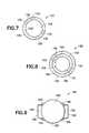
- FIG. 7is a cross-sectional view of a multi-lumen catheter, according to another embodiment of the invention.
- FIG. 8is a cross-sectional view of a multi-lumen catheter, according to yet another embodiment of the invention.
- FIG. 9is a cross-sectional view of a multi-lumen catheter, according to a still further embodiment of the invention.
- FIG. 10is a cross-sectional view of a multi-lumen catheter, according to another embodiment of the invention.
- FIG. 11is a cross-sectional view of a multi-lumen catheter, in another embodiment of the invention.
- FIG. 12is a cross-sectional view of a multi-lumen catheter, according to yet another embodiment of the invention.
- the present inventionrelates to multi-lumen lay-flat tubing, catheters comprising such tubing, methods for making such tubing, and articles including such multi-lumen lay-flat tubing catheters.
- the inventionrelates to a multi-lumen lay-flat tube formed of polymeric film material, comprising a main tube and at least one interior tubular passage, wherein each of the at least one interior tubular passage is constituted by reentrant portions of polymeric film material forming the main tube.
- the polymeric filmmay comprise a thermoplastic elastomeric material, such as a polyurethane film material, or a laminate including barrier film, tie layers, and exterior layers.
- a thermoplastic elastomeric materialsuch as a polyurethane film material, or a laminate including barrier film, tie layers, and exterior layers.
- the inventionin another aspect, relates to a balloon catheter, comprising: a multi-lumen lay-flat tube formed of polymeric film material, comprising a main tube and at least one interior tubular passage, wherein each of the at least one interior tubular passage is constituted by reentrant portions of polymeric film material forming the main tube; and an inflatable balloon secured to one end of the main tube, with one of said at least one interior tubular passage being in fluid communication with an interior volume of the inflatable balloon.
- the balloon cathetermay be configured so that the one tubular passage is joined in fluid communication to a fluid feed tube, whereby an inflation fluid can be flowed through said fluid feed tube and said one tubular passage to said balloon for inflation thereof.
- the balloon cathetercan further comprise a second interior tubular passage within said main tube, in which the second interior tubular passage terminating in an open end exterior of said balloon, whereby an irrigation fluid can be flowed through the second interior tubular passage to a local environment of said balloon.
- the inventionalso contemplates a method of forming a multi-lumen lay-flat tube, comprising: providing superposed sheets of polymeric film material; welding the superposed sheets of polymeric film material along generally parallel, spaced-apart seam lines to form at least two passages bounded by a successive pair of said seam lines; and everting the welded superposed sheets to form a main tube having at least one tubular passage therewithin.
- FIG. 1is a perspective view of an indwelling balloon catheter 10 , according to one embodiment of the present invention.
- the indwelling balloon catheter 10includes a main tubular body 12 , of elongated conformation, defining an interior lumen 14 in which is disposed a first tubular passage member 16 and a second tubular passage member 18 .
- the first tubular passage member 16has an opening 22 at the proximal end of the device, and the second tubular passage member 18 as an opening 20 at the proximal end of the device, as illustrated.
- the first tubular passage member 16has a gas feed tube 26 secured in fluid communication with the interior lumen of such member.
- the second tubular passage member 18has a fluid feed tube 24 secured in fluid communication with the interior lumen of the second tubular passage member.
- the main tubular body 12is secured to an inflatable balloon 28 .
- the first tubular passage member 16has a distal end opening 32 in communication with the interior volume of the balloon.
- the second tubular passage member 18has a distal end opening 34 that is open to the exterior environment of the balloon 28 .
- the gas feed tube 26can be coupled at its free proximal end with a source of pressurized gas, so that the pressurized gas flows through the gas feed tube 26 into the lumen of first tubular passage member 16 , and passes into the interior volume of the balloon 28 , for inflation thereof.
- the gas feed tube 26may be coupled to a pressure shutoff valve, or a check valve that will seal and maintain balloon 28 in an inflated state.
- the fluid feed tube 24may be coupled to a source of irrigation fluid, such as water or other liquid, so that the irrigation fluid flows through the fluid feed tube 24 into the lumen of the second tubular passage member 18 , and issues from the distal open end 34 of such second tubular passage member, to irrigate the local environment of the balloon 28 .
- a source of irrigation fluidsuch as water or other liquid
- the balloon catheterwhen positioned in the body of a human or other animal subject, with the balloon disposed in a body cavity or other physiological locus, is adapted to transmit irrigating fluid through fluid feed tube 24 , second tubular passage member 18 , and the open distal end 34 of such second tubular passage member, so that the physiological locus can be irrigated, and subsequently flow through the lumen of the main tubular body, for discharge at the proximal and thereof to a receptacle or other receiving means, such as a drain.
- a receptacle or other receiving meanssuch as a drain.
- FIG. 2is a cross-sectional view of the multi-lumen catheter of FIG. 1 , at the main tubular body 12 thereof.
- the main tubular body 12 as showndefines an interior lumen 14 , containing the first tubular passage member 16 defining lumen 22 therein and second tubular passage member 18 defining lumen 20 therein.
- the main tubular body 12has an inner surface 40 bounding the lumen 14 , and an exterior surface 42 .
- the inventionin one aspect contemplates a method of catheterizing a human subject, comprising use of a balloon catheter of the type shown in FIG. 1 , wherein the balloon is introduced into a body cavity of the human subject, and inflated by flow of gas through the interior tubular passage to the balloon.
- FIG. 3is a view of two superposed sheets 52 , 54 of polymeric material that have been welded at four seam lines 56 , 58 , 60 and 62 .
- a first sheet of polymeric material 52has edges 51 and 55 .
- a second sheet of polymeric edgeshas edges 53 and 57 .
- Edges 51 and 55are welded together by a first welded seam line 56 .
- Edges 53 and 57are welded together by a fourth welded seam line 62 .
- By such welded seam linesthere is formed a central tube 70 bounding central tubular passage 64 , first tubular passage member 72 bounding lumen 66 , and second tubular passage member 74 bounding lumen 68 . More specifically, as shown in FIG.
- the first tubular passage member 72is defined by the first welded seam line 56 , a second welded seam line 58 , a portion 61 of the first sheet of polymeric material 52 between the first welded seam line 56 and the second welded seam line 58 , and a portion 63 of the second sheet of polymeric material 54 between the first welded seam line 56 and the second welded seam line 58 .
- the central tubular passage 64is defined by the second welded seam line 58 , a third welded seam line 60 , a portion 65 of the first sheet of polymeric material 52 between the second welded seam line 58 and the third welded seam line 60 , and a portion 67 of the second sheet of polymeric material 54 between the second welded seam line 58 and the third welded seam line 60 .
- a second tubular passage member 74is defined by the third welded seam line 60 , the fourth welded seam line joining the edges 55 , 57 of the two sheets of polymeric material 52 , 54 , and portions of the two sheets of polymeric material 52 , 54 between the third welded seam line 60 and the fourth welded seam line 62 .
- the central tube 70is configured to be everted, as described with reference to FIG. 4 , so that the first tubular passage member 72 and the second tubular passage member are interiorly disposed within an additional lumen (not shown in FIG. 3 ) bounded by the everted central tube 70 .
- the two sheets of polymeric material 52 , 54are joined only by the plurality of generally parallel welded seam lines 56 , 58 , 60 , 62 joining edges of the two sheets of polymeric material 52 , 54 or dividing the welded-together sheets of polymeric material 52 , 54 into generally parallel tubular passage members.
- the sheets 52 , 54 of polymeric materialmay be of any suitable polymer construction, and may for example include polymeric materials such as polyethylene, polytetrafluoroethylene, polypropylene, polyurethane, polyvinylchloride, etc., with polyurethane in general being preferred.
- the twin sheets of polymeric material used in forming the multi-lumen tube of the inventionmay for example comprise a thermoplastic elastomer (TPE) material, and/or multilayer film, e.g., a laminate including barrier film, tie layers, and exterior layers.
- TPEthermoplastic elastomer
- multilayer filme.g., a laminate including barrier film, tie layers, and exterior layers.
- the two sheets that are welded to form the multi-lumen lay flat tube the inventionmay be the same as or different from one another.
- the thickness of the sheets 52 , 54 of polymeric materialmay be of any suitable dimension, and may for example have a thickness in a range of from about one mil up to 50 mils.
- the main tubular bodymay have any suitable inner and outer diameter dimensions. In various embodiments of the invention, the outer diameter is at least 0.25 inch, to accommodate the seam welding involved in the fabrication of the device.
- the seam welding of the filmsmay be carried out in any suitable manner, e.g., RF welding, impulse welding, ultrasonic welding, hotplate welding, hot wire welding, laser welding, etc. in general RF welding and laser welding are preferred techniques.
- the catheter article of the inventionis formed as a lay-flat catheter article, i.e., such article is reposeable on a flat surface to assume a flat conformation.
- FIG. 4is an elevational view of the welded sheet article of FIG. 3 , during the eversion process. All features and parts in FIG. 4 are numbered correspondingly with respect to the same features and parts in FIG. 3 .
- the lay-flat catheter articleis everted (turned inside-out) so that the first and second tubular members 72 and 74 , which were exterior to the central tube 70 in the as-formed state shown in FIG. 3 , are in the everted state interiorly disposed in the central tube 70 .
- FIG. 5is a view of two superposed sheets 80 , 82 of polymeric material that have been welded at six seam lines 100 , 102 , 104 , 106 , 108 and 110 , thereby forming central tube 84 having interior lumen 86 , first passage member 90 , second passage member 92 , third passage member 94 and fourth passage member 96 .
- FIG. 6is a cross-sectional view of a multi-lumen catheter formed by eversion of the welded sheet assembly of FIG. 5 . All reference numerals in FIG. 6 correspond to those shown in FIG. 5 . In the FIG. 6 catheter, four interior tubular passage members are provided.
- any number of interior passagescan be provided in the multi-lumen lay-flat catheter of the invention, as determined by the number of weld seam lines made at the margins of the superposed twin sheets of polymeric material. It will be apparent that the number of seam lines need not be the same at both sides of the superposed twin sheets, and that one side may for example provide two tubular passage members, while the other side may provide only one tubular passage member.
- the inventiontherefore provides a multi-lumen lay-flat tube article useful for catheter applications, and as a component of catheter structures such as the balloon catheter device illustratively shown in FIG. 1 hereof.
- the inventionin another aspect provides a method of making a multi-lumen lay-flat tubing article, involving providing concentric first and second tube members, and heat sealing the first and second to members to one another at circumferentially spaced-apart locations extending lengthwise along the tube members, to form a passage bounded by the circumferentially spaced-apart heat seals and interior facing wall portions of the tube members between such heat seals.
- a further aspect of the inventionrelates to a method of making a multi-lumen lay-flat tubing article, by providing concentric first and second tube members, and sealing the first and second to members to one another at circumferentially spaced-apart locations extending lengthwise along the tube members, to form a passage bounded by the circumferentially spaced-apart seals and interior facing wall portions of the tube members between such seals.
- Such methodmay further involve comprising the steps of providing a third tube member, and sealing the third tube member to the second tube member at circumferentially spaced-apart locations extending lengthwise along the second and third tube members, to thereby form at least one additional passage.
- the inventioncontemplates a method of making a multi-lumen lay-flat tube, comprising the steps of providing a first tube member, and adhesively bonding margins of an elongate strip to a surface of the first tube member, to form a longitudinally extending passage bounded by facing surfaces of the elongate strip and first tube member and adhesively bonded margins of the elongate strip.
- multi-lumen lay-flat articlescan be fabricated, e.g., a multi-lumen lay-flat tube, comprising concentric tube members, bonded to one another at longitudinally extending, circumferentially spaced-apart seals, to form at least one passage bounded by facing surfaces of the tube members and the circumferentially spaced-apart seals.
- a further aspect of the inventionrelates to a multi-lumen lay-flat tube, comprising a tube member having bonded thereto a strip member longitudinally extending along the tube member, with the strip member bonded at margins thereof to the tube member to form an enclosed passage between the strip member and tube member.
- the bondant used for such purposecan be of any suitable type, e.g., a medical grade UV-curable adhesive composition.
- FIG. 7is a cross-sectional view of a multi-lumen catheter 120 , according to another embodiment of the invention, constructed of concentric lay-flat tubing.
- the catheter 120includes an inner concentric wall 142 and an outer concentric wall 140 , defining an annular interior volume 130 therebetween.
- the inner concentric wall 142bounds a central bore opening 146 of the catheter.
- the annular interior volume 130contains circumferentially spaced-apart seals, e.g., heat seals 122 and 124 defining an enclosed arcuate annular passage 132 bounded by the inner concentric wall 142 , outer concentric wall 140 , and heat seals 122 and 124 .
- the seals instead of being heat sealsmay be adhesive seals, or other seal type.
- annular interior volume 130contains circumferentially spaced-apart seals, e.g., heat seals 126 and 128 , defining an enclosed arcuate annular passage 130 bounded by the inner concentric wall 142 , outer concentric wall 140 , and heat seals 126 and 128 .
- circumferentially spaced-apart sealse.g., heat seals 126 and 128 , defining an enclosed arcuate annular passage 130 bounded by the inner concentric wall 142 , outer concentric wall 140 , and heat seals 126 and 128 .
- arcuate annular passage 130may constitute an inflation passage for flow of an inflation gas to a balloon joined to one of the ends of the catheter
- arcuate annular passage 132may constitute an irrigation passage for flow of irrigating fluid along the catheter for delivery to an irrigation locus, e.g., a terminal opening delivering irrigation fluid into a body cavity, for irrigation of such cavity and efflux of the irrigation fluid from the body cavity through the central bore opening 146 of such catheter.
- FIG. 8is a cross-sectional view of a multi-lumen catheter 150 according to yet another embodiment of the invention.
- the catheter 150includes three concentric lay-flat tubing elements, inner tube 156 , intermediate tube 154 and outer tube 152 , defining respective annular volumes 158 and 160 , as illustrated.
- the catheterfeatures heat seals 168 and 164 between the inner and intermediate tubes, and heat seals 166 and 170 between the intermediate and outer tubes.
- This arrangementproduces a multi-lumen lay-flat catheter having a central bore opening 162 , two separated arcuate annular passages between the inner tube 156 and intermediate tube 154 , bounded by the heat seals 164 and 168 , and two separated arcuate annular passages between the intermediate tube 154 and outer tube 152 , bounded by the heat seals 166 and 170 .
- FIG. 9is a cross-sectional view of a multi-lumen catheter 180 , according to a still further embodiment of the invention.
- the catheter 180 in this embodimentfeatures a main lay-flat tube 182 , a first lay-flat exterior tube 184 enclosing interior volume 190 , a second lay-flat exterior tube 186 enclosing interior volume 192 , and heat seals 194 , 196 , 198 and 200 .
- the catheter 180 of FIG. 9can feature exterior tube passages, as illustrated, or the catheter article can be formed as shown in FIG. 9 and then everted, so that the formerly exterior tube passages become interior tube passages.
- FIG. 10is a cross-sectional view of a multi-lumen catheter 220 according to another embodiment of the invention.
- the catheter 220includes an inner concentric wall that is formed from two layers 228 and 230 of film that are bonded by heat seals 232 to one another to form the inner concentric wall.
- the outer concentric wallis likewise formed of two film material sheets 222 and 224 that are bonded together by heat seals 226 .
- each of the concentric inner and outer walls of the tubeis formed of two sheets or strips of thin film material such as polyurethane, which are bonded at their margins to one another, to constitute a tubular body.
- the inner and outer wallsalso are bonded to one another by heat seals 234 .
- heat seals 234adhesive seals or other seal types could be used.
- FIG. 11is a cross-sectional view of a multi-lumen catheter 250 according to yet another embodiment of the invention.
- the catheter 250includes three concentric tube elements, including an inner tube formed of two layers of film 264 and 268 , bonded to one another by seal 269 .
- An intermediate tubeis formed from two layers of thin film 258 and 260 , bonded to one another by seals 262 .
- the outer concentric tube of the assemblyis formed from respective sheets 252 and 254 of thin film material, bonded to one another by seals 256 .
- the inner, intermediate and outer tube elements of the assemblyare bonded by heat seals 270 as shown, to form respective lumens in each of the annular volumes between successive tube elements of the assembly.
- FIG. 12is a cross-sectional view of a multi-lumen catheter 280 according to a still further embodiment of the invention, having a conformation generally similar to that of FIG. 9 .
- the tube 182 in the catheter of FIG. 9is formed as a unitary main tube 182
- the main tube of catheter 280is formed from two layers 282 , 284 that are bonded to one another by seals 286 at their respective margins, so that the bonded sheets constitute the main tubular element shown in FIG. 12 .
Landscapes
- Health & Medical Sciences (AREA)
- Life Sciences & Earth Sciences (AREA)
- Heart & Thoracic Surgery (AREA)
- Engineering & Computer Science (AREA)
- Biophysics (AREA)
- Pulmonology (AREA)
- Anesthesiology (AREA)
- Biomedical Technology (AREA)
- Hematology (AREA)
- Animal Behavior & Ethology (AREA)
- General Health & Medical Sciences (AREA)
- Public Health (AREA)
- Veterinary Medicine (AREA)
- Child & Adolescent Psychology (AREA)
- Media Introduction/Drainage Providing Device (AREA)
Abstract
Description
- providing superposed sheets of polymeric film material;
- welding said superposed sheets of polymeric film material along generally parallel, spaced-apart seam lines to form at least two passages bounded by a successive pair of said seam lines; and
- everting said welded superposed sheets to form a main tube having at least one tubular passage therewithin.
Claims (14)
Priority Applications (1)
| Application Number | Priority Date | Filing Date | Title |
|---|---|---|---|
| US12/026,297US8585676B2 (en) | 2007-02-05 | 2008-02-05 | Multi-lumen lay-flat tubing, catheter articles comprising same, and method of manufacture thereof |
Applications Claiming Priority (2)
| Application Number | Priority Date | Filing Date | Title |
|---|---|---|---|
| US88829707P | 2007-02-05 | 2007-02-05 | |
| US12/026,297US8585676B2 (en) | 2007-02-05 | 2008-02-05 | Multi-lumen lay-flat tubing, catheter articles comprising same, and method of manufacture thereof |
Publications (2)
| Publication Number | Publication Date |
|---|---|
| US20080188802A1 US20080188802A1 (en) | 2008-08-07 |
| US8585676B2true US8585676B2 (en) | 2013-11-19 |
Family
ID=39676795
Family Applications (1)
| Application Number | Title | Priority Date | Filing Date |
|---|---|---|---|
| US12/026,297Active2029-05-11US8585676B2 (en) | 2007-02-05 | 2008-02-05 | Multi-lumen lay-flat tubing, catheter articles comprising same, and method of manufacture thereof |
Country Status (1)
| Country | Link |
|---|---|
| US (1) | US8585676B2 (en) |
Cited By (10)
| Publication number | Priority date | Publication date | Assignee | Title |
|---|---|---|---|---|
| WO2018031883A1 (en)* | 2016-08-12 | 2018-02-15 | Cognition Medical Corp | Permeable structural interface for the construction of thin-walled balloon catheters |
| US10182932B2 (en) | 2012-02-21 | 2019-01-22 | Allurion Technologies, Inc. | Methods and devices for deploying and releasing a temporary implant within the body |
| US10307279B2 (en) | 2012-02-21 | 2019-06-04 | Allurion Technologies, Inc. | Ingestible delivery systems and methods |
| US10786379B2 (en) | 2012-02-21 | 2020-09-29 | Allurion Technologies, Inc. | Methods and devices for deploying and releasing a temporary implant within the body |
| US11083613B2 (en) | 2017-01-23 | 2021-08-10 | Baronova, Inc. | Gastric obstruction device deployment assembly and methods of delivering and deploying a gastric obstruction device |
| US11098813B2 (en) | 2018-07-06 | 2021-08-24 | Allurion Technologies, Inc. | Binary fluid control valve system |
| US11497900B2 (en) | 2018-12-13 | 2022-11-15 | Allurion Technologies, Inc. | Enhanced fluid delivery system |
| US11559418B2 (en) | 2018-02-26 | 2023-01-24 | Allurion Technologies, Inc. | Automatic-sealing balloon-filling catheter system |
| US12245962B2 (en) | 2023-04-12 | 2025-03-11 | Allurion Technologies, Inc. | Balloon sealing and fill valve |
| US12246163B2 (en) | 2023-04-12 | 2025-03-11 | Allurion Technologies, Inc. | Automatic-sealing balloon-filling catheter system |
Families Citing this family (17)
| Publication number | Priority date | Publication date | Assignee | Title |
|---|---|---|---|---|
| US20040127932A1 (en)* | 2002-09-12 | 2004-07-01 | Shah Tilak M. | Dip-molded polymeric medical devices with reverse thickness gradient, and method of making same |
| US20080172080A1 (en)* | 2007-01-16 | 2008-07-17 | Isham John | Minimally invasive rectal balloon apparatus |
| US9707379B2 (en) | 2007-01-16 | 2017-07-18 | Radiadyne Llc | Rectal balloon with locking stopper |
| US9381334B2 (en) | 2007-01-16 | 2016-07-05 | Radiadyne Llc | Endorectal balloon with gas release lumen |
| US8500771B2 (en) | 2007-01-16 | 2013-08-06 | Radiadyne, Llc | Rectal balloon apparatus with pressure relieving lumen and sensors |
| US8105299B2 (en)* | 2007-04-23 | 2012-01-31 | Polyzen Inc. | Extrusion blow-molded corporeal port mounting structure |
| US8167859B2 (en)* | 2007-04-23 | 2012-05-01 | Polyzen Inc. | Ostomy bag mounting structure |
| JP5474779B2 (en)* | 2007-06-12 | 2014-04-16 | コンバテック・テクノロジーズ・インコーポレイテッド | Ostomy device |
| US7976497B2 (en)* | 2007-09-25 | 2011-07-12 | Polyzen Inc. | Multi-layer film welded articulated balloon |
| WO2009135141A1 (en) | 2008-05-01 | 2009-11-05 | Bristol-Myers Squibb Company | Rectal drain appliance |
| DE102008042718A1 (en)* | 2008-10-09 | 2010-04-15 | Invendo Medical Gmbh | Medical engineering, elastic polymer tube and method for its production |
| US8585950B2 (en) | 2009-01-29 | 2013-11-19 | Angiodynamics, Inc. | Multilumen catheters and method of manufacturing |
| US20100274189A1 (en)* | 2009-04-22 | 2010-10-28 | Pressure Products Medical Supplies Inc. | Balloon catheter and method of manufacture of the same |
| US8597012B2 (en) | 2010-05-11 | 2013-12-03 | Polyzen, Inc. | Air disengagement assembly and method for manufacturing dip-molded articles out of RTV silicone by fully automated process |
| US8177742B1 (en) | 2010-12-23 | 2012-05-15 | Kimberly-Clark Wordwide, Inc. | Inflatable retention system for an enteral feeding device |
| WO2015088793A2 (en)* | 2013-12-12 | 2015-06-18 | Mirizzi Michael S | Multiple chamber, expandable therapeutic agent delivery device |
| US11617855B2 (en) | 2018-07-13 | 2023-04-04 | Harjeet Brar | Self-washing catheter |
Citations (37)
| Publication number | Priority date | Publication date | Assignee | Title |
|---|---|---|---|---|
| US4043345A (en)* | 1974-05-02 | 1977-08-23 | Byk Gulden Lomberg Chemische Fabrik Gmbh | Catheter |
| US4311146A (en) | 1980-05-08 | 1982-01-19 | Sorenson Research Co., Inc. | Detachable balloon catheter apparatus and method |
| US4464175A (en) | 1982-08-25 | 1984-08-07 | Altman Alan R | Multipurpose tamponade and thrombosclerotherapy tube |
| US4650463A (en)* | 1984-12-24 | 1987-03-17 | Leveen Harry H | Perforated tubing |
| US4784133A (en)* | 1987-01-28 | 1988-11-15 | Mackin Robert A | Working well balloon angioscope and method |
| US5116310A (en)* | 1990-07-30 | 1992-05-26 | Helix Medical, Inc. | Multiple lumen wound drain with bypass openings |
| US5219792A (en)* | 1991-01-14 | 1993-06-15 | Samsung Electronics Co., Ltd. | Method for forming multilevel interconnection in a semiconductor device |
| US5234454A (en) | 1991-08-05 | 1993-08-10 | Akron City Hospital | Percutaneous intragastric balloon catheter and method for controlling body weight therewith |
| US5360414A (en)* | 1992-10-08 | 1994-11-01 | Yarger Richard J | Tube for draining body cavities, viscera and wounds |
| US5433252A (en)* | 1992-02-27 | 1995-07-18 | Woco Franz-Josef Wolf & Co. | Fluid containing coaxial tube for control systems |
| US5527280A (en) | 1995-03-29 | 1996-06-18 | The Children's Seashore House | Multi-lumen enteral feeding and medicating device |
| US5679423A (en) | 1993-08-11 | 1997-10-21 | Polygenex International, Inc. | Polyurethane elastomer organ bag of welded polyurethane film |
| US5807333A (en) | 1995-09-21 | 1998-09-15 | Abbott Laboratories | Peristaltic pump and fluid delivery set |
| US5879499A (en)* | 1996-06-17 | 1999-03-09 | Heartport, Inc. | Method of manufacture of a multi-lumen catheter |
| US5924456A (en)* | 1993-07-01 | 1999-07-20 | Hutchinson | Tubular section member, in particular for use as a fluid flow duct |
| US5951514A (en)* | 1997-03-07 | 1999-09-14 | Sahota; Harvinder | Multi-lobe perfusion balloon |
| US5996639A (en)* | 1997-01-30 | 1999-12-07 | Action Technology | Multiple compartment corrugated hose |
| US6022313A (en)* | 1996-03-19 | 2000-02-08 | Cardiothoracic Systems, Inc. | Method and apparatus for the minimally invasive harvesting of a saphenous vein and the like |
| US6249708B1 (en)* | 1997-08-26 | 2001-06-19 | Angeion Corporation | Fluted channel construction for a multi-conductor catheter lead |
| US6270477B1 (en) | 1996-05-20 | 2001-08-07 | Percusurge, Inc. | Catheter for emboli containment |
| US6291543B1 (en) | 2000-05-24 | 2001-09-18 | Polyzen, Inc. | Surfacially cross-linked elastoplastic articles, and method of making the same |
| US6352077B1 (en) | 2000-05-01 | 2002-03-05 | Tilak M. Shah | Film welded reservoir bag for breathing circuit and method of making the same |
| US6460541B1 (en) | 2000-11-07 | 2002-10-08 | Polyzen, Inc. | Heat-sealed inflatable article, and method of making the same |
| US6478789B1 (en)* | 1999-11-15 | 2002-11-12 | Allegiance Corporation | Wound drain with portals to enable uniform suction |
| US20030088209A1 (en)* | 2000-02-16 | 2003-05-08 | Jessica Chiu | Multi-lumen extrusion tubing |
| US6592544B1 (en)* | 1999-11-24 | 2003-07-15 | Edwards Lifesciences Corporation | Vascular access devices having hemostatic safety valve |
| US6663646B1 (en) | 2000-10-24 | 2003-12-16 | Tilak M. Shah | Isotropically expansible balloon articles useful in in vivo lumenal procedures, and method of making such balloon articles |
| US6712832B2 (en) | 2001-10-15 | 2004-03-30 | Tilak M. Shah | Low-pressure medical balloons and method of making same |
| US6805662B2 (en) | 2003-02-18 | 2004-10-19 | Polyzen, Inc. | Urinary incontinence control device and method of use |
| US6827710B1 (en)* | 1996-11-26 | 2004-12-07 | Edwards Lifesciences Corporation | Multiple lumen access device |
| US6875193B1 (en)* | 1998-02-06 | 2005-04-05 | Possis Medical, Inc. | Rapid exchange fluid jet thrombectomy device and method |
| US20050222329A1 (en) | 2004-04-01 | 2005-10-06 | Shah Tilak M | Extrusion laminate polymeric film article and gastric occlusive device comprising same |
| US6960199B2 (en) | 2000-12-14 | 2005-11-01 | J&R Medical Devices, Inc. | Method for feeding with a tube |
| US20060129094A1 (en) | 2004-05-26 | 2006-06-15 | Shah Tilak M | Gastro-occlusive device |
| US20060212064A1 (en) | 2002-09-12 | 2006-09-21 | Shah Tilak M | Dip-molded polymeric medical devices with reverse thickness gradient, and methood of making same |
| US7220252B2 (en) | 2003-07-18 | 2007-05-22 | Polyzen, Inc. | Inflatable dual balloon catheter |
| US20090082724A1 (en) | 2007-09-25 | 2009-03-26 | Polyzen Inc. | Multi-layer film welded articulated balloon |
- 2008
- 2008-02-05USUS12/026,297patent/US8585676B2/enactiveActive
Patent Citations (42)
| Publication number | Priority date | Publication date | Assignee | Title |
|---|---|---|---|---|
| US4043345A (en)* | 1974-05-02 | 1977-08-23 | Byk Gulden Lomberg Chemische Fabrik Gmbh | Catheter |
| US4311146A (en) | 1980-05-08 | 1982-01-19 | Sorenson Research Co., Inc. | Detachable balloon catheter apparatus and method |
| US4464175A (en) | 1982-08-25 | 1984-08-07 | Altman Alan R | Multipurpose tamponade and thrombosclerotherapy tube |
| US4650463A (en)* | 1984-12-24 | 1987-03-17 | Leveen Harry H | Perforated tubing |
| US4784133A (en)* | 1987-01-28 | 1988-11-15 | Mackin Robert A | Working well balloon angioscope and method |
| US5116310A (en)* | 1990-07-30 | 1992-05-26 | Helix Medical, Inc. | Multiple lumen wound drain with bypass openings |
| US5219792A (en)* | 1991-01-14 | 1993-06-15 | Samsung Electronics Co., Ltd. | Method for forming multilevel interconnection in a semiconductor device |
| US5234454A (en) | 1991-08-05 | 1993-08-10 | Akron City Hospital | Percutaneous intragastric balloon catheter and method for controlling body weight therewith |
| US5433252A (en)* | 1992-02-27 | 1995-07-18 | Woco Franz-Josef Wolf & Co. | Fluid containing coaxial tube for control systems |
| US5360414A (en)* | 1992-10-08 | 1994-11-01 | Yarger Richard J | Tube for draining body cavities, viscera and wounds |
| US5924456A (en)* | 1993-07-01 | 1999-07-20 | Hutchinson | Tubular section member, in particular for use as a fluid flow duct |
| US5679423A (en) | 1993-08-11 | 1997-10-21 | Polygenex International, Inc. | Polyurethane elastomer organ bag of welded polyurethane film |
| US5833915A (en) | 1993-08-11 | 1998-11-10 | Polygenex International, Inc. | Method of welding polyurethane thin film |
| US5527280A (en) | 1995-03-29 | 1996-06-18 | The Children's Seashore House | Multi-lumen enteral feeding and medicating device |
| US5807333A (en) | 1995-09-21 | 1998-09-15 | Abbott Laboratories | Peristaltic pump and fluid delivery set |
| US6022313A (en)* | 1996-03-19 | 2000-02-08 | Cardiothoracic Systems, Inc. | Method and apparatus for the minimally invasive harvesting of a saphenous vein and the like |
| US6270477B1 (en) | 1996-05-20 | 2001-08-07 | Percusurge, Inc. | Catheter for emboli containment |
| US5879499A (en)* | 1996-06-17 | 1999-03-09 | Heartport, Inc. | Method of manufacture of a multi-lumen catheter |
| US6827710B1 (en)* | 1996-11-26 | 2004-12-07 | Edwards Lifesciences Corporation | Multiple lumen access device |
| US5996639A (en)* | 1997-01-30 | 1999-12-07 | Action Technology | Multiple compartment corrugated hose |
| US5951514A (en)* | 1997-03-07 | 1999-09-14 | Sahota; Harvinder | Multi-lobe perfusion balloon |
| US6249708B1 (en)* | 1997-08-26 | 2001-06-19 | Angeion Corporation | Fluted channel construction for a multi-conductor catheter lead |
| US6875193B1 (en)* | 1998-02-06 | 2005-04-05 | Possis Medical, Inc. | Rapid exchange fluid jet thrombectomy device and method |
| US6478789B1 (en)* | 1999-11-15 | 2002-11-12 | Allegiance Corporation | Wound drain with portals to enable uniform suction |
| US6592544B1 (en)* | 1999-11-24 | 2003-07-15 | Edwards Lifesciences Corporation | Vascular access devices having hemostatic safety valve |
| US20030088209A1 (en)* | 2000-02-16 | 2003-05-08 | Jessica Chiu | Multi-lumen extrusion tubing |
| US6352077B1 (en) | 2000-05-01 | 2002-03-05 | Tilak M. Shah | Film welded reservoir bag for breathing circuit and method of making the same |
| US6291543B1 (en) | 2000-05-24 | 2001-09-18 | Polyzen, Inc. | Surfacially cross-linked elastoplastic articles, and method of making the same |
| US6663646B1 (en) | 2000-10-24 | 2003-12-16 | Tilak M. Shah | Isotropically expansible balloon articles useful in in vivo lumenal procedures, and method of making such balloon articles |
| US6460541B1 (en) | 2000-11-07 | 2002-10-08 | Polyzen, Inc. | Heat-sealed inflatable article, and method of making the same |
| US6960199B2 (en) | 2000-12-14 | 2005-11-01 | J&R Medical Devices, Inc. | Method for feeding with a tube |
| US6712832B2 (en) | 2001-10-15 | 2004-03-30 | Tilak M. Shah | Low-pressure medical balloons and method of making same |
| US20060212064A1 (en) | 2002-09-12 | 2006-09-21 | Shah Tilak M | Dip-molded polymeric medical devices with reverse thickness gradient, and methood of making same |
| US6805662B2 (en) | 2003-02-18 | 2004-10-19 | Polyzen, Inc. | Urinary incontinence control device and method of use |
| US7220252B2 (en) | 2003-07-18 | 2007-05-22 | Polyzen, Inc. | Inflatable dual balloon catheter |
| US20070239110A1 (en) | 2003-07-18 | 2007-10-11 | Shah Tilak M | Treatment methods utilizing inflatable dual balloon catheter |
| US20050222329A1 (en) | 2004-04-01 | 2005-10-06 | Shah Tilak M | Extrusion laminate polymeric film article and gastric occlusive device comprising same |
| US20070212559A1 (en) | 2004-04-01 | 2007-09-13 | Shah Tilak M | Gastric occlusive device fabrication |
| US20070299463A1 (en) | 2004-04-01 | 2007-12-27 | Shah Tilak M | Therapeutic intervention systems employing implantable balloon devices |
| US20060129094A1 (en) | 2004-05-26 | 2006-06-15 | Shah Tilak M | Gastro-occlusive device |
| US7112186B2 (en) | 2004-05-26 | 2006-09-26 | Shah Tilak M | Gastro-occlusive device |
| US20090082724A1 (en) | 2007-09-25 | 2009-03-26 | Polyzen Inc. | Multi-layer film welded articulated balloon |
Non-Patent Citations (2)
| Title |
|---|
| Co-Pending U.S. Appl. No. 12/106,743, entitled "Ostomy Bag Mounting Structure", filed Apr. 21, 2008 in the name of Tilak Shah. |
| Co-Pending U.S. Appl. No. 12/106,760, entitled, "Extrusion Blow-Molded Corporeal Port Mounting Structure", filed Apr. 21, 2008 in the name of Tilak Shah. |
Cited By (16)
| Publication number | Priority date | Publication date | Assignee | Title |
|---|---|---|---|---|
| US10182932B2 (en) | 2012-02-21 | 2019-01-22 | Allurion Technologies, Inc. | Methods and devices for deploying and releasing a temporary implant within the body |
| US10307279B2 (en) | 2012-02-21 | 2019-06-04 | Allurion Technologies, Inc. | Ingestible delivery systems and methods |
| US10729572B2 (en) | 2012-02-21 | 2020-08-04 | Allurion Technologies, Inc. | Methods and devices for deploying and releasing a temporary implant within the body |
| US10786379B2 (en) | 2012-02-21 | 2020-09-29 | Allurion Technologies, Inc. | Methods and devices for deploying and releasing a temporary implant within the body |
| US12409056B2 (en) | 2012-02-21 | 2025-09-09 | Allurion Technologies, Llc | Methods and devices for deploying and releasing a temporary implant within the body |
| US11766346B2 (en) | 2012-02-21 | 2023-09-26 | Allurion Technologies, Inc. | Methods and devices for deploying and releasing a temporary implant within the body |
| WO2018031883A1 (en)* | 2016-08-12 | 2018-02-15 | Cognition Medical Corp | Permeable structural interface for the construction of thin-walled balloon catheters |
| US11083613B2 (en) | 2017-01-23 | 2021-08-10 | Baronova, Inc. | Gastric obstruction device deployment assembly and methods of delivering and deploying a gastric obstruction device |
| US11559418B2 (en) | 2018-02-26 | 2023-01-24 | Allurion Technologies, Inc. | Automatic-sealing balloon-filling catheter system |
| US12109138B2 (en) | 2018-02-26 | 2024-10-08 | Allurion Technologies, Inc. | Automatic-sealing balloon-filling catheter system |
| US11828377B2 (en) | 2018-07-06 | 2023-11-28 | Allurion Technologies, Inc. | Binary fluid control valve system |
| US12209677B2 (en) | 2018-07-06 | 2025-01-28 | Allurion Technologies, Inc. | Binary fluid control valve system |
| US11098813B2 (en) | 2018-07-06 | 2021-08-24 | Allurion Technologies, Inc. | Binary fluid control valve system |
| US11497900B2 (en) | 2018-12-13 | 2022-11-15 | Allurion Technologies, Inc. | Enhanced fluid delivery system |
| US12245962B2 (en) | 2023-04-12 | 2025-03-11 | Allurion Technologies, Inc. | Balloon sealing and fill valve |
| US12246163B2 (en) | 2023-04-12 | 2025-03-11 | Allurion Technologies, Inc. | Automatic-sealing balloon-filling catheter system |
Also Published As
| Publication number | Publication date |
|---|---|
| US20080188802A1 (en) | 2008-08-07 |
Similar Documents
| Publication | Publication Date | Title |
|---|---|---|
| US8585676B2 (en) | Multi-lumen lay-flat tubing, catheter articles comprising same, and method of manufacture thereof | |
| US8167859B2 (en) | Ostomy bag mounting structure | |
| US7976497B2 (en) | Multi-layer film welded articulated balloon | |
| US7553387B2 (en) | Catheters with lubricious linings and methods for making and using them | |
| US9629978B2 (en) | Catheters with intermediate layers and methods for making them | |
| CN101421000B (en) | Breakable or removable valves and instruments | |
| AU683574B2 (en) | Non-coextrusion method of making multi-layer angioplasty balloons | |
| JP3418872B2 (en) | Medical catheter and method of manufacturing the same | |
| US5270086A (en) | Multilayer extrusion of angioplasty balloons | |
| US5337734A (en) | Disposable sheath with optically transparent window formed continuously integral therewith | |
| US20070075452A1 (en) | Catheters with lubricious linings and methods for making and using them | |
| CN103764217B (en) | through tip of catheter | |
| US20110245806A1 (en) | Reinforced multi-lumen catheter and methods for making same | |
| US20080282609A1 (en) | Irrigation sheets | |
| US11471647B2 (en) | Connection system for tunneled catheters | |
| US7588715B2 (en) | Balloon forming method and balloon | |
| JP2015181886A (en) | Medical tube, balloon catheter and method of manufacturing medical tube | |
| JP2004532059A5 (en) | ||
| CN112093253B (en) | Storage bag | |
| US20250320935A1 (en) | A tube | |
| WO1997041820A1 (en) | Dispenser unit, process for manufacturing the same and its use | |
| IT201800007425A1 (en) | SEMI-RIGID DUCT FOR THE CONVEYANCE OF A GAS AND METHOD OF PRODUCTION OF SAID DUCT | |
| EP4531769A1 (en) | A tube | |
| US20170135904A1 (en) | Filling Needle for Use in a Tube Layer for Transferring a Flowable Medium, in Particular a Pharmaceutical Product | |
| JPH10216225A (en) | Peritoneal dialysis kit |
Legal Events
| Date | Code | Title | Description |
|---|---|---|---|
| STCF | Information on status: patent grant | Free format text:PATENTED CASE | |
| FPAY | Fee payment | Year of fee payment:4 | |
| MAFP | Maintenance fee payment | Free format text:PAYMENT OF MAINTENANCE FEE, 8TH YR, SMALL ENTITY (ORIGINAL EVENT CODE: M2552); ENTITY STATUS OF PATENT OWNER: SMALL ENTITY Year of fee payment:8 | |
| AS | Assignment | Owner name:POLYZEN INC., NORTH CAROLINA Free format text:ASSIGNMENT OF ASSIGNORS INTEREST;ASSIGNOR:SHAH, TILAK M.;REEL/FRAME:061346/0290 Effective date:20221007 | |
| AS | Assignment | Owner name:POLYZEN, LLC, DELAWARE Free format text:CHANGE OF NAME;ASSIGNOR:POLYZEN, INC.;REEL/FRAME:062170/0361 Effective date:20221101 | |
| AS | Assignment | Owner name:JPMORGAN CHASE BANK, N.A., AS ADMINISTRATIVE AGENT, ILLINOIS Free format text:SECURITY INTEREST;ASSIGNOR:POLYZEN, LLC;REEL/FRAME:062196/0508 Effective date:20221223 | |
| FEPP | Fee payment procedure | Free format text:ENTITY STATUS SET TO UNDISCOUNTED (ORIGINAL EVENT CODE: BIG.); ENTITY STATUS OF PATENT OWNER: LARGE ENTITY | |
| MAFP | Maintenance fee payment | Free format text:PAYMENT OF MAINTENANCE FEE, 12TH YR, SMALL ENTITY (ORIGINAL EVENT CODE: M2553); ENTITY STATUS OF PATENT OWNER: SMALL ENTITY Year of fee payment:12 Free format text:PAYMENT OF MAINTENANCE FEE UNDER 1.28(C) (ORIGINAL EVENT CODE: M1559); ENTITY STATUS OF PATENT OWNER: LARGE ENTITY |