US8584770B2 - Spindle bearing arrangement for a power tool - Google Patents
Spindle bearing arrangement for a power toolDownload PDFInfo
- Publication number
- US8584770B2 US8584770B2US12/729,867US72986710AUS8584770B2US 8584770 B2US8584770 B2US 8584770B2US 72986710 AUS72986710 AUS 72986710AUS 8584770 B2US8584770 B2US 8584770B2
- Authority
- US
- United States
- Prior art keywords
- transmission
- spindle
- output
- power tool
- housing
- Prior art date
- Legal status (The legal status is an assumption and is not a legal conclusion. Google has not performed a legal analysis and makes no representation as to the accuracy of the status listed.)
- Active, expires
Links
Images


Classifications
- B—PERFORMING OPERATIONS; TRANSPORTING
- B25—HAND TOOLS; PORTABLE POWER-DRIVEN TOOLS; MANIPULATORS
- B25F—COMBINATION OR MULTI-PURPOSE TOOLS NOT OTHERWISE PROVIDED FOR; DETAILS OR COMPONENTS OF PORTABLE POWER-DRIVEN TOOLS NOT PARTICULARLY RELATED TO THE OPERATIONS PERFORMED AND NOT OTHERWISE PROVIDED FOR
- B25F5/00—Details or components of portable power-driven tools not particularly related to the operations performed and not otherwise provided for
- B25F5/001—Gearings, speed selectors, clutches or the like specially adapted for rotary tools
- B—PERFORMING OPERATIONS; TRANSPORTING
- B23—MACHINE TOOLS; METAL-WORKING NOT OTHERWISE PROVIDED FOR
- B23Q—DETAILS, COMPONENTS, OR ACCESSORIES FOR MACHINE TOOLS, e.g. ARRANGEMENTS FOR COPYING OR CONTROLLING; MACHINE TOOLS IN GENERAL CHARACTERISED BY THE CONSTRUCTION OF PARTICULAR DETAILS OR COMPONENTS; COMBINATIONS OR ASSOCIATIONS OF METAL-WORKING MACHINES, NOT DIRECTED TO A PARTICULAR RESULT
- B23Q5/00—Driving or feeding mechanisms; Control arrangements therefor
- B23Q5/02—Driving main working members
- B23Q5/04—Driving main working members rotary shafts, e.g. working-spindles
- B—PERFORMING OPERATIONS; TRANSPORTING
- B25—HAND TOOLS; PORTABLE POWER-DRIVEN TOOLS; MANIPULATORS
- B25B—TOOLS OR BENCH DEVICES NOT OTHERWISE PROVIDED FOR, FOR FASTENING, CONNECTING, DISENGAGING OR HOLDING
- B25B21/00—Portable power-driven screw or nut setting or loosening tools; Attachments for drilling apparatus serving the same purpose
- B25B21/02—Portable power-driven screw or nut setting or loosening tools; Attachments for drilling apparatus serving the same purpose with means for imparting impact to screwdriver blade or nut socket
Definitions
- the present disclosurerelates to a spindle bearing arrangement for a power tool.
- U.S. Pat. No. 6,431,289 and U.S. patent application Ser. No. 12/610,762disclose various rotary power tools having an output spindle, which is driven by a planetary-type transmission, and a torque limiting clutch for selectively limiting an output torque of the rotary power tool. While such rotary power tools are satisfactory for their intended purposes, such rotary power tools are nonetheless susceptible to improvement.
- the teachings of the present disclosureprovide a power tool having a motor, a housing, a transmission, an output spindle, a first bearing and a second bearing.
- the motorhas an output shaft.
- the transmissionis at least partly disposed in the housing and receives a rotary input from the output shaft.
- the transmissionincludes a planet carrier.
- the output spindleis driven by the transmission and includes a first end, which is supported for rotation about a spindle axis by the planet carrier, and a second end opposite the first end.
- the first bearingis disposed between the housing and the planet carrier and supports the planet carrier for rotation about the spindle axis.
- the second bearingis disposed between the housing and the output spindle and is configured to support the output spindle for rotation about the spindle axis at a location proximate the second end.
- the teachings of the present disclosureprovide a power tool with a motor, a housing, a transmission, an output spindle, a front bearing and a rear bearing.
- the motorhas an output shaft.
- the transmissionis disposed in the housing and receives a rotary input from the output shaft.
- the transmissionincludes an input planetary stage, which has an input planet carrier, and an output planetary stage.
- the output spindleis driven by the transmission and has a first end, which extends at least partly through the input planetary stage, and a second end opposite the first end.
- the front bearingis disposed between the output spindle and the housing to support the second end of the output spindle for rotation about the spindle axis.
- the rear bearingindirectly supports the first end of the output spindle in the housing for rotation about the spindle axis.
- the present disclosureprovides a power tool that includes a motor, a housing, a transmission, an output spindle, a spindle lock and front and rear bearings.
- the motorhas an output shaft.
- the transmissionis disposed in the housing and receives a rotary input from the output shaft.
- the transmissionincludes an input planetary stage, which has an input planet carrier, and an output planetary stage.
- the output spindleis driven by the transmission and is received through the output planetary stage such that the first end extends at least partly through the input planetary stage.
- the spindle lockis mounted on the output spindle between the first and second ends.
- the front and rear bearingswhich are disposed on opposite sides of the spindle lock, support the output spindle relative to the housing for rotation about a spindle axis.
- FIG. 1is a side elevation view of an exemplary tool constructed in accordance with the teachings of the present disclosure
- FIG. 2is an exploded perspective view of the tool of FIG. 1 ;
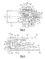
- FIG. 3is a longitudinal section view of a portion of the tool of FIG. 1 ;
- FIGS. 4 through 6are section views of portions of five other tools constructed in accordance with the teachings of the present disclosure.
- a power tool constructed in accordance with the teachings of the present disclosureis generally indicated by reference numeral 10 .
- the power tool 10may be either a corded (e.g., AC powered) or cordless (e.g., DC battery operated) device, such as a portable screwdriver, impact driver, drill/driver or hammer drill/drill.
- the power tool 10is a cordless screwdriver having a housing 12 , a motor assembly 14 , a transmission assembly 16 , an output spindle 18 , a spindle lock 20 , a clutch mechanism 22 , a chuck 24 , a trigger assembly 26 and a battery pack 28 .
- the housing 12can include a pair of clam shell housing halves 40 only one shown in FIG. 2 ) that can cooperate to define a body 42 , a handle 44 and a battery interface 46 that can be configured to receive the battery pack 28 .
- the handle 44can house the trigger assembly 26 in a conventional manner, while the body 42 can define a motor cavity 48 into which the motor assembly 14 can be received.
- the housing 12can be configured with an exterior gear case housing (not shown) that can be coupled to a front side of the body 42 and configured to shroud or cover all or portions of the transmission assembly 16 and clutch mechanism 22 .
- the clam shell housing halves 40are configured to shroud or cover the transmission assembly 16 and the clutch mechanism 22 .
- the motor assembly 14can comprise a motor 60 and an adapter plate 62 .
- the motor 60can be any type of motor, such as a DC electric motor, and can include an output shaft 64 .
- the motor 60can be received in the motor cavity 48 and can be electrically coupled to the trigger assembly 26 and the battery pack 28 .
- the adapter plate 62can be fixedly coupled to an end of the motor 60 .
- the transmission assembly 16can comprise a transmission housing 80 and a transmission 82 .
- the transmission housing 80can be a hollow, generally tubular structure that is configured to house the transmission 82 and portions of the clutch mechanism 22 .
- the transmission housing 80can be received into the motor cavity 48 and can engage the clam shell housing halves 40 such that the transmission housing 80 is axially fixed and non-rotatably engaged to the housing 12 .
- the transmission housing 80can define a front bearing mount 90 and a central cavity 92 having a first shoulder 94 , a second shoulder 96 and a third shoulder 98 .
- the transmission 82can be a planetary-type transmission having an input planetary stage 110 and an output planetary stage 112 that can be received in the central cavity 92 of the transmission housing 80 .
- the particular transmission depicted and described hereinis a two-stage, single speed transmission, the teachings of the present disclosure have application to other types of transmissions, including those that are operable in more than one speed ratio and/or those that comprise fewer or more than two planetary stages (i.e., a single stage planetary transmission or a transmission having at least one planetary stage disposed between the input and output planetary stages 110 and 112 ).
- the input planetary stage 110can comprise an input sun gear 120 , a plurality of input planet gears 122 , an input planet carrier 124 and an input ring gear 126
- the output planetary stage 112can comprise an output sun gear 130 , a plurality of output planet gears 132 , an output planet carrier 134 and an output ring gear 136 .
- the input sun gear 120can be mounted on the output shaft 64 of the motor 60 for rotation therewith.
- the input planet gears 122can be meshingly engaged with the input sun gear 120 and the input ring gear 126 .
- the input planet carrier 124can comprise a carrier body 140 and a plurality of pins 142 that can be mounted to the carrier body 140 .
- Each of the input planet gears 122can be rotatably mounted on a respective one of the pins 142 .
- the input ring gear 126can be abutted against the first shoulder 94 .
- the adapter plate 62can be received in the central cavity 92 and non-rotatably coupled to the transmission housing 80 to thereby limit rearward axial movement of the input ring gear 126 relative to the transmission housing 80 , as well as to inhibit rotation of the motor 60 relative to the transmission housing 80 .
- the output sun gear 130can be coupled to the carrier body 140 of the input planet carrier 124 for rotation therewith.
- the output planet gears 132can be meshingly engaged with the output sun gear 130 and the output ring gear 136 .
- the output planet carrier 134can comprise a carrier body 150 and a plurality of pins 152 that can be mounted to the carrier body 150 .
- Each of the output planet gears 132can be rotatably mounted on a respective one of the pins 152 of the output carrier 134 .
- the output ring gear 136can be abutted against the second shoulder 96 and non-rotatably engaged to the transmission housing 80 .
- the output ring gear 136includes a plurality of external teeth 160 that are engaged to internal teeth 162 formed on the interior of the transmission housing 80 proximate the second shoulder 96 .
- the output spindle 18can be a unitarily formed shaft structure that can be received at least partially through the transmission 82 .
- the output spindle 18can comprise a rear end 170 , a front end 172 and an anvil mount 174 that can be disposed between the rear and front ends 170 and 172 .
- the rear end 170can be generally cylindrically shaped and can extend fully or partly through the input planetary stage 110 where it can be supported for rotation by an element of the transmission 82 .
- the rear end 170can extend through or into at least one of the output sun gear 130 and the carrier body 140 of the input planet carrier 124 such that the input planet carrier 124 supports the rear end 170 of the output spindle 18 .
- the output shaft 64 of the motor 60can be received in an appropriately sized aperture 180 in the rear end 170 of the output spindle 18 .
- a suitable rear bearing 190such as a journal bearing or bushing, can be disposed between the transmission housing 80 and the carrier body 140 of the input planet carrier 124 to support the input planet carrier 124 for rotation about a spindle axis 200 . It will be appreciated that the rear bearing 190 , which can be disposed axially between the input ring gear 126 and the output ring gear 136 , can indirectly support the rear end 170 of the output spindle 18 about the spindle axis 200 .
- a suitable front bearing 210such as a ball bearing, can be disposed in the front bearing mount 90 between the transmission housing 80 and the front end 172 of the output spindle 18 .
- the front end 172can be configured to transmit rearwardly-directed thrust loads into the front bearing 210 so that they may be transmitted into the transmission housing 80 .
- One or more snap rings or other retaining devicescan be employed to limit axial movement of the front bearing 210 on the front end 172 of the output spindle 18 .
- the spindle lock 20can comprise an outer collar 220 , a plurality of lock pins 222 , a plurality of projections 224 , which can be integrally formed with the carrier body 150 of the output planet carrier 134 , and an anvil 226 .
- the outer collar 220can be an annular structure that can be received against the third shoulder 98 in the central cavity 92 and non-rotatably engaged to the transmission housing 80 .
- the lock pins 222can extend longitudinally parallel to the spindle axis 200 between the projections 224 and an interior surface of the outer collar 220 .
- the anvil 226can be mounted on the anvil mount 174 on the output spindle 18 such that the anvil 226 is coupled to the output spindle 18 for rotation therewith.
- the spindle lock 20is configured to permit the output spindle 18 to rotatably driven by the transmission 82 , but to lock the output spindle 18 to the transmission housing 80 (to thereby inhibit rotation of the output spindle 18 ) when the output spindle 18 is rotated manually.
- the clutch mechanism 22can include a clutch member 250 , one or more engagement assemblies 252 and an adjustment mechanism 254 .
- the clutch member 250can be an annular structure that can be fixedly coupled to the input ring gear 126 .
- the clutch member 250includes an arcuate clutch face 260 that is formed into an axially forward facing side of the input ring gear 126 .
- the outer diameter of the clutch member 250is sized to rotate within the portion of the central cavity 92 that is proximate the first shoulder 94 in the transmission housing 80 . While the input ring gear 126 and the clutch member 250 have been illustrated as a one piece (i.e., unitarily formed) construction, those skilled in the art will understand that they may be constructed otherwise.
- each engagement assembly 252is disposed 180° apart from one another (only one is shown in FIG. 3 for clarity) and each engagement assembly 252 includes a pin member 270 , a follower spring 272 and a follower 274 .
- the pin member 270includes a cylindrical body portion 280 having an outer diameter that is sized to slip-fit within an actuator aperture 284 that is formed through the transmission housing 80 .
- a first end of the pin member 270can have an end that can be defined by a spherical radius and can be configured to engage the adjustment mechanism 254 .
- the follower spring 272can be a compression spring whose outside diameter is sized to slip fit within the actuator aperture 284 .
- the forward end of the follower spring 272can contacts the pin member 270 , while the opposite end of the follower spring 272 can contact the follower 274 .
- An end portion of the follower 274can be cylindrical in shape and sized to slip fit within the inside diameter of the follower spring 272 .
- the end portion of the follower 274can act as a spring follower to prevent the follower spring 272 from bending over when it is compressed.
- the follower 274can also include a cylindrically shaped body portion, which can be sized to slip fit within the actuator aperture 284 , and a tip portion that is configured to extend axially through the first shoulder 94 and engage the clutch face 260 .
- the tip portionis defined by a spherical radius.
- the adjustment mechanism 254can include a setting collar 322 can be shaped in the form of a generally hollow cylinder that is sized to fit and cover a front end of the housing 12 .
- the setting collar 322can include an annular face into which an adjustment profile 330 is formed.
- the adjustment profile 330can be tapered or stepped such that rotation of the setting collar 322 will cause corresponding axial movement of the pin member 270 , which operates to change the torque setting of the clutch mechanism 22 as a result of corresponding compression or extension of the follower spring 272 .
- the setting collar 322can include a contoured outer surface that can permit the user of the tool 10 to comfortably rotate both the setting collar 322 to set the adjustment profile 330 at a position corresponding to a desired torque setting of the clutch mechanism 22 .
- an initial drive torqueis transmitted by the output shaft 64 of the motor 60 to the input planetary stage 110 , causing the input planet gears 122 to rotate.
- Rotation of the input planet gears 122creates a first intermediate torque that is applied against the input ring gear 126 .
- a clutch torque applied by the clutch mechanism 22resists the first intermediate torque to thereby prevent the input ring gear 126 from rotating within the transmission housing 80 such that the first intermediate torque is applied to the input planet carrier 124 and the remainder of the transmission 82 so as to multiply the first intermediate torque in a predetermined manner according to the reduction ratio of the transmission 82 .
- the transmission 82 aincludes an input planetary stage 110 a , an intermediate planetary stage 500 , and an output planetary stage 112 a .
- the output spindle 18 aextends through the transmission 82 a such that the rear end 170 a of the output spindle 18 a is received through or into at least one of an intermediate sun gear 504 (which is associated with the intermediate planetary stage 500 ) and the carrier body 140 a of the input planet carrier 124 a such that the input planet carrier 124 a supports the rear end 170 a of the output spindle 18 a .
- the rear bearing 190 acan be disposed between the transmission housing 80 a and an element of the transmission 82 a located rearwardly of the final or output stage of the transmission 82 a (i.e., rearwardly of the output planetary stage 112 a ).
- the rear bearing 190 ais disposed between the transmission housing 80 a and the carrier body 140 a of the input planet carrier 124 a to support the input planet carrier 124 a for rotation about the spindle axis 200 a .
- the front bearing 210 ais received in a front bearing mount 90 a formed in a transmission housing 80 a and cooperates to align front end 172 a of the output spindle 18 a to the spindle axis 200 a.
- the transmission 82 ais a two-speed, three-stage planetary-type transmission in which a ring gear 510 associated with the intermediate planetary stage 500 is movable between a first position (shown), in which the ring gear 510 is meshingly engaged to the planet gears 520 and a toothed exterior surface 522 of the planet carrier 524 of the intermediate planetary stage 500 , and a second position in which the ring gear 510 is translated axially rearwardly so as to non-rotatably engage the rear bearing 190 a and disengage the toothed exterior surface 522 of the planet carrier 524 of the intermediate planetary stage 500 .
- the clutch mechanism 22 ais configured to resist rotation of the output ring gear 136 a.
- FIG. 5A portion of another power tool 10 b constructed in accordance with the teachings of the present disclosure is schematically illustrated in FIG. 5 .
- This exampleis generally similar to that of FIGS. 1-3 , except that a pair of motor bearings 600 support the output shaft 64 b (relative to the housing 12 b ) on opposite sides of the motor 60 b , the output spindle 18 b extends into the input sun gear 120 b , the output shaft 64 b of the motor 60 b does not extend into the rear end 170 b of the output spindle 18 b , and the rear bearing 190 b is received between the input sun gear 120 b and the rear end 170 b of the output spindle 18 b (rather than between the carrier body 140 b of the input planet carrier 124 b and the transmission housing 80 b ).
- FIG. 6A portion of another power tool 10 c constructed in accordance with the teachings of the present disclosure is schematically illustrated in FIG. 6 .
- This exampleis generally similar to that of FIGS. 1-3 , except that a pair of motor bearings 600 support the output shaft 64 c (relative to the housing 12 c ) on opposite sides of the motor 64 c and the rear bearing 190 c is received between the output shaft 64 c of the motor 60 c and the rear end 170 c of the output spindle 18 c (rather than between the carrier body 140 c of the input planet carrier 124 c and the transmission housing 80 c ).
Landscapes
- Engineering & Computer Science (AREA)
- Mechanical Engineering (AREA)
- Portable Power Tools In General (AREA)
- Retarders (AREA)
- Turning (AREA)
- Rolling Contact Bearings (AREA)
Abstract
Description
The present disclosure relates to a spindle bearing arrangement for a power tool.
U.S. Pat. No. 6,431,289 and U.S. patent application Ser. No. 12/610,762 disclose various rotary power tools having an output spindle, which is driven by a planetary-type transmission, and a torque limiting clutch for selectively limiting an output torque of the rotary power tool. While such rotary power tools are satisfactory for their intended purposes, such rotary power tools are nonetheless susceptible to improvement.
This section provides a general summary of the disclosure, and is not a comprehensive disclosure of its full scope or all of its features.
In one form, the teachings of the present disclosure provide a power tool having a motor, a housing, a transmission, an output spindle, a first bearing and a second bearing. The motor has an output shaft. The transmission is at least partly disposed in the housing and receives a rotary input from the output shaft. The transmission includes a planet carrier. The output spindle is driven by the transmission and includes a first end, which is supported for rotation about a spindle axis by the planet carrier, and a second end opposite the first end. The first bearing is disposed between the housing and the planet carrier and supports the planet carrier for rotation about the spindle axis. The second bearing is disposed between the housing and the output spindle and is configured to support the output spindle for rotation about the spindle axis at a location proximate the second end.
In another form, the teachings of the present disclosure provide a power tool with a motor, a housing, a transmission, an output spindle, a front bearing and a rear bearing. The motor has an output shaft. The transmission is disposed in the housing and receives a rotary input from the output shaft. The transmission includes an input planetary stage, which has an input planet carrier, and an output planetary stage. The output spindle is driven by the transmission and has a first end, which extends at least partly through the input planetary stage, and a second end opposite the first end. The front bearing is disposed between the output spindle and the housing to support the second end of the output spindle for rotation about the spindle axis. The rear bearing indirectly supports the first end of the output spindle in the housing for rotation about the spindle axis.
In still another form, the present disclosure provides a power tool that includes a motor, a housing, a transmission, an output spindle, a spindle lock and front and rear bearings. The motor has an output shaft. The transmission is disposed in the housing and receives a rotary input from the output shaft. The transmission includes an input planetary stage, which has an input planet carrier, and an output planetary stage. The output spindle is driven by the transmission and is received through the output planetary stage such that the first end extends at least partly through the input planetary stage. The spindle lock is mounted on the output spindle between the first and second ends. The front and rear bearings, which are disposed on opposite sides of the spindle lock, support the output spindle relative to the housing for rotation about a spindle axis.
Further areas of applicability will become apparent from the description provided herein. The description and specific examples in this summary are intended for purposes of illustration only and are not intended to limit the scope of the present disclosure.
The drawings described herein are for illustrative purposes only of selected embodiments and not all possible implementations, and are not intended to limit the scope of the present disclosure.
Corresponding reference numerals indicate corresponding parts throughout the several views of the drawings.
With reference toFIGS. 1 and 2 of the drawings, a power tool constructed in accordance with the teachings of the present disclosure is generally indicated byreference numeral 10. As those skilled in the art will appreciate, thepower tool 10 may be either a corded (e.g., AC powered) or cordless (e.g., DC battery operated) device, such as a portable screwdriver, impact driver, drill/driver or hammer drill/drill. In the particular embodiment illustrated, thepower tool 10 is a cordless screwdriver having ahousing 12, amotor assembly 14, atransmission assembly 16, anoutput spindle 18, aspindle lock 20, aclutch mechanism 22, achuck 24, atrigger assembly 26 and abattery pack 28. Those skilled in the art will understand that several of the components ofpower tool 10, such as thechuck 24, thetrigger assembly 26 and thebattery pack 28, are conventional in nature and need not be described in significant detail in this application. Reference may be made to a variety of publications for a more complete understanding of the operation of the conventional features ofpower tool 10. One example of such publications is commonly assigned U.S. Pat. No. 5,897,454 issued Apr. 27, 1999, the disclosure of which is hereby incorporated by reference as if fully set forth herein.
Thehousing 12 can include a pair of clamshell housing halves 40 only one shown inFIG. 2 ) that can cooperate to define abody 42, ahandle 44 and abattery interface 46 that can be configured to receive thebattery pack 28. Thehandle 44 can house thetrigger assembly 26 in a conventional manner, while thebody 42 can define amotor cavity 48 into which themotor assembly 14 can be received. Thehousing 12 can be configured with an exterior gear case housing (not shown) that can be coupled to a front side of thebody 42 and configured to shroud or cover all or portions of thetransmission assembly 16 andclutch mechanism 22. In the particular example provided, however, the clamshell housing halves 40 are configured to shroud or cover thetransmission assembly 16 and theclutch mechanism 22.
With reference toFIGS. 2 and 3 , themotor assembly 14 can comprise amotor 60 and anadapter plate 62. Themotor 60 can be any type of motor, such as a DC electric motor, and can include anoutput shaft 64. Themotor 60 can be received in themotor cavity 48 and can be electrically coupled to thetrigger assembly 26 and thebattery pack 28. Theadapter plate 62 can be fixedly coupled to an end of themotor 60.
Thetransmission assembly 16 can comprise atransmission housing 80 and atransmission 82. Thetransmission housing 80 can be a hollow, generally tubular structure that is configured to house thetransmission 82 and portions of theclutch mechanism 22. Thetransmission housing 80 can be received into themotor cavity 48 and can engage the clamshell housing halves 40 such that thetransmission housing 80 is axially fixed and non-rotatably engaged to thehousing 12. Thetransmission housing 80 can define a front bearingmount 90 and acentral cavity 92 having afirst shoulder 94, asecond shoulder 96 and athird shoulder 98.
Thetransmission 82 can be a planetary-type transmission having an inputplanetary stage 110 and an outputplanetary stage 112 that can be received in thecentral cavity 92 of thetransmission housing 80. It will be appreciated that although the particular transmission depicted and described herein is a two-stage, single speed transmission, the teachings of the present disclosure have application to other types of transmissions, including those that are operable in more than one speed ratio and/or those that comprise fewer or more than two planetary stages (i.e., a single stage planetary transmission or a transmission having at least one planetary stage disposed between the input and outputplanetary stages 110 and112). The inputplanetary stage 110 can comprise aninput sun gear 120, a plurality ofinput planet gears 122, aninput planet carrier 124 and aninput ring gear 126, while the outputplanetary stage 112 can comprise anoutput sun gear 130, a plurality ofoutput planet gears 132, anoutput planet carrier 134 and anoutput ring gear 136.
Theinput sun gear 120 can be mounted on theoutput shaft 64 of themotor 60 for rotation therewith. Theinput planet gears 122 can be meshingly engaged with theinput sun gear 120 and theinput ring gear 126. Theinput planet carrier 124 can comprise acarrier body 140 and a plurality ofpins 142 that can be mounted to thecarrier body 140. Each of the input planet gears122 can be rotatably mounted on a respective one of thepins 142. Theinput ring gear 126 can be abutted against thefirst shoulder 94. Theadapter plate 62 can be received in thecentral cavity 92 and non-rotatably coupled to thetransmission housing 80 to thereby limit rearward axial movement of theinput ring gear 126 relative to thetransmission housing 80, as well as to inhibit rotation of themotor 60 relative to thetransmission housing 80.
Theoutput sun gear 130 can be coupled to thecarrier body 140 of theinput planet carrier 124 for rotation therewith. The output planet gears132 can be meshingly engaged with theoutput sun gear 130 and theoutput ring gear 136. Theoutput planet carrier 134 can comprise acarrier body 150 and a plurality ofpins 152 that can be mounted to thecarrier body 150. Each of the output planet gears132 can be rotatably mounted on a respective one of thepins 152 of theoutput carrier 134. Theoutput ring gear 136 can be abutted against thesecond shoulder 96 and non-rotatably engaged to thetransmission housing 80. In the particular example provided, theoutput ring gear 136 includes a plurality ofexternal teeth 160 that are engaged to internal teeth162 formed on the interior of thetransmission housing 80 proximate thesecond shoulder 96.
Theoutput spindle 18 can be a unitarily formed shaft structure that can be received at least partially through thetransmission 82. Theoutput spindle 18 can comprise arear end 170, afront end 172 and ananvil mount 174 that can be disposed between the rear andfront ends rear end 170 can be generally cylindrically shaped and can extend fully or partly through the inputplanetary stage 110 where it can be supported for rotation by an element of thetransmission 82. For example, therear end 170 can extend through or into at least one of theoutput sun gear 130 and thecarrier body 140 of theinput planet carrier 124 such that theinput planet carrier 124 supports therear end 170 of theoutput spindle 18. Theoutput shaft 64 of themotor 60 can be received in an appropriatelysized aperture 180 in therear end 170 of theoutput spindle 18.
A suitablerear bearing 190, such as a journal bearing or bushing, can be disposed between thetransmission housing 80 and thecarrier body 140 of theinput planet carrier 124 to support theinput planet carrier 124 for rotation about aspindle axis 200. It will be appreciated that therear bearing 190, which can be disposed axially between theinput ring gear 126 and theoutput ring gear 136, can indirectly support therear end 170 of theoutput spindle 18 about thespindle axis 200.
A suitable front bearing210, such as a ball bearing, can be disposed in the front bearing mount90 between thetransmission housing 80 and thefront end 172 of theoutput spindle 18. Thefront end 172 can be configured to transmit rearwardly-directed thrust loads into thefront bearing 210 so that they may be transmitted into thetransmission housing 80. One or more snap rings or other retaining devices can be employed to limit axial movement of thefront bearing 210 on thefront end 172 of theoutput spindle 18.
Thespindle lock 20 can comprise anouter collar 220, a plurality of lock pins222, a plurality ofprojections 224, which can be integrally formed with thecarrier body 150 of theoutput planet carrier 134, and ananvil 226. Theouter collar 220 can be an annular structure that can be received against thethird shoulder 98 in thecentral cavity 92 and non-rotatably engaged to thetransmission housing 80. The lock pins222 can extend longitudinally parallel to thespindle axis 200 between theprojections 224 and an interior surface of theouter collar 220. Theanvil 226 can be mounted on theanvil mount 174 on theoutput spindle 18 such that theanvil 226 is coupled to theoutput spindle 18 for rotation therewith. Thespindle lock 20 is configured to permit theoutput spindle 18 to rotatably driven by thetransmission 82, but to lock theoutput spindle 18 to the transmission housing80 (to thereby inhibit rotation of the output spindle18) when theoutput spindle 18 is rotated manually.
Theclutch mechanism 22 can include aclutch member 250, one ormore engagement assemblies 252 and anadjustment mechanism 254. Theclutch member 250 can be an annular structure that can be fixedly coupled to theinput ring gear 126. In the particular example provided, theclutch member 250 includes an arcuateclutch face 260 that is formed into an axially forward facing side of theinput ring gear 126. The outer diameter of theclutch member 250 is sized to rotate within the portion of thecentral cavity 92 that is proximate thefirst shoulder 94 in thetransmission housing 80. While theinput ring gear 126 and theclutch member 250 have been illustrated as a one piece (i.e., unitarily formed) construction, those skilled in the art will understand that they may be constructed otherwise.
In the particular embodiment illustrated, theengagement assemblies 252 are disposed 180° apart from one another (only one is shown inFIG. 3 for clarity) and eachengagement assembly 252 includes apin member 270, afollower spring 272 and afollower 274. Thepin member 270 includes a cylindrical body portion280 having an outer diameter that is sized to slip-fit within anactuator aperture 284 that is formed through thetransmission housing 80. A first end of thepin member 270 can have an end that can be defined by a spherical radius and can be configured to engage theadjustment mechanism 254.
Thefollower spring 272 can be a compression spring whose outside diameter is sized to slip fit within theactuator aperture 284. The forward end of thefollower spring 272 can contacts thepin member 270, while the opposite end of thefollower spring 272 can contact thefollower 274. An end portion of thefollower 274 can be cylindrical in shape and sized to slip fit within the inside diameter of thefollower spring 272. In this regard, the end portion of thefollower 274 can act as a spring follower to prevent thefollower spring 272 from bending over when it is compressed. Thefollower 274 can also include a cylindrically shaped body portion, which can be sized to slip fit within theactuator aperture 284, and a tip portion that is configured to extend axially through thefirst shoulder 94 and engage theclutch face 260. In the particular example illustrated, the tip portion is defined by a spherical radius.
Theadjustment mechanism 254 can include asetting collar 322 can be shaped in the form of a generally hollow cylinder that is sized to fit and cover a front end of thehousing 12. Thesetting collar 322 can include an annular face into which anadjustment profile 330 is formed. Theadjustment profile 330 can be tapered or stepped such that rotation of thesetting collar 322 will cause corresponding axial movement of thepin member 270, which operates to change the torque setting of theclutch mechanism 22 as a result of corresponding compression or extension of thefollower spring 272.
Thesetting collar 322 can include a contoured outer surface that can permit the user of thetool 10 to comfortably rotate both thesetting collar 322 to set theadjustment profile 330 at a position corresponding to a desired torque setting of theclutch mechanism 22.
During the operation of thetool 10, an initial drive torque is transmitted by theoutput shaft 64 of themotor 60 to the inputplanetary stage 110, causing the input planet gears122 to rotate. Rotation of the input planet gears122 creates a first intermediate torque that is applied against theinput ring gear 126. A clutch torque applied by theclutch mechanism 22 resists the first intermediate torque to thereby prevent theinput ring gear 126 from rotating within thetransmission housing 80 such that the first intermediate torque is applied to theinput planet carrier 124 and the remainder of thetransmission 82 so as to multiply the first intermediate torque in a predetermined manner according to the reduction ratio of thetransmission 82.
A portion of anotherpower tool 10aconstructed in accordance with the teachings of the present disclosure is schematically illustrated inFIG. 4 . In the example provided, thetransmission 82aincludes an inputplanetary stage 110a, an intermediateplanetary stage 500, and an outputplanetary stage 112a. Theoutput spindle 18aextends through thetransmission 82asuch that therear end 170aof theoutput spindle 18ais received through or into at least one of an intermediate sun gear504 (which is associated with the intermediate planetary stage500) and thecarrier body 140aof theinput planet carrier 124asuch that theinput planet carrier 124asupports therear end 170aof theoutput spindle 18a. Therear bearing 190acan be disposed between thetransmission housing 80aand an element of thetransmission 82alocated rearwardly of the final or output stage of thetransmission 82a(i.e., rearwardly of the outputplanetary stage 112a). In the particular example provided, the rear bearing190ais disposed between thetransmission housing 80aand thecarrier body 140aof theinput planet carrier 124ato support theinput planet carrier 124afor rotation about thespindle axis 200a. As with the previous example, the front bearing210ais received in a front bearing mount90aformed in atransmission housing 80aand cooperates to alignfront end 172aof theoutput spindle 18ato thespindle axis 200a.
In the particular example provided, thetransmission 82ais a two-speed, three-stage planetary-type transmission in which aring gear 510 associated with the intermediateplanetary stage 500 is movable between a first position (shown), in which thering gear 510 is meshingly engaged to the planet gears520 and a toothedexterior surface 522 of theplanet carrier 524 of the intermediateplanetary stage 500, and a second position in which thering gear 510 is translated axially rearwardly so as to non-rotatably engage therear bearing 190aand disengage the toothedexterior surface 522 of theplanet carrier 524 of the intermediateplanetary stage 500. Moreover, theclutch mechanism 22ais configured to resist rotation of theoutput ring gear 136a.
A portion of anotherpower tool 10bconstructed in accordance with the teachings of the present disclosure is schematically illustrated inFIG. 5 . This example is generally similar to that ofFIGS. 1-3 , except that a pair ofmotor bearings 600 support theoutput shaft 64b(relative to thehousing 12b) on opposite sides of themotor 60b, theoutput spindle 18bextends into theinput sun gear 120b, theoutput shaft 64bof themotor 60bdoes not extend into therear end 170bof theoutput spindle 18b, and therear bearing 190bis received between theinput sun gear 120band therear end 170bof theoutput spindle 18b(rather than between thecarrier body 140bof theinput planet carrier 124band thetransmission housing 80b).
A portion of anotherpower tool 10cconstructed in accordance with the teachings of the present disclosure is schematically illustrated inFIG. 6 . This example is generally similar to that ofFIGS. 1-3 , except that a pair ofmotor bearings 600 support theoutput shaft 64c(relative to thehousing 12c) on opposite sides of themotor 64cand therear bearing 190cis received between theoutput shaft 64cof themotor 60cand therear end 170cof the output spindle18c(rather than between thecarrier body 140cof theinput planet carrier 124cand thetransmission housing 80c).
The foregoing description of the embodiments has been provided for purposes of illustration and description. It is not intended to be exhaustive or to limit the invention. Individual elements or features of a particular embodiment are generally not limited to that particular embodiment, but, where applicable, are interchangeable and can be used in a selected embodiment, even if not specifically shown or described. The same may also be varied in many ways. Such variations are not to be regarded as a departure from the invention, and all such modifications are intended to be included within the scope of the invention.
Claims (20)
1. A power tool comprising:
a motor having an output shaft;
a housing;
a transmission in the housing and receiving a rotary input from the output shaft, the transmission comprising a planet carrier;
an output spindle driven by the transmission, the output spindle comprising a first end, which is supported for rotation about the spindle longitudinal axis by the planet carrier, and a second end opposite the first end, the second end extending from the housing and being adapted to drive a chuck into which a tool bit is removably received;
a first bearing engaging the housing and the planet carrier, the first bearing supporting the planet carrier for rotation about the spindle axis; and
a second bearing engaging the housing and the output spindle, the second bearing being configured to support the output spindle for rotation about the spindle longitudinal axis at a location nearer to the second end than the first end of the output spindle.
2. The power tool ofclaim 1 , wherein the output shaft is received in the first end of the output spindle.
3. The power tool ofclaim 1 , wherein a diameter of the first end is smaller than a diameter of a portion of the output shaft engaged by the first bearing.
4. The power tool ofclaim 1 , further comprising a torque clutch that can cooperate with the transmission to limit an output torque of the power tool.
5. The power tool ofclaim 4 , wherein the transmission further comprises a ring gear and wherein the torque clutch comprises a follower member that is biased into engagement with the ring gear to resist rotation of the ring gear relative to the housing.
6. The power tool ofclaim 4 , wherein the torque clutch is disposed between the first and second ends of the output spindle.
7. The power tool ofclaim 1 , wherein a spindle lock is mounted to the output spindle between the first and second ends.
8. The power tool ofclaim 7 , wherein the spindle lock is mounted to a portion of the output spindle having a diameter that is different than a diameter of the first end and a diameter of the second end.
9. The power tool ofclaim 1 , wherein the transmission comprises an output planetary stage and another planetary stage that is disposed between the motor and the output planetary stage, the planet carrier being associated with the another planetary stage.
10. The power tool ofclaim 1 , wherein the transmission is a single speed transmission.
11. The power tool ofclaim 1 , wherein the transmission includes a member that is movable between a first position and a second position, wherein the transmission operates in a first speed ratio to transmit rotary power when the member is in the first position, and wherein the transmission operates in a second, different speed ratio to transmit rotary power when the member is in the second position.
12. The power tool ofclaim 11 , wherein the member is movable along a longitudinal axis of the transmission.
13. The power tool ofclaim 12 , wherein the member is non-rotatably engaged to the first bearing when the member is in the first position.
14. The power tool ofclaim 13 , wherein the member is a ring gear.
15. A power tool comprising:
a motor having an output shaft;
a housing;
a transmission in the housing and receiving a rotary input from the output shaft, the transmission comprising a planet carrier;
a chuck;
an output spindle driven by the transmission, the output spindle comprising a first end, which is supported for rotation about the spindle longitudinal axis by the planet carrier, and a second end opposite the first end, the second end being mounted to the chuck;
a first bearing engaging the housing and the planet carrier, the first bearing supporting the planet carrier for rotation about the spindle axis; and
a second bearing engaging the housing and the output spindle, the second bearing being configured to support the output spindle for rotation about the spindle longitudinal axis at a location nearer to the second end than the first end of the output spindle;
wherein the transmission includes a member that is movable between a first position and a second position, wherein the transmission operates in a first speed ratio to transmit rotary power when the member is in the first position, and wherein the transmission operates in a second, different speed ratio to transmit rotary power when the member is in the second position;
wherein the member is movable along a longitudinal axis of the transmission;
wherein the member is non-rotatably engaged to the first bearing when the member is in the first position; and
wherein the first bearing comprises a first set of teeth and wherein the member comprises a second set of teeth that are engageable to the first set of teeth.
16. The power tool ofclaim 12 , wherein the movable member is disposed between the first and second ends of the output spindle.
17. A power tool comprising:
a motor having an output shaft;
a housing;
a transmission in the housing and receiving a rotary input from the output shaft, the transmission comprising an input stage and a planet carrier;
a chuck;
an output spindle driven by the transmission, the output spindle having a first end, which extends at least partly through the input stage, and a second end opposite the first end, the second end directly driving the chuck, the output spindle consisting of a single, continuous shaft member that extends between and includes the first and second ends;
a front bearing that engages the output spindle and the housing to support the second end of the output spindle for rotation about the spindle longitudinal axis; and
a rear bearing received in the housing and supporting an element of the transmission for rotation in the housing, the element of the transmission receiving the first end of the output spindle therein such that the rear bearing indirectly supports the first end of the output spindle in the housing for rotation about the spindle longitudinal axis.
18. The power tool ofclaim 17 , wherein the first end of the output spindle is journally received into an element of the transmission.
19. The power tool ofclaim 17 , wherein the element of the transmission comprises at least one of the planet carrier and a sun gear.
20. The power tool ofclaim 17 , wherein a spindle lock is mounted to the output spindle between the first and second ends.
Priority Applications (4)
| Application Number | Priority Date | Filing Date | Title |
|---|---|---|---|
| US12/729,867US8584770B2 (en) | 2010-03-23 | 2010-03-23 | Spindle bearing arrangement for a power tool |
| EP11155662.7AEP2368670B1 (en) | 2010-03-23 | 2011-02-23 | Spindle bearing arrangement for a power tool |
| CN2011200783037UCN202071064U (en) | 2010-03-23 | 2011-03-23 | Power tool |
| US14/081,083US9216504B2 (en) | 2010-03-23 | 2013-11-15 | Spindle bearing arrangement for a power tool |
Applications Claiming Priority (1)
| Application Number | Priority Date | Filing Date | Title |
|---|---|---|---|
| US12/729,867US8584770B2 (en) | 2010-03-23 | 2010-03-23 | Spindle bearing arrangement for a power tool |
Related Child Applications (1)
| Application Number | Title | Priority Date | Filing Date |
|---|---|---|---|
| US14/081,083ContinuationUS9216504B2 (en) | 2010-03-23 | 2013-11-15 | Spindle bearing arrangement for a power tool |
Publications (2)
| Publication Number | Publication Date |
|---|---|
| US20110232930A1 US20110232930A1 (en) | 2011-09-29 |
| US8584770B2true US8584770B2 (en) | 2013-11-19 |
Family
ID=44008166
Family Applications (2)
| Application Number | Title | Priority Date | Filing Date |
|---|---|---|---|
| US12/729,867Active2031-02-23US8584770B2 (en) | 2010-03-23 | 2010-03-23 | Spindle bearing arrangement for a power tool |
| US14/081,083ActiveUS9216504B2 (en) | 2010-03-23 | 2013-11-15 | Spindle bearing arrangement for a power tool |
Family Applications After (1)
| Application Number | Title | Priority Date | Filing Date |
|---|---|---|---|
| US14/081,083ActiveUS9216504B2 (en) | 2010-03-23 | 2013-11-15 | Spindle bearing arrangement for a power tool |
Country Status (3)
| Country | Link |
|---|---|
| US (2) | US8584770B2 (en) |
| EP (1) | EP2368670B1 (en) |
| CN (1) | CN202071064U (en) |
Cited By (25)
| Publication number | Priority date | Publication date | Assignee | Title |
|---|---|---|---|---|
| US20120305279A1 (en)* | 2010-01-07 | 2012-12-06 | Robert Bosch Gmbh | Hand Power Tool Device |
| US20140124229A1 (en)* | 2011-10-31 | 2014-05-08 | Hitachi Koki Co., Ltd. | Impact tool |
| US20150128429A1 (en)* | 2012-03-02 | 2015-05-14 | Bosch Power Tools (China) Co., Ltd. | Power Tool and Transmission Thereof |
| US9308630B2 (en)* | 2013-12-20 | 2016-04-12 | Chervon Intellectual Property Limited | Impact screwdriver |
| US20160193725A1 (en)* | 2014-12-04 | 2016-07-07 | Black & Decker Inc. | Drill |
| US20170151659A1 (en)* | 2012-02-27 | 2017-06-01 | Black & Decker Inc. | Tool having compound planetary transmission |
| US20180133884A1 (en)* | 2011-03-11 | 2018-05-17 | Stanley D. Winnard | Handheld Drive Device |
| US10220493B2 (en) | 2016-09-06 | 2019-03-05 | Ingersoll-Rand Company | Spindle lock mechanism for pneumatic right-angle impact tool |
| US10328559B2 (en) | 2014-12-04 | 2019-06-25 | Black & Decker Inc. | Drill |
| US10414272B1 (en) | 2011-04-18 | 2019-09-17 | Hydro-Gear Limited Partnership | Gear reduction apparatus |
| US10668614B2 (en)* | 2015-06-05 | 2020-06-02 | Ingersoll-Rand Industrial U.S., Inc. | Impact tools with ring gear alignment features |
| US11235453B2 (en) | 2017-08-09 | 2022-02-01 | Makita Corporation | Electric working machine and method of controlling rotational state of motor of electric working machine |
| US11247323B2 (en)* | 2017-08-09 | 2022-02-15 | Makita Corporation | Electric working machine and method of controlling rotational state of motor of electric working machine |
| US11260517B2 (en) | 2015-06-05 | 2022-03-01 | Ingersoll-Rand Industrial U.S., Inc. | Power tool housings |
| US11318589B2 (en) | 2018-02-19 | 2022-05-03 | Milwaukee Electric Tool Corporation | Impact tool |
| US11484997B2 (en)* | 2018-12-21 | 2022-11-01 | Milwaukee Electric Tool Corporation | High torque impact tool |
| US11491616B2 (en) | 2015-06-05 | 2022-11-08 | Ingersoll-Rand Industrial U.S., Inc. | Power tools with user-selectable operational modes |
| US11511400B2 (en)* | 2018-12-10 | 2022-11-29 | Milwaukee Electric Tool Corporation | High torque impact tool |
| USD971706S1 (en) | 2020-03-17 | 2022-12-06 | Milwaukee Electric Tool Corporation | Rotary impact wrench |
| US11701759B2 (en)* | 2019-09-27 | 2023-07-18 | Makita Corporation | Electric power tool |
| US11784538B2 (en) | 2015-06-05 | 2023-10-10 | Ingersoll-Rand Industrial U.S., Inc. | Power tool user interfaces |
| US11806855B2 (en) | 2019-09-27 | 2023-11-07 | Makita Corporation | Electric power tool, and method for controlling motor of electric power tool |
| US12157208B2 (en) | 2020-02-24 | 2024-12-03 | Milwaukee Electric Tool Corporation | Impact tool |
| US12263563B2 (en) | 2022-06-16 | 2025-04-01 | Milwaukee Electric Tool Corporation | Compact impact tool |
| USD1090213S1 (en) | 2023-10-26 | 2025-08-26 | Snap-On Incorporated | Tool housing |
Families Citing this family (29)
| Publication number | Priority date | Publication date | Assignee | Title |
|---|---|---|---|---|
| DE102009054931A1 (en)* | 2009-12-18 | 2011-06-22 | Robert Bosch GmbH, 70469 | Hand-held power tool with a torque coupling |
| JP5510807B2 (en)* | 2010-03-08 | 2014-06-04 | 日立工機株式会社 | Impact tools |
| US20110303432A1 (en)* | 2010-06-14 | 2011-12-15 | Stauffer Joseph G | Power tool transmission |
| DE102011005553A1 (en)* | 2010-10-15 | 2012-04-19 | Robert Bosch Gmbh | Hand-held power tool with a Spindellockvorrichtung |
| JP5693211B2 (en)* | 2010-12-27 | 2015-04-01 | 株式会社マキタ | Work tools |
| DE102011089913A1 (en)* | 2011-12-27 | 2013-06-27 | Robert Bosch Gmbh | Hand tool device |
| US9227313B2 (en)* | 2012-11-27 | 2016-01-05 | Power Network Industry Co., Ltd. | Operation mode switching mechanism |
| DE102013209173A1 (en)* | 2013-05-17 | 2014-11-20 | Robert Bosch Gmbh | Hand tool with a spindle locking device |
| WO2015018556A1 (en)* | 2013-08-08 | 2015-02-12 | Atlas Copco Industrial Technique Ab | Torque delivering power tool with flywheel |
| US9908232B2 (en)* | 2014-06-30 | 2018-03-06 | Chervon (Hk) Limited | Torsion output tool |
| US10399214B2 (en) | 2014-12-17 | 2019-09-03 | Stanley D. Winnard | Ratchet wrench |
| US10173310B2 (en)* | 2015-02-06 | 2019-01-08 | Milwaukee Electric Tool Corporation | Gas spring-powered fastener driver |
| CN104728402B (en)* | 2015-02-11 | 2017-05-31 | 徐新生 | It is a kind of to can be used for the change gear box of cordless power tool |
| JP6604820B2 (en)* | 2015-08-07 | 2019-11-13 | 日本電産サンキョー株式会社 | Planetary gear reducer and drive mechanism |
| US10404136B2 (en)* | 2015-10-14 | 2019-09-03 | Black & Decker Inc. | Power tool with separate motor case compartment |
| JP6657527B2 (en)* | 2015-11-11 | 2020-03-04 | 株式会社マキタ | Work tools |
| TWM526469U (en)* | 2016-03-31 | 2016-08-01 | Trinity Prec Technology Co Ltd | Output mode switching device |
| DE102017211772A1 (en)* | 2016-07-11 | 2018-01-11 | Robert Bosch Gmbh | Hand machine tool device |
| TWM562747U (en)* | 2016-08-25 | 2018-07-01 | 米沃奇電子工具公司 | Impact tool |
| JP6952241B2 (en)* | 2017-08-29 | 2021-10-20 | パナソニックIpマネジメント株式会社 | Electric tool |
| GB201915013D0 (en) | 2019-10-17 | 2019-12-04 | Genesis Robotics And Motion Tech Lp | Actuator arrangement |
| WO2020148706A1 (en)* | 2019-01-16 | 2020-07-23 | Genesis Robotics And Motion Technologies, LP | Compact actuator arrangement |
| CN219255482U (en)* | 2019-08-29 | 2023-06-27 | 米沃奇电动工具公司 | Power tool and impact driver |
| US11437900B2 (en) | 2019-12-19 | 2022-09-06 | Black & Decker Inc. | Modular outer-rotor brushless motor for a power tool |
| US11757330B2 (en) | 2019-12-19 | 2023-09-12 | Black & Decker, Inc. | Canned outer-rotor brushless motor for a power tool |
| TWI775459B (en)* | 2021-05-31 | 2022-08-21 | 瞬豐實業股份有限公司 | Power tool and torque display device thereof |
| US11633845B2 (en) | 2021-07-05 | 2023-04-25 | Matatakitoyo Tool Co., Ltd. | Power machine tool |
| US12311518B2 (en)* | 2021-07-06 | 2025-05-27 | Nanjing Chervon Industry Co., Ltd. | Impact drill |
| US12176794B2 (en) | 2021-11-19 | 2024-12-24 | Black & Decker Inc. | Outer-rotor brushless motor for a power tool |
Citations (144)
| Publication number | Priority date | Publication date | Assignee | Title |
|---|---|---|---|---|
| US3195702A (en) | 1960-11-16 | 1965-07-20 | Rockwell Mfg Co | Apparatus for controlling tightness of fasteners |
| US3207237A (en) | 1962-07-03 | 1965-09-21 | Bosch Gmbh Robert | Apparatus for applying or dislodging screws and similar threaded fasteners |
| DE1949415A1 (en) | 1969-02-18 | 1970-10-29 | Gkn Screw & Fasteners Ltd | Mechanically driven machine tool |
| DE1652685A1 (en) | 1968-02-08 | 1970-12-10 | Hilti Ag | Switching device for electro-pneumatic hammer drills |
| DE1941093A1 (en) | 1969-08-13 | 1971-04-01 | Licentia Gmbh | Impact shutdown on a motor-driven hand tool for drilling and hammer drilling |
| US3584695A (en) | 1969-02-18 | 1971-06-15 | Gkn Screws Fasteners Ltd | Power tools |
| US3648784A (en) | 1969-09-26 | 1972-03-14 | Atlas Copco Ab | Rotary impact motor |
| US3710873A (en) | 1969-12-08 | 1973-01-16 | Desoutter Brothers Ltd | Impact wrench or screwdriver |
| US3741313A (en) | 1971-04-30 | 1973-06-26 | Desoutter Brothers Ltd | Power operated impact wrench or screwdriver |
| DE2557118A1 (en) | 1975-12-18 | 1977-06-23 | Fein C & E | Motor driven and portable percussive drilling machine - has cams for activating and interrupting percussive movement of drilling shaft |
| US4065811A (en)* | 1975-11-25 | 1977-12-27 | Seb S.A. | Domestic appliance for conditiong food such as salads |
| GB1574652A (en) | 1976-08-23 | 1980-09-10 | V N I Iproekt Konstrukt I Mek | Impact wrench |
| GB2102718A (en) | 1981-07-24 | 1983-02-09 | Black & Decker Inc | Improvements in or relating to rotary percussive drills |
| US4428438A (en) | 1979-08-10 | 1984-01-31 | Scintilla Ag | Percussive drill with safety interlock for reversing gear |
| DE3329295A1 (en) | 1983-08-12 | 1985-02-28 | Alfing Montagetechnik GmbH, 7080 Aalen | Motor-driven screwdriving tool |
| US4923047A (en) | 1987-12-18 | 1990-05-08 | C. & E. Fein Gmbh & Co. | Machine with variable torque setting |
| EP0404035A2 (en) | 1989-06-22 | 1990-12-27 | Wagner, Paul-Heinz | Powered screwdriver |
| US4986369A (en) | 1988-07-11 | 1991-01-22 | Makita Electric Works, Ltd. | Torque adjusting mechanism for power driven rotary tools |
| US5025903A (en) | 1990-01-09 | 1991-06-25 | Black & Decker Inc. | Dual mode rotary power tool with adjustable output torque |
| US5080180A (en) | 1988-11-14 | 1992-01-14 | Atlas Copco Tools Ab | Torque impulse power tool |
| DE4038502A1 (en) | 1990-12-03 | 1992-06-04 | Licentia Gmbh | Hand-operated electric hammer drill - has cup=shaped ratchet with central bore for drive spindle |
| US5269733A (en)* | 1992-05-18 | 1993-12-14 | Snap-On Tools Corporation | Power tool plastic gear train |
| DE4328599A1 (en) | 1992-08-25 | 1994-03-03 | Makita Corp | Rotary impact-type powered screw or nut driver - has clutch between motor and hammer drive spindle which can be set to open at desired torque limit depending on size of screw or nut |
| DE9406626U1 (en) | 1994-04-20 | 1994-06-30 | Chung, Lee-Hsin-Chih, Chung-Li, Taoyuan | Electric hand drill with double function |
| DE9404069U1 (en) | 1994-03-10 | 1994-06-30 | Fan Chang, We Chuan, Taichung | Impact turning tool |
| GB2274416A (en) | 1993-01-22 | 1994-07-27 | Bosch Gmbh Robert | Percussion screwdriver |
| US5447205A (en) | 1993-12-27 | 1995-09-05 | Ryobi Motor Products | Drill adjustment mechanism for a hammer drill |
| US5458206A (en) | 1993-03-05 | 1995-10-17 | Black & Decker Inc. | Power tool and mechanism |
| US5457860A (en) | 1994-01-24 | 1995-10-17 | Miranda; Richard A. | Releasable clasp |
| US5474139A (en) | 1991-09-26 | 1995-12-12 | Robert Bosch Gmbh | Device for power tools |
| US5550416A (en)* | 1995-02-09 | 1996-08-27 | Fanchang; We C. | Control mechanism of revolving speed of an electric tool |
| US5551927A (en) | 1993-07-23 | 1996-09-03 | Ims Morat Sohne Gmbh | Gear mechanism for accumulator driven electric drill or electric screwdriver |
| US5573472A (en)* | 1993-06-07 | 1996-11-12 | Ciolli; Donald A. | Wrap spring downshift mechanism |
| US5673758A (en) | 1994-06-09 | 1997-10-07 | Hitachi Koki Company Limited | Low-noise impact screwdriver |
| US5690577A (en) | 1994-07-25 | 1997-11-25 | Ims Morat Sohne Gmbh | Gear Mechanism |
| EP0808695A2 (en) | 1996-05-22 | 1997-11-26 | ATLAS COPCO ELEKTROWERKZEUGE GmbH | Percussive drill |
| US5706902A (en) | 1995-03-23 | 1998-01-13 | Atlas Copco Elektrowerzeuge Gmbh | Power hand tool, especially impact screwdriver |
| US5711380A (en) | 1996-08-01 | 1998-01-27 | Chen; Yueh | Rotate percussion hammer/drill shift device |
| US5836403A (en) | 1996-10-31 | 1998-11-17 | Snap-On Technologies, Inc. | Reversible high impact mechanism |
| US5842527A (en) | 1995-08-18 | 1998-12-01 | Makita Corporation | Hammer drill with a mode change-over mechanism |
| US5868208A (en) | 1993-12-29 | 1999-02-09 | Peisert; Andreas | Power tool |
| GB2328635A (en) | 1997-09-01 | 1999-03-03 | Bosch Gmbh Robert | Impact screwdriver |
| GB2334909A (en) | 1998-03-04 | 1999-09-08 | Scintilla Ag | Torque clutch arrangement |
| US6086502A (en)* | 1999-03-05 | 2000-07-11 | Chung; Lee Hsin-Chih | Switching device of reduction gear set |
| JP2000233306A (en) | 1999-02-15 | 2000-08-29 | Makita Corp | Vibration driver drill |
| JP2000246659A (en) | 1999-02-23 | 2000-09-12 | Matsushita Electric Works Ltd | Impact rotating tool |
| US6135212A (en) | 1998-07-28 | 2000-10-24 | Rodcraft Pneumatic Tools Gmbh & Co. Kg | Hammering screwdriver with disengagable striking mechanism |
| US6142242A (en) | 1999-02-15 | 2000-11-07 | Makita Corporation | Percussion driver drill, and a changeover mechanism for changing over a plurality of operating modes of an apparatus |
| JP2001009746A (en) | 1992-12-16 | 2001-01-16 | Makita Corp | Rotary impact tool |
| US6176321B1 (en) | 1998-09-16 | 2001-01-23 | Makita Corporation | Power-driven hammer drill having an improved operating mode switch-over mechanism |
| US6196330B1 (en) | 1998-07-25 | 2001-03-06 | Hilti Aktiengesellschaft | Manually operable drilling tool with dual impacting function |
| JP2001088052A (en) | 1999-09-24 | 2001-04-03 | Makita Corp | Rotary tool with impact mechanism |
| JP2001088051A (en) | 1999-09-17 | 2001-04-03 | Hitachi Koki Co Ltd | Rotary impact tool |
| JP2001105214A (en) | 1999-10-05 | 2001-04-17 | Makita Corp | Hammer drill |
| US6223833B1 (en) | 1999-06-03 | 2001-05-01 | One World Technologies, Inc. | Spindle lock and chipping mechanism for hammer drill |
| DE19954931A1 (en) | 1999-11-16 | 2001-06-07 | Mets Owerke Gmbh & Co | Switch on hand guided electric tool switchable to pulsed torque e.g. hammer drill or screwdriver, has changeover device mounted so actuation element can be reached by hand guiding tool to change mode in operation |
| US6311787B1 (en)* | 2000-04-18 | 2001-11-06 | Black & Decker Inc. | Power driven rotary device |
| JP2002059375A (en) | 2000-07-07 | 2002-02-26 | Hilti Ag | Hand power tool device |
| US6401572B1 (en)* | 2001-06-29 | 2002-06-11 | Dan Provost | Torque tool |
| JP2002178206A (en) | 2000-12-12 | 2002-06-25 | Makita Corp | Vibrational drill |
| JP2002224971A (en) | 2001-01-26 | 2002-08-13 | Matsushita Electric Works Ltd | Impact rotary tool |
| JP2002273666A (en) | 2001-03-19 | 2002-09-25 | Makita Corp | Rotary impact tool |
| US6457535B1 (en) | 1999-04-30 | 2002-10-01 | Matsushita Electric Works, Ltd. | Impact rotary tool |
| US6457635B1 (en) | 2001-03-06 | 2002-10-01 | Tumi, Inc. | Shirt wrapper |
| DE20209356U1 (en) | 2002-06-15 | 2002-10-02 | Schelb, Bernhard, Dr.-Ing., 44809 Bochum | Gearboxes for power tools |
| US6500087B2 (en) | 2000-01-27 | 2002-12-31 | Berger Lahr Gmbh & Co. Kg | Electric motor with epicyclic gear system |
| JP2003071745A (en) | 2001-12-21 | 2003-03-12 | Hitachi Koki Co Ltd | Hammer drill |
| US6535212B1 (en) | 1994-07-26 | 2003-03-18 | Hitachi Medical Corporation | Method of constructing three-dimensional image such as three-dimensional image obtained when internal parts are observed through a hole |
| US6535636B1 (en) | 1999-03-23 | 2003-03-18 | Eastman Kodak Company | Method for automatically detecting digital images that are undesirable for placing in albums |
| DE20304314U1 (en) | 2003-03-17 | 2003-07-17 | Scheib, Bernhard, 44809 Bochum | An adjustable output gear assembly for battery operated hand tools has three or four different functions by sliding an outer planet gear between two plant gears |
| US20030143042A1 (en)* | 2002-01-25 | 2003-07-31 | Doyle Michael C. | Power drill/driver |
| JP2003220569A (en) | 2002-01-28 | 2003-08-05 | Matsushita Electric Works Ltd | Rotary impact tool |
| US20030146007A1 (en) | 2002-02-07 | 2003-08-07 | Ralf Greitmann | Device for switching operating mode for hand tool |
| DE20305853U1 (en) | 2003-04-11 | 2003-09-04 | Mobiletron Electronics Co., Ltd., Taya, Taichung | Electric drill with hammer or rotational operation has pressure ring with catches to control movement of arms controlling drill shaft drive |
| US6676557B2 (en)* | 2001-01-23 | 2004-01-13 | Black & Decker Inc. | First stage clutch |
| US6691796B1 (en) | 2003-02-24 | 2004-02-17 | Mobiletron Electronics Co., Ltd. | Power tool having an operating knob for controlling operation in one of rotary drive and hammering modes |
| JP2004130474A (en) | 2002-10-11 | 2004-04-30 | Hitachi Koki Co Ltd | Hammer drill |
| US6733414B2 (en)* | 2001-01-12 | 2004-05-11 | Milwaukee Electric Tool Corporation | Gear assembly for a power tool |
| US20040124727A1 (en)* | 2002-12-21 | 2004-07-01 | Lau Kevin King Wai | Motor and gearbox combination |
| US20040134673A1 (en) | 2002-10-23 | 2004-07-15 | Manfred Droste | Power tool |
| US6805207B2 (en) | 2001-01-23 | 2004-10-19 | Black & Decker Inc. | Housing with functional overmold |
| US6811509B1 (en)* | 2002-09-03 | 2004-11-02 | Hydro-Gear Limited Partnership | Hydraulic motor apparatus including brake mechanism |
| US20040226969A1 (en)* | 2003-05-15 | 2004-11-18 | Shew Jerry D. | Grease gun |
| US6824491B2 (en)* | 2003-03-25 | 2004-11-30 | Power Network Industry Co., Ltd. | Power transmission device with automatic speed switching mechanism |
| US20040245005A1 (en) | 2002-08-27 | 2004-12-09 | Kazuto Toyama | Electrically operated vibrating drill/driver |
| US6834730B2 (en) | 1999-04-29 | 2004-12-28 | Stephen F. Gass | Power tools |
| GB2404891A (en) | 2003-08-18 | 2005-02-16 | Bosch Gmbh Robert | Operating module for hand-held electric machine tool |
| JP2005052904A (en) | 2003-08-06 | 2005-03-03 | Hitachi Koki Co Ltd | Vibration drill |
| US20050061521A1 (en) | 2001-03-02 | 2005-03-24 | Hitachi Koki Co., Ltd. | Power tool |
| US6887176B2 (en) | 2002-01-29 | 2005-05-03 | Makita Corporation | Torque transmission mechanisms and power tools having such torque transmission mechanisms |
| US6966391B2 (en) | 2001-05-11 | 2005-11-22 | Johnson Electric S.A. | Gear motor for power tool |
| US20050263303A1 (en) | 2004-05-12 | 2005-12-01 | Matsushita Electric Works, Ltd. | Rotary impact tool |
| US20050263305A1 (en) | 2004-05-12 | 2005-12-01 | Matsushita Electric Works, Ltd. | Rotary impact tool |
| US20050263304A1 (en) | 2004-05-12 | 2005-12-01 | Matsushita Electric Works, Ltd. | Rotary impact tool |
| US20050272548A1 (en)* | 2004-06-08 | 2005-12-08 | Smc Kabushiki Kaisha | Automatic speed reducing ratio-switching apparatus |
| US20060006614A1 (en) | 2001-10-26 | 2006-01-12 | Achim Buchholz | Tool holder |
| DE102004037072B3 (en) | 2004-07-30 | 2006-01-12 | Hilti Ag | Hand-held power tool e.g. for drilling has braking force creator on tool spindle to provide braking force acting against direction of rotation |
| US20060021771A1 (en) | 2001-01-23 | 2006-02-02 | Rodney Milbourne | Multispeed power tool transmission |
| US7032683B2 (en) | 2001-09-17 | 2006-04-25 | Milwaukee Electric Tool Corporation | Rotary hammer |
| US20060086514A1 (en) | 2004-10-26 | 2006-04-27 | Bruno Aeberhard | Hand power tool, in particular drilling screwdriver |
| US20060090913A1 (en) | 2004-10-28 | 2006-05-04 | Makita Corporation | Electric power tool |
| JP2006123081A (en) | 2004-10-28 | 2006-05-18 | Makita Corp | Vibration drill |
| JP2006175562A (en) | 2004-12-22 | 2006-07-06 | Matsushita Electric Works Ltd | Oscillating twist drill |
| US7073605B2 (en) | 2004-03-05 | 2006-07-11 | Hitachi Koki Co., Ltd. | Impact drill |
| US7086483B2 (en) | 2003-08-26 | 2006-08-08 | Matsushita Electric Works, Ltd. | Electric tool |
| US20060213675A1 (en) | 2005-03-24 | 2006-09-28 | Whitmire Jason P | Combination drill |
| US7124839B2 (en) | 2004-03-10 | 2006-10-24 | Makita Corporation | Impact driver having an external mechanism which operation mode can be selectively switched between impact and drill modes |
| US20060237205A1 (en) | 2005-04-21 | 2006-10-26 | Eastway Fair Company Limited | Mode selector mechanism for an impact driver |
| US7131503B2 (en) | 2004-02-10 | 2006-11-07 | Makita Corporation | Impact driver having a percussion application mechanism which operation mode can be selectively switched between percussion and non-percussion modes |
| US20060254789A1 (en) | 2005-04-11 | 2006-11-16 | Takuhiro Murakami | Impact tool |
| US20060254786A1 (en) | 2005-05-10 | 2006-11-16 | Takuhiro Murakami | Impact tool |
| US20060266537A1 (en) | 2005-05-27 | 2006-11-30 | Osamu Izumisawa | Rotary impact tool having a ski-jump clutch mechanism |
| US7168503B1 (en)* | 2006-01-03 | 2007-01-30 | Mobiletron Electronics Co., Ltd. | Power hand tool |
| US20070056756A1 (en) | 2005-09-13 | 2007-03-15 | Eastway Fair Company Limited | Impact rotary tool with drill mode |
| US20070065756A1 (en) | 2005-09-16 | 2007-03-22 | Quantiscript Inc., Universite De Sherbrooke | High sensitivity electron beam resist processing |
| US20070068692A1 (en) | 2005-08-31 | 2007-03-29 | Daniel Puzio | Dead spindle chucking system with sliding sleeve |
| US20070074883A1 (en) | 2004-03-13 | 2007-04-05 | Andreas Strasser | Hand-held power tool |
| US7201235B2 (en) | 2004-01-09 | 2007-04-10 | Makita Corporation | Driver drill |
| US7207393B2 (en) | 2004-12-02 | 2007-04-24 | Eastway Fair Company Ltd. | Stepped drive shaft for a power tool |
| US7213659B2 (en) | 2004-03-05 | 2007-05-08 | Hitachi Koki Co., Ltd. | Impact drill |
| US7216749B2 (en) | 2003-04-17 | 2007-05-15 | Black & Decker Inc. | Clutch for rotary power tool and rotary power tool incorporating such clutch |
| US20070174645A1 (en) | 2005-12-29 | 2007-07-26 | Chung-Hung Lin | Multimedia video and audio player |
| US7249695B2 (en)* | 2004-10-28 | 2007-07-31 | Alemite, Llc | Grease gun |
| US20070201748A1 (en) | 2006-02-03 | 2007-08-30 | Black & Decker Inc. | Housing and gearbox for drill or driver |
| WO2007135107A1 (en) | 2006-05-19 | 2007-11-29 | Black & Decker Inc. | Mode change mechanism for a power tool |
| US7306049B2 (en) | 2004-12-23 | 2007-12-11 | Black & Decker Inc. | Mode change switch for power tool |
| US7314097B2 (en) | 2005-02-24 | 2008-01-01 | Black & Decker Inc. | Hammer drill with a mode changeover mechanism |
| US7322427B2 (en) | 2004-06-16 | 2008-01-29 | Makita Corporation | Power impact tool |
| US7331408B2 (en) | 2004-12-23 | 2008-02-19 | Black & Decker Inc. | Power tool housing |
| US7331496B2 (en) | 2004-04-08 | 2008-02-19 | Hilti Aktiengesellschaft | Hammer drill |
| US7455615B2 (en)* | 2007-01-04 | 2008-11-25 | Hsin-Chih Chung Lee | Transmission mechanism |
| US7494437B2 (en)* | 2007-01-04 | 2009-02-24 | Ting Kuang Chen | Impact power tool |
| US7513845B2 (en)* | 2006-08-01 | 2009-04-07 | Eastway Fair Company Limited | Variable speed transmission for a power tool |
| US20090098971A1 (en)* | 2006-08-01 | 2009-04-16 | Chi Hong Ho | Automatic transmission for a power tool |
| US20100071923A1 (en)* | 2008-09-25 | 2010-03-25 | Rudolph Scott M | Hybrid impact tool |
| US20100163261A1 (en)* | 2008-11-08 | 2010-07-01 | Tomayko David C | Multi-speed power tool transmission with alternative ring gear configuration |
| US7794355B2 (en)* | 2007-05-15 | 2010-09-14 | Snap-On Incorporated | Planetary gear set centering ring |
| US7839035B2 (en)* | 2007-10-04 | 2010-11-23 | Su-Yuan Hwaung | Power-driven rolling and receiving apparatus |
| US7896097B2 (en)* | 2009-01-23 | 2011-03-01 | Mobiletron Electronics Co., Ltd | Electric power tool |
| US20110127059A1 (en)* | 2008-08-06 | 2011-06-02 | Kurt Limberg | Precision torque tool |
| US20110188232A1 (en)* | 2009-02-25 | 2011-08-04 | Friedman Brian E | Power tool with a light for illuminating a workpiece |
| US20110284591A1 (en)* | 2008-07-30 | 2011-11-24 | Guo Wen-I | Grease gun with a removable rotary tool |
| US20110303432A1 (en)* | 2010-06-14 | 2011-12-15 | Stauffer Joseph G | Power tool transmission |
| US8118702B2 (en)* | 2003-10-03 | 2012-02-21 | Atlas Copco Tools Ab | Power tool with planet type reduction gearing |
Family Cites Families (64)
| Publication number | Priority date | Publication date | Assignee | Title |
|---|---|---|---|---|
| US2770139A (en)* | 1952-11-26 | 1956-11-13 | Yuin C Shen | Hermetically sealed torque transmission system |
| US2868039A (en)* | 1956-01-03 | 1959-01-13 | Lee Royal | Variable speed transmissions |
| US4535850A (en) | 1971-01-06 | 1985-08-20 | Rockwell International Corporation | Power-operated fastener tool |
| DE2152585C3 (en)* | 1971-10-22 | 1979-03-22 | Robert Bosch Gmbh, 7000 Stuttgart | Plastic housings, in particular for power tools |
| JPS5414700B2 (en) | 1972-04-27 | 1979-06-08 | ||
| GB1432369A (en)* | 1972-07-13 | 1976-04-14 | Black & Decker Ltd | Hammer drill mechanism |
| JPS5048287U (en) | 1973-08-28 | 1975-05-13 | ||
| US3901631A (en) | 1974-03-19 | 1975-08-26 | Black & Decker Mfg Co | Pneumatic motor and housing assembly |
| US4154308A (en) | 1977-10-25 | 1979-05-15 | Dresser Industries, Inc. | Low torque automatic screwdriver |
| US4227680A (en) | 1979-02-28 | 1980-10-14 | B. C. Gearworks Ltd. | Hydraulic winch |
| DE3237650A1 (en) | 1981-10-12 | 1983-05-11 | Kabushiki Kaisha Morita Seisakusho, Kyoto | MICRO MOTOR WITH BUILT-IN COOLANT PIPES |
| DE3218084C3 (en) | 1982-05-13 | 1990-07-12 | Bald Hubert | DEVICE FOR GENERATING A POSITION ROTATIONAL MOVEMENT |
| US4631012A (en) | 1982-09-29 | 1986-12-23 | Dresser Industries, Inc. | Pneumatic tools |
| AT380222B (en)* | 1984-06-01 | 1986-04-25 | Philips Nv | CORKSCREW |
| JPS61106974A (en) | 1984-10-30 | 1986-05-24 | Nippon Denso Co Ltd | Starter with planet gear reduction mechanism |
| JPS62173180A (en) | 1986-01-27 | 1987-07-30 | 松下電工株式会社 | Vibrating drill |
| GB2186342A (en) | 1986-02-06 | 1987-08-12 | Johnson Electric Ind Mfg | An electric motor and gearbox unit and component parts thereof |
| JPS62297007A (en) | 1986-06-14 | 1987-12-24 | Matsushita Electric Works Ltd | Vibration drill |
| SE450354B (en) | 1986-06-24 | 1987-06-22 | Atlas Copco Ab | ENGINE OPERATED TWO SPEED TOOL |
| JPH0741551B2 (en) | 1986-11-12 | 1995-05-10 | 株式会社芝浦製作所 | Impact tool |
| JPS63134171U (en) | 1987-02-25 | 1988-09-02 | ||
| US4950110A (en) | 1988-01-26 | 1990-08-21 | Koya Seiko Co., Ltd. | Rotating tool and traction drive unit therefor |
| DE3913299A1 (en) | 1989-04-22 | 1990-10-25 | Itw Ateco Gmbh | METHOD AND DEVICE FOR SHAPING A THREAD IN STONE OR CONCRETE |
| GB2232372A (en) | 1989-05-25 | 1990-12-12 | Black & Decker Inc | Improvements in or relating to power tools |
| NL9101335A (en) | 1991-08-02 | 1993-03-01 | Emerson Electric Co | TRANSMISSION FOR ELECTRICALLY POWERED TOOLS. |
| US5142242A (en)* | 1991-08-07 | 1992-08-25 | Maxim Integrated Products | Precision transconductance amplifier |
| DE4243777A1 (en) | 1992-12-23 | 1994-07-07 | Gkn Automotive Ag | Drive arrangement for auxiliary units |
| JPH06338167A (en)* | 1993-05-26 | 1994-12-06 | Toshiba Corp | Information processing equipment |
| JP3372345B2 (en) | 1993-05-26 | 2003-02-04 | 松下電工株式会社 | Impact rotary tool |
| AU1205695A (en) | 1994-02-04 | 1995-08-21 | Dumitru Panu Misailescu | Portable hand-held machine |
| DE69530892T2 (en) | 1994-07-26 | 2004-02-26 | Black & Decker Inc., Newark | Power tool with modular drive system and method for assembling the modular drive system |
| JPH08294875A (en) | 1995-04-25 | 1996-11-12 | Nissan Motor Co Ltd | Impact type screw tightening device |
| EP0745553A1 (en)* | 1995-06-02 | 1996-12-04 | Inventio Ag | Lift driving unit |
| US5738177A (en) | 1995-07-28 | 1998-04-14 | Black & Decker Inc. | Production assembly tool |
| US5897454A (en) | 1996-01-31 | 1999-04-27 | Black & Decker Inc. | Automatic variable transmission for power tool |
| DE19611459C2 (en) | 1996-03-22 | 1998-07-16 | Klement Klaus Dieter | Spindle drive for a machine tool |
| US5730232A (en) | 1996-04-10 | 1998-03-24 | Mixer; John E. | Two-speed fastener driver |
| JP3582760B2 (en) | 1997-04-18 | 2004-10-27 | 日立工機株式会社 | Hammer drill |
| US6196076B1 (en)* | 1998-10-29 | 2001-03-06 | Chung Lee Hsin-Chih | Knob switch device |
| US6431289B1 (en) | 2001-01-23 | 2002-08-13 | Black & Decker Inc. | Multi-speed power tool transmission |
| USD462594S1 (en) | 2001-11-27 | 2002-09-10 | Black & Decker Inc. | Cordless impact wrench |
| US20070129208A1 (en)* | 2001-12-10 | 2007-06-07 | Aimbridge Pty Ltd | Transmission system |
| US6796921B1 (en) | 2003-05-30 | 2004-09-28 | One World Technologies Limited | Three speed rotary power tool |
| US7036406B2 (en) | 2003-07-30 | 2006-05-02 | Black & Decker Inc. | Impact wrench having an improved anvil to square driver transition |
| US6938526B2 (en) | 2003-07-30 | 2005-09-06 | Black & Decker Inc. | Impact wrench having an improved anvil to square driver transition |
| DE60328018D1 (en) | 2003-08-09 | 2009-07-30 | Perkins Engines Co Ltd | Two-speed planetary gearbox |
| US7037231B2 (en) | 2004-03-08 | 2006-05-02 | Borgwarner, Inc. | Variable biasing differential |
| CA2471616C (en) | 2004-06-21 | 2009-12-22 | Dan Provost | Torque tool |
| US7249638B2 (en) | 2005-01-07 | 2007-07-31 | Black & Decker Inc. | Impact wrench anvil and method of forming an impact wrench anvil |
| EP1934082B1 (en)* | 2005-10-06 | 2012-03-21 | ThyssenKrupp Presta Aktiengesellschaft | Superimposed steering system comprising a mechanical return level |
| CN101300732B (en) | 2005-11-04 | 2011-02-23 | 罗伯特·博世有限公司 | Drill with solid state speed control and method of operating |
| US8294311B2 (en)* | 2006-03-06 | 2012-10-23 | Honda Motor Co., Ltd. | Electric motor and electric power steering apparatus |
| US7578357B2 (en) | 2006-09-12 | 2009-08-25 | Black & Decker Inc. | Driver with external torque value indicator integrated with spindle lock and related method |
| GB0619755D0 (en) | 2006-10-06 | 2006-11-15 | Scs London Ltd | Apparatus and method |
| US7806198B2 (en) | 2007-06-15 | 2010-10-05 | Black & Decker Inc. | Hybrid impact tool |
| US7766787B2 (en)* | 2007-10-11 | 2010-08-03 | Wellcam Machinery Corp. | Hand-held rotating power tool |
| TWM332537U (en)* | 2007-12-18 | 2008-05-21 | Power Network Industry Co Ltd | Switching device for output configuration |
| DE102008005694B4 (en) | 2008-01-23 | 2015-05-07 | Fraunhofer-Gesellschaft zur Förderung der angewandten Forschung e.V. | Method for producing a thermoelectric component |
| JP5562540B2 (en)* | 2008-08-21 | 2014-07-30 | 株式会社マキタ | Electric tool |
| EP2216114B1 (en)* | 2009-02-05 | 2013-08-28 | Techtronic Power Tools Technology Limited | Power tool chuck assembly with hammer mechanism |
| DE102009027223B4 (en)* | 2009-06-26 | 2022-01-13 | Robert Bosch Gmbh | Hand-held power tool with ratchet mechanism |
| RU2012102306A (en)* | 2009-06-26 | 2013-08-10 | Роберт Бош Гмбх | MANUAL ELECTRIC MACHINE |
| US8636081B2 (en)* | 2011-12-15 | 2014-01-28 | Milwaukee Electric Tool Corporation | Rotary hammer |
| US8820433B2 (en)* | 2011-08-30 | 2014-09-02 | Black & Decker Inc. | Axially compact power tool |
- 2010
- 2010-03-23USUS12/729,867patent/US8584770B2/enactiveActive
- 2011
- 2011-02-23EPEP11155662.7Apatent/EP2368670B1/enactiveActive
- 2011-03-23CNCN2011200783037Upatent/CN202071064U/ennot_activeExpired - Fee Related
- 2013
- 2013-11-15USUS14/081,083patent/US9216504B2/enactiveActive
Patent Citations (168)
| Publication number | Priority date | Publication date | Assignee | Title |
|---|---|---|---|---|
| US3195702A (en) | 1960-11-16 | 1965-07-20 | Rockwell Mfg Co | Apparatus for controlling tightness of fasteners |
| US3207237A (en) | 1962-07-03 | 1965-09-21 | Bosch Gmbh Robert | Apparatus for applying or dislodging screws and similar threaded fasteners |
| DE1652685A1 (en) | 1968-02-08 | 1970-12-10 | Hilti Ag | Switching device for electro-pneumatic hammer drills |
| DE1949415A1 (en) | 1969-02-18 | 1970-10-29 | Gkn Screw & Fasteners Ltd | Mechanically driven machine tool |
| US3584695A (en) | 1969-02-18 | 1971-06-15 | Gkn Screws Fasteners Ltd | Power tools |
| DE1941093A1 (en) | 1969-08-13 | 1971-04-01 | Licentia Gmbh | Impact shutdown on a motor-driven hand tool for drilling and hammer drilling |
| US3648784A (en) | 1969-09-26 | 1972-03-14 | Atlas Copco Ab | Rotary impact motor |
| US3710873A (en) | 1969-12-08 | 1973-01-16 | Desoutter Brothers Ltd | Impact wrench or screwdriver |
| US3741313A (en) | 1971-04-30 | 1973-06-26 | Desoutter Brothers Ltd | Power operated impact wrench or screwdriver |
| US4065811A (en)* | 1975-11-25 | 1977-12-27 | Seb S.A. | Domestic appliance for conditiong food such as salads |
| DE2557118A1 (en) | 1975-12-18 | 1977-06-23 | Fein C & E | Motor driven and portable percussive drilling machine - has cams for activating and interrupting percussive movement of drilling shaft |
| GB1574652A (en) | 1976-08-23 | 1980-09-10 | V N I Iproekt Konstrukt I Mek | Impact wrench |
| US4428438A (en) | 1979-08-10 | 1984-01-31 | Scintilla Ag | Percussive drill with safety interlock for reversing gear |
| GB2102718A (en) | 1981-07-24 | 1983-02-09 | Black & Decker Inc | Improvements in or relating to rotary percussive drills |
| DE3329295A1 (en) | 1983-08-12 | 1985-02-28 | Alfing Montagetechnik GmbH, 7080 Aalen | Motor-driven screwdriving tool |
| US4923047A (en) | 1987-12-18 | 1990-05-08 | C. & E. Fein Gmbh & Co. | Machine with variable torque setting |
| US4986369A (en) | 1988-07-11 | 1991-01-22 | Makita Electric Works, Ltd. | Torque adjusting mechanism for power driven rotary tools |
| US5080180A (en) | 1988-11-14 | 1992-01-14 | Atlas Copco Tools Ab | Torque impulse power tool |
| EP0404035A2 (en) | 1989-06-22 | 1990-12-27 | Wagner, Paul-Heinz | Powered screwdriver |
| US5025903A (en) | 1990-01-09 | 1991-06-25 | Black & Decker Inc. | Dual mode rotary power tool with adjustable output torque |
| DE4038502A1 (en) | 1990-12-03 | 1992-06-04 | Licentia Gmbh | Hand-operated electric hammer drill - has cup=shaped ratchet with central bore for drive spindle |
| US5474139A (en) | 1991-09-26 | 1995-12-12 | Robert Bosch Gmbh | Device for power tools |
| US5269733A (en)* | 1992-05-18 | 1993-12-14 | Snap-On Tools Corporation | Power tool plastic gear train |
| DE4328599A1 (en) | 1992-08-25 | 1994-03-03 | Makita Corp | Rotary impact-type powered screw or nut driver - has clutch between motor and hammer drive spindle which can be set to open at desired torque limit depending on size of screw or nut |
| JP2001009746A (en) | 1992-12-16 | 2001-01-16 | Makita Corp | Rotary impact tool |
| GB2274416A (en) | 1993-01-22 | 1994-07-27 | Bosch Gmbh Robert | Percussion screwdriver |
| US5458206A (en) | 1993-03-05 | 1995-10-17 | Black & Decker Inc. | Power tool and mechanism |
| USRE37905E1 (en)* | 1993-03-05 | 2002-11-19 | Black & Decker Inc. | Power tool and mechanism |
| US5573472A (en)* | 1993-06-07 | 1996-11-12 | Ciolli; Donald A. | Wrap spring downshift mechanism |
| US5551927A (en) | 1993-07-23 | 1996-09-03 | Ims Morat Sohne Gmbh | Gear mechanism for accumulator driven electric drill or electric screwdriver |
| US5447205A (en) | 1993-12-27 | 1995-09-05 | Ryobi Motor Products | Drill adjustment mechanism for a hammer drill |
| US5868208A (en) | 1993-12-29 | 1999-02-09 | Peisert; Andreas | Power tool |
| US5457860A (en) | 1994-01-24 | 1995-10-17 | Miranda; Richard A. | Releasable clasp |
| DE9404069U1 (en) | 1994-03-10 | 1994-06-30 | Fan Chang, We Chuan, Taichung | Impact turning tool |
| DE9406626U1 (en) | 1994-04-20 | 1994-06-30 | Chung, Lee-Hsin-Chih, Chung-Li, Taoyuan | Electric hand drill with double function |
| US5673758A (en) | 1994-06-09 | 1997-10-07 | Hitachi Koki Company Limited | Low-noise impact screwdriver |
| US5690577A (en) | 1994-07-25 | 1997-11-25 | Ims Morat Sohne Gmbh | Gear Mechanism |
| US6535212B1 (en) | 1994-07-26 | 2003-03-18 | Hitachi Medical Corporation | Method of constructing three-dimensional image such as three-dimensional image obtained when internal parts are observed through a hole |
| US5550416A (en)* | 1995-02-09 | 1996-08-27 | Fanchang; We C. | Control mechanism of revolving speed of an electric tool |
| US5706902A (en) | 1995-03-23 | 1998-01-13 | Atlas Copco Elektrowerzeuge Gmbh | Power hand tool, especially impact screwdriver |
| US5842527A (en) | 1995-08-18 | 1998-12-01 | Makita Corporation | Hammer drill with a mode change-over mechanism |
| EP0808695A2 (en) | 1996-05-22 | 1997-11-26 | ATLAS COPCO ELEKTROWERKZEUGE GmbH | Percussive drill |
| US5711380A (en) | 1996-08-01 | 1998-01-27 | Chen; Yueh | Rotate percussion hammer/drill shift device |
| US5836403A (en) | 1996-10-31 | 1998-11-17 | Snap-On Technologies, Inc. | Reversible high impact mechanism |
| GB2328635A (en) | 1997-09-01 | 1999-03-03 | Bosch Gmbh Robert | Impact screwdriver |
| GB2334909A (en) | 1998-03-04 | 1999-09-08 | Scintilla Ag | Torque clutch arrangement |
| US6196330B1 (en) | 1998-07-25 | 2001-03-06 | Hilti Aktiengesellschaft | Manually operable drilling tool with dual impacting function |
| US6135212A (en) | 1998-07-28 | 2000-10-24 | Rodcraft Pneumatic Tools Gmbh & Co. Kg | Hammering screwdriver with disengagable striking mechanism |
| US6176321B1 (en) | 1998-09-16 | 2001-01-23 | Makita Corporation | Power-driven hammer drill having an improved operating mode switch-over mechanism |
| US6142242A (en) | 1999-02-15 | 2000-11-07 | Makita Corporation | Percussion driver drill, and a changeover mechanism for changing over a plurality of operating modes of an apparatus |
| JP2000233306A (en) | 1999-02-15 | 2000-08-29 | Makita Corp | Vibration driver drill |
| JP2000246659A (en) | 1999-02-23 | 2000-09-12 | Matsushita Electric Works Ltd | Impact rotating tool |
| US6086502A (en)* | 1999-03-05 | 2000-07-11 | Chung; Lee Hsin-Chih | Switching device of reduction gear set |
| US6535636B1 (en) | 1999-03-23 | 2003-03-18 | Eastman Kodak Company | Method for automatically detecting digital images that are undesirable for placing in albums |
| US7121358B2 (en) | 1999-04-29 | 2006-10-17 | Gass Stephen F | Power tools |
| US7328752B2 (en) | 1999-04-29 | 2008-02-12 | Gass Stephen F | Power tools |
| US6834730B2 (en) | 1999-04-29 | 2004-12-28 | Stephen F. Gass | Power tools |
| US7093668B2 (en) | 1999-04-29 | 2006-08-22 | Gass Stephen F | Power tools |
| US20070034394A1 (en)* | 1999-04-29 | 2007-02-15 | Gass Stephen F | Power tools |
| US6457535B1 (en) | 1999-04-30 | 2002-10-01 | Matsushita Electric Works, Ltd. | Impact rotary tool |
| US6223833B1 (en) | 1999-06-03 | 2001-05-01 | One World Technologies, Inc. | Spindle lock and chipping mechanism for hammer drill |
| US6550546B2 (en)* | 1999-06-03 | 2003-04-22 | One World Technologies, Inc. | Spindle lock and chipping mechanism for hammer drill |
| JP2001088051A (en) | 1999-09-17 | 2001-04-03 | Hitachi Koki Co Ltd | Rotary impact tool |
| JP2001088052A (en) | 1999-09-24 | 2001-04-03 | Makita Corp | Rotary tool with impact mechanism |
| JP2001105214A (en) | 1999-10-05 | 2001-04-17 | Makita Corp | Hammer drill |
| DE19954931A1 (en) | 1999-11-16 | 2001-06-07 | Mets Owerke Gmbh & Co | Switch on hand guided electric tool switchable to pulsed torque e.g. hammer drill or screwdriver, has changeover device mounted so actuation element can be reached by hand guiding tool to change mode in operation |
| US6500087B2 (en) | 2000-01-27 | 2002-12-31 | Berger Lahr Gmbh & Co. Kg | Electric motor with epicyclic gear system |
| US6311787B1 (en)* | 2000-04-18 | 2001-11-06 | Black & Decker Inc. | Power driven rotary device |
| JP2002059375A (en) | 2000-07-07 | 2002-02-26 | Hilti Ag | Hand power tool device |
| JP2002178206A (en) | 2000-12-12 | 2002-06-25 | Makita Corp | Vibrational drill |
| US6733414B2 (en)* | 2001-01-12 | 2004-05-11 | Milwaukee Electric Tool Corporation | Gear assembly for a power tool |
| US6676557B2 (en)* | 2001-01-23 | 2004-01-13 | Black & Decker Inc. | First stage clutch |
| US7101300B2 (en) | 2001-01-23 | 2006-09-05 | Black & Decker Inc. | Multispeed power tool transmission |
| US20050028997A1 (en) | 2001-01-23 | 2005-02-10 | Hagan Todd A. | Housing with functional overmold |
| US7223195B2 (en) | 2001-01-23 | 2007-05-29 | Black & Decker Inc. | Multispeed power tool transmission |
| US6805207B2 (en) | 2001-01-23 | 2004-10-19 | Black & Decker Inc. | Housing with functional overmold |
| US20060021771A1 (en) | 2001-01-23 | 2006-02-02 | Rodney Milbourne | Multispeed power tool transmission |
| US6857983B2 (en)* | 2001-01-23 | 2005-02-22 | Black & Decker Inc. | First stage clutch |
| JP2002224971A (en) | 2001-01-26 | 2002-08-13 | Matsushita Electric Works Ltd | Impact rotary tool |
| US7048075B2 (en) | 2001-03-02 | 2006-05-23 | Hitachi Koki Co., Ltd. | Power tool |
| US20050061521A1 (en) | 2001-03-02 | 2005-03-24 | Hitachi Koki Co., Ltd. | Power tool |
| US6457635B1 (en) | 2001-03-06 | 2002-10-01 | Tumi, Inc. | Shirt wrapper |
| JP2002273666A (en) | 2001-03-19 | 2002-09-25 | Makita Corp | Rotary impact tool |
| US6966391B2 (en) | 2001-05-11 | 2005-11-22 | Johnson Electric S.A. | Gear motor for power tool |
| US6401572B1 (en)* | 2001-06-29 | 2002-06-11 | Dan Provost | Torque tool |
| US7032683B2 (en) | 2001-09-17 | 2006-04-25 | Milwaukee Electric Tool Corporation | Rotary hammer |
| US20060006614A1 (en) | 2001-10-26 | 2006-01-12 | Achim Buchholz | Tool holder |
| JP2003071745A (en) | 2001-12-21 | 2003-03-12 | Hitachi Koki Co Ltd | Hammer drill |
| US20030143042A1 (en)* | 2002-01-25 | 2003-07-31 | Doyle Michael C. | Power drill/driver |
| JP2003220569A (en) | 2002-01-28 | 2003-08-05 | Matsushita Electric Works Ltd | Rotary impact tool |
| US6887176B2 (en) | 2002-01-29 | 2005-05-03 | Makita Corporation | Torque transmission mechanisms and power tools having such torque transmission mechanisms |
| US6976545B2 (en) | 2002-02-07 | 2005-12-20 | Hilti Aktiengesellschaft | Device for switching operating mode for hand tool |
| US20030146007A1 (en) | 2002-02-07 | 2003-08-07 | Ralf Greitmann | Device for switching operating mode for hand tool |
| DE20209356U1 (en) | 2002-06-15 | 2002-10-02 | Schelb, Bernhard, Dr.-Ing., 44809 Bochum | Gearboxes for power tools |
| US20040245005A1 (en) | 2002-08-27 | 2004-12-09 | Kazuto Toyama | Electrically operated vibrating drill/driver |
| US6892827B2 (en) | 2002-08-27 | 2005-05-17 | Matsushita Electric Works, Ltd. | Electrically operated vibrating drill/driver |
| US6811509B1 (en)* | 2002-09-03 | 2004-11-02 | Hydro-Gear Limited Partnership | Hydraulic motor apparatus including brake mechanism |
| JP2004130474A (en) | 2002-10-11 | 2004-04-30 | Hitachi Koki Co Ltd | Hammer drill |
| US20040134673A1 (en) | 2002-10-23 | 2004-07-15 | Manfred Droste | Power tool |
| US20040124727A1 (en)* | 2002-12-21 | 2004-07-01 | Lau Kevin King Wai | Motor and gearbox combination |
| US6691796B1 (en) | 2003-02-24 | 2004-02-17 | Mobiletron Electronics Co., Ltd. | Power tool having an operating knob for controlling operation in one of rotary drive and hammering modes |
| DE20304314U1 (en) | 2003-03-17 | 2003-07-17 | Scheib, Bernhard, 44809 Bochum | An adjustable output gear assembly for battery operated hand tools has three or four different functions by sliding an outer planet gear between two plant gears |
| US6824491B2 (en)* | 2003-03-25 | 2004-11-30 | Power Network Industry Co., Ltd. | Power transmission device with automatic speed switching mechanism |
| DE20305853U1 (en) | 2003-04-11 | 2003-09-04 | Mobiletron Electronics Co., Ltd., Taya, Taichung | Electric drill with hammer or rotational operation has pressure ring with catches to control movement of arms controlling drill shaft drive |
| US7216749B2 (en) | 2003-04-17 | 2007-05-15 | Black & Decker Inc. | Clutch for rotary power tool and rotary power tool incorporating such clutch |
| US20040226969A1 (en)* | 2003-05-15 | 2004-11-18 | Shew Jerry D. | Grease gun |
| JP2005052904A (en) | 2003-08-06 | 2005-03-03 | Hitachi Koki Co Ltd | Vibration drill |
| GB2404891A (en) | 2003-08-18 | 2005-02-16 | Bosch Gmbh Robert | Operating module for hand-held electric machine tool |
| US7086483B2 (en) | 2003-08-26 | 2006-08-08 | Matsushita Electric Works, Ltd. | Electric tool |
| US8118702B2 (en)* | 2003-10-03 | 2012-02-21 | Atlas Copco Tools Ab | Power tool with planet type reduction gearing |
| US7201235B2 (en) | 2004-01-09 | 2007-04-10 | Makita Corporation | Driver drill |
| US7131503B2 (en) | 2004-02-10 | 2006-11-07 | Makita Corporation | Impact driver having a percussion application mechanism which operation mode can be selectively switched between percussion and non-percussion modes |
| US7213659B2 (en) | 2004-03-05 | 2007-05-08 | Hitachi Koki Co., Ltd. | Impact drill |
| US7073605B2 (en) | 2004-03-05 | 2006-07-11 | Hitachi Koki Co., Ltd. | Impact drill |
| US7124839B2 (en) | 2004-03-10 | 2006-10-24 | Makita Corporation | Impact driver having an external mechanism which operation mode can be selectively switched between impact and drill modes |
| US20070074883A1 (en) | 2004-03-13 | 2007-04-05 | Andreas Strasser | Hand-held power tool |
| US7331496B2 (en) | 2004-04-08 | 2008-02-19 | Hilti Aktiengesellschaft | Hammer drill |
| US20050263303A1 (en) | 2004-05-12 | 2005-12-01 | Matsushita Electric Works, Ltd. | Rotary impact tool |
| US20050263304A1 (en) | 2004-05-12 | 2005-12-01 | Matsushita Electric Works, Ltd. | Rotary impact tool |
| US20050263305A1 (en) | 2004-05-12 | 2005-12-01 | Matsushita Electric Works, Ltd. | Rotary impact tool |
| US20050272548A1 (en)* | 2004-06-08 | 2005-12-08 | Smc Kabushiki Kaisha | Automatic speed reducing ratio-switching apparatus |
| US7322427B2 (en) | 2004-06-16 | 2008-01-29 | Makita Corporation | Power impact tool |
| EP1621290A1 (en) | 2004-07-30 | 2006-02-01 | HILTI Aktiengesellschaft | Machine tool with intermittent angular momentum |
| DE102004037072B3 (en) | 2004-07-30 | 2006-01-12 | Hilti Ag | Hand-held power tool e.g. for drilling has braking force creator on tool spindle to provide braking force acting against direction of rotation |
| US7225884B2 (en) | 2004-10-26 | 2007-06-05 | Robert Bosch Gmbh | Hand power tool, in particular drilling screwdriver |
| US20060086514A1 (en) | 2004-10-26 | 2006-04-27 | Bruno Aeberhard | Hand power tool, in particular drilling screwdriver |
| US20080035360A1 (en) | 2004-10-28 | 2008-02-14 | Makita Corporation | Electric power tool |
| US7249695B2 (en)* | 2004-10-28 | 2007-07-31 | Alemite, Llc | Grease gun |
| US20060090913A1 (en) | 2004-10-28 | 2006-05-04 | Makita Corporation | Electric power tool |
| JP2006123081A (en) | 2004-10-28 | 2006-05-18 | Makita Corp | Vibration drill |
| US7308948B2 (en) | 2004-10-28 | 2007-12-18 | Makita Corporation | Electric power tool |
| US20080041602A1 (en) | 2004-10-28 | 2008-02-21 | Makita Corporation | Electric power tool |
| US7207393B2 (en) | 2004-12-02 | 2007-04-24 | Eastway Fair Company Ltd. | Stepped drive shaft for a power tool |
| JP2006175562A (en) | 2004-12-22 | 2006-07-06 | Matsushita Electric Works Ltd | Oscillating twist drill |
| US7331408B2 (en) | 2004-12-23 | 2008-02-19 | Black & Decker Inc. | Power tool housing |
| US7306049B2 (en) | 2004-12-23 | 2007-12-11 | Black & Decker Inc. | Mode change switch for power tool |
| US7314097B2 (en) | 2005-02-24 | 2008-01-01 | Black & Decker Inc. | Hammer drill with a mode changeover mechanism |
| US20060213675A1 (en) | 2005-03-24 | 2006-09-28 | Whitmire Jason P | Combination drill |
| US20070084614A1 (en) | 2005-03-24 | 2007-04-19 | East Fair Company Limited | Combination drill |
| EP1707322A1 (en) | 2005-03-24 | 2006-10-04 | TechTronic Industries, Co., Ltd | Combination drill |
| US20070068693A1 (en) | 2005-03-24 | 2007-03-29 | East Fair Company Limited | Combination drill |
| US20060254789A1 (en) | 2005-04-11 | 2006-11-16 | Takuhiro Murakami | Impact tool |
| US20060237205A1 (en) | 2005-04-21 | 2006-10-26 | Eastway Fair Company Limited | Mode selector mechanism for an impact driver |
| US20060254786A1 (en) | 2005-05-10 | 2006-11-16 | Takuhiro Murakami | Impact tool |
| US20060266537A1 (en) | 2005-05-27 | 2006-11-30 | Osamu Izumisawa | Rotary impact tool having a ski-jump clutch mechanism |
| US20070068692A1 (en) | 2005-08-31 | 2007-03-29 | Daniel Puzio | Dead spindle chucking system with sliding sleeve |
| US20070181319A1 (en) | 2005-09-13 | 2007-08-09 | Whitmine Jason P | Impact rotary tool with drill mode |
| US20070056756A1 (en) | 2005-09-13 | 2007-03-15 | Eastway Fair Company Limited | Impact rotary tool with drill mode |
| US20070065756A1 (en) | 2005-09-16 | 2007-03-22 | Quantiscript Inc., Universite De Sherbrooke | High sensitivity electron beam resist processing |
| US20070174645A1 (en) | 2005-12-29 | 2007-07-26 | Chung-Hung Lin | Multimedia video and audio player |
| US7168503B1 (en)* | 2006-01-03 | 2007-01-30 | Mobiletron Electronics Co., Ltd. | Power hand tool |
| US20070201748A1 (en) | 2006-02-03 | 2007-08-30 | Black & Decker Inc. | Housing and gearbox for drill or driver |
| US7980324B2 (en)* | 2006-02-03 | 2011-07-19 | Black & Decker Inc. | Housing and gearbox for drill or driver |
| US20090101376A1 (en)* | 2006-05-19 | 2009-04-23 | Black & Decker Inc. | Mode change mechanism for a power tool |
| WO2007135107A1 (en) | 2006-05-19 | 2007-11-29 | Black & Decker Inc. | Mode change mechanism for a power tool |
| US7513845B2 (en)* | 2006-08-01 | 2009-04-07 | Eastway Fair Company Limited | Variable speed transmission for a power tool |
| US20090098971A1 (en)* | 2006-08-01 | 2009-04-16 | Chi Hong Ho | Automatic transmission for a power tool |
| US7455615B2 (en)* | 2007-01-04 | 2008-11-25 | Hsin-Chih Chung Lee | Transmission mechanism |
| US7494437B2 (en)* | 2007-01-04 | 2009-02-24 | Ting Kuang Chen | Impact power tool |
| US7794355B2 (en)* | 2007-05-15 | 2010-09-14 | Snap-On Incorporated | Planetary gear set centering ring |
| US7839035B2 (en)* | 2007-10-04 | 2010-11-23 | Su-Yuan Hwaung | Power-driven rolling and receiving apparatus |
| US20110284591A1 (en)* | 2008-07-30 | 2011-11-24 | Guo Wen-I | Grease gun with a removable rotary tool |
| US20110127059A1 (en)* | 2008-08-06 | 2011-06-02 | Kurt Limberg | Precision torque tool |
| US20100071923A1 (en)* | 2008-09-25 | 2010-03-25 | Rudolph Scott M | Hybrid impact tool |
| US20100163261A1 (en)* | 2008-11-08 | 2010-07-01 | Tomayko David C | Multi-speed power tool transmission with alternative ring gear configuration |
| US7896097B2 (en)* | 2009-01-23 | 2011-03-01 | Mobiletron Electronics Co., Ltd | Electric power tool |
| US20110188232A1 (en)* | 2009-02-25 | 2011-08-04 | Friedman Brian E | Power tool with a light for illuminating a workpiece |
| US20110303432A1 (en)* | 2010-06-14 | 2011-12-15 | Stauffer Joseph G | Power tool transmission |
Cited By (42)
| Publication number | Priority date | Publication date | Assignee | Title |
|---|---|---|---|---|
| US20120305279A1 (en)* | 2010-01-07 | 2012-12-06 | Robert Bosch Gmbh | Hand Power Tool Device |
| US20180133884A1 (en)* | 2011-03-11 | 2018-05-17 | Stanley D. Winnard | Handheld Drive Device |
| US20180243896A1 (en)* | 2011-03-11 | 2018-08-30 | Stanley D. Winnard | Handheld Drive Device |
| US10414272B1 (en) | 2011-04-18 | 2019-09-17 | Hydro-Gear Limited Partnership | Gear reduction apparatus |
| US10696156B1 (en) | 2011-04-18 | 2020-06-30 | Hydro-Gear Limited Partnership | Assembly for mounting drive unit components in a housing |
| US20140124229A1 (en)* | 2011-10-31 | 2014-05-08 | Hitachi Koki Co., Ltd. | Impact tool |
| US20230356380A1 (en)* | 2012-02-27 | 2023-11-09 | Black & Decker Inc. | Power tool with planetary transmission |
| US20170151659A1 (en)* | 2012-02-27 | 2017-06-01 | Black & Decker Inc. | Tool having compound planetary transmission |
| US10195731B2 (en)* | 2012-02-27 | 2019-02-05 | Black & Decker Inc. | Tool having compound planetary transmission |
| US12115640B2 (en)* | 2012-02-27 | 2024-10-15 | Black & Decker Inc. | Power tool with planetary transmission |
| US11738439B2 (en) | 2012-02-27 | 2023-08-29 | Black & Decker Inc. | Power tool with planetary transmission |
| US10926398B2 (en) | 2012-02-27 | 2021-02-23 | Black & Decker Inc. | Tool having compound planetary transmission |
| US20150128429A1 (en)* | 2012-03-02 | 2015-05-14 | Bosch Power Tools (China) Co., Ltd. | Power Tool and Transmission Thereof |
| US9308630B2 (en)* | 2013-12-20 | 2016-04-12 | Chervon Intellectual Property Limited | Impact screwdriver |
| US10328558B2 (en)* | 2014-12-04 | 2019-06-25 | Black & Decker Inc. | Drill |
| US10328559B2 (en) | 2014-12-04 | 2019-06-25 | Black & Decker Inc. | Drill |
| US20160193725A1 (en)* | 2014-12-04 | 2016-07-07 | Black & Decker Inc. | Drill |
| US11602832B2 (en) | 2015-06-05 | 2023-03-14 | Ingersoll-Rand Industrial U.S., Inc. | Impact tools with ring gear alignment features |
| US11260517B2 (en) | 2015-06-05 | 2022-03-01 | Ingersoll-Rand Industrial U.S., Inc. | Power tool housings |
| US11784538B2 (en) | 2015-06-05 | 2023-10-10 | Ingersoll-Rand Industrial U.S., Inc. | Power tool user interfaces |
| US10668614B2 (en)* | 2015-06-05 | 2020-06-02 | Ingersoll-Rand Industrial U.S., Inc. | Impact tools with ring gear alignment features |
| US11491616B2 (en) | 2015-06-05 | 2022-11-08 | Ingersoll-Rand Industrial U.S., Inc. | Power tools with user-selectable operational modes |
| US11707831B2 (en) | 2015-06-05 | 2023-07-25 | Ingersoll-Rand Industrial U.S., Inc. | Power tool housings |
| US10220493B2 (en) | 2016-09-06 | 2019-03-05 | Ingersoll-Rand Company | Spindle lock mechanism for pneumatic right-angle impact tool |
| US11235453B2 (en) | 2017-08-09 | 2022-02-01 | Makita Corporation | Electric working machine and method of controlling rotational state of motor of electric working machine |
| US11247323B2 (en)* | 2017-08-09 | 2022-02-15 | Makita Corporation | Electric working machine and method of controlling rotational state of motor of electric working machine |
| US20240269808A1 (en)* | 2018-02-19 | 2024-08-15 | Milwaukee Electric Tool Corporation | Impact tool |
| US11964368B2 (en)* | 2018-02-19 | 2024-04-23 | Milwaukee Electric Tool Corporation | Impact tool |
| US20220250216A1 (en)* | 2018-02-19 | 2022-08-11 | Milwaukee Electric Tool Corporation | Impact tool |
| US11318589B2 (en) | 2018-02-19 | 2022-05-03 | Milwaukee Electric Tool Corporation | Impact tool |
| US11597061B2 (en)* | 2018-12-10 | 2023-03-07 | Milwaukee Electric Tool Corporation | High torque impact tool |
| US11511400B2 (en)* | 2018-12-10 | 2022-11-29 | Milwaukee Electric Tool Corporation | High torque impact tool |
| US11484997B2 (en)* | 2018-12-21 | 2022-11-01 | Milwaukee Electric Tool Corporation | High torque impact tool |
| US11938594B2 (en)* | 2018-12-21 | 2024-03-26 | Milwaukee Electric Tool Corporation | High torque impact tool |
| US20240227131A1 (en)* | 2018-12-21 | 2024-07-11 | Milwaukee Electric Tool Corporation | High torque impact tool |
| US20230080957A1 (en)* | 2018-12-21 | 2023-03-16 | Milwaukee Electric Tool Corporation | High torque impact tool |
| US11806855B2 (en) | 2019-09-27 | 2023-11-07 | Makita Corporation | Electric power tool, and method for controlling motor of electric power tool |
| US11701759B2 (en)* | 2019-09-27 | 2023-07-18 | Makita Corporation | Electric power tool |
| US12157208B2 (en) | 2020-02-24 | 2024-12-03 | Milwaukee Electric Tool Corporation | Impact tool |
| USD971706S1 (en) | 2020-03-17 | 2022-12-06 | Milwaukee Electric Tool Corporation | Rotary impact wrench |
| US12263563B2 (en) | 2022-06-16 | 2025-04-01 | Milwaukee Electric Tool Corporation | Compact impact tool |
| USD1090213S1 (en) | 2023-10-26 | 2025-08-26 | Snap-On Incorporated | Tool housing |
Also Published As
| Publication number | Publication date |
|---|---|
| EP2368670A2 (en) | 2011-09-28 |
| US20110232930A1 (en) | 2011-09-29 |
| EP2368670A3 (en) | 2017-10-04 |
| EP2368670B1 (en) | 2018-12-12 |
| US9216504B2 (en) | 2015-12-22 |
| CN202071064U (en) | 2011-12-14 |
| US20140069675A1 (en) | 2014-03-13 |
Similar Documents
| Publication | Publication Date | Title |
|---|---|---|
| US8584770B2 (en) | Spindle bearing arrangement for a power tool | |
| US9016395B2 (en) | Impact tool | |
| US6929074B1 (en) | Elbow-type power hand tool | |
| US9283667B2 (en) | Power tool with torque clutch | |
| EP2184138B1 (en) | Multi-speed power tool transmission with alternative ring gear configuration | |
| US8820433B2 (en) | Axially compact power tool | |
| CN219255482U (en) | Power tool and impact driver | |
| US20030143042A1 (en) | Power drill/driver | |
| EP2394797B1 (en) | Power tool | |
| EP2803449B1 (en) | Power tool | |
| US10513023B2 (en) | Power tool | |
| GB2476372A (en) | Torque coupling with axially displaceable ring gear | |
| CN102476367B (en) | Power tool | |
| US9987738B2 (en) | Hand-held power tool having a torque clutch | |
| US6874585B2 (en) | Power drill | |
| US20160279783A1 (en) | Spindle lock assembly for power tool | |
| CN201881359U (en) | Power tool | |
| CN117921601A (en) | Impact tools and power tools | |
| CN116749118A (en) | Electric screw driver | |
| GB2414950A (en) | Elbow-type power hand tool |
Legal Events
| Date | Code | Title | Description |
|---|---|---|---|
| AS | Assignment | Owner name:BLACK & DECKER INC., DELAWARE Free format text:ASSIGNMENT OF ASSIGNORS INTEREST;ASSIGNORS:ZHANG, QIANG;TOMAYKO, DAVID;MURTHY, SANKARSHAN;AND OTHERS;REEL/FRAME:024125/0126 Effective date:20100323 | |
| FEPP | Fee payment procedure | Free format text:PAYOR NUMBER ASSIGNED (ORIGINAL EVENT CODE: ASPN); ENTITY STATUS OF PATENT OWNER: LARGE ENTITY | |
| STCF | Information on status: patent grant | Free format text:PATENTED CASE | |
| FPAY | Fee payment | Year of fee payment:4 | |
| MAFP | Maintenance fee payment | Free format text:PAYMENT OF MAINTENANCE FEE, 8TH YEAR, LARGE ENTITY (ORIGINAL EVENT CODE: M1552); ENTITY STATUS OF PATENT OWNER: LARGE ENTITY Year of fee payment:8 | |
| MAFP | Maintenance fee payment | Free format text:PAYMENT OF MAINTENANCE FEE, 12TH YEAR, LARGE ENTITY (ORIGINAL EVENT CODE: M1553); ENTITY STATUS OF PATENT OWNER: LARGE ENTITY Year of fee payment:12 |