US8584338B2 - Solar module array pre-assembly method - Google Patents
Solar module array pre-assembly methodDownload PDFInfo
- Publication number
- US8584338B2 US8584338B2US13/112,314US201113112314AUS8584338B2US 8584338 B2US8584338 B2US 8584338B2US 201113112314 AUS201113112314 AUS 201113112314AUS 8584338 B2US8584338 B2US 8584338B2
- Authority
- US
- United States
- Prior art keywords
- support member
- solar panels
- attached
- solar
- arm members
- Prior art date
- Legal status (The legal status is an assumption and is not a legal conclusion. Google has not performed a legal analysis and makes no representation as to the accuracy of the status listed.)
- Active, expires
Links
Images


Classifications
- F—MECHANICAL ENGINEERING; LIGHTING; HEATING; WEAPONS; BLASTING
- F24—HEATING; RANGES; VENTILATING
- F24S—SOLAR HEAT COLLECTORS; SOLAR HEAT SYSTEMS
- F24S25/00—Arrangement of stationary mountings or supports for solar heat collector modules
- F24S25/60—Fixation means, e.g. fasteners, specially adapted for supporting solar heat collector modules
- F24S25/63—Fixation means, e.g. fasteners, specially adapted for supporting solar heat collector modules for fixing modules or their peripheral frames to supporting elements
- B—PERFORMING OPERATIONS; TRANSPORTING
- B65—CONVEYING; PACKING; STORING; HANDLING THIN OR FILAMENTARY MATERIAL
- B65G—TRANSPORT OR STORAGE DEVICES, e.g. CONVEYORS FOR LOADING OR TIPPING, SHOP CONVEYOR SYSTEMS OR PNEUMATIC TUBE CONVEYORS
- B65G49/00—Conveying systems characterised by their application for specified purposes not otherwise provided for
- B65G49/05—Conveying systems characterised by their application for specified purposes not otherwise provided for for fragile or damageable materials or articles
- B65G49/06—Conveying systems characterised by their application for specified purposes not otherwise provided for for fragile or damageable materials or articles for fragile sheets, e.g. glass
- B65G49/063—Transporting devices for sheet glass
- B—PERFORMING OPERATIONS; TRANSPORTING
- B65—CONVEYING; PACKING; STORING; HANDLING THIN OR FILAMENTARY MATERIAL
- B65G—TRANSPORT OR STORAGE DEVICES, e.g. CONVEYORS FOR LOADING OR TIPPING, SHOP CONVEYOR SYSTEMS OR PNEUMATIC TUBE CONVEYORS
- B65G49/00—Conveying systems characterised by their application for specified purposes not otherwise provided for
- B65G49/05—Conveying systems characterised by their application for specified purposes not otherwise provided for for fragile or damageable materials or articles
- B65G49/06—Conveying systems characterised by their application for specified purposes not otherwise provided for for fragile or damageable materials or articles for fragile sheets, e.g. glass
- B65G49/067—Sheet handling, means, e.g. manipulators, devices for turning or tilting sheet glass
- B—PERFORMING OPERATIONS; TRANSPORTING
- B65—CONVEYING; PACKING; STORING; HANDLING THIN OR FILAMENTARY MATERIAL
- B65G—TRANSPORT OR STORAGE DEVICES, e.g. CONVEYORS FOR LOADING OR TIPPING, SHOP CONVEYOR SYSTEMS OR PNEUMATIC TUBE CONVEYORS
- B65G49/00—Conveying systems characterised by their application for specified purposes not otherwise provided for
- B65G49/05—Conveying systems characterised by their application for specified purposes not otherwise provided for for fragile or damageable materials or articles
- B65G49/06—Conveying systems characterised by their application for specified purposes not otherwise provided for for fragile or damageable materials or articles for fragile sheets, e.g. glass
- B65G49/068—Stacking or destacking devices; Means for preventing damage to stacked sheets, e.g. spaces
- F—MECHANICAL ENGINEERING; LIGHTING; HEATING; WEAPONS; BLASTING
- F16—ENGINEERING ELEMENTS AND UNITS; GENERAL MEASURES FOR PRODUCING AND MAINTAINING EFFECTIVE FUNCTIONING OF MACHINES OR INSTALLATIONS; THERMAL INSULATION IN GENERAL
- F16B—DEVICES FOR FASTENING OR SECURING CONSTRUCTIONAL ELEMENTS OR MACHINE PARTS TOGETHER, e.g. NAILS, BOLTS, CIRCLIPS, CLAMPS, CLIPS OR WEDGES; JOINTS OR JOINTING
- F16B2/00—Friction-grip releasable fastenings
- F16B2/02—Clamps, i.e. with gripping action effected by positive means other than the inherent resistance to deformation of the material of the fastening
- F16B2/06—Clamps, i.e. with gripping action effected by positive means other than the inherent resistance to deformation of the material of the fastening external, i.e. with contracting action
- F16B2/10—Clamps, i.e. with gripping action effected by positive means other than the inherent resistance to deformation of the material of the fastening external, i.e. with contracting action using pivoting jaws
- F—MECHANICAL ENGINEERING; LIGHTING; HEATING; WEAPONS; BLASTING
- F16—ENGINEERING ELEMENTS AND UNITS; GENERAL MEASURES FOR PRODUCING AND MAINTAINING EFFECTIVE FUNCTIONING OF MACHINES OR INSTALLATIONS; THERMAL INSULATION IN GENERAL
- F16M—FRAMES, CASINGS OR BEDS OF ENGINES, MACHINES OR APPARATUS, NOT SPECIFIC TO ENGINES, MACHINES OR APPARATUS PROVIDED FOR ELSEWHERE; STANDS; SUPPORTS
- F16M11/00—Stands or trestles as supports for apparatus or articles placed thereon ; Stands for scientific apparatus such as gravitational force meters
- F16M11/20—Undercarriages with or without wheels
- F16M11/2085—Undercarriages with or without wheels comprising means allowing sideward adjustment, i.e. left-right translation of the head relatively to the undercarriage
- F—MECHANICAL ENGINEERING; LIGHTING; HEATING; WEAPONS; BLASTING
- F24—HEATING; RANGES; VENTILATING
- F24S—SOLAR HEAT COLLECTORS; SOLAR HEAT SYSTEMS
- F24S25/00—Arrangement of stationary mountings or supports for solar heat collector modules
- F24S25/10—Arrangement of stationary mountings or supports for solar heat collector modules extending in directions away from a supporting surface
- H—ELECTRICITY
- H02—GENERATION; CONVERSION OR DISTRIBUTION OF ELECTRIC POWER
- H02S—GENERATION OF ELECTRIC POWER BY CONVERSION OF INFRARED RADIATION, VISIBLE LIGHT OR ULTRAVIOLET LIGHT, e.g. USING PHOTOVOLTAIC [PV] MODULES
- H02S30/00—Structural details of PV modules other than those related to light conversion
- H02S30/10—Frame structures
- H—ELECTRICITY
- H10—SEMICONDUCTOR DEVICES; ELECTRIC SOLID-STATE DEVICES NOT OTHERWISE PROVIDED FOR
- H10F—INORGANIC SEMICONDUCTOR DEVICES SENSITIVE TO INFRARED RADIATION, LIGHT, ELECTROMAGNETIC RADIATION OF SHORTER WAVELENGTH OR CORPUSCULAR RADIATION
- H10F19/00—Integrated devices, or assemblies of multiple devices, comprising at least one photovoltaic cell covered by group H10F10/00, e.g. photovoltaic modules
- H10F19/80—Encapsulations or containers for integrated devices, or assemblies of multiple devices, having photovoltaic cells
- H—ELECTRICITY
- H10—SEMICONDUCTOR DEVICES; ELECTRIC SOLID-STATE DEVICES NOT OTHERWISE PROVIDED FOR
- H10F—INORGANIC SEMICONDUCTOR DEVICES SENSITIVE TO INFRARED RADIATION, LIGHT, ELECTROMAGNETIC RADIATION OF SHORTER WAVELENGTH OR CORPUSCULAR RADIATION
- H10F77/00—Constructional details of devices covered by this subclass
- F—MECHANICAL ENGINEERING; LIGHTING; HEATING; WEAPONS; BLASTING
- F16—ENGINEERING ELEMENTS AND UNITS; GENERAL MEASURES FOR PRODUCING AND MAINTAINING EFFECTIVE FUNCTIONING OF MACHINES OR INSTALLATIONS; THERMAL INSULATION IN GENERAL
- F16M—FRAMES, CASINGS OR BEDS OF ENGINES, MACHINES OR APPARATUS, NOT SPECIFIC TO ENGINES, MACHINES OR APPARATUS PROVIDED FOR ELSEWHERE; STANDS; SUPPORTS
- F16M11/00—Stands or trestles as supports for apparatus or articles placed thereon ; Stands for scientific apparatus such as gravitational force meters
- F16M11/42—Stands or trestles as supports for apparatus or articles placed thereon ; Stands for scientific apparatus such as gravitational force meters with arrangement for propelling the support stands on wheels
- Y—GENERAL TAGGING OF NEW TECHNOLOGICAL DEVELOPMENTS; GENERAL TAGGING OF CROSS-SECTIONAL TECHNOLOGIES SPANNING OVER SEVERAL SECTIONS OF THE IPC; TECHNICAL SUBJECTS COVERED BY FORMER USPC CROSS-REFERENCE ART COLLECTIONS [XRACs] AND DIGESTS
- Y02—TECHNOLOGIES OR APPLICATIONS FOR MITIGATION OR ADAPTATION AGAINST CLIMATE CHANGE
- Y02E—REDUCTION OF GREENHOUSE GAS [GHG] EMISSIONS, RELATED TO ENERGY GENERATION, TRANSMISSION OR DISTRIBUTION
- Y02E10/00—Energy generation through renewable energy sources
- Y02E10/40—Solar thermal energy, e.g. solar towers
- Y02E10/47—Mountings or tracking
- Y—GENERAL TAGGING OF NEW TECHNOLOGICAL DEVELOPMENTS; GENERAL TAGGING OF CROSS-SECTIONAL TECHNOLOGIES SPANNING OVER SEVERAL SECTIONS OF THE IPC; TECHNICAL SUBJECTS COVERED BY FORMER USPC CROSS-REFERENCE ART COLLECTIONS [XRACs] AND DIGESTS
- Y02—TECHNOLOGIES OR APPLICATIONS FOR MITIGATION OR ADAPTATION AGAINST CLIMATE CHANGE
- Y02E—REDUCTION OF GREENHOUSE GAS [GHG] EMISSIONS, RELATED TO ENERGY GENERATION, TRANSMISSION OR DISTRIBUTION
- Y02E10/00—Energy generation through renewable energy sources
- Y02E10/50—Photovoltaic [PV] energy
- Y—GENERAL TAGGING OF NEW TECHNOLOGICAL DEVELOPMENTS; GENERAL TAGGING OF CROSS-SECTIONAL TECHNOLOGIES SPANNING OVER SEVERAL SECTIONS OF THE IPC; TECHNICAL SUBJECTS COVERED BY FORMER USPC CROSS-REFERENCE ART COLLECTIONS [XRACs] AND DIGESTS
- Y10—TECHNICAL SUBJECTS COVERED BY FORMER USPC
- Y10T—TECHNICAL SUBJECTS COVERED BY FORMER US CLASSIFICATION
- Y10T29/00—Metal working
- Y10T29/49—Method of mechanical manufacture
- Y10T29/49826—Assembling or joining
Definitions
- This inventionrelates an apparatus and method for pre-assembly of certain components of a solar canopy.
- Solar energyis a clean, renewal energy source.
- Photo-electro voltaic cell technologyis increasing rapidly and makes installation of solar collector panels housing the photo-electro voltaic cells more and more economically feasible. Beyond the photo-electro voltaic cell technology itself are the problems of placement and support of the solar collector panels. Large numbers of solar collector panels must be assembled in series to achieve useful power production. In remote areas these may be placed on the ground without interfering with land use. In more developed areas, it is desirable to place the solar collector panels such that the land may also be used for other purposes, e.g., for parking lots, school/office hallways, playgrounds, or sports fields. To achieve this requires an elevated structure to support the solar collector panels.
- installation costsamount to around 25% of the overall cost of a solar parking shade installation.
- These installation costincludes the cost to place modules on a rack, wire the modules together and to a combiner box, bolt the modules in place, and place the support structure on a parking shade structure.
- These costsoften amount to almost the actual panel cost themselves due to the lack of ability to achieve assembly efficiency as well as the need in governmental markets to use union labor.
- the inventionincludes a method for pre-assembly of an electrically connected array of solar panels for a solar canopy, the method comprising:
- the inventionin another embodiment includes a method for pre-assembly of an electrically connected array of solar panels for a solar canopy, the method comprising:
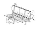
- FIG. 1is a perspective view of one embodiment of the present invention.
- FIG. 2is a top view of one embodiment of the present invention.
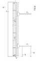
- FIG. 3is a side view in one embodiment of the present invention.
- FIG. 4is an opposite side view in one embodiment of the present invention.
- FIG. 5is a front view of one embodiment of the present invention.
- FIG. 6is a back view of one embodiment of the present invention.
- FIG. 7is a perspective view of one embodiment of the present invention with emphasis depicting the arm members for supporting Zee-channels or C-channels.
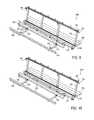
- FIG. 8is a perspective view of one embodiment of the present invention depicting one Zee-channel attached to the arm members.
- FIG. 9is a perspective view of one embodiment of the present invention depicting two Zee-channels attached to the arm members.
- FIG. 10is an alternate perspective view of one embodiment of the present invention depicting two Zee-channels attached to the arm members.
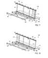
- FIG. 11is a perspective view of one embodiment of the present invention depicting two Zee-channels attached to the arm members and one solar panel resting in the track member.
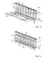
- FIG. 12is a perspective view of one embodiment of the present invention depicting two Zee-channels attached to the arm members and one solar panel resting in the opposite end of the track member.
- FIG. 13is a perspective view of one embodiment of the present invention depicting two Zee-channels attached to the arm members and a plurality of solar panel resting in the track member.
- FIG. 14is a perspective view of one embodiment of the present invention depicting two Zee-channels attached to the arm members and a plurality of solar panel resting in the track member, and the arm members partially folded/rotated upward towards the Zee-channels/support member.
- FIG. 15is a perspective view of one embodiment of the present invention depicting two Zee-channels attached to the arm members and a plurality of solar panel resting in the track member, and the arm members fully folded/rotated upward towards the Zee-channels/support member, so as to place the Zee-channels in position to be attached to the plurality of solar panels.
- FIG. 16is a perspective view of one embodiment of the present invention depicting two Zee-channels attached to the arm members and a plurality of solar panel resting in the track member, and the arm members fully folded/rotated upward towards the two Zee-channels/support member, with the Zee-channels attached to the plurality of solar panels, and a pallet structure in position to receive the two Zee-channels attached to the plurality of solar panels.
- FIG. 17is a perspective view of one embodiment of the present invention depicting the two Zee-channels attached to the plurality of solar panels and supported by the pallet structure.
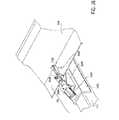
- FIG. 18is a perspective view of one embodiment of the present invention depicting the two Zee-channels attached to the plurality of solar panels, released from the arm members, supported by the pallet structure, and in position to be picked up by a fork lift.
- FIG. 19is a perspective view of one embodiment of the present invention depicting the two Zee-channels attached to the plurality of solar panels, released from the arm members, supported by the pallet structure, and being removed by a fork lift for loading on a truck to take to the job site.
- FIG. 20is a perspective view of one embodiment of the pallet structure of the present invention.
- FIG. 21is a top view of one embodiment of the pallet structure of the present invention.
- FIG. 22is a side view of one embodiment of the pallet structure of the present invention.
- FIG. 23is an end view of one embodiment of the pallet structure of the present invention.
- FIG. 24is a perspective view of one embodiment of multiple stacked pallet structures of the present invention with completed Zee-channels attached to a plurality of solar panels loaded on each pallet structure.
- FIG. 25is a perspective view of one embodiment of the clamp structure of the present invention.
- FIG. 26is an alternate perspective view of one embodiment of the clamp structure of the present invention.
- the “solar panel support channels”comprise “Z”-shaped sheet metal, also referred to as “Zee-channels” or “7-channels”, “C”-shaped sheet metal, also referred to as “Cee-channels” or “c-channels”, or standard beams, bars, and other suitable support members.
- FIG. 1is a perspective view of one embodiment of the present invention.
- the inventionincludes an apparatus 100 for pre-assembly of an electrically connected array of solar panels for a solar canopy.
- Base member 110(having longitudinal and lateral side portions) is for resting on any solid stable horizontal surface capable of supporting the weight of the apparatus, workers, and solar panels to be assembled.
- the base member 110is substantially planar.
- wheels 190are attached at the bottom of base member 110 to allow repositioning of the apparatus 100 .
- support member 120is self-supporting or supported, e.g., by attachment to a wall, floor or other fixture, or by placement of “post” legs at the bottom of the support member into “post” holes in the floor.
- the support member 120is self supporting due to its shape, e.g., box-shaped or triangle shaped.
- a support member 120is fixedly or removably attached to base member 110 and is for horizontally aligning side-by-side and horizontally supporting a plurality of solar panels when a photo-voltaic cell side of the solar panels rests against the support member 120 .
- the support member 120is substantially planar.
- a bottom portion of support member 120is integral with the base member or fixed attached to the base member 110 , and the support member 120 extends upward from the base member 110 .
- the support member 120is inclined from vertical sufficiently for supporting the solar panels. In one embodiment the support member 120 is inclined from about 3 degrees to about 25 degrees from vertical.
- support member 120is comprised of a lattice framework.
- a solid formis another option, e.g. molded plastic or forged metal.
- a track member 140is disposed proximate a bottom portion of the support member 120 and is attached to or integral with the support member 120 or base member 110 for vertically aligning side-by-side and vertically supporting a plurality of solar panels when a side edge portion of the solar panels rests on the track member 140 .
- At least two arm members 130each having a free end and an attached end, the attached ends pivotally attached proximate to opposing ends of the base member 110 or support member 120 .
- one end of arm members 130is attached to pivot bar 150 (also referred to as shaft member) and the opposing ends of pivot bar 150 are attached to brackets on opposing ends of base member 110 .
- Each arm members 130having a longitudinal axis oriented substantially perpendicular to the longitudinal axis of the base member 110 and pivot bar 150 and extend outward from the base member 110 .
- the arm members 130are configured to pivot in a vertical plane from a position substantially parallel to the ground upward to a position substantially parallel to parallel to the plane of the support member 120 .
- the arm members 130are configured and adapted for removably attaching at least two solar panel support channels (see FIGS. 13 and 14 ). Also, the arm members 130 in one embodiment are configured and adapted for removably attaching at least two solar panel support channels 810 (see FIG. 8 ) at multiple positions and spacing along the longitudinal axis of arm members 130 so as to be suitable for use with a plurality of solar panel sizes. In one embodiment arms 130 are movable and may be adjusted along pivot bar 150 for different size solar panel arrays. Also, in another embodiment arm members 130 may be folded towards and against pivot bar 150 to allow for more easy transportation of the apparatus 100 .
- one or more alignment beams 160are attached to one of the arm members 130 .
- Alignment beams 160have a free end and a fixed end where the fixed end is movably attached perpendicularly to an arm member 130 at one end of assembly 100 and extending away from other arm members 130 , i.e., in longitudinal alignment with the base member 110 .
- Alignment beams 160are configured and adapted for aligning and preventing lateral movement of a solar panel support channels (see FIGS. 9 and 10 ), wherein the alignment beam is adjustable along the length of the arm member to suit various solar panel sizes.
- alignment beams 160may be folded towards and against arm members 130 to allow for more easy transportation of the apparatus 100 .
- a tool rail 170is attached via tool rail support arms 175 to a top portion of support member 120 and is parallel to it. It is configured to receive a movable tool caddy 180 which can be slide along the tool rail 170 by a technician and has a hook, strap or other device for holding a tool such as an electric drill or riveter.
- the tool rail 170 and tool caddy 180reduces the lifting and moving work of the technician of heavy tools.
- FIG. 2is a top view of one embodiment of the present invention 200 .
- An additional optional element more clearly shown in this figureis brace members 210 which attach to arm members 130 and pivot bar 150 where the two are joined.
- FIG. 3is a side view in one embodiment of the present invention 300 . More clearly shown in this figure is the track in tool rail 170 in which tool caddy 180 may slide. Also this side view more clearly shows one end of pivot bar 150 where it is rotatably attached to base member 110 . More than one tool caddy 180 may be slid on tool rail 170 , e.g., one for each technician working on the assembly.
- FIG. 4is an opposite side view in one embodiment of the present invention 400 .
- FIG. 5is a front view of one embodiment of the present invention 500 . This view more clearly shows a plurality of optional wheels 190 attached at the bottom of base member 110 to allow easy relocation of the apparatus 500 .
- FIG. 6is a back view of one embodiment of the present invention 600 .
- FIG. 7is a perspective view of one embodiment of the present invention 700 with emphasis on depicting the arm members 130 for supporting Zee-channels or C-channels. Also this figure more clearly shows a base member protrusion 710 and “C” bracket 720 for securing each end of pivot bar 150 . Also this figure depicts clamp member 730 attached to arm members 130 for removably attaching, e.g., a Zee-channel (shown in FIG. 8 ). For each Zee-channel used in the assembly of a solar module array there are at least two corresponding clamp members 730 , i.e., one for attaching the Zee-channel to each of the preferably at least two arm members 130 . Any known clamping structure may be used, e.g., screw-down clamp, magnetic clamp, bar and clasp clamp, bar and lock clamp, to hold the Zee-channel during assembly and to release the solar module array at the Zee-channel after assembly is completed.
- Any known clamping structuremay be used, e.g., screw-down clamp
- the clamp members 730are preferably attached to respective arm members 130 at equal distances from the pivot bar 150 so as to allow attaching the Zee-channels parallel to the longitudinal access of the base member 110 . Where optional alignment beams 160 are attached to arm members 130 , the clamp members are positioned so that when a Zee-channel is attached via a clamp member 730 one end of the Zee-channel rests along the alignment beam 160 and abuts its end portion, thus easily positioning the Zee-channel for attachment to the bottom of solar panels (see FIGS. 13 and 14 ).
- FIG. 8is a perspective view of one embodiment of the present invention 800 depicting one Zee-channel 810 attached via clamp members 730 to the arm members 130 .
- One end of the Zee-channel 810rests along the alignment beam 160 and abuts its end portion.
- FIG. 9is a perspective view of one embodiment of the present invention 900 depicting two Zee-channels 810 attached to the arm members 130 , both having one end resting along an alignment beam 160 and abutting an end portion of the alignment beam.
- FIG. 10is an alternate perspective view of one embodiment of the present invention 1000 depicting two Zee-channels 810 attached to the arm members 130 , both having one end resting along an alignment beam 160 and abutting an end portion of the alignment beam.
- FIG. 11is a perspective view of one embodiment of the present invention 1100 depicting two Zee-channels 810 attached to the arm members and one solar panel 1110 resting in the track member 140 .
- the solar panel 1110has a bottom portion supported by resting in track member 140 and upper portion supported by leaning against support member 120 .
- FIG. 12is a perspective view of one embodiment of the present invention 1200 depicting two Zee-channels attached to the arm members 130 and one solar panel 1110 resting in the opposite end of the track member 140 from that shown in FIG. 11 .
- This modewould be convenient where the supply of solar panels 1110 is stacked on that side of the apparatus. Then each solar panel is slide to the opposite end of the track member 140 and support member 120 and this is repeated until a sufficient number of solar panels have been placed on the apparatus.
- solar panels 1110could be feed from both ends of the track member 140 and support member 120 , either alternately or simultaneously depending on available number of technicians and placement of solar panel stock.
- FIG. 13is a perspective view of one embodiment of the present invention 1300 depicting two Zee-channels 810 attached to the arm members 130 and a plurality of solar panels 1110 resting in the track member 140 and against support member 120 . The plurality of solar panels is now positioned for attachment of the Zee-channels 810 .
- FIG. 14is a perspective view of one embodiment of the present invention 1400 depicting two Zee-channels 810 attached to the arm members 130 and a plurality of solar panels 1110 resting in the track member 140 and against support member 120 , and the arm members 130 partially folded/rotated upward towards the support member 120 .
- FIG. 15is a perspective view of one embodiment of the present invention 1500 depicting two Zee-channels 810 attached to the arm members 130 and a plurality of solar panels 1110 resting in the track member 140 and against support member 120 , and the arm members 130 folly folded/rotated upward towards the support member 120 and bottom of solar panels 1110 and in contact with the bottom of solar panels 1110 and therefore positioned for attachment to the solar panels 1110 so as to place the Zee-channels 810 in position to be attached to the plurality of solar panels 1110 .
- the positioning of the tool rail 170is above the height of arm members 130 when folly folded so as not to interfere with their folding.
- FIG. 16is a perspective view of one embodiment of the present invention 1600 depicting two Zee-channels 810 attached to the arm members 130 and a plurality of solar panels 1110 resting in the track member 140 , and the arm members 130 fully folded/rotated upward towards the two support member 120 , with the Zee-channels 810 now attached to the plurality of solar panels 1110 , and a pallet structure 1610 in position to receive the newly assembled solar module array 1710 (consisting of two Zee-channels 810 attached to the plurality of solar panels 1110 ).
- the pallet structure 1610is properly positioned to receive the solar module array 1710 by abutting one side of pallet structure 1610 against pivot bar 150 .
- FIG. 17is a perspective view of one embodiment of the present invention 1700 depicting the solar module array 1710 supported by the pallet structure.
- FIG. 18is a perspective view of one embodiment of the present invention 1800 depicting the solar module array 1710 , released via clamp member 730 from the arm members 130 , supported by the pallet structure 1610 , and in position to be picked up by a fork lift 1810 .
- FIG. 19is a perspective view of one embodiment of the present invention 1900 depicting the solar module array 171 . 0 , released via clamp member 730 from the arm members 130 , supported by the pallet structure 1610 , and being removed by a fork lift 1810 for loading on a truck to take to the job site.
- FIG. 20is a perspective view of one embodiment of the pallet structure/assembly 2000 of the present invention.
- the pallet assembly 2000is configured and adapted for supporting the solar module array 1710 , which in one embodiment is electrically connected array of a plurality of solar panels 1110 fixedly attached to Zee-channels 810 during storage and transport.
- the pallet assembly 2000comprises a deck 2010 (comprised of beam members 2060 and 2050 joined); a plurality of feet 2020 extending downward from the deck a sufficient depth to allow for stacking of multiple pallet assemblies 2000 with one solar module array 1710 loaded on each pallet assembly 2000 , i.e., at least the thickness of one solar module array 1710 plus any additional depth needed for stacking; a plate (not shown) attached to an edge portion of the deck 2010 , for aligning the pallet assembly 2000 with the apparatus 100 (see e.g., FIG.
- deck 2010 and feet 2020could include, e.g., a single integral molded plastic form, a solid deck or molded deck 2010 attached to feet 2020 , a box-type structure with a bottom recess to provide space for stacking, or detachable legs that, e.g., are temporarily attached to a portion of a solar module array 1710 .
- FIG. 21is a top view of one embodiment of the pallet assembly 2000 of the present invention
- FIG. 22is a side view of one embodiment of the pallet assembly 2000 of the present invention
- FIG. 23is an end view of one embodiment of the pallet assembly of the present invention.
- FIG. 24is a perspective view of one embodiment of multiple stacked pallet assemblies 2000 of the present invention with completed solar module arrays 1710 loaded on each pallet structure.
- the upper portion and lower portions of feet 2020shown at the 4 corners of the pallet assemblies in this embodiment, are configured and adapted for stacking by any known methods, e.g., having a recess on the upper portion and a matching protrusion on the lower portion of each foot 2020 so the feet align and stack securely when one pallet assembly is stacked on top of another pallet assembly.
- Alternative embodimentsmight include a locking latch member, snap latches, or other known connecting mechanisms.
- FIG. 25is a perspective view of one embodiment of the clamp structure 730 of the present invention 2500 .
- a base bracket 2525is optionally used to fixedly or movably attach clamp structure 730 to arm member 130 .
- Pressure pin member 2560contacts an edge portion of Zee-channel 810 and “pins” the Zee-channel to arm member 130 .
- FIG. 26is an enlarged alternate perspective view of one embodiment of the clamp structure 730 of the present invention.
- Clamp base 2535is fixedly attached to base bracket 2525 .
- a pneumatic, hydraulic, electric, or manually powered ram 2520is actuated to cause piston 2530 to move forward or backward in ram 2520 .
- the movement of piston 2530 in rotatable coupling with hinge 2540moves pin bracket 2550 open or closed, i.e., up or down, thereby causing pressure pin member 2560 to pin or release the Zee-channel 810 .
- Various other clamp mechanisms and clamp actuating mechanismsmay be used and are within the scope of the invention.
Landscapes
- Engineering & Computer Science (AREA)
- General Engineering & Computer Science (AREA)
- Mechanical Engineering (AREA)
- Physics & Mathematics (AREA)
- Life Sciences & Earth Sciences (AREA)
- Sustainable Development (AREA)
- Sustainable Energy (AREA)
- Thermal Sciences (AREA)
- Chemical & Material Sciences (AREA)
- Combustion & Propulsion (AREA)
- Photovoltaic Devices (AREA)
Abstract
Description
- (a) a support member for aligning side-by-side a plurality of solar panels with a bottom portion of the solar panels exposed; and
- (b) an arm member attached at one longitudinal end portion proximate to the side portion of the support member and configured and adapted for removably attaching at least two solar panel support channels.
- (a) a base member horizontally disposed for supporting other elements;
- (b) a support member having attached along one side portion of the support member to the base member and an opposing side portion disposed away from the base member for aligning side-by-side a plurality of solar panels with a bottom portion of the solar panels exposed; and
- (c) an arm member attached at one longitudinal end portion proximate to the side portion of the support member attached to the base member and configured and adapted for removably attaching at least two solar panel support channels.
- (a) a substantially planar base member for resting on a horizontal surface,
- (b) a substantially planar support member for horizontally aligning side-by-side and horizontally supporting a plurality of solar panels when a photo-voltaic cell side of the solar panels rests against the support member, wherein a bottom portion of the support member is integral with the base member or fixed attached to the base member, and the support member extends upward from the planar base member;
- (c) a track member disposed proximate a bottom portion of the support member attached to or integral with the support member or base member for vertically aligning side-by-side and vertically supporting a plurality of solar panels when a side edge portion of the solar panels rests on the track member; and
- (d) at least two arm members, each having a free end and an attached end, the attached ends pivotally attached proximate to opposing ends of the base member or support member and each arm members having a longitudinal axis oriented substantially perpendicular to the longitudinal axis of the base member and support member and extending outward from the base member and support member, and configured to pivot in a vertical plane from a position substantially parallel to the ground upward to a position substantially parallel to the plane of the support member, wherein upon pivoting in one direction the free end moves closer towards the support member and pivoting in the other direction the free end moves away from the support member, the arm members being configured and adapted for removably attaching at least two solar panel support channels.
- (a) aligning a plurality of solar panels side-by-side in an electrically connected array of solar panels pre-assembly apparatus, the pre-assembly apparatus comprising:
- a base member for resting on a horizontal surface;
- a support member for horizontally aligning side-by-side and horizontally supporting a plurality of solar panels when a photo-voltaic cell side of the solar panels rests against the support member, wherein a bottom portion of the support member is integral with the base member or fixed attached to the base member, and the support member extends upward from the base member;
- a track member disposed proximate a bottom portion of the support member attached to or integral with the support member or base member for vertically aligning side-by-side and vertically supporting a plurality of solar panels when a side edge portion of the solar panels rests on the track member; and
- at least two arm members, each having a free end and an attached end, the attached ends pivotally attached proximate to opposing ends of the base member or support member and each arm members having a longitudinal axis oriented substantially perpendicular to the longitudinal axis of the base member and support member and extending outward from the base member, and support member, and configured to pivot in a vertical plane from a position substantially parallel to the ground upward to a position substantially parallel to parallel to the plane of the support member, wherein upon pivoting in one direction the free end moves closer towards the support member and pivoting in the other direction the free end moves away from the support member, the arm members being configured and adapted for removably attaching at least two solar panel support channels;
- wherein a bottom portion of the plurality of solar panels is supported by the track member and a front portion is supported by the support member, facing inward towards the base member;
- (b) removably attaching at least two solar panel support channels to the arm members of the solar panel array pre-assembly apparatus, wherein the longitudinal axis of the solar panel support channels is parallel to the longitudinal axis of the base member and positioned to contact a bottom portion of all of the plurality of solar panels, near opposite longitudinal ends of each of the plurality of solar panels when the arm members are rotated about the longitudinal axis of the base member where attached;
- (c) manipulating the position of the arm members of the electrically connected array of solar panels pre-assembly apparatus relative to position of the support member of the electrically connected array of pre-assembly apparatus such that the solar panel support channels contacts a bottom portion of the plurality of solar panels, near opposite longitudinal ends of each of the plurality of solar panels, thereby aligning the solar panel support channels for attachment to bottom of the plurality of solar panels;
- (d) fixedly attaching a top portion of the solar panel support channels to a bottom portion of each of the plurality of solar panels; and
- (e) reversing the manipulation in step (c) of the position of the arm members of the solar panel array pre-assembly apparatus relative to position of the support member of the pre-assembly apparatus, such that the plurality of solar panels and attached solar panel support channels lay parallel with the ground surface and are ready to be loaded on a truck for transportation to the job site.
Claims (10)
Priority Applications (5)
| Application Number | Priority Date | Filing Date | Title |
|---|---|---|---|
| US13/112,314US8584338B2 (en) | 2010-05-24 | 2011-05-20 | Solar module array pre-assembly method |
| US14/055,978US20140175251A1 (en) | 2010-05-24 | 2013-10-17 | Solar module array pre-assembly method and apparatus |
| US14/088,040US20140076383A1 (en) | 2010-05-24 | 2013-11-22 | Solar module array pre-assembly method and apparatus |
| US15/444,426US20170167756A1 (en) | 2010-05-24 | 2017-02-28 | Solar module array pre-assembly method and apparatus |
| US15/450,597US10584901B2 (en) | 2010-05-24 | 2017-03-06 | Solar module array pre-assembly method and apparatus |
Applications Claiming Priority (2)
| Application Number | Priority Date | Filing Date | Title |
|---|---|---|---|
| US34752310P | 2010-05-24 | 2010-05-24 | |
| US13/112,314US8584338B2 (en) | 2010-05-24 | 2011-05-20 | Solar module array pre-assembly method |
Related Child Applications (2)
| Application Number | Title | Priority Date | Filing Date |
|---|---|---|---|
| US14/055,978DivisionUS20140175251A1 (en) | 2010-05-24 | 2013-10-17 | Solar module array pre-assembly method and apparatus |
| US14/088,040Continuation-In-PartUS20140076383A1 (en) | 2010-05-24 | 2013-11-22 | Solar module array pre-assembly method and apparatus |
Publications (2)
| Publication Number | Publication Date |
|---|---|
| US20110284709A1 US20110284709A1 (en) | 2011-11-24 |
| US8584338B2true US8584338B2 (en) | 2013-11-19 |
Family
ID=44971698
Family Applications (3)
| Application Number | Title | Priority Date | Filing Date |
|---|---|---|---|
| US13/112,314Active2031-12-28US8584338B2 (en) | 2010-05-24 | 2011-05-20 | Solar module array pre-assembly method |
| US14/055,978AbandonedUS20140175251A1 (en) | 2010-05-24 | 2013-10-17 | Solar module array pre-assembly method and apparatus |
| US15/450,597Active2032-01-31US10584901B2 (en) | 2010-05-24 | 2017-03-06 | Solar module array pre-assembly method and apparatus |
Family Applications After (2)
| Application Number | Title | Priority Date | Filing Date |
|---|---|---|---|
| US14/055,978AbandonedUS20140175251A1 (en) | 2010-05-24 | 2013-10-17 | Solar module array pre-assembly method and apparatus |
| US15/450,597Active2032-01-31US10584901B2 (en) | 2010-05-24 | 2017-03-06 | Solar module array pre-assembly method and apparatus |
Country Status (1)
| Country | Link |
|---|---|
| US (3) | US8584338B2 (en) |
Cited By (9)
| Publication number | Priority date | Publication date | Assignee | Title |
|---|---|---|---|---|
| US20110283923A1 (en)* | 2010-05-24 | 2011-11-24 | CHEVRON ENERGY SOLUTIONS COMPANY, a division of CHEVRON U.S.A. INC. | Pallet assembly for transport of solar module array pre-assembly |
| US9093583B2 (en) | 2012-09-19 | 2015-07-28 | Opterra Energy Services, Inc. | Folding solar canopy assembly |
| US9093582B2 (en) | 2012-09-19 | 2015-07-28 | Opterra Energy Services, Inc. | Solar canopy assembly |
| US9568900B2 (en) | 2012-12-11 | 2017-02-14 | Opterra Energy Services, Inc. | Systems and methods for regulating an alternative energy source that is decoupled from a power grid |
| US9774293B2 (en) | 2012-09-19 | 2017-09-26 | Opterra Energy Services, Inc. | Bracing assembly |
| US20230077373A1 (en)* | 2008-11-17 | 2023-03-16 | Kbfx Llc | Finished multi-sensor units |
| US11891236B2 (en) | 2020-02-25 | 2024-02-06 | Pvpallet, Inc. | Transport container |
| US11938576B1 (en) | 2022-12-20 | 2024-03-26 | Terabase Energy, Inc. | Systems and methods for threading a torque tube through U-bolt and module rail devices |
| US11999284B2 (en) | 2021-09-01 | 2024-06-04 | Terabase Energy, Inc. | Solar table mobile transport |
Families Citing this family (11)
| Publication number | Priority date | Publication date | Assignee | Title |
|---|---|---|---|---|
| US8365479B2 (en) | 2011-06-17 | 2013-02-05 | Phat Energy Corporation | Solar power structure |
| US9033645B2 (en)* | 2012-07-31 | 2015-05-19 | Shenzhen China Star Optoelectronics Technology Co., Ltd. | Liquid crystal panel transportation device and support arm structure with rotatable ancillary arm sections |
| US20150372635A1 (en)* | 2014-06-23 | 2015-12-24 | Miguel M.L. Praca | Modular roof mounting system for photovoltaic panels |
| US10658534B2 (en)* | 2019-01-31 | 2020-05-19 | Jinjie Gu | Bi-facial photovoltaic power generation module |
| WO2020161714A1 (en)* | 2019-02-06 | 2020-08-13 | Xfloat Ltd. | Controlled floating solar module |
| US10801755B1 (en)* | 2019-05-31 | 2020-10-13 | Nemat, Inc. | Apparatuses and methods for simplified installation of solar panels |
| US10863646B1 (en)* | 2019-07-18 | 2020-12-08 | M.C. Dean, Inc. | Modular data center support rack system and installation method |
| USD923561S1 (en)* | 2020-01-08 | 2021-06-29 | René Jozef Timmerman | Solar panel array |
| US20230238912A1 (en)* | 2022-01-22 | 2023-07-27 | Terabase Energy, Inc. | Centralized solar table assembly |
| US12410020B2 (en) | 2022-09-14 | 2025-09-09 | Gridworks Technology, LLC | Systems and methods for installation of solar panel assemblies |
| US12218623B1 (en) | 2024-07-19 | 2025-02-04 | DoubleLand LLC | Systems and methods for multi-position solar panel arrays |
Citations (24)
| Publication number | Priority date | Publication date | Assignee | Title |
|---|---|---|---|---|
| US3620846A (en)* | 1970-04-08 | 1971-11-16 | Nasa | Deployable solar cell array |
| US3946876A (en) | 1974-03-18 | 1976-03-30 | Jarke Corporation | Hinged post storage rack |
| US4015653A (en)* | 1976-04-08 | 1977-04-05 | General Dynamics Corporation | Panel deployment system |
| US4151872A (en)* | 1977-12-21 | 1979-05-01 | General Dynamics Corporation | Panel deployment system |
| US4206748A (en)* | 1978-05-25 | 1980-06-10 | Libbey-Owens-Ford Company | Solar energy collector with collapsible supporting structure |
| US5233931A (en) | 1992-03-20 | 1993-08-10 | The Edinborough Company | Tray for transport and display of merchandise |
| US5433259A (en) | 1993-11-22 | 1995-07-18 | Carefree/Scott Fetzer Company | Retractable awning with integrated solar cells |
| US20060219547A1 (en) | 2004-11-10 | 2006-10-05 | Daystar Technologies, Inc. | Vertical production of photovoltaic devices |
| US20080029148A1 (en) | 2004-10-29 | 2008-02-07 | Thompson Daniel S | Floating support structure for a solar panel array |
| US20080230047A1 (en) | 2007-03-23 | 2008-09-25 | Sunpower Corporation | Stackable Tracking Solar Collector Assembly |
| US7487771B1 (en) | 2004-09-24 | 2009-02-10 | Imaginit, Inc. | Solar panel frame assembly and method for forming an array of connected and framed solar panels |
| US20090230265A1 (en) | 2008-03-17 | 2009-09-17 | Michael Newman | Mounting System for Photovoltaic Panels |
| US20100077592A1 (en) | 2008-10-01 | 2010-04-01 | Peter Casano | System and method for hanging solar panels from a horizontal support |
| US20100108118A1 (en) | 2008-06-02 | 2010-05-06 | Daniel Luch | Photovoltaic power farm structure and installation |
| US20100132769A1 (en) | 2009-10-23 | 2010-06-03 | Chevron U.S.A. Inc. | Solar canopy support system |
| US20100163015A1 (en) | 2009-10-23 | 2010-07-01 | Chevron U.S.A. Inc. | Solar canopy connector system |
| US7766292B2 (en) | 2001-07-20 | 2010-08-03 | Unirac, Inc. | System for mounting a photovoltaic module to a surface |
| US20100193260A1 (en)* | 2009-02-03 | 2010-08-05 | Benjamin Freeman | Electric car with maximized solar assist |
| US20100237029A1 (en) | 2009-03-20 | 2010-09-23 | Northern States Metals Company | Support System For Solar Panels |
| US20100236183A1 (en) | 2009-03-20 | 2010-09-23 | Northern States Metals Company | Support System for Solar Panels |
| US7856769B2 (en) | 2004-02-13 | 2010-12-28 | Pvt Solar, Inc. | Rack assembly for mounting solar modules |
| US20110047931A1 (en) | 2008-05-01 | 2011-03-03 | Sunedison, Llc | Methods of Assembling Solar Energy Collecting Modules |
| US20110240093A1 (en)* | 2011-06-17 | 2011-10-06 | Phat Energy | Solar power structure |
| US20110283923A1 (en)* | 2010-05-24 | 2011-11-24 | CHEVRON ENERGY SOLUTIONS COMPANY, a division of CHEVRON U.S.A. INC. | Pallet assembly for transport of solar module array pre-assembly |
Family Cites Families (55)
| Publication number | Priority date | Publication date | Assignee | Title |
|---|---|---|---|---|
| US2520196A (en)* | 1948-08-06 | 1950-08-29 | Gardiner S Boone | Transferring device |
| FR1438399A (en)* | 1965-03-29 | 1966-05-13 | Saint Gobain | Improvements to stacking sheets on a desk |
| US3517834A (en)* | 1968-06-17 | 1970-06-30 | Adams Co J D | Building component stacking system |
| USRE28609E (en)* | 1969-02-13 | 1975-11-11 | Apparatus for handling fragile sheets | |
| US3751794A (en)* | 1971-08-13 | 1973-08-14 | C Kay | Panel assembly and machine |
| US3811578A (en)* | 1972-09-19 | 1974-05-21 | Automatic Building Components | Apparatus for unloading and stacking wooden structural frames |
| US3984010A (en)* | 1975-09-15 | 1976-10-05 | Boise Cascade Corporation | Truss stacking apparatus |
| FR2370662A1 (en)* | 1976-11-15 | 1978-06-09 | Saint Gobain | COMPACT FOLDING DEVICE ONE OVER THE OTHER OF TWO PLATE OBJECTS |
| US4403388A (en)* | 1980-03-17 | 1983-09-13 | Belcher Roy L | Automatic pallet-making machine and method |
| US4372027A (en)* | 1980-04-03 | 1983-02-08 | Solar Kinetics, Inc. | Method of manufacturing parabolic trough solar collector |
| US4423719A (en)* | 1980-04-03 | 1984-01-03 | Solar Kinetics, Inc. | Parabolic trough solar collector |
| US4383680A (en)* | 1980-11-25 | 1983-05-17 | Richard Braceland | Jig for assembling table tops |
| US4492016A (en)* | 1982-09-16 | 1985-01-08 | Smetco, Inc. | Pallet assembly apparatus and method |
| US4623083A (en)* | 1984-08-06 | 1986-11-18 | Pagano Anthony L | Pivotal fixture apparatus for fabricating board on board fence sections |
| JPH074705B2 (en)* | 1987-08-19 | 1995-01-25 | 秀昭 白井 | Two-by-two construction method of wooden house panel and standing storage method and device |
| US5620293A (en)* | 1995-08-07 | 1997-04-15 | Vidrio Plano De Mexico | Glass sheet handling apparatus |
| US6111189A (en) | 1998-07-28 | 2000-08-29 | Bp Solarex | Photovoltaic module framing system with integral electrical raceways |
| US6499206B1 (en)* | 2000-05-18 | 2002-12-31 | Karl Matthew Eure | Apparatus and method for manufacturing pallets |
| US6553653B2 (en)* | 2000-06-23 | 2003-04-29 | Billco Manufacturing, Inc. | Vertical assembly table |
| US6559371B2 (en) | 2001-06-27 | 2003-05-06 | Pinnacle West Capital Corp. | High-concentration photovoltaic assembly for a utility-scale power generation system |
| DE10148038A1 (en)* | 2001-09-28 | 2003-04-17 | Grenzebach Maschb Gmbh | Device for transferring plates from a plate conveyor to a stacking frame or the like |
| US6672018B2 (en) | 2001-10-12 | 2004-01-06 | Jefferson Shingleton | Solar module mounting method and clip |
| US6969054B2 (en)* | 2001-11-08 | 2005-11-29 | Mitek Holdings, Inc. | Receiving stand for frame stacking system |
| US6757956B2 (en)* | 2002-02-21 | 2004-07-06 | Denver Mattress Co., Llc | System and methods for constructing box spring/foundation frames |
| CA2421121A1 (en)* | 2003-03-13 | 2004-09-13 | Roger Mercure | Device and method for valuing and optimizing cutout panels |
| ES2288653T3 (en) | 2004-07-12 | 2008-01-16 | Haberlein-Lehr, Ulla | MODULAR ASSEMBLY SYSTEM FOR THE SAFE ACCOMMODATION OF PHOTOVOLTAIC MODULES STACKED HORIZONTALLY DURING TRANSPORTATION. |
| US7658055B1 (en) | 2006-10-01 | 2010-02-09 | Nanosolar, Inc. | Method of packaging solar modules |
| US20100294340A1 (en) | 2007-06-19 | 2010-11-25 | Cunningham Daniel W | Solar Module with a Frame for Mounting a Solar panel |
| FR2922365B1 (en)* | 2007-10-16 | 2009-12-18 | Avancis Gmbh & Co Kg | IMPROVEMENTS TO ELEMENTS CAPABLE OF COLLECTING LIGHT. |
| WO2009129422A2 (en) | 2008-04-16 | 2009-10-22 | Stnacel, Robert | Methods and devices for shipping solar modules |
| JP2010045346A (en)* | 2008-07-24 | 2010-02-25 | Bp Corp North America Inc | Adjustable interlocking solar module and method of installation |
| US8677701B2 (en)* | 2008-09-25 | 2014-03-25 | The Boeing Company | Attaching solar collectors to a structural framework utilizing a flexible clip |
| US20100218441A1 (en) | 2008-11-26 | 2010-09-02 | Robert Stancel | Wind Uplift Resistant Module Mounting System |
| US8567132B2 (en) | 2009-02-20 | 2013-10-29 | Elie Rothschild | Modular solar racking system |
| US8316590B2 (en) | 2009-03-20 | 2012-11-27 | Northern States Metals Company | Support system for solar panels |
| US8156697B2 (en) | 2009-10-15 | 2012-04-17 | Sunlink Corporation | Photovoltaic module mounting system |
| DE202009015110U1 (en) | 2009-11-06 | 2011-03-24 | Häberlein-Lehr, Ulla | Bracket and modular stacking system for safe storage and / or transportation of frameless PV modules or other flat cuboidal bodies |
| US20110108093A1 (en)* | 2009-11-12 | 2011-05-12 | General Electric Company | Frame assembly for a photovoltaic panel |
| US20120222372A1 (en) | 2009-11-18 | 2012-09-06 | Hilber Franz | Adjusting device of a stationary photovoltaic system |
| JP5210336B2 (en) | 2010-02-10 | 2013-06-12 | シャープ株式会社 | PV panel protection module |
| US8328020B2 (en) | 2010-03-10 | 2012-12-11 | Eckpack Service Gmbh & Co. Kg | Holding system for horizontally or vertically stacking framed photovoltaic or solar thermal flat modules |
| US20140076383A1 (en) | 2010-05-24 | 2014-03-20 | Chevron U.S.A. Inc. | Solar module array pre-assembly method and apparatus |
| US20120027550A1 (en) | 2010-07-29 | 2012-02-02 | John Bellacicco | Automated installation system for and method of deployment of photovoltaic solar panels |
| US20120031787A1 (en) | 2010-08-08 | 2012-02-09 | Miasole | Package for shipping and storing photovoltaic panel products |
| WO2012030762A2 (en) | 2010-08-30 | 2012-03-08 | First Solar, Inc | Solar module protector |
| JP5924471B2 (en) | 2010-09-30 | 2016-05-25 | キョーラク株式会社 | Module used for stacking thin panel and method for stacking thin panel |
| CN103228545B (en) | 2010-11-29 | 2015-07-22 | 京洛株式会社 | Rectangular thin panel conveyance unit |
| JP5220962B2 (en) | 2010-12-16 | 2013-06-26 | 株式会社日立物流 | Module used for stacking thin panels |
| JP5736630B2 (en) | 2010-12-25 | 2015-06-17 | キョーラク株式会社 | Module used for stacking thin panel and method for stacking thin panel |
| US20120174967A1 (en) | 2011-01-10 | 2012-07-12 | NuvoSun, Inc. | Photovoltaic modules and mounting systems |
| US20140360552A1 (en) | 2012-07-19 | 2014-12-11 | Brittmore Group LLC | Solar Panel Field Array Support System and Apparatus and Method for Construction Use |
| TWI464096B (en) | 2011-10-12 | 2014-12-11 | San Ho Paper & Carton Co Ltd | Solar panel crates |
| US8850754B2 (en) | 2011-10-17 | 2014-10-07 | Dynoraxx, Inc. | Molded solar panel racking assembly |
| US9130088B2 (en) | 2011-11-08 | 2015-09-08 | Apollo Precision Fujian Limited | Solar panel with integrated mounting clip/shipping support |
| CN104125920A (en) | 2011-12-21 | 2014-10-29 | 夏普株式会社 | Support structure, loading and packing device, support substrate, and packing method |
- 2011
- 2011-05-20USUS13/112,314patent/US8584338B2/enactiveActive
- 2013
- 2013-10-17USUS14/055,978patent/US20140175251A1/ennot_activeAbandoned
- 2017
- 2017-03-06USUS15/450,597patent/US10584901B2/enactiveActive
Patent Citations (24)
| Publication number | Priority date | Publication date | Assignee | Title |
|---|---|---|---|---|
| US3620846A (en)* | 1970-04-08 | 1971-11-16 | Nasa | Deployable solar cell array |
| US3946876A (en) | 1974-03-18 | 1976-03-30 | Jarke Corporation | Hinged post storage rack |
| US4015653A (en)* | 1976-04-08 | 1977-04-05 | General Dynamics Corporation | Panel deployment system |
| US4151872A (en)* | 1977-12-21 | 1979-05-01 | General Dynamics Corporation | Panel deployment system |
| US4206748A (en)* | 1978-05-25 | 1980-06-10 | Libbey-Owens-Ford Company | Solar energy collector with collapsible supporting structure |
| US5233931A (en) | 1992-03-20 | 1993-08-10 | The Edinborough Company | Tray for transport and display of merchandise |
| US5433259A (en) | 1993-11-22 | 1995-07-18 | Carefree/Scott Fetzer Company | Retractable awning with integrated solar cells |
| US7766292B2 (en) | 2001-07-20 | 2010-08-03 | Unirac, Inc. | System for mounting a photovoltaic module to a surface |
| US7856769B2 (en) | 2004-02-13 | 2010-12-28 | Pvt Solar, Inc. | Rack assembly for mounting solar modules |
| US7487771B1 (en) | 2004-09-24 | 2009-02-10 | Imaginit, Inc. | Solar panel frame assembly and method for forming an array of connected and framed solar panels |
| US20080029148A1 (en) | 2004-10-29 | 2008-02-07 | Thompson Daniel S | Floating support structure for a solar panel array |
| US20060219547A1 (en) | 2004-11-10 | 2006-10-05 | Daystar Technologies, Inc. | Vertical production of photovoltaic devices |
| US20080230047A1 (en) | 2007-03-23 | 2008-09-25 | Sunpower Corporation | Stackable Tracking Solar Collector Assembly |
| US20090230265A1 (en) | 2008-03-17 | 2009-09-17 | Michael Newman | Mounting System for Photovoltaic Panels |
| US20110047931A1 (en) | 2008-05-01 | 2011-03-03 | Sunedison, Llc | Methods of Assembling Solar Energy Collecting Modules |
| US20100108118A1 (en) | 2008-06-02 | 2010-05-06 | Daniel Luch | Photovoltaic power farm structure and installation |
| US20100077592A1 (en) | 2008-10-01 | 2010-04-01 | Peter Casano | System and method for hanging solar panels from a horizontal support |
| US20100193260A1 (en)* | 2009-02-03 | 2010-08-05 | Benjamin Freeman | Electric car with maximized solar assist |
| US20100237029A1 (en) | 2009-03-20 | 2010-09-23 | Northern States Metals Company | Support System For Solar Panels |
| US20100236183A1 (en) | 2009-03-20 | 2010-09-23 | Northern States Metals Company | Support System for Solar Panels |
| US20100163015A1 (en) | 2009-10-23 | 2010-07-01 | Chevron U.S.A. Inc. | Solar canopy connector system |
| US20100132769A1 (en) | 2009-10-23 | 2010-06-03 | Chevron U.S.A. Inc. | Solar canopy support system |
| US20110283923A1 (en)* | 2010-05-24 | 2011-11-24 | CHEVRON ENERGY SOLUTIONS COMPANY, a division of CHEVRON U.S.A. INC. | Pallet assembly for transport of solar module array pre-assembly |
| US20110240093A1 (en)* | 2011-06-17 | 2011-10-06 | Phat Energy | Solar power structure |
Cited By (10)
| Publication number | Priority date | Publication date | Assignee | Title |
|---|---|---|---|---|
| US20230077373A1 (en)* | 2008-11-17 | 2023-03-16 | Kbfx Llc | Finished multi-sensor units |
| US20110283923A1 (en)* | 2010-05-24 | 2011-11-24 | CHEVRON ENERGY SOLUTIONS COMPANY, a division of CHEVRON U.S.A. INC. | Pallet assembly for transport of solar module array pre-assembly |
| US9321583B2 (en)* | 2010-05-24 | 2016-04-26 | Opterra Energy Services, Inc. | Pallet assembly for transport of solar module array pre-assembly |
| US9093583B2 (en) | 2012-09-19 | 2015-07-28 | Opterra Energy Services, Inc. | Folding solar canopy assembly |
| US9093582B2 (en) | 2012-09-19 | 2015-07-28 | Opterra Energy Services, Inc. | Solar canopy assembly |
| US9774293B2 (en) | 2012-09-19 | 2017-09-26 | Opterra Energy Services, Inc. | Bracing assembly |
| US9568900B2 (en) | 2012-12-11 | 2017-02-14 | Opterra Energy Services, Inc. | Systems and methods for regulating an alternative energy source that is decoupled from a power grid |
| US11891236B2 (en) | 2020-02-25 | 2024-02-06 | Pvpallet, Inc. | Transport container |
| US11999284B2 (en) | 2021-09-01 | 2024-06-04 | Terabase Energy, Inc. | Solar table mobile transport |
| US11938576B1 (en) | 2022-12-20 | 2024-03-26 | Terabase Energy, Inc. | Systems and methods for threading a torque tube through U-bolt and module rail devices |
Also Published As
| Publication number | Publication date |
|---|---|
| US20110284709A1 (en) | 2011-11-24 |
| US20170176051A1 (en) | 2017-06-22 |
| US10584901B2 (en) | 2020-03-10 |
| US20140175251A1 (en) | 2014-06-26 |
Similar Documents
| Publication | Publication Date | Title |
|---|---|---|
| US10584901B2 (en) | Solar module array pre-assembly method and apparatus | |
| US9321583B2 (en) | Pallet assembly for transport of solar module array pre-assembly | |
| US20170167756A1 (en) | Solar module array pre-assembly method and apparatus | |
| KR102750796B1 (en) | Mobile solar power array | |
| US11990865B2 (en) | Rapidly deploying transportable solar panel systems and methods of using same | |
| CN202282358U (en) | Device for providing simple installation of a plurality of solar panels | |
| US9243818B2 (en) | Stackable tracking solar collector assembly | |
| US8839500B2 (en) | Edge conveyor belt solar string assembly device | |
| US11228275B2 (en) | Methods and apparatus for installing solar panels | |
| US20120199266A1 (en) | Robotic solar panel string assembly process | |
| US20120027550A1 (en) | Automated installation system for and method of deployment of photovoltaic solar panels | |
| US10250183B2 (en) | Modular solar power generator | |
| US20120198696A1 (en) | Solar string assembly process | |
| AU2011211412B2 (en) | Stackable tracking solar collector assembly | |
| CN211812211U (en) | Automatic frock is transplanted to module | |
| CN210635622U (en) | Desert photovoltaic support hoisting machinery | |
| JP2004263471A (en) | Stand for solar battery | |
| CN113086901A (en) | Intelligent transportation robot |
Legal Events
| Date | Code | Title | Description |
|---|---|---|---|
| AS | Assignment | Owner name:CHEVRON ENERGY SOLUTIONS COMPANY, A DIVISION OF CH Free format text:ASSIGNMENT OF ASSIGNORS INTEREST;ASSIGNOR:POTTER, DAVID S.;REEL/FRAME:026315/0928 Effective date:20110516 | |
| STCF | Information on status: patent grant | Free format text:PATENTED CASE | |
| AS | Assignment | Owner name:OPTERRA ENERGY SERVICES, INC., CALIFORNIA Free format text:ASSIGNMENT OF ASSIGNORS INTEREST;ASSIGNOR:CHEVRON U.S.A. INC.;REEL/FRAME:033784/0898 Effective date:20140829 | |
| AS | Assignment | Owner name:THE PRIVATEBANK AND TRUST COMPANY, AS ADMINISTRATI Free format text:SECURITY INTEREST;ASSIGNOR:OPTERRA ENERGY SERVICES, INC.;REEL/FRAME:033861/0536 Effective date:20140829 | |
| AS | Assignment | Owner name:OPTERRA ENERGY SERVICES, INC., COLORADO Free format text:RELEASE OF SECURITY INTEREST RECORDED AT REEL/FRAME 033861/0536;ASSIGNOR:THE PRIVATEBANK AND TRUST COMPANY;REEL/FRAME:037606/0135 Effective date:20160122 | |
| FPAY | Fee payment | Year of fee payment:4 | |
| AS | Assignment | Owner name:ENGIE SERVICES U.S. INC., KANSAS Free format text:CHANGE OF NAME;ASSIGNOR:OPTERRA ENERGY SERVICES, INC.;REEL/FRAME:045130/0470 Effective date:20180116 | |
| MAFP | Maintenance fee payment | Free format text:PAYMENT OF MAINTENANCE FEE, 8TH YEAR, LARGE ENTITY (ORIGINAL EVENT CODE: M1552); ENTITY STATUS OF PATENT OWNER: LARGE ENTITY Year of fee payment:8 | |
| MAFP | Maintenance fee payment | Free format text:PAYMENT OF MAINTENANCE FEE, 12TH YEAR, LARGE ENTITY (ORIGINAL EVENT CODE: M1553); ENTITY STATUS OF PATENT OWNER: LARGE ENTITY Year of fee payment:12 | |
| AS | Assignment | Owner name:CIBC BANK USA, ILLINOIS Free format text:SECURITY INTEREST;ASSIGNOR:OPTERRA ENERGY SERVICES, LLC;REEL/FRAME:072108/0972 Effective date:20250728 |