US8583289B2 - Climate control system for data centers - Google Patents
Climate control system for data centersDownload PDFInfo
- Publication number
- US8583289B2 US8583289B2US12/371,641US37164109AUS8583289B2US 8583289 B2US8583289 B2US 8583289B2US 37164109 AUS37164109 AUS 37164109AUS 8583289 B2US8583289 B2US 8583289B2
- Authority
- US
- United States
- Prior art keywords
- air
- outside air
- control module
- cooling
- data center
- Prior art date
- Legal status (The legal status is an assumption and is not a legal conclusion. Google has not performed a legal analysis and makes no representation as to the accuracy of the status listed.)
- Active, expires
Links
Images


Classifications
- H—ELECTRICITY
- H05—ELECTRIC TECHNIQUES NOT OTHERWISE PROVIDED FOR
- H05K—PRINTED CIRCUITS; CASINGS OR CONSTRUCTIONAL DETAILS OF ELECTRIC APPARATUS; MANUFACTURE OF ASSEMBLAGES OF ELECTRICAL COMPONENTS
- H05K7/00—Constructional details common to different types of electric apparatus
- H05K7/20—Modifications to facilitate cooling, ventilating, or heating
- H05K7/20709—Modifications to facilitate cooling, ventilating, or heating for server racks or cabinets; for data centers, e.g. 19-inch computer racks
- H05K7/20718—Forced ventilation of a gaseous coolant
- H05K7/20745—Forced ventilation of a gaseous coolant within rooms for removing heat from cabinets, e.g. by air conditioning device
- F—MECHANICAL ENGINEERING; LIGHTING; HEATING; WEAPONS; BLASTING
- F24—HEATING; RANGES; VENTILATING
- F24F—AIR-CONDITIONING; AIR-HUMIDIFICATION; VENTILATION; USE OF AIR CURRENTS FOR SCREENING
- F24F11/00—Control or safety arrangements
- F24F11/30—Control or safety arrangements for purposes related to the operation of the system, e.g. for safety or monitoring
- F24F11/46—Improving electric energy efficiency or saving
- F—MECHANICAL ENGINEERING; LIGHTING; HEATING; WEAPONS; BLASTING
- F24—HEATING; RANGES; VENTILATING
- F24F—AIR-CONDITIONING; AIR-HUMIDIFICATION; VENTILATION; USE OF AIR CURRENTS FOR SCREENING
- F24F11/00—Control or safety arrangements
- F24F11/62—Control or safety arrangements characterised by the type of control or by internal processing, e.g. using fuzzy logic, adaptive control or estimation of values
- F24F11/63—Electronic processing
- F—MECHANICAL ENGINEERING; LIGHTING; HEATING; WEAPONS; BLASTING
- F24—HEATING; RANGES; VENTILATING
- F24F—AIR-CONDITIONING; AIR-HUMIDIFICATION; VENTILATION; USE OF AIR CURRENTS FOR SCREENING
- F24F11/00—Control or safety arrangements
- F24F11/70—Control systems characterised by their outputs; Constructional details thereof
- F24F11/72—Control systems characterised by their outputs; Constructional details thereof for controlling the supply of treated air, e.g. its pressure
- F24F11/74—Control systems characterised by their outputs; Constructional details thereof for controlling the supply of treated air, e.g. its pressure for controlling air flow rate or air velocity
- F24F11/76—Control systems characterised by their outputs; Constructional details thereof for controlling the supply of treated air, e.g. its pressure for controlling air flow rate or air velocity by means responsive to temperature, e.g. bimetal springs
- F—MECHANICAL ENGINEERING; LIGHTING; HEATING; WEAPONS; BLASTING
- F24—HEATING; RANGES; VENTILATING
- F24F—AIR-CONDITIONING; AIR-HUMIDIFICATION; VENTILATION; USE OF AIR CURRENTS FOR SCREENING
- F24F11/00—Control or safety arrangements
- F24F11/70—Control systems characterised by their outputs; Constructional details thereof
- F24F11/72—Control systems characterised by their outputs; Constructional details thereof for controlling the supply of treated air, e.g. its pressure
- F24F11/74—Control systems characterised by their outputs; Constructional details thereof for controlling the supply of treated air, e.g. its pressure for controlling air flow rate or air velocity
- F24F11/77—Control systems characterised by their outputs; Constructional details thereof for controlling the supply of treated air, e.g. its pressure for controlling air flow rate or air velocity by controlling the speed of ventilators
- F—MECHANICAL ENGINEERING; LIGHTING; HEATING; WEAPONS; BLASTING
- F24—HEATING; RANGES; VENTILATING
- F24F—AIR-CONDITIONING; AIR-HUMIDIFICATION; VENTILATION; USE OF AIR CURRENTS FOR SCREENING
- F24F11/00—Control or safety arrangements
- F24F11/0001—Control or safety arrangements for ventilation
- F24F2011/0006—Control or safety arrangements for ventilation using low temperature external supply air to assist cooling
Definitions
- the present disclosurerelates to data centers, and more particularly, to climate control systems for data centers.
- Rooms containing collections of electrical equipment such as computer serversmay be referred to as data centers.
- Data centers and the equipment contained thereinmay operate optimally based on air with the appropriate temperature and humidity provided to the indoor environment. Maintaining the optimal environment for a data center often requires providing air at a temperature to remove heat from the data centers.
- Air economizershave been used for space conditioning in conjunction with space conditioning systems that include air conditioning equipment.
- Space conditioningtypically refers to conditioning space in buildings in areas occupied by humans, such as offices.
- the air economizerintroduces outside air into the building to cool the space within the building such as when the temperature of the outside air is lower than the desired temperature in the building.
- Data centersare typically substantially sealed spaces that have vapor barriers where infiltration of air into the data center from outside the data center is minimized.
- Infiltrationrefers to air that enters the data center other than through a data center climate control system where it is first conditioned before being introduced into the data center.
- air economizersare not typically used in conjunction with data center cooling systems. Rather, data centers cooling systems use air conditioned by air conditioning equipment where temperature and humidity are closely controlled to cool the data center.
- the general approach in data center coolingis to maintain a desired temperature and a desired humidity range while operating within a vapor barrier with less than 5% infiltration.
- ASHRAEspecifies that the relative humidity level for Class 1 and Class 2 data centers be between forty and fifty-five percent.
- FIG. 1shows an example of a typical data center 100 having a climate control system 102 .
- Data center 100illustratively utilizes the “hot” and “cold” aisle approach where equipment racks 104 are arranged to create hot aisles 106 and cold aisles 108 .
- Data center 100is also illustratively a raised floor data center having a raised floor 110 above a sub-floor 112 .
- the space between raised floor 110 and sub-floor 112provides a supply air plenum 114 for conditioned supply air (sometimes referred to as “cold” air) flowing from computer room air conditioners (“CRACs”) 116 of climate control system 102 up through raised floor 112 into data center 100 .
- CRACscomputer room air conditioners
- the conditioned supply airthen flows into the fronts of equipment racks 104 , through the equipment (not shown) mounted in the equipment racks where it cools the equipment, and the hot air is then exhausted out through the backs of equipment racks 104 .
- data center 100has a dropped ceiling 118 where the space between dropped ceiling 118 and ceiling 120 provides a hot air plenum 122 into which the hot air exhausted from equipment racks 104 is drawn and through which the hot air flows back to CRACs 116 .
- CRACs 116are coupled to a heat rejection device 124 that provides cooled liquid to CRACs 116 .
- Heat rejection device 124is a device that transfers heat from the return fluid from CRACs 116 to a cooler medium, such as outside ambient air.
- Heat rejection device 124may include air or fluid cooled heat exchangers.
- Heat rejection device 124may be a building chilled water system in which case chilled water is the cooled liquid provided to CRACs 116 and CRACs 116 may be chilled water air conditioning systems having chilled water valves.
- the chilled water valvesmay be on/off valves or be variable valves, such as capacity modulated valves.
- Heat rejection device 124may also be a refrigeration condenser system, in which case a cooled refrigerant is provided to CRACs 116 and CRACs 116 may be phase change refrigerant air conditioning systems having refrigerant compressors.
- the chilled water valves and compressors of CRACs 116are indicated representatively by dashed box 117 in FIG. 1 and the solid box 117 in FIGS. 2A & 2B .
- Each CRAC 116may include a control module 125 that controls the CRAC 116 .
- data center 100can include a plurality of climate control systems 102 , each having one or more CRACs 116 .
- CRACs 116 shown in FIG. 1may be part of the same climate control system 102 , or may be part of separate climate control systems 102 .
- a data centerhas equipment racks in which electronic equipment is disposed and a climate control system that includes a computer room air conditioner (CRAC) and an air economizer.
- the climate control systemincludes a control module that controls the climate control system.
- a dry bulb temperature of outside air and a parameter indicative of humidity of outside airare measured, such as via one or more sensors, and stored in the control module.
- a return air damper and an outside air damperare controlled with the control module.
- the control moduledetermines whether outside air is suitable for use in cooling the data center based on the dry bulb temperature and humidity of the outside air.
- control moduledetermines that outside air is not suitable for use in cooling the data center, only the CRAC is used to cool the data center.
- control moduledetermines to use outside air and not the CRAC to cool the data center when the dry bulb temperature of the outside air is below a minimum outside air dry bulb temperature set point.
- the control modulethen controls the climate control system to condition the outside air before it is introduced as supply air into the data center so that the supply air is above a minimum temperature.
- control moduledetermines that outside air is suitable for use in cooling the data center and the dry bulb temperature of the outside air is above the minimum outside air dry bulb temperature set point, the control module determines a cooling percentage of cooling of the data center to be provided by the CRAC and a cooling percentage to be provided by the outside air, where the percentage can range from zero percent to one-hundred percent. The control module then controls the climate control system so that the CRAC and outside air provide cooling of the data center according to their respective determined cooling percentages.
- the return air and outside air dampersare controlled to mix room return air with outside air so that the supply air is above the minimum.
- control moduledetermines that the outside air is suitable for use in cooling the data center when the humidity of the outside air is above a minimum humidity and the dry bulb temperature of the outside air is below the maximum outside air temperature set point.
- control moduledetermines that the outside air is above the minimum humidity when a wet bulb temperature of the outside air is above a minimum outside air wet bulb temperature set point.
- control moduledetermines a heat load of the data center and determines the cooling percentages based on the heat load.
- control moduledetermines a rate at which to run an air moving unit of the climate control system based on the heat load of the data center.
- control moduledetermines to run the air moving unit at a high air flow rate if the heat load is high, a moderate air flow rate if the heat load is moderate, and a low air flow rate if the heat load is low.
- control moduledetermines the cooling percentages of the CRAC and outside air to maximize the cooling percentage of the outside air and minimize the cooling percentage of the CRAC and operates a heat rejection device at a load corresponding to the cooling percentage of the CRAC.
- control moduleactivates an alarm when the control module determines that either the return air damper or outside air damper is not operating properly.
- control modulemeasures via a sensor a dry bulb temperature of room return air and determines that the outside air is suitable for use in cooling the data center when the dry bulb temperature of the outside air is less than the dry bulb temperature of the room return air.
- the data centerincludes a plurality of climate control systems and the control modules of each of the climate control systems are teamed and each climate control module takes into account how each other climate control system is being controlled in determining how to control its climate control system.
- the climate control systemincludes a fluid economizer having a cooling coil disposed in the computer room air conditioner.
- the control modulestages the air economizer, fluid economizer and computer room air conditioner in the order of the air economizer, fluid economizer and computer room air conditioner.
- FIG. 1is a schematic illustrating a prior art data center
- FIGS. 2A and 2Bare schematics illustrating a data center having climate control systems in accordance with an aspect of the present disclosure
- FIG. 3is chart illustrating operation of the climate control systems of FIGS. 2A and 2B ;
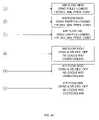
- FIGS. 4A-4Care flow charts illustrating a control of the climate control systems of FIGS. 2A & B in accordance with the chart of FIG. 3 ;
- FIG. 5is a psychometric chart showing illustrative operational modes of the climate control systems of FIGS. 2A and 2B ;
- FIG. 6is a flow chart illustrating a control of the climate control systems of FIGS. 2A and 2B according to the chart of FIG. 5 ;
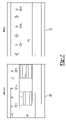
- FIG. 7shows displays of the climate control systems of FIGS. 2A and 2B ;
- FIG. 8is a schematic illustrating a plurality of climate control systems of FIG. 2A having their control modules teamed together.
- control modulerefers to an electronic device that can be configured to control other devices.
- a control modulecan include one or more of an application specific integrated circuit (ASIC), an electronic circuit, a processor (shared, dedicated or group) and memory that execute one or more software or firmware programs, a programmable control system, a process control system, a combinational logic circuit, or other suitable components that provide the described functionality.
- ASICapplication specific integrated circuit
- processorshared, dedicated or group
- memoryexecute one or more software or firmware programs
- programmable control systemprogrammable control system
- process control systema combinational logic circuit, or other suitable components that provide the described functionality.
- a plurality of air supply sources or cooling technologiesmay be utilized to provide an appropriate environment for the operation of a data center.
- the temperature (dry-bulb and dew point) of the supply airis optimized by the use of outside air. It may be desired to maintain a particular dry bulb (db) temperature range which may be selected by the user.
- cooling systems or sourcescan be combined and controlled using a control module.
- such cooling systems or sourcesinclude outdoor air, variable capacity compressors, chilled water, variable speed motors, electronic expansion valves, air economizers and fluid economizers.
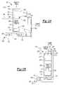
- FIGS. 2A and 2Bdepict climate control systems 201 ( FIG. 2A ), 202 ( FIG. 2B ) for a data center 200 that combines an air economizer 204 with a cooling unit, such as a CRAC 116 .
- Air economizer 204provides for the use of outside air in cooling data center 100 under appropriate conditions, as described below.
- climate control systems 201 , 202output supply air to the data center. This air may or may not be temperature and humidity conditioned depending on the use of air economizer 204 as described below.
- Each such climate control system 201 , 202may include a control module 206 capable of controlling the climate control system related equipment.
- Supply air sensor 208senses the temperature and in an aspect, may also sense the humidity of the supply air that the climate control systems 201 , 204 output into the data center 200 .
- Supply air sensor 208may illustratively be located in plenum 114 under raised floor 110 of the data center 100 (where the climate control system supplies the supply air into plenum 114 , in an outlet duct, or in a cold aisle.
- An air return from the data centermay be provided at a return air damper 210 of an air economizer plenum 212 of air economizer 204 of the climate control system 201 , 202 .
- the air economizer plenum 212 , associated control module and sensorscan be retrofitted to an existing climate control system having a cooling unit, or can be incorporated with a cooling unit in a climate control system.
- the control of climate control system 201 , 202 having CRACs 116 with air economizers 204may illustratively be provided by control module 206 .
- Return air damper 210may be mechanically or electrically controlled by control module 206 to selectively allow air that has circulated through the data center to enter the air economizer plenum 212 to provide air to CRAC 116 of the climate control system 201 , 202 .
- return air damper 210may illustratively be a motorized damper.
- Return air damper 210may be selectively opened or closed, or preferably regulated to a desired position ranging from full open to full closed as described in more detail below.
- Return air sensor 214may be located at or near return air damper 210 to sense the temperature and humidity of the return air at return air damper 210 .
- the air economizer plenum 212may also include an outside air damper 216 that selectively allows outdoor air to enter the air economizer plenum 212 of the climate control system 201 , 202 from an outside air inlet 222 coupled to outside air damper 216 by a duct 224 .
- a filter 226may provided in duct 224 .
- Outside air damper 216may be mechanically or electrically controlled by control module 206 to selectively allow outdoor air to enter the air economizer plenum 212 .
- return air damper 210may illustratively be a motorized damper.
- Outside air damper 216may be selectively opened or closed, or preferably regulated to a desired position ranging from full open to full closed, as described in more detail below.
- Outside air sensor 218may be located at outside air damper 216 to sense the temperature and humidity of the outside air at or near outside air damper 216 .
- Outside air damper 216may be fitted with guards or other fixtures (not shown) to prevent the entry of physical items from outdoors into the air economizer plenum 212 .
- sensors 208 , 214 , 218are any type of sensor that sense dry bulb temperature and a parameter indicative of humidity, such as humidity or wet bulb temperature as appropriate. Each sensor may be a combined sensor that senses both dry bulb temperature and the parameter indicative of humidity, or may include separate sensors, one that senses dry bulb temperature and one that senses the parameter indicative of humidity.
- supply air sensor 208may be a thermistor (such as where sensor 208 does not sense the parameter indicative of humidity).
- Supply air sensor 208may illustratively be a sensor having part number 148039P1
- return air sensor 214may illustratively be a sensor having part number 181464G1
- outside air sensor 218may illustratively be a sensor having part number 181465G1, each available from Liebert Corporation of Columbus, Ohio.
- the air economizer plenum 212illustratively provides a source of air for CRAC 116 of the climate control system 201 , 202 .
- a filter 220may be included between the air economizer plenum 212 and CRAC 116 .
- the air provided to the air economizer plenummay be controlled by regulating the positions of return air damper 210 and outside air damper 216 , which may be controlled by outputs of the control module 206 .
- the positions of return air damper 210 and outside air damper 216may be controlled based on temperature and humidity readings from sensors 208 , 210 and 216 , which in turn may be provided to the control module 206 .
- the positions of return air damper 210 and outside air damper 216may be controlled by control module 206 based on an emergency condition wherein CRAC 116 fails to operate properly. In this emergency mode, it may be desired to open outside air damper 216 as long as the outdoor dry bulb temperature (sensed by outside air sensor 218 ) is less than the return air dry bulb temperature (sensed by return air sensor 214 ).
- CRAC 116includes a variable compressor.
- CRAC 116includes a capacity modulated compressor type of compressor or a 4-step semi-hermetic compressor, such as those available from Emerson Climate Technologies or Liebert Corporation.
- climate control systems 202 , 202may also include one or more air moving units 119 , such as fans or blowers.
- the air moving units 119may be provided in CRACs 116 or may additionally or alternatively be provided in supply air plenum 114 as shown in phantom at 121 .
- Air moving units 119 , 121may illustratively have variable speed drives, shown at 228 for air moving unit 119 .
- CRAC 116may include a fluid economizer 230 shown in phantom in FIG. 2A .
- Fluid economizer 230includes a fluid cooling coil 232 disposed in CRAC 116 coupled to a dry cooler 234 .
- Control of a data center cooling systemrequires modification when including an air economizer compared to a data center cooling system that does not utilize an air economizer.
- the key element of operation with an air economizeris an expected significant savings in power based on reduced operation of compressors for compressor or chilled fluid cooling and motors for air movement.
- the control of the data center cooling system having an air economizermust stage the appropriate system components, e.g., compressors and/or valves, air movers, the air economizer, fluid economizer (if present), etc, to provide effective cooling while protecting critical computing loads and the air conditioning unit(s) itself.
- the outdoor ambient airprovides the basic function to drive unit control settings for rejecting heat either via air or fluid cooled heat exchangers. It also is used to indicate the potential for direct application of outdoor air for cooling by the air economizer. Additionally, the conditioning load and status of each cooling unit of the data center (either assigned for conditioning or standby modes of operation within a group) are used to select operating levels of air moving and primary cooling devices.
- the outdoor ambient air conditions of temperature and moisture contentare measured to evaluate the suitability of direct use of the outside ambient air for cooling. These conditions may be tracked over time to estimate recurring patterns in a Fuzzy logic mode.
- the program logicis adjusted to recognize the loss of humidity control whenever dampers of the air economizer are open to the outdoor environment.
- the basic moisture content of the outdoor ambient airwill overpower the data center air conditioning system and set the moisture levels inside the data center. This operation is fundamentally different from the general approach in data center cooling discussed above of maintaining a relatively narrow desired humidity range while operating within a vapor barrier with less than 5% infiltration.
- each variable energy consuming devicee.g., compressors, chilled water valves and air moving devices. These devices may be multiple per unit and the site may have multiple units serving the total load. Therefore, a basic assessment of the total heat load requirement of the data center must be made to effectively set the cooling level of each device used in the cooling of the data center. Direct measurements of data center power consumption may be an input to the control, or monitoring the cooling output within the unit control may be used to determine this heat load. As the heat load is determined, hierarchical decisions for airflow, number of compressors, operating points for variable mass flow compressors and valve positions for variable temperature cooling fluids can be made. These decisions are dynamic to adjust for changes within the load profile.
- each variable energy consuming devicee.g., compressors, chilled water valves and air moving devices.
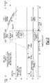
- FIG. 3is a chart illustrating the operation of the above described data center climate control systems 201 , 204 at various outdoor ambient air (OA) conditions at various data center heat loads, including variable speed drive considerations of the air mover(s) of climate control systems 201 , 202 and capacity modulated compressor type of compressor considerations and/or capacity modulated chilled water (“CW”) valve considerations.
- OAoutdoor ambient air
- CWcapacity modulated chilled water
- High heat load/high OAairflow high/CRAC (compressors or CW valves of CRAC) fully loaded/air economizer closed/heat rejection device fully loaded (as shown by branch A in FIGS. 4A & B).
- Moderate heat load/high OAairflow moderate/CRAC partly loaded/air economizer closed/heat rejection device partly loaded (as shown by branch B in FIGS. 4A & B).
- High heat load/moderate OAairflow high/CRAC fully loaded/air economizer closed/heat rejection device partly loaded (as shown by branch D in FIGS. 4A & B); or, if outdoor air is suitable for partial cooling (outdoor enthalpy lower than indoor enthalpy or outdoor humidity acceptable), airflow high/CRAC modulating with air economizer/heat rejection device partly loaded (as shown by branch G—Partial in FIGS. 4A & B); or, if outdoor air is suitable for full cooling, airflow high/CRAC off/air economizer provides all cooling/heat rejection device off; (as shown by branch G'Full in FIGS. 4A & B).
- Moderate heat load/moderate OAairflow moderate/CRAC partly loaded/air economizer closed/heat rejection device partly loaded (as shown by branch E in FIGS. 4A & B); or, if outdoor air is suitable for partial cooling, airflow moderate/CRAC modulating with air economizer/heat rejection device partly loaded (as shown by branch H—Partial in FIGS. 4A & B); or, if outdoor air is suitable for full cooling, airflow moderate/CRAC off/air economizer provides all cooling/heat rejection device off; (as shown by branch H—Full in FIGS. 4A & B).
- Low heat load/moderate OAairflow minimal/CRAC lightly loaded/air economizer closed/heat rejection device lightly loaded (as shown by branch F in FIGS. 4A & B); or, if outdoor air is suitable for cooling, airflow minimal/CRAC off/air economizer provides all cooling/heat rejection device off; (as shown by branch I in FIGS. 4A & B).
- Low heat load/low OAairflow minimal/CRAC lightly loaded/air economizer closed/heat rejection device in minimum pressure control (as shown by branch L in FIGS. 4A & C); or, if outdoor air is suitable for cooling, airflow minimal/CRAC off/air economizer provides all cooling without overcooling/heat rejection device off (as shown by branch O in FIGS. 4A & C).
- Load estimations for the variable speed drive of air moving unit 119 , 121may be as follows:
- the data center control moduleapplies a variety of safety operations to prevent overcooling the data center heat loads (for example, the electronic equipment in equipment racks in the data center) or allowing the climate control system to operate outside of preset boundaries.
- the use of the air economizermay be over-ridden for a variety of user reasons. Therefore, an accessible switch is available to prevent air economizer operation when issues such as air contaminants become unacceptable or secondary equipment is not functional.
- control module 206 of the climate control systems 201 , 202An important aspect of the control implemented in control module 206 of the climate control systems 201 , 202 is the capability to allow the user to make compromise decisions between energy savings and projected life of the electronic equipment that operates within the operation of the data center climate control system. Operation with an air economizer offers a significant energy savings, but it is subject to the ambient humidity levels. Frequent swings in humidity may reduce the useful life of some electronic devices. As those levels of life vs. humidity swings and cost of electricity are evaluated by data center operators, adjustments can be applied to the control to limit or expand the air economizer function.
- Airflowis the rate of flow of the supply air moved by the air movers (such as fans) of the data center climate control system to introduce the supply air into the data center.
- High, moderate and low ambient outside airmay be preset parameters or may be user settable parameters.
- high ambient outdoor airis when the dry bulb temperature of the ambient outside air is 90 degrees Fahrenheit or above
- moderate ambient outdoor airis when the dry bulb temperature of the outdoor ambient air is the range of 50 to 70 degrees Fahrenheit
- low outdoor ambient airis when the dry bulb temperature of the outdoor ambient air is 40 degrees Fahrenheit or less.
- control module 206includes fluid economizer 230 in the staging of the various cooling devices.
- control module 206stages the cooling devices in the order of air economizer 204 (assuming outside ambient air is suitable for use), fluid economizer 230 and the compressor/CW valves. That is, if outside ambient air is suitable for cooling the data center and is adequate to provide all the cooling, then only air economizer 204 is used to cool the data center. If the outside air is not adequate to provide all the cooling, then the fluid economizer 230 is added to the mix, with by way of example and not of limitation, the use of outside air maximized and the use of fluid economizer minimized.
- the compressors/CW valves of CRAC 116are added to the mix, with by way of example and not of limitation, the use of outside air maximized, the use of fluid economizer 230 maximized to the extent needed to supplement the outside air, and the use of use of the compressors/CW valves of CRAC 116 minimized.
- the control module 206 of data center climate control system 201 , 206may compare the measured values to predetermined or adjustable setpoints.
- P 4parameter to adjust the alarm sensitivity of alarm 2 , discussed in more detail below.
- P 5parameter to adjust the alarm sensitivity of alarm 3 , discussed in more detail below.
- FCthe percentage of cooling provided by outdoor air, i.e., “free cooling.”
- variables or set pointscan be preset. They can also be user programmable so that the control is adaptive and allows for changing the way in which the climate control system is controlled over the life of the data center.
- FIG. 5is a psychometric chart including various modes that may be employed based on the climate control system operating conditions and measured parameters.
- FIG. 6is a flow chart showing four example control modes for the climate control systems 201 , 202 .
- the control modesmay illustratively be implemented by control module 206 programmed with software to execute the control modes.
- control module 206determines that the dew point of the outside ambient air at sensor 218 (dp OA) ⁇ P 2 , then control module 206 is in Mode Y at 602 where it has outside air damper 216 fully closed. Using the parameters provided above, this means that Mode Y is utilized when the dew point temperature at outside air sensor 218 is less than the dew point temperature set point P 2 . In mode Y, outside air damper 216 is closed. All of the cooling is provided by CRAC(s) 216 of the climate control systems 201 , 202 and the free cooling is at 0%. As used herein, “free cooling” means the cooling from the outside ambient air obtained via air economizer 204 .
- Humidifier control functionsmay also be performed in Mode Y. However, if the climate control system 201 , 202 would otherwise be in Mode Y and an emergency mode condition is encountered, the outside air damper 216 may be opened to allow outdoor air to assist in cooling the data center 200 , as shown in phantom at 604 .
- control module 206determines that the dew point of the outside air (dp OA)>P 3 , then control module 206 is in Mode Z at 608 where it has outside air damper 216 fully closed and free cooling is at 0%: In this case, the dew point temperature of the outside ambient air is greater than the maximum dew point setpoint, and outside ambient air is not used to cool the data center 200 .
- control module 206is in Mode X at 612 where outside air damper 216 of air economizer 204 is open and the outside air provided by air economizer 204 provides the principal source of cooling air to data center 200 .
- CRACs 116only provide cooling as needed to assist the outdoor air.
- the dry bulb temperature of the outside ambient airis less than the room return air dry bulb temperature and the dry bulb temperature set point.
- the return air damper 210 and the outside air damper 216are regulated to obtain the appropriate mix of room return air and outdoor air.
- the free coolingmay be up to 100% depending on whether db OA is low enough to satisfy the full cooling load of data center 200 .
- CRACs 116are illustratively used to assist with cooling the data center 200 such that FC ⁇ 100%.
- control module 206determines that the dry bulb temperature of the outside ambient air (db OA) is less than the dry bulb temperature of the room return air at return air sensor 214 (db RA) and db OA>P 1 , control module 206 is in Mode W at 616 where CRACs 116 of climate control systems 202 , 204 operate to provide cooling air and outside air damper 216 is also opened.
- FC100% ⁇ A %, where A % is the % operation of CRACs 116 .
- the dry bulb temperature the outside ambient airis less than the dry bulb temperature of the room return air, but greater than the dry bulb temperature set point.
- Outdoor airis used in conjunction with CRACs 116 unit to provide supply air at the requisite temperature to cool the data center 200 , and the free cooling percentage is based on the percent usage of the cooling unit capacity. (For example, if the cooling unit has a capacity modulated compressor and the capacity modulated compressor is on 60%, the free cooling is 40%. If the cooling unit uses cooling water and the cooling water (CW) valve is 60% open, the free cooling is 40%.)
- the climate control systems 202 , 202may also have a user-selectable lockout mode. During lockout mode, the outside air damper 216 of the air economizer 204 is closed and the CRACs provide all of the cooling.
- control module 206operates CRACs 116 to control humidity of data center 200 only during Mode Y.
- the speed of the blower/fan of air moving unit 119 , 121may be controlled as follows in certain of the above modes, such as by setting the appropriate frequency of variable speed drive 228 .
- blower/fan speedis set equal to the percent usage of CRAC(s) 116 (minimum of 60%). For example if the capacity modulation is 70% (for a CRAC having a capacity modulated compressor) or the CW valve is 70% open (for a CRAC having a CW), then the blower/fan speed is set equal to 70%.
- control module 206begins operating the variable frequency drive at 2 Hz above the frequency at which it operated variable frequency drive 702 in the last Mode Y or Mode Z operation. If the dry bulb temperature of the room return air (db RA) increases by more than a predetermined amount, such as 5° F., from the last reading when in the Mode Y or Mode Z operation, control module 206 returns to the air economizer lock out mode where air economizer 204 is closed for a predetermined time period, such as fifteen minutes. (Top speed is retained as the default 50 or 60 Hz of the variable frequency drive).
- a predetermined amountsuch as 5° F.
- control module 206may utilize sensor inputs and setpoints to diagnose alarm conditions and activate alarms.
- the alarmsmay be activated, by way of example and not of limitation, by displaying alarm information on display 700 or 702 ( FIG. 7 ).
- the alarmsmay also include audible and/or visual alarms.
- outside air damper 216may be closed and an alarm activated that the “outside air damper 216 is not operating effectively.”
- the dry bulb temperature of the outside ambient air (db OA)appears to be lower than the setpoint temperature P 1 , but the room return air is unable to bring the data center temperature to the setpoint P 1 . This indicates that the cooler outside air is not being transferred to the data center 200 properly.
- Mode Y or Z control module 206determines that the dew point of the outside air (dp OA) is not equal to the dew point of the supply air (dp SA) ⁇ P 4 , it activates an alarm that indicates that outside air damper 216 is not working effectively.” In this case, it is likely that the outside air is contributing to the temperature provided by the climate control system 202 , 204 diverging from the temperature at the return air damper 210 by more than then threshold P 4 .
- control module 206determines that the dry bulb temperature of the supply air (db SA) is not equal to the dry bulb set point P 1 ⁇ P 4 , control module 206 activates an alarm that indicates that the return air damper 210 is not operating effectively. In this case the temperature of the supply air is not within a predetermined threshold P 4 of the desired setpoint temperature P 1 . This provides a good indication that the return air damper 210 is not operating properly.
- the climate control systemmay also be provided with a display as depicted in FIG. 7 .
- the return air and supply air dry bulb temperatures(db R, db SA) may be displayed.
- Relative humiditymay also be calculated and displayed.
- the actual number to be displayedis the relative humidity percentage at the average temperature of db RA and db OA when the dew-point is the average of db RA and db OA.
- Free coolingmay also be displayed such as by a numeric display.
- the climate control systems 201 , 202may also be operated with a plurality of systems 201 , 202 providing climate control to a single data center room or location.
- a plurality of systems 201may operate in a “teamwork” mode. (It should be understood that the plurality of systems can alternatively have systems 202 or additionally have systems 202 .)
- Individual temperature and humidity readings from the respective sensors at each system 201may not be exactly the same. Absent some sort of teamwork, these divergent conditions might cause the respective systems 201 to operate against each other. This may use more energy and further exacerbate any temperature or humidity differences as sensed by any one unit.
- each set of the respective supply air sensors 208 1 - 208 N of plurality of systems 201 , outdoor ambient air sensors 218 1 - 218 N , and return air sensors 214 1 - 214 Nmay have their values averaged to determine average values SA AVG , OA AVG , and RA AVG .
- the individual climate control systems 201may then operate based on the average values. Teamwork may also be used when an emergency mode occurs to assist in supplying the cooling function that would normally be provided by the system operating in emergency mode.
- each control module 206operates its respective climate control system 201 based in part on how the other climate control systems 201 are operating. For example, if one of the climate control systems 201 is using outside air to cool data center 200 , then the control modules for all the climate control systems 201 may shut off humidity control.
- first, second, third, etc.may be used herein to describe various elements, components, regions, layers and/or sections, these elements, components, regions, layers and/or sections should not be limited by these terms. These terms may be only used to distinguish one element, component, region, layer or section from another region, layer or section. Terms such as “first,” “second,” and other numerical terms when used herein do not imply a sequence or order unless clearly indicated by the context. Thus, a first element, component, region, layer or section discussed below could be termed a second element, component, region, layer or section without departing from the teachings of the example embodiments.
- Spatially relative termssuch as “inner,” “outer,” “beneath”, “below”, “lower”, “above”, “upper” and the like, may be used herein for ease of description to describe one element or feature's relationship to another element(s) or feature(s) as illustrated in the figures. Spatially relative terms may be intended to encompass different orientations of the device in use or operation in addition to the orientation depicted in the figures. For example, if the device in the figures is turned over, elements described as “below” or “beneath” other elements or features would then be oriented “above” the other elements or features. Thus, the example term “below” can encompass both an orientation of above and below. The device may be otherwise oriented (rotated 90 degrees or at other orientations) and the spatially relative descriptors used herein interpreted accordingly.
Landscapes
- Engineering & Computer Science (AREA)
- General Engineering & Computer Science (AREA)
- Chemical & Material Sciences (AREA)
- Combustion & Propulsion (AREA)
- Mechanical Engineering (AREA)
- Physics & Mathematics (AREA)
- Fluid Mechanics (AREA)
- Signal Processing (AREA)
- Fuzzy Systems (AREA)
- Mathematical Physics (AREA)
- Computer Hardware Design (AREA)
- Thermal Sciences (AREA)
- Microelectronics & Electronic Packaging (AREA)
- Air Conditioning Control Device (AREA)
Abstract
Description
- Capacity (load)=1.08×CFM×ΔT between OA and RA OA & Return Air (RA) CFM=f(damper positions)
- Tmixed air=TRA(% damper)+TOA(% damper) (where TRAis the temperature of the return air and TOAis the temperature of the outside air)
- Capacity (load)=Dig. % (unit rating) (where Dig. % (unit rating) is the on % of the compressor)
- Also or alternatively, the penetration of the proportional band is monitored for cooling requirements and also used to determine the load requirement.
- Capacity (load)=(Dampers+Compressor %) unit rating
Claims (28)
Priority Applications (1)
| Application Number | Priority Date | Filing Date | Title |
|---|---|---|---|
| US12/371,641US8583289B2 (en) | 2008-02-19 | 2009-02-16 | Climate control system for data centers |
Applications Claiming Priority (2)
| Application Number | Priority Date | Filing Date | Title |
|---|---|---|---|
| US6631108P | 2008-02-19 | 2008-02-19 | |
| US12/371,641US8583289B2 (en) | 2008-02-19 | 2009-02-16 | Climate control system for data centers |
Publications (2)
| Publication Number | Publication Date |
|---|---|
| US20090210096A1 US20090210096A1 (en) | 2009-08-20 |
| US8583289B2true US8583289B2 (en) | 2013-11-12 |
Family
ID=40955849
Family Applications (1)
| Application Number | Title | Priority Date | Filing Date |
|---|---|---|---|
| US12/371,641Active2031-10-14US8583289B2 (en) | 2008-02-19 | 2009-02-16 | Climate control system for data centers |
Country Status (1)
| Country | Link |
|---|---|
| US (1) | US8583289B2 (en) |
Cited By (21)
| Publication number | Priority date | Publication date | Assignee | Title |
|---|---|---|---|---|
| US20110303406A1 (en)* | 2010-06-11 | 2011-12-15 | Fujitsu Limited | Air-conditioning system and control device thereof |
| US20120037233A1 (en)* | 2009-04-27 | 2012-02-16 | Renee Seeliger | Direct free cooling |
| US20130019747A1 (en)* | 2010-03-31 | 2013-01-24 | Stuart Martin Innes | Super Integrated Security and Air Cleansing Systems (SISACS) |
| US8721409B1 (en)* | 2007-07-31 | 2014-05-13 | Amazon Technologies, Inc. | Airflow control system with external air control |
| US8918218B2 (en) | 2010-04-21 | 2014-12-23 | Honeywell International Inc. | Demand control ventilation system with remote monitoring |
| US20150011153A1 (en)* | 2012-02-10 | 2015-01-08 | Josef Oswald | Ventilation device for clean room applications |
| US9255720B2 (en) | 2010-04-21 | 2016-02-09 | Honeywell International Inc. | Demand control ventilation system with commissioning and checkout sequence control |
| US9500382B2 (en) | 2010-04-21 | 2016-11-22 | Honeywell International Inc. | Automatic calibration of a demand control ventilation system |
| US9703299B2 (en) | 2010-09-24 | 2017-07-11 | Honeywell International Inc. | Economizer controller plug and play system recognition with automatic user interface population |
| US20170299209A1 (en)* | 2016-04-14 | 2017-10-19 | Schneider Electric It Corporation | Systems and methods for minimizing compressor use in hvac systems |
| US9832911B2 (en) | 2014-10-09 | 2017-11-28 | Airedale International Air Conditioning Ltd. | Air handling unit and method of operating the same |
| US9845963B2 (en) | 2014-10-31 | 2017-12-19 | Honeywell International Inc. | Economizer having damper modulation |
| US9886042B2 (en) | 2015-04-27 | 2018-02-06 | International Business Machines Corporation | Localized computer system humidity control |
| US10060642B2 (en) | 2014-10-22 | 2018-08-28 | Honeywell International Inc. | Damper fault detection |
| US10502470B2 (en) | 2016-03-22 | 2019-12-10 | Vertiv Corporation | System and method to maintain evaporator superheat during pumped refrigerant economizer operation |
| WO2020082666A1 (en)* | 2018-10-24 | 2020-04-30 | 青岛海尔空调器有限总公司 | Smart home system |
| US10653042B2 (en) | 2016-11-11 | 2020-05-12 | Stulz Air Technology Systems, Inc. | Dual mass cooling precision system |
| US10869410B1 (en) | 2019-06-27 | 2020-12-15 | Munters Corporation | Air handling unit with indirect air-side economizer and decoupled variable speed scavenger and condenser fan control |
| US11076509B2 (en) | 2017-01-24 | 2021-07-27 | The Research Foundation for the State University | Control systems and prediction methods for it cooling performance in containment |
| US11406046B2 (en)* | 2020-01-13 | 2022-08-02 | Dell Products, L.P. | Data center cooling system that prevents condensation caused by opening external access doors |
| US11408621B2 (en) | 2020-12-15 | 2022-08-09 | Trane International Inc. | Systems and methods for controlling free cooling and integrated free cooling |
Families Citing this family (91)
| Publication number | Priority date | Publication date | Assignee | Title |
|---|---|---|---|---|
| US7430118B1 (en) | 2007-06-04 | 2008-09-30 | Yahoo! Inc. | Cold row encapsulation for server farm cooling system |
| JP4724730B2 (en)* | 2008-04-09 | 2011-07-13 | 株式会社日立製作所 | Information processing system operation management method, operation management program, operation management apparatus, and information processing system |
| GB2464354B (en)* | 2009-03-13 | 2011-06-08 | 4Energy Ltd | Equipment enclosure |
| US8054625B2 (en) | 2009-04-21 | 2011-11-08 | Yahoo! Inc. | Cold row encapsulation for server farm cooling system |
| US10212858B2 (en) | 2009-04-21 | 2019-02-19 | Excalibur Ip, Llc | Cold row encapsulation for server farm cooling system |
| GB2467808B (en) | 2009-06-03 | 2011-01-12 | Moduleco Ltd | Data centre |
| US9101080B2 (en) | 2009-09-28 | 2015-08-04 | Amazon Technologies, Inc. | Modular computing system for a data center |
| BE1019118A5 (en) | 2009-12-21 | 2012-03-06 | Cofely Services | UNIT, METHOD AND SYSTEM FOR TREATING AIR. |
| FR2954670B1 (en) | 2009-12-22 | 2017-06-09 | Atrium Data | METHOD AND DEVICE FOR REDUCING THE ENERGY CONSUMPTION OF A CENTER COMPRISING ENERGY EQUIPMENT. |
| FR2954671B1 (en) | 2009-12-22 | 2012-01-27 | Atrium Data | METHOD AND DEVICE FOR REDUCING THE ENERGY CONSUMPTION OF A CENTER COMPRISING ENERGY EQUIPMENT. |
| GB2477494A (en)* | 2010-02-01 | 2011-08-10 | Hitec Air Conditioning Services Ltd | Air cooling system |
| US8782213B2 (en)* | 2010-03-01 | 2014-07-15 | Ching-I Hsu | System and method for the application of psychrometric charts to data centers |
| US20110225997A1 (en)* | 2010-03-17 | 2011-09-22 | Mechanical Service & Systems, Inc. | Systems and methods for cooling computer data centers |
| US8364318B2 (en)* | 2010-04-21 | 2013-01-29 | Honeywell International Inc. | Demand control ventilation with fan speed control |
| US8628153B2 (en) | 2010-05-13 | 2014-01-14 | Pandult Corp. | Aisle containment system |
| US8628158B2 (en) | 2010-05-13 | 2014-01-14 | Panduit Corp. | Aisle containment system |
| US8628154B2 (en) | 2010-05-13 | 2014-01-14 | Panduit Corp. | Aisle containment system |
| JP5185319B2 (en)* | 2010-05-14 | 2013-04-17 | 株式会社東芝 | Air conditioning system and air conditioning control method for server room management |
| GB201008825D0 (en)* | 2010-05-26 | 2010-07-14 | Bripco Bvba | Data centre cooling system |
| FR2960662A1 (en) | 2010-05-31 | 2011-12-02 | Atrium Data | OPTIMIZATION OF THE ENERGY PERFORMANCE OF A CENTER COMPRISING ENERGY EQUIPMENT. |
| ES2371194B1 (en)* | 2010-06-09 | 2012-09-07 | Gesab, S.A. | AIR CONDITIONING METHOD FOR COMPUTER ROOMS AND INSTALLATION TO CARRY OUT THE SAID METHOD. |
| US8532838B2 (en) | 2010-06-25 | 2013-09-10 | International Business Machines Corporation | System, method, and computer program product for controlling energy consumption in data centers |
| US20120073783A1 (en)* | 2010-09-27 | 2012-03-29 | Degree Controls, Inc. | Heat exchanger for data center |
| DE102010041440A1 (en)* | 2010-09-27 | 2012-03-29 | Siemens Aktiengesellschaft | Vehicle with a cooled by means of a cooling air mass flow component |
| RU2555229C2 (en)* | 2010-12-01 | 2015-07-10 | Инновачи Инк. | Commercial device for variable climate control |
| CN102200333B (en)* | 2010-12-08 | 2014-04-16 | 中国电信股份有限公司 | Temperature and humidity control method, intelligent energy-saving controller and air-conditioning system |
| CN102541107B (en)* | 2010-12-24 | 2016-02-17 | 赛恩倍吉科技顾问(深圳)有限公司 | Server moisture control system |
| US9021821B2 (en) | 2010-12-30 | 2015-05-05 | Munters Corporation | Ventilation device for use in systems and methods for removing heat from enclosed spaces with high internal heat generation |
| US9032742B2 (en)* | 2010-12-30 | 2015-05-19 | Munters Corporation | Methods for removing heat from enclosed spaces with high internal heat generation |
| US9055696B2 (en)* | 2010-12-30 | 2015-06-09 | Munters Corporation | Systems for removing heat from enclosed spaces with high internal heat generation |
| NL2007293C2 (en) | 2011-01-18 | 2012-07-23 | Dataxenter Ip B V | Cooling system for cooling air in a room and data centre comprising such cooling system. |
| JP5525465B2 (en)* | 2011-01-31 | 2014-06-18 | アズビル株式会社 | Air conditioner operation control apparatus and method |
| CN102175057A (en)* | 2011-03-11 | 2011-09-07 | 苏州云博信息技术有限公司 | Air conditioner remote control method and system |
| WO2012124723A1 (en)* | 2011-03-14 | 2012-09-20 | 富士電機株式会社 | Outside air utilization air-conditioning system and air-conditioner thereof |
| WO2012158653A2 (en)* | 2011-05-13 | 2012-11-22 | Ietip Llc | System and methods for cooling electronic equipment |
| ITMO20110140A1 (en)* | 2011-05-30 | 2012-12-01 | Brennercom S P A | COOLING SYSTEM FOR MACHINE CENTERS FOR DATA PROCESSING. |
| US8725300B2 (en)* | 2011-07-08 | 2014-05-13 | Aircuity, Inc. | Methods and apparatus for differential energy based airside economizer changeover |
| BR112014001410A2 (en)* | 2011-07-22 | 2017-02-21 | Munters Corp | single dosas system designed for integration with recirculating air handling systems |
| WO2013020085A2 (en) | 2011-08-03 | 2013-02-07 | Innovaci Inc. | Method for remotely managing an enviromental control and monitoring device |
| NO346234B1 (en)* | 2011-08-08 | 2022-05-02 | Halliburton Energy Services Inc | System and procedure for storage of drilling tools, automatic self-check and operational status of rig tools |
| US20130055744A1 (en)* | 2011-09-07 | 2013-03-07 | Richard H. Travers | Auxiliary ambient air refrigeration system for cooling and controlling humidity in an enclosure |
| US8229597B2 (en)* | 2011-09-27 | 2012-07-24 | Jpmorgan Chase Bank, N.A. | Heating, ventilation, and air conditioning management system and method |
| JP5848578B2 (en)* | 2011-10-25 | 2016-01-27 | 株式会社日立製作所 | Outside air cooling system and data center |
| NL2007677C2 (en)* | 2011-10-31 | 2013-05-06 | Hiensch Engineering B V | SYSTEM FOR COOLING ELECTRONIC EQUIPMENT. |
| US9338928B2 (en)* | 2011-11-10 | 2016-05-10 | International Business Machines Corporation | Optimizing free cooling of data centers through weather-based intelligent control |
| JP2013104639A (en)* | 2011-11-16 | 2013-05-30 | Toshiba Corp | Air conditioning system and air conditioning control method for server room management |
| JP5804078B2 (en)* | 2011-12-01 | 2015-11-04 | 富士通株式会社 | Information processing device |
| JP5921461B2 (en)* | 2012-03-08 | 2016-05-24 | 株式会社日立製作所 | Outside air and local cooling information processing system and its load allocation method |
| US10531597B1 (en) | 2012-06-15 | 2020-01-07 | Amazon Technologies, Inc. | Negative pressure air handling system |
| US9395974B1 (en)* | 2012-06-15 | 2016-07-19 | Amazon Technologies, Inc. | Mixed operating environment |
| US9485887B1 (en) | 2012-06-15 | 2016-11-01 | Amazon Technologies, Inc. | Data center with streamlined power and cooling |
| US10107518B2 (en)* | 2012-07-31 | 2018-10-23 | Dell Products L.P. | Combination air handler and airflow mixing module for use in a modular data center |
| US9999163B2 (en) | 2012-08-22 | 2018-06-12 | International Business Machines Corporation | High-efficiency data center cooling |
| US8833001B2 (en) | 2012-09-04 | 2014-09-16 | Amazon Technologies, Inc. | Expandable data center with movable wall |
| US9258930B2 (en) | 2012-09-04 | 2016-02-09 | Amazon Technologies, Inc. | Expandable data center with side modules |
| JP6051829B2 (en)* | 2012-12-10 | 2016-12-27 | 日本電気株式会社 | Fan control device |
| CA2803497C (en)* | 2012-12-12 | 2018-08-21 | Vert.Com, Inc. | Prefabricated vertical data center modules and method of large-scale deployment |
| US9237681B2 (en)* | 2013-01-09 | 2016-01-12 | Io Data Centers, Llc | Modular data center |
| US9661788B2 (en) | 2013-01-09 | 2017-05-23 | Baselayer Technology, Llc | Modular data center |
| US9198310B2 (en) | 2013-03-11 | 2015-11-24 | Amazon Technologies, Inc. | Stall containment of rack in a data center |
| US9247659B1 (en)* | 2013-06-21 | 2016-01-26 | Amazon Technologies, Inc. | Slab-based cooling |
| EP2821720B1 (en)* | 2013-07-05 | 2019-05-22 | EvoSwitch IP B.V. | Arrangement for providing air to a room |
| US9615489B2 (en)* | 2013-07-05 | 2017-04-04 | Evoswitch Ip B.V. | Arrangement for providing air to a room |
| TWI499171B (en)* | 2013-08-09 | 2015-09-01 | Delta Electronics Inc | Method of air flow field control |
| US20150073606A1 (en)* | 2013-09-10 | 2015-03-12 | Microsoft Corporation | Cooling system management for server facility |
| JP5670529B1 (en)* | 2013-09-10 | 2015-02-18 | 新日鉄住金エンジニアリング株式会社 | Server rack indoor system |
| CN105705879A (en)* | 2013-09-26 | 2016-06-22 | 慧与发展有限责任合伙企业 | Controlling usage of resources based on operating status and communications |
| TW201521560A (en)* | 2013-11-22 | 2015-06-01 | Hon Hai Prec Ind Co Ltd | Container data center and heat dissipating system |
| GB2522269A (en)* | 2014-01-21 | 2015-07-22 | Ibm | Variable air cooling system for data centers |
| JP6314533B2 (en)* | 2014-02-25 | 2018-04-25 | 富士通株式会社 | Data center |
| CN106461278B (en)* | 2014-04-16 | 2020-03-06 | 江森自控科技公司 | How to run a cooler |
| US9661778B1 (en)* | 2014-06-27 | 2017-05-23 | Amazon Technologies, Inc. | Deployable barrier for data center |
| US9869982B1 (en)* | 2014-10-17 | 2018-01-16 | Google Inc. | Data center scale utility pool and control platform |
| WO2016178290A1 (en)* | 2015-05-07 | 2016-11-10 | 三菱電機株式会社 | Air conditioning system |
| US10010014B1 (en)* | 2015-06-22 | 2018-06-26 | Amazon Technologies, Inc. | Interconnecting cooling units |
| US10356956B1 (en) | 2015-06-22 | 2019-07-16 | Amazon Technologies, Inc. | Datacenter cooling unit with subfloor components |
| US10342166B2 (en)* | 2015-10-21 | 2019-07-02 | Vertiv Corporation | Cooling systems for small equipment rooms and methods of cooling small equipment rooms |
| US9901011B2 (en)* | 2015-11-04 | 2018-02-20 | Rite-Hite Holding Corporation | Cooling systems for devices arranged in rows |
| KR102599450B1 (en) | 2016-03-16 | 2023-11-09 | 이너테크 아이피 엘엘씨 | Systems and methods for performing series heat dissipation and coordinated cooling using fluid coolers and chillers |
| US10705580B2 (en)* | 2016-08-25 | 2020-07-07 | Oracle International Corporation | Intelligent energy-optimization technique for computer datacenters |
| US10251312B2 (en) | 2016-09-09 | 2019-04-02 | Rite-Hite Holding Corporation | Cooling systems for devices arranged in rows |
| EP3559561B1 (en)* | 2016-11-09 | 2024-01-31 | Moore, Kevin Daniel Martin | Methods for reducing energy consumption in a heating, ventilation and air conditioning (hvac) system |
| US9888615B1 (en) | 2016-12-22 | 2018-02-06 | Amazon Technologies, Inc. | Tape library rack module with environmentally isolated interior |
| US10921012B1 (en)* | 2017-03-06 | 2021-02-16 | EnTouch Controls Inc. | System and method for compressor optimization and system cycling using ambient air for cooling or heating |
| US10897836B2 (en)* | 2018-04-30 | 2021-01-19 | Baidu Usa Llc | Airflow management system for thermal control of data centers |
| CA3241415A1 (en) | 2018-10-02 | 2020-04-09 | Rite-Hite Holding Corporation | Air barrier systems for data center zone containment |
| US11006551B2 (en)* | 2019-08-30 | 2021-05-11 | Dell Products, L.P. | Method for re-direction of airflow from air handler system(s) integrated into a modular data center |
| US11523546B1 (en)* | 2019-10-11 | 2022-12-06 | Meta Platforms, Inc. | Rack-level aisle emulator |
| CN215001992U (en)* | 2021-01-27 | 2021-12-03 | 华为数字能源技术有限公司 | Air wall system and data center |
| CN113301785A (en)* | 2021-06-29 | 2021-08-24 | 厦门科灿信息技术有限公司 | Dynamic control method and device of data center air conditioner, terminal and storage medium |
| CN114110979B (en)* | 2021-11-25 | 2023-02-28 | 珠海格力电器股份有限公司 | Air conditioner and control method |
Citations (31)
| Publication number | Priority date | Publication date | Assignee | Title |
|---|---|---|---|---|
| US3949808A (en) | 1975-01-22 | 1976-04-13 | Lennox Industries, Inc. | Air conditioning apparatus |
| US3979922A (en) | 1974-12-30 | 1976-09-14 | Honeywell Inc. | Energy conservation air conditioning system |
| US3982583A (en) | 1974-12-30 | 1976-09-28 | Honeywell Inc. | Optimized air conditioning system |
| US4044947A (en) | 1976-06-01 | 1977-08-30 | Honeywell Inc. | Condition and volume control for air conditioning system mixing dampers |
| US4086781A (en) | 1976-04-23 | 1978-05-02 | International Telephone & Telegraph Corporation | Variable air volume air conditioning system |
| US4199101A (en) | 1979-01-26 | 1980-04-22 | Johnson Controls, Inc. | Multiple load integrated fluid control units |
| US4210278A (en) | 1979-02-06 | 1980-07-01 | The United States Of America As Represented By The Administrator Of The National Aeronautics And Space Administration | Apparatus for supplying conditioned air at a substantially constant temperature and humidity |
| US4293027A (en) | 1977-10-25 | 1981-10-06 | Energetics Systems Corp. | Control system for heating and cooling units |
| US4347712A (en) | 1980-11-03 | 1982-09-07 | Honeywell Inc. | Microprocessor discharge temperature air controller for multi-stage heating and/or cooling apparatus and outdoor air usage controller |
| US4362026A (en) | 1980-10-27 | 1982-12-07 | Miller Lloyd W | Enthalpy control |
| US4437608A (en) | 1982-05-17 | 1984-03-20 | Smith Robert B | Variable air volume building ventilation system |
| US4485632A (en) | 1983-04-20 | 1984-12-04 | Loew's Theatres, Inc. | Control circuit for air conditioning systems |
| US4495986A (en) | 1982-06-21 | 1985-01-29 | Carrier Corporation | Method of operating a variable volume multizone air conditioning unit |
| US4506514A (en) | 1984-04-30 | 1985-03-26 | The Bahnson Company | Controlling energy in an air-conditioning system |
| US4841733A (en) | 1988-01-07 | 1989-06-27 | Dussault David R | Dri-Pc humidity and temperature controller |
| US5279609A (en) | 1992-10-30 | 1994-01-18 | Milton Meckler | Air quality-temperature controlled central conditioner and multi-zone conditioning |
| US5544697A (en) | 1983-09-02 | 1996-08-13 | Carrier Corporation | Differential temperature control |
| US5597354A (en) | 1995-06-13 | 1997-01-28 | Johnson Service Company | Indoor air quality control for constant volume heating, ventilating and air conditioning units |
| US5769314A (en) | 1996-03-20 | 1998-06-23 | Johnson Service Company | Variable air volume HVAC system controller and method |
| US5791408A (en) | 1996-02-12 | 1998-08-11 | Johnson Service Company | Air handling unit including control system that prevents outside air from entering the unit through an exhaust air damper |
| US6161764A (en) | 1999-01-22 | 2000-12-19 | Honeywell International Inc. | Enhanced economizer controller |
| US6176436B1 (en) | 1997-09-19 | 2001-01-23 | Pentech Energy Solutions, Inc. | Method and apparatus for energy recovery in an environmental control system |
| US6318096B1 (en) | 2000-09-05 | 2001-11-20 | The University Of Akron | Single sensor mixing box and methodology for preventing air handling unit coil freeze-up |
| US6415617B1 (en) | 2001-01-10 | 2002-07-09 | Johnson Controls Technology Company | Model based economizer control of an air handling unit |
| US6481635B2 (en) | 2000-07-21 | 2002-11-19 | Gun Valley Temperature Controls Llc | Environmental control method |
| US6634422B2 (en) | 1999-06-22 | 2003-10-21 | York International Corporation | Method for controlling an economizer |
| US6749125B1 (en) | 2002-03-08 | 2004-06-15 | Jonathan Carson | Central air conditioning, cooling and whole-house ventilation system |
| US20050225936A1 (en)* | 2002-03-28 | 2005-10-13 | Tony Day | Cooling of a data centre |
| US20060150644A1 (en)* | 2005-01-10 | 2006-07-13 | Wruck Richard A | Indoor air quality and economizer control methods and controllers |
| US20060234621A1 (en)* | 2005-03-10 | 2006-10-19 | Desrochers Eric M | Multipoint air sampling system having common sensors to provide blended air quality parameter information for monitoring and building control |
| US20080185446A1 (en)* | 2007-02-07 | 2008-08-07 | Tozer Robert M | Cool design data center |
- 2009
- 2009-02-16USUS12/371,641patent/US8583289B2/enactiveActive
Patent Citations (31)
| Publication number | Priority date | Publication date | Assignee | Title |
|---|---|---|---|---|
| US3979922A (en) | 1974-12-30 | 1976-09-14 | Honeywell Inc. | Energy conservation air conditioning system |
| US3982583A (en) | 1974-12-30 | 1976-09-28 | Honeywell Inc. | Optimized air conditioning system |
| US3949808A (en) | 1975-01-22 | 1976-04-13 | Lennox Industries, Inc. | Air conditioning apparatus |
| US4086781A (en) | 1976-04-23 | 1978-05-02 | International Telephone & Telegraph Corporation | Variable air volume air conditioning system |
| US4044947A (en) | 1976-06-01 | 1977-08-30 | Honeywell Inc. | Condition and volume control for air conditioning system mixing dampers |
| US4293027A (en) | 1977-10-25 | 1981-10-06 | Energetics Systems Corp. | Control system for heating and cooling units |
| US4199101A (en) | 1979-01-26 | 1980-04-22 | Johnson Controls, Inc. | Multiple load integrated fluid control units |
| US4210278A (en) | 1979-02-06 | 1980-07-01 | The United States Of America As Represented By The Administrator Of The National Aeronautics And Space Administration | Apparatus for supplying conditioned air at a substantially constant temperature and humidity |
| US4362026A (en) | 1980-10-27 | 1982-12-07 | Miller Lloyd W | Enthalpy control |
| US4347712A (en) | 1980-11-03 | 1982-09-07 | Honeywell Inc. | Microprocessor discharge temperature air controller for multi-stage heating and/or cooling apparatus and outdoor air usage controller |
| US4437608A (en) | 1982-05-17 | 1984-03-20 | Smith Robert B | Variable air volume building ventilation system |
| US4495986A (en) | 1982-06-21 | 1985-01-29 | Carrier Corporation | Method of operating a variable volume multizone air conditioning unit |
| US4485632A (en) | 1983-04-20 | 1984-12-04 | Loew's Theatres, Inc. | Control circuit for air conditioning systems |
| US5544697A (en) | 1983-09-02 | 1996-08-13 | Carrier Corporation | Differential temperature control |
| US4506514A (en) | 1984-04-30 | 1985-03-26 | The Bahnson Company | Controlling energy in an air-conditioning system |
| US4841733A (en) | 1988-01-07 | 1989-06-27 | Dussault David R | Dri-Pc humidity and temperature controller |
| US5279609A (en) | 1992-10-30 | 1994-01-18 | Milton Meckler | Air quality-temperature controlled central conditioner and multi-zone conditioning |
| US5597354A (en) | 1995-06-13 | 1997-01-28 | Johnson Service Company | Indoor air quality control for constant volume heating, ventilating and air conditioning units |
| US5791408A (en) | 1996-02-12 | 1998-08-11 | Johnson Service Company | Air handling unit including control system that prevents outside air from entering the unit through an exhaust air damper |
| US5769314A (en) | 1996-03-20 | 1998-06-23 | Johnson Service Company | Variable air volume HVAC system controller and method |
| US6176436B1 (en) | 1997-09-19 | 2001-01-23 | Pentech Energy Solutions, Inc. | Method and apparatus for energy recovery in an environmental control system |
| US6161764A (en) | 1999-01-22 | 2000-12-19 | Honeywell International Inc. | Enhanced economizer controller |
| US6634422B2 (en) | 1999-06-22 | 2003-10-21 | York International Corporation | Method for controlling an economizer |
| US6481635B2 (en) | 2000-07-21 | 2002-11-19 | Gun Valley Temperature Controls Llc | Environmental control method |
| US6318096B1 (en) | 2000-09-05 | 2001-11-20 | The University Of Akron | Single sensor mixing box and methodology for preventing air handling unit coil freeze-up |
| US6415617B1 (en) | 2001-01-10 | 2002-07-09 | Johnson Controls Technology Company | Model based economizer control of an air handling unit |
| US6749125B1 (en) | 2002-03-08 | 2004-06-15 | Jonathan Carson | Central air conditioning, cooling and whole-house ventilation system |
| US20050225936A1 (en)* | 2002-03-28 | 2005-10-13 | Tony Day | Cooling of a data centre |
| US20060150644A1 (en)* | 2005-01-10 | 2006-07-13 | Wruck Richard A | Indoor air quality and economizer control methods and controllers |
| US20060234621A1 (en)* | 2005-03-10 | 2006-10-19 | Desrochers Eric M | Multipoint air sampling system having common sensors to provide blended air quality parameter information for monitoring and building control |
| US20080185446A1 (en)* | 2007-02-07 | 2008-08-07 | Tozer Robert M | Cool design data center |
Non-Patent Citations (2)
| Title |
|---|
| Liebert Engineering White Paper "Utilizing Economizers Effectively in the Data Center" © 2003. |
| Liebert White Paper "Energy Efficient Cooling Solutions for Data Centers" © 2007. |
Cited By (36)
| Publication number | Priority date | Publication date | Assignee | Title |
|---|---|---|---|---|
| US11343938B2 (en) | 2007-07-31 | 2022-05-24 | Amazon Technologies, Inc. | Airflow control system with external air control |
| US8721409B1 (en)* | 2007-07-31 | 2014-05-13 | Amazon Technologies, Inc. | Airflow control system with external air control |
| US20120037233A1 (en)* | 2009-04-27 | 2012-02-16 | Renee Seeliger | Direct free cooling |
| US20130019747A1 (en)* | 2010-03-31 | 2013-01-24 | Stuart Martin Innes | Super Integrated Security and Air Cleansing Systems (SISACS) |
| US8876940B2 (en)* | 2010-03-31 | 2014-11-04 | Sisacs Holdings Ltd. | Super Integrated Security and Air Cleansing Systems (SISACS) |
| US10670288B2 (en) | 2010-04-21 | 2020-06-02 | Honeywell International Inc. | Demand control ventilation system with commissioning and checkout sequence control |
| US9500382B2 (en) | 2010-04-21 | 2016-11-22 | Honeywell International Inc. | Automatic calibration of a demand control ventilation system |
| US8918218B2 (en) | 2010-04-21 | 2014-12-23 | Honeywell International Inc. | Demand control ventilation system with remote monitoring |
| US9765986B2 (en) | 2010-04-21 | 2017-09-19 | Honeywell International Inc. | Demand control ventilation system with commissioning and checkout sequence control |
| US9255720B2 (en) | 2010-04-21 | 2016-02-09 | Honeywell International Inc. | Demand control ventilation system with commissioning and checkout sequence control |
| US20110303406A1 (en)* | 2010-06-11 | 2011-12-15 | Fujitsu Limited | Air-conditioning system and control device thereof |
| US9703299B2 (en) | 2010-09-24 | 2017-07-11 | Honeywell International Inc. | Economizer controller plug and play system recognition with automatic user interface population |
| US11334097B2 (en) | 2010-09-24 | 2022-05-17 | Honeywell Internatioanl, Inc. | Economizer controller plug and play system recognition with automatic user interface population |
| US10429861B2 (en) | 2010-09-24 | 2019-10-01 | Honeywell International Inc. | Economizer controller plug and play system recognition with automatic user interface population |
| US10113757B2 (en)* | 2012-02-10 | 2018-10-30 | R. Stahl Schaltgerate Gmbh | Ventilation device for clean room applications |
| US20150011153A1 (en)* | 2012-02-10 | 2015-01-08 | Josef Oswald | Ventilation device for clean room applications |
| US9832911B2 (en) | 2014-10-09 | 2017-11-28 | Airedale International Air Conditioning Ltd. | Air handling unit and method of operating the same |
| US11635222B2 (en) | 2014-10-22 | 2023-04-25 | Honeywell International Inc. | Damper fault detection |
| US10060642B2 (en) | 2014-10-22 | 2018-08-28 | Honeywell International Inc. | Damper fault detection |
| US11054161B2 (en) | 2014-10-22 | 2021-07-06 | Honeywell International Inc. | Damper fault detection |
| US10935264B2 (en) | 2014-10-31 | 2021-03-02 | Honeywell International Inc. | Economizer having damper modulation |
| US9845963B2 (en) | 2014-10-31 | 2017-12-19 | Honeywell International Inc. | Economizer having damper modulation |
| US10690362B2 (en) | 2014-10-31 | 2020-06-23 | Honeywell International, Inc. | Economizer having damper modulation |
| US10095249B2 (en) | 2015-04-27 | 2018-10-09 | International Business Machines Corporation | Localized computer system humidity control |
| US9886042B2 (en) | 2015-04-27 | 2018-02-06 | International Business Machines Corporation | Localized computer system humidity control |
| US10502470B2 (en) | 2016-03-22 | 2019-12-10 | Vertiv Corporation | System and method to maintain evaporator superheat during pumped refrigerant economizer operation |
| US20170299209A1 (en)* | 2016-04-14 | 2017-10-19 | Schneider Electric It Corporation | Systems and methods for minimizing compressor use in hvac systems |
| US10072865B2 (en)* | 2016-04-14 | 2018-09-11 | Schneider Electric It Corporation | Systems and methods for minimizing compressor use in HVAC systems |
| US10653042B2 (en) | 2016-11-11 | 2020-05-12 | Stulz Air Technology Systems, Inc. | Dual mass cooling precision system |
| US11076509B2 (en) | 2017-01-24 | 2021-07-27 | The Research Foundation for the State University | Control systems and prediction methods for it cooling performance in containment |
| US11985802B2 (en) | 2017-01-24 | 2024-05-14 | The Research Foundation For The State University Of New York | Control systems and prediction methods for it cooling performance in containment |
| WO2020082666A1 (en)* | 2018-10-24 | 2020-04-30 | 青岛海尔空调器有限总公司 | Smart home system |
| US10869410B1 (en) | 2019-06-27 | 2020-12-15 | Munters Corporation | Air handling unit with indirect air-side economizer and decoupled variable speed scavenger and condenser fan control |
| US11406046B2 (en)* | 2020-01-13 | 2022-08-02 | Dell Products, L.P. | Data center cooling system that prevents condensation caused by opening external access doors |
| US11408621B2 (en) | 2020-12-15 | 2022-08-09 | Trane International Inc. | Systems and methods for controlling free cooling and integrated free cooling |
| US11808483B2 (en) | 2020-12-15 | 2023-11-07 | Trane International Inc. | Systems and methods for controlling free cooling and integrated free cooling |
Also Published As
| Publication number | Publication date |
|---|---|
| US20090210096A1 (en) | 2009-08-20 |
Similar Documents
| Publication | Publication Date | Title |
|---|---|---|
| US8583289B2 (en) | Climate control system for data centers | |
| US11867415B2 (en) | Systems and methods for detecting and responding to refrigerant leaks in heating, ventilating, and air conditioning systems | |
| US8327656B2 (en) | Method and apparatus for cooling | |
| US9188356B2 (en) | Air conditioning system and method for managing server room | |
| US9568206B2 (en) | Method and apparatus for cooling | |
| US9185829B2 (en) | Air-conditioning system and air-conditioning method for server room management | |
| JP3842631B2 (en) | Air conditioning systems for communication / information processing equipment rooms, etc. | |
| EP1489894B1 (en) | Cooling system | |
| US8322155B2 (en) | Method and apparatus for cooling | |
| EP4036486B1 (en) | Integrated hvac system for a building | |
| US20080041077A1 (en) | Method and apparatus for cooling | |
| JP5759808B2 (en) | Air conditioning system and air conditioning control method for server room management | |
| CN103154624B (en) | The rotating device during exception of cooling system | |
| WO2013057844A1 (en) | Air conditioning system of communication/information processing apparatus chamber, etc. | |
| JP2011242011A (en) | Air conditioning system for server | |
| JP2013253753A (en) | Outside air cooling system for data center | |
| JP2016017674A (en) | Outdoor atmosphere utilizing air conditioning system | |
| WO2002077535A1 (en) | Air conditioner and method of installing the air conditioner | |
| JP6174386B2 (en) | Dehumidification control method for air conditioning system | |
| EP3967944B1 (en) | Outside air treatment device and air conditioning system | |
| KR101995121B1 (en) | Data center air conditioning system control method | |
| JP6466108B2 (en) | Control system and air conditioning system for controlling an air conditioning system | |
| US20200132331A1 (en) | Fan motor control | |
| KR102580538B1 (en) | Air conditioner | |
| Mumma et al. | Field experience controlling a dedicated outdoor air system |
Legal Events
| Date | Code | Title | Description |
|---|---|---|---|
| AS | Assignment | Owner name:LIEBERT CORPORATION, OHIO Free format text:ASSIGNMENT OF ASSIGNORS INTEREST;ASSIGNORS:STACK, JOHN F.;MOWRER, STEPHEN A.;REEL/FRAME:022501/0413 Effective date:20090313 | |
| STCF | Information on status: patent grant | Free format text:PATENTED CASE | |
| AS | Assignment | Owner name:JPMORGAN CHASE BANK, N.A., AS COLLATERAL AGENT, NE Free format text:SECURITY AGREEMENT;ASSIGNORS:ALBER CORP.;ASCO POWER TECHNOLOGIES, L.P.;AVOCENT CORPORATION;AND OTHERS;REEL/FRAME:040783/0148 Effective date:20161130 Owner name:JPMORGAN CHASE BANK, N.A., AS COLLATERAL AGENT, NEW YORK Free format text:SECURITY AGREEMENT;ASSIGNORS:ALBER CORP.;ASCO POWER TECHNOLOGIES, L.P.;AVOCENT CORPORATION;AND OTHERS;REEL/FRAME:040783/0148 Effective date:20161130 | |
| AS | Assignment | Owner name:JPMORGAN CHASE BANK, N.A., AS COLLATERAL AGENT, NE Free format text:SECURITY AGREEMENT;ASSIGNORS:ALBER CORP.;ASCO POWER TECHNOLOGIES, L.P.;AVOCENT CORPORATION;AND OTHERS;REEL/FRAME:040797/0615 Effective date:20161130 Owner name:JPMORGAN CHASE BANK, N.A., AS COLLATERAL AGENT, NEW YORK Free format text:SECURITY AGREEMENT;ASSIGNORS:ALBER CORP.;ASCO POWER TECHNOLOGIES, L.P.;AVOCENT CORPORATION;AND OTHERS;REEL/FRAME:040797/0615 Effective date:20161130 | |
| FPAY | Fee payment | Year of fee payment:4 | |
| AS | Assignment | Owner name:VERTIV CORPORATION, OHIO Free format text:CHANGE OF NAME;ASSIGNOR:LIEBERT CORPORATION;REEL/FRAME:047013/0116 Effective date:20180806 | |
| AS | Assignment | Owner name:THE BANK OF NEW YORK MELLON TRUST COMPANY, N.A., T Free format text:SECOND LIEN SECURITY AGREEMENT;ASSIGNORS:VERTIV IT SYSTEMS, INC.;VERTIV CORPORATION;VERTIV NORTH AMERICA, INC.;AND OTHERS;REEL/FRAME:049415/0262 Effective date:20190513 Owner name:THE BANK OF NEW YORK MELLON TRUST COMPANY, N.A., TEXAS Free format text:SECOND LIEN SECURITY AGREEMENT;ASSIGNORS:VERTIV IT SYSTEMS, INC.;VERTIV CORPORATION;VERTIV NORTH AMERICA, INC.;AND OTHERS;REEL/FRAME:049415/0262 Effective date:20190513 | |
| AS | Assignment | Owner name:VERTIV IT SYSTEMS, INC. (F/K/A AVOCENT HUNTSVILLE, LLC), OHIO Free format text:RELEASE BY SECURED PARTY;ASSIGNOR:JPMORGAN CHASE BANK, N.A.;REEL/FRAME:052065/0666 Effective date:20200302 Owner name:VERTIV CORPORATION (F/K/A ALBER CORP.), OHIO Free format text:RELEASE BY SECURED PARTY;ASSIGNOR:JPMORGAN CHASE BANK, N.A.;REEL/FRAME:052065/0666 Effective date:20200302 Owner name:VERTIV CORPORATION (F/K/A LIEBERT CORPORATION), OHIO Free format text:RELEASE BY SECURED PARTY;ASSIGNOR:JPMORGAN CHASE BANK, N.A.;REEL/FRAME:052065/0666 Effective date:20200302 Owner name:VERTIV IT SYSTEMS, INC. (F/K/A AVOCENT FREMONT, LLC), OHIO Free format text:RELEASE BY SECURED PARTY;ASSIGNOR:JPMORGAN CHASE BANK, N.A.;REEL/FRAME:052065/0666 Effective date:20200302 Owner name:VERTIV IT SYSTEMS, INC. (F/K/A AVOCENT REDMOND CORP.), OHIO Free format text:RELEASE BY SECURED PARTY;ASSIGNOR:JPMORGAN CHASE BANK, N.A.;REEL/FRAME:052065/0666 Effective date:20200302 Owner name:VERTIV CORPORATION (F/K/A EMERSON NETWORK POWER, ENERGY SYSTEMS, NORTH AMERICA, INC.), OHIO Free format text:RELEASE BY SECURED PARTY;ASSIGNOR:JPMORGAN CHASE BANK, N.A.;REEL/FRAME:052065/0666 Effective date:20200302 Owner name:ELECTRICAL RELIABILITY SERVICES, INC., OHIO Free format text:RELEASE BY SECURED PARTY;ASSIGNOR:JPMORGAN CHASE BANK, N.A.;REEL/FRAME:052065/0666 Effective date:20200302 Owner name:VERTIV IT SYSTEMS, INC. (F/K/A AVOCENT CORPORATION), OHIO Free format text:RELEASE BY SECURED PARTY;ASSIGNOR:JPMORGAN CHASE BANK, N.A.;REEL/FRAME:052065/0666 Effective date:20200302 Owner name:VERTIV CORPORATION, OHIO Free format text:RELEASE BY SECURED PARTY;ASSIGNOR:THE BANK OF NEW YORK MELLON TRUST COMPANY N.A.;REEL/FRAME:052071/0913 Effective date:20200302 Owner name:VERTIV IT SYSTEMS, INC., OHIO Free format text:RELEASE BY SECURED PARTY;ASSIGNOR:THE BANK OF NEW YORK MELLON TRUST COMPANY N.A.;REEL/FRAME:052071/0913 Effective date:20200302 Owner name:ELECTRICAL RELIABILITY SERVICES, INC., OHIO Free format text:RELEASE BY SECURED PARTY;ASSIGNOR:THE BANK OF NEW YORK MELLON TRUST COMPANY N.A.;REEL/FRAME:052071/0913 Effective date:20200302 | |
| AS | Assignment | Owner name:CITIBANK, N.A., NEW YORK Free format text:SECURITY AGREEMENT;ASSIGNORS:ELECTRICAL RELIABILITY SERVICES, INC.;ENERGY LABS, INC.;VERTIV CORPORATION;AND OTHERS;REEL/FRAME:052076/0874 Effective date:20200302 | |
| MAFP | Maintenance fee payment | Free format text:PAYMENT OF MAINTENANCE FEE, 8TH YEAR, LARGE ENTITY (ORIGINAL EVENT CODE: M1552); ENTITY STATUS OF PATENT OWNER: LARGE ENTITY Year of fee payment:8 | |
| AS | Assignment | Owner name:UMB BANK, N.A., AS COLLATERAL AGENT, TEXAS Free format text:SECURITY INTEREST;ASSIGNORS:VERTIV CORPORATION;VERTIV IT SYSTEMS, INC.;ELECTRICAL RELIABILITY SERVICES, INC.;AND OTHERS;REEL/FRAME:057923/0782 Effective date:20211022 | |
| MAFP | Maintenance fee payment | Free format text:PAYMENT OF MAINTENANCE FEE, 12TH YEAR, LARGE ENTITY (ORIGINAL EVENT CODE: M1553); ENTITY STATUS OF PATENT OWNER: LARGE ENTITY Year of fee payment:12 |