US8583236B2 - Devices and methods for cardiovascular reflex control - Google Patents
Devices and methods for cardiovascular reflex controlDownload PDFInfo
- Publication number
- US8583236B2 US8583236B2US12/719,696US71969610AUS8583236B2US 8583236 B2US8583236 B2US 8583236B2US 71969610 AUS71969610 AUS 71969610AUS 8583236 B2US8583236 B2US 8583236B2
- Authority
- US
- United States
- Prior art keywords
- stent
- medical device
- sleeve
- controller
- electrodes
- Prior art date
- Legal status (The legal status is an assumption and is not a legal conclusion. Google has not performed a legal analysis and makes no representation as to the accuracy of the status listed.)
- Expired - Lifetime, expires
Links
Images


Classifications
- A—HUMAN NECESSITIES
- A61—MEDICAL OR VETERINARY SCIENCE; HYGIENE
- A61N—ELECTROTHERAPY; MAGNETOTHERAPY; RADIATION THERAPY; ULTRASOUND THERAPY
- A61N1/00—Electrotherapy; Circuits therefor
- A61N1/02—Details
- A61N1/04—Electrodes
- A61N1/05—Electrodes for implantation or insertion into the body, e.g. heart electrode
- A61N1/0551—Spinal or peripheral nerve electrodes
- A—HUMAN NECESSITIES
- A61—MEDICAL OR VETERINARY SCIENCE; HYGIENE
- A61N—ELECTROTHERAPY; MAGNETOTHERAPY; RADIATION THERAPY; ULTRASOUND THERAPY
- A61N1/00—Electrotherapy; Circuits therefor
- A61N1/18—Applying electric currents by contact electrodes
- A61N1/32—Applying electric currents by contact electrodes alternating or intermittent currents
- A61N1/36—Applying electric currents by contact electrodes alternating or intermittent currents for stimulation
- A61N1/3605—Implantable neurostimulators for stimulating central or peripheral nerve system
- A61N1/3606—Implantable neurostimulators for stimulating central or peripheral nerve system adapted for a particular treatment
- A61N1/36114—Cardiac control, e.g. by vagal stimulation
- A61N1/36117—Cardiac control, e.g. by vagal stimulation for treating hypertension
- A—HUMAN NECESSITIES
- A61—MEDICAL OR VETERINARY SCIENCE; HYGIENE
- A61N—ELECTROTHERAPY; MAGNETOTHERAPY; RADIATION THERAPY; ULTRASOUND THERAPY
- A61N1/00—Electrotherapy; Circuits therefor
- A61N1/18—Applying electric currents by contact electrodes
- A61N1/32—Applying electric currents by contact electrodes alternating or intermittent currents
- A61N1/36—Applying electric currents by contact electrodes alternating or intermittent currents for stimulation
- A61N1/372—Arrangements in connection with the implantation of stimulators
- A61N1/37211—Means for communicating with stimulators
- A61N1/37217—Means for communicating with stimulators characterised by the communication link, e.g. acoustic or tactile
- A61N1/37223—Circuits for electromagnetic coupling
- A61N1/37229—Shape or location of the implanted or external antenna
- A—HUMAN NECESSITIES
- A61—MEDICAL OR VETERINARY SCIENCE; HYGIENE
- A61N—ELECTROTHERAPY; MAGNETOTHERAPY; RADIATION THERAPY; ULTRASOUND THERAPY
- A61N1/00—Electrotherapy; Circuits therefor
- A61N1/02—Details
- A61N1/04—Electrodes
- A61N1/05—Electrodes for implantation or insertion into the body, e.g. heart electrode
- A61N1/0551—Spinal or peripheral nerve electrodes
- A61N1/0558—Anchoring or fixation means therefor
- A—HUMAN NECESSITIES
- A61—MEDICAL OR VETERINARY SCIENCE; HYGIENE
- A61N—ELECTROTHERAPY; MAGNETOTHERAPY; RADIATION THERAPY; ULTRASOUND THERAPY
- A61N1/00—Electrotherapy; Circuits therefor
- A61N1/18—Applying electric currents by contact electrodes
- A61N1/32—Applying electric currents by contact electrodes alternating or intermittent currents
- A61N1/36—Applying electric currents by contact electrodes alternating or intermittent currents for stimulation
- A61N1/36007—Applying electric currents by contact electrodes alternating or intermittent currents for stimulation of urogenital or gastrointestinal organs, e.g. for incontinence control
Definitions
- the present inventiongenerally relates to medical devices and methods of use for the treatment and/or management of cardiovascular and renal disorders. Specifically, the present invention relates to devices and methods for controlling the baroreflex system for the treatment and/or management of cardiovascular and renal disorders and their underlying causes and conditions.
- Cardiovascular diseaseis a major contributor to patient illness and mortality. It also is a primary driver of health care expenditure, costing more than $326 billion each year in the United States.
- Hypertensionor high blood pressure, is a major cardiovascular disorder that is estimated to affect over 50 million people in the United Sates alone. Of those with hypertension, it is reported that fewer than 30% have their blood pressure under control.
- Hypertensionis a leading cause of heart failure and stroke. It is the primary cause of death in over 42,000 patients per year and is listed as a primary or contributing cause of death in over 200,000 patients per year in the U.S. Accordingly, hypertension is a serious health problem demanding significant research and development for the treatment thereof.
- Hypertensionoccurs when the body's smaller blood vessels (arterioles) constrict, causing an increase in blood pressure. Because the blood vessels constrict, the heart must work harder to maintain blood flow at the higher pressures. Although the body may tolerate short periods of increased blood pressure, sustained hypertension may eventually result in damage to multiple body organs, including the kidneys, brain, eyes and other tissues, causing a variety of maladies associated therewith. The elevated blood pressure may also damage the lining of the blood vessels, accelerating the process of atherosclerosis and increasing the likelihood that a blood clot may develop. This could lead to a heart attack and/or stroke. Sustained high blood pressure may eventually result in an enlarged and damaged heart (hypertrophy), which may lead to heart failure.
- Heart failureis the final common expression of a variety of cardiovascular disorders, including ischemic heart disease. It is characterized by an inability of the heart to pump enough blood to meet the body's needs and results in fatigue, reduced exercise capacity and poor survival. It is estimated that approximately 5,000,000 people in the United States suffer from heart failure, directly leading to 39,000 deaths per year and contributing to another 225,000 deaths per year. It is also estimated that greater than 400,000 new cases of heart failure are diagnosed each year. Heart failure accounts for over 900,000 hospital admissions annually, and is the most common discharge diagnosis in patients over the age of 65 years. It has been reported that the cost of treating heart failure in the United States exceeds $20 billion annually. Accordingly, heart failure is also a serious health problem demanding significant research and development for the treatment and/or management thereof.
- Heart failureresults in the activation of a number of body systems to compensate for the heart's inability to pump sufficient blood. Many of these responses are mediated by an increase in the level of activation of the sympathetic nervous system, as well as by activation of multiple other neurohormonal responses.
- this sympathetic nervous system activationsignals the heart to increase heart rate and force of contraction to increase the cardiac output; it signals the kidneys to expand the blood volume by retaining sodium and water; and it signals the arterioles to constrict to elevate the blood pressure.
- the cardiac, renal and vascular responsesincrease the workload of the heart, further accelerating myocardial damage and exacerbating the heart failure state. Accordingly, it is desirable to reduce the level of sympathetic nervous system activation in order to stop or at least minimize this vicious cycle and thereby treat or manage the heart failure.
- vasodilatorsto reduce the blood pressure and ease the workload of the heart
- diureticsto reduce fluid overload
- inhibitors and blocking agents of the body's neurohormonal responsesand other medicaments.
- Heart transplantationhas been proposed for patients who suffer from severe, refractory heart failure.
- an implantable medical devicesuch as a ventricular assist device (VAD) may be implanted in the chest to increase the pumping action of the heart.
- a ventricular assist deviceVAD
- IABPintra-aortic balloon pump
- Other surgical proceduresare available as well.
- the wall of the carotid sinusa structure at the bifurcation of the common carotid arteries, contains stretch receptors (baroreceptors) that are sensitive to the blood pressure. These receptors send signals via the carotid sinus nerve to the brain, which in turn regulates the cardiovascular system to maintain normal blood pressure (the baroreflex), in part through activation of the sympathetic nervous system.
- Electrical stimulation of the carotid sinus nervehas previously been proposed to reduce blood pressure and the workload of the heart in the treatment of high blood pressure and angina.
- U.S. Pat. No. 6,073,048 to Kieval et al.discloses a baroreflex modulation system and method for activating the baroreflex arc based on various cardiovascular and pulmonary parameters.
- each of the therapieshas its own disadvantages.
- drug therapyis often incompletely effective. Some patients may be unresponsive (refractory) to medical therapy. Drugs often have unwanted side effects and may need to be given in complex regimens. These and other factors contribute to poor patient compliance with medical therapy. Drug therapy may also be expensive, adding to the health care costs associated with these disorders.
- surgical approachesare very costly, may be associated with significant patient morbidity and mortality and may not alter the natural history of the disease. Baropacing also has not gained acceptance.
- Several problems with electrical carotid sinus nerve stimulationhave been reported in the medical literature. These include the invasiveness of the surgical procedure to implant the nerve electrodes, and postoperative pain in the jaw, throat, face and head during stimulation.
- a particularly promising approach for activating baroreceptors and other blood vessel receptorswould be to implant an electrode structure or other activating device in an artery or vein adjacent to the receptor.
- the electrode structurecould be similar to an inner arterial stent or graft and could be modified to have the needed electrical contact components for electrically activating the receptor.
- Energizing the implanted electrode structurepresents a number of difficulties. In particular, it is undesirable to run leads to the electrode structure through the arterial lumen and/or through an arterial or to a lesser extent venous wall. Such connection is particularly challenging if the target baroreceptors or other receptors are at or near the carotid sinus.
- Such systems and methodsshould preferably provide for “wireless” connection of the implanted electrode structure with a control system or other driver located remotely from the electrode structure, typically being implanted at a location in the body away from the site where the electrode structure is implanted.
- a control system or other driverlocated remotely from the electrode structure, typically being implanted at a location in the body away from the site where the electrode structure is implanted.
- wireless connectionscould provide for efficient and reliable energy transfer. This is a particular problem with fully implanted systems which have a limited battery or other power source. The sum of these objectives will be met by the inventions described hereinafter.
- the present inventionprovides a number of devices, systems and methods by which the blood pressure, nervous system activity, and neurohormonal activity may be selectively and controllably regulated by activating baroreceptors.
- the present inventionreduces excessive blood pressure, sympathetic nervous system activation and neurohormonal activation, thereby minimizing their deleterious effects on the heart, vasculature and other organs and tissues.
- the present inventionprovides systems and methods for treating a patient by inducing a baroreceptor signal to effect a change in the baroreflex system (e.g., reduced heart rate, reduced blood pressure, etc.).
- the baroreceptor signalis activated or otherwise modified by selectively activating baroreceptors.
- the system and method of the present inventionutilize a baroreceptor activation device positioned near a baroreceptor in the carotid sinus, aortic arch, heart, common carotid arteries, subclavian arteries, brachiocephalic artery and/or other arterial and venous locations.
- the baroreceptor activation deviceis located in the right and/or left carotid sinus (near the bifurcation of the common carotid artery) and/or the aortic arch.
- the present inventionis described with reference to the carotid sinus location.
- the baroreceptor activation devicesmay be activated, deactivated or otherwise modulated to activate one or more baroreceptors and induce a baroreceptor signal or a change in the baroreceptor signal to thereby effect a change in the baroreflex system.
- the baroreceptor activation devicemay be activated, deactivated, or otherwise modulated continuously, periodically, or episodically.
- the baroreceptor activation devicemay comprise a wide variety of devices which utilize electrical (or in some instances electrically induced thermal or mechanical) to activate the baroreceptor.
- the baroreceptormay be activated directly, or activated indirectly via the adjacent vascular tissue.
- the baroreceptor activation devicemay be positioned at least in part inside the vascular lumen (i.e., intravascularly), outside the vascular wall (i.e., extravascularly) or within the vascular wall (i.e., intramurally).
- systems for inducing a baroreceptor signal to effect a change in the baroreflex system of a patientcomprise a baroreceptor activation device and a control system.
- the baroreceptor activation deviceis positionable in, or in come cases on, a blood vessel, e.g., in a vascular lumen or over an outer surface of the blood vessel proximate a baroreceptor so that activation of the device can induce a baroreceptor signal in the baroreceptor.
- the control systemis coupled to the baroreceptor activation device and includes a processor and a memory.
- the memoryincludes software defining a stimulus or activation regimen which can generate a control signal as a function of the regimen.
- the coupling between the baroreceptor activation device and the control systemincludes at least one wireless link between the device and the control system, the link usually but not necessarily being provided across a vascular wall. Alternately, direct wireless linkage between an implanted controller and an implanted activation device is sometimes preferred to reduce the need for tunneling to implant cables.
- the activation devicetypically comprises an antenna, coil, or the like, implanted in a blood vessel, adjacent a baroreceptor
- the control systemtypically comprises an antenna, coil, or the like, implantable at a site in the patient's body remote from the activation device, typically being located in a venous lumen adjacent to the arterial or venous implantation site of the activation device. Venous sites for coil or antenna implantation will usually be preferred.
- systems for activating vascular receptorscomprise an extravascular transmitter and an electrode structure implantable in or over a blood vessel.
- the electrode structureis adapted to receive a signal transmitted from the extravascular transmitter and to produce electrical current in response thereto which activates the vascular receptor.
- the extravascular transmittercan have a variety of forms, such as an inductive coil, a radiofrequency transmitter, a microwave transmitter, or the like.
- the extravascular transmitteris usually adapted to be implanted in the patient's body, typically in a vein adjacent to a target receptor in an artery.
- the transmittermay comprise an antenna to be located adjacent the arterial site and a cable adapted to pass through the venous lumen to a remote penetration.
- the cableis useful for connecting the transmitter to a control system.
- the control systemtypically includes a driver which generates a control signal to be coupled to the extravascular transmitter.
- the control systemwill usually, although not necessarily, also be implantable, typically at a remote location or it may be connected to the transmitter via the cable.
- the electrode structuremay comprise a wide variety of forms, typically being a stent-like structure which may be intravascularly deployed, typically being delivered in a collapsed state and expanded or otherwise deployed at the implantation site near the target receptor.
- the electrode structurewill usually comprise a conductive metal which can be energized by radiofrequency (RF) or other electromagnetic (EM) transmission from the transmitter, and the conductive metal is preferably insulated over at least some surfaces.
- the electrode structuremay comprise a (metal) receiving coil and may further comprise electrode pads connected to the receiving coil, where the electrode pads directly contact the internal vascular wall to activate the baroreceptors.
- extravascular electrode structuresmay find use as described in copending application Ser. No. 10/402,911, filed on Mar. 27, 2003, the full disclosure of which is incorporated herein by reference.
- a system for activating a baroreceptor in a carotid arterycomprises an electrode structure and a transmitter.
- the electrodeis deployable, usually implantable, or otherwise deployable in the carotid artery, typically near the carotid sinus in any of the common carotid artery, internal carotid artery, external carotid artery, or regions spanning therebetween.
- the electrode structuretypically comprises a receiving coil
- the transmittertypically comprises a transmitting coil.
- the transmitting coil or antennadelivers EM energy to the receiving coil or structure and a responsive current is generated to activate the baroreceptor.
- the systemfurther comprises a control system which produces the EM control signal.
- the control systemis connected to the transmitter implanted in the jugular vein by leads which pass through the lumen of the jugular vein and are connected to the control system via remote entry site.
- the control systemis also preferably implantable at or near the remote entry site.
- methods for activating a vascular receptorcomprise transmitting a control signal from an extravascular location, where the control signal is received by an electrode structure implanted in or on a blood vessel.
- the site of implantation of the electrode structureis adjacent to the vascular receptor, and the control signal induces electrical current in the electrode structure which can activate the receptor.
- the control signalis preferably transmitted from a vein adjacent to the vascular receptor.
- the control signalis preferably generated by a control system implanted remotely from the vascular receptor, where the control system is wired through a venous (or in some cases arterial) lumen to a transmitter in a vein (or artery) adjacent to the target vascular receptor.
- methods for implanting an electrode structure in an arterycomprise intravascularly positioning the electrode structure at the target location in the artery, typically using intravascular implantation procedures of the type employed with the implantation of arterial stents and grafts.
- At least one electrical leadis advanced through a lumen of a vein adjacent to the arterial location of the electrode structure.
- the at least one leadmay then be connected to the electrode structure in the artery by passing the lead through the arterial and venous walls.
- Such connectionsare preferably formed using an intravenous catheter having one or more stylets for penetrating the vascular walls and for threading and connecting the leads to the implanted electrode structure.
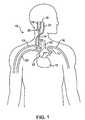
- FIG. 1is a schematic illustration of the upper torso of a human body showing the major arteries and veins and associated anatomy.
- FIG. 2Ais a cross-sectional schematic illustration of the carotid sinus and baroreceptors within the vascular wall.
- FIG. 2Bis a schematic illustration of baroreceptors within the vascular wall and the baroreflex system.
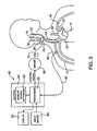
- FIG. 3is a schematic illustration of a baroreceptor activation system in accordance with the present invention.
- FIGS. 4A and 4Bare schematic illustrations of a baroreceptor activation device which electro-mechanically induces a baroreceptor signal in accordance with an embodiment of the present invention.
- FIGS. 5A-5Care schematic illustrations of baroreceptor activation devices in the form of an internal conductive structure, activated by an adjacent inductor, which electrically or thermally induces a baroreceptor signal in accordance with embodiments of the present invention.
- a transmitting coilis located remotely from an implanted control system, while in FIG. 5C , the transmitting coil or other antenna is located in the implanted control system itself.
- FIGS. 6A and 6Bare schematic illustrations of a baroreceptor activation device in the form of an internal conductive structure, activated by an internal inductor located in an adjacent vessel, which electrically or thermally induces a baroreceptor signal in accordance with an embodiment of the present invention.
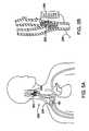
- FIGS. 7A and 7Bare schematic illustrations of a baroreceptor activation device in the form of an internal conductive structure, activated by an external (skin mounted) inductor, which electrically or thermally induces a baroreceptor signal in accordance with an embodiment of the present invention.
- FIGS. 8A and 8Bare schematic illustrations of an electromagnetic baroreceptor activation device which directly induces a baroreceptor signal via a thermal or electrical mechanism in accordance with an embodiment of the present invention.
- FIGS. 9A-9Care schematic illustrations of a preferred embodiment of an inductively activated electrically conductive structure.
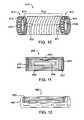
- FIG. 10illustrates an electrical intravascular baroreceptor activation device comprising a stent-like structure.
- FIGS. 11 and 12illustrate an electrical intravascular baroreceptor activation device including an electrode and receiving assembly wrapped or upon the outside surface of an intravascular stent
- FIGS. 13A-13Dillustrate alternative examples of electrode pad assemblies useful in the activation devices of the present invention.
- FIG. 14illustrates an electrical intravascular baroreceptor activation device comprising a tubular braided stent-like structure.
- FIG. 15is a detailed view of a portion of the stent structure of FIG. 14 , showing a bipolar design.
- FIGS. 16A and 16Bshow electrical activation circuits useful in the apparatus of the present invention.
- FIG. 17shows an electrical baroreceptor activation device according to the present invention which incorporates an electronics module.
- FIG. 18shows the embodiment of FIG. 17 with the electronic module disposed on an electrode/receiver coil assembly.
- FIG. 19is a schematic illustration of a wireless transmission arrangement where a coil activation device is implanted in an artery and a transmitting coil is implanted in an adjacent vein. The coils are aligned along a common axle.
- FIGS. 19A and 19Cillustrate alternative wireless transmission arrangements.
- FIG. 20shows an implanted baroreceptor activation device which hard wired to a control system in the lumen of an adjacent vein.
- FIGS. 21-24illustrate a catheter system including a stylet which may be used to implant and electrically connect a baroreceptor activation device in accordance with the principles of the present invention.
- FIGS. 25A-25Cillustrate a method of using the delivery catheter of FIGS. 21-24 for electrically connecting a braided stent-like activation structure in. accordance with the principles of the present invention.
- FIG. 1is a schematic illustration of the upper torso of a human body 10 showing some of the major arteries and veins of the cardiovascular system.
- the left ventricle of the heart 11pumps oxygenated blood up into the aortic arch 12 .
- the right subclavian artery 13 , the right common carotid artery 14 , the left common carotid artery 15 and the left subclavian artery 16branch off the aortic arch 12 proximal of the descending thoracic aorta 17 .
- brachiocephalic artery 22connects the right subclavian artery 13 and the right common carotid artery 14 to the aortic arch 12 .
- the right carotid artery 14bifurcates into the right external carotid artery 18 and the right internal carotid artery 19 at the right carotid sinus 20 .
- the left carotid artery 15similarly bifurcates into the left external carotid artery and the left internal carotid artery at the left carotid sinus.
- oxygenated bloodflows into the carotid arteries 18 / 19 and the subclavian arteries 13 / 16 .
- oxygenated bloodcirculates through the head and cerebral vasculature and oxygen depleted blood returns to the heart 11 by way of the jugular veins, of which only the right internal jugular vein 21 is shown for sake of clarity.
- oxygenated bloodcirculates through the upper peripheral vasculature and oxygen depleted blood returns to the heart by way of the subclavian veins, of which only the right subclavian vein 23 is shown, also for sake of clarity.
- the heart 11pumps the oxygen depleted blood through the pulmonary system where it is re-oxygenated.
- the re-oxygenated bloodreturns to the heart 11 which pumps the re-oxygenated blood into the aortic arch as described above, and the cycle repeats.
- baroreceptors 30Within the arterial walls of the aortic arch 12 , common carotid arteries 14 / 15 (near the right carotid sinus 20 and left carotid sinus), subclavian arteries 13 / 16 and brachiocephalic artery 22 there are baroreceptors 30 .
- baroreceptors 30reside within the vascular walls of the carotid sinus 20 .
- Baroreceptors 30are a type of stretch receptor used by the body to sense blood pressure. An increase in blood pressure causes the arterial wall to stretch, and a decrease in blood pressure causes the arterial wall to return to its original size. Such a cycle is repeated with each beat of the heart.
- baroreceptors 30are located within the arterial wall, they are able to sense deformation of the adjacent tissue, which is indicative of a change in blood pressure.
- the baroreceptors 30 located in the right carotid sinus 20 , the left carotid sinus and the aortic arch 12play the most significant role in sensing blood pressure that affects the baroreflex system 50 , which is described in more detail with reference to FIG. 2B .
- FIG. 2Bshows a schematic illustration of baroreceptors 30 disposed in a generic vascular wall 40 and a schematic flow chart of the baroreflex system 50 .
- Baroreceptors 30are profusely distributed within the arterial walls 40 of the major arteries discussed previously, and generally form an arbor 32 .
- the baroreceptor arbor 32comprises a plurality of baroreceptors 30 , each of which transmits baroreceptor signals to the brain 52 via nerve 38 .
- the baroreceptors 30are so profusely distributed and arborized within the vascular wall 40 that discrete baroreceptor arbors 32 are not readily discernable.
- FIG. 2Bare primarily schematic for purposes of illustration and discussion.
- Baroreceptor signalsare used to activate a number of body systems which collectively may be referred to as the baroreflex system 50 .
- Baroreceptors 30are connected to the brain 52 via the nervous system 51 .
- the brain 52is able to detect changes in blood pressure, which is indicative of cardiac output. If cardiac output is insufficient to meet demand (i.e., the heart 11 is unable to pump sufficient blood), the baroreflex system 50 activates a number of body systems, including the heart 11 , kidneys 53 , vessels 54 , and other organs/tissues. Such activation of the baroreflex system 50 generally corresponds to an increase in neurohormonal activity.
- the baroreflex system 50initiates a neurohormonal sequence that signals the heart 11 to increase heart rate and increase contraction force in order to increase cardiac output, signals the kidneys 53 to increase blood volume by retaining sodium and water, and signals the vessels 54 to constrict to elevate blood pressure.
- the cardiac, renal and vascular responsesincrease blood pressure and cardiac output 55 , and thus increase the workload of the heart 11 . In a patient with heart failure, this further accelerates myocardial damage and exacerbates the heart failure state.
- the present inventionbasically provides a number of devices, systems and methods by which the baroreflex system 50 is activated to reduce excessive blood pressure, autonomic nervous system activity and neurohormonal activation.
- the present inventionprovides a number of devices, systems and methods by which baroreceptors 30 may be activated, thereby indicating an increase in blood pressure and signaling the brain 52 to reduce the body's blood pressure and level of sympathetic nervous system and neurohormonal activation, and increase parasypathetic nervous system activation, thus having a beneficial effect on the cardiovascular system and other body systems.
- the present inventiongenerally provides a system including a control system 60 , a baroreceptor activation device 70 , and a sensor 80 (optional), which generally operate in the following manner.
- the sensor 80optionally senses and/or monitors a parameter (e.g., cardiovascular function) indicative of the need to modify the baroreflex system and generates a signal indicative of the parameter.
- the sensor 80may be incorporated into the structure of the activation device 70 .
- the control system 60generates a control signal as a function of the received sensor signal.
- the control signalactivates, deactivates or otherwise modulates the baroreceptor activation device 70 .
- activation of the device 70results in activation of the baroreceptors 30 .
- deactivation or modulation of the baroreceptor activation device 70may cause or modify activation of the baroreceptors 30 .
- the baroreceptor activation device 70may comprise a wide variety of devices which utilize mechanical, electrical, thermal, chemical, biological, or other means to activate baroreceptors 30 .
- the control system 60when the sensor 80 detects a parameter indicative of the need to modify the baroreflex system activity (e.g., excessive blood pressure), the control system 60 generates a control signal to modulate (e.g.
- the control system 60When the sensor 80 detects a parameter indicative of normal body function (e.g., normal blood pressure), the control system 60 generates a control signal to modulate (e.g., deactivate) the baroreceptor activation device 70 .
- a parameter indicative of normal body functione.g., normal blood pressure
- the baroreceptor activation device 70may directly activate one or more baroreceptors 30 by changing the electrical potential across the baroreceptors 30 . It is also possible that changing the electrical potential might indirectly change the thermal or chemical potential across the tissue surrounding the baroreceptors 30 and/or otherwise may cause the surrounding tissue to stretch or otherwise deform, thus mechanically activating the baroreceptors 30 .
- the baroreceptor activation device 70are suitable for implantation, and are preferably implanted using a minimally invasive percutaneous transluminal approach and/or a minimally invasive surgical approach.
- the baroreceptor activation device 70may be positioned anywhere baroreceptors 30 effecting the baroreflex system 50 are numerous, such as in the heart 11 , in the aortic arch 12 , in the common carotid arteries 18 / 19 near the carotid sinus 20 , in the subclavian arteries 13 / 16 , or in the brachiocephalic artery 22 .
- the baroreceptor activation device 70may be implanted such that the device 70 is positioned immediately adjacent the baroreceptors 30 .
- the baroreceptor activation device 70may be outside the body such that the device 70 is positioned a short distance from but proximate to the baroreceptors 30 .
- the baroreceptor activation device 70is implanted near the right carotid sinus 20 and/or the left carotid sinus (near the bifurcation of the common carotid artery) and/or the aortic arch 12 , where baroreceptors 30 have a significant impact on the baroreflex system 50 .
- the present inventionis described with reference to baroreceptor activation device 70 positioned near the carotid sinus 20 .
- the optional sensor 80is operably coupled to the control system 60 by electric sensor cable or lead 82 .
- the sensorcould be coupled “wirelessly” and/or could be located on the activation device 70 .
- the sensor 80may comprise any suitable device that measures or monitors a parameter indicative of the need to modify the activity of the baroreflex system.
- the sensor 80may comprise a physiologic transducer or gauge that measures ECG, blood pressure (systolic, diastolic, average or pulse pressure), blood volumetric flow rate, blood flow velocity, blood pH, O2 or CO2 content, mixed venous oxygen saturation (SVO2), vasoactivity, nerve activity, tissue activity or composition.
- suitable transducers or gauges for the sensor 80include ECG electrodes, a piezoelectric pressure transducer, an ultrasonic flow velocity transducer, an ultrasonic volumetric flow rate transducer, a thermodilution flow velocity transducer, a capacitive pressure transducer, a membrane pH electrode, an optical detector (SVO2) or a strain gage. Although only one sensor 80 is shown, multiple sensors 80 of the same or different type at the same or different locations may be utilized.
- An example of an implantable blood pressure measurement device that may be disposed about a blood vesselis disclosed in U.S. Pat. No. 6,106,477 to Miesel et al., the entire disclosure of which is incorporated herein by reference.
- An example of a subcutaneous ECG monitoris available from Medtronic under the trade name REVEAL ILR and is disclosed in PCT Publication No. WO 98/02209, the entire disclosure of which is incorporated herein by reference.
- Other examplesare disclosed in U.S. Pat. Nos. 5,987,352 and 5,331,966, the entire disclosures of which are incorporated herein by reference. Examples of devices and methods for measuring absolute blood pressure utilizing an ambient pressure reference are disclosed in U.S. Pat. No.
- the sensor 80is preferably positioned in a chamber of the heart 11 , or in/on a major artery such as the aortic arch 12 , a common carotid artery 14 / 15 , a subclavian artery 13 / 16 or the brachiocephalic artery 22 , such that the parameter of interest may be readily ascertained.
- the sensor 80may be disposed inside the body such as in or on an artery, a vein or a nerve (e.g. vagus nerve), or disposed outside the body, depending on the type of transducer or gauge utilized.
- the sensor 80may be separate from the baroreceptor activation device 70 or combined therewith. For purposes of illustration only, the sensor 80 is shown positioned on the right subclavian artery 13 .
- control system 60includes a control block 61 comprising a processor 63 and a memory 62 .
- Control system 60is connected to the sensor 80 by way of sensor cable 82 .
- Control system 60is also connected to the baroreceptor activation device 70 by way of electric control cable 72 .
- the control system 60receives a sensor signal from the sensor 80 by way of sensor cable 82 , and transmits a control signal to the baroreceptor activation device 70 by way of control cable 72 .
- the system components 60 / 70 / 80may be directly linked via cables 72 / 82 or by indirect means such as RF signal transceivers, ultrasonic transceivers or galvanic couplings. Examples of such indirect interconnection devices are disclosed in U.S. Pat. No. 4,987,897 to Funke and U.S. Pat. No. 5,113,859 to Funke, the entire disclosures of which are incorporated herein by reference.
- the memory 62may contain data related to the sensor signal, the control signal, and/or values and commands provided by the input device 64 .
- the memory 62may also include software containing one or more algorithms defining one or more functions or relationships between the control signal and the sensor signal.
- the algorithmmay dictate activation or deactivation control signals depending on the sensor signal or a mathematical derivative thereof.
- the algorithmmay dictate an activation or deactivation control signal when the sensor signal falls below a lower predetermined threshold value, rises above an upper predetermined threshold value or when the sensor signal indicates a specific physiologic event.
- the algorithmmay dynamically alter the threshold value as determined by the sensor input values.
- the baroreceptor activation device 70activates baroreceptors 30 electrically, optionally in combination with mechanical, thermal, chemical, biological or other co-activation.
- the control system 60includes a driver 66 to provide the desired power mode for the baroreceptor activation device 70 .
- the driver 66may comprise a power amplifier or the like and the cable 72 may comprise electrical lead(s).
- the driver 66may not be necessary, particularly if the processor 63 generates a sufficiently strong electrical signal for low level electrical actuation of the baroreceptor activation device 70 .
- the control system 60may operate as a closed loop utilizing feedback from the sensor 80 , or other sensors, such as heart rate sensors which may be incorporated on the electrode assembly, or as an open loop utilizing reprogramming commands received by input device 64 .
- the closed loop operation of the control system 60preferably utilizes some feedback from the transducer 80 , but may also operate in an open loop mode without feedback.
- Programming commands received by the input device 64may directly influence the control signal, the output activation parameters, or may alter the software and related algorithms contained in memory 62 .
- the treating physician and/or patientmay provide commands to input device 64 .
- Display 65may be used to view the sensor signal, control signal and/or the software/data contained in memory 62 .
- the control signal generated by the control system 60may be continuous, periodic, alternating, episodic or a combination thereof, as dictated by an algorithm contained in memory 62 .
- Continuous control signalsinclude a constant pulse, a constant train of pulses, a triggered pulse and a triggered train of pulses.
- periodic control signalsinclude each of the continuous control signals described above which have a designated start time (e.g., beginning of each period as designated by minutes, hours, or days in combinations of) and a designated duration (e.g., seconds, minutes, hours, or days in combinations of).
- Examples of alternating control signalsinclude each of the continuous control signals as described above which alternate between the right and left output channels.
- Examples of episodic control signalsinclude each of the continuous control signals described above which are triggered by an episode (e.g., activation by the physician/patient, an increase/decrease in blood pressure above a certain threshold, heart rate above/below certain levels, etc.).
- the stimulus regimen governed by the control system 60may be selected to promote long term efficacy. It is theorized that uninterrupted or otherwise unchanging activation of the baroreceptors 30 may result in the baroreceptors and/or the baroreflex system becoming less responsive over time, thereby diminishing the long term effectiveness of the therapy. Therefore, the stimulus regimen maybe selected to activate, deactivate or otherwise modulate the baroreceptor activation device 70 in such a way that therapeutic efficacy is maintained for months, preferably for years.
- the stimulus regimens of the present inventionmay be selected reduce power requirement/consumption of the system 60 .
- the stimulus regimenmay dictate that the baroreceptor activation device 70 be initially activated at a relatively higher energy and/or power level, and subsequently activated at a relatively lower energy and/or power level.
- the first levelattains the desired initial therapeutic affect
- the second (lower) levelsustains the desired therapeutic affect long term.
- the energy required or consumed by the activation device 70is also reduced long term. This may correlate into systems having greater longevity and/or reduced size (due to reductions in the size of the power supply and associated components).
- a first general approach for a stimulus regimen which promotes long term efficacy and reduces power requirements/consumptioninvolves generating a control signal to cause the baroreceptor activation device 70 to have a first output level of relatively higher energy and/or power, and subsequently changing the control signal to cause the baroreceptor activation device 70 to have a second output level of relatively lower energy and/or power.
- the first output levelmay be selected and maintained for sufficient time to attain the desired initial affect (e.g., reduced heart rate and/or blood pressure), after which the output level may be reduced to the second level for sufficient time to sustain the desired affect for the desired period of time.
- the second output levelmay have a power and/or energy value of X 2 , wherein X 2 is less than X 1 .
- X 2may be equal to zero, such that the first level is “on” and the second level is “off”.
- power and energyrefer to two different parameters, and in some cases, a change in one of the parameters (power or energy) may not correlate to the same or similar change in the other parameter. In the present invention, it is contemplated that a change in one or both of the parameters may be suitable to obtain the desired result of promoting long term efficacy.
- each further levelmay increase the output energy or power to attain the desired affect, or decrease the output energy or power to retain the desired affect. For example, in some instances, it may be desirable to have further reductions in the output level if the desired affect may be sustained at lower power or energy levels. In other instances, particularly when the desired affect is diminishing or is otherwise not sustained, it may be desirable to increase the output level until the desired affect is reestablished, and subsequently decrease the output level to sustain the affect.
- the transition from each levelmay be a step function (e.g., a single step or a series of steps), a gradual transition over a period of time, or a combination thereof.
- the signal levelsmay be continuous, periodic, alternating, or episodic as discussed previously.
- the output (power or energy) level of the baroreceptor activation device 70may be changed by adjusting the output signal voltage level, current level and/or signal duration.
- the output signal of the baroreceptor activation device 70may be, for example, constant current or constant voltage.
- several pulse characteristicsmay be changed individually or in combination to change the power or energy level of the output signal.
- Such pulse characteristicsinclude, but are not limited to: pulse amplitude (PA), pulse frequency (PF), pulse width or duration (PW), pulse waveform (square, triangular, sinusoidal, etc.), pulse polarity and pulse phase (monophasic, biphasic), and sequential.
- the control system 60may be implanted in whole or in part.
- the entire control system 60may be carried externally by the patient utilizing transdermal connections to the sensor lead 82 and the control lead 72 .
- the control block 61 and driver 66may be implanted with the input device 64 and display 65 carried externally by the patient utilizing transdermal connections therebetween.
- the transdermal connectionsmay be replaced by cooperating transmitters/receivers to remotely communicate between components of the control system 60 and/or the sensor 80 and baroreceptor activation device 70 .
- FIGS. 4-9schematic illustrations of specific embodiments of the baroreceptor activation device 70 are shown.
- the design, function and use of these specific embodiments, in addition to the control system 60 and sensor 80 (not shown),are the same as described with reference to FIG. 3 , unless otherwise noted or apparent from the description.
- the anatomical features illustrated in FIGS. 4-8are the same as discussed with reference to FIGS. 1 , 2 A and 2 B, unless otherwise noted.
- the connections between the components 60 / 70 / 80may be physical (e.g., wires, tubes, cables, etc.) or remote (e.g., transmitter/receiver, inductive, magnetic, etc.).
- the connectionmay travel intra-arterially, intravenously, subcutaneously, or through other natural tissue paths.
- FIGS. 4A and 4Bshow schematic illustrations of a 30 baroreceptor activation device 220 in the form of magnetic particles 222 disposed in the vascular wall 40 .
- the magnetic particles 222may comprise magnetically responsive materials (i.e., ferrous based materials) and may be magnetically neutral or magnetically active.
- the magnetic particles 222comprise permanent magnets having an elongate cylinder shape with north and south poles to strongly respond to magnetic fields.
- the magnetic particles 222are actuated by an electromagnetic coil 224 which is operably coupled to the driver 66 of the control system 60 by way of an electrical cable 226 .
- the electromagnetic coil 224may be implanted as shown, or located outside the body, in which case the driver 66 and the remainder of the control system 60 would also be located outside the body.
- the electromagnetic coil 224By selectively activating the electromagnetic coil 224 to create a magnetic field, the magnetic particles 222 may be repelled, attracted or rotated.
- the magnetic field created by the electromagnetic coil 224may be alternated such that the magnetic particles 222 vibrate within the vascular wall 40 .
- the baroreceptors 30are mechanically activated.
- the electromagnetic coil 224is preferably placed as close as possible to the magnetic particles 222 in the vascular wall 40 , and may be placed intravascularly, extravascularly, or in any of the alternative locations discussed with reference to inductor shown in FIGS. 5-7 .
- the magnetic particles 222may be implanted in the vascular wall 40 by injecting a ferro-fluid or a ferro-particle suspension into the vascular wall adjacent to the baroreceptors 30 .
- the particles 222may be coated with a ceramic, polymeric or other inert material. Injection of the fluid carrying the magnetic particles 222 is preferably performed percutaneously.
- Electrical activation signalsmay be indirectly delivered utilizing an inductor as illustrated in FIGS. 5-9 .
- the embodiments of FIGS. 5-7utilize an inductor 286 which is operably connected to the driver 66 of the control system 60 by way of electrical lead 284 .
- the inductor 286comprises an electrical winding which creates a magnetic field 287 (as seen in FIG. 9 ) around the electrode structure 282 .
- the magnetic field 287may be alternated by alternating the direction of current flow through the inductor 286 .
- the inductor 286may be utilized to create current flow in the electrode structure 282 to thereby deliver electrical signals to the vascular wall 40 to directly or indirectly activate the baroreceptors 30 .
- the inductor 286may be covered with an electrically insulating material to eliminate direct electrical stimulation of tissues surrounding the inductor 286 .
- an inductively activated electrode structure 282is described in more detail with reference to FIGS. 9A-9C .
- FIGS. 5-7may be modified to form a cathode/anode arrangement.
- the electrical inductor 286would be connected to the driver 66 as shown in FIGS. 5-7 and the electrode structure 282 would be connected to the driver 66 .
- the electrode structure 282 and the inductor 286may be any suitable geometry and need not be coiled for purposes of induction.
- the electrode structure 282 and the inductor 286would comprise a cathode/anode or anode/cathode pair.
- the cathode 282when activated, may generate a primary stream of electrons which travel through the inter-electrode space (i.e., vascular tissue and baroreceptors 30 ) to the anode 286 .
- the cathodeis preferably cold, as opposed to thermionic, during electron emission.
- the electronsmay be used to electrically or thermally activate the baroreceptors 30 as discussed previously.
- the electrical inductor 286is preferably disposed as close as possible to the electrode structure 282 .
- the electrical inductor 286may be disposed adjacent the vascular wall as illustrated in FIGS. 5A and 5B .
- the inductor 286may be disposed in an adjacent vessel as illustrated in FIGS. 6A and 6B .
- the electrode structure 282is disposed in the carotid sinus 20
- the inductor 286may be disposed in the internal jugular vein 21 as illustrated in FIGS. 6A and 6B .
- the electrical inductor 286may comprise a similar structure as the electrode structure 282 .
- the electrical inductor 286may be disposed outside the patient's body, but as close as possible to the electrode structure 282 . If the electrode structure 282 is disposed in the carotid sinus 20 , for example, the electrical inductor 286 may be disposed on the right or left side of the neck of the patient as illustrated in FIGS. 7A and 7B . In the embodiment of FIGS. 7A and 7B , wherein the electrical inductor 286 is disposed outside the patient's body, the control system 60 may also be disposed outside the patient's body.
- the electrode structure 282may be intravascularly disposed as described with reference to FIGS. 6A and 6B , or extravascularly disposed. Except as described herein, the extravascular electrode structure is the same in design, function, and use as the intravascular electrode structure 282 .
- the electrode structuremay comprise a coil, braid or other structure capable of surrounding the vascular wall.
- the electrode structuremay comprise one or more electrode patches distributed around the outside surface of the vascular wall. Because the electrode structure is disposed on the outside surface of the vascular wall, intravascular delivery techniques may not be practical, but minimally invasive surgical techniques will suffice.
- FIGS. 8A and 8Bshow schematic illustrations of a baroreceptor activation device 320 in the form of electrically conductive particles 322 disposed in the vascular wall.
- This embodimentis substantially the same as the embodiments described with reference to FIGS. 5-7 , except that the electrically conductive particles 322 are disposed within the vascular wall, as opposed to the electrically conductive structures 288 which are disposed on either side of the vascular wall.
- the driver 66 of the control system 60comprises an electromagnetic transmitter such as a radiofrequency or microwave transmitter. Electromagnetic radiation is created by the transmitter 66 which is operably coupled to an antenna 324 by way of electrical lead 326 . Electromagnetic waves are emitted by the antenna 324 and received by the electrically conductive particles 322 disposed in the vascular wall 40 . Electromagnetic energy creates oscillating current flow within the electrically conductive particles 322 , and depending on the intensity of the electromagnetic radiation and the resistivity of the conductive particles 322 , may cause the electrical particles 322 to generate heat. The electrical or thermal energy generated by the electrically conductive particles 322 may directly activate the baroreceptors 30 , or indirectly activate the baroreceptors 30 by way of the surrounding vascular wall tissue.
- an electromagnetic transmittersuch as a radiofrequency or microwave transmitter.
- Electromagnetic radiationis created by the transmitter 66 which is operably coupled to an antenna 324 by way of electrical lead 326 . Electromagnetic waves are emitted by the antenna
- the electromagnetic radiation transmitter 66 and antenna 324may be disposed in the patient's body, with the antenna 324 disposed adjacent to the conductive particles in the vascular wall 40 as illustrated in FIGS. 8A and 8B .
- the antenna 324may be disposed in any of the positions described with reference to the electrical inductor shown in FIGS. 5-7 .
- the electromagnetic radiation transmitter 66 and antenna 324may be utilized in combination with the intravascular and extravascular electrically conductive structures 282 (acting like heater coils) described with reference to FIGS. 5-7 to generate thermal energy on either side of the vascular wall.
- the electromagnetic radiation transmitter 66 and antenna 324may be used without the electrically conductive particles 322 .
- the electromagnetic radiation transmitter 66 and antenna 324may be used to deliver electromagnetic radiation (e.g., RF, microwave) directly to the baroreceptors 30 or the tissue adjacent thereto to cause localized heating, thereby thermally inducing a baroreceptor 30 signal.
- electromagnetic radiatione.g., RF, microwave
- FIGS. 9A-9Cshow schematic illustrations of a specific embodiment of an inductively activated electrode structure 282 for use with the embodiments described with reference to FIGS. 5-7 .
- current flow in the electrode structure 282is induced by a magnetic field 287 created by an inductor 286 which is operably coupled to the driver 66 of the control system 60 by way of electrical cable 284 .
- the electrode structure 282preferably comprises a multi-filar self-expanding braid structure including a plurality of individual members 282 a , 282 b , 282 c and 282 d .
- the electrode structure 282may simply comprise a single coil for purposes of this embodiment.
- Each of the individual coil members 282 a - 282 d comprising the electrode structure 282consists of a plurality of individual coil turns 281 connected end to end as illustrated in FIGS. 9B and 9C .
- FIG. 9Cis a detailed view of the connection between adjacent coil turns 281 as shown in FIG. 9B .
- Each coil turn 281comprises electrically isolated wires or receivers in which a current flow is established when a changing magnetic field 287 is created by the inductor 286 .
- the inductor 286is preferably covered with an electrically insulating material to eliminate direct electrical stimulation of tissues surrounding the inductor 286 .
- Current flow through each coil turn 281results in a potential drop 288 between each end of the coil turn 281 .
- each coil turn 281comprises an electrically conductive wire material 290 surrounded by an electrically insulating material 292 .
- the ends of each coil turn 281are connected by an electrically insulated material 294 such that each coil turn 281 remains electrically isolated.
- the insulating material 294mechanically joins but electrically isolates adjacent coil turns 281 such that each turn 281 responds with a similar potential drop 288 when current flow is induced by the changing magnetic field 287 of the inductor 286 .
- An exposed portion 296is provided at each end of each coil turn 281 to facilitate contact with the vascular wall tissue.
- Each exposed portion 296comprises an isolated electrode in contact with the vessel wall.
- the changing magnetic field 287 of the inductor 286causes a potential drop in each coil turn 281 thereby creating small current flow cells in the vessel wall corresponding to adjacent exposed regions 296 .
- the creation of multiple small current cells along the inner wall of the blood vesselserves to create a cylindrical zone of relatively high current density such that the baroreceptors 30 are activated.
- the cylindrical current density fieldquickly reduces to a negligible current density near the outer wall of the vascular wall, which serves to limit extraneous current leakage to minimize or eliminate unwanted activation of extravascular tissues and structures such as nerves or muscles.
- the electrical baroreceptor activation devicescomprise stent like structures that may be directly or wirelessly coupled to the control system 60 as described previously.
- wireless transmission of electrical energymay be employed as described in U.S. Pat. No. 6,231,516 to Keilman et al., the entire disclosure of which is hereby incorporated by reference.
- the stent like structuresmay comprise conventional intravascular stents that carry one or more electrodes and/or receiving coils, or a portion of the stent like structure may serve as one or more electrodes and/or receiving coils.
- the stent like structuresmay be intravascularly delivered in a collapsed state, and deployed to an expanded state in much the same way that intravascular stents are implanted in coronary and peripheral applications.
- the electrical intravascular baroreceptor activation device 610comprises a stent like structure having a coil mid portion 612 and two ratcheting end portions 614 .
- the coil mid portion 612unwinds as the device 610 is deployed in the vessel lumen, and the ratcheting ends portions 614 selectively expand (self expanded or balloon expanded) to the desired diameter, with tabs 615 engaging openings 616 to lock the device 610 in the expanded state.
- stent like structuresmay be employed as well, such as self expanding stent structures.
- the coil mid portion 612may comprise an insulated conductive metal such as MP 35, SST, or a NiTi alloy, and may serve as an RF receiving coil which receives RF transmissions from an antenna or coupling coil (not shown) connected to the control system 60 .
- the winding axis of the coil 612is common with the longitudinal center axis of the tubular device 610 .
- the ratcheting end portions 614may comprise a conductive material such as MP 35, SST, or a NiTi alloy, with the inside surface of the end portions 614 insulated and the outside surface of the end portions 614 at least partially uninsulated to serve as electrodes which contact the inside surface of the vessel wall.
- the end portions 614may incorporate conductive barbs to serve as electrodes which extend into the vascular wall upon expansion of the device 610 .
- One end 611 of the coil 612is connected to one end portion 614
- the other end 613 of the coil 612is connected to the other end portion 614 .
- a signal transmitted by control system 60is received by the coil 612 and travels to inside surface of the vascular wall adjacent baroreceptors via the outside surface of the end portions 614 .
- an electronics module 670may be electrically connected between the end portions 614 and mounted to the mid portion 612 , for example.
- the electronics module 670may comprise a tuning capacitor, for example, as will be described in more detail hereinafter.
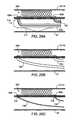
- FIGS. 11 and 12illustrate an electrical intravascular baroreceptor activation device 620 , including an electrode and receiving coil assembly 630 wrapped about the outside surface of an intravascular stent 640 .
- the electrode and receiving coil assembly 630may be movably attached to the intravascular stent 640 to permit free expansion of the stent 640 , and/or may be made expandable to permit expansion of the assembly 630 with expansion of the stent 640 .
- Stent 640may comprise a self expanding stent, a balloon expandable stent, or any of a wide variety of other types of intravascular stents known to those skilled in the art.
- the stent 640is shown in the form of a tubular metal stent having a plurality of slots.
- the assembly 630 shown in FIG. 11may be in the shape of a semi cylinder (shown) or tubular sleeve (not shown) and may include a receiving coil 632 and one or more electrode pads 634 .
- the coil 632 and the pads 634may comprise a conductive metal such as Pt or a Pt alloy disposed on a flex circuit substrate material 636 such as polyimide.
- the metalmay be laminated on the flex circuit substrate 636 and may be chemically etched to define the pattern of the coil 632 and pads 634 .
- One end 631 of the coil 632is connected to one of the electrode pads 634
- the other end 633 of the coil 632is connected via a backside tracer to the other electrode pad 634 .
- a signal transmitted by control system 60is received by the coil 632 and travels to inside surface of the vascular wall adjacent baroreceptors via the electrode pads 634 .
- An electronics module 670may be electrically connected via backside tracers between the pads 634 and mounted to the substrate 636 , for example.
- the electronics module 670may comprise a tuning capacitor, for example, as will be described in more detail hereinafter.
- the assembly 630may include both the receiving coil 632 and the electrode pads 634 , or simply the electrode pads 634 without the coil 632 as when the device 620 is hard wired to the control system 60 .
- the electrode pads 634may be shaped and arranged in a wide variety of manners, a few examples of which are shown in FIGS. 13A-13D .
- the pads 634are disposed about the ends of the substrate 636 substantially parallel to the circumference.
- the padsare disposed about the mid portion of the substrate 636 substantially parallel to the longitudinal axis.
- the electrode pads 634comprise circles or concentric rings distributed about the substrate 636 .
- the pads 634are disposed along the entire substrate 636 substantially parallel to the circumference.
- FIG. 14illustrates an electrical intravascular baroreceptor activation device 650 comprising a tubular braided stent like structure, for example.
- the intravascular electrical baroreceptor activation device 650may comprise a wide variety of stent like structures including, without limitation, self expanding multi-filar braid, self expanding interconnected zig-zag bands, self expanding coil bands, etc.
- elastic self expanding stent like structuresmay be preferred to avoid accidental collapse if the device is to be implanted in the carotid sinus which is relatively unprotected from external forces.
- Localized cellsmay be created, for example, by spacing the electrodes or poles very close together (e.g., ⁇ 1 mm), placing the anode in a carotid artery and placing the cathode in an adjacent jugular vein (or vice versa), biasing the electrical filed with conductors and/or magnetic fields (e.g., an electrical field generator in the jugular vein with a conductive device in the carotid sinus to attract the field), etc.
- the electrical fieldmay be directed from one or more intravascular and/or extravascular electrical activation devices disposed near the CSN.
- one electrodemay be placed in the external carotid artery and another electrode may be placed in the internal carotid artery, or one electrode may be placed in the external carotid artery and another electrode may be placed in the jugular vein, etc.
- the electrical field created between the electrodesmay be used to stimulate the CSN for baropacing applications.
- the braided tube structure 650includes a plurality of interwoven members 652 / 654 , one set 652 (e.g., half) of which are helically wound in one direction (e.g., CW) and another set 654 (e.g., the other half) of which are helically wound in the other direction (e.g., CCW).
- one set of membersis shown in black thick lines and the other set is shown in gray thick lines (the thin lines represent members running along the back side of the tubular device 650 ). For example, in a 16 wire braid, 8 members run CW, and 8 members run CCW.
- One set of members 652comprises electrically conductive wires, and the other set of members comprises electrically insulating members 654 .
- the electrically conductive wires 652may comprise a conductive metal such as MP 35N, SST, Elgiloy, or a NiTi alloy, and the electrically insulating members 654 may comprise a non-conductive material such as a polymer or a metal wire covered by a non-conductive insulating material, for example. Because the electrically conductive wires 652 run in the same helical direction, each wire remains electrically isolated from adjacent wires. In addition, the electrically insulating members 654 aid in maintaining the electrical isolation of each conductive wire 652 by maintaining the spacing between adjacent wires 652 . To this end, each conductive wire 652 acts like a helically extending electrode.
- adjacent membersmay have a dissimilar polarity so as to create current flow 658 between adjacent wires as shown in FIG. 15 .
- every other wire 652may have a positive polarity, with every other remaining wire having a negative polarity (bipolar or anode/cathode arrangement).
- the electrical fieldmay be in the form of a series of helices having a width substantially equal to the spacing between adjacent wires 652 .
- the wires 652may have a bipolar, tripolar, or any other multipolar arrangement, depending on how each wire 652 is connected to and activated by the control system 60 .
- the control system 60(not shown) may be coupled to the conductive wires 652 by cable 656 .
- Cable 656may be hardwired to the control system 60 or wirelessly coupled to the control system by incorporating a receiver coil in or near the device 650 .
- an electronics module 670(not shown) may be electrically connected to adjacent wires 652 .
- the electrical activation embodimentsmay create an L C circuit as shown in the schematic 660 shown in FIG. 16A .
- an L C circuitmay be created between electrode contacts when using a receiving coil (L) due to the parasitic capacitance (CP) of tissue (e.g., vascular wall tissue), and thus the device would potentially have a resonating frequency.
- an electronics module 670such as a tuning circuit or a simple capacitor (C) may be employed to create an L C tuned circuit as shown in FIG. 16B .
- the EM or RF signal generated by the control systemmay be located within the body (e.g., neck) or outside the body.
- the activation devices described hereinmay be passive with the intelligence carried by the control system 60 .
- the activation devicesmay incorporate intelligence in the form of an electronics module 670 which cooperates with the control system 60 to actively control power transmission, activation energy, activation regimen, electrode activation sequencing, etc.
- the activation devicemay incorporate an electronics module 670 .
- the electronics module 670may be disposed on the electrode/receiver coil assembly 630 (to be deployed for example on a stent-like electrode assembly) as shown in FIG. 18 .
- the electronics module 670may include a power supply circuit 672 which receives power from the EM energy transmitted by the control system 60 to a receiver coil 671 of the activation device.
- the electronics module 670may include a signal decoding circuit 674 to decode an encoded signal transmitted by the control system 60 .
- the electronics modulemay also include an activation control circuit 676 that delivers the desired electrical signals to specific electrodes as a function of an internal algorithm and the decoded information received from circuit 674 .
- the module 670may be configured to both receive and transmit back encoded information. Data to be sent backing include pressure, pulse, or other information obtained from sensors on the activation device or elsewhere.
- intravascular electrical baroreceptor activation device 620is shown in FIG. 19 , including the flexible receiver coil and electrode circuit assembly 630 deployed on the outer surface of a stent-like or other electrode structure 640 .
- the activation device 620may be disposed in the artery containing the baroreceptors, such as internal carotid artery 19 or common carotid artery 14 .
- a transmitting device 680may be disposed in an adjacent vein such as jugular vein 21 which lies in close proximity to the internal carotid artery 19 and the common carotid artery 14 .
- the transmitting deviceincludes a coil assembly 682 disposed on a stent like tubular structure 684 , similar to the construction and arrangement of assembly 630 disposed on stent like structure 640 as described previously.
- the coil assembly 682emits an RF or other EM signal picked up by coil assembly 630 on the activation device 620 .
- the coil assembly 682 on the transmitting device 680acts as an antenna and is operably coupled to the control system 60 (not shown) via leads 686 which travel down the vein 21 to a remote entry site.
- leads 686 in the venous side of the vascular systemis less concerning due to the reduced risk of thromboembolism and stroke.
- FIG. 19illustrates coupling between two generally “planar” coils which are arranged face-to-face in adjacent blood vessels.
- FIGS. 19A-19Cillustrate alternative embodiments.
- a helical transmitting coil 691is positioned in a first blood vessel and a helical receiving coil 693 is positioned in a second blood vessel immediately adjacent the transmitting coil.
- the coil axesare aligned, and transmissions may be made as described previously.
- the coils 691 and 693may also be arranged with parallel axes, but longitudinally separated, as shown in FIG. 19B , and a specific implantation in the common carotid artery CC is shown if FIG. 19C .
- the activation device 620may be hard wired to the control system 60 as shown in FIG. 20 .
- the activation device 620may be disposed in the artery containing the baroreceptors, such as internal carotid artery 19 or common carotid artery 14 .
- the activation deviceincludes two or more laterally facing extensions or barbs 638 which extend through the arterial wall and into an adjacent vein such as jugular vein 21 , which lies in close proximity to the internal carotid artery 19 and the common carotid artery 14 .
- the electrode pads 634are electrically connected to the extensions 638 which are coupled to the control system 60 (not shown) via leads 639 which travel down the vein 21 to a remote entry site.
- leads 639 in the venous side of the vascular systemis less concerning due to the reduced risk of thromboembolism and stroke.
- FIGS. 21-25schematically illustrate tools and methods for making a connection between an electrical activation device disposed in or on a vessel containing baroreceptors (e.g., carotid artery 14 / 19 ) and leads disposed in an adjacent vessel (e.g., jugular vein 21 ).
- the tools and methods described with reference to FIGS. 21-25facilitate minimally invasive transluminal techniques, and presume the activation device 650 has been previously implanted by minimally invasive transluminal techniques, for example.
- These tools and methodsmay be applied to many of the intravascular electrical activation devices described herein, and are described with reference to braided stent like structure 650 for sake of illustration, not limitation.
- FIG. 24illustrates a top view of a distal portion of a delivery catheter 710 .
- Catheter 710is sized and adapted for intravascular insertion and navigation from a remove vascular access point leading to the jugular vein 21 adjacent the carotid sinus 20 .
- FIG. 22is a longitudinal sectional view taken along line 22 - 22 in FIG. 21
- FIG. 23is a cross sectional view taken along line 23 - 23 in FIG. 21 .
- catheter 710includes an elongate shaft 712 with a first pair of lumens 714 leading to proximal ports 715 , and a second pair of lumens 716 leading to distal ports 717 .
- a plane of separability 718such as a peelable scam may be provided along the centerline of the shaft 712 to permit subsequent removal over the leads as will be described in more detail hereinafter.
- FIG. 25illustrates a distal portion of a curved stylet 720 formed of a flexible metal such as NiTi, for example.
- the stylet 720includes an elongate shaft 722 that is sized and adapted to be inserted and advanced through the lumens 714 / 716 of the delivery catheter 710 .
- the distal end of the stylet 720includes a sharpened tip 724 to facilitate tissue penetration.
- a distal portion of the stylet 720includes a primary curve 726 having a resting nominal diameter roughly equal to the distance between the center points of the ports 715 / 717 of the delivery catheter 710 .
- the distal portion of the stylet 720may also include a secondary curve 728 to facilitate orientation of the primary curve 726 relative to the catheter 710 as the stylet is advanced out of the ports 715 / 717 .
- FIGS. 25A-25Cillustrate a method of using the delivery catheter 710 and two stylets 720 to make an electrical connection to the braided stent like structure 650 .
- two separate and relatively short tail leads 656are provided corresponding to each set of conductive members 652 .
- the short tail leads 656may be uninsulated to ensure good electrical connection.
- a biasing member 711such as a deflection wire or eccentric balloon may be incorporated into the delivery catheter 710 to urge the ports 715 / 717 into contact with the inside surface of the vein 19 .
- the delivery catheter 710is navigated to the jugular vein 21 until the distal portion thereof is adjacent the activation device 650 previously deployed in the artery 14 / 19 as seen in FIG. 25A .
- Stylets 720are then advanced through one lumen in each pair of lumens 714 / 716 until the distal ends of the stylets 720 exit the ports 715 / 717 .
- the distal ends 724exit the ports 715 / 717 , penetrate through the wall of the vein 21 , penetrate through the wall of the artery 14 / 19 , and wrap around the tail leads 656 due to the curved portion 726 .
- stylets 720may be fully advanced along a return path through another of the pair of lumens 714 / 716 until the proximal and distal ends of the stylets 720 extend out the proximal end of the delivery catheter 710 , after which the catheter 710 may be removed from the stylets 720 along the plane of separability 718 as seen in FIG. 25B .
- Flexible leads 730are then attached to the stylets 720 by connection one end of each lead 730 to one end of each stylet 720 , respectively.
- the other ends of the stylets 720may then be pulled proximally to thread the leads through the lumen of the vein 21 and around the lead tails 656 as shown in FIG. 25C .
- the lead wires 730may comprise a conductive metal such as MP35N twisted cable or braid.
- friction clamps 732may be advanced thereover with a push catheter (not shown) to snug the leads 730 around the lead tails 656 .
- Insulating tubular jackets(not shown) may then be placed over the lead wires 730 , and the leads 730 may then be attached to the control system 60 and operated as described elsewhere herein.
Landscapes
- Health & Medical Sciences (AREA)
- Life Sciences & Earth Sciences (AREA)
- Veterinary Medicine (AREA)
- Public Health (AREA)
- General Health & Medical Sciences (AREA)
- Animal Behavior & Ethology (AREA)
- Engineering & Computer Science (AREA)
- Biomedical Technology (AREA)
- Nuclear Medicine, Radiotherapy & Molecular Imaging (AREA)
- Radiology & Medical Imaging (AREA)
- Heart & Thoracic Surgery (AREA)
- Cardiology (AREA)
- Neurosurgery (AREA)
- Neurology (AREA)
- Physics & Mathematics (AREA)
- Orthopedic Medicine & Surgery (AREA)
- Electromagnetism (AREA)
- Acoustics & Sound (AREA)
- Electrotherapy Devices (AREA)
- Surgical Instruments (AREA)
Abstract
Description
Claims (14)
Priority Applications (1)
| Application Number | Priority Date | Filing Date | Title |
|---|---|---|---|
| US12/719,696US8583236B2 (en) | 2000-09-27 | 2010-03-08 | Devices and methods for cardiovascular reflex control |
Applications Claiming Priority (5)
| Application Number | Priority Date | Filing Date | Title |
|---|---|---|---|
| US09/671,850US6522926B1 (en) | 2000-09-27 | 2000-09-27 | Devices and methods for cardiovascular reflex control |
| US09/964,079US6985774B2 (en) | 2000-09-27 | 2001-09-26 | Stimulus regimens for cardiovascular reflex control |
| US36822202P | 2002-03-27 | 2002-03-27 | |
| US10/402,393US7616997B2 (en) | 2000-09-27 | 2003-03-27 | Devices and methods for cardiovascular reflex control via coupled electrodes |
| US12/719,696US8583236B2 (en) | 2000-09-27 | 2010-03-08 | Devices and methods for cardiovascular reflex control |
Related Parent Applications (2)
| Application Number | Title | Priority Date | Filing Date |
|---|---|---|---|
| US10/402,393ContinuationUS7616997B2 (en) | 2000-09-27 | 2003-03-27 | Devices and methods for cardiovascular reflex control via coupled electrodes |
| US12/616,057ContinuationUS7949400B2 (en) | 2000-09-27 | 2009-11-10 | Devices and methods for cardiovascular reflex control via coupled electrodes |
Publications (2)
| Publication Number | Publication Date |
|---|---|
| US20100179614A1 US20100179614A1 (en) | 2010-07-15 |
| US8583236B2true US8583236B2 (en) | 2013-11-12 |
Family
ID=46299091
Family Applications (4)
| Application Number | Title | Priority Date | Filing Date |
|---|---|---|---|
| US10/402,393Expired - LifetimeUS7616997B2 (en) | 2000-09-27 | 2003-03-27 | Devices and methods for cardiovascular reflex control via coupled electrodes |
| US12/421,416AbandonedUS20090234418A1 (en) | 2000-09-27 | 2009-04-09 | Devices and methods for cardiovascular reflex control via coupled electrodes |
| US12/616,057Expired - Fee RelatedUS7949400B2 (en) | 2000-09-27 | 2009-11-10 | Devices and methods for cardiovascular reflex control via coupled electrodes |
| US12/719,696Expired - LifetimeUS8583236B2 (en) | 2000-09-27 | 2010-03-08 | Devices and methods for cardiovascular reflex control |
Family Applications Before (3)
| Application Number | Title | Priority Date | Filing Date |
|---|---|---|---|
| US10/402,393Expired - LifetimeUS7616997B2 (en) | 2000-09-27 | 2003-03-27 | Devices and methods for cardiovascular reflex control via coupled electrodes |
| US12/421,416AbandonedUS20090234418A1 (en) | 2000-09-27 | 2009-04-09 | Devices and methods for cardiovascular reflex control via coupled electrodes |
| US12/616,057Expired - Fee RelatedUS7949400B2 (en) | 2000-09-27 | 2009-11-10 | Devices and methods for cardiovascular reflex control via coupled electrodes |
Country Status (1)
| Country | Link |
|---|---|
| US (4) | US7616997B2 (en) |
Cited By (11)
| Publication number | Priority date | Publication date | Assignee | Title |
|---|---|---|---|---|
| US9427583B2 (en) | 2000-09-27 | 2016-08-30 | Cvrx, Inc. | Electrode structures and methods for their use in cardiovascular reflex control |
| US9480790B2 (en) | 2005-09-12 | 2016-11-01 | The Cleveland Clinic Foundation | Methods and systems for treating acute heart failure by neuromodulation |
| US10172549B2 (en) | 2016-03-09 | 2019-01-08 | CARDIONOMIC, Inc. | Methods of facilitating positioning of electrodes |
| US10493278B2 (en) | 2015-01-05 | 2019-12-03 | CARDIONOMIC, Inc. | Cardiac modulation facilitation methods and systems |
| US10576273B2 (en) | 2014-05-22 | 2020-03-03 | CARDIONOMIC, Inc. | Catheter and catheter system for electrical neuromodulation |
| US10722716B2 (en) | 2014-09-08 | 2020-07-28 | Cardionomia Inc. | Methods for electrical neuromodulation of the heart |
| US10894160B2 (en) | 2014-09-08 | 2021-01-19 | CARDIONOMIC, Inc. | Catheter and electrode systems for electrical neuromodulation |
| US11077298B2 (en) | 2018-08-13 | 2021-08-03 | CARDIONOMIC, Inc. | Partially woven expandable members |
| US11559687B2 (en) | 2017-09-13 | 2023-01-24 | CARDIONOMIC, Inc. | Methods for detecting catheter movement |
| US11607176B2 (en) | 2019-05-06 | 2023-03-21 | CARDIONOMIC, Inc. | Systems and methods for denoising physiological signals during electrical neuromodulation |
| WO2024229081A1 (en)* | 2023-05-02 | 2024-11-07 | Abiomed, Inc. | Method and apparatus for improving kidney function |
Families Citing this family (177)
| Publication number | Priority date | Publication date | Assignee | Title |
|---|---|---|---|---|
| US7799337B2 (en) | 1997-07-21 | 2010-09-21 | Levin Bruce H | Method for directed intranasal administration of a composition |
| US7623926B2 (en) | 2000-09-27 | 2009-11-24 | Cvrx, Inc. | Stimulus regimens for cardiovascular reflex control |
| US7616997B2 (en)* | 2000-09-27 | 2009-11-10 | Kieval Robert S | Devices and methods for cardiovascular reflex control via coupled electrodes |
| US7840271B2 (en)* | 2000-09-27 | 2010-11-23 | Cvrx, Inc. | Stimulus regimens for cardiovascular reflex control |
| US20080177366A1 (en)* | 2000-09-27 | 2008-07-24 | Cvrx, Inc. | Cuff electrode arrangement for nerve stimulation and methods of treating disorders |
| US8086314B1 (en)* | 2000-09-27 | 2011-12-27 | Cvrx, Inc. | Devices and methods for cardiovascular reflex control |
| US7158832B2 (en)* | 2000-09-27 | 2007-01-02 | Cvrx, Inc. | Electrode designs and methods of use for cardiovascular reflex control devices |
| US20070185542A1 (en)* | 2002-03-27 | 2007-08-09 | Cvrx, Inc. | Baroreflex therapy for disordered breathing |
| US8347891B2 (en) | 2002-04-08 | 2013-01-08 | Medtronic Ardian Luxembourg S.A.R.L. | Methods and apparatus for performing a non-continuous circumferential treatment of a body lumen |
| US7617005B2 (en) | 2002-04-08 | 2009-11-10 | Ardian, Inc. | Methods and apparatus for thermally-induced renal neuromodulation |
| US7620451B2 (en) | 2005-12-29 | 2009-11-17 | Ardian, Inc. | Methods and apparatus for pulsed electric field neuromodulation via an intra-to-extravascular approach |
| US7162303B2 (en) | 2002-04-08 | 2007-01-09 | Ardian, Inc. | Renal nerve stimulation method and apparatus for treatment of patients |
| US9308043B2 (en) | 2002-04-08 | 2016-04-12 | Medtronic Ardian Luxembourg S.A.R.L. | Methods for monopolar renal neuromodulation |
| US20070129761A1 (en) | 2002-04-08 | 2007-06-07 | Ardian, Inc. | Methods for treating heart arrhythmia |
| US8145317B2 (en) | 2002-04-08 | 2012-03-27 | Ardian, Inc. | Methods for renal neuromodulation |
| US9636174B2 (en) | 2002-04-08 | 2017-05-02 | Medtronic Ardian Luxembourg S.A.R.L. | Methods for therapeutic renal neuromodulation |
| US8131371B2 (en) | 2002-04-08 | 2012-03-06 | Ardian, Inc. | Methods and apparatus for monopolar renal neuromodulation |
| US6978174B2 (en)* | 2002-04-08 | 2005-12-20 | Ardian, Inc. | Methods and devices for renal nerve blocking |
| US8150519B2 (en) | 2002-04-08 | 2012-04-03 | Ardian, Inc. | Methods and apparatus for bilateral renal neuromodulation |
| US7853333B2 (en) | 2002-04-08 | 2010-12-14 | Ardian, Inc. | Methods and apparatus for multi-vessel renal neuromodulation |
| US8774913B2 (en) | 2002-04-08 | 2014-07-08 | Medtronic Ardian Luxembourg S.A.R.L. | Methods and apparatus for intravasculary-induced neuromodulation |
| US8145316B2 (en) | 2002-04-08 | 2012-03-27 | Ardian, Inc. | Methods and apparatus for renal neuromodulation |
| US8774922B2 (en) | 2002-04-08 | 2014-07-08 | Medtronic Ardian Luxembourg S.A.R.L. | Catheter apparatuses having expandable balloons for renal neuromodulation and associated systems and methods |
| US7756583B2 (en) | 2002-04-08 | 2010-07-13 | Ardian, Inc. | Methods and apparatus for intravascularly-induced neuromodulation |
| US20080213331A1 (en) | 2002-04-08 | 2008-09-04 | Ardian, Inc. | Methods and devices for renal nerve blocking |
| US7653438B2 (en) | 2002-04-08 | 2010-01-26 | Ardian, Inc. | Methods and apparatus for renal neuromodulation |
| US20140018880A1 (en) | 2002-04-08 | 2014-01-16 | Medtronic Ardian Luxembourg S.A.R.L. | Methods for monopolar renal neuromodulation |
| US20110207758A1 (en)* | 2003-04-08 | 2011-08-25 | Medtronic Vascular, Inc. | Methods for Therapeutic Renal Denervation |
| US20070135875A1 (en) | 2002-04-08 | 2007-06-14 | Ardian, Inc. | Methods and apparatus for thermally-induced renal neuromodulation |
| US9308044B2 (en) | 2002-04-08 | 2016-04-12 | Medtronic Ardian Luxembourg S.A.R.L. | Methods for therapeutic renal neuromodulation |
| US8175711B2 (en) | 2002-04-08 | 2012-05-08 | Ardian, Inc. | Methods for treating a condition or disease associated with cardio-renal function |
| US20040082859A1 (en) | 2002-07-01 | 2004-04-29 | Alan Schaer | Method and apparatus employing ultrasound energy to treat body sphincters |
| US7189204B2 (en)* | 2002-12-04 | 2007-03-13 | Cardiac Pacemakers, Inc. | Sleep detection using an adjustable threshold |
| US20060111626A1 (en)* | 2003-03-27 | 2006-05-25 | Cvrx, Inc. | Electrode structures having anti-inflammatory properties and methods of use |
| US8116883B2 (en) | 2003-06-04 | 2012-02-14 | Synecor Llc | Intravascular device for neuromodulation |
| US8002553B2 (en) | 2003-08-18 | 2011-08-23 | Cardiac Pacemakers, Inc. | Sleep quality data collection and evaluation |
| EP1670547B1 (en)* | 2003-08-18 | 2008-11-12 | Cardiac Pacemakers, Inc. | Patient monitoring system |
| US8606356B2 (en) | 2003-09-18 | 2013-12-10 | Cardiac Pacemakers, Inc. | Autonomic arousal detection system and method |
| US7887493B2 (en) | 2003-09-18 | 2011-02-15 | Cardiac Pacemakers, Inc. | Implantable device employing movement sensing for detecting sleep-related disorders |
| US7480532B2 (en)* | 2003-10-22 | 2009-01-20 | Cvrx, Inc. | Baroreflex activation for pain control, sedation and sleep |
| US7657312B2 (en)* | 2003-11-03 | 2010-02-02 | Cardiac Pacemakers, Inc. | Multi-site ventricular pacing therapy with parasympathetic stimulation |
| US20050165317A1 (en)* | 2003-11-04 | 2005-07-28 | Turner Nicholas M. | Medical devices |
| US7184835B2 (en) | 2003-12-12 | 2007-02-27 | Cardiac Pacemakers, Inc. | Method and apparatus for adjustable AVD programming using a table |
| US7783353B2 (en) | 2003-12-24 | 2010-08-24 | Cardiac Pacemakers, Inc. | Automatic neural stimulation modulation based on activity and circadian rhythm |
| US8024050B2 (en) | 2003-12-24 | 2011-09-20 | Cardiac Pacemakers, Inc. | Lead for stimulating the baroreceptors in the pulmonary artery |
| US20050149132A1 (en) | 2003-12-24 | 2005-07-07 | Imad Libbus | Automatic baroreflex modulation based on cardiac activity |
| US7706884B2 (en)* | 2003-12-24 | 2010-04-27 | Cardiac Pacemakers, Inc. | Baroreflex stimulation synchronized to circadian rhythm |
| US7509166B2 (en)* | 2003-12-24 | 2009-03-24 | Cardiac Pacemakers, Inc. | Automatic baroreflex modulation responsive to adverse event |
| US7869881B2 (en)* | 2003-12-24 | 2011-01-11 | Cardiac Pacemakers, Inc. | Baroreflex stimulator with integrated pressure sensor |
| US8126560B2 (en)* | 2003-12-24 | 2012-02-28 | Cardiac Pacemakers, Inc. | Stimulation lead for stimulating the baroreceptors in the pulmonary artery |
| US7647114B2 (en) | 2003-12-24 | 2010-01-12 | Cardiac Pacemakers, Inc. | Baroreflex modulation based on monitored cardiovascular parameter |
| US7769450B2 (en)* | 2004-11-18 | 2010-08-03 | Cardiac Pacemakers, Inc. | Cardiac rhythm management device with neural sensor |
| US9020595B2 (en) | 2003-12-24 | 2015-04-28 | Cardiac Pacemakers, Inc. | Baroreflex activation therapy with conditional shut off |
| US7460906B2 (en)* | 2003-12-24 | 2008-12-02 | Cardiac Pacemakers, Inc. | Baroreflex stimulation to treat acute myocardial infarction |
| US7747323B2 (en) | 2004-06-08 | 2010-06-29 | Cardiac Pacemakers, Inc. | Adaptive baroreflex stimulation therapy for disordered breathing |
| WO2006011307A1 (en)* | 2004-07-23 | 2006-02-02 | Matsushita Electric Industrial Co., Ltd. | Three-dimensional shape drawing device and three-dimensional shape drawing method |
| WO2006031899A2 (en) | 2004-09-10 | 2006-03-23 | The Cleveland Clinic Foundation | Intraluminal electrode assembly |
| US20060074453A1 (en)* | 2004-10-04 | 2006-04-06 | Cvrx, Inc. | Baroreflex activation and cardiac resychronization for heart failure treatment |
| US7650186B2 (en)* | 2004-10-20 | 2010-01-19 | Boston Scientific Scimed, Inc. | Leadless cardiac stimulation systems |
| EP1812104B1 (en) | 2004-10-20 | 2012-11-21 | Boston Scientific Limited | Leadless cardiac stimulation systems |
| US7937143B2 (en)* | 2004-11-02 | 2011-05-03 | Ardian, Inc. | Methods and apparatus for inducing controlled renal neuromodulation |
| US20070083239A1 (en)* | 2005-09-23 | 2007-04-12 | Denise Demarais | Methods and apparatus for inducing, monitoring and controlling renal neuromodulation |
| US8332047B2 (en)* | 2004-11-18 | 2012-12-11 | Cardiac Pacemakers, Inc. | System and method for closed-loop neural stimulation |
| US7555341B2 (en)* | 2005-04-05 | 2009-06-30 | Cardiac Pacemakers, Inc. | System to treat AV-conducted ventricular tachyarrhythmia |
| US7499748B2 (en)* | 2005-04-11 | 2009-03-03 | Cardiac Pacemakers, Inc. | Transvascular neural stimulation device |
| US7676275B1 (en) | 2005-05-02 | 2010-03-09 | Pacesetter, Inc. | Endovascular lead for chronic nerve stimulation |
| US7295879B2 (en)* | 2005-06-24 | 2007-11-13 | Kenergy, Inc. | Double helical antenna assembly for a wireless intravascular medical device |
| US8862243B2 (en)* | 2005-07-25 | 2014-10-14 | Rainbow Medical Ltd. | Electrical stimulation of blood vessels |
| US9642726B2 (en) | 2005-07-25 | 2017-05-09 | Vascular Dynamics, Inc. | Devices and methods for control of blood pressure |
| US20110118773A1 (en)* | 2005-07-25 | 2011-05-19 | Rainbow Medical Ltd. | Elliptical device for treating afterload |
| US9592136B2 (en) | 2005-07-25 | 2017-03-14 | Vascular Dynamics, Inc. | Devices and methods for control of blood pressure |
| WO2010035271A1 (en)* | 2008-09-26 | 2010-04-01 | Vascular Dynamics Inc. | Devices and methods for control of blood pressure |
| US20110077729A1 (en)* | 2009-09-29 | 2011-03-31 | Vascular Dynamics Inc. | Devices and methods for control of blood pressure |
| US9125732B2 (en) | 2005-07-25 | 2015-09-08 | Vascular Dynamics, Inc. | Devices and methods for control of blood pressure |
| US8923972B2 (en) | 2005-07-25 | 2014-12-30 | Vascular Dynamics, Inc. | Elliptical element for blood pressure reduction |
| US7822486B2 (en) | 2005-08-17 | 2010-10-26 | Enteromedics Inc. | Custom sized neural electrodes |
| US7749265B2 (en)* | 2005-10-05 | 2010-07-06 | Kenergy, Inc. | Radio frequency antenna for a wireless intravascular medical device |
| US7616990B2 (en) | 2005-10-24 | 2009-11-10 | Cardiac Pacemakers, Inc. | Implantable and rechargeable neural stimulator |
| EP1957147B1 (en) | 2005-12-09 | 2010-12-29 | Boston Scientific Scimed, Inc. | Cardiac stimulation system |
| WO2007075593A1 (en)* | 2005-12-20 | 2007-07-05 | The Cleveland Clinic Foundation | Apparatus and method for modulating the baroreflex system |
| US8050774B2 (en)* | 2005-12-22 | 2011-11-01 | Boston Scientific Scimed, Inc. | Electrode apparatus, systems and methods |
| US7813805B1 (en) | 2006-01-11 | 2010-10-12 | Pacesetter, Inc. | Subcardiac threshold vagal nerve stimulation |
| US7869869B1 (en) | 2006-01-11 | 2011-01-11 | Pacesetter, Inc. | Subcardiac threshold vagal nerve stimulation |
| US20070191904A1 (en)* | 2006-02-14 | 2007-08-16 | Imad Libbus | Expandable stimulation electrode with integrated pressure sensor and methods related thereto |
| US7937161B2 (en)* | 2006-03-31 | 2011-05-03 | Boston Scientific Scimed, Inc. | Cardiac stimulation electrodes, delivery devices, and implantation configurations |
| US8968204B2 (en)* | 2006-06-12 | 2015-03-03 | Transonic Systems, Inc. | System and method of perivascular pressure and flow measurement |
| US8170668B2 (en) | 2006-07-14 | 2012-05-01 | Cardiac Pacemakers, Inc. | Baroreflex sensitivity monitoring and trending for tachyarrhythmia detection and therapy |
| US7840281B2 (en)* | 2006-07-21 | 2010-11-23 | Boston Scientific Scimed, Inc. | Delivery of cardiac stimulation devices |
| US8290600B2 (en) | 2006-07-21 | 2012-10-16 | Boston Scientific Scimed, Inc. | Electrical stimulation of body tissue using interconnected electrode assemblies |
| US20080183248A1 (en)* | 2007-01-17 | 2008-07-31 | The Cleveland Clinic Foundation | Apparatus and methods for treating pulmonary conditions |
| US8150521B2 (en)* | 2007-03-15 | 2012-04-03 | Cvrx, Inc. | Methods and devices for controlling battery life in an implantable pulse generator |
| US20090132002A1 (en)* | 2007-05-11 | 2009-05-21 | Cvrx, Inc. | Baroreflex activation therapy with conditional shut off |
| EP1998054B1 (en)* | 2007-05-24 | 2014-08-13 | Parker Origa Holding AG | Pneumatic cylinder with self-adjusting cushioning at the end of stroke and corresponding method |
| WO2008150941A2 (en)* | 2007-05-30 | 2008-12-11 | The Cleveland Clinic Foundation | Method for treating erectile dysfunction |
| US8594794B2 (en) | 2007-07-24 | 2013-11-26 | Cvrx, Inc. | Baroreflex activation therapy with incrementally changing intensity |
| US8060218B2 (en) | 2007-08-02 | 2011-11-15 | Synecor, Llc | Inductive element for intravascular implantable devices |
| US20110009692A1 (en)* | 2007-12-26 | 2011-01-13 | Yossi Gross | Nitric oxide generation to treat female sexual dysfunction |
| US8626299B2 (en)* | 2008-01-31 | 2014-01-07 | Enopace Biomedical Ltd. | Thoracic aorta and vagus nerve stimulation |
| US8626290B2 (en) | 2008-01-31 | 2014-01-07 | Enopace Biomedical Ltd. | Acute myocardial infarction treatment by electrical stimulation of the thoracic aorta |
| US9005106B2 (en) | 2008-01-31 | 2015-04-14 | Enopace Biomedical Ltd | Intra-aortic electrical counterpulsation |
| US20100305392A1 (en)* | 2008-01-31 | 2010-12-02 | Enopace Biomedical Ltd. | Thoracic aorta and vagus nerve stimulation |
| US8538535B2 (en) | 2010-08-05 | 2013-09-17 | Rainbow Medical Ltd. | Enhancing perfusion by contraction |
| US7925352B2 (en) | 2008-03-27 | 2011-04-12 | Synecor Llc | System and method for transvascularly stimulating contents of the carotid sheath |
| EP2192947A1 (en)* | 2008-04-30 | 2010-06-09 | Medtronic, Inc. | Techniques for placing medical leads for electrical stimulation of nerve tissue |
| US8473062B2 (en)* | 2008-05-01 | 2013-06-25 | Autonomic Technologies, Inc. | Method and device for the treatment of headache |
| US8412336B2 (en)* | 2008-12-29 | 2013-04-02 | Autonomic Technologies, Inc. | Integrated delivery and visualization tool for a neuromodulation system |
| US8652129B2 (en) | 2008-12-31 | 2014-02-18 | Medtronic Ardian Luxembourg S.A.R.L. | Apparatus, systems, and methods for achieving intravascular, thermally-induced renal neuromodulation |
| WO2010080886A1 (en) | 2009-01-09 | 2010-07-15 | Recor Medical, Inc. | Methods and apparatus for treatment of mitral valve in insufficiency |
| US8494641B2 (en)* | 2009-04-22 | 2013-07-23 | Autonomic Technologies, Inc. | Implantable neurostimulator with integral hermetic electronic enclosure, circuit substrate, monolithic feed-through, lead assembly and anchoring mechanism |
| US9320908B2 (en)* | 2009-01-15 | 2016-04-26 | Autonomic Technologies, Inc. | Approval per use implanted neurostimulator |
| US20100185249A1 (en)* | 2009-01-22 | 2010-07-22 | Wingeier Brett M | Method and Devices for Adrenal Stimulation |
| US20100280568A1 (en)* | 2009-04-30 | 2010-11-04 | Cherik Bulkes | Implantable High Efficiency Energy Transfer Module With Near-Field Inductive Coupling |
| US8694119B2 (en)* | 2009-05-14 | 2014-04-08 | Samson Neurosciences Ltd. | Endovascular electrostimulation near a carotid bifurcation in treating cerebrovascular conditions |
| CN102740807B (en) | 2009-11-30 | 2015-11-25 | 恩多斯潘有限公司 | Multi-component stent-graft system for implantation into vessels with multiple branches |
| US9468517B2 (en)* | 2010-02-08 | 2016-10-18 | Endospan Ltd. | Thermal energy application for prevention and management of endoleaks in stent-grafts |
| WO2012149511A2 (en) | 2011-04-28 | 2012-11-01 | Synecor Llc | Neuromodulation systems and methods for treating acute heart failure syndromes |
| AU2011312606A1 (en)* | 2010-10-07 | 2013-05-30 | Everheart Systems, Inc. | Cardiac support systems and methods for chronic use |
| US8551163B2 (en) | 2010-10-07 | 2013-10-08 | Everheart Systems Inc. | Cardiac support systems and methods for chronic use |
| US9227001B2 (en) | 2010-10-07 | 2016-01-05 | Everheart Systems Inc. | High efficiency blood pump |
| TWI513451B (en) | 2010-10-25 | 2015-12-21 | Medtronic Ardian Luxembourg | Devices, systems and methods for evaluation and feedback of neuromodulation treatment |
| US9496924B2 (en) | 2010-12-10 | 2016-11-15 | Everheart Systems, Inc. | Mobile wireless power system |
| US8649863B2 (en) | 2010-12-20 | 2014-02-11 | Rainbow Medical Ltd. | Pacemaker with no production |
| DE102011009020B4 (en)* | 2011-01-20 | 2022-03-17 | Acandis Gmbh | Hearing prosthesis and method for producing such a hearing prosthesis |
| CA2826022A1 (en) | 2011-02-03 | 2012-08-09 | Endospan Ltd. | Implantable medical devices constructed of shape memory material |
| WO2012117395A1 (en) | 2011-03-02 | 2012-09-07 | Endospan Ltd. | Reduced-strain extra- vascular ring for treating aortic aneurysm |
| US9254209B2 (en) | 2011-07-07 | 2016-02-09 | Endospan Ltd. | Stent fixation with reduced plastic deformation |
| WO2013022543A2 (en) | 2011-07-11 | 2013-02-14 | Synecor Llc | Catheter system for acute neuromodulation |
| US20130072995A1 (en) | 2011-07-11 | 2013-03-21 | Terrance Ransbury | Catheter system for acute neuromodulation |
| US9446240B2 (en) | 2011-07-11 | 2016-09-20 | Interventional Autonomics Corporation | System and method for neuromodulation |
| US10022263B2 (en) | 2011-07-14 | 2018-07-17 | Cook Medical Technologies Llc | Sling-based treatment of obstructive sleep apnea |
| US9839510B2 (en) | 2011-08-28 | 2017-12-12 | Endospan Ltd. | Stent-grafts with post-deployment variable radial displacement |
| US8855783B2 (en) | 2011-09-09 | 2014-10-07 | Enopace Biomedical Ltd. | Detector-based arterial stimulation |
| US9526637B2 (en) | 2011-09-09 | 2016-12-27 | Enopace Biomedical Ltd. | Wireless endovascular stent-based electrodes |
| CA2852707A1 (en) | 2011-10-19 | 2013-04-25 | Sympara Medical Inc. | Methods and devices for treating hypertension |
| US9427339B2 (en) | 2011-10-30 | 2016-08-30 | Endospan Ltd. | Triple-collar stent-graft |
| US9079043B2 (en) | 2011-11-21 | 2015-07-14 | Thoratec Corporation | Transcutaneous power transmission utilizing non-planar resonators |
| JP6441679B2 (en) | 2011-12-09 | 2018-12-19 | メタベンション インコーポレイテッド | Therapeutic neuromodulation of the liver system |
| US9386991B2 (en) | 2012-02-02 | 2016-07-12 | Rainbow Medical Ltd. | Pressure-enhanced blood flow treatment |
| US9597018B2 (en) | 2012-03-08 | 2017-03-21 | Medtronic Ardian Luxembourg S.A.R.L. | Biomarker sampling in the context of neuromodulation devices, systems, and methods |
| AU2013230781B2 (en) | 2012-03-08 | 2015-12-03 | Medtronic Af Luxembourg S.A.R.L. | Ovarian neuromodulation and associated systems and methods |
| US8827889B2 (en) | 2012-05-21 | 2014-09-09 | University Of Washington Through Its Center For Commercialization | Method and system for powering implantable devices |
| US11621583B2 (en) | 2012-05-21 | 2023-04-04 | University Of Washington | Distributed control adaptive wireless power transfer system |
| EP2908770B1 (en) | 2012-10-16 | 2019-04-24 | Cook Medical Technologies LLC | Apparatus for treating obstructive sleep apnea (osa) |
| US20140110296A1 (en) | 2012-10-19 | 2014-04-24 | Medtronic Ardian Luxembourg S.A.R.L. | Packaging for Catheter Treatment Devices and Associated Devices, Systems, and Methods |
| US9993360B2 (en) | 2013-01-08 | 2018-06-12 | Endospan Ltd. | Minimization of stent-graft migration during implantation |
| US10076384B2 (en) | 2013-03-08 | 2018-09-18 | Symple Surgical, Inc. | Balloon catheter apparatus with microwave emitter |
| US10294944B2 (en) | 2013-03-08 | 2019-05-21 | Everheart Systems Inc. | Flow thru mechanical blood pump bearings |
| US9668892B2 (en) | 2013-03-11 | 2017-06-06 | Endospan Ltd. | Multi-component stent-graft system for aortic dissections |
| US10265122B2 (en) | 2013-03-15 | 2019-04-23 | Boston Scientific Scimed, Inc. | Nerve ablation devices and related methods of use |
| AU2014274903B2 (en) | 2013-06-05 | 2019-03-07 | Medtronic Ireland Manufacturing Unlimited Company | Modulation of targeted nerve fibers |
| WO2014204980A1 (en) | 2013-06-18 | 2014-12-24 | Cardiac Pacemakers, Inc. | System and method for mapping baroreceptors |
| AU2014290582B2 (en) | 2013-07-14 | 2017-08-31 | Cardiac Pacemakers, Inc. | Multi-electrode lead with backing for mecho/baroreceptor stimulation |
| WO2015017749A1 (en) | 2013-08-01 | 2015-02-05 | Mohan P Arun | Tissue adjustment implant |
| AU2014306232B2 (en) | 2013-08-05 | 2018-12-06 | C2Dx, Inc. | Medical devices having a releasable tubular member and methods of using the same |
| CN105899166B (en) | 2013-11-06 | 2018-07-06 | 伊诺佩斯生医有限公司 | Wireless Intravascular Stent-Based Electrodes |
| WO2015075708A1 (en) | 2013-11-19 | 2015-05-28 | Endospan Ltd. | Stent system with radial-expansion locking |
| US9839785B2 (en) | 2013-12-13 | 2017-12-12 | Cardiac Pacemakers, Inc. | Surgical instrument for implanting leads for baroreceptor stimulation therapy |
| EP2898920B1 (en) | 2014-01-24 | 2018-06-06 | Cook Medical Technologies LLC | Articulating balloon catheter |
| US10029091B2 (en) | 2014-02-20 | 2018-07-24 | Cardiac Pacemakers, Inc. | Apparatus for baroreceptor stimulation therapy |
| WO2015138360A1 (en)* | 2014-03-09 | 2015-09-17 | Neuro Tronik Ip Holding (Jersey) Limited | Systems and methods for neuromodulation of sympathetic and parasympathetic cardiac nerves |
| US9980766B1 (en) | 2014-03-28 | 2018-05-29 | Medtronic Ardian Luxembourg S.A.R.L. | Methods and systems for renal neuromodulation |
| US10194979B1 (en) | 2014-03-28 | 2019-02-05 | Medtronic Ardian Luxembourg S.A.R.L. | Methods for catheter-based renal neuromodulation |
| US10194980B1 (en) | 2014-03-28 | 2019-02-05 | Medtronic Ardian Luxembourg S.A.R.L. | Methods for catheter-based renal neuromodulation |
| US9974563B2 (en) | 2014-05-28 | 2018-05-22 | Cook Medical Technologies Llc | Medical devices having a releasable member and methods of using the same |
| CN106659386B (en) | 2014-06-19 | 2020-03-13 | 心脏起搏器股份公司 | Baroreceptor mapping system |
| WO2016022454A1 (en) | 2014-08-04 | 2016-02-11 | Darin Schaeffer | Medical devices having a releasable tubular member and methods of using the same |
| US9572975B2 (en) | 2014-09-02 | 2017-02-21 | Cardiac Pacemakers, Inc. | Paddle leads configured for suture fixation |
| CA2969129A1 (en) | 2014-12-03 | 2016-06-09 | Metavention, Inc. | Systems and methods for modulating nerves or other tissue |
| CN106029005B (en) | 2014-12-18 | 2018-01-19 | 恩都思潘有限公司 | The Endovascular stent-graft of horizontal conduit with tired resistance |
| US11266444B2 (en)* | 2015-02-06 | 2022-03-08 | University Of Houston System | External fixation device with absorption material for reducing radiofrequency induced heat transfer and method thereof |
| US10524859B2 (en) | 2016-06-07 | 2020-01-07 | Metavention, Inc. | Therapeutic tissue modulation devices and methods |
| WO2019006218A1 (en) | 2017-06-29 | 2019-01-03 | Oconnor Peter | Implantable medical devices for tissue repositioning |
| TR201905834A2 (en)* | 2019-04-18 | 2019-05-21 | Innowayrg Arastirma Gelistirme Ve Danismanlik Hizmetleri Sanayi Ve Ticaret Anonim Sirketi | CONSTRUCTION OF A NEW NEUROMODULATOR STENT FOR PERMANENT OR TEMPORARY USE FOR HYPERTENSION AND HYPOTENSION TREATMENT |
| CN117561043A (en)* | 2021-05-05 | 2024-02-13 | 波士顿科学国际有限公司 | Medical devices with sensing capabilities |
| US11400299B1 (en) | 2021-09-14 | 2022-08-02 | Rainbow Medical Ltd. | Flexible antenna for stimulator |
| CN114887220A (en)* | 2022-04-29 | 2022-08-12 | 应脉医疗科技(上海)有限公司 | Intravascular stent electrode array, preparation method thereof and electrical stimulation system |
| WO2025096360A1 (en)* | 2023-10-31 | 2025-05-08 | Archimedes Vascular, Llc | Aortic arch baroreceptor implants for treatment of hypertension |
Citations (325)
| Publication number | Priority date | Publication date | Assignee | Title |
|---|---|---|---|---|
| US3309924A (en) | 1964-06-22 | 1967-03-21 | Universtity Of California | Electromagnetic flow meter |
| US3421511A (en) | 1965-12-10 | 1969-01-14 | Medtronic Inc | Implantable electrode for nerve stimulation |
| US3522811A (en) | 1969-02-13 | 1970-08-04 | Medtronic Inc | Implantable nerve stimulator and method of use |
| US3593718A (en) | 1967-07-13 | 1971-07-20 | Biocybernetics Inc | Physiologically controlled cardiac pacer |
| US3645267A (en) | 1969-10-29 | 1972-02-29 | Medtronic Inc | Medical-electronic stimulator, particularly a carotid sinus nerve stimulator with controlled turn-on amplitude rate |
| US3650277A (en) | 1969-02-24 | 1972-03-21 | Lkb Medical Ab | Apparatus for influencing the systemic blood pressure in a patient by carotid sinus nerve stimulation |
| US3835864A (en)* | 1970-09-21 | 1974-09-17 | Rasor Ass Inc | Intra-cardiac stimulator |
| US3870051A (en) | 1972-04-27 | 1975-03-11 | Nat Res Dev | Urinary control |
| US3943936A (en) | 1970-09-21 | 1976-03-16 | Rasor Associates, Inc. | Self powered pacers and stimulators |
| US4014318A (en) | 1973-08-20 | 1977-03-29 | Dockum James M | Circulatory assist device and system |
| USRE30366E (en) | 1970-09-21 | 1980-08-12 | Rasor Associates, Inc. | Organ stimulator |
| US4256094A (en) | 1979-06-18 | 1981-03-17 | Kapp John P | Arterial pressure control system |
| US4323073A (en) | 1978-09-11 | 1982-04-06 | Cos Electronics Corporation | Apparatus and method for controlling the application of therapeutic direct current to living tissue |
| US4331157A (en) | 1980-07-09 | 1982-05-25 | Stimtech, Inc. | Mutually noninterfering transcutaneous nerve stimulation and patient monitoring |
| US4481953A (en) | 1981-11-12 | 1984-11-13 | Cordis Corporation | Endocardial lead having helically wound ribbon electrode |
| US4525074A (en) | 1983-08-19 | 1985-06-25 | Citizen Watch Co., Ltd. | Apparatus for measuring the quantity of physical exercise |
| US4531943A (en) | 1983-08-08 | 1985-07-30 | Angiomedics Corporation | Catheter with soft deformable tip |
| US4551862A (en) | 1982-12-15 | 1985-11-12 | Haber Terry M | Prosthetic sphincter |
| US4573481A (en) | 1984-06-25 | 1986-03-04 | Huntington Institute Of Applied Research | Implantable electrode array |
| US4586501A (en) | 1982-10-21 | 1986-05-06 | Michel Claracq | Device for partly occluding a vessel in particular the inferior vena cava and inherent component of this device |
| US4590946A (en) | 1984-06-14 | 1986-05-27 | Biomed Concepts, Inc. | Surgically implantable electrode for nerve bundles |
| US4628942A (en) | 1984-10-11 | 1986-12-16 | Case Western Reserve University | Asymmetric shielded two electrode cuff |
| US4640286A (en) | 1984-11-02 | 1987-02-03 | Staodynamics, Inc. | Optimized nerve fiber stimulation |
| US4641664A (en) | 1984-04-13 | 1987-02-10 | Siemens Aktiengesellschaft | Endocardial electrode arrangement |
| US4664120A (en) | 1986-01-22 | 1987-05-12 | Cordis Corporation | Adjustable isodiametric atrial-ventricular pervenous lead |
| US4682583A (en) | 1984-04-13 | 1987-07-28 | Burton John H | Inflatable artificial sphincter |
| US4702254A (en) | 1983-09-14 | 1987-10-27 | Jacob Zabara | Neurocybernetic prosthesis |
| US4709690A (en) | 1986-04-21 | 1987-12-01 | Habley Medical Technology Corporation | Implantable blood flow and occlusion pressure sensing sphincteric system |
| US4711251A (en) | 1980-09-02 | 1987-12-08 | Medtronic, Inc. | Body implantable lead |
| US4719921A (en) | 1985-08-28 | 1988-01-19 | Raul Chirife | Cardiac pacemaker adaptive to physiological requirements |
| US4739762A (en) | 1985-11-07 | 1988-04-26 | Expandable Grafts Partnership | Expandable intraluminal graft, and method and apparatus for implanting an expandable intraluminal graft |
| US4762820A (en) | 1986-03-03 | 1988-08-09 | Trustees Of Boston University | Therapeutic treatment for congestive heart failure |
| US4762130A (en) | 1987-01-15 | 1988-08-09 | Thomas J. Fogarty | Catheter with corkscrew-like balloon |
| US4770177A (en) | 1986-02-18 | 1988-09-13 | Telectronics N.V. | Apparatus and method for adjusting heart/pacer relative to changes in venous diameter during exercise to obtain a required cardiac output. |
| US4791931A (en) | 1987-08-13 | 1988-12-20 | Pacesetter Infusion, Ltd. | Demand pacemaker using an artificial baroreceptor reflex |
| US4800882A (en) | 1987-03-13 | 1989-01-31 | Cook Incorporated | Endovascular stent and delivery system |
| US4813418A (en) | 1987-02-02 | 1989-03-21 | Staodynamics, Inc. | Nerve fiber stimulation using symmetrical biphasic waveform applied through plural equally active electrodes |
| US4819662A (en) | 1987-10-26 | 1989-04-11 | Cardiac Pacemakers, Inc. | Cardiac electrode with drug delivery capabilities |
| US4825871A (en) | 1984-03-27 | 1989-05-02 | Societe Anonyme Dite: Atesys | Defibrillating or cardioverting electric shock system including electrodes |
| US4828544A (en) | 1984-09-05 | 1989-05-09 | Quotidian No. 100 Pty Limited | Control of blood flow |
| US4830003A (en) | 1988-06-17 | 1989-05-16 | Wolff Rodney G | Compressive stent and delivery system |
| US4832038A (en) | 1985-06-05 | 1989-05-23 | The Board Of Trustees Of University Of Illinois | Apparatus for monitoring cardiovascular regulation using heart rate power spectral analysis |
| US4860751A (en) | 1985-02-04 | 1989-08-29 | Cordis Corporation | Activity sensor for pacemaker control |
| US4862361A (en) | 1985-06-05 | 1989-08-29 | Massachusetts Institute Of Technology | Methods and apparatus for monitoring cardiovascular regulation using heart rate power spectral analysis |
| US4867164A (en) | 1983-09-14 | 1989-09-19 | Jacob Zabara | Neurocybernetic prosthesis |
| US4881939A (en) | 1985-02-19 | 1989-11-21 | The Johns Hopkins University | Implantable helical cuff |
| US4886062A (en) | 1987-10-19 | 1989-12-12 | Medtronic, Inc. | Intravascular radially expandable stent and method of implant |
| US4887608A (en) | 1986-01-31 | 1989-12-19 | Boston Scientific Corporation | Method and apparatus for estimating tissue damage |
| US4915113A (en) | 1988-12-16 | 1990-04-10 | Bio-Vascular, Inc. | Method and apparatus for monitoring the patency of vascular grafts |
| US4917092A (en) | 1988-07-13 | 1990-04-17 | Medical Designs, Inc. | Transcutaneous nerve stimulator for treatment of sympathetic nerve dysfunction |
| US4926875A (en) | 1988-01-25 | 1990-05-22 | Baylor College Of Medicine | Implantable and extractable biological sensor probe |
| US4930517A (en) | 1989-04-25 | 1990-06-05 | Massachusetts Institute Of Technology | Method and apparatus for physiologic system identification |
| US4934368A (en) | 1988-01-21 | 1990-06-19 | Myo/Kinetics Systems, Inc. | Multi-electrode neurological stimulation apparatus |
| US4940065A (en) | 1989-01-23 | 1990-07-10 | Regents Of The University Of California | Surgically implantable peripheral nerve electrode |
| US4960129A (en) | 1988-12-05 | 1990-10-02 | Trustees Of The University Of Pennsylvania | Methods of observing autonomic neural stimulation and diagnosing cardiac dynamical dysfunction using heartbeat interval data to analyze cardioventilatory interactions |
| US4960133A (en) | 1988-11-21 | 1990-10-02 | Brunswick Manufacturing Co., Inc. | Esophageal electrode |
| US4967159A (en) | 1989-02-23 | 1990-10-30 | Abbott Laboratories | Self-balancing reflectometer |
| US4969458A (en) | 1987-07-06 | 1990-11-13 | Medtronic, Inc. | Intracoronary stent and method of simultaneous angioplasty and stent implant |
| US4972848A (en) | 1989-08-23 | 1990-11-27 | Medtronic, Inc. | Medical electrical lead with polymeric monolithic controlled release device and method of manufacture |
| US4987897A (en) | 1989-09-18 | 1991-01-29 | Medtronic, Inc. | Body bus medical device communication system |
| US5010893A (en) | 1987-01-15 | 1991-04-30 | Siemens-Pacesetter, Inc. | Motion sensor for implanted medical device |
| US5025807A (en) | 1983-09-14 | 1991-06-25 | Jacob Zabara | Neurocybernetic prosthesis |
| US5031621A (en) | 1989-12-06 | 1991-07-16 | Grandjean Pierre A | Nerve electrode with biological substrate |
| US5040533A (en) | 1989-12-29 | 1991-08-20 | Medical Engineering And Development Institute Incorporated | Implantable cardiovascular treatment device container for sensing a physiological parameter |
| US5078736A (en) | 1990-05-04 | 1992-01-07 | Interventional Thermodynamics, Inc. | Method and apparatus for maintaining patency in the body passages |
| US5086787A (en) | 1989-12-06 | 1992-02-11 | Medtronic, Inc. | Steroid eluting intramuscular lead |
| US5092332A (en) | 1990-02-22 | 1992-03-03 | Medtronic, Inc. | Steroid eluting cuff electrode for peripheral nerve stimulation |
| US5111815A (en) | 1990-10-15 | 1992-05-12 | Cardiac Pacemakers, Inc. | Method and apparatus for cardioverter/pacer utilizing neurosensing |
| US5113869A (en) | 1990-08-21 | 1992-05-19 | Telectronics Pacing Systems, Inc. | Implantable ambulatory electrocardiogram monitor |
| US5113859A (en) | 1988-09-19 | 1992-05-19 | Medtronic, Inc. | Acoustic body bus medical device communication system |
| US5117826A (en) | 1987-02-02 | 1992-06-02 | Staodyn, Inc. | Combined nerve fiber and body tissue stimulation apparatus and method |
| US5134997A (en) | 1990-08-14 | 1992-08-04 | Medtronic, Inc. | Rate responsive pacemaker and pacing method |
| US5144960A (en) | 1991-03-20 | 1992-09-08 | Medtronic, Inc. | Transvenous defibrillation lead and method of use |
| US5154170A (en) | 1990-08-14 | 1992-10-13 | Medtronic, Inc. | Optimization for rate responsive cardiac pacemaker |
| US5154182A (en) | 1991-02-15 | 1992-10-13 | Siemens Pacesetter, Inc. | Drug or steroid releasing patch electrode for an implantable arrhythmia treatment system |
| US5158078A (en) | 1990-08-14 | 1992-10-27 | Medtronic, Inc. | Rate responsive pacemaker and methods for optimizing its operation |
| US5170802A (en) | 1991-01-07 | 1992-12-15 | Medtronic, Inc. | Implantable electrode for location within a blood vessel |
| US5181911A (en) | 1991-04-22 | 1993-01-26 | Shturman Technologies, Inc. | Helical balloon perfusion angioplasty catheter |
| US5199428A (en) | 1991-03-22 | 1993-04-06 | Medtronic, Inc. | Implantable electrical nerve stimulator/pacemaker with ischemia for decreasing cardiac workload |
| US5203326A (en) | 1991-12-18 | 1993-04-20 | Telectronics Pacing Systems, Inc. | Antiarrhythmia pacer using antiarrhythmia pacing and autonomic nerve stimulation therapy |
| US5215089A (en) | 1991-10-21 | 1993-06-01 | Cyberonics, Inc. | Electrode assembly for nerve stimulation |
| US5222971A (en) | 1990-10-09 | 1993-06-29 | Scimed Life Systems, Inc. | Temporary stent and methods for use and manufacture |
| US5224491A (en) | 1991-01-07 | 1993-07-06 | Medtronic, Inc. | Implantable electrode for location within a blood vessel |
| US5243980A (en) | 1992-06-30 | 1993-09-14 | Medtronic, Inc. | Method and apparatus for discrimination of ventricular and supraventricular tachycardia |
| US5247945A (en) | 1990-06-13 | 1993-09-28 | Siemens Aktiengesellschaft | Electrode arrangement for a defibrillator |
| US5259394A (en) | 1990-12-27 | 1993-11-09 | Ela Medical | Endocardiac lead having an active fastening means |
| US5265608A (en) | 1990-02-22 | 1993-11-30 | Medtronic, Inc. | Steroid eluting electrode for peripheral nerve stimulation |
| US5269303A (en) | 1991-02-22 | 1993-12-14 | Cyberonics, Inc. | Treatment of dementia by nerve stimulation |
| US5282844A (en) | 1990-06-15 | 1994-02-01 | Medtronic, Inc. | High impedance, low polarization, low threshold miniature steriod eluting pacing lead electrodes |
| US5282468A (en) | 1990-06-07 | 1994-02-01 | Medtronic, Inc. | Implantable neural electrode |
| US5295959A (en) | 1992-03-13 | 1994-03-22 | Medtronic, Inc. | Autoperfusion dilatation catheter having a bonded channel |
| US5299569A (en) | 1991-05-03 | 1994-04-05 | Cyberonics, Inc. | Treatment of neuropsychiatric disorders by nerve stimulation |
| US5304206A (en) | 1991-11-18 | 1994-04-19 | Cyberonics, Inc. | Activation techniques for implantable medical device |
| US5305745A (en) | 1988-06-13 | 1994-04-26 | Fred Zacouto | Device for protection against blood-related disorders, notably thromboses, embolisms, vascular spasms, hemorrhages, hemopathies and the presence of abnormal elements in the blood |
| US5314453A (en) | 1991-12-06 | 1994-05-24 | Spinal Cord Society | Position sensitive power transfer antenna |
| US5318592A (en) | 1991-09-12 | 1994-06-07 | BIOTRONIK, Mess- und Therapiegerate GmbH & Co., Ingenieurburo Berlin | Cardiac therapy system |
| US5324310A (en) | 1992-07-01 | 1994-06-28 | Medtronic, Inc. | Cardiac pacemaker with auto-capture function |
| US5324325A (en) | 1991-06-27 | 1994-06-28 | Siemens Pacesetter, Inc. | Myocardial steroid releasing lead |
| US5325870A (en) | 1992-12-16 | 1994-07-05 | Angeion Corporation | Multiplexed defibrillation electrode apparatus |
| US5330507A (en) | 1992-04-24 | 1994-07-19 | Medtronic, Inc. | Implantable electrical vagal stimulation for prevention or interruption of life threatening arrhythmias |
| US5330515A (en) | 1992-06-17 | 1994-07-19 | Cyberonics, Inc. | Treatment of pain by vagal afferent stimulation |
| US5331966A (en) | 1991-04-05 | 1994-07-26 | Medtronic, Inc. | Subcutaneous multi-electrode sensing system, method and pacer |
| US5335657A (en) | 1991-05-03 | 1994-08-09 | Cyberonics, Inc. | Therapeutic treatment of sleep disorder by nerve stimulation |
| US5351394A (en) | 1991-05-03 | 1994-10-04 | Cyberonics, Inc. | Method of making a nerve electrode array |
| US5358514A (en) | 1991-12-18 | 1994-10-25 | Alfred E. Mann Foundation For Scientific Research | Implantable microdevice with self-attaching electrodes |
| US5387234A (en) | 1992-05-21 | 1995-02-07 | Siemens-Elema Ab | Medical electrode device |
| US5408744A (en) | 1993-04-30 | 1995-04-25 | Medtronic, Inc. | Substrate for a sintered electrode |
| US5411535A (en) | 1992-03-03 | 1995-05-02 | Terumo Kabushiki Kaisha | Cardiac pacemaker using wireless transmission |
| US5411540A (en) | 1993-06-03 | 1995-05-02 | Massachusetts Institute Of Technology | Method and apparatus for preferential neuron stimulation |
| US5431171A (en) | 1993-06-25 | 1995-07-11 | The Regents Of The University Of California | Monitoring fetal characteristics by radiotelemetric transmission |
| US5437285A (en) | 1991-02-20 | 1995-08-01 | Georgetown University | Method and apparatus for prediction of sudden cardiac death by simultaneous assessment of autonomic function and cardiac electrical stability |
| US5458626A (en) | 1993-12-27 | 1995-10-17 | Krause; Horst E. | Method of electrical nerve stimulation for acceleration of tissue healing |
| US5507784A (en) | 1993-09-23 | 1996-04-16 | Medtronic, Inc. | Method and apparatus for control of A-V interval |
| US5509888A (en) | 1994-07-26 | 1996-04-23 | Conceptek Corporation | Controller valve device and method |
| US5522854A (en) | 1994-05-19 | 1996-06-04 | Duke University | Method and apparatus for the prevention of arrhythmia by nerve stimulation |
| US5522874A (en) | 1994-07-28 | 1996-06-04 | Gates; James T. | Medical lead having segmented electrode |
| US5529067A (en) | 1994-08-19 | 1996-06-25 | Novoste Corporation | Methods for procedures related to the electrophysiology of the heart |
| US5531779A (en) | 1992-10-01 | 1996-07-02 | Cardiac Pacemakers, Inc. | Stent-type defibrillation electrode structures |
| US5531778A (en) | 1994-09-20 | 1996-07-02 | Cyberonics, Inc. | Circumneural electrode assembly |
| US5531766A (en) | 1995-01-23 | 1996-07-02 | Angeion Corporation | Implantable cardioverter defibrillator pulse generator kite-tail electrode system |
| US5535752A (en) | 1995-02-27 | 1996-07-16 | Medtronic, Inc. | Implantable capacitive absolute pressure and temperature monitor system |
| US5540734A (en) | 1994-09-28 | 1996-07-30 | Zabara; Jacob | Cranial nerve stimulation treatments using neurocybernetic prosthesis |
| US5540735A (en) | 1994-12-12 | 1996-07-30 | Rehabilicare, Inc. | Apparatus for electro-stimulation of flexing body portions |
| US5545202A (en) | 1990-06-06 | 1996-08-13 | Cardiac Pacemakers, Inc. | Body implantable defibrillation system |
| US5545132A (en) | 1993-12-21 | 1996-08-13 | C. R. Bard, Inc. | Helically grooved balloon for dilatation catheter and method of using |
| US5551953A (en) | 1994-10-31 | 1996-09-03 | Alza Corporation | Electrotransport system with remote telemetry link |
| US5571150A (en) | 1994-12-19 | 1996-11-05 | Cyberonics, Inc. | Treatment of patients in coma by nerve stimulation |
| US5575809A (en) | 1992-06-12 | 1996-11-19 | Kabushiki Kaisya Advance | Electrical stimulator |
| US5578061A (en) | 1994-06-24 | 1996-11-26 | Pacesetter Ab | Method and apparatus for cardiac therapy by stimulation of a physiological representative of the parasympathetic nervous system |
| US5593431A (en) | 1995-03-30 | 1997-01-14 | Medtronic, Inc. | Medical service employing multiple DC accelerometers for patient activity and posture sensing and method |
| US5634878A (en) | 1993-09-17 | 1997-06-03 | Eska Medical Gmbh & Co. | Implantable device for selectively opening and closing a tubular organ of the body |
| US5643330A (en) | 1994-01-24 | 1997-07-01 | Medtronic, Inc. | Multichannel apparatus for epidural spinal cord stimulation |
| US5645570A (en) | 1992-03-26 | 1997-07-08 | Sorin Biomedica S.P.A. | Method and device for monitoring and detecting sympatho-vagal activity and for providing therapy in response thereto |
| US5651378A (en) | 1996-02-20 | 1997-07-29 | Cardiothoracic Systems, Inc. | Method of using vagal nerve stimulation in surgery |
| US5680590A (en) | 1990-09-21 | 1997-10-21 | Parti; Michael | Simulation system and method of using same |
| US5683430A (en) | 1995-11-16 | 1997-11-04 | Ael Industries, Inc. | Status monitor for anomaly detection in implanted devices and method |
| US5690681A (en) | 1996-03-29 | 1997-11-25 | Purdue Research Foundation | Method and apparatus using vagal stimulation for control of ventricular rate during atrial fibrillation |
| US5692882A (en) | 1993-11-10 | 1997-12-02 | The United States Of America As Represented By The Administrator Of The National Aeronautics And Space Administration | Axial pump |
| US5695468A (en) | 1994-09-16 | 1997-12-09 | Scimed Life Systems, Inc. | Balloon catheter with improved pressure source |
| US5694939A (en) | 1995-10-03 | 1997-12-09 | The United States Of America As Represented By The Administrator Of The National Aeronautics And Space Administration | Autogenic-feedback training exercise (AFTE) method and system |
| US5700282A (en) | 1995-10-13 | 1997-12-23 | Zabara; Jacob | Heart rhythm stabilization using a neurocybernetic prosthesis |
| US5707400A (en) | 1995-09-19 | 1998-01-13 | Cyberonics, Inc. | Treating refractory hypertension by nerve stimulation |
| US5715837A (en) | 1996-08-29 | 1998-02-10 | Light Sciences Limited Partnership | Transcutaneous electromagnetic energy transfer |
| US5725471A (en) | 1994-11-28 | 1998-03-10 | Neotonus, Inc. | Magnetic nerve stimulator for exciting peripheral nerves |
| US5725563A (en) | 1993-04-21 | 1998-03-10 | Klotz; Antoine | Electronic device and method for adrenergically stimulating the sympathetic system with respect to the venous media |
| US5727558A (en) | 1996-02-14 | 1998-03-17 | Hakki; A-Hamid | Noninvasive blood pressure monitor and control device |
| US5741316A (en) | 1996-12-02 | 1998-04-21 | Light Sciences Limited Partnership | Electromagnetic coil configurations for power transmission through tissue |
| US5766236A (en) | 1996-04-19 | 1998-06-16 | Detty; Gerald D. | Electrical stimulation support braces |
| US5766527A (en) | 1993-10-29 | 1998-06-16 | Medtronic, Inc. | Method of manufacturing medical electrical lead |
| US5776178A (en) | 1996-02-21 | 1998-07-07 | Medtronic, Inc. | Medical electrical lead with surface treatment for enhanced fixation |
| US5775331A (en) | 1995-06-07 | 1998-07-07 | Uromed Corporation | Apparatus and method for locating a nerve |
| US5782891A (en) | 1994-06-16 | 1998-07-21 | Medtronic, Inc. | Implantable ceramic enclosure for pacing, neurological, and other medical applications in the human body |
| US5800464A (en) | 1996-10-03 | 1998-09-01 | Medtronic, Inc. | System for providing hyperpolarization of cardiac to enhance cardiac function |
| US5807258A (en) | 1997-10-14 | 1998-09-15 | Cimochowski; George E. | Ultrasonic sensors for monitoring the condition of a vascular graft |
| US5810735A (en) | 1995-02-27 | 1998-09-22 | Medtronic, Inc. | External patient reference sensors |
| US5814079A (en) | 1996-10-04 | 1998-09-29 | Medtronic, Inc. | Cardiac arrhythmia management by application of adnodal stimulation for hyperpolarization of myocardial cells |
| US5814089A (en) | 1996-12-18 | 1998-09-29 | Medtronic, Inc. | Leadless multisite implantable stimulus and diagnostic system |
| US5824021A (en) | 1996-04-25 | 1998-10-20 | Medtronic Inc. | Method and apparatus for providing feedback to spinal cord stimulation for angina |
| US5861015A (en) | 1997-05-05 | 1999-01-19 | Benja-Athon; Anuthep | Modulation of the nervous system for treatment of pain and related disorders |
| US5861012A (en) | 1994-08-16 | 1999-01-19 | Medtronic, Inc. | Atrial and ventricular capture detection and threshold-seeking pacemaker |
| US5876422A (en) | 1998-07-07 | 1999-03-02 | Vitatron Medical B.V. | Pacemaker system with peltier cooling of A-V node for treating atrial fibrillation |
| US5891181A (en) | 1995-12-23 | 1999-04-06 | Zhu; Qiang | Blood pressure depressor |
| US5895416A (en) | 1997-03-12 | 1999-04-20 | Medtronic, Inc. | Method and apparatus for controlling and steering an electric field |
| US5904708A (en) | 1998-03-19 | 1999-05-18 | Medtronic, Inc. | System and method for deriving relative physiologic signals |
| US5913876A (en) | 1996-02-20 | 1999-06-22 | Cardiothoracic Systems, Inc. | Method and apparatus for using vagus nerve stimulation in surgery |
| US5919220A (en) | 1994-09-16 | 1999-07-06 | Fraunhofer Gesellschaft Zur Foerderung Der Angewandten Forschung E.V. | Cuff electrode |
| US5928272A (en) | 1998-05-02 | 1999-07-27 | Cyberonics, Inc. | Automatic activation of a neurostimulator device using a detection algorithm based on cardiac activity |
| US5938596A (en) | 1997-03-17 | 1999-08-17 | Medtronic, Inc. | Medical electrical lead |
| US5954761A (en) | 1997-03-25 | 1999-09-21 | Intermedics Inc. | Implantable endocardial lead assembly having a stent |
| US5967986A (en) | 1997-11-25 | 1999-10-19 | Vascusense, Inc. | Endoluminal implant with fluid flow sensing capability |
| US5987352A (en) | 1996-07-11 | 1999-11-16 | Medtronic, Inc. | Minimally invasive implantable device for monitoring physiologic events |
| US5989230A (en) | 1996-01-11 | 1999-11-23 | Essex Technology, Inc. | Rotate to advance catheterization system |
| US5991667A (en) | 1997-11-10 | 1999-11-23 | Vitatron Medical, B.V. | Pacing lead with porous electrode for stable low threshold high impedance pacing |
| US5987746A (en) | 1996-02-21 | 1999-11-23 | Medtronic, Inc. | Method of making medical electrical lead |
| US6006134A (en) | 1998-04-30 | 1999-12-21 | Medtronic, Inc. | Method and device for electronically controlling the beating of a heart using venous electrical stimulation of nerve fibers |
| US6016449A (en) | 1997-10-27 | 2000-01-18 | Neuropace, Inc. | System for treatment of neurological disorders |
| US6023642A (en) | 1997-05-08 | 2000-02-08 | Biogenics Ii, Llc | Compact transcutaneous electrical nerve stimulator |
| US6052623A (en) | 1998-11-30 | 2000-04-18 | Medtronic, Inc. | Feedthrough assembly for implantable medical devices and methods for providing same |
| US6058331A (en) | 1998-04-27 | 2000-05-02 | Medtronic, Inc. | Apparatus and method for treating peripheral vascular disease and organ ischemia by electrical stimulation with closed loop feedback control |
| US6061596A (en) | 1995-11-24 | 2000-05-09 | Advanced Bionics Corporation | Method for conditioning pelvic musculature using an implanted microstimulator |
| US6073048A (en) | 1995-11-17 | 2000-06-06 | Medtronic, Inc. | Baroreflex modulation with carotid sinus nerve stimulation for the treatment of heart failure |
| US6077298A (en) | 1999-02-20 | 2000-06-20 | Tu; Lily Chen | Expandable/retractable stent and methods thereof |
| US6077227A (en) | 1998-12-28 | 2000-06-20 | Medtronic, Inc. | Method for manufacture and implant of an implantable blood vessel cuff |
| US6104956A (en) | 1996-05-31 | 2000-08-15 | Board Of Trustees Of Southern Illinois University | Methods of treating traumatic brain injury by vagus nerve stimulation |
| US6106477A (en) | 1998-12-28 | 2000-08-22 | Medtronic, Inc. | Chronically implantable blood vessel cuff with sensor |
| US6110098A (en) | 1996-12-18 | 2000-08-29 | Medtronic, Inc. | System and method of mechanical treatment of cardiac fibrillation |
| US6115628A (en) | 1999-03-29 | 2000-09-05 | Medtronic, Inc. | Method and apparatus for filtering electrocardiogram (ECG) signals to remove bad cycle information and for use of physiologic signals determined from said filtered ECG signals |
| US6115630A (en) | 1999-03-29 | 2000-09-05 | Medtronic, Inc. | Determination of orientation of electrocardiogram signal in implantable medical devices |
| US6128526A (en) | 1999-03-29 | 2000-10-03 | Medtronic, Inc. | Method for ischemia detection and apparatus for using same |
| US6141590A (en) | 1997-09-25 | 2000-10-31 | Medtronic, Inc. | System and method for respiration-modulated pacing |
| US6141588A (en) | 1998-07-24 | 2000-10-31 | Intermedics Inc. | Cardiac simulation system having multiple stimulators for anti-arrhythmia therapy |
| US6161047A (en) | 1998-04-30 | 2000-12-12 | Medtronic Inc. | Apparatus and method for expanding a stimulation lead body in situ |
| US6161029A (en) | 1999-03-08 | 2000-12-12 | Medtronic, Inc. | Apparatus and method for fixing electrodes in a blood vessel |
| US6178352B1 (en) | 1999-05-07 | 2001-01-23 | Woodside Biomedical, Inc. | Method of blood pressure moderation |
| US6178349B1 (en) | 1999-04-15 | 2001-01-23 | Medtronic, Inc. | Drug delivery neural stimulation device for treatment of cardiovascular disorders |
| US6193996B1 (en) | 1998-04-02 | 2001-02-27 | 3M Innovative Properties Company | Device for the transdermal delivery of diclofenac |
| US6205359B1 (en) | 1998-10-26 | 2001-03-20 | Birinder Bob Boveja | Apparatus and method for adjunct (add-on) therapy of partial complex epilepsy, generalized epilepsy and involuntary movement disorders utilizing an external stimulator |
| US6208894B1 (en) | 1997-02-26 | 2001-03-27 | Alfred E. Mann Foundation For Scientific Research And Advanced Bionics | System of implantable devices for monitoring and/or affecting body parameters |
| US6206914B1 (en) | 1998-04-30 | 2001-03-27 | Medtronic, Inc. | Implantable system with drug-eluting cells for on-demand local drug delivery |
| US6231516B1 (en) | 1997-10-14 | 2001-05-15 | Vacusense, Inc. | Endoluminal implant with therapeutic and diagnostic capability |
| US20010003799A1 (en) | 1998-10-26 | 2001-06-14 | Boveja Birinder Bob | Apparatus and method for adjunct (add-on) therapy for depression, migraine, neuropsychiatric disorders, partial complex epilepsy, generalized epilepsy and involuntary movement disorders utilizing an external stimulator |
| US6253110B1 (en) | 1999-04-27 | 2001-06-26 | Medtronic Inc | Method for tissue stimulation and fabrication of low polarization implantable stimulation electrode |
| US6255296B1 (en) | 1994-01-11 | 2001-07-03 | Endomatrix, Inc. | Composition and method for treating a patient susceptible to or suffering from a cardiovascular disorder or disease |
| US6292695B1 (en) | 1998-06-19 | 2001-09-18 | Wilton W. Webster, Jr. | Method and apparatus for transvascular treatment of tachycardia and fibrillation |
| US6292703B1 (en) | 1998-10-08 | 2001-09-18 | Biotronik Mess-Und Therapiegerate Gmbh & Co. | Neural electrode arrangement |
| US6324421B1 (en) | 1999-03-29 | 2001-11-27 | Medtronic, Inc. | Axis shift analysis of electrocardiogram signal parameters especially applicable for multivector analysis by implantable medical devices, and use of same |
| US20020005982A1 (en) | 2000-07-17 | 2002-01-17 | Rolf Borlinghaus | Arrangement for spectrally sensitive reflected-light and transmitted-light microscopy |
| US6341236B1 (en) | 1999-04-30 | 2002-01-22 | Ivan Osorio | Vagal nerve stimulation techniques for treatment of epileptic seizures |
| US20020026228A1 (en) | 1999-11-30 | 2002-02-28 | Patrick Schauerte | Electrode for intravascular stimulation, cardioversion and/or defibrillation |
| US6371922B1 (en) | 2000-04-07 | 2002-04-16 | Cardiac Pacemakers, Inc. | Method for measuring baroreflex sensitivity and therapy optimization in heart failure patients |
| US6397109B1 (en) | 1998-12-23 | 2002-05-28 | Avio Maria Perna | Single pass multiple chamber implantable electro-catheter for multi-site electrical therapy of up to four cardiac chambers, indicated in the treatment of such pathologies as atrial fibrillation and congestive/dilate cardio myopathy |
| US6401129B1 (en) | 1997-11-07 | 2002-06-04 | Telefonaktiebolaget Lm Ericsson (Publ) | Routing functionality application in a data communications network with a number of hierarchical nodes |
| US20020068897A1 (en) | 2000-12-04 | 2002-06-06 | Scimed Life Systems, Inc. | Loop structure including inflatable therapeutic device |
| US6415183B1 (en) | 1999-12-09 | 2002-07-02 | Cardiac Pacemakers, Inc. | Method and apparatus for diaphragmatic pacing |
| US20020103516A1 (en) | 2000-09-20 | 2002-08-01 | Patwardhan Ravish Vinay | Carotid sinus nerve stimulation for epilepsy control |
| US20020107553A1 (en) | 2000-10-26 | 2002-08-08 | Medtronic, Inc. | Method and apparatus for electrically stimulating the nervous system to improve ventricular dysfunction, heart failure, and other cardiac conditions |
| US6438428B1 (en) | 1999-10-27 | 2002-08-20 | Axelgaard Manufacturing Co., Ltd. | Electrical stimulation compress |
| US6438409B1 (en) | 1999-03-25 | 2002-08-20 | Medtronic, Inc. | Methods of characterizing ventricular operations and applications thereof |
| US6442413B1 (en) | 2000-05-15 | 2002-08-27 | James H. Silver | Implantable sensor |
| US6445953B1 (en)* | 2001-01-16 | 2002-09-03 | Kenergy, Inc. | Wireless cardiac pacing system with vascular electrode-stents |
| US20020128700A1 (en) | 2001-03-08 | 2002-09-12 | Cross Thomas E. | Lead with adjustable angular and spatial relationships between electrodes |
| US20020143369A1 (en) | 2000-10-26 | 2002-10-03 | Medtronic, Inc. | Method and apparatus to minimize effects of a cardiac insult |
| US20020151051A1 (en) | 2001-03-27 | 2002-10-17 | Sheng Feng Li | Compositions and methods for isolating genes comprising subcellular localization sequences |
| US6473644B1 (en) | 1999-10-13 | 2002-10-29 | Cyberonics, Inc. | Method to enhance cardiac capillary growth in heart failure patients |
| US20020165586A1 (en) | 2000-10-26 | 2002-11-07 | Medtronic, Inc. | Closed-loop neuromodulation for prevention and treatment of cardiac conditions |
| US6522926B1 (en) | 2000-09-27 | 2003-02-18 | Cvrx, Inc. | Devices and methods for cardiovascular reflex control |
| US20030040785A1 (en) | 2001-08-21 | 2003-02-27 | Maschino Steve E. | Circumneural electrode assembly |
| US20030050670A1 (en) | 2001-09-13 | 2003-03-13 | Cardiac Pacemakers, Inc. | Atrial pacing and sensing in cardiac resynchronization therapy |
| US20030060848A1 (en) | 2001-09-26 | 2003-03-27 | Kieval Robert S. | Mapping methods for cardiovascular reflex control devices |
| US20030060857A1 (en) | 2000-09-27 | 2003-03-27 | Perrson Bruce J. | Electrode designs and methods of use for cardiovascular reflex control devices |
| US20030060858A1 (en) | 2000-09-27 | 2003-03-27 | Kieval Robert S. | Stimulus regimens for cardiovascular reflex control |
| US20030078623A1 (en) | 2001-10-22 | 2003-04-24 | Weinberg Lisa P. | Implantable lead and method for stimulating the vagus nerve |
| US6564102B1 (en) | 1998-10-26 | 2003-05-13 | Birinder R. Boveja | Apparatus and method for adjunct (add-on) treatment of coma and traumatic brain injury with neuromodulation using an external stimulator |
| US6564101B1 (en) | 1998-02-02 | 2003-05-13 | The Trustees Of Columbia University In The City Of New York | Electrical system for weight loss and laparoscopic implanation thereof |
| US20030093130A1 (en) | 2001-11-09 | 2003-05-15 | Medtronic, Inc. | Multiplexed electrode array extension |
| US20030100924A1 (en) | 2001-04-20 | 2003-05-29 | Foreman Robert D. | Cardiac neuromodulation and methods of using same |
| US6584362B1 (en) | 2000-08-30 | 2003-06-24 | Cardiac Pacemakers, Inc. | Leads for pacing and/or sensing the heart from within the coronary veins |
| US20030120316A1 (en) | 2001-12-20 | 2003-06-26 | Spinelli Julio C. | Cardiac rhythm management system with arrhythmia classification and electrode selection |
| US20030149450A1 (en) | 2002-02-01 | 2003-08-07 | Mayberg Marc R. | Brainstem and cerebellar modulation of cardiovascular response and disease |
| US6611713B2 (en) | 1999-11-30 | 2003-08-26 | Patrick Schauerte | Implantable device for diagnosing and distinguishing supraventricular and ventricular tachycardias |
| US6622041B2 (en) | 2001-08-21 | 2003-09-16 | Cyberonics, Inc. | Treatment of congestive heart failure and autonomic cardiovascular drive disorders |
| WO2003076008A1 (en) | 2002-03-14 | 2003-09-18 | Brainsgate Ltd. | Technique for blood pressure regulation |
| US6626839B2 (en) | 1995-09-28 | 2003-09-30 | Transoma Medical, Inc. | Respiration monitoring system based on sensed physiological parameters |
| US20030212440A1 (en) | 2002-05-09 | 2003-11-13 | Boveja Birinder R. | Method and system for modulating the vagus nerve (10th cranial nerve) using modulated electrical pulses with an inductively coupled stimulation system |
| US20030229380A1 (en) | 2002-10-31 | 2003-12-11 | Adams John M. | Heart failure therapy device and method |
| US6668191B1 (en) | 1998-10-26 | 2003-12-23 | Birinder R. Boveja | Apparatus and method for electrical stimulation adjunct (add-on) therapy of atrial fibrillation, inappropriate sinus tachycardia, and refractory hypertension with an external stimulator |
| US6666826B2 (en) | 2002-01-04 | 2003-12-23 | Cardiac Pacemakers, Inc. | Method and apparatus for measuring left ventricular pressure |
| US6669645B2 (en) | 2002-02-19 | 2003-12-30 | Colin Corporation | Autonomic-nerve-function evaluating apparatus |
| US20040010303A1 (en) | 2001-09-26 | 2004-01-15 | Cvrx, Inc. | Electrode structures and methods for their use in cardiovascular reflex control |
| US20040019364A1 (en)* | 2000-09-27 | 2004-01-29 | Cvrx, Inc. | Devices and methods for cardiovascular reflex control via coupled electrodes |
| US20040034391A1 (en) | 2002-08-16 | 2004-02-19 | Cardiac Pacemakers, Inc. | Cardiac rhythm management system with respiration synchronous optimization of cardiac performance using atrial cycle length |
| US20040034394A1 (en) | 1999-01-07 | 2004-02-19 | Woods Carla Mann | Implantable generator having current steering means |
| US6701176B1 (en) | 1998-11-04 | 2004-03-02 | Johns Hopkins University School Of Medicine | Magnetic-resonance-guided imaging, electrophysiology, and ablation |
| US6704598B2 (en) | 2001-05-23 | 2004-03-09 | Cardiac Pacemakers, Inc. | Cardiac rhythm management system selecting between multiple same-chamber electrodes for delivering cardiac therapy |
| US20040054292A1 (en) | 2002-04-01 | 2004-03-18 | Industrial Technology Research Institute | Non-invasive apparatus system for monitoring autonomic nervous system and uses thereof |
| US20040064172A1 (en) | 2002-09-26 | 2004-04-01 | Mcvenes Rick D. | Medical lead with flexible distal guidewire extension |
| US20040062852A1 (en) | 2002-09-30 | 2004-04-01 | Medtronic, Inc. | Method for applying a drug coating to a medical device |
| US6718212B2 (en) | 2001-10-12 | 2004-04-06 | Medtronic, Inc. | Implantable medical electrical lead with light-activated adhesive fixation |
| US20040102818A1 (en) | 2002-11-26 | 2004-05-27 | Hakky Said I. | Method and system for controlling blood pressure |
| US6748272B2 (en) | 2001-03-08 | 2004-06-08 | Cardiac Pacemakers, Inc. | Atrial interval based heart rate variability diagnostic for cardiac rhythm management system |
| US6766189B2 (en) | 2001-03-30 | 2004-07-20 | Cardiac Pacemakers, Inc. | Method and apparatus for predicting acute response to cardiac resynchronization therapy |
| US6768923B2 (en) | 2001-12-05 | 2004-07-27 | Cardiac Pacemakers, Inc. | Apparatus and method for ventricular pacing triggered by detection of early ventricular excitation |
| US6779257B2 (en) | 1999-03-03 | 2004-08-24 | Volcano Therapeutics, Inc. | Method of making a flexible elongate member |
| US20040186523A1 (en) | 2003-03-18 | 2004-09-23 | Florio Joseph J. | System and method of cardiac pacing during sleep apnea |
| US20040193231A1 (en) | 2001-08-31 | 2004-09-30 | Biocontrol Medical Ltd. | Selective nerve fiber stimulation for treating heart conditions |
| US20040199210A1 (en) | 2002-06-12 | 2004-10-07 | Shelchuk Anne M. | Vagal stimulation for improving cardiac function in heart failure or CHF patients |
| US20040210122A1 (en) | 2000-11-01 | 2004-10-21 | Willi Sieburg | Electrical sensing and/or signal application device |
| US20040210271A1 (en) | 2002-07-26 | 2004-10-21 | Campen George Van | Method and apparatus for providing complex tissue stimulation patterns |
| US20040215263A1 (en) | 2003-04-23 | 2004-10-28 | Nathalie Virag | Detection of vasovagal syncope |
| US6826428B1 (en) | 2000-04-11 | 2004-11-30 | The Board Of Regents Of The University Of Texas System | Gastrointestinal electrical stimulation |
| US20040249416A1 (en) | 2003-06-09 | 2004-12-09 | Yun Anthony Joonkyoo | Treatment of conditions through electrical modulation of the autonomic nervous system |
| US20040249417A1 (en) | 2003-06-04 | 2004-12-09 | Terrance Ransbury | Implantable intravascular device for defibrillation and/or pacing |
| US20040254616A1 (en) | 2000-09-27 | 2004-12-16 | Cvrx, Inc. | Stimulus regimens for cardiovascular reflex control |
| US20050010263A1 (en) | 2001-07-27 | 2005-01-13 | Patrick Schauerte | Neurostimulation unit for immobilizing the heart during cardiosurgical operations |
| US6859667B2 (en) | 2001-11-07 | 2005-02-22 | Cardiac Pacemakers, Inc. | Multiplexed medical device lead with standard header |
| US20050065553A1 (en) | 2003-06-13 | 2005-03-24 | Omry Ben Ezra | Applications of vagal stimulation |
| US6894204B2 (en) | 2001-05-02 | 2005-05-17 | 3M Innovative Properties Company | Tapered stretch removable adhesive articles and methods |
| US20050143785A1 (en) | 2003-12-24 | 2005-06-30 | Imad Libbus | Baroreflex therapy for disordered breathing |
| US20050143779A1 (en) | 2003-12-24 | 2005-06-30 | Cardiac Pacemakers, Inc. | Baroreflex modulation based on monitored cardiovascular parameter |
| US20050149133A1 (en) | 2003-12-24 | 2005-07-07 | Imad Libbus | Sensing with compensation for neural stimulator |
| US20050149128A1 (en) | 2003-12-24 | 2005-07-07 | Heil Ronald W.Jr. | Barorflex stimulation system to reduce hypertension |
| US20050149129A1 (en) | 2003-12-24 | 2005-07-07 | Imad Libbus | Baropacing and cardiac pacing to control output |
| US20050149143A1 (en) | 2003-12-24 | 2005-07-07 | Imad Libbus | Baroreflex stimulator with integrated pressure sensor |
| US20050149131A1 (en) | 2003-12-24 | 2005-07-07 | Imad Libbus | Baroreflex modulation to gradually decrease blood pressure |
| US20050149127A1 (en) | 2003-12-24 | 2005-07-07 | Imad Libbus | Automatic baroreflex modulation responsive to adverse event |
| US20050149132A1 (en) | 2003-12-24 | 2005-07-07 | Imad Libbus | Automatic baroreflex modulation based on cardiac activity |
| US20050149126A1 (en) | 2003-12-24 | 2005-07-07 | Imad Libbus | Baroreflex stimulation to treat acute myocardial infarction |
| US20050149156A1 (en) | 2003-12-24 | 2005-07-07 | Imad Libbus | Lead for stimulating the baroreceptors in the pulmonary artery |
| US20050149155A1 (en) | 2003-12-24 | 2005-07-07 | Avram Scheiner | Stimulation lead for stimulating the baroreceptors in the pulmonary artery |
| US20050154418A1 (en) | 2003-10-22 | 2005-07-14 | Kieval Robert S. | Baroreflex activation for pain control, sedation and sleep |
| US6922585B2 (en) | 2002-04-05 | 2005-07-26 | Medtronic, Inc. | Method and apparatus for predicting recurring ventricular arrhythmias |
| US20050182468A1 (en) | 2003-11-20 | 2005-08-18 | Angiotech International Ag | Electrical devices and anti-scarring agents |
| US6935344B1 (en) | 1997-09-19 | 2005-08-30 | A-Med Systems, Inc. | Methods and systems for providing right and/or left heart support during cardiac surgery |
| US6937896B1 (en) | 2002-02-26 | 2005-08-30 | Pacesetter, Inc. | Sympathetic nerve stimulator and/or pacemaker |
| US6942622B1 (en) | 1999-11-10 | 2005-09-13 | Pacesetter, Inc. | Method for monitoring autonomic tone |
| US6942686B1 (en) | 2002-11-01 | 2005-09-13 | Coaxia, Inc. | Regulation of cerebral blood flow by temperature change-induced vasodilatation |
| US20050251212A1 (en) | 2000-09-27 | 2005-11-10 | Cvrx, Inc. | Stimulus regimens for cardiovascular reflex control |
| US20060004417A1 (en) | 2004-06-30 | 2006-01-05 | Cvrx, Inc. | Baroreflex activation for arrhythmia treatment |
| US7010337B2 (en) | 2002-10-24 | 2006-03-07 | Furnary Anthony P | Method and apparatus for monitoring blood condition and cardiopulmonary function |
| US20060079945A1 (en) | 2004-10-12 | 2006-04-13 | Cardiac Pacemakers, Inc. | System and method for sustained baroreflex stimulation |
| US20060100668A1 (en) | 2001-08-31 | 2006-05-11 | Biocontrol Medical Ltd. | Selective nerve fiber stimulation |
| US20060111626A1 (en) | 2003-03-27 | 2006-05-25 | Cvrx, Inc. | Electrode structures having anti-inflammatory properties and methods of use |
| US7092775B2 (en) | 2004-04-08 | 2006-08-15 | Hitachi, Ltd. | Production planning apparatus and production planning method |
| US20060206155A1 (en) | 2004-06-10 | 2006-09-14 | Tamir Ben-David | Parasympathetic pacing therapy during and following a medical procedure, clinical trauma or pathology |
| US20060224222A1 (en) | 2005-04-01 | 2006-10-05 | Kerry Bradley | Apparatus and methods for detecting migration of neurostimulation leads |
| US7123961B1 (en) | 2002-06-13 | 2006-10-17 | Pacesetter, Inc. | Stimulation of autonomic nerves |
| US7139607B1 (en) | 2002-06-12 | 2006-11-21 | Pacesetter, Inc. | Arrhythmia discrimination |
| US7146226B2 (en) | 2003-11-07 | 2006-12-05 | Paracor Medical, Inc. | Cardiac harness for treating congestive heart failure and for defibrillating and/or pacing/sensing |
| US7155284B1 (en) | 2002-01-24 | 2006-12-26 | Advanced Bionics Corporation | Treatment of hypertension |
| US20070038259A1 (en) | 2000-09-27 | 2007-02-15 | Cvrx, Inc. | Method and apparatus for stimulation of baroreceptors in pulmonary artery |
| US20070038278A1 (en) | 2005-05-27 | 2007-02-15 | Cardiac Pacemakers, Inc. | Tubular lead electrodes and methods |
| US7192403B2 (en) | 2001-08-17 | 2007-03-20 | Russell Ted W | Methods, apparatus and articles-of-manufacture for noninvasive measurement and monitoring of peripheral blood flow, perfusion, cardiac output biophysic stress and cardiovascular condition |
| US7231248B2 (en) | 2001-03-16 | 2007-06-12 | Cardiac Pacemakers, Inc. | Resynchronization method and apparatus based on intrinsic atrial rate |
| US7236861B2 (en) | 2005-02-16 | 2007-06-26 | Lockheed Martin Corporation | Mission planning system with asynchronous request capability |
| US7236821B2 (en) | 2002-02-19 | 2007-06-26 | Cardiac Pacemakers, Inc. | Chronically-implanted device for sensing and therapy |
| US20070148279A1 (en) | 2000-03-08 | 2007-06-28 | Mold-Masters Limited | Compact Cartridge Hot Runner Nozzle |
| US20070161912A1 (en) | 2006-01-10 | 2007-07-12 | Yunlong Zhang | Assessing autonomic activity using baroreflex analysis |
| US20070179543A1 (en) | 2002-05-23 | 2007-08-02 | Tamir Ben-David | Techniques for prevention of atrial fibrillation |
| US20070185542A1 (en) | 2002-03-27 | 2007-08-09 | Cvrx, Inc. | Baroreflex therapy for disordered breathing |
| US20070191895A1 (en) | 2001-04-20 | 2007-08-16 | Foreman Robert D | Activation of cardiac alpha receptors by spinal cord stimulation produces cardioprotection against ischemia, arrhythmias, and heart failure |
| US20070191904A1 (en) | 2006-02-14 | 2007-08-16 | Imad Libbus | Expandable stimulation electrode with integrated pressure sensor and methods related thereto |
| US7321793B2 (en) | 2003-06-13 | 2008-01-22 | Biocontrol Medical Ltd. | Vagal stimulation for atrial fibrillation therapy |
| US20080049376A1 (en) | 1998-11-04 | 2008-02-28 | Greatbatch Ltd. | Non-ferromagnetic tank filters in lead wires of active implantable medical devices to enhance mri compatibility |
| US20080167699A1 (en) | 2000-09-27 | 2008-07-10 | Cvrx, Inc. | Method and Apparatus for Providing Complex Tissue Stimulation Parameters |
| US20080177348A1 (en) | 2000-09-27 | 2008-07-24 | Cvrx, Inc. | Electrode contact configurations for an implantable stimulator |
Family Cites Families (9)
| Publication number | Priority date | Publication date | Assignee | Title |
|---|---|---|---|---|
| US20177A (en)* | 1858-05-04 | taylor | ||
| US103516A (en)* | 1870-05-24 | Improvement in trusses | ||
| US151051A (en)* | 1874-05-19 | Improvement in miter-boxes | ||
| US4258094A (en)* | 1979-04-26 | 1981-03-24 | Brunswick Corporation | Melt bonded fabrics and a method for their production |
| US6208694B1 (en)* | 1995-08-17 | 2001-03-27 | Pittway Corp. | Reduced power supervisory message transmission in a wireless alarm system |
| US6585763B1 (en) | 1997-10-14 | 2003-07-01 | Vascusense, Inc. | Implantable therapeutic device and method |
| US6409674B1 (en) | 1998-09-24 | 2002-06-25 | Data Sciences International, Inc. | Implantable sensor with wireless communication |
| US6178379B1 (en)* | 1997-10-31 | 2001-01-23 | Honeywell International Inc. | Method and apparatus of monitoring a navigation system using deviation signals from navigation sensors |
| US6805801B1 (en)* | 2002-03-13 | 2004-10-19 | Novellus Systems, Inc. | Method and apparatus to remove additives and contaminants from a supercritical processing solution |
- 2003
- 2003-03-27USUS10/402,393patent/US7616997B2/ennot_activeExpired - Lifetime
- 2009
- 2009-04-09USUS12/421,416patent/US20090234418A1/ennot_activeAbandoned
- 2009-11-10USUS12/616,057patent/US7949400B2/ennot_activeExpired - Fee Related
- 2010
- 2010-03-08USUS12/719,696patent/US8583236B2/ennot_activeExpired - Lifetime
Patent Citations (392)
| Publication number | Priority date | Publication date | Assignee | Title |
|---|---|---|---|---|
| US3309924A (en) | 1964-06-22 | 1967-03-21 | Universtity Of California | Electromagnetic flow meter |
| US3421511A (en) | 1965-12-10 | 1969-01-14 | Medtronic Inc | Implantable electrode for nerve stimulation |
| US3593718A (en) | 1967-07-13 | 1971-07-20 | Biocybernetics Inc | Physiologically controlled cardiac pacer |
| US3522811A (en) | 1969-02-13 | 1970-08-04 | Medtronic Inc | Implantable nerve stimulator and method of use |
| US3650277A (en) | 1969-02-24 | 1972-03-21 | Lkb Medical Ab | Apparatus for influencing the systemic blood pressure in a patient by carotid sinus nerve stimulation |
| US3645267A (en) | 1969-10-29 | 1972-02-29 | Medtronic Inc | Medical-electronic stimulator, particularly a carotid sinus nerve stimulator with controlled turn-on amplitude rate |
| US3943936A (en) | 1970-09-21 | 1976-03-16 | Rasor Associates, Inc. | Self powered pacers and stimulators |
| USRE30366E (en) | 1970-09-21 | 1980-08-12 | Rasor Associates, Inc. | Organ stimulator |
| US3835864A (en)* | 1970-09-21 | 1974-09-17 | Rasor Ass Inc | Intra-cardiac stimulator |
| US3870051A (en) | 1972-04-27 | 1975-03-11 | Nat Res Dev | Urinary control |
| US4014318A (en) | 1973-08-20 | 1977-03-29 | Dockum James M | Circulatory assist device and system |
| US4323073A (en) | 1978-09-11 | 1982-04-06 | Cos Electronics Corporation | Apparatus and method for controlling the application of therapeutic direct current to living tissue |
| US4256094A (en) | 1979-06-18 | 1981-03-17 | Kapp John P | Arterial pressure control system |
| US4331157A (en) | 1980-07-09 | 1982-05-25 | Stimtech, Inc. | Mutually noninterfering transcutaneous nerve stimulation and patient monitoring |
| US4711251B1 (en) | 1980-09-02 | 1994-06-28 | Medtronic Inc | Body implantable lead |
| US4711251A (en) | 1980-09-02 | 1987-12-08 | Medtronic, Inc. | Body implantable lead |
| US4481953A (en) | 1981-11-12 | 1984-11-13 | Cordis Corporation | Endocardial lead having helically wound ribbon electrode |
| US4586501A (en) | 1982-10-21 | 1986-05-06 | Michel Claracq | Device for partly occluding a vessel in particular the inferior vena cava and inherent component of this device |
| US4551862A (en) | 1982-12-15 | 1985-11-12 | Haber Terry M | Prosthetic sphincter |
| US4531943A (en) | 1983-08-08 | 1985-07-30 | Angiomedics Corporation | Catheter with soft deformable tip |
| US4525074A (en) | 1983-08-19 | 1985-06-25 | Citizen Watch Co., Ltd. | Apparatus for measuring the quantity of physical exercise |
| US4702254A (en) | 1983-09-14 | 1987-10-27 | Jacob Zabara | Neurocybernetic prosthesis |
| US5025807A (en) | 1983-09-14 | 1991-06-25 | Jacob Zabara | Neurocybernetic prosthesis |
| US4867164A (en) | 1983-09-14 | 1989-09-19 | Jacob Zabara | Neurocybernetic prosthesis |
| US4825871A (en) | 1984-03-27 | 1989-05-02 | Societe Anonyme Dite: Atesys | Defibrillating or cardioverting electric shock system including electrodes |
| US4641664A (en) | 1984-04-13 | 1987-02-10 | Siemens Aktiengesellschaft | Endocardial electrode arrangement |
| US4682583A (en) | 1984-04-13 | 1987-07-28 | Burton John H | Inflatable artificial sphincter |
| US4590946A (en) | 1984-06-14 | 1986-05-27 | Biomed Concepts, Inc. | Surgically implantable electrode for nerve bundles |
| US4573481A (en) | 1984-06-25 | 1986-03-04 | Huntington Institute Of Applied Research | Implantable electrode array |
| US4828544A (en) | 1984-09-05 | 1989-05-09 | Quotidian No. 100 Pty Limited | Control of blood flow |
| US4628942A (en) | 1984-10-11 | 1986-12-16 | Case Western Reserve University | Asymmetric shielded two electrode cuff |
| US4640286A (en) | 1984-11-02 | 1987-02-03 | Staodynamics, Inc. | Optimized nerve fiber stimulation |
| US4803988A (en) | 1984-11-02 | 1989-02-14 | Staodynamics, Inc. | Nerve fiber stimulation using plural equally active electrodes |
| US4860751A (en) | 1985-02-04 | 1989-08-29 | Cordis Corporation | Activity sensor for pacemaker control |
| US4881939A (en) | 1985-02-19 | 1989-11-21 | The Johns Hopkins University | Implantable helical cuff |
| US4862361A (en) | 1985-06-05 | 1989-08-29 | Massachusetts Institute Of Technology | Methods and apparatus for monitoring cardiovascular regulation using heart rate power spectral analysis |
| US4832038A (en) | 1985-06-05 | 1989-05-23 | The Board Of Trustees Of University Of Illinois | Apparatus for monitoring cardiovascular regulation using heart rate power spectral analysis |
| US4719921A (en) | 1985-08-28 | 1988-01-19 | Raul Chirife | Cardiac pacemaker adaptive to physiological requirements |
| US4739762B1 (en) | 1985-11-07 | 1998-10-27 | Expandable Grafts Partnership | Expandable intraluminal graft and method and apparatus for implanting an expandable intraluminal graft |
| US4739762A (en) | 1985-11-07 | 1988-04-26 | Expandable Grafts Partnership | Expandable intraluminal graft, and method and apparatus for implanting an expandable intraluminal graft |
| US4664120A (en) | 1986-01-22 | 1987-05-12 | Cordis Corporation | Adjustable isodiametric atrial-ventricular pervenous lead |
| US4887608A (en) | 1986-01-31 | 1989-12-19 | Boston Scientific Corporation | Method and apparatus for estimating tissue damage |
| US4770177A (en) | 1986-02-18 | 1988-09-13 | Telectronics N.V. | Apparatus and method for adjusting heart/pacer relative to changes in venous diameter during exercise to obtain a required cardiac output. |
| US4762820A (en) | 1986-03-03 | 1988-08-09 | Trustees Of Boston University | Therapeutic treatment for congestive heart failure |
| US4709690A (en) | 1986-04-21 | 1987-12-01 | Habley Medical Technology Corporation | Implantable blood flow and occlusion pressure sensing sphincteric system |
| US4762130A (en) | 1987-01-15 | 1988-08-09 | Thomas J. Fogarty | Catheter with corkscrew-like balloon |
| US5010893A (en) | 1987-01-15 | 1991-04-30 | Siemens-Pacesetter, Inc. | Motion sensor for implanted medical device |
| US4813418A (en) | 1987-02-02 | 1989-03-21 | Staodynamics, Inc. | Nerve fiber stimulation using symmetrical biphasic waveform applied through plural equally active electrodes |
| US5117826A (en) | 1987-02-02 | 1992-06-02 | Staodyn, Inc. | Combined nerve fiber and body tissue stimulation apparatus and method |
| US4800882A (en) | 1987-03-13 | 1989-01-31 | Cook Incorporated | Endovascular stent and delivery system |
| US4969458A (en) | 1987-07-06 | 1990-11-13 | Medtronic, Inc. | Intracoronary stent and method of simultaneous angioplasty and stent implant |
| US4791931A (en) | 1987-08-13 | 1988-12-20 | Pacesetter Infusion, Ltd. | Demand pacemaker using an artificial baroreceptor reflex |
| US4886062A (en) | 1987-10-19 | 1989-12-12 | Medtronic, Inc. | Intravascular radially expandable stent and method of implant |
| US4819662A (en) | 1987-10-26 | 1989-04-11 | Cardiac Pacemakers, Inc. | Cardiac electrode with drug delivery capabilities |
| US4934368A (en) | 1988-01-21 | 1990-06-19 | Myo/Kinetics Systems, Inc. | Multi-electrode neurological stimulation apparatus |
| US4926875A (en) | 1988-01-25 | 1990-05-22 | Baylor College Of Medicine | Implantable and extractable biological sensor probe |
| US5305745A (en) | 1988-06-13 | 1994-04-26 | Fred Zacouto | Device for protection against blood-related disorders, notably thromboses, embolisms, vascular spasms, hemorrhages, hemopathies and the presence of abnormal elements in the blood |
| US4830003A (en) | 1988-06-17 | 1989-05-16 | Wolff Rodney G | Compressive stent and delivery system |
| US4917092A (en) | 1988-07-13 | 1990-04-17 | Medical Designs, Inc. | Transcutaneous nerve stimulator for treatment of sympathetic nerve dysfunction |
| US5113859A (en) | 1988-09-19 | 1992-05-19 | Medtronic, Inc. | Acoustic body bus medical device communication system |
| US4960133A (en) | 1988-11-21 | 1990-10-02 | Brunswick Manufacturing Co., Inc. | Esophageal electrode |
| US4960129A (en) | 1988-12-05 | 1990-10-02 | Trustees Of The University Of Pennsylvania | Methods of observing autonomic neural stimulation and diagnosing cardiac dynamical dysfunction using heartbeat interval data to analyze cardioventilatory interactions |
| US4915113A (en) | 1988-12-16 | 1990-04-10 | Bio-Vascular, Inc. | Method and apparatus for monitoring the patency of vascular grafts |
| US4940065A (en) | 1989-01-23 | 1990-07-10 | Regents Of The University Of California | Surgically implantable peripheral nerve electrode |
| US4967159A (en) | 1989-02-23 | 1990-10-30 | Abbott Laboratories | Self-balancing reflectometer |
| US4930517A (en) | 1989-04-25 | 1990-06-05 | Massachusetts Institute Of Technology | Method and apparatus for physiologic system identification |
| US4972848A (en) | 1989-08-23 | 1990-11-27 | Medtronic, Inc. | Medical electrical lead with polymeric monolithic controlled release device and method of manufacture |
| US4987897A (en) | 1989-09-18 | 1991-01-29 | Medtronic, Inc. | Body bus medical device communication system |
| US5031621A (en) | 1989-12-06 | 1991-07-16 | Grandjean Pierre A | Nerve electrode with biological substrate |
| US5086787A (en) | 1989-12-06 | 1992-02-11 | Medtronic, Inc. | Steroid eluting intramuscular lead |
| US5040533A (en) | 1989-12-29 | 1991-08-20 | Medical Engineering And Development Institute Incorporated | Implantable cardiovascular treatment device container for sensing a physiological parameter |
| US5092332A (en) | 1990-02-22 | 1992-03-03 | Medtronic, Inc. | Steroid eluting cuff electrode for peripheral nerve stimulation |
| US5265608A (en) | 1990-02-22 | 1993-11-30 | Medtronic, Inc. | Steroid eluting electrode for peripheral nerve stimulation |
| US5078736A (en) | 1990-05-04 | 1992-01-07 | Interventional Thermodynamics, Inc. | Method and apparatus for maintaining patency in the body passages |
| US5545202A (en) | 1990-06-06 | 1996-08-13 | Cardiac Pacemakers, Inc. | Body implantable defibrillation system |
| US5282468A (en) | 1990-06-07 | 1994-02-01 | Medtronic, Inc. | Implantable neural electrode |
| US5247945A (en) | 1990-06-13 | 1993-09-28 | Siemens Aktiengesellschaft | Electrode arrangement for a defibrillator |
| US5282844A (en) | 1990-06-15 | 1994-02-01 | Medtronic, Inc. | High impedance, low polarization, low threshold miniature steriod eluting pacing lead electrodes |
| US5134997A (en) | 1990-08-14 | 1992-08-04 | Medtronic, Inc. | Rate responsive pacemaker and pacing method |
| US5154170A (en) | 1990-08-14 | 1992-10-13 | Medtronic, Inc. | Optimization for rate responsive cardiac pacemaker |
| US5158078A (en) | 1990-08-14 | 1992-10-27 | Medtronic, Inc. | Rate responsive pacemaker and methods for optimizing its operation |
| US5113869A (en) | 1990-08-21 | 1992-05-19 | Telectronics Pacing Systems, Inc. | Implantable ambulatory electrocardiogram monitor |
| US5680590A (en) | 1990-09-21 | 1997-10-21 | Parti; Michael | Simulation system and method of using same |
| US5222971A (en) | 1990-10-09 | 1993-06-29 | Scimed Life Systems, Inc. | Temporary stent and methods for use and manufacture |
| US5111815A (en) | 1990-10-15 | 1992-05-12 | Cardiac Pacemakers, Inc. | Method and apparatus for cardioverter/pacer utilizing neurosensing |
| US5259394A (en) | 1990-12-27 | 1993-11-09 | Ela Medical | Endocardiac lead having an active fastening means |
| US5170802A (en) | 1991-01-07 | 1992-12-15 | Medtronic, Inc. | Implantable electrode for location within a blood vessel |
| US5224491A (en) | 1991-01-07 | 1993-07-06 | Medtronic, Inc. | Implantable electrode for location within a blood vessel |
| US5154182A (en) | 1991-02-15 | 1992-10-13 | Siemens Pacesetter, Inc. | Drug or steroid releasing patch electrode for an implantable arrhythmia treatment system |
| US5437285A (en) | 1991-02-20 | 1995-08-01 | Georgetown University | Method and apparatus for prediction of sudden cardiac death by simultaneous assessment of autonomic function and cardiac electrical stability |
| US5269303A (en) | 1991-02-22 | 1993-12-14 | Cyberonics, Inc. | Treatment of dementia by nerve stimulation |
| US5144960A (en) | 1991-03-20 | 1992-09-08 | Medtronic, Inc. | Transvenous defibrillation lead and method of use |
| US5199428A (en) | 1991-03-22 | 1993-04-06 | Medtronic, Inc. | Implantable electrical nerve stimulator/pacemaker with ischemia for decreasing cardiac workload |
| US5331966A (en) | 1991-04-05 | 1994-07-26 | Medtronic, Inc. | Subcutaneous multi-electrode sensing system, method and pacer |
| US5181911A (en) | 1991-04-22 | 1993-01-26 | Shturman Technologies, Inc. | Helical balloon perfusion angioplasty catheter |
| US5299569A (en) | 1991-05-03 | 1994-04-05 | Cyberonics, Inc. | Treatment of neuropsychiatric disorders by nerve stimulation |
| US5351394A (en) | 1991-05-03 | 1994-10-04 | Cyberonics, Inc. | Method of making a nerve electrode array |
| US5335657A (en) | 1991-05-03 | 1994-08-09 | Cyberonics, Inc. | Therapeutic treatment of sleep disorder by nerve stimulation |
| US5324325A (en) | 1991-06-27 | 1994-06-28 | Siemens Pacesetter, Inc. | Myocardial steroid releasing lead |
| US5318592A (en) | 1991-09-12 | 1994-06-07 | BIOTRONIK, Mess- und Therapiegerate GmbH & Co., Ingenieurburo Berlin | Cardiac therapy system |
| US5215089A (en) | 1991-10-21 | 1993-06-01 | Cyberonics, Inc. | Electrode assembly for nerve stimulation |
| US5304206A (en) | 1991-11-18 | 1994-04-19 | Cyberonics, Inc. | Activation techniques for implantable medical device |
| US5314453A (en) | 1991-12-06 | 1994-05-24 | Spinal Cord Society | Position sensitive power transfer antenna |
| US5358514A (en) | 1991-12-18 | 1994-10-25 | Alfred E. Mann Foundation For Scientific Research | Implantable microdevice with self-attaching electrodes |
| US5203326A (en) | 1991-12-18 | 1993-04-20 | Telectronics Pacing Systems, Inc. | Antiarrhythmia pacer using antiarrhythmia pacing and autonomic nerve stimulation therapy |
| US5411535A (en) | 1992-03-03 | 1995-05-02 | Terumo Kabushiki Kaisha | Cardiac pacemaker using wireless transmission |
| US5295959A (en) | 1992-03-13 | 1994-03-22 | Medtronic, Inc. | Autoperfusion dilatation catheter having a bonded channel |
| US5645570A (en) | 1992-03-26 | 1997-07-08 | Sorin Biomedica S.P.A. | Method and device for monitoring and detecting sympatho-vagal activity and for providing therapy in response thereto |
| US5330507A (en) | 1992-04-24 | 1994-07-19 | Medtronic, Inc. | Implantable electrical vagal stimulation for prevention or interruption of life threatening arrhythmias |
| US5387234A (en) | 1992-05-21 | 1995-02-07 | Siemens-Elema Ab | Medical electrode device |
| US5575809A (en) | 1992-06-12 | 1996-11-19 | Kabushiki Kaisya Advance | Electrical stimulator |
| US5330515A (en) | 1992-06-17 | 1994-07-19 | Cyberonics, Inc. | Treatment of pain by vagal afferent stimulation |
| US5243980A (en) | 1992-06-30 | 1993-09-14 | Medtronic, Inc. | Method and apparatus for discrimination of ventricular and supraventricular tachycardia |
| US5324310A (en) | 1992-07-01 | 1994-06-28 | Medtronic, Inc. | Cardiac pacemaker with auto-capture function |
| US5531779A (en) | 1992-10-01 | 1996-07-02 | Cardiac Pacemakers, Inc. | Stent-type defibrillation electrode structures |
| US5325870A (en) | 1992-12-16 | 1994-07-05 | Angeion Corporation | Multiplexed defibrillation electrode apparatus |
| US5725563A (en) | 1993-04-21 | 1998-03-10 | Klotz; Antoine | Electronic device and method for adrenergically stimulating the sympathetic system with respect to the venous media |
| US5408744A (en) | 1993-04-30 | 1995-04-25 | Medtronic, Inc. | Substrate for a sintered electrode |
| US5411540A (en) | 1993-06-03 | 1995-05-02 | Massachusetts Institute Of Technology | Method and apparatus for preferential neuron stimulation |
| US5431171A (en) | 1993-06-25 | 1995-07-11 | The Regents Of The University Of California | Monitoring fetal characteristics by radiotelemetric transmission |
| US5634878A (en) | 1993-09-17 | 1997-06-03 | Eska Medical Gmbh & Co. | Implantable device for selectively opening and closing a tubular organ of the body |
| US5507784A (en) | 1993-09-23 | 1996-04-16 | Medtronic, Inc. | Method and apparatus for control of A-V interval |
| US5766527A (en) | 1993-10-29 | 1998-06-16 | Medtronic, Inc. | Method of manufacturing medical electrical lead |
| US5853652A (en) | 1993-10-29 | 1998-12-29 | Medtronic, Inc. | Method of manufacturing a medical electrical lead |
| US5692882A (en) | 1993-11-10 | 1997-12-02 | The United States Of America As Represented By The Administrator Of The National Aeronautics And Space Administration | Axial pump |
| US5545132A (en) | 1993-12-21 | 1996-08-13 | C. R. Bard, Inc. | Helically grooved balloon for dilatation catheter and method of using |
| US5458626A (en) | 1993-12-27 | 1995-10-17 | Krause; Horst E. | Method of electrical nerve stimulation for acceleration of tissue healing |
| US6255296B1 (en) | 1994-01-11 | 2001-07-03 | Endomatrix, Inc. | Composition and method for treating a patient susceptible to or suffering from a cardiovascular disorder or disease |
| US5643330A (en) | 1994-01-24 | 1997-07-01 | Medtronic, Inc. | Multichannel apparatus for epidural spinal cord stimulation |
| US5522854A (en) | 1994-05-19 | 1996-06-04 | Duke University | Method and apparatus for the prevention of arrhythmia by nerve stimulation |
| US5782891A (en) | 1994-06-16 | 1998-07-21 | Medtronic, Inc. | Implantable ceramic enclosure for pacing, neurological, and other medical applications in the human body |
| US5578061A (en) | 1994-06-24 | 1996-11-26 | Pacesetter Ab | Method and apparatus for cardiac therapy by stimulation of a physiological representative of the parasympathetic nervous system |
| US5509888A (en) | 1994-07-26 | 1996-04-23 | Conceptek Corporation | Controller valve device and method |
| US5522874A (en) | 1994-07-28 | 1996-06-04 | Gates; James T. | Medical lead having segmented electrode |
| US5861012A (en) | 1994-08-16 | 1999-01-19 | Medtronic, Inc. | Atrial and ventricular capture detection and threshold-seeking pacemaker |
| US5529067A (en) | 1994-08-19 | 1996-06-25 | Novoste Corporation | Methods for procedures related to the electrophysiology of the heart |
| US5919220A (en) | 1994-09-16 | 1999-07-06 | Fraunhofer Gesellschaft Zur Foerderung Der Angewandten Forschung E.V. | Cuff electrode |
| US5695468A (en) | 1994-09-16 | 1997-12-09 | Scimed Life Systems, Inc. | Balloon catheter with improved pressure source |
| US5531778A (en) | 1994-09-20 | 1996-07-02 | Cyberonics, Inc. | Circumneural electrode assembly |
| US5540734A (en) | 1994-09-28 | 1996-07-30 | Zabara; Jacob | Cranial nerve stimulation treatments using neurocybernetic prosthesis |
| US5551953A (en) | 1994-10-31 | 1996-09-03 | Alza Corporation | Electrotransport system with remote telemetry link |
| US5725471A (en) | 1994-11-28 | 1998-03-10 | Neotonus, Inc. | Magnetic nerve stimulator for exciting peripheral nerves |
| US5540735A (en) | 1994-12-12 | 1996-07-30 | Rehabilicare, Inc. | Apparatus for electro-stimulation of flexing body portions |
| US5571150A (en) | 1994-12-19 | 1996-11-05 | Cyberonics, Inc. | Treatment of patients in coma by nerve stimulation |
| US5531766A (en) | 1995-01-23 | 1996-07-02 | Angeion Corporation | Implantable cardioverter defibrillator pulse generator kite-tail electrode system |
| US5810735A (en) | 1995-02-27 | 1998-09-22 | Medtronic, Inc. | External patient reference sensors |
| US5535752A (en) | 1995-02-27 | 1996-07-16 | Medtronic, Inc. | Implantable capacitive absolute pressure and temperature monitor system |
| US5593431A (en) | 1995-03-30 | 1997-01-14 | Medtronic, Inc. | Medical service employing multiple DC accelerometers for patient activity and posture sensing and method |
| US5775331A (en) | 1995-06-07 | 1998-07-07 | Uromed Corporation | Apparatus and method for locating a nerve |
| US5707400A (en) | 1995-09-19 | 1998-01-13 | Cyberonics, Inc. | Treating refractory hypertension by nerve stimulation |
| US6626839B2 (en) | 1995-09-28 | 2003-09-30 | Transoma Medical, Inc. | Respiration monitoring system based on sensed physiological parameters |
| US5694939A (en) | 1995-10-03 | 1997-12-09 | The United States Of America As Represented By The Administrator Of The National Aeronautics And Space Administration | Autogenic-feedback training exercise (AFTE) method and system |
| US5700282A (en) | 1995-10-13 | 1997-12-23 | Zabara; Jacob | Heart rhythm stabilization using a neurocybernetic prosthesis |
| US5683430A (en) | 1995-11-16 | 1997-11-04 | Ael Industries, Inc. | Status monitor for anomaly detection in implanted devices and method |
| US6073048A (en) | 1995-11-17 | 2000-06-06 | Medtronic, Inc. | Baroreflex modulation with carotid sinus nerve stimulation for the treatment of heart failure |
| US6061596A (en) | 1995-11-24 | 2000-05-09 | Advanced Bionics Corporation | Method for conditioning pelvic musculature using an implanted microstimulator |
| US5891181A (en) | 1995-12-23 | 1999-04-06 | Zhu; Qiang | Blood pressure depressor |
| US5989230A (en) | 1996-01-11 | 1999-11-23 | Essex Technology, Inc. | Rotate to advance catheterization system |
| US6050952A (en) | 1996-02-14 | 2000-04-18 | Hakki; A-Hamid | Method for noninvasive monitoring and control of blood pressure |
| US5727558A (en) | 1996-02-14 | 1998-03-17 | Hakki; A-Hamid | Noninvasive blood pressure monitor and control device |
| US5651378A (en) | 1996-02-20 | 1997-07-29 | Cardiothoracic Systems, Inc. | Method of using vagal nerve stimulation in surgery |
| US5913876A (en) | 1996-02-20 | 1999-06-22 | Cardiothoracic Systems, Inc. | Method and apparatus for using vagus nerve stimulation in surgery |
| US5987746A (en) | 1996-02-21 | 1999-11-23 | Medtronic, Inc. | Method of making medical electrical lead |
| US5776178A (en) | 1996-02-21 | 1998-07-07 | Medtronic, Inc. | Medical electrical lead with surface treatment for enhanced fixation |
| US5690681A (en) | 1996-03-29 | 1997-11-25 | Purdue Research Foundation | Method and apparatus using vagal stimulation for control of ventricular rate during atrial fibrillation |
| US5916239A (en) | 1996-03-29 | 1999-06-29 | Purdue Research Foundation | Method and apparatus using vagal stimulation for control of ventricular rate during atrial fibrillation |
| US5766236A (en) | 1996-04-19 | 1998-06-16 | Detty; Gerald D. | Electrical stimulation support braces |
| US5824021A (en) | 1996-04-25 | 1998-10-20 | Medtronic Inc. | Method and apparatus for providing feedback to spinal cord stimulation for angina |
| US6104956A (en) | 1996-05-31 | 2000-08-15 | Board Of Trustees Of Southern Illinois University | Methods of treating traumatic brain injury by vagus nerve stimulation |
| US5987352A (en) | 1996-07-11 | 1999-11-16 | Medtronic, Inc. | Minimally invasive implantable device for monitoring physiologic events |
| US5715837A (en) | 1996-08-29 | 1998-02-10 | Light Sciences Limited Partnership | Transcutaneous electromagnetic energy transfer |
| US5800464A (en) | 1996-10-03 | 1998-09-01 | Medtronic, Inc. | System for providing hyperpolarization of cardiac to enhance cardiac function |
| US5814079A (en) | 1996-10-04 | 1998-09-29 | Medtronic, Inc. | Cardiac arrhythmia management by application of adnodal stimulation for hyperpolarization of myocardial cells |
| US5741316A (en) | 1996-12-02 | 1998-04-21 | Light Sciences Limited Partnership | Electromagnetic coil configurations for power transmission through tissue |
| US6110098A (en) | 1996-12-18 | 2000-08-29 | Medtronic, Inc. | System and method of mechanical treatment of cardiac fibrillation |
| US5814089A (en) | 1996-12-18 | 1998-09-29 | Medtronic, Inc. | Leadless multisite implantable stimulus and diagnostic system |
| US6208894B1 (en) | 1997-02-26 | 2001-03-27 | Alfred E. Mann Foundation For Scientific Research And Advanced Bionics | System of implantable devices for monitoring and/or affecting body parameters |
| US5895416A (en) | 1997-03-12 | 1999-04-20 | Medtronic, Inc. | Method and apparatus for controlling and steering an electric field |
| US5938596A (en) | 1997-03-17 | 1999-08-17 | Medtronic, Inc. | Medical electrical lead |
| US5954761A (en) | 1997-03-25 | 1999-09-21 | Intermedics Inc. | Implantable endocardial lead assembly having a stent |
| US5861015A (en) | 1997-05-05 | 1999-01-19 | Benja-Athon; Anuthep | Modulation of the nervous system for treatment of pain and related disorders |
| US6023642A (en) | 1997-05-08 | 2000-02-08 | Biogenics Ii, Llc | Compact transcutaneous electrical nerve stimulator |
| US6935344B1 (en) | 1997-09-19 | 2005-08-30 | A-Med Systems, Inc. | Methods and systems for providing right and/or left heart support during cardiac surgery |
| US6141590A (en) | 1997-09-25 | 2000-10-31 | Medtronic, Inc. | System and method for respiration-modulated pacing |
| US5967989A (en) | 1997-10-14 | 1999-10-19 | Vascusense, Inc. | Ultrasonic sensors for monitoring the condition of a vascular graft |
| US6231516B1 (en) | 1997-10-14 | 2001-05-15 | Vacusense, Inc. | Endoluminal implant with therapeutic and diagnostic capability |
| US5807258A (en) | 1997-10-14 | 1998-09-15 | Cimochowski; George E. | Ultrasonic sensors for monitoring the condition of a vascular graft |
| US6016449A (en) | 1997-10-27 | 2000-01-18 | Neuropace, Inc. | System for treatment of neurological disorders |
| US6401129B1 (en) | 1997-11-07 | 2002-06-04 | Telefonaktiebolaget Lm Ericsson (Publ) | Routing functionality application in a data communications network with a number of hierarchical nodes |
| US5991667A (en) | 1997-11-10 | 1999-11-23 | Vitatron Medical, B.V. | Pacing lead with porous electrode for stable low threshold high impedance pacing |
| US5967986A (en) | 1997-11-25 | 1999-10-19 | Vascusense, Inc. | Endoluminal implant with fluid flow sensing capability |
| US6564101B1 (en) | 1998-02-02 | 2003-05-13 | The Trustees Of Columbia University In The City Of New York | Electrical system for weight loss and laparoscopic implanation thereof |
| US5904708A (en) | 1998-03-19 | 1999-05-18 | Medtronic, Inc. | System and method for deriving relative physiologic signals |
| US6193996B1 (en) | 1998-04-02 | 2001-02-27 | 3M Innovative Properties Company | Device for the transdermal delivery of diclofenac |
| US6058331A (en) | 1998-04-27 | 2000-05-02 | Medtronic, Inc. | Apparatus and method for treating peripheral vascular disease and organ ischemia by electrical stimulation with closed loop feedback control |
| US20010023367A1 (en) | 1998-04-30 | 2001-09-20 | King Gary W. | Apparatus and method for expanding a stimulation lead body in situ |
| US6442435B2 (en) | 1998-04-30 | 2002-08-27 | Medtronic, Inc. | Apparatus and method for expanding a stimulation lead body in situ |
| US6161047A (en) | 1998-04-30 | 2000-12-12 | Medtronic Inc. | Apparatus and method for expanding a stimulation lead body in situ |
| US6266564B1 (en) | 1998-04-30 | 2001-07-24 | Medtronic, Inc. | Method and device for electronically controlling the beating of a heart |
| US6006134A (en) | 1998-04-30 | 1999-12-21 | Medtronic, Inc. | Method and device for electronically controlling the beating of a heart using venous electrical stimulation of nerve fibers |
| US6206914B1 (en) | 1998-04-30 | 2001-03-27 | Medtronic, Inc. | Implantable system with drug-eluting cells for on-demand local drug delivery |
| US5928272A (en) | 1998-05-02 | 1999-07-27 | Cyberonics, Inc. | Automatic activation of a neurostimulator device using a detection algorithm based on cardiac activity |
| US6292695B1 (en) | 1998-06-19 | 2001-09-18 | Wilton W. Webster, Jr. | Method and apparatus for transvascular treatment of tachycardia and fibrillation |
| US5876422A (en) | 1998-07-07 | 1999-03-02 | Vitatron Medical B.V. | Pacemaker system with peltier cooling of A-V node for treating atrial fibrillation |
| US6141588A (en) | 1998-07-24 | 2000-10-31 | Intermedics Inc. | Cardiac simulation system having multiple stimulators for anti-arrhythmia therapy |
| US6292703B1 (en) | 1998-10-08 | 2001-09-18 | Biotronik Mess-Und Therapiegerate Gmbh & Co. | Neural electrode arrangement |
| US20010003799A1 (en) | 1998-10-26 | 2001-06-14 | Boveja Birinder Bob | Apparatus and method for adjunct (add-on) therapy for depression, migraine, neuropsychiatric disorders, partial complex epilepsy, generalized epilepsy and involuntary movement disorders utilizing an external stimulator |
| US6205359B1 (en) | 1998-10-26 | 2001-03-20 | Birinder Bob Boveja | Apparatus and method for adjunct (add-on) therapy of partial complex epilepsy, generalized epilepsy and involuntary movement disorders utilizing an external stimulator |
| US6668191B1 (en) | 1998-10-26 | 2003-12-23 | Birinder R. Boveja | Apparatus and method for electrical stimulation adjunct (add-on) therapy of atrial fibrillation, inappropriate sinus tachycardia, and refractory hypertension with an external stimulator |
| US6564102B1 (en) | 1998-10-26 | 2003-05-13 | Birinder R. Boveja | Apparatus and method for adjunct (add-on) treatment of coma and traumatic brain injury with neuromodulation using an external stimulator |
| US20080049376A1 (en) | 1998-11-04 | 2008-02-28 | Greatbatch Ltd. | Non-ferromagnetic tank filters in lead wires of active implantable medical devices to enhance mri compatibility |
| US6701176B1 (en) | 1998-11-04 | 2004-03-02 | Johns Hopkins University School Of Medicine | Magnetic-resonance-guided imaging, electrophysiology, and ablation |
| US6052623A (en) | 1998-11-30 | 2000-04-18 | Medtronic, Inc. | Feedthrough assembly for implantable medical devices and methods for providing same |
| US6397109B1 (en) | 1998-12-23 | 2002-05-28 | Avio Maria Perna | Single pass multiple chamber implantable electro-catheter for multi-site electrical therapy of up to four cardiac chambers, indicated in the treatment of such pathologies as atrial fibrillation and congestive/dilate cardio myopathy |
| US6106477A (en) | 1998-12-28 | 2000-08-22 | Medtronic, Inc. | Chronically implantable blood vessel cuff with sensor |
| US6077227A (en) | 1998-12-28 | 2000-06-20 | Medtronic, Inc. | Method for manufacture and implant of an implantable blood vessel cuff |
| US20040034394A1 (en) | 1999-01-07 | 2004-02-19 | Woods Carla Mann | Implantable generator having current steering means |
| US6077298A (en) | 1999-02-20 | 2000-06-20 | Tu; Lily Chen | Expandable/retractable stent and methods thereof |
| US6779257B2 (en) | 1999-03-03 | 2004-08-24 | Volcano Therapeutics, Inc. | Method of making a flexible elongate member |
| US6161029A (en) | 1999-03-08 | 2000-12-12 | Medtronic, Inc. | Apparatus and method for fixing electrodes in a blood vessel |
| US6438409B1 (en) | 1999-03-25 | 2002-08-20 | Medtronic, Inc. | Methods of characterizing ventricular operations and applications thereof |
| US6324421B1 (en) | 1999-03-29 | 2001-11-27 | Medtronic, Inc. | Axis shift analysis of electrocardiogram signal parameters especially applicable for multivector analysis by implantable medical devices, and use of same |
| US6128526A (en) | 1999-03-29 | 2000-10-03 | Medtronic, Inc. | Method for ischemia detection and apparatus for using same |
| US6115630A (en) | 1999-03-29 | 2000-09-05 | Medtronic, Inc. | Determination of orientation of electrocardiogram signal in implantable medical devices |
| US6115628A (en) | 1999-03-29 | 2000-09-05 | Medtronic, Inc. | Method and apparatus for filtering electrocardiogram (ECG) signals to remove bad cycle information and for use of physiologic signals determined from said filtered ECG signals |
| US20020016548A1 (en) | 1999-03-29 | 2002-02-07 | Medtronic, Inc. | Axis shift analysis of electrocardiogram signal parameters especially applicable for multivector analysis by implantable medical devices, and use of same |
| US6178349B1 (en) | 1999-04-15 | 2001-01-23 | Medtronic, Inc. | Drug delivery neural stimulation device for treatment of cardiovascular disorders |
| US6253110B1 (en) | 1999-04-27 | 2001-06-26 | Medtronic Inc | Method for tissue stimulation and fabrication of low polarization implantable stimulation electrode |
| US20020072776A1 (en) | 1999-04-30 | 2002-06-13 | Medtronic, Inc. | Vagal nerve stimulation techniques for treatment of epileptic seizures |
| US20020072782A1 (en) | 1999-04-30 | 2002-06-13 | Medtronic, Inc. | Vagal nerve stimulation techniques for treatment of epileptic seizures |
| US6671556B2 (en) | 1999-04-30 | 2003-12-30 | Ivan Osorio | Vagal nerve stimulation techniques for treatment of epileptic seizures |
| US6341236B1 (en) | 1999-04-30 | 2002-01-22 | Ivan Osorio | Vagal nerve stimulation techniques for treatment of epileptic seizures |
| US6178352B1 (en) | 1999-05-07 | 2001-01-23 | Woodside Biomedical, Inc. | Method of blood pressure moderation |
| US20010020177A1 (en) | 1999-05-07 | 2001-09-06 | Gruzdowich Gregory J. | Method of blood pressure moderation |
| US6393324B2 (en) | 1999-05-07 | 2002-05-21 | Woodside Biomedical, Inc. | Method of blood pressure moderation |
| US6473644B1 (en) | 1999-10-13 | 2002-10-29 | Cyberonics, Inc. | Method to enhance cardiac capillary growth in heart failure patients |
| US6438428B1 (en) | 1999-10-27 | 2002-08-20 | Axelgaard Manufacturing Co., Ltd. | Electrical stimulation compress |
| US6942622B1 (en) | 1999-11-10 | 2005-09-13 | Pacesetter, Inc. | Method for monitoring autonomic tone |
| US20020026228A1 (en) | 1999-11-30 | 2002-02-28 | Patrick Schauerte | Electrode for intravascular stimulation, cardioversion and/or defibrillation |
| US6611713B2 (en) | 1999-11-30 | 2003-08-26 | Patrick Schauerte | Implantable device for diagnosing and distinguishing supraventricular and ventricular tachycardias |
| US6415183B1 (en) | 1999-12-09 | 2002-07-02 | Cardiac Pacemakers, Inc. | Method and apparatus for diaphragmatic pacing |
| US20070148279A1 (en) | 2000-03-08 | 2007-06-28 | Mold-Masters Limited | Compact Cartridge Hot Runner Nozzle |
| US20020058877A1 (en) | 2000-04-07 | 2002-05-16 | Cardiac Pacemakers, Inc. | Method for measuring baroreflex sensitivity and therapy optimization in heart failure patients |
| US6371922B1 (en) | 2000-04-07 | 2002-04-16 | Cardiac Pacemakers, Inc. | Method for measuring baroreflex sensitivity and therapy optimization in heart failure patients |
| US6826428B1 (en) | 2000-04-11 | 2004-11-30 | The Board Of Regents Of The University Of Texas System | Gastrointestinal electrical stimulation |
| US6442413B1 (en) | 2000-05-15 | 2002-08-27 | James H. Silver | Implantable sensor |
| US20020005982A1 (en) | 2000-07-17 | 2002-01-17 | Rolf Borlinghaus | Arrangement for spectrally sensitive reflected-light and transmitted-light microscopy |
| US6584362B1 (en) | 2000-08-30 | 2003-06-24 | Cardiac Pacemakers, Inc. | Leads for pacing and/or sensing the heart from within the coronary veins |
| US20020103516A1 (en) | 2000-09-20 | 2002-08-01 | Patwardhan Ravish Vinay | Carotid sinus nerve stimulation for epilepsy control |
| US20070021798A1 (en) | 2000-09-27 | 2007-01-25 | Cvrx, Inc. | Baroreflex stimulation to treat acute myocardial infarction |
| US7158832B2 (en) | 2000-09-27 | 2007-01-02 | Cvrx, Inc. | Electrode designs and methods of use for cardiovascular reflex control devices |
| US20080177349A1 (en) | 2000-09-27 | 2008-07-24 | Cvrx, Inc. | Apparatus and method for modulating the baroreflex system |
| US20030060857A1 (en) | 2000-09-27 | 2003-03-27 | Perrson Bruce J. | Electrode designs and methods of use for cardiovascular reflex control devices |
| US20090234418A1 (en) | 2000-09-27 | 2009-09-17 | Kieval Robert S | Devices and methods for cardiovascular reflex control via coupled electrodes |
| US20080177364A1 (en) | 2000-09-27 | 2008-07-24 | Cvrx, Inc. | Self-locking electrode assembly usable with an implantable medical device |
| US20080177365A1 (en) | 2000-09-27 | 2008-07-24 | Cvrx, Inc. | Method and apparatus for electronically switching electrode configuration |
| US20080177366A1 (en) | 2000-09-27 | 2008-07-24 | Cvrx, Inc. | Cuff electrode arrangement for nerve stimulation and methods of treating disorders |
| US7616997B2 (en) | 2000-09-27 | 2009-11-10 | Kieval Robert S | Devices and methods for cardiovascular reflex control via coupled electrodes |
| US20080177348A1 (en) | 2000-09-27 | 2008-07-24 | Cvrx, Inc. | Electrode contact configurations for an implantable stimulator |
| US20080177339A1 (en) | 2000-09-27 | 2008-07-24 | Cvrx, Inc. | Electrode contact configurations for cuff leads |
| US7623926B2 (en) | 2000-09-27 | 2009-11-24 | Cvrx, Inc. | Stimulus regimens for cardiovascular reflex control |
| US20080177350A1 (en) | 2000-09-27 | 2008-07-24 | Cvrx, Inc. | Expandable Stimulation Electrode with Integrated Pressure Sensor and Methods Related Thereto |
| US20080172101A1 (en) | 2000-09-27 | 2008-07-17 | Cvrx, Inc. | Non-linear electrode array |
| US6522926B1 (en) | 2000-09-27 | 2003-02-18 | Cvrx, Inc. | Devices and methods for cardiovascular reflex control |
| US20080171923A1 (en) | 2000-09-27 | 2008-07-17 | Cvrx, Inc. | Assessing autonomic activity using baroreflex analysis |
| US20050251212A1 (en) | 2000-09-27 | 2005-11-10 | Cvrx, Inc. | Stimulus regimens for cardiovascular reflex control |
| US20080167694A1 (en) | 2000-09-27 | 2008-07-10 | Cvrx, Inc. | Automatic neural stimulation based on activity |
| US20080167699A1 (en) | 2000-09-27 | 2008-07-10 | Cvrx, Inc. | Method and Apparatus for Providing Complex Tissue Stimulation Parameters |
| US20040019364A1 (en)* | 2000-09-27 | 2004-01-29 | Cvrx, Inc. | Devices and methods for cardiovascular reflex control via coupled electrodes |
| US6985774B2 (en) | 2000-09-27 | 2006-01-10 | Cvrx, Inc. | Stimulus regimens for cardiovascular reflex control |
| US20070049989A1 (en) | 2000-09-27 | 2007-03-01 | Cvrx, Inc. | Stimulus regimens for cardiovascular reflex control |
| US20070185543A1 (en) | 2000-09-27 | 2007-08-09 | Cvrx, Inc. | System and method for sustained baroreflex stimulation |
| US20070060972A1 (en) | 2000-09-27 | 2007-03-15 | Cvrx, Inc. | Devices and methods for cardiovascular reflex treatments |
| US20070167984A1 (en) | 2000-09-27 | 2007-07-19 | Cvrx, Inc. | Method and apparatus for stimulation of baroreceptors |
| US20070021799A1 (en) | 2000-09-27 | 2007-01-25 | Cvrx, Inc. | Automatic baroreflex modulation based on cardiac activity |
| US20030060858A1 (en) | 2000-09-27 | 2003-03-27 | Kieval Robert S. | Stimulus regimens for cardiovascular reflex control |
| US20070021790A1 (en) | 2000-09-27 | 2007-01-25 | Cvrx, Inc. | Automatic baroreflex modulation responsive to adverse event |
| US20070021797A1 (en) | 2000-09-27 | 2007-01-25 | Cvrx, Inc. | Baroreflex stimulation synchronized to circadian rhythm |
| US20070038262A1 (en) | 2000-09-27 | 2007-02-15 | Cvrx, Inc. | Baroreflex stimulation system to reduce hypertension |
| US20040254616A1 (en) | 2000-09-27 | 2004-12-16 | Cvrx, Inc. | Stimulus regimens for cardiovascular reflex control |
| US20070021794A1 (en) | 2000-09-27 | 2007-01-25 | Cvrx, Inc. | Baroreflex Therapy for Disordered Breathing |
| US20070038261A1 (en) | 2000-09-27 | 2007-02-15 | Cvrx, Inc. | Lead for stimulating the baroreceptors in the pulmonary artery |
| US20070021792A1 (en) | 2000-09-27 | 2007-01-25 | Cvrx, Inc. | Baroreflex Modulation Based On Monitored Cardiovascular Parameter |
| US20070038260A1 (en) | 2000-09-27 | 2007-02-15 | Cvrx, Inc. | Stimulation lead for stimulating the baroreceptors in the pulmonary artery |
| US20070038255A1 (en) | 2000-09-27 | 2007-02-15 | Cvrx, Inc. | Baroreflex stimulator with integrated pressure sensor |
| US20070038259A1 (en) | 2000-09-27 | 2007-02-15 | Cvrx, Inc. | Method and apparatus for stimulation of baroreceptors in pulmonary artery |
| US20080215111A1 (en) | 2000-09-27 | 2008-09-04 | Cvrx, Inc. | Devices and Methods for Cardiovascular Reflex Control |
| US20070021796A1 (en) | 2000-09-27 | 2007-01-25 | Cvrx, Inc. | Baroreflex modulation to gradually decrease blood pressure |
| US20020107553A1 (en) | 2000-10-26 | 2002-08-08 | Medtronic, Inc. | Method and apparatus for electrically stimulating the nervous system to improve ventricular dysfunction, heart failure, and other cardiac conditions |
| US20020143369A1 (en) | 2000-10-26 | 2002-10-03 | Medtronic, Inc. | Method and apparatus to minimize effects of a cardiac insult |
| US20020165586A1 (en) | 2000-10-26 | 2002-11-07 | Medtronic, Inc. | Closed-loop neuromodulation for prevention and treatment of cardiac conditions |
| US20040210122A1 (en) | 2000-11-01 | 2004-10-21 | Willi Sieburg | Electrical sensing and/or signal application device |
| US20020068897A1 (en) | 2000-12-04 | 2002-06-06 | Scimed Life Systems, Inc. | Loop structure including inflatable therapeutic device |
| US20020183791A1 (en) | 2001-01-16 | 2002-12-05 | Stephen Denker | Implantable defibrillator with wireless vascular stent electrodes |
| US6445953B1 (en)* | 2001-01-16 | 2002-09-03 | Kenergy, Inc. | Wireless cardiac pacing system with vascular electrode-stents |
| US6907285B2 (en) | 2001-01-16 | 2005-06-14 | Kenergy, Inc. | Implantable defibrillartor with wireless vascular stent electrodes |
| EP1222943B1 (en) | 2001-01-16 | 2005-03-23 | Kenergy Inc | Wireless cardiac pacing system with vascular electrode-stents |
| US6748272B2 (en) | 2001-03-08 | 2004-06-08 | Cardiac Pacemakers, Inc. | Atrial interval based heart rate variability diagnostic for cardiac rhythm management system |
| US20020128700A1 (en) | 2001-03-08 | 2002-09-12 | Cross Thomas E. | Lead with adjustable angular and spatial relationships between electrodes |
| US7231248B2 (en) | 2001-03-16 | 2007-06-12 | Cardiac Pacemakers, Inc. | Resynchronization method and apparatus based on intrinsic atrial rate |
| US20020151051A1 (en) | 2001-03-27 | 2002-10-17 | Sheng Feng Li | Compositions and methods for isolating genes comprising subcellular localization sequences |
| US6766189B2 (en) | 2001-03-30 | 2004-07-20 | Cardiac Pacemakers, Inc. | Method and apparatus for predicting acute response to cardiac resynchronization therapy |
| US20030100924A1 (en) | 2001-04-20 | 2003-05-29 | Foreman Robert D. | Cardiac neuromodulation and methods of using same |
| US20070191895A1 (en) | 2001-04-20 | 2007-08-16 | Foreman Robert D | Activation of cardiac alpha receptors by spinal cord stimulation produces cardioprotection against ischemia, arrhythmias, and heart failure |
| US20060111745A1 (en) | 2001-04-20 | 2006-05-25 | Foreman Robert D | Cardiac neuromodulation and methods of using same |
| US6894204B2 (en) | 2001-05-02 | 2005-05-17 | 3M Innovative Properties Company | Tapered stretch removable adhesive articles and methods |
| US6704598B2 (en) | 2001-05-23 | 2004-03-09 | Cardiac Pacemakers, Inc. | Cardiac rhythm management system selecting between multiple same-chamber electrodes for delivering cardiac therapy |
| US20050010263A1 (en) | 2001-07-27 | 2005-01-13 | Patrick Schauerte | Neurostimulation unit for immobilizing the heart during cardiosurgical operations |
| US7192403B2 (en) | 2001-08-17 | 2007-03-20 | Russell Ted W | Methods, apparatus and articles-of-manufacture for noninvasive measurement and monitoring of peripheral blood flow, perfusion, cardiac output biophysic stress and cardiovascular condition |
| US6600956B2 (en) | 2001-08-21 | 2003-07-29 | Cyberonics, Inc. | Circumneural electrode assembly |
| US6622041B2 (en) | 2001-08-21 | 2003-09-16 | Cyberonics, Inc. | Treatment of congestive heart failure and autonomic cardiovascular drive disorders |
| US20030040785A1 (en) | 2001-08-21 | 2003-02-27 | Maschino Steve E. | Circumneural electrode assembly |
| US20050197675A1 (en) | 2001-08-31 | 2005-09-08 | Biocontrol Medical Ltd. | Techniques for applying, calibrating, and controlling nerve fiber stimulation |
| US20060100668A1 (en) | 2001-08-31 | 2006-05-11 | Biocontrol Medical Ltd. | Selective nerve fiber stimulation |
| US20040193231A1 (en) | 2001-08-31 | 2004-09-30 | Biocontrol Medical Ltd. | Selective nerve fiber stimulation for treating heart conditions |
| US6701186B2 (en) | 2001-09-13 | 2004-03-02 | Cardiac Pacemakers, Inc. | Atrial pacing and sensing in cardiac resynchronization therapy |
| US20030050670A1 (en) | 2001-09-13 | 2003-03-13 | Cardiac Pacemakers, Inc. | Atrial pacing and sensing in cardiac resynchronization therapy |
| US20040010303A1 (en) | 2001-09-26 | 2004-01-15 | Cvrx, Inc. | Electrode structures and methods for their use in cardiovascular reflex control |
| US20030060848A1 (en) | 2001-09-26 | 2003-03-27 | Kieval Robert S. | Mapping methods for cardiovascular reflex control devices |
| US20090228065A1 (en) | 2001-09-26 | 2009-09-10 | Cvrx, Inc. | Implantable vascular structures and methods for their use |
| US6850801B2 (en) | 2001-09-26 | 2005-02-01 | Cvrx, Inc. | Mapping methods for cardiovascular reflex control devices |
| US20070106340A1 (en) | 2001-09-26 | 2007-05-10 | Cvrx, Inc. | Electrode structures and methods for their use in cardiovascular reflex control |
| US20080097540A1 (en) | 2001-09-26 | 2008-04-24 | Cvrx, Inc. | Ecg input to implantable pulse generator using carotid sinus leads |
| US7499742B2 (en) | 2001-09-26 | 2009-03-03 | Cvrx, Inc. | Electrode structures and methods for their use in cardiovascular reflex control |
| US6718212B2 (en) | 2001-10-12 | 2004-04-06 | Medtronic, Inc. | Implantable medical electrical lead with light-activated adhesive fixation |
| US20030078623A1 (en) | 2001-10-22 | 2003-04-24 | Weinberg Lisa P. | Implantable lead and method for stimulating the vagus nerve |
| US7225025B2 (en) | 2001-11-07 | 2007-05-29 | Cardiac Pacemakers, Inc. | Multiplexed medical device lead with standard header |
| US6859667B2 (en) | 2001-11-07 | 2005-02-22 | Cardiac Pacemakers, Inc. | Multiplexed medical device lead with standard header |
| US20030093130A1 (en) | 2001-11-09 | 2003-05-15 | Medtronic, Inc. | Multiplexed electrode array extension |
| US7286878B2 (en) | 2001-11-09 | 2007-10-23 | Medtronic, Inc. | Multiplexed electrode array extension |
| US6768923B2 (en) | 2001-12-05 | 2004-07-27 | Cardiac Pacemakers, Inc. | Apparatus and method for ventricular pacing triggered by detection of early ventricular excitation |
| US20030120316A1 (en) | 2001-12-20 | 2003-06-26 | Spinelli Julio C. | Cardiac rhythm management system with arrhythmia classification and electrode selection |
| US6666826B2 (en) | 2002-01-04 | 2003-12-23 | Cardiac Pacemakers, Inc. | Method and apparatus for measuring left ventricular pressure |
| US7155284B1 (en) | 2002-01-24 | 2006-12-26 | Advanced Bionics Corporation | Treatment of hypertension |
| US20030149450A1 (en) | 2002-02-01 | 2003-08-07 | Mayberg Marc R. | Brainstem and cerebellar modulation of cardiovascular response and disease |
| US7236821B2 (en) | 2002-02-19 | 2007-06-26 | Cardiac Pacemakers, Inc. | Chronically-implanted device for sensing and therapy |
| US6669645B2 (en) | 2002-02-19 | 2003-12-30 | Colin Corporation | Autonomic-nerve-function evaluating apparatus |
| US6937896B1 (en) | 2002-02-26 | 2005-08-30 | Pacesetter, Inc. | Sympathetic nerve stimulator and/or pacemaker |
| WO2003076008A1 (en) | 2002-03-14 | 2003-09-18 | Brainsgate Ltd. | Technique for blood pressure regulation |
| US20060089678A1 (en) | 2002-03-14 | 2006-04-27 | Alon Shalev | Technique for blood pressure regulation |
| US20070185542A1 (en) | 2002-03-27 | 2007-08-09 | Cvrx, Inc. | Baroreflex therapy for disordered breathing |
| US20040054292A1 (en) | 2002-04-01 | 2004-03-18 | Industrial Technology Research Institute | Non-invasive apparatus system for monitoring autonomic nervous system and uses thereof |
| US6922585B2 (en) | 2002-04-05 | 2005-07-26 | Medtronic, Inc. | Method and apparatus for predicting recurring ventricular arrhythmias |
| US20030212440A1 (en) | 2002-05-09 | 2003-11-13 | Boveja Birinder R. | Method and system for modulating the vagus nerve (10th cranial nerve) using modulated electrical pulses with an inductively coupled stimulation system |
| US20070179543A1 (en) | 2002-05-23 | 2007-08-02 | Tamir Ben-David | Techniques for prevention of atrial fibrillation |
| US20040199210A1 (en) | 2002-06-12 | 2004-10-07 | Shelchuk Anne M. | Vagal stimulation for improving cardiac function in heart failure or CHF patients |
| US7139607B1 (en) | 2002-06-12 | 2006-11-21 | Pacesetter, Inc. | Arrhythmia discrimination |
| US7123961B1 (en) | 2002-06-13 | 2006-10-17 | Pacesetter, Inc. | Stimulation of autonomic nerves |
| US20040210271A1 (en) | 2002-07-26 | 2004-10-21 | Campen George Van | Method and apparatus for providing complex tissue stimulation patterns |
| US7228179B2 (en) | 2002-07-26 | 2007-06-05 | Advanced Neuromodulation Systems, Inc. | Method and apparatus for providing complex tissue stimulation patterns |
| US6876881B2 (en) | 2002-08-16 | 2005-04-05 | Cardiac Pacemakers, Inc. | Cardiac rhythm management system with respiration synchronous optimization of cardiac performance using atrial cycle length |
| US20040034391A1 (en) | 2002-08-16 | 2004-02-19 | Cardiac Pacemakers, Inc. | Cardiac rhythm management system with respiration synchronous optimization of cardiac performance using atrial cycle length |
| US20040064172A1 (en) | 2002-09-26 | 2004-04-01 | Mcvenes Rick D. | Medical lead with flexible distal guidewire extension |
| US20040062852A1 (en) | 2002-09-30 | 2004-04-01 | Medtronic, Inc. | Method for applying a drug coating to a medical device |
| US7010337B2 (en) | 2002-10-24 | 2006-03-07 | Furnary Anthony P | Method and apparatus for monitoring blood condition and cardiopulmonary function |
| US20030229380A1 (en) | 2002-10-31 | 2003-12-11 | Adams John M. | Heart failure therapy device and method |
| US6942686B1 (en) | 2002-11-01 | 2005-09-13 | Coaxia, Inc. | Regulation of cerebral blood flow by temperature change-induced vasodilatation |
| US20040102818A1 (en) | 2002-11-26 | 2004-05-27 | Hakky Said I. | Method and system for controlling blood pressure |
| US20040186523A1 (en) | 2003-03-18 | 2004-09-23 | Florio Joseph J. | System and method of cardiac pacing during sleep apnea |
| US20060111626A1 (en) | 2003-03-27 | 2006-05-25 | Cvrx, Inc. | Electrode structures having anti-inflammatory properties and methods of use |
| US20040215263A1 (en) | 2003-04-23 | 2004-10-28 | Nathalie Virag | Detection of vasovagal syncope |
| US20040249417A1 (en) | 2003-06-04 | 2004-12-09 | Terrance Ransbury | Implantable intravascular device for defibrillation and/or pacing |
| US20050021092A1 (en) | 2003-06-09 | 2005-01-27 | Yun Anthony Joonkyoo | Treatment of conditions through modulation of the autonomic nervous system |
| US20040249416A1 (en) | 2003-06-09 | 2004-12-09 | Yun Anthony Joonkyoo | Treatment of conditions through electrical modulation of the autonomic nervous system |
| US20050065553A1 (en) | 2003-06-13 | 2005-03-24 | Omry Ben Ezra | Applications of vagal stimulation |
| US7321793B2 (en) | 2003-06-13 | 2008-01-22 | Biocontrol Medical Ltd. | Vagal stimulation for atrial fibrillation therapy |
| US20050154418A1 (en) | 2003-10-22 | 2005-07-14 | Kieval Robert S. | Baroreflex activation for pain control, sedation and sleep |
| US7146226B2 (en) | 2003-11-07 | 2006-12-05 | Paracor Medical, Inc. | Cardiac harness for treating congestive heart failure and for defibrillating and/or pacing/sensing |
| US20050182468A1 (en) | 2003-11-20 | 2005-08-18 | Angiotech International Ag | Electrical devices and anti-scarring agents |
| US20050149127A1 (en) | 2003-12-24 | 2005-07-07 | Imad Libbus | Automatic baroreflex modulation responsive to adverse event |
| US20050143785A1 (en) | 2003-12-24 | 2005-06-30 | Imad Libbus | Baroreflex therapy for disordered breathing |
| US20050149131A1 (en) | 2003-12-24 | 2005-07-07 | Imad Libbus | Baroreflex modulation to gradually decrease blood pressure |
| US20050149156A1 (en) | 2003-12-24 | 2005-07-07 | Imad Libbus | Lead for stimulating the baroreceptors in the pulmonary artery |
| US20050149132A1 (en) | 2003-12-24 | 2005-07-07 | Imad Libbus | Automatic baroreflex modulation based on cardiac activity |
| US20050143779A1 (en) | 2003-12-24 | 2005-06-30 | Cardiac Pacemakers, Inc. | Baroreflex modulation based on monitored cardiovascular parameter |
| US20050149143A1 (en) | 2003-12-24 | 2005-07-07 | Imad Libbus | Baroreflex stimulator with integrated pressure sensor |
| US20050149126A1 (en) | 2003-12-24 | 2005-07-07 | Imad Libbus | Baroreflex stimulation to treat acute myocardial infarction |
| US20050149129A1 (en) | 2003-12-24 | 2005-07-07 | Imad Libbus | Baropacing and cardiac pacing to control output |
| US20050149128A1 (en) | 2003-12-24 | 2005-07-07 | Heil Ronald W.Jr. | Barorflex stimulation system to reduce hypertension |
| US20050149133A1 (en) | 2003-12-24 | 2005-07-07 | Imad Libbus | Sensing with compensation for neural stimulator |
| US20050149155A1 (en) | 2003-12-24 | 2005-07-07 | Avram Scheiner | Stimulation lead for stimulating the baroreceptors in the pulmonary artery |
| US20050149130A1 (en) | 2003-12-24 | 2005-07-07 | Imad Libbus | Baroreflex stimulation synchronized to circadian rhythm |
| US7092775B2 (en) | 2004-04-08 | 2006-08-15 | Hitachi, Ltd. | Production planning apparatus and production planning method |
| US20060206155A1 (en) | 2004-06-10 | 2006-09-14 | Tamir Ben-David | Parasympathetic pacing therapy during and following a medical procedure, clinical trauma or pathology |
| US20060004417A1 (en) | 2004-06-30 | 2006-01-05 | Cvrx, Inc. | Baroreflex activation for arrhythmia treatment |
| US20060079945A1 (en) | 2004-10-12 | 2006-04-13 | Cardiac Pacemakers, Inc. | System and method for sustained baroreflex stimulation |
| US7236861B2 (en) | 2005-02-16 | 2007-06-26 | Lockheed Martin Corporation | Mission planning system with asynchronous request capability |
| US20060224222A1 (en) | 2005-04-01 | 2006-10-05 | Kerry Bradley | Apparatus and methods for detecting migration of neurostimulation leads |
| US20070038278A1 (en) | 2005-05-27 | 2007-02-15 | Cardiac Pacemakers, Inc. | Tubular lead electrodes and methods |
| US20090069738A1 (en) | 2005-12-29 | 2009-03-12 | Cvrx, Inc. | Electrode Structures Having Anti-Inflammatory Properties And Methods Of Use |
| US20070161912A1 (en) | 2006-01-10 | 2007-07-12 | Yunlong Zhang | Assessing autonomic activity using baroreflex analysis |
| US20070191904A1 (en) | 2006-02-14 | 2007-08-16 | Imad Libbus | Expandable stimulation electrode with integrated pressure sensor and methods related thereto |
Non-Patent Citations (75)
| Title |
|---|
| "Abstracts of the 40th Scientific Sessions", Supplement II to Circulation, vols. XXXV & XXXVI, Oct. 1967, II-253, 1 sheet. |
| Bilgutay et al., "Baropacing a New Concept in the Treatment of Hypertension," from Baroreceptors and Hypertension Proceedings of an International Symposium, Nov. 1965, p. 425-437. |
| Bilgutay et al., "Surgical Treatment of Hypertension with Reference to Baropacing," The Amer. Jour. Of Cardiology, vol. 17, May 1966, pp. 663-667. |
| Bock et al., "Fine Structure of Baroreceptor Terminals in the Carotid Sinus of Guinea Pigs & Mice," Cell & Tissue Research, vol. 170, pp. 95-112 (1976). |
| Bolter et al. "Influence of cervical sympathetic nerve stimulation on carotid sinus baroreceptor afferents," Experientia. Nov. 15, 1980;36(11):1301-1302. |
| Brattstrom, "Influence of Continuous and Intermittent (R-Wave Triggered) Electrical Stimulation of the Carotid Sinus Nerve on the Static Characteristic of the Circularoty Regulator," Experientia 28:414-416 (1972). |
| Braunwald et al., "Carotid Sinus Stimulation in the Treatment of Angina Pectoris and Supraventricular Tachycardia," Calif. Medicine., vol. 112, No. 3, pp. 41-50, Mar. 1970. |
| Chiou et al., "Selective Vagal Denervation of the Atria Eliminates Heart Rate Variability and Baroreflex Sensitivity While Preserving Ventricular Innervation," Circulation 1998, 98, pp. 380-368. |
| Coleridge et al. "Reflex Effects of Stimulating Baroreceptors in the Pulmonary Artery" J. Physiol. (1963), 166, pp. 197-210. |
| Coleridge et al., "Impulse in Slowly Conducting Vagal Fibers from Afferent Endings in the Veins Atria and Arteries of Dogs and Cats," Circ. Res., vol. 33, (Jul. 1973) pp. 87-97. |
| Correspondence, The New England of Journal of Medicine, vol. 281, Jul. 3, 1969, No. 2. p. 103. |
| Dickinson, CJ, "Fainting Precipitated by Collapse-Firing of Venous Baroreceptors", The Lancet: vol. 342, Oct. 16, 1993, pp. 970-972. |
| Ebert et al., "Fentanyl-diazepam anesthesia with or without N20 does not attenuate cardiopulmonary baroreflex-mediated vasoconstrictor responses to controlled hypovolemia in humans," Anesth Analg (1988) vol. 67, No. 6, pp. 548-554. |
| Eckberg et al., "Baroreflex Anatomy," In: Monographs of the Physiological Society (43): Human Baroreflexes in Health & Disease, Oxford, UK: Clarendon Press, pp. 19-30, (1992). |
| Eckberg et al., "Mechanism of Prolongation of the R-R Interval with Electrical Stimulation of the Carotid Sinus Nerves in Man," Circulation Research, Journal of the American Heart Association, (1972), Dallas, Texas. |
| EP Communication pursuant to Article 94(3) EPC: Dated Mar. 14, 2013; Appln. No. 03 716 913.3; CVRx, Inc.; 6 pages. |
| European Search Report for EP01975479, dated Aug. 29, 2005. |
| Extended European Search Report for EP09158665, dated Sep. 29, 2009. |
| Fan et al., "Graded and dynamic reflex summation of myelinated and unmyelinated rat aortic baroreceptors," Am J Physiol Regul Integr Comp Physiol, Sep. 1999;277(3):R748-756. |
| Goldberger et al., "New Technique for Vagal Nerve Stimulation," Journal of Neuroscience Methods, 1999, pp. 109-114. |
| Hainsworth, "Cardiovascular Reflexes From Ventricular & Coronary Receptors," Adv. Exp. Med. Biol., 1995, 381:157-74. (61:157-74???). |
| Hainsworth, "Reflexes from the Heart," Physiological Reviews, vol. 71, No. 3, (1991). |
| International Search Report for PCT/US01/30249, dated Jan. 9, 2002. |
| International Search Report for PCT/US03/09630, dated Sep. 24, 2003. |
| International Search Report for PCT/US03/09764, dated Oct. 28, 2003. |
| International Search Report for PCT/US05/11501, dated Aug. 24, 2006. |
| International Search Report for PCT/US06/61256, dated Jan. 2, 2008. |
| Itoh, "Studies on the Carotid Body & the Carotid Sinus Effects on the Heart by Electrical Stimulation of the Carotid Sinus Wall," Jap. Heart J., vol. 13, No. 2, Mar. 1972, pp. 136-149. |
| Kostreva et al., "Hepatic Vein Hapatic Parenchrmal and Inferior Vena Caval Mechanoreceptors with Phrenic Afferents," Am. J. Physiol., vol. 265, 1993, pp. G15-G20. |
| Krauhs, "Structure of Rat Aortic Baroreceptors & Their Relationship to Connective Tissue," Journal of Neurocytology, pp. 401-414, 1979. |
| Ledsome et al., "Reflex changes in hindlimb and renal vascular resistance in response to distention of the isolated pulmonary arteries of the dog," Circulation Research, Jounal of the American Heart Association, (1977), Dallas, Texas. |
| Leung et al., "State of the Art: Sleep Apnea and Cardiovascular Disease," American Journal of Respiratory and Critical Care Medicine, (2001) vol. 164. |
| Liguori et al., Arystole and Severe Bradycardia during Epidural Anesthesia in Orthopedic Patients, Anesthesiology: vol. 86(1), Jan. 1997, pp. 250-257. |
| Lindblad et al., "Circulatory Effects of Carotid Sinus Stimulation & Changes in Blood Volume Distribution in Hypertensive Man," Acta. Physiol. Scand., 1981, 111:299-306, Mar. 1981. |
| Ludbrook et al., "The roles of cardiac receptor and arterial baroreceptor reflexes in control of the circulation during acute change of blood volume in the conscious rabbit," Circulation Research, Journal of the American Heart Association, (1984), Dallas, Texas. |
| McLeod et al., "Defining inappropriate practices in prescribing for elderly people: a national consensus panel," Canadian Medical Association, (1997). |
| McMahon et al., "Reflex responses from the main pulmonary artery and bifurcation in anesthetized dogs" Experimental Physiology, 2000 85, 4 pgs. 411-419. |
| Mifflin et al. "Rapid Resetting of Low Pressure Vagal Receptors in the Superior Vena Cava of the Rat" Circ. Res vol. 51(1982) pp. 241-249. |
| Neufeld, "Stimulation of the Carotid Baroreceptors Using a Radio-Frequency Method," Israel J. Med. Sci., vol. 1, No. 4, (Jul. 1965) pp. 630-632. |
| Nishi et al. "Afferent Fibres From Pulmonary Arterial Baroreceptors in the Left Cardiac Sympathetic Nerve of the Cat," J. Physiol. 1974, 240, pp. 53-66. |
| Nusil, White Papers (abstract only), "Drug Delivery Market Summary," published Jun. 25, 2004, retrieved from the internet <<http://www.nusil.com/whitepapers/2004/index.aspx>>. |
| Nusil, White Papers (abstract only), "Drug Delivery Market Summary," published Jun. 25, 2004, retrieved from the internet >. |
| Office Action for JP 2003-579629, dated Sep. 8, 2008. |
| Packer, Calcium Channel blockers in chronic heart failure. The risks of "physiologically rational" therapy, Circulation, Journal of the American Heart Association,(1990), Dallas, Texas. |
| Partial European Search Report for EP09158665 dated Jul. 7, 2009. |
| Persson et al., "Effect of sino-aortic denervation in comparison to cardiopulmonary deafferentation on long-term blood pressure in conscious dogs," European Journal of Physiology, (1988), pp. 160-166. |
| Persson et al., "The influence of cardiopulmonary receptors on long-term blook pressure control and plasma rennin activity in conscious dogs," Acta Physiol Scand (1987). |
| Peters et al., "Cardiovascular response to time delays of electrocardiogram-coupled electrical stimulation of carotid sinus nerves in dogs," Journal of the Autonomic Nervous Systems, 25:173-180, 1988. |
| Peters et al., "The Principle of Electrical Carotid Sinus Nerve Stimulation: A Nerve Pacemaker System for Angina Pectoris and Hypertension Therapy," Annals of Biomedical Engineering, 8:445-458 (1980). |
| Pfeffer "Blood Pressure in Heart Failure: A Love-Hate Relationship," Journal of American Cardiology, (2006). |
| Rau et al., "Psychophysiology of Arterial Baroreceptors and the Etiology of Hypertension," Biol. Psychol., vol. 57 (2001) pp. 179-201. |
| Reich, "Implantation of a Carotid Sinus Nerve Stimulator," AORN Journal, pp. 53-56, Dec. 1969. |
| Richter et al.,"The Course of Inhibition of Sympathetic Activity during Various Patterns of Carotid Sinus Nerve Stimulation", Pflugers Arch. 317:110-123 1970. |
| Schauerte et al., "Transvenous Parasympathetic Nerve Stimulation in the Inferior Vena Cava and Atrioventricular Conduction." J. Cardiovasc. Electrophysiol., (Jan. 2000) 11(1):64-69. |
| SED1N Gunnar, Responses of the Cardiovascular System to Carotid Sinus Nerve Stimulation, Upsala J Med Sci, 81:1-17 (1976). |
| Shahar et al., "Sleep-disordered Breathing and Cardiovascular Disease: Cross-sectional Results of the Sleep Heart Health Study," American Journal of Respiratory and Critical Care Medicine, (2001), vol. 163. |
| Silber, "The Treatment of Heart Disease", Heart Disease, 2nd Edition, MacMillan Publishing Co., p. 1642, 1987. |
| Silverberg et al., "Treating Obstructive Sleep Apnea Improves Essential Hypertions and Quality of Life," American Family Physician, (2002) vol. 65, No. 2. |
| Solti, "Baropacing of the Carotid Sinus Nerve for Treatment of Intractable Hypertension," Zeitschrift Fur Kardiologie, band 64 Heft 4 pp. 368-374, 1975. |
| Solti, "The Haemodynamic Basis of Anginal Relief Produced By Stimulation of the Carotid Sinus Nerve," Acta Medica Academiae Scientiarum Hungaricae, vol. 30 (1-2) pp. 61-65 (1973). |
| Stefanadis et al., "Non-Invasive Heat-Delivery To Arterial Stented Segments In Vivo: Effect of Heat on Intimal Hyperplasia" J Am Coll Cardiol, 1041-89 Feb. 2000 p. 14A. |
| Supplementary European Search Report for EP03716888, dated Nov. 4, 2009. |
| Supplementary European Search Report for EP03716913, dated Nov. 4, 2009. |
| Supplementary European Search Report for EP05737549, dated Jan. 26, 2010. |
| Tarver et al., "Clinical Experience with a Helical Bipolar Stimulating Lead," PACE, vol. 15 Part II (Oct. 1992) pp. 1545-1556. |
| Taylor et al., "Non-hypotensive hypovolaemia reduces ascending aortic dimensions in humans," Journal of Physiology, (1995). |
| Tsakiris, "Changes in Left Ventricular End Diastolic Volume Pressure Relationship After Acute Cardiac Denervation," Abstracts of the 40th Scientific Sessions, Supplement II to Circulation, vols. XXXV & XXXVI, Oct. 1967, II-253, 1 sheet. |
| U.S. Appl. No. 10/284,063. |
| U.S. Appl. No. 12/616,057. |
| U.S. Appl. No. 12/731,104. |
| U.S. Appl. No. 12/762,891. |
| U.S. Appl. No. 12/785,287. |
| Warzel et al., "Effects of carotis sinus nerve stimulation at different times in the respiratory and cardiac cycles on variability of heart rate and blood pressure of normotensive and renal hypertensive dogs", Journal of the Autonomic Nervous System, 26:121-127 (1989). |
| Warzel et. al., "The Effect of Time of Electrical Stimulation of the Carotid Sinus on the Amount of Reduction in Arterial Pressure", Pflugers Arch., 337:39-44 (1972). |
| Yatteau, "Laryngospasm Induced by a Carotid-Sinus-Nerve Stimulator" The New England Journ. Of Med., 284 No. 13 pp. 709-710 (1971). |
Cited By (21)
| Publication number | Priority date | Publication date | Assignee | Title |
|---|---|---|---|---|
| US9427583B2 (en) | 2000-09-27 | 2016-08-30 | Cvrx, Inc. | Electrode structures and methods for their use in cardiovascular reflex control |
| US9480790B2 (en) | 2005-09-12 | 2016-11-01 | The Cleveland Clinic Foundation | Methods and systems for treating acute heart failure by neuromodulation |
| US9878150B2 (en) | 2005-09-12 | 2018-01-30 | The Cleveland Clinic Foundation | Methods and systems for increasing heart contractility by neuromodulation |
| US11986650B2 (en) | 2006-12-06 | 2024-05-21 | The Cleveland Clinic Foundation | Methods and systems for treating acute heart failure by neuromodulation |
| US10905873B2 (en) | 2006-12-06 | 2021-02-02 | The Cleveland Clinic Foundation | Methods and systems for treating acute heart failure by neuromodulation |
| US10576273B2 (en) | 2014-05-22 | 2020-03-03 | CARDIONOMIC, Inc. | Catheter and catheter system for electrical neuromodulation |
| US10894160B2 (en) | 2014-09-08 | 2021-01-19 | CARDIONOMIC, Inc. | Catheter and electrode systems for electrical neuromodulation |
| US10722716B2 (en) | 2014-09-08 | 2020-07-28 | Cardionomia Inc. | Methods for electrical neuromodulation of the heart |
| US10493278B2 (en) | 2015-01-05 | 2019-12-03 | CARDIONOMIC, Inc. | Cardiac modulation facilitation methods and systems |
| US10448884B2 (en) | 2016-03-09 | 2019-10-22 | CARDIONOMIC, Inc. | Methods of reducing duty cycle during neurostimulation treatment |
| US10188343B2 (en) | 2016-03-09 | 2019-01-29 | CARDIONOMIC, Inc. | Methods of monitoring effects of neurostimulation |
| US10952665B2 (en) | 2016-03-09 | 2021-03-23 | CARDIONOMIC, Inc. | Methods of positioning neurostimulation devices |
| US11229398B2 (en) | 2016-03-09 | 2022-01-25 | CARDIONOMIC, Inc. | Electrode assemblies for neurostimulation treatment |
| US11806159B2 (en) | 2016-03-09 | 2023-11-07 | CARDIONOMIC, Inc. | Differential on and off durations for neurostimulation devices and methods |
| US10172549B2 (en) | 2016-03-09 | 2019-01-08 | CARDIONOMIC, Inc. | Methods of facilitating positioning of electrodes |
| US11559687B2 (en) | 2017-09-13 | 2023-01-24 | CARDIONOMIC, Inc. | Methods for detecting catheter movement |
| US12042655B2 (en) | 2017-09-13 | 2024-07-23 | CARDIONOMIC, Inc. | Systems for detecting catheter movement |
| US11077298B2 (en) | 2018-08-13 | 2021-08-03 | CARDIONOMIC, Inc. | Partially woven expandable members |
| US11648395B2 (en) | 2018-08-13 | 2023-05-16 | CARDIONOMIC, Inc. | Electrode assemblies for neuromodulation |
| US11607176B2 (en) | 2019-05-06 | 2023-03-21 | CARDIONOMIC, Inc. | Systems and methods for denoising physiological signals during electrical neuromodulation |
| WO2024229081A1 (en)* | 2023-05-02 | 2024-11-07 | Abiomed, Inc. | Method and apparatus for improving kidney function |
Also Published As
| Publication number | Publication date |
|---|---|
| US20040019364A1 (en) | 2004-01-29 |
| US7616997B2 (en) | 2009-11-10 |
| US20100174347A1 (en) | 2010-07-08 |
| US20100179614A1 (en) | 2010-07-15 |
| US7949400B2 (en) | 2011-05-24 |
| US20090234418A1 (en) | 2009-09-17 |
Similar Documents
| Publication | Publication Date | Title |
|---|---|---|
| US8583236B2 (en) | Devices and methods for cardiovascular reflex control | |
| US20080167699A1 (en) | Method and Apparatus for Providing Complex Tissue Stimulation Parameters | |
| JP4413626B2 (en) | Device and method for controlling circulatory system reflection by connecting electrodes | |
| US6522926B1 (en) | Devices and methods for cardiovascular reflex control | |
| US6850801B2 (en) | Mapping methods for cardiovascular reflex control devices | |
| US7158832B2 (en) | Electrode designs and methods of use for cardiovascular reflex control devices | |
| EP1330288B1 (en) | Devices for cardiovascular reflex control | |
| US7840271B2 (en) | Stimulus regimens for cardiovascular reflex control | |
| US8290595B2 (en) | Method and apparatus for stimulation of baroreceptors in pulmonary artery | |
| US7502650B2 (en) | Baroreceptor activation for epilepsy control | |
| US20090198294A1 (en) | Baroreflex activation for arrhythmia treatment | |
| US20100211148A1 (en) | Implantable neurostimulator for modulating cardiovascular function |
Legal Events
| Date | Code | Title | Description |
|---|---|---|---|
| AS | Assignment | Owner name:CVRX, INC., MINNESOTA Free format text:ASSIGNMENT OF ASSIGNORS INTEREST;ASSIGNORS:KIEVAL, ROBERT S.;PERSSON, BRUCE J.;SERDAR, DAVID J.;AND OTHERS;SIGNING DATES FROM 20030716 TO 20030828;REEL/FRAME:024147/0366 | |
| STCF | Information on status: patent grant | Free format text:PATENTED CASE | |
| FPAY | Fee payment | Year of fee payment:4 | |
| FEPP | Fee payment procedure | Free format text:MAINTENANCE FEE REMINDER MAILED (ORIGINAL EVENT CODE: REM.); ENTITY STATUS OF PATENT OWNER: SMALL ENTITY | |
| FEPP | Fee payment procedure | Free format text:SURCHARGE, PETITION TO ACCEPT PYMT AFTER EXP, UNINTENTIONAL. (ORIGINAL EVENT CODE: M2558); ENTITY STATUS OF PATENT OWNER: SMALL ENTITY Free format text:PETITION RELATED TO MAINTENANCE FEES GRANTED (ORIGINAL EVENT CODE: PMFG); ENTITY STATUS OF PATENT OWNER: SMALL ENTITY Free format text:PETITION RELATED TO MAINTENANCE FEES FILED (ORIGINAL EVENT CODE: PMFP); ENTITY STATUS OF PATENT OWNER: SMALL ENTITY | |
| MAFP | Maintenance fee payment | Free format text:PAYMENT OF MAINTENANCE FEE, 8TH YR, SMALL ENTITY (ORIGINAL EVENT CODE: M2552); ENTITY STATUS OF PATENT OWNER: SMALL ENTITY Year of fee payment:8 | |
| LAPS | Lapse for failure to pay maintenance fees | Free format text:PATENT EXPIRED FOR FAILURE TO PAY MAINTENANCE FEES (ORIGINAL EVENT CODE: EXP.); ENTITY STATUS OF PATENT OWNER: SMALL ENTITY | |
| STCH | Information on status: patent discontinuation | Free format text:PATENT EXPIRED DUE TO NONPAYMENT OF MAINTENANCE FEES UNDER 37 CFR 1.362 | |
| FP | Lapsed due to failure to pay maintenance fee | Effective date:20211112 | |
| PRDP | Patent reinstated due to the acceptance of a late maintenance fee | Effective date:20220203 | |
| STCF | Information on status: patent grant | Free format text:PATENTED CASE | |
| AS | Assignment | Owner name:INNOVATUS LIFE SCIENCES LENDING FUND I, LP, NEW YORK Free format text:SECURITY INTEREST;ASSIGNOR:CVRX, INC.;REEL/FRAME:061824/0238 Effective date:20221031 | |
| FEPP | Fee payment procedure | Free format text:MAINTENANCE FEE REMINDER MAILED (ORIGINAL EVENT CODE: REM.); ENTITY STATUS OF PATENT OWNER: SMALL ENTITY |