US8583075B2 - Power supply control apparatus and method thereof and mobile apparatus using the same - Google Patents
Power supply control apparatus and method thereof and mobile apparatus using the sameDownload PDFInfo
- Publication number
- US8583075B2 US8583075B2US13/097,920US201113097920AUS8583075B2US 8583075 B2US8583075 B2US 8583075B2US 201113097920 AUS201113097920 AUS 201113097920AUS 8583075 B2US8583075 B2US 8583075B2
- Authority
- US
- United States
- Prior art keywords
- signal
- power
- power supply
- wireless signal
- switch
- Prior art date
- Legal status (The legal status is an assumption and is not a legal conclusion. Google has not performed a legal analysis and makes no representation as to the accuracy of the status listed.)
- Active, expires
Links
Images


Classifications
- H—ELECTRICITY
- H04—ELECTRIC COMMUNICATION TECHNIQUE
- H04B—TRANSMISSION
- H04B5/00—Near-field transmission systems, e.g. inductive or capacitive transmission systems
- H04B5/70—Near-field transmission systems, e.g. inductive or capacitive transmission systems specially adapted for specific purposes
- H04B5/77—Near-field transmission systems, e.g. inductive or capacitive transmission systems specially adapted for specific purposes for interrogation
- G—PHYSICS
- G06—COMPUTING OR CALCULATING; COUNTING
- G06K—GRAPHICAL DATA READING; PRESENTATION OF DATA; RECORD CARRIERS; HANDLING RECORD CARRIERS
- G06K19/00—Record carriers for use with machines and with at least a part designed to carry digital markings
- G06K19/06—Record carriers for use with machines and with at least a part designed to carry digital markings characterised by the kind of the digital marking, e.g. shape, nature, code
- G06K19/067—Record carriers with conductive marks, printed circuits or semiconductor circuit elements, e.g. credit or identity cards also with resonating or responding marks without active components
- G06K19/07—Record carriers with conductive marks, printed circuits or semiconductor circuit elements, e.g. credit or identity cards also with resonating or responding marks without active components with integrated circuit chips
- G06K19/0701—Record carriers with conductive marks, printed circuits or semiconductor circuit elements, e.g. credit or identity cards also with resonating or responding marks without active components with integrated circuit chips at least one of the integrated circuit chips comprising an arrangement for power management
- G06K19/0702—Record carriers with conductive marks, printed circuits or semiconductor circuit elements, e.g. credit or identity cards also with resonating or responding marks without active components with integrated circuit chips at least one of the integrated circuit chips comprising an arrangement for power management the arrangement including a battery
- G06K19/0705—Record carriers with conductive marks, printed circuits or semiconductor circuit elements, e.g. credit or identity cards also with resonating or responding marks without active components with integrated circuit chips at least one of the integrated circuit chips comprising an arrangement for power management the arrangement including a battery the battery being connected to a power saving arrangement
- H—ELECTRICITY
- H04—ELECTRIC COMMUNICATION TECHNIQUE
- H04B—TRANSMISSION
- H04B5/00—Near-field transmission systems, e.g. inductive or capacitive transmission systems
- H04B5/20—Near-field transmission systems, e.g. inductive or capacitive transmission systems characterised by the transmission technique; characterised by the transmission medium
- H04B5/24—Inductive coupling
- H04B5/26—Inductive coupling using coils
- H—ELECTRICITY
- H04—ELECTRIC COMMUNICATION TECHNIQUE
- H04W—WIRELESS COMMUNICATION NETWORKS
- H04W52/00—Power management, e.g. Transmission Power Control [TPC] or power classes
- H04W52/02—Power saving arrangements
- H04W52/0209—Power saving arrangements in terminal devices
- H04W52/0261—Power saving arrangements in terminal devices managing power supply demand, e.g. depending on battery level
- H04W52/0274—Power saving arrangements in terminal devices managing power supply demand, e.g. depending on battery level by switching on or off the equipment or parts thereof
- H—ELECTRICITY
- H04—ELECTRIC COMMUNICATION TECHNIQUE
- H04W—WIRELESS COMMUNICATION NETWORKS
- H04W52/00—Power management, e.g. Transmission Power Control [TPC] or power classes
- H04W52/02—Power saving arrangements
- H04W52/0209—Power saving arrangements in terminal devices
- H04W52/0225—Power saving arrangements in terminal devices using monitoring of external events, e.g. the presence of a signal
- H04W52/0229—Power saving arrangements in terminal devices using monitoring of external events, e.g. the presence of a signal where the received signal is a wanted signal
- Y—GENERAL TAGGING OF NEW TECHNOLOGICAL DEVELOPMENTS; GENERAL TAGGING OF CROSS-SECTIONAL TECHNOLOGIES SPANNING OVER SEVERAL SECTIONS OF THE IPC; TECHNICAL SUBJECTS COVERED BY FORMER USPC CROSS-REFERENCE ART COLLECTIONS [XRACs] AND DIGESTS
- Y02—TECHNOLOGIES OR APPLICATIONS FOR MITIGATION OR ADAPTATION AGAINST CLIMATE CHANGE
- Y02D—CLIMATE CHANGE MITIGATION TECHNOLOGIES IN INFORMATION AND COMMUNICATION TECHNOLOGIES [ICT], I.E. INFORMATION AND COMMUNICATION TECHNOLOGIES AIMING AT THE REDUCTION OF THEIR OWN ENERGY USE
- Y02D30/00—Reducing energy consumption in communication networks
- Y02D30/70—Reducing energy consumption in communication networks in wireless communication networks
Definitions
- the present inventionrelates to a power supply control apparatus and method thereof, and more particularly, to a power supply control apparatus and method thereof applied to a communication apparatus.
- contactless chip cardsare widely used everywhere in daily lives, such as transportation, security control and electronic payment.
- contactless chip cardsbecause of the widespread use of contactless chip cards in the fields of rapid transit, logistic management, product authentication and identification, the contactless chip card technology continuously develops and becomes more diversified.
- mobile devices which are multifunctionalbecome indispensible in daily lives.
- RFIDradio frequency identification
- a near-field communication (NFC) technologyis a short distance wireless technology which follows the ISO/IEC 18092 and ISO/IEC 21481 standard.
- the operating frequency of NFCis 13.56 MHz and bracket of the communication distance is measured in centimeters.
- a NFC devicecan perform bi-directional communication, as well as performing contactless transactions, contactless access of various types of digital content, and wireless connection to other NFC devices.
- the NFC techniqueas an integration of contactless identification and interconnection, is a type of RFID technique.
- NFC technologyis evolved from a contactless smart card (CSC) technique and follows the ISO/IEC 14443 type A standard. Therefore, the electronic apparatus supporting the NFC function becomes an electronic payment tool for business transactions.
- CSCcontactless smart card
- a touch and go applicationis typically used in personal identification and electronic ticket authentication, such as door security systems, information registration systems, document signing systems, check-in systems, electronic transport tickets, entrance tickets, and the like.
- a readere.g., a card reader
- several chip cardscan be integrated into one NFC device.
- the touch and go NFC devicemay be used for data retrieving, such as reading a website address from a tag of a smart poster.
- Touch and confirmare typically used in mobile business payment mechanism environments. For example, a consumer completes a payment using the NFC device.
- the NFC devicemay be stored with credit card information, a value card data, or an electronic wallet data for electronic transactions.
- Touch and connect applicationstypically involve two NFC devices which are connected to perform peer-to-peer data transmission, such as digital content (e.g., music) download/transfer, image exchange, or synchronization of an address book with a remote device.
- digital contente.g., music
- FIG. 1is a function block diagram of a conventional mobile phone supporting a NFC communication payment function.
- the mobile phone 10 supporting the NFC communication payment functioncomprises an antenna 110 , an NFC chip 130 , a security chip 150 , a control chip 170 , and a subscriber identity module (SIM) card 190 .
- the security chip 150is stored with identification data, while the control chip 170 and the SIM card 190 function to perform specific functions during a phone call.
- the mobile phone 10When a user wishes to perform an electronic payment identification procedure, he controls the mobile phone 10 to approach an NFC reader (not shown).
- the mobile phone 10receives data transmitted from the reader via the antenna 110 .
- the NFC chip 130performs the electronic payment identification procedure according to the data transmitted from the reader and the identification data of the security chip 150 .
- the NFC chip 130communicates with the reader via the antenna 110 , and transmits the identification data of the security chip 150 into the reader for the electronic payment function.
- the NFC chip 130is only powered by a battery (not shown) of the mobile phone 10 , and cannot operate when the battery is removed or has insufficient power. For example, when the mobile phone 10 is set to function as a transportation ticket, a problem occurs during the electronic payment identification procedure when the battery of the mobile phone 10 cannot supply power.
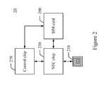
- FIG. 2is a block diagram of a conventional mobile phone supporting an NFC payment function.
- a mobile phone 20 supporting the NFC payment functioncomprises an antenna 210 , an NFC chip 230 , a control chip 270 , and a SIM card 290 .
- Functions of the antenna 210 , the NFC chip 230 , and the control chip 270are respectively similar to those of the antenna 110 , the NFC chip 130 , and the control chip 170 , described above.
- the difference between mobile phone 10 and mobile phone 20is that the SIM card 290 further includes functions of the security chip 150 , in addition to the SIM card 190 functions, which means, SIM card 290 functions as a smart card which integrates functions of the security chip 150 .
- the NFC chip 230communicates with an NFC reader (not shown) according to an identification data of the SIM card 290 to perform the identification procedure.
- the NFC chip 230is connected to the SIM card 290 via an interface implementing a single wire protocol (SWP). Therefore, besides the external battery, the NFC chip 230 can receive electrical power from a wireless signal during interfacing. Even if the battery of the mobile phone 20 is drained, the NFC chip 230 can still operate to communicate with the SIM card 290 via the SWP interface to perform the electronic payment from the power supply generated from the wireless signal.
- power from the wireless signal from the NFC readermay be weak, power obtained by the NFC chip 230 from the wireless signal is rather limited; a rather short communication distance is required between the NFC chip 230 and the NFC reader when electronic power for operating the NFC chip 230 is only provided from the wireless signal. In order to avoid the foregoing problem, power for operating the NFC chip 230 is mainly provided from the battery inside the mobile phone 20 .
- a power supply control apparatus and method thereof applied to a mobile apparatusis needed to reduce power consumption of the mobile apparatus thereby increasing a standby time of the mobile apparatus.
- One object of the present inventionis to provide an electronic power supply control apparatus and method thereof applied to a communication apparatus. Accordingly, through controlling a switch to determine whether to provide power from a battery of a mobile apparatus to the communication apparatus, the mobile apparatus maintains a power-saving mode when electronic payment is not performed to achieve an object of reducing power consumption.
- a power supply control apparatus applied to a communication apparatuscomprises a switch, coupled between a communication circuit and a power supply; and a signal detecting unit, for detecting a wireless signal via electromagnetic induction to correspondingly generate a detection signal that is for controlling the switch to determine whether to provide power to the communication apparatus.
- a power supply control method applied to a communication apparatuscomprises detecting a wireless signal via electromagnetic induction to correspondingly generate a detection signal; and determining whether to provide power to a communication circuit of the communication apparatus according to the detection signal.
- a mobile apparatuscomprises a communication apparatus; a switch, coupled between the communication apparatus and a power supply; and a signal detecting unit, for detecting a wireless signal via electromagnetic induction to correspondingly generate a detection signal that is for controlling the switch to determine whether to provide power to the communication apparatus.
- a power supply control apparatus and method thereof applied to a communication apparatusprovided by the present invention, power is only provided to the communication apparatus when a communication function is performed to reduce power consumption of a battery of a mobile apparatus thereby achieving an object of increasing a standby time of the mobile apparatus.
- FIG. 1is a block diagram of functions of a mobile phone supporting an NFC payment function.
- FIG. 2is a block diagram of functions of a mobile phone supporting an NFC payment function.
- FIG. 3is a block diagram of functions of a power supply control apparatus applied to a communication apparatus in accordance with a first embodiment of the present invention.
- FIG. 4is a flow chart of a power supply control method for the power supply control apparatus in accordance with an embodiment of the present invention.
- FIG. 5is a block diagram of functions of a signal detecting unit in accordance with an embodiment of the present invention.
- FIG. 6is a block diagram of functions of a mobile apparatus using a power supply control apparatus in accordance with an embodiment of the present invention.
- FIG. 7is a block diagram of functions of a signal detecting unit in accordance with an embodiment of the present invention.
- the power control apparatusincludes a switch configured between a battery of a mobile device and an NFC device.
- the power supply control apparatusturns off the switch to stop providing power from the battery of the mobile apparatus to the NFC device.
- the power supply control apparatusUpon detecting the wireless signal transmitted from the NFC reader, the power supply control apparatus turns on the switch to provide power from the battery of the mobile apparatus to the NFC device.
- FIG. 3is a block diagram of functions of a power supply control apparatus applied to a communication device in accordance with a first embodiment of the present invention.
- a power supply control apparatus 310comprises a signal detecting unit 320 and a switch 340 .
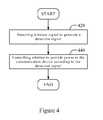
- FIG. 4is a flow chart of a power supply control method for the power supply apparatus in the first embodiment of the present invention.
- a communication deviceis the foregoing NFC device.
- a signal detecting unit 320detects a wireless signal S 0 transmitted from an NFC reader (not shown) via electromagnetic induction to generate a detection signal S 1 .
- the signal detecting unit 320detects the wireless signal S 0 transmitted from the NFC reader, it generates the detection signal S 1 having a value of 1; otherwise, when the signal detecting unit 320 detects that the strength of wireless signal S 0 transmitted from the NFC reader is weakened to a predetermined extent or no wireless signal S 0 is detected, it generates the detection signal S 1 having a value of 0.
- Step 440it is determined whether to provide power Vbat of a battery (not shown) of the mobile apparatus to the communication device 360 according to a status of the switch 340 controlled via the detection signal S 1 . For example, when the value of the detection signal S 1 generated by the signal detecting unit 320 is 1, the switch 340 is turned on to provide power from the battery to the communication device 360 . When the value of the detection signal S 1 detected by the signal detecting unit 320 is 0, the switch 340 is turned off to stop providing power from the battery to the communication apparatus 360 .
- FIG. 5is a block diagram of functions of a signal detecting unit in accordance with an embodiment of the present invention.
- the signal detecting unit 320comprises a signal converting unit 322 , a filter unit 324 , and a coil antenna 329 .
- the coil antenna 329detects whether the wireless signal S 0 is received via electromagnetic induction. When the wireless signal S 0 is detected, the coil antenna 329 generates an alternating current (AC) signal according to the wireless signal S 0 via the induction approach.
- the signal converting unit 322converts the AC signal to a direct current (DC) signal.
- the signal converting unit 322is a rectifier, e.g., a full-bridge circuit or a half-bridge circuit.
- the filter unit 324comprising a capacitor 328 which removes ripple of the DC signal outputted by the signal converting unit 322 via power of the DC signal temporarily stored in the capacitor 328 to generate the detection signal S 1 .
- the coil antenna 329upon detecting the wireless signal S 0 transmitted from the NFC reader (not shown), the coil antenna 329 begins to convert the wireless signal S 0 to the AC signal.
- the signal converting unit 322converts the AC signal to the DC signal for charging the capacitor 328 .
- the filter unit 324outputs the detection signal S 1 having the value of 1, which means that the signal detecting unit 320 has detected the wireless signal S 0 transmitted from the NFC reader.
- the switch 340is turned on according to the detection signal S 1 to provide power from the battery to the communication device 360 . Therefore, the communication device 360 has enough power for communicating with the NFC reader.
- the signal detecting unit 320When the strength of wireless signal S 0 detected by the signal detecting unit 320 is below a predetermined level or the wireless signal S 0 is not detected, the signal detecting unit 320 generates the detection signal S 1 having the value of 0, which means that the detecting unit 320 lost connection from the NFC reader. At this point, the switch 340 turns off accordingly to stop providing power from the battery to the communication device 360 thereby achieving an object of reducing power consumption.
- FIG. 6is a block diagram of functions of a mobile apparatus of a power supply control apparatus in accordance with a second embodiment of the present invention.
- a mobile device 60comprises a controlling unit control device 610 , an SIM card 630 , a battery 670 , and an NFC chip 680 , which comprises a communication device 360 , a power supply control apparatus 620 and a power generating unit 650 .
- the power supply control apparatus 620comprises a signal detecting unit 320 , a switch 340 , and an OR gate 690 for receiving signals from the controlling unit 610 (Vce) and signal detecting unit 320 (S 1 ) and generating an output switch signal SW, sent to switch 340 , based on these signal inputs.
- the communication device 360 and the power supply control apparatus 620are integrated in the NFC chip 680 , in practice, the communication apparatus 360 and the power supply control apparatus 620 can also be configured in different chips.
- a control signal Vce for controlling the switch 340is implemented to determine whether or not to provide power from the battery 670 to the communication apparatus 360 .
- the usercontrols the control device 610 via a user interface (UI) (not shown) of the mobile apparatus 60 to set a value of the control signal Vce as 0, so that the mobile apparatus 60 enters a power-saving mode in which power is no longer being provided from the battery 670 to the communication device 360 when the communication apparatus 360 does not operate thereby achieving the object of the reducing power consumption of mobile apparatus 60 .
- the OR gate 690generates a switch signal SW according to the control signal Vce and the detection signal S 1 to control a status of the switch 340 thereby achieving an object of controlling whether to provide power from the battery 670 to the communication apparatus 360 .
- the useroperates the UI to control the control device 610 to determine whether to set the mobile apparatus 60 as being in the power-saving mode.
- the control apparatus 610defines the value of the control signal Vice as 0 to stop providing power from the battery 670 to the communication device 360 when the wireless signal S 0 is not detected, so that the communication device stops operating to save power consumption.
- the signal detecting unit 320does not detect the wireless signal S 0
- the signal detecting unit 320generates the detection signal S 1 having the value of 0.
- two inputs value of the OR gate 690are both 0, such that the OR gate 690 outputs the switch signal SW having the value of 0 to turn off the switch 340 . Accordingly the communication device 360 cannot obtain power of the battery 670 , reducing power consumption.
- the signal detecting unit 320detects the wireless signal S 0 transmitted from the NFC reader via electromagnetic induction to generate the detection signal of value of 1, so that the switch signal SW outputted by the OR gate 690 also has the value of 1 to turn on the switch 340 , and thus power is provided from the battery 670 to the communication device 360 . Therefore, the communication device has enough power for communicating with the SIM card 630 and the NFC reader to perform the electronic payment.
- the signal detecting unit 320detects the wireless signal S 0 , the detection signal S 1 having the value of 1 is generated via the signal detecting unit 320 to turn on the switch 340 , so that the battery 670 provides power to operate the communication device 360 for the electronic payment.
- the signal detecting unit 320detects the wireless signal S 0 transmitted from the NFC reader
- the signal detecting unit 320generates the detection signal S 1 having the value of 1 to turn on the switch 340 , so that the communication device 360 can communicate with the NFC reader using power of the battery 670 . Therefore, according to the present invention, while standby time of the mobile apparatus 60 can be longer, the communication apparatus 360 still can directly get power from battery 670 (if it still has power) to perform a long-distance and stable communication when the mobile apparatus 60 is in the turn-off status. When the battery 670 runs out of power, the mobile apparatus 60 receives power of the wireless signal S 0 via the power generating unit 650 to provide power to the communication apparatus 360 for communication.
- FIG. 7is a function block diagram of a signal detecting unit 320 in accordance with an embodiment of the present invention.
- the signal detecting unit 320comprises a signal converting unit 322 , a filter unit 324 , a discharge indication circuit 326 , a switch 327 , and a coil antenna 329 .
- the filter unit 324comprises a capacitor 328 .
- the discharge indicating circuit 326comprises a rectifier 321 , a capacitor 323 , and a discharge unit 325 .
- the switch 327 coupled between the capacitor 328 and groundis controlled by an indicating signal S 2 . Operations of the signal converting unit 322 , the filter unit 324 , and the coil antenna 329 are similar to those of the foregoing embodiments, and shall not be described for brevity.
- the coil antenna 329detects the wireless signal S 0 , and generates an AC signal according to the wireless signal S 0 via electromagnetic induction.
- the signal converting unit 322converts the AC signal to a DC signal.
- the capacitor 328charges the DC signal to a predetermined voltage level and maintains at the predetermined voltage level.
- the discharge indicating circuit 326detects whether the wireless signal S 0 is disappearing or weakening thereby determining whether the mobile apparatus is getting away from the NFC reader. When the discharge indication circuit 326 detects that the wireless signal S 0 is weakened to a predetermined level or is not present, an indicating signal S 2 is generated to turn on the switch 327 so as to discharge the capacitor.
- the rectifier 321detects whether the wireless signal S 0 is received via the coil antenna 329 .
- the coil antenna 329detects the wireless signal S 0
- the AC signalis converted to the DC signal.
- the rectifier 321may be a full-bridge circuit or a half-bridge circuit, as an example, but is not limited to these specific components.
- the rectifier 321converts the AC signal generated by the coil antenna 329 to the DC signal, and starts charging the capacitor 323 .
- the discharge unit 325discharges power stored in the capacitor 323 .
- the rectifier 321continuously receives AC signals, i.e., the rectifier 321 continuously charges the capacitor 323 . Since a charging speed of the capacitor 323 is faster than a discharging speed of the discharge unit 325 , power stored in the capacitor 323 cannot be completely discharged by the discharge unit 325 , such that the capacitor 323 maintains at a predetermined voltage level.
- the indicating signal S 2indicates to turn off the switch 327 , and the capacitor 328 is not discharged, so that the filter unit 324 generates the detection signal S 1 having the value of 1, meaning that the signal detecting unit 320 actually receives the wireless signal S 0 .
- the signal detecting unit 320goes away from the NFC reader, meaning that the rectifier 321 cannot receive AC signals or the AC signals are weakened to an extent, and a speed of charging the capacitor 323 by the rectifier 321 is slower than that of discharging the capacitor 323 by the discharge unit 325 , electric power temporarily stored in the capacitor 323 is completely discharged by the discharge unit 325 .
- the indicating signal S 2indicates to turn on the switch 327 so as to discharge power temporarily stored in the capacitor 328 , so that the filter unit 324 can generate the detection signal S 1 having the value of 0, which means that the signal detecting unit 320 leaves from the NFC reader.
- a power supply control apparatus and method thereof applied to a communication apparatusare provided.
- the communication apparatus of the mobile apparatusThrough controlling a switch to determine whether to provide power from a battery of a mobile apparatus to a communication apparatus, the communication apparatus of the mobile apparatus only starts operating when communication is performed. That is, according to the present invention, the mobile apparatus, having an NFC function, is set as in a power-saving mode when electronic payment is not performed. Hence, the mobile device can have a less power consumption and longer standby time.
Landscapes
- Engineering & Computer Science (AREA)
- Computer Networks & Wireless Communication (AREA)
- Signal Processing (AREA)
- Computer Hardware Design (AREA)
- Microelectronics & Electronic Packaging (AREA)
- Physics & Mathematics (AREA)
- General Physics & Mathematics (AREA)
- Theoretical Computer Science (AREA)
- Telephone Function (AREA)
- Near-Field Transmission Systems (AREA)
Abstract
Description
Claims (14)
Applications Claiming Priority (3)
| Application Number | Priority Date | Filing Date | Title |
|---|---|---|---|
| TW99124926A | 2010-07-28 | ||
| TW099124926 | 2010-07-28 | ||
| TW099124926ATWI451238B (en) | 2010-07-28 | 2010-07-28 | Power control apparatus and method thereof and mobile apparatus using it |
Publications (2)
| Publication Number | Publication Date |
|---|---|
| US20120028575A1 US20120028575A1 (en) | 2012-02-02 |
| US8583075B2true US8583075B2 (en) | 2013-11-12 |
Family
ID=45527217
Family Applications (1)
| Application Number | Title | Priority Date | Filing Date |
|---|---|---|---|
| US13/097,920Active2031-09-14US8583075B2 (en) | 2010-07-28 | 2011-04-29 | Power supply control apparatus and method thereof and mobile apparatus using the same |
Country Status (2)
| Country | Link |
|---|---|
| US (1) | US8583075B2 (en) |
| TW (1) | TWI451238B (en) |
Cited By (3)
| Publication number | Priority date | Publication date | Assignee | Title |
|---|---|---|---|---|
| US20120322381A1 (en)* | 2010-03-03 | 2012-12-20 | Nec Corporation | Wireless communication apparatus |
| US20140141844A1 (en)* | 2012-11-16 | 2014-05-22 | Prasad Vara Venkata Satya Golla | Mobile terminal |
| US9031505B2 (en)* | 2009-09-07 | 2015-05-12 | Broadcom Europe Limited | Filtering a single wire protocol (SWP) current signal to be provided to a near field communications (NFC) device |
Families Citing this family (69)
| Publication number | Priority date | Publication date | Assignee | Title |
|---|---|---|---|---|
| US8989705B1 (en) | 2009-06-18 | 2015-03-24 | Sprint Communications Company L.P. | Secure placement of centralized media controller application in mobile access terminal |
| US8718546B2 (en)* | 2010-08-16 | 2014-05-06 | Blackberry Limited | Near-field communication (NFC) system providing low power peer-to-peer recognition mode and related methods |
| CN103299317B (en) | 2010-12-15 | 2016-09-07 | 意法半导体(鲁塞)公司 | For the method and apparatus managing the information exchange between major component and one group of at least two auxiliary element |
| US10088431B2 (en) | 2011-05-17 | 2018-10-02 | Gii Acquisition, Llc | Method and system for optically inspecting headed manufactured parts |
| US10094785B2 (en) | 2011-05-17 | 2018-10-09 | Gii Acquisition, Llc | Method and system for optically inspecting headed manufactured parts |
| US8712407B1 (en)* | 2012-04-05 | 2014-04-29 | Sprint Communications Company L.P. | Multiple secure elements in mobile electronic device with near field communication capability |
| US9027102B2 (en) | 2012-05-11 | 2015-05-05 | Sprint Communications Company L.P. | Web server bypass of backend process on near field communications and secure element chips |
| US8862181B1 (en) | 2012-05-29 | 2014-10-14 | Sprint Communications Company L.P. | Electronic purchase transaction trust infrastructure |
| US9282898B2 (en) | 2012-06-25 | 2016-03-15 | Sprint Communications Company L.P. | End-to-end trusted communications infrastructure |
| US9066230B1 (en) | 2012-06-27 | 2015-06-23 | Sprint Communications Company L.P. | Trusted policy and charging enforcement function |
| US8649770B1 (en) | 2012-07-02 | 2014-02-11 | Sprint Communications Company, L.P. | Extended trusted security zone radio modem |
| US8667607B2 (en) | 2012-07-24 | 2014-03-04 | Sprint Communications Company L.P. | Trusted security zone access to peripheral devices |
| US8863252B1 (en) | 2012-07-25 | 2014-10-14 | Sprint Communications Company L.P. | Trusted access to third party applications systems and methods |
| US9183412B2 (en) | 2012-08-10 | 2015-11-10 | Sprint Communications Company L.P. | Systems and methods for provisioning and using multiple trusted security zones on an electronic device |
| JP6051681B2 (en)* | 2012-08-24 | 2016-12-27 | ソニー株式会社 | Information processing apparatus, information processing method, and program |
| US9215180B1 (en) | 2012-08-25 | 2015-12-15 | Sprint Communications Company L.P. | File retrieval in real-time brokering of digital content |
| US8954588B1 (en) | 2012-08-25 | 2015-02-10 | Sprint Communications Company L.P. | Reservations in real-time brokering of digital content delivery |
| US9015068B1 (en) | 2012-08-25 | 2015-04-21 | Sprint Communications Company L.P. | Framework for real-time brokering of digital content delivery |
| US8752140B1 (en) | 2012-09-11 | 2014-06-10 | Sprint Communications Company L.P. | System and methods for trusted internet domain networking |
| CN103064816B (en)* | 2013-01-07 | 2016-04-06 | 华为终端有限公司 | SIM card hot plug is protected and SIM card shutdown in place is swiped the card method, terminal |
| US9161227B1 (en) | 2013-02-07 | 2015-10-13 | Sprint Communications Company L.P. | Trusted signaling in long term evolution (LTE) 4G wireless communication |
| US9578664B1 (en) | 2013-02-07 | 2017-02-21 | Sprint Communications Company L.P. | Trusted signaling in 3GPP interfaces in a network function virtualization wireless communication system |
| US9104840B1 (en) | 2013-03-05 | 2015-08-11 | Sprint Communications Company L.P. | Trusted security zone watermark |
| US8881977B1 (en) | 2013-03-13 | 2014-11-11 | Sprint Communications Company L.P. | Point-of-sale and automated teller machine transactions using trusted mobile access device |
| US9613208B1 (en) | 2013-03-13 | 2017-04-04 | Sprint Communications Company L.P. | Trusted security zone enhanced with trusted hardware drivers |
| US9049186B1 (en) | 2013-03-14 | 2015-06-02 | Sprint Communications Company L.P. | Trusted security zone re-provisioning and re-use capability for refurbished mobile devices |
| US9049013B2 (en) | 2013-03-14 | 2015-06-02 | Sprint Communications Company L.P. | Trusted security zone containers for the protection and confidentiality of trusted service manager data |
| US9191388B1 (en) | 2013-03-15 | 2015-11-17 | Sprint Communications Company L.P. | Trusted security zone communication addressing on an electronic device |
| US8984592B1 (en) | 2013-03-15 | 2015-03-17 | Sprint Communications Company L.P. | Enablement of a trusted security zone authentication for remote mobile device management systems and methods |
| US9374363B1 (en) | 2013-03-15 | 2016-06-21 | Sprint Communications Company L.P. | Restricting access of a portable communication device to confidential data or applications via a remote network based on event triggers generated by the portable communication device |
| US9021585B1 (en) | 2013-03-15 | 2015-04-28 | Sprint Communications Company L.P. | JTAG fuse vulnerability determination and protection using a trusted execution environment |
| US9171243B1 (en) | 2013-04-04 | 2015-10-27 | Sprint Communications Company L.P. | System for managing a digest of biographical information stored in a radio frequency identity chip coupled to a mobile communication device |
| US9324016B1 (en) | 2013-04-04 | 2016-04-26 | Sprint Communications Company L.P. | Digest of biographical information for an electronic device with static and dynamic portions |
| US9454723B1 (en) | 2013-04-04 | 2016-09-27 | Sprint Communications Company L.P. | Radio frequency identity (RFID) chip electrically and communicatively coupled to motherboard of mobile communication device |
| US9838869B1 (en) | 2013-04-10 | 2017-12-05 | Sprint Communications Company L.P. | Delivering digital content to a mobile device via a digital rights clearing house |
| US9443088B1 (en) | 2013-04-15 | 2016-09-13 | Sprint Communications Company L.P. | Protection for multimedia files pre-downloaded to a mobile device |
| US9069952B1 (en) | 2013-05-20 | 2015-06-30 | Sprint Communications Company L.P. | Method for enabling hardware assisted operating system region for safe execution of untrusted code using trusted transitional memory |
| US9560519B1 (en) | 2013-06-06 | 2017-01-31 | Sprint Communications Company L.P. | Mobile communication device profound identity brokering framework |
| US8844833B1 (en) | 2013-06-10 | 2014-09-30 | Compal Electronics, Inc. | Portable electronic system, accessory for electronic device, and method for activating application of electronic device |
| US9183606B1 (en) | 2013-07-10 | 2015-11-10 | Sprint Communications Company L.P. | Trusted processing location within a graphics processing unit |
| US9208339B1 (en) | 2013-08-12 | 2015-12-08 | Sprint Communications Company L.P. | Verifying Applications in Virtual Environments Using a Trusted Security Zone |
| US9185626B1 (en) | 2013-10-29 | 2015-11-10 | Sprint Communications Company L.P. | Secure peer-to-peer call forking facilitated by trusted 3rd party voice server provisioning |
| US9191522B1 (en) | 2013-11-08 | 2015-11-17 | Sprint Communications Company L.P. | Billing varied service based on tier |
| US9161325B1 (en) | 2013-11-20 | 2015-10-13 | Sprint Communications Company L.P. | Subscriber identity module virtualization |
| US9118655B1 (en) | 2014-01-24 | 2015-08-25 | Sprint Communications Company L.P. | Trusted display and transmission of digital ticket documentation |
| JP5703452B1 (en)* | 2014-03-06 | 2015-04-22 | パナソニックIpマネジメント株式会社 | Information processing apparatus and information processing method |
| US9226145B1 (en) | 2014-03-28 | 2015-12-29 | Sprint Communications Company L.P. | Verification of mobile device integrity during activation |
| US9230085B1 (en) | 2014-07-29 | 2016-01-05 | Sprint Communications Company L.P. | Network based temporary trust extension to a remote or mobile device enabled via specialized cloud services |
| CN107005282A (en)* | 2014-11-18 | 2017-08-01 | Mc10股份有限公司 | The systems, devices and methods activated for electronic installation |
| TWI557552B (en)* | 2014-12-12 | 2016-11-11 | 廣達電腦股份有限公司 | Sensing system |
| US9779232B1 (en) | 2015-01-14 | 2017-10-03 | Sprint Communications Company L.P. | Trusted code generation and verification to prevent fraud from maleficent external devices that capture data |
| US9838868B1 (en) | 2015-01-26 | 2017-12-05 | Sprint Communications Company L.P. | Mated universal serial bus (USB) wireless dongles configured with destination addresses |
| TWI669230B (en)* | 2015-02-04 | 2019-08-21 | 英屬開曼群島商鴻騰精密科技股份有限公司 | Powerless smart key, method and system for unlocking entrance guardusing same |
| TWI669229B (en)* | 2015-02-04 | 2019-08-21 | 英屬開曼群島商鴻騰精密科技股份有限公司 | Method and system for unlocking vehicle |
| WO2016134306A1 (en) | 2015-02-20 | 2016-08-25 | Mc10, Inc. | Automated detection and configuration of wearable devices based on on-body status, location, and/or orientation |
| US9473945B1 (en) | 2015-04-07 | 2016-10-18 | Sprint Communications Company L.P. | Infrastructure for secure short message transmission |
| US9819679B1 (en) | 2015-09-14 | 2017-11-14 | Sprint Communications Company L.P. | Hardware assisted provenance proof of named data networking associated to device data, addresses, services, and servers |
| US10282719B1 (en) | 2015-11-12 | 2019-05-07 | Sprint Communications Company L.P. | Secure and trusted device-based billing and charging process using privilege for network proxy authentication and audit |
| US9817992B1 (en) | 2015-11-20 | 2017-11-14 | Sprint Communications Company Lp. | System and method for secure USIM wireless network access |
| CN109310340A (en) | 2016-04-19 | 2019-02-05 | Mc10股份有限公司 | Method and system for measuring sweat |
| US9967001B2 (en)* | 2016-07-25 | 2018-05-08 | Verily Life Sciences Llc | Systems and methods for passive radio enabled power gating for a body mountable device |
| US10447347B2 (en) | 2016-08-12 | 2019-10-15 | Mc10, Inc. | Wireless charger and high speed data off-loader |
| KR20180037473A (en)* | 2016-10-04 | 2018-04-12 | 삼성전자주식회사 | Mobile payment method, electronic device and external payment device therefor |
| FR3062937A1 (en)* | 2017-02-14 | 2018-08-17 | Stmicroelectronics (Rousset) Sas | ACTIVATION OF AN NFC DEVICE |
| US10499249B1 (en) | 2017-07-11 | 2019-12-03 | Sprint Communications Company L.P. | Data link layer trust signaling in communication network |
| US11426101B2 (en) | 2018-07-09 | 2022-08-30 | Verily Life Sciences Llc | Systems and methods for sensors with multimode wireless communications and for enabling NFC communications with a wearable biosensor |
| US11038555B2 (en) | 2018-08-06 | 2021-06-15 | Verily Life Sciences Llc | Systems and methods for enabling NFC communications with a wearable biosensor |
| TWI676870B (en)* | 2018-10-19 | 2019-11-11 | 巨擘科技股份有限公司 | Wristwatch and power saving method thereof |
| KR102594118B1 (en)* | 2019-02-22 | 2023-10-25 | 삼성전자주식회사 | A wireless communication device for detecting card |
Citations (7)
| Publication number | Priority date | Publication date | Assignee | Title |
|---|---|---|---|---|
| US6427065B1 (en)* | 1996-09-13 | 2002-07-30 | Hitachi, Ltd. | Power transmission system, IC card and information communication system using IC card |
| US6807400B2 (en)* | 2001-04-20 | 2004-10-19 | Texas Instruments Deutschland Gmbh | Batteryless transponder |
| US20060202804A1 (en)* | 2005-03-09 | 2006-09-14 | Intermec Ip Corp., | Sleep command for active RF tags to prolong battery life |
| US20070015465A1 (en)* | 2003-02-14 | 2007-01-18 | Olivier Giroud | System comprising controlled-supply bluetooth communication module, radio communication assembly, methods and readers |
| US20090231179A1 (en)* | 2007-12-18 | 2009-09-17 | Maquet Gmbh & Co. Kg | Arrangement, system and method for the wireless control of an apparatus |
| US20090291635A1 (en)* | 2008-05-26 | 2009-11-26 | Commissariat A L'energie Atomique | Radio-frequency communication device, system and method |
| US8063746B2 (en)* | 2006-03-31 | 2011-11-22 | Assa Abloy Ab | Transponder detector for an RFID system generating a progression of detection signals |
Family Cites Families (1)
| Publication number | Priority date | Publication date | Assignee | Title |
|---|---|---|---|---|
| US8884468B2 (en)* | 2007-12-21 | 2014-11-11 | Access Business Group International Llc | Circuitry for inductive power transfer |
- 2010
- 2010-07-28TWTW099124926Apatent/TWI451238B/ennot_activeIP Right Cessation
- 2011
- 2011-04-29USUS13/097,920patent/US8583075B2/enactiveActive
Patent Citations (7)
| Publication number | Priority date | Publication date | Assignee | Title |
|---|---|---|---|---|
| US6427065B1 (en)* | 1996-09-13 | 2002-07-30 | Hitachi, Ltd. | Power transmission system, IC card and information communication system using IC card |
| US6807400B2 (en)* | 2001-04-20 | 2004-10-19 | Texas Instruments Deutschland Gmbh | Batteryless transponder |
| US20070015465A1 (en)* | 2003-02-14 | 2007-01-18 | Olivier Giroud | System comprising controlled-supply bluetooth communication module, radio communication assembly, methods and readers |
| US20060202804A1 (en)* | 2005-03-09 | 2006-09-14 | Intermec Ip Corp., | Sleep command for active RF tags to prolong battery life |
| US8063746B2 (en)* | 2006-03-31 | 2011-11-22 | Assa Abloy Ab | Transponder detector for an RFID system generating a progression of detection signals |
| US20090231179A1 (en)* | 2007-12-18 | 2009-09-17 | Maquet Gmbh & Co. Kg | Arrangement, system and method for the wireless control of an apparatus |
| US20090291635A1 (en)* | 2008-05-26 | 2009-11-26 | Commissariat A L'energie Atomique | Radio-frequency communication device, system and method |
Cited By (5)
| Publication number | Priority date | Publication date | Assignee | Title |
|---|---|---|---|---|
| US9031505B2 (en)* | 2009-09-07 | 2015-05-12 | Broadcom Europe Limited | Filtering a single wire protocol (SWP) current signal to be provided to a near field communications (NFC) device |
| US20120322381A1 (en)* | 2010-03-03 | 2012-12-20 | Nec Corporation | Wireless communication apparatus |
| US8903310B2 (en)* | 2010-03-03 | 2014-12-02 | Nec Corporation | Wireless communication apparatus |
| US20140141844A1 (en)* | 2012-11-16 | 2014-05-22 | Prasad Vara Venkata Satya Golla | Mobile terminal |
| US9414309B2 (en)* | 2012-11-16 | 2016-08-09 | Intel Deutschland Gmbh | Mobile terminal |
Also Published As
| Publication number | Publication date |
|---|---|
| US20120028575A1 (en) | 2012-02-02 |
| TWI451238B (en) | 2014-09-01 |
| TW201205270A (en) | 2012-02-01 |
Similar Documents
| Publication | Publication Date | Title |
|---|---|---|
| US8583075B2 (en) | Power supply control apparatus and method thereof and mobile apparatus using the same | |
| US7652578B2 (en) | Detection apparatus and method for near field communication devices | |
| US9070059B2 (en) | Portable object with self switching device | |
| EP2933757B1 (en) | Communication device, communication method, integrated circuit, and electronic instrument | |
| KR100968071B1 (en) | How to perform a traffic card function with a mobile communication terminal having an authentication information card and a near field communication chip | |
| US7472834B2 (en) | Dual-mode smart card | |
| US20230268776A1 (en) | Wireless communication charging circuit system | |
| CN102347626B (en) | Power supply control device and method as well as mobile device using same | |
| US11995499B2 (en) | IC card and IC card system | |
| US10074992B2 (en) | Battery device, battery management method, and electronic apparatus | |
| US9219519B2 (en) | Proximity wireless transmission/reception device | |
| US9431847B2 (en) | Communication device, communication method, battery device, and electronic apparatus | |
| US11012119B2 (en) | NFC arrangement | |
| CN105512716A (en) | Multifunctional IC card | |
| US12039387B2 (en) | IC card and IC card system | |
| JP2009094883A (en) | Auxiliary power system for cellular phone | |
| JP3838901B2 (en) | Contact / contactless IC card | |
| KR200324928Y1 (en) | Card Reader Switched by Capacitive Sensor | |
| US12282374B2 (en) | Electronic card | |
| US20170206386A1 (en) | Smart objects | |
| EP1649712A1 (en) | Circuit for a data carrier, which circuit can be switched from an energy-saving processing mode to a normal-consumption processing mode | |
| KR100737560B1 (en) | Contactless battery charger | |
| JP2016139365A (en) | Electronic device with display function | |
| JP2017111588A (en) | Non-contact IC card |
Legal Events
| Date | Code | Title | Description |
|---|---|---|---|
| AS | Assignment | Owner name:MSTAR SEMICONDUCTOR, INC., TAIWAN Free format text:ASSIGNMENT OF ASSIGNORS INTEREST;ASSIGNORS:CHEN, CHIEN-SHENG;CHIANG, CHIEN-SHAN;REEL/FRAME:026203/0786 Effective date:20110421 | |
| FEPP | Fee payment procedure | Free format text:PAYOR NUMBER ASSIGNED (ORIGINAL EVENT CODE: ASPN); ENTITY STATUS OF PATENT OWNER: LARGE ENTITY | |
| STCF | Information on status: patent grant | Free format text:PATENTED CASE | |
| FPAY | Fee payment | Year of fee payment:4 | |
| AS | Assignment | Owner name:MEDIATEK INC., TAIWAN Free format text:MERGER;ASSIGNOR:MSTAR SEMICONDUCTOR, INC.;REEL/FRAME:052931/0468 Effective date:20190115 | |
| AS | Assignment | Owner name:XUESHAN TECHNOLOGIES INC., CANADA Free format text:ASSIGNMENT OF ASSIGNORS INTEREST;ASSIGNOR:MEDIATEK INC.;REEL/FRAME:055486/0870 Effective date:20201223 | |
| MAFP | Maintenance fee payment | Free format text:PAYMENT OF MAINTENANCE FEE, 8TH YEAR, LARGE ENTITY (ORIGINAL EVENT CODE: M1552); ENTITY STATUS OF PATENT OWNER: LARGE ENTITY Year of fee payment:8 | |
| MAFP | Maintenance fee payment | Free format text:PAYMENT OF MAINTENANCE FEE, 12TH YEAR, LARGE ENTITY (ORIGINAL EVENT CODE: M1553); ENTITY STATUS OF PATENT OWNER: LARGE ENTITY Year of fee payment:12 |