US8582232B2 - Heat assisted spindle motor - Google Patents
Heat assisted spindle motorDownload PDFInfo
- Publication number
- US8582232B2 US8582232B2US12/012,883US1288308AUS8582232B2US 8582232 B2US8582232 B2US 8582232B2US 1288308 AUS1288308 AUS 1288308AUS 8582232 B2US8582232 B2US 8582232B2
- Authority
- US
- United States
- Prior art keywords
- current
- spindle motor
- time interval
- predetermined time
- disk
- Prior art date
- Legal status (The legal status is an assumption and is not a legal conclusion. Google has not performed a legal analysis and makes no representation as to the accuracy of the status listed.)
- Expired - Fee Related, expires
Links
Images

Classifications
- G—PHYSICS
- G11—INFORMATION STORAGE
- G11B—INFORMATION STORAGE BASED ON RELATIVE MOVEMENT BETWEEN RECORD CARRIER AND TRANSDUCER
- G11B33/00—Constructional parts, details or accessories not provided for in the other groups of this subclass
- G11B33/14—Reducing influence of physical parameters, e.g. temperature change, moisture, dust
- G11B33/1406—Reducing the influence of the temperature
- G11B33/144—Reducing the influence of the temperature by detection, control, regulation of the temperature
- F—MECHANICAL ENGINEERING; LIGHTING; HEATING; WEAPONS; BLASTING
- F16—ENGINEERING ELEMENTS AND UNITS; GENERAL MEASURES FOR PRODUCING AND MAINTAINING EFFECTIVE FUNCTIONING OF MACHINES OR INSTALLATIONS; THERMAL INSULATION IN GENERAL
- F16C—SHAFTS; FLEXIBLE SHAFTS; ELEMENTS OR CRANKSHAFT MECHANISMS; ROTARY BODIES OTHER THAN GEARING ELEMENTS; BEARINGS
- F16C17/00—Sliding-contact bearings for exclusively rotary movement
- F16C17/12—Sliding-contact bearings for exclusively rotary movement characterised by features not related to the direction of the load
- F16C17/24—Sliding-contact bearings for exclusively rotary movement characterised by features not related to the direction of the load with devices affected by abnormal or undesired positions, e.g. for preventing overheating, for safety
- F16C17/243—Sliding-contact bearings for exclusively rotary movement characterised by features not related to the direction of the load with devices affected by abnormal or undesired positions, e.g. for preventing overheating, for safety related to temperature and heat, e.g. for preventing overheating
- G—PHYSICS
- G11—INFORMATION STORAGE
- G11B—INFORMATION STORAGE BASED ON RELATIVE MOVEMENT BETWEEN RECORD CARRIER AND TRANSDUCER
- G11B19/00—Driving, starting, stopping record carriers not specifically of filamentary or web form, or of supports therefor; Control thereof; Control of operating function ; Driving both disc and head
- G11B19/02—Control of operating function, e.g. switching from recording to reproducing
- G11B19/04—Arrangements for preventing, inhibiting, or warning against double recording on the same blank or against other recording or reproducing malfunctions
- G11B19/046—Detection or prevention or problems due to temperature
- G—PHYSICS
- G11—INFORMATION STORAGE
- G11B—INFORMATION STORAGE BASED ON RELATIVE MOVEMENT BETWEEN RECORD CARRIER AND TRANSDUCER
- G11B19/00—Driving, starting, stopping record carriers not specifically of filamentary or web form, or of supports therefor; Control thereof; Control of operating function ; Driving both disc and head
- G11B19/20—Driving; Starting; Stopping; Control thereof
- G11B19/2054—Spindle motor power-up sequences
- G—PHYSICS
- G11—INFORMATION STORAGE
- G11B—INFORMATION STORAGE BASED ON RELATIVE MOVEMENT BETWEEN RECORD CARRIER AND TRANSDUCER
- G11B25/00—Apparatus characterised by the shape of record carrier employed but not specific to the method of recording or reproducing, e.g. dictating apparatus; Combinations of such apparatus
- G11B25/04—Apparatus characterised by the shape of record carrier employed but not specific to the method of recording or reproducing, e.g. dictating apparatus; Combinations of such apparatus using flat record carriers, e.g. disc, card
- G11B25/043—Apparatus characterised by the shape of record carrier employed but not specific to the method of recording or reproducing, e.g. dictating apparatus; Combinations of such apparatus using flat record carriers, e.g. disc, card using rotating discs
- H—ELECTRICITY
- H02—GENERATION; CONVERSION OR DISTRIBUTION OF ELECTRIC POWER
- H02K—DYNAMO-ELECTRIC MACHINES
- H02K15/00—Processes or apparatus specially adapted for manufacturing, assembling, maintaining or repairing of dynamo-electric machines
- H02K15/12—Impregnating, moulding insulation, heating or drying of windings, stators, rotors or machines
- H02K15/125—Heating or drying of machines in operational state, e.g. standstill heating
- H—ELECTRICITY
- H02—GENERATION; CONVERSION OR DISTRIBUTION OF ELECTRIC POWER
- H02K—DYNAMO-ELECTRIC MACHINES
- H02K5/00—Casings; Enclosures; Supports
- H02K5/04—Casings or enclosures characterised by the shape, form or construction thereof
- H02K5/16—Means for supporting bearings, e.g. insulating supports or means for fitting bearings in the bearing-shields
- H02K5/163—Means for supporting bearings, e.g. insulating supports or means for fitting bearings in the bearing-shields radially supporting the rotary shaft at only one end of the rotor
- H—ELECTRICITY
- H02—GENERATION; CONVERSION OR DISTRIBUTION OF ELECTRIC POWER
- H02K—DYNAMO-ELECTRIC MACHINES
- H02K7/00—Arrangements for handling mechanical energy structurally associated with dynamo-electric machines, e.g. structural association with mechanical driving motors or auxiliary dynamo-electric machines
- H02K7/08—Structural association with bearings
- H02K7/085—Structural association with bearings radially supporting the rotary shaft at only one end of the rotor
- F—MECHANICAL ENGINEERING; LIGHTING; HEATING; WEAPONS; BLASTING
- F16—ENGINEERING ELEMENTS AND UNITS; GENERAL MEASURES FOR PRODUCING AND MAINTAINING EFFECTIVE FUNCTIONING OF MACHINES OR INSTALLATIONS; THERMAL INSULATION IN GENERAL
- F16C—SHAFTS; FLEXIBLE SHAFTS; ELEMENTS OR CRANKSHAFT MECHANISMS; ROTARY BODIES OTHER THAN GEARING ELEMENTS; BEARINGS
- F16C17/00—Sliding-contact bearings for exclusively rotary movement
- F16C17/10—Sliding-contact bearings for exclusively rotary movement for both radial and axial load
- F16C17/102—Sliding-contact bearings for exclusively rotary movement for both radial and axial load with grooves in the bearing surface to generate hydrodynamic pressure
- F16C17/107—Sliding-contact bearings for exclusively rotary movement for both radial and axial load with grooves in the bearing surface to generate hydrodynamic pressure with at least one surface for radial load and at least one surface for axial load
- F—MECHANICAL ENGINEERING; LIGHTING; HEATING; WEAPONS; BLASTING
- F16—ENGINEERING ELEMENTS AND UNITS; GENERAL MEASURES FOR PRODUCING AND MAINTAINING EFFECTIVE FUNCTIONING OF MACHINES OR INSTALLATIONS; THERMAL INSULATION IN GENERAL
- F16C—SHAFTS; FLEXIBLE SHAFTS; ELEMENTS OR CRANKSHAFT MECHANISMS; ROTARY BODIES OTHER THAN GEARING ELEMENTS; BEARINGS
- F16C2370/00—Apparatus relating to physics, e.g. instruments
- F16C2370/12—Hard disk drives or the like
- H—ELECTRICITY
- H02—GENERATION; CONVERSION OR DISTRIBUTION OF ELECTRIC POWER
- H02K—DYNAMO-ELECTRIC MACHINES
- H02K7/00—Arrangements for handling mechanical energy structurally associated with dynamo-electric machines, e.g. structural association with mechanical driving motors or auxiliary dynamo-electric machines
- H02K7/14—Structural association with mechanical loads, e.g. with hand-held machine tools or fans
Definitions
- the present inventionrelates to preheating a spindle motor of a hard disk drive.
- Hard disk drivescontain a plurality of magnetic heads that are coupled to rotating disks.
- the headswrite and read information by magnetizing and sensing the magnetic fields of the disk surfaces.
- Each headis attached to a flexure arm to create a subassembly commonly referred to as a head gimbal assembly (“HGA”).
- HGAhead gimbal assembly
- the HGA'sare suspended from an actuator arm.
- the actuator armhas a voice coil motor that can move the heads across the surfaces of the disks.
- the disksare rotated by a spindle motor of the drive. Rotation of the disks creates an air flow within the disk drive.
- Each headhas an air bearing surface that cooperates with the air flow to create an air bearing between the head and the adjacent disk surface. The air bearing eliminates or minimizes the mechanical wear between the head and the disk. Rotation of the disk also allows for access to data located across the disk surfaces.
- Hard disk drivesmay be used in systems, such as automobiles, that are exposed to relatively low temperatures.
- automobilesmay include a disk drive. Automobiles can be exposed to extreme ambient temperatures.
- the spindle motor of a disk drivetypically has some type of fluid bearing. At very low temperatures the fluid bearing may be to stiff to allow for proper actuation of the spindle motor.
- a hard disk drivethat includes a spindle motor to rotate a disk of the drive.
- the disk drivealso includes a circuit that provides current to the spindle motor to heat the motor before the disk is rotated.
- FIG. 1is a top view of an embodiment of a hard disk drive
- FIG. 2is a top enlarged view of a head of the hard disk drive
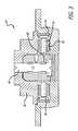
- FIG. 3is a side view of a spindle motor of the disk drive
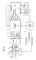
- FIG. 4is a schematic of an electrical circuit for the hard disk drive.
- a hard disk drivewith a spindle motor that rotates a disk.
- a currentcan be provided to the spindle motor to heat the motor.
- a DC currentcan be provided to the spindle motor.
- the current flowing through the spindle motor coilgenerates heat.
- the currentcan be provided for a predetermined time interval to sufficiently heat the spindle motor so that the fluid bearings of the motor can operate.
- the currentis terminated and then an AC current is provided to the spindle motor to cause motor rotation.
- FIG. 1shows an embodiment of a hard disk drive 10 of the present invention.
- the disk drive 10may include one or more magnetic disks 12 that are rotated by a spindle motor 14 .
- the spindle motor 14may be mounted to a base plate 16 .
- the disk drive 10may further have a cover 18 that encloses the disks 12 .
- the disk drive 10may include a plurality of heads 20 located adjacent to the disks 12 . As shown in FIG. 2 the heads 20 may have separate write 22 and read elements 24 .
- the write element 22magnetizes the disk 12 to write data.
- the read element 24senses the magnetic fields of the disks 12 to read data.
- the read element 24may be constructed from a magneto-resistive material that has a resistance which varies linearly with changes in magnetic flux.
- the head 20may be a perpendicular recording head.
- each head 20may be gimbal mounted to a flexure arm 26 as part of a head gimbal assembly (HGA).
- the flexure arms 26are attached to an actuator arm 28 that is pivotally mounted to the base plate 16 by a bearing assembly 30 .
- a voice coil 32is attached to the actuator arm 28 .
- the voice coil 32is coupled to a magnet assembly 34 to create a voice coil motor (VCM) 36 . Providing a current to the voice coil 32 will create a torque that swings the actuator arm 28 and moves the heads 20 across the disks 12 .
- VCMvoice coil motor
- the hard disk drive 10may include a printed circuit board assembly 38 that includes a plurality of integrated circuits 40 coupled to a printed circuit board 42 .
- the printed circuit board 42is coupled to the voice coil 32 , heads 20 and spindle motor 14 by wires (not shown).
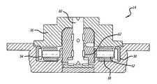
- FIG. 3shows an embodiment of a spindle motor 14 .
- the spindle motor 14includes a rotor 50 and a stator 52 .
- the rotor 50includes permanent magnets 54 that are attached to a shaft hub 56 .
- the stator 52includes a coil 58 . An electromagnetic force is generated to rotate the hub 56 when an AC current is provided to the coil 58 as is known in the art.
- the hub 56is attached to a rotor shaft 60 that also rotates.
- the spindle-motor 14includes a journal bearing 62 that minimizes friction while the shaft 60 is rotating.
- the journal bearing 62typically contains a fluid such as an oil.
- FIG. 4shows an electrical circuit 70 for reading and writing data onto the disks 12 .
- the circuit 70may include a pre-amplifier circuit 72 that is coupled to the heads 20 .
- the pre-amplifier circuit 72has a read data channel 74 and a write data channel 76 that are connected to a read/write channel circuit 78 .
- the pre-amplifier 72also has a read/write enable gate 80 connected to a controller 82 . Data can be written onto the disks 12 , or read from the disks 12 by enabling the read/write enable gate 80 .
- the read/write channel circuit 78is connected to the controller 82 through read and write channels 84 and 86 , respectively, and read and write gates 88 and 90 , respectively.
- the read gate 88is enabled when data is to be read from the disks 12 .
- the write gate 90is to be enabled when writing data to the disks 12 .
- the controller 82may be a digital signal processor that operates in accordance with a software routine, including a routine(s) to write and read data from the disks 12 .
- the read/write channel circuit 78 and controller 82may also be connected to a motor control circuit 92 which controls the voice coil motor 36 and spindle motor 14 of the disk drive 10 .
- the motor control circuit 92provides a current to the voice coil motor 36 and a current to the spindle motor 14 to actuate each component, respectively.
- the controller 82may be connected to a non-volatile memory device 94 .
- the device 94may be a read only memory (“ROM”).
- ROMread only memory
- the non-volatile memory 94may contain the instructions to operate the controller and disk drive.
- the controller 82may have embedded firmware to operate the drive.
- the disk drivemay also include a temperature sensor 96 that is connected to the controller 82 . Although the sensor 96 is shown connected to the controller 82 , it is to be understood that the sensor 96 may be connected to the motor control circuit 92 .
- a further circuit of the integrated circuits 40 of FIG. 1can provide a first current to the spindle motor 14 .
- the threshold temperature valuemay be ⁇ 5° C.
- the currentmay be DC current so that the spindle motor 14 does not rotate.
- the currentmay be AC with a frequency which would not cause rotation of the spindle motor 14 .
- the currentflows through the coil of the spindle motor 14 (see FIG. 3 ).
- the currentgenerates heat that dissipates through the motor 14 .
- the heattransfers into the journal bearing to heat the oil therein.
- the currentis provided for a predetermined time interval to sufficiently heat the oil.
- the time intervalmay vary depending on the temperature and the thermal impedance of the spindle motor.
- the time intervalmay also vary for different levels of current.
- the currentis terminated after the time interval.
- the motor control circuit 92can then provide a second current to the spindle motor 14 to cause motor rotation and a spinning of the disk 12 .
- the second currentis an AC current.
- the scheme disclosedpre-heats the spindle motor 14 to insure that the bearings are at a sufficient operating temperature.
Landscapes
- Engineering & Computer Science (AREA)
- Power Engineering (AREA)
- General Engineering & Computer Science (AREA)
- Manufacturing & Machinery (AREA)
- Mechanical Engineering (AREA)
- Rotational Drive Of Disk (AREA)
Abstract
Description
Claims (19)
Priority Applications (1)
| Application Number | Priority Date | Filing Date | Title |
|---|---|---|---|
| US12/012,883US8582232B2 (en) | 2008-02-05 | 2008-02-05 | Heat assisted spindle motor |
Applications Claiming Priority (1)
| Application Number | Priority Date | Filing Date | Title |
|---|---|---|---|
| US12/012,883US8582232B2 (en) | 2008-02-05 | 2008-02-05 | Heat assisted spindle motor |
Publications (2)
| Publication Number | Publication Date |
|---|---|
| US20090195923A1 US20090195923A1 (en) | 2009-08-06 |
| US8582232B2true US8582232B2 (en) | 2013-11-12 |
Family
ID=40931428
Family Applications (1)
| Application Number | Title | Priority Date | Filing Date |
|---|---|---|---|
| US12/012,883Expired - Fee RelatedUS8582232B2 (en) | 2008-02-05 | 2008-02-05 | Heat assisted spindle motor |
Country Status (1)
| Country | Link |
|---|---|
| US (1) | US8582232B2 (en) |
Families Citing this family (4)
| Publication number | Priority date | Publication date | Assignee | Title |
|---|---|---|---|---|
| US9658629B2 (en) | 2012-03-22 | 2017-05-23 | Seagate Technology Llc | Method and apparatus for controlling the temperature of components |
| US9621088B2 (en)* | 2014-02-27 | 2017-04-11 | General Electric Company | System and method for reducing ice and/or condensation formed on a power component |
| US11382178B2 (en)* | 2019-06-27 | 2022-07-05 | General Electric Company | System and method for heating an electrical bus in an electrical cabinet for cold startup and condensation/frost control |
| DE102022130538A1 (en)* | 2022-11-18 | 2024-05-23 | Zf Cv Systems Global Gmbh | Method for preheating a bearing comprising a temperature-dependent lubricant, computer program and/or computer-readable medium, control device, electric drive, turbomachine, vehicle, in particular commercial vehicle |
Citations (2)
| Publication number | Priority date | Publication date | Assignee | Title |
|---|---|---|---|---|
| JPH11213624A (en)* | 1998-01-28 | 1999-08-06 | Hitachi Ltd | Magnetic disk drive |
| JP2001132752A (en)* | 1999-11-08 | 2001-05-18 | Seiko Instruments Inc | Electric motor |
- 2008
- 2008-02-05USUS12/012,883patent/US8582232B2/ennot_activeExpired - Fee Related
Patent Citations (2)
| Publication number | Priority date | Publication date | Assignee | Title |
|---|---|---|---|---|
| JPH11213624A (en)* | 1998-01-28 | 1999-08-06 | Hitachi Ltd | Magnetic disk drive |
| JP2001132752A (en)* | 1999-11-08 | 2001-05-18 | Seiko Instruments Inc | Electric motor |
Also Published As
| Publication number | Publication date |
|---|---|
| US20090195923A1 (en) | 2009-08-06 |
Similar Documents
| Publication | Publication Date | Title |
|---|---|---|
| US7199974B1 (en) | Read/write head with reduced pole tip protrusion | |
| US9355668B2 (en) | Hard disk drive with contact detection using a spin torque oscillator | |
| US20090128944A1 (en) | Hard disk drive tunneling magnetoresistive annealing heads with a fly on demand heater | |
| US10395678B1 (en) | Method and system for determining slider-disk contact in a magnetic recording disk drive with dual fly-height actuators | |
| KR20030043681A (en) | Hard disk drive comprising heating means and method controlling temperature of internal cavity of hard disk drive | |
| US6867940B2 (en) | Method and apparatus for mitigating thermal pole tip protrusion | |
| US20070206326A1 (en) | Air bearing surface of a hard disk drive head | |
| US8582232B2 (en) | Heat assisted spindle motor | |
| CN114730576B (en) | Thermally assisted magnetic recording (HAMR) disk drive with interface voltage control circuit | |
| US20060187583A1 (en) | Apparatus for controlling slider fly height | |
| US7301719B1 (en) | Clearance sweep test | |
| US20090013203A1 (en) | Method and apparatus for power saving mode in hard disk drive | |
| US10650850B1 (en) | Hard disk drive with write gap conductive structure and dual independent interface voltage control circuitry | |
| JP2007250102A (en) | Storage device | |
| US8040628B2 (en) | Synchronous writing with timing error detection in bit patterned media disk drives | |
| US9245546B1 (en) | Contamination mitigation cap for a hard disk drive actuator pivot assembly | |
| US20120154953A1 (en) | Head with altitude resistant air-bearing surface | |
| US7804660B2 (en) | Method for unloading head without calibration in hard disk drives | |
| US8179640B2 (en) | Head actuator velocity control for electrical power off in a disk drive | |
| US7382565B2 (en) | Method to avoid contact between the head and disk protrusions | |
| US7149058B2 (en) | Actuator latch with variable retention force | |
| US8526140B2 (en) | Reverse flow preventer unit | |
| US10056117B1 (en) | Data storage device baseplate diverter and downstream spoiler | |
| US20100149682A1 (en) | Dynamic pitch and roll sensing in hard disk drives | |
| US20090147390A1 (en) | Detecting head/disk contact using timing jitter |
Legal Events
| Date | Code | Title | Description |
|---|---|---|---|
| AS | Assignment | Owner name:SAMSUNG ELECTRONICS CO., LTD., KOREA, REPUBLIC OF Free format text:ASSIGNMENT OF ASSIGNORS INTEREST;ASSIGNORS:STROM, BRIAN D.;LEE, SUNGCHANG;FERBER, JOERG;REEL/FRAME:020531/0175;SIGNING DATES FROM 20071105 TO 20080202 Owner name:SAMSUNG ELECTRONICS CO., LTD., KOREA, REPUBLIC OF Free format text:ASSIGNMENT OF ASSIGNORS INTEREST;ASSIGNORS:STROM, BRIAN D.;LEE, SUNGCHANG;FERBER, JOERG;SIGNING DATES FROM 20071105 TO 20080202;REEL/FRAME:020531/0175 | |
| AS | Assignment | Owner name:SEAGATE TECHNOLOGY INTERNATIONAL, CAYMAN ISLANDS Free format text:ASSIGNMENT OF ASSIGNORS INTEREST;ASSIGNOR:SAMSUNG ELECTRONICS CO., LTD.;REEL/FRAME:028085/0220 Effective date:20111219 | |
| AS | Assignment | Owner name:SEAGATE TECHNOLOGY LLC, CALIFORNIA Free format text:ASSIGNMENT OF ASSIGNORS INTEREST;ASSIGNOR:SEAGATE TECHNOLOGY INTERNATIONAL;REEL/FRAME:031107/0001 Effective date:20120503 | |
| STCF | Information on status: patent grant | Free format text:PATENTED CASE | |
| FPAY | Fee payment | Year of fee payment:4 | |
| FEPP | Fee payment procedure | Free format text:MAINTENANCE FEE REMINDER MAILED (ORIGINAL EVENT CODE: REM.); ENTITY STATUS OF PATENT OWNER: LARGE ENTITY | |
| LAPS | Lapse for failure to pay maintenance fees | Free format text:PATENT EXPIRED FOR FAILURE TO PAY MAINTENANCE FEES (ORIGINAL EVENT CODE: EXP.); ENTITY STATUS OF PATENT OWNER: LARGE ENTITY | |
| STCH | Information on status: patent discontinuation | Free format text:PATENT EXPIRED DUE TO NONPAYMENT OF MAINTENANCE FEES UNDER 37 CFR 1.362 | |
| FP | Lapsed due to failure to pay maintenance fee | Effective date:20211112 |