US8581139B2 - Electrode and electrode holder with threaded connection - Google Patents
Electrode and electrode holder with threaded connectionDownload PDFInfo
- Publication number
- US8581139B2 US8581139B2US12/960,797US96079710AUS8581139B2US 8581139 B2US8581139 B2US 8581139B2US 96079710 AUS96079710 AUS 96079710AUS 8581139 B2US8581139 B2US 8581139B2
- Authority
- US
- United States
- Prior art keywords
- electrode
- threaded portion
- crest
- female threaded
- electrode holder
- Prior art date
- Legal status (The legal status is an assumption and is not a legal conclusion. Google has not performed a legal analysis and makes no representation as to the accuracy of the status listed.)
- Active, expires
Links
Images


Classifications
- H—ELECTRICITY
- H05—ELECTRIC TECHNIQUES NOT OTHERWISE PROVIDED FOR
- H05H—PLASMA TECHNIQUE; PRODUCTION OF ACCELERATED ELECTRICALLY-CHARGED PARTICLES OR OF NEUTRONS; PRODUCTION OR ACCELERATION OF NEUTRAL MOLECULAR OR ATOMIC BEAMS
- H05H1/00—Generating plasma; Handling plasma
- H05H1/24—Generating plasma
- H05H1/26—Plasma torches
- H05H1/32—Plasma torches using an arc
- H05H1/34—Details, e.g. electrodes, nozzles
- H05H1/3478—Geometrical details
- Y—GENERAL TAGGING OF NEW TECHNOLOGICAL DEVELOPMENTS; GENERAL TAGGING OF CROSS-SECTIONAL TECHNOLOGIES SPANNING OVER SEVERAL SECTIONS OF THE IPC; TECHNICAL SUBJECTS COVERED BY FORMER USPC CROSS-REFERENCE ART COLLECTIONS [XRACs] AND DIGESTS
- Y10—TECHNICAL SUBJECTS COVERED BY FORMER USPC
- Y10T—TECHNICAL SUBJECTS COVERED BY FORMER US CLASSIFICATION
- Y10T29/00—Metal working
- Y10T29/49—Method of mechanical manufacture
- Y10T29/49002—Electrical device making
- Y10T29/49117—Conductor or circuit manufacturing
- Y—GENERAL TAGGING OF NEW TECHNOLOGICAL DEVELOPMENTS; GENERAL TAGGING OF CROSS-SECTIONAL TECHNOLOGIES SPANNING OVER SEVERAL SECTIONS OF THE IPC; TECHNICAL SUBJECTS COVERED BY FORMER USPC CROSS-REFERENCE ART COLLECTIONS [XRACs] AND DIGESTS
- Y10—TECHNICAL SUBJECTS COVERED BY FORMER USPC
- Y10T—TECHNICAL SUBJECTS COVERED BY FORMER US CLASSIFICATION
- Y10T403/00—Joints and connections
- Y10T403/55—Member ends joined by inserted section
- Y10T403/556—Section threaded to member
Definitions
- the present inventionrelates to plasma arc torches and, in particular, to plasma arc torches wherein an electrode and an electrode holder are held to each other or to the torch by way of a threaded connection.
- Plasma arc torchesare commonly used for the working of metal including cutting, welding, surface treatment, melting and annealing. Such torches include an electrode that supports an arc that extends from the electrode to a workpiece in a transferred-arc mode of operation. It is also conventional to surround the arc with a swirling vortex flow of gas, and in some torch designs it is conventional to also envelop the gas and arc in a swirling jet of water.
- the electrode used in conventional torches of the described typetypically comprises an elongate tubular member composed of a material of high thermal conductivity, such as copper or copper alloy.
- the forward or discharge end of the tubular electrodeincludes a bottom end wall having an emissive element embedded therein that supports the arc.
- the opposite end of the electrodeholds the electrode in the torch by way of a threaded connection to an electrode holder.
- the electrode holderis typically an elongate structure held to the torch body by a threaded connection at an end opposite the end at which the electrode is held.
- the electrode holder and the electrodedefine a threaded connection for holding the electrode to the electrode holder.
- the emissive element of the electrodeis composed of a material that has a relatively low work function, which is defined in the art as the potential step, measured in electron volts (eV), which promotes thermionic emission from the surface of a metal at a given temperature. In view of this low work function, the element is thus capable of readily emitting electrons when an electrical potential is applied thereto.
- emissive materialsinclude hafnium, zirconium, tungsten, and alloys thereof.
- a nozzlesurrounds the discharge end of the electrode and provides a pathway for directing the arc towards the workpiece.
- the electrode and the nozzleare maintained at different electrical potential relative to each other.
- the volume defining the gapis most typically filled with flowing air or some other gas used in the torch operation.
- the heat generated by the plasma arcis great.
- the torch component that is subjected to the most intense heatingis the electrode.
- a passageway or boreis formed through the electrode holder and the electrode, and a coolant such as water is circulated through the passageway to cool the electrode.
- the electrodehas a limited life span and is considered a consumable part.
- a torch operatormust periodically replace a consumed electrode by first removing the nozzle and then unthreading the electrode from the electrode holder. A new electrode is then screwed onto the electrode holder and the nozzle is reinstalled so that the plasma arc torch can resume operation.
- the threaded connection between the electrode holder and the electrodemust take into account various constraints.
- Third, a considerable currentis passed through the electrode holder to the electrode, in some cases up to 1,000 amperes of cutting current. Thus, the threaded connection should provide sufficient contact surface area between the electrode and the electrode holder to allow this current to pass through.
- the cost of manufacturing the electrodeshould be as small as possible, especially because the electrode is a consumable part. Similar considerations exist with respect to the threaded connection holding the electrode holder to the torch body.
- the threaded connection in present designssometimes comprises an enlarged female-threaded portion at the end of the electrode holder that is radially larger than the adjacent male-threaded end of the electrode.
- the gap between the electrode holder and the nozzlewould decrease.
- the electrode and electrode holderare at one electrical potential and the nozzle is at a different electrical potential.
- the decrease in the gapmight cause undesired arcing within the torch from the nozzle to the electrode holder.
- a fine threadallows a shorter thread height (i.e. the dimension of the thread in the radial direction) than a corresponding coarser thread as used in conventional torches. This reduced thread height allows more of a gap between the threaded connection and the nozzle.
- fine threadsare more difficult to machine and thus can be more expensive.
- fine threadsare more delicate, are quicker to become unusably worn on the electrode holder when electrodes are repeatedly replaced, and are more likely to be improperly cross-threaded when an operator is installing a new electrode.
- the present inventionwhich includes an electrode holder and an electrode that is removably held to the electrode holder by a novel threaded connection.
- the novel threaded connectionhas relatively low height and, in another aspect of the invention, the engaged portion of a male thread of the electrode and a female thread of the electrode holder can be positioned at least partially within a nozzle chamber of the plasma arc torch.
- the width of the root portion of the electrode threadis wider than the width of the root portion of the electrode holder thread by at least 35%.
- the less-consumable of the two parts, the electrode holderis provided with a more robust crest for its thread that is less likely to be worn and damaged relative to the crest of the thread of the more-consumable electrode.
- the crest profile of the electrode thread and the root profile of the electrode holder threadare consistent with those of a Stub Acme thread.
- the electrodehas a male threaded portion for removably holding the electrode in the plasma arc torch and defines at least one thread form extending helically and at least partially around a thread axis.
- This threaded portiondefines a major diameter comprising a larger diameter of the threaded portion and a minor diameter comprising a smaller diameter of the threaded portion.
- At least two flanksdefine at least one crest profile of the thread form, and each flank extends between the major diameter and the minor diameter.
- Each of the flanks of the crest profiledefines at least one line when viewed in cross section that intersects at a crest apex with the line defined by the other of the flanks of the crest profile.
- the lines of adjacent flanks of adjacent crest profilesintersect at a root apex.
- a nominal pitch diametercan be defined as lying halfway between the diameter of the crest apex and the diameter of the root apex.
- the crests of the male threadare narrower than the roots of the male thread.
- the nominal pitch diameter of the electrodeis not greater than the minor diameter of the electrode.
- the nominal pitch diameter of the electrodeis smaller than the minor diameter of the female thread of the electrode holder.
- the nominal pitch diameter as defined hereinwould be closer to or at the midpoint between the minor and major diameters of the respective components.
- the electrode holdercan be held to the plasma arc torch body by a male thread at the opposite end from the electrode, which male thread corresponds at least in shape to the male thread of the electrode and provides similar advantages inasmuch as the electrode holder can also be consumable, at least relative to the plasma arc torch body.
- eachdefines a mean diameter between the major diameter and the minor diameter.
- a crest portionextends in one direction from the mean diameter
- a root areaextends in an opposite direction from the mean diameter and defines a width along the mean diameter.
- the width of the root area of the thread of the electrodeis wider than the width of the root area of the thread of the electrode holder, and in particular is at least about 35% wider.
- the root area of the electrodemay be at least about 45% wider than the root area of the electrode holder, and further can be at least about 55% wider than the root area of the electrode holder.
- the width of the root areais greater than the width of the crest portion by at least 15%, and can be at least about 55% greater than the width of the crest portion, and may be 95% wider or more.
- a method of manufacturing the body of an electrode for a plasma arc torchcomprises the steps of:
- the present inventionsolves the problems recognized above in that the novel threaded connection provides for the more-consumable electrode to be formed with less material relative to the electrode holder. Some electrodes can be made much shorter as compared to conventional electrodes for corresponding torches. In addition, any threading damage or wear as between the electrode and electrode holder is less likely to be suffered by the less consumable of the two parts, the electrode holder.
- the present inventionalso provides for an electrode and electrode holder threaded engagement to be positioned at least partially within the nozzle chamber of the torch with the male thread on the electrode.
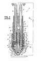
- FIG. 1is a sectioned side view of a conventional shielding gas plasma arc torch illustrating an electrode assembly as used in the prior art
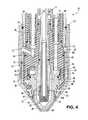
- FIG. 2is a sectioned side view of the torch taken along a different section from FIG. 1 to illustrate coolant flow therethrough;
- FIG. 3is an enlarged view of the lower portion of the torch as seen in FIG. 1 and illustrating the conventional electrode assembly;
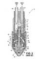
- FIG. 4is an enlarged view of the lower portion of torch as seen in FIG. 1 but showing the advantageous electrode and electrode holder according to the present invention
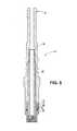
- FIG. 5is a sectional view of the electrode and electrode holder according the invention.
- FIG. 6is a greatly enlarged view of the threaded connection between the electrode holder and the electrode according to the invention.
- FIG. 7is a sectional view of the electrode
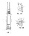
- FIG. 8Ais a greatly enlarged view of the male thread of the electrode
- FIG. 8Bis the same view as FIG. 8A but provides some other dimensional references
- FIG. 9is a sectional view of the electrode holder
- FIG. 10Ais a greatly enlarged view of the female thread of the electrode holder.
- FIG. 10Bis the same view as FIG. 10A but provides other dimensional references corresponding to those in FIG. 8B .
- FIGS. 1-3a prior plasma arc torch that benefits from the invention is broadly indicated by reference numeral 10 .
- a plasma arc torch 10 using an electrode and electrode holder according to the present inventionis illustrated in FIG. 4 .
- the torch 10is a shielding gas torch, which provides a swirling curtain or jet of shielding gas surrounding the electric arc during a working mode of operation of the torch.
- the torch 10includes a generally cylindrical upper or rear insulator body 12 which may be formed of a potting compound or the like, a generally cylindrical main torch body 14 connected to the rear insulator body 12 and generally made of a conductive material such as metal, a generally cylindrical lower or front insulator body 16 connected to the main torch body 14 , an electrode holder assembly 18 extending through the main torch body 14 and front insulator body 16 and supporting an electrode 20 at a free end of the electrode holder assembly, and a nozzle assembly 22 connected to the insulator body 16 adjacent the electrode 20 .
- a plasma gas connector tube 24extends through the rear insulator body 12 and is connected by screw threads (not shown) into a plasma gas passage 26 of the main torch body 14 .
- the plasma gas passage 26extends through the main torch body 14 to a lower end face 28 thereof for supplying a plasma gas (sometimes referred to as a cutting gas), such as oxygen, air, nitrogen, or argon, to a corresponding passage in the insulator body 16 .
- a plasma gassometimes referred to as a cutting gas
- a shielding gas connector tube 30extends through the rear insulator body 12 and is connected by screw threads into a shielding gas passage 32 of the main torch body 14 .
- the shielding gas passage 32extends through the main torch body 14 to the lower end face 28 for supplying a shielding gas, such as argon or air, to a corresponding passage in the insulator body 16 .
- the insulator body 16has an upper end face 34 that abuts the lower end face 28 of the main torch body.
- a plasma gas passage 36extends through the insulator body 16 from the upper end face 34 into a cylindrical counterbore 38 in the lower end of the insulator body 16 .
- the counterbore 38together with the upper end of the nozzle assembly 22 , forms a plasma gas chamber 40 from which plasma gas is supplied to a primary or plasma gas nozzle of the torch.
- plasma gas from a suitable sourceenters the plasma gas chamber 40 by flowing through the plasma gas connector tube 24 , through the plasma gas passage 26 in the main torch body 14 , into the plasma gas passage 36 of the insulator body 16 , which is aligned with the passage 26 , and into the chamber 40 .
- the nozzlewhich is illustrated as a two-part nozzle assembly 22 , includes an upper nozzle member 42 , which has a generally cylindrical upper portion slidingly received within a metal insert sleeve 44 that is inserted into the counterbore 38 of the insulator body 16 .
- An O-ring 46seals the sliding interconnection between the upper nozzle member 42 and the metal insert sleeve 44 .
- a lower nozzle tip 48 of generally frustoconical formalso forms a part of the nozzle assembly 22 , and is threaded into the upper nozzle member 42 .
- the lower nozzle tip 48includes a nozzle exit orifice 50 at the tip end thereof.
- the lower nozzle tip 48 and upper nozzle member 42could alternatively be formed as one unitary nozzle.
- the nozzlechannels the plasma gas from a larger distal opening 49 to the exit orifice 50 .
- a plasma gas flow paththus exists from the plasma gas chamber 40 through the nozzle chamber 41 for directing a jet of plasma gas out the nozzle exit orifice 50 to aid in performing a work operation on a workpiece.
- the plasma gas jetpreferably has a swirl component created, in a known manner; by a hollow cylindrical ceramic gas baffle 52 partially disposed in a counterbore recess 54 of the insulator body 16 .
- a lower end of the baffle 52abuts an annular flange face of the upper nozzle member 42 .
- the baffle 52has non-radial holes (not shown) for directing plasma gas from the plasma gas chamber 40 into a lower portion of the nozzle chamber 41 with a swirl component of velocity.
- the electrode holder assembly 18includes a tubular electrode holder 56 which has its upper end connected by threads 11 within a blind axial bore 58 in the main torch body 14 .
- the electrode holder 56is somewhat consumable, although usually less so than the electrode itself, and thus the electrode holder and the axial bore 58 can also be provided with a threaded connection according to the present invention as discussed below.
- the upper end of electrode holder 56extends through an axial bore 60 formed through the insulator body 16
- the lower end of the electrode holder 56includes an enlarged internally screw-threaded coupler 62 which has an outer diameter slightly smaller than the inner diameter of the ceramic gas baffle 52 which is sleeved over the outside of the coupler 62 .
- the electrode holder 56also includes internal screw threads spaced above the coupler 62 for threadingly receiving a coolant tube 64 which supplies coolant to the electrode 20 , as further described below, and which extends outward from the axial bore of the insulator body 16 into the central passage of the electrode 20 .
- a coolant tube 64which supplies coolant to the electrode 20 , as further described below, and which extends outward from the axial bore of the insulator body 16 into the central passage of the electrode 20 .
- the screw thread connection between those itemsmay be cemented or otherwise secured together during manufacture to form an inseparable electrode holder assembly 18 .
- the electrode 20may be of the type described in U.S. Pat. No. 5,097,111, assigned to the assignee of the present application, and incorporated herein by reference.
- the prior art electrode 20comprises a cup-shaped body whose open upper end is threaded by screw threads 63 into the coupler 62 at the lower end of the electrode holder 56 , and whose capped lower end is closely adjacent the lower end of the coolant tube 64 .
- a coolant circulating spaceexists between the inner surface of the wall of the electrode 20 and the outer surface of the wall of the coolant tube 64 , and between the outer surface of the wall of the coolant tube 64 and the inner surface of the wall of the electrode holder 56 .
- the electrode holder 56includes a plurality of holes 66 for supplying coolant from the space within the electrode holder to a space 68 between the electrode holder and the inner wall of the axial bore 60 in the insulator body 16 .
- a seal 69 located between the holes 66 and the coupler 62seals against the inner wall of the bore 60 to prevent coolant in the space 68 from flowing past the seal 69 toward the coupler 62 .
- a raised annular rib or dam 71 on the outer surface of the electrode holder 56is located on the other side of the holes 66 from the seal 69 , for reasons which will be made apparent below.
- a coolant supply passage 70( FIG. 2 ) extends through the insulator body from the space 68 through the outer cylindrical surface of the insulator body 16 for supplying coolant to the nozzle assembly 22 , as further described below.
- a difference in electrical voltage potentialis established between the electrode 20 and the nozzle tip 48 so that an electric arc forms across the gap therebetween.
- Plasma gasis then flowed through the nozzle assembly 22 and the electric arc is blown outward from the nozzle exit orifice 50 until it attaches to a workpiece, at which point the nozzle assembly 22 is disconnected from the electric source so that the arc exists between the electrode 20 and the workpiece.
- the torchis then in a working mode of operation.
- the insulator body 16includes a shielding gas passage 72 that extends from the upper end face 34 axially into the insulator body, and then angles outwardly and extends through the cylindrical outer surface of the insulator body.
- a nozzle retaining cup assembly 74surrounds the insulator body 16 to create a generally annular shielding gas chamber 76 between the insulator body 16 and the nozzle retaining cup assembly 74 . Shielding gas is supplied through the shielding gas passage 72 of the insulator body 16 into the shielding gas chamber 76 .
- the nozzle retaining cup assembly 74includes a nozzle retaining cup holder 78 and a nozzle retaining cup 80 which is secured within the holder 78 by a snap ring 81 or the like.
- the nozzle retaining cup holder 78is a generally cylindrical sleeve, preferably formed of metal, which is threaded over the lower end of a torch outer housing 82 which surrounds the main torch body 14 . Insulation 84 is interposed between the outer housing 82 and the main torch body 14 .
- the nozzle retaining cup 80preferably is formed of plastic and has a generally cylindrical upper portion that is secured within the cup holder 78 by the snap ring 81 and a generally frustoconical lower portion which extends toward the end of the torch and includes an inwardly directed flange 86 .
- the flange 86confronts an outwardly directed flange 88 on the upper nozzle member 42 and contacts an O-ring 90 disposed therebetween.
- the nozzle assembly 22is thereby made to contact an electrical contact ring secured within the counterbore 38 of the insulator body 16 . More details of the electrical connections within the torch can be found in commonly-owned U.S. Pat. No. 6,215,090, which is incorporated by reference herein in its entirety.
- the nozzle retaining cup 80fits loosely within the cup holder 78 , and includes longitudinal grooves 92 in its outer surface for the passage of shielding gas from the chamber 76 toward the end of the torch. Alternatively or additionally, grooves (not shown) may be formed in the inner surface of the cup holder 78 .
- a shielding gas nozzle 94 of generally frustoconical formconcentrically surrounds and is spaced outwardly of the lower nozzle tip 48 and is held by a shield retainer 96 that is threaded over the lower end of the cup holder 78 .
- a shielding gas flow path 98thus extends from the longitudinal grooves 92 in retaining cup 80 , between the shield retainer 96 and the retaining cup 80 and upper nozzle member 42 , and between the shielding gas nozzle 94 and the lower nozzle tip 48 .
- the shielding gas nozzle 94includes a diffuser 100 that in known manner imparts a swirl to the shielding gas flowing into the flow path between the shielding gas nozzle 94 and the lower nozzle tip 48 .
- a swirling curtain of shielding gasis created surrounding the jet of plasma gas and the arc emanating from the nozzle exit orifice 50 .
- the torch 10includes a coolant inlet connector tube 112 that extends through the rear insulator body 12 and is secured within a coolant inlet passage 114 in the main torch body 14 .
- the coolant inlet passage 114connects to the center axial bore 58 in the main torch body. Coolant is thus supplied into the bore 58 and thence into the internal passage through the electrode holder 56 , through the internal passage of the coolant tube 64 , and into the space between the tube 64 and the electrode 20 .
- Heatis transferred to the liquid coolant (typically water or antifreeze) from the lower end of the electrode (from which the arc emanates) and the liquid then flows through a passage between the lower end of the coolant tube 64 and the electrode 20 and upwardly through the annular space between the coolant tube 64 and the electrode 20 , and then into the annular space between the coolant tube 64 and the electrode holder 18 .
- liquid coolanttypically water or antifreeze
- the coolantthen flows out through the holes 66 into the space 68 and into the passage 70 through the insulator body 16 .
- the seal 69prevents the coolant in the space 68 from flowing toward the coupler 62 at the lower end of the holder 56 , and the dam 71 substantially prevents coolant from flowing past the dam 71 in the other direction, although there is not a positive seal between the dam 71 and the inner wall of the bore 60 .
- the coolant in space 68is largely constrained to flow into the passage 70 .
- the insulator body 16includes a groove or flattened portion 116 that permits coolant to flow from the passage 70 between the insulator body 16 and the nozzle retaining cup 80 and into a coolant chamber 118 which surrounds the upper nozzle member 42 . The coolant flows around the upper nozzle member 42 to cool the nozzle assembly.
- Coolantis returned from the nozzle assembly via a second groove or flattened portion 120 angularly displaced from the portion 116 , and into a coolant return passage 122 in the insulator body 16 .
- the coolant return passage 122extends into a portion of the axial bore 60 that is separated from the coolant supply passage 70 by the dam 71 .
- the coolantthen flows between the electrode holder 56 and the inner wall of the bore 60 and the bore 58 in the main torch body 14 into an annular space 126 which is connected with a coolant return passage 128 formed in the main torch body 14 , and out the coolant return passage 128 via a coolant return connector tube 130 secured therein.
- returned coolantis recirculated in a closed loop back to the torch after being cooled.
- an electrical potential source 210is connected to the main torch body 12 and thus is connected electrically with the electrode 20
- the other side, typically the anode side, of the source 210is connected to the nozzle assembly 22 through a switch 212 and a resistor 214 .
- the anode sideis also connected in parallel to the workpiece 216 with no resistor interposed therebetween.
- a high voltage and high frequencyare imposed across the electrode and nozzle assembly, causing an electric arc to be established across a gap therebetween adjacent the plasma gas nozzle discharge. Plasma gas is flowed through the nozzle assembly to blow the pilot arc outward through the nozzle discharge until the arc attaches to the workpiece.
- the switch 212 connecting the potential source to the nozzle assemblyis then opened, and the torch is in the transferred arc mode for performing a work operation on the workpiece.
- the power supplied to the torchis increased in the transferred arc mode to create a cutting arc, which is of a higher current than the pilot arc.
- the electrode and electrode holder according to the inventioncan also be used with blowback-type torches.
- the electrode holder assembly 18 and novel threaded connection according to the present inventionare illustrated in FIGS. 4-10 .
- the electrode holder assembly 18includes the tubular electrode holder 56 , which has its upper end connected by threads 11 within the blind axial bore in the main torch body, as discussed above.
- the coolant tube 64supplies coolant to the cup-shaped electrode 20 , which has an open distal end secured to the electrode holder 56 by the advantageous threads 15 according to the present invention.
- the threads 15 securing the electrode 20 to the electrode holder 56can be seen in FIG. 5 .
- the electrode holder 56has a female threaded portion 17 formed therein and the electrode 20 has a male threaded portion 19 formed thereon.
- An O-ring 31is provided to ensure adequate sealing and to prevent coolant from escaping from the electrode and electrode holder.
- the electrode 20 and the electrode holder 56can be formed from a variety of different electrically conductive materials, but in one embodiment the electrode holder 56 is made of brass or a brass alloy and the electrode 20 comprises a body made of copper or a copper alloy.
- the coolant tube 64can also be seen in FIG. 5 , and it is illustrated with a distal end have a constant diameter in the axial direction.
- a coolant tube 64 having a distal end with an external diameter larger than a more medial portion of the coolant tubesuch as the coolant tube 64 illustrated in FIGS. 1-3 , could also be used.
- the external diameter of the distal end of the coolant tube 64is less than internal diameter of the passage in the electrode holder through which coolant tube extends, and the threaded portion of the electrode holder is at least partially within the nozzle chamber 41 as seen in FIG. 4 .
- FIG. 6is an enlarged view of the female threaded portion 17 of the electrode holder and the male threaded portion 19 of the electrode threadingly engaged together. The manufacturing clearances between the threads are illustrated.
- the electrode 20is illustrated herein as being removably held in the plasma arc torch by way of an electrode holder 56 , it is within the realm of the invention that the electrode 20 could be held within the torch by being threaded directly to the torch body 14 or some other component.
- the electrode 20 as shown in the enlarged view of FIG. 7comprises a generally cup-shape having the male threaded portion 19 at a proximal end thereof.
- An emissive element 23 and a relatively non-emissive separator 25are held at the opposite end of a body 21 from the male threaded portion 19 .
- the emissive element 23is the component of the electrode from which the arc extends to the workpiece and is formed from an emissive material, such as hafnium.
- the relatively non-emissive separator 25is formed from a relatively non-emissive material such as silver, and serves to prevent the arc from emanating from the body 21 of the electrode 20 instead of the emissive element 23 .
- the male threaded portion 19defines at least one thread form extending helically and at least partially around the axis of the electrode 20 . Although one thread form is illustrated, double-thread forms can also be used in some situations consistent within the scope of the invention.
- the thread formhas a crest portion 27 and a root area 29 and which together define a crest profile for each helix of the thread form.
- the male threaded portion 19defines a minor diameter K and a major diameter D.
- a crest portion 27defines a crest flat 33 and the root area 29 defines a root flat 35 .
- threadscan be formed in accordance with the principles of the present invention that have rounded or partially-rounded roots and crests.
- the male threaded portionalso defines flanks 37 that extend between the crest flats 33 and the root flats 35 .
- the flanks 37are shown as being straight in the drawing, and each defines a line that can be extended as shown by a broken line in the drawings. These extension lines extend towards each other and, at their points of intersection, define a crest apex c a and a root apex r a . It is to be understood that at least one of the apices could comprise an actual apex of a thread profile for some configurations, but in the illustrated embodiments these apices are theoretical.
- a nominal pitch diameter D pis illustrated and is defined as the diameter that lies halfway between the crest apex c a and the root apex r a . Reference here is made to Machinery's Handbook ; Oberg, Jones and Horton; Industrial Press, Inc.; 1979.
- the nominal pitch diameter D plies roughly halfway between the minor diameter K and the major diameter D.
- the nominal pitch diameter D plies much closer to the thread axis.
- the nominal pitch diameter D p of a conventional threadmay pass through the radial middle of the flanks of the thread
- the nominal pitch diameter D pis much smaller and may be no greater than the minor diameter K of the female threaded portion of the electrode holder (shown in FIGS. 10A & 10B ), and in some embodiments may be no greater than the minor diameter K of the electrode.
- the nominal pitch diameter D pmaybe no more than about 105% of the minor diameter K of the electrode.
- the mean diameterallows definition of the invention without relying upon nominal pitch diameters, theoretical apices and extension lines and is helpful in a case, for example, where one or more of the thread forms has a curving profile but still embodies the advantages discussed herein.
- the flanksare illustrated herein as having a flat profile, the flanks could also be curved or segmented, or have some other shape, and still achieve the advantages of the invention.
- the mean diameter for the electrodeis shown in FIG. 8B , where a mean diameter d m is halfway between the minor diameter K and the major diameter D.
- the mean diameter d mpasses through the flanks of the thread and defines both a root area width r w and a crest portion width c w extending along the mean diameter d m .
- the root area width r w of the male threaded portionis larger than the crest portion width c w .
- the electrode 20can have the following dimensions.
- the flanks of the threaded portion relative to the axis of the electrode 20are manufactured so as to provide an included angle 2 ⁇ that is 29°.
- the pitch p of the threadis 0.0833′′, which provides a thread count of 12 threads per inch (tpi).
- the length of the threaded portioncan be 0.193′′ in the axial direction so that only a small amount of turning is necessary to seat the electrode 20 , which can assist in rapid assembly.
- the minor diameter Kis 0.389′′ and the major diameter D is 0.441′′.
- the crest apex c athus lies at a diameter of 0.526′′ and the root apex r a lies at 0.203′′, and the nominal pitch diameter D p halfway between these two diameters is 0.364′′.
- the nominal pitch diameter D pis less than the minor diameter K of the electrode threaded portion.
- the width of the root area r wis 0.055′′ and the width of the crest portion c w is 0.028′′.
- the width of the root area r wis greater than the width of the crest portion c w by at least 15%, and may be 55% wider, or 95% wider or more.
- the profile of the thread crestmay be consistent with a standard Stub Acme thread (as defined in ASME/ANSI standard for Stub Acme threads, No. B1.8, which is incorporated herein by reference) even though the root profile is wider than a standard Stub Acme thread.
- the crest flat 33has a width of 0.022′′
- the root flat 35has a width of 0.048′′, which is greater than 0.4224 times the pitch of threaded portion, and does not meet the ASME/ANSI standard.
- the thread formcan be machined using tooling designed for a Stub Acme thread of 8 tpi even though the thread count for the final thread is 12 tpi due to the enlarged root profile relative to the crest profile of the thread form.
- the advantageous threaded connection according to the present inventioncan be made using conventional tooling.
- Such a methodcan comprise an initial step of forming an electrode blank from a base material, such as copper, and defining at least one cylindrical surface on the exterior of the blank. Thereafter, material is removed from the cylindrical surface so as to define at least one helical thread form in the electrode blank. In particular, material is removed so as to form flanks defining the thread form; the flanks defining at least one line when viewed in cross section that intersects at a crest apex with a line defined by another of the flanks and also intersects at a root apex with a line defined by yet another of the flanks. The removal of material is discontinued at a depth that is above a depth halfway between the root apex and the crest apex. While machining is a practical way of forming the electrode from the blank, especially when using the conventional tooling as noted above, the electrode can also formed using other manufacturing methods, such as casting, etc.
- FIGS. 9 , 10 A and 10 BA corresponding electrode holder 56 is illustrated in FIGS. 9 , 10 A and 10 B.
- the major diameter Dhas a value of 0.449′′ and the minor diameter K has a value of 0.395′′.
- the nominal pitch diameter of the electrode(0.364′′) is not greater the minor diameter of the electrode holder.
- the crest apex c a of the electrode holderthus lies at a diameter of 0.235′′ and the root apex r a lies at 0.557′′, and thus the nominal pitch diameter D p of the electrode holder halfway between these two diameters is 0.396′′, which is larger than the minor diameter of the electrode holder.
- the profile of the thread rootis consistent with a standard Stub Acme thread even though the crest profile is wider than a standard Stub Acme thread.
- the crest flat 33has a width of 0.041′′, which is greater than 0.4224 times the pitch of threaded portion, and does not meet the ASME/ANSI standard for Stub Acme threads, No. B1.8.
- the root flat 35has a width of 0.028′′.
- the crest portion width c wis 0.048′′, and is larger than the root area width r w of 0.035′′.
- the thread formcan be machined using tooling designed for a Stub Acme thread of 14 tpi even though the thread count for the final thread is 12 tpi due to the enlarged crest portion relative to the root area of the thread.
- the electrode holdercan be formed using a similar method to that described above for the electrode.
- the width of the root area r w of the electrodeis 0.055′′ and the width of the root area r w of the electrode holder is 0.035′′ as noted above.
- the width of the root area of the electrodeis greater than the width of the root area of the electrode holder by at least 35%, and may be 45% wider, or 55% wider or more.
- the electrode holder 56also has an opposite male threaded portion 11 as shown in FIG. 5 .
- the dimensionsare similar to those of the male threaded portion of the electrode.
- the width of the root area r wis 0.055′′ and the width of the crest portion c w is 0.028′′.
- the width of the root area r wis greater than the width of the crest portion c w by at least 15%, and may be 55% wider, or 95% wider or more.
- the present inventionadvantageously provides a threaded connection that can be made between the electrode holder 56 and the electrode 20 with relatively low crest/root height compared to conventional designs.
- the narrower crest profilebeing provided on the male thread portion of the electrode and the male thread portion of the electrode holder, the same relative compactness can be achieved by forming the narrower crest profile on a corresponding female threaded portion of the electrode holder and/or a female threaded portion of the torch body.
- the positions of the male and female threads as between the electrode and the electrode holder and/or as between the electrode holder and the torch bodycan be reversed from those illustrated and still provide advantages of the type discussed above.
- the compact threaded connectionprovides an advantageous dimensional relationship within the torch.
- the present inventionalso includes a more distal position for the electrode holder in the torch, and the threaded portion of the electrode holder engaged with the threaded portion of the electrode is advantageously partially or wholly within the nozzle chamber 41 , as can be seen in FIG. 4 .
- the electrode 20is much shorter than prior art electrodes of this type, which reduces manufacturing costs. This is especially important because the electrode is a consumable part and is the most frequently replaced part of a plasma arc torch.
- the electrode holder 56may also need to be periodically replaced. However, the replacement rate is much less often than that of the electrode 20 .
- the “unequal” thread profiles of the electrode 20 and the electrode holder 56allow for detrimental wear of the threads to be allocated more to the consumable electrode 20 than to the electrode holder 56 .
Landscapes
- Physics & Mathematics (AREA)
- Engineering & Computer Science (AREA)
- Plasma & Fusion (AREA)
- Spectroscopy & Molecular Physics (AREA)
- Geometry (AREA)
- Plasma Technology (AREA)
- Arc Welding In General (AREA)
Abstract
Description
- forming an electrode blank from a base material and defining at least one external cylindrical surface;
- removing material from the cylindrical surface so as to define at least one helical thread form in the electrode blank, the removing step comprising the steps of;
- removing material so as to form flanks defining the thread form, the flanks defining at least one line when viewed in cross section that intersects at a crest apex with a line defined by another of the flanks and also intersects at a root apex with a line defined by yet another of the flanks, and
| Conventional | Conventional | |||
| New-Male | New-Male | (½″)-Male | (⅜″)-Male | |
| Electrode/ | Electrode | Electrode/ | Electrode | |
| Female | Holder/ | Female | Holder/ | |
| Electrode | Female | Electrode | Female | |
| Holder | Torch Body | Holder | Torch Body | |
| Threads per | 12 | 12 | 20 | 24 |
| Male Dp | 0.364 | 0.294 | 0.464 | 0.345 |
| Male K | 0.389 | 0.317 | 0.437 | 0.322 |
| Male D | 0.441 | 0.369 | 0.495 | 0.370 |
| Female Dp | 0.396 | 0.324 | 0.470 | 0.350 |
| Female K | 0.395 | 0.323 | 0.452 | 0.335 |
| Female D | 0.449 | 0.377 | 0.506 | 0.381 |
| P | 0.083 | 0.083 | 0.050 | 0.042 |
| 2α (deg.) | 29 | 29 | 60 | 60 |
| Male dm | 0.415 | 0.343 | 0.466 | 0.346 |
| Female dm | 0.422 | 0.350 | 0.479 | 0.358 |
| Female rw | 0.035 | 0.035 | 0.020 | 0.017 |
| Female cw | 0.048 | 0.048 | 0.030 | 0.025 |
| Male rw | 0.055 | 0.055 | 0.026 | 0.022 |
| Male cw | 0.028 | 0.028 | 0.024 | 0.020 |
| Female Crest Flat | 0.041 | 0.041 | 0.014 | 0.012 |
| Female Root Flat | 0.028 | 0.028 | 0.004 | 0.003 |
| Male Crest Flat | 0.022 | 0.022 | 0.007 | 0.006 |
| Male Root Flat | 0.048 | 0.048 | 0.009 | 0.008 |
| All dimensions are inches except as noted | ||||
Claims (12)
Priority Applications (1)
| Application Number | Priority Date | Filing Date | Title |
|---|---|---|---|
| US12/960,797US8581139B2 (en) | 2004-09-03 | 2010-12-06 | Electrode and electrode holder with threaded connection |
Applications Claiming Priority (4)
| Application Number | Priority Date | Filing Date | Title |
|---|---|---|---|
| US10/933,877US7081597B2 (en) | 2004-09-03 | 2004-09-03 | Electrode and electrode holder with threaded connection |
| US11/419,405US7423235B2 (en) | 2004-09-03 | 2006-05-19 | Electrode and electrode holder with threaded connection |
| US12/187,747US20080293320A1 (en) | 2004-09-03 | 2008-08-07 | Electrode and electrode holder with threaded connection |
| US12/960,797US8581139B2 (en) | 2004-09-03 | 2010-12-06 | Electrode and electrode holder with threaded connection |
Related Parent Applications (1)
| Application Number | Title | Priority Date | Filing Date |
|---|---|---|---|
| US12/187,747DivisionUS20080293320A1 (en) | 2004-09-03 | 2008-08-07 | Electrode and electrode holder with threaded connection |
Publications (2)
| Publication Number | Publication Date |
|---|---|
| US20110073574A1 US20110073574A1 (en) | 2011-03-31 |
| US8581139B2true US8581139B2 (en) | 2013-11-12 |
Family
ID=35431646
Family Applications (4)
| Application Number | Title | Priority Date | Filing Date |
|---|---|---|---|
| US10/933,877Expired - LifetimeUS7081597B2 (en) | 2004-09-03 | 2004-09-03 | Electrode and electrode holder with threaded connection |
| US11/419,405Expired - LifetimeUS7423235B2 (en) | 2004-09-03 | 2006-05-19 | Electrode and electrode holder with threaded connection |
| US12/187,747AbandonedUS20080293320A1 (en) | 2004-09-03 | 2008-08-07 | Electrode and electrode holder with threaded connection |
| US12/960,797Active2027-02-26US8581139B2 (en) | 2004-09-03 | 2010-12-06 | Electrode and electrode holder with threaded connection |
Family Applications Before (3)
| Application Number | Title | Priority Date | Filing Date |
|---|---|---|---|
| US10/933,877Expired - LifetimeUS7081597B2 (en) | 2004-09-03 | 2004-09-03 | Electrode and electrode holder with threaded connection |
| US11/419,405Expired - LifetimeUS7423235B2 (en) | 2004-09-03 | 2006-05-19 | Electrode and electrode holder with threaded connection |
| US12/187,747AbandonedUS20080293320A1 (en) | 2004-09-03 | 2008-08-07 | Electrode and electrode holder with threaded connection |
Country Status (4)
| Country | Link |
|---|---|
| US (4) | US7081597B2 (en) |
| EP (1) | EP1633172B1 (en) |
| JP (1) | JP5086533B2 (en) |
| CA (1) | CA2517639C (en) |
Cited By (30)
| Publication number | Priority date | Publication date | Assignee | Title |
|---|---|---|---|---|
| US20160050740A1 (en)* | 2014-08-12 | 2016-02-18 | Hypertherm, Inc. | Cost Effective Cartridge for a Plasma Arc Torch |
| US9313871B2 (en) | 2013-07-31 | 2016-04-12 | Lincoln Global, Inc. | Apparatus and method of aligning and securing components of a liquid cooled plasma arc torch and improved torch design |
| US9338872B2 (en) | 2013-07-31 | 2016-05-10 | Lincoln Global, Inc. | Apparatus and method of aligning and securing components of a liquid cooled plasma arc torch |
| US9386679B2 (en) | 2013-07-31 | 2016-07-05 | Lincoln Global, Inc. | Apparatus and method of aligning and securing components of a liquid cooled plasma arc torch using a multi-thread connection |
| US9398679B2 (en) | 2014-05-19 | 2016-07-19 | Lincoln Global, Inc. | Air cooled plasma torch and components thereof |
| US9457419B2 (en) | 2014-09-25 | 2016-10-04 | Lincoln Global, Inc. | Plasma cutting torch, nozzle and shield cap |
| US9560733B2 (en) | 2014-02-24 | 2017-01-31 | Lincoln Global, Inc. | Nozzle throat for thermal processing and torch equipment |
| US9572242B2 (en) | 2014-05-19 | 2017-02-14 | Lincoln Global, Inc. | Air cooled plasma torch and components thereof |
| US9572243B2 (en) | 2014-05-19 | 2017-02-14 | Lincoln Global, Inc. | Air cooled plasma torch and components thereof |
| US9681528B2 (en) | 2014-08-21 | 2017-06-13 | Lincoln Global, Inc. | Rotatable plasma cutting torch assembly with short connections |
| US9686848B2 (en) | 2014-09-25 | 2017-06-20 | Lincoln Global, Inc. | Plasma cutting torch, nozzle and shield cap |
| US9730307B2 (en) | 2014-08-21 | 2017-08-08 | Lincoln Global, Inc. | Multi-component electrode for a plasma cutting torch and torch including the same |
| US9736917B2 (en) | 2014-08-21 | 2017-08-15 | Lincoln Global, Inc. | Rotatable plasma cutting torch assembly with short connections |
| US9781816B2 (en) | 2014-10-20 | 2017-10-03 | Hypertherm, Inc. | Interchangeable power contact for a plasma arc cutting system |
| US9900972B2 (en) | 2015-08-04 | 2018-02-20 | Hypertherm, Inc. | Plasma arc cutting systems, consumables and operational methods |
| US9949356B2 (en) | 2012-07-11 | 2018-04-17 | Lincoln Global, Inc. | Electrode for a plasma arc cutting torch |
| US9981335B2 (en) | 2013-11-13 | 2018-05-29 | Hypertherm, Inc. | Consumable cartridge for a plasma arc cutting system |
| US10278274B2 (en) | 2015-08-04 | 2019-04-30 | Hypertherm, Inc. | Cartridge for a liquid-cooled plasma arc torch |
| US10413991B2 (en) | 2015-12-29 | 2019-09-17 | Hypertherm, Inc. | Supplying pressurized gas to plasma arc torch consumables and related systems and methods |
| USD861758S1 (en) | 2017-07-10 | 2019-10-01 | Lincoln Global, Inc. | Vented plasma cutting electrode |
| US10456855B2 (en) | 2013-11-13 | 2019-10-29 | Hypertherm, Inc. | Consumable cartridge for a plasma arc cutting system |
| US10589373B2 (en) | 2017-07-10 | 2020-03-17 | Lincoln Global, Inc. | Vented plasma cutting electrode and torch using the same |
| US10863610B2 (en) | 2015-08-28 | 2020-12-08 | Lincoln Global, Inc. | Plasma torch and components thereof |
| US11278983B2 (en) | 2013-11-13 | 2022-03-22 | Hypertherm, Inc. | Consumable cartridge for a plasma arc cutting system |
| US11310901B2 (en) | 2015-08-28 | 2022-04-19 | Lincoln Global, Inc. | Plasma torch and components thereof |
| US11432393B2 (en) | 2013-11-13 | 2022-08-30 | Hypertherm, Inc. | Cost effective cartridge for a plasma arc torch |
| US11684995B2 (en) | 2013-11-13 | 2023-06-27 | Hypertherm, Inc. | Cost effective cartridge for a plasma arc torch |
| US12217118B2 (en) | 2012-04-04 | 2025-02-04 | Hypertherm, Inc. | Configuring signal devices in thermal processing systems |
| US12275082B2 (en) | 2013-11-13 | 2025-04-15 | Hypertherm, Inc. | Consumable cartridge for a plasma arc cutting system |
| US12280441B2 (en) | 2017-02-09 | 2025-04-22 | Hypertherm, Inc. | Swirl ring and contact element for a plasma arc torch cartridge |
Families Citing this family (33)
| Publication number | Priority date | Publication date | Assignee | Title |
|---|---|---|---|---|
| US8721849B2 (en)* | 2005-03-02 | 2014-05-13 | Miura Co., Ltd. | Electrode holder |
| US9560732B2 (en) | 2006-09-13 | 2017-01-31 | Hypertherm, Inc. | High access consumables for a plasma arc cutting system |
| US10194516B2 (en) | 2006-09-13 | 2019-01-29 | Hypertherm, Inc. | High access consumables for a plasma arc cutting system |
| US9662747B2 (en) | 2006-09-13 | 2017-05-30 | Hypertherm, Inc. | Composite consumables for a plasma arc torch |
| US10098217B2 (en)* | 2012-07-19 | 2018-10-09 | Hypertherm, Inc. | Composite consumables for a plasma arc torch |
| JP2008294191A (en)* | 2007-05-24 | 2008-12-04 | Disco Abrasive Syst Ltd | Wafer division method |
| KR100967016B1 (en)* | 2007-09-20 | 2010-06-30 | 주식회사 포스코 | Plasma torch device and plasma processing method |
| JP5444860B2 (en)* | 2008-06-24 | 2014-03-19 | 三菱マテリアル株式会社 | Polycrystalline silicon production equipment |
| DE102008062731C5 (en)* | 2008-12-18 | 2012-06-14 | Kjellberg Finsterwalde Plasma Und Maschinen Gmbh | Electrode for a plasma torch |
| DE102009016932B4 (en)* | 2009-04-08 | 2013-06-20 | Kjellberg Finsterwalde Plasma Und Maschinen Gmbh | Cooling tubes and electrode holder for an arc plasma torch and arrangements of the same and arc plasma torch with the same |
| US8304693B2 (en)* | 2009-07-13 | 2012-11-06 | Illinois Tool Works Inc. | Refractory materials reinforced composites for the GMAW contact tips |
| US8258423B2 (en)* | 2009-08-10 | 2012-09-04 | The Esab Group, Inc. | Retract start plasma torch with reversible coolant flow |
| DE102009059108A1 (en)* | 2009-12-18 | 2011-06-22 | Holma Ag | Electrode with cooling tube for a plasma cutting device |
| US8395070B2 (en) | 2010-04-01 | 2013-03-12 | American Torch Tip | Electrical contact point device for use in a plasma arc cutting torch |
| US8633417B2 (en)* | 2010-12-01 | 2014-01-21 | The Esab Group, Inc. | Electrode for plasma torch with novel assembly method and enhanced heat transfer |
| ES2523579T3 (en)* | 2010-12-17 | 2014-11-27 | Stryker Trauma Gmbh | Bone fixation and manufacturing procedure |
| US8901451B2 (en) | 2011-08-19 | 2014-12-02 | Illinois Tool Works Inc. | Plasma torch and moveable electrode |
| EP2642831A1 (en) | 2012-03-22 | 2013-09-25 | Hollberg, Manfred | Plasma electrode for a plasma arc torch and method for its manufacture |
| EP2642832A1 (en) | 2012-03-23 | 2013-09-25 | Manfred Hollberg | Plasma electrode for a plasma arc torch with exchangeable electrode tip |
| EP3024783A1 (en) | 2013-07-26 | 2016-06-01 | SABIC Global Technologies B.V. | Method and apparatus for producing high purity phosgene |
| WO2015013644A1 (en) | 2013-07-26 | 2015-01-29 | Sabic Innovative Plastics Ip B.V. | Method and apparatus for producing high purity phosgene |
| US9609733B2 (en) | 2013-11-12 | 2017-03-28 | The Esab Group, Inc. | Plasma arc torch and method for assembling and disassembling a plasma arc torch |
| JP6316446B2 (en) | 2014-02-04 | 2018-04-25 | サビック グローバル テクノロジーズ ベスローテン フェンノートシャップ | Method for producing carbonate |
| WO2015119982A2 (en) | 2014-02-04 | 2015-08-13 | Sabic Global Technologies B.V. | Method for producing carbonates |
| US9967964B2 (en)* | 2014-05-30 | 2018-05-08 | Hypertherm, Inc. | Cooling plasma cutting system consumables and related systems and methods |
| CN104320901A (en)* | 2014-10-25 | 2015-01-28 | 周开根 | Cathode cooling structure of plasma spraying gun |
| US10208263B2 (en)* | 2015-08-27 | 2019-02-19 | Cogent Energy Systems, Inc. | Modular hybrid plasma gasifier for use in converting combustible material to synthesis gas |
| RU2662445C1 (en)* | 2016-03-28 | 2018-07-26 | Гипертерм, Инк. | Advanced system for plasma arc cutting, dispensable materials and working methods |
| US10639748B2 (en) | 2017-02-24 | 2020-05-05 | Lincoln Global, Inc. | Brazed electrode for plasma cutting torch |
| US11134559B2 (en)* | 2017-07-04 | 2021-09-28 | Norsk Titanium As | Plasma torch system |
| US10926238B2 (en) | 2018-05-03 | 2021-02-23 | Cogent Energy Systems, Inc. | Electrode assembly for use in a plasma gasifier that converts combustible material to synthesis gas |
| JP7106469B2 (en)* | 2019-02-20 | 2022-07-26 | 信越化学工業株式会社 | Polycrystalline silicon manufacturing equipment |
| CZ308592B6 (en)* | 2019-10-21 | 2020-12-16 | Thermacut, K.S. | A part of a cutting or welding torch comprising a thread |
Citations (40)
| Publication number | Priority date | Publication date | Assignee | Title |
|---|---|---|---|---|
| US1828856A (en) | 1928-01-18 | 1931-10-27 | Dardelet Threadlock Corp | Screw-thread coupled member |
| US4152533A (en) | 1978-04-27 | 1979-05-01 | Great Lakes Carbon Corporation | Electrode joint |
| US4375340A (en) | 1980-03-21 | 1983-03-01 | Great Lakes Carbon Corporation | Carbon electrode joint |
| JPS61253140A (en) | 1985-05-02 | 1986-11-11 | Matsushita Electric Ind Co Ltd | Manufacturing method of welding nozzle |
| JPH01183315A (en) | 1988-01-11 | 1989-07-21 | Teledyne Ind Inc | Chaser and chaser device |
| US4954683A (en) | 1989-05-26 | 1990-09-04 | Thermal Dynamics Corporation | Plasma arc gouger |
| JPH0335112A (en) | 1989-06-30 | 1991-02-15 | Okuma Mach Works Ltd | Measurement of pitch and effective diameter of screw and machining method for screw |
| US5023425A (en) | 1990-01-17 | 1991-06-11 | Esab Welding Products, Inc. | Electrode for plasma arc torch and method of fabricating same |
| US5039837A (en) | 1990-02-23 | 1991-08-13 | Tescom Corporation | Plasma torch head, body, handle and control circuitry |
| US5052871A (en) | 1989-06-20 | 1991-10-01 | Mabey Hire Company Limited | Connected screw threads |
| US5097111A (en) | 1990-01-17 | 1992-03-17 | Esab Welding Products, Inc. | Electrode for plasma arc torch and method of fabricating same |
| US5124525A (en) | 1991-08-27 | 1992-06-23 | Esab Welding Products, Inc. | Plasma arc torch having improved nozzle assembly |
| US5160327A (en) | 1991-05-31 | 1992-11-03 | Vance Products Incorporated | Rotational pressure drive for a medical syringe |
| DE4234267A1 (en) | 1991-10-14 | 1993-04-15 | Binzel Alexander Gmbh Co Kg | Plasma burner head for welding or cutting tool - + with different cooling element and corresponding electrode holder configuration for different applications |
| JPH0615875Y2 (en) | 1987-06-22 | 1994-04-27 | 株式会社吉野工業所 | Food container |
| EP0599211A1 (en) | 1992-11-25 | 1994-06-01 | Ucar Carbon Technology Corporation | Self centering electrode joint |
| US5451739A (en) | 1994-08-19 | 1995-09-19 | Esab Group, Inc. | Electrode for plasma arc torch having channels to extend service life |
| US5473140A (en) | 1994-03-14 | 1995-12-05 | Miller Electric Mfg. Co. | Welding nozzle retaining ring |
| US5491321A (en) | 1992-02-26 | 1996-02-13 | Tweco Products, Inc. | Welding gun assembly |
| JPH09141446A (en) | 1995-11-15 | 1997-06-03 | Komatsu Ltd | Cartridge plasma torch |
| US5676864A (en) | 1997-01-02 | 1997-10-14 | American Torch Tip Company | Electrode for plasma arc torch |
| US5681489A (en) | 1995-12-13 | 1997-10-28 | The Esab Group, Inc. | Plasma arc torch including means for disabling power source |
| US5685680A (en) | 1996-05-02 | 1997-11-11 | Nylok Fastener Corporation | Coated threaded fasteners with coating-free crests |
| US5747767A (en) | 1995-09-13 | 1998-05-05 | The Esab Group, Inc. | Extended water-injection nozzle assembly with improved centering |
| US5760373A (en) | 1995-12-27 | 1998-06-02 | Miller Electric Manufacturing Company | Enhanced contact area quick release mig gun tip |
| US5767472A (en) | 1997-01-24 | 1998-06-16 | American Torch Tip Company | Method of repairing a spent electrode for plasma arc torch |
| US6156995A (en) | 1998-12-02 | 2000-12-05 | The Esab Group, Inc. | Water-injection nozzle assembly with insulated front end |
| US6307179B1 (en) | 1999-10-15 | 2001-10-23 | American Torch Tip Company | Wire welding gun having improved connection between a contact tip and its mating part |
| US6346685B2 (en) | 1998-03-06 | 2002-02-12 | The Esab Group, Inc. | Plasma arc torch |
| US6362450B1 (en)* | 2001-01-30 | 2002-03-26 | The Esab Group, Inc. | Gas flow for plasma arc torch |
| JP2002102407A (en) | 1993-06-18 | 2002-04-09 | Paul Costain | Joint protector system, and method to protect connecting member |
| JP2002248576A (en) | 2001-02-26 | 2002-09-03 | Nippon Steel Corp | Cooling structure of plasma torch |
| US6525297B2 (en) | 2001-02-16 | 2003-02-25 | Illinois Tool Works Inc. | Mig gun nozzle with reduced cross-sectional area at the front |
| US6525291B1 (en) | 1999-09-21 | 2003-02-25 | Hypertherm, Inc. | Process and apparatus for cutting or welding a workpiece |
| US6563075B1 (en) | 2001-12-20 | 2003-05-13 | The Esab Group, Inc. | Method of forming an electrode |
| US20030173339A1 (en) | 2000-06-21 | 2003-09-18 | Fryer Paul Chalfont | High temperature tooling |
| US20030209525A1 (en) | 2002-05-09 | 2003-11-13 | American Torch Tip: | Electrodes and nozzles having improved connection and quick release |
| US6686559B1 (en) | 2002-04-02 | 2004-02-03 | The American Torch Tip Company | Electrode for plasma arc torch and method of making the same |
| US6689987B2 (en) | 2001-02-16 | 2004-02-10 | Illinois Tool Works Inc. | Welding contact tip with rolled threads |
| JP2004090013A (en) | 2002-08-30 | 2004-03-25 | Daihen Corp | Nozzle of consumable electrode gas shielded arc welding torch |
Family Cites Families (35)
| Publication number | Priority date | Publication date | Assignee | Title |
|---|---|---|---|---|
| ATE102777T1 (en)* | 1988-05-04 | 1994-03-15 | Acrylicon Norge As | SURFACE COVERING. |
| JP3525426B2 (en)* | 1997-11-28 | 2004-05-10 | トヨタ自動車株式会社 | Radar equipment |
| US6933887B2 (en)* | 1998-09-21 | 2005-08-23 | Ipr Licensing, Inc. | Method and apparatus for adapting antenna array using received predetermined signal |
| JP3447269B2 (en)* | 1999-04-02 | 2003-09-16 | サムスン エレクトロニクス カンパニー リミテッド | Apparatus and method for interleaving / deinterleaving in a communication system |
| AU5567300A (en)* | 1999-06-23 | 2001-01-09 | Japan As Represented By President Of Hokkaido University | Radio device |
| US6795392B1 (en)* | 2000-03-27 | 2004-09-21 | At&T Corp. | Clustered OFDM with channel estimation |
| US7013165B2 (en)* | 2000-08-16 | 2006-03-14 | Samsung Electronics Co., Ltd. | Antenna array apparatus and beamforming method using GPS signal for base station in mobile telecommunication system |
| CN1593031A (en)* | 2000-11-30 | 2005-03-09 | 阿雷伊通讯有限公司 | Training sequences for radio communication systems |
| US6847832B2 (en)* | 2001-03-09 | 2005-01-25 | Kathrein-Werke Kg | System and method for providing phase matching with optimized beam widths |
| KR100511292B1 (en)* | 2002-04-30 | 2005-08-31 | 엘지전자 주식회사 | Update method for beamforming weight vector of rake receiver and receiving apparatus using beamforming weight vector |
| EP1455461A1 (en)* | 2003-03-03 | 2004-09-08 | STMicroelectronics N.V. | Method for processing ultra wide band signals in wireless system, and corresponding device |
| US7039370B2 (en)* | 2003-10-16 | 2006-05-02 | Flarion Technologies, Inc. | Methods and apparatus of providing transmit and/or receive diversity with multiple antennas in wireless communication systems |
| KR100957354B1 (en)* | 2003-11-10 | 2010-05-12 | 삼성전자주식회사 | Apparatus and Method for Forward Beam Formation in Smart Antenna System |
| US7312750B2 (en)* | 2004-03-19 | 2007-12-25 | Comware, Inc. | Adaptive beam-forming system using hierarchical weight banks for antenna array in wireless communication system |
| US7450659B2 (en)* | 2004-03-29 | 2008-11-11 | Agilent Technologies, Inc. | Digital modulator employing a polyphase up-converter structure |
| US8619907B2 (en)* | 2004-06-10 | 2013-12-31 | Agere Systems, LLC | Method and apparatus for preamble training in a multiple antenna communication system |
| TWI241790B (en)* | 2004-07-16 | 2005-10-11 | Ind Tech Res Inst | Hybrid beamforming apparatus and method for the same |
| KR101023366B1 (en)* | 2004-10-27 | 2011-03-18 | 삼성전자주식회사 | Apparatus and method for transmitting / receiving signals in a multiple input multiple output wireless communication system using a beamforming method |
| US8515359B2 (en)* | 2005-03-09 | 2013-08-20 | Intel Corporation | Method and apparatus to provide low cost transmit beamforming for network devices |
| US8830846B2 (en)* | 2005-04-04 | 2014-09-09 | Interdigital Technology Corporation | Method and system for improving responsiveness in exchanging frames in a wireless local area network |
| US7342535B2 (en)* | 2005-04-08 | 2008-03-11 | Samsung Electronics Co., Ltd. | Beam-forming apparatus and method using a spatial interpolation based on regular spatial sampling |
| US7710319B2 (en)* | 2006-02-14 | 2010-05-04 | Sibeam, Inc. | Adaptive beam-steering methods to maximize wireless link budget and reduce delay-spread using multiple transmit and receive antennas |
| US20070189412A1 (en)* | 2006-02-15 | 2007-08-16 | Samsung Electronics Co., Ltd. | Method and system for sounding packet exchange in wireless communication systems |
| US20080101493A1 (en)* | 2006-10-27 | 2008-05-01 | Samsung Electronics Co., Ltd. | Method and system for computing a spatial spreading matrix for space-time coding in wireless communication systems |
| KR100965687B1 (en)* | 2006-11-07 | 2010-06-24 | 삼성전자주식회사 | Beam forming apparatus and method in communication system, and system accordingly |
| US8040856B2 (en)* | 2006-12-04 | 2011-10-18 | Samsung Electronics Co., Ltd. | System and method for wireless communication of uncompressed high definition video data using a beamforming acquisition protocol |
| US8265177B2 (en)* | 2006-12-04 | 2012-09-11 | Samsung Electronics Co., Ltd. | System and method for wireless communication of uncompressed high definition video data using beambook-constructed beamforming signals |
| US7714783B2 (en)* | 2007-08-02 | 2010-05-11 | Samsung Electronics Co., Ltd. | Method and system for analog beamforming in wireless communications |
| US7929918B2 (en)* | 2007-08-13 | 2011-04-19 | Samsung Electronics Co., Ltd. | System and method for training the same type of directional antennas that adapts the training sequence length to the number of antennas |
| US7714781B2 (en)* | 2007-09-05 | 2010-05-11 | Samsung Electronics Co., Ltd. | Method and system for analog beamforming in wireless communication systems |
| US20090121935A1 (en)* | 2007-11-12 | 2009-05-14 | Samsung Electronics Co., Ltd. | System and method of weighted averaging in the estimation of antenna beamforming coefficients |
| US8165595B2 (en)* | 2008-01-25 | 2012-04-24 | Samsung Electronics Co., Ltd. | System and method for multi-stage antenna training of beamforming vectors |
| US8051037B2 (en)* | 2008-01-25 | 2011-11-01 | Samsung Electronics Co., Ltd. | System and method for pseudorandom permutation for interleaving in wireless communications |
| US8280445B2 (en)* | 2008-02-13 | 2012-10-02 | Samsung Electronics Co., Ltd. | System and method for antenna training of beamforming vectors by selective use of beam level training |
| US8478204B2 (en)* | 2008-07-14 | 2013-07-02 | Samsung Electronics Co., Ltd. | System and method for antenna training of beamforming vectors having reuse of directional information |
- 2004
- 2004-09-03USUS10/933,877patent/US7081597B2/ennot_activeExpired - Lifetime
- 2005
- 2005-08-31CACA002517639Apatent/CA2517639C/ennot_activeExpired - Lifetime
- 2005-09-02EPEP05019097.4Apatent/EP1633172B1/ennot_activeExpired - Lifetime
- 2005-09-05JPJP2005256247Apatent/JP5086533B2/ennot_activeExpired - Lifetime
- 2006
- 2006-05-19USUS11/419,405patent/US7423235B2/ennot_activeExpired - Lifetime
- 2008
- 2008-08-07USUS12/187,747patent/US20080293320A1/ennot_activeAbandoned
- 2010
- 2010-12-06USUS12/960,797patent/US8581139B2/enactiveActive
Patent Citations (42)
| Publication number | Priority date | Publication date | Assignee | Title |
|---|---|---|---|---|
| US1828856A (en) | 1928-01-18 | 1931-10-27 | Dardelet Threadlock Corp | Screw-thread coupled member |
| US4152533A (en) | 1978-04-27 | 1979-05-01 | Great Lakes Carbon Corporation | Electrode joint |
| US4375340A (en) | 1980-03-21 | 1983-03-01 | Great Lakes Carbon Corporation | Carbon electrode joint |
| JPS61253140A (en) | 1985-05-02 | 1986-11-11 | Matsushita Electric Ind Co Ltd | Manufacturing method of welding nozzle |
| JPH0615875Y2 (en) | 1987-06-22 | 1994-04-27 | 株式会社吉野工業所 | Food container |
| JPH01183315A (en) | 1988-01-11 | 1989-07-21 | Teledyne Ind Inc | Chaser and chaser device |
| US4954683A (en) | 1989-05-26 | 1990-09-04 | Thermal Dynamics Corporation | Plasma arc gouger |
| US5052871A (en) | 1989-06-20 | 1991-10-01 | Mabey Hire Company Limited | Connected screw threads |
| JPH0335112A (en) | 1989-06-30 | 1991-02-15 | Okuma Mach Works Ltd | Measurement of pitch and effective diameter of screw and machining method for screw |
| US5097111A (en) | 1990-01-17 | 1992-03-17 | Esab Welding Products, Inc. | Electrode for plasma arc torch and method of fabricating same |
| US5023425A (en) | 1990-01-17 | 1991-06-11 | Esab Welding Products, Inc. | Electrode for plasma arc torch and method of fabricating same |
| US5039837A (en) | 1990-02-23 | 1991-08-13 | Tescom Corporation | Plasma torch head, body, handle and control circuitry |
| US5160327A (en) | 1991-05-31 | 1992-11-03 | Vance Products Incorporated | Rotational pressure drive for a medical syringe |
| US5124525A (en) | 1991-08-27 | 1992-06-23 | Esab Welding Products, Inc. | Plasma arc torch having improved nozzle assembly |
| DE4234267A1 (en) | 1991-10-14 | 1993-04-15 | Binzel Alexander Gmbh Co Kg | Plasma burner head for welding or cutting tool - + with different cooling element and corresponding electrode holder configuration for different applications |
| US5491321A (en) | 1992-02-26 | 1996-02-13 | Tweco Products, Inc. | Welding gun assembly |
| EP0599211A1 (en) | 1992-11-25 | 1994-06-01 | Ucar Carbon Technology Corporation | Self centering electrode joint |
| US5336015A (en)* | 1992-11-25 | 1994-08-09 | Ucar Carbon Technology Corporation | Self centering electrode joint |
| JP2002102407A (en) | 1993-06-18 | 2002-04-09 | Paul Costain | Joint protector system, and method to protect connecting member |
| US5473140A (en) | 1994-03-14 | 1995-12-05 | Miller Electric Mfg. Co. | Welding nozzle retaining ring |
| US5451739A (en) | 1994-08-19 | 1995-09-19 | Esab Group, Inc. | Electrode for plasma arc torch having channels to extend service life |
| US5747767A (en) | 1995-09-13 | 1998-05-05 | The Esab Group, Inc. | Extended water-injection nozzle assembly with improved centering |
| JPH09141446A (en) | 1995-11-15 | 1997-06-03 | Komatsu Ltd | Cartridge plasma torch |
| US5681489A (en) | 1995-12-13 | 1997-10-28 | The Esab Group, Inc. | Plasma arc torch including means for disabling power source |
| US5760373A (en) | 1995-12-27 | 1998-06-02 | Miller Electric Manufacturing Company | Enhanced contact area quick release mig gun tip |
| US5911894A (en) | 1995-12-27 | 1999-06-15 | Miller Electric Manufacturing Company | Enhanced contact area quick release MIG gun tip |
| US5685680A (en) | 1996-05-02 | 1997-11-11 | Nylok Fastener Corporation | Coated threaded fasteners with coating-free crests |
| US5676864A (en) | 1997-01-02 | 1997-10-14 | American Torch Tip Company | Electrode for plasma arc torch |
| US5767472A (en) | 1997-01-24 | 1998-06-16 | American Torch Tip Company | Method of repairing a spent electrode for plasma arc torch |
| US6346685B2 (en) | 1998-03-06 | 2002-02-12 | The Esab Group, Inc. | Plasma arc torch |
| US6156995A (en) | 1998-12-02 | 2000-12-05 | The Esab Group, Inc. | Water-injection nozzle assembly with insulated front end |
| US6525291B1 (en) | 1999-09-21 | 2003-02-25 | Hypertherm, Inc. | Process and apparatus for cutting or welding a workpiece |
| US6307179B1 (en) | 1999-10-15 | 2001-10-23 | American Torch Tip Company | Wire welding gun having improved connection between a contact tip and its mating part |
| US20030173339A1 (en) | 2000-06-21 | 2003-09-18 | Fryer Paul Chalfont | High temperature tooling |
| US6362450B1 (en)* | 2001-01-30 | 2002-03-26 | The Esab Group, Inc. | Gas flow for plasma arc torch |
| US6525297B2 (en) | 2001-02-16 | 2003-02-25 | Illinois Tool Works Inc. | Mig gun nozzle with reduced cross-sectional area at the front |
| US6689987B2 (en) | 2001-02-16 | 2004-02-10 | Illinois Tool Works Inc. | Welding contact tip with rolled threads |
| JP2002248576A (en) | 2001-02-26 | 2002-09-03 | Nippon Steel Corp | Cooling structure of plasma torch |
| US6563075B1 (en) | 2001-12-20 | 2003-05-13 | The Esab Group, Inc. | Method of forming an electrode |
| US6686559B1 (en) | 2002-04-02 | 2004-02-03 | The American Torch Tip Company | Electrode for plasma arc torch and method of making the same |
| US20030209525A1 (en) | 2002-05-09 | 2003-11-13 | American Torch Tip: | Electrodes and nozzles having improved connection and quick release |
| JP2004090013A (en) | 2002-08-30 | 2004-03-25 | Daihen Corp | Nozzle of consumable electrode gas shielded arc welding torch |
Non-Patent Citations (12)
| Title |
|---|
| Antonio F. Baldo; 8.2 Machine Elements: Screw Fastenings; Marks' Standard Handbook for Mechanical Engineers-10th Edition; 1987; pp. 8-8-8-17; McGraw Hill. |
| ASME B1.1-1989 Unified Inch Screw Threads (UN and UNR Thread Form); The American Society of Mechanical Engineers; 1989; pp. 1-23, 52-55, 65-83, 137-139 and 141. |
| ASME/ANSI B1.8-1988 Stub Acme Screw Threads; American National Standards for Screw Threads; 1988; pp. 1-30; The American Society of Mechanical Engineers. |
| Chart-Dimension Values for Various Conventional Threads, 1991. |
| Drawing-Esab PT-26 Torch, 1991. |
| Erik Oberg, Franklin D. Jones and Holbrook L. Horton; Screw Threads; Machinery's Handbook: A Reference Book for the Mechanical Engineer, Draftsman, Toolmaker and Machinist; 1979; pp. 1259-1260; 21st Edition, First Printing; Industrial Press Inc.; New York, NY. |
| Extended European Search Report for European Patent Application No. 05 019 097.4, mailed Apr. 14, 2011. |
| ISO Standard's Handbook 18, Fasteners and Screw Threads, (1984), pp. 576-577 and 630-631. |
| Joseph Shigley and Larry D. Mitchell; Design of Mechanical Elements-The Design of Screws, Fasteners, and Connections: 8-1 Thread Standards and Definitions; Mechanical Engineering Design-4th Edition; 1983; pp. 358-360; McGraw Hill Book Company. |
| Oberg, E., Machinery's Handbook, 24th Edition, Fourth Printing, Industrial Press Inc., New York, New York, (1992), pp. 1582-1583 and 1594-1595. |
| Office Action from Japanese Patent Appl. No. 2005-256247, mailed Aug. 13, 2010. |
| Preliminary Report of Issuance of Office Action for Japanese Patent Appl. No. 2005-256247, mailed Aug. 16, 2010. |
Cited By (42)
| Publication number | Priority date | Publication date | Assignee | Title |
|---|---|---|---|---|
| US12217118B2 (en) | 2012-04-04 | 2025-02-04 | Hypertherm, Inc. | Configuring signal devices in thermal processing systems |
| US9949356B2 (en) | 2012-07-11 | 2018-04-17 | Lincoln Global, Inc. | Electrode for a plasma arc cutting torch |
| US9313871B2 (en) | 2013-07-31 | 2016-04-12 | Lincoln Global, Inc. | Apparatus and method of aligning and securing components of a liquid cooled plasma arc torch and improved torch design |
| US9338872B2 (en) | 2013-07-31 | 2016-05-10 | Lincoln Global, Inc. | Apparatus and method of aligning and securing components of a liquid cooled plasma arc torch |
| US9386679B2 (en) | 2013-07-31 | 2016-07-05 | Lincoln Global, Inc. | Apparatus and method of aligning and securing components of a liquid cooled plasma arc torch using a multi-thread connection |
| US11278983B2 (en) | 2013-11-13 | 2022-03-22 | Hypertherm, Inc. | Consumable cartridge for a plasma arc cutting system |
| US12275082B2 (en) | 2013-11-13 | 2025-04-15 | Hypertherm, Inc. | Consumable cartridge for a plasma arc cutting system |
| US10456855B2 (en) | 2013-11-13 | 2019-10-29 | Hypertherm, Inc. | Consumable cartridge for a plasma arc cutting system |
| US11432393B2 (en) | 2013-11-13 | 2022-08-30 | Hypertherm, Inc. | Cost effective cartridge for a plasma arc torch |
| US11684994B2 (en) | 2013-11-13 | 2023-06-27 | Hypertherm, Inc. | Consumable cartridge for a plasma arc cutting system |
| US11684995B2 (en) | 2013-11-13 | 2023-06-27 | Hypertherm, Inc. | Cost effective cartridge for a plasma arc torch |
| US9981335B2 (en) | 2013-11-13 | 2018-05-29 | Hypertherm, Inc. | Consumable cartridge for a plasma arc cutting system |
| US10960485B2 (en) | 2013-11-13 | 2021-03-30 | Hypertherm, Inc. | Consumable cartridge for a plasma arc cutting system |
| US9560733B2 (en) | 2014-02-24 | 2017-01-31 | Lincoln Global, Inc. | Nozzle throat for thermal processing and torch equipment |
| US9572243B2 (en) | 2014-05-19 | 2017-02-14 | Lincoln Global, Inc. | Air cooled plasma torch and components thereof |
| US9572242B2 (en) | 2014-05-19 | 2017-02-14 | Lincoln Global, Inc. | Air cooled plasma torch and components thereof |
| US9398679B2 (en) | 2014-05-19 | 2016-07-19 | Lincoln Global, Inc. | Air cooled plasma torch and components thereof |
| US11991813B2 (en) | 2014-08-12 | 2024-05-21 | Hypertherm, Inc. | Cost effective cartridge for a plasma arc torch |
| US11770891B2 (en) | 2014-08-12 | 2023-09-26 | Hypertherm, Inc. | Cost effective cartridge for a plasma arc torch |
| US20160050740A1 (en)* | 2014-08-12 | 2016-02-18 | Hypertherm, Inc. | Cost Effective Cartridge for a Plasma Arc Torch |
| US10321551B2 (en) | 2014-08-12 | 2019-06-11 | Hypertherm, Inc. | Cost effective cartridge for a plasma arc torch |
| US10462891B2 (en) | 2014-08-12 | 2019-10-29 | Hypertherm, Inc. | Cost effective cartridge for a plasma arc torch |
| US10582605B2 (en)* | 2014-08-12 | 2020-03-03 | Hypertherm, Inc. | Cost effective cartridge for a plasma arc torch |
| US9736917B2 (en) | 2014-08-21 | 2017-08-15 | Lincoln Global, Inc. | Rotatable plasma cutting torch assembly with short connections |
| US9730307B2 (en) | 2014-08-21 | 2017-08-08 | Lincoln Global, Inc. | Multi-component electrode for a plasma cutting torch and torch including the same |
| US9681528B2 (en) | 2014-08-21 | 2017-06-13 | Lincoln Global, Inc. | Rotatable plasma cutting torch assembly with short connections |
| US9686848B2 (en) | 2014-09-25 | 2017-06-20 | Lincoln Global, Inc. | Plasma cutting torch, nozzle and shield cap |
| US9883575B2 (en) | 2014-09-25 | 2018-01-30 | Lincoln Global, Inc. | Plasma cutting torch, nozzle and shield cap |
| US9457419B2 (en) | 2014-09-25 | 2016-10-04 | Lincoln Global, Inc. | Plasma cutting torch, nozzle and shield cap |
| US9781816B2 (en) | 2014-10-20 | 2017-10-03 | Hypertherm, Inc. | Interchangeable power contact for a plasma arc cutting system |
| US10278274B2 (en) | 2015-08-04 | 2019-04-30 | Hypertherm, Inc. | Cartridge for a liquid-cooled plasma arc torch |
| US10555410B2 (en) | 2015-08-04 | 2020-02-04 | Hypertherm, Inc. | Cartridge for a liquid-cooled plasma arc torch |
| US11665807B2 (en) | 2015-08-04 | 2023-05-30 | Hypertherm, Inc. | Cartridge for a liquid-cooled plasma arc torch |
| US9900972B2 (en) | 2015-08-04 | 2018-02-20 | Hypertherm, Inc. | Plasma arc cutting systems, consumables and operational methods |
| US10561009B2 (en) | 2015-08-04 | 2020-02-11 | Hypertherm, Inc. | Cartridge for a liquid-cooled plasma arc torch |
| US10609805B2 (en) | 2015-08-04 | 2020-03-31 | Hypertherm, Inc. | Cartridge for a liquid-cooled plasma arc torch |
| US11310901B2 (en) | 2015-08-28 | 2022-04-19 | Lincoln Global, Inc. | Plasma torch and components thereof |
| US10863610B2 (en) | 2015-08-28 | 2020-12-08 | Lincoln Global, Inc. | Plasma torch and components thereof |
| US10413991B2 (en) | 2015-12-29 | 2019-09-17 | Hypertherm, Inc. | Supplying pressurized gas to plasma arc torch consumables and related systems and methods |
| US12280441B2 (en) | 2017-02-09 | 2025-04-22 | Hypertherm, Inc. | Swirl ring and contact element for a plasma arc torch cartridge |
| USD861758S1 (en) | 2017-07-10 | 2019-10-01 | Lincoln Global, Inc. | Vented plasma cutting electrode |
| US10589373B2 (en) | 2017-07-10 | 2020-03-17 | Lincoln Global, Inc. | Vented plasma cutting electrode and torch using the same |
Also Published As
| Publication number | Publication date |
|---|---|
| EP1633172A3 (en) | 2011-05-18 |
| CA2517639A1 (en) | 2006-03-03 |
| EP1633172B1 (en) | 2017-05-24 |
| JP5086533B2 (en) | 2012-11-28 |
| US20060196854A1 (en) | 2006-09-07 |
| JP2006173088A (en) | 2006-06-29 |
| US7423235B2 (en) | 2008-09-09 |
| CA2517639C (en) | 2009-06-30 |
| US20080293320A1 (en) | 2008-11-27 |
| EP1633172A2 (en) | 2006-03-08 |
| US20110073574A1 (en) | 2011-03-31 |
| US7081597B2 (en) | 2006-07-25 |
| US20060049150A1 (en) | 2006-03-09 |
Similar Documents
| Publication | Publication Date | Title |
|---|---|---|
| US8581139B2 (en) | Electrode and electrode holder with threaded connection | |
| US8779323B2 (en) | Electrode for plasma torch with novel assembly method and enhanced heat transfer | |
| EP2745652B1 (en) | Plasma torch and components | |
| US5756959A (en) | Coolant tube for use in a liquid-cooled electrode disposed in a plasma arc torch | |
| CA2549626C (en) | Plasma torch with interchangeable electrode systems | |
| US8933364B2 (en) | High current electrode for a plasma arc torch | |
| US4282418A (en) | Plasma torch for micro-plasma welding | |
| US9211603B2 (en) | Plasma gouging torch and angled nozzle therefor | |
| US11109475B2 (en) | Consumable assembly with internal heat removal elements | |
| JP2557429Y2 (en) | Consumable electrode torch | |
| WO2021155874A1 (en) | Electrode assembly for plasma arc torch with the improved electric current transfer | |
| HU220556B1 (en) | Plasma welding torch |
Legal Events
| Date | Code | Title | Description |
|---|---|---|---|
| AS | Assignment | Owner name:DEUTSCHE BANK AG NEW YORK BRANCH, NEW YORK Free format text:US INTELLECTUAL PROPERTY SECURITY AGREEMENT SUPPLEMENT;ASSIGNORS:ALCOTEC WIRE CORPORATION;ALLOY RODS GLOBAL, INC.;ANDERSON GROUP INC.;AND OTHERS;REEL/FRAME:028225/0020 Effective date:20120430 | |
| STCF | Information on status: patent grant | Free format text:PATENTED CASE | |
| AS | Assignment | Owner name:DISTRIBUTION MINING & EQUIPMENT COMPANY, LLC, DELAWARE Free format text:RELEASE BY SECURED PARTY;ASSIGNOR:DEUTSCHE BANK AG NEW YORK BRANCH;REEL/FRAME:035903/0051 Effective date:20150605 Owner name:IMO INDUSTRIES INC., DELAWARE Free format text:RELEASE BY SECURED PARTY;ASSIGNOR:DEUTSCHE BANK AG NEW YORK BRANCH;REEL/FRAME:035903/0051 Effective date:20150605 Owner name:HOWDEN NORTH AMERICA INC., SOUTH CAROLINA Free format text:RELEASE BY SECURED PARTY;ASSIGNOR:DEUTSCHE BANK AG NEW YORK BRANCH;REEL/FRAME:035903/0051 Effective date:20150605 Owner name:TOTAL LUBRICATION MANAGEMENT COMPANY, TEXAS Free format text:RELEASE BY SECURED PARTY;ASSIGNOR:DEUTSCHE BANK AG NEW YORK BRANCH;REEL/FRAME:035903/0051 Effective date:20150605 Owner name:ANDERSON GROUP INC., SOUTH CAROLINA Free format text:RELEASE BY SECURED PARTY;ASSIGNOR:DEUTSCHE BANK AG NEW YORK BRANCH;REEL/FRAME:035903/0051 Effective date:20150605 Owner name:ALLOY RODS GLOBAL INC., DELAWARE Free format text:RELEASE BY SECURED PARTY;ASSIGNOR:DEUTSCHE BANK AG NEW YORK BRANCH;REEL/FRAME:035903/0051 Effective date:20150605 Owner name:SHAWEBONE HOLDINGS INC., SOUTH CAROLINA Free format text:RELEASE BY SECURED PARTY;ASSIGNOR:DEUTSCHE BANK AG NEW YORK BRANCH;REEL/FRAME:035903/0051 Effective date:20150605 Owner name:HOWDEN COMPRESSORS, INC., SOUTH CAROLINA Free format text:RELEASE BY SECURED PARTY;ASSIGNOR:DEUTSCHE BANK AG NEW YORK BRANCH;REEL/FRAME:035903/0051 Effective date:20150605 Owner name:STOODY COMPANY, MISSOURI Free format text:RELEASE BY SECURED PARTY;ASSIGNOR:DEUTSCHE BANK AG NEW YORK BRANCH;REEL/FRAME:035903/0051 Effective date:20150605 Owner name:HOWDEN GROUP LIMITED, SCOTLAND Free format text:RELEASE BY SECURED PARTY;ASSIGNOR:DEUTSCHE BANK AG NEW YORK BRANCH;REEL/FRAME:035903/0051 Effective date:20150605 Owner name:THE ESAB GROUP INC., SOUTH CAROLINA Free format text:RELEASE BY SECURED PARTY;ASSIGNOR:DEUTSCHE BANK AG NEW YORK BRANCH;REEL/FRAME:035903/0051 Effective date:20150605 Owner name:VICTOR TECHNOLOGIES INTERNATIONAL, INC., MISSOURI Free format text:RELEASE BY SECURED PARTY;ASSIGNOR:DEUTSCHE BANK AG NEW YORK BRANCH;REEL/FRAME:035903/0051 Effective date:20150605 Owner name:CONSTELLATION PUMPS CORPORATION, DELAWARE Free format text:RELEASE BY SECURED PARTY;ASSIGNOR:DEUTSCHE BANK AG NEW YORK BRANCH;REEL/FRAME:035903/0051 Effective date:20150605 Owner name:COLFAX CORPORATION, MARYLAND Free format text:RELEASE BY SECURED PARTY;ASSIGNOR:DEUTSCHE BANK AG NEW YORK BRANCH;REEL/FRAME:035903/0051 Effective date:20150605 Owner name:HOWDEN AMERICAN FAN COMPANY, SOUTH CAROLINA Free format text:RELEASE BY SECURED PARTY;ASSIGNOR:DEUTSCHE BANK AG NEW YORK BRANCH;REEL/FRAME:035903/0051 Effective date:20150605 Owner name:ESAB AB, SWEDEN Free format text:RELEASE BY SECURED PARTY;ASSIGNOR:DEUTSCHE BANK AG NEW YORK BRANCH;REEL/FRAME:035903/0051 Effective date:20150605 Owner name:VICTOR EQUIPMENT COMPANY, MISSOURI Free format text:RELEASE BY SECURED PARTY;ASSIGNOR:DEUTSCHE BANK AG NEW YORK BRANCH;REEL/FRAME:035903/0051 Effective date:20150605 Owner name:EMSA HOLDINGS INC., SOUTH CAROLINA Free format text:RELEASE BY SECURED PARTY;ASSIGNOR:DEUTSCHE BANK AG NEW YORK BRANCH;REEL/FRAME:035903/0051 Effective date:20150605 Owner name:DISTRIBUTION MINING & EQUIPMENT COMPANY, LLC, DELA Free format text:RELEASE BY SECURED PARTY;ASSIGNOR:DEUTSCHE BANK AG NEW YORK BRANCH;REEL/FRAME:035903/0051 Effective date:20150605 Owner name:CLARUS FLUID INTELLIGENCE, LLC, WASHINGTON Free format text:RELEASE BY SECURED PARTY;ASSIGNOR:DEUTSCHE BANK AG NEW YORK BRANCH;REEL/FRAME:035903/0051 Effective date:20150605 Owner name:ALCOTEC WIRE CORPORATION, MICHIGAN Free format text:RELEASE BY SECURED PARTY;ASSIGNOR:DEUTSCHE BANK AG NEW YORK BRANCH;REEL/FRAME:035903/0051 Effective date:20150605 | |
| CC | Certificate of correction | ||
| FPAY | Fee payment | Year of fee payment:4 | |
| MAFP | Maintenance fee payment | Free format text:PAYMENT OF MAINTENANCE FEE, 8TH YEAR, LARGE ENTITY (ORIGINAL EVENT CODE: M1552); ENTITY STATUS OF PATENT OWNER: LARGE ENTITY Year of fee payment:8 | |
| MAFP | Maintenance fee payment | Free format text:PAYMENT OF MAINTENANCE FEE, 12TH YEAR, LARGE ENTITY (ORIGINAL EVENT CODE: M1553); ENTITY STATUS OF PATENT OWNER: LARGE ENTITY Year of fee payment:12 |