US8580004B1 - Unitary filter cartridge with flow transition mouth - Google Patents
Unitary filter cartridge with flow transition mouthDownload PDFInfo
- Publication number
- US8580004B1 US8580004B1US13/011,757US201113011757AUS8580004B1US 8580004 B1US8580004 B1US 8580004B1US 201113011757 AUS201113011757 AUS 201113011757AUS 8580004 B1US8580004 B1US 8580004B1
- Authority
- US
- United States
- Prior art keywords
- filter cartridge
- tube sheet
- filter
- top fitting
- flange
- Prior art date
- Legal status (The legal status is an assumption and is not a legal conclusion. Google has not performed a legal analysis and makes no representation as to the accuracy of the status listed.)
- Active, expires
Links
Images


Classifications
- B—PERFORMING OPERATIONS; TRANSPORTING
- B01—PHYSICAL OR CHEMICAL PROCESSES OR APPARATUS IN GENERAL
- B01D—SEPARATION
- B01D46/00—Filters or filtering processes specially modified for separating dispersed particles from gases or vapours
- B01D46/0002—Casings; Housings; Frame constructions
- B01D46/0005—Mounting of filtering elements within casings, housings or frames
- B—PERFORMING OPERATIONS; TRANSPORTING
- B01—PHYSICAL OR CHEMICAL PROCESSES OR APPARATUS IN GENERAL
- B01D—SEPARATION
- B01D46/00—Filters or filtering processes specially modified for separating dispersed particles from gases or vapours
- B01D46/24—Particle separators, e.g. dust precipitators, using rigid hollow filter bodies
- B01D46/2403—Particle separators, e.g. dust precipitators, using rigid hollow filter bodies characterised by the physical shape or structure of the filtering element
- B01D46/2407—Filter candles
- B—PERFORMING OPERATIONS; TRANSPORTING
- B01—PHYSICAL OR CHEMICAL PROCESSES OR APPARATUS IN GENERAL
- B01D—SEPARATION
- B01D46/00—Filters or filtering processes specially modified for separating dispersed particles from gases or vapours
- B01D46/52—Particle separators, e.g. dust precipitators, using filters embodying folded corrugated or wound sheet material
- B01D46/521—Particle separators, e.g. dust precipitators, using filters embodying folded corrugated or wound sheet material using folded, pleated material
- B—PERFORMING OPERATIONS; TRANSPORTING
- B01—PHYSICAL OR CHEMICAL PROCESSES OR APPARATUS IN GENERAL
- B01D—SEPARATION
- B01D2271/00—Sealings for filters specially adapted for separating dispersed particles from gases or vapours
- B01D2271/02—Gaskets, sealings
Definitions
- the present inventiongenerally relates to cartridge filters for a pulse-jet industrial baghouse. More specifically, the invention relates to a unitary cartridge filter with an aerodynamic flow transition mouth for significantly improved filtering and cleaning performance.
- baghousewhich operates on the same general principle as an ordinary household vacuum cleaner, except on a much larger scale.
- the baghouseis a sheet metal housing divided into two chambers, referred to as plenums, by a tube sheet. Disposed within uniform openings in the tube sheet are elongate filters.
- a particulate laden gas stream induced by the action of a fanflows into one chamber (dirty air plenum) wherein dust accumulates on the filter media as the gas passes through the filter into the other plenum (clean air plenum) and out an exhaust.
- the present inventionrelates to a baghouse with uniformly sized openings in the tube sheet adapted for use with cartridge filters.
- a modern cartridge filtercharacteristically includes a central structural tube or core manufactured from a foraminous plastic or metal material. Circumscribing the central core is a ring of pleated filter media. A molded bottom end cap terminates the lower ends of both the core and filter media, commonly referred to as the pleat pack. The upper end of the pleat pack is terminated with an open mouthed, molded fitting sealed in one of several manners with the tube sheet. Filtration of the process gas therefore occurs from outside to inside of the filters (i.e., the dust collects on the outside surface of the pleated filter media) as the gas passes through the filter media, through the tubular core material and up to the dirty air plenum.
- the filtersDuring continuous operation of the baghouse, the filters must be periodically cleaned and the accumulated dust removed.
- cleaningis accomplished by delivering a short blast of high pressure air into the mouth of an individual filter cartridge.
- the higher pressure cleaning airtemporarily overcomes the normal flow of process gas through the filter and travels the length of the cartridge to dislodge the dust cake accumulated on the outside of the filter pleats.
- the dust cakefalls from the filter pleats to the hopper shaped bottom of the dirty air plenum for removal by an auger or similar means.
- the momentary effect of the short blast of cleaning airhas dissipated and the normal flow of process gas though the cartridge filter resumes.
- venturiis known to increase the fluid flow during the cleaning cycle which improves cleaning performance.
- venturi structureitself increases pressure drop across the filter during normal filtering operation and this is a deleterious effect to the overall baghouse operation since any subsequent cleaning cycle must overcome the overall pressure differential of the filter cartridge itself, the accumulated dust cake, the opposing process gas flow and the physical characteristics of the equipment involved such as the venturi itself.
- an object of the inventionis to provide a high efficiency unitary cartridge filter which minimizes pressure drop for both filtering and cleaning cycles and which maximizes cleaning power over the normal range of baghouse operating conditions.
- the filter of this inventionis capable of increasing available cleaning pressure by more than 10% and increasing pulse-jet cleaning flow by 15% which yields total cleaning power increased by more than 25%. Such performance is achieved without the additional pressure drop experienced during normal filtering operation when venturi equipment has heretofore been necessary to boost cleaning flow.
- a corollary object of the inventionis to provide a high efficiency unitary cartridge which yields an increase in total cleaning power by more than 25% over conventional stepped-top cartridges.
- the benefits achieved by increasing the total cleaning powerinclude lower filtering mode system resistance and less frequent pulse cleaning cycles required for a given operating period, so less compressed air is needed. These advantages therefore combine to result in lower energy consumption for baghouse operation.
- Another object of the inventionis to provide a high efficiency unitary cartridge filter of the character described with an aerodynamically contoured transition mouth to minimize pressure drop during both filtering and cleaning cycles.
- Another object of the inventionis to provide a high efficiency unitary cartridge filter of the character described with an aerodynamically contoured transition mouth comprising compound radii of curvatures for improved gas flow to the bore of the filter.
- a further object of the inventionis to provide a high efficiency unitary cartridge filter of the character described wherein the bore of the transition mouth closely matches the bore of the cartridge filter itself in order to minimize pressure drop during both the filtering and cleaning cycles.
- An additional object of the inventionis to provide a high efficiency unitary cartridge filter having the benefits as previously described and also being effectively sealed with the aid of a separate sealing gasket against the tube sheet openings within acceptable tolerances in order to prevent leakage of process gas from the dirty air plenum to the clean air plenum.
- Yet another object of the inventionis to provide a high efficiency unitary cartridge filter having a spiral thread on the exterior side wall of the molded top fitting in order to assist with a secure rotational fit during filter installation and to assist in filter removal by application of a torsional force.
- a further object of the inventionis to provide a high efficiency unitary cartridge filter having the benefits as previously described with a top fitting molded in a single piece mold to eliminate any vertical mold parting lines characteristic of prior art stepped-top cartridge filters.
- a corollary object of the inventionis to provide a high efficiency unitary cartridge filter constructed in accordance with the foregoing features and easily adaptable either to round, circular tube sheet openings or to oblong tube sheet openings.
- Another object of the inventionis to provide a high efficiency unitary cartridge filter constructed in accordance with the foregoing features which are equally adaptable to filter cartridges having either plastic or metallic central cores.
- a further object of the inventionis to provide a high efficiency unitary cartridge filter constructed in accordance with the foregoing features adaptable to filter cartridges having a metallic central core which may be easily electrically grounded to the baghouse tube sheet.
- Yet a further object of the inventionis to provide a high efficiency unitary cartridge filter wherein the molded top fitting may be integrally combined with a metal collar for increased skeletal support and structural integrity to resist deformation.
- an object of the inventionis to provide a high efficiency unitary cartridge filter for installation with a separate sealing gasket in a generally uniform circular or oblong hole of a baghouse tube sheet.
- the cartridgeincludes a plastic or metal tubular core around which is wrapped elongate pleated filter media to form a pleat pack.
- the pleat packis sealed at the lower end thereof by a molded cap.
- a molded upper fittingincludes an aerodynamically contoured transition mouth comprising a compound radius of curvature and a bore which closely corresponds to the bore of the tubular core for improved cleaning power and increased pressure during a cleaning cycle and for reduced pressure drop during normal filtering operation.
- the molded topmay optionally incorporate and bond with a metal collar for added structural integrity and may also incorporate electrical grounding elements for grounding a metal core to the baghouse tube sheet.
- FIG. 1is a sectional, side elevation view illustrating a conventional baghouse configuration for cartridge filters
- FIG. 2is a perspective view of a circular prior art filter cartridge with a stepped-top for use in an industrial baghouse;
- FIG. 3is an enlarged, side elevational view, partially sectional, of the prior art filter cartridge shown in FIG. 2 installed on the tube sheet of a baghouse;
- FIG. 4is a fragmentary, side sectional view of a prior art filer cartridge molded form a rigid molding compound to be installed on the tube sheet of a baghouse with a resilient sealing gasket;
- FIG. 5is a side elevational view, partially sectional, of a circular filter cartridge constructed in accordance with one embodiment of the invention, wherein the broken lines indicate discontinuous length;
- FIG. 6is a reduced top plan view of the filter shown in FIG. 5 ;
- FIG. 7 ais a fragmentary, fully sectional view of the filter cartridge similar to that shown in FIG. 5 ;
- FIG. 7 bis a fragmentary sectional view of a filter cartridge similar to that shown in FIG. 7 a but illustrating a straight sidewall variation on the molded top portion of the filter;
- FIG. 8is a fragmentary side elevation view of the filter cartridge shown in FIG. 5 or 7 a prior to installation in the tube sheet of a baghouse;
- FIG. 9is a fragmentary side elevational view of the filter cartridge shown in FIG. 8 fully installed in the tube sheet of a baghouse;
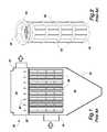
- FIG. 10is a side sectional view of an oblong filter cartridge constructed in accordance with a second embodiment of the invention, wherein the broken lines indicate discontinuous length;
- FIG. 11is a top plan view of the filter cartridge shown in FIG. 10 ;
- FIG. 12is a side elevation view, partially sectional, of the filter cartridge shown in FIGS. 10 & 11 ;
- FIG. 13is a side sectional view of an oblong filter cartridge constructed in accordance with a third embodiment of the invention, wherein the broken lines indicate discontinuous length;
- FIG. 14is a top plan view of the filter cartridge shown in FIG. 13 ;
- FIG. 15is a side elevation view, partially section, of the filter cartridge shown in FIGS. 13 & 14 ;
- FIG. 16is a side sectional view of an oblong filter cartridge constructed in accordance with a fourth embodiment of the invention, wherein the broken lines indicate discontinuous length;
- FIG. 17is a top plan view of the filter cartridge shown in FIG. 16 ;
- FIG. 18is a side elevation view, partially sectional, of the filter cartridge shown in FIGS. 16 & 17 ;
- FIG. 19is a schematic view illustrating the construction of a preferred compound curvature applied to the interior shoulder of the filter cartridge mouth
- FIG. 20is a fragmentary side elevational view of a filter cartridge similar to that shown in FIG. 13 but having a metal core with an imbedded grounding spring engaging the metal flange cap;
- FIG. 21is a fragmentary side elevational view, partially sectional, of a filter cartridge similar to that shown in FIGS. 5-9 but having a metal core and an external grounding wire;
- FIG. 22is a fragmentary side elevational view of the filter cartridge shown in FIG. 20 installed in the tube sheet of a baghouse.
- FIG. 1illustrates, somewhat schematically, the major components of a pulse-jet baghouse.
- a large sheet metal housing 30is divided by a horizontally support tube sheet 32 into a dirty air plenum 34 and a clean air plenum 36 .
- Vertically suspended through uniform openings in the tube sheet 32is a plurality of pleated filter cartridges 38 .
- Inlet ductwork 40delivers particulate laden gas to the dirty air plenum 34 .
- dustaccumulates on the exterior surface of the filters 38 .
- the scrubbed process gasis discharged from the clean air plenum 36 through an exhaust duct 42 to the atmosphere or to additional processing such as heat recovery equipment (not shown).
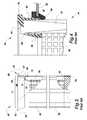
- FIGS. 2 & 3A typical prior art, cylindrical stepped-top filter cartridge 38 is illustrated in FIGS. 2 & 3 for application in uniform circular holes of a baghouse tube sheet 32 .
- the cartridge 38includes a central cylindrical core 50 formed by foraminous plastic. Circumscribing the central core 50 is a cylindrical ring of pleated filter media 52 . The combination of the pleated filter media 52 supported on the core 50 is commonly referred to as the pleat pack.
- a molded bottom end cap 54sealingly closes the lower ends of both the core 50 and filter media 52 of the pleat pack.
- the upper end of the pleat packis terminated with an open mouthed, molded top fitting 56 , the details of which as best seen in FIG. 3 .
- retaining bands 58are Intermediate the top fitting 56 and the bottom end cap 54 , retaining bands 58 , shown in FIG. 2 , spaced apart along the length of the filter cartridge 38 .
- the retaining bands 58serve to limit flexure of the pleated filter media 52 during a cleaning cycle.
- the top fitting 56has an upper annular flange 60 with an outer diameter greater than the hole diameter D in the tube sheet 32 .
- the insider diameter of the flange 60is less than the hole diameter D in the tube sheet 32 and forms the opening of the mouth into the filter cartridge 38 .
- a groove 62formed in the side wall 64 of the top fitting 56 .
- the groove 62is sized to substantially conform to the shape and diameter of the hole diameter D in the tube sheet 32 in order to seal therewith when the filter cartridge 38 is installed as shown.
- the side wall 64extends downwardly to integrally join a stepped portion 66 which overlies the pleat pack.
- a mold ridge 68 or series of bosses in the stepped portionresults from the portion of the central mold part that supports the pleat pack during the molding process.
- inner and outer skirts 70 & 72extend downwardly to form the inner and outer surfaces of the portion of the molding material that bonds to the core 50 and pleated filter media 52 .
- outer skirt 72forms the lower outside diameter of the top fitting and is slightly smaller in size than the diameter D of the tube sheet hole.
- the inner skirt 70forms the circular bore of the top fitting 56 and substantially corresponds to the inside diameter of the core 50 .
- the material of construction of the top fitting 56 and length of the side wall 64were of critical importance.
- the molding materialwas preferably a urethane having a durometer of between 30 to 70 shore A.
- the side wall 64was extended downwardly a sufficient length to satisfy the relationship of 0.3 ⁇ H/D ⁇ 0.85 where D was the diameter of the tube sheet hole and H was the distance between the peripheral groove and the top of the pleat pack encased in the molding material.
- FIG. 4Another typical prior art filter cartridge 74 is illustrated in FIG. 4 .
- the cartridge 74includes a central cylindrical core 50 of foraminous plastic which supports a cylindrical ring of pleated filter media 52 .
- a molded bottom end cap(not shown) sealingly closes the lower ends of both the core 50 and filter media 52 of the pleat pack.
- the upper end of the pleat packis terminated with an open mouthed, molded top fitting 76 , the details of which differ from those shown in FIGS. 2 & 3 .
- the top fitting 76has an upper annular flange 78 with an outer diameter greater than the hole diameter D in the tube sheet 32 .
- the inside diameter of the flange 60is less than the hole diameter D in the tube sheet 32 and forms the opening of the mouth into the filter cartridge 74 .
- a substantially straight side wall 80which throughout its length has a diameter smaller that the diameter of the tube sheet hole 82 .
- a stepped portion 84Interiorly of the mouth of the top fitting 76 and coincident with a portion of the flange 78 is a stepped portion 84 .
- the stepped portion 84commonly included a mold ridge 86 or series of bosses resulting from the portion of the central mold part that supported the pleat pack during the molding process.
- the inner skirt 88 of the top fitting 76be thickened which rendered the inside bore of the top fitting 76 smaller than the bore of the central core 50 .
- the pleat packextending upwardly almost to the flange 78 of the top fitting 76 .
- Thisprovided rigidity to the top fitting 76 that was necessary in order to seal the cartridge 74 to the tube sheet 32 .
- the tube sheet opening 82was fitted with an annular ring gasket 90 having a groove to receive the edges of the tube sheet opening 82 .
- the inside opening of the gasket 90was smaller than the diameter of the tube sheet opening 82 and also smaller than the outside diameter of the side wall 80 throughout most of its length.
- the gasket 90was fabricated from a resiliently deformable elastomeric.
- the region of the top fitting 76 beneath the flange 78would compress the gasket 90 between the side wall 80 and the edge of the tube sheet hole 82 and cause the bulbous lower end of the gasket 90 to be biased against the underside of the sube sheet to effect a seal.
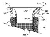
- the filter cartridge 100includes a central cylindrical core 102 formed by foraminous plastic. Circumscribing the central core 102 is a cylindrical ring of pleated filter media 104 which together with the support core 102 forms a pleat pack. A molded bottom end cap 106 sealingly closes the lower ends of both the core 102 and filter media 104 of the pleat pack. A groove 108 extends around the exterior of the end cap 106 from a ridge in the end cap mold (not shown) employed to center the pleat pack during the molding process. Similarly, a groove 110 or series of bosses are present in the lowermost surface of the end cap 106 from a ridge in the end cap mold employed to support the pleat pack during the molding process.
- the upper end of the pleat packis terminated with an open mouthed, molded top fitting 112 .
- Intermediate the top fitting 112 and the bottom end cap 106are retaining bands 114 spaced apart along the length of the filter cartridge 100 .
- the retaining bands 114serve to limit flexure of the pleated filter media 104 during a cleaning cycle.
- the top fitting 112has an upper annular flange 116 with an outer diameter greater than the hole diameter in the tube sheet 119 in which the filter cartridge 100 is to be installed as shown in FIGS. 8 & 9 .
- a contoured side wall 118which throughout its length has a diameter smaller that the hole diameter of the tube sheet 119 .
- the side wall 118includes a spiral thread 120 around the exterior surface thereof. Downwardly from the spiral thread 120 is a sealing gasket ridge 122 which transitions to the outer skirt 124 of the top fitting 112 .
- a rounded shoulder 126covering at least the thickness of the pleat pack and terminating in a throat 128 .
- the throat 128 of the top fitting 112substantially matches the inside bore of the circular core 102 .
- Three tapered holes 130resulting from tapered molding pins in the top fitting mold (not shown) employed to support the pleat pack during the molding process.
- six tapered holes on 60° angular incrementsmay be provided.
- the gasket 132is preferably fabricated from resiliently deformable elastomeric material.
- the sealing gasket 132includes an upper flange 134 to overlie the tube sheet 119 and a contoured cuff 136 to penetrate the hole through the tube sheet 119 .
- the side wall 118 and spiral thread 120pushes outwardly on the cuff 136 to seal against the inside bore of the hole through the tube sheet 119 .
- a twisting motion during installationwill permit the spiral thread 120 to assist in fully seating the filter cartridge 100 if a downward force is insufficient.
- an opposite twisting motion during removal of the filter cartridge 100will permit the spiral thread 120 to assist in the event the filter 100 and gasket 132 are seized to the tube sheet 119 .
- the molded spiral thread 120may be eliminated depending upon the operating conditions experienced.
- the side wall 118extends substantially straight downward from the flange 116 to the gasket locking ridge 122 .
- the locking ridge 122can engage the lower edge of the gasket cuff 136 to maintain a seal and to prevent the filter cartridge 100 from becoming dislodged.
- the top fitting 112may be fabricated from any suitable molding compound such as urethane, polyurethane, fluorocarbons, silicon compounds and the like. Rigid or flexible materials may be employed.
- the exterior surface of the top fitting 112includes some slight undercut features such as the spiral thread 120 and gasket locking ridge 122 . With these features included, the top fitting 112 may be preferably formed of a material having a durometer reading with 60 to 90 shore A. With such material, the fitting 112 can still be removed from a single piece external mold prior to being fully cured. This permits the top fitting 112 to be molded without vertical parting lines as has been necessary with prior art filters.
- the parting line of the top fitting 112consists of a line corresponding to the upper edge of the flange 116 . This region, of course, is not involved in the sealing function of the filter 100 to the tube sheet 119 and gasket 132 so the mold parting line of the fitting 112 represents no possible leakage source.
- the term oblongdescribes an elongate shape with semicircular ends, each end having the same diameter, and spaced apart parallel sides emanating from the semicircular ends.
- the filter cartridge 140includes an oblong central core 142 formed by foraminous plastic. Circumscribing the central core 142 is an oblong tube of pleated filter media 144 which together with the support core 142 forms a pleat pack. A molded bottom end cap 146 sealingly closes the lower ends of both the core 142 and filter media 144 of the pleat pack. A groove 148 , or series of bosses, is present in the lowermost surface of the end cap 146 from a ridge in the end cap mold (not shown) employed to support the pleat pack during the molding process.
- the upper end of the pleat packis terminated with an oblong, open mouthed, molded top fitting 150 .
- the top fitting 150has an oblong upper annular flange 152 which is sized to overlie the oblong hole in the tube sheet 154 in which the filter cartridge 140 is to be installed. Since the cross-sectional length of the oblong shape is much greater than the width thereof, the construction is strengthened with a metal collar 156 bonded to the molding material forming the top fitting 150 .
- the metal collar 156includes a flange portion 158 to overlie the tube sheet 154 and an integrally joined cuff 160 sized slightly smaller than the oblong opening in the tube sheet 154 in order to penetrate such opening.
- At opposite corners of the flange portion 158are provided holes 162 to receive threaded mounting bolts (not shown) for securing the metal collar 156 to the tube sheet 154 .
- a rounded shoulder 164covering at least the thickness of the pleat pack and terminating in an oblong throat 166 .
- the throat 166 of the top fitting 150substantially matches the inside oblong bore of the core 142 .
- tapered holes 168Spaced around the oblong shoulder 164 are tapered holes 168 resulting from tapered molding pins in the top fitting mold (not shown) employed to support the pleat pack during the molding process.
- an oblong compressible gasket 170is positioned between the upper surface of the tube sheet 154 and the underside of the flange portion 158 of the metal collar 156 .
- the metal collar 156may be biased to the tube sheet 154 with threaded bolts extending through the holes 162 , thus compressing the gasket 170 against the tube sheet 154 and forming a leak proof seal between the filter 140 and the tube sheet 154 .
- FIGS. 13-15are very similar to FIGS. 10-12 but illustrates a top fitting 172 with a modified metal collar 174 .
- the metal collar 174includes a flange portion 176 to overlie the tube sheet 154 and an integrally joined cuff 178 with a much reduced inner diameter than the metal collar 156 of FIGS. 10-12 . Accordingly, the cuff 178 and a portion of the flange 176 extend into the molding material forming the top fitting 172 but not so far as to interfere with the molding pins which support the pleat pack during the molding process. This configuration creates a strong bond between the molding material and the metal collar 174 .
- FIGS. 16-18are very similar to FIGS. 10-12 and to FIGS. 13-15 but illustrate a top fitting 180 with a further modified metal collar 182 .
- the metal collar 182includes a flange portion 184 to overlie the tube sheet 154 and an integrally joined cuff 186 with a much reduced inner diameter than the metal collar 156 of FIGS. 10-12 . Accordingly, the cuff 186 and a portion of the flange 184 extend into the molding material forming the top fitting 180 which creates a strong bond between the molding material and the metal collar 182 . In this modified construction, the cuff 186 extends downwardly a sufficient distance to engage the pleated filter media 144 of the pleat pack.
- the pleat packis supported on the edge of the cuff 186 .
- the top fittings 150 , 172 or 180 of FIGS. 10-18may be fabricated from any suitable molding compound such as urethane, polyurethane, fluorocarbons, silicon compounds and the like. Rigid or flexible materials may be employed, but typically more rigid materials are preferred and provide a better bond with metal collars used to reinforce the structural integrity of the top fitting. The presence of the metal collar in these top fittings require the use of a two part mold. However, the parting lines remain horizontal with respect to the top fitting so as to eliminate any vertical parting lines which might represent a potential leakage source.
- suitable molding compoundsuch as urethane, polyurethane, fluorocarbons, silicon compounds and the like.
- Rigid or flexible materialsmay be employed, but typically more rigid materials are preferred and provide a better bond with metal collars used to reinforce the structural integrity of the top fitting.
- the presence of the metal collar in these top fittingsrequire the use of a two part mold. However, the parting lines remain horizontal with respect to the top fitting so as to eliminate any vertical
- the metal collars of such filtersmay be incorporated in filters which are circular in cross-section such as those disclosed in FIGS. 5-9 .
- the cartridge filters constructed in accordance with this inventiontake the form of cylindrical filters as shown in FIGS. 5-9 or the form of oblong filters as shown in FIGS. 10-18 , the interior shape of the top fitting is critically important. In each instance, the interior is formed with a rounded shoulder as previously described to create a bell-shaped inlet mouth as an uninterrupted transition from the mouth opening to the bore of the support core within the filter cartridge.
- the rounded shoulder 126 or 164 of both the circular and oblong filter constructions previously describedtakes the form of a complex contoured surface of compound radii of curvatures.
- the compound radii of curvaturesrelate to the bore diameter D of the throat 128 of the top fitting 112 which corresponds closely to the bore of the structural core 102 . This relationship is illustrated in FIG. 19 .
- the initial opening of the mouth 188 of the top fitting 112extends from the flange 116 with a radius R 1 equal to 0.2 times the diameter D of the throat 128 .
- the center for the radius R 1is located a distance of 0.75D from the longitudinal centerline 190 of the top fitting 112 and a distance of 0.2D down from the plane 192 forming the initial opening of the mouth 188 .
- a second radius of curvature R 2 equal to D/3extends from a tangent to the radius R 1 to transition to the bore diameter D of the throat 128 .
- the center for the radius R 2is located a distance of 0.833D from the longitudinal centerline 190 of the top fitting 112 and a distance of 0.304D down from the plane 192 forming the initial opening of the mouth 188 .
- a circular filtermay have a bore diameter D equal to 3.6 inches.
- the initial opening of the mouth 188 of the top fitting 112extends from the flange 116 with a radius R 1 equal to 0.72 inches (0.2 ⁇ 3.6) centered at a distance of 2.70 inches (0.75 ⁇ 3.6) from the longitudinal centerline 190 of the top fitting 112 and a distance of 0.72 inches (0.2 ⁇ 3.6) down from the plane 192 forming the initial opening of the mouth 188 to a tangent with the second radius of curvature R 2 equal to 1.20 inches (3.6/3) centered at a distance of 3.00 inches (0.833 ⁇ 3.6) from the longitudinal centerline 190 of the top fitting 112 and a distance of 1.09 inches (0.304 ⁇ 3.6) down from the plane 192 forming the initial opening of the mouth 188 , to transition to the bore diameter D of the throat 128 .
- Filters constructed in accordance with the foregoing relationshipoffer surprising benefits. As determined by an independent testing laboratory comparing the bell-shaped mouth filter of this invention with a conventional stepped-top filter, the novel filter increases the available cleaning pressure by more than 10% and increases pulse-jet cleaning flow by 15% which yields a total cleaning power increase of more than 25%. Such performance is achieved without the additional pressure drop experienced during normal filtering operation when venturi equipment has been necessary to boost cleaning flow.
- the practical effects of increasing cleaning powerinclude lowering resistance during normal filtering through the filter cartridge and less frequent cleaning cycles for a given operating period. Thus, less compressed air is needed.
- the overall shapecomprises semicircular ends, each end having the same diameter, and spaced apart parallel sides emanating from the semicircular ends. If the sides of the oblong are spaced apart 1 inch and the overall length of the oblong is 4.6 inches, then D e equals 3.61 inches [( ⁇ 1+2 ⁇ 4.6 ⁇ 1)/ ⁇ ]. In the case of an oblong, therefore, D e is used in the place of D as illustrated in FIG. 19 .
- the radius R 1equals 0.72 inches (0.2 ⁇ 3.61) centered a distance 0.72 inches (0.2D e ) down from the plane forming the initial opening of the mouth and a distance of 0.083D e from the bore (i.e., distance between the sides of the oblong) to a tangent with the second radius of curvature R 2 equal to 1.20 inches (3.61/3) centered at a distance of 1.10 inches (0.304D e ) down from the plane forming the initial opening of the mouth and a distance of 1.70 inches (bore/2+R 2 ) from the longitudinal centerline to transition to the bore of the throat.
- filter cartridges of this inventionmay be modified to include metallic cores and electrical grounds.
- FIG. 20illustrates a filter construction similar to FIGS. 13-15 but having a metallic core 194 .
- a metal spring clip 196is spot welded to the core 194 and, during the molding process, is embedded in the molding compound forming the top fitting 172 .
- the spring clip 196is biased to engagement with the inside surface of the cuff 178 of the metal collar 174 .
- the flange portion 176contacts the surface of the tube sheet 154 thereby establishing an electrical ground from the tube sheet 154 , through the metal collar 174 , and through the spring clip 196 to the core 194 .
- FIGS. 21 & 22illustrate a filter construction similar to FIGS. 5-9 but having a metallic core 198 .
- a grounding wire 200is attached to the core 198 and, during the molding process, is threaded through the molding compound forming the top fitting 112 .
- the grounding wire 200is threaded between the top fitting 112 and the sealing gasket 132 to be connected to the tube sheet 119 , or other grounding equipment of the baghouse.
Landscapes
- Chemical & Material Sciences (AREA)
- Chemical Kinetics & Catalysis (AREA)
- Physics & Mathematics (AREA)
- Geometry (AREA)
- Filtering Of Dispersed Particles In Gases (AREA)
Abstract
Description
Claims (18)
Priority Applications (1)
| Application Number | Priority Date | Filing Date | Title |
|---|---|---|---|
| US13/011,757US8580004B1 (en) | 2011-01-21 | 2011-01-21 | Unitary filter cartridge with flow transition mouth |
Applications Claiming Priority (1)
| Application Number | Priority Date | Filing Date | Title |
|---|---|---|---|
| US13/011,757US8580004B1 (en) | 2011-01-21 | 2011-01-21 | Unitary filter cartridge with flow transition mouth |
Publications (1)
| Publication Number | Publication Date |
|---|---|
| US8580004B1true US8580004B1 (en) | 2013-11-12 |
Family
ID=49517985
Family Applications (1)
| Application Number | Title | Priority Date | Filing Date |
|---|---|---|---|
| US13/011,757Active2031-08-23US8580004B1 (en) | 2011-01-21 | 2011-01-21 | Unitary filter cartridge with flow transition mouth |
Country Status (1)
| Country | Link |
|---|---|
| US (1) | US8580004B1 (en) |
Cited By (14)
| Publication number | Priority date | Publication date | Assignee | Title |
|---|---|---|---|---|
| WO2015168505A1 (en)* | 2014-05-02 | 2015-11-05 | Donaldson Company, Inc. | Fluid filter housing assembly |
| KR101607929B1 (en) | 2015-05-15 | 2016-04-11 | 오근서 | a filter cartridge and a dust collector |
| US9616371B1 (en) | 2014-05-06 | 2017-04-11 | iFil USA, LLC | Cartridge filter with flow transition insert |
| US20180050294A1 (en)* | 2016-08-22 | 2018-02-22 | Carl Freudenberg Kg | Filter cartridge and filter cartridge arrangement |
| US20190374892A1 (en)* | 2018-06-11 | 2019-12-12 | Imperial Systems, Inc. | Cartridges for Vertically Oriented Dust Collectors |
| EP3680003A1 (en)* | 2019-01-10 | 2020-07-15 | Carl Freudenberg KG | Filter cartridge with venturi nozzle |
| US10773202B2 (en)* | 2016-03-02 | 2020-09-15 | Donaldson Company, Inc. | Filter element having inner support and methods |
| USD915564S1 (en) | 2019-02-08 | 2021-04-06 | Donaldson Company, Inc. | End cap seal |
| US11090596B2 (en)* | 2016-07-07 | 2021-08-17 | BHA Altair. LLC | Variable diameter top for a filter element |
| US20210260607A1 (en)* | 2020-02-24 | 2021-08-26 | Altair (UK) Limited | Pulse nozzle for filter cleaning systems |
| CN114100275A (en)* | 2021-09-01 | 2022-03-01 | 九江七所精密机电科技有限公司 | Lifting type filter element socket dustproof device for filter |
| US11344833B2 (en)* | 2015-10-05 | 2022-05-31 | Parker-Hannifin Corporation | Filter securing mechanism and attachment method |
| US20240246778A1 (en)* | 2023-01-23 | 2024-07-25 | Rheo Engineering | Receiver for a vacuum conveyance system |
| EP4431173A1 (en) | 2023-03-16 | 2024-09-18 | Carl Freudenberg KG | Filter cartridge with a plurality of filter elements |
Citations (100)
| Publication number | Priority date | Publication date | Assignee | Title |
|---|---|---|---|---|
| US1012122A (en) | 1911-03-17 | 1911-12-19 | Alfred Budil | Air-filter. |
| GB160168A (en) | 1920-03-12 | 1921-08-04 | Adolf Kaempf | A process and apparatus for the manufacture of glass-nozzles for the spinning of artificial fibres, horse-hair, straw and the like |
| GB213930A (en) | 1923-04-06 | 1925-07-07 | Arthur George Lloyd Neighbour | Improvements in magneto electric ignition machines |
| GB242388A (en) | 1924-09-12 | 1925-11-12 | Charles Laurence Burdick | Improvements in purifier for air or gas |
| DE488891C (en) | 1926-12-03 | 1930-01-10 | I G Farbenindustrie Akt Ges | Process for the preparation of N-substituted arsenobenzimidazolones |
| US1743934A (en) | 1924-11-26 | 1930-01-14 | Ruemelin Richard | Dust separator |
| US1847368A (en) | 1926-05-14 | 1932-03-01 | Nat Aniline & Chem Co Inc | Dust separation |
| US2072906A (en) | 1933-08-11 | 1937-03-09 | Pangborn Corp | Filtering and collecting apparatus |
| GB520737A (en) | 1937-10-29 | 1940-05-02 | Tecalemit Ltd | Means for automatically controlling the filling of reservoirs, tanks and the like |
| US2308310A (en) | 1942-05-07 | 1943-01-12 | Richard Ruemelin | Filter bag attaching means for dust arresting apparatus |
| US2308309A (en) | 1940-12-26 | 1943-01-12 | Ruemelin | Dust arresting apparatus |
| US2335315A (en) | 1941-01-10 | 1943-11-30 | United Shoe Machinery Corp | Dust separating system |
| US2503568A (en) | 1944-09-25 | 1950-04-11 | Timm Aircraft Corp | Vacuum cleaner |
| GB636439A (en) | 1948-02-06 | 1950-04-26 | Cyril Gauntlett | Strainers for tea, coffee and like pots or containers |
| US2927659A (en) | 1955-03-02 | 1960-03-08 | Walter W Pabst | Dust collector |
| GB840570A (en) | 1958-01-01 | 1960-07-06 | Vokes Ltd | Improvements in filter elements |
| US2952332A (en) | 1957-12-09 | 1960-09-13 | Parsons Engineering Corp | Dust collector cup |
| US2981368A (en) | 1959-06-08 | 1961-04-25 | Anthony L Johnson | Filter tube |
| US3167415A (en) | 1959-11-02 | 1965-01-26 | Nailsea Engineering Company Lt | Cleaning devices for gas filtering apparatus |
| US3170777A (en) | 1961-08-14 | 1965-02-23 | Ducon Co | Mounting for filter tubes |
| DE1191078B (en) | 1959-07-10 | 1965-04-15 | Holland Electro C V | Vacuum cleaner with a housing closed by a cover, in which there is a closed dust bag |
| GB990587A (en) | 1962-09-25 | 1965-04-28 | Dust Control Equipment Ltd | Improvements in gas filtering apparatus |
| GB1016556A (en) | 1963-12-03 | 1966-01-12 | Dust Control Equipment Ltd | Improved gas filtering apparatus |
| US3243940A (en) | 1961-10-13 | 1966-04-05 | Phillips Petroleum Co | Bag filtering process and apparatus |
| GB1081516A (en) | 1965-08-26 | 1967-08-31 | Dust Control Equipment Ltd | An improvement in gas filtering apparatus |
| US3421295A (en) | 1962-07-27 | 1969-01-14 | Dust Control Equipment Ltd | Gas filtering apparatus |
| US3524304A (en) | 1960-06-10 | 1970-08-18 | Delbag Luftfilter Gmbh | Bag air-filter |
| US3550359A (en) | 1968-11-29 | 1970-12-29 | Fuller Co | Filter bag clamping apparatus |
| US3716436A (en) | 1970-03-16 | 1973-02-13 | Pall Corp | Process for making a back pressure resistant filter element |
| US3747305A (en) | 1971-04-16 | 1973-07-24 | American Air Filter Co | Tubular gas filter apparatus |
| US3765152A (en) | 1970-11-04 | 1973-10-16 | Gen Resource Corp | Cleaning of filtering media |
| US3774769A (en) | 1971-11-22 | 1973-11-27 | Gaf Corp | Liquid filter pressurized apparatus |
| US3774458A (en) | 1971-11-18 | 1973-11-27 | Seiko Koki Kk | Actuator device for use with an interval timer |
| US3791111A (en) | 1973-04-30 | 1974-02-12 | G Kroll | Filter device |
| US3826066A (en) | 1971-07-16 | 1974-07-30 | Summit Filter Corp | Double-wall filter bag construction |
| US3830042A (en) | 1972-09-13 | 1974-08-20 | Allied Filter Eng Inc | Rectangular filter bag |
| US3837151A (en) | 1972-11-17 | 1974-09-24 | R Jensen | Baghouse dust collector |
| US3844750A (en)* | 1973-03-28 | 1974-10-29 | Flex Kleen Corp | Dust collector bag mounting arrangement |
| US3853509A (en) | 1973-05-04 | 1974-12-10 | R Leliaert | Bag type filter device |
| US3876402A (en) | 1972-09-28 | 1975-04-08 | Standard Havens | Apparatus for separating particulate matter from a gas stream |
| US3942962A (en) | 1974-05-08 | 1976-03-09 | U.S. Filter Company | Pulse jet and venturi liner |
| US3997305A (en) | 1976-03-05 | 1976-12-14 | Flex-Kleen Corporation | Support for bottom removal dust collector bag assembly |
| US4007026A (en) | 1975-08-13 | 1977-02-08 | Fmc Corporation | Compact dust filter system |
| US4073632A (en) | 1975-07-07 | 1978-02-14 | United States Filter Corporation | Filter bag assembly |
| US4105421A (en) | 1976-05-28 | 1978-08-08 | Standard Havens, Inc. | Disposable filter cartridge |
| US4159197A (en) | 1977-10-05 | 1979-06-26 | Donaldson Company, Inc. | Suspension gasket seal and system for baghouse filter units |
| US4187091A (en) | 1977-05-16 | 1980-02-05 | Donaldson Company, Inc. | Pleated paper filter cartridge |
| US4218227A (en) | 1975-07-28 | 1980-08-19 | Donaldson Company, Inc. | Dust collector |
| US4219343A (en) | 1979-04-04 | 1980-08-26 | Joy Manufacturing Company | Filter bag retaining system with removable thimble extension |
| US4247314A (en) | 1979-07-25 | 1981-01-27 | Flex-Kleen Corporation | Mechanical filter bag shaker assembly |
| US4256473A (en) | 1979-10-05 | 1981-03-17 | The Spencer Turbine Company | Filter bag attaching means |
| US4270935A (en) | 1977-06-27 | 1981-06-02 | United States Filter Corporation | Filter assembly for high temperature glass fiber filter media |
| US4272263A (en) | 1979-05-21 | 1981-06-09 | American Air Filter Company, Inc. | Filter arrangement |
| US4276069A (en) | 1979-09-12 | 1981-06-30 | American Air Filter Company, Inc. | Filter arrangement |
| US4292057A (en) | 1975-09-29 | 1981-09-29 | Flex Kleen Corp. | Top removal support for dust collector bags |
| US4291904A (en) | 1977-10-24 | 1981-09-29 | Arkay Packaging Corporation | Filter holder |
| US4312648A (en) | 1980-12-08 | 1982-01-26 | American Air Filter Company, Inc. | Pocket filter arrangement |
| US4319897A (en) | 1980-06-16 | 1982-03-16 | Farr Company | Air filter assembly including an improved jet pump cleaning apparatus |
| US4322231A (en) | 1980-06-16 | 1982-03-30 | Farr Company | Filter element locking mechanism |
| US4344781A (en) | 1981-02-03 | 1982-08-17 | United States Filter Corporation | Filter bag with protective cuff |
| US4424070A (en) | 1982-11-22 | 1984-01-03 | Flex-Kleen Corporation | Dust collecting filter cartridge and attachment structure for suspending same from baghouse tube sheet |
| US4436536A (en)* | 1982-09-29 | 1984-03-13 | Flex-Kleen Corporation | Dust collecting filter cartridge and attachment structure for suspending same from baghouse tube sheet |
| US4443237A (en) | 1982-11-22 | 1984-04-17 | Flex-Kleen Corporation | Dust collecting filter cartridge and attachment structure for suspending same from baghouse tube sheet |
| US4445915A (en) | 1982-08-16 | 1984-05-01 | Flex-Kleen Corporation | Dust collector filter cartridge and attachment means for suspending same from baghouse tube sheet |
| US4560477A (en) | 1982-11-22 | 1985-12-24 | 501 P.M. Filter Konstruktionen | Separator for filter cartridges |
| US4632680A (en) | 1985-10-28 | 1986-12-30 | Carter-Day Co. | Planar sided air shaping inserts for filter bags |
| US4655806A (en) | 1985-12-23 | 1987-04-07 | Griffin Environmental Company, Inc. | Dust separator |
| US4663041A (en) | 1983-09-09 | 1987-05-05 | Kurashiki Baseki Kabushiki Kaisha | Fluorocarbon filter element |
| US4732678A (en) | 1986-05-01 | 1988-03-22 | Wix Corporation | Filter body having closely adjacent filter material |
| GB2195558A (en) | 1986-10-09 | 1988-04-13 | Tsukasa Kasei Kogyo | Bag filter |
| US4813985A (en) | 1984-07-13 | 1989-03-21 | Bha Group, Inc. | Tensioning device for bag filters |
| US4878930A (en) | 1984-03-15 | 1989-11-07 | W. L. Gore & Associates, Inc. | Filter cartridge |
| US4929354A (en) | 1982-05-28 | 1990-05-29 | Cuno, Incorporated | Filter element having microporous membrane |
| US4954255A (en) | 1988-04-02 | 1990-09-04 | S.F. Muller & Partner | Filtering apparatus with pleated filtering material |
| US5074896A (en) | 1989-12-29 | 1991-12-24 | Jacques Baert | Cartridge device for gas filtration |
| US5173098A (en) | 1991-12-18 | 1992-12-22 | Pipkorn Environmental Technologies, Inc. | Wire filter cage |
| US5207812A (en) | 1992-05-08 | 1993-05-04 | W. L. Gore & Associates, Inc. | Filter cartridge |
| US5207811A (en) | 1992-07-08 | 1993-05-04 | Dana Corporation | Air filter sealing groove |
| US5211846A (en) | 1990-07-30 | 1993-05-18 | Pleatco Electronic & Filter Corp. | Replacement filter cartridge assembly |
| US5222488A (en) | 1991-07-11 | 1993-06-29 | Donaldson Company, Inc. | Respirator air filter cartridge with a replaceable filter element |
| US5290441A (en) | 1991-08-26 | 1994-03-01 | Hosokawa Micron International Inc. | Integrated collar, filter bag, cage and locking ring assembly for baghouses |
| US5290446A (en) | 1992-06-10 | 1994-03-01 | Pall Corporation | Helical wrapped filter element |
| US5308369A (en) | 1993-04-28 | 1994-05-03 | Griffin Environmental Company, Inc. | Snap-in filter bag assembly for bottom loading in dust collector |
| US5336405A (en) | 1990-04-20 | 1994-08-09 | Minnesota Mining And Manufacturing Company | Filter cartridge end cap assembly |
| US5536290A (en) | 1995-02-17 | 1996-07-16 | W. L. Gore & Associates, Inc. | Pleated cartridge filter attachment for top loading filter assemblies |
| US5632791A (en) | 1994-12-06 | 1997-05-27 | Bha Group, Inc. | Unitary filter cartridge |
| US5730766A (en)* | 1996-11-05 | 1998-03-24 | Bha Group, Inc. | Non-round unitary filter cartridge |
| US5746792A (en) | 1996-10-25 | 1998-05-05 | Bha Group Holdings, Inc. | Dust collector filter element and supporting structure |
| US6203591B1 (en) | 1998-09-30 | 2001-03-20 | Bha Group Holdings, Inc. | Baghouse, long filter assembly and method of installation |
| US6358292B1 (en) | 2000-06-02 | 2002-03-19 | Bha Group Holdings, Inc. | Pleated filter element with reusable mounting plate |
| US6375698B1 (en) | 1998-09-30 | 2002-04-23 | Bha Group Holdings, Inc. | Long filter assembly with connection device |
| GB0213930D0 (en) | 2002-06-18 | 2002-07-31 | Bird Raymond F | Airing cupboard space saver |
| US6440188B1 (en) | 2000-07-07 | 2002-08-27 | Bha Group, Holdings, Inc. | Air filter assembly capable of top and bottom loading |
| US20030089234A1 (en)* | 2000-01-31 | 2003-05-15 | Odd Bjarno | Method when cleaning a filter |
| US6726735B1 (en) | 1994-05-06 | 2004-04-27 | Bha Group Holdings, Inc. | Unitary filter cartridge |
| US20040237483A1 (en)* | 2003-05-30 | 2004-12-02 | Bha Group Holdings Inc. | Filter cartridge mounting structure |
| GB0520737D0 (en) | 2005-10-12 | 2005-11-23 | Byrne Charles M | The preparation of olive oil |
| US7186284B2 (en) | 2004-02-13 | 2007-03-06 | Bha Group, Inc. | Filter mounting system |
| US7585343B2 (en) | 2006-07-26 | 2009-09-08 | General Electric Company | Filter cleaning system and method |
| USD626208S1 (en) | 2010-02-08 | 2010-10-26 | iFil USA, LLC | Cartridge filter gasket |
- 2011
- 2011-01-21USUS13/011,757patent/US8580004B1/enactiveActive
Patent Citations (105)
| Publication number | Priority date | Publication date | Assignee | Title |
|---|---|---|---|---|
| US1012122A (en) | 1911-03-17 | 1911-12-19 | Alfred Budil | Air-filter. |
| GB160168A (en) | 1920-03-12 | 1921-08-04 | Adolf Kaempf | A process and apparatus for the manufacture of glass-nozzles for the spinning of artificial fibres, horse-hair, straw and the like |
| GB213930A (en) | 1923-04-06 | 1925-07-07 | Arthur George Lloyd Neighbour | Improvements in magneto electric ignition machines |
| GB242388A (en) | 1924-09-12 | 1925-11-12 | Charles Laurence Burdick | Improvements in purifier for air or gas |
| US1743934A (en) | 1924-11-26 | 1930-01-14 | Ruemelin Richard | Dust separator |
| US1847368A (en) | 1926-05-14 | 1932-03-01 | Nat Aniline & Chem Co Inc | Dust separation |
| DE488891C (en) | 1926-12-03 | 1930-01-10 | I G Farbenindustrie Akt Ges | Process for the preparation of N-substituted arsenobenzimidazolones |
| US2072906A (en) | 1933-08-11 | 1937-03-09 | Pangborn Corp | Filtering and collecting apparatus |
| GB520737A (en) | 1937-10-29 | 1940-05-02 | Tecalemit Ltd | Means for automatically controlling the filling of reservoirs, tanks and the like |
| US2308309A (en) | 1940-12-26 | 1943-01-12 | Ruemelin | Dust arresting apparatus |
| US2335315A (en) | 1941-01-10 | 1943-11-30 | United Shoe Machinery Corp | Dust separating system |
| US2308310A (en) | 1942-05-07 | 1943-01-12 | Richard Ruemelin | Filter bag attaching means for dust arresting apparatus |
| US2503568A (en) | 1944-09-25 | 1950-04-11 | Timm Aircraft Corp | Vacuum cleaner |
| GB636439A (en) | 1948-02-06 | 1950-04-26 | Cyril Gauntlett | Strainers for tea, coffee and like pots or containers |
| US2927659A (en) | 1955-03-02 | 1960-03-08 | Walter W Pabst | Dust collector |
| US2952332A (en) | 1957-12-09 | 1960-09-13 | Parsons Engineering Corp | Dust collector cup |
| GB840570A (en) | 1958-01-01 | 1960-07-06 | Vokes Ltd | Improvements in filter elements |
| US2981368A (en) | 1959-06-08 | 1961-04-25 | Anthony L Johnson | Filter tube |
| DE1191078B (en) | 1959-07-10 | 1965-04-15 | Holland Electro C V | Vacuum cleaner with a housing closed by a cover, in which there is a closed dust bag |
| US3167415A (en) | 1959-11-02 | 1965-01-26 | Nailsea Engineering Company Lt | Cleaning devices for gas filtering apparatus |
| US3524304A (en) | 1960-06-10 | 1970-08-18 | Delbag Luftfilter Gmbh | Bag air-filter |
| US3170777A (en) | 1961-08-14 | 1965-02-23 | Ducon Co | Mounting for filter tubes |
| US3243940A (en) | 1961-10-13 | 1966-04-05 | Phillips Petroleum Co | Bag filtering process and apparatus |
| US3421295A (en) | 1962-07-27 | 1969-01-14 | Dust Control Equipment Ltd | Gas filtering apparatus |
| GB990587A (en) | 1962-09-25 | 1965-04-28 | Dust Control Equipment Ltd | Improvements in gas filtering apparatus |
| GB1016556A (en) | 1963-12-03 | 1966-01-12 | Dust Control Equipment Ltd | Improved gas filtering apparatus |
| GB1081516A (en) | 1965-08-26 | 1967-08-31 | Dust Control Equipment Ltd | An improvement in gas filtering apparatus |
| US3550359A (en) | 1968-11-29 | 1970-12-29 | Fuller Co | Filter bag clamping apparatus |
| US3716436A (en) | 1970-03-16 | 1973-02-13 | Pall Corp | Process for making a back pressure resistant filter element |
| US3765152A (en) | 1970-11-04 | 1973-10-16 | Gen Resource Corp | Cleaning of filtering media |
| US3747305A (en) | 1971-04-16 | 1973-07-24 | American Air Filter Co | Tubular gas filter apparatus |
| US3826066A (en) | 1971-07-16 | 1974-07-30 | Summit Filter Corp | Double-wall filter bag construction |
| US3774458A (en) | 1971-11-18 | 1973-11-27 | Seiko Koki Kk | Actuator device for use with an interval timer |
| US3774769A (en) | 1971-11-22 | 1973-11-27 | Gaf Corp | Liquid filter pressurized apparatus |
| US3830042A (en) | 1972-09-13 | 1974-08-20 | Allied Filter Eng Inc | Rectangular filter bag |
| US3876402A (en) | 1972-09-28 | 1975-04-08 | Standard Havens | Apparatus for separating particulate matter from a gas stream |
| US3837151A (en) | 1972-11-17 | 1974-09-24 | R Jensen | Baghouse dust collector |
| US3844750A (en)* | 1973-03-28 | 1974-10-29 | Flex Kleen Corp | Dust collector bag mounting arrangement |
| US3791111A (en) | 1973-04-30 | 1974-02-12 | G Kroll | Filter device |
| US3853509A (en) | 1973-05-04 | 1974-12-10 | R Leliaert | Bag type filter device |
| US3942962A (en) | 1974-05-08 | 1976-03-09 | U.S. Filter Company | Pulse jet and venturi liner |
| US4073632A (en) | 1975-07-07 | 1978-02-14 | United States Filter Corporation | Filter bag assembly |
| US4218227A (en) | 1975-07-28 | 1980-08-19 | Donaldson Company, Inc. | Dust collector |
| US4007026A (en) | 1975-08-13 | 1977-02-08 | Fmc Corporation | Compact dust filter system |
| US4292057A (en) | 1975-09-29 | 1981-09-29 | Flex Kleen Corp. | Top removal support for dust collector bags |
| US3997305A (en) | 1976-03-05 | 1976-12-14 | Flex-Kleen Corporation | Support for bottom removal dust collector bag assembly |
| US4105421A (en) | 1976-05-28 | 1978-08-08 | Standard Havens, Inc. | Disposable filter cartridge |
| US4187091A (en) | 1977-05-16 | 1980-02-05 | Donaldson Company, Inc. | Pleated paper filter cartridge |
| US4270935A (en) | 1977-06-27 | 1981-06-02 | United States Filter Corporation | Filter assembly for high temperature glass fiber filter media |
| US4159197A (en) | 1977-10-05 | 1979-06-26 | Donaldson Company, Inc. | Suspension gasket seal and system for baghouse filter units |
| US4291904A (en) | 1977-10-24 | 1981-09-29 | Arkay Packaging Corporation | Filter holder |
| US4219343A (en) | 1979-04-04 | 1980-08-26 | Joy Manufacturing Company | Filter bag retaining system with removable thimble extension |
| US4272263A (en) | 1979-05-21 | 1981-06-09 | American Air Filter Company, Inc. | Filter arrangement |
| US4247314A (en) | 1979-07-25 | 1981-01-27 | Flex-Kleen Corporation | Mechanical filter bag shaker assembly |
| US4276069A (en) | 1979-09-12 | 1981-06-30 | American Air Filter Company, Inc. | Filter arrangement |
| US4256473A (en) | 1979-10-05 | 1981-03-17 | The Spencer Turbine Company | Filter bag attaching means |
| US4319897A (en) | 1980-06-16 | 1982-03-16 | Farr Company | Air filter assembly including an improved jet pump cleaning apparatus |
| US4322231A (en) | 1980-06-16 | 1982-03-30 | Farr Company | Filter element locking mechanism |
| US4312648A (en) | 1980-12-08 | 1982-01-26 | American Air Filter Company, Inc. | Pocket filter arrangement |
| US4344781A (en) | 1981-02-03 | 1982-08-17 | United States Filter Corporation | Filter bag with protective cuff |
| US4929354A (en) | 1982-05-28 | 1990-05-29 | Cuno, Incorporated | Filter element having microporous membrane |
| US4445915A (en) | 1982-08-16 | 1984-05-01 | Flex-Kleen Corporation | Dust collector filter cartridge and attachment means for suspending same from baghouse tube sheet |
| US4436536A (en)* | 1982-09-29 | 1984-03-13 | Flex-Kleen Corporation | Dust collecting filter cartridge and attachment structure for suspending same from baghouse tube sheet |
| US4424070A (en) | 1982-11-22 | 1984-01-03 | Flex-Kleen Corporation | Dust collecting filter cartridge and attachment structure for suspending same from baghouse tube sheet |
| US4443237A (en) | 1982-11-22 | 1984-04-17 | Flex-Kleen Corporation | Dust collecting filter cartridge and attachment structure for suspending same from baghouse tube sheet |
| US4560477A (en) | 1982-11-22 | 1985-12-24 | 501 P.M. Filter Konstruktionen | Separator for filter cartridges |
| US4663041A (en) | 1983-09-09 | 1987-05-05 | Kurashiki Baseki Kabushiki Kaisha | Fluorocarbon filter element |
| US4878930A (en) | 1984-03-15 | 1989-11-07 | W. L. Gore & Associates, Inc. | Filter cartridge |
| US4813985A (en) | 1984-07-13 | 1989-03-21 | Bha Group, Inc. | Tensioning device for bag filters |
| US4632680A (en) | 1985-10-28 | 1986-12-30 | Carter-Day Co. | Planar sided air shaping inserts for filter bags |
| US4655806A (en) | 1985-12-23 | 1987-04-07 | Griffin Environmental Company, Inc. | Dust separator |
| US4732678A (en) | 1986-05-01 | 1988-03-22 | Wix Corporation | Filter body having closely adjacent filter material |
| GB2195558A (en) | 1986-10-09 | 1988-04-13 | Tsukasa Kasei Kogyo | Bag filter |
| US4954255A (en) | 1988-04-02 | 1990-09-04 | S.F. Muller & Partner | Filtering apparatus with pleated filtering material |
| US5074896A (en) | 1989-12-29 | 1991-12-24 | Jacques Baert | Cartridge device for gas filtration |
| US5336405A (en) | 1990-04-20 | 1994-08-09 | Minnesota Mining And Manufacturing Company | Filter cartridge end cap assembly |
| US5211846A (en) | 1990-07-30 | 1993-05-18 | Pleatco Electronic & Filter Corp. | Replacement filter cartridge assembly |
| US5222488A (en) | 1991-07-11 | 1993-06-29 | Donaldson Company, Inc. | Respirator air filter cartridge with a replaceable filter element |
| US5290441A (en) | 1991-08-26 | 1994-03-01 | Hosokawa Micron International Inc. | Integrated collar, filter bag, cage and locking ring assembly for baghouses |
| US5173098A (en) | 1991-12-18 | 1992-12-22 | Pipkorn Environmental Technologies, Inc. | Wire filter cage |
| US5207812A (en) | 1992-05-08 | 1993-05-04 | W. L. Gore & Associates, Inc. | Filter cartridge |
| US5207812B1 (en) | 1992-05-08 | 1996-10-01 | Gore & Ass | Filter cartridge |
| US5290446A (en) | 1992-06-10 | 1994-03-01 | Pall Corporation | Helical wrapped filter element |
| US5207811A (en) | 1992-07-08 | 1993-05-04 | Dana Corporation | Air filter sealing groove |
| US5308369A (en) | 1993-04-28 | 1994-05-03 | Griffin Environmental Company, Inc. | Snap-in filter bag assembly for bottom loading in dust collector |
| US5885314A (en) | 1994-05-06 | 1999-03-23 | Bha Group Holdings, Inc. | Unitary filter cartridge |
| US6726735B1 (en) | 1994-05-06 | 2004-04-27 | Bha Group Holdings, Inc. | Unitary filter cartridge |
| US6017378A (en) | 1994-05-06 | 2000-01-25 | Bha Group Holdings, Inc. | Unitary filter cartridge |
| US5632791A (en) | 1994-12-06 | 1997-05-27 | Bha Group, Inc. | Unitary filter cartridge |
| US5536290A (en) | 1995-02-17 | 1996-07-16 | W. L. Gore & Associates, Inc. | Pleated cartridge filter attachment for top loading filter assemblies |
| US5746792A (en) | 1996-10-25 | 1998-05-05 | Bha Group Holdings, Inc. | Dust collector filter element and supporting structure |
| US5730766A (en)* | 1996-11-05 | 1998-03-24 | Bha Group, Inc. | Non-round unitary filter cartridge |
| US6203591B1 (en) | 1998-09-30 | 2001-03-20 | Bha Group Holdings, Inc. | Baghouse, long filter assembly and method of installation |
| US6375698B1 (en) | 1998-09-30 | 2002-04-23 | Bha Group Holdings, Inc. | Long filter assembly with connection device |
| US20030089234A1 (en)* | 2000-01-31 | 2003-05-15 | Odd Bjarno | Method when cleaning a filter |
| US6358292B1 (en) | 2000-06-02 | 2002-03-19 | Bha Group Holdings, Inc. | Pleated filter element with reusable mounting plate |
| US6440188B1 (en) | 2000-07-07 | 2002-08-27 | Bha Group, Holdings, Inc. | Air filter assembly capable of top and bottom loading |
| US6676722B1 (en) | 2000-07-07 | 2004-01-13 | Bha Group, Inc. | Air filter assembly capable of top and bottom loading |
| GB0213930D0 (en) | 2002-06-18 | 2002-07-31 | Bird Raymond F | Airing cupboard space saver |
| US20040237483A1 (en)* | 2003-05-30 | 2004-12-02 | Bha Group Holdings Inc. | Filter cartridge mounting structure |
| US6858052B2 (en) | 2003-05-30 | 2005-02-22 | Bha Group, Inc. | Filter cartridge mounting structure |
| US7186284B2 (en) | 2004-02-13 | 2007-03-06 | Bha Group, Inc. | Filter mounting system |
| GB0520737D0 (en) | 2005-10-12 | 2005-11-23 | Byrne Charles M | The preparation of olive oil |
| US7585343B2 (en) | 2006-07-26 | 2009-09-08 | General Electric Company | Filter cleaning system and method |
| USD626208S1 (en) | 2010-02-08 | 2010-10-26 | iFil USA, LLC | Cartridge filter gasket |
Non-Patent Citations (4)
| Title |
|---|
| Kleisser Company Operating and Maintenance Manual. |
| Poly Sump & Sweage Basins; AK Industries Inc., Jun. 2002, p. 10. |
| WAM GmbH Dust Collectors Literature, 035/94.1. |
| WAMECO Spart Parts, p.03505.R.24. |
Cited By (27)
| Publication number | Priority date | Publication date | Assignee | Title |
|---|---|---|---|---|
| WO2015168505A1 (en)* | 2014-05-02 | 2015-11-05 | Donaldson Company, Inc. | Fluid filter housing assembly |
| US9616371B1 (en) | 2014-05-06 | 2017-04-11 | iFil USA, LLC | Cartridge filter with flow transition insert |
| KR101607929B1 (en) | 2015-05-15 | 2016-04-11 | 오근서 | a filter cartridge and a dust collector |
| US11344833B2 (en)* | 2015-10-05 | 2022-05-31 | Parker-Hannifin Corporation | Filter securing mechanism and attachment method |
| US20220118393A1 (en)* | 2016-03-02 | 2022-04-21 | Donaldson Company, Inc. | Filter element having inner support and methods |
| US11712650B2 (en)* | 2016-03-02 | 2023-08-01 | Donaldson Company, Inc. | Filter element having inner support and methods |
| US12145094B2 (en)* | 2016-03-02 | 2024-11-19 | Donaldson Company, Inc. | Filter element having inner support and methods |
| US10773202B2 (en)* | 2016-03-02 | 2020-09-15 | Donaldson Company, Inc. | Filter element having inner support and methods |
| US20240139666A1 (en)* | 2016-03-02 | 2024-05-02 | Donaldson Company, Inc. | Filter element having inner support and methods |
| US11167235B2 (en)* | 2016-03-02 | 2021-11-09 | Donaldson Company, Inc. | Filter element having inner support and methods |
| US11090596B2 (en)* | 2016-07-07 | 2021-08-17 | BHA Altair. LLC | Variable diameter top for a filter element |
| GB2556144A (en)* | 2016-08-22 | 2018-05-23 | Freudenberg Carl Kg | Filter cartridge and filter cartridge arrangement |
| GB2556144B (en)* | 2016-08-22 | 2021-04-07 | Freudenberg Carl Kg | Filter cartridge and filter cartridge arrangement |
| US11369907B2 (en)* | 2016-08-22 | 2022-06-28 | Carl Freudenberg Kg | Filter cartridge and filter cartridge arrangement |
| US20180050294A1 (en)* | 2016-08-22 | 2018-02-22 | Carl Freudenberg Kg | Filter cartridge and filter cartridge arrangement |
| US20240082769A1 (en)* | 2018-06-11 | 2024-03-14 | Imperial Systems, Inc. | Cartridges for Vertically Oriented Dust Collectors |
| US11857905B2 (en)* | 2018-06-11 | 2024-01-02 | Imperial Systems, Inc. | Cartridges for vertically oriented dust collectors |
| US20190374892A1 (en)* | 2018-06-11 | 2019-12-12 | Imperial Systems, Inc. | Cartridges for Vertically Oriented Dust Collectors |
| EP3680003A1 (en)* | 2019-01-10 | 2020-07-15 | Carl Freudenberg KG | Filter cartridge with venturi nozzle |
| US11235271B2 (en) | 2019-01-10 | 2022-02-01 | Carl Freudenberg Kg | Filter cartridge with venturi nozzle |
| CN111420491A (en)* | 2019-01-10 | 2020-07-17 | 卡尔·弗罗伊登伯格公司 | Filter cartridge including venturi nozzle |
| USD915564S1 (en) | 2019-02-08 | 2021-04-06 | Donaldson Company, Inc. | End cap seal |
| US11872576B2 (en)* | 2020-02-24 | 2024-01-16 | Altair (UK) Limited | Pulse nozzle for filter cleaning systems |
| US20210260607A1 (en)* | 2020-02-24 | 2021-08-26 | Altair (UK) Limited | Pulse nozzle for filter cleaning systems |
| CN114100275A (en)* | 2021-09-01 | 2022-03-01 | 九江七所精密机电科技有限公司 | Lifting type filter element socket dustproof device for filter |
| US20240246778A1 (en)* | 2023-01-23 | 2024-07-25 | Rheo Engineering | Receiver for a vacuum conveyance system |
| EP4431173A1 (en) | 2023-03-16 | 2024-09-18 | Carl Freudenberg KG | Filter cartridge with a plurality of filter elements |
Similar Documents
| Publication | Publication Date | Title |
|---|---|---|
| US8580004B1 (en) | Unitary filter cartridge with flow transition mouth | |
| US9616371B1 (en) | Cartridge filter with flow transition insert | |
| US6726735B1 (en) | Unitary filter cartridge | |
| US7318851B2 (en) | Filter element | |
| US8152876B2 (en) | Filter element having V-seal | |
| US5885314A (en) | Unitary filter cartridge | |
| US20060091064A1 (en) | Filter apparatus with separable seal support frame | |
| US6179888B1 (en) | Hybrid filter bag assembly | |
| JPS607522B2 (en) | Gasket device and gasket for attaching filter elements to venturi air nozzles | |
| AU7983898A (en) | Reverse flow air filter arrangement and method | |
| US4105421A (en) | Disposable filter cartridge | |
| USRE37163E1 (en) | Unitary filter cartridge | |
| CN201620980U (en) | Air filter | |
| US20120324845A1 (en) | Filter assembly for use in a baghouse | |
| CN105011861A (en) | Dust collector cyclone separator | |
| CN110005553B (en) | Conical dust collecting surface structure of air filter | |
| CN209892361U (en) | Air filter | |
| CN209990567U (en) | Dust exhaust valve structure of air filter | |
| CN206434281U (en) | Filtration members support, filter, dirt cup component and the hand-held cleaners with it | |
| US20120324844A1 (en) | Filter assembly for use in a baghouse | |
| CN108067058A (en) | A kind of enhanced ripple chimney filter deduster | |
| CN110056456B (en) | Prefilter assembly of air cleaner | |
| CN209800130U (en) | Conical dust collecting surface structure of air filter | |
| CN209800128U (en) | Pre-filtering assembly of air filter | |
| CN208763786U (en) | A kind of air cleaner for motorcycle |
Legal Events
| Date | Code | Title | Description |
|---|---|---|---|
| AS | Assignment | Owner name:IFIL USA, LLC, MISSOURI Free format text:ASSIGNMENT OF ASSIGNORS INTEREST;ASSIGNOR:CLEMENTS, JACK T;REEL/FRAME:025680/0683 Effective date:20110114 | |
| STCF | Information on status: patent grant | Free format text:PATENTED CASE | |
| FPAY | Fee payment | Year of fee payment:4 | |
| AS | Assignment | Owner name:DONALDSON COMPANY, INC., MINNESOTA Free format text:ASSIGNMENT OF ASSIGNORS INTEREST;ASSIGNOR:IFIL.USA, LLC;REEL/FRAME:054783/0844 Effective date:20201203 | |
| FEPP | Fee payment procedure | Free format text:ENTITY STATUS SET TO UNDISCOUNTED (ORIGINAL EVENT CODE: BIG.); ENTITY STATUS OF PATENT OWNER: LARGE ENTITY | |
| MAFP | Maintenance fee payment | Free format text:PAYMENT OF MAINTENANCE FEE, 8TH YEAR, LARGE ENTITY (ORIGINAL EVENT CODE: M1552); ENTITY STATUS OF PATENT OWNER: LARGE ENTITY Year of fee payment:8 | |
| MAFP | Maintenance fee payment | Free format text:PAYMENT OF MAINTENANCE FEE, 12TH YEAR, LARGE ENTITY (ORIGINAL EVENT CODE: M1553); ENTITY STATUS OF PATENT OWNER: LARGE ENTITY Year of fee payment:12 |