US8579959B2 - Radiopaque reinforcing member - Google Patents
Radiopaque reinforcing memberDownload PDFInfo
- Publication number
- US8579959B2 US8579959B2US13/062,593US200913062593AUS8579959B2US 8579959 B2US8579959 B2US 8579959B2US 200913062593 AUS200913062593 AUS 200913062593AUS 8579959 B2US8579959 B2US 8579959B2
- Authority
- US
- United States
- Prior art keywords
- wire
- reinforcement member
- type
- strand
- stent graft
- Prior art date
- Legal status (The legal status is an assumption and is not a legal conclusion. Google has not performed a legal analysis and makes no representation as to the accuracy of the status listed.)
- Active
Links
Images


Classifications
- A—HUMAN NECESSITIES
- A61—MEDICAL OR VETERINARY SCIENCE; HYGIENE
- A61F—FILTERS IMPLANTABLE INTO BLOOD VESSELS; PROSTHESES; DEVICES PROVIDING PATENCY TO, OR PREVENTING COLLAPSING OF, TUBULAR STRUCTURES OF THE BODY, e.g. STENTS; ORTHOPAEDIC, NURSING OR CONTRACEPTIVE DEVICES; FOMENTATION; TREATMENT OR PROTECTION OF EYES OR EARS; BANDAGES, DRESSINGS OR ABSORBENT PADS; FIRST-AID KITS
- A61F2/00—Filters implantable into blood vessels; Prostheses, i.e. artificial substitutes or replacements for parts of the body; Appliances for connecting them with the body; Devices providing patency to, or preventing collapsing of, tubular structures of the body, e.g. stents
- A61F2/02—Prostheses implantable into the body
- A61F2/04—Hollow or tubular parts of organs, e.g. bladders, tracheae, bronchi or bile ducts
- A61F2/06—Blood vessels
- A61F2/07—Stent-grafts
- A—HUMAN NECESSITIES
- A61—MEDICAL OR VETERINARY SCIENCE; HYGIENE
- A61F—FILTERS IMPLANTABLE INTO BLOOD VESSELS; PROSTHESES; DEVICES PROVIDING PATENCY TO, OR PREVENTING COLLAPSING OF, TUBULAR STRUCTURES OF THE BODY, e.g. STENTS; ORTHOPAEDIC, NURSING OR CONTRACEPTIVE DEVICES; FOMENTATION; TREATMENT OR PROTECTION OF EYES OR EARS; BANDAGES, DRESSINGS OR ABSORBENT PADS; FIRST-AID KITS
- A61F2/00—Filters implantable into blood vessels; Prostheses, i.e. artificial substitutes or replacements for parts of the body; Appliances for connecting them with the body; Devices providing patency to, or preventing collapsing of, tubular structures of the body, e.g. stents
- A61F2/82—Devices providing patency to, or preventing collapsing of, tubular structures of the body, e.g. stents
- A61F2/86—Stents in a form characterised by the wire-like elements; Stents in the form characterised by a net-like or mesh-like structure
- A61F2/89—Stents in a form characterised by the wire-like elements; Stents in the form characterised by a net-like or mesh-like structure the wire-like elements comprising two or more adjacent rings flexibly connected by separate members
- A—HUMAN NECESSITIES
- A61—MEDICAL OR VETERINARY SCIENCE; HYGIENE
- A61F—FILTERS IMPLANTABLE INTO BLOOD VESSELS; PROSTHESES; DEVICES PROVIDING PATENCY TO, OR PREVENTING COLLAPSING OF, TUBULAR STRUCTURES OF THE BODY, e.g. STENTS; ORTHOPAEDIC, NURSING OR CONTRACEPTIVE DEVICES; FOMENTATION; TREATMENT OR PROTECTION OF EYES OR EARS; BANDAGES, DRESSINGS OR ABSORBENT PADS; FIRST-AID KITS
- A61F2/00—Filters implantable into blood vessels; Prostheses, i.e. artificial substitutes or replacements for parts of the body; Appliances for connecting them with the body; Devices providing patency to, or preventing collapsing of, tubular structures of the body, e.g. stents
- A61F2/02—Prostheses implantable into the body
- A61F2/04—Hollow or tubular parts of organs, e.g. bladders, tracheae, bronchi or bile ducts
- A61F2/06—Blood vessels
- A61F2002/061—Blood vessels provided with means for allowing access to secondary lumens
- A—HUMAN NECESSITIES
- A61—MEDICAL OR VETERINARY SCIENCE; HYGIENE
- A61F—FILTERS IMPLANTABLE INTO BLOOD VESSELS; PROSTHESES; DEVICES PROVIDING PATENCY TO, OR PREVENTING COLLAPSING OF, TUBULAR STRUCTURES OF THE BODY, e.g. STENTS; ORTHOPAEDIC, NURSING OR CONTRACEPTIVE DEVICES; FOMENTATION; TREATMENT OR PROTECTION OF EYES OR EARS; BANDAGES, DRESSINGS OR ABSORBENT PADS; FIRST-AID KITS
- A61F2/00—Filters implantable into blood vessels; Prostheses, i.e. artificial substitutes or replacements for parts of the body; Appliances for connecting them with the body; Devices providing patency to, or preventing collapsing of, tubular structures of the body, e.g. stents
- A61F2/02—Prostheses implantable into the body
- A61F2/04—Hollow or tubular parts of organs, e.g. bladders, tracheae, bronchi or bile ducts
- A61F2/06—Blood vessels
- A61F2/07—Stent-grafts
- A61F2002/075—Stent-grafts the stent being loosely attached to the graft material, e.g. by stitching
- A—HUMAN NECESSITIES
- A61—MEDICAL OR VETERINARY SCIENCE; HYGIENE
- A61F—FILTERS IMPLANTABLE INTO BLOOD VESSELS; PROSTHESES; DEVICES PROVIDING PATENCY TO, OR PREVENTING COLLAPSING OF, TUBULAR STRUCTURES OF THE BODY, e.g. STENTS; ORTHOPAEDIC, NURSING OR CONTRACEPTIVE DEVICES; FOMENTATION; TREATMENT OR PROTECTION OF EYES OR EARS; BANDAGES, DRESSINGS OR ABSORBENT PADS; FIRST-AID KITS
- A61F2250/00—Special features of prostheses classified in groups A61F2/00 - A61F2/26 or A61F2/82 or A61F9/00 or A61F11/00 or subgroups thereof
- A61F2250/0014—Special features of prostheses classified in groups A61F2/00 - A61F2/26 or A61F2/82 or A61F9/00 or A61F11/00 or subgroups thereof having different values of a given property or geometrical feature, e.g. mechanical property or material property, at different locations within the same prosthesis
- A61F2250/0032—Special features of prostheses classified in groups A61F2/00 - A61F2/26 or A61F2/82 or A61F9/00 or A61F11/00 or subgroups thereof having different values of a given property or geometrical feature, e.g. mechanical property or material property, at different locations within the same prosthesis differing in radiographic density
- A—HUMAN NECESSITIES
- A61—MEDICAL OR VETERINARY SCIENCE; HYGIENE
- A61F—FILTERS IMPLANTABLE INTO BLOOD VESSELS; PROSTHESES; DEVICES PROVIDING PATENCY TO, OR PREVENTING COLLAPSING OF, TUBULAR STRUCTURES OF THE BODY, e.g. STENTS; ORTHOPAEDIC, NURSING OR CONTRACEPTIVE DEVICES; FOMENTATION; TREATMENT OR PROTECTION OF EYES OR EARS; BANDAGES, DRESSINGS OR ABSORBENT PADS; FIRST-AID KITS
- A61F2250/00—Special features of prostheses classified in groups A61F2/00 - A61F2/26 or A61F2/82 or A61F9/00 or A61F11/00 or subgroups thereof
- A61F2250/0058—Additional features; Implant or prostheses properties not otherwise provided for
- A61F2250/0096—Markers and sensors for detecting a position or changes of a position of an implant, e.g. RF sensors, ultrasound markers
- A61F2250/0098—Markers and sensors for detecting a position or changes of a position of an implant, e.g. RF sensors, ultrasound markers radio-opaque, e.g. radio-opaque markers
Definitions
- This inventionrelates to a medical device and more particularly to a reinforcing member used in a stent graft device.
- Stent graftsare used to bridge a defect in the vasculature of a patient and can be deployed into the vasculature by endovascular techniques. This requires that the device can be constrained into a small delivery device and be able to expand or be expanded when release within the vasculature.
- a fenestrationaperture in the stent graft
- Such a fenestrationmay be reinforced with a peripheral circular ring stitched to the graft material around the fenestration. It is also desirable in some situations to provide a side branch stent graft extending through the fenestration and into the side branch artery.
- an inflatable ballooncan be used to expand the branch stent graft into the fenestration and for this purpose the reinforcing ring must be able to resist expansion of its diameter.
- the ringmust be resilient so that it can be distorted into its deployment configuration but when released expand back to its circular configuration.
- resilient when used in relation to a wire used to manufacture a reinforcing ringrefers to a wire which is substantially inextensible but which has a spring function so that when distorted and released returns to its original configuration.
- Such reinforcing ringsare manufactured from a metal known as a shape memory metal such as, but not restricted to, a nickel titanium alloy known as Nitinol.
- a shape memory metalsuch as, but not restricted to, a nickel titanium alloy known as Nitinol.
- Nitinola nickel titanium alloy
- the desired final shapeis formed from a wire on a former and then the wire on the former is heated above a temperature which sets the wire in the new shape. Upon cooling the ring holds its formed shape and can be distorted and resiliently returns to the formed shape.
- Nitinol, from which reinforcing rings have been constructedis not radiopaque and hence it has been necessary to use radiopaque markers adjacent the reinforcing ring to denote its position.
- aspects of the present inventionseek to provide a reinforcing member which is radiopaque but still has the necessary resiliency and shape memory characteristics.
- a reinforcement member for a fenestration in a stent graftcomprising a composite wire, having wire strands of at least two types, a first type of wire strand comprising a metal alloy with shape memory characteristics and a second type of wire strand comprising a metal with radiopaque characteristics, the first type of wire strand and the second type of wire strand being twisted or braided together to form the composite wire and then formed into the reinforcement member with at least a double strand of the composite wire throughout the extent of the reinforcement member.
- a stent graft membercomprising a reinforcing member according to the first aspect.
- the reinforcement memberis in the form of a ring comprising from 3 to 6 wire strands of the first type of strand and from 2 to 4 wire strands of the second type of strand.
- the first type of wire strandis a nickel titanium alloy to give the shape memory characteristics and the second type of wire strand comprises a metal selected from gold, silver and platinum to give the radiopaque characteristics.
- the seven wire strandscomprising one nickel titanium alloy core wire strand, four nickel titanium alloy peripheral wire strands and two platinum peripheral wire strands.
- the composite wirehas a diameter of 0.009 in. (0.23 mm)
- the nickel titanium alloy wire strandshave a diameter of 0.003 in. (0.076 mm)
- the platinum wire strandshave a diameter of 0.003 in. (0.076 mm).
- One preferred embodiment of the inventioncomprises a circular ring reinforcement for a fenestration in a stent graft, the ring reinforcement comprising a planar circular ring of a composite wire, the composite wire comprising a plurality of wire strands of at least two types, a first type of wire strand comprising a metal alloy with shape memory characteristics and a second type of wire strand comprising a metal with radiopaque characteristics, the first type of wire strand and the second type of wire strand being twisted or braided together to form the composite wire and then formed into the circular ring with about at least two turns of the composite wire forming the ring.
- the ringcomprises terminal ends at each end of the wire, the terminal ends each comprising a loop of the composite wire.
- the terminal loops of the wire at each end of the wireoverlap.
- the composite ringcomprises terminal ends at each end of the wire, the terminal ends each comprising a loop and a tail, the tail being folded back and extending around the circular ring.
- reinforcing rings of the type described hereinis disclosed and discussed in PCT Publication WO/2005034808 entitled “FENESTRATED STENT GRAFTS” and the disclosed thereof is incorporated herein in its entirety.
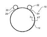
- FIG. 1shows a first embodiment of an opaque reinforcing ring according to the present invention
- FIG. 2shows a detail cross section along the line 2 - 2 ′ of the opaque reinforcing ring shown in FIG. 1 ;
- FIG. 3shows a stent graft incorporating reinforcing rings of the type shown in FIG. 1 ;
- FIG. 4shows an alternative embodiment of an opaque reinforcing ring according to the present invention.
- FIG. 5shows detail of a fenestration in a stent graft reinforced by a radiopaque reinforcing ring according to the present invention.
- FIG. 6shows reinforcing rings around the edge of the stent graft and around a scalloped fenestration.
- the opaque reinforcing ring 10comprises a plurality of turns of a composite twisted or braided wire 12 . Preferably there are about two turns of the wire although other numbers of turns may be used.
- the wire 12comprises a core 14 of a nickel titanium alloy, four peripheral strands 16 of a nickel titanium alloy and two strands 18 of a radiopaque wire such as gold, silver or platinum.
- the gold, silver or platinum wireprovides a radiopaque characteristic to the composite wire and the nickel titanium alloy gives shape memory characteristics to the composite wire.
- the wire 12can alternatively comprise, in an alternative embodiment, a core 14 of a nickel titanium alloy, two or three peripheral strands 16 of a nickel titanium alloy and three or four strands 18 of a radiopaque wire such as gold, silver and platinum.
- a radiopaque wiresuch as gold, silver and platinum.
- the total number of wires in the composite wirecan also vary.
- the wire 12is formed into a planar circular shape and the terminal ends 20 of the wire 12 are formed into loops 22 .
- the loopsform a small circle.
- the loops 22are provided to prevent the chance of damage to a lumen wall because the pointed ends of the composite wire are effectively enclosed within the respective loops.
- FIG. 3shows reinforcing rings according to the present invention used as a reinforcement for a fenestration of a stent graft.
- the stent graft 30comprises a tubular wall 32 .
- the tubular wallcan be a biocompatible graft material such as Dacron, ThoralonTM (a polyurethane material), expanded PTFE material or a naturally occurring biomaterial, such as an extracellular matrix, such as small intestinal submucosa or other suitable material.
- Gianturco style zig zag Z stents 34are provided inside the graft material of the tubular wall 32 at each end and between the ends Gianturco style zig zag Z stents 36 are provided on the outside of the graft material. There may be further Gianturco style zig zag Z stents on the tubular wall than those illustrated depending upon the overall length of the stent graft 30 .
- the tubular wall 32there is at least one substantially circular fenestration or aperture 40 on the tubular wall of the stent graft.
- there are two fenestrations 40being one for each of the two renal arteries when this embodiment is deployed into the aorta.
- Other numbers of fenestrationsmay also be used where the placement of the stent graft involves the possibility of occluding other branch vessels such as the superior mesenteric artery.
- the fenestrations 40are substantially circular.
- a ring 10 of the type shown in FIGS. 1 and 2is provided around the periphery of each fenestration 40 to give good dimensional stability to the fenestration 40 .
- Stitching 42is provided to retain the ring 10 around the periphery of the fenestration 40 .
- FIG. 3there is shown a scalloped fenestration 44 which opens to the end 35 of the stent graft.
- the scalloped fenestration 44may also be reinforced with a radiopaque shape memory wire of the present invention.
- This reinforcing memberis substantially U-shaped.
- the composite wire forming the reinforcement membermay be doubled back on itself to provide a reinforcement member with two strands of composite wire.
- FIG. 4shows an alternative embodiment of reinforcing ring according to the present invention.
- the opaque reinforcing ring 50 according to the present inventioncomprises a plurality of turns of a composite twisted wire 52 .
- the composite twisted wire 52comprises a core of a nickel titanium alloy, three peripheral strands of a nickel titanium alloy and three strands of a radiopaque wire such as gold, silver and platinum.
- the gold, silver and platinum wireprovides a radiopaque characteristic to the composite wire and the nickel titanium alloy gives shape memory characteristics to the composite wire.
- the wire 52is formed into a planar circular shape and the terminal ends 54 of the wire 52 are formed into loops 56 .
- the loops 56form a small circle and then a tail 58 .
- the loop 56is generally of a diameter through which can be passed a needle during stitching of the reinforcing ring into a graft material. Typically the loops may have a diameter of from 1 mm to 2 mm.
- the tail 58extends back around the periphery of the reinforcing ring. The loops 56 and tail 58 are provided to prevent the chance of damage to lumen wall in use.
- the tailsWhen stitched into a stent graft the tails are held in by the stitching which holds the ring at the periphery of a fenestration.
- the loops 56overlap each other.
- the ringWhen stitched around a fenestration with at least one stitch passing through both loops the ring withstand expansion forces within it during placement of a balloon expandable stent through it.
- the stitched loopshelp to resist circumferential or diametral expansion.
- the rings 10 and 50can have a diameter of from 4 to 15 mm when they are used as a reinforcing ring for a fenestration and from 10 to 40 mm when they are used as an end reinforcement for a tubular stent graft.
- the composite wirehas a diameter of 0.009 in. (0.23 mm)
- the nickel titanium alloy strandshave a diameter of 0.003 in. (0.076 mm)
- the platinum strandshave a diameter of 0.003 in. (0.076 mm).
- FIG. 5shows a detail of a reinforcing ring of the type shown in FIG. 1 stitched around a fenestration 40 .
- the ring 10is stitched by stitching 60 around a fenestration 40 in a graft material 32 .
- the loops 22lie flat onto the graft material and are stitched by stitches 60 a to the graft material.
Landscapes
- Health & Medical Sciences (AREA)
- Gastroenterology & Hepatology (AREA)
- Pulmonology (AREA)
- Cardiology (AREA)
- Oral & Maxillofacial Surgery (AREA)
- Transplantation (AREA)
- Engineering & Computer Science (AREA)
- Biomedical Technology (AREA)
- Heart & Thoracic Surgery (AREA)
- Vascular Medicine (AREA)
- Life Sciences & Earth Sciences (AREA)
- Animal Behavior & Ethology (AREA)
- General Health & Medical Sciences (AREA)
- Public Health (AREA)
- Veterinary Medicine (AREA)
- Prostheses (AREA)
- Media Introduction/Drainage Providing Device (AREA)
- Materials For Medical Uses (AREA)
Abstract
Description
Claims (10)
Priority Applications (1)
| Application Number | Priority Date | Filing Date | Title |
|---|---|---|---|
| US13/062,593US8579959B2 (en) | 2008-09-12 | 2009-09-11 | Radiopaque reinforcing member |
Applications Claiming Priority (3)
| Application Number | Priority Date | Filing Date | Title |
|---|---|---|---|
| US19188208P | 2008-09-12 | 2008-09-12 | |
| US13/062,593US8579959B2 (en) | 2008-09-12 | 2009-09-11 | Radiopaque reinforcing member |
| PCT/US2009/005096WO2010030370A1 (en) | 2008-09-12 | 2009-09-11 | Radiopaque reinforcing member |
Publications (2)
| Publication Number | Publication Date |
|---|---|
| US20110190868A1 US20110190868A1 (en) | 2011-08-04 |
| US8579959B2true US8579959B2 (en) | 2013-11-12 |
Family
ID=41260835
Family Applications (1)
| Application Number | Title | Priority Date | Filing Date |
|---|---|---|---|
| US13/062,593ActiveUS8579959B2 (en) | 2008-09-12 | 2009-09-11 | Radiopaque reinforcing member |
Country Status (5)
| Country | Link |
|---|---|
| US (1) | US8579959B2 (en) |
| EP (1) | EP2334258B1 (en) |
| JP (1) | JP2012501790A (en) |
| AU (1) | AU2009292193B2 (en) |
| WO (1) | WO2010030370A1 (en) |
Cited By (12)
| Publication number | Priority date | Publication date | Assignee | Title |
|---|---|---|---|---|
| US9956101B2 (en) | 2014-12-04 | 2018-05-01 | Trivascular, Inc. | Internal iliac preservation devices and methods |
| US10206796B2 (en) | 2014-08-27 | 2019-02-19 | DePuy Synthes Products, Inc. | Multi-strand implant with enhanced radiopacity |
| US10821008B2 (en) | 2016-08-25 | 2020-11-03 | DePuy Synthes Products, Inc. | Expansion ring for a braided stent |
| US10893963B2 (en) | 2018-08-06 | 2021-01-19 | DePuy Synthes Products, Inc. | Stent delivery with expansion assisting delivery wire |
| US11039944B2 (en) | 2018-12-27 | 2021-06-22 | DePuy Synthes Products, Inc. | Braided stent system with one or more expansion rings |
| US11090175B2 (en) | 2018-07-30 | 2021-08-17 | DePuy Synthes Products, Inc. | Systems and methods of manufacturing and using an expansion ring |
| US11129738B2 (en) | 2016-09-30 | 2021-09-28 | DePuy Synthes Products, Inc. | Self-expanding device delivery apparatus with dual function bump |
| US11357648B2 (en) | 2018-08-06 | 2022-06-14 | DePuy Synthes Products, Inc. | Systems and methods of using a braided implant |
| US11399929B2 (en) | 2017-02-24 | 2022-08-02 | Bolton Medical, Inc. | Vascular prosthesis with crimped adapter and methods of use |
| US11452623B2 (en) | 2013-03-13 | 2022-09-27 | DePuy Synthes Products, Inc. | Braided stent with expansion ring and method of delivery |
| US12144719B2 (en) | 2017-09-25 | 2024-11-19 | Bolton Medical, Inc. | Systems, devices, and methods for coupling a prosthetic implant to a fenestrated body |
| US12409052B2 (en) | 2016-06-13 | 2025-09-09 | Bolton Medical, Inc. | Systems, devices, and methods for marking and/or reinforcing fenestrations in prosthetic implants |
Families Citing this family (35)
| Publication number | Priority date | Publication date | Assignee | Title |
|---|---|---|---|---|
| US9034007B2 (en) | 2007-09-21 | 2015-05-19 | Insera Therapeutics, Inc. | Distal embolic protection devices with a variable thickness microguidewire and methods for their use |
| EP2189171A1 (en)* | 2008-11-25 | 2010-05-26 | Covidien AG | Mobile chest drainage unit, thoracic catheter, system comprising a mobile chest drainage unit and a thoracic catheter, and manufacturing method thereof |
| AU2009202301B8 (en)* | 2009-06-10 | 2009-12-03 | Cook Incorporated | Reinforcing ring |
| AU2010210022B1 (en)* | 2010-08-05 | 2011-09-08 | Cook Incorporated | Stent graft having a marker and a reinforcing and marker ring |
| GB2499377B (en) | 2012-02-01 | 2014-04-30 | Cook Medical Technologies Llc | Implantable medical device |
| US9737394B2 (en) | 2012-04-27 | 2017-08-22 | Medtronic Vascular, Inc. | Stent-graft prosthesis for placement in the abdominal aorta |
| US9393140B2 (en) | 2012-04-27 | 2016-07-19 | Medtronic Vascular, Inc. | Reconfigurable stent-graft delivery system and method of use |
| US8968384B2 (en) | 2012-04-27 | 2015-03-03 | Medtronic Vascular, Inc. | Circumferentially constraining sutures for a stent-graft |
| US9452069B2 (en) | 2012-04-27 | 2016-09-27 | Medtronic Vascular, Inc. | Reconfigurable stent-graft delivery system and method of use |
| US10098767B2 (en) | 2012-04-27 | 2018-10-16 | Medtronic Vascular, Inc. | Reconfigurable stent-graft delivery system and method of use |
| US9811613B2 (en) | 2012-05-01 | 2017-11-07 | University Of Washington Through Its Center For Commercialization | Fenestration template for endovascular repair of aortic aneurysms |
| CN105228688B (en) | 2013-03-15 | 2019-02-19 | 伊瑟拉医疗公司 | Vascular treatment devices and methods |
| US8715314B1 (en) | 2013-03-15 | 2014-05-06 | Insera Therapeutics, Inc. | Vascular treatment measurement methods |
| US8679150B1 (en) | 2013-03-15 | 2014-03-25 | Insera Therapeutics, Inc. | Shape-set textile structure based mechanical thrombectomy methods |
| US8690907B1 (en) | 2013-03-15 | 2014-04-08 | Insera Therapeutics, Inc. | Vascular treatment methods |
| US10105245B2 (en)* | 2013-08-23 | 2018-10-23 | Cook Medical Technologies Llc | Stent graft assembly for treating branched vessels |
| EP3294231A2 (en)* | 2015-05-08 | 2018-03-21 | Jayandiran Pillai | Stent and stent set |
| CN108697423A (en) | 2016-02-16 | 2018-10-23 | 伊瑟拉医疗公司 | The part flow arrangement of suction unit and anchoring |
| CN106236339B (en)* | 2016-07-22 | 2018-06-01 | 江苏大学 | A kind of conical blood vessel stent suitable for the main branch of bifurcated vessels |
| AU2017306141A1 (en) | 2016-08-02 | 2019-03-07 | Aortica Corporation | Systems, devices, and methods for coupling a prosthetic implant to a fenestrated body |
| CN108261254B (en)* | 2016-12-31 | 2024-05-28 | 先健科技(深圳)有限公司 | Bifurcated stent graft |
| ES2954897T3 (en) | 2017-02-24 | 2023-11-27 | Bolton Medical Inc | Constrained Wrap Stent Graft Delivery System |
| EP3932373B1 (en) | 2017-02-24 | 2022-12-21 | Bolton Medical, Inc. | Delivery system for radially constricting a stent graft |
| WO2018156849A1 (en) | 2017-02-24 | 2018-08-30 | Bolton Medical, Inc. | Vascular prosthesis with fenestration ring and methods of use |
| ES2863978T3 (en) | 2017-02-24 | 2021-10-13 | Bolton Medical Inc | System for radially constricting a stent graft |
| WO2018156854A1 (en) | 2017-02-24 | 2018-08-30 | Bolton Medical, Inc. | Radially adjustable stent graft delivery system |
| WO2018156850A1 (en) | 2017-02-24 | 2018-08-30 | Bolton Medical, Inc. | Stent graft with fenestration lock |
| EP3534837A1 (en) | 2017-02-24 | 2019-09-11 | Bolton Medical, Inc. | Constrainable stent graft, delivery system and methods of use |
| WO2018156847A1 (en) | 2017-02-24 | 2018-08-30 | Bolton Medical, Inc. | Delivery system and method to radially constrict a stent graft |
| WO2018156851A1 (en) | 2017-02-24 | 2018-08-30 | Bolton Medical, Inc. | Vascular prosthesis with moveable fenestration |
| CN110121319B (en) | 2017-10-31 | 2023-05-09 | 波顿医疗公司 | Distal torque component, delivery system, and method of use thereof |
| US20190192275A1 (en)* | 2017-12-22 | 2019-06-27 | Cook Medical Technologies Llc | Radiopaque markers on a medical device |
| FR3087113B1 (en) | 2018-10-12 | 2022-04-08 | Ludovic Canaud | STENT-TYPE AORTIC IMPLANT, AND SET OF TWO SUCH IMPLANTS |
| US11806225B2 (en)* | 2019-06-27 | 2023-11-07 | Lifetech Scientific (Shenzhen) Co. Ltd. | Covered stent |
| CN113116610B (en)* | 2019-12-30 | 2023-01-03 | 先健科技(深圳)有限公司 | Developing structure and blood vessel support |
Citations (13)
| Publication number | Priority date | Publication date | Assignee | Title |
|---|---|---|---|---|
| US4041931A (en)* | 1976-05-17 | 1977-08-16 | Elliott Donald P | Radiopaque anastomosis marker |
| WO1994013268A1 (en) | 1992-12-04 | 1994-06-23 | Kaplan Aaron V | Method and device for treating and enlarging body lumens |
| WO1997037616A2 (en) | 1996-04-05 | 1997-10-16 | Medtronic, Inc. | Endoluminal prostheses having position indicating markers |
| US6019736A (en)* | 1995-11-06 | 2000-02-01 | Francisco J. Avellanet | Guidewire for catheter |
| US20020091439A1 (en)* | 1994-12-15 | 2002-07-11 | Baker Steve G. | Graft assembly having support structure |
| US20030135971A1 (en)* | 1997-11-12 | 2003-07-24 | Michael Liberman | Bundle draw based processing of nanofibers and method of making |
| WO2005034808A1 (en) | 2003-10-10 | 2005-04-21 | William A. Cook Australia Pty. Ltd. | Fenestrated stent grafts |
| US20060004440A1 (en) | 1997-08-01 | 2006-01-05 | Stinson Jonathan S | Bioabsorbable marker having radiopaque constituents and method of using the same |
| WO2007095283A2 (en) | 2006-02-13 | 2007-08-23 | Willam A. Cook Australia Pty. Ltd. | Side branch stent graft construction |
| US7708771B2 (en)* | 2002-02-26 | 2010-05-04 | Endovascular Technologies, Inc. | Endovascular graft device and methods for attaching components thereof |
| US7862604B1 (en)* | 1995-02-24 | 2011-01-04 | Endovascular Technologies, Inc. | Bifurcated graft with an inferior extension |
| US20110295359A1 (en)* | 2004-05-14 | 2011-12-01 | Boston Scientific Scimed, Inc. | Stent With Reduced Weld Profiles and a Closed-End Wire Configuration |
| US20120150277A1 (en)* | 2008-06-16 | 2012-06-14 | Boston Scientific Scimed, Inc. | Continuous double layered stent for migration resistance |
Family Cites Families (1)
| Publication number | Priority date | Publication date | Assignee | Title |
|---|---|---|---|---|
| DE69507800T2 (en)* | 1994-05-19 | 1999-07-22 | Scimed Life Systems, Inc., Maple Grove, Minn. | IMPROVED TISSUE SUPPORTS |
- 2009
- 2009-09-11WOPCT/US2009/005096patent/WO2010030370A1/enactiveApplication Filing
- 2009-09-11AUAU2009292193Apatent/AU2009292193B2/enactiveActive
- 2009-09-11USUS13/062,593patent/US8579959B2/enactiveActive
- 2009-09-11JPJP2011526860Apatent/JP2012501790A/enactivePending
- 2009-09-11EPEP09789294Apatent/EP2334258B1/enactiveActive
Patent Citations (14)
| Publication number | Priority date | Publication date | Assignee | Title |
|---|---|---|---|---|
| US4041931A (en)* | 1976-05-17 | 1977-08-16 | Elliott Donald P | Radiopaque anastomosis marker |
| WO1994013268A1 (en) | 1992-12-04 | 1994-06-23 | Kaplan Aaron V | Method and device for treating and enlarging body lumens |
| US20020091439A1 (en)* | 1994-12-15 | 2002-07-11 | Baker Steve G. | Graft assembly having support structure |
| US7862604B1 (en)* | 1995-02-24 | 2011-01-04 | Endovascular Technologies, Inc. | Bifurcated graft with an inferior extension |
| US6019736A (en)* | 1995-11-06 | 2000-02-01 | Francisco J. Avellanet | Guidewire for catheter |
| WO1997037616A2 (en) | 1996-04-05 | 1997-10-16 | Medtronic, Inc. | Endoluminal prostheses having position indicating markers |
| US20060004440A1 (en) | 1997-08-01 | 2006-01-05 | Stinson Jonathan S | Bioabsorbable marker having radiopaque constituents and method of using the same |
| US20030135971A1 (en)* | 1997-11-12 | 2003-07-24 | Michael Liberman | Bundle draw based processing of nanofibers and method of making |
| US7708771B2 (en)* | 2002-02-26 | 2010-05-04 | Endovascular Technologies, Inc. | Endovascular graft device and methods for attaching components thereof |
| WO2005034808A1 (en) | 2003-10-10 | 2005-04-21 | William A. Cook Australia Pty. Ltd. | Fenestrated stent grafts |
| US7413573B2 (en)* | 2003-10-10 | 2008-08-19 | William A. Cook Australia Pty. Ltd. | Fenestrated stent grafts |
| US20110295359A1 (en)* | 2004-05-14 | 2011-12-01 | Boston Scientific Scimed, Inc. | Stent With Reduced Weld Profiles and a Closed-End Wire Configuration |
| WO2007095283A2 (en) | 2006-02-13 | 2007-08-23 | Willam A. Cook Australia Pty. Ltd. | Side branch stent graft construction |
| US20120150277A1 (en)* | 2008-06-16 | 2012-06-14 | Boston Scientific Scimed, Inc. | Continuous double layered stent for migration resistance |
Non-Patent Citations (1)
| Title |
|---|
| International Search Report and Written Opinion for PCT/US2009/005096 dated Nov. 25, 2009, 14 pgs. |
Cited By (19)
| Publication number | Priority date | Publication date | Assignee | Title |
|---|---|---|---|---|
| US11529249B2 (en) | 2013-03-13 | 2022-12-20 | DePuy Synthes Products, Inc. | Braided stent with expansion ring and method of delivery |
| US11452623B2 (en) | 2013-03-13 | 2022-09-27 | DePuy Synthes Products, Inc. | Braided stent with expansion ring and method of delivery |
| US10206796B2 (en) | 2014-08-27 | 2019-02-19 | DePuy Synthes Products, Inc. | Multi-strand implant with enhanced radiopacity |
| US10821010B2 (en) | 2014-08-27 | 2020-11-03 | DePuy Synthes Products, Inc. | Method of making a multi-strand implant with enhanced radiopacity |
| US11918498B2 (en) | 2014-12-04 | 2024-03-05 | Trivascular, Inc. | Internal iliac preservation devices and methods |
| US11033413B2 (en) | 2014-12-04 | 2021-06-15 | Trivascular, Inc. | Internal iliac preservation devices and methods |
| US9956101B2 (en) | 2014-12-04 | 2018-05-01 | Trivascular, Inc. | Internal iliac preservation devices and methods |
| US12409052B2 (en) | 2016-06-13 | 2025-09-09 | Bolton Medical, Inc. | Systems, devices, and methods for marking and/or reinforcing fenestrations in prosthetic implants |
| US10821008B2 (en) | 2016-08-25 | 2020-11-03 | DePuy Synthes Products, Inc. | Expansion ring for a braided stent |
| US12064363B2 (en) | 2016-09-30 | 2024-08-20 | DePuy Synthes Products, Inc. | Self-expanding device delivery apparatus with dual function bump |
| US11129738B2 (en) | 2016-09-30 | 2021-09-28 | DePuy Synthes Products, Inc. | Self-expanding device delivery apparatus with dual function bump |
| US11399929B2 (en) | 2017-02-24 | 2022-08-02 | Bolton Medical, Inc. | Vascular prosthesis with crimped adapter and methods of use |
| US12144719B2 (en) | 2017-09-25 | 2024-11-19 | Bolton Medical, Inc. | Systems, devices, and methods for coupling a prosthetic implant to a fenestrated body |
| US11497638B2 (en) | 2018-07-30 | 2022-11-15 | DePuy Synthes Products, Inc. | Systems and methods of manufacturing and using an expansion ring |
| US11090175B2 (en) | 2018-07-30 | 2021-08-17 | DePuy Synthes Products, Inc. | Systems and methods of manufacturing and using an expansion ring |
| US11357648B2 (en) | 2018-08-06 | 2022-06-14 | DePuy Synthes Products, Inc. | Systems and methods of using a braided implant |
| US12004977B2 (en) | 2018-08-06 | 2024-06-11 | DePuy Synthes Products, Inc. | Systems and methods of using a braided implant |
| US10893963B2 (en) | 2018-08-06 | 2021-01-19 | DePuy Synthes Products, Inc. | Stent delivery with expansion assisting delivery wire |
| US11039944B2 (en) | 2018-12-27 | 2021-06-22 | DePuy Synthes Products, Inc. | Braided stent system with one or more expansion rings |
Also Published As
| Publication number | Publication date |
|---|---|
| EP2334258B1 (en) | 2012-11-28 |
| AU2009292193A1 (en) | 2010-03-18 |
| EP2334258A1 (en) | 2011-06-22 |
| JP2012501790A (en) | 2012-01-26 |
| US20110190868A1 (en) | 2011-08-04 |
| WO2010030370A1 (en) | 2010-03-18 |
| AU2009292193B2 (en) | 2013-06-20 |
Similar Documents
| Publication | Publication Date | Title |
|---|---|---|
| US8579959B2 (en) | Radiopaque reinforcing member | |
| US10159560B2 (en) | Prosthesis having pivoting fenestration | |
| US10188503B2 (en) | Prosthesis having pivoting fenestration | |
| CA2806462C (en) | Stent graft having a marker and a reinforcing and marker ring | |
| US8702786B2 (en) | Prosthesis having pivoting fenestration | |
| US20090171442A1 (en) | Z-stent with incorporated barbs | |
| AU1730899A (en) | Wire reinforced vascular prosthesis | |
| US20240238110A1 (en) | Vascular Prosthesis With Drawn Filled Tubes | |
| US11759340B2 (en) | Optimised structure for an expandable implant of the stent or endoprosthesis type |
Legal Events
| Date | Code | Title | Description |
|---|---|---|---|
| AS | Assignment | Owner name:WILLIAM A. COOK AUSTRALIA PTY. LTD., AUSTRALIA Free format text:ASSIGNMENT OF ASSIGNORS INTEREST;ASSIGNORS:DUCKE, WERNER DIETER;HARTLEY, DAVID ERNEST;SIGNING DATES FROM 20090922 TO 20090923;REEL/FRAME:026081/0355 Owner name:COOK INCORPORATED, INDIANA Free format text:ASSIGNMENT OF ASSIGNORS INTEREST;ASSIGNORS:DUCKE, WERNER DIETER;HARTLEY, DAVID ERNEST;SIGNING DATES FROM 20090922 TO 20090923;REEL/FRAME:026081/0355 Owner name:COOK MEDICAL TECHNOLOGIES LLC, INDIANA Free format text:ASSIGNMENT OF ASSIGNORS INTEREST;ASSIGNOR:COOK INCORPORATED;REEL/FRAME:026081/0416 Effective date:20110317 | |
| AS | Assignment | Owner name:COOK MEDICAL TECHNOLOGIES LLC, INDIANA Free format text:ASSIGNMENT OF ASSIGNORS INTEREST;ASSIGNOR:WILLIAM A. COOK AUSTRALIA PTY. LTD.;REEL/FRAME:031354/0174 Effective date:20131001 | |
| STCF | Information on status: patent grant | Free format text:PATENTED CASE | |
| FPAY | Fee payment | Year of fee payment:4 | |
| MAFP | Maintenance fee payment | Free format text:PAYMENT OF MAINTENANCE FEE, 8TH YEAR, LARGE ENTITY (ORIGINAL EVENT CODE: M1552); ENTITY STATUS OF PATENT OWNER: LARGE ENTITY Year of fee payment:8 | |
| AS | Assignment | Owner name:WILMINGTON TRUST, NATIONAL ASSOCIATION, AS COLLATERAL AGENT, DELAWARE Free format text:SECURITY INTEREST;ASSIGNOR:COOK MEDICAL TECHNOLOGIES LLC;REEL/FRAME:066700/0277 Effective date:20240227 | |
| MAFP | Maintenance fee payment | Free format text:PAYMENT OF MAINTENANCE FEE, 12TH YEAR, LARGE ENTITY (ORIGINAL EVENT CODE: M1553); ENTITY STATUS OF PATENT OWNER: LARGE ENTITY Year of fee payment:12 |