US8579913B2 - Drive assembly for facilitating deployment of an implantable medical device - Google Patents
Drive assembly for facilitating deployment of an implantable medical deviceDownload PDFInfo
- Publication number
- US8579913B2 US8579913B2US13/369,911US201213369911AUS8579913B2US 8579913 B2US8579913 B2US 8579913B2US 201213369911 AUS201213369911 AUS 201213369911AUS 8579913 B2US8579913 B2US 8579913B2
- Authority
- US
- United States
- Prior art keywords
- sheath
- yoke
- brake
- assembly
- handle
- Prior art date
- Legal status (The legal status is an assumption and is not a legal conclusion. Google has not performed a legal analysis and makes no representation as to the accuracy of the status listed.)
- Active
Links
Images


Classifications
- A—HUMAN NECESSITIES
- A61—MEDICAL OR VETERINARY SCIENCE; HYGIENE
- A61F—FILTERS IMPLANTABLE INTO BLOOD VESSELS; PROSTHESES; DEVICES PROVIDING PATENCY TO, OR PREVENTING COLLAPSING OF, TUBULAR STRUCTURES OF THE BODY, e.g. STENTS; ORTHOPAEDIC, NURSING OR CONTRACEPTIVE DEVICES; FOMENTATION; TREATMENT OR PROTECTION OF EYES OR EARS; BANDAGES, DRESSINGS OR ABSORBENT PADS; FIRST-AID KITS
- A61F2/00—Filters implantable into blood vessels; Prostheses, i.e. artificial substitutes or replacements for parts of the body; Appliances for connecting them with the body; Devices providing patency to, or preventing collapsing of, tubular structures of the body, e.g. stents
- A61F2/95—Instruments specially adapted for placement or removal of stents or stent-grafts
- A61F2/9517—Instruments specially adapted for placement or removal of stents or stent-grafts handle assemblies therefor
- A—HUMAN NECESSITIES
- A61—MEDICAL OR VETERINARY SCIENCE; HYGIENE
- A61F—FILTERS IMPLANTABLE INTO BLOOD VESSELS; PROSTHESES; DEVICES PROVIDING PATENCY TO, OR PREVENTING COLLAPSING OF, TUBULAR STRUCTURES OF THE BODY, e.g. STENTS; ORTHOPAEDIC, NURSING OR CONTRACEPTIVE DEVICES; FOMENTATION; TREATMENT OR PROTECTION OF EYES OR EARS; BANDAGES, DRESSINGS OR ABSORBENT PADS; FIRST-AID KITS
- A61F2/00—Filters implantable into blood vessels; Prostheses, i.e. artificial substitutes or replacements for parts of the body; Appliances for connecting them with the body; Devices providing patency to, or preventing collapsing of, tubular structures of the body, e.g. stents
- A61F2/95—Instruments specially adapted for placement or removal of stents or stent-grafts
- A61F2/962—Instruments specially adapted for placement or removal of stents or stent-grafts having an outer sleeve
- A61F2/966—Instruments specially adapted for placement or removal of stents or stent-grafts having an outer sleeve with relative longitudinal movement between outer sleeve and prosthesis, e.g. using a push rod
- A—HUMAN NECESSITIES
- A61—MEDICAL OR VETERINARY SCIENCE; HYGIENE
- A61F—FILTERS IMPLANTABLE INTO BLOOD VESSELS; PROSTHESES; DEVICES PROVIDING PATENCY TO, OR PREVENTING COLLAPSING OF, TUBULAR STRUCTURES OF THE BODY, e.g. STENTS; ORTHOPAEDIC, NURSING OR CONTRACEPTIVE DEVICES; FOMENTATION; TREATMENT OR PROTECTION OF EYES OR EARS; BANDAGES, DRESSINGS OR ABSORBENT PADS; FIRST-AID KITS
- A61F2250/00—Special features of prostheses classified in groups A61F2/00 - A61F2/26 or A61F2/82 or A61F9/00 or A61F11/00 or subgroups thereof
- A61F2250/0058—Additional features; Implant or prostheses properties not otherwise provided for
- A61F2250/0073—Force-limiting means
Definitions
- the present inventionrelates to a drive assembly for facilitating deployment of an implantable medical device.
- Implantable medical devicessuch as stents, stent grafts, vena cava filters, occlusion devices, embolisation coils and so on, are often deployed endoluminally through a suitable percutaneous entry point of a patient.
- a medical device to be fitted within the aortamay be passed via the femoral artery, thus from an entry point a substantial distance from the treatment site.
- the introducers used for the deployment of such devicestend to be elongate catheter assemblies in which the medical device is held at a distal end of the introducer in a radially compressed state until it is ready to be deployed.
- such introducer assembliesare formed from a plurality of components including one or more catheters, device restraining elements, guide wires and so on.
- the introduceralso includes a covering sheath which covers the components of the introducer as well as the medical device.
- the deployment mechanismis operated.
- the first stage of thisis to pull back the outer sheath so as to expose the medical device, whereupon the constraining mechanism holding the medical device to the carrier catheter is then activated, normally in stages, to release the device.
- the deviceis releasable by self-expansion while in other cases a separate expansion mechanism, such as a balloon, is used.
- the components of the assemblytend to be a relatively tight fit with one another. This relatively tight fit results in friction between the various slidable components of the assembly.
- the proximal end of the devicethat is the end which remains outside the patient during the procedure and which includes the various manual controls used by the clinician, is provided with at least one haemostatic valve or seal, often several, to prevent undesired loss of bodily fluids during the operation.
- a seal or valvebetween the covering sheath and the inner catheter or catheters to prevent fluid leakage from the space between these components. Such seals tend to contribute to friction between the various sliding components of the device and thus to an increased required operation force.
- introducer devices of this naturetend to be very long, an introducer for a medical device to be implanted in the aorta or heart typically having a length of at least 1.5 metres.
- the path such introducers have to follow through a patient's vasculatureis normally tortuous, such that they have to curve and often twist along their length. Such curvature and twisting also adds to the friction between the slidable components of the assembly.
- the clinicianmay need to carry out positional adjustments to the assembly at the same time as effecting the various steps required to deploy the device, which is a complex and time consuming task.
- the devicecannot be properly deployed and the procedure must be aborted.
- cliniciansdo not wish to lose the manual control of the operation of the introducer assembly as this can lead to a loss of the fine adjustments clinicians often desire during deployment of the medical device. For instance, a clinician may wish to slow or even temporarily stop the withdrawal of the sheath part way in order to carry out a fine adjustment of the position or orientation of the medical prosthesis.
- An automatic deployment devicemay not provide for this.
- a manually operated introducergives the clinician tactile feedback as to how the deployment is progressing, whereas an automatic deployment mechanism will generally fail to provide such feedback, causing the clinician to have to rely upon imaging only.
- the present inventionseeks to provide an improved introducer assembly and drive assembly for an introducer.
- an introducer assemblyincluding a carrier element for carrying an implantable medical device, the carrier element including a distal end at which an implantable medical device is carried and a proximal end; a sheath overlying the carrier element and being retractable so as to expose the distal end of the carrier element, the sheath including a distal end and a proximal end; a handle assembly at the proximal end of the carrier element and sheath, the handle assembly being manually operable to retract the sheath; and a drive assembly coupled between the carrier element and the sheath and operable to provide a retraction assistance force upon manual retraction of the sheath.
- An introducer having such a structureretains the manual operation and tactile feel not provided with automatic actuator systems, yet provides mechanical assistance in order to avoid the problems of existing manually operable introducer assemblies.
- the handle assemblyincludes first and second handle portions, attached respectively to the proximal ends of the sheath and the carrier element.
- the two handle portionscan be held by a clinician and pulled in a direction towards one another so as to retract the sheath from the distal end of the carrier element and thereby to expose a medical device carried thereon.
- the drive meansis coupled between the first and second handle portions and acts to provide a force pulling these handle portions together.
- the sprung elementis coupled between the handle portions.
- the drive assemblypreferably includes a sprung element coupled to the sheath and operable to pull the sheath in a retraction direction.
- the sprung elementmay in some embodiments provide a retraction force which is insufficient to pull back the sheath without manual assistance. In other embodiments, as described below, the sprung element may generate a force sufficient to pull back the sheath, in which case there would be provided a control mechanism to ensure retraction of the sheath only when desired.
- the drive assemblyincludes a brake element operable to prevent retraction of the sheath until the sheath is manually pulled back by the user.
- the brake elementadopts a braking condition when there is no manual actuation of the handle assembly and a released condition when there is manual operation of the handle assembly.
- the brakeacts to prevent operation of the sprung element.
- the drive assemblyprovides mechanical assistance up to a threshold retraction rate, beyond which the only effective retraction force is from manual actuation of the handle assembly.
- thisis by means of the drive assembly having a sprung element which has a limited return speed, that is a limited speed by which it returns to its not stressed condition. This may be achieved by an inherent dynamic limitation in the sprung element or by means of a damper, for instance.
- the sprung elementis preferably a spiral spring, preferably of a type similar to a watch or clock spring.
- a springcan be fitted to a spool element and the brake means can be designed to act upon the spool element so as to stop this from rotating and thereby to stop the spring from moving the handle portions towards one another.
- the brake elementcan be releasable upon manual movement of the handle portions.
- the drive assemblypreferably includes a brake release mechanism operable to release the brake upon manual pulling of the handle portions together.
- the brake release mechanismmay operate on the basis of the speed of manual retraction, thereby providing controlled force assistance. If manual retraction is too slow the brake engages again, thereby ensuring that the clinician never loses control of the operation of the introducer.
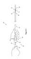
- FIG. 1shows an example of the proximal end of a prior art introducer assembly
- FIG. 2shows in schematic form the primary components of a preferred embodiment of introducer assembly incorporating a drive assembly
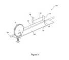
- FIG. 3shows detail of the drive assembly of FIG. 2 ;
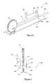
- FIG. 4shows in schematic form an embodiment of brake mechanism for the assembly of FIG. 3 ;
- FIGS. 5 and 6show in detail a preferred embodiment of drive assembly which includes a speed control function
- FIGS. 7 to 9show the drive assembly of FIGS. 5 and 6 in three different modes of operation.
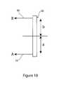
- FIG. 10shows in schematic form a force ratio balancing scheme for the yoke 56 .
- distalis used to refer to an end of a component which in use is furthest from the surgeon during the medical procedure, including within a patient.
- proximalis used to refer to an end of a component closest to the surgeon and in practice in or adjacent an external manipulation part of the deployment or treatment apparatus.
- FIG. 1there is shown an introducer assembly 10 designed for deploying implantable medical devices within the lumen of a patient.
- the assembly 10of which only the principal components are shown, has a proximal end 12 which remains outside the patient during the medical procedure and a distal end 14 which during the procedure is located within a patient's vasculature or other organ.
- the distal end 14carries, in this example, an implantable medical device 16 , as shown in FIG. 2 .
- the introducer assembly 10includes a carrier element or catheter 18 which has a proximal end 20 at the proximal end 12 of the assembly and a distal end 22 at the distal end 14 of the assembly 10 .
- the carrier element 18carries, at its distal end, an implantable medical device 16 and is typically provided with restraining mechanisms for holding the medical device 16 in a radially constrained configuration, as well as one or more lumens for guide wires, flushing fluid and so on.
- the structure of the carrier element 18can be of a type well known in the art and therefore is not described in detail herein.
- a sheath 24Located over the carrier element 18 is a sheath 24 , which has a proximal end 26 and a distal end 28 which extends up to the distal end 14 of the introducer 10 .
- the distal end 28 of the sheath 24covers all or most of the distal end of the carrier element 18 and in particular covers the medical device 16 , as will be apparent from a comparison of FIGS. 1 and 2 .
- first and second handle units 30 , 32The proximal ends 26 , 20 of the sheath 24 and carrier catheter 18 are attached, respectively, to first and second handle units 30 , 32 .
- the handle units 30 , 32include haemostatic valves, flushing ports, possibly one or more device release mechanisms and so on. As such features are well known in the art they are not described in detail herein.
- FIG. 2The conventional manner of operating the introducer assembly of FIG. 1 can be seen with reference to FIG. 2 .
- the clinicianholds the two handle portions 30 , 32 with two hands and pulls back the sheath by pulling back the handle 30 relative to the handle unit 32 , in the direction of the arrow 34 .
- This actioncauses the distal end 28 of the sheath 24 to be retracted relative to the distal end 22 of the carrier catheter 18 , so as to expose the medical device 16 .
- this operationis carried out once the introducer assembly 10 has been satisfactorily positioned within a patient, such that the distal end 14 of the introducer assembly 10 is located at the site at which the implantable medical device 16 is to be deployed. Up to that point, the distal end 28 of the sheath 24 is retained in its covering position, that is to overlie the medical device 16 .
- FIG. 3there is shown a preferred embodiment of drive assembly 50 , coupled between the carrier element 18 and the sheath 24 .
- the drive assembly 50is designed to provide retraction assistance force upon manual retraction of the sheath.
- the drive assembly 50is, in this embodiment, coupled to the handle portions 30 , 32 of the sheath 24 and carrier element or catheter 18 , respectively.
- the retraction force of the drive assembly 50is provided, in this embodiment, by means of a spiral spring 52 , which is supported on a reel or spool, of which an embodiment is shown in FIG. 4 and described below.
- the spring element 52is attached at one end 54 to a yoke 56 which is fitted over the sheath 24 just distal of the handle unit 30 .
- the yoke 56includes a hole or bore therein (not shown) through which the sheath 24 can pass.
- the support for the sprung element 52(of which an embodiment is shown in FIG. 4 ) is connected to the handle unit 32 in such a manner that a clinician can still hold in one hand the handle unit 32 (or any other component which is directly connected to the handle unit 32 ).
- a gripping element 58which, in this embodiment, is attached to the yoke 56 by means of a tether 60 .
- the yoke 56acts upon the handle unit 30 through a coil spring 62 , which is held at one end by the yoke 56 and at its other end against the handle unit 30 (for this purpose, there may be provided a suitable stop element, for example a washer between the handle unit 30 and the end of the coil spring 62 ).
- a brake release element 64which, as described below, acts with the yoke, the gripper 58 and sprung element 52 .
- a brake element 66Adjacent the brake release element 64 is a brake element 66 , which has a proximal end 68 able to engage the mechanism of the sprung element 52 so as to stop this from imparting a pulling force on the yoke 56 , thereby on the handle unit 30 , in a manner described in detail below.
- the brake element 66is pivotable about a pivot point 70 .
- the pivot point 70preferably allows the brake element 66 to tilt sideways relative to its longitudinal axis, as described in further detail below.
- the yoke 56is able to tilt to a certain extent on the sheath 24 , in dependence upon the magnitude of the forces applied to it by the sprung element 52 and by the grip element 58 (that is by the clinician).
- FIG. 4there is shown in schematic form an example of brake mechanism for the assembly shown in FIG. 3 .
- the spiral spring 52is fitted to a toothed spool 76 , with the coiled end of the spring 52 fixed into a suitable support (not shown) of the spool 76 .
- the brake element 66is provided at its end 68 with a toothed region 78 able to engage the teeth of the spool 76 .
- the brake element 66when the brake element 66 is biased towards the spool 26 its teeth will engage the teeth at the spool element 76 so as to stop this from rotating, thereby to stop the sprung element 52 imparting any further pulling force on the yoke 56 and thus upon the handle unit 30 .
- the assembly 50 shown in FIG. 3(as with the mechanism shown in FIGS. 4 and 5 to 9 described in further detail below) will be provided on a frame or housing to support the various components.
- Such frame or housingwill be dependent upon the design of the final form of the assembly 50 , as well as dependent upon user preference.
- the design of such a housing or support frameis well within the capabilities of the skilled person and it is therefore not considered necessary to describe a particular housing in order to illustrate the principles of the invention taught herein.
- a weak springwhich tends to bias the brake element 66 into a released position (that is to be biased to rotate in an anti-clockwise direction in the view of FIG. 3 ), in order to facilitate the release of the driver means and in particular the function of the sprung element 52 .
- the spring 62 upon which the yoke 56 is mountedenables the sprung element 52 to impart a tilting force upon the yoke 56 to cause this to engage the brake element 66 but not a force which is sufficient to overcome the spring 62 and thereby to move the handle unit 30 towards the handle unit 32 .
- the yoke 56will remain in the tilted position, with the release element 64 pressing against the brake element 66 , until manual actuation of the drive element of the assembly 50 .
- the pulling force provided by the sprung element 52assists in the retraction of a sheath 24 , thereby to provide mechanical assistance to the effort expended by the clinician in pulling the handle 58 .
- the spring 52acts to provide an additional retraction force, thereby reducing the amount of effort which the clinician needs to apply to the introducer assembly 10 .
- This assistancereduces the risk of the clinician jolting or otherwise undesirably moving the introducer assembly 10 during the deployment procedure and thereby reduces the risk of the distal end 14 of the assembly 10 being moved so as to become displaced in the patient's vasculature.
- the spring 52will provide a greater pulling force compared to the force it will produce towards the end of its rotational travel. This greater initial force is useful in overcoming the greater frictional forces experienced at the start of pulling back of the sheath 24 .
- the sprung element 52will pull at a greater speed, thereby tilting the yoke 56 in the direction of the arrow 74 , to cause the release element 64 to re-engage the brake element 66 and stop further assistance by the sprung element 52 . Therefore, the assistance provided by the sprung element 52 will only occur while the clinician is pulling the gripper element 58 at at least the same speed as the speed of retraction provided by the sprung element 52 . This provides retraction control. As described below, the soft braking function of the brake element 66 and pad 114 can provide advantageous speed control for the physician.
- This combination of effectsprovides a control to the amount and nature of the mechanical assistance (the force assistance) which is generated by the assembly 50 .
- the clinicianremains in complete control of the deployment operation, including factors such as speed of retraction of the sheath 24 , in a manner which is not possible with some fully automated systems. Specifically, should the clinician pull the gripper element 58 too slowly, the brake will continue to be engaged in a repetitive manner, whereas if the clinician pulls at a median rate there is full force assistance from the sprung element 52 , while if the clinician pulls at a faster rate than the operating rate of the spring 52 , there will be no force assistance.
- the arrangement and operation of the drive assembly 50could be described as to provide servo assistance to the introducer 10 .
- FIGS. 5 and 6there is shown an embodiment of brake mechanism which includes a speed control function in addition to a brake function.
- the assembly 100 of this embodimentmakes use of the yoke 56 previously described and toothed wheel 76 supporting the spiral spring 52 .
- the additional featuresrelate to the brake and speed control assembly 102 .
- the assemblyincludes a pivotable and twistable control rod 104 to which is attached an elongate flange or wing 106 . Resting on and slidable along the flange 106 is a contact arm 108 which is coupled to the yoke 56 , in practice to rotate the rod 104 .
- Brake pad 114may be a friction element of conventional form, one example being rubber or a rubberlike material.
- a spring 116is provided at what could be termed with respect to the drawings on the underside of the flange 106 and is held by a suitable support 118 , which would typically be part of the casing or frame of the assembly.
- the spring 116biases the flange 106 towards the toothed wheel 76 , in practice in a braking and locking configuration.
- Spring 116is of a strength that it is sufficient to cause braking of the mechanism when no external forces are applied thereto but which is overcome when the handle 58 is pulled in the normal course of deployment, as described herein.
- the mechanism 100is shown in three different operating conditions.
- FIG. 7there is no external force applied to the mechanism 102 by the yoke 56 ; that is, the handle 58 is not being operated by the clinician and the spring 116 is therefore able to cause the speed control brake pad 114 to engage the toothed wheel 76 as well as the toothed ratchet 178 at the end of the flange 106 .
- FIG. 8shows a condition in which the yoke 56 is only partially tilted, as a result of pulling of the handle 58 at only an intermediate rate, which is sufficient to rotate the rod 104 and therefore the flange 106 enough to disengage the teeth 178 from the toothed wheel 76 which still results in application of the brake pad 114 against the side of the toothed wheel 76 .
- Thiscontrols the speed of rotation of the toothed wheel 76 and therefore the speed of retraction of the sheath 24 .
- the force of the brake pad 114 against the toothed wheel 76can be adjusted by increasing or reducing the speed of pulling on the handle 58 within this intermediate range, thereby to control the speed of rotation of the toothed wheel 76 thereby the speed of retraction of the sheath 24 .
- Abutment of the brake pad 114 against the side of the spool 76generates a frictional braking force able to impart a gradual braking of the spool 76 and thus of the spring assistance on the assembly.
- Thiscan give the brake 66 a soft braking function to slow the handle gradually.
- Thiscan also provide an element of speed control in a manner similar to using a car's brake to control the speed of the car.
- brake mechanism 66provides both braking by the brake pad 114 and by engagement of the teeth 78 .
- Linear force B(applied by the handle 58 ) is determined in terms of its moment of force by the distance b relative to the pivot point of the yoke 56 .
- force A provided by the spring 52is determined by the distance a to the pivot point of the yoke 56 .
- manual force B ⁇ length bis balanced over the yoke pivot point with respect to servo force A ⁇ distance a .
- the required pulling forcecan be adjust by adjusting the ratio of a to b , that is by adjusting the relative distances between the points of pulling of 60 or 52 on the pivot point of the yoke 56 .
- Such adjustmentcan be provided in a manner which can be effected by the clinician or factory set as preferred.
- the drive assembly disclosed hereincan be used with existing designs of manually operated introducer assemblies, for instance for the applicant's Zenith endovascular graft.
- the drive assemblycould, therefore, be provided also as a device which can be fitted as a retrofit item to a conventional manually operated introducer assembly.
Landscapes
- Health & Medical Sciences (AREA)
- Engineering & Computer Science (AREA)
- Biomedical Technology (AREA)
- Life Sciences & Earth Sciences (AREA)
- Oral & Maxillofacial Surgery (AREA)
- Transplantation (AREA)
- Heart & Thoracic Surgery (AREA)
- Vascular Medicine (AREA)
- Cardiology (AREA)
- Animal Behavior & Ethology (AREA)
- General Health & Medical Sciences (AREA)
- Public Health (AREA)
- Veterinary Medicine (AREA)
- Prostheses (AREA)
- Surgical Instruments (AREA)
- Media Introduction/Drainage Providing Device (AREA)
Abstract
Description
Claims (20)
Applications Claiming Priority (2)
| Application Number | Priority Date | Filing Date | Title |
|---|---|---|---|
| GB1102460.1AGB2488107B (en) | 2011-02-11 | 2011-02-11 | Drive assembly for facilitating deployment of an implantable medical device |
| GB1102460.1 | 2011-02-11 |
Publications (2)
| Publication Number | Publication Date |
|---|---|
| US20120209175A1 US20120209175A1 (en) | 2012-08-16 |
| US8579913B2true US8579913B2 (en) | 2013-11-12 |
Family
ID=43859308
Family Applications (1)
| Application Number | Title | Priority Date | Filing Date |
|---|---|---|---|
| US13/369,911ActiveUS8579913B2 (en) | 2011-02-11 | 2012-02-09 | Drive assembly for facilitating deployment of an implantable medical device |
Country Status (3)
| Country | Link |
|---|---|
| US (1) | US8579913B2 (en) |
| EP (1) | EP2486896B1 (en) |
| GB (1) | GB2488107B (en) |
Cited By (35)
| Publication number | Priority date | Publication date | Assignee | Title |
|---|---|---|---|---|
| US20150119978A1 (en)* | 2013-10-29 | 2015-04-30 | Tendyne Holdings, Inc. | Apparatus and methods for delivery of transcatheter prosthetic valves |
| US9730792B2 (en) | 2007-09-13 | 2017-08-15 | Georg Lutter | Truncated cone heart valve stent |
| US9833315B2 (en) | 2011-08-11 | 2017-12-05 | Tendyne Holdings, Inc. | Prosthetic valves and related inventions |
| US9895221B2 (en) | 2012-07-28 | 2018-02-20 | Tendyne Holdings, Inc. | Multi-component designs for heart valve retrieval device, sealing structures and stent assembly |
| US9986993B2 (en) | 2014-02-11 | 2018-06-05 | Tendyne Holdings, Inc. | Adjustable tether and epicardial pad system for prosthetic heart valve |
| US10201419B2 (en) | 2014-02-05 | 2019-02-12 | Tendyne Holdings, Inc. | Apparatus and methods for transfemoral delivery of prosthetic mitral valve |
| US10219900B2 (en) | 2012-07-30 | 2019-03-05 | Tendyne Holdings, Inc. | Delivery systems and methods for transcatheter prosthetic valves |
| US10327894B2 (en) | 2015-09-18 | 2019-06-25 | Tendyne Holdings, Inc. | Methods for delivery of prosthetic mitral valves |
| US10405976B2 (en) | 2013-05-30 | 2019-09-10 | Tendyne Holdings, Inc. | Structural members for prosthetic mitral valves |
| US10463494B2 (en) | 2013-04-02 | 2019-11-05 | Tendyne Holdings, Inc. | Prosthetic heart valve and systems and methods for delivering the same |
| US10463489B2 (en) | 2013-04-02 | 2019-11-05 | Tendyne Holdings, Inc. | Prosthetic heart valve and systems and methods for delivering the same |
| US10470877B2 (en) | 2016-05-03 | 2019-11-12 | Tendyne Holdings, Inc. | Apparatus and methods for anterior valve leaflet management |
| US10478293B2 (en) | 2013-04-04 | 2019-11-19 | Tendyne Holdings, Inc. | Retrieval and repositioning system for prosthetic heart valve |
| US10517728B2 (en) | 2014-03-10 | 2019-12-31 | Tendyne Holdings, Inc. | Devices and methods for positioning and monitoring tether load for prosthetic mitral valve |
| US10555718B2 (en) | 2013-10-17 | 2020-02-11 | Tendyne Holdings, Inc. | Apparatus and methods for alignment and deployment of intracardiac devices |
| US10595996B2 (en) | 2013-06-25 | 2020-03-24 | Tendyne Holdings, Inc. | Thrombus management and structural compliance features for prosthetic heart valves |
| US10610354B2 (en) | 2013-08-01 | 2020-04-07 | Tendyne Holdings, Inc. | Epicardial anchor devices and methods |
| US10610356B2 (en) | 2015-02-05 | 2020-04-07 | Tendyne Holdings, Inc. | Expandable epicardial pads and devices and methods for delivery of same |
| US10610358B2 (en) | 2015-12-28 | 2020-04-07 | Tendyne Holdings, Inc. | Atrial pocket closures for prosthetic heart valves |
| US10667905B2 (en) | 2015-04-16 | 2020-06-02 | Tendyne Holdings, Inc. | Apparatus and methods for delivery, repositioning, and retrieval of transcatheter prosthetic valves |
| US10786351B2 (en) | 2015-01-07 | 2020-09-29 | Tendyne Holdings, Inc. | Prosthetic mitral valves and apparatus and methods for delivery of same |
| US10952844B2 (en) | 2011-12-16 | 2021-03-23 | Tendyne Holdings, Inc. | Tethers for prosthetic mitral valve |
| US11039921B2 (en) | 2016-06-13 | 2021-06-22 | Tendyne Holdings, Inc. | Sequential delivery of two-part prosthetic mitral valve |
| US11065116B2 (en) | 2016-07-12 | 2021-07-20 | Tendyne Holdings, Inc. | Apparatus and methods for trans-septal retrieval of prosthetic heart valves |
| US11090157B2 (en) | 2016-06-30 | 2021-08-17 | Tendyne Holdings, Inc. | Prosthetic heart valves and apparatus and methods for delivery of same |
| US11096782B2 (en) | 2015-12-03 | 2021-08-24 | Tendyne Holdings, Inc. | Frame features for prosthetic mitral valves |
| US11154399B2 (en) | 2017-07-13 | 2021-10-26 | Tendyne Holdings, Inc. | Prosthetic heart valves and apparatus and methods for delivery of same |
| US11179236B2 (en) | 2009-12-08 | 2021-11-23 | Colorado State University Research Foundation | Device and system for transcatheter mitral valve replacement |
| US11191639B2 (en) | 2017-08-28 | 2021-12-07 | Tendyne Holdings, Inc. | Prosthetic heart valves with tether coupling features |
| US11224510B2 (en) | 2013-04-02 | 2022-01-18 | Tendyne Holdings, Inc. | Prosthetic heart valve and systems and methods for delivering the same |
| US11648114B2 (en) | 2019-12-20 | 2023-05-16 | Tendyne Holdings, Inc. | Distally loaded sheath and loading funnel |
| US11648110B2 (en) | 2019-12-05 | 2023-05-16 | Tendyne Holdings, Inc. | Braided anchor for mitral valve |
| US11678980B2 (en) | 2020-08-19 | 2023-06-20 | Tendyne Holdings, Inc. | Fully-transseptal apical pad with pulley for tensioning |
| US11951002B2 (en) | 2020-03-30 | 2024-04-09 | Tendyne Holdings, Inc. | Apparatus and methods for valve and tether fixation |
| US12048818B2 (en) | 2020-07-05 | 2024-07-30 | New Wave Endo-Surgical Corp. | Handheld elongate medical device advancer and related systems, devices and methods |
Families Citing this family (3)
| Publication number | Priority date | Publication date | Assignee | Title |
|---|---|---|---|---|
| US10441449B1 (en) | 2018-05-30 | 2019-10-15 | Vesper Medical, Inc. | Rotary handle stent delivery system and method |
| US10449073B1 (en) | 2018-09-18 | 2019-10-22 | Vesper Medical, Inc. | Rotary handle stent delivery system and method |
| US11219541B2 (en) | 2020-05-21 | 2022-01-11 | Vesper Medical, Inc. | Wheel lock for thumbwheel actuated device |
Citations (7)
| Publication number | Priority date | Publication date | Assignee | Title |
|---|---|---|---|---|
| US20030028236A1 (en) | 2001-07-31 | 2003-02-06 | Gillick Matthew J. | Control device and mechanism for deploying a self-expanding medical device |
| US20050090887A1 (en) | 2003-10-22 | 2005-04-28 | Pryor Jack D. | Delivery system for long self-expanding stents |
| WO2005107644A1 (en) | 2004-04-27 | 2005-11-17 | Boston Scientific Limited | Stent delivery system |
| US20090024137A1 (en)* | 2007-07-16 | 2009-01-22 | Cook Incorporated | Prosthesis Delivery and Deployment Device |
| WO2009013642A1 (en) | 2007-07-25 | 2009-01-29 | Abbott Laboratories Vascular Enterprises Limited | System for controlled prosthesis deployment |
| US20090270969A1 (en)* | 2008-04-26 | 2009-10-29 | Biotronik Vi Patent Ag | Delivery system having a release mechanism for releasing an object carried by a catheter as well as a release mechanism of a delivery system |
| US20120029607A1 (en)* | 2010-07-30 | 2012-02-02 | Mchugo Vincent | Controlled release and recapture prosthetic deployment device |
Family Cites Families (3)
| Publication number | Priority date | Publication date | Assignee | Title |
|---|---|---|---|---|
| FR1505334A (en) | 1965-12-02 | 1967-12-15 | Rhone Poulenc Sa | New ruthenium complexes |
| US20090138023A1 (en)* | 2005-12-13 | 2009-05-28 | Johnson Kirk L | Actuator Handle for Use With Medical Device Deployment Systems |
| EP2328524B1 (en)* | 2008-07-02 | 2019-01-16 | Cook Medical Technologies LLC | Deployment assembly |
- 2011
- 2011-02-11GBGB1102460.1Apatent/GB2488107B/enactiveActive
- 2012
- 2012-02-09USUS13/369,911patent/US8579913B2/enactiveActive
- 2012-02-10EPEP12154962.0Apatent/EP2486896B1/enactiveActive
Patent Citations (8)
| Publication number | Priority date | Publication date | Assignee | Title |
|---|---|---|---|---|
| US20030028236A1 (en) | 2001-07-31 | 2003-02-06 | Gillick Matthew J. | Control device and mechanism for deploying a self-expanding medical device |
| US20050090887A1 (en) | 2003-10-22 | 2005-04-28 | Pryor Jack D. | Delivery system for long self-expanding stents |
| WO2005107644A1 (en) | 2004-04-27 | 2005-11-17 | Boston Scientific Limited | Stent delivery system |
| US20090024137A1 (en)* | 2007-07-16 | 2009-01-22 | Cook Incorporated | Prosthesis Delivery and Deployment Device |
| WO2009011866A1 (en) | 2007-07-16 | 2009-01-22 | Cook Incorporated | Prosthesis delivery and deployment device |
| WO2009013642A1 (en) | 2007-07-25 | 2009-01-29 | Abbott Laboratories Vascular Enterprises Limited | System for controlled prosthesis deployment |
| US20090270969A1 (en)* | 2008-04-26 | 2009-10-29 | Biotronik Vi Patent Ag | Delivery system having a release mechanism for releasing an object carried by a catheter as well as a release mechanism of a delivery system |
| US20120029607A1 (en)* | 2010-07-30 | 2012-02-02 | Mchugo Vincent | Controlled release and recapture prosthetic deployment device |
Cited By (70)
| Publication number | Priority date | Publication date | Assignee | Title |
|---|---|---|---|---|
| US10456248B2 (en) | 2007-09-13 | 2019-10-29 | Georg Lutter | Truncated cone heart valve stent |
| US12383398B2 (en) | 2007-09-13 | 2025-08-12 | Georg Lutter | Truncated cone heart valve stent |
| US9730792B2 (en) | 2007-09-13 | 2017-08-15 | Georg Lutter | Truncated cone heart valve stent |
| US11213387B2 (en) | 2007-09-13 | 2022-01-04 | Georg Lutter | Truncated cone heart valve stent |
| US11179236B2 (en) | 2009-12-08 | 2021-11-23 | Colorado State University Research Foundation | Device and system for transcatheter mitral valve replacement |
| US11364116B2 (en) | 2011-08-11 | 2022-06-21 | Tendyne Holdings, Inc. | Prosthetic valves and related inventions |
| US11484404B2 (en) | 2011-08-11 | 2022-11-01 | Tendyne Holdings, Inc. | Prosthetic valves and related inventions |
| US11382737B2 (en) | 2011-08-11 | 2022-07-12 | Tendyne Holdings, Inc. | Prosthetic valves and related inventions |
| US12059343B2 (en) | 2011-08-11 | 2024-08-13 | Tendyne Holdings, Inc. | Prosthetic valves and related inventions |
| US10639145B2 (en) | 2011-08-11 | 2020-05-05 | Tendyne Holdings, Inc. | Prosthetic valves and related inventions |
| US11123181B2 (en) | 2011-08-11 | 2021-09-21 | Tendyne Holdings, Inc. | Prosthetic valves and related inventions |
| US11135055B2 (en) | 2011-08-11 | 2021-10-05 | Tendyne Holdings, Inc. | Prosthetic valves and related inventions |
| US9833315B2 (en) | 2011-08-11 | 2017-12-05 | Tendyne Holdings, Inc. | Prosthetic valves and related inventions |
| US11123180B2 (en) | 2011-08-11 | 2021-09-21 | Tendyne Holdings, Inc. | Prosthetic valves and related inventions |
| US10617519B2 (en) | 2011-08-11 | 2020-04-14 | Tendyne Holdings, Inc. | Prosthetic valves and related inventions |
| US11311374B2 (en) | 2011-08-11 | 2022-04-26 | Tendyne Holdings, Inc. | Prosthetic valves and related inventions |
| US12121434B2 (en) | 2011-08-11 | 2024-10-22 | Tendyne Holdings, Inc. | Prosthetic valves and related inventions |
| US10952844B2 (en) | 2011-12-16 | 2021-03-23 | Tendyne Holdings, Inc. | Tethers for prosthetic mitral valve |
| US9895221B2 (en) | 2012-07-28 | 2018-02-20 | Tendyne Holdings, Inc. | Multi-component designs for heart valve retrieval device, sealing structures and stent assembly |
| US11759318B2 (en) | 2012-07-28 | 2023-09-19 | Tendyne Holdings, Inc. | Multi-component designs for heart valve retrieval device, sealing structures and stent assembly |
| US11090155B2 (en) | 2012-07-30 | 2021-08-17 | Tendyne Holdings, Inc. | Delivery systems and methods for transcatheter prosthetic valves |
| US10219900B2 (en) | 2012-07-30 | 2019-03-05 | Tendyne Holdings, Inc. | Delivery systems and methods for transcatheter prosthetic valves |
| US11311379B2 (en) | 2013-04-02 | 2022-04-26 | Tendyne Holdings, Inc. | Prosthetic heart valve and systems and methods for delivering the same |
| US11224510B2 (en) | 2013-04-02 | 2022-01-18 | Tendyne Holdings, Inc. | Prosthetic heart valve and systems and methods for delivering the same |
| US10463489B2 (en) | 2013-04-02 | 2019-11-05 | Tendyne Holdings, Inc. | Prosthetic heart valve and systems and methods for delivering the same |
| US10463494B2 (en) | 2013-04-02 | 2019-11-05 | Tendyne Holdings, Inc. | Prosthetic heart valve and systems and methods for delivering the same |
| US11364119B2 (en) | 2013-04-04 | 2022-06-21 | Tendyne Holdings, Inc. | Retrieval and repositioning system for prosthetic heart valve |
| US10478293B2 (en) | 2013-04-04 | 2019-11-19 | Tendyne Holdings, Inc. | Retrieval and repositioning system for prosthetic heart valve |
| US11617645B2 (en) | 2013-05-30 | 2023-04-04 | Tendyne Holdings, Inc. | Structural members for prosthetic mitral valves |
| US10405976B2 (en) | 2013-05-30 | 2019-09-10 | Tendyne Holdings, Inc. | Structural members for prosthetic mitral valves |
| US11471281B2 (en) | 2013-06-25 | 2022-10-18 | Tendyne Holdings, Inc. | Thrombus management and structural compliance features for prosthetic heart valves |
| US10595996B2 (en) | 2013-06-25 | 2020-03-24 | Tendyne Holdings, Inc. | Thrombus management and structural compliance features for prosthetic heart valves |
| US10610354B2 (en) | 2013-08-01 | 2020-04-07 | Tendyne Holdings, Inc. | Epicardial anchor devices and methods |
| US11612480B2 (en) | 2013-08-01 | 2023-03-28 | Tendyne Holdings, Inc. | Epicardial anchor devices and methods |
| US12274615B2 (en) | 2013-08-01 | 2025-04-15 | Tendyne Holdings, Inc. | Epicardial anchor devices and methods |
| US10555718B2 (en) | 2013-10-17 | 2020-02-11 | Tendyne Holdings, Inc. | Apparatus and methods for alignment and deployment of intracardiac devices |
| US11246562B2 (en) | 2013-10-17 | 2022-02-15 | Tendyne Holdings, Inc. | Apparatus and methods for alignment and deployment of intracardiac devices |
| US9526611B2 (en)* | 2013-10-29 | 2016-12-27 | Tendyne Holdings, Inc. | Apparatus and methods for delivery of transcatheter prosthetic valves |
| US20150119978A1 (en)* | 2013-10-29 | 2015-04-30 | Tendyne Holdings, Inc. | Apparatus and methods for delivery of transcatheter prosthetic valves |
| US11096783B2 (en) | 2013-10-29 | 2021-08-24 | Tendyne Holdings, Inc. | Apparatus and methods for delivery of transcatheter prosthetic valves |
| US10363135B2 (en) | 2013-10-29 | 2019-07-30 | Tendyne Holdings, Inc. | Apparatus and methods for delivery of transcatheter prosthetic valves |
| US11589985B2 (en) | 2014-02-05 | 2023-02-28 | Tendyne Holdings, Inc. | Apparatus and methods for transfemoral delivery of prosthetic mitral valve |
| US10201419B2 (en) | 2014-02-05 | 2019-02-12 | Tendyne Holdings, Inc. | Apparatus and methods for transfemoral delivery of prosthetic mitral valve |
| US11464628B2 (en) | 2014-02-05 | 2022-10-11 | Tendyne Holdings, Inc. | Expandable epicardial pads and devices and methods for delivery of same |
| US11045183B2 (en) | 2014-02-11 | 2021-06-29 | Tendyne Holdings, Inc. | Adjustable tether and epicardial pad system for prosthetic heart valve |
| US9986993B2 (en) | 2014-02-11 | 2018-06-05 | Tendyne Holdings, Inc. | Adjustable tether and epicardial pad system for prosthetic heart valve |
| US10517728B2 (en) | 2014-03-10 | 2019-12-31 | Tendyne Holdings, Inc. | Devices and methods for positioning and monitoring tether load for prosthetic mitral valve |
| US11382753B2 (en) | 2014-03-10 | 2022-07-12 | Tendyne Holdings, Inc. | Devices and methods for positioning and monitoring tether load for prosthetic mitral valve |
| US10786351B2 (en) | 2015-01-07 | 2020-09-29 | Tendyne Holdings, Inc. | Prosthetic mitral valves and apparatus and methods for delivery of same |
| US10610356B2 (en) | 2015-02-05 | 2020-04-07 | Tendyne Holdings, Inc. | Expandable epicardial pads and devices and methods for delivery of same |
| US10667905B2 (en) | 2015-04-16 | 2020-06-02 | Tendyne Holdings, Inc. | Apparatus and methods for delivery, repositioning, and retrieval of transcatheter prosthetic valves |
| US11523902B2 (en) | 2015-04-16 | 2022-12-13 | Tendyne Holdings, Inc. | Apparatus and methods for delivery, repositioning, and retrieval of transcatheter prosthetic valves |
| US11318012B2 (en) | 2015-09-18 | 2022-05-03 | Tendyne Holdings, Inc. | Apparatus and methods for delivery of prosthetic mitral valve |
| US10327894B2 (en) | 2015-09-18 | 2019-06-25 | Tendyne Holdings, Inc. | Methods for delivery of prosthetic mitral valves |
| US11096782B2 (en) | 2015-12-03 | 2021-08-24 | Tendyne Holdings, Inc. | Frame features for prosthetic mitral valves |
| US11464629B2 (en) | 2015-12-28 | 2022-10-11 | Tendyne Holdings, Inc. | Atrial pocket closures for prosthetic heart valves |
| US10610358B2 (en) | 2015-12-28 | 2020-04-07 | Tendyne Holdings, Inc. | Atrial pocket closures for prosthetic heart valves |
| US10470877B2 (en) | 2016-05-03 | 2019-11-12 | Tendyne Holdings, Inc. | Apparatus and methods for anterior valve leaflet management |
| US11253354B2 (en) | 2016-05-03 | 2022-02-22 | Tendyne Holdings, Inc. | Apparatus and methods for anterior valve leaflet management |
| US11039921B2 (en) | 2016-06-13 | 2021-06-22 | Tendyne Holdings, Inc. | Sequential delivery of two-part prosthetic mitral valve |
| US11701226B2 (en) | 2016-06-30 | 2023-07-18 | Tendyne Holdings, Inc. | Prosthetic heart valves and apparatus and methods for delivery of same |
| US11090157B2 (en) | 2016-06-30 | 2021-08-17 | Tendyne Holdings, Inc. | Prosthetic heart valves and apparatus and methods for delivery of same |
| US11065116B2 (en) | 2016-07-12 | 2021-07-20 | Tendyne Holdings, Inc. | Apparatus and methods for trans-septal retrieval of prosthetic heart valves |
| US11154399B2 (en) | 2017-07-13 | 2021-10-26 | Tendyne Holdings, Inc. | Prosthetic heart valves and apparatus and methods for delivery of same |
| US11191639B2 (en) | 2017-08-28 | 2021-12-07 | Tendyne Holdings, Inc. | Prosthetic heart valves with tether coupling features |
| US11648110B2 (en) | 2019-12-05 | 2023-05-16 | Tendyne Holdings, Inc. | Braided anchor for mitral valve |
| US11648114B2 (en) | 2019-12-20 | 2023-05-16 | Tendyne Holdings, Inc. | Distally loaded sheath and loading funnel |
| US11951002B2 (en) | 2020-03-30 | 2024-04-09 | Tendyne Holdings, Inc. | Apparatus and methods for valve and tether fixation |
| US12048818B2 (en) | 2020-07-05 | 2024-07-30 | New Wave Endo-Surgical Corp. | Handheld elongate medical device advancer and related systems, devices and methods |
| US11678980B2 (en) | 2020-08-19 | 2023-06-20 | Tendyne Holdings, Inc. | Fully-transseptal apical pad with pulley for tensioning |
Also Published As
| Publication number | Publication date |
|---|---|
| US20120209175A1 (en) | 2012-08-16 |
| EP2486896A1 (en) | 2012-08-15 |
| GB2488107A (en) | 2012-08-22 |
| GB201102460D0 (en) | 2011-03-30 |
| GB2488107B (en) | 2013-03-06 |
| EP2486896B1 (en) | 2017-09-27 |
Similar Documents
| Publication | Publication Date | Title |
|---|---|---|
| US8579913B2 (en) | Drive assembly for facilitating deployment of an implantable medical device | |
| US20230301783A1 (en) | Delivery system for prosthetic heart valve | |
| US11944539B2 (en) | Delivery system with inline sheath | |
| US12127938B2 (en) | Delivery apparatus for prosthetic heart valve | |
| US11026821B2 (en) | Device for catheter sheath retraction | |
| AU2009335031B2 (en) | Delivery device | |
| EP2736455B1 (en) | Delivery systems for prosthetic heart valve | |
| CA2691635C (en) | Delivery device | |
| US20170325953A1 (en) | Systems and methods for device implantation | |
| GB2492002A (en) | Drive assembly for facilitating deployment of an implantable medical device | |
| HK1259399B (en) | Delivery system for prosthetic heart valve | |
| HK1259399A1 (en) | Delivery system for prosthetic heart valve |
Legal Events
| Date | Code | Title | Description |
|---|---|---|---|
| AS | Assignment | Owner name:COOK MEDICAL TECHNOLOGIES LLC, INDIANA Free format text:ASSIGNMENT OF ASSIGNORS INTEREST;ASSIGNORS:NIELSEN, ARNE MOLGAARD;WILLIAM COOK EUROPE APS;SIGNING DATES FROM 20110127 TO 20110202;REEL/FRAME:027685/0553 Owner name:COOK MEDICAL TECHNOLOGIES LLC, INDIANA Free format text:ASSIGNMENT OF ASSIGNORS INTEREST;ASSIGNOR:WILLIAM COOK EUROPE APS;REEL/FRAME:027685/0597 Effective date:20110202 Owner name:WILLIAM COOK EUROPE APS, DENMARK Free format text:ASSIGNMENT OF ASSIGNORS INTEREST;ASSIGNORS:NIELSEN, ARNE MOLGAARD;WILLIAM COOK EUROPE APS;SIGNING DATES FROM 20110127 TO 20110202;REEL/FRAME:027685/0553 | |
| STCF | Information on status: patent grant | Free format text:PATENTED CASE | |
| FPAY | Fee payment | Year of fee payment:4 | |
| MAFP | Maintenance fee payment | Free format text:PAYMENT OF MAINTENANCE FEE, 8TH YEAR, LARGE ENTITY (ORIGINAL EVENT CODE: M1552); ENTITY STATUS OF PATENT OWNER: LARGE ENTITY Year of fee payment:8 | |
| AS | Assignment | Owner name:WILMINGTON TRUST, NATIONAL ASSOCIATION, AS COLLATERAL AGENT, DELAWARE Free format text:SECURITY INTEREST;ASSIGNOR:COOK MEDICAL TECHNOLOGIES LLC;REEL/FRAME:066700/0277 Effective date:20240227 | |
| MAFP | Maintenance fee payment | Free format text:PAYMENT OF MAINTENANCE FEE, 12TH YEAR, LARGE ENTITY (ORIGINAL EVENT CODE: M1553); ENTITY STATUS OF PATENT OWNER: LARGE ENTITY Year of fee payment:12 |