US8579910B2 - Insertion blade assembly and method of use - Google Patents
Insertion blade assembly and method of useDownload PDFInfo
- Publication number
- US8579910B2 US8579910B2US11/750,470US75047007AUS8579910B2US 8579910 B2US8579910 B2US 8579910B2US 75047007 AUS75047007 AUS 75047007AUS 8579910 B2US8579910 B2US 8579910B2
- Authority
- US
- United States
- Prior art keywords
- spinal implant
- blades
- blade assembly
- elongate shaft
- implant
- Prior art date
- Legal status (The legal status is an assumption and is not a legal conclusion. Google has not performed a legal analysis and makes no representation as to the accuracy of the status listed.)
- Active, expires
Links
- 238000003780insertionMethods0.000titleclaimsabstractdescription101
- 230000037431insertionEffects0.000titleclaimsabstractdescription99
- 238000000034methodMethods0.000titleabstractdescription29
- 239000007943implantSubstances0.000claimsabstractdescription99
- 230000007246mechanismEffects0.000claimsdescription17
- 230000004044responseEffects0.000description4
- 239000000463materialSubstances0.000description3
- 208000027418Wounds and injuryDiseases0.000description2
- 230000008901benefitEffects0.000description2
- 238000004891communicationMethods0.000description2
- 230000006378damageEffects0.000description2
- 230000004927fusionEffects0.000description2
- 208000014674injuryDiseases0.000description2
- 238000001356surgical procedureMethods0.000description2
- 239000000560biocompatible materialSubstances0.000description1
- 230000000295complement effectEffects0.000description1
- 230000008878couplingEffects0.000description1
- 238000010168coupling processMethods0.000description1
- 238000005859coupling reactionMethods0.000description1
- 238000013461designMethods0.000description1
- 230000008376long-term healthEffects0.000description1
- 238000004519manufacturing processMethods0.000description1
- 229910052751metalInorganic materials0.000description1
- 239000002184metalSubstances0.000description1
- 229910001092metal group alloyInorganic materials0.000description1
- 150000002739metalsChemical class0.000description1
- 238000012986modificationMethods0.000description1
- 230000004048modificationEffects0.000description1
- 229920000642polymerPolymers0.000description1
- 230000001144postural effectEffects0.000description1
- 230000002028prematureEffects0.000description1
Images


Classifications
- A—HUMAN NECESSITIES
- A61—MEDICAL OR VETERINARY SCIENCE; HYGIENE
- A61B—DIAGNOSIS; SURGERY; IDENTIFICATION
- A61B17/00—Surgical instruments, devices or methods
- A61B17/02—Surgical instruments, devices or methods for holding wounds open, e.g. retractors; Tractors
- A61B17/025—Joint distractors
- A—HUMAN NECESSITIES
- A61—MEDICAL OR VETERINARY SCIENCE; HYGIENE
- A61F—FILTERS IMPLANTABLE INTO BLOOD VESSELS; PROSTHESES; DEVICES PROVIDING PATENCY TO, OR PREVENTING COLLAPSING OF, TUBULAR STRUCTURES OF THE BODY, e.g. STENTS; ORTHOPAEDIC, NURSING OR CONTRACEPTIVE DEVICES; FOMENTATION; TREATMENT OR PROTECTION OF EYES OR EARS; BANDAGES, DRESSINGS OR ABSORBENT PADS; FIRST-AID KITS
- A61F2/00—Filters implantable into blood vessels; Prostheses, i.e. artificial substitutes or replacements for parts of the body; Appliances for connecting them with the body; Devices providing patency to, or preventing collapsing of, tubular structures of the body, e.g. stents
- A61F2/02—Prostheses implantable into the body
- A61F2/30—Joints
- A61F2/46—Special tools for implanting artificial joints
- A61F2/4603—Special tools for implanting artificial joints for insertion or extraction of endoprosthetic joints or of accessories thereof
- A61F2/4611—Special tools for implanting artificial joints for insertion or extraction of endoprosthetic joints or of accessories thereof of spinal prostheses
- A—HUMAN NECESSITIES
- A61—MEDICAL OR VETERINARY SCIENCE; HYGIENE
- A61B—DIAGNOSIS; SURGERY; IDENTIFICATION
- A61B17/00—Surgical instruments, devices or methods
- A61B17/02—Surgical instruments, devices or methods for holding wounds open, e.g. retractors; Tractors
- A61B17/025—Joint distractors
- A61B2017/0256—Joint distractors for the spine
- A—HUMAN NECESSITIES
- A61—MEDICAL OR VETERINARY SCIENCE; HYGIENE
- A61F—FILTERS IMPLANTABLE INTO BLOOD VESSELS; PROSTHESES; DEVICES PROVIDING PATENCY TO, OR PREVENTING COLLAPSING OF, TUBULAR STRUCTURES OF THE BODY, e.g. STENTS; ORTHOPAEDIC, NURSING OR CONTRACEPTIVE DEVICES; FOMENTATION; TREATMENT OR PROTECTION OF EYES OR EARS; BANDAGES, DRESSINGS OR ABSORBENT PADS; FIRST-AID KITS
- A61F2/00—Filters implantable into blood vessels; Prostheses, i.e. artificial substitutes or replacements for parts of the body; Appliances for connecting them with the body; Devices providing patency to, or preventing collapsing of, tubular structures of the body, e.g. stents
- A61F2/02—Prostheses implantable into the body
- A61F2/30—Joints
- A61F2/44—Joints for the spine, e.g. vertebrae, spinal discs
- A61F2/442—Intervertebral or spinal discs, e.g. resilient
- A61F2/4425—Intervertebral or spinal discs, e.g. resilient made of articulated components
- A—HUMAN NECESSITIES
- A61—MEDICAL OR VETERINARY SCIENCE; HYGIENE
- A61F—FILTERS IMPLANTABLE INTO BLOOD VESSELS; PROSTHESES; DEVICES PROVIDING PATENCY TO, OR PREVENTING COLLAPSING OF, TUBULAR STRUCTURES OF THE BODY, e.g. STENTS; ORTHOPAEDIC, NURSING OR CONTRACEPTIVE DEVICES; FOMENTATION; TREATMENT OR PROTECTION OF EYES OR EARS; BANDAGES, DRESSINGS OR ABSORBENT PADS; FIRST-AID KITS
- A61F2/00—Filters implantable into blood vessels; Prostheses, i.e. artificial substitutes or replacements for parts of the body; Appliances for connecting them with the body; Devices providing patency to, or preventing collapsing of, tubular structures of the body, e.g. stents
- A61F2/02—Prostheses implantable into the body
- A61F2/30—Joints
- A61F2/46—Special tools for implanting artificial joints
- A61F2/4603—Special tools for implanting artificial joints for insertion or extraction of endoprosthetic joints or of accessories thereof
- A61F2002/4625—Special tools for implanting artificial joints for insertion or extraction of endoprosthetic joints or of accessories thereof with relative movement between parts of the instrument during use
- A61F2002/4627—Special tools for implanting artificial joints for insertion or extraction of endoprosthetic joints or of accessories thereof with relative movement between parts of the instrument during use with linear motion along or rotating motion about the instrument axis or the implantation direction, e.g. telescopic, along a guiding rod, screwing inside the instrument
- A—HUMAN NECESSITIES
- A61—MEDICAL OR VETERINARY SCIENCE; HYGIENE
- A61F—FILTERS IMPLANTABLE INTO BLOOD VESSELS; PROSTHESES; DEVICES PROVIDING PATENCY TO, OR PREVENTING COLLAPSING OF, TUBULAR STRUCTURES OF THE BODY, e.g. STENTS; ORTHOPAEDIC, NURSING OR CONTRACEPTIVE DEVICES; FOMENTATION; TREATMENT OR PROTECTION OF EYES OR EARS; BANDAGES, DRESSINGS OR ABSORBENT PADS; FIRST-AID KITS
- A61F2/00—Filters implantable into blood vessels; Prostheses, i.e. artificial substitutes or replacements for parts of the body; Appliances for connecting them with the body; Devices providing patency to, or preventing collapsing of, tubular structures of the body, e.g. stents
- A61F2/02—Prostheses implantable into the body
- A61F2/30—Joints
- A61F2/46—Special tools for implanting artificial joints
- A61F2/4603—Special tools for implanting artificial joints for insertion or extraction of endoprosthetic joints or of accessories thereof
- A61F2002/4625—Special tools for implanting artificial joints for insertion or extraction of endoprosthetic joints or of accessories thereof with relative movement between parts of the instrument during use
- A61F2002/4628—Special tools for implanting artificial joints for insertion or extraction of endoprosthetic joints or of accessories thereof with relative movement between parts of the instrument during use with linear motion along or rotating motion about an axis transverse to the instrument axis or to the implantation direction, e.g. clamping
Definitions
- the inventionrelates to devices and methods for positioning a spinal implant within an anatomical location, in particular, for inserting an artificial disc within an intervertebral space.
- spinal surgeryinvolves many challenges as the long-term health and mobility of the patient often depends on the surgeon's technique and precision.
- One type of spinal surgeryinvolves the removal of the natural disc tissue that is located between adjacent vertebral bodies. Procedures are known in which the natural, damaged disc tissue is replaced with an interbody cage or fusion device, or with an artificial disc prosthesis.
- a fusion device or an artificial disc prosthesis in the intervertebral spacepresents the surgeon with several challenges.
- the adjacent vertebral bodiescollapse upon each other once the natural disc tissue is removed. These bodies must be separated to an extent sufficient to enable the placement of the prosthesis.
- the disc prosthesismust be precisely positioned between the adjacent vertebral bodies. Over-insertion or under-insertion of the prosthesis can lead to pain, postural problems, and/or limited mobility or freedom of movement.
- some implantsinclude a series of bone-engaging protrusions (e.g., teeth) extending from both the superior and inferior surfaces, which are intended to engage a corresponding vertebral endplate of adjacent vertebrae to enhance fixation of the implant. While assisting in securely positioning the implant, such protrusions can complicate delivery due to premature engagement during delivery as the protrusions typically engage the corresponding vertebral endplates before the implant has reached the desired location.
- protrusionse.g., teeth
- a device and method for positioning a spinal implant (such as an artificial disc) within an anatomical locationis provided. More specifically, the device and method are adapted to shield portions of a superior and/or inferior surface of an implant from respective vertebral endplates of adjacent vertebrae as the implant is positioned within the intervertebral space. Once properly positioned, the device is adapted to securely hold the implant while allowing for engagement (or contact) of the vertebral endplates to the implant (for example, by sliding a shielding element out of and away from the intervertebral space). Following proper positioning and any necessary impaction, the implant can be released from the device, and the device removed from the treatment area.
- a spinal implantsuch as an artificial disc
- a spinal implant insertion devicein one aspect, includes an elongate shaft with a proximal end, a distal end, and a longitudinal axis extending therebetween.
- the devicealso includes an insertion blade assembly configured to slidably mate to an outer portion of the elongate shaft wherein a distal portion of the insertion blade assembly forms a set of opposed blades.
- the opposed bladesinclude a first blade positioned above the longitudinal axis of the shaft and a second blade positioned below the longitudinal axis of the shaft.
- the set of opposed insertion bladescan take a variety of configurations. For example, at least one of the first and second insertion blades can be substantially planar. Additionally, at least one of the first and second insertion blades can be substantially U-shaped, having a distal facing opening.
- the insertion blade assemblyis configured to slide between a retracted position and an extended position relative to the elongate shaft of the device.
- the insertion blade assemblycan include an inner lumen having a locking mechanism configured to mate to complementary locking mechanism(s) on the outer portion of the elongate shaft to selectively lock the insertion blade assembly at a desired position (i.e., the extended or retracted position).
- a distal end of each of the first and second insertion bladesis configured to be positioned proximal to an implant held by a grasper element.
- the distal end of each of the first and second bladescovers at least a portion of the implant held by the grasper element.
- the bladesare adapted to shield a portion of the implant from respective vertebral endplates of adjacent vertebra while the implant is positioned within an intervertebral space.
- the grasper elementis adapted to grasp and hold a spinal implant.
- the grasper elementis coupled to the distal end of the elongate shaft and adapted to move between a first, open position and a second, closed position such that the grasper element can securely grasp the implant when in the closed position.
- the devicecan include an actuator coupled to the handle and in communication with the grasper element such that the actuator can move the grasper element between the open and closed positions in response to an external force (e.g., a user supplied force).
- an actuatorcoupled to the handle and in communication with the grasper element such that the actuator can move the grasper element between the open and closed positions in response to an external force (e.g., a user supplied force).
- a rotation knobcapable of opening and closing the grasper element in response to a rotational force.
- an insertion blade assemblyadapted to slide along an elongate shaft of a spinal insertion device.
- the insertion blade assemblyincludes an assembly shaft having a distal end, a proximal end, and an inner lumen with a longitudinal axis extending therebetween.
- the inner lumen of the insertion blade assemblyis configured to receive an outer portion of the spinal implant insertion device such that the assembly shaft is able to slide between a retracted position and an extended position relative to the elongate shaft of the device.
- the insertion blade assemblyincludes a set of opposed insertion blades extending from the distal end of the assembly shaft.
- the set of bladesincludes a first blade positioned above the longitudinal axis of the elongate shaft, and a second, blade positioned below the longitudinal axis of the central shaft.
- the set of insertion bladescan be releasably engaged to the assembly shaft thereby allowing for distinct sets of blades (e.g., different shape, size, configuration, etc.) to be engaged to the same assembly shaft.
- Such a modular deviceallows for added versatility and efficiency in delivering implants of various shapes and sizes to various anatomical locations.
- a method for positioning a spinal implant within an anatomical locationincludes grasping a spinal implant with a grasper element of a spinal implant insertion device. Once the implant is held by the grasper element, the method includes sliding a pair of opposed insertion blades along an elongate shaft of the insertion device from a retracted position to an extended position such that in the extended position a top blade is positioned above a portion of the superior surface of the spinal implant and a bottom blade is positioned below a corresponding portion of the inferior surface of the spinal implant. Next, the method includes positioning the implant within the desired anatomical location (e.g., an intervertebral space), and sliding the blades from the extended position to the retracted position.
- the desired anatomical locatione.g., an intervertebral space
- the methodincludes releasing the spinal implant from the device. Additionally, the method can include locking the opposed insertion blades to the elongate shaft of the spinal insertion device when the blades are in a desired position (i.e., the extended position or the retracted position).
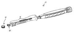
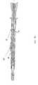
- FIG. 1Ais a perspective view of an exemplary embodiment of a spinal implant insertion device
- FIG. 1Bis a partially exploded view of the device of FIG. 1A ;
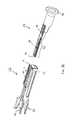
- FIG. 2Ais a perspective view of an exemplary embodiment of an insertion blade assembly
- FIG. 2Bis an exploded view of the insertion blade assembly of FIG. 2A ;
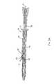
- FIG. 3Ais a cross-sectional view of the device of FIG. 1 showing the insertion blade assembly locked relative to the elongate shaft in an extended position;
- FIG. 3Bis a cross-sectional view of the device of FIG. 1 showing the insertion blade assembly sliding from the extended to retracted position;
- FIG. 3Cis another cross-sectional view of the device of FIG. 1 showing the insertion blade assembly locked in the retracted position;
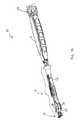
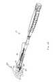
- FIG. 4is another partially exploded view of the device of FIG. 1 ;
- FIG. 5is a perspective view of an exemplary embodiment of a grasper element
- FIG. 6Ais a perspective view of the device of FIG. 1 approaching a spinal implant
- FIG. 6Bis a view of the device of FIG. 1 wherein the spinal implant is securely engaged by the grasper element;
- FIG. 6Cis a view of the device of FIG. 1 wherein the insertion blade assembly is in the extended position
- FIG. 6Dis a view of the device of FIG. 1 wherein the implant is positioned within a desired anatomical location;
- FIG. 6Eis a view of the device of FIG. 1 wherein the insertion blade assembly is moved to a retracted position after placement of the implant;
- FIG. 6Fis a view of the device of FIG. 1 wherein the device is withdrawn from the anatomical location.
- FIGS. 1A-1Bprovide an exemplary embodiment of a spinal implant insertion device 10 .
- the device 10includes an elongate shaft 12 extending from a handle 16 portion. More specifically, the elongate shaft 12 includes a proximal end ( 12 P ) extending from a distal portion of the handle 16 , and the shaft 12 terminates in a distal end ( 12 D ) having an opening (see element 62 in FIG. 4 ) in communication with an inner lumen (not shown) extending within the shaft 12 between its proximal ( 12 P ) and distal ends ( 12 D ).
- the device 10further includes an insertion blade assembly 18 slidably engaged to the elongate shaft 12 .
- a distal portion of the insertion blade assembly 18includes a set of opposed blades 26 , 28 configured to be positioned on opposite sides of a longitudinal axis 11 (see FIG. 3A ) of the shaft 12 .
- the insertion blade assembly 18can slide from a retracted position (as shown, for example, in FIG. 1A ) to an extended position (as shown, for example, in FIG. 6C ).
- the distal end of the blades 26 , 28are positioned proximal of an implant held by the device 10
- at least a distal portion of the blades 26 , 28are positioned above and/or below at least a portion of a spinal implant held by the device 10 so as to shield the implant from respective vertebral endplates during positioning within an intervertebral space.
- the device 10further includes a grasper element 20 adapted to grasp and release the spinal implant.
- a proximal portion 60 of the grasper element 20can be disposed within the distal opening of the shaft 12 so as to couple the grasper element 20 to the device 10 .
- the grasper element 20can further be coupled to an actuator 22 (via a connector element discussed below) such that an external force (e.g., a rotational force) applied to the actuator 22 can force the grasper element 20 to open and close so as to grasp and/or release a spinal implant.
- an external forcee.g., a rotational force
- FIGS. 2A and 2Bprovide an exemplary embodiment of the insertion blade assembly 18 .
- the insertion blade assembly 18generally includes an assembly shaft 30 which extends into a set of opposed insertion blades 26 , 28 .
- the set of insertion bladesincludes a first insertion blade 26 positioned above a longitudinal axis 11 (substantially collinear with longitudinal axis of shaft 12 ) of the assembly shaft 30 , and a second insertion blade 28 positioned below the longitudinal axis 11 of the assembly shaft 30 .
- the top blade 26 and the bottom blade 28can be an equal distance above and below the longitudinal axis, respectively.
- the top or bottom blade 26can be positioned closer to or further from the longitudinal axis of the assembly shaft 30 as compared to the corresponding blade 28 .
- the blades 26 , 28can be positioned relative to one another in any manner as required by a given procedure.
- each blade 26 , 28 of the insertion blade assembly 18can have any of a wide range of possible configurations, sizes, dimensions, etc.
- the blades 26 , 28can have any configuration capable of shielding a portion of a spinal implant from respective vertebral endplates as the implant is positioned within an intervertebral space.
- at least one of the first and second insertion blades 26 , 28can be substantially planar.
- at least one of the first and second insertion blades 26 , 28have a substantially “U-shaped” configuration wherein each plate 26 , 28 includes a distal-facing opening 27 .
- At least one of the insertion blades 26can include a first portion 26 a adapted to shield a first set of protrusions positioned along one surface (e.g., a right surface) of a spinal implant, and a second portion 26 b of the blade 26 can be adapted to shield a second set of protrusions positioned along an opposite surface (e.g., a left surface) of the spinal implant.
- the blades 26 , 28can have any such configuration so as to correspond to any pattern of protrusions formed on an implant.
- the blades 26 , 28can be configured to provide additional benefits.
- the distal-facing opening 27can provide for cost savings by using less material.
- the opening 27provides enhanced visibility to a user thereby allowing for better positioning of the implant within the intervertebral space.
- the first and second insertion blades 26 , 28can be substantially identical in size, shape, configuration, etc., or the blades 26 , 28 can be distinct in one or all of these variables. Any such combination of insertion blades 26 , 28 is within the spirit and scope of the present invention. Additionally, the blades 26 , 28 can include a wide range of dimensions. For example, referring to FIG. 2B , a length (“L”) of the insertion blade 26 can be in the range of about 16 mm to about 24 mm. Those skilled in the art will appreciate that such insertion blades 26 , 28 of any dimensions are within the spirit and scope of the present invention.
- the insertion blade assembly 18can be a one-piece assembly, or the assembly 18 can be a modular design wherein various insertion blade portions can be releasably engaged to a single handle portion to form a complete insertion blade assembly 18 .
- the insertion blade portion 22can release from a handle portion 24 .
- Such an embodimentallows for a wide range of insertion blades 26 , 28 having different sizes, shapes, dimensions, configurations, etc. to be engaged to the handle portion 24 thereby providing a versatile device capable of being utilized with several implants and/or procedures.
- a wide range of mechanismscan be utilized to releasably mate the insertion blade portion 22 and the handle portion 24 .
- the extension 32includes a central opening 38 which terminates with a distal bar 36 .
- the distal end of the extension 32is inserted into a groove 40 configured to accept the extension 32 .
- the distal bar 36encounters a locking element 42 .
- the locking element 42includes a ramped proximal end, and the locking element 42 is biased in an upward position (i.e., locking mechanism 42 can move downward in response to a force).
- the insertion blade portion 22is now securely coupled to the handle portion 24 to form a complete insertion blade assembly 18 capable of being slidably mounted to the central shaft 12 of the spinal insertion device 10 .
- the device 10can be adapted to include a locking mechanism capable of locking the insertion blade assembly 18 relative to the elongate shaft 12 of the device 10 at least one desired position (for example, at the extended position and/or the retracted position).
- a locking mechanismcapable of locking the insertion blade assembly 18 relative to the elongate shaft 12 of the device 10 at least one desired position (for example, at the extended position and/or the retracted position).
- Various such locking mechanismsare within the spirit and scope of the present invention.
- a bottom portion of the locking element 42can be adapted to engage a first groove 50 (see FIG. 1B ) incorporated into the elongate shaft 12 .
- the distal bar 36(discussed above) is positioned immediately distal of a pointed distal portion of the locking element 42 .
- the distal bar 36can lift the locking element 42 to a necessary height so as to allow the locking element 42 to exit the groove 50 and slide in a proximal direction.
- FIG. 3Bas the assembly 18 is positioned between the extended and retracted positions, the locking element 42 is free to slide along the elongate shaft 12 due to the absence of any grooves in the shaft.
- a second locking element 52(also see FIG. 2B ) is free to move in a proximal direction along the shaft.
- the second locking mechanism 52eventually engages a second groove 54 (also, see FIG. 1B ) incorporated into the elongate shaft 12 .
- the second locking mechanism 52can prevent the assembly 18 from moving distally thereby locking the assembly 18 in the retracted position.
- the locking mechanisms 42 , 52are adapted such that a minimal proximal or distal force applied to the terminal flange 34 can “unlock” the locking mechanism.
- any such locking mechanism capable of securing the assembly at any desired locationis within the spirit and scope of the present invention.
- the devicecan be adapted to not utilize any type of locking mechanism but rather rely on the user to properly position and secure the insertion blade assembly 18 .
- the device 10further includes a grasper element 20 adapted to grasp a spinal implant, position the implant within a desired anatomical location (e.g., an intervertebral space), and subsequently release the implant.
- a grasper element 20can include a proximal portion 60 configured to be disposed within a distal opening 62 of the elongate shaft 12 (as indicated by the exploded view of FIG. 4 ). As shown in FIG.
- the grasper element 20includes a first jaw 66 and a second jaw 68 adapted to move (as shown by double-headed arrow in FIG. 5 ) between a first, open position and a second, closed position wherein the jaws 66 , 68 can grasp a spinal implant when in the closed position.
- a connector 74(as shown in FIG. 3A ) extends from an actuator 22 to a proximal portion of the grasper element 20 .
- the distal end 74 ′ of the connector 74can include a threaded portion adapted to engage a corresponding thread of an inner lumen 64 of the grasper element 20 .
- the corresponding threads“pull” the grasper element 20 in a proximal direction so that the grasper element 20 is pulled further into the distal opening 62 of the elongate shaft 12 .
- the walls of the shaft 12apply a force to the grasper element 20 because the width (“W” in FIG. 5 ) is greater than the diameter of the distal opening 62 .
- a central slit 70 of the grasper element 20allows for the jaws 66 , 68 to move towards one another in response to the force supplied by the walls of the elongate shaft 12 .
- the jaws 66 , 68can be forced together until they securely grasp an implant.
- the actuator 22is rotated in a reverse direction such that the grasper is “pushed out” of the distal opening 62 of the elongate shaft 12 .
- the grasper element 20moves distally, the force applied by the walls of the shaft 12 dissipates such that the jaws 66 , 68 open up (i.e., move away from one another and return to a biased, open position) thereby releasing the implant.
- the grasper element 20can be configured to allow for enhanced visibility by a user so that the implant can be properly positioned within the intervertebral space.
- the grasper element 20can include at least one side opening 72 thereby allowing the user to visualize the position of the implant during insertion to the intervertebral space.
- the grasper element 20can include at least one side opening 72 thereby allowing the user to visualize the position of the implant during insertion to the intervertebral space.
- various other grasper elements and mechanisms for opening/closing the jaws of the grasper elementare within the spirit and scope of the present invention such as those disclosed in Assignees' co-pending U.S. patent application Ser. No. 10/750,173, filed on Dec. 31, 2003, entitled “Inserter Instrument and Implant Clip,” the entirety of which is hereby incorporated herein by reference.
- FIGS. 6A-6Fprovide an illustrative example showing a spinal implant 80 being positioned within an intervertebral space.
- the insertion blade assembly 18can be in a retracted position with the jaws of the grasper element 20 in an open position.
- the device 10can be utilized to grasp the spinal implant 80 (e.g., an artificial disc.)
- the jaws of the grasper element 20have moved from an open position to a closed position by applying a rotational force to the actuator 22 .
- the spinal implant 80is held within the grasping element 20 .
- FIG. 6Ainitially, the insertion blade assembly 18 can be in a retracted position with the jaws of the grasper element 20 in an open position. In this configuration, the device 10 can be utilized to grasp the spinal implant 80 (e.g., an artificial disc.)
- the jaws of the grasper element 20have moved from an open position to a closed position by applying a rotational force to the actuator 22 .
- the spinal implant 80is held within the grasping element
- the insertion blade assembly 18is slid from a retracted position to an extended position by application of a distal force to the terminal flange 34 .
- the distal portion of the insertion blades 66 , 68are adapted to be positioned above and below at least a portion of the superior and inferior surfaces of the implant 80 thereby shielding portions of the implant 80 from respective vertebral endplates of adjacent vertebrae.
- the blades 66 , 68shield a set of anterior and central teeth of the implant 80 .
- the spinal implantis positioned between adjacent vertebrae 82 and 84 .
- a portion of the top blade 66is positioned between the superior surface of the implant 80 and the superior vertebrae 82
- a portion of the bottom blade 68is positioned between the inferior surface of the implant 80 and the inferior vertebra 84 thereby shielding the implant from respective vertebral endplates of the adjacent vertebra 82 , 84 .
- the insertion blade assembly 18can be slid from the extended position to the retracted position thereby removing any portion of the assembly 18 from the intervertebral space, and allowing the implant 80 (as well as any associated protrusions/teeth) to engage the respective vertebral endplate of adjacent vertebrae 82 , 84 .
- an opposite rotational force(as compared to the initial rotational force) can be applied to the actuator to move the jaws of the grasper element 20 from the closed position to the open position thereby releasing the spinal implant.
- the grasper element 20releases the implant, as shown in FIG. 6F , the device 10 can be withdrawn from the treatment area.
- the various components discussed abovecan be formed from commonly known sterilizable, biocompatible materials.
- the various componentscan be formed from any combination of polymers, metals, and metal alloys. Those skilled in the art will appreciate that these are merely examples and any such materials or combination of materials are within the spirit and scope of the present invention.
- a method for positioning a spinal implant within an anatomical locationallows for portions of an implant to be shielded from respective vertebral endplates of adjacent vertebrae as the implant is positioned within an intervertebral space. More specifically, the method includes grasping a spinal implant with a spinal implant insertion device. Once the implant is held by the device, the method includes sliding a pair of opposed insertion blades along an elongate shaft of the insertion device from a retracted position to an extended position such that in the extended position a top blade is positioned above a portion of the spinal implant and a bottom blade is positioned below a corresponding portion of the spinal implant.
- the methodincludes positioning the implant within the desired anatomical location (e.g., an intervertebral space), and sliding the blades from the extended position to the retracted position. Finally, the method includes releasing the spinal implant from the spinal implant insertion device. Additionally, the method can include locking the opposed insertion blades to the elongate shaft of the spinal insertion device when the blades are in a desired position (i.e., the extended position or the retracted position). In an exemplary embodiment, any step of the method can be performed utilizing any of the embodiments of the device described in detail above.
- the desired anatomical locatione.g., an intervertebral space
- the methodincludes releasing the spinal implant from the spinal implant insertion device. Additionally, the method can include locking the opposed insertion blades to the elongate shaft of the spinal insertion device when the blades are in a desired position (i.e., the extended position or the retracted position). In an exemplary embodiment, any step of the method can be performed utilizing any of the embodiments
Landscapes
- Health & Medical Sciences (AREA)
- Engineering & Computer Science (AREA)
- Biomedical Technology (AREA)
- Life Sciences & Earth Sciences (AREA)
- General Health & Medical Sciences (AREA)
- Veterinary Medicine (AREA)
- Heart & Thoracic Surgery (AREA)
- Transplantation (AREA)
- Orthopedic Medicine & Surgery (AREA)
- Animal Behavior & Ethology (AREA)
- Surgery (AREA)
- Public Health (AREA)
- Neurology (AREA)
- Nuclear Medicine, Radiotherapy & Molecular Imaging (AREA)
- Molecular Biology (AREA)
- Physical Education & Sports Medicine (AREA)
- Medical Informatics (AREA)
- Cardiology (AREA)
- Oral & Maxillofacial Surgery (AREA)
- Vascular Medicine (AREA)
- Prostheses (AREA)
Abstract
Description
Claims (8)
Priority Applications (1)
| Application Number | Priority Date | Filing Date | Title |
|---|---|---|---|
| US11/750,470US8579910B2 (en) | 2007-05-18 | 2007-05-18 | Insertion blade assembly and method of use |
Applications Claiming Priority (1)
| Application Number | Priority Date | Filing Date | Title |
|---|---|---|---|
| US11/750,470US8579910B2 (en) | 2007-05-18 | 2007-05-18 | Insertion blade assembly and method of use |
Publications (2)
| Publication Number | Publication Date |
|---|---|
| US20080287957A1 US20080287957A1 (en) | 2008-11-20 |
| US8579910B2true US8579910B2 (en) | 2013-11-12 |
Family
ID=40028296
Family Applications (1)
| Application Number | Title | Priority Date | Filing Date |
|---|---|---|---|
| US11/750,470Active2030-07-17US8579910B2 (en) | 2007-05-18 | 2007-05-18 | Insertion blade assembly and method of use |
Country Status (1)
| Country | Link |
|---|---|
| US (1) | US8579910B2 (en) |
Cited By (2)
| Publication number | Priority date | Publication date | Assignee | Title |
|---|---|---|---|---|
| US20140188226A1 (en)* | 2012-12-26 | 2014-07-03 | Spineworks Llc | Interbody insertion tool and method |
| US11793558B2 (en) | 2019-08-30 | 2023-10-24 | K2M, Inc. | All in one plate holder and spring loaded awl |
Families Citing this family (49)
| Publication number | Priority date | Publication date | Assignee | Title |
|---|---|---|---|---|
| WO2009055541A1 (en)* | 2007-10-23 | 2009-04-30 | K2M, Inc. | Implant insertion tool |
| US8591587B2 (en) | 2007-10-30 | 2013-11-26 | Aesculap Implant Systems, Llc | Vertebral body replacement device and method for use to maintain a space between two vertebral bodies within a spine |
| US8142441B2 (en)* | 2008-10-16 | 2012-03-27 | Aesculap Implant Systems, Llc | Surgical instrument and method of use for inserting an implant between two bones |
| US8182537B2 (en) | 2007-10-30 | 2012-05-22 | Aesculap Implant Systems, Llc | Vertebral body replacement device and method for use to maintain a space between two vertebral bodies within a spine |
| US8216317B2 (en) | 2008-03-31 | 2012-07-10 | Stryker Spine | Spinal implant apparatus and methods |
| US8382767B2 (en)* | 2008-10-31 | 2013-02-26 | K2M, Inc. | Implant insertion tool |
| US8142435B2 (en)* | 2009-02-19 | 2012-03-27 | Aesculap Implant Systems, Llc | Multi-functional surgical instrument and method of use for inserting an implant between two bones |
| USD599479S1 (en)* | 2009-03-13 | 2009-09-01 | Orthopedic Development Corporation | Surgical inserter |
| US10842642B2 (en) | 2009-04-16 | 2020-11-24 | Nuvasive, Inc. | Methods and apparatus of performing spine surgery |
| US9351845B1 (en)* | 2009-04-16 | 2016-05-31 | Nuvasive, Inc. | Method and apparatus for performing spine surgery |
| US8529627B2 (en)* | 2009-07-02 | 2013-09-10 | Atlas Spine, Inc. | Intervertebral spacer |
| US9642722B2 (en) | 2009-07-02 | 2017-05-09 | Atlas Spine, Inc. | Intervertebral expandable spacer |
| US9480511B2 (en) | 2009-12-17 | 2016-11-01 | Engage Medical Holdings, Llc | Blade fixation for ankle fusion and arthroplasty |
| US8858636B2 (en) | 2010-04-09 | 2014-10-14 | DePuy Synthes Products, LLC | Intervertebral implant |
| US9301853B2 (en)* | 2010-04-09 | 2016-04-05 | DePuy Synthes Products, Inc. | Holder for implantation and extraction of prosthesis |
| US8808304B2 (en) | 2010-04-21 | 2014-08-19 | Globus Medical, Inc | Insertion tool assembly |
| US12226322B2 (en)* | 2010-04-21 | 2025-02-18 | Globus Medical, Inc. | Implant packaging cartridge and insertion tool |
| US12150865B2 (en) | 2010-04-21 | 2024-11-26 | Globus Medical, Inc. | Implant packaging cartridge and insertion tool |
| US8425529B2 (en) | 2010-09-30 | 2013-04-23 | Stryker Spine | Instrument for inserting surgical implant with guiding rail |
| US8603175B2 (en) | 2010-09-30 | 2013-12-10 | Stryker Spine | Method of inserting surgical implant with guiding rail |
| US8858637B2 (en) | 2010-09-30 | 2014-10-14 | Stryker Spine | Surgical implant with guiding rail |
| GB2486020A (en) | 2010-12-02 | 2012-06-06 | Biomet Uk Healthcare Ltd | Impaction tool for manipulating an implant |
| EP2651341B1 (en) | 2010-12-16 | 2017-01-04 | Engage Medical Holdings, LLC | Arthroplasty systems and methods |
| EP2517675B1 (en)* | 2011-04-29 | 2016-08-03 | Medacta International S.A. | Instrument for positioning an intervertebral implant for the fusion between two vertebral bodies of a vertebral column |
| FR2981264B1 (en)* | 2011-10-17 | 2013-11-29 | Osteal Medical Lab | INTERVERTEBRAL IMPLANT GRIPPER, KIT AND MANIPULATION ASSEMBLY THEREFOR |
| US9254130B2 (en) | 2011-11-01 | 2016-02-09 | Hyun Bae | Blade anchor systems for bone fusion |
| US9615856B2 (en) | 2011-11-01 | 2017-04-11 | Imds Llc | Sacroiliac fusion cage |
| US10238382B2 (en) | 2012-03-26 | 2019-03-26 | Engage Medical Holdings, Llc | Blade anchor for foot and ankle |
| CN102908214B (en)* | 2012-09-21 | 2015-01-28 | 联合骨科器材股份有限公司 | Acetabular cup implanter |
| ES2544274T3 (en)* | 2012-10-24 | 2015-08-28 | Waldemar Link Gmbh & Co. Kg | Support for a medical implant |
| US20140172104A1 (en)* | 2012-12-18 | 2014-06-19 | Alphatec Spine, Inc. | Instrument for insertion and deployment of an implant |
| US8864830B2 (en) | 2013-03-12 | 2014-10-21 | Spine Wave, Inc. | Apparatus and methods for inserting an interbody fusion device |
| US9642723B2 (en)* | 2014-02-27 | 2017-05-09 | Alphatec Spine, Inc. | Spinal implants and insertion instruments |
| GB201405414D0 (en) | 2014-03-26 | 2014-05-07 | Northwood Medical Innovations Ltd | Surgical introducer |
| US9681961B2 (en)* | 2014-08-01 | 2017-06-20 | Warsaw Orthopedic, Inc. | Surgical instrument system and method |
| US10390955B2 (en) | 2016-09-22 | 2019-08-27 | Engage Medical Holdings, Llc | Bone implants |
| US10456272B2 (en) | 2017-03-03 | 2019-10-29 | Engage Uni Llc | Unicompartmental knee arthroplasty |
| US11540928B2 (en) | 2017-03-03 | 2023-01-03 | Engage Uni Llc | Unicompartmental knee arthroplasty |
| US10716684B2 (en)* | 2017-06-14 | 2020-07-21 | Vertebration, Inc. | Spine surgery method and instrumentation |
| US10888435B2 (en)* | 2017-10-05 | 2021-01-12 | Spine Wave, Inc. | Modular inserter for anterior cervical cage |
| CN113194886B (en)* | 2018-11-08 | 2024-11-22 | 尼奥医疗公司 | Spinal fusion hammer |
| US11298244B2 (en)* | 2019-01-31 | 2022-04-12 | K2M, Inc. | Interbody implants and instrumentation |
| NL2023241B1 (en) | 2019-05-31 | 2020-12-07 | Petrus Stegmann Johann | Intervertebral fusion cage |
| US11452617B2 (en)* | 2019-09-09 | 2022-09-27 | Integrity Implants Inc. | Dynamic expanding pathway cannula |
| US11534307B2 (en) | 2019-09-16 | 2022-12-27 | K2M, Inc. | 3D printed cervical standalone implant |
| US11883303B2 (en) | 2019-12-30 | 2024-01-30 | Vertebration, Inc. | Spine surgery method and instrumentation |
| US11517363B2 (en) | 2020-11-05 | 2022-12-06 | Warsaw Orthopedic, Inc. | Screw driver and complimentary screws |
| US20230293314A1 (en)* | 2021-06-24 | 2023-09-21 | Warsaw Orthopedic, Inc. | Parallel jaw inserter |
| WO2022271280A1 (en) | 2021-06-24 | 2022-12-29 | Warsaw Orthopedic, Inc. | Expandable interbody implant and corresponding surgical tool |
Citations (153)
| Publication number | Priority date | Publication date | Assignee | Title |
|---|---|---|---|---|
| US3141583A (en) | 1962-03-23 | 1964-07-21 | William L Brickson | Injection gun |
| US3752161A (en) | 1971-08-02 | 1973-08-14 | Minnesota Mining & Mfg | Fluid operated surgical tool |
| US3835860A (en) | 1973-06-21 | 1974-09-17 | H Garretson | Surgical bone punch |
| US4367746A (en) | 1979-12-11 | 1983-01-11 | Derechinsky Victor E | Clip-holder instrument for clipping blood vessels |
| US4512345A (en) | 1982-09-30 | 1985-04-23 | United States Surgical Corporation | Surgical clip applying apparatus, and clips and clip train for use therein |
| US4759766A (en) | 1984-09-04 | 1988-07-26 | Humboldt-Universitaet Zu Berlin | Intervertebral disc endoprosthesis |
| FR2636227A1 (en) | 1988-09-09 | 1990-03-16 | Fabrication Materiel Orthopedi | Inter-spinal-body device for holding a normal spacing between two vertebrae |
| US5122130A (en) | 1988-03-23 | 1992-06-16 | Waldemar Link Gmbh & Co. | Forceps for inserting intervertebral device |
| EP0535973A1 (en) | 1991-10-04 | 1993-04-07 | JOHNSON & JOHNSON ORTHOPAEDICS, INC. | An acetabular cup inserter |
| US5236460A (en) | 1990-02-12 | 1993-08-17 | Midas Rex Pneumatic Tools, Inc. | Vertebral body prosthesis |
| US5258031A (en) | 1992-01-06 | 1993-11-02 | Danek Medical | Intervertebral disk arthroplasty |
| US5300081A (en) | 1992-10-09 | 1994-04-05 | United States Surgical Corporation | Surgical clip applier having clip advancement control |
| US5314477A (en) | 1990-03-07 | 1994-05-24 | J.B.S. Limited Company | Prosthesis for intervertebral discs and instruments for implanting it |
| US5360430A (en) | 1993-07-29 | 1994-11-01 | Lin Chih I | Intervertebral locking device |
| US5370697A (en) | 1992-04-21 | 1994-12-06 | Sulzer Medizinaltechnik Ag | Artificial intervertebral disk member |
| EP0630615A1 (en) | 1993-06-16 | 1994-12-28 | Lerch, Karl-Dieter, Dr. med. | Set for treatment of vessel deformities |
| US5425773A (en) | 1992-01-06 | 1995-06-20 | Danek Medical, Inc. | Intervertebral disk arthroplasty device |
| US5431658A (en) | 1994-02-14 | 1995-07-11 | Moskovich; Ronald | Facilitator for vertebrae grafts and prostheses |
| US5431654A (en) | 1991-09-30 | 1995-07-11 | Stryker Corporation | Bone cement injector |
| FR2717068A1 (en) | 1994-03-14 | 1995-09-15 | Biomat | Intersomatic cage insertable between two vertebral bodies |
| US5458641A (en) | 1993-09-08 | 1995-10-17 | Ramirez Jimenez; Juan J. | Vertebral body prosthesis |
| US5505732A (en) | 1988-06-13 | 1996-04-09 | Michelson; Gary K. | Apparatus and method of inserting spinal implants |
| US5507816A (en) | 1991-12-04 | 1996-04-16 | Customflex Limited | Spinal vertebrae implants |
| WO1996022747A1 (en) | 1995-01-24 | 1996-08-01 | Stryker Corporation | Interbody cavity type implant, and instrumentation and method for positioning same |
| US5591170A (en) | 1994-10-14 | 1997-01-07 | Genesis Orthopedics | Intramedullary bone cutting saw |
| US5676701A (en) | 1993-01-14 | 1997-10-14 | Smith & Nephew, Inc. | Low wear artificial spinal disc |
| WO1997038634A1 (en) | 1996-04-18 | 1997-10-23 | Applied Medical Resources Corporation | Malleable clip applier and method |
| US5683465A (en) | 1996-03-18 | 1997-11-04 | Shinn; Gary Lee | Artificial intervertebral disk prosthesis |
| US5782832A (en) | 1996-10-01 | 1998-07-21 | Surgical Dynamics, Inc. | Spinal fusion implant and method of insertion thereof |
| US5782830A (en) | 1995-10-16 | 1998-07-21 | Sdgi Holdings, Inc. | Implant insertion device |
| US5797927A (en) | 1995-09-22 | 1998-08-25 | Yoon; Inbae | Combined tissue clamping and suturing instrument |
| US5851207A (en) | 1997-07-01 | 1998-12-22 | Synthes (U.S.A.) | Freely separable surgical drill guide and plate |
| US5873886A (en) | 1995-04-04 | 1999-02-23 | United States Surgical Corporation | Surgical cutting apparatus |
| US5895428A (en) | 1996-11-01 | 1999-04-20 | Berry; Don | Load bearing spinal joint implant |
| US5899941A (en) | 1997-12-09 | 1999-05-04 | Chubu Bearing Kabushiki Kaisha | Artificial intervertebral disk |
| US5931849A (en) | 1997-05-06 | 1999-08-03 | Visco | Modular surgery device for endoscopic surgery and standard surgery |
| US5938678A (en) | 1997-06-11 | 1999-08-17 | Endius Incorporated | Surgical instrument |
| US5989291A (en) | 1998-02-26 | 1999-11-23 | Third Millennium Engineering, Llc | Intervertebral spacer device |
| US6019792A (en) | 1998-04-23 | 2000-02-01 | Cauthen Research Group, Inc. | Articulating spinal implant |
| US6063121A (en) | 1998-07-29 | 2000-05-16 | Xavier; Ravi | Vertebral body prosthesis |
| US6099550A (en) | 1989-12-05 | 2000-08-08 | Yoon; Inbae | Surgical instrument having jaws and an operating channel and method for use thereof |
| US6110179A (en) | 1998-03-02 | 2000-08-29 | Benoist Girard Sas | Prosthesis inserter |
| US6113637A (en) | 1998-10-22 | 2000-09-05 | Sofamor Danek Holdings, Inc. | Artificial intervertebral joint permitting translational and rotational motion |
| US6113605A (en) | 1998-03-02 | 2000-09-05 | Benoist Girard & Cie | Prosthesis inserter |
| US6146421A (en) | 1997-08-04 | 2000-11-14 | Gordon, Maya, Roberts And Thomas, Number 1, Llc | Multiple axis intervertebral prosthesis |
| US6159215A (en) | 1997-12-19 | 2000-12-12 | Depuy Acromed, Inc. | Insertion instruments and method for delivering a vertebral body spacer |
| US6174311B1 (en) | 1998-10-28 | 2001-01-16 | Sdgi Holdings, Inc. | Interbody fusion grafts and instrumentation |
| US6179874B1 (en) | 1998-04-23 | 2001-01-30 | Cauthen Research Group, Inc. | Articulating spinal implant |
| US6228118B1 (en) | 1997-08-04 | 2001-05-08 | Gordon, Maya, Roberts And Thomas, Number 1, Llc | Multiple axis intervertebral prosthesis |
| US6261296B1 (en) | 1998-10-02 | 2001-07-17 | Synthes U.S.A. | Spinal disc space distractor |
| US20010016741A1 (en)* | 2000-02-04 | 2001-08-23 | Burkus J. Kenneth | Methods and instrumentation for vertebral interbody fusion |
| US6296665B1 (en) | 2000-03-20 | 2001-10-02 | Electro-Biology, Inc. | Method and apparatus for spinal fixation |
| US6319257B1 (en) | 1999-12-20 | 2001-11-20 | Kinamed, Inc. | Inserter assembly |
| US20020011687A1 (en) | 2000-04-18 | 2002-01-31 | Mischo Donald J. | Methods and apparatus for recycling asphalt shingle material into shaped products |
| US6358268B1 (en) | 2000-03-06 | 2002-03-19 | Robert B. Hunt | Surgical instrument |
| US20020035400A1 (en) | 2000-08-08 | 2002-03-21 | Vincent Bryan | Implantable joint prosthesis |
| US6368350B1 (en) | 1999-03-11 | 2002-04-09 | Sulzer Spine-Tech Inc. | Intervertebral disc prosthesis and method |
| US6371986B1 (en) | 1998-10-27 | 2002-04-16 | George W. Bagby | Spinal fusion device, bone joining implant, and vertebral fusion implant |
| US6375682B1 (en) | 2001-08-06 | 2002-04-23 | Lewis W. Fleischmann | Collapsible, rotatable and expandable spinal hydraulic prosthetic device |
| US6395034B1 (en) | 1999-11-24 | 2002-05-28 | Loubert Suddaby | Intervertebral disc prosthesis |
| US6416551B1 (en) | 1999-05-21 | 2002-07-09 | Waldemar Link (Gmbh & Co.) | Intervertebral endoprosthesis with a toothed connection plate |
| US20020111685A1 (en) | 2001-02-15 | 2002-08-15 | Ralph James D. | Intervertebral spacer device utilizing a spirally slotted belleville washer having radially spaced concentric grooves |
| US20020111686A1 (en) | 2001-02-15 | 2002-08-15 | Ralph James D. | Intervertebral spacer device utilizing a spirally slotted belleville washer and a rotational mounting |
| US20020111682A1 (en) | 2001-02-15 | 2002-08-15 | Ralph James D. | Intervertebral spacer device having a radially thinning belleville spring |
| US20020111681A1 (en) | 2001-02-15 | 2002-08-15 | Ralph James D. | Intervertebral spacer device having a radially thinning slotted belleville spring |
| US20020111679A1 (en) | 1998-10-20 | 2002-08-15 | Zucherman James F. | Apparatus and method for determining implant size |
| US20020111683A1 (en) | 2001-02-15 | 2002-08-15 | Ralph James D. | Intervertebral spacer device utilizing a spirally slotted belleville washer having radially extending grooves |
| US20020111684A1 (en) | 2001-02-15 | 2002-08-15 | Ralph James D. | Intervertebral spacer device utilizing a belleville washer having radially spaced concentric grooves |
| US20020116009A1 (en) | 2000-05-08 | 2002-08-22 | Fraser Robert D. | Medical installation tool |
| US6440142B1 (en) | 2001-04-27 | 2002-08-27 | Third Millennium Engineering, Llc | Femoral ring loader |
| US6439439B1 (en) | 2001-01-12 | 2002-08-27 | Telios Orthopedic Systems, Inc. | Bone cement delivery apparatus and hand-held fluent material dispensing apparatus |
| US20020128714A1 (en) | 1999-06-04 | 2002-09-12 | Mark Manasas | Orthopedic implant and method of making metal articles |
| US20020128715A1 (en) | 2000-08-08 | 2002-09-12 | Vincent Bryan | Implantable joint prosthesis |
| US20020128659A1 (en) | 2001-03-01 | 2002-09-12 | Michelson Gary K. | Dynamic lordotic guard with movable extensions for creating an implantation space posteriorly in the lumbar spine and method for use thereof |
| US20020161366A1 (en) | 2000-12-29 | 2002-10-31 | Bruce Robie | Instrument system for preparing a disc space between adjacent vertebral bodies to receive a repair device |
| US20020173813A1 (en) | 2001-04-05 | 2002-11-21 | Peterson Francis C. | Circumferential resecting reamer tool |
| US6517544B1 (en) | 1998-06-09 | 2003-02-11 | Gary K. Michelson | Device and method for preparing a space between adjacent vertebrae to receive an insert |
| US6517580B1 (en) | 2000-03-03 | 2003-02-11 | Scient'x Societe A Responsabilite Limited | Disk prosthesis for cervical vertebrae |
| US20030033016A1 (en) | 2001-08-07 | 2003-02-13 | Gyrus Group Plc | Implant sheath |
| US6520967B1 (en) | 1999-10-20 | 2003-02-18 | Cauthen Research Group, Inc. | Spinal implant insertion instrument for spinal interbody prostheses |
| US6520996B1 (en) | 1999-06-04 | 2003-02-18 | Depuy Acromed, Incorporated | Orthopedic implant |
| US6524312B2 (en) | 2000-01-06 | 2003-02-25 | Spinal Concepts, Inc. | Instrument and method for implanting an interbody fusion device |
| US20030040802A1 (en) | 2001-07-16 | 2003-02-27 | Errico Joseph P. | Artificial intervertebral disc having limited rotation using a captured ball and socket joint with a solid ball and compression locking post |
| US6527804B1 (en) | 1998-12-11 | 2003-03-04 | Dimso (Distribution Medicale Du Sud-Quest) | Intervertebral disk prosthesis |
| US20030055434A1 (en) | 2001-09-20 | 2003-03-20 | O'neil Michael J. | Medical inserter tool with slaphammer |
| US20030060687A1 (en) | 2001-09-25 | 2003-03-27 | Kleeman Thomas J. | Methods and devices for inserting and manipulating surgical instruments |
| US20030069586A1 (en) | 2001-07-16 | 2003-04-10 | Errico Joseph P. | Instrumentation and methods for use in implanting an artificial intervertebral disc |
| US20030069643A1 (en) | 2001-07-16 | 2003-04-10 | Ralph James D. | Tension bearing artificial disc providing a centroid of motion centrally located within an intervertebral space |
| US20030074076A1 (en) | 1999-10-08 | 2003-04-17 | Ferree Bret A. | Artificial intervertebral disc replacements with endplates |
| US20030074066A1 (en) | 2001-07-16 | 2003-04-17 | Errico Joseph P. | Artificial intervertebral disc having limited rotation using a captured ball and socket joint with a solid ball, a retaining cap, and an interference pin |
| US20030078666A1 (en) | 2001-10-18 | 2003-04-24 | Ralph James D. | Intervertebral spacer device having a slotted partial circular domed arch strip spring |
| US20030083747A1 (en) | 2001-10-30 | 2003-05-01 | Osteotech, Inc. | Bone implant and isertion tools |
| US6562074B2 (en) | 2001-10-17 | 2003-05-13 | Medicinelodge, Inc. | Adjustable bone fusion implant and method |
| US6579320B1 (en) | 1998-12-11 | 2003-06-17 | Stryker Spine | Intervertebral disc prosthesis with contact blocks |
| US20030135277A1 (en) | 2001-11-26 | 2003-07-17 | Sdgi Holdings, Inc. | Implantable joint prosthesis and associated instrumentation |
| US20030135278A1 (en) | 2002-01-17 | 2003-07-17 | Concept Matrix, Llc | Intervertebral disk prosthesis |
| US20030135375A1 (en) | 2002-01-14 | 2003-07-17 | Bloomstein Richard W. | Encoding speech segments for economical transmission and automatic playing at remote computers |
| US6599295B1 (en) | 1998-04-21 | 2003-07-29 | Tornier Sa | Device for setting and removing an implant such as a suture anchor |
| US6599294B2 (en) | 1999-01-30 | 2003-07-29 | Aesculap Ag & Co. Kg | Surgical instrument for introducing intervertebral implants |
| US20030149482A1 (en) | 1988-06-28 | 2003-08-07 | Sofamor Danek Group, Inc. | Artificial spinal fusion implants |
| US20030149438A1 (en) | 2001-04-30 | 2003-08-07 | Howmedica Osteonics Corp. | Insertion instrument |
| US20030171813A1 (en) | 2002-03-05 | 2003-09-11 | P. Douglas Kiester | Method and apparatus for providing an expandable spinal fusion cage |
| WO2003077808A2 (en) | 2002-03-11 | 2003-09-25 | Spinal Concepts, Inc. | Instrumentation and procedure for implanting spinal implant devices |
| US20030199872A1 (en) | 2002-04-17 | 2003-10-23 | Stryker Spine | Rod persuader |
| US6648891B2 (en) | 2001-09-14 | 2003-11-18 | The Regents Of The University Of California | System and method for fusing spinal vertebrae |
| US20030216744A1 (en) | 1999-10-18 | 2003-11-20 | Sulzer Spine-Tech Inc. | Spinal surgery instruments and methods |
| US6663637B2 (en) | 2001-01-02 | 2003-12-16 | Robert A Dixon | Vertebral distraction stabilizer |
| US6692501B2 (en) | 2000-12-14 | 2004-02-17 | Gary K. Michelson | Spinal interspace shaper |
| US20040039397A1 (en) | 2002-08-22 | 2004-02-26 | Helmut Weber | Medical tool |
| US6712818B1 (en) | 1997-02-11 | 2004-03-30 | Gary K. Michelson | Method for connecting adjacent vertebral bodies of a human spine with a plating system |
| WO2004041131A2 (en) | 2002-10-31 | 2004-05-21 | Spinal Concepts, Inc. | Movable disc implant |
| US6740087B2 (en) | 1999-04-06 | 2004-05-25 | Benjamin D. Knox | Spinal fusion instrumentation system |
| US20040176773A1 (en) | 2003-03-06 | 2004-09-09 | Rafail Zubok | Instrumentation and methods for use in implanting a cervical disc replacement device |
| WO2004089224A2 (en) | 2003-03-31 | 2004-10-21 | Depuy Spine, Inc. | Method and apparatus for artificial disc insertion |
| US20040215198A1 (en) | 2003-04-28 | 2004-10-28 | Spine Solutions, Inc. | Instruments and method for preparing an intervertebral space for receiving an artificial disc implant |
| US20040225295A1 (en) | 2001-07-16 | 2004-11-11 | Rafail Zubok | Wedge ramp distractor and related methods for use in implanting artificial intervertebral discs |
| US20040267275A1 (en)* | 2003-06-26 | 2004-12-30 | Cournoyer John R. | Spinal implant holder and rod reduction systems and methods |
| US20050015094A1 (en) | 2003-07-15 | 2005-01-20 | Cervitech, Inc. | Arrangement of a cervical prosthesis and insertion instrument |
| US20050015095A1 (en) | 2003-07-15 | 2005-01-20 | Cervitech, Inc. | Insertion instrument for cervical prostheses |
| US20050021040A1 (en) | 2003-07-21 | 2005-01-27 | Rudolf Bertagnoli | Vertebral retainer-distracter and method of using same |
| US20050021042A1 (en) | 2003-07-21 | 2005-01-27 | Theirry Marnay | Instruments and method for inserting an intervertebral implant |
| US20050033305A1 (en)* | 2003-07-08 | 2005-02-10 | Robert Schultz | Surgical instrument for handling an implant |
| US20050033428A1 (en) | 2003-08-04 | 2005-02-10 | Cervitech, Inc. | Cervical prosthesis with insertion instrument |
| US20050038511A1 (en) | 2003-08-15 | 2005-02-17 | Martz Erik O. | Transforaminal lumbar interbody fusion (TLIF) implant, surgical procedure and instruments for insertion of spinal implant in a spinal disc space |
| US20050043800A1 (en) | 2003-07-31 | 2005-02-24 | Paul David C. | Prosthetic spinal disc replacement |
| US20050043740A1 (en) | 2003-08-20 | 2005-02-24 | Haid Regis W. | Technique and instrumentation for preparation of vertebral members |
| US20050055098A1 (en) | 2003-09-10 | 2005-03-10 | Sdgi Holdings, Inc. | Artificial spinal discs and associated implantation and revision methods |
| US20050055031A1 (en) | 2003-09-10 | 2005-03-10 | Roy Lim | Devices and methods for inserting spinal implants |
| US20050119665A1 (en) | 2001-10-29 | 2005-06-02 | Arnold Keller | Instrumentation for insertion of an inter-vertebral prosthesis |
| US20050143749A1 (en) | 2003-12-31 | 2005-06-30 | Depuy Spine, Inc. | Inserter instrument and implant clip |
| US20050165408A1 (en) | 2004-01-26 | 2005-07-28 | Puno Rolando M. | Methods and instrumentation for inserting intervertebral grafts and devices |
| US6986772B2 (en) | 2001-03-01 | 2006-01-17 | Michelson Gary K | Dynamic lordotic guard with movable extensions for creating an implantation space posteriorly in the lumbar spine |
| US20060025777A1 (en) | 2004-07-28 | 2006-02-02 | Helmut Weber | Surgical instrument for the introduction of a multi-component intervertebral prosthesis |
| US20060030862A1 (en) | 2003-01-31 | 2006-02-09 | Spinalmotion, Inc. | Intervertebral prosthesis placement instrument |
| US20060030857A1 (en) | 2004-08-06 | 2006-02-09 | Spinalmotion, Inc. | Methods and apparatus for intervertebral disc prosthesis insertion |
| US20060036261A1 (en) | 2004-08-13 | 2006-02-16 | Stryker Spine | Insertion guide for a spinal implant |
| US7014617B2 (en) | 2002-09-20 | 2006-03-21 | Depuy Acromed, Inc. | Pivoted tensiometer for measuring tension in an intervertebral disc space |
| US20060064107A1 (en) | 2004-09-23 | 2006-03-23 | Rudi Bertagnoli | Distractor for lumbar insertion instrument |
| WO2006033067A2 (en) | 2004-09-23 | 2006-03-30 | Spine Solutions Inc. | System and method for an intervertebral implant |
| US20060089656A1 (en) | 2004-10-22 | 2006-04-27 | Sdgi Holdings, Inc. | Revision instruments |
| US20060195097A1 (en) | 2005-02-25 | 2006-08-31 | Evans David E | Implant insertion apparatus and method of use |
| US7118580B1 (en) | 1999-09-14 | 2006-10-10 | Spine Solutions Inc. | Instrument for inserting intervertebral implants |
| US20060241641A1 (en) | 2005-04-22 | 2006-10-26 | Sdgi Holdings, Inc. | Methods and instrumentation for distraction and insertion of implants in a spinal disc space |
| US7204851B2 (en) | 2000-08-30 | 2007-04-17 | Sdgi Holdings, Inc. | Method and apparatus for delivering an intervertebral disc implant |
| US20070116221A1 (en) | 2005-07-22 | 2007-05-24 | Lg Electronics Inc. | Mobile terminal and multimedia contents service providing system and method for call connection waiting using the same |
| US20070123904A1 (en) | 2005-10-31 | 2007-05-31 | Depuy Spine, Inc. | Distraction instrument and method for distracting an intervertebral site |
| US20070123903A1 (en) | 2005-10-31 | 2007-05-31 | Depuy Spine, Inc. | Medical Device installation tool and methods of use |
| US20070191857A1 (en) | 2006-01-31 | 2007-08-16 | Sdgi Holdings, Inc. | Spinal disc replacement surgical instrument and methods for use in spinal disc replacement |
| US20070213739A1 (en) | 2001-03-01 | 2007-09-13 | Sdgi Holdings, Inc. | Method for using dynamic lordotic guard with movable extensions for creating an implantation space posteriorly in the lumbar spine |
| US20070233153A1 (en) | 2006-03-17 | 2007-10-04 | Sdgi Holdings, Inc. | Instrumentation for distraction and insertion of implants in a spinal disc space |
| US20070233143A1 (en) | 2006-03-14 | 2007-10-04 | Sdgi Holdings, Inc. | Spinal disc space preparation instruments and methods for interbody spinal implants |
| US20080065095A1 (en) | 2001-11-30 | 2008-03-13 | Spinecore, Inc. | Distraction instrument for use in anterior cervical fixation surgery |
| US20080269764A1 (en)* | 2007-04-25 | 2008-10-30 | Spinal Elements, Inc. | Spinal implant distractor/inserter |
- 2007
- 2007-05-18USUS11/750,470patent/US8579910B2/enactiveActive
Patent Citations (199)
| Publication number | Priority date | Publication date | Assignee | Title |
|---|---|---|---|---|
| US3141583A (en) | 1962-03-23 | 1964-07-21 | William L Brickson | Injection gun |
| US3752161A (en) | 1971-08-02 | 1973-08-14 | Minnesota Mining & Mfg | Fluid operated surgical tool |
| US3835860A (en) | 1973-06-21 | 1974-09-17 | H Garretson | Surgical bone punch |
| US4367746A (en) | 1979-12-11 | 1983-01-11 | Derechinsky Victor E | Clip-holder instrument for clipping blood vessels |
| US4512345A (en) | 1982-09-30 | 1985-04-23 | United States Surgical Corporation | Surgical clip applying apparatus, and clips and clip train for use therein |
| US4759766A (en) | 1984-09-04 | 1988-07-26 | Humboldt-Universitaet Zu Berlin | Intervertebral disc endoprosthesis |
| US5122130A (en) | 1988-03-23 | 1992-06-16 | Waldemar Link Gmbh & Co. | Forceps for inserting intervertebral device |
| US5505732A (en) | 1988-06-13 | 1996-04-09 | Michelson; Gary K. | Apparatus and method of inserting spinal implants |
| US20030149482A1 (en) | 1988-06-28 | 2003-08-07 | Sofamor Danek Group, Inc. | Artificial spinal fusion implants |
| FR2636227A1 (en) | 1988-09-09 | 1990-03-16 | Fabrication Materiel Orthopedi | Inter-spinal-body device for holding a normal spacing between two vertebrae |
| US6099550A (en) | 1989-12-05 | 2000-08-08 | Yoon; Inbae | Surgical instrument having jaws and an operating channel and method for use thereof |
| US5236460A (en) | 1990-02-12 | 1993-08-17 | Midas Rex Pneumatic Tools, Inc. | Vertebral body prosthesis |
| US5314477A (en) | 1990-03-07 | 1994-05-24 | J.B.S. Limited Company | Prosthesis for intervertebral discs and instruments for implanting it |
| US5431654A (en) | 1991-09-30 | 1995-07-11 | Stryker Corporation | Bone cement injector |
| EP0535973A1 (en) | 1991-10-04 | 1993-04-07 | JOHNSON & JOHNSON ORTHOPAEDICS, INC. | An acetabular cup inserter |
| US5507816A (en) | 1991-12-04 | 1996-04-16 | Customflex Limited | Spinal vertebrae implants |
| US5562738A (en) | 1992-01-06 | 1996-10-08 | Danek Medical, Inc. | Intervertebral disk arthroplasty device |
| US5425773A (en) | 1992-01-06 | 1995-06-20 | Danek Medical, Inc. | Intervertebral disk arthroplasty device |
| US5258031A (en) | 1992-01-06 | 1993-11-02 | Danek Medical | Intervertebral disk arthroplasty |
| US5370697A (en) | 1992-04-21 | 1994-12-06 | Sulzer Medizinaltechnik Ag | Artificial intervertebral disk member |
| US5300081A (en) | 1992-10-09 | 1994-04-05 | United States Surgical Corporation | Surgical clip applier having clip advancement control |
| US5676701A (en) | 1993-01-14 | 1997-10-14 | Smith & Nephew, Inc. | Low wear artificial spinal disc |
| EP0630615A1 (en) | 1993-06-16 | 1994-12-28 | Lerch, Karl-Dieter, Dr. med. | Set for treatment of vessel deformities |
| US5360430A (en) | 1993-07-29 | 1994-11-01 | Lin Chih I | Intervertebral locking device |
| US5458641A (en) | 1993-09-08 | 1995-10-17 | Ramirez Jimenez; Juan J. | Vertebral body prosthesis |
| US5431658A (en) | 1994-02-14 | 1995-07-11 | Moskovich; Ronald | Facilitator for vertebrae grafts and prostheses |
| FR2717068A1 (en) | 1994-03-14 | 1995-09-15 | Biomat | Intersomatic cage insertable between two vertebral bodies |
| US5591170A (en) | 1994-10-14 | 1997-01-07 | Genesis Orthopedics | Intramedullary bone cutting saw |
| WO1996022747A1 (en) | 1995-01-24 | 1996-08-01 | Stryker Corporation | Interbody cavity type implant, and instrumentation and method for positioning same |
| US5873886A (en) | 1995-04-04 | 1999-02-23 | United States Surgical Corporation | Surgical cutting apparatus |
| US5797927A (en) | 1995-09-22 | 1998-08-25 | Yoon; Inbae | Combined tissue clamping and suturing instrument |
| US5782830A (en) | 1995-10-16 | 1998-07-21 | Sdgi Holdings, Inc. | Implant insertion device |
| US6066174A (en) | 1995-10-16 | 2000-05-23 | Sdgi Holdings, Inc. | Implant insertion device |
| US5683465A (en) | 1996-03-18 | 1997-11-04 | Shinn; Gary Lee | Artificial intervertebral disk prosthesis |
| WO1997038634A1 (en) | 1996-04-18 | 1997-10-23 | Applied Medical Resources Corporation | Malleable clip applier and method |
| US5782832A (en) | 1996-10-01 | 1998-07-21 | Surgical Dynamics, Inc. | Spinal fusion implant and method of insertion thereof |
| US5895428A (en) | 1996-11-01 | 1999-04-20 | Berry; Don | Load bearing spinal joint implant |
| US6712818B1 (en) | 1997-02-11 | 2004-03-30 | Gary K. Michelson | Method for connecting adjacent vertebral bodies of a human spine with a plating system |
| US5931849A (en) | 1997-05-06 | 1999-08-03 | Visco | Modular surgery device for endoscopic surgery and standard surgery |
| US5938678A (en) | 1997-06-11 | 1999-08-17 | Endius Incorporated | Surgical instrument |
| US5851207A (en) | 1997-07-01 | 1998-12-22 | Synthes (U.S.A.) | Freely separable surgical drill guide and plate |
| US6228118B1 (en) | 1997-08-04 | 2001-05-08 | Gordon, Maya, Roberts And Thomas, Number 1, Llc | Multiple axis intervertebral prosthesis |
| US6146421A (en) | 1997-08-04 | 2000-11-14 | Gordon, Maya, Roberts And Thomas, Number 1, Llc | Multiple axis intervertebral prosthesis |
| US5899941A (en) | 1997-12-09 | 1999-05-04 | Chubu Bearing Kabushiki Kaisha | Artificial intervertebral disk |
| US6159215A (en) | 1997-12-19 | 2000-12-12 | Depuy Acromed, Inc. | Insertion instruments and method for delivering a vertebral body spacer |
| US5989291A (en) | 1998-02-26 | 1999-11-23 | Third Millennium Engineering, Llc | Intervertebral spacer device |
| US6110179A (en) | 1998-03-02 | 2000-08-29 | Benoist Girard Sas | Prosthesis inserter |
| US6113605A (en) | 1998-03-02 | 2000-09-05 | Benoist Girard & Cie | Prosthesis inserter |
| US6599295B1 (en) | 1998-04-21 | 2003-07-29 | Tornier Sa | Device for setting and removing an implant such as a suture anchor |
| US6019792A (en) | 1998-04-23 | 2000-02-01 | Cauthen Research Group, Inc. | Articulating spinal implant |
| US6179874B1 (en) | 1998-04-23 | 2001-01-30 | Cauthen Research Group, Inc. | Articulating spinal implant |
| US6440168B1 (en) | 1998-04-23 | 2002-08-27 | Sdgi Holdings, Inc. | Articulating spinal implant |
| US6517544B1 (en) | 1998-06-09 | 2003-02-11 | Gary K. Michelson | Device and method for preparing a space between adjacent vertebrae to receive an insert |
| US6063121A (en) | 1998-07-29 | 2000-05-16 | Xavier; Ravi | Vertebral body prosthesis |
| US6712825B2 (en) | 1998-10-02 | 2004-03-30 | Max Aebi | Spinal disc space distractor |
| US6261296B1 (en) | 1998-10-02 | 2001-07-17 | Synthes U.S.A. | Spinal disc space distractor |
| US20050177173A1 (en) | 1998-10-02 | 2005-08-11 | Max Aebi | Spinal disc space distractor |
| US20010031969A1 (en) | 1998-10-02 | 2001-10-18 | Synthes U.S.A. | Spinal disc space distractor |
| US20010029377A1 (en) | 1998-10-02 | 2001-10-11 | Synthes U.S.A. | Spinal disc space distractor |
| US6652534B2 (en) | 1998-10-20 | 2003-11-25 | St. Francis Medical Technologies, Inc. | Apparatus and method for determining implant size |
| US20020111679A1 (en) | 1998-10-20 | 2002-08-15 | Zucherman James F. | Apparatus and method for determining implant size |
| US6540785B1 (en) | 1998-10-22 | 2003-04-01 | Sdgi Holdings, Inc. | Artificial intervertebral joint permitting translational and rotational motion |
| US6113637A (en) | 1998-10-22 | 2000-09-05 | Sofamor Danek Holdings, Inc. | Artificial intervertebral joint permitting translational and rotational motion |
| US20030187454A1 (en) | 1998-10-22 | 2003-10-02 | Gill Steven S. | Artificial intervertebral joint permitting translational and rotational motion |
| US6371986B1 (en) | 1998-10-27 | 2002-04-16 | George W. Bagby | Spinal fusion device, bone joining implant, and vertebral fusion implant |
| US6174311B1 (en) | 1998-10-28 | 2001-01-16 | Sdgi Holdings, Inc. | Interbody fusion grafts and instrumentation |
| US6527804B1 (en) | 1998-12-11 | 2003-03-04 | Dimso (Distribution Medicale Du Sud-Quest) | Intervertebral disk prosthesis |
| US6579320B1 (en) | 1998-12-11 | 2003-06-17 | Stryker Spine | Intervertebral disc prosthesis with contact blocks |
| US6599294B2 (en) | 1999-01-30 | 2003-07-29 | Aesculap Ag & Co. Kg | Surgical instrument for introducing intervertebral implants |
| US6368350B1 (en) | 1999-03-11 | 2002-04-09 | Sulzer Spine-Tech Inc. | Intervertebral disc prosthesis and method |
| US6740087B2 (en) | 1999-04-06 | 2004-05-25 | Benjamin D. Knox | Spinal fusion instrumentation system |
| US6416551B1 (en) | 1999-05-21 | 2002-07-09 | Waldemar Link (Gmbh & Co.) | Intervertebral endoprosthesis with a toothed connection plate |
| US20020128714A1 (en) | 1999-06-04 | 2002-09-12 | Mark Manasas | Orthopedic implant and method of making metal articles |
| US6520996B1 (en) | 1999-06-04 | 2003-02-18 | Depuy Acromed, Incorporated | Orthopedic implant |
| US7118580B1 (en) | 1999-09-14 | 2006-10-10 | Spine Solutions Inc. | Instrument for inserting intervertebral implants |
| US20030074076A1 (en) | 1999-10-08 | 2003-04-17 | Ferree Bret A. | Artificial intervertebral disc replacements with endplates |
| US20030216744A1 (en) | 1999-10-18 | 2003-11-20 | Sulzer Spine-Tech Inc. | Spinal surgery instruments and methods |
| US6814737B2 (en) | 1999-10-20 | 2004-11-09 | Cauthen Research Group, Inc. | Spinal implant insertion instrument for spinal interbody prostheses |
| US20030135220A1 (en) | 1999-10-20 | 2003-07-17 | Cauthen Joseph C. | Spinal implant insertion instrument for spinal interbody prostheses |
| US6520967B1 (en) | 1999-10-20 | 2003-02-18 | Cauthen Research Group, Inc. | Spinal implant insertion instrument for spinal interbody prostheses |
| US6395034B1 (en) | 1999-11-24 | 2002-05-28 | Loubert Suddaby | Intervertebral disc prosthesis |
| US6319257B1 (en) | 1999-12-20 | 2001-11-20 | Kinamed, Inc. | Inserter assembly |
| US6524312B2 (en) | 2000-01-06 | 2003-02-25 | Spinal Concepts, Inc. | Instrument and method for implanting an interbody fusion device |
| US6616671B2 (en) | 2000-01-06 | 2003-09-09 | Spinal Concepts, Inc. | Instrument and method for implanting an interbody fusion device |
| US20010016741A1 (en)* | 2000-02-04 | 2001-08-23 | Burkus J. Kenneth | Methods and instrumentation for vertebral interbody fusion |
| US6517580B1 (en) | 2000-03-03 | 2003-02-11 | Scient'x Societe A Responsabilite Limited | Disk prosthesis for cervical vertebrae |
| US6358268B1 (en) | 2000-03-06 | 2002-03-19 | Robert B. Hunt | Surgical instrument |
| US6296665B1 (en) | 2000-03-20 | 2001-10-02 | Electro-Biology, Inc. | Method and apparatus for spinal fixation |
| US20020011687A1 (en) | 2000-04-18 | 2002-01-31 | Mischo Donald J. | Methods and apparatus for recycling asphalt shingle material into shaped products |
| US6755841B2 (en) | 2000-05-08 | 2004-06-29 | Depuy Acromed, Inc. | Medical installation tool |
| US20020116009A1 (en) | 2000-05-08 | 2002-08-22 | Fraser Robert D. | Medical installation tool |
| US20020128715A1 (en) | 2000-08-08 | 2002-09-12 | Vincent Bryan | Implantable joint prosthesis |
| US20020035400A1 (en) | 2000-08-08 | 2002-03-21 | Vincent Bryan | Implantable joint prosthesis |
| US20070198025A1 (en) | 2000-08-30 | 2007-08-23 | Trieu Hai H | Method and apparatus for delivering an intervertebral disc implant |
| US7204851B2 (en) | 2000-08-30 | 2007-04-17 | Sdgi Holdings, Inc. | Method and apparatus for delivering an intervertebral disc implant |
| US6692501B2 (en) | 2000-12-14 | 2004-02-17 | Gary K. Michelson | Spinal interspace shaper |
| US20020161366A1 (en) | 2000-12-29 | 2002-10-31 | Bruce Robie | Instrument system for preparing a disc space between adjacent vertebral bodies to receive a repair device |
| US6663637B2 (en) | 2001-01-02 | 2003-12-16 | Robert A Dixon | Vertebral distraction stabilizer |
| US6439439B1 (en) | 2001-01-12 | 2002-08-27 | Telios Orthopedic Systems, Inc. | Bone cement delivery apparatus and hand-held fluent material dispensing apparatus |
| US20020111684A1 (en) | 2001-02-15 | 2002-08-15 | Ralph James D. | Intervertebral spacer device utilizing a belleville washer having radially spaced concentric grooves |
| US20020111683A1 (en) | 2001-02-15 | 2002-08-15 | Ralph James D. | Intervertebral spacer device utilizing a spirally slotted belleville washer having radially extending grooves |
| US20020111685A1 (en) | 2001-02-15 | 2002-08-15 | Ralph James D. | Intervertebral spacer device utilizing a spirally slotted belleville washer having radially spaced concentric grooves |
| US20020111681A1 (en) | 2001-02-15 | 2002-08-15 | Ralph James D. | Intervertebral spacer device having a radially thinning slotted belleville spring |
| US20020111686A1 (en) | 2001-02-15 | 2002-08-15 | Ralph James D. | Intervertebral spacer device utilizing a spirally slotted belleville washer and a rotational mounting |
| US20020111682A1 (en) | 2001-02-15 | 2002-08-15 | Ralph James D. | Intervertebral spacer device having a radially thinning belleville spring |
| US20070016220A1 (en) | 2001-03-01 | 2007-01-18 | Sdgi Holding, Inc. | Method for using dynamic lordotic guard |
| US20040082958A1 (en) | 2001-03-01 | 2004-04-29 | Michelson Gary K. | Dynamic guard and method for use thereof |
| US20050043741A1 (en) | 2001-03-01 | 2005-02-24 | Michelson Gary K. | Retractor for percutaneous surgery in a patient and method for use thereof |
| US6896680B2 (en) | 2001-03-01 | 2005-05-24 | Gary K. Michelson | Arcuate dynamic lordotic guard with movable extensions for creating an implantation space posteriorly in the lumbar spine |
| US7314468B2 (en) | 2001-03-01 | 2008-01-01 | Warsaw Orthopedic, Inc. | Method for using arcuate dynamic lordotic guard with movable extensions for creating an implantation space posteriorly in the lumbar spine |
| US6986772B2 (en) | 2001-03-01 | 2006-01-17 | Michelson Gary K | Dynamic lordotic guard with movable extensions for creating an implantation space posteriorly in the lumbar spine |
| US20020128659A1 (en) | 2001-03-01 | 2002-09-12 | Michelson Gary K. | Dynamic lordotic guard with movable extensions for creating an implantation space posteriorly in the lumbar spine and method for use thereof |
| US20070213739A1 (en) | 2001-03-01 | 2007-09-13 | Sdgi Holdings, Inc. | Method for using dynamic lordotic guard with movable extensions for creating an implantation space posteriorly in the lumbar spine |
| US20020173813A1 (en) | 2001-04-05 | 2002-11-21 | Peterson Francis C. | Circumferential resecting reamer tool |
| US6440142B1 (en) | 2001-04-27 | 2002-08-27 | Third Millennium Engineering, Llc | Femoral ring loader |
| US20020161375A1 (en) | 2001-04-27 | 2002-10-31 | Ralph James D. | Femoral ring loader |
| US20030149438A1 (en) | 2001-04-30 | 2003-08-07 | Howmedica Osteonics Corp. | Insertion instrument |
| US20030074071A1 (en) | 2001-07-16 | 2003-04-17 | Errico Joseph P. | Artificial intervertebral disc having limited rotation using a captured ball and socket joint with a compression locking post and a solid ball having a protrusion |
| US20040225295A1 (en) | 2001-07-16 | 2004-11-11 | Rafail Zubok | Wedge ramp distractor and related methods for use in implanting artificial intervertebral discs |
| US20030069586A1 (en) | 2001-07-16 | 2003-04-10 | Errico Joseph P. | Instrumentation and methods for use in implanting an artificial intervertebral disc |
| US20030069643A1 (en) | 2001-07-16 | 2003-04-10 | Ralph James D. | Tension bearing artificial disc providing a centroid of motion centrally located within an intervertebral space |
| US20050143747A1 (en)* | 2001-07-16 | 2005-06-30 | Rafail Zubok | Parallel distractor and related methods for use in implanting an artificial intervertebral disc |
| US20030074072A1 (en) | 2001-07-16 | 2003-04-17 | Errico Joseph P. | Artificial intervertebral disc having limited rotation using a captured ball and socket joint with a solid ball, a compression locking post, and an interference pin |
| US20030040802A1 (en) | 2001-07-16 | 2003-02-27 | Errico Joseph P. | Artificial intervertebral disc having limited rotation using a captured ball and socket joint with a solid ball and compression locking post |
| US20030074066A1 (en) | 2001-07-16 | 2003-04-17 | Errico Joseph P. | Artificial intervertebral disc having limited rotation using a captured ball and socket joint with a solid ball, a retaining cap, and an interference pin |
| US20030074067A1 (en) | 2001-07-16 | 2003-04-17 | Errico Joseph P. | Artificial intervertebral disc having a captured ball and socket joint with a solid ball and compression locking post |
| US20030074069A1 (en) | 2001-07-16 | 2003-04-17 | Errico Joseph P. | Artificial intervertebral disc having a captured ball and socket joint with a solid ball and retaining cap |
| US20030074073A1 (en) | 2001-07-16 | 2003-04-17 | Errico Joseph P. | Artificial intervertebral disc having limited rotation using a captured ball and socket joint with a solid ball, a retaining cap, and an interference ball bearing |
| US20040167537A1 (en) | 2001-07-16 | 2004-08-26 | Errico Joseph P. | Artificial intervertebral disc trial having a controllably separable distal end |
| US20040167534A1 (en) | 2001-07-16 | 2004-08-26 | Errico Joseph P. | Instrumentation for inserting and impacting an artificial intervertebral disc in an intervertebral space |
| US20030074070A1 (en) | 2001-07-16 | 2003-04-17 | Errico Joseph P. | Artificial intervertebral disc having limited rotation using a captured ball and socket joint with a retaining cap and a solid ball having a protrusion |
| US20030074074A1 (en) | 2001-07-16 | 2003-04-17 | Errico Joseph P. | Artificial intervertebral disc having limited rotation using a captured ball and socket joint with a solid ball, a compression locking post, and an interference ball bearing |
| US20030074068A1 (en) | 2001-07-16 | 2003-04-17 | Errico Joseph P. | Artificial intervertebral disc having limited rotation using a captured ball and socket joint with a solid ball and retaining cap |
| US6375682B1 (en) | 2001-08-06 | 2002-04-23 | Lewis W. Fleischmann | Collapsible, rotatable and expandable spinal hydraulic prosthetic device |
| US20030033016A1 (en) | 2001-08-07 | 2003-02-13 | Gyrus Group Plc | Implant sheath |
| US6648891B2 (en) | 2001-09-14 | 2003-11-18 | The Regents Of The University Of California | System and method for fusing spinal vertebrae |
| US6652533B2 (en) | 2001-09-20 | 2003-11-25 | Depuy Acromed, Inc. | Medical inserter tool with slaphammer |
| US20030055434A1 (en) | 2001-09-20 | 2003-03-20 | O'neil Michael J. | Medical inserter tool with slaphammer |
| US20030060687A1 (en) | 2001-09-25 | 2003-03-27 | Kleeman Thomas J. | Methods and devices for inserting and manipulating surgical instruments |
| US20030065395A1 (en) | 2001-10-01 | 2003-04-03 | Ralph James D. | Artificial intervertebral disc having a slotted belleville washer force restoring element |
| US6562074B2 (en) | 2001-10-17 | 2003-05-13 | Medicinelodge, Inc. | Adjustable bone fusion implant and method |
| US20030078665A1 (en) | 2001-10-18 | 2003-04-24 | Ralph James D. | Intervertebral spacer device having a multi-pronged domed spring |
| US20030078666A1 (en) | 2001-10-18 | 2003-04-24 | Ralph James D. | Intervertebral spacer device having a slotted partial circular domed arch strip spring |
| US20030078664A1 (en) | 2001-10-18 | 2003-04-24 | Ralph James D. | Intervertebral spacer device having a domed arch shaped spring |
| US20050119665A1 (en) | 2001-10-29 | 2005-06-02 | Arnold Keller | Instrumentation for insertion of an inter-vertebral prosthesis |
| US20030083747A1 (en) | 2001-10-30 | 2003-05-01 | Osteotech, Inc. | Bone implant and isertion tools |
| US20030135277A1 (en) | 2001-11-26 | 2003-07-17 | Sdgi Holdings, Inc. | Implantable joint prosthesis and associated instrumentation |
| US20080065095A1 (en) | 2001-11-30 | 2008-03-13 | Spinecore, Inc. | Distraction instrument for use in anterior cervical fixation surgery |
| US20030135375A1 (en) | 2002-01-14 | 2003-07-17 | Bloomstein Richard W. | Encoding speech segments for economical transmission and automatic playing at remote computers |
| US20030135278A1 (en) | 2002-01-17 | 2003-07-17 | Concept Matrix, Llc | Intervertebral disk prosthesis |
| US20030171813A1 (en) | 2002-03-05 | 2003-09-11 | P. Douglas Kiester | Method and apparatus for providing an expandable spinal fusion cage |
| WO2003077808A2 (en) | 2002-03-11 | 2003-09-25 | Spinal Concepts, Inc. | Instrumentation and procedure for implanting spinal implant devices |
| US20040002758A1 (en) | 2002-03-11 | 2004-01-01 | Landry Michael E. | Spinal implant including a compressible connector |
| US20040030387A1 (en) | 2002-03-11 | 2004-02-12 | Landry Michael E. | Instrumentation and procedure for implanting spinal implant devices |
| US6660006B2 (en)* | 2002-04-17 | 2003-12-09 | Stryker Spine | Rod persuader |
| US20030199872A1 (en) | 2002-04-17 | 2003-10-23 | Stryker Spine | Rod persuader |
| US7081118B2 (en) | 2002-08-22 | 2006-07-25 | Helmut Weber | Medical tool |
| US20040039397A1 (en) | 2002-08-22 | 2004-02-26 | Helmut Weber | Medical tool |
| US7014617B2 (en) | 2002-09-20 | 2006-03-21 | Depuy Acromed, Inc. | Pivoted tensiometer for measuring tension in an intervertebral disc space |
| WO2004041131A2 (en) | 2002-10-31 | 2004-05-21 | Spinal Concepts, Inc. | Movable disc implant |
| US20060030862A1 (en) | 2003-01-31 | 2006-02-09 | Spinalmotion, Inc. | Intervertebral prosthesis placement instrument |
| US20050071013A1 (en) | 2003-03-06 | 2005-03-31 | Spinecore, Inc. | Instrumentation and methods for use in implanting a cervical disc replacement device |
| US20040176773A1 (en) | 2003-03-06 | 2004-09-09 | Rafail Zubok | Instrumentation and methods for use in implanting a cervical disc replacement device |
| WO2004089224A2 (en) | 2003-03-31 | 2004-10-21 | Depuy Spine, Inc. | Method and apparatus for artificial disc insertion |
| US20050027300A1 (en) | 2003-03-31 | 2005-02-03 | Depuy Spine, Inc. | Method and apparatus for artificial disc insertion |
| US20060167461A1 (en) | 2003-03-31 | 2006-07-27 | Hawkins John R | Method and apparatus for artificial disc insertion |
| US20040215198A1 (en) | 2003-04-28 | 2004-10-28 | Spine Solutions, Inc. | Instruments and method for preparing an intervertebral space for receiving an artificial disc implant |
| US20040267275A1 (en)* | 2003-06-26 | 2004-12-30 | Cournoyer John R. | Spinal implant holder and rod reduction systems and methods |
| US20050033305A1 (en)* | 2003-07-08 | 2005-02-10 | Robert Schultz | Surgical instrument for handling an implant |
| US20050015095A1 (en) | 2003-07-15 | 2005-01-20 | Cervitech, Inc. | Insertion instrument for cervical prostheses |
| US20060004377A1 (en) | 2003-07-15 | 2006-01-05 | Cervitech, Inc. | Insertion instrument for cervical prostheses |
| US20050015094A1 (en) | 2003-07-15 | 2005-01-20 | Cervitech, Inc. | Arrangement of a cervical prosthesis and insertion instrument |
| US20050021042A1 (en) | 2003-07-21 | 2005-01-27 | Theirry Marnay | Instruments and method for inserting an intervertebral implant |
| US20050021040A1 (en) | 2003-07-21 | 2005-01-27 | Rudolf Bertagnoli | Vertebral retainer-distracter and method of using same |
| US20050043800A1 (en) | 2003-07-31 | 2005-02-24 | Paul David C. | Prosthetic spinal disc replacement |
| US20050033428A1 (en) | 2003-08-04 | 2005-02-10 | Cervitech, Inc. | Cervical prosthesis with insertion instrument |
| US20050038511A1 (en) | 2003-08-15 | 2005-02-17 | Martz Erik O. | Transforaminal lumbar interbody fusion (TLIF) implant, surgical procedure and instruments for insertion of spinal implant in a spinal disc space |
| US20050043740A1 (en) | 2003-08-20 | 2005-02-24 | Haid Regis W. | Technique and instrumentation for preparation of vertebral members |
| US20050055098A1 (en) | 2003-09-10 | 2005-03-10 | Sdgi Holdings, Inc. | Artificial spinal discs and associated implantation and revision methods |
| US20050055031A1 (en) | 2003-09-10 | 2005-03-10 | Roy Lim | Devices and methods for inserting spinal implants |
| US20050055029A1 (en) | 2003-09-10 | 2005-03-10 | Sdgi Holdings, Inc. | Artificial spinal discs and associated implantation instruments and methods |
| US20050143749A1 (en) | 2003-12-31 | 2005-06-30 | Depuy Spine, Inc. | Inserter instrument and implant clip |
| US20050165408A1 (en) | 2004-01-26 | 2005-07-28 | Puno Rolando M. | Methods and instrumentation for inserting intervertebral grafts and devices |
| US20060025777A1 (en) | 2004-07-28 | 2006-02-02 | Helmut Weber | Surgical instrument for the introduction of a multi-component intervertebral prosthesis |
| US20070123907A1 (en) | 2004-07-28 | 2007-05-31 | Weber Instrumente Gmbh | Surgical instrument for the introduction of a multi-component intervertebral prosthesis |
| US20060030857A1 (en) | 2004-08-06 | 2006-02-09 | Spinalmotion, Inc. | Methods and apparatus for intervertebral disc prosthesis insertion |
| US20060036261A1 (en) | 2004-08-13 | 2006-02-16 | Stryker Spine | Insertion guide for a spinal implant |
| US20060064107A1 (en) | 2004-09-23 | 2006-03-23 | Rudi Bertagnoli | Distractor for lumbar insertion instrument |
| WO2006033067A2 (en) | 2004-09-23 | 2006-03-30 | Spine Solutions Inc. | System and method for an intervertebral implant |
| US20060089656A1 (en) | 2004-10-22 | 2006-04-27 | Sdgi Holdings, Inc. | Revision instruments |
| US20060195097A1 (en) | 2005-02-25 | 2006-08-31 | Evans David E | Implant insertion apparatus and method of use |
| US20060241641A1 (en) | 2005-04-22 | 2006-10-26 | Sdgi Holdings, Inc. | Methods and instrumentation for distraction and insertion of implants in a spinal disc space |
| US20070116221A1 (en) | 2005-07-22 | 2007-05-24 | Lg Electronics Inc. | Mobile terminal and multimedia contents service providing system and method for call connection waiting using the same |
| US20070123904A1 (en) | 2005-10-31 | 2007-05-31 | Depuy Spine, Inc. | Distraction instrument and method for distracting an intervertebral site |
| US20070123903A1 (en) | 2005-10-31 | 2007-05-31 | Depuy Spine, Inc. | Medical Device installation tool and methods of use |
| US20070191857A1 (en) | 2006-01-31 | 2007-08-16 | Sdgi Holdings, Inc. | Spinal disc replacement surgical instrument and methods for use in spinal disc replacement |
| US20070233143A1 (en) | 2006-03-14 | 2007-10-04 | Sdgi Holdings, Inc. | Spinal disc space preparation instruments and methods for interbody spinal implants |
| US20070233153A1 (en) | 2006-03-17 | 2007-10-04 | Sdgi Holdings, Inc. | Instrumentation for distraction and insertion of implants in a spinal disc space |
| US20080269764A1 (en)* | 2007-04-25 | 2008-10-30 | Spinal Elements, Inc. | Spinal implant distractor/inserter |
Non-Patent Citations (1)
| Title |
|---|
| Krag, M.H. et al. "An Internal Fixator for Posterior Application to Short Segments of the Thoracic, Lumbar, or Lumbosacral Spine", Clinical Orthopaedics and Related Research, 203: 75-98 (Feb. 1986). |
Cited By (4)
| Publication number | Priority date | Publication date | Assignee | Title |
|---|---|---|---|---|
| US20140188226A1 (en)* | 2012-12-26 | 2014-07-03 | Spineworks Llc | Interbody insertion tool and method |
| US9572684B2 (en)* | 2012-12-26 | 2017-02-21 | Innovasis, Inc. | Interbody insertion tool and method |
| US11793558B2 (en) | 2019-08-30 | 2023-10-24 | K2M, Inc. | All in one plate holder and spring loaded awl |
| US12201335B2 (en) | 2019-08-30 | 2025-01-21 | K2M, Inc. | All in one plate holder and spring loaded awl |
Also Published As
| Publication number | Publication date |
|---|---|
| US20080287957A1 (en) | 2008-11-20 |
Similar Documents
| Publication | Publication Date | Title |
|---|---|---|
| US8579910B2 (en) | Insertion blade assembly and method of use | |
| US11701242B2 (en) | Minimally invasive intervertebral systems and methods | |
| US11723697B2 (en) | Patient-mounted surgical support | |
| EP2398422B1 (en) | A multi-functional surgical for inserting an implant between two bones | |
| US12349945B2 (en) | Patient-mounted surgical support | |
| US20180263786A1 (en) | Adjustable interbody fusion device and method of use | |
| JP6500013B2 (en) | Instrument for inserting an interspinous implant | |
| US8500811B2 (en) | Device and method for delivery of multiple heterogenous orthopedic implants | |
| US8016829B2 (en) | Systems and methods for spinal surgery | |
| US8840668B1 (en) | Spinal implants, instruments and related methods | |
| US8317837B2 (en) | Connector and method | |
| US20110112586A1 (en) | Methods and devices for portal fixation to the spine | |
| JP6836899B2 (en) | Lateral interbody fusion devices, systems, and methods | |
| US8343164B2 (en) | Implant insertion tool | |
| JP2016512109A (en) | Extensible intervertebral implant | |
| AU2004271986A1 (en) | Devices and methods for inserting spinal implants | |
| WO2014035910A1 (en) | Intervertebral implant | |
| EP2887911A1 (en) | Intervertebral implant | |
| US10966843B2 (en) | Implant inserters and related methods | |
| JP7622340B2 (en) | Device for driver-specific backout prevention | |
| WO2017152012A1 (en) | Instruments for interspinous or interlaminar stabilization devices | |
| US20230270428A1 (en) | Devices, systems, and methods for inserting and removing surgical wires | |
| US12226322B2 (en) | Implant packaging cartridge and insertion tool |
Legal Events
| Date | Code | Title | Description |
|---|---|---|---|
| AS | Assignment | Owner name:DEPUY SPINE, INC., MASSACHUSETTS Free format text:ASSIGNMENT OF ASSIGNORS INTEREST;ASSIGNORS:HESTER, DOUGLAS;MAGUIRE, PAUL S.;REEL/FRAME:019638/0600 Effective date:20070613 | |
| AS | Assignment | Owner name:DEPUY SYNTHES PRODUCTS, LLC, MASSACHUSETTS Free format text:CHANGE OF NAME;ASSIGNOR:HAND INNOVATIONS LLC;REEL/FRAME:030352/0722 Effective date:20121231 Owner name:HAND INNOVATIONS LLC, FLORIDA Free format text:ASSIGNMENT OF ASSIGNORS INTEREST;ASSIGNOR:DEPUY SPINE, LLC;REEL/FRAME:030352/0709 Effective date:20121230 Owner name:DEPUY SPINE, LLC, MASSACHUSETTS Free format text:CHANGE OF NAME;ASSIGNOR:DEPUY SPINE, INC.;REEL/FRAME:030352/0673 Effective date:20121230 | |
| STCF | Information on status: patent grant | Free format text:PATENTED CASE | |
| FPAY | Fee payment | Year of fee payment:4 | |
| MAFP | Maintenance fee payment | Free format text:PAYMENT OF MAINTENANCE FEE, 8TH YEAR, LARGE ENTITY (ORIGINAL EVENT CODE: M1552); ENTITY STATUS OF PATENT OWNER: LARGE ENTITY Year of fee payment:8 | |
| MAFP | Maintenance fee payment | Free format text:PAYMENT OF MAINTENANCE FEE, 12TH YEAR, LARGE ENTITY (ORIGINAL EVENT CODE: M1553); ENTITY STATUS OF PATENT OWNER: LARGE ENTITY Year of fee payment:12 |