US8579893B2 - Medical system and method of use - Google Patents
Medical system and method of useDownload PDFInfo
- Publication number
- US8579893B2 US8579893B2US12/692,488US69248810AUS8579893B2US 8579893 B2US8579893 B2US 8579893B2US 69248810 AUS69248810 AUS 69248810AUS 8579893 B2US8579893 B2US 8579893B2
- Authority
- US
- United States
- Prior art keywords
- surgical instrument
- fluid
- tube
- tissue
- flow outlets
- Prior art date
- Legal status (The legal status is an assumption and is not a legal conclusion. Google has not performed a legal analysis and makes no representation as to the accuracy of the status listed.)
- Expired - Fee Related, expires
Links
- 238000000034methodMethods0.000titledescription5
- 239000012530fluidSubstances0.000claimsabstractdescription124
- 238000010438heat treatmentMethods0.000claimsabstractdescription43
- XLYOFNOQVPJJNP-UHFFFAOYSA-NwaterChemical compoundOXLYOFNOQVPJJNP-UHFFFAOYSA-N0.000claimsdescription31
- 238000001704evaporationMethods0.000claimsdescription24
- 230000008020evaporationEffects0.000claimsdescription24
- 238000000605extractionMethods0.000claimsdescription9
- 230000007704transitionEffects0.000claimsdescription4
- 239000007788liquidSubstances0.000description22
- 239000011148porous materialSubstances0.000description19
- 239000004020conductorSubstances0.000description15
- 230000008878couplingEffects0.000description15
- 238000010168coupling processMethods0.000description15
- 238000005859coupling reactionMethods0.000description15
- 239000012774insulation materialSubstances0.000description15
- FAPWRFPIFSIZLT-UHFFFAOYSA-MSodium chlorideChemical compound[Na+].[Cl-]FAPWRFPIFSIZLT-UHFFFAOYSA-M0.000description10
- 230000007246mechanismEffects0.000description5
- 239000007787solidSubstances0.000description5
- 230000008016vaporizationEffects0.000description5
- 238000004804windingMethods0.000description5
- 238000010586diagramMethods0.000description4
- 238000009834vaporizationMethods0.000description4
- 238000012986modificationMethods0.000description3
- 230000004048modificationEffects0.000description3
- 230000008569processEffects0.000description3
- 239000011780sodium chlorideSubstances0.000description3
- 238000001356surgical procedureMethods0.000description3
- 238000012546transferMethods0.000description3
- 239000000919ceramicSubstances0.000description2
- 230000003750conditioning effectEffects0.000description2
- 238000013461designMethods0.000description2
- 238000009826distributionMethods0.000description2
- 239000012634fragmentSubstances0.000description2
- 239000002184metalSubstances0.000description2
- 102000008186CollagenHuman genes0.000description1
- 108010035532CollagenProteins0.000description1
- 239000004809TeflonSubstances0.000description1
- 229920006362Teflon®Polymers0.000description1
- 239000003990capacitorSubstances0.000description1
- 229920001436collagenPolymers0.000description1
- 239000012141concentrateSubstances0.000description1
- 238000001816coolingMethods0.000description1
- 238000001514detection methodMethods0.000description1
- 230000004927fusionEffects0.000description1
- 238000002347injectionMethods0.000description1
- 239000007924injectionSubstances0.000description1
- 239000000203mixtureSubstances0.000description1
- 238000012552reviewMethods0.000description1
Images


Classifications
- A—HUMAN NECESSITIES
- A61—MEDICAL OR VETERINARY SCIENCE; HYGIENE
- A61B—DIAGNOSIS; SURGERY; IDENTIFICATION
- A61B18/00—Surgical instruments, devices or methods for transferring non-mechanical forms of energy to or from the body
- A61B18/04—Surgical instruments, devices or methods for transferring non-mechanical forms of energy to or from the body by heating
- A61B2018/044—Surgical instruments, devices or methods for transferring non-mechanical forms of energy to or from the body by heating the surgical action being effected by a circulating hot fluid
- A61B2018/048—Surgical instruments, devices or methods for transferring non-mechanical forms of energy to or from the body by heating the surgical action being effected by a circulating hot fluid in gaseous form
- A—HUMAN NECESSITIES
- A61—MEDICAL OR VETERINARY SCIENCE; HYGIENE
- A61B—DIAGNOSIS; SURGERY; IDENTIFICATION
- A61B2218/00—Details of surgical instruments, devices or methods for transferring non-mechanical forms of energy to or from the body
- A61B2218/001—Details of surgical instruments, devices or methods for transferring non-mechanical forms of energy to or from the body having means for irrigation and/or aspiration of substances to and/or from the surgical site
- A61B2218/007—Aspiration
- A61B2218/008—Aspiration for smoke evacuation
Definitions
- This patent applicationrelates to a medical instrument and, more particularly, to a surgical instrument for vaporizing tissue.
- a variety of spinal surgeriesinclude removing the nucleus of an intervertebral disc in a procedure called a nuclectomy.
- An intervertebral discincludes a nucleus and an annulus. The nucleus is a soft caliginous center of the disc, and the annulus is a harder caliginous outer ring of the disc. Accordingly, there is a difference in the composition of nucleus tissue and annulus tissue.
- a nuclectomyit is important that the surgeon removes the nucleus without damaging the annulus or the endplates of the adjacent vertebral bodies. However, performing a nuclectomy while minimizing or eliminating damage to surrounding tissues is a difficult task.
- a tissue evacuation devicemay be designed to provide a high-energy fluid (e.g., a heated vapor) to targeted tissue for breaking down the targeted tissue, such as the nucleus of an intervertebral disc.
- a high-energy fluide.g., a heated vapor
- the tissue evacuation devicemay also remove some or all of the broken down tissue.
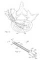
- FIG. 1is a perspective view of one embodiment of a tissue evacuation device.
- FIG. 2is a side cross-sectional view of the tissue evacuation device of FIG. 1 .
- FIG. 3is a detailed side cross-sectional view of the distal portion of the tissue evacuation device of FIG. 1 .
- FIG. 4is a detailed side cross-sectional view of the proximal portion of the tissue evacuation device of FIG. 1 .
- FIG. 5is a front cross-sectional view of the tissue evacuation device of FIG. 4 taken along line 5 - 5 .
- FIG. 6is a side view of another embodiment of a tissue evacuation device.
- FIG. 7is a side cross-sectional view of the tissue evacuation device of FIG. 6 .
- FIG. 8is a detailed side cross-sectional view of the distal portion of the tissue evacuation device of FIG. 6 .
- FIG. 9is a detailed side cross-sectional view of the proximal portion of the tissue evacuation device of FIG. 6 .
- FIG. 10is a front cross-sectional view of the tissue evacuation device of FIG. 6 taken along line 10 - 10 .
- FIG. 11is a side view of another embodiment of a tissue evacuation device.
- FIG. 12is a diagram illustrating a portion of a tissue evacuation device removing nucleus tissue.
- FIG. 13is a perspective view of another embodiment of a tissue evacuation device.
- FIG. 14is a cross-sectional view of the distal end of the tissue evacuation device of FIG. 13 taken along line 14 - 14 .
- FIG. 15is a perspective view of another embodiment of a tissue evacuation device.
- FIG. 16is a cross-sectional view of the tissue evacuation device of FIG. 15 .
- FIG. 17is a perspective, cross-sectional view of one embodiment of an assembly housing that may be used with a tissue evacuation device.
- FIG. 18is a perspective, cross-sectional view of the assembly housing of FIG. 17 taken along line 18 - 18 .
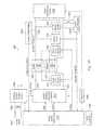
- FIG. 19is a diagram of one embodiment of a circuit that may be used to control a tissue evacuation device.
- FIG. 20is a diagram illustrating a tissue evacuation device removing nucleus tissue.
- FIG. 21is a perspective view of one embodiment of a nozzle that may be used with a tissue evacuation device.
- FIG. 22is a perspective view of another embodiment of a nozzle that may be used with a tissue evacuation device.
- FIG. 23is a perspective view of yet another embodiment of a nozzle that may be used with a tissue evacuation device.
- FIG. 24is a perspective view of still another embodiment of a nozzle that may be used with a tissue evacuation device.
- FIGS. 25A-25Bare side and top views, respectively, of an embodiment of a scraper that may be used with a tissue evacuation device.
- a tissue evacuation device 100is illustrated.
- the tissue evacuation device 100may be designed to provide a high-energy fluid (e.g., a heated vapor) to targeted tissue for breaking down the targeted tissue, such as the nucleus of an intervertebral disc. After the nucleus or other targeted tissue is broken down, the tissue evacuation device 100 may also remove some or all of the broken down tissue.
- a high-energy fluide.g., a heated vapor
- the tissue evacuation device 100may have an assembly housing 102 located on the proximal end of the device (from the perspective of a user) that may be used as a grip.
- the assembly housing 102may include one or more external connectors (i.e., fittings or couplings) for supplying power, fluid, and/or pressure to the tissue evacuation device 100 .
- such connectorsmay include a fluid connector 104 , a power (electrical) connector 106 , and a vacuum connector 108 .
- the assembly housing 102may be coupled to a collar attachment 110 that couples the assembly housing 102 to an outer tube 112 .
- the outer tube 112may serve as a device extension cannula to provide access for the high-energy fluid into tissue such as the nucleus.
- An evaporation chamber portion 114which may be separate from or integral with the outer tube 112 , may be positioned near the distal end of the outer tube 112 .
- the evaporation chamber 114is where a fluid provided to the tissue evacuation device 100 may transition from a liquid state to a high-energy vapor state.
- a nozzle 116may be located at the distal end of the outer tube 112 and may be configured to provide the high-energy vapor to the targeted tissue via one or more channels.
- the nozzle 116may include a vacuum opening for the evacuation of tissue.
- FIG. 2a cross-sectional view of the tissue evacuation device 100 of FIG. 1 is illustrated. Each portion of the tissue evacuation device is described below in greater detail, and so is not described with respect to the present figure. More specifically, the distal section (encompassing the evaporation chamber 114 and the nozzle 116 ) is described with respect to FIG. 3 and the proximal section (encompassing the assembly housing 102 and collar attachment 110 ) is described with respect to FIG. 4 .
- the distal section of FIG. 2is enlarged to illustrate a cross-sectional view of the outer tube 112 , evaporation chamber 114 , and nozzle 116 in greater detail.
- the outer tubemay be formed at least partially of an electrically conductive material (e.g., a metal).
- the conductive material of the outer tube 112may be relatively thin from the assembly housing 102 until it nears the distal portion of the outer tube 112 where the evaporation chamber 114 is located. At this point, the conductive material may be thicker to form an electrode 307 .
- the conductive material forming the outer tube 112may be a single thickness throughout and/or may connect to an electrode (e.g., the electrode 307 ) that is not formed from the outer tube 112 . It is understood that, in some embodiments, the outer tube 112 may contain no conductive material and other means (e.g., a wire integrated into or running along the outer tube) may be used for transferring voltage to the distal end of the tissue evacuation device 100 .
- other meanse.g., a wire integrated into or running along the outer tube
- An inner tube 302may be positioned within the outer tube 112 .
- the exterior of the inner tube 302may be approximately equidistant from the interior of the outer tube 112 (e.g., the inner and outer tubes are concentric circles), but other configurations may be used.
- the inner tube 302may also be formed at least partially from a conductive material.
- the interior of the inner tube 302may be substantially hollow and may provide a path for a vacuum between the distal end of the tissue evacuation device 100 and the assembly housing 102 .
- An outer electrode wire 304may connect the outer tube 112 (or the conductive portion of the outer tube) to a power source.
- Insulation material 308may be positioned between the inner tube 302 and outer tube 112 for at least a portion of the length of each tube, and may stop at approximately the evaporation chamber 114 .
- the insulation material 308may minimize or prevent electrical current from moving between the electrodes formed by the outer tube 112 and inner tube 302 when voltage is applied to the outer electrode wire 304 and an inner electrode wire 407 ( FIG. 4 ).
- One or more fluid spaces 310may be provided within the evaporation chamber 114 .
- the fluid space 310may be connected to the fluid connector 106 of the assembly housing 102 via a channel or conduit 312 positioned between the inner tube 302 and outer tube 112 . It is understood that the conduit 312 may form part of the fluid space 310 or may be separated from the fluid space (e.g., by a valve or other fluid control means).
- a porous material 314may be positioned proximate to the conductive material of the inner tube 302 and outer tube 112 . It is noted that the insulation material 308 may be positioned so as not to insulate the area covered by the porous material 314 .
- the porous material 314which may be a ceramic open-cell porous material, may be positioned within or coupled to the fluid space 310 and may serve as a capillary fluid container. Accordingly, fluid from the fluid space 310 may enter the porous material 314 .
- the porous material 314may be selected to accommodate various requirements, such as reducing arcing that may occur between the inner tube 302 and outer tube 112 when voltage is applied.
- the nozzle 116may include one or more vapor conduits 316 coupling the evaporation chamber (e.g., the porous material 314 ) with one or more nozzle holes 318 .
- the particular configuration of the nozzle 116may vary.
- a single vapor conduit 316may be coupled to multiple nozzle holes 318
- multiple vapor conduitsmay be coupled to a single nozzle hole, or there may be a one to one correspondence between the vapor conduits and the nozzle holes.
- evaporation chamberand “nozzle” are for purposes of illustration through the present disclosure and are not meant to limit the present disclosure by requiring that certain components be positioned within a particular section. For example, some overlap may occur between the evaporation chamber and the nozzle and such overlap may depend largely on the particular embodiment of the tissue extraction instrument.
- the proximal section of FIG. 2is enlarged to illustrate a cross-sectional view of the assembly housing 102 and collar attachment 110 in greater detail.
- the assembly housing 102may include the fluid connector 104 , the electrical connector 106 , and the vacuum connector 108 .
- the outer tube 112may enter and be supported by the collar attachment 110 but may not extend into the assembly housing 102 , while the inner tube 302 may extend through at least a portion of the assembly housing 102 .
- An o-ring 402may provide a seal between the collar attachment 110 and the outer tube 112 .
- a shoulder 404may provide an attachment flange for outer tube 112 .
- the shoulder 404may have a fitting that couples to outer tube 112 or the shoulder 404 may be welded to outer tube 112 and then attached to collar attachment 110 .
- the collarmay be removable and, in some embodiments, may contain fastening mechanisms that allow for the attachment and detachment of the outer tube 112 and/or other components.
- the fluid connector 104may couple an external fluid source 105 (as shown in FIG. 2 ) to the fluid space 310 via a valve 405 and the conduit 312 ( FIG. 3 ).
- the fluidmay be supplied as a liquid to the fluid space 310 and converted to a gas in the evaporation chamber 114 .
- the fluid connector 104may include a tailored (e.g., barbed) fitting for connection.
- the electrical connector 106may provide power for a bipolar electrode set (positive and negative electrodes) formed from outer tube 112 and inner tube 302 . More specifically, the electrical connector 106 may couple the outer electrode wire 304 to a power source to provide power to the outer tube 112 . In the present embodiment, the outer electrode wire 304 may connect directly to the proximal end of the outer tube 112 . The electrical connector 106 may also couple an inner electrode wire 407 to the power source to provide power to the inner tube 302 . In the present embodiment, the inner electrode wire 407 may connect to a collar 406 that is coupled to the inner tube 302 . The collar 406 may be conductive or may contain conductive elements that transfer voltage from the inner electrode wire 407 to the inner tube 302 .
- the inner electrode wire 407may be coupled directly to the inner tube 302 .
- Various wire fasteners/guidessuch as a wire retainer 408 used for outer electrode wire 304 , may be used to seal and/or support one or both of the inner and outer electrode wires.
- the vacuum connector 108may be coupled to the proximal end of the inner tube 302 .
- An o-ring 410may provide a seal between inner tube 302 and assembly housing 102 .
- An o-ring 412may provide a seal between inner tube 302 and collar attachment 110 .
- the vacuum connector 108may include a tailored fitting (e.g., a barb) for connection to a vacuum system such as a surgical room suction system.
- tissue extraction device 100may include various modifications.
- outer electrode wire 304 and inner electrode wire 407are illustrated as connected (e.g., soldered or otherwise affixed) within the tissue extraction device 100 , various means may be supplied to enable a user to engage and/or disengage a wire.
- FIG. 5a cross-sectional view of the assembly housing 102 of FIG. 5 along line 5 - 5 of FIG. 4 is illustrated.
- the fluid connector 104 and electrical connector 106 of housing assembly 102are visible.
- a tissue evacuation device 600may include an assembly housing 602 located on the proximal end of the device (from the perspective of a user) that may be used as a grip.
- the assembly housing 602which will be discussed in greater detail with respect to FIG. 9 , may include one or more external connectors or fittings for supplying power, fluid, and/or pressure to the tissue evacuation device 600 .
- such connectorsmay include a fluid connector 604 , a power (electrical) connector 606 , and a vacuum connector 608 .
- the assembly housing 602may be coupled to a collar attachment 610 that couples the assembly housing 602 to an outer tube 612 .
- the outer tube 612may provide a relatively rigid structure coupled to (or including) an evaporation chamber 614 and a nozzle 616 .
- the outer tube 612 in the present embodimentmay not be included in a power circuit used to evaporate fluid.
- the evaporation chamber 614may be where a fluid provided to the tissue evacuation device 600 may transition from a liquid state to a high-energy vapor state.
- the nozzle 616may be located at the distal end of the outer tube 612 and may be configured to provide the high-energy vapor to the targeted tissue via one or more channels. In the present example, the nozzle 616 may include a vacuum opening for the evacuation of tissue.
- FIG. 7a cross-sectional view of the tissue evacuation device 600 of FIG. 6 is illustrated. Each portion of the tissue evacuation device is described below in greater detail, and so is not described with respect to the present figure. More specifically, the distal section (encompassing the evaporation chamber 614 and the nozzle 616 ) is described with respect to FIG. 8 and the proximal section (encompassing the assembly housing 602 and collar attachment 610 ) is described with respect to FIG. 9 .
- the distal section of FIG. 7is enlarged to illustrate a cross-sectional view of the outer tube 612 , evaporation chamber 614 , and nozzle 616 in greater detail.
- the outer tubemay provide an exterior structure but may not form part of the electrical circuit and, accordingly, may not be formed of an electrically conductive material (e.g., a metal).
- the outer tube 112may vary in thickness or may be of a uniform thickness. It is understood that, in some embodiments, the outer tube 112 may include conductive material and be used to form part of an electrical circuit.
- An inner tube 802may be positioned within the outer tube 612 .
- the exterior of the inner tube 802may be approximately equidistant from the interior of the outer tube 612 (e.g., the inner and outer tubes are concentric circles), but other configurations may be used.
- the inner tube 802may be formed at least partially from a conductive material and may form an inner electrode that is part of an electrical circuit.
- the interior of the inner tube 802may be substantially hollow and may provide a path for a vacuum between the distal end of the tissue evacuation device 600 and the assembly housing 602 .
- An outer electrode 804may be electrically coupled to the assembly housing 602 by an outer electrode wire 806 .
- the outer electrode wire 806may be positioned between the outer tube 612 and the inner tube 802 .
- Insulation material 808may be used to cover the exterior of the outer electrode 804 .
- the outer tube 612may extend over the outer electrode 804 and the insulation material 808 may be positioned between the outer electrode and the outer tube. In other embodiments, if the outer tube 612 extends over the outer electrode 804 and is not conductive, the insulation material 808 may not be present.
- Insulation material 810e.g., a Teflon sleeve
- the insulation material 810may be used to electrically insulate the inner tube 802 from the outer electrode wire 806 and outer tube 612 .
- One or more fluid spaces 812may be provided within the evaporation chamber 614 .
- the fluid space 812may be connected to the fluid connector 604 of the assembly housing 602 via a channel or conduit 814 positioned between the inner tube 802 and outer tube 612 . It is understood that the conduit 812 may form part of the fluid space 810 or may be separated from the fluid space (e.g., by a valve or other fluid control means).
- a porous material 816may be positioned between the conductive material of the inner tube 802 and outer electrode 804 . It is noted that the insulation material 810 may be positioned so as not to insulate the area covered by the porous material.
- the porous material 816which may be a ceramic open-cell porous material, may be positioned within or coupled to the fluid space 812 and may serve as a capillary fluid container. Accordingly, fluid from the fluid space 812 may enter the porous material 816 .
- the porous material 816may be selected to accommodate various requirements, such as reducing arcing that may occur between the inner tube 802 and electrode 804 when voltage is applied.
- the nozzle 616may include one or more vapor conduits 818 coupling the evaporation chamber (e.g., the porous material 816 ) with one or more nozzle holes 820 .
- the particular configuration of the nozzle 616may vary. For example, a single vapor conduit 818 may be coupled to multiple nozzle holes 820 , multiple vapor conduits may be coupled to a single nozzle hole, or there may be a one to one correspondence between the vapor conduits and the nozzle holes.
- the proximal section of FIG. 7is enlarged to illustrate a cross-sectional view of the assembly housing 602 and collar attachment 610 in greater detail.
- the assembly housing 602may include the fluid connector 604 , the electrical connector 606 , and the vacuum connector 608 .
- the outer tube 612may enter and be supported by the collar attachment 610 but may not extend into the assembly housing 602 , while the inner tube 802 may extend through at least a portion of the assembly housing 602 .
- An o-ring 902may provide a seal between the collar attachment 610 and the outer tube 612 .
- a shoulder 904may provide an attachment flange for outer tube 612 .
- the shoulder 904may have a fitting that couples to outer tube 612 or the shoulder 904 may be welded to outer tube 612 and then attached to collar attachment 610 .
- the fluid connector 604may couple an external fluid source (not shown) to the fluid space 812 via a valve 905 and the conduit 814 ( FIG. 8 ).
- the fluidmay be supplied as a liquid to the fluid space 812 and converted to a gas in the evaporation chamber 614 .
- the fluid connector 604may include a tailored (e.g., barbed) fitting for connection.
- the electrical connector 606may provide power for a bipolar electrode set (positive and negative electrodes) formed from electrode 804 and inner tube 802 . More specifically, the electrical connector 606 may couple the outer electrode wire 806 to a power source to provide power to the electrode 804 . In the present embodiment, the outer electrode wire 806 may connect directly to electrode 804 . The electrical connector 606 may also couple an inner electrode wire 907 to the power source to provide power to the inner tube 802 . In the present embodiment, the inner electrode wire 907 may connect to a collar 906 that is coupled to the inner tube 802 . The collar 906 may be conductive or may contain conductive elements that transfer voltage from the inner electrode wire 907 to the inner tube 802 .
- the inner electrode wire 907may be coupled directly to the inner tube 802 .
- Various wire fasteners/guidessuch as a wire retainer 908 used for outer electrode wire 806 , may be used to seal and/or support one or both of the inner and outer electrode wires.
- the vacuum connector 608may be coupled to the proximal end of the inner tube 802 .
- An o-ring 910may provide a seal between inner tube 802 and assembly housing 602 .
- An o-ring 912may provide a seal between inner tube 802 and collar attachment 610 .
- the vacuum connector 608may include a tailored fitting (e.g., a barb) for connection to a vacuum system such as a surgical room suction system.
- tissue extraction device 600may include various modifications.
- the outer electrode wire 806 and inner electrode wire 907are illustrated as connected (e.g., soldered or otherwise affixed) within the tissue extraction device 600 , various means may be supplied to enable a user to engage and/or disengage a wire.
- FIG. 10a cross-sectional view of the assembly housing 602 of FIG. 6 along lines 10 - 10 is illustrated.
- a tissue evacuation device 1100may include an assembly housing 1102 located on the proximal end of the device (from the perspective of a user) that may be used as a grip.
- the assembly housing 1102may include one or more external connectors or fittings for supplying power, fluid, and/or pressure to the tissue evacuation device 1100 .
- such connectorsmay include a fluid connector 1104 , a power (electrical) connector 1106 , and a vacuum connector 1108 .
- the assembly housing 1102may be coupled to a tube 1110 via a collar 1112 .
- the tube 1110may extend from the assembly housing 1102 to an evaporation chamber 1114 .
- a nozzle 1116may be used to direct heated vapor from the evaporation chamber 1114 to a surgical site and may contain a vacuum opening coupled to the vacuum connector 1108 .
- the tube 1110may contain other components, such as an inner tube described with respect to other embodiments.
- the evaporation chamber 1114may be structured as has been described or may be constructed differently.
- the tube 1110may be curved.
- the curvemay be fixed or the tube 1110 may be articulating. Accordingly, a surgeon may control the movement of the tube 1110 .
- the surgeonmay move the tube 1110 side to side or forward and backward to access the targeted tissue, as illustrated in FIG. 12 .
- a picture representation of a curved tubeillustrates the removal of nucleus tissue 1200 from a spinal disc 1202 .
- the tube 1110may provide access to nucleus tissue 1200 for a nuclectomy.
- the tube 1110may be inserted through the annulus to the nucleus tissue 1200 .
- the tissue evacuation device 1100may then break down the nucleus tissue 1200 using a heated vapor and remove at least a portion of the resulting debris from the spinal disc 1202 . It is understood that, while FIG. 11 illustrates the tissue evacuation device 1100 removing nucleus tissue 1200 , the tissue evacuation device 1100 may be used to remove other types of tissue.
- a tissue evacuation device 1300may include an assembly housing 1302 located on the proximal end of the device (from the perspective of a user) that may be used as a grip.
- the assembly housing 1302may include one or more external connectors or fittings for supplying power, fluid, and/or pressure to the tissue evacuation device 1300 .
- such connectorsmay include a fluid connector 1304 , a power (electrical) connector 1306 , and a vacuum connector 1308 .
- the assembly housing 1302may be coupled to an outer tube 1310 that extends from the assembly housing to a nozzle 13 12 .
- the outer tube 1310may contain an inner tube 1314 that provides support for a heating element 1316 .
- the power connector 1306may provide a connection to an energy source (e.g., a variable impedance output RF generator such as that shown in FIG. 19 ) that may be used to provide the energy needed to move a fluid supplied via the fluid connector 1304 from a liquid state to a vapor state.
- the vacuum connector 1308may be used to provide a negative pressure within the inner tube 1314 for removing small fragments of debris and droplets of condensed fluid (e.g., saline).
- the fluid connector 1304may provide a fluid, such as water or saline solution, to the assembly housing 1302 .
- the fluid connector 1304may be configured to enable a user to control the inflow of the saline solution or other fluid into the assembly housing 1300 .
- the outer tube 1310may surround the inner tube 1314 .
- the heating element 1316may be a single wire that is wrapped around the inner tube 1314 .
- the heating element 1316may be used to heat the fluid to varying temperatures based upon the voltage applied to the heating element. In other embodiments, multiple wires may be used.
- the wire or wiresmay be arranged differently (e.g., longitudinally down the length of the inner tube 1314 or each wire may be wrapped only partially around the inner tube).
- the heating element 1316may be supported by the outer tube 1310 rather than the inner tube 1314 , or may be supported by both the outer and inner tubes.
- a space 1400may exist between the outer tube 1310 and inner tube 1314 to allow fluid to pass from the assembly housing 1302 to the nozzle 1312 .
- the fluidmay vaporize and be discharged as vapor from the nozzle 1312 via nozzle ports 1402 .
- a vacuum port 1404 in the nozzle 1312may be coupled to the inner tube 1314 to couple the vacuum pressure supplied by the inner tube with the surgical site. Accordingly, when the nozzle 1312 is placed within the nucleus, the high temperature vapor may escape through the steam ports 1402 and break up the nucleus tissue, and debris and fluid may be removed from the nucleus via the vacuum port 1404 .
- this tissue extraction device 1300may be envisioned.
- an additional tube(not shown) may be provided between the outer tube 1310 and the inner tube 1314 .
- This additional tubemay be used to separate the heating element 1316 from the fluid that is to be vaporized. Heating of the additional tube by the heating element 1314 may then vaporize the fluid.
- multiple tubes(not shown) that extend at least part of the distance from the assembly housing 1302 to the nozzle 1312 may be positioned between the outer tube 1310 and inner tube 1314 . Each tube may serve as a fluid conduit and the fluid may be vaporized by the heating element 1316 .
- each tubemay be associated with a particular nozzle port 1402 , which may provide for additional user control of the nozzle ports and/or amount of heated vapor used during a surgical procedure.
- a tissue evacuation device 1500may include an assembly housing 1502 located on the proximal end of the device (from the perspective of a user) that may be used as a grip.
- the assembly housing 1502may include one or more external connectors or fittings for supplying power, fluid, and/or pressure to the tissue evacuation device 1500 .
- such connectorsmay include a fluid connector 1504 , a power (electrical) connector 1506 , a vacuum connector 1508 , and a CO 2 connector 1510 .
- the assembly housing 1502may be coupled to an outer tube 1512 that extends from the assembly housing to a nozzle 1514 .
- the vacuum connector 1508may be the proximal end of an inner tube that is surrounded by the outer tube 1512 between the assembly housing 1502 and the nozzle 1514 .
- the power connector 1506may provide a connection to an energy source (e.g., a variable impedance output RF generator such as that shown in FIG. 19 ) that may be used to provide the energy needed to move a fluid supplied via the fluid connector 1504 from a liquid state to a vapor state.
- the vacuum connector and corresponding inner tube 1508may be used to provide a negative pressure for removing small fragments of debris and droplets of condensed fluid (e.g., saline).
- the fluid connector 1504may provide a fluid, such as water or saline solution, to the assembly housing 1502 .
- the CO 2 connectormay be coupled to a CO 2 tube ( FIG. 16 ) that may be used to provide CO 2 gas for cooling the temperature of the vapor in the main tube 1512 . It is understood that the use of CO 2 is for purposes of example and that other suitable fluids may be used in place of or in conjunction with CO 2 .
- the outer tube 1512may surround the inner tube 1508 and a CO 2 tube 1600 that is positioned between the outer and inner tubes.
- the outer tube 1512 , CO 2 tube 1600 , and inner tube 1508may be concentric cylinders.
- One or more heating elementsmay be positioned between the assembly housing 1502 and the nozzle 1514 in the space between the outer tube 1512 and CO 2 tube 1600 and/or the space between the CO2 tube and the inner tube 1508 .
- One or more o-rings, such as an o-ring 1602may be used to provide a seal between components such as the inner tube 1508 and the CO 2 tube 1600 .
- connections between the various connectors and the spaces between the outer tube 1512 and CO 2 tube 1600 and between the CO 2 tube and the inner tube 1508may vary, as may the location of the heating element(s).
- the fluid connector 1504may supply fluid to the space between the outer tube 1512 and the CO 2 tube 1600
- the CO 2 connector 1506may supply CO 2 to the space between the CO 2 tube and the inner tube 1308 .
- the heating elementmay be positioned in the space between the inner tube 1508 and the CO 2 tube 1600 or between the outer tube 1512 and the CO 2 tube 1600 .
- the fluid connector 1504may supply fluid to the space between the inner tube 1508 and the CO 2 tube 1600
- the CO 2 connector 1506may supply CO 2 to the space between the CO 2 tube and the outer tube 1512
- the heating elementmay be positioned in the space between the inner tube 1508 and the CO 2 tube 1600 or between the outer tube 1512 and the CO 2 tube 1600 .
- a fluid such as CO 2 gasmay be provided in the same cylindrical space as the heated vapor.
- the CO 2 gasmay be injected into the space 1400 between the outer tube 1310 and inner tube 1314 .
- an assembly housing 1700is illustrated.
- the assembly housing 1700may be configured for use with a tissue evacuation device such as those illustrated in FIGS. 13 and 15 .
- the assembly housing 1700may be used to control the fluid (e.g., water) pressure and the CO 2 pressure in a tissue evacuation device. It is understood that the assembly housing 1700 may be connected to an energy source and controller to control the fluid intake and pressure and the CO 2 intake and pressure.
- the water in the assembly housing 1700may provided through a water port 1702 .
- a water pressure gauge port 1704may be used to measure the water pressure.
- a water cap 1706may retain a water piston 1708 in the assembly housing 1700 .
- a regulator piston 1710 and a water regulator spring 1712may further assist with water pressure regulation.
- a water pressure regulator screw 1714 and two plugs 1716 a and 1716 bmay be used to hold the regulator piston 1710 and the water regulator spring 1712 in place.
- the water regulator screw 1714may enable the water pressure to be adjusted manually.
- CO 2 in the assembly housing 1700may be provided through a CO 2 port 1718 .
- a CO 2 pressure gauge port 1720may be used to measure the CO 2 pressure.
- a CO 2 regulator piston 1722 and a CO 2 regulator spring 1724may assist with the CO 2 pressure regulation.
- a CO 2 pressure regulator screw 1726 and a plug 1728may hold the CO 2 regulator piston 1722 and the CO 2 regulator spring 1724 in place.
- the CO 2 pressure regulator screw 1726may enable the CO 2 pressure to be adjusted manually.
- a cartridge puncture screw 1730may be used to control the CO 2 released from a CO 2 cartridge ( FIG. 16 ).
- a CO 2 cap 1732may be used in conjunction with the CO 2 regulator piston 1722 and the CO 2 regulator spring 1724 to control the CO 2 pressure.
- a water piston cap screw 1800may be used to control the water piston 1708 and the corresponding water pressure.
- a CO 2 cartridge 1802may be used to provide CO 2 to the assembly housing 1700 and the CO 2 port 1718 may be used to provide additional CO 2 beyond what is available in CO 2 cartridge 1802 .
- the CO 2 cartridge 1802may not be implemented.
- the assembly housing 1700may be used to control the water pressure and CO 2 pressure for a tissue evacuation device.
- the assembly housing 1700may be used to control the water or saline solution pressure in the main tube 1310 .
- the water piston 1708 , regulator piston 1710 , and the regulator spring 1712may work in conjunction to control the water pressure.
- the assembly housing 1700may also be used with the tissue evacuation device 1300 to control the injection of CO 2 into the main tube 13 10 .
- the CO 2 gas and the steammay occupy the space 1400 ( FIG. 14 ).
- the CO 2may be used to cool the heated saline vapor.
- the CO 2 cap 1732 , CO 2 regulator piston 1722 , CO 2 regulator spring 1724 , and the CO 2 cartridge 1802may work in conjunction to control the CO 2 pressure.
- a vacuum tube(not shown) may be positioned within or coupled to the assembly housing 1700 .
- the vacuum tubemay reside within the assembly housing 1700 or outside of the assembly housing 1700 .
- one or more heating elements(not shown) may be positioned within the assembly housing 1700 .
- a heating elementmay heat the water or other fluid inside the assembly housing 1700 or outside of the assembly housing 1700 .
- variable impedance output RF circuit 1900may be used as an energy source for a tissue evacuation device to vaporize a fluid such as water or saline solution. It is understood that a tissue evacuation device is not limited to the energy source provided by the variable impedance output RF circuit 1900 , and that the circuit 1900 is only provided as an illustration of one possible energy source.
- the circuit 1900may be coupled to a tissue evacuation device 1940 (e.g., to the assembly housing of such a device).
- the tissue evacuation devicemay be similar to those described previously (e.g., the tissue evacuation device 1300 of FIG. 13 ).
- various embodiments of a tissue evacuation devicemay convert a fluid to a heated vapor state.
- the circuit 1900illustrates one embodiment of a circuit that may be used to supply and control the energy used to create the heated vapor.
- a user interface 1908may be used by a user to program a digital signal processor (DSP) 1910 to desired specifications (e.g., pressure, temperature, flow rate, and duration).
- the DSP 1910may control, monitor, and measure one or more variables within the circuit 1900 and/or the tissue evacuation device 1940 .
- An AC input voltage 1902may supply a primary set of coils of a transformer 1904 .
- a secondary set of coils of the transformer 1904may be connected to a variable output power supply 1906 .
- the variable output power supply 506may convert the AC input voltage 1902 into a variable DC voltage.
- the DSP 1910may control the variable output power supply 1906 to produce a specific DC voltage. In the present embodiment, the voltage ranges from approximately ten volts to approximately 160 volts DC.
- the DC voltagemay be applied to power steering switches (e.g., an H bridge) 1912 .
- This DC voltagemay control the amplitude of the output power.
- the power steering switches 1912may form an inverter circuit to convert a DC voltage input into a RF AC output.
- the DSP 1910may supply the power steering switches 1912 with a pulse width modulated (“PWM”) signal and an enable signal.
- PWMpulse width modulated
- the PWM signalmay provide the frequency of the RF AC output and the enable signal may turn the power steering switches 1912 on and off.
- the power steering switches 1912may supply voltage to two transformers 1920 and 1922 .
- Capacitors 1916 and 1918may be connected to the primary windings of transformer 1920 and transformer 1922 , respectively.
- a solid state switch 1914may be connected to the primary of coils of transformer 1922
- another solid state switch 1924may be connected to the secondary set of coils of transformer 1922 .
- An enable signal from the DSP 1910may turn the solid state switches 1914 and 1924 on and off.
- the transformers 1920 and 1922may be used to drive various impedance loads.
- transformer 1920may have a low value windings ratio (e.g., 1:1) that may drive a low impedance load.
- Transformer 1922may have a higher value windings ratio (e.g., 1:X) that may effectively develop a higher output voltage to drive a relatively high impedance load.
- An output filter 1926may filter the output of the transformers 1920 and 1922 to provide a relatively precise AC output.
- An active energy clamp 1928may limit output power on detection of a voltage spike to prevent high voltages at the tissue evacuation device 1940 .
- the RF AC outputmay be supplied to the tissue evacuation device 1940 to heat the pressurized fluid (e.g., water or saline solution).
- a fluid pump 1938may supply the water or saline solution to the tissue evacuation device 1940 at a controlled rate.
- the DSP 1910may control the liquid leaving the fluid pump 1938 .
- a signal conditioning block 1930 and a current transformer 1932may provide the output current of the transformers 1920 and 1922 to the DSP 1910 .
- a signal conditioning block 1934 and a transformer 1936may provide the output voltage of the transformers 1920 and 1922 to the DSP 1910 . These two mechanisms may provide a current feedback and a voltage feedback, respectively. This enables the DSP 1910 to read the output currents and voltages and adjust the variables of the RF generator circuit 1900 accordingly.
- the low impedance transformer 1920may always be in the circuit and the high impedance transformer 1922 may be either in series with the first transformer 1920 or may be effectively shorted out of the circuit by the solid state switches 1914 , 1924 .
- the DSP 1910may control the solid state switches 1914 , 1924 .
- the circuit 1900may have the capability to drive the initial low impedance load (transformer 1920 ) effectively with the high impedance load (transformer 1922 ) removed from the circuit. Then, at an appropriate time, the high impedance output transformer 1922 may be switched into the circuit, which may allow efficient energy transfer to the high impedance load.
- two separate magnetic pathsmay be provided for the different windings to prevent unnecessary high circulating currents in the windings of the transformer 1922 .
- the state of the processmay be estimated by calculating the electrical impedance of the load.
- the circuit 1900may have the capability to monitor input voltage, output current, and output voltage through the DSP 1910 . These parameters may be utilized to calculate the process state and determine the proper settings for power input, fluid flow rate, and output impedance.
- the desired process statemay be input by a user via the user interface 1908 .
- Such monitor mechanismsmay be electrically insulated from the high voltage output to allow a patient safe isolated output.
- a diagram 2000illustrates a tissue evacuation device (e.g., the tissue evacuation device 1500 of FIG. 15 ) removing nucleus tissue 2006 .
- the tissue evacuation device 1500may be inserted into an intervertebral disc 2002 that resides between a vertebra 2004 and another vertebra (not shown) in the human spine.
- the intervertebral disc 2002may include nucleus tissue 2006 surrounded by annulus tissue 2008 .
- the nucleus tissue 2006may have a lower collagen content than the surrounding annulus tissue 2008 , and may be broken up with less energy than the annulus.
- a nozzle 1314may be placed proximate to the nucleus tissue 2006 .
- a heated vaporsuch as steam having a proper temperature and pressure may be directed into the nucleus tissue 2006 through steam ports (not shown) in the nozzle 1314 .
- a vacuummay then be applied through the nozzle 1314 to remove at least a portion of the vaporized nucleus tissue and the condensed fluid from the steam.
- the temperature and pressure of the steamis selected to have minimal impact on the annulus 2008 .
- a circuitsuch as the variable impedance output RF generator circuit 1900 of FIG. 19 , may be used to adjust the temperature and pressure of the steam to remain within the desired range.
- the nozzle 2100may include a first set of ports 2102 proximal to the end of the nozzle and at least a second set of ports 2104 positioned further back in the nozzle from the first set of ports.
- the first and second port sets 2102 and 2104may be separated by a linear distance.
- a third set of ports 2106may also be provided.
- Each set of ports 2102 , 2104 , and 2106may be positioned around the axis of a tube. While the present embodiment illustrates the ports of each set 2102 , 2104 , and 106 as being evenly distributed around the axis, it is understood that such a distribution is not necessary and the sets of ports, or even individual ports, may be distributed in many different ways.
- the second and third sets of ports 2104 and 2106may aid in minimizing or preventing the nozzle 2100 from becoming clogged during a surgical procedure.
- the nozzle 2100may become clogged as debris is vacuumed back to the assembly housing.
- the nozzle sets 2104 and 2106may serve to further break down the debris as it passes through the nozzle and into the vacuum tube, which may minimize or prevent such clogging.
- the different sets of ports 2102 , 2104 , and 2106may be coupled to different vapor conduits (e.g., the vapor conduits 316 of FIG. 3 ). Accordingly, the particular configuration of the ports sets 2102 , 2104 , and 2106 may vary. For example, a single vapor conduit 316 may be coupled to multiple ports, multiple vapor conduits may be coupled to a single port, or there may be a one to one correspondence between the vapor conduits and the ports. Furthermore, vapor conduits may be shared among sets of ports. In addition, the division of ports into sets as shown is for purposes of illustration only, and ports may be individually placed in many different patterns.
- a nozzle 2200is illustrated that may be used with a tissue evacuation device, such as the tissue evacuation device 1300 of FIG. 13 .
- the nozzle 2200may include ports 2202 that may be positioned around the axis of a tube.
- a front surface 2204 of the nozzle 2200may include an opening or bore 2206 and an inner portion 2208 extending outwardly from the bore.
- the inner portion 2208 or the entire front surface 2204may be conical.
- the bore 2206may be coupled to a vacuum source (not shown) and the ports 2202 may be coupled to a source (not shown) for steam or another heated gas.
- each port 2202may be a slot that curves in a spiral manner from an inner diameter of the inner portion 2208 (e.g., near the bore 2206 ) towards an outer diameter that is farther from the bore.
- the spiral designmay, for example, concentrate the force provided by the heated gas. While the present embodiment illustrates the ports 2202 as being evenly distributed around the bore 2206 , it is understood that other distributions may be used.
- the nozzle 2200 of FIG. 22is illustrated with a plurality of bristles or other extensions 2300 that may be used, for example, to scrape or dislodge tissue from an annulus. It is understood that the shape, height, and width of the bristles 2300 , as well as the number of bristles, may be modified. Furthermore, the bristles 2300 may be rigid or somewhat flexible.
- a nozzle 2400may be used with a tissue evacuation device, such as the tissue evacuation device 1300 of FIG. 13 .
- the nozzle 2400may include front ports 2402 and side ports 2404 that may be positioned around the axis of a tube 2406 , such as the outer tube 1310 of FIG. 13 .
- both the front ports 2402 and side ports 2404may be coupled to a source (not shown) for steam or another heated gas, some or all of the front ports 2402 or side ports 2404 may be coupled to a vacuum source (not shown).
- an inner housing 2408may be coupled to a vacuum source or a heated gas source, while the front ports 2402 and side ports 2404 (positioned in an outer housing 2410 ) may be coupled to the source not coupled to the inner housing 2408 .
- Slots or apertures 2412 in the inner housing 2408may provide access for the vacuum or heated gas.
- a scraper 2500may be used with a tissue evacuation device, such as the tissue evacuation device 1300 of FIG. 13 .
- the scraper 2500may be coupled to a distal end of the tissue evacuation device 1300 .
- the scraper 2500may include one or more cutting edges 2502 positioned on a proximal portion 2504 and a distal portion 2506 . Movement of the proximal portion 2504 and distal portion 2506 relative to one another may be achieved by one or more actuators 2508 . Such movement may be used to remove tissue.
- a tissue evacuation devicemay include a surgical instrument having electrodes in a distal end of the instrument, such as:
- a surgical instrumentcomprising:
- an outer tubehaving a first proximal end coupled to the housing and a first distal end;
- an inner tubehaving a second proximal end and a second distal end, wherein the inner tube is positioned within the outer tube and the second proximal end is coupled to the housing;
- a nozzlecoupled to at least one of the first and second distal ends
- first and second electrodespositioned opposite one another towards the first distal end between the nozzle and the first proximal end, wherein the first and second electrodes are separated by a porous material;
- a liquid spacepositioned between the outer and inner tubes and coupled to the porous material and a liquid source.
- the surgical instrument of embodiment 7further comprising an insulation material covering an exterior surface of the outer tube.
- the surgical instrument of embodiment 10further comprising an insulation material positioned between the outer and inner tubes, wherein the insulation material is not present between the outer and inner tubes at a location of the first and second electrodes.
- a surgical instrumentcomprising:
- a first tubehaving a first proximal end coupled to the housing and a first distal end, wherein at least a portion of the first tube is electrically conductive and forms a first electrode;
- a second tubehaving a second proximal end and a second distal end, wherein the inner tube is positioned within the outer tube and the second proximal end is coupled to the housing, and wherein at least a portion of the second tube is electrically conductive and forms a second electrode positioned opposite the first electrode;
- a vaporization chamberformed of a porous material and positioned at least partially between the first and second electrodes and coupled to a gas conduit leading to a nozzle on the second distal end;
- a liquid conduitconfigured to transport a liquid to the vaporization chamber.
- the surgical instrument of embodiment 14further comprising an insulation material positioned between the first and second tubes except for an area of the first and second tubes forming the first and second electrodes, respectively.
- a conductive collarcoupled to the second proximal end
- a tissue evacuation devicemay include a surgical instrument having a heating element along a tube, such as:
- a surgical instrumentcomprising:
- a first tubehaving a first proximal end coupled to the housing and a first distal end;
- a second tubehaving a second proximal end and a second distal end, wherein the second tube is positioned within the first tube and the second proximal end is coupled to the housing;
- heating elementpositioned between the first and second tubes, wherein the heating element extends at least partially between the first proximal end and the first distal end;
- fluid conduitformed between the first and second tubes, wherein at least a portion of the fluid conduit is proximate to the heating element so that liquid within the fluid conduit can be vaporized.
- the surgical instrument of embodiment 1further comprising a nozzle coupled to the distal end of at least one of the first and second tubes, wherein the nozzle includes at least one exhaust port coupled to the fluid conduit.
- the surgical instrument of embodiment 1further comprising a third tube positioned between the first and second tubes.
- liquid portcoupled to the fluid conduit, wherein the liquid port connects the fluid conduit to a liquid source
- a liquid regulator mechanismto regulate liquid flow into the fluid conduit.
- a gas portcoupled to a gas conduit positioned between the first and second tubes, wherein the gas port connects the gas conduit to a gas source;
- a gas regulator mechanismto regulate gas flow into the gas conduit.
- the surgical instrument of embodiment 15further comprising a third tube positioned between the first and second tubes.
- a surgical instrumentcomprising:
- a first tubehaving a first proximal end coupled to the housing and a first distal end;
- a second tubehaving a second proximal end and a second distal end, wherein the second tube is positioned within the first tube and the second proximal end is coupled to the housing;
- heating elementpositioned between the first and second tubes, wherein the heating element extends at least partially between the first proximal end and the first distal end;
- a fluid conduitpositioned within the first tube, wherein at least a portion of the fluid conduit is proximate to the heating element so that fluid within the fluid conduit can be vaporized.
- the surgical instrument of embodiment 21further comprising a third tube positioned within the first tube, wherein the fluid conduit is divided between the second and third tubes.
- An attachment for a surgical instrumentcomprising:
- a distal portionhaving at least a first cutting edge on a proximal surface thereof
- a proximal portionconfigured for coupling to the surgical instrument, wherein a distal surface of the proximal portion includes a second cutting edge positioned to contact the first cutting edge when the distal and proximal portions are in contact;
- the spacingincludes a maximum distance and a minimum distance between the distal and proximal portions, and wherein the first and second portions are abutting at the minimum distance.
- the present inventioncan take many forms and embodiments. Accordingly, several variations of the present design may be made without departing from the scope of the invention.
- the capabilities outlined hereinallow for the possibility of a variety of models. This disclosure should not be read as preferring any particular model, but is instead directed to the underlying concepts on which these models can be built.
- circular tubesare illustrated in the present disclosure, the tubes discussed in the present disclosure may be any shape.
- components described with respect to one embodimentmay be used in place of or in addition to components described with respect to another embodiment.
Landscapes
- Health & Medical Sciences (AREA)
- Surgery (AREA)
- Engineering & Computer Science (AREA)
- Life Sciences & Earth Sciences (AREA)
- Biomedical Technology (AREA)
- Otolaryngology (AREA)
- Nuclear Medicine, Radiotherapy & Molecular Imaging (AREA)
- Plasma & Fusion (AREA)
- Physics & Mathematics (AREA)
- Heart & Thoracic Surgery (AREA)
- Medical Informatics (AREA)
- Molecular Biology (AREA)
- Animal Behavior & Ethology (AREA)
- General Health & Medical Sciences (AREA)
- Public Health (AREA)
- Veterinary Medicine (AREA)
- Surgical Instruments (AREA)
Abstract
Description
Claims (18)
Priority Applications (1)
| Application Number | Priority Date | Filing Date | Title |
|---|---|---|---|
| US12/692,488US8579893B2 (en) | 2005-08-03 | 2010-01-22 | Medical system and method of use |
Applications Claiming Priority (6)
| Application Number | Priority Date | Filing Date | Title |
|---|---|---|---|
| US70508105P | 2005-08-03 | 2005-08-03 | |
| US72097505P | 2005-09-27 | 2005-09-27 | |
| US78092406P | 2006-03-09 | 2006-03-09 | |
| US81493706P | 2006-06-19 | 2006-06-19 | |
| US11/462,324US20070032785A1 (en) | 2005-08-03 | 2006-08-03 | Tissue evacuation device |
| US12/692,488US8579893B2 (en) | 2005-08-03 | 2010-01-22 | Medical system and method of use |
Related Parent Applications (1)
| Application Number | Title | Priority Date | Filing Date |
|---|---|---|---|
| US11/462,324ContinuationUS20070032785A1 (en) | 2005-08-03 | 2006-08-03 | Tissue evacuation device |
Publications (2)
| Publication Number | Publication Date |
|---|---|
| US20100185189A1 US20100185189A1 (en) | 2010-07-22 |
| US8579893B2true US8579893B2 (en) | 2013-11-12 |
Family
ID=37718513
Family Applications (2)
| Application Number | Title | Priority Date | Filing Date |
|---|---|---|---|
| US11/462,324AbandonedUS20070032785A1 (en) | 2005-08-03 | 2006-08-03 | Tissue evacuation device |
| US12/692,488Expired - Fee RelatedUS8579893B2 (en) | 2005-08-03 | 2010-01-22 | Medical system and method of use |
Family Applications Before (1)
| Application Number | Title | Priority Date | Filing Date |
|---|---|---|---|
| US11/462,324AbandonedUS20070032785A1 (en) | 2005-08-03 | 2006-08-03 | Tissue evacuation device |
Country Status (1)
| Country | Link |
|---|---|
| US (2) | US20070032785A1 (en) |
Cited By (23)
| Publication number | Priority date | Publication date | Assignee | Title |
|---|---|---|---|---|
| US20120280576A1 (en)* | 2011-05-06 | 2012-11-08 | Welch Allyn, Inc. | Variable control for handheld device |
| US8900223B2 (en) | 2009-11-06 | 2014-12-02 | Tsunami Medtech, Llc | Tissue ablation systems and methods of use |
| US9113944B2 (en) | 2003-01-18 | 2015-08-25 | Tsunami Medtech, Llc | Method for performing lung volume reduction |
| US9161801B2 (en) | 2009-12-30 | 2015-10-20 | Tsunami Medtech, Llc | Medical system and method of use |
| US9433457B2 (en) | 2000-12-09 | 2016-09-06 | Tsunami Medtech, Llc | Medical instruments and techniques for thermally-mediated therapies |
| US9468487B2 (en) | 2001-12-07 | 2016-10-18 | Tsunami Medtech, Llc | Medical instrument and method of use |
| US9561066B2 (en) | 2008-10-06 | 2017-02-07 | Virender K. Sharma | Method and apparatus for tissue ablation |
| US9561067B2 (en) | 2008-10-06 | 2017-02-07 | Virender K. Sharma | Method and apparatus for tissue ablation |
| US9561068B2 (en) | 2008-10-06 | 2017-02-07 | Virender K. Sharma | Method and apparatus for tissue ablation |
| US9700365B2 (en) | 2008-10-06 | 2017-07-11 | Santa Anna Tech Llc | Method and apparatus for the ablation of gastrointestinal tissue |
| US9907599B2 (en) | 2003-10-07 | 2018-03-06 | Tsunami Medtech, Llc | Medical system and method of use |
| US9924992B2 (en) | 2008-02-20 | 2018-03-27 | Tsunami Medtech, Llc | Medical system and method of use |
| US9943353B2 (en) | 2013-03-15 | 2018-04-17 | Tsunami Medtech, Llc | Medical system and method of use |
| US10064697B2 (en) | 2008-10-06 | 2018-09-04 | Santa Anna Tech Llc | Vapor based ablation system for treating various indications |
| US10548653B2 (en) | 2008-09-09 | 2020-02-04 | Tsunami Medtech, Llc | Methods for delivering energy into a target tissue of a body |
| US10695126B2 (en) | 2008-10-06 | 2020-06-30 | Santa Anna Tech Llc | Catheter with a double balloon structure to generate and apply a heated ablative zone to tissue |
| US11284931B2 (en) | 2009-02-03 | 2022-03-29 | Tsunami Medtech, Llc | Medical systems and methods for ablating and absorbing tissue |
| US11311332B2 (en) | 2011-08-23 | 2022-04-26 | Magneto Thrombectomy Solutions Ltd. | Thrombectomy devices |
| US11331140B2 (en) | 2016-05-19 | 2022-05-17 | Aqua Heart, Inc. | Heated vapor ablation systems and methods for treating cardiac conditions |
| US11660105B2 (en) | 2017-11-23 | 2023-05-30 | Magneto Thrombectomy Solutions Ltd. | Tubular thrombectomy devices |
| US11806066B2 (en) | 2018-06-01 | 2023-11-07 | Santa Anna Tech Llc | Multi-stage vapor-based ablation treatment methods and vapor generation and delivery systems |
| US12029475B2 (en)* | 2017-03-22 | 2024-07-09 | Magneto Thrombectomy Solutions Ltd. | Thrombectomy using both electrostatic and suction forces |
| US12364537B2 (en) | 2016-05-02 | 2025-07-22 | Santa Anna Tech Llc | Catheter with a double balloon structure to generate and apply a heated ablative zone to tissue |
Families Citing this family (57)
| Publication number | Priority date | Publication date | Assignee | Title |
|---|---|---|---|---|
| WO2006031541A1 (en)* | 2004-09-09 | 2006-03-23 | Vnus Medical Technologies, Inc. | Methods and apparatus for treatment of hollow anatomical structures |
| MX2007005937A (en) | 2004-11-16 | 2007-09-11 | Robert L Barry | Device and method for lung treatment. |
| US8066712B2 (en)* | 2005-09-01 | 2011-11-29 | Dfine, Inc. | Systems for delivering bone fill material |
| US20110077628A1 (en)* | 2006-01-10 | 2011-03-31 | Tsunami Medtech, Llc | Medical system and method of use |
| US8585645B2 (en)* | 2006-11-13 | 2013-11-19 | Uptake Medical Corp. | Treatment with high temperature vapor |
| US7993323B2 (en)* | 2006-11-13 | 2011-08-09 | Uptake Medical Corp. | High pressure and high temperature vapor catheters and systems |
| US20080125747A1 (en)* | 2006-11-28 | 2008-05-29 | Smith & Nephew, Inc.-Tn | Passive thermal spine catheter |
| US8696679B2 (en)* | 2006-12-08 | 2014-04-15 | Dfine, Inc. | Bone treatment systems and methods |
| EP2190373B1 (en) | 2007-08-23 | 2013-01-09 | Aegea Medical, Inc. | Uterine therapy device |
| US8147532B2 (en)* | 2007-10-22 | 2012-04-03 | Uptake Medical Corp. | Determining patient-specific vapor treatment and delivery parameters |
| US8322335B2 (en) | 2007-10-22 | 2012-12-04 | Uptake Medical Corp. | Determining patient-specific vapor treatment and delivery parameters |
| FR2925837B1 (en)* | 2007-12-28 | 2010-12-31 | Henri Mehier | DEVICE FOR ADMINISTERING WATER VAPOR IN HUMAN OR ANIMAL TISSUE, VESSEL OR CAVITE |
| US8272383B2 (en) | 2008-05-06 | 2012-09-25 | Nxthera, Inc. | Systems and methods for male sterilization |
| JP2012508068A (en) | 2008-11-06 | 2012-04-05 | エヌエックスセラ インコーポレイテッド | System and method for treatment of prostate tissue |
| CN105434039B (en) | 2008-11-06 | 2019-01-15 | 恩克斯特拉公司 | System and method for treating prostata tissue |
| CN102271595A (en) | 2008-11-06 | 2011-12-07 | 恩克斯特拉公司 | Systems and methods for treatment of bph |
| US20100179416A1 (en)* | 2009-01-14 | 2010-07-15 | Michael Hoey | Medical Systems and Methods |
| US8388611B2 (en)* | 2009-01-14 | 2013-03-05 | Nxthera, Inc. | Systems and methods for treatment of prostatic tissue |
| US9833277B2 (en)* | 2009-04-27 | 2017-12-05 | Nxthera, Inc. | Systems and methods for prostate treatment |
| EP2372208B1 (en)* | 2010-03-25 | 2013-05-29 | Tenaris Connections Limited | Threaded joint with elastomeric seal flange |
| EP2549963B1 (en) | 2010-03-25 | 2023-08-23 | Boston Scientific Scimed, Inc. | Systems for prostate treatment |
| GB2480498A (en) | 2010-05-21 | 2011-11-23 | Ethicon Endo Surgery Inc | Medical device comprising RF circuitry |
| ES2912362T3 (en) | 2010-11-09 | 2022-05-25 | Aegea Medical Inc | Method of placement and apparatus for delivering steam to the uterus |
| CN103917200B (en) | 2011-09-13 | 2016-03-30 | 恩克斯特拉公司 | Systems and methods for prostate treatment |
| CA2851355C (en) | 2011-10-07 | 2020-02-18 | Aegea Medical Inc. | Integrity testing method and apparatus for delivering vapor to the uterus |
| EP2833815B1 (en) | 2012-04-03 | 2020-11-11 | Boston Scientific Scimed, Inc. | Induction coil vapor generator |
| BR112015022358A2 (en) | 2013-03-14 | 2017-07-18 | Nxthera Inc | method for treating abnormal prostate tissue, and, method for treating prostate cancer, and, prostate cancer therapy system |
| AU2014240225A1 (en) | 2013-10-01 | 2015-04-16 | Uptake Medical Technology Inc. | Preferential volume reduction of diseased segments of a heterogeneous lobe |
| US10194970B2 (en) | 2013-12-10 | 2019-02-05 | Nxthera, Inc. | Vapor ablation systems and methods |
| US9968395B2 (en) | 2013-12-10 | 2018-05-15 | Nxthera, Inc. | Systems and methods for treating the prostate |
| EP3145425B1 (en) | 2014-05-22 | 2024-10-23 | CooperSurgical, Inc. | Systems for performing endometrial ablation |
| US10179019B2 (en) | 2014-05-22 | 2019-01-15 | Aegea Medical Inc. | Integrity testing method and apparatus for delivering vapor to the uterus |
| US10485604B2 (en) | 2014-12-02 | 2019-11-26 | Uptake Medical Technology Inc. | Vapor treatment of lung nodules and tumors |
| US10342593B2 (en) | 2015-01-29 | 2019-07-09 | Nxthera, Inc. | Vapor ablation systems and methods |
| US10531906B2 (en) | 2015-02-02 | 2020-01-14 | Uptake Medical Technology Inc. | Medical vapor generator |
| CA2982372A1 (en) | 2015-05-13 | 2016-11-17 | Nxthera, Inc. | Systems and methods for treating the bladder with condensable vapor |
| US10959771B2 (en) | 2015-10-16 | 2021-03-30 | Ethicon Llc | Suction and irrigation sealing grasper |
| EP3416551B1 (en) | 2016-02-19 | 2022-10-12 | Aegea Medical Inc. | Apparatus for determining the integrity of a bodily cavity |
| US10856933B2 (en)* | 2016-08-02 | 2020-12-08 | Covidien Lp | Surgical instrument housing incorporating a channel and methods of manufacturing the same |
| US10751117B2 (en) | 2016-09-23 | 2020-08-25 | Ethicon Llc | Electrosurgical instrument with fluid diverter |
| JP7129980B2 (en) | 2016-12-21 | 2022-09-02 | ボストン サイエンティフィック サイムド,インコーポレイテッド | Steam cautery system and method |
| WO2018129466A1 (en) | 2017-01-06 | 2018-07-12 | Nxthera, Inc. | Transperineal vapor ablation systems and methods |
| US11033325B2 (en) | 2017-02-16 | 2021-06-15 | Cilag Gmbh International | Electrosurgical instrument with telescoping suction port and debris cleaner |
| US10799284B2 (en) | 2017-03-15 | 2020-10-13 | Ethicon Llc | Electrosurgical instrument with textured jaws |
| US11497546B2 (en) | 2017-03-31 | 2022-11-15 | Cilag Gmbh International | Area ratios of patterned coatings on RF electrodes to reduce sticking |
| US11129673B2 (en) | 2017-05-05 | 2021-09-28 | Uptake Medical Technology Inc. | Extra-airway vapor ablation for treating airway constriction in patients with asthma and COPD |
| US11344364B2 (en) | 2017-09-07 | 2022-05-31 | Uptake Medical Technology Inc. | Screening method for a target nerve to ablate for the treatment of inflammatory lung disease |
| US11350988B2 (en) | 2017-09-11 | 2022-06-07 | Uptake Medical Technology Inc. | Bronchoscopic multimodality lung tumor treatment |
| USD845467S1 (en) | 2017-09-17 | 2019-04-09 | Uptake Medical Technology Inc. | Hand-piece for medical ablation catheter |
| US11033323B2 (en) | 2017-09-29 | 2021-06-15 | Cilag Gmbh International | Systems and methods for managing fluid and suction in electrosurgical systems |
| US11484358B2 (en) | 2017-09-29 | 2022-11-01 | Cilag Gmbh International | Flexible electrosurgical instrument |
| US11490951B2 (en)* | 2017-09-29 | 2022-11-08 | Cilag Gmbh International | Saline contact with electrodes |
| US11419658B2 (en) | 2017-11-06 | 2022-08-23 | Uptake Medical Technology Inc. | Method for treating emphysema with condensable thermal vapor |
| US11490946B2 (en) | 2017-12-13 | 2022-11-08 | Uptake Medical Technology Inc. | Vapor ablation handpiece |
| US11653927B2 (en) | 2019-02-18 | 2023-05-23 | Uptake Medical Technology Inc. | Vapor ablation treatment of obstructive lung disease |
| US11957342B2 (en) | 2021-11-01 | 2024-04-16 | Cilag Gmbh International | Devices, systems, and methods for detecting tissue and foreign objects during a surgical operation |
| GB2615120B (en)* | 2022-01-27 | 2024-03-27 | Gyrus Medical Ltd | A handpiece for a surgical device |
Citations (285)
| Publication number | Priority date | Publication date | Assignee | Title |
|---|---|---|---|---|
| US408899A (en) | 1889-08-13 | Island | ||
| US697181A (en) | 1901-08-20 | 1902-04-08 | Lundy B Smith | Instrument for cooling or for warming internal portions of the human body. |
| US1719750A (en) | 1927-09-29 | 1929-07-02 | Charles E Parkhurst | Dental apparatus |
| US3818913A (en) | 1972-08-30 | 1974-06-25 | M Wallach | Surgical apparatus for removal of tissue |
| US3880168A (en) | 1973-12-21 | 1975-04-29 | Robert A Berman | Endotracheal tube |
| US3930505A (en) | 1974-06-24 | 1976-01-06 | Hydro Pulse Corporation | Surgical apparatus for removal of tissue |
| US4024866A (en) | 1974-12-02 | 1977-05-24 | Hydro Pulse Corporation | Surgical apparatus for removal of tissue |
| US4083077A (en) | 1975-12-15 | 1978-04-11 | Knight Arlen M | Hand tool for cleaning fabric |
| US4672962A (en) | 1983-09-28 | 1987-06-16 | Cordis Corporation | Plaque softening method |
| US4682596A (en) | 1984-05-22 | 1987-07-28 | Cordis Corporation | Electrosurgical catheter and method for vascular applications |
| US4748979A (en) | 1985-10-07 | 1988-06-07 | Cordis Corporation | Plaque resolving device |
| US4773410A (en) | 1984-10-09 | 1988-09-27 | Transpirator Technologies, Inc. | Method and apparatus for the treatment of the respiratory track with vapor-phase water |
| US4793352A (en) | 1986-02-07 | 1988-12-27 | Eichenlaub John E | Limited heat transfer device and method |
| US4872920A (en) | 1987-11-25 | 1989-10-10 | Flynn Tom S | Asbestos removal method and system |
| US4898574A (en) | 1986-05-08 | 1990-02-06 | Olympus Optical Co., Ltd. | Lithotomic apparatus |
| US4915113A (en) | 1988-12-16 | 1990-04-10 | Bio-Vascular, Inc. | Method and apparatus for monitoring the patency of vascular grafts |
| US4950266A (en) | 1985-07-31 | 1990-08-21 | C. R. Bard, Inc. | Infrared laser catheter system |
| US4985027A (en) | 1990-02-26 | 1991-01-15 | Dressel Thomas D | Soft tissue aspiration device and method |
| US5006119A (en) | 1989-05-25 | 1991-04-09 | Engineering & Research Associates, Inc. | Hollow core coaxial catheter |
| US5011566A (en) | 1989-03-15 | 1991-04-30 | The United States Of America As Represented By The Secretary Of The Air Force | Method of manufacturing microscopic tube material |
| US5084043A (en) | 1990-01-12 | 1992-01-28 | Laserscope | Method for performing a percutaneous diskectomy using a laser |
| US5102410A (en) | 1990-02-26 | 1992-04-07 | Dressel Thomas D | Soft tissue cutting aspiration device and method |
| US5112328A (en) | 1988-01-25 | 1992-05-12 | Refractive Laser Research & Development Program, Ltd. | Method and apparatus for laser surgery |
| US5122138A (en) | 1990-11-28 | 1992-06-16 | Manwaring Kim H | Tissue vaporizing accessory and method for an endoscope |
| US5158536A (en) | 1989-08-28 | 1992-10-27 | Biopulmonics, Inc. | Lung cancer hyperthermia via ultrasound and/or convection with perfiuorochemical liquids |
| US5190539A (en) | 1990-07-10 | 1993-03-02 | Texas A & M University System | Micro-heat-pipe catheter |
| US5217465A (en) | 1992-02-28 | 1993-06-08 | Alcon Surgical, Inc. | Flexible and steerable aspiration tip for microsurgery |
| US5217459A (en) | 1991-08-27 | 1993-06-08 | William Kamerling | Method and instrument for performing eye surgery |
| US5263951A (en) | 1989-04-21 | 1993-11-23 | Kerus Medical Systems | Correction of the optical focusing system of the eye using laser thermal keratoplasty |
| US5277696A (en) | 1991-11-19 | 1994-01-11 | Delma Elektro- Und Medizinische Apparatebau Gesellschaft Mbh | Medical high frequency coagulation instrument |
| US5318014A (en) | 1992-09-14 | 1994-06-07 | Coraje, Inc. | Ultrasonic ablation/dissolution transducer |
| US5331947A (en) | 1992-05-01 | 1994-07-26 | Shturman Cardiology Systems, Inc. | Inflatable sheath for introduction of ultrasonic catheter through the lumen of a fiber optic endoscope |
| US5334190A (en) | 1990-10-16 | 1994-08-02 | Summit Technology, Inc. | Laser thermokeratoplasty methods and apparatus |
| US5344397A (en) | 1992-06-26 | 1994-09-06 | Advanced Surgical, Inc. | Cholangiogram catheter |
| US5352512A (en) | 1989-03-15 | 1994-10-04 | The United States Of America As Represented By The Secretary Of The Air Force | Microscopic tube material and its method of manufacture |
| US5417686A (en) | 1990-07-10 | 1995-05-23 | The Texas A&M University System | Temperature control mechanisms for a micro heat pipe catheter |
| US5424620A (en) | 1993-10-11 | 1995-06-13 | Samsung Electronics Co., Ltd. | Display apparatus for displaying pictures virtually instantaneously |
| US5433739A (en) | 1993-11-02 | 1995-07-18 | Sluijter; Menno E. | Method and apparatus for heating an intervertebral disc for relief of back pain |
| US5433708A (en) | 1991-05-17 | 1995-07-18 | Innerdyne, Inc. | Method and device for thermal ablation having improved heat transfer |
| US5462521A (en) | 1993-12-21 | 1995-10-31 | Angeion Corporation | Fluid cooled and perfused tip for a catheter |
| US5500012A (en) | 1992-07-15 | 1996-03-19 | Angeion Corporation | Ablation catheter system |
| US5503638A (en) | 1994-02-10 | 1996-04-02 | Bio-Vascular, Inc. | Soft tissue stapling buttress |
| US5524620A (en) | 1991-11-12 | 1996-06-11 | November Technologies Ltd. | Ablation of blood thrombi by means of acoustic energy |
| US5529076A (en) | 1992-07-15 | 1996-06-25 | Schachar; Ronald A. | Treatment of presbyopia and other eye disorders |
| US5542928A (en) | 1991-05-17 | 1996-08-06 | Innerdyne, Inc. | Method and device for thermal ablation having improved heat transfer |
| US5554172A (en) | 1995-05-09 | 1996-09-10 | The Larren Corporation | Directed energy surgical method and assembly |
| US5562608A (en) | 1989-08-28 | 1996-10-08 | Biopulmonics, Inc. | Apparatus for pulmonary delivery of drugs with simultaneous liquid lavage and ventilation |
| US5584872A (en) | 1992-11-13 | 1996-12-17 | Scimed Life Systems, Inc. | Electrophysiology energy treatment devices and methods of use |
| US5591157A (en) | 1994-09-07 | 1997-01-07 | Hennings; David R. | Method and apparatus for tympanic membrane shrinkage |
| US5616120A (en) | 1995-02-06 | 1997-04-01 | Andrew; Mark S. | Method and apparatus for lenticular liquefaction and aspiration |
| US5620440A (en) | 1993-11-13 | 1997-04-15 | Richard Wolf Gmbh | Medical instrument for applying hot gas |
| US5669907A (en) | 1995-02-10 | 1997-09-23 | Valleylab Inc. | Plasma enhanced bipolar electrosurgical system |
| US5681282A (en) | 1992-01-07 | 1997-10-28 | Arthrocare Corporation | Methods and apparatus for ablation of luminal tissues |
| US5683366A (en) | 1992-01-07 | 1997-11-04 | Arthrocare Corporation | System and method for electrosurgical tissue canalization |
| US5695507A (en) | 1994-10-03 | 1997-12-09 | Boston Scientific Corporation Northwest Technology Center, Inc. | Transluminal thrombectomy apparatus |
| US5697909A (en) | 1992-01-07 | 1997-12-16 | Arthrocare Corporation | Methods and apparatus for surgical cutting |
| US5697281A (en) | 1991-10-09 | 1997-12-16 | Arthrocare Corporation | System and method for electrosurgical cutting and ablation |
| US5697882A (en) | 1992-01-07 | 1997-12-16 | Arthrocare Corporation | System and method for electrosurgical cutting and ablation |
| US5700262A (en) | 1995-10-16 | 1997-12-23 | Neuro Navigational, L.L.C. | Bipolar electrode with fluid channels for less invasive neurosurgery |
| US5735811A (en) | 1995-11-30 | 1998-04-07 | Pharmasonics, Inc. | Apparatus and methods for ultrasonically enhanced fluid delivery |
| US5741248A (en) | 1995-06-07 | 1998-04-21 | Temple University-Of The Commonwealth System Of Higher Education | Fluorochemical liquid augmented cryosurgery |
| US5741247A (en) | 1995-08-31 | 1998-04-21 | Biolase Technology, Inc. | Atomized fluid particles for electromagnetically induced cutting |
| US5752965A (en) | 1996-10-21 | 1998-05-19 | Bio-Vascular, Inc. | Apparatus and method for producing a reinforced surgical fastener suture line |
| US5755753A (en) | 1995-05-05 | 1998-05-26 | Thermage, Inc. | Method for controlled contraction of collagen tissue |
| US5782914A (en) | 1996-11-29 | 1998-07-21 | Bio-Vascular, Inc. | Method for preparing heterogeneous tissue grafts |
| US5785521A (en) | 1995-08-31 | 1998-07-28 | Biolase Technology, Inc. | Fluid conditioning system |
| US5800482A (en) | 1996-03-06 | 1998-09-01 | Cardiac Pathways Corporation | Apparatus and method for linear lesion ablation |
| US5824703A (en) | 1994-05-13 | 1998-10-20 | Synthetic Blood International, Inc. | Method of assisting normal breathing in a mammal having a lung disorder |
| US5827268A (en) | 1996-10-30 | 1998-10-27 | Hearten Medical, Inc. | Device for the treatment of patent ductus arteriosus and method of using the device |
| US5843019A (en) | 1992-01-07 | 1998-12-01 | Arthrocare Corporation | Shaped electrodes and methods for electrosurgical cutting and ablation |
| US5843073A (en) | 1985-07-31 | 1998-12-01 | Rare Earth Medical, Inc. | Infrared laser catheter system |
| US5879329A (en) | 1997-01-22 | 1999-03-09 | Radiant Medical, Inc. | Infusion systems and methods for introducing fluids into the body within a desired temperature range |
| US5885243A (en) | 1996-12-11 | 1999-03-23 | Alcon Laboratories, Inc. | Liquefaction handpiece |
| US5891095A (en) | 1993-05-10 | 1999-04-06 | Arthrocare Corporation | Electrosurgical treatment of tissue in electrically conductive fluid |
| US5891134A (en) | 1996-09-24 | 1999-04-06 | Goble; Colin | System and method for applying thermal energy to tissue |
| US5913856A (en) | 1997-05-19 | 1999-06-22 | Irvine Biomedical, Inc. | Catheter system having a porous shaft and fluid irrigation capabilities |
| US5944686A (en) | 1995-06-07 | 1999-08-31 | Hydrocision, Inc. | Instrument for creating a fluid jet |
| US5944715A (en) | 1996-06-20 | 1999-08-31 | Gyrus Medical Limited | Electrosurgical instrument |
| US5957919A (en) | 1997-07-02 | 1999-09-28 | Laufer; Michael D. | Bleb reducer |
| US5964752A (en) | 1998-02-02 | 1999-10-12 | Stone; Kevin R. | Articular cartilage surface shaping apparatus and method |
| US5980504A (en) | 1996-08-13 | 1999-11-09 | Oratec Interventions, Inc. | Method for manipulating tissue of an intervertebral disc |
| US5986662A (en) | 1996-10-16 | 1999-11-16 | Vital Images, Inc. | Advanced diagnostic viewer employing automated protocol selection for volume-rendered imaging |
| US5989249A (en) | 1996-04-29 | 1999-11-23 | Kirwan Surgical Products, Inc. | Bipolar suction coagulator |
| US5989212A (en) | 1998-06-04 | 1999-11-23 | Alcon Laboratories, Inc. | Pumping chamber for a liquefaction handpiece having a countersink electrode |
| US5989445A (en) | 1995-06-09 | 1999-11-23 | The Regents Of The University Of Michigan | Microchannel system for fluid delivery |
| US5997499A (en) | 1998-06-04 | 1999-12-07 | Alcon Laboratories, Inc. | Tip for a liquefaction handpiece |
| US6024733A (en) | 1995-06-07 | 2000-02-15 | Arthrocare Corporation | System and method for epidermal tissue ablation |
| US6027501A (en) | 1995-06-23 | 2000-02-22 | Gyrus Medical Limited | Electrosurgical instrument |
| US6032077A (en) | 1996-03-06 | 2000-02-29 | Cardiac Pathways Corporation | Ablation catheter with electrical coupling via foam drenched with a conductive fluid |
| US6047700A (en) | 1998-03-30 | 2000-04-11 | Arthrocare Corporation | Systems and methods for electrosurgical removal of calcified deposits |
| US6053909A (en) | 1998-03-27 | 2000-04-25 | Shadduck; John H. | Ionothermal delivery system and technique for medical procedures |
| US6056746A (en) | 1995-06-23 | 2000-05-02 | Gyrus Medical Limited | Electrosurgical instrument |
| US6059011A (en) | 1996-06-04 | 2000-05-09 | Imr S.P.A. | Low pressure die-casting plant with improved production capacity |
| US6063081A (en) | 1995-02-22 | 2000-05-16 | Medtronic, Inc. | Fluid-assisted electrocautery device |
| US6063079A (en) | 1995-06-07 | 2000-05-16 | Arthrocare Corporation | Methods for electrosurgical treatment of turbinates |
| US6080151A (en) | 1997-07-21 | 2000-06-27 | Daig Corporation | Ablation catheter |
| US6080128A (en) | 1998-06-04 | 2000-06-27 | Alcon Laboratories, Inc. | Liquefaction handpiece |
| US6083255A (en) | 1997-04-07 | 2000-07-04 | Broncus Technologies, Inc. | Bronchial stenter |
| US6099251A (en) | 1998-07-06 | 2000-08-08 | United Technologies Corporation | Coolable airfoil for a gas turbine engine |
| US6102885A (en) | 1996-08-08 | 2000-08-15 | Bass; Lawrence S. | Device for suction-assisted lipectomy and method of using same |
| US6102046A (en) | 1995-11-22 | 2000-08-15 | Arthrocare Corporation | Systems and methods for electrosurgical tissue revascularization |
| US6106516A (en) | 1997-10-30 | 2000-08-22 | Sonique Surgical Systems, Inc. | Laser-assisted liposuction method and apparatus |
| US6113722A (en) | 1991-04-24 | 2000-09-05 | The United States Of America As Represented By The Secretary Of Air Force | Microscopic tube devices and method of manufacture |
| US6126682A (en) | 1996-08-13 | 2000-10-03 | Oratec Interventions, Inc. | Method for treating annular fissures in intervertebral discs |
| US6130671A (en) | 1997-11-26 | 2000-10-10 | Vital Images, Inc. | Volume rendering lighting using dot product methodology |
| US6139571A (en) | 1997-07-09 | 2000-10-31 | Fuller Research Corporation | Heated fluid surgical instrument |
| US6149620A (en) | 1995-11-22 | 2000-11-21 | Arthrocare Corporation | System and methods for electrosurgical tissue treatment in the presence of electrically conductive fluid |
| US6156036A (en) | 1999-06-11 | 2000-12-05 | Alcon Laboratories, Inc. | Surgical handpiece tip |
| US6159194A (en) | 1992-01-07 | 2000-12-12 | Arthrocare Corporation | System and method for electrosurgical tissue contraction |
| US6162232A (en) | 1999-03-18 | 2000-12-19 | Shadduck; John H. | Instruments and techniques for high-velocity fluid abrasion of epidermal layers with skin cooling |
| US6179805B1 (en) | 1998-06-04 | 2001-01-30 | Alcon Laboratories, Inc. | Liquefracture handpiece |
| US6190381B1 (en) | 1995-06-07 | 2001-02-20 | Arthrocare Corporation | Methods for tissue resection, ablation and aspiration |
| US6194066B1 (en) | 1991-04-24 | 2001-02-27 | The United States Of America As Represented By The Secretary Of The Air Force | Microscopic tube devices and method of manufacture |
| US6196989B1 (en) | 1998-06-04 | 2001-03-06 | Alcon Laboratories, Inc. | Tip for liquefracture handpiece |
| US6200333B1 (en) | 1997-04-07 | 2001-03-13 | Broncus Technologies, Inc. | Bronchial stenter |
| US6206848B1 (en) | 1998-06-04 | 2001-03-27 | Alcon Laboratories, Inc. | Liquefracture handpiece |
| US6210405B1 (en) | 1996-06-20 | 2001-04-03 | Gyrus Medical Limited | Under water treatment |
| US6210404B1 (en) | 1998-10-28 | 2001-04-03 | John H. Shadduck | Microjoule electrical discharge catheter for thrombolysis in stroke patients |
| US6231567B1 (en) | 1995-08-31 | 2001-05-15 | Biolase Technology Inc. | Material remover and method |
| US6235020B1 (en) | 1993-05-10 | 2001-05-22 | Arthrocare Corporation | Power supply and methods for fluid delivery in electrosurgery |
| US6238391B1 (en) | 1995-06-07 | 2001-05-29 | Arthrocare Corporation | Systems for tissue resection, ablation and aspiration |
| US6254597B1 (en) | 1995-08-31 | 2001-07-03 | Biolase Technology, Inc. | Tissue remover and method |
| US6261286B1 (en) | 1995-06-23 | 2001-07-17 | Gyrus Medical Limited | Electrosurgical generator and system |
| US6264651B1 (en) | 1996-07-16 | 2001-07-24 | Arthrocare Corporation | Method for electrosurgical spine surgery |
| US6264650B1 (en) | 1995-06-07 | 2001-07-24 | Arthrocare Corporation | Methods for electrosurgical treatment of intervertebral discs |
| US6283989B1 (en) | 1997-04-07 | 2001-09-04 | Broncus Technolgies, Inc. | Method of treating a bronchial tube with a bronchial stenter having diametrically adjustable electrodes |
| US20010020167A1 (en) | 1995-06-07 | 2001-09-06 | Arthrocare Corporation | Electrosurgical systems and methods for removing and modifying tissue |
| US6296636B1 (en) | 1994-05-10 | 2001-10-02 | Arthrocare Corporation | Power supply and methods for limiting power in electrosurgery |
| US6296638B1 (en) | 1993-05-10 | 2001-10-02 | Arthrocare Corporation | Systems for tissue ablation and aspiration |
| US6299633B1 (en) | 1997-04-07 | 2001-10-09 | Broncus Technologies, Inc. | Bronchial stenter |
| US6300150B1 (en) | 1997-03-31 | 2001-10-09 | Research Triangle Institute | Thin-film thermoelectric device and fabrication method of same |
| US20010037106A1 (en) | 1998-03-27 | 2001-11-01 | Shadduck John H. | Medical instrument working end creating very high pressure gradients |
| US6312474B1 (en) | 1999-09-15 | 2001-11-06 | Bio-Vascular, Inc. | Resorbable implant materials |
| US6315755B1 (en) | 1998-06-04 | 2001-11-13 | Alcon Manufacturing, Ltd. | Method of controlling a liquefracture handpiece |
| US6327505B1 (en) | 1998-05-07 | 2001-12-04 | Medtronic, Inc. | Method and apparatus for rf intraluminal reduction and occlusion |
| US6331171B1 (en) | 1998-06-04 | 2001-12-18 | Alcon Laboratories, Inc. | Tip for a liquefracture handpiece |
| US6355032B1 (en) | 1995-06-07 | 2002-03-12 | Arthrocare Corporation | Systems and methods for selective electrosurgical treatment of body structures |
| US6375635B1 (en) | 1999-05-18 | 2002-04-23 | Hydrocision, Inc. | Fluid jet surgical instruments |
| US20020049438A1 (en) | 1999-10-05 | 2002-04-25 | Oratec Interventions, Inc. | Surgical instrument having distal face with first and second electrodes |
| US6391025B1 (en) | 1993-05-10 | 2002-05-21 | Arthrocare Corporation | Electrosurgical scalpel and methods for tissue cutting |
| US6394996B1 (en) | 1997-01-07 | 2002-05-28 | C. R. Bard, Inc. | System for aspirating and irrigating tract wounds |
| US6394949B1 (en) | 1998-10-05 | 2002-05-28 | Scimed Life Systems, Inc. | Large area thermal ablation |
| US6398775B1 (en) | 1999-10-21 | 2002-06-04 | Pulmonx | Apparatus and method for isolated lung access |
| US6398759B1 (en) | 1998-06-04 | 2002-06-04 | Alcon Manufacturing, Ltd. | Liquefracture handpiece tip |
| US20020077516A1 (en) | 1994-11-28 | 2002-06-20 | Gentech, Inc. | Process and apparatus for destructive distillation of rubber |
| US6409723B1 (en) | 1999-04-02 | 2002-06-25 | Stuart D. Edwards | Treating body tissue by applying energy and substances |
| US20020082667A1 (en) | 2000-09-05 | 2002-06-27 | Shadduck John H. | Medical instruments and techniques for highly-localized thermally-mediated therapies |
| US20020095152A1 (en) | 1995-06-07 | 2002-07-18 | Arthrocare Corporation | Electrosurgical apparatus and methods for cutting tissue |
| US20020133147A1 (en) | 1993-09-24 | 2002-09-19 | Transmedica International, Inc. | Removable tip for laser device |
| US6458231B1 (en) | 1999-03-17 | 2002-10-01 | The United States Of America As Represented By The Secretary Of The Air Force | Method of making microtubes with axially variable geometries |
| US6461350B1 (en) | 1995-11-22 | 2002-10-08 | Arthrocare Corporation | Systems and methods for electrosurgical-assisted lipectomy |
| US6468313B1 (en) | 1998-03-23 | 2002-10-22 | Bio-Vascular, Inc. | Implants and method of making |
| US6468274B1 (en) | 1996-07-16 | 2002-10-22 | Arthrocare Corporation | Systems and methods for treating spinal pain |
| US20020161326A1 (en) | 1998-06-04 | 2002-10-31 | Glenn Sussman | Tip for a liquefracture handpiece |
| US20020177846A1 (en) | 2001-03-06 | 2002-11-28 | Mulier Peter M.J. | Vaporous delivery of thermal energy to tissue sites |
| US6488673B1 (en) | 1997-04-07 | 2002-12-03 | Broncus Technologies, Inc. | Method of increasing gas exchange of a lung |
| US6493589B1 (en) | 1998-05-07 | 2002-12-10 | Medtronic, Inc. | Methods and apparatus for treatment of pulmonary conditions |
| US6500173B2 (en) | 1992-01-07 | 2002-12-31 | Ronald A. Underwood | Methods for electrosurgical spine surgery |
| US20030028189A1 (en) | 1998-08-11 | 2003-02-06 | Arthrocare Corporation | Systems and methods for electrosurgical tissue treatment |
| US6522930B1 (en) | 1998-05-06 | 2003-02-18 | Atrionix, Inc. | Irrigated ablation device assembly |
| US6527761B1 (en) | 2000-10-27 | 2003-03-04 | Pulmonx, Inc. | Methods and devices for obstructing and aspirating lung tissue segments |
| US6527766B1 (en) | 1999-04-28 | 2003-03-04 | Georgia Tech Research Corporation | Instrument and method for phacoemulsification by direct thermal irradiation |
| US6544211B1 (en) | 1995-02-06 | 2003-04-08 | Mark S. Andrew | Tissue liquefaction and aspiration |
| US6558379B1 (en) | 1999-11-18 | 2003-05-06 | Gyrus Medical Limited | Electrosurgical system |
| US20030097126A1 (en) | 1993-05-10 | 2003-05-22 | Arthrocare Corporation | Bipolar electrosurgical clamp for removing and modifying tissue |
| US20030099279A1 (en) | 2001-10-05 | 2003-05-29 | Research Triangle Insitute | Phonon-blocking, electron-transmitting low-dimensional structures |
| US6575929B2 (en) | 2000-03-14 | 2003-06-10 | Alcon Manufacturing, Ltd. | Pumping chamber for a liquefaction handpiece |
| US6575968B1 (en) | 1992-01-07 | 2003-06-10 | Arthrocare Corp. | Electrosurgical system for treating the spine |
| US20030109869A1 (en) | 1998-10-28 | 2003-06-12 | Shadduck John H. | Medical instrument working end and method for endoluminal treatments |
| US6579270B2 (en) | 1998-06-04 | 2003-06-17 | Alcon Manufacturing, Ltd. | Liquefracture handpiece tip |
| US6582423B1 (en) | 1997-06-13 | 2003-06-24 | Arthrocare Corporation | Electrosurgical systems and methods for recanalization of occluded body lumens |
| US6585639B1 (en) | 2000-10-27 | 2003-07-01 | Pulmonx | Sheath and method for reconfiguring lung viewing scope |
| US6588613B1 (en) | 2002-05-13 | 2003-07-08 | The United States Of America As Represented By The Secretary Of The Air Force | Baby-feeding nipple |
| US6589201B1 (en) | 1998-06-04 | 2003-07-08 | Alcon Manufacturing, Ltd. | Liquefracture handpiece tip |
| US20030130738A1 (en) | 2001-11-08 | 2003-07-10 | Arthrocare Corporation | System and method for repairing a damaged intervertebral disc |
| US6592594B2 (en) | 2001-10-25 | 2003-07-15 | Spiration, Inc. | Bronchial obstruction device deployment system and method |
| US6599311B1 (en) | 1998-06-05 | 2003-07-29 | Broncus Technologies, Inc. | Method and assembly for lung volume reduction |
| US20030144654A1 (en) | 2002-01-25 | 2003-07-31 | Applied Medical Resources Corporation | Electrosurgery with improved control apparatus and method |
| US6602248B1 (en) | 1995-06-07 | 2003-08-05 | Arthro Care Corp. | Methods for repairing damaged intervertebral discs |
| US20030158545A1 (en) | 2000-09-28 | 2003-08-21 | Arthrocare Corporation | Methods and apparatus for treating back pain |
| US6610043B1 (en) | 1999-08-23 | 2003-08-26 | Bistech, Inc. | Tissue volume reduction |
| US20030163178A1 (en) | 1997-10-02 | 2003-08-28 | Arthrocare Corporation | Systems and methods for electrosurgical tissue contraction |
| US6623444B2 (en) | 2001-03-21 | 2003-09-23 | Advanced Medical Applications, Inc. | Ultrasonic catheter drug delivery method and device |
| US20030181922A1 (en) | 2002-03-20 | 2003-09-25 | Spiration, Inc. | Removable anchored lung volume reduction devices and methods |
| US6632193B1 (en) | 1995-06-07 | 2003-10-14 | Arthrocare Corporation | Systems and methods for electrosurgical tissue treatment |
| US6634363B1 (en) | 1997-04-07 | 2003-10-21 | Broncus Technologies, Inc. | Methods of treating lungs having reversible obstructive pulmonary disease |
| US20030212394A1 (en) | 2001-05-10 | 2003-11-13 | Rob Pearson | Tissue ablation apparatus and method |
| US20030212395A1 (en) | 2000-05-12 | 2003-11-13 | Arthrocare Corporation | Systems and methods for electrosurgery |
| US6648847B2 (en) | 1998-06-04 | 2003-11-18 | Alcon Manufacturing, Ltd. | Method of operating a liquefracture handpiece |
| US6653525B2 (en) | 2001-01-18 | 2003-11-25 | The Brigham And Women's Hospital, Inc. | Prosthetic device for respiratory patients |
| US20030225364A1 (en) | 2002-06-04 | 2003-12-04 | Stanford, Office Of Technology Licensing | Device and method for rapid aspiration and collection of body tissue from within an enclosed body space |
| US6669685B1 (en) | 1997-11-06 | 2003-12-30 | Biolase Technology, Inc. | Tissue remover and method |
| US6676629B2 (en) | 1995-02-06 | 2004-01-13 | Mark S. Andrew | Tissue liquefaction and aspiration for dental treatment |
| US6679264B1 (en) | 2000-03-04 | 2004-01-20 | Emphasys Medical, Inc. | Methods and devices for use in performing pulmonary procedures |
| US6679879B2 (en) | 2000-08-16 | 2004-01-20 | John H. Shadduck | Electrical discharge catheter system for extracting emboli in endovascular interventions |
| US20040024398A1 (en) | 1996-07-16 | 2004-02-05 | Arthrocare Corporation | Systems and methods for electrosurgical intervertebral disc replacement |
| US6692494B1 (en) | 1999-08-05 | 2004-02-17 | Broncus Technologies, Inc. | Methods and devices for creating collateral channels in the lungs |
| US6695839B2 (en) | 2001-02-08 | 2004-02-24 | Oratec Interventions, Inc. | Method and apparatus for treatment of disrupted articular cartilage |
| US6699244B2 (en) | 1997-02-12 | 2004-03-02 | Oratec Interventions, Inc. | Electrosurgical instrument having a chamber to volatize a liquid |
| US6699212B1 (en) | 1998-03-10 | 2004-03-02 | Advanced Medical Optics | Phaco thermal control apparatus and method |
| US20040049180A1 (en) | 1996-07-16 | 2004-03-11 | Arthrocare Corporation | Systems and methods for electrosurgical prevention of disc herniations |
| US20040047855A1 (en) | 2002-06-17 | 2004-03-11 | Bistech, Inc., A Delaware Corporation | Compositions and methods for reducing lung volume |
| US20040054366A1 (en) | 1998-08-11 | 2004-03-18 | Arthrocare Corporation | Instrument for electrosurgical tissue treatment |
| US20040055606A1 (en) | 2001-03-02 | 2004-03-25 | Emphasys Medical, Inc. | Bronchial flow control devices with membrane seal |
| US6712812B2 (en) | 1999-08-05 | 2004-03-30 | Broncus Technologies, Inc. | Devices for creating collateral channels |
| US20040068306A1 (en) | 2000-12-09 | 2004-04-08 | Shadduck John H. | Medical instruments and techniques for thermally-medicated therapies |
| US6719738B2 (en) | 1998-11-17 | 2004-04-13 | Henri Mehier | Device for directly delivering an active substance within a cell tissue, means for implanting said device and appliances for injecting active substance into said device |
| US6726708B2 (en) | 2000-06-14 | 2004-04-27 | Innercool Therapies, Inc. | Therapeutic heating and cooling via temperature management of a colon-inserted balloon |
| US6746447B2 (en) | 1993-05-10 | 2004-06-08 | Arthrocare Corporation | Methods for ablating tissue |
| US20040116922A1 (en) | 2002-09-05 | 2004-06-17 | Arthrocare Corporation | Methods and apparatus for treating intervertebral discs |
| US6755794B2 (en) | 2000-04-25 | 2004-06-29 | Synovis Life Technologies, Inc. | Adjustable stylet |
| US6758846B2 (en) | 2000-02-08 | 2004-07-06 | Gyrus Medical Limited | Electrosurgical instrument and an electrosurgery system including such an instrument |
| US6764487B2 (en) | 1995-02-22 | 2004-07-20 | Medtronic, Inc. | Fluid-assisted electrosurgical device |
| US6763836B2 (en) | 1998-06-02 | 2004-07-20 | Arthrocare Corporation | Methods for electrosurgical tendon vascularization |
| US6766202B2 (en) | 1999-08-30 | 2004-07-20 | Arthrocare Corp. | Systems and methods for intradermal collagen stimulation |
| US6770070B1 (en) | 2000-03-17 | 2004-08-03 | Rita Medical Systems, Inc. | Lung treatment apparatus and method |
| US6772012B2 (en) | 1995-06-07 | 2004-08-03 | Arthrocare Corporation | Methods for electrosurgical treatment of spinal tissue |
| US6776765B2 (en) | 2001-08-21 | 2004-08-17 | Synovis Life Technologies, Inc. | Steerable stylet |
| US6780180B1 (en) | 1995-06-23 | 2004-08-24 | Gyrus Medical Limited | Electrosurgical instrument |
| US20040199226A1 (en) | 2000-12-09 | 2004-10-07 | Shadduck John H. | Thermotherapy device with superlattice cooling |
| US6805130B2 (en) | 1995-11-22 | 2004-10-19 | Arthrocare Corporation | Methods for electrosurgical tendon vascularization |
| US20040230190A1 (en) | 1998-08-11 | 2004-11-18 | Arthrocare Corporation | Electrosurgical apparatus and methods for tissue treatment and removal |
| US20040254532A1 (en) | 2002-02-21 | 2004-12-16 | Henri Mehier | Installation for delivering heat to all or part of human or animal cell tissue |
| US6837884B2 (en) | 2001-06-18 | 2005-01-04 | Arthrocare Corporation | Electrosurgical apparatus having compound return electrode |
| US20050004634A1 (en) | 1995-06-07 | 2005-01-06 | Arthrocare Corporation | Methods for electrosurgical treatment of spinal tissue |
| US20050010205A1 (en) | 1995-06-07 | 2005-01-13 | Arthrocare Corporation | Methods and apparatus for treating intervertebral discs |
| US6852108B2 (en) | 2002-05-14 | 2005-02-08 | Spiration, Inc. | Apparatus and method for resecting and removing selected body tissue from a site inside a patient |
| US6860847B2 (en) | 2001-07-10 | 2005-03-01 | Spiration, Inc. | Constriction device viewable under X ray fluoroscopy |
| US6860868B1 (en) | 1998-06-04 | 2005-03-01 | Alcon Manufacturing, Ltd. | Surgical handpiece |
| US6875194B2 (en) | 2003-02-25 | 2005-04-05 | Alcon, Inc. | Reduction or elimination of the introduction of air within fluid introduced into a surgical field |
| US6896674B1 (en) | 1993-05-10 | 2005-05-24 | Arthrocare Corporation | Electrosurgical apparatus having digestion electrode and methods related thereto |
| US6896675B2 (en) | 2002-03-05 | 2005-05-24 | Baylis Medical Company Inc. | Intradiscal lesioning device |
| US20050119650A1 (en) | 2003-10-20 | 2005-06-02 | Arthrocare Corporation | Electrosurgical method and apparatus for removing tissue within a bone body |
| US6901927B2 (en) | 2000-03-04 | 2005-06-07 | Emphasys Medical, Inc. | Methods and devices for use in performing pulmonary procedures |
| US6907881B2 (en) | 1999-10-14 | 2005-06-21 | The Trustees Of Boston University | Variable peak pressure ventilation method and system |
| US6921385B2 (en) | 2002-08-05 | 2005-07-26 | Alcon, Inc. | Apparatus for delivery of fluid to opthalmic surgical handpiece |
| US20050171582A1 (en) | 2004-01-30 | 2005-08-04 | Solarant Medical, Inc. | Electrically heated/phase change probe temperature control |
| US20050166925A1 (en) | 2001-10-11 | 2005-08-04 | Emphasys Medical, Inc., A California Corporation | Bronchial flow control devices and methods of use |
| US6949096B2 (en) | 1998-01-21 | 2005-09-27 | Arthrocare Corporation | Electrosurgical ablation and aspiration apparatus having flow directing feature and methods related thereto |
| US20050215991A1 (en) | 1997-03-13 | 2005-09-29 | Altman Peter A | Cardiac drug delivery system and method of use |
| US20050222485A1 (en) | 2002-12-02 | 2005-10-06 | Scimed Life Systems | System for administering a combination of therapies to a body lumen |
| US20050228424A1 (en) | 2003-02-14 | 2005-10-13 | Alcon, Inc. | Apparatus and method for determining that a surgical fluid container is near empty |
| US20050228423A1 (en) | 2003-02-14 | 2005-10-13 | Alcon, Inc. | Apparatus and method for determining that a surgical fluid container is near empty |
| US6955675B2 (en) | 2001-03-01 | 2005-10-18 | Cardiac Pacemakers, Inc. | Ablation catheter with transducer for providing one or more of pressure, temperature and fluid flow data for use in controlling ablation therapy |
| US20050240171A1 (en) | 2004-04-23 | 2005-10-27 | Forrest Leonard E | Device and method for treatment of intervertebral disc disruption |
| US6972014B2 (en) | 2003-01-04 | 2005-12-06 | Endocare, Inc. | Open system heat exchange catheters and methods of use |
| US20060004400A1 (en) | 2004-06-16 | 2006-01-05 | Mcgurk Erin | Method of treating a lung |
| US6986769B2 (en) | 2000-08-21 | 2006-01-17 | Biosense Webster, Inc. | Ablation catheter with cooled linear electrode |
| US6991631B2 (en) | 2000-06-09 | 2006-01-31 | Arthrocare Corporation | Electrosurgical probe having circular electrode array for ablating joint tissue and systems related thereto |
| US6991028B2 (en) | 2004-01-29 | 2006-01-31 | Comeaux Vernal J | Thermal reservoir for two-pipe hydronic air-conditioning system |
| US20060047291A1 (en) | 2004-08-20 | 2006-03-02 | Uptake Medical Corporation | Non-foreign occlusion of an airway and lung collapse |
| US7022088B2 (en) | 1999-08-05 | 2006-04-04 | Broncus Technologies, Inc. | Devices for applying energy to tissue |
| US7031504B1 (en) | 2000-09-26 | 2006-04-18 | Vital Images, Inc. | Image data based retrospective temporal selection of medical images |
| US20060085054A1 (en) | 2004-09-09 | 2006-04-20 | Zikorus Arthur W | Methods and apparatus for treatment of hollow anatomical structures |
| US20060100619A1 (en) | 2000-09-22 | 2006-05-11 | Tissuelink Medical, Inc. | Fluid-assisted medical device |
| US20060135955A1 (en) | 2003-01-18 | 2006-06-22 | Shadduck John H | Medical instrument and method of use |
| US20060130830A1 (en) | 2004-09-07 | 2006-06-22 | Uptake Medical Corporation | Intra-bronchial implants for improved attachment |
| US20060161233A1 (en) | 2004-11-16 | 2006-07-20 | Uptake Medical Corp. | Device and method for lung treatment |
| US7083612B2 (en) | 2003-01-15 | 2006-08-01 | Cryodynamics, Llc | Cryotherapy system |
| US20060200076A1 (en) | 2002-02-21 | 2006-09-07 | Gonzalez Hugo X | Device and method for intra-bronchial provision of a therapeutic agent |
| US20060224154A1 (en) | 2001-12-07 | 2006-10-05 | Shadduck John H | Medical instrument and method of use |
| US7128748B2 (en) | 2002-03-26 | 2006-10-31 | Synovis Life Technologies, Inc. | Circular stapler buttress combination |
| US7136064B2 (en) | 2001-05-23 | 2006-11-14 | Vital Images, Inc. | Occlusion culling for object-order volume rendering |
| US7144588B2 (en) | 2003-01-17 | 2006-12-05 | Synovis Life Technologies, Inc. | Method of preventing surgical adhesions |
| US7144402B2 (en) | 2003-06-16 | 2006-12-05 | Synovis Life Technologies, Inc. | Vascular clamp |
| US7192400B2 (en) | 2002-10-24 | 2007-03-20 | Synovis Life Technologies, Inc. | Device and method for vascular monitoring |
| US7233820B2 (en) | 2002-04-17 | 2007-06-19 | Superdimension Ltd. | Endoscope structures and techniques for navigating to a target in branched structure |
| US7235070B2 (en) | 2003-07-02 | 2007-06-26 | St. Jude Medical, Atrial Fibrillation Division, Inc. | Ablation fluid manifold for ablation catheter |
| US20070265687A1 (en) | 2002-04-08 | 2007-11-15 | Ardian, Inc. | Apparatuses for renal neuromodulation |
| US20080033493A1 (en) | 2006-08-01 | 2008-02-07 | Gynesonics, Inc. | Peri-capsular fibroid treatment |
| US7347859B2 (en) | 2003-12-18 | 2008-03-25 | Boston Scientific, Scimed, Inc. | Tissue treatment system and method for tissue perfusion using feedback control |
| US20080110457A1 (en) | 2006-11-13 | 2008-05-15 | Uptake Medical Corp. | Treatment with high temperature vapor |
| US20080114297A1 (en) | 2006-11-13 | 2008-05-15 | Uptake Medical Corp. | High pressure and high temperature vapor catheters and systems |
| US20080132826A1 (en) | 2003-01-18 | 2008-06-05 | Shadduck John H | Medical instruments and techniques for treating pulmonary disorders |
| US20090149846A1 (en) | 2003-10-07 | 2009-06-11 | Tsunami Medtech, Llc | Medical system and method of use |
| US20090216220A1 (en) | 2008-02-20 | 2009-08-27 | Tsunami Medtech, Llc | Medical system and method of use |
| US7585295B2 (en) | 2003-12-23 | 2009-09-08 | Itos International Ltd. | Thermal airflow tool and system |
| US20100076416A1 (en) | 2008-06-17 | 2010-03-25 | Tsunami Medtech, Llc | Medical probes for the treatment of blood vessels |
| US20100160905A1 (en) | 2000-12-09 | 2010-06-24 | Shadduck John H | Medical instruments and techniques for thermally-mediated therapies |
| US20100179528A1 (en) | 2009-01-14 | 2010-07-15 | Shadduck John H | Systems and Methods for Treatment of Prostatic Tissue |
| US20100204688A1 (en) | 2008-09-09 | 2010-08-12 | Michael Hoey | Medical system and method of use |
| US20100262133A1 (en) | 2009-02-03 | 2010-10-14 | Tsunami Medtech, Llc | Medical systems and methods for ablating and absorbing tissue |
| US20110077628A1 (en) | 2006-01-10 | 2011-03-31 | Tsunami Medtech, Llc | Medical system and method of use |
| US20110118717A1 (en) | 2009-11-06 | 2011-05-19 | Tsunami Medtech, Llc | Tissue ablation systems and methods of use |
| US20110160648A1 (en) | 2009-12-30 | 2011-06-30 | Tsunami Medtech, Llc | Medical system and method of use |
Family Cites Families (2)
| Publication number | Priority date | Publication date | Assignee | Title |
|---|---|---|---|---|
| US6689674B2 (en)* | 2002-05-07 | 2004-02-10 | Motorola, Inc. | Method for selective chemical vapor deposition of nanotubes |
| US6689675B1 (en)* | 2002-10-31 | 2004-02-10 | Intel Corporation | Method for making a semiconductor device having a high-k gate dielectric |
- 2006
- 2006-08-03USUS11/462,324patent/US20070032785A1/ennot_activeAbandoned
- 2010
- 2010-01-22USUS12/692,488patent/US8579893B2/ennot_activeExpired - Fee Related
Patent Citations (377)
| Publication number | Priority date | Publication date | Assignee | Title |
|---|---|---|---|---|
| US408899A (en) | 1889-08-13 | Island | ||
| US697181A (en) | 1901-08-20 | 1902-04-08 | Lundy B Smith | Instrument for cooling or for warming internal portions of the human body. |
| US1719750A (en) | 1927-09-29 | 1929-07-02 | Charles E Parkhurst | Dental apparatus |
| US3818913A (en) | 1972-08-30 | 1974-06-25 | M Wallach | Surgical apparatus for removal of tissue |
| US3880168A (en) | 1973-12-21 | 1975-04-29 | Robert A Berman | Endotracheal tube |
| US3930505A (en) | 1974-06-24 | 1976-01-06 | Hydro Pulse Corporation | Surgical apparatus for removal of tissue |
| US4024866A (en) | 1974-12-02 | 1977-05-24 | Hydro Pulse Corporation | Surgical apparatus for removal of tissue |
| US4083077A (en) | 1975-12-15 | 1978-04-11 | Knight Arlen M | Hand tool for cleaning fabric |
| US4672962A (en) | 1983-09-28 | 1987-06-16 | Cordis Corporation | Plaque softening method |
| US4682596A (en) | 1984-05-22 | 1987-07-28 | Cordis Corporation | Electrosurgical catheter and method for vascular applications |
| US4773410A (en) | 1984-10-09 | 1988-09-27 | Transpirator Technologies, Inc. | Method and apparatus for the treatment of the respiratory track with vapor-phase water |
| US4950266A (en) | 1985-07-31 | 1990-08-21 | C. R. Bard, Inc. | Infrared laser catheter system |
| US5843073A (en) | 1985-07-31 | 1998-12-01 | Rare Earth Medical, Inc. | Infrared laser catheter system |
| US4748979A (en) | 1985-10-07 | 1988-06-07 | Cordis Corporation | Plaque resolving device |
| US4793352A (en) | 1986-02-07 | 1988-12-27 | Eichenlaub John E | Limited heat transfer device and method |
| US4898574A (en) | 1986-05-08 | 1990-02-06 | Olympus Optical Co., Ltd. | Lithotomic apparatus |
| US4872920A (en) | 1987-11-25 | 1989-10-10 | Flynn Tom S | Asbestos removal method and system |
| US5112328A (en) | 1988-01-25 | 1992-05-12 | Refractive Laser Research & Development Program, Ltd. | Method and apparatus for laser surgery |
| US4915113A (en) | 1988-12-16 | 1990-04-10 | Bio-Vascular, Inc. | Method and apparatus for monitoring the patency of vascular grafts |
| US5352512A (en) | 1989-03-15 | 1994-10-04 | The United States Of America As Represented By The Secretary Of The Air Force | Microscopic tube material and its method of manufacture |
| US5011566A (en) | 1989-03-15 | 1991-04-30 | The United States Of America As Represented By The Secretary Of The Air Force | Method of manufacturing microscopic tube material |
| US5298298A (en) | 1989-03-15 | 1994-03-29 | The United States Of America As Represented By The Secretary Of The Air Force | Microscopic tube material |
| US5348551A (en) | 1989-04-21 | 1994-09-20 | Kerus Medical Systems | Method for correcting refractive disorders |
| US5263951A (en) | 1989-04-21 | 1993-11-23 | Kerus Medical Systems | Correction of the optical focusing system of the eye using laser thermal keratoplasty |
| US5006119A (en) | 1989-05-25 | 1991-04-09 | Engineering & Research Associates, Inc. | Hollow core coaxial catheter |
| US5707352A (en) | 1989-08-28 | 1998-01-13 | Alliance Pharmaceutical Corp. | Pulmonary delivery of therapeutic agent |
| US5562608A (en) | 1989-08-28 | 1996-10-08 | Biopulmonics, Inc. | Apparatus for pulmonary delivery of drugs with simultaneous liquid lavage and ventilation |
| US5158536A (en) | 1989-08-28 | 1992-10-27 | Biopulmonics, Inc. | Lung cancer hyperthermia via ultrasound and/or convection with perfiuorochemical liquids |
| US20020111386A1 (en) | 1989-08-28 | 2002-08-15 | Sekins K. Michael | Apparatus for pulmonary delivery of drugs with simultaneous liquid lavage and ventilation |
| US5084043A (en) | 1990-01-12 | 1992-01-28 | Laserscope | Method for performing a percutaneous diskectomy using a laser |
| US5102410A (en) | 1990-02-26 | 1992-04-07 | Dressel Thomas D | Soft tissue cutting aspiration device and method |
| US4985027A (en) | 1990-02-26 | 1991-01-15 | Dressel Thomas D | Soft tissue aspiration device and method |
| US5417686A (en) | 1990-07-10 | 1995-05-23 | The Texas A&M University System | Temperature control mechanisms for a micro heat pipe catheter |
| US5591162A (en) | 1990-07-10 | 1997-01-07 | The Texas A&M University System | Treatment method using a micro heat pipe catheter |
| US5190539A (en) | 1990-07-10 | 1993-03-02 | Texas A & M University System | Micro-heat-pipe catheter |
| US5334190A (en) | 1990-10-16 | 1994-08-02 | Summit Technology, Inc. | Laser thermokeratoplasty methods and apparatus |
| US5122138A (en) | 1990-11-28 | 1992-06-16 | Manwaring Kim H | Tissue vaporizing accessory and method for an endoscope |
| US6113722A (en) | 1991-04-24 | 2000-09-05 | The United States Of America As Represented By The Secretary Of Air Force | Microscopic tube devices and method of manufacture |
| US6194066B1 (en) | 1991-04-24 | 2001-02-27 | The United States Of America As Represented By The Secretary Of The Air Force | Microscopic tube devices and method of manufacture |
| US5433708A (en) | 1991-05-17 | 1995-07-18 | Innerdyne, Inc. | Method and device for thermal ablation having improved heat transfer |
| US5542928A (en) | 1991-05-17 | 1996-08-06 | Innerdyne, Inc. | Method and device for thermal ablation having improved heat transfer |
| US5217459A (en) | 1991-08-27 | 1993-06-08 | William Kamerling | Method and instrument for performing eye surgery |
| US5697281A (en) | 1991-10-09 | 1997-12-16 | Arthrocare Corporation | System and method for electrosurgical cutting and ablation |
| US5524620A (en) | 1991-11-12 | 1996-06-11 | November Technologies Ltd. | Ablation of blood thrombi by means of acoustic energy |
| US5277696A (en) | 1991-11-19 | 1994-01-11 | Delma Elektro- Und Medizinische Apparatebau Gesellschaft Mbh | Medical high frequency coagulation instrument |
| US5697909A (en) | 1992-01-07 | 1997-12-16 | Arthrocare Corporation | Methods and apparatus for surgical cutting |
| US5683366A (en) | 1992-01-07 | 1997-11-04 | Arthrocare Corporation | System and method for electrosurgical tissue canalization |
| US6032674A (en) | 1992-01-07 | 2000-03-07 | Arthrocare Corporation | Systems and methods for myocardial revascularization |
| US6066134A (en) | 1992-01-07 | 2000-05-23 | Arthrocare Corporation | Method for electrosurgical cutting and ablation |
| US6500173B2 (en) | 1992-01-07 | 2002-12-31 | Ronald A. Underwood | Methods for electrosurgical spine surgery |
| US6632220B1 (en) | 1992-01-07 | 2003-10-14 | Arthrocare Corp. | Systems for electrosurgical tissue treatment in conductive fluid |
| US5810764A (en) | 1992-01-07 | 1998-09-22 | Arthrocare Corporation | Resecting loop electrode and method for electrosurgical cutting and ablation |
| US6595990B1 (en) | 1992-01-07 | 2003-07-22 | Arthrocare Corporation | Systems and methods for electrosurgical tissue revascularization |
| US6312408B1 (en) | 1992-01-07 | 2001-11-06 | Arthrocare Corporation | Electrosurgical probe for treating tissue in electrically conductive fluid |
| US5888198A (en) | 1992-01-07 | 1999-03-30 | Arthrocare Corporation | Electrosurgical system for resection and ablation of tissue in electrically conductive fluids |
| US6575968B1 (en) | 1992-01-07 | 2003-06-10 | Arthrocare Corp. | Electrosurgical system for treating the spine |
| US5843019A (en) | 1992-01-07 | 1998-12-01 | Arthrocare Corporation | Shaped electrodes and methods for electrosurgical cutting and ablation |
| US5681282A (en) | 1992-01-07 | 1997-10-28 | Arthrocare Corporation | Methods and apparatus for ablation of luminal tissues |
| US6159194A (en) | 1992-01-07 | 2000-12-12 | Arthrocare Corporation | System and method for electrosurgical tissue contraction |
| US5871469A (en) | 1992-01-07 | 1999-02-16 | Arthro Care Corporation | System and method for electrosurgical cutting and ablation |
| US6224592B1 (en) | 1992-01-07 | 2001-05-01 | Arthrocare Corporation | Systems and methods for electrosurgical tissue treatment in conductive fluid |
| US5697536A (en) | 1992-01-07 | 1997-12-16 | Arthrocare Corporation | System and method for electrosurgical cutting and ablation |
| US5697882A (en) | 1992-01-07 | 1997-12-16 | Arthrocare Corporation | System and method for electrosurgical cutting and ablation |
| US5217465A (en) | 1992-02-28 | 1993-06-08 | Alcon Surgical, Inc. | Flexible and steerable aspiration tip for microsurgery |
| US5331947A (en) | 1992-05-01 | 1994-07-26 | Shturman Cardiology Systems, Inc. | Inflatable sheath for introduction of ultrasonic catheter through the lumen of a fiber optic endoscope |
| US5344397A (en) | 1992-06-26 | 1994-09-06 | Advanced Surgical, Inc. | Cholangiogram catheter |
| US5500012A (en) | 1992-07-15 | 1996-03-19 | Angeion Corporation | Ablation catheter system |
| US5529076A (en) | 1992-07-15 | 1996-06-25 | Schachar; Ronald A. | Treatment of presbyopia and other eye disorders |
| US5318014A (en) | 1992-09-14 | 1994-06-07 | Coraje, Inc. | Ultrasonic ablation/dissolution transducer |
| US5584872A (en) | 1992-11-13 | 1996-12-17 | Scimed Life Systems, Inc. | Electrophysiology energy treatment devices and methods of use |
| US6168594B1 (en) | 1992-11-13 | 2001-01-02 | Scimed Life Systems, Inc. | Electrophysiology RF energy treatment device |
| US6416508B1 (en) | 1993-05-10 | 2002-07-09 | Arthrocare Corporation | Methods for electrosurgical tissue treatment in conductive fluid |
| US6235020B1 (en) | 1993-05-10 | 2001-05-22 | Arthrocare Corporation | Power supply and methods for fluid delivery in electrosurgery |
| US6746447B2 (en) | 1993-05-10 | 2004-06-08 | Arthrocare Corporation | Methods for ablating tissue |
| US5891095A (en) | 1993-05-10 | 1999-04-06 | Arthrocare Corporation | Electrosurgical treatment of tissue in electrically conductive fluid |
| US6296638B1 (en) | 1993-05-10 | 2001-10-02 | Arthrocare Corporation | Systems for tissue ablation and aspiration |
| US6896674B1 (en) | 1993-05-10 | 2005-05-24 | Arthrocare Corporation | Electrosurgical apparatus having digestion electrode and methods related thereto |
| US6391025B1 (en) | 1993-05-10 | 2002-05-21 | Arthrocare Corporation | Electrosurgical scalpel and methods for tissue cutting |
| US20030097126A1 (en) | 1993-05-10 | 2003-05-22 | Arthrocare Corporation | Bipolar electrosurgical clamp for removing and modifying tissue |
| US20020133147A1 (en) | 1993-09-24 | 2002-09-19 | Transmedica International, Inc. | Removable tip for laser device |
| US5424620A (en) | 1993-10-11 | 1995-06-13 | Samsung Electronics Co., Ltd. | Display apparatus for displaying pictures virtually instantaneously |
| US5433739A (en) | 1993-11-02 | 1995-07-18 | Sluijter; Menno E. | Method and apparatus for heating an intervertebral disc for relief of back pain |
| US5620440A (en) | 1993-11-13 | 1997-04-15 | Richard Wolf Gmbh | Medical instrument for applying hot gas |
| US5462521A (en) | 1993-12-21 | 1995-10-31 | Angeion Corporation | Fluid cooled and perfused tip for a catheter |
| US5503638A (en) | 1994-02-10 | 1996-04-02 | Bio-Vascular, Inc. | Soft tissue stapling buttress |
| US5575803A (en) | 1994-02-10 | 1996-11-19 | Bio-Vascular, Inc. | Soft tissue stapling buttress |
| US5549628A (en) | 1994-02-10 | 1996-08-27 | Bio-Vascular, Inc. | Soft tissue stapling buttress |
| US6296636B1 (en) | 1994-05-10 | 2001-10-02 | Arthrocare Corporation | Power supply and methods for limiting power in electrosurgery |
| US20040087937A1 (en) | 1994-05-10 | 2004-05-06 | Arthrocare Corporation | Systems for electrosurgical tissue treatment in conductive fluid |
| US5824703A (en) | 1994-05-13 | 1998-10-20 | Synthetic Blood International, Inc. | Method of assisting normal breathing in a mammal having a lung disorder |
| US5591157A (en) | 1994-09-07 | 1997-01-07 | Hennings; David R. | Method and apparatus for tympanic membrane shrinkage |
| US5695507A (en) | 1994-10-03 | 1997-12-09 | Boston Scientific Corporation Northwest Technology Center, Inc. | Transluminal thrombectomy apparatus |
| US20020077516A1 (en) | 1994-11-28 | 2002-06-20 | Gentech, Inc. | Process and apparatus for destructive distillation of rubber |
| US6074358A (en) | 1995-02-06 | 2000-06-13 | Andrew; Mark S. | Method and apparatus for lenticular liquefaction and aspiration |
| US6544211B1 (en) | 1995-02-06 | 2003-04-08 | Mark S. Andrew | Tissue liquefaction and aspiration |
| US5616120A (en) | 1995-02-06 | 1997-04-01 | Andrew; Mark S. | Method and apparatus for lenticular liquefaction and aspiration |
| US6319222B1 (en) | 1995-02-06 | 2001-11-20 | Mark S. Andrew | Method and apparatus for lenticular liquefaction and aspiration |
| US6676629B2 (en) | 1995-02-06 | 2004-01-13 | Mark S. Andrew | Tissue liquefaction and aspiration for dental treatment |
| US5669907A (en) | 1995-02-10 | 1997-09-23 | Valleylab Inc. | Plasma enhanced bipolar electrosurgical system |
| US6764487B2 (en) | 1995-02-22 | 2004-07-20 | Medtronic, Inc. | Fluid-assisted electrosurgical device |
| US6063081A (en) | 1995-02-22 | 2000-05-16 | Medtronic, Inc. | Fluid-assisted electrocautery device |
| US20040024399A1 (en) | 1995-04-13 | 2004-02-05 | Arthrocare Corporation | Method for repairing damaged intervertebral discs |
| US5755753A (en) | 1995-05-05 | 1998-05-26 | Thermage, Inc. | Method for controlled contraction of collagen tissue |
| US5554172A (en) | 1995-05-09 | 1996-09-10 | The Larren Corporation | Directed energy surgical method and assembly |
| US6832996B2 (en) | 1995-06-07 | 2004-12-21 | Arthrocare Corporation | Electrosurgical systems and methods for treating tissue |
| US6264650B1 (en) | 1995-06-07 | 2001-07-24 | Arthrocare Corporation | Methods for electrosurgical treatment of intervertebral discs |
| US20010020167A1 (en) | 1995-06-07 | 2001-09-06 | Arthrocare Corporation | Electrosurgical systems and methods for removing and modifying tissue |
| US6063079A (en) | 1995-06-07 | 2000-05-16 | Arthrocare Corporation | Methods for electrosurgical treatment of turbinates |
| US5944686A (en) | 1995-06-07 | 1999-08-31 | Hydrocision, Inc. | Instrument for creating a fluid jet |
| US6238391B1 (en) | 1995-06-07 | 2001-05-29 | Arthrocare Corporation | Systems for tissue resection, ablation and aspiration |
| US6659106B1 (en) | 1995-06-07 | 2003-12-09 | Arthrocare Corporation | System and methods for electrosurgical treatment of turbinates |
| US6632193B1 (en) | 1995-06-07 | 2003-10-14 | Arthrocare Corporation | Systems and methods for electrosurgical tissue treatment |
| US6355032B1 (en) | 1995-06-07 | 2002-03-12 | Arthrocare Corporation | Systems and methods for selective electrosurgical treatment of body structures |
| US6602248B1 (en) | 1995-06-07 | 2003-08-05 | Arthro Care Corp. | Methods for repairing damaged intervertebral discs |
| US6024733A (en) | 1995-06-07 | 2000-02-15 | Arthrocare Corporation | System and method for epidermal tissue ablation |
| US20030130655A1 (en) | 1995-06-07 | 2003-07-10 | Arthrocare Corporation | Electrosurgical systems and methods for removing and modifying tissue |
| US20010029370A1 (en) | 1995-06-07 | 2001-10-11 | Arthrocare Corporation | Method for electrosurgical treatment of intervertebral discs |
| US6837888B2 (en) | 1995-06-07 | 2005-01-04 | Arthrocare Corporation | Electrosurgical probe with movable return electrode and methods related thereto |
| US20050004634A1 (en) | 1995-06-07 | 2005-01-06 | Arthrocare Corporation | Methods for electrosurgical treatment of spinal tissue |
| US20050010205A1 (en) | 1995-06-07 | 2005-01-13 | Arthrocare Corporation | Methods and apparatus for treating intervertebral discs |
| US5741248A (en) | 1995-06-07 | 1998-04-21 | Temple University-Of The Commonwealth System Of Higher Education | Fluorochemical liquid augmented cryosurgery |
| US6464695B2 (en) | 1995-06-07 | 2002-10-15 | Arthrocare Corporation | Method for electrosurgical treatment of intervertebral discs |
| US6468270B1 (en) | 1995-06-07 | 2002-10-22 | Arthocare Corporation | System and method for electrosurgical treatment of intervertebral discs |
| US6772012B2 (en) | 1995-06-07 | 2004-08-03 | Arthrocare Corporation | Methods for electrosurgical treatment of spinal tissue |
| US20020095152A1 (en) | 1995-06-07 | 2002-07-18 | Arthrocare Corporation | Electrosurgical apparatus and methods for cutting tissue |
| US6190381B1 (en) | 1995-06-07 | 2001-02-20 | Arthrocare Corporation | Methods for tissue resection, ablation and aspiration |
| US6482201B1 (en) | 1995-06-07 | 2002-11-19 | Arthrocare Corporation | Systems and methods for tissue resection, ablation and aspiration |
| US6770071B2 (en) | 1995-06-07 | 2004-08-03 | Arthrocare Corporation | Bladed electrosurgical probe |
| US5989445A (en) | 1995-06-09 | 1999-11-23 | The Regents Of The University Of Michigan | Microchannel system for fluid delivery |
| US6174308B1 (en) | 1995-06-23 | 2001-01-16 | Gyrus Medical Limited | Electrosurgical instrument |
| US6780180B1 (en) | 1995-06-23 | 2004-08-24 | Gyrus Medical Limited | Electrosurgical instrument |
| US6056746A (en) | 1995-06-23 | 2000-05-02 | Gyrus Medical Limited | Electrosurgical instrument |
| US6261286B1 (en) | 1995-06-23 | 2001-07-17 | Gyrus Medical Limited | Electrosurgical generator and system |
| US6027501A (en) | 1995-06-23 | 2000-02-22 | Gyrus Medical Limited | Electrosurgical instrument |
| US20050283143A1 (en) | 1995-08-31 | 2005-12-22 | Rizoiu Ioana M | Tissue remover and method |
| US5785521A (en) | 1995-08-31 | 1998-07-28 | Biolase Technology, Inc. | Fluid conditioning system |
| US5741247A (en) | 1995-08-31 | 1998-04-21 | Biolase Technology, Inc. | Atomized fluid particles for electromagnetically induced cutting |
| US6254597B1 (en) | 1995-08-31 | 2001-07-03 | Biolase Technology, Inc. | Tissue remover and method |
| US5968037A (en) | 1995-08-31 | 1999-10-19 | Biolase Technology, Inc. | User programmable combination of atomized particles for electromagnetically induced cutting |
| US6231567B1 (en) | 1995-08-31 | 2001-05-15 | Biolase Technology Inc. | Material remover and method |
| US5700262A (en) | 1995-10-16 | 1997-12-23 | Neuro Navigational, L.L.C. | Bipolar electrode with fluid channels for less invasive neurosurgery |
| US6461350B1 (en) | 1995-11-22 | 2002-10-08 | Arthrocare Corporation | Systems and methods for electrosurgical-assisted lipectomy |
| US6719754B2 (en) | 1995-11-22 | 2004-04-13 | Arthrocare Corporation | Methods for electrosurgical-assisted lipectomy |
| US6149620A (en) | 1995-11-22 | 2000-11-21 | Arthrocare Corporation | System and methods for electrosurgical tissue treatment in the presence of electrically conductive fluid |
| US20020193789A1 (en) | 1995-11-22 | 2002-12-19 | Arthrocare Corporation | Systems and methods for electrosurgical assisted lipectomy |
| US6102046A (en) | 1995-11-22 | 2000-08-15 | Arthrocare Corporation | Systems and methods for electrosurgical tissue revascularization |
| US6805130B2 (en) | 1995-11-22 | 2004-10-19 | Arthrocare Corporation | Methods for electrosurgical tendon vascularization |
| US5735811A (en) | 1995-11-30 | 1998-04-07 | Pharmasonics, Inc. | Apparatus and methods for ultrasonically enhanced fluid delivery |
| US6032077A (en) | 1996-03-06 | 2000-02-29 | Cardiac Pathways Corporation | Ablation catheter with electrical coupling via foam drenched with a conductive fluid |
| US5800482A (en) | 1996-03-06 | 1998-09-01 | Cardiac Pathways Corporation | Apparatus and method for linear lesion ablation |
| US5989249A (en) | 1996-04-29 | 1999-11-23 | Kirwan Surgical Products, Inc. | Bipolar suction coagulator |
| US6059011A (en) | 1996-06-04 | 2000-05-09 | Imr S.P.A. | Low pressure die-casting plant with improved production capacity |
| US5944715A (en) | 1996-06-20 | 1999-08-31 | Gyrus Medical Limited | Electrosurgical instrument |
| US6482202B1 (en) | 1996-06-20 | 2002-11-19 | Gyrus Medical Limited | Under water treatment |
| US6210405B1 (en) | 1996-06-20 | 2001-04-03 | Gyrus Medical Limited | Under water treatment |
| US6468274B1 (en) | 1996-07-16 | 2002-10-22 | Arthrocare Corporation | Systems and methods for treating spinal pain |
| US6283961B1 (en) | 1996-07-16 | 2001-09-04 | Arthrocare Corporation | Apparatus for electrosurgical spine surgery |
| US20050187543A1 (en) | 1996-07-16 | 2005-08-25 | Arthrocare Corporation | Systems and methods for electrosurgical tissue contraction within the spine |
| US6264651B1 (en) | 1996-07-16 | 2001-07-24 | Arthrocare Corporation | Method for electrosurgical spine surgery |
| US6540741B1 (en) | 1996-07-16 | 2003-04-01 | Arthrocare Corporation | Systems and methods for electrosurgical spine surgery |
| US20040024398A1 (en) | 1996-07-16 | 2004-02-05 | Arthrocare Corporation | Systems and methods for electrosurgical intervertebral disc replacement |
| US6726684B1 (en) | 1996-07-16 | 2004-04-27 | Arthrocare Corporation | Methods for electrosurgical spine surgery |
| US6620155B2 (en) | 1996-07-16 | 2003-09-16 | Arthrocare Corp. | System and methods for electrosurgical tissue contraction within the spine |
| US6277112B1 (en) | 1996-07-16 | 2001-08-21 | Arthrocare Corporation | Methods for electrosurgical spine surgery |
| US20040049180A1 (en) | 1996-07-16 | 2004-03-11 | Arthrocare Corporation | Systems and methods for electrosurgical prevention of disc herniations |
| US6929640B1 (en) | 1996-07-16 | 2005-08-16 | Arthrocare Corporation | Methods for electrosurgical tissue contraction within the spine |
| US6918903B2 (en) | 1996-08-08 | 2005-07-19 | Starion Instrument Corporation | Device for suction-assisted lipectomy and method of using same |
| US6102885A (en) | 1996-08-08 | 2000-08-15 | Bass; Lawrence S. | Device for suction-assisted lipectomy and method of using same |
| US6544248B1 (en) | 1996-08-08 | 2003-04-08 | Starion Instruments Corporation | Device for suction-assisted lipectomy and method of using same |
| US6517568B1 (en) | 1996-08-13 | 2003-02-11 | Oratec Interventions, Inc. | Method and apparatus for treating intervertebral discs |
| US5980504A (en) | 1996-08-13 | 1999-11-09 | Oratec Interventions, Inc. | Method for manipulating tissue of an intervertebral disc |
| US6547810B1 (en) | 1996-08-13 | 2003-04-15 | Oratec Interventions, Inc. | Method for treating intervertebral discs |
| US6126682A (en) | 1996-08-13 | 2000-10-03 | Oratec Interventions, Inc. | Method for treating annular fissures in intervertebral discs |
| US6261311B1 (en) | 1996-08-13 | 2001-07-17 | Oratec Interventions, Inc. | Method and apparatus for treating intervertebral discs |
| US6095149A (en) | 1996-08-13 | 2000-08-01 | Oratec Interventions, Inc. | Method for treating intervertebral disc degeneration |
| US6290715B1 (en) | 1996-08-13 | 2001-09-18 | Oratec Interventions, Inc. | Method for delivering energy adjacent the inner wall of an intervertebral disc |
| US5891134A (en) | 1996-09-24 | 1999-04-06 | Goble; Colin | System and method for applying thermal energy to tissue |
| US6219059B1 (en) | 1996-10-16 | 2001-04-17 | Vital Images, Inc. | Interactive control of voxel attributes using selectable characteristics |
| US5986662A (en) | 1996-10-16 | 1999-11-16 | Vital Images, Inc. | Advanced diagnostic viewer employing automated protocol selection for volume-rendered imaging |
| US5752965A (en) | 1996-10-21 | 1998-05-19 | Bio-Vascular, Inc. | Apparatus and method for producing a reinforced surgical fastener suture line |
| US5827268A (en) | 1996-10-30 | 1998-10-27 | Hearten Medical, Inc. | Device for the treatment of patent ductus arteriosus and method of using the device |
| US5782914A (en) | 1996-11-29 | 1998-07-21 | Bio-Vascular, Inc. | Method for preparing heterogeneous tissue grafts |
| US5885243A (en) | 1996-12-11 | 1999-03-23 | Alcon Laboratories, Inc. | Liquefaction handpiece |
| US6394996B1 (en) | 1997-01-07 | 2002-05-28 | C. R. Bard, Inc. | System for aspirating and irrigating tract wounds |
| US5879329A (en) | 1997-01-22 | 1999-03-09 | Radiant Medical, Inc. | Infusion systems and methods for introducing fluids into the body within a desired temperature range |
| US5989238A (en) | 1997-01-22 | 1999-11-23 | Radiant Medical, Inc. | Infusion systems and methods for introducing fluids into the body within a desired temperature range |
| US6620130B1 (en) | 1997-01-22 | 2003-09-16 | Radiant Medical, Inc. | Infusion systems and methods for introducing fluids into the body within a desired temperature range |
| US6699244B2 (en) | 1997-02-12 | 2004-03-02 | Oratec Interventions, Inc. | Electrosurgical instrument having a chamber to volatize a liquid |
| US20050215991A1 (en) | 1997-03-13 | 2005-09-29 | Altman Peter A | Cardiac drug delivery system and method of use |
| US6300150B1 (en) | 1997-03-31 | 2001-10-09 | Research Triangle Institute | Thin-film thermoelectric device and fabrication method of same |
| US6083255A (en) | 1997-04-07 | 2000-07-04 | Broncus Technologies, Inc. | Bronchial stenter |
| US6283989B1 (en) | 1997-04-07 | 2001-09-04 | Broncus Technolgies, Inc. | Method of treating a bronchial tube with a bronchial stenter having diametrically adjustable electrodes |
| US6634363B1 (en) | 1997-04-07 | 2003-10-21 | Broncus Technologies, Inc. | Methods of treating lungs having reversible obstructive pulmonary disease |
| US6488673B1 (en) | 1997-04-07 | 2002-12-03 | Broncus Technologies, Inc. | Method of increasing gas exchange of a lung |
| US6299633B1 (en) | 1997-04-07 | 2001-10-09 | Broncus Technologies, Inc. | Bronchial stenter |
| US6200333B1 (en) | 1997-04-07 | 2001-03-13 | Broncus Technologies, Inc. | Bronchial stenter |
| US5913856A (en) | 1997-05-19 | 1999-06-22 | Irvine Biomedical, Inc. | Catheter system having a porous shaft and fluid irrigation capabilities |
| US6582423B1 (en) | 1997-06-13 | 2003-06-24 | Arthrocare Corporation | Electrosurgical systems and methods for recanalization of occluded body lumens |
| US5957919A (en) | 1997-07-02 | 1999-09-28 | Laufer; Michael D. | Bleb reducer |
| US6139571A (en) | 1997-07-09 | 2000-10-31 | Fuller Research Corporation | Heated fluid surgical instrument |
| US6264654B1 (en) | 1997-07-21 | 2001-07-24 | Daig Corporation | Ablation catheter |
| US6605087B2 (en) | 1997-07-21 | 2003-08-12 | St. Jude Medical, Daig Division | Ablation catheter |
| US6080151A (en) | 1997-07-21 | 2000-06-27 | Daig Corporation | Ablation catheter |
| US20030163178A1 (en) | 1997-10-02 | 2003-08-28 | Arthrocare Corporation | Systems and methods for electrosurgical tissue contraction |
| US6464694B1 (en) | 1997-10-30 | 2002-10-15 | Sonique Surgical Systems, Inc. | Laser-assisted liposuction method and apparatus |
| US6106516A (en) | 1997-10-30 | 2000-08-22 | Sonique Surgical Systems, Inc. | Laser-assisted liposuction method and apparatus |
| US6669685B1 (en) | 1997-11-06 | 2003-12-30 | Biolase Technology, Inc. | Tissue remover and method |
| US20040068256A1 (en) | 1997-11-06 | 2004-04-08 | Biolase Technology, Inc. | Tissue remover and method |
| US6130671A (en) | 1997-11-26 | 2000-10-10 | Vital Images, Inc. | Volume rendering lighting using dot product methodology |
| US6949096B2 (en) | 1998-01-21 | 2005-09-27 | Arthrocare Corporation | Electrosurgical ablation and aspiration apparatus having flow directing feature and methods related thereto |
| US5964752A (en) | 1998-02-02 | 1999-10-12 | Stone; Kevin R. | Articular cartilage surface shaping apparatus and method |
| US6712811B2 (en) | 1998-02-20 | 2004-03-30 | Arthrocare Corporation | Methods for electrosurgical spine surgery |
| US20030040742A1 (en) | 1998-02-20 | 2003-02-27 | Arthrocare Corporation | Systems and methods for electrosurgical spine surgery |
| US6699212B1 (en) | 1998-03-10 | 2004-03-02 | Advanced Medical Optics | Phaco thermal control apparatus and method |
| US6468313B1 (en) | 1998-03-23 | 2002-10-22 | Bio-Vascular, Inc. | Implants and method of making |
| US20010037106A1 (en) | 1998-03-27 | 2001-11-01 | Shadduck John H. | Medical instrument working end creating very high pressure gradients |
| US6508816B2 (en) | 1998-03-27 | 2003-01-21 | John H. Shadduck | Medical instrument working end creating very high pressure gradients |
| US8187269B2 (en) | 1998-03-27 | 2012-05-29 | Tsunami Medtech, Llc | Medical instruments and techniques for treating pulmonary disorders |
| US6053909A (en) | 1998-03-27 | 2000-04-25 | Shadduck; John H. | Ionothermal delivery system and technique for medical procedures |
| US20120065632A1 (en) | 1998-03-27 | 2012-03-15 | Tsunami Medtech, Llc | Medical instrument and method of use |
| US20110264090A1 (en) | 1998-03-27 | 2011-10-27 | Tsunami Medtech, Llc | Medical instruments and techniques for treating pulmonary disorders |
| US20120259271A1 (en) | 1998-03-27 | 2012-10-11 | Tsunami Medtech, Llc | Medical instruments and techniques for treating pulmonary disorders |
| US6047700A (en) | 1998-03-30 | 2000-04-11 | Arthrocare Corporation | Systems and methods for electrosurgical removal of calcified deposits |
| US6522930B1 (en) | 1998-05-06 | 2003-02-18 | Atrionix, Inc. | Irrigated ablation device assembly |
| US6327505B1 (en) | 1998-05-07 | 2001-12-04 | Medtronic, Inc. | Method and apparatus for rf intraluminal reduction and occlusion |
| US6493589B1 (en) | 1998-05-07 | 2002-12-10 | Medtronic, Inc. | Methods and apparatus for treatment of pulmonary conditions |
| US6763836B2 (en) | 1998-06-02 | 2004-07-20 | Arthrocare Corporation | Methods for electrosurgical tendon vascularization |
| US6315755B1 (en) | 1998-06-04 | 2001-11-13 | Alcon Manufacturing, Ltd. | Method of controlling a liquefracture handpiece |
| US6179805B1 (en) | 1998-06-04 | 2001-01-30 | Alcon Laboratories, Inc. | Liquefracture handpiece |
| US20020161326A1 (en) | 1998-06-04 | 2002-10-31 | Glenn Sussman | Tip for a liquefracture handpiece |
| US6287274B1 (en) | 1998-06-04 | 2001-09-11 | Alcon Manufacturing, Inc. | Liquefaction handpiece |
| US6398759B1 (en) | 1998-06-04 | 2002-06-04 | Alcon Manufacturing, Ltd. | Liquefracture handpiece tip |
| US5989212A (en) | 1998-06-04 | 1999-11-23 | Alcon Laboratories, Inc. | Pumping chamber for a liquefaction handpiece having a countersink electrode |
| US5997499A (en) | 1998-06-04 | 1999-12-07 | Alcon Laboratories, Inc. | Tip for a liquefaction handpiece |
| US6110162A (en) | 1998-06-04 | 2000-08-29 | Alcon Laboratories, Inc. | Liquefaction handpiece |
| US6206848B1 (en) | 1998-06-04 | 2001-03-27 | Alcon Laboratories, Inc. | Liquefracture handpiece |
| US6080128A (en) | 1998-06-04 | 2000-06-27 | Alcon Laboratories, Inc. | Liquefaction handpiece |
| US6589201B1 (en) | 1998-06-04 | 2003-07-08 | Alcon Manufacturing, Ltd. | Liquefracture handpiece tip |
| US6860868B1 (en) | 1998-06-04 | 2005-03-01 | Alcon Manufacturing, Ltd. | Surgical handpiece |
| US6331171B1 (en) | 1998-06-04 | 2001-12-18 | Alcon Laboratories, Inc. | Tip for a liquefracture handpiece |
| US6648847B2 (en) | 1998-06-04 | 2003-11-18 | Alcon Manufacturing, Ltd. | Method of operating a liquefracture handpiece |
| US6589204B1 (en) | 1998-06-04 | 2003-07-08 | Alcon Manufacturing, Ltd. | Method of operating a liquefracture handpiece |
| US6579270B2 (en) | 1998-06-04 | 2003-06-17 | Alcon Manufacturing, Ltd. | Liquefracture handpiece tip |
| US6676628B2 (en) | 1998-06-04 | 2004-01-13 | Alcon Manufacturing, Ltd. | Pumping chamber for a liquefracture handpiece |
| US6196989B1 (en) | 1998-06-04 | 2001-03-06 | Alcon Laboratories, Inc. | Tip for liquefracture handpiece |
| US6599311B1 (en) | 1998-06-05 | 2003-07-29 | Broncus Technologies, Inc. | Method and assembly for lung volume reduction |
| US20040031494A1 (en) | 1998-06-10 | 2004-02-19 | Broncus Technologies, Inc. | Methods of treating asthma |
| US6099251A (en) | 1998-07-06 | 2000-08-08 | United Technologies Corporation | Coolable airfoil for a gas turbine engine |
| US20040230190A1 (en) | 1998-08-11 | 2004-11-18 | Arthrocare Corporation | Electrosurgical apparatus and methods for tissue treatment and removal |
| US20040054366A1 (en) | 1998-08-11 | 2004-03-18 | Arthrocare Corporation | Instrument for electrosurgical tissue treatment |
| US20030028189A1 (en) | 1998-08-11 | 2003-02-06 | Arthrocare Corporation | Systems and methods for electrosurgical tissue treatment |
| US6394949B1 (en) | 1998-10-05 | 2002-05-28 | Scimed Life Systems, Inc. | Large area thermal ablation |
| US6210404B1 (en) | 1998-10-28 | 2001-04-03 | John H. Shadduck | Microjoule electrical discharge catheter for thrombolysis in stroke patients |
| US20030109869A1 (en) | 1998-10-28 | 2003-06-12 | Shadduck John H. | Medical instrument working end and method for endoluminal treatments |
| US6911028B2 (en) | 1998-10-28 | 2005-06-28 | John H. Shadduck | Medical instrument working end and method for endoluminal treatments |
| US6719738B2 (en) | 1998-11-17 | 2004-04-13 | Henri Mehier | Device for directly delivering an active substance within a cell tissue, means for implanting said device and appliances for injecting active substance into said device |
| US6458231B1 (en) | 1999-03-17 | 2002-10-01 | The United States Of America As Represented By The Secretary Of The Air Force | Method of making microtubes with axially variable geometries |
| US6162232A (en) | 1999-03-18 | 2000-12-19 | Shadduck; John H. | Instruments and techniques for high-velocity fluid abrasion of epidermal layers with skin cooling |
| US6409723B1 (en) | 1999-04-02 | 2002-06-25 | Stuart D. Edwards | Treating body tissue by applying energy and substances |
| US6527766B1 (en) | 1999-04-28 | 2003-03-04 | Georgia Tech Research Corporation | Instrument and method for phacoemulsification by direct thermal irradiation |
| US6960182B2 (en) | 1999-05-18 | 2005-11-01 | Hydrocision, Inc. | Fluid jet surgical instruments |
| US6375635B1 (en) | 1999-05-18 | 2002-04-23 | Hydrocision, Inc. | Fluid jet surgical instruments |
| US6156036A (en) | 1999-06-11 | 2000-12-05 | Alcon Laboratories, Inc. | Surgical handpiece tip |
| US6712812B2 (en) | 1999-08-05 | 2004-03-30 | Broncus Technologies, Inc. | Devices for creating collateral channels |
| US6692494B1 (en) | 1999-08-05 | 2004-02-17 | Broncus Technologies, Inc. | Methods and devices for creating collateral channels in the lungs |
| US7022088B2 (en) | 1999-08-05 | 2006-04-04 | Broncus Technologies, Inc. | Devices for applying energy to tissue |
| US6610043B1 (en) | 1999-08-23 | 2003-08-26 | Bistech, Inc. | Tissue volume reduction |
| US6682520B2 (en) | 1999-08-23 | 2004-01-27 | Bistech, Inc. | Tissue volume reduction |
| US20040038868A1 (en) | 1999-08-23 | 2004-02-26 | Bistech, Inc., A Delaware Corporation | Tissue volume reduction |
| US6766202B2 (en) | 1999-08-30 | 2004-07-20 | Arthrocare Corp. | Systems and methods for intradermal collagen stimulation |
| US6312474B1 (en) | 1999-09-15 | 2001-11-06 | Bio-Vascular, Inc. | Resorbable implant materials |
| US6652594B2 (en) | 1999-09-15 | 2003-11-25 | Synovis Life Technologies, Inc. | Resorbable implant materials |
| US6379350B1 (en) | 1999-10-05 | 2002-04-30 | Oratec Interventions, Inc. | Surgical instrument for ablation and aspiration |
| US20040193150A1 (en) | 1999-10-05 | 2004-09-30 | Oratec Interventions, Inc. | Surgical instrument for ablation and aspiration |
| US20020049438A1 (en) | 1999-10-05 | 2002-04-25 | Oratec Interventions, Inc. | Surgical instrument having distal face with first and second electrodes |
| US6907881B2 (en) | 1999-10-14 | 2005-06-21 | The Trustees Of Boston University | Variable peak pressure ventilation method and system |
| US6398775B1 (en) | 1999-10-21 | 2002-06-04 | Pulmonx | Apparatus and method for isolated lung access |
| US6558379B1 (en) | 1999-11-18 | 2003-05-06 | Gyrus Medical Limited | Electrosurgical system |
| US6758846B2 (en) | 2000-02-08 | 2004-07-06 | Gyrus Medical Limited | Electrosurgical instrument and an electrosurgery system including such an instrument |
| US6904909B2 (en) | 2000-03-04 | 2005-06-14 | Emphasys Medical, Inc. | Methods and devices for use in performing pulmonary procedures |
| US6679264B1 (en) | 2000-03-04 | 2004-01-20 | Emphasys Medical, Inc. | Methods and devices for use in performing pulmonary procedures |
| US6901927B2 (en) | 2000-03-04 | 2005-06-07 | Emphasys Medical, Inc. | Methods and devices for use in performing pulmonary procedures |
| US6575929B2 (en) | 2000-03-14 | 2003-06-10 | Alcon Manufacturing, Ltd. | Pumping chamber for a liquefaction handpiece |
| US6770070B1 (en) | 2000-03-17 | 2004-08-03 | Rita Medical Systems, Inc. | Lung treatment apparatus and method |
| US6755794B2 (en) | 2000-04-25 | 2004-06-29 | Synovis Life Technologies, Inc. | Adjustable stylet |
| US20030212395A1 (en) | 2000-05-12 | 2003-11-13 | Arthrocare Corporation | Systems and methods for electrosurgery |
| US6991631B2 (en) | 2000-06-09 | 2006-01-31 | Arthrocare Corporation | Electrosurgical probe having circular electrode array for ablating joint tissue and systems related thereto |
| US6726708B2 (en) | 2000-06-14 | 2004-04-27 | Innercool Therapies, Inc. | Therapeutic heating and cooling via temperature management of a colon-inserted balloon |
| US6679879B2 (en) | 2000-08-16 | 2004-01-20 | John H. Shadduck | Electrical discharge catheter system for extracting emboli in endovascular interventions |
| US6986769B2 (en) | 2000-08-21 | 2006-01-17 | Biosense Webster, Inc. | Ablation catheter with cooled linear electrode |
| US20020082667A1 (en) | 2000-09-05 | 2002-06-27 | Shadduck John H. | Medical instruments and techniques for highly-localized thermally-mediated therapies |
| US6669694B2 (en) | 2000-09-05 | 2003-12-30 | John H. Shadduck | Medical instruments and techniques for highly-localized thermally-mediated therapies |
| US20060100619A1 (en) | 2000-09-22 | 2006-05-11 | Tissuelink Medical, Inc. | Fluid-assisted medical device |
| US7031504B1 (en) | 2000-09-26 | 2006-04-18 | Vital Images, Inc. | Image data based retrospective temporal selection of medical images |
| US20070036417A1 (en) | 2000-09-26 | 2007-02-15 | Vital Images, Inc. | Image data based retrospective temporal selection of medical images |
| US20030158545A1 (en) | 2000-09-28 | 2003-08-21 | Arthrocare Corporation | Methods and apparatus for treating back pain |
| US6585639B1 (en) | 2000-10-27 | 2003-07-01 | Pulmonx | Sheath and method for reconfiguring lung viewing scope |
| US6527761B1 (en) | 2000-10-27 | 2003-03-04 | Pulmonx, Inc. | Methods and devices for obstructing and aspirating lung tissue segments |
| US7549987B2 (en) | 2000-12-09 | 2009-06-23 | Tsunami Medtech, Llc | Thermotherapy device |
| US20090312753A1 (en) | 2000-12-09 | 2009-12-17 | Tsunami Medtech, Llc | Thermotherapy device |
| US20040199226A1 (en) | 2000-12-09 | 2004-10-07 | Shadduck John H. | Thermotherapy device with superlattice cooling |
| US7674259B2 (en) | 2000-12-09 | 2010-03-09 | Tsunami Medtech | Medical instruments and techniques for thermally-mediated therapies |
| US20090105703A1 (en) | 2000-12-09 | 2009-04-23 | Shadduck John H | Method for treating tissue |
| US20100160905A1 (en) | 2000-12-09 | 2010-06-24 | Shadduck John H | Medical instruments and techniques for thermally-mediated therapies |
| US20040068306A1 (en) | 2000-12-09 | 2004-04-08 | Shadduck John H. | Medical instruments and techniques for thermally-medicated therapies |
| US6653525B2 (en) | 2001-01-18 | 2003-11-25 | The Brigham And Women's Hospital, Inc. | Prosthetic device for respiratory patients |
| US6695839B2 (en) | 2001-02-08 | 2004-02-24 | Oratec Interventions, Inc. | Method and apparatus for treatment of disrupted articular cartilage |
| US6955675B2 (en) | 2001-03-01 | 2005-10-18 | Cardiac Pacemakers, Inc. | Ablation catheter with transducer for providing one or more of pressure, temperature and fluid flow data for use in controlling ablation therapy |
| US20040055606A1 (en) | 2001-03-02 | 2004-03-25 | Emphasys Medical, Inc. | Bronchial flow control devices with membrane seal |
| US20020177846A1 (en) | 2001-03-06 | 2002-11-28 | Mulier Peter M.J. | Vaporous delivery of thermal energy to tissue sites |
| US6723064B2 (en) | 2001-03-21 | 2004-04-20 | Advanced Medical Applications, Inc. | Ultrasonic catheter drug delivery method and device |
| US6623444B2 (en) | 2001-03-21 | 2003-09-23 | Advanced Medical Applications, Inc. | Ultrasonic catheter drug delivery method and device |
| US20030212394A1 (en) | 2001-05-10 | 2003-11-13 | Rob Pearson | Tissue ablation apparatus and method |
| US20070091087A1 (en) | 2001-05-23 | 2007-04-26 | Vital Images, Inc. | Occlusion culling for object-order volume rendering |
| US7136064B2 (en) | 2001-05-23 | 2006-11-14 | Vital Images, Inc. | Occlusion culling for object-order volume rendering |
| US6837884B2 (en) | 2001-06-18 | 2005-01-04 | Arthrocare Corporation | Electrosurgical apparatus having compound return electrode |
| US6860847B2 (en) | 2001-07-10 | 2005-03-01 | Spiration, Inc. | Constriction device viewable under X ray fluoroscopy |
| US6776765B2 (en) | 2001-08-21 | 2004-08-17 | Synovis Life Technologies, Inc. | Steerable stylet |
| US20030099279A1 (en) | 2001-10-05 | 2003-05-29 | Research Triangle Insitute | Phonon-blocking, electron-transmitting low-dimensional structures |
| US20050166925A1 (en) | 2001-10-11 | 2005-08-04 | Emphasys Medical, Inc., A California Corporation | Bronchial flow control devices and methods of use |
| US6592594B2 (en) | 2001-10-25 | 2003-07-15 | Spiration, Inc. | Bronchial obstruction device deployment system and method |
| US20030130738A1 (en) | 2001-11-08 | 2003-07-10 | Arthrocare Corporation | System and method for repairing a damaged intervertebral disc |
| US20060224154A1 (en) | 2001-12-07 | 2006-10-05 | Shadduck John H | Medical instrument and method of use |
| US20030144654A1 (en) | 2002-01-25 | 2003-07-31 | Applied Medical Resources Corporation | Electrosurgery with improved control apparatus and method |
| US20060200076A1 (en) | 2002-02-21 | 2006-09-07 | Gonzalez Hugo X | Device and method for intra-bronchial provision of a therapeutic agent |
| US20040254532A1 (en) | 2002-02-21 | 2004-12-16 | Henri Mehier | Installation for delivering heat to all or part of human or animal cell tissue |
| US20080103566A1 (en) | 2002-02-21 | 2008-05-01 | Henri Mehier | Installation for delivering heat to all or part of human or animal cell tissue |
| US7335195B2 (en) | 2002-02-21 | 2008-02-26 | Henri Mehier | Installation for delivering heat to all or part of human or animal cell tissue |
| US6896675B2 (en) | 2002-03-05 | 2005-05-24 | Baylis Medical Company Inc. | Intradiscal lesioning device |
| US20030181922A1 (en) | 2002-03-20 | 2003-09-25 | Spiration, Inc. | Removable anchored lung volume reduction devices and methods |
| US7128748B2 (en) | 2002-03-26 | 2006-10-31 | Synovis Life Technologies, Inc. | Circular stapler buttress combination |
| US20070265687A1 (en) | 2002-04-08 | 2007-11-15 | Ardian, Inc. | Apparatuses for renal neuromodulation |
| US7233820B2 (en) | 2002-04-17 | 2007-06-19 | Superdimension Ltd. | Endoscope structures and techniques for navigating to a target in branched structure |
| US6588613B1 (en) | 2002-05-13 | 2003-07-08 | The United States Of America As Represented By The Secretary Of The Air Force | Baby-feeding nipple |
| US6852108B2 (en) | 2002-05-14 | 2005-02-08 | Spiration, Inc. | Apparatus and method for resecting and removing selected body tissue from a site inside a patient |
| US20030225364A1 (en) | 2002-06-04 | 2003-12-04 | Stanford, Office Of Technology Licensing | Device and method for rapid aspiration and collection of body tissue from within an enclosed body space |
| US20040047855A1 (en) | 2002-06-17 | 2004-03-11 | Bistech, Inc., A Delaware Corporation | Compositions and methods for reducing lung volume |
| US6921385B2 (en) | 2002-08-05 | 2005-07-26 | Alcon, Inc. | Apparatus for delivery of fluid to opthalmic surgical handpiece |
| US20040116922A1 (en) | 2002-09-05 | 2004-06-17 | Arthrocare Corporation | Methods and apparatus for treating intervertebral discs |
| US7192400B2 (en) | 2002-10-24 | 2007-03-20 | Synovis Life Technologies, Inc. | Device and method for vascular monitoring |
| US20050222485A1 (en) | 2002-12-02 | 2005-10-06 | Scimed Life Systems | System for administering a combination of therapies to a body lumen |
| US6972014B2 (en) | 2003-01-04 | 2005-12-06 | Endocare, Inc. | Open system heat exchange catheters and methods of use |
| US7083612B2 (en) | 2003-01-15 | 2006-08-01 | Cryodynamics, Llc | Cryotherapy system |
| US7144588B2 (en) | 2003-01-17 | 2006-12-05 | Synovis Life Technologies, Inc. | Method of preventing surgical adhesions |
| US20090105702A1 (en) | 2003-01-18 | 2009-04-23 | Shadduck John H | Method for performing lung volume reduction |
| US20080132826A1 (en) | 2003-01-18 | 2008-06-05 | Shadduck John H | Medical instruments and techniques for treating pulmonary disorders |
| US20060135955A1 (en) | 2003-01-18 | 2006-06-22 | Shadduck John H | Medical instrument and method of use |
| US8016823B2 (en) | 2003-01-18 | 2011-09-13 | Tsunami Medtech, Llc | Medical instrument and method of use |
| US7892229B2 (en) | 2003-01-18 | 2011-02-22 | Tsunami Medtech, Llc | Medical instruments and techniques for treating pulmonary disorders |
| US20050228424A1 (en) | 2003-02-14 | 2005-10-13 | Alcon, Inc. | Apparatus and method for determining that a surgical fluid container is near empty |
| US20050228423A1 (en) | 2003-02-14 | 2005-10-13 | Alcon, Inc. | Apparatus and method for determining that a surgical fluid container is near empty |
| US6875194B2 (en) | 2003-02-25 | 2005-04-05 | Alcon, Inc. | Reduction or elimination of the introduction of air within fluid introduced into a surgical field |
| US7144402B2 (en) | 2003-06-16 | 2006-12-05 | Synovis Life Technologies, Inc. | Vascular clamp |
| US7235070B2 (en) | 2003-07-02 | 2007-06-26 | St. Jude Medical, Atrial Fibrillation Division, Inc. | Ablation fluid manifold for ablation catheter |
| US20090149846A1 (en) | 2003-10-07 | 2009-06-11 | Tsunami Medtech, Llc | Medical system and method of use |
| US20050119650A1 (en) | 2003-10-20 | 2005-06-02 | Arthrocare Corporation | Electrosurgical method and apparatus for removing tissue within a bone body |
| US7347859B2 (en) | 2003-12-18 | 2008-03-25 | Boston Scientific, Scimed, Inc. | Tissue treatment system and method for tissue perfusion using feedback control |
| US7585295B2 (en) | 2003-12-23 | 2009-09-08 | Itos International Ltd. | Thermal airflow tool and system |
| US6991028B2 (en) | 2004-01-29 | 2006-01-31 | Comeaux Vernal J | Thermal reservoir for two-pipe hydronic air-conditioning system |
| US20050171582A1 (en) | 2004-01-30 | 2005-08-04 | Solarant Medical, Inc. | Electrically heated/phase change probe temperature control |
| US20050240171A1 (en) | 2004-04-23 | 2005-10-27 | Forrest Leonard E | Device and method for treatment of intervertebral disc disruption |
| US20060004400A1 (en) | 2004-06-16 | 2006-01-05 | Mcgurk Erin | Method of treating a lung |
| US20060047291A1 (en) | 2004-08-20 | 2006-03-02 | Uptake Medical Corporation | Non-foreign occlusion of an airway and lung collapse |
| US20060130830A1 (en) | 2004-09-07 | 2006-06-22 | Uptake Medical Corporation | Intra-bronchial implants for improved attachment |
| US20060085054A1 (en) | 2004-09-09 | 2006-04-20 | Zikorus Arthur W | Methods and apparatus for treatment of hollow anatomical structures |
| US20060161233A1 (en) | 2004-11-16 | 2006-07-20 | Uptake Medical Corp. | Device and method for lung treatment |
| US20110077628A1 (en) | 2006-01-10 | 2011-03-31 | Tsunami Medtech, Llc | Medical system and method of use |
| US20080033493A1 (en) | 2006-08-01 | 2008-02-07 | Gynesonics, Inc. | Peri-capsular fibroid treatment |
| US20080110457A1 (en) | 2006-11-13 | 2008-05-15 | Uptake Medical Corp. | Treatment with high temperature vapor |
| US20080114297A1 (en) | 2006-11-13 | 2008-05-15 | Uptake Medical Corp. | High pressure and high temperature vapor catheters and systems |
| US20090216220A1 (en) | 2008-02-20 | 2009-08-27 | Tsunami Medtech, Llc | Medical system and method of use |
| US20100076416A1 (en) | 2008-06-17 | 2010-03-25 | Tsunami Medtech, Llc | Medical probes for the treatment of blood vessels |
| US20100204688A1 (en) | 2008-09-09 | 2010-08-12 | Michael Hoey | Medical system and method of use |
| US20100179528A1 (en) | 2009-01-14 | 2010-07-15 | Shadduck John H | Systems and Methods for Treatment of Prostatic Tissue |
| US20100262133A1 (en) | 2009-02-03 | 2010-10-14 | Tsunami Medtech, Llc | Medical systems and methods for ablating and absorbing tissue |
| US20110118717A1 (en) | 2009-11-06 | 2011-05-19 | Tsunami Medtech, Llc | Tissue ablation systems and methods of use |
| US20110160648A1 (en) | 2009-12-30 | 2011-06-30 | Tsunami Medtech, Llc | Medical system and method of use |
Non-Patent Citations (16)
Cited By (49)
| Publication number | Priority date | Publication date | Assignee | Title |
|---|---|---|---|---|
| US9204889B2 (en) | 1998-03-27 | 2015-12-08 | Tsunami Medtech, Llc | Medical instrument and method of use |
| US9615875B2 (en) | 2000-12-09 | 2017-04-11 | Tsunami Med Tech, LLC | Medical instruments and techniques for thermally-mediated therapies |
| US10524847B2 (en) | 2000-12-09 | 2020-01-07 | Tsunami Medtech, Llc | Medical instruments and techniques for thermally-mediated therapies |
| US9433457B2 (en) | 2000-12-09 | 2016-09-06 | Tsunami Medtech, Llc | Medical instruments and techniques for thermally-mediated therapies |
| US9468487B2 (en) | 2001-12-07 | 2016-10-18 | Tsunami Medtech, Llc | Medical instrument and method of use |
| US9113944B2 (en) | 2003-01-18 | 2015-08-25 | Tsunami Medtech, Llc | Method for performing lung volume reduction |
| US9907599B2 (en) | 2003-10-07 | 2018-03-06 | Tsunami Medtech, Llc | Medical system and method of use |
| US10595925B2 (en) | 2008-02-20 | 2020-03-24 | Tsunami Medtech, Llc | Medical system and method of use |
| US9924992B2 (en) | 2008-02-20 | 2018-03-27 | Tsunami Medtech, Llc | Medical system and method of use |
| US11179187B2 (en) | 2008-05-31 | 2021-11-23 | Tsunami Medtech, Llc | Methods for delivering energy into a target tissue of a body |
| US11284932B2 (en) | 2008-05-31 | 2022-03-29 | Tsunami Medtech, Llc | Methods for delivering energy into a target tissue of a body |
| US11141210B2 (en) | 2008-05-31 | 2021-10-12 | Tsunami Medtech, Llc | Systems and methods for delivering energy into a target tissue of a body |
| US11129664B2 (en) | 2008-05-31 | 2021-09-28 | Tsunami Medtech, Llc | Systems and methods for delivering energy into a target tissue of a body |
| US11478291B2 (en) | 2008-05-31 | 2022-10-25 | Tsunami Medtech, Llc | Methods for delivering energy into a target tissue of a body |
| US10548653B2 (en) | 2008-09-09 | 2020-02-04 | Tsunami Medtech, Llc | Methods for delivering energy into a target tissue of a body |
| US10842548B2 (en) | 2008-10-06 | 2020-11-24 | Santa Anna Tech Llc | Vapor ablation system with a catheter having more than one positioning element |
| US10842549B2 (en) | 2008-10-06 | 2020-11-24 | Santa Anna Tech Llc | Vapor ablation system with a catheter having more than one positioning element and configured to treat pulmonary tissue |
| US11813014B2 (en) | 2008-10-06 | 2023-11-14 | Santa Anna Tech Llc | Methods and systems for directed tissue ablation |
| US12310650B2 (en) | 2008-10-06 | 2025-05-27 | Santa Anna Tech Llc | Methods of ablating tissue using time-limited treatment periods |
| US9700365B2 (en) | 2008-10-06 | 2017-07-11 | Santa Anna Tech Llc | Method and apparatus for the ablation of gastrointestinal tissue |
| US9561068B2 (en) | 2008-10-06 | 2017-02-07 | Virender K. Sharma | Method and apparatus for tissue ablation |
| US10695126B2 (en) | 2008-10-06 | 2020-06-30 | Santa Anna Tech Llc | Catheter with a double balloon structure to generate and apply a heated ablative zone to tissue |
| US10064697B2 (en) | 2008-10-06 | 2018-09-04 | Santa Anna Tech Llc | Vapor based ablation system for treating various indications |
| US10842557B2 (en) | 2008-10-06 | 2020-11-24 | Santa Anna Tech Llc | Vapor ablation system with a catheter having more than one positioning element and configured to treat duodenal tissue |
| US11779430B2 (en) | 2008-10-06 | 2023-10-10 | Santa Anna Tech Llc | Vapor based ablation system for treating uterine bleeding |
| US11020175B2 (en) | 2008-10-06 | 2021-06-01 | Santa Anna Tech Llc | Methods of ablating tissue using time-limited treatment periods |
| US9561067B2 (en) | 2008-10-06 | 2017-02-07 | Virender K. Sharma | Method and apparatus for tissue ablation |
| US9561066B2 (en) | 2008-10-06 | 2017-02-07 | Virender K. Sharma | Method and apparatus for tissue ablation |
| US11589920B2 (en) | 2008-10-06 | 2023-02-28 | Santa Anna Tech Llc | Catheter with a double balloon structure to generate and apply an ablative zone to tissue |
| US11284931B2 (en) | 2009-02-03 | 2022-03-29 | Tsunami Medtech, Llc | Medical systems and methods for ablating and absorbing tissue |
| US8900223B2 (en) | 2009-11-06 | 2014-12-02 | Tsunami Medtech, Llc | Tissue ablation systems and methods of use |
| US9161801B2 (en) | 2009-12-30 | 2015-10-20 | Tsunami Medtech, Llc | Medical system and method of use |
| US11457969B2 (en) | 2010-08-13 | 2022-10-04 | Tsunami Medtech, Llc | Medical system and method of use |
| US10499973B2 (en) | 2010-08-13 | 2019-12-10 | Tsunami Medtech, Llc | Medical system and method of use |
| US9072479B2 (en)* | 2011-05-06 | 2015-07-07 | Welch Allyn, Inc. | Variable control for handheld device |
| US20120280576A1 (en)* | 2011-05-06 | 2012-11-08 | Welch Allyn, Inc. | Variable control for handheld device |
| US11311332B2 (en) | 2011-08-23 | 2022-04-26 | Magneto Thrombectomy Solutions Ltd. | Thrombectomy devices |
| US11413086B2 (en) | 2013-03-15 | 2022-08-16 | Tsunami Medtech, Llc | Medical system and method of use |
| US12114909B2 (en) | 2013-03-15 | 2024-10-15 | Tsunami Medtech, Llc | Medical system and method of use |
| US11672584B2 (en) | 2013-03-15 | 2023-06-13 | Tsunami Medtech, Llc | Medical system and method of use |
| US9943353B2 (en) | 2013-03-15 | 2018-04-17 | Tsunami Medtech, Llc | Medical system and method of use |
| US12364537B2 (en) | 2016-05-02 | 2025-07-22 | Santa Anna Tech Llc | Catheter with a double balloon structure to generate and apply a heated ablative zone to tissue |
| US11331140B2 (en) | 2016-05-19 | 2022-05-17 | Aqua Heart, Inc. | Heated vapor ablation systems and methods for treating cardiac conditions |
| US12137969B2 (en) | 2016-05-19 | 2024-11-12 | Aqua Heart, Inc. | Heated vapor ablation systems and methods for treating cardiac conditions |
| US12029475B2 (en)* | 2017-03-22 | 2024-07-09 | Magneto Thrombectomy Solutions Ltd. | Thrombectomy using both electrostatic and suction forces |
| US11660105B2 (en) | 2017-11-23 | 2023-05-30 | Magneto Thrombectomy Solutions Ltd. | Tubular thrombectomy devices |
| US11864809B2 (en) | 2018-06-01 | 2024-01-09 | Santa Anna Tech Llc | Vapor-based ablation treatment methods with improved treatment volume vapor management |
| US12279803B2 (en) | 2018-06-01 | 2025-04-22 | Aqua Medical, Inc. | Vapor-based ablation treatment methods with improved treatment volume vapor management |
| US11806066B2 (en) | 2018-06-01 | 2023-11-07 | Santa Anna Tech Llc | Multi-stage vapor-based ablation treatment methods and vapor generation and delivery systems |
Also Published As
| Publication number | Publication date |
|---|---|
| US20100185189A1 (en) | 2010-07-22 |
| US20070032785A1 (en) | 2007-02-08 |
Similar Documents
| Publication | Publication Date | Title |
|---|---|---|
| US8579893B2 (en) | Medical system and method of use | |
| AU2006252010B2 (en) | Laparoscopic apparatus for performing electrosurgical procedures | |
| US6575968B1 (en) | Electrosurgical system for treating the spine | |
| US6113597A (en) | Electrosurgical systems and methods for urological and gynecological procedures | |
| US5843019A (en) | Shaped electrodes and methods for electrosurgical cutting and ablation | |
| US6855143B2 (en) | Electrosurgical systems and methods for recanalization of occluded body lumens | |
| US6699244B2 (en) | Electrosurgical instrument having a chamber to volatize a liquid | |
| US7566333B2 (en) | Electrosurgical device with floating-potential electrode and methods of using the same | |
| US8348944B2 (en) | Electrosurgical device having floating-potential electrode and bubble trap | |
| EP3692927B1 (en) | Gas-enhanced energy-based surgical system for minimally-invasive surgical procedures | |
| JPH11501555A (en) | Electrosurgical cutting and resection system and method | |
| JPH10510745A (en) | System and method for electrosurgical resection and ablation | |
| KR20000069611A (en) | Electrosurgical generator and system for underwater operation | |
| DE102011116678A1 (en) | Electrosurgical system with device-specific operating parameters | |
| JP2004527359A (en) | Sonde equipment | |
| CN103607969A (en) | Adiabatic cooling system for medical device | |
| US11844561B2 (en) | Current inrush regulator | |
| KR101738736B1 (en) | Multifunctional instrument |
Legal Events
| Date | Code | Title | Description |
|---|---|---|---|
| AS | Assignment | Owner name:TSUNAMI MEDTECH LLC, CALIFORNIA Free format text:ASSIGNMENT OF ASSIGNORS INTEREST;ASSIGNOR:HOEY, MICHAEL;REEL/FRAME:024188/0571 Effective date:20100330 | |
| STCF | Information on status: patent grant | Free format text:PATENTED CASE | |
| FPAY | Fee payment | Year of fee payment:4 | |
| AS | Assignment | Owner name:OXFORD FINANCE LLC, AS COLLATERAL AGENT AND AS A LENDER, VIRGINIA Free format text:SECURITY INTEREST;ASSIGNOR:AEGEA MEDICAL INC.;REEL/FRAME:044261/0696 Effective date:20170929 Owner name:OXFORD FINANCE LLC, AS COLLATERAL AGENT AND AS A L Free format text:SECURITY INTEREST;ASSIGNOR:AEGEA MEDICAL INC.;REEL/FRAME:044261/0696 Effective date:20170929 | |
| AS | Assignment | Owner name:AEGEA MEDICAL INC., CALIFORNIA Free format text:RELEASE BY SECURED PARTY;ASSIGNOR:OXFORD FINANCE LLC, AS COLLATERAL AGENT;REEL/FRAME:045482/0001 Effective date:20171227 | |
| FEPP | Fee payment procedure | Free format text:MAINTENANCE FEE REMINDER MAILED (ORIGINAL EVENT CODE: REM.); ENTITY STATUS OF PATENT OWNER: SMALL ENTITY | |
| LAPS | Lapse for failure to pay maintenance fees | Free format text:PATENT EXPIRED FOR FAILURE TO PAY MAINTENANCE FEES (ORIGINAL EVENT CODE: EXP.); ENTITY STATUS OF PATENT OWNER: SMALL ENTITY | |
| STCH | Information on status: patent discontinuation | Free format text:PATENT EXPIRED DUE TO NONPAYMENT OF MAINTENANCE FEES UNDER 37 CFR 1.362 | |
| FP | Lapsed due to failure to pay maintenance fee | Effective date:20211112 |