US8579872B2 - Reduced-pressure systems, dressings, and methods employing a wireless pump - Google Patents
Reduced-pressure systems, dressings, and methods employing a wireless pumpDownload PDFInfo
- Publication number
- US8579872B2 US8579872B2US13/183,136US201113183136AUS8579872B2US 8579872 B2US8579872 B2US 8579872B2US 201113183136 AUS201113183136 AUS 201113183136AUS 8579872 B2US8579872 B2US 8579872B2
- Authority
- US
- United States
- Prior art keywords
- pressure
- pump
- reduced
- processor
- wireless
- Prior art date
- Legal status (The legal status is an assumption and is not a legal conclusion. Google has not performed a legal analysis and makes no representation as to the accuracy of the status listed.)
- Active, expires
Links
Images


Classifications
- A—HUMAN NECESSITIES
- A61—MEDICAL OR VETERINARY SCIENCE; HYGIENE
- A61M—DEVICES FOR INTRODUCING MEDIA INTO, OR ONTO, THE BODY; DEVICES FOR TRANSDUCING BODY MEDIA OR FOR TAKING MEDIA FROM THE BODY; DEVICES FOR PRODUCING OR ENDING SLEEP OR STUPOR
- A61M1/00—Suction or pumping devices for medical purposes; Devices for carrying-off, for treatment of, or for carrying-over, body-liquids; Drainage systems
- A61M1/80—Suction pumps
- A—HUMAN NECESSITIES
- A61—MEDICAL OR VETERINARY SCIENCE; HYGIENE
- A61F—FILTERS IMPLANTABLE INTO BLOOD VESSELS; PROSTHESES; DEVICES PROVIDING PATENCY TO, OR PREVENTING COLLAPSING OF, TUBULAR STRUCTURES OF THE BODY, e.g. STENTS; ORTHOPAEDIC, NURSING OR CONTRACEPTIVE DEVICES; FOMENTATION; TREATMENT OR PROTECTION OF EYES OR EARS; BANDAGES, DRESSINGS OR ABSORBENT PADS; FIRST-AID KITS
- A61F13/00—Bandages or dressings; Absorbent pads
- A61F13/00051—Accessories for dressings
- A61F13/00055—Saturation indicators
- A—HUMAN NECESSITIES
- A61—MEDICAL OR VETERINARY SCIENCE; HYGIENE
- A61F—FILTERS IMPLANTABLE INTO BLOOD VESSELS; PROSTHESES; DEVICES PROVIDING PATENCY TO, OR PREVENTING COLLAPSING OF, TUBULAR STRUCTURES OF THE BODY, e.g. STENTS; ORTHOPAEDIC, NURSING OR CONTRACEPTIVE DEVICES; FOMENTATION; TREATMENT OR PROTECTION OF EYES OR EARS; BANDAGES, DRESSINGS OR ABSORBENT PADS; FIRST-AID KITS
- A61F13/00—Bandages or dressings; Absorbent pads
- A61F13/02—Adhesive bandages or dressings
- A—HUMAN NECESSITIES
- A61—MEDICAL OR VETERINARY SCIENCE; HYGIENE
- A61F—FILTERS IMPLANTABLE INTO BLOOD VESSELS; PROSTHESES; DEVICES PROVIDING PATENCY TO, OR PREVENTING COLLAPSING OF, TUBULAR STRUCTURES OF THE BODY, e.g. STENTS; ORTHOPAEDIC, NURSING OR CONTRACEPTIVE DEVICES; FOMENTATION; TREATMENT OR PROTECTION OF EYES OR EARS; BANDAGES, DRESSINGS OR ABSORBENT PADS; FIRST-AID KITS
- A61F13/00—Bandages or dressings; Absorbent pads
- A61F13/05—Bandages or dressings; Absorbent pads specially adapted for use with sub-pressure or over-pressure therapy, wound drainage or wound irrigation, e.g. for use with negative-pressure wound therapy [NPWT]
- A—HUMAN NECESSITIES
- A61—MEDICAL OR VETERINARY SCIENCE; HYGIENE
- A61M—DEVICES FOR INTRODUCING MEDIA INTO, OR ONTO, THE BODY; DEVICES FOR TRANSDUCING BODY MEDIA OR FOR TAKING MEDIA FROM THE BODY; DEVICES FOR PRODUCING OR ENDING SLEEP OR STUPOR
- A61M1/00—Suction or pumping devices for medical purposes; Devices for carrying-off, for treatment of, or for carrying-over, body-liquids; Drainage systems
- A61M1/71—Suction drainage systems
- A61M1/73—Suction drainage systems comprising sensors or indicators for physical values
- A61M1/732—Visual indicating means for vacuum pressure
- A—HUMAN NECESSITIES
- A61—MEDICAL OR VETERINARY SCIENCE; HYGIENE
- A61M—DEVICES FOR INTRODUCING MEDIA INTO, OR ONTO, THE BODY; DEVICES FOR TRANSDUCING BODY MEDIA OR FOR TAKING MEDIA FROM THE BODY; DEVICES FOR PRODUCING OR ENDING SLEEP OR STUPOR
- A61M1/00—Suction or pumping devices for medical purposes; Devices for carrying-off, for treatment of, or for carrying-over, body-liquids; Drainage systems
- A61M1/90—Negative pressure wound therapy devices, i.e. devices for applying suction to a wound to promote healing, e.g. including a vacuum dressing
- A61M1/91—Suction aspects of the dressing
- A61M1/915—Constructional details of the pressure distribution manifold
- A—HUMAN NECESSITIES
- A61—MEDICAL OR VETERINARY SCIENCE; HYGIENE
- A61M—DEVICES FOR INTRODUCING MEDIA INTO, OR ONTO, THE BODY; DEVICES FOR TRANSDUCING BODY MEDIA OR FOR TAKING MEDIA FROM THE BODY; DEVICES FOR PRODUCING OR ENDING SLEEP OR STUPOR
- A61M1/00—Suction or pumping devices for medical purposes; Devices for carrying-off, for treatment of, or for carrying-over, body-liquids; Drainage systems
- A61M1/90—Negative pressure wound therapy devices, i.e. devices for applying suction to a wound to promote healing, e.g. including a vacuum dressing
- A61M1/95—Negative pressure wound therapy devices, i.e. devices for applying suction to a wound to promote healing, e.g. including a vacuum dressing with sensors for exudate composition
- A—HUMAN NECESSITIES
- A61—MEDICAL OR VETERINARY SCIENCE; HYGIENE
- A61M—DEVICES FOR INTRODUCING MEDIA INTO, OR ONTO, THE BODY; DEVICES FOR TRANSDUCING BODY MEDIA OR FOR TAKING MEDIA FROM THE BODY; DEVICES FOR PRODUCING OR ENDING SLEEP OR STUPOR
- A61M1/00—Suction or pumping devices for medical purposes; Devices for carrying-off, for treatment of, or for carrying-over, body-liquids; Drainage systems
- A61M1/90—Negative pressure wound therapy devices, i.e. devices for applying suction to a wound to promote healing, e.g. including a vacuum dressing
- A61M1/96—Suction control thereof
- A61M1/962—Suction control thereof having pumping means on the suction site, e.g. miniature pump on dressing or dressing capable of exerting suction
- A—HUMAN NECESSITIES
- A61—MEDICAL OR VETERINARY SCIENCE; HYGIENE
- A61M—DEVICES FOR INTRODUCING MEDIA INTO, OR ONTO, THE BODY; DEVICES FOR TRANSDUCING BODY MEDIA OR FOR TAKING MEDIA FROM THE BODY; DEVICES FOR PRODUCING OR ENDING SLEEP OR STUPOR
- A61M1/00—Suction or pumping devices for medical purposes; Devices for carrying-off, for treatment of, or for carrying-over, body-liquids; Drainage systems
- A61M1/90—Negative pressure wound therapy devices, i.e. devices for applying suction to a wound to promote healing, e.g. including a vacuum dressing
- A61M1/96—Suction control thereof
- A61M1/966—Suction control thereof having a pressure sensor on or near the dressing
- A—HUMAN NECESSITIES
- A61—MEDICAL OR VETERINARY SCIENCE; HYGIENE
- A61F—FILTERS IMPLANTABLE INTO BLOOD VESSELS; PROSTHESES; DEVICES PROVIDING PATENCY TO, OR PREVENTING COLLAPSING OF, TUBULAR STRUCTURES OF THE BODY, e.g. STENTS; ORTHOPAEDIC, NURSING OR CONTRACEPTIVE DEVICES; FOMENTATION; TREATMENT OR PROTECTION OF EYES OR EARS; BANDAGES, DRESSINGS OR ABSORBENT PADS; FIRST-AID KITS
- A61F13/00—Bandages or dressings; Absorbent pads
- A61F2013/00089—Wound bandages
- A61F2013/0017—Wound bandages possibility of applying fluid
- A61F2013/00174—Wound bandages possibility of applying fluid possibility of applying pressure
- A—HUMAN NECESSITIES
- A61—MEDICAL OR VETERINARY SCIENCE; HYGIENE
- A61F—FILTERS IMPLANTABLE INTO BLOOD VESSELS; PROSTHESES; DEVICES PROVIDING PATENCY TO, OR PREVENTING COLLAPSING OF, TUBULAR STRUCTURES OF THE BODY, e.g. STENTS; ORTHOPAEDIC, NURSING OR CONTRACEPTIVE DEVICES; FOMENTATION; TREATMENT OR PROTECTION OF EYES OR EARS; BANDAGES, DRESSINGS OR ABSORBENT PADS; FIRST-AID KITS
- A61F13/00—Bandages or dressings; Absorbent pads
- A61F2013/00361—Plasters
- A61F2013/00365—Plasters use
- A61F2013/00536—Plasters use for draining or irrigating wounds
- A—HUMAN NECESSITIES
- A61—MEDICAL OR VETERINARY SCIENCE; HYGIENE
- A61F—FILTERS IMPLANTABLE INTO BLOOD VESSELS; PROSTHESES; DEVICES PROVIDING PATENCY TO, OR PREVENTING COLLAPSING OF, TUBULAR STRUCTURES OF THE BODY, e.g. STENTS; ORTHOPAEDIC, NURSING OR CONTRACEPTIVE DEVICES; FOMENTATION; TREATMENT OR PROTECTION OF EYES OR EARS; BANDAGES, DRESSINGS OR ABSORBENT PADS; FIRST-AID KITS
- A61F13/00—Bandages or dressings; Absorbent pads
- A61F2013/00361—Plasters
- A61F2013/00902—Plasters containing means
- A61F2013/0094—Plasters containing means for sensing physical parameters
- A—HUMAN NECESSITIES
- A61—MEDICAL OR VETERINARY SCIENCE; HYGIENE
- A61M—DEVICES FOR INTRODUCING MEDIA INTO, OR ONTO, THE BODY; DEVICES FOR TRANSDUCING BODY MEDIA OR FOR TAKING MEDIA FROM THE BODY; DEVICES FOR PRODUCING OR ENDING SLEEP OR STUPOR
- A61M1/00—Suction or pumping devices for medical purposes; Devices for carrying-off, for treatment of, or for carrying-over, body-liquids; Drainage systems
- A61M1/71—Suction drainage systems
- A61M1/74—Suction control
- A61M1/75—Intermittent or pulsating suction
- A—HUMAN NECESSITIES
- A61—MEDICAL OR VETERINARY SCIENCE; HYGIENE
- A61M—DEVICES FOR INTRODUCING MEDIA INTO, OR ONTO, THE BODY; DEVICES FOR TRANSDUCING BODY MEDIA OR FOR TAKING MEDIA FROM THE BODY; DEVICES FOR PRODUCING OR ENDING SLEEP OR STUPOR
- A61M1/00—Suction or pumping devices for medical purposes; Devices for carrying-off, for treatment of, or for carrying-over, body-liquids; Drainage systems
- A61M1/90—Negative pressure wound therapy devices, i.e. devices for applying suction to a wound to promote healing, e.g. including a vacuum dressing
- A61M1/92—Negative pressure wound therapy devices, i.e. devices for applying suction to a wound to promote healing, e.g. including a vacuum dressing with liquid supply means
- A—HUMAN NECESSITIES
- A61—MEDICAL OR VETERINARY SCIENCE; HYGIENE
- A61M—DEVICES FOR INTRODUCING MEDIA INTO, OR ONTO, THE BODY; DEVICES FOR TRANSDUCING BODY MEDIA OR FOR TAKING MEDIA FROM THE BODY; DEVICES FOR PRODUCING OR ENDING SLEEP OR STUPOR
- A61M1/00—Suction or pumping devices for medical purposes; Devices for carrying-off, for treatment of, or for carrying-over, body-liquids; Drainage systems
- A61M1/90—Negative pressure wound therapy devices, i.e. devices for applying suction to a wound to promote healing, e.g. including a vacuum dressing
- A61M1/96—Suction control thereof
- A61M1/964—Suction control thereof having venting means on or near the dressing
- A—HUMAN NECESSITIES
- A61—MEDICAL OR VETERINARY SCIENCE; HYGIENE
- A61M—DEVICES FOR INTRODUCING MEDIA INTO, OR ONTO, THE BODY; DEVICES FOR TRANSDUCING BODY MEDIA OR FOR TAKING MEDIA FROM THE BODY; DEVICES FOR PRODUCING OR ENDING SLEEP OR STUPOR
- A61M2205/00—General characteristics of the apparatus
- A61M2205/33—Controlling, regulating or measuring
- A61M2205/3331—Pressure; Flow
- A61M2205/3344—Measuring or controlling pressure at the body treatment site
- A—HUMAN NECESSITIES
- A61—MEDICAL OR VETERINARY SCIENCE; HYGIENE
- A61M—DEVICES FOR INTRODUCING MEDIA INTO, OR ONTO, THE BODY; DEVICES FOR TRANSDUCING BODY MEDIA OR FOR TAKING MEDIA FROM THE BODY; DEVICES FOR PRODUCING OR ENDING SLEEP OR STUPOR
- A61M2205/00—General characteristics of the apparatus
- A61M2205/35—Communication
- A61M2205/3576—Communication with non implanted data transmission devices, e.g. using external transmitter or receiver
- A61M2205/3592—Communication with non implanted data transmission devices, e.g. using external transmitter or receiver using telemetric means, e.g. radio or optical transmission
- A—HUMAN NECESSITIES
- A61—MEDICAL OR VETERINARY SCIENCE; HYGIENE
- A61M—DEVICES FOR INTRODUCING MEDIA INTO, OR ONTO, THE BODY; DEVICES FOR TRANSDUCING BODY MEDIA OR FOR TAKING MEDIA FROM THE BODY; DEVICES FOR PRODUCING OR ENDING SLEEP OR STUPOR
- A61M2205/00—General characteristics of the apparatus
- A61M2205/60—General characteristics of the apparatus with identification means
- A61M2205/6054—Magnetic identification systems
- Y—GENERAL TAGGING OF NEW TECHNOLOGICAL DEVELOPMENTS; GENERAL TAGGING OF CROSS-SECTIONAL TECHNOLOGIES SPANNING OVER SEVERAL SECTIONS OF THE IPC; TECHNICAL SUBJECTS COVERED BY FORMER USPC CROSS-REFERENCE ART COLLECTIONS [XRACs] AND DIGESTS
- Y10—TECHNICAL SUBJECTS COVERED BY FORMER USPC
- Y10T—TECHNICAL SUBJECTS COVERED BY FORMER US CLASSIFICATION
- Y10T29/00—Metal working
- Y10T29/49—Method of mechanical manufacture
- Y10T29/49002—Electrical device making
- Y10T29/49016—Antenna or wave energy "plumbing" making
- Y10T29/49018—Antenna or wave energy "plumbing" making with other electrical component
Definitions
- 61/445,383entitled “Interactive, Wireless Reduced-Pressure Dressings, Methods, and Systems,” filed 22 Feb. 2011, which is incorporated herein by reference for all purposes [VAC.0999PRO]; and U.S. Provisional Patent Application Ser. No. 61/445,338, entitled “Reduced-Pressure Systems, Dressings, and Methods Employing a Wireless Pump,” filed 22 Feb. 2011, which is incorporated herein by reference for all purposes [VAC.1000PRO].
- the present disclosurerelates generally to medical treatment systems and, more particularly, but not by way of limitation, to systems, dressings, and methods that involve wirelessly providing power to a pump that applies reduced pressure to a tissue site.
- a system for treating a tissue site with reduced pressureincludes a reduced-pressure dressing for disposing proximate to the tissue site and a wireless, reduced-pressure pump fluidly coupled to the reduced-pressure dressing.
- the wireless, reduced-pressure pumpincludes a Radio Frequency Identification (RFID) antenna, a first processor coupled to the RFID antenna, a micro-pump device coupled to the processor for receiving power and developing reduced pressure, a first pump-sealing member, a fluid reservoir, and a second pump-sealing member.
- the first pump-sealing member and second pump sealingare at least partially coupled to form a pump pouch in which the micro-pump is disposed.
- the systemfurther includes a base unit having a RFID reader.
- the RFID readeris configured to provide power to the RFID antenna such that the micro-pump is powered.
- a method of manufacturing a system for treating a tissue site on a patient with reduced pressureincludes providing a reduced-pressure dressing for disposing proximate to the tissue site and providing a wireless, reduced pressure pump.
- the wireless, reduced-pressure pumpincludes a RFID antenna, a first processor coupled to the RFID antenna, a micro-pump device coupled to the first processor for receiving power and developing a reduced pressure, a first pump-sealing member, a fluid reservoir, and a second pump-sealing member.
- the first pump-sealing member and second pump sealingare at least partially coupled to form a pump pouch in which the micro-pump is disposed.
- the methodmay further include providing a reduced-pressure delivery conduit for fluidly coupling the wireless, reduced-pressure pump to the reduced-pressure dressing.
- the methodfurther includes providing a base unit having a RFID reader.
- the RFID readeris configured to provide power to the RFID antenna such that the micro-pump is powered.
- a method for treating a tissue site on a patient with reduced pressureincludes placing a reduced-pressure dressing proximate to the tissue site and providing a wireless, reduced-pressure pump.
- the wireless, reduced-pressure pumpincludes a RFID antenna, a first processor coupled to the RFID antenna, a micro-pump device coupled to the processor for receiving power and developing reduced pressure, a first pump-sealing member, a fluid reservoir, and a second pump-sealing member.
- the first pump-sealing member and second pump sealingare at least partially coupled to form a pump pouch in which the micro-pump is disposed.
- the methodfurther includes fluidly coupling the wireless, reduced-pressure pump to the reduced-pressure dressing, providing a base unit having a RFID reader and a second processor, and activating the base unit whereby the RFID reader and second processor transmit an activation signal to the wireless, reduced-pressure pump to activate the wireless, reduced-pressure pump.
- a reduced-pressure system for treating a tissue site with reduced pressureincludes a reduced-pressure dressing.
- the reduced-pressure dressingincludes a first distribution manifold for placing proximate to the tissue site, an absorbent layer for receiving and retaining fluids from the first distribution manifold, a RFID antenna, a first processor coupled to the RFID antenna, and a micro-pump coupled to the first processor for receiving power therefrom and developing reduced pressure.
- the micro-pumphas an inlet and an exhaust outlet.
- the systemalso includes a first sealing member for forming a sealed space over the tissue site and the micro-pump, and a vent fluidly coupling the exhaust outlet of the micro-pump to an exterior.
- the systemfurther includes a base unit that includes a RFID reader. The base unit is operable to supply a pump signal to the reduced-pressure dressing to energize the micro-pump.
- a method for treating a tissue site on a patient with reduced pressureincludes disposing a wireless, reduced-pressure dressing proximate to the tissue site.
- the wireless, reduced-pressure dressingincludes a first distribution manifold for placing proximate to the tissue site, an absorbent layer for receiving and retaining fluids from the first distribution manifold, a RFID antenna, a first processor coupled to the RFID antenna, a micro-pump coupled to the first processor for receiving power therefrom and developing reduced pressure.
- the micro-pumphas an inlet and an exhaust outlet, a first sealing member for forming a sealed space over the tissue site and the micro-pump, and a vent fluidly coupling the exhaust outlet of the micro-pump to an exterior.
- the methodfurther includes providing a base unit comprising a RFID reader.
- the base unitis operable to supply a pump signal to the wireless, reduced-pressure dressing to energize the micro-pump.
- the methodalso includes activating the base unit to deliver the pump signal to the wireless, reduced-pressure dressing.
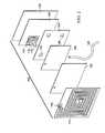
- FIG. 1is a schematic diagram, with a portion shown in cross section, of an illustrative embodiment of a system for treating a tissue site with reduced pressure;
- FIG. 2is a schematic, exploded, perspective view of an illustrative embodiment of a wireless, reduced-pressure pump used as part of the system of FIG. 1 ;
- FIG. 3is a schematic diagram, with a portion shown in cross section, of the system of FIG. 1 presenting additional aspects and some alternatives;
- FIG. 4is a schematic, partial cross-sectional view of an illustrative embodiment of a wireless, reduced-pressure pump
- FIG. 5is a schematic, cross section of one illustrative embodiment of a micro-pump device for use as part of a system for treating a tissue site with reduced pressure such as in FIG. 1 ;
- FIG. 6is a schematic, perspective view of an illustrative embodiment of a wireless, reduced-pressure pump
- FIG. 7is a schematic, cross section of another illustrative embodiment of a wireless, reduced-pressure pump
- FIG. 8is a schematic, perspective view of the wireless, reduced-pressure pump of FIG. 7 ;
- FIG. 9is a schematic diagram, with a portion shown in perspective view, of an illustrative embodiment of a reduced-pressure system for treating a tissue site with reduced pressure;
- FIG. 10is a schematic, cross section of the reduced-pressure dressing shown in FIG. 9 taken along line 10 - 10 ;
- FIG. 11is a schematic, exploded, perspective view of the reduced-pressure dressing of FIGS. 9-10 ;
- FIG. 12is a schematic, cross section of an illustrative embodiment of a system for treating a tissue site with reduced pressure.
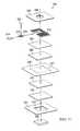
- FIG. 13is a schematic, exploded, perspective view of another illustrative embodiment of a reduced-pressure dressing.
- RFIDRadio Frequency Identification
- RFIDRadio Frequency Identification
- RFIDan enhanced type of Radio Frequency Identification
- RFIDRadio Frequency Identification
- RFIDRFID
- RFID tagsinclude an integrated circuit for storing and processing information, a modulator, and demodulator.
- RFID tagscan be passive tags, active RFID tags, and battery-assisted passive tags. Generally, passive tags use no battery and do not transmit information unless they are energized by a RFID reader.
- Active tagshave an on-board battery and can transmit autonomously (i.e., without being energized by a RFID reader).
- Battery-assisted passive tagstypically have a small battery on-board that is activated in the presence of a RFID reader.
- a microcontroller and sensormay be incorporated into the reduced-pressure dressing.
- the RFID tag, a microcontroller and sensorallow sensing and optional computational functions.
- the RFID tag and microcontrollerpartially or entirely power a micro-pump.
- the enhanced RFID technologyis a Wireless Identification and Sensing Platform (WISP) device.
- WISPsinvolve powering and reading a WISP device, analogous to a RFID tag (or label), with a RFID reader.
- the WISP deviceharvests the power from the RFID reader's emitted radio signals and performs sensing functions (and optionally performs computational functions).
- the WISP devicetransmits a radio signal with information to the RFID reader.
- the WISP devicereceives power from the RFID reader.
- the WISP devicehas a tag or antenna, that harvests energy and a microcontroller (or processor) that can perform a variety of tasks, such as sampling sensors.
- the WISP devicereports data to the RFID reader.
- the WISP deviceincludes an integrated circuit with power harvesting circuitry, demodulator, modulator, microcontroller, sensors, and may include one or more capacitors for storing energy.
- a form of WISP technologyhas been developed by Intel Research Seattle.
- RFID devices as used hereinalso include WISP devices.
- the system 100includes a reduced-pressure dressing 106 for disposing proximate to the tissue site 102 ; a wireless, reduced-pressure pump 108 fluidly coupled to the reduced-pressure dressing 106 ; and a base unit 110 having a RFID reader 112 .
- the wireless, reduced-pressure pump 108includes a first RFID antenna 114 and a micro-pump device 116 .
- the RFID reader 112is configured to provide and transmit a pump signal that provides power to the first RFID antenna 114 .
- the pump signal received by the first RFID antenna 114powers the micro-pump device 116 .
- Remotely powering the micro-pump device 116provides a number of potential benefits. The benefits may include ease of application.
- the wireless, reduced-pressure pump 108may be a self-contained, disposable unit. It should be noted that some variation is shown between figures in order to show some of the potential variations in the illustrative system 100 .
- the system 100may be used with various different types of tissue sites 102 .
- the tissue site 102may be the bodily tissue of any human, animal, or other organism, including bone tissue, adipose tissue, muscle tissue, dermal tissue, vascular tissue, connective tissue, cartilage, tendons, ligaments, body cavity or any other tissue.
- Treatment of the tissue site 102may include removal of fluids, e.g., exudate or ascites.
- the wireless, reduced-pressure pump 108includes the first RFID antenna 114 that is coupled to a first processor 118 by electrical leads 119 .
- the first processor 118is coupled to the micro-pump device 116 , or micro-pump, for receiving power.
- the first processor 118may be incorporated into the micro-pump device 116 .
- the first processor 118 and micro-pump device 116may be located within a pump pouch 120 .
- the pump pouch 120may be formed by coupling a first pump-sealing member 122 to a second pump-sealing member 124 .
- the pump pouch 120may also be formed by other techniques such as casting the pump pouch 120 from a polymer.
- At least a portion of the pump pouch 120comprises a fluid reservoir 126 for receiving and retaining fluids 127 from the tissue site 102 .
- the micro-pump device 116may be a piezoelectric pump, a peristaltic pump, or other small pump that produces reduced pressure with minimal power requirements.
- the first processor 118is operable to receive a pressure message signal from a pressure sensing device 138 .
- the first processor 118In response to receiving the pressure message signal, the first processor 118 produces a control signal to activate or deactivate the micro-pump device 116 .
- the pressure sensing device 138may be a transducer or may be a simple switch that is activated if sufficient reduced pressure is present.
- the base unit 110includes a second processor 128 coupled to the RFID reader 112 .
- a control panel 130e.g., a user interface
- a first display 132 and a power source 134e.g., a battery or electrical connection
- the base unit 110may include a base housing 136 .
- the second processor 128 and RFID reader 112are configured to transmit a signal 137 , e.g., a pump signal or a pressure inquiry signal, to the first RFID antenna 114 .
- the first RFID antenna 114 of the reduced-pressure pump 108is coupled by electrical leads 119 or a wireless coupling to the first processor 118 .
- the first processor 118is coupled to the micro-pump device 116 to provide power and control the micro-pump device 116 .
- a first power source 140may be included to provide additional power to the first processor 118 .
- a pressure sensing device 138may be coupled to the first processor 118 .
- the pressure sensing device 138is fluidly coupled to and senses pressure in a pressure sensing lumen 166 (or vent passageway 174 or interface distribution manifold 150 ).
- the micro-pump device 116is fluidly coupled to a fluid reservoir 126 .
- the fluid reservoir 126receives and retains the fluids 127 from a reduced-pressure lumen 164 or from the interface distribution manifold 150 .
- the pump signal transmitted by the base unit 110is received by the first RFID antenna 114 and energizes the micro-pump device 116 to produce reduced pressure.
- the pressure inquiry signalis transmitted to the first processor 118 of the wireless, reduced-pressure pump 108 by the second processor 128 and RFID reader 112 .
- the first processor 118 and pressure sensing device 138 of the wireless, reduced-pressure pump 108transmit a pressure message signal indicative of the pressure experienced at the reduced-pressure dressing 106 to the base unit 110 .
- the second processor 128is configured to receive the pressure message signal from the wireless, reduced-pressure pump 108 and prepare a control signal.
- the second processor 128 and RFID reader 112are configured to transmit the control signal to the wireless, reduced-pressure pump 108 to activate or deactivate the micro-pump device 116 .
- the first processor 118is operable to receive a pressure message signal from the pressure sensing device 138 and to produce a control signal to activate or deactivate the micro-pump device 116 .
- the wireless, reduced-pressure pump 108generates reduced pressure that is delivered to the tissue site 102 .
- the wireless, reduced-pressure pump 108receives and retains fluids from the tissue site 102 .
- Reduced pressuregenerally refers to a pressure less than the ambient pressure at a tissue site that is being subjected to treatment. In most cases, this reduced pressure will be less than the atmospheric pressure at which the patient is located. Alternatively, the reduced pressure may be less than a hydrostatic pressure at the tissue site. Unless otherwise indicated, values of pressure stated herein are gauge pressures.
- the reduced pressure deliveredmay be constant or varied (patterned or random) and may be delivered continuously or intermittently. Consistent with the use herein, unless otherwise indicated, an increase in reduced pressure or vacuum pressure typically refers to a relative reduction in absolute pressure.
- the wireless, reduced-pressure pump 108provides the reduced pressure for the system 100 .
- the wireless, reduced-pressure pump 108may include a first distribution manifold 142 , a diverter layer 144 , and an absorbent layer 146 .
- a vent 176is used to fluidly couple an exhaust from the micro-pump device 116 to an exterior of the wireless, reduced-pressure pump 108 .
- the first distribution manifold 142functions to distribute reduced pressure generated by the micro-pump device 116 .
- An air/liquid separator 143e.g., a hydrophobic filter, may be placed between the micro-pump device 116 and the first distribution manifold 142 to prevent liquid from entering the micro-pump device 116 .
- the absorbent layer 146functions to receive and retain fluids from the tissue site 102 .
- the absorbent layer 146may be made from any material capable of absorbing liquid, such as exudate from the tissue site 102 .
- the absorbent layer 146may be made from super absorbent fibers.
- the super absorbent fibersmay retain or bond to the liquid in conjunction with a physical or chemical change to the fibers.
- the super absorbent fibermay include the Super Absorbent Fiber (SAF) material from Technical Absorbents, Ltd. of Grimsby, United Kingdom.
- SAFSuper Absorbent Fiber
- the absorbent layer 146may be a sheet or mat of fibrous material in which the fibers absorb liquid from the tissue site 102 .
- the structure of the absorbent layer 146 that contains the fibersmay be either woven or non-woven.
- the fibers in the absorbent layer 146may gel upon contact with the liquid, thereby trapping the liquid.
- Spaces or voids between the fibersmay allow reduced pressure that is applied to the absorbent layer 146 to be transferred within and through the absorbent layer 146 .
- the fiber density of the fibers in the absorbent layer 146may be approximately 1.4 grams per millimeter.
- the diverter layer 144is disposed adjacent to the absorbent layer 146 and the first distribution manifold 142 .
- the diverter layer 144is formed from a liquid impermeable material but contains a plurality of apertures 145 .
- the plurality of apertures 145allow reduced pressure from the micro-pump device 116 to be transmitted through the diverter layer 144 at desired locations.
- the diverter layer 144helps control the pattern of reduced pressure as applied to the absorbent layer 146 .
- the reduced pressureis distributed to the diverter layer 144 by the first distribution manifold 142 .
- the apertures 145may be arranged in a pattern for applying the reduced pressure to portions of the absorbent layer 146 to enhance the capability of the absorbent layer 146 to continue transferring reduced pressure to the tissue site 102 as the absorbent layer 146 absorbs more fluid from the tissue site 102 .
- the plurality of apertures 145may be positioned in a pattern around a peripheral portion of the diverter layer 144 away from the center of the diverter layer 144 such that the reduced pressure is applied to the absorbent layer 146 away from a center region of the absorbent layer 146 .
- the diverter layer 144acts in conjunction with the first distribution manifold 142 to ensure that the absorption capabilities and absorption efficiency of the absorbent layer 146 are increased relative to an absorbent layer 146 that is not used in conjunction with a diverter layer 144 .
- the diverter layer 144also increases the effective capacity and treatment time of the wireless, reduced-pressure pump 108 .
- the diverter layer 144may be made from any material that enhances the reduced pressure transmission and storage capabilities of an adjacent absorbent layer.
- the diverter layer 144may be made from a material that is substantially impermeable to liquid and gas and that diverts the reduced pressure to pass through apertures 145 .
- the material from which the diverter layer 144 is mademay have a predetermined moisture vapor transfer rate that is consistent with gas permeability.
- the diverter layer 144may still include a pattern of apertures for transmitting a greater volume of liquid or gas than that permitted by a gas-permeable material not having apertures. It should be noted, however, that permeability of the diverter layer 144 to gas but not liquid may result in increased transmission of reduced pressure through the dressing while still directing liquid flow around or near the perimeter of the diverter layer 144 .
- the first distribution manifold 142 , the diverter layer 144 , and the absorbent layer 146may be disposed within the pump pouch 120 .
- the wireless, reduced-pressure pump 108may also include the pressure sensing device 138 , which is fluidly coupled to the reduced-pressure dressing 106 and in communication with the first processor 118 for sensing pressure.
- the reduced-pressure conduit 148delivers fluids from the reduced-pressure dressing 106 to the wireless, reduced-pressure pump 108 .
- the reduced-pressure conduit 148is disposed directly into the absorbent layer 146 .
- an interface(not shown) fluidly couples the reduced-pressure conduit 148 and the absorbent layer 146 .
- the reduced-pressure dressing 106is disposed against the tissue site 102 .
- the tissue site 102may be, for example, the wound 104 through epidermis 156 and into subcutaneous tissue 158 or any other tissue site.
- the reduced-pressure dressing 106may be any device for providing reduced pressure to the tissue site 102 and for receiving fluids from the tissue site 102 .
- the reduced-pressure dressing 106may be formed with a foam member, a structure with a plurality of defined channels, a suction tube, or other device.
- the reduced-pressure dressing 106may include the interface distribution manifold 150 for placing proximate to the tissue site 102 , a dressing sealing member 152 , and a reduced-pressure interface 154 .
- a manifoldis a substance or structure that is provided to assist in applying reduced pressure to, delivering fluids to, or removing fluids from a tissue site 102 .
- the interface distribution manifold 150typically includes a plurality of flow channels or pathways that distribute fluids provided to and removed from the tissue site 102 around the interface distribution manifold 150 .
- the flow channels or pathwaysare interconnected to improve distribution of fluids provided or removed from the tissue site 102 .
- the interface distribution manifold 150may be a biocompatible material that is capable of being placed in contact with the tissue site 102 and distributing reduced pressure to the tissue site 102 .
- interface distribution manifoldsmay include without limitation the following: devices that have structural elements arranged to form flow channels, e.g., cellular foam, open-cell foam, porous tissue collections, liquids, gels, and foams that include, or cure to include, flow channels; foam; gauze; felted mat; or any other material suited to a particular biological application.
- devices that have structural elements arranged to form flow channelse.g., cellular foam, open-cell foam, porous tissue collections, liquids, gels, and foams that include, or cure to include, flow channels
- foamgauze; felted mat; or any other material suited to a particular biological application.
- the interface distribution manifold 150is a porous foam and includes a plurality of interconnected cells or pores that act as flow channels.
- the porous foammay be a polyurethane, open-cell, reticulated foam such as GranuFoam® material available from Kinetic Concepts, Incorporated of San Antonio, Tex.
- the interface distribution manifold 150may also be used to distribute fluids such as medications, antibacterials, growth factors, and various solutions to the tissue site 102 .
- Other layersmay be included in or on the interface distribution manifold 150 , such as absorptive materials, wicking materials, hydrophobic materials, and hydrophilic materials.
- the interface distribution manifold 150in whole or in part may be constructed from bioresorbable materials that may remain in a patient's body following use of the reduced-pressure dressing 106 .
- Suitable bioresorbable materialsmay include, without limitation, a polymeric blend of polylactic acid (PLA) and polyglycolic acid (PGA).
- the polymeric blendmay also include without limitation polycarbonates, polyfumarates, and capralactones.
- the interface distribution manifold 150may further serve as a scaffold for new cell-growth, or a scaffold material may be used in conjunction with the interface distribution manifold 150 to promote cell-growth.
- a scaffoldis a substance or structure used to enhance or promote the growth of cells or formation of tissue, such as a three-dimensional porous structure that provides a template for cell growth.
- Illustrative examples of scaffold materialsinclude calcium phosphate, collagen, PLA/PGA, coral hydroxy apatites, carbonates, or processed allograft materials.
- the interface distribution manifold 150is covered by a dressing sealing member 152 .
- the dressing sealing member 152may be any material that provides a fluid seal.
- a fluid sealis a seal adequate to maintain reduced pressure at a desired site given the particular reduced-pressure source or subsystem involved.
- the dressing sealing member 152may, for example, be an impermeable or semi-permeable, elastomeric material.
- Elastomeric materialshave the properties of an elastomer. It generally refers to a polymeric material that has rubber-like properties. More specifically, most elastomers have ultimate elongations greater than 100% and a significant amount of resilience. The resilience of a material refers to the material's ability to recover from an elastic deformation.
- elastomersinclude, but are not limited to, natural rubbers, polyisoprene, styrene butadiene rubber, chloroprene rubber, polybutadiene, nitrile rubber, butyl rubber, ethylene propylene rubber, ethylene propylene diene monomer, chlorosulfonated polyethylene, polysulfide rubber, polyurethane (PU), EVA film, co-polyester, and silicones.
- Additional, specific examples of dressing sealing member materialsinclude a silicone drape, 3M Tegaderm drape, polyurethane (PU) drape such as one available from Avery Dennison Corporation of Pasadena, Calif.
- the dressing sealing member 152forms a sealed space 160 over the tissue site 102 , which may or may contain the micro-pump device 116 .
- An attachment device 162may be used to retain the dressing sealing member 152 against the patient's epidermis 156 or another layer, such as a gasket or additional sealing member.
- the attachment device 162may take numerous forms.
- the attachment device 162may be a medically acceptable, pressure-sensitive adhesive that extends about a periphery or all of the dressing sealing member 152 or covers at least a potion of the dressing sealing member 152 on a patient-facing side over the epidermis 156 .
- the reduced-pressure interface 154may be used to provide fluid communication between the reduced-pressure conduit 148 and the sealed space 160 of the reduced-pressure dressing 106 .
- the reduced pressuremay be delivered through the reduced-pressure conduit 148 to the reduced-pressure interface 154 and then to the sealed space 160 .
- the reduced-pressure interface 154is a T.R.A.C.® Pad or Sensa T.R.A.C.® Pad available from KCI of San Antonio, Tex.
- the reduced-pressure conduit 148may include the reduced-pressure lumen 164 and the pressure sensing lumen 166 formed as an integral conduit as shown in FIG. 1 or separately as shown in FIG. 3 .
- pressure sensing capabilitymay be added to the reduced-pressure dressing 106 to function in addition to or in lieu of pressure sensing device 138 .
- the reduced-pressure dressing 106may include a second RFID antenna 168 , a third processor 170 , and a second pressure sensing device 172 .
- the third processor 170is coupled to the second RFID antenna 168 and to the second pressure sensing device 172 .
- a vent passageway 174provides fluid communication between the sealed space 160 and the second pressure sensing device 172 .
- the third processor 170 and the second pressure sensing device 172are operable to receive a pressure inquiry signal from the base unit 110 and respond with a pressure message signal indicative of the pressure in the sealed space 160 .
- the wireless, reduced-pressure pump 108is a wireless and passive (i.e., no battery) device. As such, the wireless, reduced-pressure pump 108 has no source of power other than power delivered through the first RFID antenna 114 .
- the wireless, reduced-pressure pump 108may contain a capacitor for storing electrical energy.
- the first power source 140 as shown in FIG. 3may be provided to augment the power delivered through the first RFID antenna 114 or to operate the micro-pump device 116 . The first power source 140 may be recharged by power from the first RFID antenna 114 .
- the micro-pump device 116may take numerous forms such as a piezoelectric pump, peristaltic pump, or other miniaturized pump. Referring now primarily to FIG. 5 , an illustrative embodiment of a micro-pump device 116 that is suitable for use as an aspect of the wireless, reduced-pressure pump 108 is presented.
- the micro-pump device 116includes a cavity 178 that is defined by a first end wall 180 , a second end wall 182 , and an annular side wall 184 .
- the cavity 178may be substantially circular in shape, but other shapes are possible, such as elliptical. In one illustrative embodiment, the cavity 178 may hold about 10 ml of fluid or may hold more or less.
- the cavity 178is provided with a nodal inlet 186 , which may be valved or unvalved.
- the cavity 178may also have a valved outlet 190 .
- the first end wall 180may be a disc 192 .
- an actuator 194such as a piezoelectric disc, magnetostrictive device, or solenoid actuated device.
- the actuator 194is electrically coupled to a drive circuit, which is controlled by the processor.
- the drive circuitwill apply an alternating electrical signal to the actuator 194 to induce an oscillation in the disc 192 .
- the frequency of the oscillationcan be adjusted to match the natural frequency of the chamber.
- the piezoelectric discmay be less than 1 mm in thickness and may be tuned to operate at more than 500 Hz, more than 10 kHz, or even higher than 20 kHz.
- the actuator 194may vibrate in a direction substantially perpendicular to the plane of the cavity 178 as shown, thereby generating radial pressure oscillations within the fluid in the cavity 178 .
- One or more micro-pump devices 116may be used in parallel or series.
- the micro-pump device 116has a fluid in the cavity 178 and has a substantially cylindrical shape that is bounded by the first end wall 180 , second end wall 182 , and side wall 184 . At least two apertures, e.g., inlet 186 and outlet 190 , are formed through the walls 180 , 182 , 184 forming the cavity 178 .
- the cavity 178has a radius, r, and a height, h, and r/h>1.2 and h 2 /r>4 ⁇ 10 ⁇ 10 m.
- the actuator 194which is a piezoelectric disc, creates an oscillatory motion of one of the end walls 180 , 182 in a direction that is substantially perpendicular to the plane of the first end wall 180 and second end wall 182 .
- Axial oscillations of the end walls 180 , 182drive radial oscillations of fluid pressure in the cavity 178 and allow for pumping that creates reduced pressure.
- the micro-pump device 116is like an acoustic pump in that an acoustic resonance is set up within the cavity 178 .
- the inlet 186is used to pull fluids, and the outlet 190 is coupled to a vent, e.g., the vent 176 in FIG. 4 , to discharge to an exterior.
- micro-pump device 116may be the type of micro-pump shown in United States Patent Publication 2009/0240185 (application Ser. No. 12/398,904; filed 5 Mar. 2009), entitled, “Dressing and Method for Applying Reduced Pressure To and Collecting And Storing Fluid from a Tissue Site,” which is incorporated herein for all purposes.
- the reduced-pressure dressing 106is applied to the tissue site 102 .
- the interface distribution manifold 150is disposed proximate to the tissue site 102 .
- the interface distribution manifold 150 and the tissue site 102are covered by the dressing sealing member 152 to create the sealed space 160 .
- the attachment device 162 on the patient-facing side of the dressing sealing member 152may help provide a fluid seal against a portion of the patient's epidermis 156 .
- the reduced-pressure interface 154may be applied, such as for example by cutting a small aperture in the dressing sealing member 152 and securing the reduced-pressure interface 154 over or through the aperture, or hole.
- the wireless, reduced-pressure pump 108is then provided and fluidly coupled by the reduced-pressure conduit 148 to the reduced-pressure interface 154 .
- the wireless, reduced-pressure pump 108is positioned such that the first RFID antenna 114 is placed within operating range of the base unit 110 .
- the first RFID antenna 114is placed within a few millimeters of the RFID reader 112 of the base unit 110 .
- the first RFID antenna 114may be placed as far away as ten meters from the RFID reader 112 . Any distance within the given range may be readily used.
- the base unit 110is then activated by the user.
- the base unit 110transmits a pump signal 137 to the wireless, reduced-pressure pump 108 .
- the pump signalis received by the first RFID antenna 114 , and the energy of the pump signal is delivered to the first processor 118 .
- the first processor 118provides energy to the micro-pump device 116 .
- the micro-pump 116creates reduced pressure that is delivered into the fluid reservoir 126 that is fluidly coupled to the reduced-pressure conduit 148 .
- the reduced pressureis delivered to the reduced-pressure dressing 106 through the reduced-pressure conduit 148 . Fluids from the tissue site 102 flow through the interface distribution manifold 150 , reduced-pressure interface 154 , and reduced-pressure conduit 148 into the fluid reservoir 126 .
- the pressure at the tissue site 102may be monitored directly or indirectly using a pressure sensing device, such as pressure sensing device 138 of FIG. 3 or second pressure sensing device 172 of FIG. 1 .
- a pressure sensing devicesuch as pressure sensing device 138 of FIG. 3 or second pressure sensing device 172 of FIG. 1 .
- the second processor 128 and the RFID reader 112 of the base unit 110may, separate from the pump signal or with the pump signal, transmit a pressure inquiry signal to the wireless, reduced-pressure pump 108 .
- the first processor 118 and pressure sensing device 138may prepare a pressure message signal to communicate a measurement of the pressure at the tissue site. Then, the pressure message signal may be used for further processing by the first processor 118 to develop a pump control signal for activating or deactivating the micro-pump 116 as may be needed.
- the first processor 118may transmit the pressure message signal via the first RFID antenna 114 to the RFID reader 112 . After arriving at the RFID reader 112 , the pressure message signal is delivered to the second processor 128 . Using the pressure message signal, the second processor 128 may prepare a pump control signal that is transmitted by the RFID reader 112 to the wireless, reduced-pressure pump 108 to deactivate or activate the micro-pump 116 as needed.
- an alarm signalis created by the base unit 110 or by the wireless, reduced-pressure pump 108 .
- the alarmmay be a separate audible device, visual alarm, or the micro-pump 116 may function at a different frequency range, e.g., lower, to make an audible noise for the alarm.
- the reduced-pressure dressing 106includes the second RFID antenna 168 that is coupled to the third processor 170 , which is coupled to the second pressure sensing device 172 .
- the second pressure sensing device 172experiences the pressure within the sealed space 160 via the vent passageway 174 .
- the base unit 110transmits a pressure inquiry signal to the second RFID antenna 168 .
- the second pressure sensing device 172 and third processor 170produce a pressure message signal that is transmitted by the second RFID antenna 168 to the base unit 110 .
- the base unit 110then produces a pump control signal that is transmitted to the wireless, reduced-pressure pump 108 to activate or deactivate the micro-pump 116 .
- the third processor 170may evaluate the pressure and prepare a pump control signal as part of a feedback or control loop.
- the wireless, reduced-pressure pump 108may be a self-contained, disposable pouch design that may be removably secured to a base unit 110 on a pole 196 .
- a pump pouch 120is formed with a first pump-sealing member 122 and a second pump-sealing member 124 .
- the perimeter of the pump pouch 120may include a first flange 123 and a second flange 125 .
- the pump pouch 120may be divided or partitioned into numerous compartments if desired. For example, a compartment (not explicitly shown) may be formed that has the micro-pump 116 within the compartment and another compartment may formed that contains the absorbent layer 146 .
- the flanges 123 , 125 on the illustrative embodiment of the pump pouch 120may be formed by welding, bonding or otherwise attaching portions of the first pump-sealing member 122 and second pump-sealing member 124 .
- the first flange 123may include one or more apertures 129 for receiving one or more posts 198 .
- the posts 198secure the pump pouch 120 adjacent to the base unit 110 .
- the reduced-pressure conduit 148may enter through an aperture 149 in the second flange 125 that provides a sealed, interference fit or has a coupling that provides a sealed connection. Other connections may be used.
- the first RFID antenna 114may be placed closest to the base unit 110 such that the first RFID antenna 114 is immediately adjacent to RFID reader 112 of the base unit 110 as shown best in FIG. 4 .
- the first RFID antenna 114is positioned two millimeters or one millimeter (1 mm) or less from the RFID reader 112 .
- the RFID reader 112 and the first RFID antenna 114may be substantially matched and aligned.
- the wireless, reduced-pressure pump 108may be attached to a post 198 with the first RFID antenna 114 facing outward towards a remotely located base unit 110 as suggested in FIG. 1 .
- the base unit 110may be located at a central hub area where the wireless, reduced-pressure pump 108 is monitored and powered using the base unit 110 , which may be as far away as ten meters or more.
- the base unit 110may include the control panel 130 and one or more displays 132 .
- the base unit 110may include a base housing or base body 136 .
- the base housing or body 136may include a shelf portion 199 that may provide physical support to a portion of the wireless, reduced-pressure pump 108 when the wireless, reduced-pressure pump 108 fills with fluids from the tissue site 102 .
- the wireless, reduced-pressure pump 108 shown in FIG. 6is shown before use. With the embodiments of FIGS. 4 and 6 , when the wireless, reduced-pressure pump 108 has reached its capacity for holding fluids, the micro-pump 116 may be deactivated and the user may dispose of the entire wireless, reduced-pressure pump 108 .
- the wireless, reduced-pressure pump 200may be used as part of a system for treating a tissue site, e.g., the system of FIG. 1 .
- the wireless, reduced-pressure pump 200includes a plurality of wall members 202 that form a first chamber 204 and a second chamber 206 .
- One of the plurality of wall members 202is a partitioning wall 208 that separates the first chamber 204 from the second chamber 206 .
- a micro-pump 210which is analogous to the micro-pump 116 of the previous figures, may be disposed within the first chamber 204 .
- the micro-pump 116is configured such that the inlet 212 that receives fluid (or said another way, discharges reduced pressure) is fluidly coupled to the second chamber 206 .
- the micro-pump 210has an outlet or vent 214 that is fluidly coupled to the first chamber 204 .
- the micro-pump 210vents positive pressure through outlet or vent 214 into the first chamber 204 .
- a portion of one of the plurality of wall members 202 that forms the first chamber 204contains an aperture 216 .
- An optional relief valve 218is coupled to the aperture 216 .
- the relief valve 218is configured to allow pressure within the first chamber 204 to vent to an exterior of the wireless, reduced-pressure pump 200 when the pressure exceeds a first threshold pressure.
- At least a portion of the plurality of wall members 202 that make up the second chamber 206includes an inflatable support member and typically a plurality of inflatable support members 220 . While a plurality of inflatable support members 220 are presented, it should be understood that a single inflatable support member may be used create the second chamber 206 .
- the inflatable support members 220are in fluid communication with the first chamber 204 , such as through a plurality of apertures 222 .
- the positive pressure within the first chamber 204fills the plurality of inflatable support members 220 .
- the plurality of inflatable support members 220gain relative rigidity that provides a structure that helps provide volume to the second chamber 206 .
- Fluids 223 from a tissue siteare received through a reduced-pressure conduit 224 into the volume of the second chamber 206 .
- the wireless, reduced-pressure pump 200which is shown in the shape of a pyramid, may be formed to take other shapes, e.g., a box, a cylinder, or any other shape.
- the micro-pump 210may be fully or partially powered by a pump signal delivered to a RFID antenna 226 .
- the RFID antenna 226is coupled to a first processor 228 .
- the first processor 228is electrically coupled to the micro-pump 210 by an electrical lead 230 , which may be contained in one of the plurality of wall members 202 but is shown separately in FIG. 7 .
- a floor portion 232 of the plurality of wall members 202may be contained within a platform member 234 .
- the reduced-pressure conduit 224is coupled to a reduced-pressure dressing, such as reduced-pressure dressing 106 of FIGS. 1 and 3 .
- a base unite.g., base unit 110 of FIG. 1 , is used to transmit a pump signal or a pump activation signal to the RFID antenna 226 of the wireless, reduced-pressure pump 200 .
- the pump signal received by the RFID antenna 226is delivered to the first processor 228 .
- Poweris delivered from the first processor 228 to the micro-pump 210 to energize micro-pump 210 .
- a spacer membermay cover the inlet 212 to avoid a vapor lock during start up before the inflatable support members 220 fill.
- the maximum volumeis achieved for the second chamber 206 . Meanwhile, the reduced pressure in the second chamber 206 is delivered to the reduced-pressure conduit 224 . Fluids 223 (including liquids) are introduced into the second chamber 206 .
- a reduced-pressure sensing devicee.g., analogous to pressure sensing device 138 in FIG. 3
- a reduced-pressure sensing devicemay be included in the reduced-pressure pump 200 .
- the reduced-pressure conduit 224may also have a pressure sensing lumen that is fluidly coupled to the reduced-pressure sensing device for measuring pressure at a distribution manifold. In both examples, the pressure sensing device is coupled to the first processor 228 to develop a pressure message signal.
- the pressure message signalmay be supplied in response to a pressure inquiry signal from a base unit or self-generated by the first processor 228 .
- the first processor 228may use the pressure message signal to develop a pump control signal that is delivered to the micro-pump 210 .
- the pressure message signalmay be transmitted to the base unit where a processor in the base unit may develop a pump control signal similar to the embodiments previously presented.
- the wireless, reduced-pressure pumps 108 , 200 previously presentedhave, instead of having RFID antennas, electrical leads or sockets and plugs between the pumps and base.
- the electrical leads or sockets and plugsmay readily plug into one another for communicating power and signals.
- the reduced-pressure system 300includes a wireless, reduced-pressure dressing 304 and a base unit 306 .
- the base unit 306may include a power connector 307 .
- the wireless, reduced-pressure dressing 304is a self-contained, disposable dressing that receives power and control from the base unit 306 .
- the base unit 306may be substantially adjacent to the wireless, reduced-pressure dressing 304 , e.g., within one or two millimeters, or up to 10 meters or more away or anywhere in between.
- the micro-pump 316may be separate from an absorbent layer or absorbent member 310 , such that after use, the micro-pump 316 may be readily separated. The micro-pump 316 may then be reconditioned and reused.
- the wireless, reduced-pressure dressing 304includes an interface distribution manifold 308 that is placed proximate to the tissue site 302 .
- the wireless, reduced-pressure dressing 304may also include an absorbent layer 310 , a RFID antenna 312 , and a first processor 314 .
- the RFID antenna 312is electrically coupled to the first processor 314 .
- the first processor 314is electrically coupled to the micro-pump 316 .
- the interface distribution manifold 308 , absorbent layer 310 , RFID antenna 312 , first processor 314 , and micro-pump 316may all be retained in place and secured in a sealed space 318 by one or more sealing members, such as sealing member 320 . Additional layers and components may be included in the wireless, reduced-pressure dressing 304 .
- FIGS. 9-11includes additional layers and components.
- the additional layers and componentsmay be arranged in different orders.
- a sealing layer 322is used to seal the wireless, reduced-pressure dressing 304 around the tissue site 302 .
- the sealing layer 322is formed with an aperture 323 for providing fluid communication to the interface distribution manifold 308 .
- a first internal distribution manifold 324is positioned in fluid communication with the interface distribution manifold 308 and the tissue site 302 .
- the absorbent layer 310is positioned in fluid communication with the first internal distribution manifold 324 , the interface distribution manifold 308 , and a tissue site 302 .
- a diverter layer 326is positioned adjacent to the absorbent layer 310 .
- a second internal distribution manifold 328is positioned in fluid communication with the diverter layer 326 .
- the diverter layer 326is formed with a plurality of apertures 327 that may take numerous patterns and forms.
- the diverter layer 326is shown in this particular illustrative embodiment with a plurality of apertures 327 forming a square pattern. The square pattern has corner apertures that are larger than the other apertures.
- a liquid-air separator 330is positioned adjacent to the second internal distribution manifold 328 .
- the micro-pump 316 , RFID antenna 312 , and first processor 314may be adjacent to the liquid-air separator 330 .
- a charcoal filter 332 or other odor relieving devicemay be positioned over an outlet 334 of the micro-pump 316 .
- the sealing member 320is formed with an aperture 336 that allows the outlet 334 of the micro-pump 316 to exhaust to an exterior of the wireless, reduced-pressure dressing 304 .
- the outlet 334 and aperture 336together form a vent 338 .
- the micro-pump 316may be a micro-pump that is small and light enough such that the integrated wireless, reduced-pressure dressing 304 is able to be maintained on the tissue site 302 . Furthermore, the size and weight of the micro-pump 316 may be such that the integrated reduced-pressure dressing 304 does not pull or otherwise adversely affect the tissue site 302 .
- the micro-pump 316may be a disk pump having a piezoelectric actuator similar to that previously described. Reference is also made to the pumps shown in United States Patent Publication 2009/0087323 and United States Patent Publication 2009/0240185, which are hereby incorporated by reference for all purposes.
- the micro-pump 316may be a peristaltic pump that is used for pumping a variety of fluids. It should be understood that alternative pump technologies may be utilized and that rotary, linear, or other configurations of pumps may be utilized.
- the micro-pump 316creates sufficient reduced pressure to be therapeutic for wound therapy.
- the micro-pump 316has sufficient flow, reduced pressure, and operation life characteristics to enable continuous application of reduced pressure treatment.
- the flowmay range between about 5-1000 ml/min and the reduced pressure may range between about ⁇ 50 and ⁇ 200 mm Hg ( ⁇ 6.6 to ⁇ 26.6 kPa). It should be understood that alternative ranges may be utilized depending on the configuration of the integrated, wireless, reduced-pressure dressing 304 , size of wound, or type of wound.
- multiple pumpsmay be positioned in a single dressing to deliver increased flow rates or vacuum levels as required.
- the micro-pump 316is disposed within the dressing to avoid conduits and external canisters for collection of wound exudate.
- the micro-pump 316includes the outlet 334 to release air or exhaust out of the reduced-pressure dressing 304 . If the outlet 334 is used, the outlet 334 is in fluid communication with, or may be positioned within, the aperture 336 of the sealing member 320 . Alternatively, the sealing member 320 may be sealed around an outlet port of the micro-pump 316 such that gas from the micro-pump 316 is able to exhaust directly through the aperture 336 . In the illustrative embodiment in FIGS.
- the outlet 334 of the micro-pump 316is oriented in a direction away from the liquid-air separator 330 (or hydrophobic filter) to avoid adding air to the wireless, reduced-pressure dressing 304 .
- the airexhausts through an aperture 336 in the sealing member 320 , which may include a one-way valve. Alternatively, the air or another gas could be exhausted through a gas-permeable portion of the sealing member 320 as long as the ability of the sealing member 320 to maintain reduced pressure is not affected.
- the piezoelectric actuator associated with the micro-pump 316may be driven at different frequencies to act as a buzzer or vibrating alert system at times.
- the alert systemmay alert a user to an alarm condition.
- the alarm conditionmay indicate the presence of a leak in the dressing, a change in reduced pressure as measured by a sensor, that the dressing has absorbed a maximum capacity of liquid as may be indicated by an indicator, or that one or more layers are no longer manifolding reduced pressure efficiently.
- Control electronicsmay be physically or functionally incorporated as part of the first processor 314 .
- the control electronicsmay be utilized to control operation of the micro-pump 316 .
- the control electronicsmay be analog or digital and be configured with a regulator to regulate speed or duty cycle at which the micro-pump 316 operates.
- the control electronicsmay be configured with a controller that receives sense signals from sensors or switches, e.g., a pressure sensing device (see 340 in FIG. 12 ).
- the sensorsmay be disposed throughout the wireless, reduced-pressure dressing 304 to sense parameters, such as pressure, temperature, moisture, chemistry, odor, or any other parameter that may be utilized in managing and controlling the micro-pump 316 .
- the control electronicsmay include a computer processor or programmable gate array or other control device. It should be understood that the control electronics may include any form of digital or analog components to perform the functions described herein.
- the control electronicsmay be or include the first processor 314 .
- the control electronicsmay be arranged to monitor and provide an alarm for certain conditions, e.g., (i) low pressure, (ii) excessive leak, (iii) level of absorbent layer, and (iv) battery state (if included).
- the control electronicsmay include electronics that monitor each of the parameters and generate an alarm signal (e.g., high-pitched beep, vibration, or light) using a speaker, vibrator, or illumination device, such as a light emitting diode (LED).
- an alarm signale.g., high-pitched beep, vibration, or light
- the control electronicsmay notify a medical professional, patient, or family member that a parameter is outside of a desired range. For example, if a pressure at the tissue site 302 is below a therapeutic level, a continuous tone may be generated.
- the RFID antenna 312is utilized to provide electric power to the micro-pump 316 and control electronics.
- a battery 342may also be used to provide stored energy to augment power from the RFID antenna 312 .
- the battery 342may be any size and shape and may be of any material, such as polymer.
- the battery 342may provide the entire needed power or a portion thereof.
- the battery 342may be recharged by power from the RFID antenna 312 .
- the battery 342may be configured with a voltage level sensor that is monitored by the control electronics, and the control electronics may provide an alarm when a low power level is detected.
- the battery 342may be directly connected to the micro-pump 316 .
- the battery 342may be connected to the control electronics or processor(s) that use power from the battery 342 to drive the micro-pump 316 .
- the control electronicsmay provide continuous, modulated power, such as a pulsewidth modulated (PWM) signal, to drive the micro-pump 316 .
- PWMpulsewidth modulated
- the sealing layer 322is adhered to or otherwise connected to the sealing member 320 that is used to drape or otherwise cover the components of the reduced-pressure dressing 304 .
- the sealing layer 322may include a medical-grade adhesive material or other sealing device that is strong enough to form a vacuum seal with epidermis around a wound of a patient.
- the sealing layer 322may be a band that has an aperture 323 that is slightly larger than the geometric parameters of the liquid-air separator 330 or other layer so that the sealing member 320 contacts epidermis around the tissue site 302 of the patient.
- the sealing member 320is impermeable to fluids, such as air and liquids.
- the sealing member 320may be adhered to the diverter layer 326 and the diverter layer 326 adhered to the sealing member 320 to create an upper dressing portion and a lower dressing portion.
- the upper dressing portionmay include the sealing member 320 , the micro-pump 316 and related components, the liquid-air separator 330 , the second internal distribution manifold 328 , and the diverter layer 326 .
- the lower dressing portionmay include the absorbent layer 310 , the first internal distribution manifold 324 , the sealing layer 322 , and the interface distribution manifold 308 .
- the wireless, reduced-pressure dressing 304may be configured to allow replacement of the lower dressing portion once the wireless, reduced-pressure dressing has absorbed a maximum capacity of fluid.
- the upper dressing portionmay be reused after the lower dressing portion is replaced. This allows multiple uses of the micro-pump 316 , while disposable portions of the dressing may be replaced.
- the micro-pump 316 , first processor 314 , and RFID antenna 312may be removed from the dressing for reuse and the remaining layers of the dressing replaced.
- only the absorbent layer 310may be replaced.
- only the absorbent layer 310 and the interface distribution manifold 308may be replaced.
- the charcoal filter 332may be utilized in the wireless, reduced-pressure dressing 304 to reduce odors created by the tissue site 302 and dispersed from the wireless, reduced-pressure dressing 304 .
- the charcoal filter 332may be disposed above a valve or other output vent from the micro-pump 316 to filter exhaust from the micro-pump 316 prior to being released from the integrated reduced-pressure dressing 304 . It should be understood that the charcoal filter 332 may be alternatively configured and disposed above or below the micro-pump 316 . In another illustrative embodiment, rather than using a charcoal filter, charcoal may be integrated into any or all of the different layers utilized in the integrated reduced-pressure dressing 304 .
- the reduced-pressure system 300 of FIGS. 9-11is applied by placing the interface distribution manifold 308 proximate to the tissue site 302 . Placing the sealing layer 322 over the interface distribution manifold 308 such that the aperture 323 is over the interface distribution manifold 308 .
- the first internal distribution manifold 324is placed adjacent to the first interface distribution manifold 308 and possibly a portion of the sealing layer 322 .
- the absorbent layer 310is placed adjacent to the first internal distribution manifold 324 .
- the diverter layer 326may be placed over all the components thus presented.
- the second internal distribution manifold 328may be placed adjacent to a portion of the diverter layer 326 along with the liquid-air separator 330 .
- the micro-pump 316 , RFID antenna 312 , and first processor 314may be applied.
- the components mentioned heremay also be pre-assembled as a dressing stack.
- the sealing member 320is used to create a seal that forms a sealed space 318 .
- the base unit 306is used to transmit a pump signal as before to the RFID antenna 312 that is received by the first processor 314 and is used to provide power to the micro-pump 316 .
- the first processor 314may further include one or more capacitors for holding power or one or more batteries such as a rechargeable battery.
- the pump signalcauses reduced pressure to be developed by the micro-pump 316 .
- the reduced pressureis transmitted to the tissue site 302 to remove fluids or to provide reduced pressure therapy.
- the fluids removed from the tissue site 302are transmitted within the reduced-pressure dressing 304 to the absorbent layer 310 where the fluids are retained or substantially retained.
- a pressure sensing devicemay be included as part of the wireless, reduced-pressure dressing 304 to provide a pressure message signal to the base unit 306 .
- the reduced-pressure system 300includes a wireless, reduced-pressure dressing 304 and a base unit 306 .
- the reduced-pressure system 300 in FIG. 12is analogous to the system presented in FIGS. 9-11 , except that the wireless, reduced-pressure dressing 304 includes fewer components and includes the addition of a pressure sensing device 340 that is electrically coupled to the first processor 314 .
- an optional battery 342is included.
- the battery 342may supplement power provided through the RFID antenna 312 or may be used as the primary power source and then recharged by the RFID antenna 312 .
- the RFID antenna 312receives power from the base unit 306 .
- the sealing member 320is shown secured to the epidermis 344 by an attachment device 346 . Components included in the previous dressing of FIGS. 9-11 have been assigned the same reference numerals and are not necessarily discussed further here.
- the reduced-pressure system 300 of FIG. 12may be used by first applying the interface distribution manifold 308 adjacent to the tissue site 302 .
- the absorbent layer 310is placed in fluid communication with the interface distribution manifold 308 .
- the liquid-air separator 330may be placed over the absorbent layer 310 .
- the RFID antenna 312 , pressure sensing device 340 , first processor 314 , micro-pump 316 , and battery 342are disposed on the liquid-air separator 330 .
- only some of the components, such as the micro-pump 316may be adjacent to the liquid-air separator 330 .
- the sealing member 320is applied over the tissue site 302 to create a sealed space 318 and to cover all the aforementioned components.
- the previously mentioned componentsmay be entirely or partially preassembled.
- the base unit 306transmits a pump signal or pump activation signal to the reduced-pressure dressing 304 that activates the micro-pump 316 .
- the micro-pump 316removes air or other fluids from the sealed space 318 and thereby initiates treatment of the tissue site 302 with reduced pressure.
- the base unit 306may also transmit a pressure inquiry signal.
- the RFID antenna 312 , the first processor 314 , and the pressure sensing device 340develop a pressure message signal that is transmitted by the RFID antenna to the RFID reader (not explicitly shown) of the base unit 306 .
- the base unit 306may include a processor (not explicitly shown) that receives the pressure message signal and develops a pump control signal to activate or deactivate the micro-pump 316 . If the reduced pressure is in the desired therapy range, the micro-pump 316 may be deactivated.
- the base unit 306may transmit a pump signal that activates or continues the micro-pump 316 to produce more reduced pressure. If more than a sufficient elapsed time has passed without the desired pressure being reached, an alarm may be triggered by the base unit 306 .
- the wireless, reduced-pressure dressing 304may include a galvanic cell (not explicitly shown) to provide a full indication message signal when exudate or other body fluids electrically couple two electrodes. The full indication message signal would be transmitted with the RFID antenna 312 to the base unit 306 indicating that the dressing is full.
- a reduced-pressure dressing 400that includes a wireless, reduced-pressure pump 430 .
- the reduced-pressure dressing 400is shown in an exploded view over a tissue site 402 , such as a wound, on a patient 404 .
- the reduced-pressure dressing 400includes an interface distribution manifold 406 , which is disposed proximate the tissue site 402 .
- the interface distribution manifold 406may be formed from any manifold material, such as a GranuFoam® material or any other manifold material previously mentioned.
- the reduced-pressure dressing 400further includes a lower drape or diverter 408 .
- the lower drape 408may be a polyethylene material having adhesive on a lower side (tissue-facing side) that adheres to the patient 404 surrounding the tissue site 402 being treated.
- the lower drape 408includes apertures or perforations for communicating reduced pressure through the interface distribution manifold 406 to the tissue site 402 and drawing wound fluids (liquids or gases) from the tissue site 402 .
- the lower drape 408may also include a sealing ring 410 to provide additional adhesive strength to maintain the reduced pressure at a desired therapeutic level.
- a protective release liner 412may initially cover the sealing ring 410 . The protective release liner 412 is removed from the lower side of the lower drape 408 before the lower drape 408 is positioned on the patient 404 .
- the reduced-pressure dressing 400includes an absorbent layer 414 that may be a non-woven fabric for absorbing the wound liquids being drawn through the apertures of the lower drape 408 .
- the absorbent layer 414is sandwiched between two wicking layers 416 , 418 that wick and manifold the wound fluid to the absorbent layer 414 .
- the dense side of the wicking layers 416 , 418face away from the absorbent layer 414 .
- the wicking layers 416 , 418sandwich the absorbent layer 414 to form a fluid storage device 420 .
- the reduced-pressure dressing 400further includes an upper drape 422 that may be a non-porous, occlusive barrier formed of polyethylene.
- the smooth side of the upper drape 422faces the upper wicking layer 416 .
- the upper drape 422includes a aperture or opening 424 .
- the aperture or opening 424is covered by a hydrophobic filter 426 that separates air from liquid to contain the wound liquids or exudates within the absorbent layer 414 .
- the hydrophobic filter 426simultaneously permits the flow of gas from the absorbent layer 414 as a result of reduced pressure being applied to the hydrophobic filter 426 .
- the upper drape 422 and the hydrophobic filter 426comprise a top layer 428 of the reduced-pressure dressing 400 that covers the fluid storage device 420 . All the elements of the dressing assembly described above except the release liner 412 may be referred to collectively as the “wound dressing” portion of the reduced-pressure dressing 400 .
- the reduced-pressure dressing 400further includes the wireless, reduced-pressure pump, or pump portion 430 .
- the pump portion 430includes a micro-pump assembly 432 positioned on top of the upper drape 422 to provide a reduced pressure for drawing air through the hydrophobic filter 426 , the fluid storage device 420 , and the interface distribution manifold 406 .
- the micro-pump assembly 432includes a piezoelectric disc pump 434 that vibrates at a predetermined frequency to generate a desired reduced pressure at the input of the piezoelectric disc pump 434 .
- the piezoelectric disc pump 434may be analogous to micro-pump 316 of FIG. 12 .
- the piezoelectric disc pump 434 of the micro-pump assembly 432may not operate if any liquid drawn from the tissue site 402 into the absorbent layer 414 below the upper drape 422 enters the input port of the piezoelectric disc pump 434 .
- the hydrophobic filter 426prevents wound liquids or exudates from flowing into the piezoelectric disc pump 434 of the micro-pump assembly 432 .
- the reduced-pressure dressing 400may also include a spacing ring or ring seal 436 positioned between the hydrophobic filter 426 and the inlet of the piezoelectric disc pump 434 to provide a cavity for air flow to the piezoelectric disc pump 434 of the micro-pump assembly 432 .
- the micro-pump assembly 432may be sandwiched between a first foam cushion 438 and second foam cushion 440 .
- the micro-pump assembly 432 , first cushion 438 , and second cushion 440are sandwiched between an outer ply 442 and an inner ply 444 and form a single composite package that is removably attached to the upper drape 422 .
- the outer ply 442includes apertures or perforations 446 that provide an exhaust path for the output of the micro-pump assembly 432 .
- the piezoelectric disc pump 434 or other micro-pumpmay be controlled by a first processor 448 and other control electronics.
- the piezoelectric disc pump 434may be powered by a first power unit 450 and a second power unit 452 .
- the power units 450 , 452may be batteries.
- the first power unit 450 or the second power unit 452may comprise a RFID antenna that provides power to the first processor 448 and to the piezoelectric disc pump 434 .
Landscapes
- Health & Medical Sciences (AREA)
- Heart & Thoracic Surgery (AREA)
- Public Health (AREA)
- Veterinary Medicine (AREA)
- Vascular Medicine (AREA)
- Life Sciences & Earth Sciences (AREA)
- Animal Behavior & Ethology (AREA)
- General Health & Medical Sciences (AREA)
- Engineering & Computer Science (AREA)
- Biomedical Technology (AREA)
- Anesthesiology (AREA)
- Hematology (AREA)
- Media Introduction/Drainage Providing Device (AREA)
- External Artificial Organs (AREA)
- Infusion, Injection, And Reservoir Apparatuses (AREA)
- Measuring And Recording Apparatus For Diagnosis (AREA)
Abstract
Description
Claims (17)
Priority Applications (2)
| Application Number | Priority Date | Filing Date | Title |
|---|---|---|---|
| US13/183,136US8579872B2 (en) | 2010-10-27 | 2011-07-14 | Reduced-pressure systems, dressings, and methods employing a wireless pump |
| US14/047,394US9265867B2 (en) | 2010-10-27 | 2013-10-07 | Reduced-pressure systems, dressings, and methods employing a wireless pump |
Applications Claiming Priority (5)
| Application Number | Priority Date | Filing Date | Title |
|---|---|---|---|
| US40719410P | 2010-10-27 | 2010-10-27 | |
| US41873010P | 2010-12-01 | 2010-12-01 | |
| US201161445338P | 2011-02-22 | 2011-02-22 | |
| US201161445383P | 2011-02-22 | 2011-02-22 | |
| US13/183,136US8579872B2 (en) | 2010-10-27 | 2011-07-14 | Reduced-pressure systems, dressings, and methods employing a wireless pump |
Related Child Applications (1)
| Application Number | Title | Priority Date | Filing Date |
|---|---|---|---|
| US14/047,394ContinuationUS9265867B2 (en) | 2010-10-27 | 2013-10-07 | Reduced-pressure systems, dressings, and methods employing a wireless pump |
Publications (2)
| Publication Number | Publication Date |
|---|---|
| US20120109083A1 US20120109083A1 (en) | 2012-05-03 |
| US8579872B2true US8579872B2 (en) | 2013-11-12 |
Family
ID=45994285
Family Applications (3)
| Application Number | Title | Priority Date | Filing Date |
|---|---|---|---|
| US13/182,934AbandonedUS20120109034A1 (en) | 2010-10-27 | 2011-07-14 | Interactive, wireless reduced-pressure dressings, methods, and systems |
| US13/183,136Active2031-10-20US8579872B2 (en) | 2010-10-27 | 2011-07-14 | Reduced-pressure systems, dressings, and methods employing a wireless pump |
| US14/047,394Active2031-11-17US9265867B2 (en) | 2010-10-27 | 2013-10-07 | Reduced-pressure systems, dressings, and methods employing a wireless pump |
Family Applications Before (1)
| Application Number | Title | Priority Date | Filing Date |
|---|---|---|---|
| US13/182,934AbandonedUS20120109034A1 (en) | 2010-10-27 | 2011-07-14 | Interactive, wireless reduced-pressure dressings, methods, and systems |
Family Applications After (1)
| Application Number | Title | Priority Date | Filing Date |
|---|---|---|---|
| US14/047,394Active2031-11-17US9265867B2 (en) | 2010-10-27 | 2013-10-07 | Reduced-pressure systems, dressings, and methods employing a wireless pump |
Country Status (8)
| Country | Link |
|---|---|
| US (3) | US20120109034A1 (en) |
| EP (2) | EP2632406B1 (en) |
| JP (2) | JP2014500739A (en) |
| CN (2) | CN103179930B (en) |
| AU (2) | AU2011320911B2 (en) |
| CA (2) | CA2814742A1 (en) |
| TW (2) | TW201217021A (en) |
| WO (2) | WO2012057882A1 (en) |
Cited By (52)
| Publication number | Priority date | Publication date | Assignee | Title |
|---|---|---|---|---|
| US20120016322A1 (en)* | 2010-07-19 | 2012-01-19 | Kci Licensing, Inc. | Systems and methods for electrically detecting the presence of exudate in dressings |
| US20140005618A1 (en)* | 2012-06-28 | 2014-01-02 | Christopher Brian Locke | Wound connection pad with rfid and integrated strain gauge pressure sensor |
| US9770369B2 (en) | 2014-08-08 | 2017-09-26 | Neogenix, Llc | Wound care devices, apparatus, and treatment methods |
| US10046096B2 (en) | 2012-03-12 | 2018-08-14 | Smith & Nephew Plc | Reduced pressure apparatus and methods |
| US10624794B2 (en) | 2018-02-12 | 2020-04-21 | Healyx Labs, Inc. | Negative pressure wound therapy systems, devices, and methods |
| US10682446B2 (en) | 2014-12-22 | 2020-06-16 | Smith & Nephew Plc | Dressing status detection for negative pressure wound therapy |
| USD898925S1 (en) | 2018-09-13 | 2020-10-13 | Smith & Nephew Plc | Medical dressing |
| US10828403B2 (en) | 2014-12-29 | 2020-11-10 | Smith & Nephew Plc | Negative pressure wound therapy apparatus and methods for operating the apparatus |
| US11027051B2 (en) | 2010-09-20 | 2021-06-08 | Smith & Nephew Plc | Pressure control apparatus |
| US11076997B2 (en) | 2017-07-25 | 2021-08-03 | Smith & Nephew Plc | Restriction of sensor-monitored region for sensor-enabled wound dressings |
| US11096831B2 (en) | 2016-05-03 | 2021-08-24 | Smith & Nephew Plc | Negative pressure wound therapy device activation and control |
| US11116669B2 (en) | 2016-08-25 | 2021-09-14 | Smith & Nephew Plc | Absorbent negative pressure wound therapy dressing |
| US11123471B2 (en) | 2017-03-08 | 2021-09-21 | Smith & Nephew Plc | Negative pressure wound therapy device control in presence of fault condition |
| US11160915B2 (en) | 2017-05-09 | 2021-11-02 | Smith & Nephew Plc | Redundant controls for negative pressure wound therapy systems |
| US11173240B2 (en) | 2016-05-03 | 2021-11-16 | Smith & Nephew Plc | Optimizing power transfer to negative pressure sources in negative pressure therapy systems |
| US11285047B2 (en) | 2016-04-26 | 2022-03-29 | Smith & Nephew Plc | Wound dressings and methods of use with integrated negative pressure source having a fluid ingress inhibition component |
| US11305047B2 (en) | 2016-05-03 | 2022-04-19 | Smith & Nephew Plc | Systems and methods for driving negative pressure sources in negative pressure therapy systems |
| US11324424B2 (en) | 2017-03-09 | 2022-05-10 | Smith & Nephew Plc | Apparatus and method for imaging blood in a target region of tissue |
| US11497653B2 (en) | 2017-11-01 | 2022-11-15 | Smith & Nephew Plc | Negative pressure wound treatment apparatuses and methods with integrated electronics |
| US11554203B2 (en) | 2017-11-01 | 2023-01-17 | Smith & Nephew Plc | Negative pressure wound treatment apparatuses and methods with integrated electronics |
| US11559438B2 (en) | 2017-11-15 | 2023-01-24 | Smith & Nephew Plc | Integrated sensor enabled wound monitoring and/or therapy dressings and systems |
| US11564845B2 (en) | 2017-09-13 | 2023-01-31 | Smith & Nephew Plc | Negative pressure wound treatment apparatuses and methods with integrated electronics |
| US11564847B2 (en) | 2016-09-30 | 2023-01-31 | Smith & Nephew Plc | Negative pressure wound treatment apparatuses and methods with integrated electronics |
| US11596553B2 (en) | 2017-09-27 | 2023-03-07 | Smith & Nephew Plc | Ph sensing for sensor enabled negative pressure wound monitoring and therapy apparatuses |
| US11633147B2 (en) | 2017-09-10 | 2023-04-25 | Smith & Nephew Plc | Sensor enabled wound therapy dressings and systems implementing cybersecurity |
| US11633153B2 (en) | 2017-06-23 | 2023-04-25 | Smith & Nephew Plc | Positioning of sensors for sensor enabled wound monitoring or therapy |
| US11638664B2 (en) | 2017-07-25 | 2023-05-02 | Smith & Nephew Plc | Biocompatible encapsulation and component stress relief for sensor enabled negative pressure wound therapy dressings |
| US11690570B2 (en) | 2017-03-09 | 2023-07-04 | Smith & Nephew Plc | Wound dressing, patch member and method of sensing one or more wound parameters |
| US11701265B2 (en) | 2017-09-13 | 2023-07-18 | Smith & Nephew Plc | Negative pressure wound treatment apparatuses and methods with integrated electronics |
| US11707564B2 (en) | 2017-11-01 | 2023-07-25 | Smith & Nephew Plc | Safe operation of integrated negative pressure wound treatment apparatuses |
| US11717447B2 (en) | 2016-05-13 | 2023-08-08 | Smith & Nephew Plc | Sensor enabled wound monitoring and therapy apparatus |
| US11723809B2 (en) | 2016-03-07 | 2023-08-15 | Smith & Nephew Plc | Wound treatment apparatuses and methods with negative pressure source integrated into wound dressing |
| US11759144B2 (en) | 2017-09-10 | 2023-09-19 | Smith & Nephew Plc | Systems and methods for inspection of encapsulation and components in sensor equipped wound dressings |
| US11791030B2 (en) | 2017-05-15 | 2023-10-17 | Smith & Nephew Plc | Wound analysis device and method |
| US11839464B2 (en) | 2017-09-28 | 2023-12-12 | Smith & Nephew, Plc | Neurostimulation and monitoring using sensor enabled wound monitoring and therapy apparatus |
| US11883262B2 (en) | 2017-04-11 | 2024-01-30 | Smith & Nephew Plc | Component positioning and stress relief for sensor enabled wound dressings |
| US11925735B2 (en) | 2017-08-10 | 2024-03-12 | Smith & Nephew Plc | Positioning of sensors for sensor enabled wound monitoring or therapy |
| US11931165B2 (en) | 2017-09-10 | 2024-03-19 | Smith & Nephew Plc | Electrostatic discharge protection for sensors in wound therapy |
| US11944418B2 (en) | 2018-09-12 | 2024-04-02 | Smith & Nephew Plc | Device, apparatus and method of determining skin perfusion pressure |
| US11957545B2 (en) | 2017-09-26 | 2024-04-16 | Smith & Nephew Plc | Sensor positioning and optical sensing for sensor enabled wound therapy dressings and systems |
| US11969538B2 (en) | 2018-12-21 | 2024-04-30 | T.J.Smith And Nephew, Limited | Wound therapy systems and methods with multiple power sources |
| US12005182B2 (en) | 2019-05-31 | 2024-06-11 | T.J.Smith And Nephew, Limited | Systems and methods for extending operational time of negative pressure wound treatment apparatuses |
| US12011942B2 (en) | 2019-03-18 | 2024-06-18 | Smith & Nephew Plc | Rules for sensor integrated substrates |
| US12016994B2 (en) | 2019-10-07 | 2024-06-25 | Smith & Nephew Plc | Sensor enabled negative pressure wound monitoring apparatus with different impedances inks |
| US12033738B2 (en) | 2017-05-15 | 2024-07-09 | Smith & Nephew Plc | Negative pressure wound therapy system using eulerian video magnification |
| US12083263B2 (en) | 2019-03-20 | 2024-09-10 | Smith & Nephew Plc | Negative pressure wound treatment apparatuses and methods with integrated electronics |
| US12133789B2 (en) | 2014-07-31 | 2024-11-05 | Smith & Nephew, Inc. | Reduced pressure therapy apparatus construction and control |
| US12178597B2 (en) | 2017-03-09 | 2024-12-31 | Smith & Nephew Plc | Device, apparatus and method of determining skin perfusion pressure |
| US12186165B2 (en) | 2018-09-28 | 2025-01-07 | T.J.Smith And Nephew, Limited | Optical fibers for optically sensing through wound dressings |
| US12186164B2 (en) | 2018-10-16 | 2025-01-07 | Smith & Nephew Plc | Systems and method for applying biocompatible encapsulation to sensor enabled wound monitoring and therapy dressings |
| US12299772B2 (en) | 2020-04-21 | 2025-05-13 | T.J.Smith And Nephew, Limited | Wound treatment management using augmented reality overlay |
| US12409071B2 (en) | 2018-08-29 | 2025-09-09 | Smith & Nephew Plc | Component positioning and encapsulation for sensor enabled wound dressings |
Families Citing this family (105)
| Publication number | Priority date | Publication date | Assignee | Title |
|---|---|---|---|---|
| EP1905465B2 (en) | 2006-09-28 | 2013-11-27 | Smith & Nephew, Inc. | Portable wound therapy system |
| EP2214612B1 (en) | 2007-11-21 | 2019-05-01 | Smith & Nephew PLC | Wound dressing |
| AU2009221772B2 (en) | 2008-03-05 | 2015-01-22 | Solventum Intellectual Properties Company | Dressing and method for applying reduced pressure to and collecting and storing fluid from a tissue site |
| US8814842B2 (en) | 2010-03-16 | 2014-08-26 | Kci Licensing, Inc. | Delivery-and-fluid-storage bridges for use with reduced-pressure systems |
| US9526920B2 (en) | 2010-10-12 | 2016-12-27 | Smith & Nephew, Inc. | Medical device |
| US9084845B2 (en) | 2011-11-02 | 2015-07-21 | Smith & Nephew Plc | Reduced pressure therapy apparatuses and methods of using same |
| US10940047B2 (en) | 2011-12-16 | 2021-03-09 | Kci Licensing, Inc. | Sealing systems and methods employing a hybrid switchable drape |
| CN103987348B (en) | 2011-12-16 | 2016-05-11 | 凯希特许有限公司 | Releasable Medical Drapes |
| JP2015513027A (en)* | 2012-02-10 | 2015-04-30 | ケーシーアイ ライセンシング インコーポレイテッド | System and method for monitoring a disk pump system using RFID |
| WO2013149078A1 (en)* | 2012-03-28 | 2013-10-03 | Kci Licensing, Inc. | Reduced-pressure systems, dressings, and methods facilitating separation of electronic and clinical component parts |
| US10130518B2 (en)* | 2012-04-12 | 2018-11-20 | Elwha Llc | Appurtenances including sensors for reporting information regarding wound dressings |
| EP2836269B1 (en)* | 2012-04-12 | 2019-08-14 | Elwha LLC | Method and system for monitoring a wound dressings |
| US10158928B2 (en) | 2012-04-12 | 2018-12-18 | Elwha Llc | Appurtenances for reporting information regarding wound dressings |
| US10265219B2 (en)* | 2012-04-12 | 2019-04-23 | Elwha Llc | Wound dressing monitoring systems including appurtenances for wound dressings |
| US10226212B2 (en)* | 2012-04-12 | 2019-03-12 | Elwha Llc | Appurtenances to cavity wound dressings |
| US9084530B2 (en)* | 2012-04-12 | 2015-07-21 | Elwha Llc | Computational methods and systems for reporting information regarding appurtenances to wound dressings |
| US9024751B2 (en)* | 2012-04-12 | 2015-05-05 | Elwha Llc | Dormant to active appurtenances for reporting information regarding wound dressings |
| US9427505B2 (en) | 2012-05-15 | 2016-08-30 | Smith & Nephew Plc | Negative pressure wound therapy apparatus |
| EP2852333B1 (en) | 2012-05-22 | 2021-12-15 | Smith & Nephew plc | Apparatuses for wound therapy |
| CA2889440A1 (en) | 2012-10-25 | 2014-05-01 | Kci Licensing, Inc. | Wound connection pad with pneumatic connection confirmation ability |
| AU2013344686B2 (en) | 2012-11-16 | 2018-06-21 | Solventum Intellectual Properties Company | Medical drape with pattern adhesive layers and method of manufacturing same |
| EP2941232B2 (en)* | 2013-01-03 | 2019-04-10 | KCI Licensing, Inc. | Moisture absorbing seal |
| JP2016517318A (en) | 2013-03-14 | 2016-06-16 | スミス アンド ネフュー インコーポレーテッド | System and method for administering decompression therapy |
| US9737649B2 (en) | 2013-03-14 | 2017-08-22 | Smith & Nephew, Inc. | Systems and methods for applying reduced pressure therapy |
| CN105228688B (en) | 2013-03-15 | 2019-02-19 | 伊瑟拉医疗公司 | Vascular treatment devices and methods |
| US8715314B1 (en) | 2013-03-15 | 2014-05-06 | Insera Therapeutics, Inc. | Vascular treatment measurement methods |
| US10016543B2 (en)* | 2013-10-02 | 2018-07-10 | Kci Licensing, Inc. | Disposable reduced-pressure therapy system with electronic feedback |
| CN106170275B (en) | 2013-10-21 | 2021-05-07 | 史密夫和内修有限公司 | Negative pressure wound closure device |
| US10946124B2 (en) | 2013-10-28 | 2021-03-16 | Kci Licensing, Inc. | Hybrid sealing tape |
| EP3527237B1 (en) | 2013-10-30 | 2020-09-09 | KCI Licensing, Inc. | Absorbent conduit and system |
| EP3062751B1 (en) | 2013-10-30 | 2017-08-09 | KCI Licensing, Inc. | Condensate absorbing and dissipating system |
| US9956120B2 (en) | 2013-10-30 | 2018-05-01 | Kci Licensing, Inc. | Dressing with sealing and retention interface |
| AU2014342903B2 (en) | 2013-10-30 | 2018-09-20 | Solventum Intellectual Properties Company | Dressing with differentially sized perforations |
| US11026844B2 (en)* | 2014-03-03 | 2021-06-08 | Kci Licensing, Inc. | Low profile flexible pressure transmission conduit |
| US10031582B2 (en) | 2014-06-05 | 2018-07-24 | Immersion Corporation | Systems and methods for induced electrostatic haptic effects |
| JP6640748B2 (en) | 2014-06-05 | 2020-02-05 | ケーシーアイ ライセンシング インコーポレイテッド | Dressing with fluid acquisition and dispensing features |
| WO2016006457A1 (en)* | 2014-07-07 | 2016-01-14 | 株式会社村田製作所 | Negative-pressure closure therapy device |
| WO2016008154A1 (en)* | 2014-07-18 | 2016-01-21 | 科际精密股份有限公司 | Negative pressure wound therapy apparatus |
| US20170220755A1 (en)* | 2014-07-31 | 2017-08-03 | Smith & Nephew, Inc. | Inventory management and location tracking of medical devices |
| WO2016100098A1 (en) | 2014-12-17 | 2016-06-23 | Kci Licensing, Inc. | Dressing with offloading capability |
| DK3288508T3 (en) | 2015-04-27 | 2020-03-09 | Smith & Nephew | REDUCED PRESSURE DEVICES |
| EP3574877B1 (en) | 2015-05-08 | 2022-08-17 | 3M Innovative Properties Company | Low-acuity dressing with integral pump |
| EP3117807A1 (en)* | 2015-07-16 | 2017-01-18 | Carag AG | Multifunctional wound treatment dressing |
| EP3714916A1 (en) | 2015-07-29 | 2020-09-30 | Innovative Therapies Inc. | Wound therapy device pressure monitoring and control system |
| AU2016305091B2 (en) | 2015-08-13 | 2021-06-10 | Smith & Nephew, Inc. | Systems and methods for applying reduced pressure therapy |
| US9922525B2 (en)* | 2015-08-14 | 2018-03-20 | Gregory J. Hummer | Monitoring system for use with mobile communication device |
| EP3741335B1 (en) | 2015-09-01 | 2023-05-24 | KCI Licensing, Inc. | Dressing with increased apposition force |
| EP3349807B1 (en) | 2015-09-17 | 2021-02-24 | 3M Innovative Properties Company | Hybrid silicone and acrylic adhesive cover for use with wound treatment |
| US11315681B2 (en) | 2015-10-07 | 2022-04-26 | Smith & Nephew, Inc. | Reduced pressure therapy device operation and authorization monitoring |
| GB2543544A (en) | 2015-10-21 | 2017-04-26 | Brightwake Ltd | Wound dressing |
| CA3005094C (en)* | 2015-12-14 | 2021-05-25 | Buffalo Filter Llc | Method and apparatus for attachment and evacuation |
| US9928696B2 (en) | 2015-12-30 | 2018-03-27 | Immersion Corporation | Externally-activated haptic devices and systems |
| CN108697423A (en)* | 2016-02-16 | 2018-10-23 | 伊瑟拉医疗公司 | The part flow arrangement of suction unit and anchoring |
| US11311231B2 (en)* | 2016-03-29 | 2022-04-26 | Walgreen Health Solutions, Llc | Dressing assembly |
| GB201608099D0 (en) | 2016-05-09 | 2016-06-22 | Convatec Technologies Inc | Negative pressure wound dressing |
| CN109069713A (en) | 2016-05-13 | 2018-12-21 | 史密夫和内修有限公司 | Automatic wound in negative pressure wound treating system couples detection |
| DK3481349T3 (en) | 2016-07-08 | 2021-07-12 | Convatec Technologies Inc | Flexible vacuum system |
| EP3481348A4 (en) | 2016-07-08 | 2020-02-26 | ConvaTec Technologies Inc. | Fluid collection apparatus |
| MX2019000232A (en) | 2016-07-08 | 2019-11-12 | Convatec Technologies Inc | Fluid flow sensing. |
| US11096832B2 (en)* | 2016-09-27 | 2021-08-24 | Smith & Nephew Plc | Wound closure devices with dissolvable portions |
| GB201811494D0 (en)* | 2018-07-13 | 2018-08-29 | Smith & Nephew | Inter-device communications and device control in wound therapy systems |
| US12263294B2 (en) | 2016-09-28 | 2025-04-01 | T.J.Smith And Nephew, Limited | Systems and methods for operating negative pressure wound therapy devices |
| WO2018064077A2 (en)* | 2016-09-29 | 2018-04-05 | Smith & Nephew, Inc. | Construction and protection of components in negative pressure wound therapy systems |
| EP3551244A1 (en)* | 2016-12-12 | 2019-10-16 | Smith & Nephew PLC | Pressure wound therapy status indication via external device |
| EP3551147B1 (en)* | 2016-12-12 | 2023-08-09 | Smith & Nephew PLC | Wound dressing |
| TWI629072B (en)* | 2017-01-13 | 2018-07-11 | 廈門聖慈醫療器材有限公司 | Suction disc |
| US11395870B2 (en) | 2017-02-15 | 2022-07-26 | Smith & Nephew Asia Pacific Pte. Limited | Negative pressure wound therapy apparatuses and methods for using the same |
| JP7231227B2 (en)* | 2017-02-22 | 2023-03-01 | コーネル ユニヴァーシティー | Mechanical vacuum dressing for mechanical management, protection and aspiration of small incisions |
| WO2018165049A1 (en)* | 2017-03-07 | 2018-09-13 | Smith & Nephew, Inc. | Reduced pressure therapy systems and methods including an antenna |
| JP7155162B2 (en)* | 2017-06-14 | 2022-10-18 | ティージェイ スミス アンド ネフュー リミテッド | Negative pressure wound therapy unit |
| EP4066870B1 (en)* | 2017-06-15 | 2023-05-31 | Chiaro Technology Limited | Breast pump system |
| WO2019014141A1 (en) | 2017-07-10 | 2019-01-17 | Smith & Nephew, Inc. | Systems and methods for directly interacting with communications module of wound therapy apparatus |
| AU2018355151B2 (en) | 2017-10-23 | 2024-09-19 | Solventum Intellectual Properties Company | Area management of tissue sites on articulating joints |
| GB201718014D0 (en) | 2017-11-01 | 2017-12-13 | Smith & Nephew | Dressing for negative pressure wound therapy with filter |
| CA3084180A1 (en) | 2017-12-06 | 2019-06-13 | Cornell University | Manually-operated negative pressure wound therapy (npwt) bandage with improved pump efficiency, automatic pressure indicator and automatic pressure limiter |
| GB201813282D0 (en)* | 2018-08-15 | 2018-09-26 | Smith & Nephew | System for medical device activation and opertion |
| EP3735278A1 (en)* | 2018-01-02 | 2020-11-11 | KCI Licensing, Inc. | Negative pressure wound therapy device with silent piezoelectric pump |
| USD847864S1 (en) | 2018-01-22 | 2019-05-07 | Insera Therapeutics, Inc. | Pump |
| WO2019152140A1 (en)* | 2018-02-01 | 2019-08-08 | Kci Licensing, Inc. | Negative pressure wound therapy device using a vacuum generating pump providing audible therapy feedback |
| GB201804347D0 (en) | 2018-03-19 | 2018-05-02 | Smith & Nephew Inc | Securing control of settings of negative pressure wound therapy apparatuses and methods for using the same |
| GB201805584D0 (en)* | 2018-04-05 | 2018-05-23 | Smith & Nephew | Negative pressure wound treatment apparatuses and methods with integrated electronics |
| GB201806988D0 (en) | 2018-04-30 | 2018-06-13 | Quintanar Felix Clarence | Power source charging for negative pressure wound therapy apparatus |
| WO2019211731A1 (en)* | 2018-04-30 | 2019-11-07 | Smith & Nephew Pte. Limited | Systems and methods for controlling dual mode negative pressure wound therapy apparatus |
| GB201808438D0 (en) | 2018-05-23 | 2018-07-11 | Smith & Nephew | Systems and methods for determining blockages in a negative pressure wound therapy system |
| US11826234B2 (en) | 2018-06-28 | 2023-11-28 | Kci Licensing, Inc. | Distributed negative pressure wound therapy system incorporating an absorbent dressing and piezo-electric pump |
| WO2020018328A1 (en)* | 2018-07-16 | 2020-01-23 | Kci Licensing, Inc. | Wound therapy system with conduit blockage detection |
| GB201820668D0 (en) | 2018-12-19 | 2019-01-30 | Smith & Nephew Inc | Systems and methods for delivering prescribed wound therapy |
| US20220088288A1 (en)* | 2018-12-26 | 2022-03-24 | Kci Licensing, Inc. | Piezoelectric pump adapter for negative-pressure therapy |
| US12082997B2 (en)* | 2019-01-29 | 2024-09-10 | Kci Licensing, Inc. | Removable and replaceable dressing interface for a negative-pressure therapy system |
| GB201903778D0 (en)* | 2019-03-20 | 2019-05-01 | Smith & Nephew | Exhaust blockage detection for negative pressure wound treatment apparatuses |
| WO2020197759A1 (en)* | 2019-03-25 | 2020-10-01 | Kci Licensing, Inc. | Systems and methods for sensing ph of fluids on wound tissue interface |
| KR102238777B1 (en)* | 2019-04-02 | 2021-04-09 | 한국광기술원 | Wearable wound treatment device |
| GB2588482B (en) | 2019-07-03 | 2022-01-05 | Smith & Nephew | Negative pressure wound therapy dressing recognition, wound status detection, and therapy adjustment |
| GB201911693D0 (en) | 2019-08-15 | 2019-10-02 | Smith & Nephew | Systems and methods for monitoring essential performance of wound therapy |
| GB201914283D0 (en) | 2019-10-03 | 2019-11-20 | Smith & Nephew | Apparatuses and methods for negative pressure wound therapy |
| GB201914427D0 (en)* | 2019-10-07 | 2019-11-20 | Smith & Nephew | Negative pressure wound therapy systems and methods with multiple negative pressure sources |
| CA3171933A1 (en)* | 2020-02-20 | 2021-08-26 | Convatec Limited | A wound dressing and a wound therapy apparatus |
| GB202002339D0 (en)* | 2020-02-20 | 2020-04-08 | Convatec Ltd | A wound dressing and a wound therapy apparatus |
| GB202004395D0 (en) | 2020-03-26 | 2020-05-13 | Chiaro Technology Ltd | Lima |
| GB2615253B (en)* | 2020-10-05 | 2025-03-12 | Smith & Nephew | Temperature monitoring and control for negative pressure wound therapy systems |
| CN116710157A (en)* | 2020-11-11 | 2023-09-05 | 凯希制造无限公司 | Low profile discharge fluid and pressure conduit |
| US12220139B2 (en) | 2022-03-20 | 2025-02-11 | Von Vascular, Inc. | System, devices and methods for removing obstructions in body lumens |
| EP4531948A1 (en)* | 2022-05-24 | 2025-04-09 | Solventum Intellectual Properties Company | Modular negative pressure wound therapy systems |
| GB2622196A (en) | 2022-08-31 | 2024-03-13 | Chiaro Technology Ltd | Measurement system |
| CN119970127A (en)* | 2025-02-12 | 2025-05-13 | 中国人民解放军总医院海南医院 | A tissue stretching and closing device for wound repair |
Citations (123)
| Publication number | Priority date | Publication date | Assignee | Title |
|---|---|---|---|---|
| US1355846A (en) | 1920-02-06 | 1920-10-19 | David A Rannells | Medical appliance |
| US2547758A (en) | 1949-01-05 | 1951-04-03 | Wilmer B Keeling | Instrument for treating the male urethra |
| US2632443A (en) | 1949-04-18 | 1953-03-24 | Eleanor P Lesher | Surgical dressing |
| GB692578A (en) | 1949-09-13 | 1953-06-10 | Minnesota Mining & Mfg | Improvements in or relating to drape sheets for surgical use |
| US2682873A (en) | 1952-07-30 | 1954-07-06 | Johnson & Johnson | General purpose protective dressing |
| US2910763A (en) | 1955-08-17 | 1959-11-03 | Du Pont | Felt-like products |
| US2969057A (en) | 1957-11-04 | 1961-01-24 | Brady Co W H | Nematodic swab |
| US3066672A (en) | 1960-09-27 | 1962-12-04 | Jr William H Crosby | Method and apparatus for serial sampling of intestinal juice |
| US3367332A (en) | 1965-08-27 | 1968-02-06 | Gen Electric | Product and process for establishing a sterile area of skin |
| US3520300A (en) | 1967-03-15 | 1970-07-14 | Amp Inc | Surgical sponge and suction device |
| US3568675A (en) | 1968-08-30 | 1971-03-09 | Clyde B Harvey | Fistula and penetrating wound dressing |
| US3648692A (en) | 1970-12-07 | 1972-03-14 | Parke Davis & Co | Medical-surgical dressing for burns and the like |
| US3682180A (en) | 1970-06-08 | 1972-08-08 | Coilform Co Inc | Drain clip for surgical drain |
| US3826254A (en) | 1973-02-26 | 1974-07-30 | Verco Ind | Needle or catheter retaining appliance |
| DE2640413A1 (en) | 1976-09-08 | 1978-03-09 | Wolf Gmbh Richard | CATHETER MONITORING DEVICE |
| US4080970A (en) | 1976-11-17 | 1978-03-28 | Miller Thomas J | Post-operative combination dressing and internal drain tube with external shield and tube connector |
| US4096853A (en) | 1975-06-21 | 1978-06-27 | Hoechst Aktiengesellschaft | Device for the introduction of contrast medium into an anus praeter |
| US4139004A (en) | 1977-02-17 | 1979-02-13 | Gonzalez Jr Harry | Bandage apparatus for treating burns |
| US4165748A (en) | 1977-11-07 | 1979-08-28 | Johnson Melissa C | Catheter tube holder |
| US4184510A (en) | 1977-03-15 | 1980-01-22 | Fibra-Sonics, Inc. | Valued device for controlling vacuum in surgery |
| US4233969A (en) | 1976-11-11 | 1980-11-18 | Lock Peter M | Wound dressing materials |
| US4245630A (en) | 1976-10-08 | 1981-01-20 | T. J. Smith & Nephew, Ltd. | Tearable composite strip of materials |
| US4256109A (en) | 1978-07-10 | 1981-03-17 | Nichols Robert L | Shut off valve for medical suction apparatus |
| US4261363A (en) | 1979-11-09 | 1981-04-14 | C. R. Bard, Inc. | Retention clips for body fluid drains |
| US4275721A (en) | 1978-11-28 | 1981-06-30 | Landstingens Inkopscentral Lic, Ekonomisk Forening | Vein catheter bandage |
| US4284079A (en) | 1979-06-28 | 1981-08-18 | Adair Edwin Lloyd | Method for applying a male incontinence device |
| US4297995A (en) | 1980-06-03 | 1981-11-03 | Key Pharmaceuticals, Inc. | Bandage containing attachment post |
| US4333468A (en) | 1980-08-18 | 1982-06-08 | Geist Robert W | Mesentery tube holder apparatus |
| US4373519A (en) | 1981-06-26 | 1983-02-15 | Minnesota Mining And Manufacturing Company | Composite wound dressing |
| US4382441A (en) | 1978-12-06 | 1983-05-10 | Svedman Paul | Device for treating tissues, for example skin |
| US4392858A (en) | 1981-07-16 | 1983-07-12 | Sherwood Medical Company | Wound drainage device |
| US4392853A (en) | 1981-03-16 | 1983-07-12 | Rudolph Muto | Sterile assembly for protecting and fastening an indwelling device |
| US4419097A (en) | 1981-07-31 | 1983-12-06 | Rexar Industries, Inc. | Attachment for catheter tube |
| EP0100148A1 (en) | 1982-07-06 | 1984-02-08 | Dow Corning Limited | Medical-surgical dressing and a process for the production thereof |
| US4465485A (en) | 1981-03-06 | 1984-08-14 | Becton, Dickinson And Company | Suction canister with unitary shut-off valve and filter features |
| EP0117632A2 (en) | 1983-01-27 | 1984-09-05 | Johnson & Johnson Products Inc. | Adhesive film dressing |
| US4475909A (en) | 1982-05-06 | 1984-10-09 | Eisenberg Melvin I | Male urinary device and method for applying the device |
| US4480638A (en) | 1980-03-11 | 1984-11-06 | Eduard Schmid | Cushion for holding an element of grafted skin |
| US4525166A (en) | 1981-11-21 | 1985-06-25 | Intermedicat Gmbh | Rolled flexible medical suction drainage device |
| US4525374A (en) | 1984-02-27 | 1985-06-25 | Manresa, Inc. | Treating hydrophobic filters to render them hydrophilic |
| US4540412A (en) | 1983-07-14 | 1985-09-10 | The Kendall Company | Device for moist heat therapy |
| US4543100A (en) | 1983-11-01 | 1985-09-24 | Brodsky Stuart A | Catheter and drain tube retainer |
| US4548202A (en) | 1983-06-20 | 1985-10-22 | Ethicon, Inc. | Mesh tissue fasteners |
| US4551139A (en) | 1982-02-08 | 1985-11-05 | Marion Laboratories, Inc. | Method and apparatus for burn wound treatment |
| EP0161865A2 (en) | 1984-05-03 | 1985-11-21 | Smith and Nephew Associated Companies p.l.c. | Adhesive wound dressing |
| US4569348A (en) | 1980-02-22 | 1986-02-11 | Velcro Usa Inc. | Catheter tube holder strap |
| US4605399A (en) | 1984-12-04 | 1986-08-12 | Complex, Inc. | Transdermal infusion device |
| US4608041A (en) | 1981-10-14 | 1986-08-26 | Frese Nielsen | Device for treatment of wounds in body tissue of patients by exposure to jets of gas |
| US4640688A (en) | 1985-08-23 | 1987-02-03 | Mentor Corporation | Urine collection catheter |
| US4655754A (en) | 1984-11-09 | 1987-04-07 | Stryker Corporation | Vacuum wound drainage system and lipids baffle therefor |
| US4664662A (en) | 1984-08-02 | 1987-05-12 | Smith And Nephew Associated Companies Plc | Wound dressing |
| US4710165A (en) | 1985-09-16 | 1987-12-01 | Mcneil Charles B | Wearable, variable rate suction/collection device |
| US4733659A (en) | 1986-01-17 | 1988-03-29 | Seton Company | Foam bandage |
| GB2195255A (en) | 1986-09-30 | 1988-04-07 | Vacutec Uk Limited | Method and apparatus for vacuum treatment of an epidermal surface |
| US4743232A (en) | 1986-10-06 | 1988-05-10 | The Clinipad Corporation | Package assembly for plastic film bandage |
| GB2197789A (en) | 1986-11-28 | 1988-06-02 | Smiths Industries Plc | Anti-foaming disinfectants used in surgical suction apparatus |
| US4758220A (en) | 1985-09-26 | 1988-07-19 | Alcon Laboratories, Inc. | Surgical cassette proximity sensing and latching apparatus |
| US4787888A (en) | 1987-06-01 | 1988-11-29 | University Of Connecticut | Disposable piezoelectric polymer bandage for percutaneous delivery of drugs and method for such percutaneous delivery (a) |
| US4826494A (en) | 1984-11-09 | 1989-05-02 | Stryker Corporation | Vacuum wound drainage system |
| US4838883A (en) | 1986-03-07 | 1989-06-13 | Nissho Corporation | Urine-collecting device |
| US4840187A (en) | 1986-09-11 | 1989-06-20 | Bard Limited | Sheath applicator |
| US4863449A (en) | 1987-07-06 | 1989-09-05 | Hollister Incorporated | Adhesive-lined elastic condom cathether |
| US4872450A (en) | 1984-08-17 | 1989-10-10 | Austad Eric D | Wound dressing and method of forming same |
| US4878901A (en) | 1986-10-10 | 1989-11-07 | Sachse Hans Ernst | Condom catheter, a urethral catheter for the prevention of ascending infections |
| GB2220357A (en) | 1988-05-28 | 1990-01-10 | Smiths Industries Plc | Medico-surgical containers |
| US4897081A (en) | 1984-05-25 | 1990-01-30 | Thermedics Inc. | Percutaneous access device |
| US4906233A (en) | 1986-05-29 | 1990-03-06 | Terumo Kabushiki Kaisha | Method of securing a catheter body to a human skin surface |
| US4906240A (en) | 1988-02-01 | 1990-03-06 | Matrix Medica, Inc. | Adhesive-faced porous absorbent sheet and method of making same |
| US4919654A (en) | 1988-08-03 | 1990-04-24 | Kalt Medical Corporation | IV clamp with membrane |
| CA2005436A1 (en) | 1988-12-13 | 1990-06-13 | Glenda G. Kalt | Transparent tracheostomy tube dressing |
| US4941882A (en) | 1987-03-14 | 1990-07-17 | Smith And Nephew Associated Companies, P.L.C. | Adhesive dressing for retaining a cannula on the skin |
| US4953565A (en) | 1986-11-26 | 1990-09-04 | Shunro Tachibana | Endermic application kits for external medicines |
| US4969880A (en) | 1989-04-03 | 1990-11-13 | Zamierowski David S | Wound dressing and treatment method |
| US4985019A (en) | 1988-03-11 | 1991-01-15 | Michelson Gary K | X-ray marker |
| GB2235877A (en) | 1989-09-18 | 1991-03-20 | Antonio Talluri | Closed wound suction apparatus |
| US5037397A (en) | 1985-05-03 | 1991-08-06 | Medical Distributors, Inc. | Universal clamp |
| US5086170A (en) | 1989-01-16 | 1992-02-04 | Roussel Uclaf | Process for the preparation of azabicyclo compounds |
| US5092858A (en) | 1990-03-20 | 1992-03-03 | Becton, Dickinson And Company | Liquid gelling agent distributor device |
| US5100396A (en) | 1989-04-03 | 1992-03-31 | Zamierowski David S | Fluidic connection system and method |
| US5134994A (en) | 1990-02-12 | 1992-08-04 | Say Sam L | Field aspirator in a soft pack with externally mounted container |
| US5149331A (en) | 1991-05-03 | 1992-09-22 | Ariel Ferdman | Method and device for wound closure |
| US5167613A (en) | 1992-03-23 | 1992-12-01 | The Kendall Company | Composite vented wound dressing |
| US5176663A (en) | 1987-12-02 | 1993-01-05 | Pal Svedman | Dressing having pad with compressibility limiting elements |
| US5215522A (en) | 1984-07-23 | 1993-06-01 | Ballard Medical Products | Single use medical aspirating device and method |
| US5232453A (en) | 1989-07-14 | 1993-08-03 | E. R. Squibb & Sons, Inc. | Catheter holder |
| US5261893A (en) | 1989-04-03 | 1993-11-16 | Zamierowski David S | Fastening system and method |
| US5278100A (en) | 1991-11-08 | 1994-01-11 | Micron Technology, Inc. | Chemical vapor deposition technique for depositing titanium silicide on semiconductor wafers |
| US5279550A (en) | 1991-12-19 | 1994-01-18 | Gish Biomedical, Inc. | Orthopedic autotransfusion system |
| US5298015A (en) | 1989-07-11 | 1994-03-29 | Nippon Zeon Co., Ltd. | Wound dressing having a porous structure |
| US5342376A (en) | 1993-05-03 | 1994-08-30 | Dermagraphics, Inc. | Inserting device for a barbed tissue connector |
| US5344415A (en) | 1993-06-15 | 1994-09-06 | Deroyal Industries, Inc. | Sterile system for dressing vascular access site |
| DE4306478A1 (en) | 1993-03-02 | 1994-09-08 | Wolfgang Dr Wagner | Drainage device, in particular pleural drainage device, and drainage method |
| US5358494A (en) | 1989-07-11 | 1994-10-25 | Svedman Paul | Irrigation dressing |
| US5437651A (en) | 1993-09-01 | 1995-08-01 | Research Medical, Inc. | Medical suction apparatus |
| US5437622A (en) | 1992-04-29 | 1995-08-01 | Laboratoire Hydrex (Sa) | Transparent adhesive dressing with reinforced starter cuts |
| DE29504378U1 (en) | 1995-03-15 | 1995-09-14 | MTG Medizinisch, technische Gerätebau GmbH, 66299 Friedrichsthal | Electronically controlled low-vacuum pump for chest and wound drainage |
| US5527293A (en) | 1989-04-03 | 1996-06-18 | Kinetic Concepts, Inc. | Fastening system and method |
| US5549584A (en) | 1994-02-14 | 1996-08-27 | The Kendall Company | Apparatus for removing fluid from a wound |
| US5556375A (en) | 1994-06-16 | 1996-09-17 | Hercules Incorporated | Wound dressing having a fenestrated base layer |
| US5607388A (en) | 1994-06-16 | 1997-03-04 | Hercules Incorporated | Multi-purpose wound dressing |
| US5636643A (en) | 1991-11-14 | 1997-06-10 | Wake Forest University | Wound treatment employing reduced pressure |
| US5645081A (en) | 1991-11-14 | 1997-07-08 | Wake Forest University | Method of treating tissue damage and apparatus for same |
| GB2333965A (en) | 1997-09-12 | 1999-08-11 | Kci Medical Ltd | Surgical drape |
| US6071267A (en) | 1998-02-06 | 2000-06-06 | Kinetic Concepts, Inc. | Medical patient fluid management interface system and method |
| US6135116A (en) | 1997-07-28 | 2000-10-24 | Kci Licensing, Inc. | Therapeutic method for treating ulcers |
| US6241747B1 (en) | 1993-05-03 | 2001-06-05 | Quill Medical, Inc. | Barbed Bodily tissue connector |
| US6287316B1 (en) | 1999-03-26 | 2001-09-11 | Ethicon, Inc. | Knitted surgical mesh |
| KR20020032508A (en) | 2002-04-16 | 2002-05-03 | 주식회사 코스모지놈 | An adhesive infusion pump contoled by wireless remote control |
| US20020077661A1 (en) | 2000-12-20 | 2002-06-20 | Vahid Saadat | Multi-barbed device for retaining tissue in apposition and methods of use |
| US20020115951A1 (en) | 2001-02-22 | 2002-08-22 | Core Products International, Inc. | Ankle brace providing upper and lower ankle adjustment |
| US20020120185A1 (en) | 2000-05-26 | 2002-08-29 | Kci Licensing, Inc. | System for combined transcutaneous blood gas monitoring and vacuum assisted wound closure |
| US20020143286A1 (en) | 2001-03-05 | 2002-10-03 | Kci Licensing, Inc. | Vacuum assisted wound treatment apparatus and infection identification system and method |
| US6488643B1 (en) | 1998-10-08 | 2002-12-03 | Kci Licensing, Inc. | Wound healing foot wrap |
| US6493568B1 (en) | 1994-07-19 | 2002-12-10 | Kci Licensing, Inc. | Patient interface system |
| AU755496B2 (en) | 1997-09-12 | 2002-12-12 | Kci Licensing, Inc. | Surgical drape and suction head for wound treatment |
| US7191013B1 (en) | 2004-11-08 | 2007-03-13 | The United States Of America As Represented By The Administrator Of The National Aeronautics And Space Administration | Hand held device for wireless powering and interrogation of biomems sensors and actuators |
| US20070078366A1 (en)* | 2005-09-07 | 2007-04-05 | Kurt Haggstrom | Self contained wound dressing with micropump |
| US20080082059A1 (en)* | 2006-09-28 | 2008-04-03 | David Fink | Portable wound therapy system |
| WO2008051924A2 (en) | 2006-10-23 | 2008-05-02 | Abbott Diabetes Care, Inc. | Flexible patch for fluid delivery and monitoring body analytes |
| JP4129536B2 (en) | 2000-02-24 | 2008-08-06 | ヴェネテック インターナショナル,インコーポレイテッド | Highly compatible catheter anchoring system |
| US20090005727A1 (en)* | 2006-03-09 | 2009-01-01 | Searete Llc | Acoustically controlled substance delivery device |
| US20090227969A1 (en)* | 2008-03-05 | 2009-09-10 | Jonathan Paul Jaeb | Dressing and method for applying reduced pressure to and collecting and storing fluid from a tissue site |
| US20110112492A1 (en)* | 2008-04-04 | 2011-05-12 | Vivek Bharti | Wound dressing with micropump |
Family Cites Families (28)
| Publication number | Priority date | Publication date | Assignee | Title |
|---|---|---|---|---|
| US4266545A (en) | 1979-04-06 | 1981-05-12 | Moss James P | Portable suction device for collecting fluids from a closed wound |
| EP0256060A1 (en) | 1986-01-31 | 1988-02-24 | OSMOND, Roger L. W. | Suction system for wound and gastro-intestinal drainage |
| GB8906100D0 (en) | 1989-03-16 | 1989-04-26 | Smith & Nephew | Laminates |
| DE69505545T2 (en) | 1994-08-22 | 1999-03-11 | Kinetic Concepts Inc | WOUND DRAINAGE DEVICE |
| US8280682B2 (en)* | 2000-12-15 | 2012-10-02 | Tvipr, Llc | Device for monitoring movement of shipped goods |
| GB9523253D0 (en) | 1995-11-14 | 1996-01-17 | Mediscus Prod Ltd | Portable wound treatment apparatus |
| EP1343112A1 (en)* | 2002-03-08 | 2003-09-10 | EndoArt S.A. | Implantable device |
| CN1668358A (en)* | 2002-05-16 | 2005-09-14 | 斯科特实验室公司 | Medical supply kits for sedation and pain relief |
| EP2650028B1 (en)* | 2002-05-31 | 2017-08-09 | KCI Medical Resources | Wound treatment apparatus |
| DE20213196U1 (en)* | 2002-08-28 | 2004-01-15 | Campus Micro Technologies Gmbh | Device for measuring and monitoring local pressure loads acting on the human body |
| US7976519B2 (en) | 2002-12-31 | 2011-07-12 | Kci Licensing, Inc. | Externally-applied patient interface system and method |
| GB0408492D0 (en)* | 2004-04-16 | 2004-05-19 | Univ Strathclyde | Performance measurement of wound dressings |
| GB0508194D0 (en) | 2005-04-22 | 2005-06-01 | The Technology Partnership Plc | Pump |
| EP1893279A4 (en)* | 2005-06-21 | 2010-12-29 | Medrad Inc | Medical fluid injection and inflation system |
| ES2452480T3 (en)* | 2005-09-07 | 2014-04-01 | Hydranautics | Reverse osmosis filtration devices with flowmeters and conductivity meters fed by RFID tags |
| CA3045572C (en)* | 2005-09-07 | 2023-01-31 | Smith & Nephew, Inc. | Self contained wound dressing apparatus |
| JP5076167B2 (en)* | 2005-11-09 | 2012-11-21 | ザ インベンション サイエンス ファンド アイ,エルエルシー | Osmotic pump with remotely controlled osmotic pressure generation |
| US7779625B2 (en)* | 2006-05-11 | 2010-08-24 | Kalypto Medical, Inc. | Device and method for wound therapy |
| US20080041401A1 (en)* | 2006-08-15 | 2008-02-21 | Casola Robert P | Computer adjusted pressure wound care devices, systems & methods |
| US8366692B2 (en)* | 2008-01-08 | 2013-02-05 | Richard Scott Weston | Sustained variable negative pressure wound treatment and method of controlling same |
| WO2009093116A1 (en)* | 2008-01-25 | 2009-07-30 | The University Of Cape Town | Wound dressing system and method |
| KR100916616B1 (en)* | 2008-02-27 | 2009-09-14 | 인하대학교 산학협력단 | Medical treatment band using cellulose-chitosan film as a substrate and including RFID sensor and biosensor, and method of manufacturing the same |
| US8449508B2 (en)* | 2008-03-05 | 2013-05-28 | Kci Licensing, Inc. | Dressing and method for applying reduced pressure to and collecting and storing fluid from a tissue site |
| AU2009223037A1 (en)* | 2008-03-12 | 2009-09-17 | Smith & Nephew Plc | Negative pressure dressing and method of using same |
| US20090240218A1 (en)* | 2008-03-20 | 2009-09-24 | Tyco Healthcare Group Lp | Wound Therapy System |
| US20100022990A1 (en)* | 2008-07-25 | 2010-01-28 | Boehringer Technologies, L.P. | Pump system for negative pressure wound therapy and improvements thereon |
| US8486032B2 (en)* | 2008-12-24 | 2013-07-16 | Kci Licensing, Inc. | Reduced-pressure treatment systems and methods employing debridement mechanisms |
| US8377018B2 (en)* | 2009-12-23 | 2013-02-19 | Kci Licensing, Inc. | Reduced-pressure, multi-orientation, liquid-collection canister |
- 2011
- 2011-07-14USUS13/182,934patent/US20120109034A1/ennot_activeAbandoned
- 2011-07-14USUS13/183,136patent/US8579872B2/enactiveActive
- 2011-07-15CNCN201180050826.3Apatent/CN103179930B/ennot_activeExpired - Fee Related
- 2011-07-15CACA2814742Apatent/CA2814742A1/ennot_activeAbandoned
- 2011-07-15EPEP11738356.2Apatent/EP2632406B1/enactiveActive
- 2011-07-15AUAU2011320911Apatent/AU2011320911B2/ennot_activeCeased
- 2011-07-15JPJP2013536611Apatent/JP2014500739A/enactivePending
- 2011-07-15CACA2814740Apatent/CA2814740C/ennot_activeExpired - Fee Related
- 2011-07-15AUAU2011320912Apatent/AU2011320912B2/ennot_activeCeased
- 2011-07-15JPJP2013536610Apatent/JP5843296B2/ennot_activeExpired - Fee Related
- 2011-07-15WOPCT/US2011/044189patent/WO2012057882A1/enactiveApplication Filing
- 2011-07-15WOPCT/US2011/044187patent/WO2012057881A1/enactiveApplication Filing
- 2011-07-15EPEP11749596.0Apatent/EP2632407B1/ennot_activeNot-in-force
- 2011-07-15CNCN2011800504864Apatent/CN103179929A/enactivePending
- 2011-07-19TWTW100125499Apatent/TW201217021A/enunknown
- 2011-07-19TWTW100125498Apatent/TW201217020A/enunknown
- 2013
- 2013-10-07USUS14/047,394patent/US9265867B2/enactiveActive
Patent Citations (132)
| Publication number | Priority date | Publication date | Assignee | Title |
|---|---|---|---|---|
| US1355846A (en) | 1920-02-06 | 1920-10-19 | David A Rannells | Medical appliance |
| US2547758A (en) | 1949-01-05 | 1951-04-03 | Wilmer B Keeling | Instrument for treating the male urethra |
| US2632443A (en) | 1949-04-18 | 1953-03-24 | Eleanor P Lesher | Surgical dressing |
| GB692578A (en) | 1949-09-13 | 1953-06-10 | Minnesota Mining & Mfg | Improvements in or relating to drape sheets for surgical use |
| US2682873A (en) | 1952-07-30 | 1954-07-06 | Johnson & Johnson | General purpose protective dressing |
| US2910763A (en) | 1955-08-17 | 1959-11-03 | Du Pont | Felt-like products |
| US2969057A (en) | 1957-11-04 | 1961-01-24 | Brady Co W H | Nematodic swab |
| US3066672A (en) | 1960-09-27 | 1962-12-04 | Jr William H Crosby | Method and apparatus for serial sampling of intestinal juice |
| US3367332A (en) | 1965-08-27 | 1968-02-06 | Gen Electric | Product and process for establishing a sterile area of skin |
| US3520300A (en) | 1967-03-15 | 1970-07-14 | Amp Inc | Surgical sponge and suction device |
| US3568675A (en) | 1968-08-30 | 1971-03-09 | Clyde B Harvey | Fistula and penetrating wound dressing |
| US3682180A (en) | 1970-06-08 | 1972-08-08 | Coilform Co Inc | Drain clip for surgical drain |
| US3648692A (en) | 1970-12-07 | 1972-03-14 | Parke Davis & Co | Medical-surgical dressing for burns and the like |
| US3826254A (en) | 1973-02-26 | 1974-07-30 | Verco Ind | Needle or catheter retaining appliance |
| US4096853A (en) | 1975-06-21 | 1978-06-27 | Hoechst Aktiengesellschaft | Device for the introduction of contrast medium into an anus praeter |
| DE2640413A1 (en) | 1976-09-08 | 1978-03-09 | Wolf Gmbh Richard | CATHETER MONITORING DEVICE |
| US4245630A (en) | 1976-10-08 | 1981-01-20 | T. J. Smith & Nephew, Ltd. | Tearable composite strip of materials |
| US4233969A (en) | 1976-11-11 | 1980-11-18 | Lock Peter M | Wound dressing materials |
| US4080970A (en) | 1976-11-17 | 1978-03-28 | Miller Thomas J | Post-operative combination dressing and internal drain tube with external shield and tube connector |
| US4139004A (en) | 1977-02-17 | 1979-02-13 | Gonzalez Jr Harry | Bandage apparatus for treating burns |
| US4184510A (en) | 1977-03-15 | 1980-01-22 | Fibra-Sonics, Inc. | Valued device for controlling vacuum in surgery |
| US4165748A (en) | 1977-11-07 | 1979-08-28 | Johnson Melissa C | Catheter tube holder |
| US4256109A (en) | 1978-07-10 | 1981-03-17 | Nichols Robert L | Shut off valve for medical suction apparatus |
| US4275721A (en) | 1978-11-28 | 1981-06-30 | Landstingens Inkopscentral Lic, Ekonomisk Forening | Vein catheter bandage |
| US4382441A (en) | 1978-12-06 | 1983-05-10 | Svedman Paul | Device for treating tissues, for example skin |
| US4284079A (en) | 1979-06-28 | 1981-08-18 | Adair Edwin Lloyd | Method for applying a male incontinence device |
| US4261363A (en) | 1979-11-09 | 1981-04-14 | C. R. Bard, Inc. | Retention clips for body fluid drains |
| US4569348A (en) | 1980-02-22 | 1986-02-11 | Velcro Usa Inc. | Catheter tube holder strap |
| US4480638A (en) | 1980-03-11 | 1984-11-06 | Eduard Schmid | Cushion for holding an element of grafted skin |
| US4297995A (en) | 1980-06-03 | 1981-11-03 | Key Pharmaceuticals, Inc. | Bandage containing attachment post |
| US4333468A (en) | 1980-08-18 | 1982-06-08 | Geist Robert W | Mesentery tube holder apparatus |
| US4465485A (en) | 1981-03-06 | 1984-08-14 | Becton, Dickinson And Company | Suction canister with unitary shut-off valve and filter features |
| US4392853A (en) | 1981-03-16 | 1983-07-12 | Rudolph Muto | Sterile assembly for protecting and fastening an indwelling device |
| US4373519A (en) | 1981-06-26 | 1983-02-15 | Minnesota Mining And Manufacturing Company | Composite wound dressing |
| US4392858A (en) | 1981-07-16 | 1983-07-12 | Sherwood Medical Company | Wound drainage device |
| US4419097A (en) | 1981-07-31 | 1983-12-06 | Rexar Industries, Inc. | Attachment for catheter tube |
| US4608041A (en) | 1981-10-14 | 1986-08-26 | Frese Nielsen | Device for treatment of wounds in body tissue of patients by exposure to jets of gas |
| US4525166A (en) | 1981-11-21 | 1985-06-25 | Intermedicat Gmbh | Rolled flexible medical suction drainage device |
| US4551139A (en) | 1982-02-08 | 1985-11-05 | Marion Laboratories, Inc. | Method and apparatus for burn wound treatment |
| US4475909A (en) | 1982-05-06 | 1984-10-09 | Eisenberg Melvin I | Male urinary device and method for applying the device |
| EP0100148A1 (en) | 1982-07-06 | 1984-02-08 | Dow Corning Limited | Medical-surgical dressing and a process for the production thereof |
| EP0117632A2 (en) | 1983-01-27 | 1984-09-05 | Johnson & Johnson Products Inc. | Adhesive film dressing |
| US4548202A (en) | 1983-06-20 | 1985-10-22 | Ethicon, Inc. | Mesh tissue fasteners |
| US4540412A (en) | 1983-07-14 | 1985-09-10 | The Kendall Company | Device for moist heat therapy |
| US4543100A (en) | 1983-11-01 | 1985-09-24 | Brodsky Stuart A | Catheter and drain tube retainer |
| US4525374A (en) | 1984-02-27 | 1985-06-25 | Manresa, Inc. | Treating hydrophobic filters to render them hydrophilic |
| EP0161865A2 (en) | 1984-05-03 | 1985-11-21 | Smith and Nephew Associated Companies p.l.c. | Adhesive wound dressing |
| US4897081A (en) | 1984-05-25 | 1990-01-30 | Thermedics Inc. | Percutaneous access device |
| US5215522A (en) | 1984-07-23 | 1993-06-01 | Ballard Medical Products | Single use medical aspirating device and method |
| US4664662A (en) | 1984-08-02 | 1987-05-12 | Smith And Nephew Associated Companies Plc | Wound dressing |
| US4872450A (en) | 1984-08-17 | 1989-10-10 | Austad Eric D | Wound dressing and method of forming same |
| US4655754A (en) | 1984-11-09 | 1987-04-07 | Stryker Corporation | Vacuum wound drainage system and lipids baffle therefor |
| US4826494A (en) | 1984-11-09 | 1989-05-02 | Stryker Corporation | Vacuum wound drainage system |
| US4605399A (en) | 1984-12-04 | 1986-08-12 | Complex, Inc. | Transdermal infusion device |
| US5037397A (en) | 1985-05-03 | 1991-08-06 | Medical Distributors, Inc. | Universal clamp |
| US4640688A (en) | 1985-08-23 | 1987-02-03 | Mentor Corporation | Urine collection catheter |
| US4710165A (en) | 1985-09-16 | 1987-12-01 | Mcneil Charles B | Wearable, variable rate suction/collection device |
| US4758220A (en) | 1985-09-26 | 1988-07-19 | Alcon Laboratories, Inc. | Surgical cassette proximity sensing and latching apparatus |
| US4733659A (en) | 1986-01-17 | 1988-03-29 | Seton Company | Foam bandage |
| US4838883A (en) | 1986-03-07 | 1989-06-13 | Nissho Corporation | Urine-collecting device |
| US4906233A (en) | 1986-05-29 | 1990-03-06 | Terumo Kabushiki Kaisha | Method of securing a catheter body to a human skin surface |
| US4840187A (en) | 1986-09-11 | 1989-06-20 | Bard Limited | Sheath applicator |
| GB2195255A (en) | 1986-09-30 | 1988-04-07 | Vacutec Uk Limited | Method and apparatus for vacuum treatment of an epidermal surface |
| US4743232A (en) | 1986-10-06 | 1988-05-10 | The Clinipad Corporation | Package assembly for plastic film bandage |
| US4878901A (en) | 1986-10-10 | 1989-11-07 | Sachse Hans Ernst | Condom catheter, a urethral catheter for the prevention of ascending infections |
| US4953565A (en) | 1986-11-26 | 1990-09-04 | Shunro Tachibana | Endermic application kits for external medicines |
| GB2197789A (en) | 1986-11-28 | 1988-06-02 | Smiths Industries Plc | Anti-foaming disinfectants used in surgical suction apparatus |
| US4941882A (en) | 1987-03-14 | 1990-07-17 | Smith And Nephew Associated Companies, P.L.C. | Adhesive dressing for retaining a cannula on the skin |
| US4787888A (en) | 1987-06-01 | 1988-11-29 | University Of Connecticut | Disposable piezoelectric polymer bandage for percutaneous delivery of drugs and method for such percutaneous delivery (a) |
| US4863449A (en) | 1987-07-06 | 1989-09-05 | Hollister Incorporated | Adhesive-lined elastic condom cathether |
| US5176663A (en) | 1987-12-02 | 1993-01-05 | Pal Svedman | Dressing having pad with compressibility limiting elements |
| US4906240A (en) | 1988-02-01 | 1990-03-06 | Matrix Medica, Inc. | Adhesive-faced porous absorbent sheet and method of making same |
| US4985019A (en) | 1988-03-11 | 1991-01-15 | Michelson Gary K | X-ray marker |
| EP0358302A2 (en) | 1988-05-28 | 1990-03-14 | Smiths Industries Public Limited Company | Medico-surgical suction container |
| GB2220357A (en) | 1988-05-28 | 1990-01-10 | Smiths Industries Plc | Medico-surgical containers |
| US4919654A (en) | 1988-08-03 | 1990-04-24 | Kalt Medical Corporation | IV clamp with membrane |
| CA2005436A1 (en) | 1988-12-13 | 1990-06-13 | Glenda G. Kalt | Transparent tracheostomy tube dressing |
| US5086170A (en) | 1989-01-16 | 1992-02-04 | Roussel Uclaf | Process for the preparation of azabicyclo compounds |
| US5100396A (en) | 1989-04-03 | 1992-03-31 | Zamierowski David S | Fluidic connection system and method |
| US5261893A (en) | 1989-04-03 | 1993-11-16 | Zamierowski David S | Fastening system and method |
| US5527293A (en) | 1989-04-03 | 1996-06-18 | Kinetic Concepts, Inc. | Fastening system and method |
| US4969880A (en) | 1989-04-03 | 1990-11-13 | Zamierowski David S | Wound dressing and treatment method |
| US5298015A (en) | 1989-07-11 | 1994-03-29 | Nippon Zeon Co., Ltd. | Wound dressing having a porous structure |
| US5358494A (en) | 1989-07-11 | 1994-10-25 | Svedman Paul | Irrigation dressing |
| US5232453A (en) | 1989-07-14 | 1993-08-03 | E. R. Squibb & Sons, Inc. | Catheter holder |
| GB2235877A (en) | 1989-09-18 | 1991-03-20 | Antonio Talluri | Closed wound suction apparatus |
| US5134994A (en) | 1990-02-12 | 1992-08-04 | Say Sam L | Field aspirator in a soft pack with externally mounted container |
| US5092858A (en) | 1990-03-20 | 1992-03-03 | Becton, Dickinson And Company | Liquid gelling agent distributor device |
| US5149331A (en) | 1991-05-03 | 1992-09-22 | Ariel Ferdman | Method and device for wound closure |
| US5278100A (en) | 1991-11-08 | 1994-01-11 | Micron Technology, Inc. | Chemical vapor deposition technique for depositing titanium silicide on semiconductor wafers |
| US5636643A (en) | 1991-11-14 | 1997-06-10 | Wake Forest University | Wound treatment employing reduced pressure |
| US5645081A (en) | 1991-11-14 | 1997-07-08 | Wake Forest University | Method of treating tissue damage and apparatus for same |
| US5279550A (en) | 1991-12-19 | 1994-01-18 | Gish Biomedical, Inc. | Orthopedic autotransfusion system |
| US5167613A (en) | 1992-03-23 | 1992-12-01 | The Kendall Company | Composite vented wound dressing |
| US5437622A (en) | 1992-04-29 | 1995-08-01 | Laboratoire Hydrex (Sa) | Transparent adhesive dressing with reinforced starter cuts |
| DE4306478A1 (en) | 1993-03-02 | 1994-09-08 | Wolfgang Dr Wagner | Drainage device, in particular pleural drainage device, and drainage method |
| US6241747B1 (en) | 1993-05-03 | 2001-06-05 | Quill Medical, Inc. | Barbed Bodily tissue connector |
| US5342376A (en) | 1993-05-03 | 1994-08-30 | Dermagraphics, Inc. | Inserting device for a barbed tissue connector |
| US5344415A (en) | 1993-06-15 | 1994-09-06 | Deroyal Industries, Inc. | Sterile system for dressing vascular access site |
| US5437651A (en) | 1993-09-01 | 1995-08-01 | Research Medical, Inc. | Medical suction apparatus |
| US5549584A (en) | 1994-02-14 | 1996-08-27 | The Kendall Company | Apparatus for removing fluid from a wound |
| US5556375A (en) | 1994-06-16 | 1996-09-17 | Hercules Incorporated | Wound dressing having a fenestrated base layer |
| US5607388A (en) | 1994-06-16 | 1997-03-04 | Hercules Incorporated | Multi-purpose wound dressing |
| US6493568B1 (en) | 1994-07-19 | 2002-12-10 | Kci Licensing, Inc. | Patient interface system |
| DE29504378U1 (en) | 1995-03-15 | 1995-09-14 | MTG Medizinisch, technische Gerätebau GmbH, 66299 Friedrichsthal | Electronically controlled low-vacuum pump for chest and wound drainage |
| US6135116A (en) | 1997-07-28 | 2000-10-24 | Kci Licensing, Inc. | Therapeutic method for treating ulcers |
| EP1018967B1 (en) | 1997-09-12 | 2004-08-18 | KCI Licensing, Inc. | Suction head for wound treatment and combination with a surgical drape |
| GB2329127B (en) | 1997-09-12 | 2000-08-16 | Kci Medical Ltd | Surgical drape and suction head for wound treatment |
| US6345623B1 (en) | 1997-09-12 | 2002-02-12 | Keith Patrick Heaton | Surgical drape and suction head for wound treatment |
| AU745271B2 (en) | 1997-09-12 | 2002-03-14 | Kci Licensing, Inc. | Surgical drape and suction head for wound treatment |
| US6814079B2 (en) | 1997-09-12 | 2004-11-09 | Kci Licensing, Inc. | Surgical drape and suction head for wound treatment |
| US6553998B2 (en) | 1997-09-12 | 2003-04-29 | Kci Licensing, Inc. | Surgical drape and suction head for wound treatment |
| AU755496B2 (en) | 1997-09-12 | 2002-12-12 | Kci Licensing, Inc. | Surgical drape and suction head for wound treatment |
| GB2333965A (en) | 1997-09-12 | 1999-08-11 | Kci Medical Ltd | Surgical drape |
| US6071267A (en) | 1998-02-06 | 2000-06-06 | Kinetic Concepts, Inc. | Medical patient fluid management interface system and method |
| US6488643B1 (en) | 1998-10-08 | 2002-12-03 | Kci Licensing, Inc. | Wound healing foot wrap |
| US6287316B1 (en) | 1999-03-26 | 2001-09-11 | Ethicon, Inc. | Knitted surgical mesh |
| JP4129536B2 (en) | 2000-02-24 | 2008-08-06 | ヴェネテック インターナショナル,インコーポレイテッド | Highly compatible catheter anchoring system |
| US20020120185A1 (en) | 2000-05-26 | 2002-08-29 | Kci Licensing, Inc. | System for combined transcutaneous blood gas monitoring and vacuum assisted wound closure |
| US20020077661A1 (en) | 2000-12-20 | 2002-06-20 | Vahid Saadat | Multi-barbed device for retaining tissue in apposition and methods of use |
| US20020115951A1 (en) | 2001-02-22 | 2002-08-22 | Core Products International, Inc. | Ankle brace providing upper and lower ankle adjustment |
| US20020143286A1 (en) | 2001-03-05 | 2002-10-03 | Kci Licensing, Inc. | Vacuum assisted wound treatment apparatus and infection identification system and method |
| KR20020032508A (en) | 2002-04-16 | 2002-05-03 | 주식회사 코스모지놈 | An adhesive infusion pump contoled by wireless remote control |
| US7191013B1 (en) | 2004-11-08 | 2007-03-13 | The United States Of America As Represented By The Administrator Of The National Aeronautics And Space Administration | Hand held device for wireless powering and interrogation of biomems sensors and actuators |
| US20070078366A1 (en)* | 2005-09-07 | 2007-04-05 | Kurt Haggstrom | Self contained wound dressing with micropump |
| US7569742B2 (en) | 2005-09-07 | 2009-08-04 | Tyco Healthcare Group Lp | Self contained wound dressing with micropump |
| US20090005727A1 (en)* | 2006-03-09 | 2009-01-01 | Searete Llc | Acoustically controlled substance delivery device |
| US20080082059A1 (en)* | 2006-09-28 | 2008-04-03 | David Fink | Portable wound therapy system |
| WO2008051924A2 (en) | 2006-10-23 | 2008-05-02 | Abbott Diabetes Care, Inc. | Flexible patch for fluid delivery and monitoring body analytes |
| US20090227969A1 (en)* | 2008-03-05 | 2009-09-10 | Jonathan Paul Jaeb | Dressing and method for applying reduced pressure to and collecting and storing fluid from a tissue site |
| US20090240185A1 (en) | 2008-03-05 | 2009-09-24 | Jonathan Paul Jaeb | Dressing and method for applying reduced pressure to and collecting and storing fluid from a tissue site |
| US20110112492A1 (en)* | 2008-04-04 | 2011-05-12 | Vivek Bharti | Wound dressing with micropump |
Non-Patent Citations (43)
| Title |
|---|
| A.A. Safronov, Dissertation Abstract, Vacuum Therapy of Trophic Ulcers of the Lower Leg with Simultaneous Autoplasty of the Skin (Central Scientific Research Institute of Traumatology and Orthopedics, Moscow, U.S.S.R. 1967) (certified translation). |
| Arnljots, Björn et al.: "Irrigation Treatment in Split-Thickness Skin Grafting of Intractable Leg Ulcers", Scand J. Plast Reconstr. Surg., No. 19, 1985, pp. 211-213. |
| C.E. Tennants, "The Use of Hypermia in the Postoperative Treatment of Lesions of the Extremities and Thorax," Journal of the American Medical Association 64 (1915), pp. 1548-1549. |
| Chariker, Mark E., M.D., et al; "Effective Management of incisional and cutaneous fistulae with closed suction wound drainage"; Contemporary Surgery, vol. 34, Jun. 1989, pp. 59-63. |
| Chinn, Steven D. et al.: "Closed Wound Suction Drainage", The Journal of Foot Surgery, vol. 24, No. 1, 1985, pp. 76-81. |
| D.E. Tribble, An Improved Sump Drain-Irrigation Device of Simple Gonstruction, Archives of Surgery 105 (1972) pp. 511-513. |
| Dattilo, Philip P., Jr., et al; "Medical Textiles: Application of an Absorbable Barbed Bi-directional Surgical Suture"; Journal of Textile and Apparel, Technology and Management, vol. 2, Issue 2, Spring 2002, pp. 1-5. |
| Davydov, Yu. A., et al; "Bacteriological and Cytological Assessment of Vacuum Therapy for Purulent Wounds"; Vestnik Khirurgi, Oct. 1988, pp. 48-52, and 8 page English translation thereof. |
| Davydov, Yu. A., et al; "Concepts for the Clinical-Biological Management of the Wound Process in the Treatment of Purulent Wounds by Means of Vacuum Therapy"; Vestnik Khirurgi, Jul. 7, 1980, pp. 132-136, and 8 page English translation thereof. |
| Davydov, Yu. A., et al; "Vacuum Therapy in the Treatment of Purulent Lactation Mastitis"; Vestnik Khirurgi, May 14, 1986, pp. 66-70, and 9 page English translation thereof. |
| Egnell Minor, Instruction Book, First Edition, 300 7502, Feb. 1975, pp. 24. |
| Egnell Minor: Addition to the Users Manual Concerning Overflow Protection-Concerns all Egnell Pumps, Feb. 3, 1983, pp. 2. |
| F.E. Johnson, "An Improved Technique for Skin Graft Placement Using a Suction Drain," Surgery, Gynecology, and Obstetrics 159 (1984), pp. 584-585. |
| G. {hacek over (Z)}ivadinovic, V. ukic, {hacek over (Z)}. Maksimovic, . Radak, and P. Pe{hacek over (s)}ka, "Vacuum Therapy in the Treatment of Peripheral Blood Vessels," Timok Medical Journal 11 (1986), pp. 161-164 (certified translation). |
| G. {hacek over (Z)}ivadinović, V. ukić, {hacek over (Z)}. Maksimović, . Radak, and P. Pe{hacek over (s)}ka, "Vacuum Therapy in the Treatment of Peripheral Blood Vessels," Timok Medical Journal 11 (1986), pp. 161-164 (certified translation). |
| George V. Letsou, MD., et al; "Stimulation of Adenylate Cyclase Activity in Cultured Endothelial Cells Subjected to Cyclic Stretch"; Journal of Cardiovascular Surgery, 31, 1990, pp. 634-639. |
| International Search Report and Written Opinion date mailed Oct. 24, 2011; PCT International Application No. PCT/US2011/044187. |
| International Search Report for PCT International Application PCT/GB95/01983; Nov. 23, 1995. |
| James H. Blackburn, II, MD, et al; "Negative-Pressure Dressings as a Bolster for Skin Grafts"; Annals of Plastic Surgery, vol. 40, No. 5, May 1998, pp. 453-457. |
| John Masters; "Reliable, Inexpensive and Simple Suction Dressings"; Letter to the Editor, British Journal of Plastic Surgery, 1998, vol. 51 (3), p. 267; Elsevier Science/The British Association of Plastic Surgeons, UK. |
| K.F. Jeter, T.E. Tintle, and M. Chariker, "Managing Draining Wounds and Fistulae: New and Established Methods," Chronic Wound Care, edited by D. Krasner (Health Management Publications, Inc., King of Prussia, PA 1990), pp. 240-246. |
| Kostyuchenok, B.M., et al; "Vacuum Treatment in the Surgical Management of Purulent Wounds"; Vestnik Khirurgi, Sep. 1986, pp. 18-21 and 6 page English translation thereof. |
| Louis C. Argenta, MD and Michael J. Morykwas, PhD; "Vacuum-Assisted Closure: A New Method for Wound Control and Treatment: Clinical Experience"; Annals of Plastic Surgery, vol. 38, No. 6, Jun. 1997; pp. 563-576. |
| M. Schein, R. Saadia, J.R. Jamieson, and G.A.G. Decker, "The 'Sandwich Technique' in the Management of the Open Abdomen," British Journal of Surgery 73 (1986), pp. 369-370. |
| M.J. Morykwas, L.C. Argenta, E.I. Shelton-Brown, and W. McGuirt, "Vacuum-Assisted Closure: A New Method for Wound Control and Treatment: Animal Studies and Basic Foundation," Annals of Plastic Surgery 38 (1997), pp. 553-562 (Morykwas I). |
| N.A. Bagautdinov, "Variant of External Vacuum Aspiration in the Treatment of Purulent Diseases of the Soft Tissues," Current Problems in Modern Clinical Surgery: Interdepartmental Collection, edited by V. Ye Volkov et al. (Chuvashia State University, Cheboksary, U.S.S.R. 1986);pp. 94-96 (certified translation). |
| Nikitin, et al "Performance Limitations of Passive UHF RFID Systems" IEEE, 2006, 1011-1014. |
| Orringer, Jay, et al; "Management of Wounds in Patients with Complex Enterocutaneous Fistulas"; Surgery, Gynecology & Obstetrics, Jul. 1987, vol. 165, pp. 79-80. |
| PCT International Examination and Search Report, PCT International Application PCT/GB96/02802; Jan. 15, 1998 & Apr. 29, 1997. |
| PCT International Search Report for PCT International Application PCT/GB98/02713; Jan. 8, 1999. |
| PCT Written Opinion, PCT International Application PCT/GB96/02802; Sep. 3, 1997. |
| PCT Written Opinion; PCT International Application PCT/GB98/02713; Jun. 8, 1999. |
| S.E. Greer, et al "The Use of Subatmospheric Pressure Dressing Therapy to Close Lymphocutaneous Fistulas of the Groin" British Journal of Plastic Surgery (2000), 53, pp. 484-487. |
| Selections from W. Meyer and V. Schmieden, Bier's Hyperemic Treatment in Surgery, Medicine, and the Specialties: A Manual of Its Practical Application, (W.B. Saunders Co., Philadelphia, PA 1909), pp. 17-25, 44-64, 90-96, 167-170, and 210-211. |
| Susan Mendez-Eastmen, RN; "When Wounds Won't Heal" RN Jan. 1998, vol. 61 (1); Medical Economics Company, Inc., Montvale, NJ, USA; pp. 20-24. |
| Svedman, P. et al.: "A Dressing System Providing Fluid Supply and Suction Drainage Used for Continuous or Intermittent Irrigation", Annals of Plastic Surgery, vol. 17, No. 2, Aug. 1986, pp. 125-133. |
| Svedman, P.: "A Dressing Allowing Continuous Treatment of a Biosurface", IRCS Medical Science: Biomedical Technology, Clinical Medicine, Surgery and Transplantation, vol. 7, 1979, p. 221. |
| Svedman, P.: "Irrigation Treatment of Leg Ulcers", The Lancet, Sep. 3, 1983, pp. 532-534. |
| V.A. Kuznetsov & N.A. Bagautdinov, "Vacuum and Vacuum-Sorption Treatment of Open Septic Wounds," in II All-Union Conference on Wounds and Wound Infections: Presentation Abstracts, edited by B.M. Kostyuchenok et al. (Moscow, U.S.S.R. Oct. 28-29, 1986) pp. 91-92 ("Bagautdinov II"). |
| V.A. Solovev et al., Guidelines, The Method of Treatment of Immature External Fistulas in the Upper Gastrointestinal Tract, editor-in-chief Prov. V.I. Parahonyak (S.M. Kirov Gorky State Medical Institute, Gorky, U.S.S.R. 1987) ("Solovev Guidelines"). |
| V.A. Solovev, Dissertation Abstract, Treatment and Prevention of Suture Failures after Gastric Resection (S.M. Kirov Gorky State Medical Institute, Gorky, U.S.S.R. 1988) ("Solovev Abstract"). |
| V.A.C.® Therapy Clinical Guidelines: A Reference Source for Clinicians (Jul. 2007). |
| Yusupov. Yu. N., et al; "Active Wound Drainage", Vestnik Khirurgi, vol. 138, Issue 4, 1987, and 7 page English translation thereof. |
Cited By (85)
| Publication number | Priority date | Publication date | Assignee | Title |
|---|---|---|---|---|
| US10117979B2 (en)* | 2010-07-19 | 2018-11-06 | Kci Licensing, Inc. | Systems and methods for electrically detecting the presence of exudate in dressings |
| US20120016322A1 (en)* | 2010-07-19 | 2012-01-19 | Kci Licensing, Inc. | Systems and methods for electrically detecting the presence of exudate in dressings |
| US8795257B2 (en)* | 2010-07-19 | 2014-08-05 | Kci Licensing, Inc. | Systems and methods for electrically detecting the presence of exudate in dressings |
| US20140336597A1 (en)* | 2010-07-19 | 2014-11-13 | Kci Licensing, Inc. | Systems and methods for electrically detecting the presence of exudate in dressings |
| US11534540B2 (en) | 2010-09-20 | 2022-12-27 | Smith & Nephew Plc | Pressure control apparatus |
| US11027051B2 (en) | 2010-09-20 | 2021-06-08 | Smith & Nephew Plc | Pressure control apparatus |
| US11623039B2 (en) | 2010-09-20 | 2023-04-11 | Smith & Nephew Plc | Systems and methods for controlling operation of a reduced pressure therapy system |
| US12226611B2 (en) | 2010-09-20 | 2025-02-18 | Smith & Nephew Plc | Pressure control apparatus |
| US10046096B2 (en) | 2012-03-12 | 2018-08-14 | Smith & Nephew Plc | Reduced pressure apparatus and methods |
| US11903798B2 (en) | 2012-03-12 | 2024-02-20 | Smith & Nephew Plc | Reduced pressure apparatus and methods |
| US11129931B2 (en) | 2012-03-12 | 2021-09-28 | Smith & Nephew Plc | Reduced pressure apparatus and methods |
| US12186163B2 (en) | 2012-03-12 | 2025-01-07 | Smith & Nephew Plc | Reduced pressure apparatus and methods |
| US10086117B2 (en)* | 2012-06-28 | 2018-10-02 | Kci Licensing, Inc. | Wound connection pad with RFID and integrated strain gauge pressure sensor |
| US20140005618A1 (en)* | 2012-06-28 | 2014-01-02 | Christopher Brian Locke | Wound connection pad with rfid and integrated strain gauge pressure sensor |
| US12133789B2 (en) | 2014-07-31 | 2024-11-05 | Smith & Nephew, Inc. | Reduced pressure therapy apparatus construction and control |
| US9770369B2 (en) | 2014-08-08 | 2017-09-26 | Neogenix, Llc | Wound care devices, apparatus, and treatment methods |
| US10973965B2 (en) | 2014-12-22 | 2021-04-13 | Smith & Nephew Plc | Systems and methods of calibrating operating parameters of negative pressure wound therapy apparatuses |
| US10737002B2 (en) | 2014-12-22 | 2020-08-11 | Smith & Nephew Plc | Pressure sampling systems and methods for negative pressure wound therapy |
| US11654228B2 (en) | 2014-12-22 | 2023-05-23 | Smith & Nephew Plc | Status indication for negative pressure wound therapy |
| US10780202B2 (en) | 2014-12-22 | 2020-09-22 | Smith & Nephew Plc | Noise reduction for negative pressure wound therapy apparatuses |
| US10682446B2 (en) | 2014-12-22 | 2020-06-16 | Smith & Nephew Plc | Dressing status detection for negative pressure wound therapy |
| US10828403B2 (en) | 2014-12-29 | 2020-11-10 | Smith & Nephew Plc | Negative pressure wound therapy apparatus and methods for operating the apparatus |
| US12396895B2 (en) | 2016-03-07 | 2025-08-26 | Smith & Nephew Plc | Wound treatment apparatuses and methods with negative pressure source integrated into wound dressing |
| US11723809B2 (en) | 2016-03-07 | 2023-08-15 | Smith & Nephew Plc | Wound treatment apparatuses and methods with negative pressure source integrated into wound dressing |
| US11285047B2 (en) | 2016-04-26 | 2022-03-29 | Smith & Nephew Plc | Wound dressings and methods of use with integrated negative pressure source having a fluid ingress inhibition component |
| US12121420B2 (en) | 2016-04-26 | 2024-10-22 | Smith & Nephew Plc | Wound dressings and methods of use with integrated negative pressure source having a fluid ingress inhibition component |
| US11305047B2 (en) | 2016-05-03 | 2022-04-19 | Smith & Nephew Plc | Systems and methods for driving negative pressure sources in negative pressure therapy systems |
| US11896465B2 (en) | 2016-05-03 | 2024-02-13 | Smith & Nephew Plc | Negative pressure wound therapy device activation and control |
| US11096831B2 (en) | 2016-05-03 | 2021-08-24 | Smith & Nephew Plc | Negative pressure wound therapy device activation and control |
| US11173240B2 (en) | 2016-05-03 | 2021-11-16 | Smith & Nephew Plc | Optimizing power transfer to negative pressure sources in negative pressure therapy systems |
| US12268577B2 (en) | 2016-05-03 | 2025-04-08 | Smith & Nephew Plc | Optimizing power transfer to negative pressure sources in negative pressure therapy systems |
| US11717447B2 (en) | 2016-05-13 | 2023-08-08 | Smith & Nephew Plc | Sensor enabled wound monitoring and therapy apparatus |
| US11648152B2 (en) | 2016-08-25 | 2023-05-16 | Smith & Nephew Plc | Absorbent negative pressure wound therapy dressing |
| US11116669B2 (en) | 2016-08-25 | 2021-09-14 | Smith & Nephew Plc | Absorbent negative pressure wound therapy dressing |
| US11564847B2 (en) | 2016-09-30 | 2023-01-31 | Smith & Nephew Plc | Negative pressure wound treatment apparatuses and methods with integrated electronics |
| US12127919B2 (en) | 2016-09-30 | 2024-10-29 | Smith & Nephew Plc | Negative pressure wound treatment apparatuses and methods with integrated electronics |
| US11123471B2 (en) | 2017-03-08 | 2021-09-21 | Smith & Nephew Plc | Negative pressure wound therapy device control in presence of fault condition |
| US12178597B2 (en) | 2017-03-09 | 2024-12-31 | Smith & Nephew Plc | Device, apparatus and method of determining skin perfusion pressure |
| US11324424B2 (en) | 2017-03-09 | 2022-05-10 | Smith & Nephew Plc | Apparatus and method for imaging blood in a target region of tissue |
| US11690570B2 (en) | 2017-03-09 | 2023-07-04 | Smith & Nephew Plc | Wound dressing, patch member and method of sensing one or more wound parameters |
| US12245920B2 (en) | 2017-04-11 | 2025-03-11 | Smith & Nephew Plc | Component positioning and stress relief for sensor enabled wound dressings |
| US11883262B2 (en) | 2017-04-11 | 2024-01-30 | Smith & Nephew Plc | Component positioning and stress relief for sensor enabled wound dressings |
| US11160915B2 (en) | 2017-05-09 | 2021-11-02 | Smith & Nephew Plc | Redundant controls for negative pressure wound therapy systems |
| US11791030B2 (en) | 2017-05-15 | 2023-10-17 | Smith & Nephew Plc | Wound analysis device and method |
| US12033738B2 (en) | 2017-05-15 | 2024-07-09 | Smith & Nephew Plc | Negative pressure wound therapy system using eulerian video magnification |
| US12424307B2 (en) | 2017-05-15 | 2025-09-23 | Smith & Nephew Plc | Wound analysis device and method |
| US11633153B2 (en) | 2017-06-23 | 2023-04-25 | Smith & Nephew Plc | Positioning of sensors for sensor enabled wound monitoring or therapy |
| US12102447B2 (en) | 2017-06-23 | 2024-10-01 | Smith & Nephew Plc | Positioning of sensors for sensor enabled wound monitoring or therapy |
| US11638664B2 (en) | 2017-07-25 | 2023-05-02 | Smith & Nephew Plc | Biocompatible encapsulation and component stress relief for sensor enabled negative pressure wound therapy dressings |
| US11076997B2 (en) | 2017-07-25 | 2021-08-03 | Smith & Nephew Plc | Restriction of sensor-monitored region for sensor-enabled wound dressings |
| US12214111B2 (en) | 2017-08-10 | 2025-02-04 | Smith & Nephew Plc | Positioning of sensors for sensor enabled wound monitoring or therapy |
| US11925735B2 (en) | 2017-08-10 | 2024-03-12 | Smith & Nephew Plc | Positioning of sensors for sensor enabled wound monitoring or therapy |
| US11759144B2 (en) | 2017-09-10 | 2023-09-19 | Smith & Nephew Plc | Systems and methods for inspection of encapsulation and components in sensor equipped wound dressings |
| US11931165B2 (en) | 2017-09-10 | 2024-03-19 | Smith & Nephew Plc | Electrostatic discharge protection for sensors in wound therapy |
| US12114994B2 (en) | 2017-09-10 | 2024-10-15 | Smith & Nephew Plc | Sensor enabled wound therapy dressings and systems implementing cybersecurity |
| US11633147B2 (en) | 2017-09-10 | 2023-04-25 | Smith & Nephew Plc | Sensor enabled wound therapy dressings and systems implementing cybersecurity |
| US11701265B2 (en) | 2017-09-13 | 2023-07-18 | Smith & Nephew Plc | Negative pressure wound treatment apparatuses and methods with integrated electronics |
| US11564845B2 (en) | 2017-09-13 | 2023-01-31 | Smith & Nephew Plc | Negative pressure wound treatment apparatuses and methods with integrated electronics |
| US12097097B2 (en) | 2017-09-13 | 2024-09-24 | Smith & Nephew Plc | Negative pressure wound treatment apparatuses and methods with integrated electronics |
| US11957545B2 (en) | 2017-09-26 | 2024-04-16 | Smith & Nephew Plc | Sensor positioning and optical sensing for sensor enabled wound therapy dressings and systems |
| US12097092B2 (en) | 2017-09-27 | 2024-09-24 | Smith & Nephew Plc | pH sensing for sensor enabled negative pressure wound monitoring and therapy apparatuses |
| US11596553B2 (en) | 2017-09-27 | 2023-03-07 | Smith & Nephew Plc | Ph sensing for sensor enabled negative pressure wound monitoring and therapy apparatuses |
| US12290352B2 (en) | 2017-09-28 | 2025-05-06 | Smith & Nephew Plc | Neurostimulation and monitoring using sensor enabled wound monitoring and therapy apparatus |
| US11839464B2 (en) | 2017-09-28 | 2023-12-12 | Smith & Nephew, Plc | Neurostimulation and monitoring using sensor enabled wound monitoring and therapy apparatus |
| US11554203B2 (en) | 2017-11-01 | 2023-01-17 | Smith & Nephew Plc | Negative pressure wound treatment apparatuses and methods with integrated electronics |
| US12324729B2 (en) | 2017-11-01 | 2025-06-10 | Smith & Nephew Plc | Negative pressure wound treatment apparatuses and methods with integrated electronics |
| US11992392B2 (en) | 2017-11-01 | 2024-05-28 | Smith & Nephew Plc | Negative pressure wound treatment apparatuses and methods with integrated electronics |
| US11707564B2 (en) | 2017-11-01 | 2023-07-25 | Smith & Nephew Plc | Safe operation of integrated negative pressure wound treatment apparatuses |
| US12128170B2 (en) | 2017-11-01 | 2024-10-29 | Smith & Nephew Plc | Negative pressure wound treatment apparatuses and methods with integrated electronics |
| US11497653B2 (en) | 2017-11-01 | 2022-11-15 | Smith & Nephew Plc | Negative pressure wound treatment apparatuses and methods with integrated electronics |
| US11559438B2 (en) | 2017-11-15 | 2023-01-24 | Smith & Nephew Plc | Integrated sensor enabled wound monitoring and/or therapy dressings and systems |
| US10624794B2 (en) | 2018-02-12 | 2020-04-21 | Healyx Labs, Inc. | Negative pressure wound therapy systems, devices, and methods |
| US12409071B2 (en) | 2018-08-29 | 2025-09-09 | Smith & Nephew Plc | Component positioning and encapsulation for sensor enabled wound dressings |
| US11944418B2 (en) | 2018-09-12 | 2024-04-02 | Smith & Nephew Plc | Device, apparatus and method of determining skin perfusion pressure |
| USD898925S1 (en) | 2018-09-13 | 2020-10-13 | Smith & Nephew Plc | Medical dressing |
| USD999914S1 (en) | 2018-09-13 | 2023-09-26 | Smith & Nephew Plc | Medical dressing |
| US12186165B2 (en) | 2018-09-28 | 2025-01-07 | T.J.Smith And Nephew, Limited | Optical fibers for optically sensing through wound dressings |
| US12186164B2 (en) | 2018-10-16 | 2025-01-07 | Smith & Nephew Plc | Systems and method for applying biocompatible encapsulation to sensor enabled wound monitoring and therapy dressings |
| US12226565B2 (en) | 2018-12-21 | 2025-02-18 | T.J.Smith And Nephew, Limited | Wound therapy systems and methods with multiple power sources |
| US11969538B2 (en) | 2018-12-21 | 2024-04-30 | T.J.Smith And Nephew, Limited | Wound therapy systems and methods with multiple power sources |
| US12011942B2 (en) | 2019-03-18 | 2024-06-18 | Smith & Nephew Plc | Rules for sensor integrated substrates |
| US12083263B2 (en) | 2019-03-20 | 2024-09-10 | Smith & Nephew Plc | Negative pressure wound treatment apparatuses and methods with integrated electronics |
| US12005182B2 (en) | 2019-05-31 | 2024-06-11 | T.J.Smith And Nephew, Limited | Systems and methods for extending operational time of negative pressure wound treatment apparatuses |
| US12016994B2 (en) | 2019-10-07 | 2024-06-25 | Smith & Nephew Plc | Sensor enabled negative pressure wound monitoring apparatus with different impedances inks |
| US12299772B2 (en) | 2020-04-21 | 2025-05-13 | T.J.Smith And Nephew, Limited | Wound treatment management using augmented reality overlay |
Also Published As
| Publication number | Publication date |
|---|---|
| TW201217021A (en) | 2012-05-01 |
| JP5843296B2 (en) | 2016-01-13 |
| US20120109083A1 (en) | 2012-05-03 |
| CA2814742A1 (en) | 2012-05-03 |
| EP2632406B1 (en) | 2016-11-23 |
| EP2632407B1 (en) | 2017-08-23 |
| CN103179930A (en) | 2013-06-26 |
| CN103179930B (en) | 2014-12-24 |
| TW201217020A (en) | 2012-05-01 |
| JP2013545519A (en) | 2013-12-26 |
| CA2814740A1 (en) | 2012-05-03 |
| WO2012057881A1 (en) | 2012-05-03 |
| AU2011320911B2 (en) | 2016-05-26 |
| AU2011320912A1 (en) | 2013-04-18 |
| EP2632407A1 (en) | 2013-09-04 |
| CA2814740C (en) | 2018-02-20 |
| US20120109034A1 (en) | 2012-05-03 |
| WO2012057882A1 (en) | 2012-05-03 |
| AU2011320911A1 (en) | 2013-04-18 |
| JP2014500739A (en) | 2014-01-16 |
| US9265867B2 (en) | 2016-02-23 |
| AU2011320912B2 (en) | 2016-11-10 |
| US20140039426A1 (en) | 2014-02-06 |
| EP2632406A1 (en) | 2013-09-04 |
| CN103179929A (en) | 2013-06-26 |
Similar Documents
| Publication | Publication Date | Title |
|---|---|---|
| US9265867B2 (en) | Reduced-pressure systems, dressings, and methods employing a wireless pump | |
| US20240307236A1 (en) | Dressing and method for applying reduced pressure to and collecting and storing fluid from a tissue site | |
| EP3318228B1 (en) | Inflatable off-loading wound dressing assemblies, systems, and methods | |
| US8449508B2 (en) | Dressing and method for applying reduced pressure to and collecting and storing fluid from a tissue site | |
| AU2013237989B2 (en) | Reduced-pressure systems, dressings, and methods facilitating separation of electronic and clinical component parts | |
| AU2014277788B2 (en) | Dressing and method for applying reduced pressure to and collecting and storing fluid from a tissue site | |
| HK1148186B (en) | Dressing and method for applying reduced pressure to and collecting and storing fluid from a tissue site |
Legal Events
| Date | Code | Title | Description |
|---|---|---|---|
| AS | Assignment | Owner name:KCI LICENSING, INC., TEXAS Free format text:ASSIGNMENT OF ASSIGNORS INTEREST;ASSIGNORS:COULTHARD, RICHARD DANIEL JOHN;LOCKE, CHRISTOPHER BRIAN;STOKES, BENJAMIN;SIGNING DATES FROM 20110713 TO 20110714;REEL/FRAME:026592/0986 | |
| STCF | Information on status: patent grant | Free format text:PATENTED CASE | |
| FEPP | Fee payment procedure | Free format text:PAYOR NUMBER ASSIGNED (ORIGINAL EVENT CODE: ASPN); ENTITY STATUS OF PATENT OWNER: LARGE ENTITY | |
| AS | Assignment | Owner name:WILMINGTON TRUST, NATIONAL ASSOCIATION, AS COLLATERAL AGENT, MINNESOTA Free format text:SECOND LIEN SECURITY AGREEMENT;ASSIGNORS:KCI USA, INC.;LIFECELL CORPORATION;KCI LICENSING, INC.;REEL/FRAME:040098/0268 Effective date:20160920 Owner name:WILMINGTON TRUST, NATIONAL ASSOCIATION, AS COLLATE Free format text:SECOND LIEN SECURITY AGREEMENT;ASSIGNORS:KCI USA, INC.;LIFECELL CORPORATION;KCI LICENSING, INC.;REEL/FRAME:040098/0268 Effective date:20160920 | |
| AS | Assignment | Owner name:WILMINGTON TRUST, NATIONAL ASSOCIATION, AS COLLATERAL AGENT, MINNESOTA Free format text:LIMITED THIRD LIEN INTELLECTUAL PROPERTY SECURITY AGREEMENT;ASSIGNORS:KCI USA, INC.;LIFECELL CORPORATION;KCI LICENSING, INC.;REEL/FRAME:040291/0237 Effective date:20161006 Owner name:WILMINGTON TRUST, NATIONAL ASSOCIATION, AS COLLATE Free format text:LIMITED THIRD LIEN INTELLECTUAL PROPERTY SECURITY AGREEMENT;ASSIGNORS:KCI USA, INC.;LIFECELL CORPORATION;KCI LICENSING, INC.;REEL/FRAME:040291/0237 Effective date:20161006 | |
| AS | Assignment | Owner name:KCI USA, INC., TEXAS Free format text:RELEASE OF SECURITY INTEREST REEL/FRAME 040098/0268;ASSIGNOR:WILMINGTON TRUST;REEL/FRAME:041666/0320 Effective date:20170203 | |
| FPAY | Fee payment | Year of fee payment:4 | |
| AS | Assignment | Owner name:KCI LICENSING, INC., TEXAS Free format text:RELEASE OF SECURITY INTEREST IN PATENTS;ASSIGNOR:WILMINGTON TRUST, NATIONAL ASSOCIATION;REEL/FRAME:050966/0547 Effective date:20191011 Owner name:KCI USA, INC., TEXAS Free format text:RELEASE OF SECURITY INTEREST IN PATENTS;ASSIGNOR:WILMINGTON TRUST, NATIONAL ASSOCIATION;REEL/FRAME:050966/0547 Effective date:20191011 | |
| MAFP | Maintenance fee payment | Free format text:PAYMENT OF MAINTENANCE FEE, 8TH YEAR, LARGE ENTITY (ORIGINAL EVENT CODE: M1552); ENTITY STATUS OF PATENT OWNER: LARGE ENTITY Year of fee payment:8 | |
| AS | Assignment | Owner name:3M INNOVATIVE PROPERTIES COMPANY, MINNESOTA Free format text:ASSIGNMENT OF ASSIGNORS INTEREST;ASSIGNOR:KCI LICENSING, INC.;REEL/FRAME:064718/0544 Effective date:20230824 | |
| AS | Assignment | Owner name:SOLVENTUM INTELLECTUAL PROPERTIES COMPANY, MINNESOTA Free format text:ASSIGNMENT OF ASSIGNORS INTEREST;ASSIGNOR:3M INNOVATIVE PROPERTIES COMPANY;REEL/FRAME:066443/0513 Effective date:20240201 | |
| MAFP | Maintenance fee payment | Free format text:PAYMENT OF MAINTENANCE FEE, 12TH YEAR, LARGE ENTITY (ORIGINAL EVENT CODE: M1553); ENTITY STATUS OF PATENT OWNER: LARGE ENTITY Year of fee payment:12 |