US8579848B2 - Active drainage systems with pressure-driven valves and electronically-driven pump - Google Patents
Active drainage systems with pressure-driven valves and electronically-driven pumpDownload PDFInfo
- Publication number
- US8579848B2 US8579848B2US13/315,329US201113315329AUS8579848B2US 8579848 B2US8579848 B2US 8579848B2US 201113315329 AUS201113315329 AUS 201113315329AUS 8579848 B2US8579848 B2US 8579848B2
- Authority
- US
- United States
- Prior art keywords
- pressure
- pressure sensor
- driven
- eye
- drainage tube
- Prior art date
- Legal status (The legal status is an assumption and is not a legal conclusion. Google has not performed a legal analysis and makes no representation as to the accuracy of the status listed.)
- Active
Links
- 210000001742aqueous humorAnatomy0.000claimsabstractdescription80
- 210000002159anterior chamberAnatomy0.000claimsabstractdescription69
- 239000012530fluidSubstances0.000claimsabstractdescription60
- 238000004891communicationMethods0.000claimsabstractdescription32
- 238000002513implantationMethods0.000claimsabstractdescription10
- 230000004044responseEffects0.000claimsdescription15
- 230000005540biological transmissionEffects0.000claimsdescription14
- 230000004410intraocular pressureEffects0.000description114
- 208000002352blisterDiseases0.000description57
- 230000007246mechanismEffects0.000description33
- 230000007423decreaseEffects0.000description16
- 206010016654FibrosisDiseases0.000description15
- 230000004761fibrosisEffects0.000description15
- 238000000034methodMethods0.000description12
- 238000010586diagramMethods0.000description11
- 208000010412GlaucomaDiseases0.000description10
- 239000007943implantSubstances0.000description10
- 230000006870functionEffects0.000description7
- 230000004048modificationEffects0.000description7
- 238000012986modificationMethods0.000description7
- 230000002265preventionEffects0.000description7
- 210000001585trabecular meshworkAnatomy0.000description7
- 230000001965increasing effectEffects0.000description6
- 239000012528membraneSubstances0.000description6
- 238000001356surgical procedureMethods0.000description6
- 210000000795conjunctivaAnatomy0.000description5
- 230000033001locomotionEffects0.000description5
- 230000002829reductive effectEffects0.000description5
- 230000004913activationEffects0.000description4
- 230000008901benefitEffects0.000description4
- 230000015572biosynthetic processEffects0.000description4
- 210000004240ciliary bodyAnatomy0.000description4
- 210000004087corneaAnatomy0.000description4
- 230000003247decreasing effectEffects0.000description4
- 238000013461designMethods0.000description4
- 230000003176fibrotic effectEffects0.000description4
- 238000001914filtrationMethods0.000description4
- 239000000499gelSubstances0.000description4
- 210000003786scleraAnatomy0.000description4
- 208000024304Choroidal EffusionsDiseases0.000description3
- 230000001276controlling effectEffects0.000description3
- 230000008878couplingEffects0.000description3
- 238000010168coupling processMethods0.000description3
- 238000005859coupling reactionMethods0.000description3
- 238000013500data storageMethods0.000description3
- 230000037361pathwayEffects0.000description3
- 210000003462veinAnatomy0.000description3
- 201000004569BlindnessDiseases0.000description2
- 238000010521absorption reactionMethods0.000description2
- 230000033228biological regulationEffects0.000description2
- 238000009530blood pressure measurementMethods0.000description2
- 238000004364calculation methodMethods0.000description2
- 210000004027cellAnatomy0.000description2
- 230000006835compressionEffects0.000description2
- 238000007906compressionMethods0.000description2
- 238000010276constructionMethods0.000description2
- 238000011161developmentMethods0.000description2
- 238000006073displacement reactionMethods0.000description2
- 230000000694effectsEffects0.000description2
- 238000005868electrolysis reactionMethods0.000description2
- 239000000835fiberSubstances0.000description2
- 230000000670limiting effectEffects0.000description2
- 238000004519manufacturing processMethods0.000description2
- 210000001328optic nerveAnatomy0.000description2
- 239000004065semiconductorSubstances0.000description2
- 238000011282treatmentMethods0.000description2
- 238000011144upstream manufacturingMethods0.000description2
- 208000006597Choroid HemorrhageDiseases0.000description1
- 206010008783Choroidal detachmentDiseases0.000description1
- 206010008786Choroidal haemorrhageDiseases0.000description1
- WHXSMMKQMYFTQS-UHFFFAOYSA-NLithiumChemical compound[Li]WHXSMMKQMYFTQS-UHFFFAOYSA-N0.000description1
- HBBGRARXTFLTSG-UHFFFAOYSA-NLithium ionChemical compound[Li+]HBBGRARXTFLTSG-UHFFFAOYSA-N0.000description1
- 235000014676Phragmites communisNutrition0.000description1
- 230000004075alterationEffects0.000description1
- 210000003484anatomyAnatomy0.000description1
- 238000004873anchoringMethods0.000description1
- 230000000903blocking effectEffects0.000description1
- 210000004204blood vesselAnatomy0.000description1
- 230000008859changeEffects0.000description1
- 210000003161choroidAnatomy0.000description1
- 230000002596correlated effectEffects0.000description1
- 238000005336crackingMethods0.000description1
- 230000007547defectEffects0.000description1
- 230000007812deficiencyEffects0.000description1
- 230000003111delayed effectEffects0.000description1
- 238000005516engineering processMethods0.000description1
- 208000030533eye diseaseDiseases0.000description1
- 230000001939inductive effectEffects0.000description1
- 230000002452interceptive effectEffects0.000description1
- 230000001788irregularEffects0.000description1
- 230000002427irreversible effectEffects0.000description1
- 230000002045lasting effectEffects0.000description1
- 229910052744lithiumInorganic materials0.000description1
- 229910001416lithium ionInorganic materials0.000description1
- 208000018769loss of visionDiseases0.000description1
- 231100000864loss of visionToxicity0.000description1
- 238000012423maintenanceMethods0.000description1
- 238000007726management methodMethods0.000description1
- 238000005259measurementMethods0.000description1
- 230000006386memory functionEffects0.000description1
- 230000003204osmotic effectEffects0.000description1
- 238000012354overpressurizationMethods0.000description1
- 229920000642polymerPolymers0.000description1
- 229920001296polysiloxanePolymers0.000description1
- 230000008569processEffects0.000description1
- 230000000750progressive effectEffects0.000description1
- 230000001737promoting effectEffects0.000description1
- 230000009467reductionEffects0.000description1
- 230000001105regulatory effectEffects0.000description1
- 210000001525retinaAnatomy0.000description1
- 230000002207retinal effectEffects0.000description1
- 231100000241scarToxicity0.000description1
- 238000000926separation methodMethods0.000description1
- 229910001285shape-memory alloyInorganic materials0.000description1
- 230000007958sleepEffects0.000description1
- 239000007787solidSubstances0.000description1
- 238000006467substitution reactionMethods0.000description1
- 230000009182swimmingEffects0.000description1
- 210000001519tissueAnatomy0.000description1
- 230000004393visual impairmentEffects0.000description1
- XLYOFNOQVPJJNP-UHFFFAOYSA-NwaterSubstancesOXLYOFNOQVPJJNP-UHFFFAOYSA-N0.000description1
- 210000000707wristAnatomy0.000description1
Images


Classifications
- A—HUMAN NECESSITIES
- A61—MEDICAL OR VETERINARY SCIENCE; HYGIENE
- A61F—FILTERS IMPLANTABLE INTO BLOOD VESSELS; PROSTHESES; DEVICES PROVIDING PATENCY TO, OR PREVENTING COLLAPSING OF, TUBULAR STRUCTURES OF THE BODY, e.g. STENTS; ORTHOPAEDIC, NURSING OR CONTRACEPTIVE DEVICES; FOMENTATION; TREATMENT OR PROTECTION OF EYES OR EARS; BANDAGES, DRESSINGS OR ABSORBENT PADS; FIRST-AID KITS
- A61F9/00—Methods or devices for treatment of the eyes; Devices for putting in contact-lenses; Devices to correct squinting; Apparatus to guide the blind; Protective devices for the eyes, carried on the body or in the hand
- A61F9/007—Methods or devices for eye surgery
- A61F9/00781—Apparatus for modifying intraocular pressure, e.g. for glaucoma treatment
- A—HUMAN NECESSITIES
- A61—MEDICAL OR VETERINARY SCIENCE; HYGIENE
- A61M—DEVICES FOR INTRODUCING MEDIA INTO, OR ONTO, THE BODY; DEVICES FOR TRANSDUCING BODY MEDIA OR FOR TAKING MEDIA FROM THE BODY; DEVICES FOR PRODUCING OR ENDING SLEEP OR STUPOR
- A61M1/00—Suction or pumping devices for medical purposes; Devices for carrying-off, for treatment of, or for carrying-over, body-liquids; Drainage systems
- A61M1/71—Suction drainage systems
- A61M1/74—Suction control
- A61M1/742—Suction control by changing the size of a vent
- A—HUMAN NECESSITIES
- A61—MEDICAL OR VETERINARY SCIENCE; HYGIENE
- A61M—DEVICES FOR INTRODUCING MEDIA INTO, OR ONTO, THE BODY; DEVICES FOR TRANSDUCING BODY MEDIA OR FOR TAKING MEDIA FROM THE BODY; DEVICES FOR PRODUCING OR ENDING SLEEP OR STUPOR
- A61M2205/00—General characteristics of the apparatus
- A61M2205/33—Controlling, regulating or measuring
- A61M2205/3331—Pressure; Flow
- A61M2205/3344—Measuring or controlling pressure at the body treatment site
- A—HUMAN NECESSITIES
- A61—MEDICAL OR VETERINARY SCIENCE; HYGIENE
- A61M—DEVICES FOR INTRODUCING MEDIA INTO, OR ONTO, THE BODY; DEVICES FOR TRANSDUCING BODY MEDIA OR FOR TAKING MEDIA FROM THE BODY; DEVICES FOR PRODUCING OR ENDING SLEEP OR STUPOR
- A61M2210/00—Anatomical parts of the body
- A61M2210/06—Head
- A61M2210/0612—Eyes
Definitions
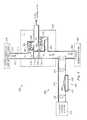
- FIG. 3is a schematic diagram of one possible application of an IOP control system according to one embodiment of the present disclosure.
- the exemplary IOP control system 200includes an electric pump system 400 .
- the electric pump systemcomprises an auxiliary tube 410 and an electric pump mechanism 420 .
- the auxiliary tube 410 and the electric pump mechanism 420provide an alternative pathway for the outflow of aqueous humor through the valve system 220 .
- the auxiliary drainage tube 410is fluidly connected to the drainage tube 210 .
- the auxiliary drainage tube 410runs in a direction substantially perpendicular to the drainage tube 210 .
- operation of the pump mechanism 420can transport aqueous humor that has collected or pooled in or near the primary drainage site 250 to the auxiliary drainage site 370 , thus working to reduce the pressure of pressure area P 2 and causing the outlet valve 320 to open.
- FIG. 5 adepicts a situation of increased flow resistance at the drainage site 250 and thus a likely scenario for pump mechanism activation.
- the pressure at pressure area P 2is elevated.
- Activation and operation of the pump mechanism 420reduces the pressure at the drainage site 250 (P 2 ) such that the outlet valve 320 is forced to open.
- the outflow of aqueous humorideally exits the IOP control system 200 in a direction opposite the anterior chamber 240 and spreads in several directions upon exiting the drainage tubes 210 .
- the systems and methods disclosed hereinprovide a device that a) requires zero to minimal power (internal or external), and b) presents a mechanism of minimizing bleb height (reducing or eliminating bleb) by controlling the flow through the IOP control system 200 based on pressure differentials (and possibly on detected data from a pressure sensor system 500 ), which could significantly reduce the effect of fibrosis and also reduce or eliminate other issues related to bleb management.
Landscapes
- Health & Medical Sciences (AREA)
- Heart & Thoracic Surgery (AREA)
- Life Sciences & Earth Sciences (AREA)
- Veterinary Medicine (AREA)
- Engineering & Computer Science (AREA)
- Biomedical Technology (AREA)
- Public Health (AREA)
- Vascular Medicine (AREA)
- General Health & Medical Sciences (AREA)
- Animal Behavior & Ethology (AREA)
- Ophthalmology & Optometry (AREA)
- Anesthesiology (AREA)
- Hematology (AREA)
- Nuclear Medicine, Radiotherapy & Molecular Imaging (AREA)
- Surgery (AREA)
- External Artificial Organs (AREA)
- Prostheses (AREA)
Abstract
Description
Claims (25)
Priority Applications (1)
| Application Number | Priority Date | Filing Date | Title |
|---|---|---|---|
| US13/315,329US8579848B2 (en) | 2011-12-09 | 2011-12-09 | Active drainage systems with pressure-driven valves and electronically-driven pump |
Applications Claiming Priority (1)
| Application Number | Priority Date | Filing Date | Title |
|---|---|---|---|
| US13/315,329US8579848B2 (en) | 2011-12-09 | 2011-12-09 | Active drainage systems with pressure-driven valves and electronically-driven pump |
Publications (2)
| Publication Number | Publication Date |
|---|---|
| US20130150774A1 US20130150774A1 (en) | 2013-06-13 |
| US8579848B2true US8579848B2 (en) | 2013-11-12 |
Family
ID=48572661
Family Applications (1)
| Application Number | Title | Priority Date | Filing Date |
|---|---|---|---|
| US13/315,329ActiveUS8579848B2 (en) | 2011-12-09 | 2011-12-09 | Active drainage systems with pressure-driven valves and electronically-driven pump |
Country Status (1)
| Country | Link |
|---|---|
| US (1) | US8579848B2 (en) |
Cited By (36)
| Publication number | Priority date | Publication date | Assignee | Title |
|---|---|---|---|---|
| US20130317412A1 (en)* | 2012-05-23 | 2013-11-28 | Bruno Dacquay | Flow Control For Treating A Medical Condition |
| US20160067092A1 (en)* | 2014-09-10 | 2016-03-10 | Novartis Ag | Intraocular pressure sensing system for posterior segment drainage |
| US20160067093A1 (en)* | 2014-09-10 | 2016-03-10 | Novartis Ag | Devices, systems and methods for posterior segment drainage |
| US9295389B2 (en) | 2012-12-17 | 2016-03-29 | Novartis Ag | Systems and methods for priming an intraocular pressure sensor in an intraocular implant |
| US9339187B2 (en) | 2011-12-15 | 2016-05-17 | Alcon Research, Ltd. | External pressure measurement system and method for an intraocular implant |
| US9528633B2 (en) | 2012-12-17 | 2016-12-27 | Novartis Ag | MEMS check valve |
| US9572712B2 (en) | 2012-12-17 | 2017-02-21 | Novartis Ag | Osmotically actuated fluidic valve |
| US9615970B2 (en) | 2009-09-21 | 2017-04-11 | Alcon Research, Ltd. | Intraocular pressure sensor with external pressure compensation |
| US9730638B2 (en) | 2013-03-13 | 2017-08-15 | Glaukos Corporation | Intraocular physiological sensor |
| US10271989B2 (en) | 2012-03-26 | 2019-04-30 | Glaukos Corporation | System and method for delivering multiple ocular implants |
| US10285856B2 (en) | 2001-08-28 | 2019-05-14 | Glaukos Corporation | Implant delivery system and methods thereof for treating ocular disorders |
| US10342702B2 (en) | 2014-08-29 | 2019-07-09 | Camras Vision Inc. | Apparatus and method for reducing intraocular pressure |
| US10369050B2 (en) | 2014-08-29 | 2019-08-06 | Camras Vision Inc. | Device and method for reducing intraocular pressure |
| US10406029B2 (en) | 2001-04-07 | 2019-09-10 | Glaukos Corporation | Ocular system with anchoring implant and therapeutic agent |
| US10485701B2 (en) | 2002-04-08 | 2019-11-26 | Glaukos Corporation | Devices and methods for glaucoma treatment |
| US10485702B2 (en) | 2000-04-14 | 2019-11-26 | Glaukos Corporation | System and method for treating an ocular disorder |
| US10492950B2 (en) | 1999-04-26 | 2019-12-03 | Glaukos Corporation | Shunt device and method for treating ocular disorders |
| US10517759B2 (en) | 2013-03-15 | 2019-12-31 | Glaukos Corporation | Glaucoma stent and methods thereof for glaucoma treatment |
| US10524958B2 (en) | 2015-09-30 | 2020-01-07 | Alievio, Inc. | Method and apparatus for reducing intraocular pressure |
| US10828195B2 (en) | 2006-11-10 | 2020-11-10 | Glaukos Corporation | Uveoscleral shunt and methods for implanting same |
| US10828473B2 (en) | 2001-04-07 | 2020-11-10 | Glaukos Corporation | Ocular implant delivery system and methods thereof |
| US10959941B2 (en) | 2014-05-29 | 2021-03-30 | Glaukos Corporation | Implants with controlled drug delivery features and methods of using same |
| US11116625B2 (en) | 2017-09-28 | 2021-09-14 | Glaukos Corporation | Apparatus and method for controlling placement of intraocular implants |
| WO2021212007A3 (en)* | 2020-04-16 | 2021-11-25 | Shifamed Holdings, Llc | Adjustable glaucoma treatment devices and associated systems and methods |
| US11291585B2 (en) | 2020-02-14 | 2022-04-05 | Shifamed Holdings, Llc | Shunting systems with rotation-based flow control assemblies, and associated systems and methods |
| US11363951B2 (en) | 2011-09-13 | 2022-06-21 | Glaukos Corporation | Intraocular physiological sensor |
| US20220313491A1 (en)* | 2021-04-02 | 2022-10-06 | Twenty Twenty Therapeutics Llc | Passive intraocular pressure control and associated systems, devices, and methods |
| US11517477B2 (en) | 2019-10-10 | 2022-12-06 | Shifamed Holdings, Llc | Adjustable flow glaucoma shunts and associated systems and methods |
| US11529258B2 (en) | 2020-01-23 | 2022-12-20 | Shifamed Holdings, Llc | Adjustable flow glaucoma shunts and associated systems and methods |
| US11737920B2 (en) | 2020-02-18 | 2023-08-29 | Shifamed Holdings, Llc | Adjustable flow glaucoma shunts having non-linearly arranged flow control elements, and associated systems and methods |
| US11766355B2 (en) | 2020-03-19 | 2023-09-26 | Shifamed Holdings, Llc | Intraocular shunts with low-profile actuation elements and associated systems and methods |
| US11865283B2 (en) | 2021-01-22 | 2024-01-09 | Shifamed Holdings, Llc | Adjustable shunting systems with plate assemblies, and associated systems and methods |
| US11925578B2 (en) | 2015-09-02 | 2024-03-12 | Glaukos Corporation | Drug delivery implants with bi-directional delivery capacity |
| US12220350B2 (en) | 2017-07-20 | 2025-02-11 | Shifamed Holdings, Llc | Adjustable flow glaucoma shunts and methods for making and using same |
| US12226343B2 (en) | 2017-07-20 | 2025-02-18 | Shifamed Holdings, Llc | Adjustable flow glaucoma shunts and methods for making and using same |
| US12329682B2 (en) | 2019-01-18 | 2025-06-17 | Shifamed Holdings, Llc | Adjustable flow glaucoma shunts and methods for making and using same |
Families Citing this family (15)
| Publication number | Priority date | Publication date | Assignee | Title |
|---|---|---|---|---|
| WO2012071476A2 (en) | 2010-11-24 | 2012-05-31 | David Haffner | Drug eluting ocular implant |
| WO2010135369A1 (en) | 2009-05-18 | 2010-11-25 | Dose Medical Corporation | Drug eluting ocular implant |
| US10206813B2 (en) | 2009-05-18 | 2019-02-19 | Dose Medical Corporation | Implants with controlled drug delivery features and methods of using same |
| US10245178B1 (en) | 2011-06-07 | 2019-04-02 | Glaukos Corporation | Anterior chamber drug-eluting ocular implant |
| US9592151B2 (en) | 2013-03-15 | 2017-03-14 | Glaukos Corporation | Systems and methods for delivering an ocular implant to the suprachoroidal space within an eye |
| US20150057523A1 (en)* | 2013-08-21 | 2015-02-26 | Alcon Research, Ltd. | Systems and methods for priming an intraocular pressure sensor chamber |
| US20150057594A1 (en) | 2013-08-24 | 2015-02-26 | Alcon Research, Ltd. | Bubble-free microfluidic valve systems and methods |
| US9283114B2 (en) | 2013-08-24 | 2016-03-15 | Novartis Ag | Systems and methods for priming a microfluidic chamber |
| US11564833B2 (en) | 2015-09-25 | 2023-01-31 | Glaukos Corporation | Punctal implants with controlled drug delivery features and methods of using same |
| TWI568408B (en)* | 2015-12-23 | 2017-02-01 | 財團法人工業技術研究院 | Intraocular pressure detecting device and detecting method thereof |
| WO2017122837A1 (en)* | 2016-01-12 | 2017-07-20 | 황규덕 | Intraocular pressure control device including pressure control member |
| CN109937025B (en) | 2016-04-20 | 2022-07-29 | 多斯医学公司 | Delivery device for bioabsorbable ocular drugs |
| DE102017117657A1 (en)* | 2017-08-03 | 2019-02-07 | Carl Zeiss Meditec Ag | Device for influencing an intraocular pressure |
| CN110051892B (en)* | 2019-05-05 | 2021-05-04 | 温州市人民医院 | Full-automatic flow-rate-adjusting backflow-preventing cerebrospinal fluid drainage device |
| CN117563122B (en)* | 2023-12-21 | 2024-07-09 | 燕山大学 | Pressure control valve for blood system and pressure regulating method thereof |
Citations (94)
| Publication number | Priority date | Publication date | Assignee | Title |
|---|---|---|---|---|
| US4089329A (en) | 1976-03-18 | 1978-05-16 | University Of Utah Research Institute | Noninvasive, continuous intraocular pressure monitor |
| US4206762A (en) | 1976-06-21 | 1980-06-10 | Cosman Eric R | Telemetric differential pressure sensing method |
| US4457757A (en) | 1981-07-20 | 1984-07-03 | Molteno Anthony C B | Device for draining aqueous humour |
| US4656827A (en) | 1984-10-17 | 1987-04-14 | Societe Nationale d'Etude et de Construction de Meteur d'Aviation-"S.N.E. C.M.A." | Fuel metering system for a gas turbine engine |
| US4750901A (en) | 1986-03-07 | 1988-06-14 | Molteno Anthony C B | Implant for drainage of aqueous humour |
| US4869282A (en) | 1988-12-09 | 1989-09-26 | Rosemount Inc. | Micromachined valve with polyimide film diaphragm |
| US4922913A (en) | 1987-11-12 | 1990-05-08 | Waters Jr George E | Intraocular pressure sensor |
| US5005577A (en) | 1988-08-23 | 1991-04-09 | Frenkel Ronald E P | Intraocular lens pressure monitoring device |
| US5083742A (en) | 1990-08-01 | 1992-01-28 | Photovac Incorporated | Fluid control valve |
| US5178604A (en) | 1990-05-31 | 1993-01-12 | Iovision, Inc. | Glaucoma implant |
| US5179953A (en) | 1991-08-27 | 1993-01-19 | Jermik Systems, Ltd. | Portable diurnal intraocular pressure recording system |
| US5397300A (en) | 1990-05-31 | 1995-03-14 | Iovision, Inc. | Glaucoma implant |
| US5466233A (en) | 1994-04-25 | 1995-11-14 | Escalon Ophthalmics, Inc. | Tack for intraocular drug delivery and method for inserting and removing same |
| US5476445A (en) | 1990-05-31 | 1995-12-19 | Iovision, Inc. | Glaucoma implant with a temporary flow restricting seal |
| DE4438201A1 (en) | 1994-10-26 | 1996-05-02 | Gerhard Heinrich Dr In Steeger | Intraocular fluid pressure stabilisation device for treating glaucoma |
| US5707643A (en) | 1993-02-26 | 1998-01-13 | Santen Pharmaceutical Co., Ltd. | Biodegradable scleral plug |
| US5910110A (en) | 1995-06-07 | 1999-06-08 | Mentor Ophthalmics, Inc. | Controlling pressure in the eye during surgery |
| US6007511A (en) | 1991-05-08 | 1999-12-28 | Prywes; Arnold S. | Shunt valve and therapeutic delivery system for treatment of glaucoma and methods and apparatus for its installation |
| US6048328A (en) | 1998-02-02 | 2000-04-11 | Medtronic, Inc. | Implantable drug infusion device having an improved valve |
| US20010000527A1 (en) | 1997-11-20 | 2001-04-26 | Optonol Ltd. | Flow regulating implant, method of manufacture, and delivery device |
| US6251090B1 (en) | 1994-12-12 | 2001-06-26 | Robert Logan Avery | Intravitreal medicine delivery |
| US20020019607A1 (en) | 1998-05-21 | 2002-02-14 | Hai Bui | Constant ocular pressure active infusion system |
| US20020049374A1 (en) | 1996-09-04 | 2002-04-25 | Abreu Marcio Marc | Method and apparatus for signal transmission and detection using a contact device |
| US20020099359A1 (en) | 2001-01-09 | 2002-07-25 | Santini John T. | Flexible microchip devices for ophthalmic and other applications |
| US6447449B1 (en) | 2000-08-21 | 2002-09-10 | Cleveland Clinic Foundation | System for measuring intraocular pressure of an eye and a MEM sensor for use therewith |
| US20020139947A1 (en) | 2000-04-20 | 2002-10-03 | Wang Tak Kui | Extended range diaphragm valve and method for making same |
| US20020143284A1 (en) | 2001-04-03 | 2002-10-03 | Hosheng Tu | Drug-releasing trabecular implant for glaucoma treatment |
| US6468283B1 (en) | 1995-05-14 | 2002-10-22 | Optonol, Ltd. | Method of regulating pressure with an intraocular implant |
| US20020193674A1 (en) | 2000-08-21 | 2002-12-19 | The Cleveland Clinic Foundation | Measurement system including a sensor mounted in a contact lens |
| US20030014036A1 (en) | 2001-06-12 | 2003-01-16 | Varner Signe Erickson | Reservoir device for intraocular drug delivery |
| US20030078487A1 (en) | 2001-08-09 | 2003-04-24 | Jeffries Robert E. | Ocular pressure measuring device |
| US6579235B1 (en) | 1999-11-01 | 2003-06-17 | The Johns Hopkins University | Method for monitoring intraocular pressure using a passive intraocular pressure sensor and patient worn monitoring recorder |
| US6589198B1 (en) | 1998-01-29 | 2003-07-08 | David Soltanpour | Implantable micro-pump assembly |
| US20030225318A1 (en) | 2002-05-31 | 2003-12-04 | Valentino Montegrande | Intraocular pressure sensor |
| US6682500B2 (en) | 1998-01-29 | 2004-01-27 | David Soltanpour | Synthetic muscle based diaphragm pump apparatuses |
| US20040059248A1 (en) | 2001-01-17 | 2004-03-25 | Arthur Messner | Implant for determining intra-ocular pressure |
| US6712764B2 (en) | 1999-02-08 | 2004-03-30 | Robert E. Jeffries | Intraocular pressure monitoring/measuring apparatus and method |
| US6719750B2 (en) | 2000-08-30 | 2004-04-13 | The Johns Hopkins University | Devices for intraocular drug delivery |
| US20040073137A1 (en) | 2002-08-27 | 2004-04-15 | Board Of Trustees Of Michigan State University | Implantable microscale pressure sensor system for pressure monitoring and management |
| US20040111050A1 (en) | 2000-04-14 | 2004-06-10 | Gregory Smedley | Implantable ocular pump to reduce intraocular pressure |
| US20040116794A1 (en) | 2002-10-16 | 2004-06-17 | Wolfgang Fink | Optically powered and optically data-transmitting wireless intraocular pressure sensor device |
| US20040186367A1 (en) | 2001-05-11 | 2004-09-23 | Fresco Bernard B. | Dual tonometer |
| US20040254438A1 (en) | 2003-01-09 | 2004-12-16 | The Regents Of The University Of California | Implantable devices and methods for measuring intraocular, subconjunctival or subdermal pressure and/or analyte concentration |
| US20040254517A1 (en) | 2003-02-18 | 2004-12-16 | Hugo Quiroz-Mercado | Methods and devices for draining fluids and lowering intraocular pressure |
| US20050049578A1 (en) | 2000-04-14 | 2005-03-03 | Hosheng Tu | Implantable ocular pump to reduce intraocular pressure |
| US20050159660A1 (en) | 2002-05-31 | 2005-07-21 | Valentino Montegrande | Intraocular pressure sensor |
| US6939299B1 (en) | 1999-12-13 | 2005-09-06 | Kurt Petersen | Implantable continuous intraocular pressure sensor |
| WO2005088417A1 (en) | 2004-03-12 | 2005-09-22 | Hengst Gmbh & Co. Kg | Pneumatic pressure regulation valve |
| US20050273033A1 (en) | 2002-05-29 | 2005-12-08 | Grahn Bruce H | Shunt and method treatment of glaucoma |
| US20050271704A1 (en) | 2002-04-08 | 2005-12-08 | Hosheng Tu | Injectable glaucoma implants with multiple openings |
| US20060131350A1 (en) | 2004-12-22 | 2006-06-22 | Schechter Alan M | Apparatus for dispensing pressurized contents |
| US7137952B2 (en) | 2001-06-29 | 2006-11-21 | Ecole Polytechnique Federale De Lausanne-Service Des Relations Industrielles | Intraocular pressure recording system |
| US20070019156A1 (en) | 2005-07-15 | 2007-01-25 | California Institute Of Technology | Optomechanical and digital ocular sensor reader systems |
| US20070032757A1 (en) | 2003-09-09 | 2007-02-08 | Medow Joshua E | Medical shunt/valve for regulation of bodily fluids |
| US20070077270A1 (en) | 2005-03-28 | 2007-04-05 | Clemson University | Delivery devices and methods for long-term, targeted delivery of therapeutic agents to the eye and ear |
| US20070106199A1 (en) | 1998-01-29 | 2007-05-10 | Daniel Krivoy | Implantable pump apparatuses |
| US20070109117A1 (en) | 2005-11-14 | 2007-05-17 | Edwards Lifesciences Corporation | Wireless communication protocol for a medical sensor system |
| US20070123767A1 (en) | 2002-05-31 | 2007-05-31 | Valentino Montegrande | Intraocular pressure sensor and method of use |
| US7252006B2 (en) | 2004-06-07 | 2007-08-07 | California Institute Of Technology | Implantable mechanical pressure sensor and method of manufacturing the same |
| US20070212397A1 (en) | 2005-09-15 | 2007-09-13 | Roth Daniel B | Pharmaceutical delivery device and method for providing ocular treatment |
| WO2007127305A2 (en) | 2006-04-26 | 2007-11-08 | Eastern Virginia Medical School | Systems and methods for monitoring and controlling internal pressure of an eye or body part |
| US20080015421A1 (en) | 2000-10-16 | 2008-01-17 | Remon Medical Technologies, Ltd. | Barometric pressure correction based on remote sources of information |
| US20080027478A1 (en)* | 2000-04-14 | 2008-01-31 | Connors Kevin G | Methods for attenuating pressure waves in a patient's eye |
| US20080077127A1 (en) | 2006-09-27 | 2008-03-27 | Gao Shawn X | Intraocular pressure control |
| US20080097276A1 (en) | 2004-07-20 | 2008-04-24 | Medtronic, Inc. | Implantable cerebral spinal fluid drainage system |
| WO2008061043A2 (en) | 2006-11-10 | 2008-05-22 | Glaukos Corporation | Uveoscleral shunt and methods for implanting same |
| US20080129486A1 (en) | 2005-04-26 | 2008-06-05 | Joel Jeckelmann | Energy-Optimised Data Transmission for a Medical Appliance |
| US20080147021A1 (en) | 2006-12-15 | 2008-06-19 | Jani Dharmendra M | Drug delivery devices |
| US7409863B2 (en) | 2004-10-05 | 2008-08-12 | Sensata Technologies Maryland, Inc. | Pressure sensor |
| WO2008084350A3 (en) | 2007-01-08 | 2008-10-23 | Consejo Nac Invest Cient Tec | Implantable ocular microapparatus to ameliorate glaucoma or an ocular overpressure causing disease |
| WO2009010799A2 (en) | 2007-07-17 | 2009-01-22 | Sheppard & Charnley Limited | Electric motor/generator assembly |
| US20090069648A1 (en) | 2007-08-23 | 2009-03-12 | Purdue Research Foundation | Intra-occular pressure sensor |
| US20090076367A1 (en) | 2006-05-17 | 2009-03-19 | Mayo Foundation For Medical Education And Research | Monitoring Intraocular Pressure |
| US20090143713A1 (en) | 2007-11-30 | 2009-06-04 | Jacques Van Dam | Biliary Shunts, Delivery Systems, Methods of Using the Same and Kits Therefor |
| US20090227933A1 (en) | 2003-02-18 | 2009-09-10 | S.K. Pharmaceuticals | Optic nerve implants |
| US20090240215A1 (en) | 2007-12-20 | 2009-09-24 | Mark Humayun | Apparatus and methods for delivering therapeutic agents |
| US7612328B2 (en) | 2005-07-11 | 2009-11-03 | Iee International Electronics & Engineering S.A. | Foil-type pressure sensor |
| US20090312742A1 (en) | 2008-05-08 | 2009-12-17 | Changlin Pang | Drug-delivery pumps and methods of manufacture |
| US20100010416A1 (en) | 2006-01-17 | 2010-01-14 | Juan Jr Eugene De | Glaucoma treatment device |
| US20100121348A1 (en) | 2008-11-12 | 2010-05-13 | Ross Creek Medical | Insertion tool for knotless suture anchor for soft tissue repair and method of use |
| US20100174272A1 (en) | 2009-01-02 | 2010-07-08 | Weiner Alan L | In-situ refillable ophthalmic implant |
| US7756559B2 (en) | 1996-09-04 | 2010-07-13 | Marcio Marc Abreu | Device for generating a detectable signal based upon antibody/antigen interaction |
| US20100222769A1 (en) | 2009-02-20 | 2010-09-02 | University Of Southern California | Mems electrochemical bellows actuator |
| US20100234717A1 (en) | 2007-10-19 | 2010-09-16 | Sensimed Ag | Intraocular Pressure Monitoring Device |
| WO2010129446A1 (en) | 2009-05-04 | 2010-11-11 | Alcon Research, Ltd. | Intraocular pressure sensor |
| US20100305550A1 (en) | 2006-03-14 | 2010-12-02 | Ellis Meng | Mems device and method for delivery of therapeutic agents |
| US20110046536A1 (en) | 2009-08-20 | 2011-02-24 | Grieshaber Ophthalmic Research Foundation | Method and device for the treatment of glaucoma |
| WO2011034742A2 (en) | 2009-09-21 | 2011-03-24 | Alcon Research, Ltd. | Glaucoma drainage device with pump |
| WO2011034740A1 (en) | 2009-09-21 | 2011-03-24 | Alcon Research, Ltd. | Power saving glaucoma drainage device |
| US20110071454A1 (en) | 2009-09-21 | 2011-03-24 | Alcon Research, Ltd. | Power Generator For Glaucoma Drainage Device |
| US20110071456A1 (en) | 2009-09-21 | 2011-03-24 | Rickard Matthew J A | Lumen Clearing Valve For Glaucoma Drainage Device |
| US20110071505A1 (en) | 2009-09-21 | 2011-03-24 | Matthew Rickard | Intraocular Pressure Sensor with External Pressure Compensation |
| US20110248671A1 (en) | 2010-04-08 | 2011-10-13 | Alcon Research, Ltd. | Power System Implantable in Eye |
| WO2012012017A1 (en) | 2010-07-20 | 2012-01-26 | Alcon Research, Ltd. | Closed loop glaucoma drug delivery system |
- 2011
- 2011-12-09USUS13/315,329patent/US8579848B2/enactiveActive
Patent Citations (112)
| Publication number | Priority date | Publication date | Assignee | Title |
|---|---|---|---|---|
| US4089329A (en) | 1976-03-18 | 1978-05-16 | University Of Utah Research Institute | Noninvasive, continuous intraocular pressure monitor |
| US4206762A (en) | 1976-06-21 | 1980-06-10 | Cosman Eric R | Telemetric differential pressure sensing method |
| US4457757A (en) | 1981-07-20 | 1984-07-03 | Molteno Anthony C B | Device for draining aqueous humour |
| US4656827A (en) | 1984-10-17 | 1987-04-14 | Societe Nationale d'Etude et de Construction de Meteur d'Aviation-"S.N.E. C.M.A." | Fuel metering system for a gas turbine engine |
| US4750901A (en) | 1986-03-07 | 1988-06-14 | Molteno Anthony C B | Implant for drainage of aqueous humour |
| US4922913A (en) | 1987-11-12 | 1990-05-08 | Waters Jr George E | Intraocular pressure sensor |
| US5005577A (en) | 1988-08-23 | 1991-04-09 | Frenkel Ronald E P | Intraocular lens pressure monitoring device |
| US4869282A (en) | 1988-12-09 | 1989-09-26 | Rosemount Inc. | Micromachined valve with polyimide film diaphragm |
| US5178604A (en) | 1990-05-31 | 1993-01-12 | Iovision, Inc. | Glaucoma implant |
| US5397300A (en) | 1990-05-31 | 1995-03-14 | Iovision, Inc. | Glaucoma implant |
| US5476445A (en) | 1990-05-31 | 1995-12-19 | Iovision, Inc. | Glaucoma implant with a temporary flow restricting seal |
| US5558629A (en) | 1990-05-31 | 1996-09-24 | Iovision, Inc. | Glaucoma implant |
| US5083742A (en) | 1990-08-01 | 1992-01-28 | Photovac Incorporated | Fluid control valve |
| US6007511A (en) | 1991-05-08 | 1999-12-28 | Prywes; Arnold S. | Shunt valve and therapeutic delivery system for treatment of glaucoma and methods and apparatus for its installation |
| US5179953A (en) | 1991-08-27 | 1993-01-19 | Jermik Systems, Ltd. | Portable diurnal intraocular pressure recording system |
| US5707643A (en) | 1993-02-26 | 1998-01-13 | Santen Pharmaceutical Co., Ltd. | Biodegradable scleral plug |
| US5466233A (en) | 1994-04-25 | 1995-11-14 | Escalon Ophthalmics, Inc. | Tack for intraocular drug delivery and method for inserting and removing same |
| DE4438201A1 (en) | 1994-10-26 | 1996-05-02 | Gerhard Heinrich Dr In Steeger | Intraocular fluid pressure stabilisation device for treating glaucoma |
| US6251090B1 (en) | 1994-12-12 | 2001-06-26 | Robert Logan Avery | Intravitreal medicine delivery |
| US6468283B1 (en) | 1995-05-14 | 2002-10-22 | Optonol, Ltd. | Method of regulating pressure with an intraocular implant |
| US5910110A (en) | 1995-06-07 | 1999-06-08 | Mentor Ophthalmics, Inc. | Controlling pressure in the eye during surgery |
| US7756559B2 (en) | 1996-09-04 | 2010-07-13 | Marcio Marc Abreu | Device for generating a detectable signal based upon antibody/antigen interaction |
| US20020049374A1 (en) | 1996-09-04 | 2002-04-25 | Abreu Marcio Marc | Method and apparatus for signal transmission and detection using a contact device |
| US20080125691A1 (en) | 1997-11-20 | 2008-05-29 | Optonol Ltd. | Flow regulating implants |
| US20010000527A1 (en) | 1997-11-20 | 2001-04-26 | Optonol Ltd. | Flow regulating implant, method of manufacture, and delivery device |
| US6589198B1 (en) | 1998-01-29 | 2003-07-08 | David Soltanpour | Implantable micro-pump assembly |
| US20070106199A1 (en) | 1998-01-29 | 2007-05-10 | Daniel Krivoy | Implantable pump apparatuses |
| US6682500B2 (en) | 1998-01-29 | 2004-01-27 | David Soltanpour | Synthetic muscle based diaphragm pump apparatuses |
| US6048328A (en) | 1998-02-02 | 2000-04-11 | Medtronic, Inc. | Implantable drug infusion device having an improved valve |
| US20020019607A1 (en) | 1998-05-21 | 2002-02-14 | Hai Bui | Constant ocular pressure active infusion system |
| US6712764B2 (en) | 1999-02-08 | 2004-03-30 | Robert E. Jeffries | Intraocular pressure monitoring/measuring apparatus and method |
| US6579235B1 (en) | 1999-11-01 | 2003-06-17 | The Johns Hopkins University | Method for monitoring intraocular pressure using a passive intraocular pressure sensor and patient worn monitoring recorder |
| US6939299B1 (en) | 1999-12-13 | 2005-09-06 | Kurt Petersen | Implantable continuous intraocular pressure sensor |
| US20050049578A1 (en) | 2000-04-14 | 2005-03-03 | Hosheng Tu | Implantable ocular pump to reduce intraocular pressure |
| US20080027478A1 (en)* | 2000-04-14 | 2008-01-31 | Connors Kevin G | Methods for attenuating pressure waves in a patient's eye |
| US20040111050A1 (en) | 2000-04-14 | 2004-06-10 | Gregory Smedley | Implantable ocular pump to reduce intraocular pressure |
| US20020139947A1 (en) | 2000-04-20 | 2002-10-03 | Wang Tak Kui | Extended range diaphragm valve and method for making same |
| US20070129623A1 (en) | 2000-08-21 | 2007-06-07 | The Cleveland Clinic Foundation | Intraocular pressure measurement system including a sensor mounted in a contact lens |
| US20020193674A1 (en) | 2000-08-21 | 2002-12-19 | The Cleveland Clinic Foundation | Measurement system including a sensor mounted in a contact lens |
| US6749568B2 (en) | 2000-08-21 | 2004-06-15 | Cleveland Clinic Foundation | Intraocular pressure measurement system including a sensor mounted in a contact lens |
| US6447449B1 (en) | 2000-08-21 | 2002-09-10 | Cleveland Clinic Foundation | System for measuring intraocular pressure of an eye and a MEM sensor for use therewith |
| US7169106B2 (en) | 2000-08-21 | 2007-01-30 | The Cleveland Clinic Foundation | Intraocular pressure measurement system including a sensor mounted in a contact lens |
| US6719750B2 (en) | 2000-08-30 | 2004-04-13 | The Johns Hopkins University | Devices for intraocular drug delivery |
| US20080015421A1 (en) | 2000-10-16 | 2008-01-17 | Remon Medical Technologies, Ltd. | Barometric pressure correction based on remote sources of information |
| US20020099359A1 (en) | 2001-01-09 | 2002-07-25 | Santini John T. | Flexible microchip devices for ophthalmic and other applications |
| US6976982B2 (en) | 2001-01-09 | 2005-12-20 | Microchips, Inc. | Flexible microchip devices for ophthalmic and other applications |
| US20040059248A1 (en) | 2001-01-17 | 2004-03-25 | Arthur Messner | Implant for determining intra-ocular pressure |
| US20020143284A1 (en) | 2001-04-03 | 2002-10-03 | Hosheng Tu | Drug-releasing trabecular implant for glaucoma treatment |
| US20040186367A1 (en) | 2001-05-11 | 2004-09-23 | Fresco Bernard B. | Dual tonometer |
| US20030014036A1 (en) | 2001-06-12 | 2003-01-16 | Varner Signe Erickson | Reservoir device for intraocular drug delivery |
| US7137952B2 (en) | 2001-06-29 | 2006-11-21 | Ecole Polytechnique Federale De Lausanne-Service Des Relations Industrielles | Intraocular pressure recording system |
| US20030078487A1 (en) | 2001-08-09 | 2003-04-24 | Jeffries Robert E. | Ocular pressure measuring device |
| US20050271704A1 (en) | 2002-04-08 | 2005-12-08 | Hosheng Tu | Injectable glaucoma implants with multiple openings |
| US20050273033A1 (en) | 2002-05-29 | 2005-12-08 | Grahn Bruce H | Shunt and method treatment of glaucoma |
| US20050159660A1 (en) | 2002-05-31 | 2005-07-21 | Valentino Montegrande | Intraocular pressure sensor |
| US20070123767A1 (en) | 2002-05-31 | 2007-05-31 | Valentino Montegrande | Intraocular pressure sensor and method of use |
| US20030225318A1 (en) | 2002-05-31 | 2003-12-04 | Valentino Montegrande | Intraocular pressure sensor |
| US20040073137A1 (en) | 2002-08-27 | 2004-04-15 | Board Of Trustees Of Michigan State University | Implantable microscale pressure sensor system for pressure monitoring and management |
| US20040116794A1 (en) | 2002-10-16 | 2004-06-17 | Wolfgang Fink | Optically powered and optically data-transmitting wireless intraocular pressure sensor device |
| US20040254438A1 (en) | 2003-01-09 | 2004-12-16 | The Regents Of The University Of California | Implantable devices and methods for measuring intraocular, subconjunctival or subdermal pressure and/or analyte concentration |
| US7354416B2 (en) | 2003-02-18 | 2008-04-08 | Hugo Quiroz-Mercado | Methods and devices for draining fluids and lowering intraocular pressure |
| US20040254517A1 (en) | 2003-02-18 | 2004-12-16 | Hugo Quiroz-Mercado | Methods and devices for draining fluids and lowering intraocular pressure |
| US20090227933A1 (en) | 2003-02-18 | 2009-09-10 | S.K. Pharmaceuticals | Optic nerve implants |
| US20070032757A1 (en) | 2003-09-09 | 2007-02-08 | Medow Joshua E | Medical shunt/valve for regulation of bodily fluids |
| WO2005088417A1 (en) | 2004-03-12 | 2005-09-22 | Hengst Gmbh & Co. Kg | Pneumatic pressure regulation valve |
| US7252006B2 (en) | 2004-06-07 | 2007-08-07 | California Institute Of Technology | Implantable mechanical pressure sensor and method of manufacturing the same |
| US20080097276A1 (en) | 2004-07-20 | 2008-04-24 | Medtronic, Inc. | Implantable cerebral spinal fluid drainage system |
| US7409863B2 (en) | 2004-10-05 | 2008-08-12 | Sensata Technologies Maryland, Inc. | Pressure sensor |
| US20060131350A1 (en) | 2004-12-22 | 2006-06-22 | Schechter Alan M | Apparatus for dispensing pressurized contents |
| US20070077270A1 (en) | 2005-03-28 | 2007-04-05 | Clemson University | Delivery devices and methods for long-term, targeted delivery of therapeutic agents to the eye and ear |
| US20080129486A1 (en) | 2005-04-26 | 2008-06-05 | Joel Jeckelmann | Energy-Optimised Data Transmission for a Medical Appliance |
| US7612328B2 (en) | 2005-07-11 | 2009-11-03 | Iee International Electronics & Engineering S.A. | Foil-type pressure sensor |
| US20070019156A1 (en) | 2005-07-15 | 2007-01-25 | California Institute Of Technology | Optomechanical and digital ocular sensor reader systems |
| US20070212397A1 (en) | 2005-09-15 | 2007-09-13 | Roth Daniel B | Pharmaceutical delivery device and method for providing ocular treatment |
| US20070109117A1 (en) | 2005-11-14 | 2007-05-17 | Edwards Lifesciences Corporation | Wireless communication protocol for a medical sensor system |
| US20100010416A1 (en) | 2006-01-17 | 2010-01-14 | Juan Jr Eugene De | Glaucoma treatment device |
| US20100305550A1 (en) | 2006-03-14 | 2010-12-02 | Ellis Meng | Mems device and method for delivery of therapeutic agents |
| WO2007127305A2 (en) | 2006-04-26 | 2007-11-08 | Eastern Virginia Medical School | Systems and methods for monitoring and controlling internal pressure of an eye or body part |
| US20090275924A1 (en) | 2006-04-26 | 2009-11-05 | Eastern Virginia Medical School | Systems and Methods for Monitoring and Controlling Internal Pressure of an Eye or Body Part |
| US20090076367A1 (en) | 2006-05-17 | 2009-03-19 | Mayo Foundation For Medical Education And Research | Monitoring Intraocular Pressure |
| US20080077127A1 (en) | 2006-09-27 | 2008-03-27 | Gao Shawn X | Intraocular pressure control |
| WO2008061043A2 (en) | 2006-11-10 | 2008-05-22 | Glaukos Corporation | Uveoscleral shunt and methods for implanting same |
| US20080228127A1 (en) | 2006-11-10 | 2008-09-18 | Glaukos Corporation | Uveoscleral shunt and methods for implanting same |
| US20080147021A1 (en) | 2006-12-15 | 2008-06-19 | Jani Dharmendra M | Drug delivery devices |
| US20100042209A1 (en) | 2007-01-08 | 2010-02-18 | Fabio Ariel Guarnieri | Implantable ocular microapparatus to ameliorate glaucoma or an ocular overpressure causing disease |
| WO2008084350A3 (en) | 2007-01-08 | 2008-10-23 | Consejo Nac Invest Cient Tec | Implantable ocular microapparatus to ameliorate glaucoma or an ocular overpressure causing disease |
| US20100253167A1 (en) | 2007-07-17 | 2010-10-07 | Sheppard & Charnley Limited | Electric motor/generator assembly |
| WO2009010799A2 (en) | 2007-07-17 | 2009-01-22 | Sheppard & Charnley Limited | Electric motor/generator assembly |
| US20090069648A1 (en) | 2007-08-23 | 2009-03-12 | Purdue Research Foundation | Intra-occular pressure sensor |
| US20100234717A1 (en) | 2007-10-19 | 2010-09-16 | Sensimed Ag | Intraocular Pressure Monitoring Device |
| US20090143713A1 (en) | 2007-11-30 | 2009-06-04 | Jacques Van Dam | Biliary Shunts, Delivery Systems, Methods of Using the Same and Kits Therefor |
| US20090240215A1 (en) | 2007-12-20 | 2009-09-24 | Mark Humayun | Apparatus and methods for delivering therapeutic agents |
| US20090312742A1 (en) | 2008-05-08 | 2009-12-17 | Changlin Pang | Drug-delivery pumps and methods of manufacture |
| US20100121348A1 (en) | 2008-11-12 | 2010-05-13 | Ross Creek Medical | Insertion tool for knotless suture anchor for soft tissue repair and method of use |
| US20100174272A1 (en) | 2009-01-02 | 2010-07-08 | Weiner Alan L | In-situ refillable ophthalmic implant |
| US20100222769A1 (en) | 2009-02-20 | 2010-09-02 | University Of Southern California | Mems electrochemical bellows actuator |
| EP2427097A1 (en) | 2009-05-04 | 2012-03-14 | Alcon Research, Ltd. | Intraocular pressure sensor |
| WO2010129446A1 (en) | 2009-05-04 | 2010-11-11 | Alcon Research, Ltd. | Intraocular pressure sensor |
| US8182435B2 (en) | 2009-05-04 | 2012-05-22 | Alcon Research, Ltd. | Intraocular pressure sensor |
| US20110046536A1 (en) | 2009-08-20 | 2011-02-24 | Grieshaber Ophthalmic Research Foundation | Method and device for the treatment of glaucoma |
| US20110071454A1 (en) | 2009-09-21 | 2011-03-24 | Alcon Research, Ltd. | Power Generator For Glaucoma Drainage Device |
| US20110071456A1 (en) | 2009-09-21 | 2011-03-24 | Rickard Matthew J A | Lumen Clearing Valve For Glaucoma Drainage Device |
| US20110071505A1 (en) | 2009-09-21 | 2011-03-24 | Matthew Rickard | Intraocular Pressure Sensor with External Pressure Compensation |
| WO2011034727A1 (en) | 2009-09-21 | 2011-03-24 | Alcon Research, Ltd. | Intraocular pressure sensor with external pressure compensation |
| WO2011034738A1 (en) | 2009-09-21 | 2011-03-24 | Alcon Research, Ltd. | Power generator for glaucoma drainage device |
| WO2011035218A1 (en) | 2009-09-21 | 2011-03-24 | Alcon Research, Ltd. | Lumen clearing valve for glaucoma drainage device |
| WO2011034740A1 (en) | 2009-09-21 | 2011-03-24 | Alcon Research, Ltd. | Power saving glaucoma drainage device |
| WO2011034742A2 (en) | 2009-09-21 | 2011-03-24 | Alcon Research, Ltd. | Glaucoma drainage device with pump |
| US8257295B2 (en) | 2009-09-21 | 2012-09-04 | Alcon Research, Ltd. | Intraocular pressure sensor with external pressure compensation |
| US8419673B2 (en) | 2009-09-21 | 2013-04-16 | Alcon Research, Ltd. | Glaucoma drainage device with pump |
| US20110248671A1 (en) | 2010-04-08 | 2011-10-13 | Alcon Research, Ltd. | Power System Implantable in Eye |
| WO2012012017A1 (en) | 2010-07-20 | 2012-01-26 | Alcon Research, Ltd. | Closed loop glaucoma drug delivery system |
Non-Patent Citations (43)
| Title |
|---|
| "Walter, Peter; Intraocular Pressure Sensor: Where Are We-Where Will We Go? Journal Graefe's Archive for Clinical and Experimental Ophthalmology; Publisher Springer Berline/Heidelberg; ISSN 0721-832X (Print) 1435-702X (Online); Issue vol. 240, No. 5/May 2002 DOI 10.1007/s00417-002-0474-gamma; pp. 335-336; Subject Collection Medicine." |
| "Walter, Peter; Intraocular Pressure Sensor: Where Are We—Where Will We Go? Journal Graefe's Archive for Clinical and Experimental Ophthalmology; Publisher Springer Berline/Heidelberg; ISSN 0721-832X (Print) 1435-702X (Online); Issue vol. 240, No. 5/May 2002 DOI 10.1007/s00417-002-0474-γ; pp. 335-336; Subject Collection Medicine." |
| Byunghoon Bae, Hongseok Kee, Seonho Kim, Yeon Lee, Taeseok Sim, Yongkweon Him and Kyihwan Park; "In Vitro Experiment of the Pressure Regulating Valve for a Glaucoma Impact"; Journal of Micromechanics and Microengineering, 13 (2003); pp. 613-619. |
| Driot et al.; "Ocular pharmacokinetics of fluocinolone acetonide after RetisertTM intravitreal implantation in rabbits over a 1-year period"; J. Ocular Pharm; vol. 20; No. 3; pp. 269-275 (2004). |
| Eggers, T., et al, "Wireless Intra-Ocular Pressure Monitoring System Integrated Into an Artificial Lens," 1st Annual Int'l IEEE-EMBS Special Topic Conference on Microtechnologies in Medicine & Biology, Oct. 12-14, 2000, pp. 466-469, Lyon, France. |
| Erik Stemme and Goran Stemme; "A Valveless Diffuser/Nozzle-Based Fluid Pump"; ScienceDirect; Sensors and Actuators A, 39 (1993); pp. 159-167. |
| Glybina et al.; "Neuroprotective properties of fluocinolone acetonide chronically delivered into the vitreous of albino RCS rats"; IVOS; vol. 47; ARVO E-Abstract 1028 (2006). |
| Greene, M.E. and Gilman, B.G., "Intraocular Pressure Measurement With Instrumented Contact Lenses," Investigative Ophthalmology & Visual Science (IVOS), Apr. 1974, pp. 299-302, vol. 13, No. 4, IVOS. |
| Hjortdal, Jesper and Jensen, Peter, "In Vitro Measurement of Corneal Strain, Thickness, and Curvature Using Digital Image Processing," Acta Ophthalmologica Scandinavica, 1995, pp. 5-11, vol. 73, Denmark. |
| International Search Report and Written Opinion corresponding to PCT/US2010/047605 dated Dec. 16, 2010. |
| International Search Report and Written Opinion corresponding to PCT/US2010/047612 dated Dec. 21, 2010. |
| International Search Report and Written Opinion corresponding to PCT/US2012/067747 dated Apr. 2, 2013. |
| International Search Report and Written Opinion corresponding to PCT/US2012/068878 dated Apr. 3, 2013. |
| International Searching Authority, Invitation to Pay Additional Fees and, Where Applicable, Protest Fee (Partial Search Report attached), PCT/US2012/067741, Apr. 2, 2013, 6 pages. |
| International Searching Authority, Search Report and Written Opinion of the International Searching Authority, PCT/US2010/033329, Jul. 13, 2010, 14 pages. |
| International Searching Authority, Search Report and Written Opinion of the International Searching Authority, PCT/US2010/047429, Nov. 1, 2010, 15 pages. |
| International Searching Authority, Search Report and Written Opinion of the International Searching Authority, PCT/US2010/047600, Dec. 14, 2010, 13 pages. |
| International Searching Authority, Search Report and Written Opinion of the International Searching Authority, PCT/US2010/049424, Nov. 26, 2010, 15 pages. |
| International Searching Authority, Search Report of the International Searching Authority, PCT/US2011/036742, Aug. 17, 2011, 2 pages. |
| Kupperman et al.; "Efficacy and safety of a novel intravitreous dexamethasone drug-delivery system after applicator or incisional placement in patients with macular edema"; IVOS; vol. 47; ARVO E-Abstract 5913 (2006). |
| Lam, Andrew K.C. and Douthwaite, William A., "The Effect of an Artificially Elevated Intraocular Pressure on the Central Corneal Curvature," Ophthalmic and Physiological Optics, 1997, pp. 18-24, vol. 17, No. 1, Elsevier Science, Ltd., Great Britain. |
| Leonardi, Matteo, et al., "A Soft Contact Lens With a Mems Strain Gage Embedded for Intraocular Pressure Monitoring," In Proc. 12th Int'l Conference on Solid State Sensors, Actuators and Microsystems, Jun. 8-12, 2003, pp. 1043-1046, vol. 2, Boston, MA. |
| Leonardi, Matteo, et al., "First Steps Toward Noninvasive Intraocular Pressure Monitoring with a Sensing Contact Lens," Investigative Ophthalmology & Visual Science (IVOS), 2004, pp. 3113-3117, vol. 45, No. 9, IVOS. |
| McLaren, Jay W., et al, "Continuous Measurement of Intraocular Pressure in Rabbits by Telemetry," Investigative Ophthalmology & Visual Science (IVOS), May 1996, pp. 966-975, vol. 37, No. 6, IVOS. |
| Miruthyunjaya et al.; "An intravitreal sustained release fluocinolone acetonide device to treat severe experimental uveitis"; IVOS; vol. 44; ARVO E-Abstract 4215 (2003). |
| Miyamoto et al.; "Biodegradable scleral implant for intravitreal controlled release of fluconazole"; Current Eye Res.; vol. 16; No. 19; pp. 930-935 (1997). |
| Mokwa, Wilfried, et al, "Micro-Transponder Systems for Medical Applications," IEEE Transactions on Instrumentation and Measurement, Dec. 2001, pp. 1551-1555, vol. 50, No. 6, IEEE, Germany. |
| Neagu Cristina R.; "A Medical Microactuator Based on an Electrochemical Principle"; Thesis at the Twente University,the Netherlands, Enschede; Aug. 28, 1998; pp. 1-162. |
| Nisar A., Afzulpurkar Nitin, Mahaisavariya Banchong, and Tuantranont Adisorn; "MEMS-Based Micropumps in Drug Delivery and Biomedical Applications"; ScienceDirect; Sensors and Actuators B 130 (2008) pp. 917-942. |
| Puers, Robert, "Linking Sensors with Telemetry: Impact on the System Design," in Proc. 8th Int'l Conference of Solid State Sensors, Actuators, Eurosens, Jun. 25-29, 1995, pp. 169-174, Stockholm, Sweden. |
| Ratanapakorin et al.; "Helical intravitreal triamcinolone implant: An explanation survival study"; IVOS; vol. 46; ARVO E-Abstract 484 (2005). |
| Rego et al; "In vitro evaluation of sustained-release intravitreal dexamethasone implants"; IVOS; vol. 45; ARVO E-Abstract 5060 (2004). |
| Sakurai et al.; "Scleral plug of biodegradable polymers containing ganciclovir for experimental cytomegalovirus retinitis"; IVOS; vol. 42; No. 9; pp. 2043-2048 (2004). |
| Saloomeh Saati MD., Ronalee Lo PhD, Po-Ying Li PhD, Ellis Meng PhD, Rohit Varma MD MPH, and Mark S. Humayun MD PhD; "Mini Drug Pump for Ophthalmic Use"; Trans Am Ophthalmol Soc 2009; 107; pp. 60-71. |
| Schnakenberg, U., et al, "Initial Investigations on Systems for Measuring Intraocular Pressure," Sensors and Actuators, 2000, p. 287-291, vol. 85, Elsevier Science B.V., Germany. |
| See et al.; "Safety and drug release profile of injectable intravitreal sustained-release fluocinolone acetonide device"; IVOS; vol. 47; ARVO E-Abstract 5119 (2006). |
| Stangel, Karsten, et al, "A Programmable Intraocular CMOS Pressure Sensor System Implant," IEEE Journal of Solid-State Circuits, Jul. 2001, pp. 1094-1100, vol. 36, No. 7, IEEE, Germany. |
| Tano et al.; "Helical intravitreal implant: surgical method development and outcomes"; IVOS; vol. 46; ARVO E-Abstract 483 (2005). |
| Ullerich, Stella, et al, "Micro Coils for an Advanced System for Measuring Intraocular Pressure," 1st Annual Int'l IEEE-EMBS Special Topic Conference on Microtechnologies in Medicine & Biology, Oct. 12-14, 2000, pp. 470-474, Lyon, France. |
| Van Schuylenbergh, K., et al, "An Implantable Telemetric Tonometer for Direct Intraocular Pressure Measurements," 1st European Conference on Biomedical Engineering, Feb. 1991, pp. 194-195, vol. 17, No. 20, Nice, France. |
| Varner et al.; "Development of a minimally invasive intravitreal implant for drug delivery"; IVOS; vol. 44; ARVO E-Abstract 4214 (2003). |
| Weiner; "Drug delivery systems in ophthalmic applications; In Ocular Therapeutics; Eye on New Discoveries; T. Yorio, A. Clark, M. Wax, Eds, Elsevier Press/Academic Press, New York", pp. 7-43 (2007). |
| Yasukawa et al.; "Biodegradable scleral plugs for vitreoretinal drug delivery"; Adv. Drug Del. Rev.; vol. 52; No. 1; pp. 25-36 (2001). |
Cited By (49)
| Publication number | Priority date | Publication date | Assignee | Title |
|---|---|---|---|---|
| US10492950B2 (en) | 1999-04-26 | 2019-12-03 | Glaukos Corporation | Shunt device and method for treating ocular disorders |
| US10568762B2 (en) | 1999-04-26 | 2020-02-25 | Glaukos Corporation | Stent for treating ocular disorders |
| US10485702B2 (en) | 2000-04-14 | 2019-11-26 | Glaukos Corporation | System and method for treating an ocular disorder |
| US10406029B2 (en) | 2001-04-07 | 2019-09-10 | Glaukos Corporation | Ocular system with anchoring implant and therapeutic agent |
| US10828473B2 (en) | 2001-04-07 | 2020-11-10 | Glaukos Corporation | Ocular implant delivery system and methods thereof |
| US10285856B2 (en) | 2001-08-28 | 2019-05-14 | Glaukos Corporation | Implant delivery system and methods thereof for treating ocular disorders |
| US10485701B2 (en) | 2002-04-08 | 2019-11-26 | Glaukos Corporation | Devices and methods for glaucoma treatment |
| US10828195B2 (en) | 2006-11-10 | 2020-11-10 | Glaukos Corporation | Uveoscleral shunt and methods for implanting same |
| US12186237B2 (en) | 2006-11-10 | 2025-01-07 | Glaukos Corporation | Uveoscleral shunt and methods for implanting same |
| US9615970B2 (en) | 2009-09-21 | 2017-04-11 | Alcon Research, Ltd. | Intraocular pressure sensor with external pressure compensation |
| US11363951B2 (en) | 2011-09-13 | 2022-06-21 | Glaukos Corporation | Intraocular physiological sensor |
| US9339187B2 (en) | 2011-12-15 | 2016-05-17 | Alcon Research, Ltd. | External pressure measurement system and method for an intraocular implant |
| US11944573B2 (en) | 2012-03-26 | 2024-04-02 | Glaukos Corporation | System and method for delivering multiple ocular implants |
| US10271989B2 (en) | 2012-03-26 | 2019-04-30 | Glaukos Corporation | System and method for delivering multiple ocular implants |
| US11197780B2 (en) | 2012-03-26 | 2021-12-14 | Glaukos Corporation | System and method for delivering multiple ocular implants |
| US12343288B2 (en) | 2012-03-26 | 2025-07-01 | Glaukos Corporation | System and method for delivering multiple ocular implants |
| US20130317412A1 (en)* | 2012-05-23 | 2013-11-28 | Bruno Dacquay | Flow Control For Treating A Medical Condition |
| US9572712B2 (en) | 2012-12-17 | 2017-02-21 | Novartis Ag | Osmotically actuated fluidic valve |
| US9528633B2 (en) | 2012-12-17 | 2016-12-27 | Novartis Ag | MEMS check valve |
| US9295389B2 (en) | 2012-12-17 | 2016-03-29 | Novartis Ag | Systems and methods for priming an intraocular pressure sensor in an intraocular implant |
| US10849558B2 (en) | 2013-03-13 | 2020-12-01 | Glaukos Corporation | Intraocular physiological sensor |
| US9730638B2 (en) | 2013-03-13 | 2017-08-15 | Glaukos Corporation | Intraocular physiological sensor |
| US10517759B2 (en) | 2013-03-15 | 2019-12-31 | Glaukos Corporation | Glaucoma stent and methods thereof for glaucoma treatment |
| US11559430B2 (en) | 2013-03-15 | 2023-01-24 | Glaukos Corporation | Glaucoma stent and methods thereof for glaucoma treatment |
| US10959941B2 (en) | 2014-05-29 | 2021-03-30 | Glaukos Corporation | Implants with controlled drug delivery features and methods of using same |
| US11992551B2 (en) | 2014-05-29 | 2024-05-28 | Glaukos Corporation | Implants with controlled drug delivery features and methods of using same |
| US10369050B2 (en) | 2014-08-29 | 2019-08-06 | Camras Vision Inc. | Device and method for reducing intraocular pressure |
| US10342702B2 (en) | 2014-08-29 | 2019-07-09 | Camras Vision Inc. | Apparatus and method for reducing intraocular pressure |
| US20160067093A1 (en)* | 2014-09-10 | 2016-03-10 | Novartis Ag | Devices, systems and methods for posterior segment drainage |
| US9572713B2 (en)* | 2014-09-10 | 2017-02-21 | Novartis Ag | Intraocular pressure sensing system for posterior segment drainage |
| US20160067092A1 (en)* | 2014-09-10 | 2016-03-10 | Novartis Ag | Intraocular pressure sensing system for posterior segment drainage |
| US9345619B2 (en)* | 2014-09-10 | 2016-05-24 | Novartis Ag | Devices, systems and methods for posterior segment drainage |
| US11925578B2 (en) | 2015-09-02 | 2024-03-12 | Glaukos Corporation | Drug delivery implants with bi-directional delivery capacity |
| US10524958B2 (en) | 2015-09-30 | 2020-01-07 | Alievio, Inc. | Method and apparatus for reducing intraocular pressure |
| US12226343B2 (en) | 2017-07-20 | 2025-02-18 | Shifamed Holdings, Llc | Adjustable flow glaucoma shunts and methods for making and using same |
| US12220350B2 (en) | 2017-07-20 | 2025-02-11 | Shifamed Holdings, Llc | Adjustable flow glaucoma shunts and methods for making and using same |
| US11116625B2 (en) | 2017-09-28 | 2021-09-14 | Glaukos Corporation | Apparatus and method for controlling placement of intraocular implants |
| US12226308B2 (en) | 2017-09-28 | 2025-02-18 | Glaukos Corporation | Method for controlling placement of intraocular implants |
| US12329682B2 (en) | 2019-01-18 | 2025-06-17 | Shifamed Holdings, Llc | Adjustable flow glaucoma shunts and methods for making and using same |
| US11517477B2 (en) | 2019-10-10 | 2022-12-06 | Shifamed Holdings, Llc | Adjustable flow glaucoma shunts and associated systems and methods |
| US11529258B2 (en) | 2020-01-23 | 2022-12-20 | Shifamed Holdings, Llc | Adjustable flow glaucoma shunts and associated systems and methods |
| US11291585B2 (en) | 2020-02-14 | 2022-04-05 | Shifamed Holdings, Llc | Shunting systems with rotation-based flow control assemblies, and associated systems and methods |
| US12370085B2 (en) | 2020-02-14 | 2025-07-29 | Shifamed Holdings, Llc | Shunting systems with rotation-based flow control assemblies, and associated systems and methods |
| US11737920B2 (en) | 2020-02-18 | 2023-08-29 | Shifamed Holdings, Llc | Adjustable flow glaucoma shunts having non-linearly arranged flow control elements, and associated systems and methods |
| US11766355B2 (en) | 2020-03-19 | 2023-09-26 | Shifamed Holdings, Llc | Intraocular shunts with low-profile actuation elements and associated systems and methods |
| WO2021212007A3 (en)* | 2020-04-16 | 2021-11-25 | Shifamed Holdings, Llc | Adjustable glaucoma treatment devices and associated systems and methods |
| US11596550B2 (en) | 2020-04-16 | 2023-03-07 | Shifamed Holdings, Llc | Adjustable glaucoma treatment devices and associated systems and methods |
| US11865283B2 (en) | 2021-01-22 | 2024-01-09 | Shifamed Holdings, Llc | Adjustable shunting systems with plate assemblies, and associated systems and methods |
| US20220313491A1 (en)* | 2021-04-02 | 2022-10-06 | Twenty Twenty Therapeutics Llc | Passive intraocular pressure control and associated systems, devices, and methods |
Also Published As
| Publication number | Publication date |
|---|---|
| US20130150774A1 (en) | 2013-06-13 |
Similar Documents
| Publication | Publication Date | Title |
|---|---|---|
| US8579848B2 (en) | Active drainage systems with pressure-driven valves and electronically-driven pump | |
| WO2013085894A2 (en) | Active drainage systems with pressure-driven valves and electronically-driven pump | |
| EP2480184B1 (en) | Glaucoma drainage device with pump | |
| US8753305B2 (en) | Bubble-driven IOP control system | |
| EP2480185B1 (en) | Power saving glaucoma drainage device | |
| EP2736464B1 (en) | Active bimodal valve system for real-time iop control | |
| US9072588B2 (en) | Selectable varied control valve systems for IOP control systems | |
| US20110071454A1 (en) | Power Generator For Glaucoma Drainage Device | |
| WO2011035218A1 (en) | Lumen clearing valve for glaucoma drainage device | |
| US9655777B2 (en) | System and method for diagphragm pumping using heating element | |
| AU2015224384B2 (en) | Glaucoma drainage device with pump |
Legal Events
| Date | Code | Title | Description |
|---|---|---|---|
| AS | Assignment | Owner name:ALCON RESEARCH, LTD., TEXAS Free format text:ASSIGNMENT OF ASSIGNORS INTEREST;ASSIGNORS:FIELD, LESLIE;JENKINS, DANIEL;RICKARD, MATTHEW;SIGNING DATES FROM 20111207 TO 20111221;REEL/FRAME:027517/0178 | |
| STCF | Information on status: patent grant | Free format text:PATENTED CASE | |
| FPAY | Fee payment | Year of fee payment:4 | |
| AS | Assignment | Owner name:ALCON INC., SWITZERLAND Free format text:CONFIRMATORY DEED OF ASSIGNMENT EFFECTIVE APRIL 8, 2019;ASSIGNOR:NOVARTIS AG;REEL/FRAME:051454/0788 Effective date:20191111 | |
| AS | Assignment | Owner name:ALCON RESEARCH, LLC, TEXAS Free format text:MERGER;ASSIGNOR:ALCON RESEARCH, LTD.;REEL/FRAME:053273/0022 Effective date:20190228 | |
| AS | Assignment | Owner name:ALCON INC., SWITZERLAND Free format text:CONFIRMATORY DEED OF ASSIGNMENT EFFECTIVE APRIL 8, 2019;ASSIGNOR:ALCON RESEARCH, LLC;REEL/FRAME:053293/0484 Effective date:20200619 | |
| MAFP | Maintenance fee payment | Free format text:PAYMENT OF MAINTENANCE FEE, 8TH YEAR, LARGE ENTITY (ORIGINAL EVENT CODE: M1552); ENTITY STATUS OF PATENT OWNER: LARGE ENTITY Year of fee payment:8 | |
| MAFP | Maintenance fee payment | Free format text:PAYMENT OF MAINTENANCE FEE, 12TH YEAR, LARGE ENTITY (ORIGINAL EVENT CODE: M1553); ENTITY STATUS OF PATENT OWNER: LARGE ENTITY Year of fee payment:12 |