US8579790B2 - Apical ring for ventricular assist device - Google Patents
Apical ring for ventricular assist deviceDownload PDFInfo
- Publication number
- US8579790B2 US8579790B2US13/343,918US201213343918AUS8579790B2US 8579790 B2US8579790 B2US 8579790B2US 201213343918 AUS201213343918 AUS 201213343918AUS 8579790 B2US8579790 B2US 8579790B2
- Authority
- US
- United States
- Prior art keywords
- collar
- apical ring
- annular disk
- lever
- conduit
- Prior art date
- Legal status (The legal status is an assumption and is not a legal conclusion. Google has not performed a legal analysis and makes no representation as to the accuracy of the status listed.)
- Active, expires
Links
Images


Classifications
- A—HUMAN NECESSITIES
- A61—MEDICAL OR VETERINARY SCIENCE; HYGIENE
- A61M—DEVICES FOR INTRODUCING MEDIA INTO, OR ONTO, THE BODY; DEVICES FOR TRANSDUCING BODY MEDIA OR FOR TAKING MEDIA FROM THE BODY; DEVICES FOR PRODUCING OR ENDING SLEEP OR STUPOR
- A61M1/00—Suction or pumping devices for medical purposes; Devices for carrying-off, for treatment of, or for carrying-over, body-liquids; Drainage systems
- A61M1/36—Other treatment of blood in a by-pass of the natural circulatory system, e.g. temperature adaptation, irradiation ; Extra-corporeal blood circuits
- A61M1/3621—Extra-corporeal blood circuits
- A61M1/3653—Interfaces between patient blood circulation and extra-corporal blood circuit
- A61M1/3659—Cannulae pertaining to extracorporeal circulation
- A—HUMAN NECESSITIES
- A61—MEDICAL OR VETERINARY SCIENCE; HYGIENE
- A61M—DEVICES FOR INTRODUCING MEDIA INTO, OR ONTO, THE BODY; DEVICES FOR TRANSDUCING BODY MEDIA OR FOR TAKING MEDIA FROM THE BODY; DEVICES FOR PRODUCING OR ENDING SLEEP OR STUPOR
- A61M60/00—Blood pumps; Devices for mechanical circulatory actuation; Balloon pumps for circulatory assistance
- A61M60/10—Location thereof with respect to the patient's body
- A61M60/122—Implantable pumps or pumping devices, i.e. the blood being pumped inside the patient's body
- A61M60/126—Implantable pumps or pumping devices, i.e. the blood being pumped inside the patient's body implantable via, into, inside, in line, branching on, or around a blood vessel
- A61M60/148—Implantable pumps or pumping devices, i.e. the blood being pumped inside the patient's body implantable via, into, inside, in line, branching on, or around a blood vessel in line with a blood vessel using resection or like techniques, e.g. permanent endovascular heart assist devices
- A—HUMAN NECESSITIES
- A61—MEDICAL OR VETERINARY SCIENCE; HYGIENE
- A61M—DEVICES FOR INTRODUCING MEDIA INTO, OR ONTO, THE BODY; DEVICES FOR TRANSDUCING BODY MEDIA OR FOR TAKING MEDIA FROM THE BODY; DEVICES FOR PRODUCING OR ENDING SLEEP OR STUPOR
- A61M60/00—Blood pumps; Devices for mechanical circulatory actuation; Balloon pumps for circulatory assistance
- A61M60/10—Location thereof with respect to the patient's body
- A61M60/122—Implantable pumps or pumping devices, i.e. the blood being pumped inside the patient's body
- A61M60/165—Implantable pumps or pumping devices, i.e. the blood being pumped inside the patient's body implantable in, on, or around the heart
- A61M60/178—Implantable pumps or pumping devices, i.e. the blood being pumped inside the patient's body implantable in, on, or around the heart drawing blood from a ventricle and returning the blood to the arterial system via a cannula external to the ventricle, e.g. left or right ventricular assist devices
- A—HUMAN NECESSITIES
- A61—MEDICAL OR VETERINARY SCIENCE; HYGIENE
- A61M—DEVICES FOR INTRODUCING MEDIA INTO, OR ONTO, THE BODY; DEVICES FOR TRANSDUCING BODY MEDIA OR FOR TAKING MEDIA FROM THE BODY; DEVICES FOR PRODUCING OR ENDING SLEEP OR STUPOR
- A61M60/00—Blood pumps; Devices for mechanical circulatory actuation; Balloon pumps for circulatory assistance
- A61M60/20—Type thereof
- A61M60/205—Non-positive displacement blood pumps
- A61M60/216—Non-positive displacement blood pumps including a rotating member acting on the blood, e.g. impeller
- A61M60/226—Non-positive displacement blood pumps including a rotating member acting on the blood, e.g. impeller the blood flow through the rotating member having mainly radial components
- A61M60/232—Centrifugal pumps
- A—HUMAN NECESSITIES
- A61—MEDICAL OR VETERINARY SCIENCE; HYGIENE
- A61M—DEVICES FOR INTRODUCING MEDIA INTO, OR ONTO, THE BODY; DEVICES FOR TRANSDUCING BODY MEDIA OR FOR TAKING MEDIA FROM THE BODY; DEVICES FOR PRODUCING OR ENDING SLEEP OR STUPOR
- A61M60/00—Blood pumps; Devices for mechanical circulatory actuation; Balloon pumps for circulatory assistance
- A61M60/80—Constructional details other than related to driving
- A61M60/855—Constructional details other than related to driving of implantable pumps or pumping devices
- A61M60/857—Implantable blood tubes
- A—HUMAN NECESSITIES
- A61—MEDICAL OR VETERINARY SCIENCE; HYGIENE
- A61M—DEVICES FOR INTRODUCING MEDIA INTO, OR ONTO, THE BODY; DEVICES FOR TRANSDUCING BODY MEDIA OR FOR TAKING MEDIA FROM THE BODY; DEVICES FOR PRODUCING OR ENDING SLEEP OR STUPOR
- A61M60/00—Blood pumps; Devices for mechanical circulatory actuation; Balloon pumps for circulatory assistance
- A61M60/80—Constructional details other than related to driving
- A61M60/855—Constructional details other than related to driving of implantable pumps or pumping devices
- A61M60/861—Connections or anchorings for connecting or anchoring pumps or pumping devices to parts of the patient's body
- A61M60/863—Apex rings
Definitions
- the present inventionrelates in general to cardiac assist systems, and, more specifically, to an apical ring that provides an attachment point to a patient's heart for clamping an inflow conduit of a pump and for receiving a plug if the pump is no longer needed.
- a heart pump system known as a left ventricular assist systemcan provide long term patient support with an implantable pump associated with an externally-worn pump control unit and batteries.
- the LVASimproves circulation throughout the body by assisting the left side of the heart in pumping blood.
- One such systemis the DuraHeart® LVAS system made by Terumo Heart, Inc., of Ann Arbor, Mich.
- a typical LVAS systememploys a centrifugal pump, an inflow conduit coupling the pump to the left ventricle, and an outflow conduit coupling the pump to the aorta.
- the inflow conduitmay be integrally formed with a pump housing.
- the inflow conduitconnects to the heart via an attachment cuff.
- An example of an inflow conduitis shown in U.S. Pat. No. 7,048,681, incorporated by reference herein in its entirety.
- the apical cuff or ringis the interface and mounting element for the pump and blood inflow tube (i.e., conduit) to the apex of the left ventricle of the heart.
- the assist devicemay be mounted to the heart through a process of elevating the left ventricle out of the pericardial sac, defibrillating the heart, suturing the ring at the apex, coring through the apex inside the ring, inserting the blood inflow conduit through the cored hole, and clamping the ring onto the conduit.
- the apical ringmay perform the functions of 1) providing a suture attachment point onto the epicardium muscle, 2) sealing against potential blood leakage from the left ventricle around or outside of the inflow conduit, 3) permitting axial and/or or rotational adjustment of the pump and inflow conduit with respect to the left ventricle during implantation, and 4) fixing the inflow conduit in a final position with respect to the left ventricle.
- the apical ringmay preferably be provided with a clamping mechanism to fix the inflow conduit into its final position.
- an inflow conduitmay typically include a sintered outside surface, there may be significant variation in the outside diameter of the inflow conduit from unit to unit in the region which is to be clamped by the apical ring. Consequently, conventional clamps have been made with an adjustable circumference in view of the variations in the inflow conduit.
- an apical ringfor coupling a conduit of a ventricular assist device to a heart.
- An annular diskhas a central aperture for receiving the conduit.
- a collaris axially aligned with the central aperture and has a cylindrical shape interrupted by a gap between first and second ends of the collar.
- the collarhas a fixed section joined to the annular disk and has a cantilever section extending from the fixed section to the first end of the collar.
- a tightenerselectively drives the first end toward the second end to close the gap in order to retain the conduit within the collar.
- the cantilever sectionincludes a relief slot that is expandable for extending a circumferential length of the cantilever section in response to interacting with the conduit when the gap is closed.
- FIG. 1is a front view of a left ventricular assist system having a pump implanted into a patient.
- FIG. 2is a perspective view showing the insertion of an inflow conduit through an apical ring into the left ventricle.
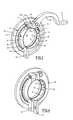
- FIG. 3is a left-side perspective view of an apical ring of the present invention in an open position.
- FIG. 4is a left-side perspective view of the apical ring of FIG. 3 in a closed position.
- FIG. 5is a front view of the apical ring of FIG. 3 with the clamp lever removed.
- FIG. 6is a right-side perspective view of the apical ring of FIG. 5 .
- FIG. 7is a top view of the apical ring of FIG. 5 .
- FIGS. 8 and 9are right-side perspective views of the apical ring of FIG. 3 is the open and closed positions, respectively.
- FIG. 10is a front view of the apical ring in the open position.
- FIG. 11is a front view showing the operation of the lever and the cam surface in greater detail.
- FIG. 12is an exploded, perspective view showing an attachment of the lever.
- FIG. 13is an exploded, perspective view showing the sealing disk with the apical ring.
- FIG. 14is a front view showing an alternative embodiment with a pair of complementary levers.
- FIG. 15is a front view showing an alternative embodiment with a screw adjustment.
- FIG. 16is a cross section showing the apical ring being used to clamp a plug for sealing the site when the pump is no longer needed.
- a patient 10is shown in fragmentary front elevational view.
- Surgically implanted into the patient's abdominal cavity 11is the pumping portion 12 of a ventricular assist device 13 .
- An inflow conduit 14conveys blood from the patient's left ventricle into the pumping portion 12
- an outflow conduit 15conveys blood from the pumping portion 12 to the patient's ascending thoracic aorta.
- a power cable 16extends from the pumping portion 12 outwardly of the patient's body via an incision to a compact controller 17 .
- a power source, such as battery packs 18is worn on a belt about the patient's waist and connected with controller 17 .
- Each of the conduits 14 and 15may include a tubular metallic housing proximate the pumping portion 12 .
- the conduitsare generally attached to the natural tissue by sutures through the use of a sewing ring or cuff so that blood flow communication is established and maintained.
- the distal end of the inflow conduit 14is inserted through the ventricle wall and into the heart in order to establish blood flow from the heart to the pumping portion 12 .
- Inflow conduit 14may be more preferably comprised of a rigid tube extending axially from the pump housing as shown in FIG. 2 . This allows for a shorter inflow conduit and for a more compact placement.
- left ventricle 21is accessed via apical ring or cuff 22 sutured to the apex of the heart and surrounding a section of heart tissue that is cored to provide a passage for conduit 14 .
- the outer surface of conduit 14preferably has a sintered coating in order to promote a stable blood surface and to facilitate sealing/coagulation between the outer diameter of conduit 14 and the ventricular wall.
- Apical ring 22clamps onto the same sintered surface. Due to variations in the manufacturing process using sintering, the resulting tolerance range of the outer diameter creates a challenge for providing consistent clamping without requiring adjustments to be made by a surgeon during attachment.
- FIGS. 3-11A first embodiment of an apical ring for overcoming the foregoing problems is shown in FIGS. 3-11 .
- an apical ring 24(preferably formed from a machined titanium alloy or other rigid material such as a biocompatible thermoplastic resin) may be associated with a sealing disk 25 that is sutured to and seals against the outer surface of the left ventricle.
- Ring 24includes an annular disk 26 that is disposed against sealing disk 25 .
- Ring 24further includes a collar 27 aligned with a central aperture 23 of disk 26 .
- Collar 27has a substantially cylindrical shape interrupted by a gap 32 between a first end 30 and a second end 31 .
- First and second ends 30 and 31may preferably be formed as enlarged blocks as shown.
- Collar 27has a fixed section 34 anchored to disk 26 and a cantilever section 33 extending from fixed section 34 but separated from disk 26 by a gap 35 .
- cantilever section 33provides an adjustable inside diameter in collar 27 .
- the initially manufactured placement of cantilever section 33provides an inside diameter sufficiently large to allow easy insertion of the inflow conduit.
- Cantilever section 33is subsequently clamped to a lesser inside diameter in order to secure the inflow conduit.
- Sealing disk 25has an inner edge 36 that is coaxial with central aperture 23 of annular disk 26 and collar 27 and has an inside diameter selected to provide a good seal around the inflow conduit.
- Sealing disk 25may preferably be comprised of a molded silicone body with a Dacron covering, for example.
- a first side of sealing disk 25bears against annular disk 26 and a second side bears against the heart.
- Annular disk 26includes a suturing flange 28 having a plurality of suturing holes 29 spaced around suturing flange 28 that may be formed within a trough in order to protect the sutures. Suturing holes 29 also pass through second end 31 .
- a tighteneris provided for selectively driving first end 30 toward second end 31 to close gap 32 for retaining the conduit within collar 27 once it is placed in its final location.
- the tightenermay be comprised of a C-clamp mechanism as shown in FIGS. 3-11 .
- Cantilever section 33includes relief slots 40 , 41 , and 42 penetrating first and second edges 43 and 44 of cantilever section 33 .
- Relief slots 40 - 42are expandable for extending the circumferential length of cantilever section 33 in response to interaction between the inflow conduit and the clamp when gap 32 is closed (e.g., in the manner of stretching of its length). More particularly, relief slots 40 - 42 act as a spring that is extendable around the inflow conduit when the conduit has some extra outer diameter to be accommodated.
- One or more relief slotscan be used, and preferably at least one relief slot is provided in each circumferential edge 43 and 44 . Each individual relief slot is not coaxial with any other relief slot (i.e., they are all offset as shown in FIG. 3 ).
- the C-clamp of FIGS. 3-11is comprised of a pivot pin 45 and a lever arm 46 .
- Pivot pin 45is disposed at a substantially fixed location with respect to annular disk 26 and is adjacent first end 30 .
- pivot pin 45may be attached to second end 31 by a screw 47 that passes through first end 30 and is threaded through pivot pin 45 .
- Lever 46has apertures 48 for receiving the ends of pivot pin 45 , whereby lever 46 rotates on pivot pin 45 between an open position as shown in FIG. 3 and a closed position as shown in FIG. 4 .
- Lever 46has a cam surface 50 that is slidable against first end 30 .
- Cam surface 50has a variable profile extending to a gradually larger radius away from pivot pin 45 in order to progressively drive first end 31 toward second end 30 as lever 46 rotates from the open position to the closed position.
- lever 46has a push tab 51 at its end to allow a surgeon to easily press on the clamp to move it to the closed position.
- Annular disk 26further includes a thumb tab 52 at a position diametrically opposite from first end 30 so that the surgeon can move the clamp to the closed position by pinching between tabs 51 and 52 .
- FIG. 4shows lever 46 moved to its closed position with tabs 51 and 52 brought face-to-face.
- the outer diameter of the inflow conduitis at the upper end of its tolerance range, reaching the closed position is achievable without requiring a screw adjustment.
- Closing effortremains small because relief slots 40 - 42 can spread slightly apart to provide the necessary increase of the circumferential length of cantilever section 33 .
- the overall profile (i.e., size) of ring 24 in its closed positionis relatively small and unobtrusive, thereby providing a compact and efficient system.
- first end 30may preferably include cam follower surface 55 alongside a groove 56 that receives pivot pin 45 .
- first end 30 , cam follower surface 55 , and groove 56are movable toward second end 31 to close gap 32 by virtue of slit 35 between cantilever section 33 and annular disk 26 .
- Protrusions 58FIG. 6
- Protrusions 58FIG. 6
- lever 46is limited to moving in a plane that is parallel with annular disk 26 .
- cam surface 50 on lever 46provides a minimum thickness section 60 and an increasing thickness section 61 .
- Section 60occupies the space between pivot pin 45 and first end 30 while in the open position as shown in FIG. 10 .
- a substantially flat section 62 of cam surface 50corresponds to the closed position of lever 46 .
- cam section 61Moving between the open and closed positions, cam section 61 progressively drives end 30 toward end 31 .
- the closed position shown in solid linesresults with lever 46 in the closed position in which end 30 is forced toward end 31 so that gap 32 is reduced or eliminated.
- FIG. 13shows a sewing pattern 57 on sealing disk 25 during attachment by suturing to the heart.
- FIG. 14An alternate embodiment shown in FIG. 14 employs a pair of opposed tightening clamps 65 and 67 disposed against collar ends 66 and 68 . Ends 66 and 68 are preferably each suspended by corresponding cantilever sections of the collar. Levers 65 and 67 may be attached to pivot pins 70 and 71 that are formed as fixed posts on annular disk 72 , for example. Alternatively, pivot pins 70 and 71 may be interconnected by a rod or shaft passing through corresponding holes in ends 66 and 68 .
- collar ends 75 and 76may be tightened using a threaded screw 77 .
- End 75is suspended on a cantilever section.
- Relief slots in the collarmay be useful with this screw-type tightener to help ensure that a full tolerance range of conduit outer diameters can be easily accommodated.
- Other hose-clamp type tightenerscan also be employed having relief slots.
- the present inventionfacilitates the releasing of the clamp in order to enable the adjustment of the position of the inflow conduit and pump as well as subsequent removal of the pump and/or inflow conduit for replacement with a different pump or inflow conduit.
- a plug 80 shown in FIG. 16can be clamped into ring 81 so that it passes through myocardium 82 and sealing disk 83 .
Landscapes
- Health & Medical Sciences (AREA)
- Heart & Thoracic Surgery (AREA)
- Engineering & Computer Science (AREA)
- Cardiology (AREA)
- Biomedical Technology (AREA)
- Anesthesiology (AREA)
- Hematology (AREA)
- Life Sciences & Earth Sciences (AREA)
- Animal Behavior & Ethology (AREA)
- General Health & Medical Sciences (AREA)
- Public Health (AREA)
- Veterinary Medicine (AREA)
- Vascular Medicine (AREA)
- Mechanical Engineering (AREA)
- External Artificial Organs (AREA)
Abstract
Description
Claims (15)
Priority Applications (4)
| Application Number | Priority Date | Filing Date | Title |
|---|---|---|---|
| US13/343,918US8579790B2 (en) | 2012-01-05 | 2012-01-05 | Apical ring for ventricular assist device |
| PCT/US2012/068921WO2013103480A1 (en) | 2012-01-05 | 2012-12-11 | Apical ring for ventricular assist device |
| US14/048,138US8840538B2 (en) | 2012-01-05 | 2013-10-08 | Apical ring for ventricular assist device |
| US14/484,498US20150005571A1 (en) | 2012-01-05 | 2014-09-12 | Apical ring for ventricular assist device |
Applications Claiming Priority (1)
| Application Number | Priority Date | Filing Date | Title |
|---|---|---|---|
| US13/343,918US8579790B2 (en) | 2012-01-05 | 2012-01-05 | Apical ring for ventricular assist device |
Related Child Applications (1)
| Application Number | Title | Priority Date | Filing Date |
|---|---|---|---|
| US14/048,138ContinuationUS8840538B2 (en) | 2012-01-05 | 2013-10-08 | Apical ring for ventricular assist device |
Publications (2)
| Publication Number | Publication Date |
|---|---|
| US20130178694A1 US20130178694A1 (en) | 2013-07-11 |
| US8579790B2true US8579790B2 (en) | 2013-11-12 |
Family
ID=47553386
Family Applications (3)
| Application Number | Title | Priority Date | Filing Date |
|---|---|---|---|
| US13/343,918Active2032-02-04US8579790B2 (en) | 2012-01-05 | 2012-01-05 | Apical ring for ventricular assist device |
| US14/048,138ActiveUS8840538B2 (en) | 2012-01-05 | 2013-10-08 | Apical ring for ventricular assist device |
| US14/484,498AbandonedUS20150005571A1 (en) | 2012-01-05 | 2014-09-12 | Apical ring for ventricular assist device |
Family Applications After (2)
| Application Number | Title | Priority Date | Filing Date |
|---|---|---|---|
| US14/048,138ActiveUS8840538B2 (en) | 2012-01-05 | 2013-10-08 | Apical ring for ventricular assist device |
| US14/484,498AbandonedUS20150005571A1 (en) | 2012-01-05 | 2014-09-12 | Apical ring for ventricular assist device |
Country Status (2)
| Country | Link |
|---|---|
| US (3) | US8579790B2 (en) |
| WO (1) | WO2013103480A1 (en) |
Cited By (15)
| Publication number | Priority date | Publication date | Assignee | Title |
|---|---|---|---|---|
| US8840538B2 (en) | 2012-01-05 | 2014-09-23 | Thoratec Corporation | Apical ring for ventricular assist device |
| US20150112120A1 (en)* | 2013-10-22 | 2015-04-23 | Heartware, Inc. | Anchored mounting ring |
| US9138228B2 (en) | 2004-08-11 | 2015-09-22 | Emory University | Vascular conduit device and system for implanting |
| US9144637B2 (en) | 2011-03-02 | 2015-09-29 | Thoratec Corporation | Ventricular cuff |
| US9199019B2 (en) | 2012-08-31 | 2015-12-01 | Thoratec Corporation | Ventricular cuff |
| US9308015B2 (en) | 2007-04-24 | 2016-04-12 | Emory University | Conduit device and system for implanting a conduit device in a tissue wall |
| US9320875B2 (en) | 2011-02-01 | 2016-04-26 | Emory University | Systems for implanting and using a conduit within a tissue wall |
| US9532773B2 (en) | 2011-01-28 | 2017-01-03 | Apica Cardiovascular Limited | Systems for sealing a tissue wall puncture |
| US9981076B2 (en) | 2012-03-02 | 2018-05-29 | Tc1 Llc | Ventricular cuff |
| US10028741B2 (en) | 2013-01-25 | 2018-07-24 | Apica Cardiovascular Limited | Systems and methods for percutaneous access, stabilization and closure of organs |
| US10485909B2 (en) | 2014-10-31 | 2019-11-26 | Thoratec Corporation | Apical connectors and instruments for use in a heart wall |
| US10518012B2 (en) | 2013-03-15 | 2019-12-31 | Apk Advanced Medical Technologies, Inc. | Devices, systems, and methods for implanting and using a connector in a tissue wall |
| US10894116B2 (en) | 2016-08-22 | 2021-01-19 | Tc1 Llc | Heart pump cuff |
| US11235137B2 (en) | 2017-02-24 | 2022-02-01 | Tc1 Llc | Minimally invasive methods and devices for ventricular assist device implantation |
| US11331466B2 (en) | 2019-02-28 | 2022-05-17 | Tc1 Llc | Inflow cannula including expandable sleeve and methods of implanting same |
Families Citing this family (52)
| Publication number | Priority date | Publication date | Assignee | Title |
|---|---|---|---|---|
| JP5171953B2 (en) | 2008-06-23 | 2013-03-27 | テルモ株式会社 | Blood pump device |
| WO2010042011A1 (en)* | 2008-10-10 | 2010-04-15 | Milux Holding Sa | Heart help device, system, and method |
| EP2372160B1 (en) | 2008-12-08 | 2014-07-30 | Thoratec Corporation | Centrifugal pump device |
| JP5378010B2 (en) | 2009-03-05 | 2013-12-25 | ソラテック コーポレーション | Centrifugal pump device |
| CN102341600B (en) | 2009-03-06 | 2014-12-10 | 胸腔科技有限公司 | Centrifugal pump device |
| US8821365B2 (en) | 2009-07-29 | 2014-09-02 | Thoratec Corporation | Rotation drive device and centrifugal pump apparatus using the same |
| JP5443197B2 (en) | 2010-02-16 | 2014-03-19 | ソラテック コーポレーション | Centrifugal pump device |
| JP5572832B2 (en) | 2010-03-26 | 2014-08-20 | ソーラテック コーポレイション | Centrifugal blood pump device |
| JP5681403B2 (en) | 2010-07-12 | 2015-03-11 | ソーラテック コーポレイション | Centrifugal pump device |
| JP5577506B2 (en) | 2010-09-14 | 2014-08-27 | ソーラテック コーポレイション | Centrifugal pump device |
| EP2693609B1 (en) | 2011-03-28 | 2017-05-03 | Thoratec Corporation | Rotation and drive device and centrifugal pump device using same |
| JP6083929B2 (en) | 2012-01-18 | 2017-02-22 | ソーラテック コーポレイション | Centrifugal pump device |
| US9371826B2 (en) | 2013-01-24 | 2016-06-21 | Thoratec Corporation | Impeller position compensation using field oriented control |
| US9556873B2 (en) | 2013-02-27 | 2017-01-31 | Tc1 Llc | Startup sequence for centrifugal pump with levitated impeller |
| US10052420B2 (en) | 2013-04-30 | 2018-08-21 | Tc1 Llc | Heart beat identification and pump speed synchronization |
| US9713663B2 (en) | 2013-04-30 | 2017-07-25 | Tc1 Llc | Cardiac pump with speed adapted for ventricle unloading |
| WO2015191954A1 (en)* | 2014-06-12 | 2015-12-17 | Endoluxe Inc. | Encasement platform for smartdevice for attachment to endoscope |
| CN106794294B (en)* | 2014-06-17 | 2019-03-26 | 心脏器械股份有限公司 | Connector ring fixture and related method of use |
| US9623161B2 (en) | 2014-08-26 | 2017-04-18 | Tc1 Llc | Blood pump and method of suction detection |
| US20160058930A1 (en)* | 2014-08-26 | 2016-03-03 | Thoratec Corporation | Blood pump and method of suction detection |
| EP3256183B1 (en) | 2015-02-11 | 2025-08-13 | Tc1 Llc | Heart beat identification and pump speed synchronization |
| US10371152B2 (en) | 2015-02-12 | 2019-08-06 | Tc1 Llc | Alternating pump gaps |
| EP3256185B1 (en) | 2015-02-12 | 2019-10-30 | Tc1 Llc | System and method for controlling the position of a levitated rotor |
| EP3256184B1 (en) | 2015-02-13 | 2020-04-08 | Tc1 Llc | Impeller suspension mechanism for heart pump |
| US10117983B2 (en) | 2015-11-16 | 2018-11-06 | Tc1 Llc | Pressure/flow characteristic modification of a centrifugal pump in a ventricular assist device |
| WO2017161317A1 (en)* | 2016-03-18 | 2017-09-21 | Everheart Systems Inc. | Cardiac connection for ventricular assist device |
| US9968720B2 (en) | 2016-04-11 | 2018-05-15 | CorWave SA | Implantable pump system having an undulating membrane |
| US10166319B2 (en) | 2016-04-11 | 2019-01-01 | CorWave SA | Implantable pump system having a coaxial ventricular cannula |
| WO2017218817A1 (en)* | 2016-06-15 | 2017-12-21 | Children's National Medical Center | Expanding-collapsing sewing ring to facilitate ventricular assist device implantation and explantation |
| EP3600479B1 (en) | 2017-03-31 | 2024-11-06 | CorWave SA | Implantable pump system having a rectangular membrane |
| CA3066361A1 (en) | 2017-06-07 | 2018-12-13 | Shifamed Holdings, Llc | Intravascular fluid movement devices, systems, and methods of use |
| CN107961407A (en)* | 2017-10-31 | 2018-04-27 | 深圳核心医疗器械有限公司 | The ventricle connection component and its assemble method of a kind of implanted artificial blood pump |
| FR3073578B1 (en) | 2017-11-10 | 2019-12-13 | Corwave | FLUID CIRCULATOR WITH RINGING MEMBRANE |
| WO2019094963A1 (en) | 2017-11-13 | 2019-05-16 | Shifamed Holdings, Llc | Intravascular fluid movement devices, systems, and methods of use |
| US10188779B1 (en) | 2017-11-29 | 2019-01-29 | CorWave SA | Implantable pump system having an undulating membrane with improved hydraulic performance |
| CN112004563B (en) | 2018-02-01 | 2024-08-06 | 施菲姆德控股有限责任公司 | Intravascular blood pump and methods of use and manufacture |
| US12161857B2 (en) | 2018-07-31 | 2024-12-10 | Shifamed Holdings, Llc | Intravascular blood pumps and methods of use |
| WO2020073047A1 (en) | 2018-10-05 | 2020-04-09 | Shifamed Holdings, Llc | Intravascular blood pumps and methods of use |
| WO2020115607A2 (en)* | 2018-12-05 | 2020-06-11 | CorWave SA | Apparatus and methods for coupling a blood pump to the heart |
| WO2020188453A1 (en) | 2019-03-15 | 2020-09-24 | CorWave SA | Systems and methods for controlling an implantable blood pump |
| WO2021011473A1 (en) | 2019-07-12 | 2021-01-21 | Shifamed Holdings, Llc | Intravascular blood pumps and methods of manufacture and use |
| US11654275B2 (en) | 2019-07-22 | 2023-05-23 | Shifamed Holdings, Llc | Intravascular blood pumps with struts and methods of use and manufacture |
| EP4501393A3 (en) | 2019-09-25 | 2025-04-09 | Shifamed Holdings, LLC | Catheter blood pumps and collapsible pump housings |
| WO2021062265A1 (en) | 2019-09-25 | 2021-04-01 | Shifamed Holdings, Llc | Intravascular blood pump systems and methods of use and control thereof |
| US12121713B2 (en) | 2019-09-25 | 2024-10-22 | Shifamed Holdings, Llc | Catheter blood pumps and collapsible blood conduits |
| EP4072650A4 (en) | 2019-12-11 | 2024-01-10 | Shifamed Holdings, LLC | Descending aorta and vena cava blood pumps |
| US11191946B2 (en) | 2020-03-06 | 2021-12-07 | CorWave SA | Implantable blood pumps comprising a linear bearing |
| CN113908428B (en)* | 2021-09-06 | 2022-07-15 | 深圳核心医疗科技有限公司 | Ventricular connection assembly and ventricular assist system |
| EP4514442A1 (en) | 2022-04-26 | 2025-03-05 | CorWave SA | Blood pumps having an encapsulated actuator |
| WO2024105583A1 (en)* | 2022-11-15 | 2024-05-23 | CorWave SA | Implantable heart pump system including an improved apical connector and/or graft connector |
| US12257427B2 (en) | 2022-11-15 | 2025-03-25 | CorWave SA | Implantable heart pump systems including an improved apical connector and/or graft connector |
| CN117815535B (en)* | 2023-12-30 | 2025-08-26 | 深圳核心医疗科技股份有限公司 | Ventricular connection mechanism and ventricular assist system |
Citations (26)
| Publication number | Priority date | Publication date | Assignee | Title |
|---|---|---|---|---|
| US1093868A (en)* | 1912-03-11 | 1914-04-21 | Henry W Jacobs | Means for forming couplings or joints. |
| US4790843A (en) | 1986-06-16 | 1988-12-13 | Baxter Travenol Laboratories, Inc. | Prosthetic heart valve assembly |
| US5354331A (en) | 1992-07-15 | 1994-10-11 | Schachar Ronald A | Treatment of presbyopia and other eye disorders |
| US5504978A (en) | 1994-07-15 | 1996-04-09 | Meyer, Iii; Harold A. | Locking clamp assembly |
| US5824069A (en) | 1996-09-13 | 1998-10-20 | Medtronic, Inc. | Prosthetic heart valve with suturing member having non-uniform radial width |
| US6143025A (en) | 1996-07-29 | 2000-11-07 | Edwards Lifesciences Corporation | Suture rings for rotatable artificial heart valves |
| US6146325A (en) | 1999-06-03 | 2000-11-14 | Arrow International, Inc. | Ventricular assist device |
| US6319231B1 (en) | 1999-02-12 | 2001-11-20 | Abiomed, Inc. | Medical connector |
| US20020058994A1 (en) | 2000-11-16 | 2002-05-16 | Hill J Donald | Automatic suture fixation apparatus and method for minimally invasive cardiac surgery |
| US20020095210A1 (en) | 2001-01-16 | 2002-07-18 | Finnegan Michael T. | Heart pump graft connector and system |
| US6458163B1 (en) | 2000-07-11 | 2002-10-01 | Prosthetic Design, Inc. | Coupling-socket adapter assembly for a prosthetic limb |
| US20030023302A1 (en) | 2001-07-26 | 2003-01-30 | Riyad Moe | Sewing cuff assembly for heart valves |
| US20040007515A1 (en) | 2002-07-15 | 2004-01-15 | Geyer Frederick J. | Filter assembly having improved sealing features |
| US20040015232A1 (en) | 2002-07-16 | 2004-01-22 | Medtronic, Inc. | Suturing rings for implantable heart valve prosthesis |
| US20040024285A1 (en) | 2002-06-21 | 2004-02-05 | Helmut Muckter | Blood pump with impeller |
| US20040030381A1 (en) | 2002-07-16 | 2004-02-12 | Shu Mark C.S. | Heart valve prosthesis |
| US6732501B2 (en) | 2002-06-26 | 2004-05-11 | Heartware, Inc. | Ventricular connector |
| US20040210305A1 (en) | 2002-07-16 | 2004-10-21 | Medtronic, Inc. | Suture locking assembly and method of use |
| US6942672B2 (en) | 2001-10-23 | 2005-09-13 | Vascor, Inc. | Method and apparatus for attaching a conduit to the heart or a blood vessel |
| US7048681B2 (en) | 2003-03-28 | 2006-05-23 | Terumo Corporation | Method and apparatus for adjusting a length of the inflow conduit on a ventricular assist device |
| US20070134993A1 (en) | 2005-12-08 | 2007-06-14 | Daniel Tamez | Implant connector |
| US20070213690A1 (en) | 2006-03-08 | 2007-09-13 | Nickolas Phillips | Blood conduit connector |
| US20090171136A1 (en) | 2007-12-27 | 2009-07-02 | Shambaugh Jr Charles R | VAD connector plug |
| US20110118829A1 (en) | 2009-11-15 | 2011-05-19 | Thoratec Corporation | Attachment device and method |
| US20110118833A1 (en) | 2009-11-15 | 2011-05-19 | Thoratec Corporation | Attachment device and method |
| US20110118766A1 (en) | 2009-11-15 | 2011-05-19 | Thoratec Corporation | Attachment System, Device and Method |
Family Cites Families (15)
| Publication number | Priority date | Publication date | Assignee | Title |
|---|---|---|---|---|
| US6065853A (en)* | 1998-05-19 | 2000-05-23 | Crevier; Kirk D. | Driveway, walkway and landscape lighting |
| US6726648B2 (en) | 2000-08-14 | 2004-04-27 | The University Of Miami | Valved apical conduit with trocar for beating-heart ventricular assist device placement |
| US8241309B2 (en)* | 2001-06-29 | 2012-08-14 | World Heart Corporation | Cannulation apparatus and method |
| US8292908B2 (en) | 2001-06-29 | 2012-10-23 | World Heart Corporation | Endoscopic cannulation apparatus and method |
| WO2005094525A2 (en) | 2004-03-23 | 2005-10-13 | Correx, Inc. | Apparatus and method for connecting a conduit to a hollow organ |
| US9138228B2 (en) | 2004-08-11 | 2015-09-22 | Emory University | Vascular conduit device and system for implanting |
| CN101968144B (en)* | 2005-03-04 | 2012-07-04 | 诺玛美国控股有限责任公司 | T-bolt clamp quick attach latch |
| US8343028B2 (en) | 2005-10-19 | 2013-01-01 | Thoratec Corporation | Ventricular pump coupling |
| US7717844B2 (en) | 2006-07-06 | 2010-05-18 | Apaxis Medical, Inc. | Method and apparatus for stabilization and positioning during surgery |
| US7846123B2 (en) | 2007-04-24 | 2010-12-07 | Emory University | Conduit device and system for implanting a conduit device in a tissue wall |
| US8915958B2 (en) | 2007-06-08 | 2014-12-23 | St. Jude Medical, Inc. | Devices for transcatheter prosthetic heart valve implantation and access closure |
| WO2009100198A2 (en) | 2008-02-08 | 2009-08-13 | Mayo Foundation For Medical Education And Research | Transapical heart port |
| WO2010015836A1 (en)* | 2008-08-08 | 2010-02-11 | Calon Cardio Technology Ltd | Heart assist apparatus |
| JP5744893B2 (en) | 2009-11-09 | 2015-07-08 | アントラージュ メディカル テクノロジーズ,インコーポレイテッドEntourage Medical Technologies,Inc. | Systems that provide access and closure to the organization |
| US8579790B2 (en) | 2012-01-05 | 2013-11-12 | Thoratec Corporation | Apical ring for ventricular assist device |
- 2012
- 2012-01-05USUS13/343,918patent/US8579790B2/enactiveActive
- 2012-12-11WOPCT/US2012/068921patent/WO2013103480A1/enactiveApplication Filing
- 2013
- 2013-10-08USUS14/048,138patent/US8840538B2/enactiveActive
- 2014
- 2014-09-12USUS14/484,498patent/US20150005571A1/ennot_activeAbandoned
Patent Citations (27)
| Publication number | Priority date | Publication date | Assignee | Title |
|---|---|---|---|---|
| US1093868A (en)* | 1912-03-11 | 1914-04-21 | Henry W Jacobs | Means for forming couplings or joints. |
| US4790843A (en) | 1986-06-16 | 1988-12-13 | Baxter Travenol Laboratories, Inc. | Prosthetic heart valve assembly |
| US5354331A (en) | 1992-07-15 | 1994-10-11 | Schachar Ronald A | Treatment of presbyopia and other eye disorders |
| US5504978A (en) | 1994-07-15 | 1996-04-09 | Meyer, Iii; Harold A. | Locking clamp assembly |
| US6143025A (en) | 1996-07-29 | 2000-11-07 | Edwards Lifesciences Corporation | Suture rings for rotatable artificial heart valves |
| US5824069A (en) | 1996-09-13 | 1998-10-20 | Medtronic, Inc. | Prosthetic heart valve with suturing member having non-uniform radial width |
| US6319231B1 (en) | 1999-02-12 | 2001-11-20 | Abiomed, Inc. | Medical connector |
| US6146325A (en) | 1999-06-03 | 2000-11-14 | Arrow International, Inc. | Ventricular assist device |
| US6458163B1 (en) | 2000-07-11 | 2002-10-01 | Prosthetic Design, Inc. | Coupling-socket adapter assembly for a prosthetic limb |
| US20020058994A1 (en) | 2000-11-16 | 2002-05-16 | Hill J Donald | Automatic suture fixation apparatus and method for minimally invasive cardiac surgery |
| US20020095210A1 (en) | 2001-01-16 | 2002-07-18 | Finnegan Michael T. | Heart pump graft connector and system |
| US20030023302A1 (en) | 2001-07-26 | 2003-01-30 | Riyad Moe | Sewing cuff assembly for heart valves |
| US6942672B2 (en) | 2001-10-23 | 2005-09-13 | Vascor, Inc. | Method and apparatus for attaching a conduit to the heart or a blood vessel |
| US20040024285A1 (en) | 2002-06-21 | 2004-02-05 | Helmut Muckter | Blood pump with impeller |
| US6732501B2 (en) | 2002-06-26 | 2004-05-11 | Heartware, Inc. | Ventricular connector |
| US20040171905A1 (en) | 2002-06-26 | 2004-09-02 | HeartWare, Inc, (a Delaware Corporation) | Ventricular connector |
| US20040007515A1 (en) | 2002-07-15 | 2004-01-15 | Geyer Frederick J. | Filter assembly having improved sealing features |
| US20040030381A1 (en) | 2002-07-16 | 2004-02-12 | Shu Mark C.S. | Heart valve prosthesis |
| US20040210305A1 (en) | 2002-07-16 | 2004-10-21 | Medtronic, Inc. | Suture locking assembly and method of use |
| US20040015232A1 (en) | 2002-07-16 | 2004-01-22 | Medtronic, Inc. | Suturing rings for implantable heart valve prosthesis |
| US7048681B2 (en) | 2003-03-28 | 2006-05-23 | Terumo Corporation | Method and apparatus for adjusting a length of the inflow conduit on a ventricular assist device |
| US20070134993A1 (en) | 2005-12-08 | 2007-06-14 | Daniel Tamez | Implant connector |
| US20070213690A1 (en) | 2006-03-08 | 2007-09-13 | Nickolas Phillips | Blood conduit connector |
| US20090171136A1 (en) | 2007-12-27 | 2009-07-02 | Shambaugh Jr Charles R | VAD connector plug |
| US20110118829A1 (en) | 2009-11-15 | 2011-05-19 | Thoratec Corporation | Attachment device and method |
| US20110118833A1 (en) | 2009-11-15 | 2011-05-19 | Thoratec Corporation | Attachment device and method |
| US20110118766A1 (en) | 2009-11-15 | 2011-05-19 | Thoratec Corporation | Attachment System, Device and Method |
Cited By (28)
| Publication number | Priority date | Publication date | Assignee | Title |
|---|---|---|---|---|
| US9138228B2 (en) | 2004-08-11 | 2015-09-22 | Emory University | Vascular conduit device and system for implanting |
| US9308015B2 (en) | 2007-04-24 | 2016-04-12 | Emory University | Conduit device and system for implanting a conduit device in a tissue wall |
| US11027103B2 (en) | 2007-04-24 | 2021-06-08 | Emory University | Conduit device and system for implanting a conduit device in a tissue wall |
| US9950146B2 (en) | 2007-04-24 | 2018-04-24 | Emory Univeristy | Conduit device and system for implanting a conduit device in a tissue wall |
| US9532773B2 (en) | 2011-01-28 | 2017-01-03 | Apica Cardiovascular Limited | Systems for sealing a tissue wall puncture |
| US10357232B2 (en) | 2011-01-28 | 2019-07-23 | Apica Cardiovascular Limited | Systems for sealing a tissue wall puncture |
| US9320875B2 (en) | 2011-02-01 | 2016-04-26 | Emory University | Systems for implanting and using a conduit within a tissue wall |
| US10499949B2 (en) | 2011-02-01 | 2019-12-10 | Emory University | Systems for implanting and using a conduit within a tissue wall |
| US9750858B2 (en) | 2011-03-02 | 2017-09-05 | Tc1 Llc | Ventricular cuff |
| US9144637B2 (en) | 2011-03-02 | 2015-09-29 | Thoratec Corporation | Ventricular cuff |
| US11185683B2 (en) | 2011-03-02 | 2021-11-30 | Tc1 Llc | Ventricular cuff |
| US10525177B2 (en) | 2011-03-02 | 2020-01-07 | Tc1 Llc | Ventricular cuff |
| US10111993B2 (en) | 2011-03-02 | 2018-10-30 | Tc1 Llc | Ventricular cuff |
| US8840538B2 (en) | 2012-01-05 | 2014-09-23 | Thoratec Corporation | Apical ring for ventricular assist device |
| US9981076B2 (en) | 2012-03-02 | 2018-05-29 | Tc1 Llc | Ventricular cuff |
| US11369785B2 (en) | 2012-03-02 | 2022-06-28 | Tc1 Llc | Ventricular cuff |
| US9981077B2 (en) | 2012-08-31 | 2018-05-29 | Tc1 Llc | Ventricular cuff |
| US9199019B2 (en) | 2012-08-31 | 2015-12-01 | Thoratec Corporation | Ventricular cuff |
| US11116542B2 (en) | 2013-01-25 | 2021-09-14 | Apica Cardiovascular Limited | Systems and methods for percutaneous access, stabilization and closure of organs |
| US10028741B2 (en) | 2013-01-25 | 2018-07-24 | Apica Cardiovascular Limited | Systems and methods for percutaneous access, stabilization and closure of organs |
| US10518012B2 (en) | 2013-03-15 | 2019-12-31 | Apk Advanced Medical Technologies, Inc. | Devices, systems, and methods for implanting and using a connector in a tissue wall |
| US20150112120A1 (en)* | 2013-10-22 | 2015-04-23 | Heartware, Inc. | Anchored mounting ring |
| US10279092B2 (en)* | 2013-10-22 | 2019-05-07 | Heartware, Inc. | Anchored mounting ring |
| US10485909B2 (en) | 2014-10-31 | 2019-11-26 | Thoratec Corporation | Apical connectors and instruments for use in a heart wall |
| US10894116B2 (en) | 2016-08-22 | 2021-01-19 | Tc1 Llc | Heart pump cuff |
| US11583671B2 (en) | 2016-08-22 | 2023-02-21 | Tc1 Llc | Heart pump cuff |
| US11235137B2 (en) | 2017-02-24 | 2022-02-01 | Tc1 Llc | Minimally invasive methods and devices for ventricular assist device implantation |
| US11331466B2 (en) | 2019-02-28 | 2022-05-17 | Tc1 Llc | Inflow cannula including expandable sleeve and methods of implanting same |
Also Published As
| Publication number | Publication date |
|---|---|
| US20150005571A1 (en) | 2015-01-01 |
| US20140155682A1 (en) | 2014-06-05 |
| WO2013103480A1 (en) | 2013-07-11 |
| US8840538B2 (en) | 2014-09-23 |
| US20130178694A1 (en) | 2013-07-11 |
Similar Documents
| Publication | Publication Date | Title |
|---|---|---|
| US8579790B2 (en) | Apical ring for ventricular assist device | |
| US8882744B2 (en) | Quick-connect outflow tube for ventricular assist device | |
| EP2519273B1 (en) | Blood pump system with mounting cuff | |
| US8152845B2 (en) | Blood pump system with mounting cuff | |
| US20190314612A1 (en) | Cannula ring and related systems and methods | |
| EP1789129B1 (en) | Heart pump connector | |
| US6942672B2 (en) | Method and apparatus for attaching a conduit to the heart or a blood vessel | |
| US7048681B2 (en) | Method and apparatus for adjusting a length of the inflow conduit on a ventricular assist device | |
| KR101415280B1 (en) | Implant connector | |
| EP2707053B1 (en) | Intravascular blood pump and method of implantation | |
| US7172550B2 (en) | Adjustable coupling mechanism for the conduit on a ventricular assist device | |
| WO2010080107A1 (en) | Cardiovascular valve and valve housing apparatuses and systems | |
| EP3389739B1 (en) | Hollow plug | |
| WO2018195301A1 (en) | Aortic connectors and methods of use | |
| AU2013231115B2 (en) | Blood pump system with mounting cuff |
Legal Events
| Date | Code | Title | Description |
|---|---|---|---|
| AS | Assignment | Owner name:TERUMO KABUSHIKI KAISHA, JAPAN Free format text:ASSIGNMENT OF ASSIGNORS INTEREST;ASSIGNORS:JEFFERY, BRIAN D.;DASARA, SUNIL K.;REEL/FRAME:027483/0774 Effective date:20120104 | |
| AS | Assignment | Owner name:THORATEC CORPORATION, CALIFORNIA Free format text:ASSIGNMENT OF ASSIGNORS INTEREST;ASSIGNOR:TERUMO KABUSHIKI KAISHA;REEL/FRAME:031016/0364 Effective date:20130630 | |
| STCF | Information on status: patent grant | Free format text:PATENTED CASE | |
| AS | Assignment | Owner name:THORATEC LLC, CALIFORNIA Free format text:CHANGE OF NAME;ASSIGNOR:THORATEC CORPORATION;REEL/FRAME:041428/0327 Effective date:20151112 Owner name:TC1 LLC, CALIFORNIA Free format text:ASSIGNMENT OF ASSIGNORS INTEREST;ASSIGNOR:THORATEC LLC;REEL/FRAME:041428/0685 Effective date:20161114 | |
| FPAY | Fee payment | Year of fee payment:4 | |
| MAFP | Maintenance fee payment | Free format text:PAYMENT OF MAINTENANCE FEE, 8TH YEAR, LARGE ENTITY (ORIGINAL EVENT CODE: M1552); ENTITY STATUS OF PATENT OWNER: LARGE ENTITY Year of fee payment:8 | |
| MAFP | Maintenance fee payment | Free format text:PAYMENT OF MAINTENANCE FEE, 12TH YEAR, LARGE ENTITY (ORIGINAL EVENT CODE: M1553); ENTITY STATUS OF PATENT OWNER: LARGE ENTITY Year of fee payment:12 |