US8579115B2 - Protective containers for medical devices and methods of use - Google Patents
Protective containers for medical devices and methods of useDownload PDFInfo
- Publication number
- US8579115B2 US8579115B2US12/869,614US86961410AUS8579115B2US 8579115 B2US8579115 B2US 8579115B2US 86961410 AUS86961410 AUS 86961410AUS 8579115 B2US8579115 B2US 8579115B2
- Authority
- US
- United States
- Prior art keywords
- needle
- base
- container
- catheter
- cap
- Prior art date
- Legal status (The legal status is an assumption and is not a legal conclusion. Google has not performed a legal analysis and makes no representation as to the accuracy of the status listed.)
- Active, expires
Links
Images


Classifications
- A—HUMAN NECESSITIES
- A61—MEDICAL OR VETERINARY SCIENCE; HYGIENE
- A61M—DEVICES FOR INTRODUCING MEDIA INTO, OR ONTO, THE BODY; DEVICES FOR TRANSDUCING BODY MEDIA OR FOR TAKING MEDIA FROM THE BODY; DEVICES FOR PRODUCING OR ENDING SLEEP OR STUPOR
- A61M5/00—Devices for bringing media into the body in a subcutaneous, intra-vascular or intramuscular way; Accessories therefor, e.g. filling or cleaning devices, arm-rests
- A61M5/002—Packages specially adapted therefor, e.g. for syringes or needles, kits for diabetics
- A—HUMAN NECESSITIES
- A61—MEDICAL OR VETERINARY SCIENCE; HYGIENE
- A61L—METHODS OR APPARATUS FOR STERILISING MATERIALS OR OBJECTS IN GENERAL; DISINFECTION, STERILISATION OR DEODORISATION OF AIR; CHEMICAL ASPECTS OF BANDAGES, DRESSINGS, ABSORBENT PADS OR SURGICAL ARTICLES; MATERIALS FOR BANDAGES, DRESSINGS, ABSORBENT PADS OR SURGICAL ARTICLES
- A61L2/00—Methods or apparatus for disinfecting or sterilising materials or objects other than foodstuffs or contact lenses; Accessories therefor
- A61L2/26—Accessories or devices or components used for biocidal treatment
- A—HUMAN NECESSITIES
- A61—MEDICAL OR VETERINARY SCIENCE; HYGIENE
- A61M—DEVICES FOR INTRODUCING MEDIA INTO, OR ONTO, THE BODY; DEVICES FOR TRANSDUCING BODY MEDIA OR FOR TAKING MEDIA FROM THE BODY; DEVICES FOR PRODUCING OR ENDING SLEEP OR STUPOR
- A61M5/00—Devices for bringing media into the body in a subcutaneous, intra-vascular or intramuscular way; Accessories therefor, e.g. filling or cleaning devices, arm-rests
- A61M5/001—Apparatus specially adapted for cleaning or sterilising syringes or needles
- A—HUMAN NECESSITIES
- A61—MEDICAL OR VETERINARY SCIENCE; HYGIENE
- A61L—METHODS OR APPARATUS FOR STERILISING MATERIALS OR OBJECTS IN GENERAL; DISINFECTION, STERILISATION OR DEODORISATION OF AIR; CHEMICAL ASPECTS OF BANDAGES, DRESSINGS, ABSORBENT PADS OR SURGICAL ARTICLES; MATERIALS FOR BANDAGES, DRESSINGS, ABSORBENT PADS OR SURGICAL ARTICLES
- A61L2202/00—Aspects relating to methods or apparatus for disinfecting or sterilising materials or objects
- A61L2202/10—Apparatus features
- A61L2202/18—Aseptic storing means
- A61L2202/182—Rigid packaging means
- A—HUMAN NECESSITIES
- A61—MEDICAL OR VETERINARY SCIENCE; HYGIENE
- A61L—METHODS OR APPARATUS FOR STERILISING MATERIALS OR OBJECTS IN GENERAL; DISINFECTION, STERILISATION OR DEODORISATION OF AIR; CHEMICAL ASPECTS OF BANDAGES, DRESSINGS, ABSORBENT PADS OR SURGICAL ARTICLES; MATERIALS FOR BANDAGES, DRESSINGS, ABSORBENT PADS OR SURGICAL ARTICLES
- A61L2202/00—Aspects relating to methods or apparatus for disinfecting or sterilising materials or objects
- A61L2202/20—Targets to be treated
- A61L2202/24—Medical instruments, e.g. endoscopes, catheters, sharps
Definitions
- This disclosurerelates generally to the field of containers and specifically to containers that hold and protect medical devices, such as needles and/or catheters, for transport and storage.
- Medical devicesoften require special care when stored and transported prior to use. In some situations, the devices can cause damage or injury if accidentally brought into contact with a person, such as when a medical needle inadvertently pierces someone's skin. In addition, medical devices are often fragile and can be damaged easily if not protected. Moreover, in many situations, medical devices must be exposed to a sterilization procedure during the manufacturing process and then must be maintained in a sterile environment until used. These factors present challenges to those who manufacture, transport, and use medical devices. These challenges can be especially difficult in fast-paced, urgent-care medical settings, such as in emergency facilities in hospitals, on the battlefield, and in civil first-responder situations.
- kitssuch as those used for administering intravenous fluid.
- Some kitscan include decompression hypodermic needles intended for use in the management of combat casualties who present signs and symptoms of tension pneumothorax.
- needles and catheterscome packaged in a flexible paper and plastic wrapper that does little to protect the contents inside from physical impacts and other stresses. In some circumstances, the devices may even poke through the paper packaging and thereby lose sterility or even cause personal injury.
- medical device containersthat protect medical devices from damage or contamination, and also protect persons who are storing, transporting, or using the devices from inadvertent injury.
- the containerscan be lightweight, extremely durable, and can be opened quickly.
- the medical device containersare also configured to permit sterilization of medical devices which are positioned therein, and the containers can maintain these devices in a sterile environment thereafter until used.
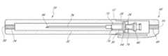
- FIG. 1is a schematic perspective view of an example of a container according to an embodiment in the present application.
- FIG. 2is a schematic exploded perspective view of the container of FIG. 1 .
- FIG. 3is a schematic side elevation view of a base of the container of FIG. 1 .
- FIG. 4is a cross-sectional schematic side elevation view of the base of FIG. 3 taken at line 4 - 4 .
- FIG. 5is a cross-sectional schematic side elevation view of the base of FIG. 4 taken at line 5 - 5 .
- FIG. 6is an enlarged schematic side elevation view of a cap of the container of FIG. 1 .
- FIG. 7is a cross-sectional schematic side elevation view of the cap of FIG. 6 taken at line 7 - 7 .
- FIG. 8is a schematic top perspective view of the protective case of FIG. 1 with a medical device disposed therein.
- FIG. 9is a close-up view of detail 9 of FIG. 8 .
- FIG. 10is a cross-sectional schematic side elevation view of the container of FIG. 8 taken along line 10 - 10 .
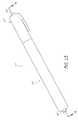
- FIG. 11is a schematic perspective view of a container according to another embodiment in the present application.
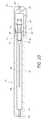
- FIG. 12is a cross-sectional schematic side elevation view of the container of FIG. 11 taken along line 12 - 12 .
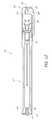
- FIG. 13is a schematic top perspective view of a container according to another embodiment in the present application.
- FIG. 14is a cross-sectional schematic side elevation view of the container of FIG. 11 taken along line 14 - 14 .
- protective containersfor sterilizing, storing and transporting needles and catheters are described herein. None of these examples should be understood to limit the inventions recited in the claims. None of the structures, steps, or other features disclosed herein are essential or indispensible; any can be omitted in some embodiments. Some of the protective containers disclosed herein can be particularly advantageous for use in rugged and abusive combat or military environments, and also can allow inexpensive and effective sterilization techniques.
- distalis used to describe the direction toward the bottom of the container 10 and the term “proximal” is used to describe the direction toward the top of the container 10 .
- distalis toward the end of the container 10 with the base 20 .
- proximalis toward the end of the container 10 with the cap 40 .
- a protective needle container having desirable features and advantageswill now be described with reference to the figures.
- the features of the present needle containercan provide advantages in many other applications as well.
- the containercan hold many other types of devices, such as medical devices with a catheter instead of, or in addition to, a needle.
- a needlecan be disposed within a sheath of a catheter and positioned in the container.
- the containercan be configured to be used with non-medical items.
- FIG. 1illustrates an embodiment of the container 10 that includes a base 20 and a cap 40 .
- the base 20is an elongate member with a longitudinal length sufficient to accommodate all or a portion of the length of a medical device to be stored therein, such as a needle.
- the cap 40can be detachably coupled to an end of the base 20 .
- the container 10is illustrated with the cap 40 detached from the base 20 .
- the base 20can have a mating portion 22 that is configured to couple with the cap 40 .
- the mating portion 22can have an outer diameter that is less than the outer diameter of the outer surface of the base 24 .
- the difference between the radius of the outer surface of the base 24 and the radius of the mating portion 22can be substantially equal to the thickness t of the cap 40 , such that the outer surface of the cap 44 is substantially flush with the outer surface of the base 24 when the cap 40 is coupled to the base 20 , as illustrated in FIG. 1 .
- a flush interface between the base 20 and cap 40can advantageously reduce the likelihood of the container 10 becoming inadvertently caught or snagged on other objects, which can result in unintentional separation of the base 20 and cap 40 . In some applications, this can be important because of the abusive conditions experienced by the container 10 and the myriad of equipment on which the container 10 can potentially become snagged.
- the base 20 and cap 40can be temporarily held together by a coupling 12 , such as adhesive tape, that is placed across the seam between the base 20 and cap 40 .
- the coupling 12can have perforations 14 or a weakened portion where the coupling 12 can separate to detach the cap 40 from the base 20 .
- the breakable coupling 12can advantageously allow rapid deployment of the medical device by simply twisting or pulling the cap 40 from the base 20 while diminishing the risk of accidental or unintended detachment.
- a broken coupling 12can evidence when the container 10 has been used or tampered with, thus indicating that the medical device inside may no longer be sterile.
- the coupling 12can be labeled or coded, such as to indicate the type of medical device contained inside.
- the coupling 12can indicate when the container 10 has been sterilized.
- the coupling 12can include a substance that changes color when it reacts with chemicals used in gas sterilization.
- the cap 40 and base 20can be attached using an attachment structure, such as surfaces that produce a friction fit, as described further below.
- the cap 40can have threads that can engage with complementary threads on the mating portion 22 .
- the mating portion 22can have a ridge extending around the circumference of the mating surface that fits into a depression extending around the inner surface 42 of the cap 40 .
- the mating portion 22can have tabs, hooks, ridges, etc. that can couple with complementary features on the cap 40 .
- the base 20can have any other attachment structure around the mating portion 22 that can interact with a complementary feature on the inner surface 42 of the cap 40 .
- the base 20may not have a mating portion 22 and the cap 40 can couple to other portions of the base 20 through any coupling features, such as for example hooks, tabs, magnets, etc.
- the cap 40can have a male portion and the base 20 can have a female portion such that the cap 40 can be inserted into the base 20 to couple the two components.
- the base 20can have a cavity with an inner surface that can couple with an external surface of the cap 40 .
- the base 20can be an elongate member with a longitudinal axis and a length sufficient to accommodate the length of a needle.
- the base 20can be formed in many different shapes and sizes.
- the total length of the base 20can be approximately 127 mm.
- the total length of the base 20can range from approximately 50 mm to approximately 254 mm.
- the base 20can be any appropriate length to accommodate an item to be contained at least partially therein.
- the base 20is a generally cylindrical member.
- the base 20can have a generally triangular, square, polygonal or ovular cross-sectional shape.
- the base 20can have any other cross-sectional shape, and the shape of the base 20 can change along its length.
- the outer diameter of the generally cylindrical base 20 in the illustrated embodimentis approximately 14 mm.
- the diameter of the base 20can range from approximately 8 mm to approximately 30 mm.
- the provided measurementsare for the transverse width, measured perpendicular to the longitudinal axis of the base 20 .
- the diameter or widthcan be any appropriate size to accommodate a certain category of items.
- the basecan have a width sufficient to accommodate more than one type of device, such as a plurality of needles of different sizes.
- the basecan be formed as a generally wide, flat structure with multiple cavities lined up along the width for accepting multiple needle sizes.
- the base 20can have a mating portion 22 at or near the proximal end, which can couple with the cap 40 .
- the mating portion 22has a generally cylindrical shape and a length configured to be inserted into a portion of the cap 40 .
- the mating portion 22can have a generally triangular, square, polygonal or ovular cross-sectional shape. In other embodiments, the mating portion 22 can have any other cross-sectional shape.
- the length of the mating portion 22can be approximately 13 mm. In some embodiments, the length of the mating portion 22 can range from approximately 3 mm to approximately 30 mm. In other embodiments, the mating portion 22 can be longer than approximately 30 mm.
- the mating portion 22can have an outer diameter, or transverse width, that is less than the outer diameter of the outer surface of the base 24 .
- the diameter or width of the mating portion 22can be approximately 12 mm.
- the diameter or width of the mating portion 22can range from approximately 7 mm to approximately 30 mm.
- the mating portion 22can have a diameter or width that increases in the distal direction to provide increasing compression forces as the base 20 and cap 40 are coupled together.
- the base 20can be made of a material that can withstand the abuses and impacts associated with the rigors experienced by equipment used by military or emergency personnel.
- the base 20can be made of a rigid material that substantially resists bending to protect the needle contained within.
- the materialcan also be generally crush resistant such that the contents are protected from impacts and compression forces that may ordinarily be encountered by persons who are storing, transporting, or using medical devices in urgent circumstances.
- the materialis impervious or substantially impervious to most or generally all gaseous, liquid or solid contaminants.
- the materialcan be malleable in a forming stage for ease of manufacturing, through processes such as molding, vacuum forming, machining, etc.
- suitable materialsinclude, but are not limited to, plastics, metals, fiberglass and composites.
- the base 20can be made of high density polyethylene plastic.
- FIGS. 4 and 5illustrate cross-sectional views of the base 20 .
- FIG. 4illustrates a cross-section taken at line 4 - 4 in FIG. 3 .
- FIG. 5illustrates a cross-section taken at line 5 - 5 in FIG. 4 .
- FIG. 10also illustrates, inter alia, a cross-sectional view of the base 20 , cap 40 , as well as a schematic of an example of a needle 60 and catheter 70 .
- the base 20can have a first containing region, such as a flange region 26 at or near the proximal end of the base 20 .
- the flange region 26can comprise a cavity with a shape substantially corresponding to the shape of at least a portion of a device to be container therein.
- the flange region 26can be adapted to receive a flange on a needle hub 62 and/or catheter hub 72 .
- the flange region 26can accept the flanges to securely retain the needle within the base 20 , as described in more detail herein.
- Extending distally from the distal end of the flange region 26can be a second containing region with the container 10 , such as a hub cavity 30 .
- the first and second containing regionscan have different cross-sectional diameters or widths to accommodate or engage with different portion of items to be container therein.
- the hub cavity 30can be configured to accommodate the needle hub 62 and/or catheter hub 72 .
- the length of the hub cavity 30can be approximately 20 mm.
- the hub cavity 30can have a clearance region between with the needle hub 62 and/or catheter hub 72 and the inner wall of the container 10 , such that the sides of the hubs do not contact the sides of the hub cavity 30 when the needle is properly coupled to the base 20 during storage or transportation.
- the hub cavity 30can be a generally cylindrical cavity having a diameter of approximately 5.5 mm. In some embodiments, the hub cavity 30 can have a diameter ranging from about 4 mm to about 30 mm.
- the hub cavity 30can have a non-circular shape, such as for example a rectangular, square, ovular or polygonal cross-section. In some embodiments, the hub cavity 30 can have any shape that is configured to accept the shape of the needle hub 62 and/or catheter hub 72 .
- the hub cavity 30can have a close fit or interference fit with a portion of the item contained therein, such as the needle hub 62 and/or catheter hub 72 , to provide generally rigid retention of at least a portion of the device while permitting another portion of the device (which may be more fragile) to be positioned more loosely within the container 10 .
- This configurationcan help prevent forces applied on the exterior of the container 10 from being transferred indirectly to the needle in a damaging way, causing the needle to be jostled excessively within the base 20 during transport of the container 10 .
- the hub cavity 30can have a generally frustoconical shape where the diameter of the hub cavity 30 decreases in the distal direction such that the needle hub 62 and/or catheter hub 72 can be gripped tighter as it advances distally into the hub cavity 30 .
- the hub cavitycan have walls that are tapered such that the distance between the walls decreases in the distal direction to provide a progressively tighter grip as the needle hub 62 and/or catheter hub 72 is advanced distally.
- Extending from the distal end of the hub cavity 30can be a tube cavity 32 for accommodating the elongate needle tube 66 and/or catheter tube 76 .
- the tube cavity 32can have a length that is longer than the length of the items to be retained therein, such as the needle tube 66 and/or catheter tube 76 .
- the tube cavity 32can be approximately 60 mm in length.
- the tube cavity 32can have a clearance fit with the needle tube 66 and/or catheter tube 76 , such that the sides of the needle tube 66 and/or catheter tube 76 do not contact the sides of the tube cavity 32 when the needle is properly coupled to the base 20 .
- the tube cavity 32can be a cylindrical cavity having a diameter of approximately 3 mm.
- the tube cavity 32can have a diameter ranging from about 1.5 mm to about 30 mm. In some embodiments, the tube cavity 32 can be the same size as the hub cavity 30 such that the tube cavity 32 and the hub cavity 30 are a single continuous cavity, which can advantageously improve ease of manufacturing.
- the base 20can be formed as a single, continuous, unitary body, as illustrated, or the base 20 can be formed of multiple components.
- the tube cavity 32can have a non-circular shape, such as for example a rectangular, square, ovular or polygonal cross-section. In some embodiments, the tube cavity 32 can have any shape that can accommodate the shape of the needle tube 66 and/or catheter tube 76 .
- the tube cavity 32can have a structure or insert that can provide support for the needle tube 66 and/or catheter tube 76 .
- the structurecan be coupled toward the distal end of the needle tube 66 and/or catheter tube 76 .
- the structurecan be disposed around the distal tip of the needle tube 66 and/or catheter tube 76 to protect the tips from damage.
- the structurecan be a resilient material, such as rubber or foam that can absorb shocks and stresses.
- the insertcan be secured to the tube cavity 32 so that it does not slide out of the base 20 when the needle is removed.
- an interior region of the base 20can include additional sterilizing means, such as a resilient material with an antimicrobial agent.
- the base 20can have a base plug 50 at a distal end of the base 20 .
- the base plug 50is configured to be inserted into the stem cavity of the base 34 and obstruct the distal end of the base 20 .
- the base plug 50has a shape that is complementary to the shape of the stem cavity of the base 34 .
- the stem cavity of the base 34 and the base plug 50have generally cylindrical shapes.
- the stem cavity of the base 34 and base plug 50can have other shapes, such as elongate shapes with square, rectangular, ovular or polygonal cross-sections.
- the diameter or transverse width of the base plug 50can have a size that is slightly larger than the diameter or transverse width of the stem cavity of the base 34 , so that there is advantageously an interference fit between the base plug 50 and the stem cavity of the base 34 .
- the interference fitcan substantially prevent contaminants or unwanted substances from leaking past the base plug 50 into the tube cavity of the base 32 .
- the diameter of the base plug 50can be approximately 3.5 mm, and can range from approximately 1.5 mm to approximately 12 mm.
- the diameter of the stem cavity of the base 34can be approximately 3 mm, and can range from approximately 1 mm to approximately 11 mm.
- the diameter of the stem cavity of the base 34 and the base plug 50can have any complementary dimensions.
- the base plug 50can have a clearance or close fit with the stem cavity 34 .
- the distal surface of the base plug 50can be generally flush with the distal surface of the base 20 for an integrated appearance. As discussed previously, a generally flush surface advantageously reduces the likelihood that the container 10 may become inadvertently caught or snagged on other objects.
- the length of the base plug 50can be approximately 9.5 mm, and can range from approximately 1.5 mm to approximately 20 mm.
- the length of the stem cavity of the base 34can be approximately 6 mm, and can range from approximately 1.5 mm to approximately 20 mm. In some embodiments, the length of the base plug 50 and the stem cavity of the base 34 can have any other dimensions appropriate for this application.
- the base plug 50is made of a material that is permeable to at least certain types of gases, but not permeable to many types of liquids and solids that are typically encountered in the intended environment of use.
- the base plug 50can be made of a foam material that is permeable to gases used to sterilize medical devices.
- the foam materialcan be generally rigid, and in some embodiments, the foam material can be a resilient material that can be deformed and then can rebound to its original shape.
- the base plug 50can be made of a material with tiny pores that allow gases to pass through the material, but prevent or substantially prevent liquids and solids from passing through the material.
- suitable materialsinclude synthetic fiber materials, such as Tyvek® material.
- an advantage of having a base plug 50 made of a material that is gas permeableis that the container can be gas sterilized during manufacturing using chemicals, such as ethylene oxide.
- the assembled container 10 with the base 20 , cap 40 and needle 60can be placed in a Chemiclav until the chemical gases penetrate through one or more of the gas-permeable plugs into the cavity of the container 10 and sterilize the needle 60 .
- the gaspasses through one plug, then through all or substantially all of the cavity within the container 10 , and then through another plug to exit out of the container.
- multiple containers 10can be sterilized at the same time in the gas sterilization chamber, which can advantageously increase sterilization throughput and reduce costs.
- the sterilized container 10 and item thereincan be stored, transported, and used in the field without additional processing or packaging, which reduces the complexity and cost of sterilizing the packaging and items therein.
- FIG. 6illustrates an embodiment of a cap 40 that can couple with the base 20 .
- the cap 40can couple with the mating portion 22 of the base 20 .
- the cap 40can have a similar shape and size as the base 20 , wherein the outer surface of the cap 44 can be substantially flush with the outer surface of the base 24 when the cap 40 is coupled to the base 20 , as described above.
- the diameter or transverse width of the cap 40can be approximately 14 mm. In some embodiments, the diameter of the cap 40 can range from approximately 8 mm to approximately 30 mm.
- the cap 40can be larger in diameter, or transverse width, than the base 20 , in which case the outer surface of the cap 44 need not be flush with the outer surface of the base 24 .
- the distal end of the cap 40can be tapered inward to form a gradual transition from the outer surface of the base 24 to the larger outer surface of the cap 44 . This can advantageously help prevent snagging or catching of the container 10 on other objects.
- the cap 40can have a cap cavity 48 for accepting the mating portion 22 of the base 20 .
- the cap cavity 48can have an inner surface 42 .
- the diameter or transverse width of the cap cavity 48can be approximately 12 mm. In some embodiments, the diameter or transverse width of the cap cavity 48 can range from approximately 7 mm to approximately 30 mm.
- At least a portion of the distal end of the inner surface 42can have a structure, such as threads or ridges, which can engage with a complementary structure on the mating portion 22 of the base 20 .
- the structurescan be configured for quick release, such as by a quarter or half-turn.
- the structurescan be configured to require a longitudinal compression force before the cap 40 can be released, similar to tamper-proof medicine bottles, in order to prevent inadvertent detachment of the cap 40 .
- the mating portion 22there is a friction fit between the mating portion 22 and the inner surface 42 .
- the diameter or width of the mating portion 22can be slightly greater than the diameter or width of the inner surface 42 .
- a compression forceexists between the inner surface 42 and the mating portion 22 resulting from the size difference, which increases the friction between the surfaces.
- This friction fitcan secure the cap 40 to the base 20 .
- the surface of the mating portion 22 and/or inner surface 42can have a textured, ribbed or grooved surface to enhance the retention of the cap 40 to the base 20 .
- the mating portion 22can have circumferential ridges around its surface to impede sliding motion of the inner surface 42 in the axial direction.
- the inner surface 42can have circumferential ridges around its surface.
- the inner surface 42can have a tapered shape wherein the diameter or width of the inner surface 42 toward the distal end is larger than the diameter or width of the inner surface 42 at the proximal end.
- the tapered shape of the cap cavity 48increases the compression force between the mating portion 22 and cap 40 .
- the mating portion 22can have a diameter or width that increases in the distal direction, to similarly provide increasing compression forces as the base 20 and cap 40 are coupled.
- a compressible membermade of a material such as rubber, plastic, or other pliable or elastomeric material can be attached to the base 20 and/or cap 40 to obstruct or substantially obstruct contaminants from entering the container through the interface between the base 20 and cap 40 .
- an o-ringcan be positioned between the inner surface 42 and the mating portion 22 . The o-ring can create a seal to prevent or substantially prevent contaminants from passing through the junction between the base 20 and cap 40 .
- the compressible membercan be a resilient material that can conform to the surfaces of the mating portion 22 and inner surface 42 , such as rubber or polyurethane.
- the compressible membercan have a shape other than an o-ring, such as a tubular sleeve or a circumferential flange.
- an attachment structuresuch as a clip 46 can be disposed on the outer surface of the cap 40 .
- the clip 46can be used to secure the container 10 to other objects, such as MOLLE gear on soldiers' equipment.
- the clip 46can be a projection that extends generally parallel to the longitudinal axis of the cap 40 . In the illustrated embodiment, the clip 46 extends beyond the distal end of the cap 40 . In some embodiments, the length of the clip 46 can be shorter or longer.
- the clip 46can be integrally formed on the container 10 . In some embodiments, the clip 46 can be a separate member that can be attached to the container 10 . In the illustrated embodiments, the clip 46 is attached to the cap 40 .
- the clip 46can be attached to the base 20 .
- the clip 46can be other attachment devices, such as for example straps, MOLLE clips or ALICE clips.
- the clip 46can be made of a resilient, yet generally rigid material, such as for example spring steel, plastics or composites. In embodiments where the clip 46 is integrally formed on the container 10 , the clip 46 can be made of the same material as the container 10 .
- the cap 40can be made of a material that can withstand the abuses and impacts typically associated with medical personnel in combat environments.
- the cap 40can be made of a rigid material that substantially resists bending.
- the materialcan be generally crush resistant to protect the needle from impacts and compression forces.
- the materialcan be impervious or substantially impervious to gaseous, liquid or solid contaminants.
- the materialcan be malleable for ease of manufacturing, through processes such as molding, vacuum forming, machining, etc. Some examples of such materials include, but are not limited to plastics, fiberglass and composites.
- At or near the proximal end of the cover 40can be a cap plug 55 , similar to the base plug 50 at the distal end of the base 20 , as illustrated in FIG. 7 .
- the cap plug 55is configured to be inserted into the stem cavity 49 of the cap 40 and obstruct the proximal end of the cap 40 from contaminants.
- the cap plug 55has a shape that is complementary to the shape of the stem cavity 49 .
- the stem cavity 49 and the cap plug 55have generally cylindrical shapes.
- the stem cavity 49 and cap plug 55can have other shapes, such as elongate shapes with square, rectangular, ovular or polygonal cross-sections.
- the diameter or transverse width of the cap plug 55can have a size that is larger than the diameter or width of the stem cavity 49 so that there is advantageously an interference fit between the cap plug 55 and the stem cavity 49 .
- the interference fitcan prevent or substantially prevent contaminants and unwanted substances from slipping past the cap plug 55 into the cap 40 .
- the diameter of the cap plug 55can be approximately 3.5 mm, and can range from approximately 1.5 mm to approximately 12 mm.
- the diameter of the stem cavity 49can be approximately 3 mm, and can range from approximately 1 mm to approximately 11 mm.
- the diameter of the stem cavity 49 and the cap plug 55can be any other dimension.
- the cap plug 55can have a clearance or close fit with the stem cavity 49 . Either or both of the plugs 50 , 55 can be permanently or removably secured to the container 10 in any additional or alternative ways, such as with glue, screw threads, etc.
- the proximal surface of the cap plug 55can be generally flush with the proximal surface of the cap 40 for an integrated appearance. As discussed previously, a generally flush surface advantageously reduces the likelihood that the container 10 may become inadvertently caught or snagged on other objects.
- the length of the cap plug 55can be approximately 1.5 mm and range from approximately 1 mm to approximately 10 mm.
- the length of the stem cavity of the cap 49can be approximately 4 mm, and can range from approximately 1 mm to approximately 10 mm.
- the cap plug 55can be made of a material that is the same as or generally similar to the material of the base plug 50 .
- the base plug 50 and/or cap plug 55can be removably attached.
- the plugs 50 , 55can be replaced to suit a particular situation or to exchange contaminated plugs.
- the gas permeable plugscan be exchanged for sealed plugs that are impermeable to gases, such as rubber plugs.
- the plugscan be exchanged for new clean plugs when the old plugs become soiled or contaminated.
- the plugs 50 , 55can be removed by pulling the plugs out of the stem cavities 34 , 49 .
- the plugs 50 , 55can have circumferential ridges that can engage with the stem cavities 34 , 49 to provide a more secure hold on the base 20 and cap 40 .
- the plugs 50 , 55can have threads that can engage with threads in the stem cavities 34 , 49 , in which case the plugs can be rotated to remove the plugs 50 , 55 .
- the plugs 50 , 55can have other attachment features known to those of skill in the art for securing to the base 20 and cap 40 .
- the container 10can include more than two plugs positioned at various points therein.
- the device to be inserted and stored in the container 10can be inserted into the base 20 .
- the flange region 26 on the base 20can accept a needle hub flange 64 and/or catheter hub flange 74 to securely retain the needle 60 and/or catheter 70 within the base 20 .
- the flange region 26can include one or more cavities having shapes substantially corresponding to the shapes of the needle hub flange 64 and/or catheter hub flange 74 .
- the flange region 26has a portion with a shape that can accept the substantially circular catheter hub flange 74 and a portion with a shape that can accept the rectangular needle hub flange 64 .
- the flange region 26can have an interference fit with needle hub flange 64 and/or catheter hub flange 74 to provide secure retention of the needle 60 and/or catheter 70 .
- the flange region 26can have a clearance fit with the needle hub flange 64 and/or catheter hub flange 74 .
- a retention mechanismsuch as a tab, hook, adhesive, or a resilient member can be disposed within or near the flange region 26 to secure the needle 60 and/or catheter 70 to the base 20 .
- the container 10can accept a 14-gauge needle and catheter.
- the 14-gauge needle and cathetercan be used to prepare intravenous flow of medicines or other solutions.
- the 14-gauge needlecan also advantageously be used as a decompression hypodermic needle that can be inserted in a patient's chest to treat tension pneumothorax. Needle decompression with a 14-gauge needle has been shown to be as successful as a chest tube in treating tension pneumothorax, while being easier to perform in the field.
- the size of the needlecan be any other size used by medical personnel.
- the length of the needlecan be approximately 3.25 inches. In other embodiments, the length of the needle can be any length suitable for a situation.
- the distal surface 28 of the flange region 26can have a substantially flat surface that is substantially perpendicular to the longitudinal axis of the base 20 .
- the substantially flat surfacecan aid the inserted needle 60 and/or catheter 70 to properly align within the base 20 by seating the needle hub flange 64 and/or catheter hub flange 74 substantially flush or flush with the distal surface 28 , as illustrated in FIG. 10 .
- the distal surface 28can have a configuration or texture that is complementary with a mating surface of the needle hub flange 64 and/or catheter hub flange 74 , such that the needle tube 66 and/or catheter tube 76 are oriented substantially parallel to the longitudinal axis of the base 20 when the needle 60 and/or catheter 70 is inserted in the base 20 .
- the distal surface 28can have a retention feature, such as adhesive or Velcro® that can help secure the needle 60 and/or catheter 70 to the base 20 .
- the flange region 26can align the needle 60 and/or catheter 70 so that the needle tube 66 and/or catheter tube 76 do not contact the sides of the tube cavity 32 .
- the flange region 26can firmly hold the needle hub flange 64 and/or catheter hub flange 74 within the base 20 so that the needle 60 and/or catheter 70 is not damaged inside of the container 10 during transport.
- the needle hub flange 64 and/or catheter hub flange 74can have a close fit or interference fit with the flange region 26 , which can result in substantially rigid retention of the needle 60 and/or catheter 70 .
- the fit of the needle hub flange 64 and/or catheter hub flange 74is not so tight that the catheter 70 separates from the needle 60 and remains caught in the flange region 26 when the needle 60 is pulled out of the base 20 .
- the fit between the needle hub flange 64 and/or catheter hub flange 74 and the flange region 26can be configured to provide sufficient support to firmly hold the needle 60 and/or 70 in the base 20 , yet the fit can be loose enough so that the catheter hub flange 74 separates from the flange region 26 when the needle 60 is pulled out with ordinary manual force.
- the hub cavity 30can be configured to accept the needle hub 62 and/or catheter hub 72 .
- the hub cavity 30can have a clearance fit with the needle hub 62 and/or catheter hub 72 , wherein the sides of the needle hub 62 and/or catheter hub 72 do not contact the sides of the hub cavity 30 when the needle 60 and/or catheter 70 is properly coupled to the base 20 .
- the hub cavity 30can have a close fit or interference fit with the needle hub 62 and/or catheter hub 72 to provide firm retention of the needle 60 and/or catheter 70 . The close or interference fit can help prevent the needle 60 and/or catheter 70 from being jostled within the base 20 during transport of the container 10 .
- the needle tube 66 and/or catheter tube 76can be contained in the tube cavity 32 .
- the tube cavity 32can have a clearance fit with the needle tube 66 and/or catheter tube 76 , such that the sides of the needle tube 66 and/or catheter tube 76 do not contact the sides of the tube cavity 32 when the needle 60 and/or catheter 70 is properly coupled to the base 20 .
- there is sufficient clearanceso that the needle tube 66 and/or catheter tube 76 do not contact the wall of the tube cavity 32 when the container 10 experiences vibrations or impacts.
- the tube cavity 32can have a structure or insert to support the end of the needle tube 66 and/or catheter tube 76 , as described above.
- the needle tube 66 and/or catheter tube 76can be permitted to contact the sides of the tube cavity 32 .
- the container 10can have features that advantageously make it easy to use and quickly deployable.
- the container 10can be color coded to identify the type and size of the needle contained inside. The color codes can help a medic quickly find and identify the necessary needles in an overstuffed medic bag.
- the container 10can be sized and shaped to be easily gripped by medic personnel, even while wearing gloves.
- the container 10can have features to enhance gripping of the components, such as ridges, rubber covers, or textured surfaces.
- the container 10can be designed for improved deployment of the needle 60 and/or catheter 70 .
- the needle hub 62can extend out of the base 20 and can be easily grasped by the medic.
- the needle 60 and/or catheter 70can then be removed from the base 20 and inserted into the patient without having to reposition the grip or touch other parts of the needle 60 and/or catheter 70 .
- the chances of contaminating the needle tub 66 and/or catheter tube 76can be minimized.
- FIG. 11illustrates an alternate embodiment of a container 10 ′ having channels 36 extending longitudinally along the length of the base 20 ′.
- the illustrated embodimentsincludes six channels, however other embodiments can have more or less channels 36 .
- the channels 36can provide structural rigidity and strength.
- the base 20 ′can have ridges for added structural rigidity and strength.
- the base plug 50 ′can have a bottom portion 52 ′ and a stem portion 54 ′.
- the base plug 50 ′has a bottom portion 52 that has generally the same shape and diameter as the adjacent end of the body 20 ′ for an integrated appearance and generally flush fit with the outer surface of the base 24 ′.
- a generally flush interfaceadvantageously reduces the likelihood that the container 10 ′ may become inadvertently caught or snagged on other objects.
- the bottom portioncan have a shape that is not integral with the shape of the base.
- FIG. 13illustrates a base plug 50 ′′ having a bottom portion that is a generally cylindrical shape with a diameter that is smaller than the diameter of the base 20 ′′.
- the top portion of the plugcan have any other shape.
- the stem portion 54 ′ of the base plug 50 ′is configured to be inserted into the stem cavity of the base 34 ′ and obstruct the distal end of the base 20 .
- the stem portion 54 ′has a shape that is complementary to the shape of the stem cavity of the base 34 ′.
- the stem cavity of the base 34 ′ and the stem portion 54have generally cylindrical shapes.
- the stem cavity of the base 34 ′ and stem portion 54 ′can have other shapes, such as elongate shapes with square, rectangular, ovular or polygonal cross-sections.
- the diameter or transverse width of the stem portion 54 ′can have a size that is slightly larger than the diameter or transverse width of the stem cavity of the base 34 ′, so that there is advantageously an interference fit between the stem portion 54 ′ and the stem cavity of the base 34 ′.
- the interference fitcan substantially prevent contaminants or unwanted substances from leaking past the base plug 50 ′ into the tube cavity of the base.
- the diameter of the stem cavity of the base 34 ′ and the stem portion 54 ′can have any complementary dimensions.
- the stem portion 54 ′can have a clearance or close fit with the stem cavity 34 ′.
- the cap plug 55 ′can have a top portion 56 ′ and a stem portion 58 ′.
- the illustrated embodiment of the cap plug 55 ′has a top portion 56 ′ that has generally the same shape and diameter as the proximal end of the cap 40 ′ for an integrated appearance and generally flush fit with the outer surface of the cap 44 .
- a generally flush interfaceadvantageously reduces the likelihood that the container 10 might become inadvertently caught or snagged on other objects.
- the top portioncan have a shape that is not integral with the shape of the base, as described above and as illustrated for example in FIG. 13 . In other embodiments, the top portion of the cap plug can have other shapes.
- the stem portion of the cap plug 58 ′is configured to be inserted into the stem cavity 49 ′ of the cap 40 ′ and obstruct the proximal end of the cap 40 ′ from contaminants.
- the stem portion 58 ′has a shape that is complementary to the shape of the stem cavity 49 ′.
- the stem cavity 49 ′ and the stem portion 58 ′have generally cylindrical shapes.
- the stem cavity 49 ′ and stem portion 58 ′can have other shapes, such as elongate shapes with square, rectangular, ovular or polygonal cross-sections.
- the diameter or transverse width of the stem portion 58 ′can have a size that is larger than the diameter or width of the stem cavity 49 ′ so that there is advantageously an interference fit between the stem portion 58 ′ and the stem cavity 49 ′.
- the interference fitcan prevent or substantially prevent contaminants and unwanted substances from slipping past the cap plug 55 ′ into the cap 40 ′.
- the stem portion 58 ′can have a clearance or close fit with the stem cavity 49 ′.
- Either or both of the plugs 50 ′, 55 ′can be permanently or removably secured to the container 10 ′ in any additional or alternative ways, such as with glue, screw threads, etc.
- FIGS. 13 and 14illustrate another embodiment of a container 10 ′′ having a base plug 50 ′′ and cap plug 55 ′′ that is not integrally contoured with the shape of the base 20 ′′ and cap 40 ′′.
- the diameter of the bottom portion 52 ′′ of the base plug 50 ′′is smaller than the diameter of the base 20 ′′ and the diameter of the top portion 56 ′′ of the cap plug 55 ′′ is smaller than the diameter of the cap 40 ′′.
- this configuration of the plugs 50 ′′, 55 ′′advantageously promotes easier grasping and exchange of the plugs.
Landscapes
- Health & Medical Sciences (AREA)
- Life Sciences & Earth Sciences (AREA)
- Veterinary Medicine (AREA)
- Public Health (AREA)
- General Health & Medical Sciences (AREA)
- Animal Behavior & Ethology (AREA)
- Engineering & Computer Science (AREA)
- Hematology (AREA)
- Heart & Thoracic Surgery (AREA)
- Biomedical Technology (AREA)
- Anesthesiology (AREA)
- Vascular Medicine (AREA)
- Diabetes (AREA)
- Epidemiology (AREA)
- Infusion, Injection, And Reservoir Apparatuses (AREA)
Abstract
Description
Claims (20)
Priority Applications (1)
| Application Number | Priority Date | Filing Date | Title |
|---|---|---|---|
| US12/869,614US8579115B2 (en) | 2010-08-26 | 2010-08-26 | Protective containers for medical devices and methods of use |
Applications Claiming Priority (1)
| Application Number | Priority Date | Filing Date | Title |
|---|---|---|---|
| US12/869,614US8579115B2 (en) | 2010-08-26 | 2010-08-26 | Protective containers for medical devices and methods of use |
Publications (2)
| Publication Number | Publication Date |
|---|---|
| US20120051967A1 US20120051967A1 (en) | 2012-03-01 |
| US8579115B2true US8579115B2 (en) | 2013-11-12 |
Family
ID=45697544
Family Applications (1)
| Application Number | Title | Priority Date | Filing Date |
|---|---|---|---|
| US12/869,614Active2030-10-12US8579115B2 (en) | 2010-08-26 | 2010-08-26 | Protective containers for medical devices and methods of use |
Country Status (1)
| Country | Link |
|---|---|
| US (1) | US8579115B2 (en) |
Cited By (32)
| Publication number | Priority date | Publication date | Assignee | Title |
|---|---|---|---|---|
| US20130292286A1 (en)* | 2010-11-04 | 2013-11-07 | Curan Medical Bv | Package with catheter |
| US20140262860A1 (en)* | 2011-11-25 | 2014-09-18 | Coloplast A/S | Urinary catheter assembly |
| US9333289B1 (en) | 2015-01-16 | 2016-05-10 | Plas-Tech Engineering, Inc. | Tamper evident closure container |
| US9517298B2 (en) | 2012-12-13 | 2016-12-13 | Becton, Dickinson And Company | Low cost medical needle container and manufacturing methods therefor |
| US20170232164A1 (en)* | 2016-02-17 | 2017-08-17 | North American Rescue, Llc | Decompression Needle Assembly |
| US20180161490A1 (en)* | 2016-12-12 | 2018-06-14 | Becton, Dickinson And Company | Dual Packaging For Fill Needle And Safety Needle |
| USD820583S1 (en)* | 2016-04-22 | 2018-06-19 | Hollister Incorporated | Catheter package with twist cap |
| USD828011S1 (en)* | 2016-04-22 | 2018-09-11 | Hollister Incorporated | Catheter package with flip cap |
| US10183112B2 (en) | 2013-08-30 | 2019-01-22 | Hollister Incorporated | Device for trans anal irrigation |
| USD841155S1 (en) | 2017-01-30 | 2019-02-19 | Hollister Incorporated | Catheter package with twist cap |
| USD841156S1 (en) | 2017-01-30 | 2019-02-19 | Hollister Incorporated | Catheter package with flip cap |
| USD847261S1 (en)* | 2015-07-29 | 2019-04-30 | Marco Gatti | Pen |
| US10293136B2 (en) | 2016-04-15 | 2019-05-21 | Cure Medical, Llc | Efficiently packaged ready to use intermittent urinary catheter |
| US10561817B2 (en) | 2014-05-30 | 2020-02-18 | Hollister Incorporated | Flip open catheter package |
| US10589061B2 (en) | 2016-04-15 | 2020-03-17 | Cure Medical, Llc | Packaged precision-lubricated ready-to-use intermittent urinary catheter |
| US10737013B2 (en) | 2014-07-08 | 2020-08-11 | Hollister Incorporated | Portable trans anal irrigation device |
| US10765796B2 (en) | 2014-07-08 | 2020-09-08 | Hollister Incorporated | Trans anal irrigation platform with bed module |
| US10912918B1 (en) | 2020-03-23 | 2021-02-09 | Cure Medical Llc | Pre-lubricated female urinary catheter package |
| US11020561B2 (en) | 2016-04-22 | 2021-06-01 | Hollister Incorporated | Medical device package with a twist cap |
| US11103676B2 (en) | 2016-04-22 | 2021-08-31 | Hollister Incorporated | Medical device package with flip cap having a snap fit |
| US11147910B2 (en) | 2016-12-12 | 2021-10-19 | Becton, Dickinson And Company | Packaging for safety needle |
| US11173253B2 (en) | 2016-12-12 | 2021-11-16 | Becton, Dickinson And Company | Packaging for safety needle |
| US11383021B2 (en) | 2016-07-08 | 2022-07-12 | Hollister Incorporated | Wireless electronic pump design for a body cavity irrigation device |
| US11452818B2 (en)* | 2011-09-30 | 2022-09-27 | Becton Dickinson France, S.A.S. | Syringe assembly having a telescoping plunger rod |
| US11497844B2 (en) | 2016-12-14 | 2022-11-15 | Hollister Incorporated | Transanal irrigation device and system |
| US20230089598A1 (en)* | 2010-09-24 | 2023-03-23 | John Russell Seitz, III | Multifunctional enclosure for medical probes |
| US11666730B2 (en) | 2017-12-08 | 2023-06-06 | Hollister Incorporated | Package for medical device for ergonomic device removal |
| US11707599B2 (en) | 2017-02-21 | 2023-07-25 | Hollister Incorporated | Medical device package with twist-off cap |
| US11771865B2 (en) | 2017-10-25 | 2023-10-03 | Hollister Incorporated | Caps for catheter packages |
| US12226587B2 (en) | 2020-03-23 | 2025-02-18 | Convatec, Inc. | Pre-lubricated female urinary catheter package |
| US12414832B2 (en) | 2010-09-24 | 2025-09-16 | John R. Seitz, IV | Multifunctional enclosure for medical probes |
| US12433709B2 (en) | 2020-09-04 | 2025-10-07 | Hollister Incorporated | Medical device package with first use indicator label |
Families Citing this family (10)
| Publication number | Priority date | Publication date | Assignee | Title |
|---|---|---|---|---|
| EP2695581B1 (en) | 2012-08-07 | 2019-03-13 | Critical Innovations, LLC | Device for simultaneously documenting and treating tension pneumothorax and/or hemothorax |
| DE102013005965A1 (en)* | 2013-04-09 | 2014-10-09 | Udo Tartler | Device for sealing and evacuating a container with in particular pasty liquid |
| US10046147B2 (en) | 2013-12-26 | 2018-08-14 | Critical Innovations, LLC | Percutaneous access pathway system and method |
| CN103932803B (en)* | 2014-04-17 | 2016-11-16 | 湖州市中心医院 | Needle tip instrument protective cover |
| CN119950880A (en) | 2017-05-05 | 2025-05-09 | 里珍纳龙药品有限公司 | Auto-injectors and related methods of use |
| US10814119B2 (en) | 2017-09-22 | 2020-10-27 | Critical Innovations, LLC | Percutaneous access pathway system |
| CN110406813A (en)* | 2019-06-27 | 2019-11-05 | 太平洋康泰科学仪器(济南)有限公司 | a micro storage device |
| USD1007676S1 (en) | 2021-11-16 | 2023-12-12 | Regeneron Pharmaceuticals, Inc. | Wearable autoinjector |
| US20250186741A1 (en)* | 2022-02-28 | 2025-06-12 | Canon Kabushiki Kaisha | Medical device, catheter kit, and catheter case |
| DE102022124667B3 (en) | 2022-09-26 | 2024-03-21 | Carl Zeiss Meditec Ag | Recording device with an ophthalmological injector and an intraocular lens |
Citations (61)
| Publication number | Priority date | Publication date | Assignee | Title |
|---|---|---|---|---|
| US333347A (en) | 1885-12-29 | Dynamite | ||
| US422450A (en) | 1890-03-04 | Hypodermic syringe | ||
| US426400A (en) | 1890-04-22 | Thermometer-case | ||
| US1007804A (en) | 1911-08-21 | 1911-11-07 | Gustav R Schimmel | Receptacle for hypodermic needles. |
| US1280687A (en) | 1917-01-31 | 1918-10-08 | Frank C Dudley | Automatic sterilizing instrument-case. |
| US1667248A (en) | 1926-08-31 | 1928-04-24 | Eisele Logan | Clinical thermometer and sterilizing case |
| US1803825A (en) | 1929-12-14 | 1931-05-05 | Rollin M Abernathy | Milk can cover |
| US1838825A (en) | 1929-01-31 | 1931-12-29 | Aaron A Goldstein | Sterilizing case |
| US2023289A (en) | 1934-10-11 | 1935-12-03 | Howard A Pringle | Aseptic pack |
| US2298938A (en)* | 1940-04-25 | 1942-10-13 | Pennsylvania Salt Mfg Co | Vent for containers |
| US2400722A (en) | 1944-07-10 | 1946-05-21 | Harry L Swan | Hypodermic needle case |
| US2695744A (en) | 1952-09-23 | 1954-11-30 | Anthony Capizzi | Double-walled container |
| US2935228A (en) | 1958-01-13 | 1960-05-03 | Philip Morris Inc | Cigarette package |
| US3114455A (en) | 1960-07-28 | 1963-12-17 | Gillette Co | Sealed hypodermic needle package |
| US3149717A (en)* | 1962-08-27 | 1964-09-22 | Johnson & Johnson | Container for hypodermic needle |
| US3318289A (en) | 1965-05-11 | 1967-05-09 | Northern Ind Products | Bi-stable mechanism |
| US3329146A (en) | 1963-10-02 | 1967-07-04 | Baxter Laboratories Inc | Needle container |
| US3342319A (en)* | 1966-06-21 | 1967-09-19 | Becton Dickinson Co | Rigid tubular syringe package |
| US3434587A (en)* | 1966-06-21 | 1969-03-25 | Becton Dickinson Co | Package for syringe |
| US3934722A (en) | 1974-08-26 | 1976-01-27 | American Hospital Supply Corporation | Sterile needle package |
| US4106622A (en) | 1977-08-01 | 1978-08-15 | Sherwood Medical Industries Inc. | Tamper-resistant rigid syringe package and method of making the same |
| US4113090A (en) | 1977-08-15 | 1978-09-12 | Becton, Dickinson And Company | Medical instrument package |
| US4154342A (en)* | 1976-07-30 | 1979-05-15 | Boehringer Ingelheim Gmbh | Sterilizable package |
| US4444355A (en) | 1981-03-03 | 1984-04-24 | Cary Robert S | Container cover assembly |
| US4592744A (en) | 1985-08-14 | 1986-06-03 | The University Of Virginia Alumni Patents Foundation | Self-resheathing needle assembly |
| US4704254A (en)* | 1984-11-05 | 1987-11-03 | Nichols Robert L | Filtered port suitable for medical sterilization containers and method or use thereof |
| US4757381A (en) | 1987-03-05 | 1988-07-12 | Fuji Optical Systems, Inc. | Means and structure for prevention of cross contamination during use of dental camera |
| US4877132A (en) | 1989-03-20 | 1989-10-31 | Luke Makris | Syringe protection device |
| US4921096A (en)* | 1989-01-17 | 1990-05-01 | Taut, Inc. | Package assembly |
| US4954239A (en) | 1988-04-15 | 1990-09-04 | Mueller Louis H | Prefilled catheter tip syringe kit |
| USD313245S (en) | 1986-11-27 | 1990-12-25 | Mitsubishi Pencil Co., Ltd. | Marking pen |
| USD321472S (en) | 1988-12-27 | 1991-11-12 | Evans Donald J | Syringe container |
| USD323529S (en) | 1987-07-24 | 1992-01-28 | S.T. Dupont | Writing instrument |
| US5090564A (en) | 1991-01-25 | 1992-02-25 | Chimienti Vincent J | Protective container for a needle |
| USD324543S (en) | 1991-06-27 | 1992-03-10 | The Gillette Company | Marking instrument |
| US5161681A (en) | 1989-04-24 | 1992-11-10 | Kemp David R | Safety container for hypodermic syringes |
| US5332092A (en) | 1993-02-16 | 1994-07-26 | Ultradent Products, Inc. | Protective syringe sheath and method of use |
| US5417326A (en) | 1994-03-31 | 1995-05-23 | Winer; Donald B. | Syringe container |
| USD362269S (en) | 1993-08-17 | 1995-09-12 | Parker Pen (I.P) Limited | Writing instrument |
| USD366902S (en) | 1995-02-22 | 1996-02-06 | Kotobuki & Co., Ltd. | Writing instrument |
| US5641947A (en) | 1995-03-03 | 1997-06-24 | Riddle, Jr.; Michael C. | Receptacle removeably attached to a weighing scale for disposal of medical waste |
| US5765682A (en) | 1994-10-13 | 1998-06-16 | Menlo Care, Inc. | Restrictive package for expandable or shape memory medical devices and method of preventing premature change of same |
| US5950827A (en) | 1998-10-08 | 1999-09-14 | Odom; Jeffrey L. | Injector pen storage case |
| US6155420A (en) | 1995-04-05 | 2000-12-05 | Phillips; Paul B. | Medical syringe container |
| US6305541B1 (en) | 1999-09-15 | 2001-10-23 | John C. Tanner | Cartridge assembly packaging |
| USD454394S1 (en) | 2001-03-19 | 2002-03-12 | Becton Dickinson And Company | Needle cover |
| US6488149B1 (en) | 2000-09-29 | 2002-12-03 | Sunbeam Products, Inc. | Electronic heating pad storage container |
| US20030121812A1 (en) | 2001-12-28 | 2003-07-03 | Sprieck Terry L. | Medical needle assemblies |
| US20030125678A1 (en) | 2001-12-28 | 2003-07-03 | Swenson Jon D. | Medical needle assemblies |
| US6595362B2 (en)* | 2000-05-12 | 2003-07-22 | Lindon Products Inc. | Cases for medication delivery devices |
| US20030183545A1 (en) | 2002-03-28 | 2003-10-02 | Carl Lauryssen | Surgical syringe holder |
| USD488864S1 (en) | 2002-11-06 | 2004-04-20 | Mallinckrodt Inc. | Radioactive container |
| US6749601B2 (en) | 2001-08-03 | 2004-06-15 | Scimed Life Systems, Inc. | Protective sleeve for an endoscopic instrument and related method of use |
| US6837400B2 (en)* | 2003-03-07 | 2005-01-04 | Nalge Nunc International Corporation | Solvent identification bottle with adjustable dispensing feature |
| US20070232978A1 (en) | 2005-09-21 | 2007-10-04 | Robert Castellani | Chest wound seal for preventing pneumothorax and including means for relieving a tension pneumothorax |
| US20080173556A1 (en) | 2007-01-23 | 2008-07-24 | Castellani Robert A | Crush resistant needle packaging assembly having rapid needle access |
| USD584409S1 (en) | 2008-03-28 | 2009-01-06 | North American Rescue Products, Inc. | Protective casing for a hypodermic needle |
| USD584410S1 (en) | 2008-07-30 | 2009-01-06 | North American Rescue Products, Inc. | Protective casing for a hypodermic needle |
| USD584408S1 (en) | 2008-03-20 | 2009-01-06 | North American Rescue Products, Inc. | Protective container for a hypodermic needle |
| US20090148941A1 (en)* | 2007-07-30 | 2009-06-11 | Peter Florez | Disposable mini-bioreactor device and method |
| USD595847S1 (en) | 2008-07-30 | 2009-07-07 | North American Rescue, Incorporated | Protective casing for a hypodermic needle |
- 2010
- 2010-08-26USUS12/869,614patent/US8579115B2/enactiveActive
Patent Citations (62)
| Publication number | Priority date | Publication date | Assignee | Title |
|---|---|---|---|---|
| US422450A (en) | 1890-03-04 | Hypodermic syringe | ||
| US426400A (en) | 1890-04-22 | Thermometer-case | ||
| US333347A (en) | 1885-12-29 | Dynamite | ||
| US1007804A (en) | 1911-08-21 | 1911-11-07 | Gustav R Schimmel | Receptacle for hypodermic needles. |
| US1280687A (en) | 1917-01-31 | 1918-10-08 | Frank C Dudley | Automatic sterilizing instrument-case. |
| US1667248A (en) | 1926-08-31 | 1928-04-24 | Eisele Logan | Clinical thermometer and sterilizing case |
| US1838825A (en) | 1929-01-31 | 1931-12-29 | Aaron A Goldstein | Sterilizing case |
| US1803825A (en) | 1929-12-14 | 1931-05-05 | Rollin M Abernathy | Milk can cover |
| US2023289A (en) | 1934-10-11 | 1935-12-03 | Howard A Pringle | Aseptic pack |
| US2298938A (en)* | 1940-04-25 | 1942-10-13 | Pennsylvania Salt Mfg Co | Vent for containers |
| US2400722A (en) | 1944-07-10 | 1946-05-21 | Harry L Swan | Hypodermic needle case |
| US2695744A (en) | 1952-09-23 | 1954-11-30 | Anthony Capizzi | Double-walled container |
| US2935228A (en) | 1958-01-13 | 1960-05-03 | Philip Morris Inc | Cigarette package |
| US3114455A (en) | 1960-07-28 | 1963-12-17 | Gillette Co | Sealed hypodermic needle package |
| US3149717A (en)* | 1962-08-27 | 1964-09-22 | Johnson & Johnson | Container for hypodermic needle |
| US3329146A (en) | 1963-10-02 | 1967-07-04 | Baxter Laboratories Inc | Needle container |
| US3318289A (en) | 1965-05-11 | 1967-05-09 | Northern Ind Products | Bi-stable mechanism |
| US3342319A (en)* | 1966-06-21 | 1967-09-19 | Becton Dickinson Co | Rigid tubular syringe package |
| US3434587A (en)* | 1966-06-21 | 1969-03-25 | Becton Dickinson Co | Package for syringe |
| US3934722A (en) | 1974-08-26 | 1976-01-27 | American Hospital Supply Corporation | Sterile needle package |
| US4154342A (en)* | 1976-07-30 | 1979-05-15 | Boehringer Ingelheim Gmbh | Sterilizable package |
| US4106622A (en) | 1977-08-01 | 1978-08-15 | Sherwood Medical Industries Inc. | Tamper-resistant rigid syringe package and method of making the same |
| US4113090A (en) | 1977-08-15 | 1978-09-12 | Becton, Dickinson And Company | Medical instrument package |
| US4444355A (en) | 1981-03-03 | 1984-04-24 | Cary Robert S | Container cover assembly |
| US4704254A (en)* | 1984-11-05 | 1987-11-03 | Nichols Robert L | Filtered port suitable for medical sterilization containers and method or use thereof |
| US4592744A (en) | 1985-08-14 | 1986-06-03 | The University Of Virginia Alumni Patents Foundation | Self-resheathing needle assembly |
| USD313245S (en) | 1986-11-27 | 1990-12-25 | Mitsubishi Pencil Co., Ltd. | Marking pen |
| US4757381A (en) | 1987-03-05 | 1988-07-12 | Fuji Optical Systems, Inc. | Means and structure for prevention of cross contamination during use of dental camera |
| USD323529S (en) | 1987-07-24 | 1992-01-28 | S.T. Dupont | Writing instrument |
| US4954239A (en) | 1988-04-15 | 1990-09-04 | Mueller Louis H | Prefilled catheter tip syringe kit |
| USD321472S (en) | 1988-12-27 | 1991-11-12 | Evans Donald J | Syringe container |
| US4921096A (en)* | 1989-01-17 | 1990-05-01 | Taut, Inc. | Package assembly |
| US4877132A (en) | 1989-03-20 | 1989-10-31 | Luke Makris | Syringe protection device |
| US5161681A (en) | 1989-04-24 | 1992-11-10 | Kemp David R | Safety container for hypodermic syringes |
| US5090564A (en) | 1991-01-25 | 1992-02-25 | Chimienti Vincent J | Protective container for a needle |
| USD324543S (en) | 1991-06-27 | 1992-03-10 | The Gillette Company | Marking instrument |
| US5332092A (en) | 1993-02-16 | 1994-07-26 | Ultradent Products, Inc. | Protective syringe sheath and method of use |
| USD362269S (en) | 1993-08-17 | 1995-09-12 | Parker Pen (I.P) Limited | Writing instrument |
| US5417326A (en) | 1994-03-31 | 1995-05-23 | Winer; Donald B. | Syringe container |
| US5765682A (en) | 1994-10-13 | 1998-06-16 | Menlo Care, Inc. | Restrictive package for expandable or shape memory medical devices and method of preventing premature change of same |
| USD366902S (en) | 1995-02-22 | 1996-02-06 | Kotobuki & Co., Ltd. | Writing instrument |
| US5641947A (en) | 1995-03-03 | 1997-06-24 | Riddle, Jr.; Michael C. | Receptacle removeably attached to a weighing scale for disposal of medical waste |
| US6155420A (en) | 1995-04-05 | 2000-12-05 | Phillips; Paul B. | Medical syringe container |
| US5950827A (en) | 1998-10-08 | 1999-09-14 | Odom; Jeffrey L. | Injector pen storage case |
| US6305541B1 (en) | 1999-09-15 | 2001-10-23 | John C. Tanner | Cartridge assembly packaging |
| US6595362B2 (en)* | 2000-05-12 | 2003-07-22 | Lindon Products Inc. | Cases for medication delivery devices |
| US6488149B1 (en) | 2000-09-29 | 2002-12-03 | Sunbeam Products, Inc. | Electronic heating pad storage container |
| USD454394S1 (en) | 2001-03-19 | 2002-03-12 | Becton Dickinson And Company | Needle cover |
| US6749601B2 (en) | 2001-08-03 | 2004-06-15 | Scimed Life Systems, Inc. | Protective sleeve for an endoscopic instrument and related method of use |
| US20030121812A1 (en) | 2001-12-28 | 2003-07-03 | Sprieck Terry L. | Medical needle assemblies |
| US20030125678A1 (en) | 2001-12-28 | 2003-07-03 | Swenson Jon D. | Medical needle assemblies |
| US20030183545A1 (en) | 2002-03-28 | 2003-10-02 | Carl Lauryssen | Surgical syringe holder |
| USD488864S1 (en) | 2002-11-06 | 2004-04-20 | Mallinckrodt Inc. | Radioactive container |
| US6837400B2 (en)* | 2003-03-07 | 2005-01-04 | Nalge Nunc International Corporation | Solvent identification bottle with adjustable dispensing feature |
| US20070232978A1 (en) | 2005-09-21 | 2007-10-04 | Robert Castellani | Chest wound seal for preventing pneumothorax and including means for relieving a tension pneumothorax |
| US20080173556A1 (en) | 2007-01-23 | 2008-07-24 | Castellani Robert A | Crush resistant needle packaging assembly having rapid needle access |
| US7874426B2 (en) | 2007-01-23 | 2011-01-25 | North American Rescue, Llc | Crush resistant needle packaging assembly having rapid needle access |
| US20090148941A1 (en)* | 2007-07-30 | 2009-06-11 | Peter Florez | Disposable mini-bioreactor device and method |
| USD584408S1 (en) | 2008-03-20 | 2009-01-06 | North American Rescue Products, Inc. | Protective container for a hypodermic needle |
| USD584409S1 (en) | 2008-03-28 | 2009-01-06 | North American Rescue Products, Inc. | Protective casing for a hypodermic needle |
| USD584410S1 (en) | 2008-07-30 | 2009-01-06 | North American Rescue Products, Inc. | Protective casing for a hypodermic needle |
| USD595847S1 (en) | 2008-07-30 | 2009-07-07 | North American Rescue, Incorporated | Protective casing for a hypodermic needle |
Cited By (52)
| Publication number | Priority date | Publication date | Assignee | Title |
|---|---|---|---|---|
| US12414832B2 (en) | 2010-09-24 | 2025-09-16 | John R. Seitz, IV | Multifunctional enclosure for medical probes |
| US20230089598A1 (en)* | 2010-09-24 | 2023-03-23 | John Russell Seitz, III | Multifunctional enclosure for medical probes |
| US11931189B2 (en)* | 2010-09-24 | 2024-03-19 | John R Seitz, IV | Multifunctional enclosure for medical probes |
| US20130292286A1 (en)* | 2010-11-04 | 2013-11-07 | Curan Medical Bv | Package with catheter |
| US9220866B2 (en)* | 2010-11-04 | 2015-12-29 | Curan Medical B.V. | Package with catheter |
| US11452818B2 (en)* | 2011-09-30 | 2022-09-27 | Becton Dickinson France, S.A.S. | Syringe assembly having a telescoping plunger rod |
| US9480817B2 (en)* | 2011-11-25 | 2016-11-01 | Coloplast A/S | Urinary catheter assembly |
| US20140262860A1 (en)* | 2011-11-25 | 2014-09-18 | Coloplast A/S | Urinary catheter assembly |
| US9517298B2 (en) | 2012-12-13 | 2016-12-13 | Becton, Dickinson And Company | Low cost medical needle container and manufacturing methods therefor |
| US11116891B2 (en) | 2013-08-30 | 2021-09-14 | Hollister Incorporated | Device for trans anal irrigation |
| US10183112B2 (en) | 2013-08-30 | 2019-01-22 | Hollister Incorporated | Device for trans anal irrigation |
| US10561817B2 (en) | 2014-05-30 | 2020-02-18 | Hollister Incorporated | Flip open catheter package |
| US11534573B2 (en) | 2014-05-30 | 2022-12-27 | Hollister Incorporated | Flip open catheter package |
| US10737013B2 (en) | 2014-07-08 | 2020-08-11 | Hollister Incorporated | Portable trans anal irrigation device |
| US10765796B2 (en) | 2014-07-08 | 2020-09-08 | Hollister Incorporated | Trans anal irrigation platform with bed module |
| US11497845B2 (en) | 2014-07-08 | 2022-11-15 | Hollister Incorporated | Trans anal irrigation platform with bed module |
| US12121694B2 (en) | 2015-01-16 | 2024-10-22 | Plas-Tech Engineering, Inc. | Tamper evident closure container |
| US11357908B2 (en) | 2015-01-16 | 2022-06-14 | Plas-Tech Engineering, Inc. | Tamper evident closure container |
| US11857754B2 (en) | 2015-01-16 | 2024-01-02 | Plas-Tech Engineering, Inc. | Tamper evident closure container |
| US11541164B2 (en) | 2015-01-16 | 2023-01-03 | Plas-Tech Engineering, Inc. | Tamper evident closure container |
| US10342914B2 (en) | 2015-01-16 | 2019-07-09 | Plas-Tech Engineering, Inc. | Tamper evident closure container |
| US9333289B1 (en) | 2015-01-16 | 2016-05-10 | Plas-Tech Engineering, Inc. | Tamper evident closure container |
| USD847261S1 (en)* | 2015-07-29 | 2019-04-30 | Marco Gatti | Pen |
| US10926063B2 (en)* | 2016-02-17 | 2021-02-23 | North American Rescue, Llc | Decompression needle assembly |
| US20170232164A1 (en)* | 2016-02-17 | 2017-08-17 | North American Rescue, Llc | Decompression Needle Assembly |
| US10589061B2 (en) | 2016-04-15 | 2020-03-17 | Cure Medical, Llc | Packaged precision-lubricated ready-to-use intermittent urinary catheter |
| US10293136B2 (en) | 2016-04-15 | 2019-05-21 | Cure Medical, Llc | Efficiently packaged ready to use intermittent urinary catheter |
| US11833312B2 (en) | 2016-04-22 | 2023-12-05 | Hollister Incorporated | Medical device package with flip cap having a snap fit |
| US12290641B2 (en) | 2016-04-22 | 2025-05-06 | Hollister Incorporated | Medical device package with flip cap having a snap fit |
| USD828011S1 (en)* | 2016-04-22 | 2018-09-11 | Hollister Incorporated | Catheter package with flip cap |
| US11813409B2 (en) | 2016-04-22 | 2023-11-14 | Hollister Incorporated | Medical device package with flip cap having a snap fit |
| US11103676B2 (en) | 2016-04-22 | 2021-08-31 | Hollister Incorporated | Medical device package with flip cap having a snap fit |
| US11020561B2 (en) | 2016-04-22 | 2021-06-01 | Hollister Incorporated | Medical device package with a twist cap |
| US12128191B2 (en) | 2016-04-22 | 2024-10-29 | Hollister Incorporated | Medical device package with a twist cap |
| USD820583S1 (en)* | 2016-04-22 | 2018-06-19 | Hollister Incorporated | Catheter package with twist cap |
| US11383021B2 (en) | 2016-07-08 | 2022-07-12 | Hollister Incorporated | Wireless electronic pump design for a body cavity irrigation device |
| US11173253B2 (en) | 2016-12-12 | 2021-11-16 | Becton, Dickinson And Company | Packaging for safety needle |
| US10729843B2 (en)* | 2016-12-12 | 2020-08-04 | Becton, Dickinson And Company | Dual packaging for fill needle and safety needle |
| US20180161490A1 (en)* | 2016-12-12 | 2018-06-14 | Becton, Dickinson And Company | Dual Packaging For Fill Needle And Safety Needle |
| US11147910B2 (en) | 2016-12-12 | 2021-10-19 | Becton, Dickinson And Company | Packaging for safety needle |
| US11497844B2 (en) | 2016-12-14 | 2022-11-15 | Hollister Incorporated | Transanal irrigation device and system |
| USD841156S1 (en) | 2017-01-30 | 2019-02-19 | Hollister Incorporated | Catheter package with flip cap |
| USD841155S1 (en) | 2017-01-30 | 2019-02-19 | Hollister Incorporated | Catheter package with twist cap |
| US12144935B2 (en) | 2017-02-21 | 2024-11-19 | Hollister Incorporated | Medical device package with flip cap having a snap fit |
| US11707599B2 (en) | 2017-02-21 | 2023-07-25 | Hollister Incorporated | Medical device package with twist-off cap |
| US11771865B2 (en) | 2017-10-25 | 2023-10-03 | Hollister Incorporated | Caps for catheter packages |
| US12171954B2 (en) | 2017-10-25 | 2024-12-24 | Hollister Incorporated | Caps for catheter packages |
| US12023452B2 (en) | 2017-12-08 | 2024-07-02 | Hollister Incorporated | Package for medical device for ergonomic device removal |
| US11666730B2 (en) | 2017-12-08 | 2023-06-06 | Hollister Incorporated | Package for medical device for ergonomic device removal |
| US12226587B2 (en) | 2020-03-23 | 2025-02-18 | Convatec, Inc. | Pre-lubricated female urinary catheter package |
| US10912918B1 (en) | 2020-03-23 | 2021-02-09 | Cure Medical Llc | Pre-lubricated female urinary catheter package |
| US12433709B2 (en) | 2020-09-04 | 2025-10-07 | Hollister Incorporated | Medical device package with first use indicator label |
Also Published As
| Publication number | Publication date |
|---|---|
| US20120051967A1 (en) | 2012-03-01 |
Similar Documents
| Publication | Publication Date | Title |
|---|---|---|
| US8579115B2 (en) | Protective containers for medical devices and methods of use | |
| US10357579B2 (en) | Device port cleaner | |
| JP6670758B2 (en) | Container | |
| JP4873793B2 (en) | A hypodermic syringe with a selectively retractable needle | |
| US8887314B2 (en) | Needle stick prevention device | |
| FI106536B (en) | Injection syringe | |
| US6527115B2 (en) | Dispensation and disposal container for medical devices | |
| US20120111368A1 (en) | Protective cap for a connector | |
| US20040069667A1 (en) | Cases for medication delivery devices | |
| ES2948137T3 (en) | Flow control plug fixing | |
| EP3291856A1 (en) | Sealed packages containing a medical device | |
| NO338675B1 (en) | Hood for drug delivery device | |
| HUE030861T2 (en) | Fluid transfer devices | |
| US11904150B2 (en) | Hypodermic safety needle | |
| US20150069728A1 (en) | Multifunctional enclosure system for medical probes and method of use | |
| US20130030404A1 (en) | Contact protection apparatus for a medical fluid-conducting cassette and cassette | |
| US7874426B2 (en) | Crush resistant needle packaging assembly having rapid needle access | |
| JP2004261570A (en) | Opening for pen needle | |
| KR20150037933A (en) | Closing system for a container | |
| JP6397900B2 (en) | Assembly for coupling adapter to medical container | |
| US11155403B2 (en) | Needle protector | |
| JP7282096B2 (en) | Packaging for prefilled drug delivery devices | |
| US5673790A (en) | Sharps disposal service | |
| JP2013042952A (en) | Cap and connector system | |
| KR101815555B1 (en) | Safety cap for syringe |
Legal Events
| Date | Code | Title | Description |
|---|---|---|---|
| AS | Assignment | Owner name:COMBAT MEDICAL SYSTEMS, LLC, NORTH CAROLINA Free format text:ASSIGNMENT OF ASSIGNORS INTEREST;ASSIGNORS:MURPHY, CHRISTOPHER;RUSS, COREY;REEL/FRAME:025402/0607 Effective date:20101112 | |
| STCF | Information on status: patent grant | Free format text:PATENTED CASE | |
| CC | Certificate of correction | ||
| FPAY | Fee payment | Year of fee payment:4 | |
| AS | Assignment | Owner name:SAFEGUARD MEDICAL HOLDCO, LLC, NORTH CAROLINA Free format text:ASSIGNMENT OF ASSIGNORS INTEREST;ASSIGNOR:COMBAT MEDICAL SYSTEMS, LLC;REEL/FRAME:053682/0570 Effective date:20200903 | |
| AS | Assignment | Owner name:HSBC BANK USA, NATIONAL ASSOCIATION, NEW YORK Free format text:SECURITY INTEREST;ASSIGNOR:COMBAT MEDICAL SYSTEMS, LLC;REEL/FRAME:053749/0343 Effective date:20200909 | |
| MAFP | Maintenance fee payment | Free format text:PAYMENT OF MAINTENANCE FEE, 8TH YR, SMALL ENTITY (ORIGINAL EVENT CODE: M2552); ENTITY STATUS OF PATENT OWNER: SMALL ENTITY Year of fee payment:8 | |
| AS | Assignment | Owner name:COMBAT MEDICAL SYSTEMS, LLC, NORTH CAROLINA Free format text:RELEASE BY SECURED PARTY;ASSIGNOR:HSBC BANK USA, NATIONAL ASSOCIATION;REEL/FRAME:060079/0136 Effective date:20220531 | |
| AS | Assignment | Owner name:WHITE OAK HEALTHCARE FINANCE, LLC, AS ADMINISTRATIVE AGENT, NEW YORK Free format text:PATENT AND TRADEMARK SECURITY AGREEMENT;ASSIGNORS:SAFEGUARD MEDICAL HOLDCO LLC;SAFEGUARD US HOLDCO INC;SAFEGUARD US OPERATING, LLC;AND OTHERS;REEL/FRAME:061404/0034 Effective date:20220909 | |
| MAFP | Maintenance fee payment | Free format text:PAYMENT OF MAINTENANCE FEE, 12TH YR, SMALL ENTITY (ORIGINAL EVENT CODE: M2553); ENTITY STATUS OF PATENT OWNER: SMALL ENTITY Year of fee payment:12 |