US8579014B2 - Cooling arrangement for conveyors and other applications - Google Patents
Cooling arrangement for conveyors and other applicationsDownload PDFInfo
- Publication number
- US8579014B2 US8579014B2US12/583,328US58332809AUS8579014B2US 8579014 B2US8579014 B2US 8579014B2US 58332809 AUS58332809 AUS 58332809AUS 8579014 B2US8579014 B2US 8579014B2
- Authority
- US
- United States
- Prior art keywords
- particles
- coolant
- open spaces
- flow vessel
- trough
- Prior art date
- Legal status (The legal status is an assumption and is not a legal conclusion. Google has not performed a legal analysis and makes no representation as to the accuracy of the status listed.)
- Expired - Fee Related, expires
Links
- 238000001816coolingMethods0.000titleabstractdescription15
- 239000002826coolantSubstances0.000claimsabstractdescription42
- 239000000463materialSubstances0.000claimsabstractdescription31
- 239000007788liquidSubstances0.000claimsabstractdescription28
- 239000011324beadSubstances0.000claimsabstractdescription26
- 238000012546transferMethods0.000claimsabstractdescription25
- 238000009835boilingMethods0.000claimsabstractdescription10
- 239000002245particleSubstances0.000claimsdescription28
- 229910052751metalInorganic materials0.000claimsdescription11
- 239000002184metalSubstances0.000claimsdescription11
- 238000000034methodMethods0.000claimsdescription10
- 238000007493shaping processMethods0.000claims2
- 238000012856packingMethods0.000claims1
- 238000004513sizingMethods0.000claims1
- 239000012530fluidSubstances0.000abstractdescription4
- 239000011800void materialSubstances0.000description8
- 230000008646thermal stressEffects0.000description7
- 239000000110cooling liquidSubstances0.000description5
- 238000013461designMethods0.000description4
- 230000000694effectsEffects0.000description3
- ODINCKMPIJJUCX-UHFFFAOYSA-NCalcium oxideChemical compound[Ca]=OODINCKMPIJJUCX-UHFFFAOYSA-N0.000description2
- 238000013459approachMethods0.000description2
- 238000010276constructionMethods0.000description2
- 230000008602contractionEffects0.000description2
- 230000004907fluxEffects0.000description2
- 239000008187granular materialSubstances0.000description2
- 238000009434installationMethods0.000description2
- 239000007787solidSubstances0.000description2
- 230000035882stressEffects0.000description2
- XLYOFNOQVPJJNP-UHFFFAOYSA-NwaterSubstancesOXLYOFNOQVPJJNP-UHFFFAOYSA-N0.000description2
- 235000008733Citrus aurantifoliaNutrition0.000description1
- 235000011941Tilia x europaeaNutrition0.000description1
- 238000005299abrasionMethods0.000description1
- 229910045601alloyInorganic materials0.000description1
- 239000000956alloySubstances0.000description1
- 229910052782aluminiumInorganic materials0.000description1
- XAGFODPZIPBFFR-UHFFFAOYSA-NaluminiumChemical compound[Al]XAGFODPZIPBFFR-UHFFFAOYSA-N0.000description1
- 235000012255calcium oxideNutrition0.000description1
- 239000000292calcium oxideSubstances0.000description1
- 239000004568cementSubstances0.000description1
- 230000000295complement effectEffects0.000description1
- 239000004020conductorSubstances0.000description1
- 239000012809cooling fluidSubstances0.000description1
- 239000000498cooling waterSubstances0.000description1
- 230000008878couplingEffects0.000description1
- 238000010168coupling processMethods0.000description1
- 238000005859coupling reactionMethods0.000description1
- 238000005336crackingMethods0.000description1
- 238000011161developmentMethods0.000description1
- 238000010586diagramMethods0.000description1
- 239000000428dustSubstances0.000description1
- 238000005516engineering processMethods0.000description1
- 239000003344environmental pollutantSubstances0.000description1
- 230000020169heat generationEffects0.000description1
- 239000013529heat transfer fluidSubstances0.000description1
- -1i.e.Substances0.000description1
- 230000001788irregularEffects0.000description1
- 239000004571limeSubstances0.000description1
- 238000004519manufacturing processMethods0.000description1
- 230000013011matingEffects0.000description1
- 229910001120nichromeInorganic materials0.000description1
- 231100000719pollutantToxicity0.000description1
- 230000002028prematureEffects0.000description1
- 230000035939shockEffects0.000description1
- 125000006850spacer groupChemical group0.000description1
Images


Classifications
- F—MECHANICAL ENGINEERING; LIGHTING; HEATING; WEAPONS; BLASTING
- F27—FURNACES; KILNS; OVENS; RETORTS
- F27D—DETAILS OR ACCESSORIES OF FURNACES, KILNS, OVENS OR RETORTS, IN SO FAR AS THEY ARE OF KINDS OCCURRING IN MORE THAN ONE KIND OF FURNACE
- F27D3/00—Charging; Discharging; Manipulation of charge
- F27D3/08—Screw feeders; Screw dischargers
- F—MECHANICAL ENGINEERING; LIGHTING; HEATING; WEAPONS; BLASTING
- F26—DRYING
- F26B—DRYING SOLID MATERIALS OR OBJECTS BY REMOVING LIQUID THEREFROM
- F26B17/00—Machines or apparatus for drying materials in loose, plastic, or fluidised form, e.g. granules, staple fibres, with progressive movement
- F26B17/18—Machines or apparatus for drying materials in loose, plastic, or fluidised form, e.g. granules, staple fibres, with progressive movement with movement performed by rotating helical blades or other rotary conveyors which may be heated moving materials in stationary chambers, e.g. troughs
- F26B17/20—Machines or apparatus for drying materials in loose, plastic, or fluidised form, e.g. granules, staple fibres, with progressive movement with movement performed by rotating helical blades or other rotary conveyors which may be heated moving materials in stationary chambers, e.g. troughs the axis of rotation being horizontal or slightly inclined
- F—MECHANICAL ENGINEERING; LIGHTING; HEATING; WEAPONS; BLASTING
- F26—DRYING
- F26B—DRYING SOLID MATERIALS OR OBJECTS BY REMOVING LIQUID THEREFROM
- F26B3/00—Drying solid materials or objects by processes involving the application of heat
- F26B3/18—Drying solid materials or objects by processes involving the application of heat by conduction, i.e. the heat is conveyed from the heat source, e.g. gas flame, to the materials or objects to be dried by direct contact
- F26B3/22—Drying solid materials or objects by processes involving the application of heat by conduction, i.e. the heat is conveyed from the heat source, e.g. gas flame, to the materials or objects to be dried by direct contact the heat source and the materials or objects to be dried being in relative motion, e.g. of vibration
- F—MECHANICAL ENGINEERING; LIGHTING; HEATING; WEAPONS; BLASTING
- F27—FURNACES; KILNS; OVENS; RETORTS
- F27B—FURNACES, KILNS, OVENS OR RETORTS IN GENERAL; OPEN SINTERING OR LIKE APPARATUS
- F27B17/00—Furnaces of a kind not covered by any of groups F27B1/00 - F27B15/00
- F—MECHANICAL ENGINEERING; LIGHTING; HEATING; WEAPONS; BLASTING
- F27—FURNACES; KILNS; OVENS; RETORTS
- F27D—DETAILS OR ACCESSORIES OF FURNACES, KILNS, OVENS OR RETORTS, IN SO FAR AS THEY ARE OF KINDS OCCURRING IN MORE THAN ONE KIND OF FURNACE
- F27D99/00—Subject matter not provided for in other groups of this subclass
- F27D99/0001—Heating elements or systems
- F27D99/0033—Heating elements or systems using burners
- F27D99/0035—Heating indirectly through a radiant surface
- F—MECHANICAL ENGINEERING; LIGHTING; HEATING; WEAPONS; BLASTING
- F28—HEAT EXCHANGE IN GENERAL
- F28D—HEAT-EXCHANGE APPARATUS, NOT PROVIDED FOR IN ANOTHER SUBCLASS, IN WHICH THE HEAT-EXCHANGE MEDIA DO NOT COME INTO DIRECT CONTACT
- F28D1/00—Heat-exchange apparatus having stationary conduit assemblies for one heat-exchange medium only, the media being in contact with different sides of the conduit wall, in which the other heat-exchange medium is a large body of fluid, e.g. domestic or motor car radiators
- F28D1/06—Heat-exchange apparatus having stationary conduit assemblies for one heat-exchange medium only, the media being in contact with different sides of the conduit wall, in which the other heat-exchange medium is a large body of fluid, e.g. domestic or motor car radiators with the heat-exchange conduits forming part of, or being attached to, the tank containing the body of fluid
- F—MECHANICAL ENGINEERING; LIGHTING; HEATING; WEAPONS; BLASTING
- F28—HEAT EXCHANGE IN GENERAL
- F28D—HEAT-EXCHANGE APPARATUS, NOT PROVIDED FOR IN ANOTHER SUBCLASS, IN WHICH THE HEAT-EXCHANGE MEDIA DO NOT COME INTO DIRECT CONTACT
- F28D11/00—Heat-exchange apparatus employing moving conduits
- F28D11/02—Heat-exchange apparatus employing moving conduits the movement being rotary, e.g. performed by a drum or roller
- F28D11/04—Heat-exchange apparatus employing moving conduits the movement being rotary, e.g. performed by a drum or roller performed by a tube or a bundle of tubes
- F—MECHANICAL ENGINEERING; LIGHTING; HEATING; WEAPONS; BLASTING
- F28—HEAT EXCHANGE IN GENERAL
- F28D—HEAT-EXCHANGE APPARATUS, NOT PROVIDED FOR IN ANOTHER SUBCLASS, IN WHICH THE HEAT-EXCHANGE MEDIA DO NOT COME INTO DIRECT CONTACT
- F28D7/00—Heat-exchange apparatus having stationary tubular conduit assemblies for both heat-exchange media, the media being in contact with different sides of a conduit wall
- F28D7/02—Heat-exchange apparatus having stationary tubular conduit assemblies for both heat-exchange media, the media being in contact with different sides of a conduit wall the conduits being helically coiled
- F28D7/024—Heat-exchange apparatus having stationary tubular conduit assemblies for both heat-exchange media, the media being in contact with different sides of a conduit wall the conduits being helically coiled the conduits of only one medium being helically coiled tubes, the coils having a cylindrical configuration
- F—MECHANICAL ENGINEERING; LIGHTING; HEATING; WEAPONS; BLASTING
- F28—HEAT EXCHANGE IN GENERAL
- F28D—HEAT-EXCHANGE APPARATUS, NOT PROVIDED FOR IN ANOTHER SUBCLASS, IN WHICH THE HEAT-EXCHANGE MEDIA DO NOT COME INTO DIRECT CONTACT
- F28D7/00—Heat-exchange apparatus having stationary tubular conduit assemblies for both heat-exchange media, the media being in contact with different sides of a conduit wall
- F28D7/08—Heat-exchange apparatus having stationary tubular conduit assemblies for both heat-exchange media, the media being in contact with different sides of a conduit wall the conduits being otherwise bent, e.g. in a serpentine or zig-zag
- F28D7/082—Heat-exchange apparatus having stationary tubular conduit assemblies for both heat-exchange media, the media being in contact with different sides of a conduit wall the conduits being otherwise bent, e.g. in a serpentine or zig-zag with serpentine or zig-zag configuration
- F28D7/085—Heat-exchange apparatus having stationary tubular conduit assemblies for both heat-exchange media, the media being in contact with different sides of a conduit wall the conduits being otherwise bent, e.g. in a serpentine or zig-zag with serpentine or zig-zag configuration in the form of parallel conduits coupled by bent portions
- F—MECHANICAL ENGINEERING; LIGHTING; HEATING; WEAPONS; BLASTING
- F28—HEAT EXCHANGE IN GENERAL
- F28F—DETAILS OF HEAT-EXCHANGE AND HEAT-TRANSFER APPARATUS, OF GENERAL APPLICATION
- F28F13/00—Arrangements for modifying heat-transfer, e.g. increasing, decreasing
- F—MECHANICAL ENGINEERING; LIGHTING; HEATING; WEAPONS; BLASTING
- F28—HEAT EXCHANGE IN GENERAL
- F28F—DETAILS OF HEAT-EXCHANGE AND HEAT-TRANSFER APPARATUS, OF GENERAL APPLICATION
- F28F19/00—Preventing the formation of deposits or corrosion, e.g. by using filters or scrapers
- F—MECHANICAL ENGINEERING; LIGHTING; HEATING; WEAPONS; BLASTING
- F28—HEAT EXCHANGE IN GENERAL
- F28F—DETAILS OF HEAT-EXCHANGE AND HEAT-TRANSFER APPARATUS, OF GENERAL APPLICATION
- F28F5/00—Elements specially adapted for movement
- F28F5/04—Hollow impellers, e.g. stirring vane
- F—MECHANICAL ENGINEERING; LIGHTING; HEATING; WEAPONS; BLASTING
- F28—HEAT EXCHANGE IN GENERAL
- F28D—HEAT-EXCHANGE APPARATUS, NOT PROVIDED FOR IN ANOTHER SUBCLASS, IN WHICH THE HEAT-EXCHANGE MEDIA DO NOT COME INTO DIRECT CONTACT
- F28D21/00—Heat-exchange apparatus not covered by any of the groups F28D1/00 - F28D20/00
- F28D2021/0019—Other heat exchangers for particular applications; Heat exchange systems not otherwise provided for
- F28D2021/0045—Other heat exchangers for particular applications; Heat exchange systems not otherwise provided for for granular materials
- F—MECHANICAL ENGINEERING; LIGHTING; HEATING; WEAPONS; BLASTING
- F28—HEAT EXCHANGE IN GENERAL
- F28F—DETAILS OF HEAT-EXCHANGE AND HEAT-TRANSFER APPARATUS, OF GENERAL APPLICATION
- F28F2240/00—Spacing means
- F—MECHANICAL ENGINEERING; LIGHTING; HEATING; WEAPONS; BLASTING
- F28—HEAT EXCHANGE IN GENERAL
- F28F—DETAILS OF HEAT-EXCHANGE AND HEAT-TRANSFER APPARATUS, OF GENERAL APPLICATION
- F28F2265/00—Safety or protection arrangements; Arrangements for preventing malfunction
- F28F2265/26—Safety or protection arrangements; Arrangements for preventing malfunction for allowing differential expansion between elements
- F—MECHANICAL ENGINEERING; LIGHTING; HEATING; WEAPONS; BLASTING
- F28—HEAT EXCHANGE IN GENERAL
- F28F—DETAILS OF HEAT-EXCHANGE AND HEAT-TRANSFER APPARATUS, OF GENERAL APPLICATION
- F28F2275/00—Fastening; Joining
- F28F2275/02—Fastening; Joining by using bonding materials; by embedding elements in particular materials
Definitions
- This inventionconcerns methods and arrangements for liquid cooling of structures contacting very hot materials which prevent the development of excessively high temperatures in the structure which can cause mechanical failures due to thermal stress.
- liquid coolanttypically flows through vessels in contact with the structures and a loss of cooling capacity may occur if the liquid coolant flowing in coolant vessels associated with the structures boils.
- conveyorssuch as auger or re-circulating chain flight conveyors used to convey very hot crushed or granular material exceeding 1000 EF through troughs such as in cement plants, lime kilns, power plants, etc.
- Conveyors for such very hot materialshave in the past had short service lives and were prone to failure. This is because of the effect of the high temperatures reached by the conveyor components as a result of conduction of heat from the conveyed material into the structure and components.
- Such conveyorshave sometimes incorporated liquid cooling jackets within the conveyor trough along which the hot material is conveyed as by an auger extending along the length of the trough.
- the trough and jackethave been constructed as a weldment, and since the liquid cooled liner is in direct contact with the hot material conveyed, the welds are severely stressed by gross thermal expansions and contractions.
- the trough cooling jacketis constructed as a weldment, it often is not designed or approved for use as a pressure vessel, allowing only very low coolant pressures and thus low flow rates imposing a substantial limitation on the rate of heat removal.
- conveying augershave also often been constructed as a weldment, with a central tube having radial spokes welded to a central tube forming a triangular cavity.
- Liquid coolanthas sometimes been circulated through such an auger, with direct contact of the coolant with the metal auger which in turn is in direct contact with the hot material conveyed, leading to the same problems described above in connection with the conveyor trough.
- Direct air cooling of the hot materialrequires dust collection equipment and baghouses and necessitates government permits, as pollutants may be mixed with the exhausted cooling air.
- a heat transfer arrangementincluding a connection between a coolant flow vessel and an inner wall structure to be cooled in which a desired controlled rate of heat transfer may be easily achieved to limit the rate of heat transfer to a predetermined level.
- This heat transfer arrangement connectionmay comprise a plurality of spaced apart stand off supports spacing the coolant vessel from the structure to be cooled. The stand off support crates a limited conductive heat transfer path between the structure to be cooled and the coolant vessel.
- the stand offsmay be comprised of an array of thin webs in contact with the inner wall and extending to the coolant vessel and outer wall.
- a mass of heat conductive beads of a predetermined size and configurationmaybe confined in a space between the structure to be cooled and a coolant vessel as by an outer wall.
- a conveyor including a trough along which hot material is conveyedhas separate liquid flow vessels passing over but spaced from an outside surface of the trough wall.
- the flow vesselsare supported on the outer surface of the inner trough wall by heat conducting standoff supports such as interposed thin metal strips, angled metal strips or curved thin metal standoffs.
- a mass of conductive beads or particlesmay alternatively be provided, filling the space between the outer surface of the inner trough wall and the inner surface of an outer confining wall located beyond the coolant flow vessels.
- air flowcan also be drawn in through openings in the outer wall and directed over the liquid flow vessels, and through the fins or beads to enhance cooling of the same.
- the coolant liquid flow vesselscan be arranged in longitudinal or transverse loops or longitudinally extending straight sections, and may supplied with a cooling liquid from a manifold at one end of the conveyor trough.
- a helical auger tube mounted within the conveyor troughmay have a side by side series of radially extending clamp-on wear plates of a durable material can be installed on the pushing side of the helical auger tube to prevent excessive wearing of the auger tube.
- the clamped attachment constructionavoids thermally stressed welds.
- a cooling fluidcan also be circulated through the helical auger tube, or a second tube can be inserted in a larger outer helical tube with a series of metal strips or a mass of heat conductive beads, conducting the heat between the outer tube and the heat transfer liquid in the inner tube.
- the arrangement of a mass of heat conductive beads, i.e., particles, in the space between a hot structure and a cooling structureprovide a solution to excessive thermal stress and coolant boiling problems with minimum mechanical stiffness.
- heat conductive particles interposed between the hot and cool surfacessuch as a tube containing cooling water inside of a larger tube exposed to the high temperatures allows a precisely controlled rate of heat transfer therebetween. If the particles are spherical in shape, the mechanical stiffness of the medium is minimal and thermally induced stresses are avoided, furthermore, the contact area between the particles is also small to restrict the amount of heat being conducted through the mass of particles. If smaller size particles are used, the void ratio or open space is reduced which increases the contact area and the thermal conductance of the medium.
- the contact areais farther increased and more heat is conducted. If the particles were shaped to be matched or complementary to each other perfectly with no void space, the medium is compact and approaches the heat transfer characteristic of a solid, except that the mechanical stiffness is still very small and the thermal stresses are minimized.
- thermal conductivitycan be closely controlled to achieve a precisely predetermined heat transfer rate to suite a particular application.
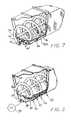
- FIG. 1is a perspective view of an auger conveyor according to the present invention showing a portion of a helical tube auger included in the conveyor in broken lines. FIG. 1 .
- FIG. 2is an enlarged partially broken away end view of the conveyor shown in
- FIG. 3is an end view of the conveyor of FIG. 1 , with the trough outer wall partially broken away and showing further details of a coolant flow tubing installation for the trough.
- FIG. 4is an end view of the conveyor with the outer wall broken away showing another form of coolant flow tubing installation for the trough.
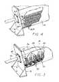
- FIG. 5is a perspective partially fragmentary view of another embodiment of the conveyor according to the present invention.
- FIG. 6is an enlarged fragmentary perspective view of one end of the conveyor shown in FIG. 5 with the outer wall of the trough partially broken away.
- FIG. 7is an enlarged perspective view of the end of the conveyor shown in FIG. 5 with both walls of the trough partially broken away to show the helical tube auger.
- FIG. 8is a fragmentary perspective view of the helical tube auger shown in FIG. 7 with a single wear plate shown in solid lines and a phantom line depiction of the entire series of wear plates.
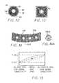
- FIG. 9is an enlarged transverse section taken across the helical tube auger and clamp on pusher blade of the type shown in FIG. 7 .
- FIG. 10is an enlarged transverse sectional view across a square section form of the helical tube auger.
- FIG. 11is an enlarged transverse sectional view of a trough coolant tube of the type shown in FIG. 7 .
- FIG. 12is a sectional view of an inner round tube nested within a round outer tube using an interposed mass of beads as the heat transfer medium.
- FIG. 13shows an outer square tube having an inner tube carrying a heat transfer fluid, and with a mass of heat conductive beads interposed.
- FIG. 14shows a double walled conveyor trough having a mass of interposed beads as a heat transfer medium.
- FIG. 14Ais an enlarged view of the beads shown in FIG. 14 , flattened to increase the contact area and thereby increase the thermal conductivity of the medium.
- FIG. 15is a diagram showing the relationship between thermal conductivity and the void space defined within a mass of heat conductive beads.
- a conveyor 10which includes an inclined trough 12 provided with optional covers 14 installed along the top thereof except at a loading opening 16 .
- the trough 12is supported to be upwardly inclined by means of frame supports 18 , at either end.
- a discharge chute 22is at the upper end.
- a helically wound auger tube 24is disposed lengthwise in the trough 14 and rotated by a rotary drive 26 .
- a heat transfer liquidsuch as water used as a coolant is typically introduced at the discharge end through an axial inlet 32 and through a side inlet 34 , and exits outlets 28 , 30 at the lower end of the conveyor 10 .
- a source 34 A, 32 A of as a liquid coolantis respectively connected with each inlet 34 , 32 and a coolant recycler (such as cooling towers) may be connected with each outlet 28 , 30 .
- FIG. 2shows further details.
- U-shaped loops of fluid flow tubing 36are located between an inner trough wall 38 and an outer wall 40 .
- the inner wall 38typically would be made of heavy gauge metal to provide adequate structural support and durability as the conveyed material is in direct contact therewith and its weight supported thereby.
- the outer confining wall 40can be of lighter gauge sheet metal or even a material having openings therein allowing air circulation through the intervening space such as the mesh material 40 A indicated in FIG. 7 .
- the flow tube 36is supported by interposed pieces here comprised of a series of side by side transverse thin metal fins or plates 42 contacting limited areas of the tubing 36 on edge, the outside surface of the inner wall 38 and the inner surface of the outer wall 40 .
- interposed pieceshere comprised of a series of side by side transverse thin metal fins or plates 42 contacting limited areas of the tubing 36 on edge, the outside surface of the inner wall 38 and the inner surface of the outer wall 40 .
- liquid coolantdoes not directly contact the hottest structure, i.e., the inner wall 38 , but rather there is only an indirect heat conducting path comprised of the interposed pieces, i.e. the fins or plates 42 contacting limited areas on the flow tubes 36 .
- the total area of contact and thus the conductivity of the piecesmay be selected to allow conduction of heat into the liquid in the tubing 36 at a lower rate such as to 42 not result in boiling of the coolant liquid flowing within the tubing 36 .
- the fins or plates 42may extend between the inner wall longitudinally so that an air flow can optionally be blown through the space and over the fins or plates 42 , from an air source 39 .
- Cooling liquidmay also be circulated through the helical auger tube 24 introduced via a rotary fluid coupling 44 into a central support tube 46 rotated by the rotary drive 26 and supported by a rotary bearing 48 ( FIG. 1 ).
- Liquidis directed into the helical tube 24 via a radial support tube 50 mechanically attached to the support/drive tube 46 .
- the support tube 46is blocked so as to avoid circulation through the support tube 46 which would be overheated if the conveyed material was at a sufficiently high temperature, i.e., on the order of 1000° F. or higher.
- Outlet flowis directed out into a support tube 46 at the lower end of the conveyor.
- FIG. 3shows another view of the trough coolant flow tubing 36 showing the U-shaped loops of tubing 36 and outlet 30 , the loops extending transversely to the axis of rotation of the tube 24 , i.e., in circumferential directions, although occupying only a portion of the perimeter of the trough 12 .
- FIG. 4shows a variation in which coolant flow tube loops 36 A are arranged longitudinally, and the fins or plates 42 A are oriented transversely to the longitudinal axis of the conveyor 10 .
- FIG. 5shows another form of the conveyor 52 in which an inlet manifold 58 is connected to an inlet 60 at the upper end and an outlet manifold 54 is connected to an outlet 56 .
- a series of straight longitudinal flow tubes 62extend the length of the trough 64 in the space between an inner wall 66 and outer wall 68 .
- the tubes 62are supported on the inner wall 66 by interposed pieces composed of thin metal straight strips 70 and curved thin metal bar stand offs 72 ( FIG. 11 ).
- the fluiddoes not directly contact the hottest structure, i.e., the trough inner wall 66 , but rather has an interposed heat conductive connection thereto confined to a limited area of the tube 62 and wall 66 . This reduces the rate of heat transfer to prevent a loss of conductivity which would result from a heat transfer rate causing boiling of the cooling liquid.
- a series of wear plates 76are clamped on the pushing side of the auger tube 74 , edge to edge along the length of the helical tube 74 ( FIG. 8 ).
- This clamp-on constructionis used instead of a welded conventional attachment to reduce thermal stress and avoid structional failures.
- the hot granular material 80 being conveyedcould otherwise rapidly wear the tube 74 depending on the material characteristics, temperature, as well as the volume conveyed.
- FIG. 9shows details of the attachment clamps for the wear plates 76 which are preferably constructed of a material such as an Nichrome alloy which is wear resistant at elevated temperatures.
- a U-bolt 82passes through a clamping piece 84 and is secured by nuts 86 .
- a pair of opposing legs 88 , 90 on the wear plate 76 and clamping piece 84have cut outs mating with the auger tube 74 .
- FIG. 10shows a square section tube 74 A, such that a flat wear plate 76 A and clamping piece 84 A can be secured with the U-bolt 82 A and nuts 86 .
- Both forms of wear plates 76 and 76 Acan have an angled portion 94 to assist in effectively pushing the material by rotation of the auger tube 74 or 74 A.
- the clamp-on designavoids the problem of weld failure resulting from the high temperatures reached by the tube 74 when very hot material (1000 EF or higher) is conveyed.
- FIGS. 12-15illustrate the use of an interposed mass of beads as a conductive connection having minimal mechanical rigidity while providing a controlled conductivity heat transfer path to a liquid coolant tubing so as to avoid boiling of the liquid by a too high rate of transfer of heat into the tubing.
- a round tube 88 as(used for auger tube 24 ) receives a smaller diameter inner coolant circulating tube 90 .
- An intermediate spaceis filled with a mass of heat conducting beads or particles 92 to establish a heat transfer path which can be of a controlled conductivity by controlling the proportion of void space, in turn varying with the bead size.
- the type of bead materialwould be selected depending on the desired design parameters, but would typically be a durable thermally conductive material such as aluminum.
- the bead sizewould likewise be set to achieve the desired coefficient of thermal conductivity (see below).
- a series of centering webs 94should be provided to maintain the tubes centered with respect to each other while the space therebetween being loaded with the beads.
- FIG. 13allows a round inner tube 96 and square outer tube 98 and centering webs 100 .
- FIG. 14shows a portion of a trough inner wall 102 and outer wall 104 with an intervening space filled with a mass of beads 106 .
- Spacer webs 108are also provided. This is intended to produce a precisely controlled designed for thermal conductivity selected so as to not cause boiling of the coolant and to thereby avoid the resultant loss of heat transfer into the coolant due to the presence of water vapor and boundary layer effects.
- FIG. 14Ashows flattened particles or beads 106 A, which flattening reduces the void space and increases the contact area between the beads to increase the overall thermal conductivity of the medium.
- FIG. 15shows the relationship between the proportion of void space and thermal conductivity.
- the proper selection of the spherically shaped particlesinvolves diameter, material, and relative pipe sizes. If the space were filled with particles that would create a very large proportion of open spaces, this would approximate the conductivity of air filling the open spaces, and the thermal conductivity would therefore be very low. However, if the space were filled with very small particles with minimal void space, this would approach the thermal conductivity of a solid and the heat transfer rate would therefore be high, approaching that of the material of the beads. Somewhere between these two extremes is a void ratio that would be in line with the desired heat transfer characteristics.
Landscapes
- Engineering & Computer Science (AREA)
- Mechanical Engineering (AREA)
- General Engineering & Computer Science (AREA)
- Physics & Mathematics (AREA)
- Thermal Sciences (AREA)
- Life Sciences & Earth Sciences (AREA)
- Microbiology (AREA)
- Heat-Exchange Devices With Radiators And Conduit Assemblies (AREA)
- Screw Conveyors (AREA)
Abstract
Description
This application is a divisional of U.S. Ser. No. 11/140,694 filed on May 31, 2005, which is a continuation-in-part of U.S. patent application Ser. No. 10/134,993 filed on Apr. 29, 2002 which claims the benefit of U.S. provisional application S.N. 60/586,685 filed on Jul. 9, 2004.
This invention concerns methods and arrangements for liquid cooling of structures contacting very hot materials which prevent the development of excessively high temperatures in the structure which can cause mechanical failures due to thermal stress. In conventional liquid cooling, liquid coolant typically flows through vessels in contact with the structures and a loss of cooling capacity may occur if the liquid coolant flowing in coolant vessels associated with the structures boils. This is a particular problem in conveyors such as auger or re-circulating chain flight conveyors used to convey very hot crushed or granular material exceeding 1000 EF through troughs such as in cement plants, lime kilns, power plants, etc.
Conveyors for such very hot materials have in the past had short service lives and were prone to failure. This is because of the effect of the high temperatures reached by the conveyor components as a result of conduction of heat from the conveyed material into the structure and components. Such conveyors have sometimes incorporated liquid cooling jackets within the conveyor trough along which the hot material is conveyed as by an auger extending along the length of the trough. In the past, the trough and jacket have been constructed as a weldment, and since the liquid cooled liner is in direct contact with the hot material conveyed, the welds are severely stressed by gross thermal expansions and contractions.
The resulting expansion and contraction of the trough and coolant jacket leads to cracking, buckling, weld failures and similar structural failures. If very hot material is conveyed (1000 EF or higher), cooling liquid in direct contact with the cooling jacket wall is heated to boiling, so that vapor is generated in the jacket, greatly reducing the rate of heat conduction into the cooling liquid.
The high heat flux boiling that is encountered, usually has regions of unstable film boiling which causes a thermal shock in the structure surface, which in turn can cause plastic mechanical behavior. This can lead to premature failure and has been studied mathematically and experimentally. See Kappila, R. W., “A Boiler Tube Problem, Elastic-Plastic Behavior of a Thick-Walled Cylinder Caused By Sinusoidal Inside Surface Temperature, Internal Heat Generation, and External Heat Flux,” PhD Dissertation, University of Michigan, 1968.
Since the trough cooling jacket is constructed as a weldment, it often is not designed or approved for use as a pressure vessel, allowing only very low coolant pressures and thus low flow rates imposing a substantial limitation on the rate of heat removal.
Similarly, conveying augers have also often been constructed as a weldment, with a central tube having radial spokes welded to a central tube forming a triangular cavity. Liquid coolant has sometimes been circulated through such an auger, with direct contact of the coolant with the metal auger which in turn is in direct contact with the hot material conveyed, leading to the same problems described above in connection with the conveyor trough.
Direct air cooling of the hot material requires dust collection equipment and baghouses and necessitates government permits, as pollutants may be mixed with the exhausted cooling air.
Many other industrial applications and high technology projects experience such difficulties, such as, screw conveyors in hot quick lime production, power plant hot clinker removal, hot surfaces of space vehicles during re-entry into the earth=s atmosphere, cooling high temperature engines and jets, boilers, etc.
It is an object of the present invention to provide arrangements and methods to control heat transfer into a liquid coolant within a flow vessel used to cool a hot material of the type described, in which direct contact of a liquid coolant with the structure holding the hot material is avoided.
It is a further object to provide a conveyor for hot material which avoids the use of weldments to mount parts subjected to thermal stresses induced by a large temperature differential between connected parts of the conveyor.
The above objects as well as other objects which will be understood upon a reading of the following specification and claims are achieved by a heat transfer arrangement including a connection between a coolant flow vessel and an inner wall structure to be cooled in which a desired controlled rate of heat transfer may be easily achieved to limit the rate of heat transfer to a predetermined level. This heat transfer arrangement connection may comprise a plurality of spaced apart stand off supports spacing the coolant vessel from the structure to be cooled. The stand off support crates a limited conductive heat transfer path between the structure to be cooled and the coolant vessel.
The stand offs may be comprised of an array of thin webs in contact with the inner wall and extending to the coolant vessel and outer wall.
As a preferred alternative, a mass of heat conductive beads of a predetermined size and configuration maybe confined in a space between the structure to be cooled and a coolant vessel as by an outer wall.
In one application of the invention, a conveyor including a trough along which hot material is conveyed, has separate liquid flow vessels passing over but spaced from an outside surface of the trough wall. The flow vessels are supported on the outer surface of the inner trough wall by heat conducting standoff supports such as interposed thin metal strips, angled metal strips or curved thin metal standoffs. A mass of conductive beads or particles may alternatively be provided, filling the space between the outer surface of the inner trough wall and the inner surface of an outer confining wall located beyond the coolant flow vessels.
Optionally, air flow can also be drawn in through openings in the outer wall and directed over the liquid flow vessels, and through the fins or beads to enhance cooling of the same.
The coolant liquid flow vessels can be arranged in longitudinal or transverse loops or longitudinally extending straight sections, and may supplied with a cooling liquid from a manifold at one end of the conveyor trough.
A helical auger tube mounted within the conveyor trough may have a side by side series of radially extending clamp-on wear plates of a durable material can be installed on the pushing side of the helical auger tube to prevent excessive wearing of the auger tube. The clamped attachment construction avoids thermally stressed welds. Optionally, a cooling fluid can also be circulated through the helical auger tube, or a second tube can be inserted in a larger outer helical tube with a series of metal strips or a mass of heat conductive beads, conducting the heat between the outer tube and the heat transfer liquid in the inner tube.
The arrangement of a mass of heat conductive beads, i.e., particles, in the space between a hot structure and a cooling structure provide a solution to excessive thermal stress and coolant boiling problems with minimum mechanical stiffness. In particular, the use of heat conductive particles interposed between the hot and cool surfaces such as a tube containing cooling water inside of a larger tube exposed to the high temperatures allows a precisely controlled rate of heat transfer therebetween. If the particles are spherical in shape, the mechanical stiffness of the medium is minimal and thermally induced stresses are avoided, furthermore, the contact area between the particles is also small to restrict the amount of heat being conducted through the mass of particles. If smaller size particles are used, the void ratio or open space is reduced which increases the contact area and the thermal conductance of the medium.
If the particle surfaces are flattened and made to fit adjoining particle surfaces, the contact area is farther increased and more heat is conducted. If the particles were shaped to be matched or complementary to each other perfectly with no void space, the medium is compact and approaches the heat transfer characteristic of a solid, except that the mechanical stiffness is still very small and the thermal stresses are minimized.
Use a material of a higher or lower thermal conductivity to construct the beads also allows a variation in overall thermal conductivity. Thus the thermal conductivity can be closely controlled to achieve a precisely predetermined heat transfer rate to suite a particular application.
In the following detailed description, certain specific terminology will be employed for the sake of clarity and a particular embodiment described in accordance with the requirements of 35 USC 112, but it is to be understood that the same is not intended to be limiting and should not be so construed inasmuch as the invention is capable of taking many forms and variations within the scope of the appended claims.
Referring to the drawings and particularlyFIG. 1 , aconveyor 10 is shown which includes aninclined trough 12 provided withoptional covers 14 installed along the top thereof except at a loading opening16.
Thetrough 12 is supported to be upwardly inclined by means of frame supports18, at either end.
Adischarge chute 22 is at the upper end. A helically woundauger tube 24 is disposed lengthwise in thetrough 14 and rotated by arotary drive 26. A heat transfer liquid such as water used as a coolant is typically introduced at the discharge end through anaxial inlet 32 and through aside inlet 34, and exitsoutlets conveyor 10.
A source34A,32A of as a liquid coolant is respectively connected with eachinlet outlet
Theflow tube 36 is supported by interposed pieces here comprised of a series of side by side transverse thin metal fins orplates 42 contacting limited areas of thetubing 36 on edge, the outside surface of theinner wall 38 and the inner surface of theouter wall 40. Thus, liquid coolant does not directly contact the hottest structure, i.e., theinner wall 38, but rather there is only an indirect heat conducting path comprised of the interposed pieces, i.e. the fins orplates 42 contacting limited areas on theflow tubes 36.
The total area of contact and thus the conductivity of the pieces may be selected to allow conduction of heat into the liquid in thetubing 36 at a lower rate such as to42 not result in boiling of the coolant liquid flowing within thetubing 36. The fins orplates 42 may extend between the inner wall longitudinally so that an air flow can optionally be blown through the space and over the fins orplates 42, from anair source 39.
Cooling liquid may also be circulated through thehelical auger tube 24 introduced via arotary fluid coupling 44 into acentral support tube 46 rotated by therotary drive 26 and supported by a rotary bearing48 (FIG. 1 ).
Liquid is directed into thehelical tube 24 via aradial support tube 50 mechanically attached to the support/drive tube 46. Thesupport tube 46 is blocked so as to avoid circulation through thesupport tube 46 which would be overheated if the conveyed material was at a sufficiently high temperature, i.e., on the order of 1000° F. or higher. Outlet flow is directed out into asupport tube 46 at the lower end of the conveyor.
As shown inFIG. 7 , thetubes 62 are supported on theinner wall 66 by interposed pieces composed of thin metal straight strips70 and curved thin metal bar stand offs72 (FIG. 11 ).
Thus, the fluid does not directly contact the hottest structure, i.e., the troughinner wall 66, but rather has an interposed heat conductive connection thereto confined to a limited area of thetube 62 andwall 66. This reduces the rate of heat transfer to prevent a loss of conductivity which would result from a heat transfer rate causing boiling of the cooling liquid.
In order to reduce abrasion wear of theauger tube 74, a series ofwear plates 76 are clamped on the pushing side of theauger tube 74, edge to edge along the length of the helical tube74 (FIG. 8 ). This clamp-on construction is used instead of a welded conventional attachment to reduce thermal stress and avoid structional failures.
The hotgranular material 80 being conveyed could otherwise rapidly wear thetube 74 depending on the material characteristics, temperature, as well as the volume conveyed.
A U-bolt82 passes through aclamping piece 84 and is secured by nuts86.
A pair of opposinglegs wear plate 76 and clampingpiece 84 have cut outs mating with theauger tube 74.
Both forms ofwear plates portion 94 to assist in effectively pushing the material by rotation of theauger tube tube 74 when very hot material (1000 EF or higher) is conveyed.
A series of centeringwebs 94 should be provided to maintain the tubes centered with respect to each other while the space therebetween being loaded with the beads.
Large diameter, spherical beads will conduct the heat while still allowing relative movement as induced by differing coefficients of thermal expansion of the adjacent structures without causing excessive stresses. Beads or particles of other regular shapes or irregular shapes could be selected that serve the same basic purpose of controlling thermal conductivity.
The proper selection of the spherically shaped particles involves diameter, material, and relative pipe sizes. If the space were filled with particles that would create a very large proportion of open spaces, this would approximate the conductivity of air filling the open spaces, and the thermal conductivity would therefore be very low. However, if the space were filled with very small particles with minimal void space, this would approach the thermal conductivity of a solid and the heat transfer rate would therefore be high, approaching that of the material of the beads. Somewhere between these two extremes is a void ratio that would be in line with the desired heat transfer characteristics. By properly selecting the particle sizes and material, and the overall geometry of the thermal screw, a design may be achieved which reduces thermal stresses to a level where structural problems are avoided, and sufficient material cooling is accomplished.
It should be noted that with proper design, forces due to dimensional changes from thermal effects, as well as thermal stresses cause by thermal gradients within structural members may be effectively controlled.
Claims (8)
1. A method of establishing a heat transfer path into a liquid coolant flow vessel separate from a heated hot structure to be cooled comprising interposing and packing together in contact a mass of heat conducting particles between said heated hot structure and said liquid coolant flow vessel, and sizing said particles to create sufficient open spaces between said particles to create an overall combined thermal conductivity of said packed together mass of particles and said open spaces such that the heat transfer rate into liquid coolant in said coolant vessel from said heated hot structure at the temperature of said heated structure is moderated to be below a level which would cause boiling of said liquid coolant flowing in said flow vessel.
2. The method according toclaim 1 further including shaping said particles to be substantially spherical, said contacting particles defining the size of said open spaces.
3. The method according toclaim 1 further including shaping said particles to be partially flattened and packed together to have flattened sides in contact with each other.
4. The method according toclaim 1 wherein said particles comprise metal beads which are packed into a confining space containing said flow vessel.
5. The method according toclaim 4 wherein said open spaces are filled with air such that said overall conductivity of said packed together particles and open spaces is defined in part by the thermal conductivity of air.
6. The method according toclaim 1 wherein said open spaces are filled with air such that said overall conductivity of said packed together particles and open spaces is defined in part by the thermal conductivity of air.
7. The method according toclaim 1 wherein said heated structure is formed in a trough shape to define a conveyor cavity receiving hot material at a temperature of about 1000° F. or greater which causes said structure to be heated by the presence of said hot material.
8. The method according toclaim 1 wherein said mass of particles surrounds said liquid coolant flow vessel to provide a non rigid mechanical support of said flow vessel.
Priority Applications (1)
| Application Number | Priority Date | Filing Date | Title |
|---|---|---|---|
| US12/583,328US8579014B2 (en) | 2002-04-29 | 2009-08-18 | Cooling arrangement for conveyors and other applications |
Applications Claiming Priority (4)
| Application Number | Priority Date | Filing Date | Title |
|---|---|---|---|
| US10/134,993US20040055738A1 (en) | 2002-04-29 | 2002-04-29 | Conveyor with heat transfer arrangement |
| US58668504P | 2004-07-09 | 2004-07-09 | |
| US11/140,694US7575043B2 (en) | 2002-04-29 | 2005-05-31 | Cooling arrangement for conveyors and other applications |
| US12/583,328US8579014B2 (en) | 2002-04-29 | 2009-08-18 | Cooling arrangement for conveyors and other applications |
Related Parent Applications (1)
| Application Number | Title | Priority Date | Filing Date |
|---|---|---|---|
| US11/140,694DivisionUS7575043B2 (en) | 2002-04-29 | 2005-05-31 | Cooling arrangement for conveyors and other applications |
Publications (2)
| Publication Number | Publication Date |
|---|---|
| US20100059205A1 US20100059205A1 (en) | 2010-03-11 |
| US8579014B2true US8579014B2 (en) | 2013-11-12 |
Family
ID=46304651
Family Applications (2)
| Application Number | Title | Priority Date | Filing Date |
|---|---|---|---|
| US11/140,694Expired - Fee RelatedUS7575043B2 (en) | 2002-04-29 | 2005-05-31 | Cooling arrangement for conveyors and other applications |
| US12/583,328Expired - Fee RelatedUS8579014B2 (en) | 2002-04-29 | 2009-08-18 | Cooling arrangement for conveyors and other applications |
Family Applications Before (1)
| Application Number | Title | Priority Date | Filing Date |
|---|---|---|---|
| US11/140,694Expired - Fee RelatedUS7575043B2 (en) | 2002-04-29 | 2005-05-31 | Cooling arrangement for conveyors and other applications |
Country Status (1)
| Country | Link |
|---|---|
| US (2) | US7575043B2 (en) |
Cited By (2)
| Publication number | Priority date | Publication date | Assignee | Title |
|---|---|---|---|---|
| US20140096933A1 (en)* | 2011-06-07 | 2014-04-10 | Commissariat A L'energie Atomique Et Aux Ene Alt | Reactive solid/heat-transport gas reactor including a helical duct in which the solid and the gas flow in opposite directions |
| US20240155808A1 (en)* | 2022-11-04 | 2024-05-09 | Amulaire Thermal Technology, Inc. | Two-phase immersion-cooling heat-dissipation composite structure having high-porosity solid structure and high-thermal-conductivity fins |
Families Citing this family (13)
| Publication number | Priority date | Publication date | Assignee | Title |
|---|---|---|---|---|
| US7575043B2 (en)* | 2002-04-29 | 2009-08-18 | Kauppila Richard W | Cooling arrangement for conveyors and other applications |
| NZ568435A (en)* | 2005-12-05 | 2011-02-25 | Gordon Craig Boots | Method and apparatus for processing of materials with bearings supporting rotating drum being sealed from heat and pressure added in interstitial space |
| US20090233375A1 (en)* | 2008-03-07 | 2009-09-17 | Jarvis Richard A | Thermal bath systems and thermally-conductive particulate thermal bath media and methods |
| WO2010027518A2 (en)* | 2008-03-07 | 2010-03-11 | Richard Jarvis | Thermal systems using thermally-conductive particulate thermal media and methods |
| JP5718028B2 (en)* | 2010-11-18 | 2015-05-13 | 古河電気工業株式会社 | Double pipe |
| US9462895B2 (en)* | 2011-12-08 | 2016-10-11 | Mixmo AB | Dispensing device |
| CA3064768C (en)* | 2017-05-26 | 2022-11-29 | Novelis Inc. | Decoating system comprising a cooled conveyor |
| US10845120B1 (en) | 2018-03-01 | 2020-11-24 | Steve Macchio | Systems and methods for environmentally-clean thermal drying |
| CN108613539B (en)* | 2018-04-02 | 2020-09-04 | 广德美好包装科技有限公司 | A heat exchange system of a heat recovery switch |
| US11441850B2 (en)* | 2020-01-24 | 2022-09-13 | Hamilton Sundstrand Corporation | Integral mounting arm for heat exchanger |
| US11703283B2 (en) | 2020-01-24 | 2023-07-18 | Hamilton Sundstrand Corporation | Radial configuration for heat exchanger core |
| US11460252B2 (en) | 2020-01-24 | 2022-10-04 | Hamilton Sundstrand Corporation | Header arrangement for additively manufactured heat exchanger |
| US11453160B2 (en) | 2020-01-24 | 2022-09-27 | Hamilton Sundstrand Corporation | Method of building a heat exchanger |
Citations (186)
| Publication number | Priority date | Publication date | Assignee | Title |
|---|---|---|---|---|
| US360971A (en) | 1887-04-12 | butler | ||
| US608755A (en)* | 1898-08-09 | District of co | ||
| US965391A (en)* | 1908-12-30 | 1910-07-26 | Mary L Little | Solar-heating plant. |
| GB264670A (en) | 1926-02-11 | 1927-01-27 | Norman Isherwood | Improvements in calender rollers or drying cylinders |
| US1698313A (en) | 1927-03-04 | 1929-01-08 | Firm G Polysius | Device for utilizing the heat radiated from kilns |
| US1716333A (en)* | 1916-10-14 | 1929-06-04 | Safety Car Heating & Lighting | Heat-exchange apparatus |
| US1792769A (en) | 1930-03-29 | 1931-02-17 | George B Schmidt | Feather drier |
| US1953342A (en)* | 1932-10-11 | 1934-04-03 | Adolph L Foell | Checkerwork construction |
| US2036068A (en)* | 1934-11-22 | 1936-03-31 | Gen Electric | Liquid immersed electrical apparatus |
| US2401797A (en)* | 1943-12-27 | 1946-06-11 | Gen Motors Corp | Heat exchanger |
| US2431455A (en)* | 1943-12-24 | 1947-11-25 | Standard Oil Dev Co | Contacting liquids with gaseous fluids in the presence of solid particles |
| US2525261A (en)* | 1946-09-30 | 1950-10-10 | James P Henderson | Refrigerated ball dispenser |
| US2616668A (en)* | 1947-05-30 | 1952-11-04 | Hartford Nat Bank & Trust Co | Regenerator |
| US2898091A (en)* | 1956-09-27 | 1959-08-04 | Philips Corp | Thermal regenerator |
| US2908486A (en) | 1955-07-07 | 1959-10-13 | Us Rubber Co | Heat exchange roll |
| GB825075A (en) | 1956-10-23 | 1959-12-09 | Bauermeister Hermann Maschf | Improvements in or relating to hollow rollers |
| US3049799A (en)* | 1958-07-28 | 1962-08-21 | Union Carbide Corp | Method of gas plating |
| US3094397A (en) | 1960-09-28 | 1963-06-18 | Olin Mathieson | Rotary dryer |
| US3135044A (en)* | 1959-06-04 | 1964-06-02 | United Aircraft Corp | Lightwight porous structures and methods of making same |
| US3144905A (en) | 1960-11-15 | 1964-08-18 | Albert William | Roll construction |
| US3153279A (en)* | 1959-05-29 | 1964-10-20 | Horst Corp Of America V D | Heat resistant solid structure |
| US3161478A (en)* | 1959-05-29 | 1964-12-15 | Horst Corp Of America V D | Heat resistant porous structure |
| US3235972A (en)* | 1962-01-18 | 1966-02-22 | British Paper And Board Indust | Method and apparatus for drying of paper, board or pulp webs, formed from cellulosicfibrous material |
| US3289756A (en)* | 1964-10-15 | 1966-12-06 | Olin Mathieson | Heat exchanger |
| US3295591A (en)* | 1965-09-09 | 1967-01-03 | Harry E Thomason | Apparatus for cooling and solar heating a house |
| US3306353A (en)* | 1964-12-23 | 1967-02-28 | Olin Mathieson | Heat exchanger with sintered metal matrix around tubes |
| US3331435A (en)* | 1965-10-11 | 1967-07-18 | Olin Mathieson | Heat exchanger with sintered metal matrix |
| US3369541A (en)* | 1965-10-22 | 1968-02-20 | Harry E. Thomason | Heat storage |
| US3384557A (en)* | 1964-07-21 | 1968-05-21 | Fmc Corp | Method of curing of green briquettes by oxidation |
| US3513908A (en)* | 1967-08-18 | 1970-05-26 | Guru B Singh | Embedded tube heat exchanger |
| US3580389A (en) | 1968-01-25 | 1971-05-25 | Metallgesellschaft Ag | Screw conveyor |
| US3587730A (en)* | 1956-08-30 | 1971-06-28 | Union Carbide Corp | Heat exchange system with porous boiling layer |
| US3596713A (en)* | 1969-01-27 | 1971-08-03 | Astro Dynamics Inc | Liquid-solid heat transport system |
| US3607086A (en) | 1970-02-24 | 1971-09-21 | George W Dingus | Apparatus for wet-pelletizing carbon black |
| US3621905A (en)* | 1969-02-10 | 1971-11-23 | Nordstjernan Rederi Ab | Method of improving the heat transport in a tube of an evaporator or other cooking apparatus |
| US3627036A (en) | 1970-01-29 | 1971-12-14 | William W Gilbert | Heat exchange system |
| US3637069A (en) | 1968-05-21 | 1972-01-25 | Packaged Power Terminals Inc | Screw conveyor apparatus |
| US3645237A (en)* | 1970-06-10 | 1972-02-29 | American Standard Inc | Water heater having fluidized bed combustion and heat exchange region |
| US3666006A (en)* | 1970-05-04 | 1972-05-30 | Olin Corp | Heat exchanger |
| US3670276A (en)* | 1971-02-11 | 1972-06-13 | Ltv Ling Altec Inc | Hermetic transformer |
| US3698541A (en) | 1971-08-11 | 1972-10-17 | Midland Ross Corp | Extruder, or extruder-like melting apparatus |
| US3704748A (en)* | 1970-02-11 | 1972-12-05 | Ratheon Co | Heat transfer structure |
| US3732919A (en)* | 1970-07-01 | 1973-05-15 | J Wilson | Heat exchanger |
| US3753757A (en)* | 1970-05-15 | 1973-08-21 | Union Carbide Corp | Two step porous boiling surface formation |
| US3762026A (en)* | 1963-01-08 | 1973-10-02 | Nuclear Materials And Equip Co | Method of making a high temperature body of uniform porosity |
| US3773031A (en)* | 1968-09-09 | 1973-11-20 | Laing Nikolaus | Device for storing heat or cold |
| US3775041A (en)* | 1972-05-10 | 1973-11-27 | H Buttner | Recirculating ball heat transfer system for drying and heating materials |
| US3802551A (en) | 1971-02-17 | 1974-04-09 | S Somers | Flexible tubular conveyor |
| US3808988A (en) | 1972-10-20 | 1974-05-07 | M Sugano | Apparatus for supplying air into combustion chamber of rotary kiln incinerator |
| US3821018A (en)* | 1969-10-10 | 1974-06-28 | Union Carbide Corp | Porous metallic layer formation |
| US3822651A (en) | 1973-09-04 | 1974-07-09 | D Harris | Water cooled kiln for waste disposal |
| US3884772A (en)* | 1971-09-25 | 1975-05-20 | Furukawa Electric Co Ltd | Method for producing a heat exchanger element |
| US3885529A (en)* | 1970-03-02 | 1975-05-27 | American Standard Inc | Heat exchanger structure for a compact boiler and the like |
| US3887672A (en)* | 1971-11-04 | 1975-06-03 | Basf Ag | Manufacture of saddle-shaped discs from expandable styrene polymers |
| US3894685A (en)* | 1974-02-25 | 1975-07-15 | Int Solarthermics Corp | Solar heating system |
| US3921712A (en)* | 1970-03-02 | 1975-11-25 | American Standard Inc | Heat exchanger structure for a compact boiler and the like |
| US3960203A (en)* | 1971-04-29 | 1976-06-01 | Titanium Technology N.V. | Fluidized bed cooler |
| US3973718A (en)* | 1973-06-06 | 1976-08-10 | Deschamps Laboratories, Inc. | Method of manufacturing a heat exchanger core |
| US3981151A (en)* | 1975-01-20 | 1976-09-21 | St Clair John C | Use of solar energy heat gathering and storing systems to increase farm crop yields |
| US3990862A (en)* | 1975-01-31 | 1976-11-09 | The Gates Rubber Company | Liquid heat exchanger interface and method |
| US3995181A (en)* | 1975-06-13 | 1976-11-30 | Sundstrand Corporation | Matrix for enhancing the flow of coolant through an alternator stator |
| US3998188A (en) | 1971-04-13 | 1976-12-21 | Beverley Chemical Engineering Company, Ltd. | Heater for heating a fluid |
| US4050897A (en) | 1972-06-26 | 1977-09-27 | Normac, Inc. | Reactor apparatus |
| US4051891A (en)* | 1975-10-01 | 1977-10-04 | Halm Instrument Co., Inc. | Heat transfer block means |
| US4063589A (en)* | 1974-03-21 | 1977-12-20 | Coal Industry (Patents) Limited | Heat exchanger assemblies |
| US4078392A (en)* | 1976-12-29 | 1978-03-14 | Borg-Warner Corporation | Direct contact heat transfer system using magnetic fluids |
| US4104883A (en)* | 1977-05-27 | 1978-08-08 | The United States Of America As Represented By The Secretary Of The Navy | Mass transport heat exchanger method and apparatus for use in ocean thermal energy exchange power plants |
| US4109702A (en)* | 1976-08-06 | 1978-08-29 | Greene Norman Donald | Energy storage and retrieval as heat |
| US4124357A (en)* | 1977-04-28 | 1978-11-07 | Toyota Jidosha Kogyo Kabushiki Kaisha | Catalytic converter of a radial flow type |
| US4126177A (en) | 1977-03-10 | 1978-11-21 | Chemetron Corporation | Dual scraped surface heat exchanger |
| US4127973A (en)* | 1977-03-30 | 1978-12-05 | James Kachadorian | Solar-heated concrete slab building structure |
| US4129181A (en)* | 1977-02-16 | 1978-12-12 | Uop Inc. | Heat transfer surface |
| US4142576A (en)* | 1976-08-27 | 1979-03-06 | Electric Power Research Institute, Inc. | Heat pump system with improved heat transfer |
| US4180718A (en) | 1976-09-10 | 1979-12-25 | Lester Hanson | Apparatus and system for processing oil shale |
| US4182412A (en)* | 1978-01-09 | 1980-01-08 | Uop Inc. | Finned heat transfer tube with porous boiling surface and method for producing same |
| US4187831A (en)* | 1978-06-21 | 1980-02-12 | Eubank Marcus P | Self contained solar heating supplemental unit |
| US4205656A (en)* | 1978-06-06 | 1980-06-03 | Scarlata Robert W | Thermal storage reservoirs |
| US4207943A (en) | 1979-03-28 | 1980-06-17 | Oros Company | Countercurrent solid-to-solid heat transfer apparatus and method |
| US4219075A (en)* | 1977-05-04 | 1980-08-26 | Ingeborg Laing | Heat storage device |
| US4227567A (en)* | 1978-12-21 | 1980-10-14 | Kohler Co. | Intermediate temperature, heat storage and retrieval system |
| US4257478A (en)* | 1979-06-27 | 1981-03-24 | Stal-Laval Apparat Ab | Gaseous media heat exchanger |
| US4258783A (en)* | 1977-11-01 | 1981-03-31 | Borg-Warner Corporation | Boiling heat transfer surface, method of preparing same and method of boiling |
| US4260371A (en) | 1979-07-20 | 1981-04-07 | Shale Oil Science & Systems, Inc. | Modular heat exchange apparatus |
| US4262485A (en)* | 1977-12-02 | 1981-04-21 | Hitachi, Ltd. | Low boiling point medium power plant |
| US4273101A (en)* | 1978-06-13 | 1981-06-16 | Messerschmitt-Bolkow-Blohm Gmbh | Solar energy system |
| US4286650A (en)* | 1978-06-16 | 1981-09-01 | Deutsche Forschungs- und Versuchsanstalt fur Luft- und Roumfabert e.V. | Method for charging or discharging a heat accumulator |
| US4291758A (en)* | 1978-10-31 | 1981-09-29 | Mitsubishi Denki Kabushiki Kaisha | Preparation of boiling heat transfer surface |
| US4323113A (en)* | 1980-10-31 | 1982-04-06 | Troyer Leroy S | Underground air tempering system |
| US4335785A (en)* | 1980-11-19 | 1982-06-22 | Hodges James L | Apparatus and method for controlling heat transfer between a fluidized bed and tubes immersed therein |
| US4343352A (en)* | 1979-04-09 | 1982-08-10 | A/S Norsk Viftefabrikk | Heat exchanger for gases |
| US4355627A (en)* | 1978-06-06 | 1982-10-26 | Scarlata Robert W | Thermal storage system |
| US4359086A (en)* | 1981-05-18 | 1982-11-16 | The Trane Company | Heat exchange surface with porous coating and subsurface cavities |
| US4360339A (en)* | 1981-02-02 | 1982-11-23 | Combustion Engineering, Inc. | Fluidized boiler |
| US4361182A (en)* | 1979-10-18 | 1982-11-30 | L. & C. Steinmuller Gmbh | Heat-transferring elements for regenerative heat exchange |
| US4367589A (en) | 1979-10-05 | 1983-01-11 | Joachim Mainka | Drafting machine head |
| US4381818A (en)* | 1977-12-19 | 1983-05-03 | International Business Machines Corporation | Porous film heat transfer |
| US4384463A (en) | 1981-07-23 | 1983-05-24 | Franrica Mfg. Inc. | Flexible bag cooling arrangement |
| US4405010A (en)* | 1978-06-28 | 1983-09-20 | Sanders Associates, Inc. | Sensible heat storage unit |
| US4408659A (en)* | 1980-10-14 | 1983-10-11 | L. & C. Steinmuller Gmbh | Heat storage mass for regenerative heat exchange |
| US4418683A (en)* | 1981-04-23 | 1983-12-06 | Rockwell International Corporation | Separated phase thermal storage system |
| US4437315A (en) | 1981-07-23 | 1984-03-20 | Franrica Mfg. Inc. | Flexible bag cooling arrangement |
| US4439141A (en)* | 1982-05-05 | 1984-03-27 | Deckebach George J | Recuperative double chamber rotary furnace |
| US4446916A (en)* | 1981-08-13 | 1984-05-08 | Hayes Claude Q C | Heat-absorbing heat sink |
| US4458748A (en)* | 1979-01-18 | 1984-07-10 | Hisaka Works, Limited | Plate type evaporator |
| US4499944A (en)* | 1982-02-18 | 1985-02-19 | Tokyo Shibaura Denki Kabushiki Kaisha | Heat exchangers installed in fluidized beds |
| US4509584A (en)* | 1982-04-16 | 1985-04-09 | Apparatebau Rothemuhle Brandt & Kritzler Gmbh | Heat-transferring elements for regenerative heat exchange in gas-gas fluidized bed heat exchangers |
| US4515205A (en)* | 1981-10-26 | 1985-05-07 | General Electric Company | Method for fluidized particle tray heat exchange |
| US4520862A (en)* | 1982-02-11 | 1985-06-04 | Walter Helmbold | Energy storage apparatus |
| US4522252A (en)* | 1982-05-21 | 1985-06-11 | Esmil B.V. | Method of operating a liquid-liquid heat exchanger |
| US4531146A (en)* | 1983-07-14 | 1985-07-23 | Cutchaw John M | Apparatus for cooling high-density integrated circuit packages |
| US4537632A (en)* | 1983-10-19 | 1985-08-27 | Sermatech International, Inc. | Spherical aluminum particles in coatings |
| US4544020A (en)* | 1982-05-26 | 1985-10-01 | Creusot-Loire | Method of regulating the heat transfer coefficient of a heat exchanger and improved heat exchanger for practicing said method |
| US4544028A (en)* | 1983-04-20 | 1985-10-01 | C. Mitchell Bedford | Heat accumulator |
| US4565242A (en)* | 1981-03-13 | 1986-01-21 | Kubota Ltd. | Heat accumulating material enclosing container and heat accumulating apparatus |
| US4575010A (en)* | 1984-06-20 | 1986-03-11 | Zimmerman Harold M | Method and apparatus for spreading heated sand |
| US4593754A (en)* | 1980-06-24 | 1986-06-10 | Holl Richard A | Shell and tube heat transfer apparatus and process therefor |
| US4600052A (en)* | 1984-03-02 | 1986-07-15 | Southwest Research Institute | Compact heat exchanger |
| US4612978A (en)* | 1983-07-14 | 1986-09-23 | Cutchaw John M | Apparatus for cooling high-density integrated circuit packages |
| US4640339A (en)* | 1983-07-22 | 1987-02-03 | Esmil B.V. | Apparatus for carrying out physical and/or chemical processes, more specifically a heat exchanger of the continuous type |
| US4657067A (en)* | 1985-06-19 | 1987-04-14 | Ohio State University | Hypereutectic direct-contact thermal storage material and method of production thereof |
| US4659613A (en)* | 1983-12-29 | 1987-04-21 | Sermatech International, Inc. | Parts coated with thick coating compositions of uni- and polymodal types |
| US4663243A (en)* | 1982-10-28 | 1987-05-05 | Union Carbide Corporation | Flame-sprayed ferrous alloy enhanced boiling surface |
| US4693754A (en)* | 1982-09-20 | 1987-09-15 | Tom Kondis | Aluminum particles resistant to reaction with water |
| US4703749A (en)* | 1982-09-30 | 1987-11-03 | Morse Roger N | Solar apparatus |
| US4708198A (en)* | 1982-11-01 | 1987-11-24 | Holl Richard A | Construction and method for improving heat transfer and mechanical life of tube-bundle heat exchangers |
| US4724172A (en)* | 1983-12-29 | 1988-02-09 | Sermatech International, Inc. | Thick coating compositions |
| US4730665A (en)* | 1983-07-14 | 1988-03-15 | Technology Enterprises Company | Apparatus for cooling high-density integrated circuit packages |
| US4759404A (en)* | 1980-05-19 | 1988-07-26 | Henson H Keith | Heterodensity heat transfer apparatus and method |
| US4768579A (en)* | 1987-01-13 | 1988-09-06 | Jean Patry | Recipient design to contain an energy storage medium with high fusion-crystallization latent heat |
| US4770237A (en)* | 1984-04-20 | 1988-09-13 | Framatome & Cie. | Process for circulating solid particles within a fluidization chamber and fluidization chamber for carrying out the process |
| US4809771A (en)* | 1987-04-24 | 1989-03-07 | The United States Of America As Represented By The Secretary Of The Air Force | Lih thermal storage capsule/heat exchanger |
| US4823863A (en)* | 1986-03-20 | 1989-04-25 | Hitachi, Ltd. | Thermal conduction device |
| US4846676A (en) | 1987-03-31 | 1989-07-11 | General Kinematics Corporation | Oscillating discharge chute |
| US4865122A (en)* | 1988-05-16 | 1989-09-12 | Iowa State University Research Foundation, Inc. | Aggregatively fluidized liquid heat exchanger |
| US4880054A (en)* | 1987-02-02 | 1989-11-14 | Mitsubishi Denki Kabushiki Kaisha | Heat exchanger tube for evaporation or condensation |
| US4884169A (en)* | 1989-01-23 | 1989-11-28 | Technology Enterprises Company | Bubble generation in condensation wells for cooling high density integrated circuit chips |
| US4889060A (en) | 1989-01-27 | 1989-12-26 | Westinghouse Electric Corp. | Web for rotary combustor |
| US4890669A (en)* | 1986-07-02 | 1990-01-02 | Carrier Corporation | Porous coating for enhanced tubes |
| US4938409A (en)* | 1988-02-29 | 1990-07-03 | Nuclear Metals, Inc. | Brazed porous coating and improved method of joining metal with silver material |
| US4955942A (en)* | 1989-08-08 | 1990-09-11 | The United States Of America As Represented By The United States Department Of Energy | In-bed tube bank for a fluidized-bed combustor |
| US4981172A (en)* | 1988-08-20 | 1991-01-01 | Schwaebische Huettenwerke Gmbh | Mechanism for heat transfer |
| US4992245A (en)* | 1988-03-31 | 1991-02-12 | Advanced Silicon Materials Inc. | Annular heated fluidized bed reactor |
| US5000252A (en)* | 1990-02-22 | 1991-03-19 | Wright State University | Thermal energy storage system |
| US5060719A (en)* | 1988-12-15 | 1991-10-29 | Mobil Oil Corporation | Using fluidized particles |
| US5123480A (en)* | 1991-08-05 | 1992-06-23 | Riley Stoker Corporation | Integrated heat exchanger |
| JPH04369389A (en) | 1991-06-14 | 1992-12-22 | Bridgestone Corp | Drum, heating and cooling method for the drum, and heating and cooling method by use of the drum |
| US5227026A (en) | 1989-07-21 | 1993-07-13 | Hogan Jim S | Retort heat exchanger apparatus |
| US5239839A (en)* | 1991-06-17 | 1993-08-31 | James Timothy W | Thermal energy storage apparatus enabling use of aqueous or corrosive thermal storage media |
| US5277245A (en)* | 1992-10-29 | 1994-01-11 | Gte Products Corp. | Heat transfer in fluidized bed of cohesive powder |
| US5286951A (en)* | 1992-11-09 | 1994-02-15 | Jones Mark A | Acetate spectacle frame bridge adjuster |
| US5323294A (en)* | 1993-03-31 | 1994-06-21 | Unisys Corporation | Liquid metal heat conducting member and integrated circuit package incorporating same |
| US5323843A (en)* | 1992-08-05 | 1994-06-28 | Martin Marietta Energy Systems, Inc. | Lih thermal energy storage device |
| US5441097A (en)* | 1993-05-19 | 1995-08-15 | Chiyoda Corporation | Heat storage tank equipped with heat storage members and fabrication process for the same |
| US5542022A (en)* | 1993-07-01 | 1996-07-30 | Coal Tech Corp. | Compact packed bed heater system |
| US5651191A (en) | 1995-07-28 | 1997-07-29 | Wolverine Corporation | Material treatment system |
| US5687706A (en)* | 1995-04-25 | 1997-11-18 | University Of Florida | Phase change material storage heater |
| US5814392A (en)* | 1994-03-23 | 1998-09-29 | Board Of Regents, The University Of Texas System | Boiling enhancement coating |
| US5853045A (en)* | 1995-03-31 | 1998-12-29 | Patry; Jean | Accumulator-exchanger device |
| US5863197A (en) | 1997-04-25 | 1999-01-26 | The International Metals Reclamation Company, Inc. | Solid flight conveying screw for furnace |
| US5960863A (en)* | 1998-01-07 | 1999-10-05 | Hua; Hsu Mei | Dissipating device for computer chips |
| US6047767A (en) | 1998-04-21 | 2000-04-11 | Vita International, Inc. | Heat exchanger |
| US6105659A (en)* | 1996-09-12 | 2000-08-22 | Jaro Technologies, Inc. | Rechargeable thermal battery for latent energy storage and transfer |
| US6171691B1 (en)* | 1997-02-06 | 2001-01-09 | Sumitomo Electric Industries, Ltd. | Heat sink material for use with semiconductor component and method for fabricating the same, and semiconductor package using the same |
| US6263958B1 (en)* | 1998-02-23 | 2001-07-24 | William H. Fleishman | Heat exchangers that contain and utilize fluidized small solid particles |
| US6302188B1 (en)* | 1998-04-28 | 2001-10-16 | Megtec Systems, Inc. | Multi-layer heat exchange bed containing structured media and randomly packed media |
| US20030019613A1 (en)* | 2001-07-25 | 2003-01-30 | Fleischman William H. | Heat exchangers that contain and utilize fluidized small solid particles |
| US6547222B2 (en)* | 1999-08-17 | 2003-04-15 | Koch Knight, Llc | Packing element |
| US6638062B1 (en)* | 2002-09-13 | 2003-10-28 | Michael P. Davidson | Sand and stone screw heater |
| US6701742B2 (en)* | 1999-10-08 | 2004-03-09 | BSH Bosch und Siemens Hausgeräte GmbH | Heat exchanger, such as evaporator, condenser, or the like |
| US20040055738A1 (en)* | 2002-04-29 | 2004-03-25 | Kauppila Richard W. | Conveyor with heat transfer arrangement |
| US20040069455A1 (en)* | 2002-08-28 | 2004-04-15 | Lindemuth James E. | Vapor chamber with sintered grooved wick |
| US6772823B2 (en)* | 1999-02-23 | 2004-08-10 | Agency Of Industrial Science And Technology | Heat storage device |
| US6774482B2 (en)* | 2002-12-27 | 2004-08-10 | International Business Machines Corporation | Chip cooling |
| US6808631B2 (en)* | 2002-10-22 | 2004-10-26 | Rolf Paloheimo | Aerobic wastewater treatment apparatus |
| US6810945B1 (en)* | 2003-04-29 | 2004-11-02 | Mat Boissevain | Conditioning the air in a structure utilizing a gravel heat exchanger underneath the slab |
| US6896039B2 (en)* | 1999-05-12 | 2005-05-24 | Thermal Corp. | Integrated circuit heat pipe heat spreader with through mounting holes |
| US20050252636A1 (en)* | 2002-04-29 | 2005-11-17 | Kauppila Richard W | Cooling arrangement for conveyors and other applications |
| US7124809B2 (en)* | 2003-06-26 | 2006-10-24 | Thermal Corp. | Brazed wick for a heat transfer device |
| US20070035927A1 (en)* | 2004-06-16 | 2007-02-15 | Hakan Erturk | Heat dissipating device with enhanced boiling/condensation structure |
| US7364707B2 (en)* | 2001-10-25 | 2008-04-29 | Fluid Technologies (Environmental) Limited | Packing element comprising at least one recessed portion of specific volume and method of using thereof |
| US7618684B2 (en)* | 2002-12-12 | 2009-11-17 | Innovatech, Llc | Method of forming a coating on a surface of a substrate |
| US7690419B2 (en)* | 2003-10-20 | 2010-04-06 | Thermal Corp. | Porous media cold plate |
| US7849922B2 (en)* | 2007-04-20 | 2010-12-14 | Shell Oil Company | In situ recovery from residually heated sections in a hydrocarbon containing formation |
| US7993599B2 (en)* | 2006-03-03 | 2011-08-09 | Zeropoint Clean Tech, Inc. | Method for enhancing catalyst selectivity |
| US8191618B2 (en)* | 2004-02-04 | 2012-06-05 | Battelle Energy Alliance, Llc | Methods of forming thermal management systems and thermal management methods |
| US8230901B2 (en)* | 2005-11-30 | 2012-07-31 | Fujitsu Limited | Electronic device cooling apparatus |
Family Cites Families (6)
| Publication number | Priority date | Publication date | Assignee | Title |
|---|---|---|---|---|
| US3481720A (en)* | 1966-04-29 | 1969-12-02 | Sun Oil Co | Process and apparatus for the distillation of solids |
| US4285773A (en)* | 1977-08-27 | 1981-08-25 | Alberta Oil Sands Technology And Research Authority | Apparatus and process for recovery of hydrocarbon from inorganic host materials |
| AT380562B (en)* | 1979-06-25 | 1986-06-10 | Waagner Biro Ag | DRYING OR COOLING DEVICE FOR SCHUETTGUETER |
| DE3015290A1 (en)* | 1980-04-21 | 1981-10-29 | Werner & Pfleiderer, 7000 Stuttgart | METHOD AND SYSTEM FOR BURNING CLEANING SLUDGE |
| US4639217A (en)* | 1985-01-14 | 1987-01-27 | Adams D Carlos | Countercurrent heat transfer device for solid particle streams |
| US4846675A (en)* | 1987-06-01 | 1989-07-11 | Worthington Industries, Inc. | Annealing furnace |
- 2005
- 2005-05-31USUS11/140,694patent/US7575043B2/ennot_activeExpired - Fee Related
- 2009
- 2009-08-18USUS12/583,328patent/US8579014B2/ennot_activeExpired - Fee Related
Patent Citations (191)
| Publication number | Priority date | Publication date | Assignee | Title |
|---|---|---|---|---|
| US360971A (en) | 1887-04-12 | butler | ||
| US608755A (en)* | 1898-08-09 | District of co | ||
| US965391A (en)* | 1908-12-30 | 1910-07-26 | Mary L Little | Solar-heating plant. |
| US1716333A (en)* | 1916-10-14 | 1929-06-04 | Safety Car Heating & Lighting | Heat-exchange apparatus |
| GB264670A (en) | 1926-02-11 | 1927-01-27 | Norman Isherwood | Improvements in calender rollers or drying cylinders |
| US1698313A (en) | 1927-03-04 | 1929-01-08 | Firm G Polysius | Device for utilizing the heat radiated from kilns |
| US1792769A (en) | 1930-03-29 | 1931-02-17 | George B Schmidt | Feather drier |
| US1953342A (en)* | 1932-10-11 | 1934-04-03 | Adolph L Foell | Checkerwork construction |
| US2036068A (en)* | 1934-11-22 | 1936-03-31 | Gen Electric | Liquid immersed electrical apparatus |
| US2431455A (en)* | 1943-12-24 | 1947-11-25 | Standard Oil Dev Co | Contacting liquids with gaseous fluids in the presence of solid particles |
| US2401797A (en)* | 1943-12-27 | 1946-06-11 | Gen Motors Corp | Heat exchanger |
| US2525261A (en)* | 1946-09-30 | 1950-10-10 | James P Henderson | Refrigerated ball dispenser |
| US2616668A (en)* | 1947-05-30 | 1952-11-04 | Hartford Nat Bank & Trust Co | Regenerator |
| US2908486A (en) | 1955-07-07 | 1959-10-13 | Us Rubber Co | Heat exchange roll |
| US3587730A (en)* | 1956-08-30 | 1971-06-28 | Union Carbide Corp | Heat exchange system with porous boiling layer |
| US2898091A (en)* | 1956-09-27 | 1959-08-04 | Philips Corp | Thermal regenerator |
| GB825075A (en) | 1956-10-23 | 1959-12-09 | Bauermeister Hermann Maschf | Improvements in or relating to hollow rollers |
| US3049799A (en)* | 1958-07-28 | 1962-08-21 | Union Carbide Corp | Method of gas plating |
| US3161478A (en)* | 1959-05-29 | 1964-12-15 | Horst Corp Of America V D | Heat resistant porous structure |
| US3153279A (en)* | 1959-05-29 | 1964-10-20 | Horst Corp Of America V D | Heat resistant solid structure |
| US3135044A (en)* | 1959-06-04 | 1964-06-02 | United Aircraft Corp | Lightwight porous structures and methods of making same |
| US3094397A (en) | 1960-09-28 | 1963-06-18 | Olin Mathieson | Rotary dryer |
| US3144905A (en) | 1960-11-15 | 1964-08-18 | Albert William | Roll construction |
| US3235972A (en)* | 1962-01-18 | 1966-02-22 | British Paper And Board Indust | Method and apparatus for drying of paper, board or pulp webs, formed from cellulosicfibrous material |
| US3762026A (en)* | 1963-01-08 | 1973-10-02 | Nuclear Materials And Equip Co | Method of making a high temperature body of uniform porosity |
| US3384557A (en)* | 1964-07-21 | 1968-05-21 | Fmc Corp | Method of curing of green briquettes by oxidation |
| US3289756A (en)* | 1964-10-15 | 1966-12-06 | Olin Mathieson | Heat exchanger |
| US3306353A (en)* | 1964-12-23 | 1967-02-28 | Olin Mathieson | Heat exchanger with sintered metal matrix around tubes |
| US3295591A (en)* | 1965-09-09 | 1967-01-03 | Harry E Thomason | Apparatus for cooling and solar heating a house |
| US3331435A (en)* | 1965-10-11 | 1967-07-18 | Olin Mathieson | Heat exchanger with sintered metal matrix |
| US3369541A (en)* | 1965-10-22 | 1968-02-20 | Harry E. Thomason | Heat storage |
| US3513908A (en)* | 1967-08-18 | 1970-05-26 | Guru B Singh | Embedded tube heat exchanger |
| US3580389A (en) | 1968-01-25 | 1971-05-25 | Metallgesellschaft Ag | Screw conveyor |
| US3637069A (en) | 1968-05-21 | 1972-01-25 | Packaged Power Terminals Inc | Screw conveyor apparatus |
| US3773031A (en)* | 1968-09-09 | 1973-11-20 | Laing Nikolaus | Device for storing heat or cold |
| US3596713A (en)* | 1969-01-27 | 1971-08-03 | Astro Dynamics Inc | Liquid-solid heat transport system |
| US3621905A (en)* | 1969-02-10 | 1971-11-23 | Nordstjernan Rederi Ab | Method of improving the heat transport in a tube of an evaporator or other cooking apparatus |
| US3821018A (en)* | 1969-10-10 | 1974-06-28 | Union Carbide Corp | Porous metallic layer formation |
| US3627036A (en) | 1970-01-29 | 1971-12-14 | William W Gilbert | Heat exchange system |
| US3704748A (en)* | 1970-02-11 | 1972-12-05 | Ratheon Co | Heat transfer structure |
| US3607086A (en) | 1970-02-24 | 1971-09-21 | George W Dingus | Apparatus for wet-pelletizing carbon black |
| US3921712A (en)* | 1970-03-02 | 1975-11-25 | American Standard Inc | Heat exchanger structure for a compact boiler and the like |
| US3885529A (en)* | 1970-03-02 | 1975-05-27 | American Standard Inc | Heat exchanger structure for a compact boiler and the like |
| US3666006A (en)* | 1970-05-04 | 1972-05-30 | Olin Corp | Heat exchanger |
| US3753757A (en)* | 1970-05-15 | 1973-08-21 | Union Carbide Corp | Two step porous boiling surface formation |
| US3645237A (en)* | 1970-06-10 | 1972-02-29 | American Standard Inc | Water heater having fluidized bed combustion and heat exchange region |
| US3732919A (en)* | 1970-07-01 | 1973-05-15 | J Wilson | Heat exchanger |
| US3670276A (en)* | 1971-02-11 | 1972-06-13 | Ltv Ling Altec Inc | Hermetic transformer |
| US3802551A (en) | 1971-02-17 | 1974-04-09 | S Somers | Flexible tubular conveyor |
| US3998188A (en) | 1971-04-13 | 1976-12-21 | Beverley Chemical Engineering Company, Ltd. | Heater for heating a fluid |
| US3960203A (en)* | 1971-04-29 | 1976-06-01 | Titanium Technology N.V. | Fluidized bed cooler |
| US3698541A (en) | 1971-08-11 | 1972-10-17 | Midland Ross Corp | Extruder, or extruder-like melting apparatus |
| US3884772A (en)* | 1971-09-25 | 1975-05-20 | Furukawa Electric Co Ltd | Method for producing a heat exchanger element |
| US3887672A (en)* | 1971-11-04 | 1975-06-03 | Basf Ag | Manufacture of saddle-shaped discs from expandable styrene polymers |
| US3775041A (en)* | 1972-05-10 | 1973-11-27 | H Buttner | Recirculating ball heat transfer system for drying and heating materials |
| US4050897A (en) | 1972-06-26 | 1977-09-27 | Normac, Inc. | Reactor apparatus |
| US3808988A (en) | 1972-10-20 | 1974-05-07 | M Sugano | Apparatus for supplying air into combustion chamber of rotary kiln incinerator |
| US3973718A (en)* | 1973-06-06 | 1976-08-10 | Deschamps Laboratories, Inc. | Method of manufacturing a heat exchanger core |
| US3822651A (en) | 1973-09-04 | 1974-07-09 | D Harris | Water cooled kiln for waste disposal |
| US3894685A (en)* | 1974-02-25 | 1975-07-15 | Int Solarthermics Corp | Solar heating system |
| US4063589A (en)* | 1974-03-21 | 1977-12-20 | Coal Industry (Patents) Limited | Heat exchanger assemblies |
| US3981151A (en)* | 1975-01-20 | 1976-09-21 | St Clair John C | Use of solar energy heat gathering and storing systems to increase farm crop yields |
| US3990862A (en)* | 1975-01-31 | 1976-11-09 | The Gates Rubber Company | Liquid heat exchanger interface and method |
| US3995181A (en)* | 1975-06-13 | 1976-11-30 | Sundstrand Corporation | Matrix for enhancing the flow of coolant through an alternator stator |
| US4051891A (en)* | 1975-10-01 | 1977-10-04 | Halm Instrument Co., Inc. | Heat transfer block means |
| US4109702A (en)* | 1976-08-06 | 1978-08-29 | Greene Norman Donald | Energy storage and retrieval as heat |
| US4142576A (en)* | 1976-08-27 | 1979-03-06 | Electric Power Research Institute, Inc. | Heat pump system with improved heat transfer |
| US4180718A (en) | 1976-09-10 | 1979-12-25 | Lester Hanson | Apparatus and system for processing oil shale |
| US4078392A (en)* | 1976-12-29 | 1978-03-14 | Borg-Warner Corporation | Direct contact heat transfer system using magnetic fluids |
| US4129181A (en)* | 1977-02-16 | 1978-12-12 | Uop Inc. | Heat transfer surface |
| US4126177A (en) | 1977-03-10 | 1978-11-21 | Chemetron Corporation | Dual scraped surface heat exchanger |
| US4127973A (en)* | 1977-03-30 | 1978-12-05 | James Kachadorian | Solar-heated concrete slab building structure |
| US4124357A (en)* | 1977-04-28 | 1978-11-07 | Toyota Jidosha Kogyo Kabushiki Kaisha | Catalytic converter of a radial flow type |
| US4219075A (en)* | 1977-05-04 | 1980-08-26 | Ingeborg Laing | Heat storage device |
| US4104883A (en)* | 1977-05-27 | 1978-08-08 | The United States Of America As Represented By The Secretary Of The Navy | Mass transport heat exchanger method and apparatus for use in ocean thermal energy exchange power plants |
| US4258783A (en)* | 1977-11-01 | 1981-03-31 | Borg-Warner Corporation | Boiling heat transfer surface, method of preparing same and method of boiling |
| US4262485A (en)* | 1977-12-02 | 1981-04-21 | Hitachi, Ltd. | Low boiling point medium power plant |
| US4381818A (en)* | 1977-12-19 | 1983-05-03 | International Business Machines Corporation | Porous film heat transfer |
| US4182412A (en)* | 1978-01-09 | 1980-01-08 | Uop Inc. | Finned heat transfer tube with porous boiling surface and method for producing same |
| US4205656A (en)* | 1978-06-06 | 1980-06-03 | Scarlata Robert W | Thermal storage reservoirs |
| US4355627A (en)* | 1978-06-06 | 1982-10-26 | Scarlata Robert W | Thermal storage system |
| US4273101A (en)* | 1978-06-13 | 1981-06-16 | Messerschmitt-Bolkow-Blohm Gmbh | Solar energy system |
| US4286650A (en)* | 1978-06-16 | 1981-09-01 | Deutsche Forschungs- und Versuchsanstalt fur Luft- und Roumfabert e.V. | Method for charging or discharging a heat accumulator |
| US4187831A (en)* | 1978-06-21 | 1980-02-12 | Eubank Marcus P | Self contained solar heating supplemental unit |
| US4405010A (en)* | 1978-06-28 | 1983-09-20 | Sanders Associates, Inc. | Sensible heat storage unit |
| US4291758A (en)* | 1978-10-31 | 1981-09-29 | Mitsubishi Denki Kabushiki Kaisha | Preparation of boiling heat transfer surface |
| US4227567A (en)* | 1978-12-21 | 1980-10-14 | Kohler Co. | Intermediate temperature, heat storage and retrieval system |
| US4458748A (en)* | 1979-01-18 | 1984-07-10 | Hisaka Works, Limited | Plate type evaporator |
| US4207943A (en) | 1979-03-28 | 1980-06-17 | Oros Company | Countercurrent solid-to-solid heat transfer apparatus and method |
| US4343352A (en)* | 1979-04-09 | 1982-08-10 | A/S Norsk Viftefabrikk | Heat exchanger for gases |
| US4257478A (en)* | 1979-06-27 | 1981-03-24 | Stal-Laval Apparat Ab | Gaseous media heat exchanger |
| US4260371A (en) | 1979-07-20 | 1981-04-07 | Shale Oil Science & Systems, Inc. | Modular heat exchange apparatus |
| US4367589A (en) | 1979-10-05 | 1983-01-11 | Joachim Mainka | Drafting machine head |
| US4361182A (en)* | 1979-10-18 | 1982-11-30 | L. & C. Steinmuller Gmbh | Heat-transferring elements for regenerative heat exchange |
| US4759404A (en)* | 1980-05-19 | 1988-07-26 | Henson H Keith | Heterodensity heat transfer apparatus and method |
| US4593754A (en)* | 1980-06-24 | 1986-06-10 | Holl Richard A | Shell and tube heat transfer apparatus and process therefor |
| US4408659A (en)* | 1980-10-14 | 1983-10-11 | L. & C. Steinmuller Gmbh | Heat storage mass for regenerative heat exchange |
| US4323113A (en)* | 1980-10-31 | 1982-04-06 | Troyer Leroy S | Underground air tempering system |
| US4335785A (en)* | 1980-11-19 | 1982-06-22 | Hodges James L | Apparatus and method for controlling heat transfer between a fluidized bed and tubes immersed therein |
| US4360339A (en)* | 1981-02-02 | 1982-11-23 | Combustion Engineering, Inc. | Fluidized boiler |
| US4565242A (en)* | 1981-03-13 | 1986-01-21 | Kubota Ltd. | Heat accumulating material enclosing container and heat accumulating apparatus |
| US4418683A (en)* | 1981-04-23 | 1983-12-06 | Rockwell International Corporation | Separated phase thermal storage system |
| US4359086A (en)* | 1981-05-18 | 1982-11-16 | The Trane Company | Heat exchange surface with porous coating and subsurface cavities |
| US4384463A (en) | 1981-07-23 | 1983-05-24 | Franrica Mfg. Inc. | Flexible bag cooling arrangement |
| US4437315A (en) | 1981-07-23 | 1984-03-20 | Franrica Mfg. Inc. | Flexible bag cooling arrangement |
| US4446916A (en)* | 1981-08-13 | 1984-05-08 | Hayes Claude Q C | Heat-absorbing heat sink |
| US4515205A (en)* | 1981-10-26 | 1985-05-07 | General Electric Company | Method for fluidized particle tray heat exchange |
| US4520862A (en)* | 1982-02-11 | 1985-06-04 | Walter Helmbold | Energy storage apparatus |
| US4499944A (en)* | 1982-02-18 | 1985-02-19 | Tokyo Shibaura Denki Kabushiki Kaisha | Heat exchangers installed in fluidized beds |
| US4509584A (en)* | 1982-04-16 | 1985-04-09 | Apparatebau Rothemuhle Brandt & Kritzler Gmbh | Heat-transferring elements for regenerative heat exchange in gas-gas fluidized bed heat exchangers |
| US4439141A (en)* | 1982-05-05 | 1984-03-27 | Deckebach George J | Recuperative double chamber rotary furnace |
| US4522252A (en)* | 1982-05-21 | 1985-06-11 | Esmil B.V. | Method of operating a liquid-liquid heat exchanger |
| US4544020A (en)* | 1982-05-26 | 1985-10-01 | Creusot-Loire | Method of regulating the heat transfer coefficient of a heat exchanger and improved heat exchanger for practicing said method |
| US4693754A (en)* | 1982-09-20 | 1987-09-15 | Tom Kondis | Aluminum particles resistant to reaction with water |
| US4703749A (en)* | 1982-09-30 | 1987-11-03 | Morse Roger N | Solar apparatus |
| US4663243A (en)* | 1982-10-28 | 1987-05-05 | Union Carbide Corporation | Flame-sprayed ferrous alloy enhanced boiling surface |
| US4708198A (en)* | 1982-11-01 | 1987-11-24 | Holl Richard A | Construction and method for improving heat transfer and mechanical life of tube-bundle heat exchangers |
| US4544028A (en)* | 1983-04-20 | 1985-10-01 | C. Mitchell Bedford | Heat accumulator |
| US4531146A (en)* | 1983-07-14 | 1985-07-23 | Cutchaw John M | Apparatus for cooling high-density integrated circuit packages |
| US4612978A (en)* | 1983-07-14 | 1986-09-23 | Cutchaw John M | Apparatus for cooling high-density integrated circuit packages |
| US4730665A (en)* | 1983-07-14 | 1988-03-15 | Technology Enterprises Company | Apparatus for cooling high-density integrated circuit packages |
| US4640339A (en)* | 1983-07-22 | 1987-02-03 | Esmil B.V. | Apparatus for carrying out physical and/or chemical processes, more specifically a heat exchanger of the continuous type |
| US4537632A (en)* | 1983-10-19 | 1985-08-27 | Sermatech International, Inc. | Spherical aluminum particles in coatings |
| US4659613A (en)* | 1983-12-29 | 1987-04-21 | Sermatech International, Inc. | Parts coated with thick coating compositions of uni- and polymodal types |
| US4724172A (en)* | 1983-12-29 | 1988-02-09 | Sermatech International, Inc. | Thick coating compositions |
| US4600052A (en)* | 1984-03-02 | 1986-07-15 | Southwest Research Institute | Compact heat exchanger |
| US4770237A (en)* | 1984-04-20 | 1988-09-13 | Framatome & Cie. | Process for circulating solid particles within a fluidization chamber and fluidization chamber for carrying out the process |
| US4575010A (en)* | 1984-06-20 | 1986-03-11 | Zimmerman Harold M | Method and apparatus for spreading heated sand |
| US4657067A (en)* | 1985-06-19 | 1987-04-14 | Ohio State University | Hypereutectic direct-contact thermal storage material and method of production thereof |
| US4823863A (en)* | 1986-03-20 | 1989-04-25 | Hitachi, Ltd. | Thermal conduction device |
| US4890669A (en)* | 1986-07-02 | 1990-01-02 | Carrier Corporation | Porous coating for enhanced tubes |
| US4768579A (en)* | 1987-01-13 | 1988-09-06 | Jean Patry | Recipient design to contain an energy storage medium with high fusion-crystallization latent heat |
| US4880054A (en)* | 1987-02-02 | 1989-11-14 | Mitsubishi Denki Kabushiki Kaisha | Heat exchanger tube for evaporation or condensation |
| US4846676A (en) | 1987-03-31 | 1989-07-11 | General Kinematics Corporation | Oscillating discharge chute |
| US4809771A (en)* | 1987-04-24 | 1989-03-07 | The United States Of America As Represented By The Secretary Of The Air Force | Lih thermal storage capsule/heat exchanger |
| US4938409A (en)* | 1988-02-29 | 1990-07-03 | Nuclear Metals, Inc. | Brazed porous coating and improved method of joining metal with silver material |
| US4992245A (en)* | 1988-03-31 | 1991-02-12 | Advanced Silicon Materials Inc. | Annular heated fluidized bed reactor |
| US4865122A (en)* | 1988-05-16 | 1989-09-12 | Iowa State University Research Foundation, Inc. | Aggregatively fluidized liquid heat exchanger |
| US4981172A (en)* | 1988-08-20 | 1991-01-01 | Schwaebische Huettenwerke Gmbh | Mechanism for heat transfer |
| US5060719A (en)* | 1988-12-15 | 1991-10-29 | Mobil Oil Corporation | Using fluidized particles |
| US4884169A (en)* | 1989-01-23 | 1989-11-28 | Technology Enterprises Company | Bubble generation in condensation wells for cooling high density integrated circuit chips |
| US4889060A (en) | 1989-01-27 | 1989-12-26 | Westinghouse Electric Corp. | Web for rotary combustor |
| US5227026A (en) | 1989-07-21 | 1993-07-13 | Hogan Jim S | Retort heat exchanger apparatus |
| US4955942A (en)* | 1989-08-08 | 1990-09-11 | The United States Of America As Represented By The United States Department Of Energy | In-bed tube bank for a fluidized-bed combustor |
| US5000252A (en)* | 1990-02-22 | 1991-03-19 | Wright State University | Thermal energy storage system |
| JPH04369389A (en) | 1991-06-14 | 1992-12-22 | Bridgestone Corp | Drum, heating and cooling method for the drum, and heating and cooling method by use of the drum |
| US5239839A (en)* | 1991-06-17 | 1993-08-31 | James Timothy W | Thermal energy storage apparatus enabling use of aqueous or corrosive thermal storage media |
| US5123480A (en)* | 1991-08-05 | 1992-06-23 | Riley Stoker Corporation | Integrated heat exchanger |
| US5323843A (en)* | 1992-08-05 | 1994-06-28 | Martin Marietta Energy Systems, Inc. | Lih thermal energy storage device |
| US5277245A (en)* | 1992-10-29 | 1994-01-11 | Gte Products Corp. | Heat transfer in fluidized bed of cohesive powder |
| US5286951A (en)* | 1992-11-09 | 1994-02-15 | Jones Mark A | Acetate spectacle frame bridge adjuster |
| US5323294A (en)* | 1993-03-31 | 1994-06-21 | Unisys Corporation | Liquid metal heat conducting member and integrated circuit package incorporating same |
| US5441097A (en)* | 1993-05-19 | 1995-08-15 | Chiyoda Corporation | Heat storage tank equipped with heat storage members and fabrication process for the same |
| US5542022A (en)* | 1993-07-01 | 1996-07-30 | Coal Tech Corp. | Compact packed bed heater system |
| US5814392A (en)* | 1994-03-23 | 1998-09-29 | Board Of Regents, The University Of Texas System | Boiling enhancement coating |
| US5853045A (en)* | 1995-03-31 | 1998-12-29 | Patry; Jean | Accumulator-exchanger device |
| US5687706A (en)* | 1995-04-25 | 1997-11-18 | University Of Florida | Phase change material storage heater |
| US5651191A (en) | 1995-07-28 | 1997-07-29 | Wolverine Corporation | Material treatment system |
| US6105659A (en)* | 1996-09-12 | 2000-08-22 | Jaro Technologies, Inc. | Rechargeable thermal battery for latent energy storage and transfer |
| US6171691B1 (en)* | 1997-02-06 | 2001-01-09 | Sumitomo Electric Industries, Ltd. | Heat sink material for use with semiconductor component and method for fabricating the same, and semiconductor package using the same |
| US5863197A (en) | 1997-04-25 | 1999-01-26 | The International Metals Reclamation Company, Inc. | Solid flight conveying screw for furnace |
| US5960863A (en)* | 1998-01-07 | 1999-10-05 | Hua; Hsu Mei | Dissipating device for computer chips |
| US6263958B1 (en)* | 1998-02-23 | 2001-07-24 | William H. Fleishman | Heat exchangers that contain and utilize fluidized small solid particles |
| US6047767A (en) | 1998-04-21 | 2000-04-11 | Vita International, Inc. | Heat exchanger |
| US6302188B1 (en)* | 1998-04-28 | 2001-10-16 | Megtec Systems, Inc. | Multi-layer heat exchange bed containing structured media and randomly packed media |
| US6772823B2 (en)* | 1999-02-23 | 2004-08-10 | Agency Of Industrial Science And Technology | Heat storage device |
| US6877549B2 (en)* | 1999-02-23 | 2005-04-12 | Agency Of Industrial Science And Technology | Heat storage device |
| US6896039B2 (en)* | 1999-05-12 | 2005-05-24 | Thermal Corp. | Integrated circuit heat pipe heat spreader with through mounting holes |
| US6547222B2 (en)* | 1999-08-17 | 2003-04-15 | Koch Knight, Llc | Packing element |
| US6701742B2 (en)* | 1999-10-08 | 2004-03-09 | BSH Bosch und Siemens Hausgeräte GmbH | Heat exchanger, such as evaporator, condenser, or the like |
| US20030019613A1 (en)* | 2001-07-25 | 2003-01-30 | Fleischman William H. | Heat exchangers that contain and utilize fluidized small solid particles |
| US6698501B2 (en)* | 2001-07-25 | 2004-03-02 | William H. Fleischman | Heat exchangers that contain and utilize fluidized small solid particles |
| US7364707B2 (en)* | 2001-10-25 | 2008-04-29 | Fluid Technologies (Environmental) Limited | Packing element comprising at least one recessed portion of specific volume and method of using thereof |
| US20050252636A1 (en)* | 2002-04-29 | 2005-11-17 | Kauppila Richard W | Cooling arrangement for conveyors and other applications |
| US7575043B2 (en)* | 2002-04-29 | 2009-08-18 | Kauppila Richard W | Cooling arrangement for conveyors and other applications |
| US20040055738A1 (en)* | 2002-04-29 | 2004-03-25 | Kauppila Richard W. | Conveyor with heat transfer arrangement |
| US20040069455A1 (en)* | 2002-08-28 | 2004-04-15 | Lindemuth James E. | Vapor chamber with sintered grooved wick |
| US6638062B1 (en)* | 2002-09-13 | 2003-10-28 | Michael P. Davidson | Sand and stone screw heater |
| US6808631B2 (en)* | 2002-10-22 | 2004-10-26 | Rolf Paloheimo | Aerobic wastewater treatment apparatus |
| US7618684B2 (en)* | 2002-12-12 | 2009-11-17 | Innovatech, Llc | Method of forming a coating on a surface of a substrate |
| US6774482B2 (en)* | 2002-12-27 | 2004-08-10 | International Business Machines Corporation | Chip cooling |
| US6810945B1 (en)* | 2003-04-29 | 2004-11-02 | Mat Boissevain | Conditioning the air in a structure utilizing a gravel heat exchanger underneath the slab |
| US7124809B2 (en)* | 2003-06-26 | 2006-10-24 | Thermal Corp. | Brazed wick for a heat transfer device |
| US7690419B2 (en)* | 2003-10-20 | 2010-04-06 | Thermal Corp. | Porous media cold plate |
| US8191618B2 (en)* | 2004-02-04 | 2012-06-05 | Battelle Energy Alliance, Llc | Methods of forming thermal management systems and thermal management methods |
| US20070035927A1 (en)* | 2004-06-16 | 2007-02-15 | Hakan Erturk | Heat dissipating device with enhanced boiling/condensation structure |
| US8230901B2 (en)* | 2005-11-30 | 2012-07-31 | Fujitsu Limited | Electronic device cooling apparatus |
| US7993599B2 (en)* | 2006-03-03 | 2011-08-09 | Zeropoint Clean Tech, Inc. | Method for enhancing catalyst selectivity |
| US7849922B2 (en)* | 2007-04-20 | 2010-12-14 | Shell Oil Company | In situ recovery from residually heated sections in a hydrocarbon containing formation |
| US7931086B2 (en)* | 2007-04-20 | 2011-04-26 | Shell Oil Company | Heating systems for heating subsurface formations |
| US7950453B2 (en)* | 2007-04-20 | 2011-05-31 | Shell Oil Company | Downhole burner systems and methods for heating subsurface formations |
Cited By (4)
| Publication number | Priority date | Publication date | Assignee | Title |
|---|---|---|---|---|
| US20140096933A1 (en)* | 2011-06-07 | 2014-04-10 | Commissariat A L'energie Atomique Et Aux Ene Alt | Reactive solid/heat-transport gas reactor including a helical duct in which the solid and the gas flow in opposite directions |
| US9513068B2 (en)* | 2011-06-07 | 2016-12-06 | Commissariat A L'energie Atomique Et Aux Energies Alternatives | Reactive solid/heat-transport gas reactor including a helical duct in which the solid and the gas flow in opposite directions |
| US20240155808A1 (en)* | 2022-11-04 | 2024-05-09 | Amulaire Thermal Technology, Inc. | Two-phase immersion-cooling heat-dissipation composite structure having high-porosity solid structure and high-thermal-conductivity fins |
| US12289865B2 (en)* | 2022-11-04 | 2025-04-29 | Amulaire Thermal Technology, Inc. | Two-phase immersion-cooling heat-dissipation composite structure having high-porosity solid structure and high-thermal-conductivity fins |
Also Published As
| Publication number | Publication date |
|---|---|
| US20050252636A1 (en) | 2005-11-17 |
| US20100059205A1 (en) | 2010-03-11 |
| US7575043B2 (en) | 2009-08-18 |
Similar Documents
| Publication | Publication Date | Title |
|---|---|---|
| US8579014B2 (en) | Cooling arrangement for conveyors and other applications | |
| CA2485686C (en) | Conveyor with heat transfer arrangement | |
| EP1544562A2 (en) | Thermal Storage unit and methods for using the same to heat a fluid | |
| CA2546060C (en) | Connection between cooled pipe and uncooled pipe in a double-pipe heat exchanger | |
| EP3959477A1 (en) | Caloric store | |
| JP4939980B2 (en) | EGR cooler | |
| CA2899271A1 (en) | High efficency boiler | |
| CN1249809A (en) | Reactor | |
| KR101076220B1 (en) | Steam Condensation Heat Pipe Blasting Equipment for Air-cooled Steam Condensing Equipment | |
| EP0245465A1 (en) | Shell and tube heat exchanger | |
| RU2309471C2 (en) | Long-term storage installation for products releasing heavy heat flux | |
| US3482626A (en) | Heat exchanger | |
| CN108699447A (en) | Heat exchangers for quenching reaction gases | |
| RU2353643C2 (en) | Enhanced radiant heat exchanger | |
| US4867234A (en) | Heat exchanger | |
| CN209397163U (en) | Water-cooled wall gasifier | |
| US20210270540A1 (en) | Temperature compensating element, pipe and method for producing a pipe | |
| EP0320403B1 (en) | Cooled fluidisation grid | |
| US6158396A (en) | Water boiler with metal core | |
| US5626187A (en) | Heat-exchanger tube | |
| US531756A (en) | Necticut | |
| KR200400711Y1 (en) | Spiral finned tube type steam heater for oil or chemicals in ship | |
| JP2001116475A (en) | Heating radiator and method for manufacturing it | |
| CN211570543U (en) | Water-cooled wall indirect heating equipment | |
| JP3007657U (en) | Heating unit with fins |
Legal Events
| Date | Code | Title | Description |
|---|---|---|---|
| REMI | Maintenance fee reminder mailed | ||
| LAPS | Lapse for failure to pay maintenance fees | Free format text:PATENT EXPIRED FOR FAILURE TO PAY MAINTENANCE FEES (ORIGINAL EVENT CODE: EXP.) | |
| STCH | Information on status: patent discontinuation | Free format text:PATENT EXPIRED DUE TO NONPAYMENT OF MAINTENANCE FEES UNDER 37 CFR 1.362 | |
| FP | Lapsed due to failure to pay maintenance fee | Effective date:20171112 |