US8578527B2 - Localized microclimate management - Google Patents
Localized microclimate managementDownload PDFInfo
- Publication number
- US8578527B2 US8578527B2US13/688,670US201213688670AUS8578527B2US 8578527 B2US8578527 B2US 8578527B2US 201213688670 AUS201213688670 AUS 201213688670AUS 8578527 B2US8578527 B2US 8578527B2
- Authority
- US
- United States
- Prior art keywords
- occupant support
- risk
- region
- heat flow
- juncture
- Prior art date
- Legal status (The legal status is an assumption and is not a legal conclusion. Google has not performed a legal analysis and makes no representation as to the accuracy of the status listed.)
- Expired - Fee Related
Links
Images


Classifications
- A—HUMAN NECESSITIES
- A47—FURNITURE; DOMESTIC ARTICLES OR APPLIANCES; COFFEE MILLS; SPICE MILLS; SUCTION CLEANERS IN GENERAL
- A47C—CHAIRS; SOFAS; BEDS
- A47C21/00—Attachments for beds, e.g. sheet holders or bed-cover holders; Ventilating, cooling or heating means in connection with bedsteads or mattresses
- A47C21/04—Devices for ventilating, cooling or heating
- A47C21/042—Devices for ventilating, cooling or heating for ventilating or cooling
- A47C21/044—Devices for ventilating, cooling or heating for ventilating or cooling with active means, e.g. by using air blowers or liquid pumps
- A—HUMAN NECESSITIES
- A61—MEDICAL OR VETERINARY SCIENCE; HYGIENE
- A61F—FILTERS IMPLANTABLE INTO BLOOD VESSELS; PROSTHESES; DEVICES PROVIDING PATENCY TO, OR PREVENTING COLLAPSING OF, TUBULAR STRUCTURES OF THE BODY, e.g. STENTS; ORTHOPAEDIC, NURSING OR CONTRACEPTIVE DEVICES; FOMENTATION; TREATMENT OR PROTECTION OF EYES OR EARS; BANDAGES, DRESSINGS OR ABSORBENT PADS; FIRST-AID KITS
- A61F7/00—Heating or cooling appliances for medical or therapeutic treatment of the human body
- A61F7/02—Compresses or poultices for effecting heating or cooling
- A—HUMAN NECESSITIES
- A47—FURNITURE; DOMESTIC ARTICLES OR APPLIANCES; COFFEE MILLS; SPICE MILLS; SUCTION CLEANERS IN GENERAL
- A47C—CHAIRS; SOFAS; BEDS
- A47C21/00—Attachments for beds, e.g. sheet holders or bed-cover holders; Ventilating, cooling or heating means in connection with bedsteads or mattresses
- A47C21/04—Devices for ventilating, cooling or heating
- A47C21/042—Devices for ventilating, cooling or heating for ventilating or cooling
- A47C21/046—Devices for ventilating, cooling or heating for ventilating or cooling without active means, e.g. with openings or heat conductors
- A—HUMAN NECESSITIES
- A47—FURNITURE; DOMESTIC ARTICLES OR APPLIANCES; COFFEE MILLS; SPICE MILLS; SUCTION CLEANERS IN GENERAL
- A47C—CHAIRS; SOFAS; BEDS
- A47C21/00—Attachments for beds, e.g. sheet holders or bed-cover holders; Ventilating, cooling or heating means in connection with bedsteads or mattresses
- A47C21/04—Devices for ventilating, cooling or heating
- A47C21/048—Devices for ventilating, cooling or heating for heating
- A—HUMAN NECESSITIES
- A61—MEDICAL OR VETERINARY SCIENCE; HYGIENE
- A61F—FILTERS IMPLANTABLE INTO BLOOD VESSELS; PROSTHESES; DEVICES PROVIDING PATENCY TO, OR PREVENTING COLLAPSING OF, TUBULAR STRUCTURES OF THE BODY, e.g. STENTS; ORTHOPAEDIC, NURSING OR CONTRACEPTIVE DEVICES; FOMENTATION; TREATMENT OR PROTECTION OF EYES OR EARS; BANDAGES, DRESSINGS OR ABSORBENT PADS; FIRST-AID KITS
- A61F7/00—Heating or cooling appliances for medical or therapeutic treatment of the human body
- A61F7/10—Cooling bags, e.g. ice-bags
- A—HUMAN NECESSITIES
- A61—MEDICAL OR VETERINARY SCIENCE; HYGIENE
- A61F—FILTERS IMPLANTABLE INTO BLOOD VESSELS; PROSTHESES; DEVICES PROVIDING PATENCY TO, OR PREVENTING COLLAPSING OF, TUBULAR STRUCTURES OF THE BODY, e.g. STENTS; ORTHOPAEDIC, NURSING OR CONTRACEPTIVE DEVICES; FOMENTATION; TREATMENT OR PROTECTION OF EYES OR EARS; BANDAGES, DRESSINGS OR ABSORBENT PADS; FIRST-AID KITS
- A61F7/00—Heating or cooling appliances for medical or therapeutic treatment of the human body
- A61F2007/0001—Body part
- A—HUMAN NECESSITIES
- A61—MEDICAL OR VETERINARY SCIENCE; HYGIENE
- A61F—FILTERS IMPLANTABLE INTO BLOOD VESSELS; PROSTHESES; DEVICES PROVIDING PATENCY TO, OR PREVENTING COLLAPSING OF, TUBULAR STRUCTURES OF THE BODY, e.g. STENTS; ORTHOPAEDIC, NURSING OR CONTRACEPTIVE DEVICES; FOMENTATION; TREATMENT OR PROTECTION OF EYES OR EARS; BANDAGES, DRESSINGS OR ABSORBENT PADS; FIRST-AID KITS
- A61F7/00—Heating or cooling appliances for medical or therapeutic treatment of the human body
- A61F2007/0093—Heating or cooling appliances for medical or therapeutic treatment of the human body programmed
- A—HUMAN NECESSITIES
- A61—MEDICAL OR VETERINARY SCIENCE; HYGIENE
- A61F—FILTERS IMPLANTABLE INTO BLOOD VESSELS; PROSTHESES; DEVICES PROVIDING PATENCY TO, OR PREVENTING COLLAPSING OF, TUBULAR STRUCTURES OF THE BODY, e.g. STENTS; ORTHOPAEDIC, NURSING OR CONTRACEPTIVE DEVICES; FOMENTATION; TREATMENT OR PROTECTION OF EYES OR EARS; BANDAGES, DRESSINGS OR ABSORBENT PADS; FIRST-AID KITS
- A61F7/00—Heating or cooling appliances for medical or therapeutic treatment of the human body
- A61F2007/0095—Heating or cooling appliances for medical or therapeutic treatment of the human body with a temperature indicator
- A—HUMAN NECESSITIES
- A61—MEDICAL OR VETERINARY SCIENCE; HYGIENE
- A61F—FILTERS IMPLANTABLE INTO BLOOD VESSELS; PROSTHESES; DEVICES PROVIDING PATENCY TO, OR PREVENTING COLLAPSING OF, TUBULAR STRUCTURES OF THE BODY, e.g. STENTS; ORTHOPAEDIC, NURSING OR CONTRACEPTIVE DEVICES; FOMENTATION; TREATMENT OR PROTECTION OF EYES OR EARS; BANDAGES, DRESSINGS OR ABSORBENT PADS; FIRST-AID KITS
- A61F7/00—Heating or cooling appliances for medical or therapeutic treatment of the human body
- A61F7/02—Compresses or poultices for effecting heating or cooling
- A61F2007/0244—Compresses or poultices for effecting heating or cooling with layers
- A61F2007/0246—Compresses or poultices for effecting heating or cooling with layers with a layer having high heat transfer capability
- A—HUMAN NECESSITIES
- A61—MEDICAL OR VETERINARY SCIENCE; HYGIENE
- A61G—TRANSPORT, PERSONAL CONVEYANCES, OR ACCOMMODATION SPECIALLY ADAPTED FOR PATIENTS OR DISABLED PERSONS; OPERATING TABLES OR CHAIRS; CHAIRS FOR DENTISTRY; FUNERAL DEVICES
- A61G7/00—Beds specially adapted for nursing; Devices for lifting patients or disabled persons
- A61G7/05—Parts, details or accessories of beds
- A61G7/057—Arrangements for preventing bed-sores or for supporting patients with burns, e.g. mattresses specially adapted therefor
Definitions
- the subject matter described hereinrelates to microclimate management of a bed or other occupant support, and particularly to localized control of a microclimate system comprising high thermal conductivity pathways.
- Hospital beds and other occupant supportsinclude a frame and a mattress or other occupant interface.
- An occupant confined to the bed for an extended timemay develop pressure ulcers, especially at the locations on the occupant's body that exert the most pressure on the occupant interface.
- the risk of an occupant developing pressure ulcerscan be reduced by controlling the microclimate, i.e. parameters such as temperature in the immediate vicinity of the occupant.
- the risk of pressure ulcerscan be reduced by cooling the susceptible portions of the occupant's body.
- the topperAn envelope of material that rests on the mattress so that the topper, rather than the mattress itself, serves as the occupant interface.
- the topperhas a fluid inlet and a fluid outlet.
- a blowerforces a fluid, usually ambient air, into the interior of the topper by way of the inlet.
- the airenters the topper and discharges to the environment through the outlet.
- the flow of ambient air through the topperhelps convect heat away from the parts of the occupant's body in contact with the topper, and thereby reduces the risk of pressure ulcers. Heat convection can be enhanced by using chilled air rather than ambient air.
- microclimate management toppersas described above are effective they are not without limitations.
- the heat withdrawal capacity of the described topperis substantially spatially uniform, i.e. it's potential for extracting heat from those portions of the occupant's body that bear heavily on the occupant interface is the same as its potential for extracting heat from those portions of the occupant's body that bear lightly on the interface (and which therefore don't require as much heat extraction).
- the uniformity of heat extraction potentialeven extends to those portions of the topper not in contact with the occupant.
- the fact that a large portion of the occupant's body contacts the toppermeans that the benefits of using chilled air can be offset by the associated risk of hypothermia.
- An occupant supportincludes a mattress, a detector and an energy management system comprising thermally conductive pathways and a controller.
- the controlleractivates one or more selected pathways in response to information from the detector to regulate energy transfer at a detected region of risk on the mattress.
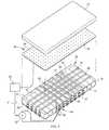
- FIG. 1is an exploded, schematic perspective view showing a mattress, a sensor array, a sensor cover, and a series of thermally conductive straps and associated heat flow augmentors.
- FIGS. 2-4are plan views of the mattress, sensor array and sensor cover of FIG. 1 .
- FIG. 5is an enlarged view of a portion of FIG. 4 showing the thermally conductive straps.
- FIG. 6is a plan view of the mattress showing the sensor array in relation to the thermally conductive straps and also showing a region of risk on the mattress.
- FIG. 7is a view similar to that of FIG. 1 showing two regions of risk.
- FIG. 8is a plan view of a mattress showing a diagonal arrangement of the thermally conductive straps.
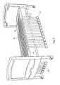
- FIG. 9is a perspective view of a bed showing an arrangement with elongated thermally conductive straps.
- FIG. 10is an elevation view of the bed of FIG. 9 as seen by an observer viewing the bed in the longitudinal direction.
- FIG. 11is a view substantially in the direction 11 - 11 of FIG. 10 .
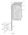
- FIG. 12is an elevation view showing an heat flow augmentor exemplified by a thermoelectric module and a fan for drawing ambient air past the module.
- FIG. 13is a schematic plan view of a portion of a mattress having thermally conductive lateral straps, a fan and a duct arrangement for directing ambient air through the ducts.
- FIG. 14is a view similar to that of FIG. 13 including a chiller for chilling the ambient air.
- FIG. 15is a schematic elevation view showing a multi-layer mattress.
- FIGS. 1-4show an occupant support comprising a mattress 20 having fluid filled bladders 22 enclosed in a bladder covering 24 .
- the mattresshas a head end border 26 , a foot end border 28 longitudinally spaced from the head end border, a left flank 32 and a right flank 34 laterally spaced from the left flank.
- the bladderstypically contain air but could also contain water or other liquid.
- An energy management systemincludes a series of thermally conductive lateral straps 38 extending laterally across the covering and vertically along the left and right flanks 32 , 34 and a series of thermally conductive longitudinal straps 40 extending longitudinally along the covering and vertically along the head and foot borders 26 , 28 .
- the lateral and longitudinal strapsmay contact each other at thermally conductive junctures 42 or may be thermally insulated from each other at the locations where they would otherwise intersect and form thermally conductive junctures.
- the term “juncture” and reference numeral 42are used herein to refer to both an actual, thermally conductive juncture and a nonconductive juxtaposition of the lateral and longitudinal straps.
- the strapsdefine thermally conductive pathways.
- the straps 38 , 40are made of a heat conducting material such as thermally conductive fibers having a thermal conductivity of at least about 4 Watts/meter/degree Kelvin.
- thermally conductive fibershaving a thermal conductivity of at least about 4 Watts/meter/degree Kelvin.
- fibersinclude pitch based carbon fibers and high conductivity polymers.
- the energy management systemalso includes one or more heat flow augmentors 46 such as thermoelectric module 48 .
- a thermoelectric moduleis a solid state device that converts electrical energy into a thermal gradient. Specifically, when a voltage source 52 applies a voltage to the leads of the thermoelectric module, one side of the thermoelectric module becomes cooler and is referred to as the cold side; the other side of the thermoelectric module becomes warmer and is referred to as the hot side.
- the cold side of a thermoelectric modulecontacts the left and right termini of each lateral strap and the head and foot termini of each longitudinal strap.
- the hot side of each thermoelectric modulecommunicates with a heat sink, which in FIG. 1 is the ambient air.
- thermoelectric moduleassociated with each strap
- an architecture in which only selected straps are outfitted with a thermoelectric modulecan be beneficial. To preserve the clarity of FIG. 1 only the connection between the voltage source and one of the thermoelectric modules is shown.
- the occupant supportalso includes a detector 54 such as pressure sensor array 56 comprising multiple, individual pressure sensors 58 and a controller 60 .
- a sensor cover 62covers the sensor array.
- the quantity of pressure sensorsmay be equal to or may differ from the number of strap junctures. It is not necessary for the pressure sensors to be vertically juxtaposed over the strap junctures.
- the controllercommunicates with the sensor array and issues a control command C.
- the detectore.g. the pressure sensor array
- the controllerreceives information (e.g. pressure data) from the sensor array to determine the location of the region or regions of risk. The determination may rely on the magnitude of the pressure, the rate of change of pressure (dP/dt), the time during which pressure exceeds a threshold or combinations of these and/or other factors.
- pressure derivativecould be used by adding air to a region at a known rate and monitoring the local pressure derivative.
- thermoelectric module 48 Fthe thermoelectric module closest to the identified juncture, by commanding the voltage source to apply a voltage across the terminals of module 48 F.
- module 48 Faugments the heat withdrawal through the portion of strap 38 B between the juncture 48 ′ and the module 48 F.
- Another possible algorithmactivates module 48 F and its lateral partner module 48 V.
- a third possible algorithmactivates all four modules 48 F, 48 V, 48 C, and 48 M in contact with the straps 40 C, 42 B that define the juncture.
- a fourth possible algorithmactivates all the thermoelectric modules within a specified horizontal distance D of the juncture, i.e. modules 48 E, 48 F, 48 G and 48 H.
- FIG. 6shows distance D as a radius that encompasses all the thermoelectric modules that, when projected onto the plane of the radius, fall within the radius. In other words distance D doesn't account for the vertical distance V ( FIG.
- thermoelectric module1
- Vthe distance between the modules.
- a fifth possible algorithmactivates a subset of modules whose operation will result in a desired amount of heat withdrawal. Note that “subset” can, in the limit, include all the modules.
- the desired amount of heat withdrawalmay or may not be as much as the maximum heat withdrawal capacity of the energy management system.
- the amount of heat transfer augmentation attributable to each thermoelectric modulecan be controlled by regulating the voltage applied across its terminals.
- FIG. 7shows multiple regions of risk 66 A, 66 B, each of which corresponds to multiple sensors.
- the control algorithmhas selected the strap junctures identified with a plus sign as the junctures corresponding to a region of risk, with the juncture at the juxtaposition of straps 40 B and 38 D corresponding to both regions 66 A and 66 B.
- the plus signs superimposed on thermoelectric modules 48 H, 48 I, 48 J, 48 R, 48 S, 48 T, 48 U and 48 Vsignify that the algorithm has activated those modules to transfer heat away from the two regions of risk.
- FIG. 8shows an alternate strap configuration in which the straps, designated 70 and 72 , extend diagonally rather than laterally and longitudinally.
- FIG. 9Another alternate configuration, shown in FIG. 9 , takes advantage of the fact that the high thermal conductivity straps will extract some amount of heat from the vicinity of the bed occupant even without operation of the heat extraction modules.
- the configuration of FIG. 9employs elongated straps that, unlike the straps of FIG. 1 , extend vertically below the mattress. The additional strap surface area exposed to the environment increases heat withdrawal whether or not the thermoelectric modules are activated.
- FIGS. 10 and 11show another strap arrangement in which lateral straps, rather than extending to the left and right flanks of the mattress, penetrate vertically through the mattress.
- the penetrating arrangementhas the advantage that the straps are not exposed at the lateral edges of the mattress where they could be more susceptible to damage or be an annoyance to the bed occupant and visitors or staff near the mattress edge.
- FIG. 12shows an enhancement in which a fan 74 dedicated to a thermoelectric module directs ambient air over the hot side of the thermoelectric module to further enhance heat transfer.
- FIG. 13shows an enhancement with a duct arrangement so that a single fan 74 ′ can direct ambient air over the hot side of two or more thermoelectric module to convectively augment the heat withdrawal.
- the duct arrangementincludes a trunk 78 and branches 80 . Valves 82 under the command of controller 60 admit air at least to the branches leading to activated thermoelectric modules. A common exhaust duct 84 is provided to collect the exhaust air from all the branches.
- FIG. 14shows an arrangement similar to that of FIG. 13 but which employs a chiller 86 to chill the air directed over the activated thermoelectric modules.
- the sensor arrayhas been described as an array of pressure sensors that rests on the mattress and under a sensor cover. Accordingly, the sensor array detects interface pressure, i.e. pressure at the occupant/cover or cover/sensor interface.
- the sensor arraycan reside between adjacent layers, e.g. layers L 2 and L 3 , and sense interface pressure at the corresponding inter-layer interface I 2-3 .
- the mattressis one having liquid filled bladders, the sensors could be installed in the interior of the bladders so that the sensors detect intra-bladder pressure rather than an interface pressure.
- pressure sensingis thought to be a useful way to determine regions of risk, sensing other parameters, such as temperature, and/or using alternative sensing technologies might also prove satisfactory for determining regions of risk.
- the mattress 20has been shown as a bladder type mattress, however the innovations described herein can also be used with other types of mattresses such as foam mattresses.
- thermoelectric modules 48are envisioned as suitable devices for promoting localized heat withdrawal, however a wide array of other types of heat exchange devices 46 can also be used.
Landscapes
- Health & Medical Sciences (AREA)
- Vascular Medicine (AREA)
- Thermal Sciences (AREA)
- Engineering & Computer Science (AREA)
- Biomedical Technology (AREA)
- Heart & Thoracic Surgery (AREA)
- Physics & Mathematics (AREA)
- Life Sciences & Earth Sciences (AREA)
- Animal Behavior & Ethology (AREA)
- General Health & Medical Sciences (AREA)
- Public Health (AREA)
- Veterinary Medicine (AREA)
- Mattresses And Other Support Structures For Chairs And Beds (AREA)
- Invalid Beds And Related Equipment (AREA)
Abstract
Description
Claims (19)
Priority Applications (2)
| Application Number | Priority Date | Filing Date | Title |
|---|---|---|---|
| US13/688,670US8578527B2 (en) | 2009-06-29 | 2012-11-29 | Localized microclimate management |
| US14/049,273US8800078B2 (en) | 2009-06-29 | 2013-10-09 | Localized microclimate management |
Applications Claiming Priority (2)
| Application Number | Priority Date | Filing Date | Title |
|---|---|---|---|
| US12/493,456US8327477B2 (en) | 2009-06-29 | 2009-06-29 | Localized microclimate management |
| US13/688,670US8578527B2 (en) | 2009-06-29 | 2012-11-29 | Localized microclimate management |
Related Parent Applications (1)
| Application Number | Title | Priority Date | Filing Date |
|---|---|---|---|
| US12/493,456ContinuationUS8327477B2 (en) | 2009-06-29 | 2009-06-29 | Localized microclimate management |
Related Child Applications (1)
| Application Number | Title | Priority Date | Filing Date |
|---|---|---|---|
| US14/049,273ContinuationUS8800078B2 (en) | 2009-06-29 | 2013-10-09 | Localized microclimate management |
Publications (2)
| Publication Number | Publication Date |
|---|---|
| US20130086745A1 US20130086745A1 (en) | 2013-04-11 |
| US8578527B2true US8578527B2 (en) | 2013-11-12 |
Family
ID=42711755
Family Applications (3)
| Application Number | Title | Priority Date | Filing Date |
|---|---|---|---|
| US12/493,456Active2031-03-07US8327477B2 (en) | 2009-06-29 | 2009-06-29 | Localized microclimate management |
| US13/688,670Expired - Fee RelatedUS8578527B2 (en) | 2009-06-29 | 2012-11-29 | Localized microclimate management |
| US14/049,273Expired - Fee RelatedUS8800078B2 (en) | 2009-06-29 | 2013-10-09 | Localized microclimate management |
Family Applications Before (1)
| Application Number | Title | Priority Date | Filing Date |
|---|---|---|---|
| US12/493,456Active2031-03-07US8327477B2 (en) | 2009-06-29 | 2009-06-29 | Localized microclimate management |
Family Applications After (1)
| Application Number | Title | Priority Date | Filing Date |
|---|---|---|---|
| US14/049,273Expired - Fee RelatedUS8800078B2 (en) | 2009-06-29 | 2013-10-09 | Localized microclimate management |
Country Status (3)
| Country | Link |
|---|---|
| US (3) | US8327477B2 (en) |
| EP (2) | EP2689756B1 (en) |
| JP (1) | JP5247763B2 (en) |
Cited By (11)
| Publication number | Priority date | Publication date | Assignee | Title |
|---|---|---|---|---|
| US20120172959A1 (en)* | 2011-01-05 | 2012-07-05 | Lachenbruch Charles A | Cooling System for an Occupant of an Occupant Support and a Cooling Garment |
| US20130205506A1 (en)* | 2012-02-14 | 2013-08-15 | Charles A. Lachenbruch | Topper with Preferential Fluid Flow Distribution |
| US8800078B2 (en) | 2009-06-29 | 2014-08-12 | Hill-Rom Services, Inc. | Localized microclimate management |
| US9333136B2 (en) | 2013-02-28 | 2016-05-10 | Hill-Rom Services, Inc. | Sensors in a mattress cover |
| US9463124B2 (en) | 2013-01-15 | 2016-10-11 | Hill-Rom Services, Inc. | Microclimate system for a patient support apparatus |
| US9572433B2 (en) | 2012-08-15 | 2017-02-21 | Hill-Rom Services, Inc. | Systems and methods for directing fluid flow in a mattress |
| US10765577B2 (en) | 2015-06-30 | 2020-09-08 | Hill-Rom Services, Inc. | Microclimate system for a patient support apparatus |
| US10827846B2 (en) | 2016-10-28 | 2020-11-10 | Sleep Number Corporation | Bed with foot warming system |
| US11311111B2 (en) | 2020-04-06 | 2022-04-26 | Purple Innovation, Llc | Ventilated mattresses |
| US11559421B2 (en) | 2015-06-25 | 2023-01-24 | Hill-Rom Services, Inc. | Protective dressing with reusable phase-change material cooling insert |
| US11583437B2 (en) | 2018-02-06 | 2023-02-21 | Aspen Surgical Products, Inc. | Reusable warming blanket with phase change material |
Families Citing this family (45)
| Publication number | Priority date | Publication date | Assignee | Title |
|---|---|---|---|---|
| EP2567637B1 (en) | 2006-10-13 | 2014-08-06 | Gentherm Incorporated | Air conditioning bed |
| US20150366367A1 (en) | 2007-03-19 | 2015-12-24 | Augustine Temperature Management LLC | Electric heating pad with electrosurgical grounding |
| US8283602B2 (en) | 2007-03-19 | 2012-10-09 | Augustine Temperature Management LLC | Heating blanket |
| US10201935B2 (en) | 2007-03-19 | 2019-02-12 | Augustine Temperature Management LLC | Electric heating pad |
| WO2009036077A1 (en) | 2007-09-10 | 2009-03-19 | Amerigon, Inc. | Operational control schemes for ventilated seat or bed assemblies |
| US8181290B2 (en) | 2008-07-18 | 2012-05-22 | Amerigon Incorporated | Climate controlled bed assembly |
| US9125497B2 (en) | 2007-10-15 | 2015-09-08 | Gentherm Incorporated | Climate controlled bed assembly with intermediate layer |
| US8893329B2 (en) | 2009-05-06 | 2014-11-25 | Gentherm Incorporated | Control schemes and features for climate-controlled beds |
| US8332975B2 (en) | 2009-08-31 | 2012-12-18 | Gentherm Incorporated | Climate-controlled topper member for medical beds |
| US8353069B1 (en)* | 2010-09-07 | 2013-01-15 | Miller Anthony W | Device for heating, cooling and emitting fragrance into bedding on a bed |
| US8969703B2 (en) | 2010-09-13 | 2015-03-03 | Tempronics, Inc. | Distributed thermoelectric string and insulating panel |
| US20120191164A1 (en)* | 2011-01-26 | 2012-07-26 | Gander Nicholas M | Radiant heating apparatus and method for therapeutic heating |
| WO2012125916A2 (en)* | 2011-03-16 | 2012-09-20 | Augustine Temperature Management, Llc | Heated under-body warming system |
| EP2713967B1 (en)* | 2011-05-23 | 2021-01-06 | Koninklijke Philips N.V. | Temperature-controlled multi-zone mattress-style support |
| US9101224B2 (en) | 2011-06-10 | 2015-08-11 | Picard Healthcare Technolgy (Dongguan) Co. Ltd. | Medical air mattress |
| US10143609B2 (en) | 2011-06-14 | 2018-12-04 | Picard Healthcare Technology (Dongguan) Co. Ltd. | Medical air mattress |
| US20140142462A1 (en)* | 2011-06-15 | 2014-05-22 | Koninklijke Philips N.V. | Peripheral temperature measuring |
| KR20140045408A (en) | 2011-07-06 | 2014-04-16 | 템프로닉스, 인크. | Integration of distributed thermoelectric heating and cooling |
| WO2013076628A1 (en)* | 2011-11-21 | 2013-05-30 | Koninklijke Philips Electronics N.V. | A system and a method for improving a person's sleep |
| US20130212808A1 (en)* | 2012-02-21 | 2013-08-22 | Charles A. Lachenbruch | Topper with Targeted Fluid Flow Distribution |
| CA2871060C (en)* | 2012-04-20 | 2022-10-04 | Life Support Technologies, Inc. | Methods and systems for monitoring a patient to reduce the incidence of pressure ulcers |
| US9638442B2 (en)* | 2012-08-07 | 2017-05-02 | Tempronics, Inc. | Medical, topper, pet wireless, and automated manufacturing of distributed thermoelectric heating and cooling |
| US9676310B2 (en) | 2012-09-25 | 2017-06-13 | Faurecia Automotive Seating, Llc | Vehicle seat with thermal device |
| US20150208815A1 (en)* | 2012-10-18 | 2015-07-30 | Tempur-Pedic Management, Llc | Support cushions including reticulated materials and methods for controlling surface temperature of same |
| US9326616B2 (en)* | 2013-01-10 | 2016-05-03 | Dreamwell, Ltd. | Active airflow temperature controlled bedding systems |
| US20140316495A1 (en) | 2013-04-17 | 2014-10-23 | Augustine Biomedical And Design, Llc | Conformable heated mattress |
| CN105848964B (en) | 2013-11-04 | 2020-01-03 | 坦普罗尼克斯公司 | Design of thermoelectric strings, plates and envelopes for function and durability |
| NZ722015A (en)* | 2014-01-13 | 2021-09-24 | Bedgear Llc | Ambient bed having a heat reclaim system |
| US9962122B2 (en) | 2014-04-10 | 2018-05-08 | Augustine Temperature Management LLC | Underbody warming systems |
| US20170202362A1 (en)* | 2014-04-10 | 2017-07-20 | Neven Sleep, Llc | Ventilating sleep system |
| US9711029B2 (en) | 2014-10-31 | 2017-07-18 | Hill-Rom Services, Inc. | Equipment, dressing and garment wireless connectivity to a patient bed |
| WO2016077742A1 (en) | 2014-11-13 | 2016-05-19 | Augustine Temperature Management, Llc | Heated underbody warming systems with electrosurgical grounding |
| US9913770B2 (en)* | 2015-02-17 | 2018-03-13 | Hill-Rom Services, Inc. | Climate management topper with shape change actuators for regulating coolant distribution |
| EP3167765B1 (en) | 2015-11-13 | 2023-08-23 | Hill-Rom Services, Inc. | Person support systems with cooling features |
| CN106263798B (en)* | 2016-08-30 | 2018-09-18 | 浙江和也健康科技有限公司 | A kind of intelligence magnetic mattress |
| CN106263799B (en)* | 2016-08-30 | 2018-10-09 | 浙江和也健康科技有限公司 | A kind of intelligence health-care mattress |
| CN106419284B (en)* | 2016-08-31 | 2019-03-08 | 深圳市路福寝具有限公司 | A kind of Intelligent temperature-control mattress and its control method |
| US10966889B2 (en) | 2016-12-29 | 2021-04-06 | Hill-Rom Services, Inc. | Support apparatuses comprising cooling elements |
| US10842288B2 (en) | 2017-01-31 | 2020-11-24 | Hill-Rom Services, Inc. | Person support systems with cooling features |
| EP3479808A1 (en)* | 2017-10-26 | 2019-05-08 | Hill-Rom Services, Inc. | Underbody warming system with focal cooling |
| WO2019226968A1 (en)* | 2018-05-25 | 2019-11-28 | Magna Seating Inc. | Vehicle seat with cooling and heating using a flexible thermoelectric device |
| LU100834B1 (en)* | 2018-06-12 | 2019-12-12 | Variowell Dev Gmbh | A padding having hollow volumes and a flexible band |
| US10765580B1 (en) | 2019-03-27 | 2020-09-08 | Augustine Biomedical And Design, Llc | Patient securement system for the surgical trendelenburg position |
| WO2022231953A1 (en)* | 2021-04-29 | 2022-11-03 | Holtquist Zachariah Clarence | Mattress |
| US11844733B1 (en) | 2022-06-23 | 2023-12-19 | Augustine Biomedical And Design, Llc | Patient securement system for the surgical Trendelenburg position |
Citations (13)
| Publication number | Priority date | Publication date | Assignee | Title |
|---|---|---|---|---|
| US3738702A (en) | 1972-03-15 | 1973-06-12 | Gen Motors Corp | Means for cooling and heating a seat structure |
| US3888259A (en) | 1973-08-21 | 1975-06-10 | Robert C Miley | Hypothermia system |
| US5800480A (en) | 1996-08-30 | 1998-09-01 | Augustine Medical, Inc. | Support apparatus with a plurality of thermal zones providing localized cooling |
| EP0862901A1 (en) | 1997-03-05 | 1998-09-09 | Ohmeda Inc. | Thermoelectric infant mattress |
| US6772825B2 (en)* | 2002-11-04 | 2004-08-10 | Charles A. Lachenbruch | Heat exchange support surface |
| US20050288749A1 (en) | 2004-06-08 | 2005-12-29 | Lachenbruch Charles A | Heat wick for skin cooling |
| WO2006023479A2 (en) | 2004-08-16 | 2006-03-02 | Hill-Rom Services, Inc. | Dynamic cellular person support surface |
| US20060162074A1 (en)* | 2003-02-04 | 2006-07-27 | Gaby Bader | Device and method for controlling physical properties of a bed |
| WO2007016054A2 (en) | 2005-07-26 | 2007-02-08 | Hill-Rom Services, Inc. | System and method of controlling an air mattress |
| EP1779824A2 (en) | 2001-09-11 | 2007-05-02 | Hill-Rom Services, Inc. | Thermo-regulating patient support structure |
| US20070135878A1 (en) | 2003-06-13 | 2007-06-14 | Lachenbruch Charles A | Self-powered steady-state skin-cooling support surfaces |
| US20070272673A1 (en)* | 2001-08-29 | 2007-11-29 | Keane Barry P | Electric mattress and mattress pad |
| US20100325796A1 (en) | 2009-06-29 | 2010-12-30 | Lachenbruch Charles A | Localized Microclimate Management |
- 2009
- 2009-06-29USUS12/493,456patent/US8327477B2/enactiveActive
- 2010
- 2010-06-11JPJP2010133903Apatent/JP5247763B2/ennot_activeExpired - Fee Related
- 2010-06-17EPEP13190107.6Apatent/EP2689756B1/ennot_activeNot-in-force
- 2010-06-17EPEP10251104Apatent/EP2269547A1/ennot_activeWithdrawn
- 2012
- 2012-11-29USUS13/688,670patent/US8578527B2/ennot_activeExpired - Fee Related
- 2013
- 2013-10-09USUS14/049,273patent/US8800078B2/ennot_activeExpired - Fee Related
Patent Citations (18)
| Publication number | Priority date | Publication date | Assignee | Title |
|---|---|---|---|---|
| US3738702A (en) | 1972-03-15 | 1973-06-12 | Gen Motors Corp | Means for cooling and heating a seat structure |
| US3888259A (en) | 1973-08-21 | 1975-06-10 | Robert C Miley | Hypothermia system |
| US5800480A (en) | 1996-08-30 | 1998-09-01 | Augustine Medical, Inc. | Support apparatus with a plurality of thermal zones providing localized cooling |
| US6033432A (en) | 1996-08-30 | 2000-03-07 | Augustine Medical, Inc. | Support apparatus with a plurality of thermal zones providing localized cooling |
| EP0862901A1 (en) | 1997-03-05 | 1998-09-09 | Ohmeda Inc. | Thermoelectric infant mattress |
| US20070272673A1 (en)* | 2001-08-29 | 2007-11-29 | Keane Barry P | Electric mattress and mattress pad |
| EP1779824A2 (en) | 2001-09-11 | 2007-05-02 | Hill-Rom Services, Inc. | Thermo-regulating patient support structure |
| US6772825B2 (en)* | 2002-11-04 | 2004-08-10 | Charles A. Lachenbruch | Heat exchange support surface |
| US20060162074A1 (en)* | 2003-02-04 | 2006-07-27 | Gaby Bader | Device and method for controlling physical properties of a bed |
| US20070135878A1 (en) | 2003-06-13 | 2007-06-14 | Lachenbruch Charles A | Self-powered steady-state skin-cooling support surfaces |
| US7727267B2 (en)* | 2003-06-13 | 2010-06-01 | Charles Arthur Lachenbruch | Self-powered steady-state skin-cooling support surfaces |
| US7273490B2 (en) | 2004-06-08 | 2007-09-25 | Charles Arthur Lachenbruch | Heat wick for skin cooling |
| US20050288749A1 (en) | 2004-06-08 | 2005-12-29 | Lachenbruch Charles A | Heat wick for skin cooling |
| US20060085919A1 (en) | 2004-08-16 | 2006-04-27 | Kramer Kenneth L | Dynamic cellular person support surface |
| WO2006023479A2 (en) | 2004-08-16 | 2006-03-02 | Hill-Rom Services, Inc. | Dynamic cellular person support surface |
| WO2007016054A2 (en) | 2005-07-26 | 2007-02-08 | Hill-Rom Services, Inc. | System and method of controlling an air mattress |
| US20100325796A1 (en) | 2009-06-29 | 2010-12-30 | Lachenbruch Charles A | Localized Microclimate Management |
| US8327477B2 (en) | 2009-06-29 | 2012-12-11 | Hill-Rom Services, Inc. | Localized microclimate management |
Non-Patent Citations (3)
| Title |
|---|
| European Search Report, "Application No. EP 10251104", (Sep. 27, 2010), The Hague. |
| Paul A. Iaizzo, PhD, Craig L. Kveen, BS, Jaydeep Y. Kokate, MS, Keith J. Leland BS, Gary L. Hansen, MS, Ephraim M. Sparrow, PhD, Prevention of Pressure Ulcers by Focal Cooling: Histological Assessment in a Porcine Model, Wounds 1995; 7 (5): 161-169, Sep./Oct. 1995, Paul A. Izizzo, PhD, Department of Anesthesiology. |
| Paul A. Iaizzo, PhD, Temperature Modulation of Pressure Ulcer Formation: Using a Swine Model, From the Departments of Surgery and Physiology, University of Minnesota, Minneapolis, Minnesota, Wounds 2004; 16 (11): 336-343, Paul A. Iaizzo, PhD, Experimental Surgical Services, Department of Surgery, MMC 107, University of Minnesota 420 Delaware St. S.E., Minneapolis, MN 55455 612-624-7912; Fax 612-624-2002, E-mail: iaizz001@umn.edu. |
Cited By (18)
| Publication number | Priority date | Publication date | Assignee | Title |
|---|---|---|---|---|
| US8800078B2 (en) | 2009-06-29 | 2014-08-12 | Hill-Rom Services, Inc. | Localized microclimate management |
| US20120172959A1 (en)* | 2011-01-05 | 2012-07-05 | Lachenbruch Charles A | Cooling System for an Occupant of an Occupant Support and a Cooling Garment |
| US10010446B2 (en)* | 2011-01-05 | 2018-07-03 | Hill-Rom Services, Inc. | Cooling system for an occupant of an occupant support and a cooling garment |
| US20130205506A1 (en)* | 2012-02-14 | 2013-08-15 | Charles A. Lachenbruch | Topper with Preferential Fluid Flow Distribution |
| US9131780B2 (en)* | 2012-02-14 | 2015-09-15 | Hill-Rom Services, Inc. | Topper with preferential fluid flow distribution |
| US9943172B2 (en) | 2012-02-14 | 2018-04-17 | Hill-Rom Services, Inc. | Mattress topper with varying flow resistance |
| US10555854B2 (en) | 2012-08-15 | 2020-02-11 | Hill-Rom Services, Inc. | Systems and methods for directing fluid flow in a mattress |
| US9572433B2 (en) | 2012-08-15 | 2017-02-21 | Hill-Rom Services, Inc. | Systems and methods for directing fluid flow in a mattress |
| US9463124B2 (en) | 2013-01-15 | 2016-10-11 | Hill-Rom Services, Inc. | Microclimate system for a patient support apparatus |
| US9730847B2 (en) | 2013-01-15 | 2017-08-15 | Hill-Rom Services, Inc. | Microclimate system for a patient support apparatus |
| US9333136B2 (en) | 2013-02-28 | 2016-05-10 | Hill-Rom Services, Inc. | Sensors in a mattress cover |
| US11684529B2 (en) | 2013-02-28 | 2023-06-27 | Hill-Rom Services, Inc. | Mattress cover sensor method |
| US11559421B2 (en) | 2015-06-25 | 2023-01-24 | Hill-Rom Services, Inc. | Protective dressing with reusable phase-change material cooling insert |
| US10765577B2 (en) | 2015-06-30 | 2020-09-08 | Hill-Rom Services, Inc. | Microclimate system for a patient support apparatus |
| US10827846B2 (en) | 2016-10-28 | 2020-11-10 | Sleep Number Corporation | Bed with foot warming system |
| US11844433B2 (en) | 2016-10-28 | 2023-12-19 | Sleep Number Corporation | Bed with foot warming system |
| US11583437B2 (en) | 2018-02-06 | 2023-02-21 | Aspen Surgical Products, Inc. | Reusable warming blanket with phase change material |
| US11311111B2 (en) | 2020-04-06 | 2022-04-26 | Purple Innovation, Llc | Ventilated mattresses |
Also Published As
| Publication number | Publication date |
|---|---|
| JP5247763B2 (en) | 2013-07-24 |
| US20130086745A1 (en) | 2013-04-11 |
| US8800078B2 (en) | 2014-08-12 |
| US8327477B2 (en) | 2012-12-11 |
| EP2269547A1 (en) | 2011-01-05 |
| US20100325796A1 (en) | 2010-12-30 |
| JP2011005249A (en) | 2011-01-13 |
| US20140041118A1 (en) | 2014-02-13 |
| EP2689756B1 (en) | 2015-04-01 |
| EP2689756A1 (en) | 2014-01-29 |
Similar Documents
| Publication | Publication Date | Title |
|---|---|---|
| US8578527B2 (en) | Localized microclimate management | |
| US20220128276A1 (en) | Integration of distributed thermoelectric heating and cooling | |
| US9119479B2 (en) | Adjustable-firmness body support and method | |
| US9463124B2 (en) | Microclimate system for a patient support apparatus | |
| US10667622B1 (en) | Multi-zone temperature modulation system for bed or blanket | |
| EP0862901A1 (en) | Thermoelectric infant mattress | |
| US20120165908A1 (en) | Cold/hot therapy device with temperature control | |
| MXPA97006560A (en) | Support device with a plurality of thermal zones that provide local cooling | |
| EP3167765B1 (en) | Person support systems with cooling features | |
| KR20060124553A (en) | Temperature control mat | |
| KR102350537B1 (en) | A Temperature Regulating Mat for a Pet | |
| EP3116349B1 (en) | Pressure variable thermal adaptive microclimate surface and thermoelectric cells for microclimate surface | |
| CN102802567A (en) | Temperature control apparatus and method for thermoregulation of a human body | |
| US6646232B2 (en) | Fail safe device for infant-support apparatus | |
| KR102107433B1 (en) | Thermostatic pillows and method using peltier module | |
| EP3262989A1 (en) | Airflow control for head support | |
| US20190125578A1 (en) | Underbody warming system with focal cooling | |
| NL1010728C2 (en) | Fluid filled mattress. | |
| KR200320965Y1 (en) | Heating stone bed using circulating heated water separately | |
| KR20200098966A (en) | A Temperature Regulating Mat for a Pet | |
| JPH06304047A (en) | Water bed with cooler | |
| KR20200132088A (en) | Cool or hot water combination type mat | |
| ITMI961089A1 (en) | DEVICE FOR THE THERMAL CONDITIONING OF OBJECTS SUBJECT TO BE CONTACTED BY THE HUMAN BODY, ESPECIALLY FOR BEDS OR | |
| ITMI970464U1 (en) | DEVICE FOR THE THERMAL CONDITIONING OF OBJECTS LIKELY TO BE CONTACTED BY THE HUMAN BODY ESPECIALLY FOR BEDS OR SIMILAR |
Legal Events
| Date | Code | Title | Description |
|---|---|---|---|
| AS | Assignment | Owner name:JPMORGAN CHASE BANK, N.A., AS COLLATERAL AGENT, ILLINOIS Free format text:SECURITY INTEREST;ASSIGNORS:ALLEN MEDICAL SYSTEMS, INC.;HILL-ROM SERVICES, INC.;ASPEN SURGICAL PRODUCTS, INC.;AND OTHERS;REEL/FRAME:036582/0123 Effective date:20150908 Owner name:JPMORGAN CHASE BANK, N.A., AS COLLATERAL AGENT, IL Free format text:SECURITY INTEREST;ASSIGNORS:ALLEN MEDICAL SYSTEMS, INC.;HILL-ROM SERVICES, INC.;ASPEN SURGICAL PRODUCTS, INC.;AND OTHERS;REEL/FRAME:036582/0123 Effective date:20150908 | |
| AS | Assignment | Owner name:JPMORGAN CHASE BANK, N.A., AS COLLATERAL AGENT, ILLINOIS Free format text:SECURITY AGREEMENT;ASSIGNORS:HILL-ROM SERVICES, INC.;ASPEN SURGICAL PRODUCTS, INC.;ALLEN MEDICAL SYSTEMS, INC.;AND OTHERS;REEL/FRAME:040145/0445 Effective date:20160921 Owner name:JPMORGAN CHASE BANK, N.A., AS COLLATERAL AGENT, IL Free format text:SECURITY AGREEMENT;ASSIGNORS:HILL-ROM SERVICES, INC.;ASPEN SURGICAL PRODUCTS, INC.;ALLEN MEDICAL SYSTEMS, INC.;AND OTHERS;REEL/FRAME:040145/0445 Effective date:20160921 | |
| REMI | Maintenance fee reminder mailed | ||
| LAPS | Lapse for failure to pay maintenance fees | Free format text:PATENT EXPIRED FOR FAILURE TO PAY MAINTENANCE FEES (ORIGINAL EVENT CODE: EXP.) | |
| STCH | Information on status: patent discontinuation | Free format text:PATENT EXPIRED DUE TO NONPAYMENT OF MAINTENANCE FEES UNDER 37 CFR 1.362 | |
| FP | Lapsed due to failure to pay maintenance fee | Effective date:20171112 | |
| AS | Assignment | Owner name:HILL-ROM SERVICES, INC., ILLINOIS Free format text:RELEASE BY SECURED PARTY;ASSIGNOR:JPMORGAN CHASE BANK, N.A.;REEL/FRAME:050254/0513 Effective date:20190830 Owner name:ALLEN MEDICAL SYSTEMS, INC., ILLINOIS Free format text:RELEASE BY SECURED PARTY;ASSIGNOR:JPMORGAN CHASE BANK, N.A.;REEL/FRAME:050254/0513 Effective date:20190830 Owner name:MORTARA INSTRUMENT SERVICES, INC., WISCONSIN Free format text:RELEASE BY SECURED PARTY;ASSIGNOR:JPMORGAN CHASE BANK, N.A.;REEL/FRAME:050254/0513 Effective date:20190830 Owner name:MORTARA INSTRUMENT, INC., WISCONSIN Free format text:RELEASE BY SECURED PARTY;ASSIGNOR:JPMORGAN CHASE BANK, N.A.;REEL/FRAME:050254/0513 Effective date:20190830 Owner name:HILL-ROM COMPANY, INC., ILLINOIS Free format text:RELEASE BY SECURED PARTY;ASSIGNOR:JPMORGAN CHASE BANK, N.A.;REEL/FRAME:050254/0513 Effective date:20190830 Owner name:HILL-ROM, INC., ILLINOIS Free format text:RELEASE BY SECURED PARTY;ASSIGNOR:JPMORGAN CHASE BANK, N.A.;REEL/FRAME:050254/0513 Effective date:20190830 Owner name:ANODYNE MEDICAL DEVICE, INC., FLORIDA Free format text:RELEASE BY SECURED PARTY;ASSIGNOR:JPMORGAN CHASE BANK, N.A.;REEL/FRAME:050254/0513 Effective date:20190830 Owner name:WELCH ALLYN, INC., NEW YORK Free format text:RELEASE BY SECURED PARTY;ASSIGNOR:JPMORGAN CHASE BANK, N.A.;REEL/FRAME:050254/0513 Effective date:20190830 Owner name:VOALTE, INC., FLORIDA Free format text:RELEASE BY SECURED PARTY;ASSIGNOR:JPMORGAN CHASE BANK, N.A.;REEL/FRAME:050254/0513 Effective date:20190830 |