US8577437B2 - System for in-vivo measurement of an analyte concentration - Google Patents
System for in-vivo measurement of an analyte concentrationDownload PDFInfo
- Publication number
- US8577437B2 US8577437B2US12/052,313US5231308AUS8577437B2US 8577437 B2US8577437 B2US 8577437B2US 5231308 AUS5231308 AUS 5231308AUS 8577437 B2US8577437 B2US 8577437B2
- Authority
- US
- United States
- Prior art keywords
- sensor
- housing
- base station
- chamber
- data carrier
- Prior art date
- Legal status (The legal status is an assumption and is not a legal conclusion. Google has not performed a legal analysis and makes no representation as to the accuracy of the status listed.)
- Active, expires
Links
- 239000012491analyteSubstances0.000titleclaimsabstractdescription21
- 238000012623in vivo measurementMethods0.000titleclaimsdescription22
- 241001465754MetazoaSpecies0.000claimsabstractdescription12
- 238000011156evaluationMethods0.000claimsabstractdescription9
- 238000001727in vivoMethods0.000claimsabstractdescription5
- 238000005259measurementMethods0.000claimsabstract3
- 238000004806packaging method and processMethods0.000claimsdescription32
- 238000000034methodMethods0.000claimsdescription12
- 230000001954sterilising effectEffects0.000claimsdescription7
- 238000004659sterilization and disinfectionMethods0.000claimsdescription6
- 239000000126substanceSubstances0.000claimsdescription6
- 230000008878couplingEffects0.000claimsdescription5
- 238000010168coupling processMethods0.000claimsdescription5
- 238000005859coupling reactionMethods0.000claimsdescription5
- 238000007789sealingMethods0.000claimsdescription5
- 210000001124body fluidAnatomy0.000abstractdescription3
- WQZGKKKJIJFFOK-GASJEMHNSA-NGlucoseNatural productsOC[C@H]1OC(O)[C@H](O)[C@@H](O)[C@@H]1OWQZGKKKJIJFFOK-GASJEMHNSA-N0.000abstract1
- 239000010839body fluidSubstances0.000abstract1
- 239000008103glucoseSubstances0.000abstract1
- 238000003780insertionMethods0.000description8
- 230000037431insertionEffects0.000description8
- 238000004519manufacturing processMethods0.000description6
- 239000000969carrierSubstances0.000description5
- 239000004033plasticSubstances0.000description3
- 230000005855radiationEffects0.000description3
- 230000035945sensitivityEffects0.000description3
- 210000001015abdomenAnatomy0.000description2
- 230000001771impaired effectEffects0.000description2
- 230000009286beneficial effectEffects0.000description1
- 239000008280bloodSubstances0.000description1
- 210000004369bloodAnatomy0.000description1
- 230000000694effectsEffects0.000description1
- 210000003722extracellular fluidAnatomy0.000description1
- 239000002184metalSubstances0.000description1
- 230000005405multipoleEffects0.000description1
- 238000012856packingMethods0.000description1
- 239000002985plastic filmSubstances0.000description1
- 238000012360testing methodMethods0.000description1
- 238000012546transferMethods0.000description1
Images

Classifications
- A—HUMAN NECESSITIES
- A61—MEDICAL OR VETERINARY SCIENCE; HYGIENE
- A61B—DIAGNOSIS; SURGERY; IDENTIFICATION
- A61B5/00—Measuring for diagnostic purposes; Identification of persons
- A61B5/145—Measuring characteristics of blood in vivo, e.g. gas concentration or pH-value ; Measuring characteristics of body fluids or tissues, e.g. interstitial fluid or cerebral tissue
- A61B5/1495—Calibrating or testing of in-vivo probes
- A—HUMAN NECESSITIES
- A61—MEDICAL OR VETERINARY SCIENCE; HYGIENE
- A61B—DIAGNOSIS; SURGERY; IDENTIFICATION
- A61B2560/00—Constructional details of operational features of apparatus; Accessories for medical measuring apparatus
- A61B2560/02—Operational features
- A61B2560/0223—Operational features of calibration, e.g. protocols for calibrating sensors
- A—HUMAN NECESSITIES
- A61—MEDICAL OR VETERINARY SCIENCE; HYGIENE
- A61B—DIAGNOSIS; SURGERY; IDENTIFICATION
- A61B2562/00—Details of sensors; Constructional details of sensor housings or probes; Accessories for sensors
- A61B2562/24—Hygienic packaging for medical sensors; Maintaining apparatus for sensor hygiene
- A61B2562/242—Packaging, i.e. for packaging the sensor or apparatus before use
- A—HUMAN NECESSITIES
- A61—MEDICAL OR VETERINARY SCIENCE; HYGIENE
- A61B—DIAGNOSIS; SURGERY; IDENTIFICATION
- A61B5/00—Measuring for diagnostic purposes; Identification of persons
- A61B5/15—Devices for taking samples of blood
- A61B5/150007—Details
- A61B5/150015—Source of blood
- A61B5/150022—Source of blood for capillary blood or interstitial fluid
Definitions
- the disclosurerelates to a system for the in-vivo measurement of an analyte concentration in a human or animal body.
- sensors for the measuring of analyte concentrations of bodily fluidssuch as, e.g., blood or interstitial fluids cannot be manufactured with exactly preset measuring sensitivities. Typically, considerable deviations occur between production batches.
- calibration dataare therefore required that were either determined at the pertinent sensor itself or by means of random testing of other sensors of the pertinent production batch. In general, such calibration data describe the difference between an ideal sensor sensitivity and a determined sensor sensitivity.
- Systems for the in-vivo measurement of analyte concentrationstypically comprise exchangeable sensors as exchange or consumable components and a long-life base station to which the exchangeable sensors are connected. This brings about the problem that at each exchange of sensor, new calibration data must be made available to the system.
- Calibration datacan be made available on a packing leaflet for the sensor and be manually entered by the user into the system. Because this procedure entails, however, the danger of input errors it is more beneficial to accompany each sensor or each sensor package with a data carrier with thereto stored calibration data in order to preclude the risk of input errors.
- the sensors of an in-vivo measuring systemmust be sterile because they are inserted into the body of a patient.
- the customary method of sterilizationto wit, an intensive irradiation, entails considerable difficulties.
- electronic or magnetic data carriersare impaired due to the required radiation dose required for sterilization, it is not possible, or only with very expensive, especially manufactured data carriers, to irradiate the sealed housing with the therein arranged sensor and data carrier to sterilize the sensor.
- the in-vivo measurement of an analyte concentration in a human or animal bodycomprising exchangeable sensors for generating measuring signals that correlate to the analyte concentration to be measured, data carriers with calibration data of the sensors, a base station to which at least one of the exchangeable sensors and a therewith associated data carrier with calibration data can be connected so that, during operation, measuring signals generated by a connected sensor can be transmitted to an evaluation unit that evaluates the measuring signals generated by the connected sensor by means of the calibration data that were read from the data carrier associated with the connected sensor.
- the inventionrelates further to a packaging system for exchange components of such a measuring system and a method for packaging of a sensor and a data carrier in which the sensor's calibration data are stored.
- An embodiment of the housingis provided with at least two separate chambers wherein in a first chamber at least one of the sensors is arranged in sterile conditions and in the second chamber a data carrier with the calibration data of the sensor, wherein the housing is adapted to an interface of the base station so that the sensor in the housing and the therewith associated data carrier are connectable to the base station by setting the housing to the interface.
- the sensor and the data carriercan be connected to the base station in a single operational step, insofar as the housing in which they are arranged is set to the base interface of the base station adapted to the housing. In such a manner, the risk of transposing data carriers or an erroneous connection of sensors can be effectively met.
- the housingwherein are arranged at least one sensor and a therewith associated data carrier, can be a packaging housing which is intended to be either totally or partially removed anew from the base station prior to effectuating an in-vivo measurement.
- the housingcontinues to be connected to the base station.
- the housinghas at least two separate chambers.
- the sensoris, at first, arranged in the first housing chamber, the housing is subsequently sealed and the sensor in the first housing chamber is sterilized by irradiation effect. After the completion of the sterilization process, the data carrier is arranged in the second housing chamber which is then closed.
- This method for the packaging of a sensor and a therewith associated data carrieris also an aspect of the invention.
- a further aspect of the disclosurerelates to a packaging system for exchange components of an in-vivo measuring system, according to the invention; the packaging system comprising a housing with at least two separate chambers, at least one sensor for generating measuring signals, that correlate to the analyte concentration to be measured, and a data carrier with calibration data of at least the one sensor, wherein the sensor is arranged under sterile conditions in a first chamber of the housing and the data carrier with the calibration data of the sensor is arranged in a second chamber of the housing.
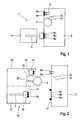
- FIG. 1shows a schematic representation embodiment of a base station and a thereto connected sensor of a system for the in-vivo measurement of an analyte concentration in a human or animal body;
- FIG. 2shows the base station of the embodiment illustrated in FIG. 1 and an embodiment of a packaging system with exchange components to be connected to the base station;
- FIG. 3shows a packaging system embodiment specified for the connection of the exchange components to the base station
- FIG. 4shows an operational step for the manufacture of the packaging system illustrated in FIG. 2 ;
- FIG. 5shows another operational step for the manufacture of the packaging system
- FIG. 6shows the packaging system with an outer packaging
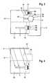
- FIG. 7shows another embodiment of a system, according to the invention, for the in-vivo measurement of an analyte concentration in a human or animal body
- FIG. 8shows a cross-sectional illustration of FIG. 7 .
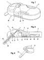
- FIG. 9shows a sensor housing of the embodiment illustrated in FIGS. 7 and 8 .
- FIG. 1shows a schematic illustration of a base station 2 of a system 1 for the in-vivo measurement of an analyte concentration in a human or animal body with a sensor 3 connected to the base station 2 for generating measuring signals that correlate to the analyte concentration to be measured.
- FIG. 1shows a human or animal body, symbolically represented by the box 4 , into which is inserted the sensor 3 for an in-vivo measurement.
- the system 1comprises a battery 5 connected to the base station 2 as another consumable or exchange component.
- the base station 2is intended to be attached to the body of the patient during the in-vivo measurement and comprises a potentiostat that supplies the connected electro-chemical sensor 3 with electric current and holds a preset value of an electric potential at a measuring electrode of the sensor 3 with respect to the reference electrode of the sensor 3 .
- the base station 2also comprises an electronic evaluation unit which, during operation, evaluates by means of calibration data the measuring signals generated by a connected sensor 3 .
- the evaluation unitin a device separate from the base station, to which device the measuring signals are made available by, e.g., radio or a data transfer line.
- FIG. 1shows connection contacts 6 a , 6 b , 6 c of the base station 2 for connecting of the sensor 3 , and connection contacts 7 a , 7 b of the base station 2 for connecting of the battery 5 .
- the base station 2has also at least one data input 8 a , 8 b for the connecting and the readout of a data carrier with calibration data, which can be removed from the base station 2 after the readout of the calibration data and which, therefore, is not shown in the operating state illustrated in FIG. 1 .
- the data input 8 a , 8 bis coupled with spring elements 9 which, through elastic force, facilitate the attaching of a data carrier.
- the data carrieris preferably a storage chip so that the data input is formed by electric connection contacts.
- the data carriercan also be a magnetic data carrier and the data input 8 a , 8 b can correspondingly comprise a reader head.
- FIG. 2is a schematic illustration of the shown base station without connected exchange components. Additionally, FIG. 2 shows schematically a packaging system 10 for the exchange components (in particular, sensor 3 , battery 5 and data carrier 11 with calibration data) which, together with the base station 2 , constitute a system 1 for the in-vivo measurement of an analyte concentration in a human or animal body.
- the packaging system 10comprises a housing 12 with at least two separate chambers 13 , 14 , 15 , wherein in the first chamber 13 is arranged under sterile conditions the sensor 3 and in a second chamber the data carrier 11 with calibration data of the sensor 3 .
- the battery 5is arranged in a third chamber 15 .
- the housing 12is fastened to an interface of the base station 2 in such manner that the sensor 3 , arranged in the housing 12 and the therewith associated data carrier 11 , can be connected to the base station by setting the housing 12 to the interface.
- FIG. 3illustrates schematically the setting of the housing 12 to the interface of the base station 2 for the connecting of the exchange components 3 , 5 , 11 .
- the measuring system 1is automatically initialized by connecting the exchange components 3 , 5 , 11 and the measuring process is initiated.
- the housing 12For connecting the exchange components 3 , 5 , 11 arranged in the housing 12 , the housing 12 , in particular the sterile housing chamber 13 , is opened.
- the housing 12 of the illustrated embodimentis provided with a rupture joint 16 so that a user can easily break off a housing part 17 , which seals the chambers 13 , 14 , 15 , from the housing 12 .
- This breakable housing part 17can be configured, e.g., as a cap.
- the housing part 17seals both the sterile chamber 13 in which is housed the sensor 3 as well as the chambers 14 , 15 wherein are arranged the data carrier 11 and the battery 5 .
- the housing 12is provided with a spring element 20 that facilitates the connecting of the battery 5 when the housing 12 is set to the interface of the base station 2 .
- spring elementscan also be arranged in the first chamber 13 and in the second chamber 14 to facilitate connecting of the sensor 3 and/or the data carrier 11 to the base station.
- the housing 12 and the interface of the base station 2are adapted to each other in such a manner that, when the housing 12 is set to the interface, the battery 5 and the data carrier 11 are connected to the base station first and it is only afterwards that the sensor 3 is connected to the base station 2 by means of the thereto provided contacts 6 a , 6 b and 6 c .
- the sensor 3has a flat structure and is connected to the base station 2 by means of a zero force plug 3 a .
- the sensor 3can also have, e.g., a sandwich structure or be configured rotationally symmetrical with the contacts 6 a , 6 b and 6 c being adapted thereto.
- a seal 21 of the base station 2which in the illustrated embodiment is configured as a sealing ring, provides for a watertight coupling of the sensor 3 to the base station 2 , so that no moisture can infiltrate into the inside of the base station 2 .
- the base station 2can be placed on the abdomen of a patient without risk of being damaged by bodily fluids.
- the seal 21effectuates a highly resistive sealing of the base station 2 and of the thereto connected sensor 3 .
- the sensor 3can be supplied with power as being an electro-chemical sensor by means of a potentiostat without being impaired by leakage currents.
- the housing 12is configured as a blister packaging. Compartments are formed in the plastic portion of the blister packaging that form the bottom and the walls of the chambers 13 , 14 , 15 of the housing 12 .
- a sensor 3is arranged in the first housing chamber 13 whereupon the chamber 13 is sealed. Subsequently, the sensor 3 in the housing chamber 13 will be sterilized by irradiation.
- electron rays ewith a dose of at last 20 kGy. In particular, especially appropriate is an electron ray dose of 28 kGy.
- the data carrier 11is described with calibration data 30 of the sensor 3 arranged in the first housing chamber 13 .
- These calibration data 30are determined by means of random checks of the same production batch after conclusion of the sterilization process.
- the data carrier 11is arranged in the second housing chamber 14 and the battery 5 in the housing chamber 15 .
- the housing chamber 14is sealed.
- the housing chambers 13 , 14 , 15can be sealed in the customary manner in the blister packaging, e.g., by means of a plastic or metal sheeting.
- the completed packaging system 10is packed in an outer packaging, in which it is sold, e.g., welded into a plastic sheet.
- FIG. 6illustrates such a packaging system 10 with an outer packaging 31 .
- the housing 12containing the exchange components
- the housing 12is a packaging housing which is intended to be removed from the base station 2 prior to the carrying out of an in-vivo measurement.
- FIGS. 7 to 9by means of FIGS. 7 to 9 is explained another embodiment, wherein the housing 12 , containing the exchange components, is fixed to the base station 2 during the carrying out of the in-vivo measurement.
- FIG. 7shows in a diagonal view the base station 2 with thereto attached housing 12 that contains the exchange components of system 1 .
- FIG. 8shows a cross-sectional view of FIG. 7 with the sterile housing chamber 13 with the therein arranged sensor 3 as well as the second housing chamber 14 with therein arranged battery 5 and data carrier 11 wherein are stored the calibration data of the sensor 3 .
- the base station 2is provided with a potentiostat 48 for the current and power supply of sensor 3 and an evaluation unit 47 , configured as a microprocessor which, during operation, evaluates the measuring signals generated by the connected sensor 3 by means of the calibration data that were read from the data carrier 11 associated with the sensor 3 .
- the potentiostat 48can also be configured as a consumable component and arranged together with the sensor 3 in the housing 12 , so that regarding high electrical resistance lower requirements can be placed on the sealing of the base.
- the evaluation unit 47can be arranged in a device separate from the base station 2 , which device can receive the data from the base station 2 .
- the housing 10 of the packaging system for consumable componentsis manufactured out of rigid plastic, alike to that of the base station 2 .
- the interface of the base station 2 and the housing 12 containing the consumable componentsare configured for an interlocking connection.
- the housing 12is provided with drop-in lugs 40 that engage in thereto adapted recesses of the interface of the base station 2 .
- These recessesare provided on the outsides of two spring legs 41 so that, by elastic force, the drop-in lugs are pressed into the recesses.
- the spring legs 41can be compressed, so that the drop-in lugs 40 of the housing 12 , containing the consumable components, are released from the thereto adapted recesses and the housing 12 can be removed from the base station 2 .
- the housing 12containing the consumable components, can be fastened to the base station 2 .
- the housing containing the consumable componentscan be also configured in such a manner that, for the connecting of the sensor arranged in the housing, it can be fastened to the base station 2 by means of clamping.
- FIG. 8shows that the housing 12 is provided with two separate chambers 13 , 14 , wherein in a first chamber 13 the sensor 3 is arranged under sterile conditions and that, in the second chamber 14 are arranged a data carrier 11 with the calibration data of the sensor 3 and a battery 5 for the power supply of the base station 2 .
- Connecting leads of the sensor 3extend from the first chamber 13 into the second chamber 14 to a circuit board 45 that is connected to the data carrier 11 configured as a storage chip.
- the circuit board 45is connected to the base station 2 by means of a plug connection 46 , which in the illustrated embodiment is a multi-pole plug connection.
- the sterile chamber 13which contains the sensor 3 , is sealed by two septa 42 , whereby an insertion needle 43 for insertion of the sensor 3 into a human or animal body passes through the septa 42 .
- the front end of the insertion needle 43 protruding from the chamber 13is covered by a sterile protection cap 44 that is removed only when, by means of the insertion needle 43 , the sensor 3 is to be inserted into the human or animal body.
- the sterile protection cap 44is fastened together with the rest of the housing 12 to a rupture joint 16 .
- the system 1assembled from the packaging system and the base station, is placed, e.g., on the abdomen of a patient and the insertion needle 43 is stuck into the body of the patient. Subsequently, the insertion needle 43 that is configured, e.g., as a conduit carrying the sensor 3 , can be withdrawn from the body of the patient while the sensor 3 remains inside the body of the patient.
- the sensor 3is first arranged in the first housing chamber 13 which is then sealed.
- a sterile protection cap 44is placed the end of the sensor 3 protruding from the first housing chamber 13 and the insertion needle 43 carrying the sensor 3 , and the sterile protection cap 43 is connected to the housing chamber 13 .
- the housing chamber 13is subjected to an intensive electron radiation, so that the sensor 3 and the insertion needle 43 are be sterilized.
- FIG. 9illustrates a detailed view of the first housing chamber 13 with the thereto affixed sterile protection cap 44 which, after the arranging of the sensor 3 , are sterilized together by radiation.
- the first housing chamber 13is assembled with the second housing chamber 14 in order to create the housing 12 containing the consumable components and, thus, the above described packaging system 10 for the consumable components of the measuring system 1 .
Landscapes
- Life Sciences & Earth Sciences (AREA)
- Health & Medical Sciences (AREA)
- Physics & Mathematics (AREA)
- Heart & Thoracic Surgery (AREA)
- Molecular Biology (AREA)
- Pathology (AREA)
- Engineering & Computer Science (AREA)
- Biomedical Technology (AREA)
- Optics & Photonics (AREA)
- Medical Informatics (AREA)
- Biophysics (AREA)
- Surgery (AREA)
- Animal Behavior & Ethology (AREA)
- General Health & Medical Sciences (AREA)
- Public Health (AREA)
- Veterinary Medicine (AREA)
- Measurement Of The Respiration, Hearing Ability, Form, And Blood Characteristics Of Living Organisms (AREA)
- Measuring And Recording Apparatus For Diagnosis (AREA)
Abstract
Description
Claims (21)
Applications Claiming Priority (3)
| Application Number | Priority Date | Filing Date | Title |
|---|---|---|---|
| EP07005637.9AEP1972275B1 (en) | 2007-03-20 | 2007-03-20 | System for in vivo measurement of an analyte concentration |
| EP07005637 | 2007-03-20 | ||
| EP07005637.9 | 2007-03-20 |
Publications (2)
| Publication Number | Publication Date |
|---|---|
| US20080234561A1 US20080234561A1 (en) | 2008-09-25 |
| US8577437B2true US8577437B2 (en) | 2013-11-05 |
Family
ID=38325135
Family Applications (1)
| Application Number | Title | Priority Date | Filing Date |
|---|---|---|---|
| US12/052,313Active2032-05-30US8577437B2 (en) | 2007-03-20 | 2008-03-20 | System for in-vivo measurement of an analyte concentration |
Country Status (8)
| Country | Link |
|---|---|
| US (1) | US8577437B2 (en) |
| EP (1) | EP1972275B1 (en) |
| JP (1) | JP2008253751A (en) |
| CN (1) | CN101268947B (en) |
| CA (1) | CA2626138A1 (en) |
| DK (1) | DK1972275T3 (en) |
| PL (1) | PL1972275T3 (en) |
| SI (1) | SI1972275T1 (en) |
Cited By (3)
| Publication number | Priority date | Publication date | Assignee | Title |
|---|---|---|---|---|
| US11759133B2 (en) | 2016-02-05 | 2023-09-19 | Roche Diabetes Care, Inc. | Medical device for detecting at least one analyte in a body fluid |
| US11759132B2 (en) | 2016-02-05 | 2023-09-19 | Roche Diabetes Care, Inc. | Medical device for detecting at least one analyte in a body fluid |
| US12064245B2 (en) | 2017-12-21 | 2024-08-20 | Roche Diabetes Care, Inc. | Medical system and method of manufacturing thereof |
Families Citing this family (25)
| Publication number | Priority date | Publication date | Assignee | Title |
|---|---|---|---|---|
| US9788771B2 (en) | 2006-10-23 | 2017-10-17 | Abbott Diabetes Care Inc. | Variable speed sensor insertion devices and methods of use |
| EP1972275B1 (en)* | 2007-03-20 | 2015-10-28 | Roche Diagnostics GmbH | System for in vivo measurement of an analyte concentration |
| US9402544B2 (en) | 2009-02-03 | 2016-08-02 | Abbott Diabetes Care Inc. | Analyte sensor and apparatus for insertion of the sensor |
| EP2335565A1 (en) | 2009-12-18 | 2011-06-22 | Roche Diagnostics GmbH | Protective container for holding reusable diagnostic components |
| DK2599505T3 (en)* | 2011-11-30 | 2014-08-25 | Hoffmann La Roche | Method and sterilization device for sterilizing an implantable device |
| JP6054943B2 (en)* | 2012-03-13 | 2016-12-27 | テルモ株式会社 | Sensor insertion device |
| US9451912B2 (en) | 2012-03-13 | 2016-09-27 | Terumo Kabushiki Kaisha | Sensor insertion device and method for operating said device |
| US10159440B2 (en) | 2014-03-10 | 2018-12-25 | L.I.F.E. Corporation S.A. | Physiological monitoring garments |
| US9817440B2 (en) | 2012-09-11 | 2017-11-14 | L.I.F.E. Corporation S.A. | Garments having stretchable and conductive ink |
| US10462898B2 (en) | 2012-09-11 | 2019-10-29 | L.I.F.E. Corporation S.A. | Physiological monitoring garments |
| US10201310B2 (en) | 2012-09-11 | 2019-02-12 | L.I.F.E. Corporation S.A. | Calibration packaging apparatuses for physiological monitoring garments |
| US11246213B2 (en) | 2012-09-11 | 2022-02-08 | L.I.F.E. Corporation S.A. | Physiological monitoring garments |
| US8945328B2 (en) | 2012-09-11 | 2015-02-03 | L.I.F.E. Corporation S.A. | Methods of making garments having stretchable and conductive ink |
| EP3091864B8 (en) | 2014-01-06 | 2018-12-19 | L.I.F.E. Corporation S.A. | Systems and methods to automatically determine garment fit |
| SI2982303T1 (en) | 2014-08-06 | 2017-05-31 | F. Hoffmann-La Roche Ag | Medical device and method for producing a medical device |
| CA2994362C (en) | 2015-07-20 | 2023-12-12 | L.I.F.E. Corporation S.A. | Flexible fabric ribbon connectors for garments with sensors and electronics |
| WO2017072582A1 (en)* | 2015-10-26 | 2017-05-04 | L.I.F.E. Corporation S.A. | Calibration packaging apparatuses for physiological monitoring garments |
| EP3170523B1 (en) | 2015-11-19 | 2020-09-30 | Roche Diabetes Care GmbH | A method for an aseptic assembly of a multi-component medical device and a kit therefor |
| WO2018002722A1 (en) | 2016-07-01 | 2018-01-04 | L.I.F.E. Corporation S.A. | Biometric identification by garments having a plurality of sensors |
| US11071478B2 (en) | 2017-01-23 | 2021-07-27 | Abbott Diabetes Care Inc. | Systems, devices and methods for analyte sensor insertion |
| EP4218568A1 (en) | 2017-08-18 | 2023-08-02 | Abbott Diabetes Care Inc. | Analyte monitoring system storing a measured electrical characteristic of the in vivo analyte sensor of the system as individualized calibration information |
| EP3965657B1 (en)* | 2019-05-08 | 2025-03-05 | Senseonics, Incorporated | Mediation of in vivo analyte signal degradation |
| CN110236565A (en)* | 2019-06-25 | 2019-09-17 | 深圳市普凌姆科技有限公司 | A kind of novel blood oxygen fingerstall |
| JP2023538960A (en) | 2020-08-26 | 2023-09-12 | ティンゴ・メディカル・リミテッド | Systems, devices and methods for glucose sensing and related methods |
| CA3188510A1 (en) | 2020-08-31 | 2022-03-03 | Vivek S. RAO | Systems, devices, and methods for analyte sensor insertion |
Citations (29)
| Publication number | Priority date | Publication date | Assignee | Title |
|---|---|---|---|---|
| US5497772A (en) | 1993-11-19 | 1996-03-12 | Alfred E. Mann Foundation For Scientific Research | Glucose monitoring system |
| US6175752B1 (en)* | 1998-04-30 | 2001-01-16 | Therasense, Inc. | Analyte monitoring device and methods of use |
| US20020155425A1 (en)* | 1999-05-11 | 2002-10-24 | Han In Suk | Photometric glucose measurement system using glucose-sensitive hydrogel |
| US6584335B1 (en)* | 1997-08-09 | 2003-06-24 | Roche Diagnostics Gmbh | Analytical device for in vivo analysis in the body of a patient |
| US20030130597A1 (en) | 2000-11-28 | 2003-07-10 | Jeremy Marshall | Skin prickers |
| EP1382363A1 (en)* | 2002-07-15 | 2004-01-21 | Novo Nordisk A/S | Closed loop system for controlling blood glucose levels |
| US6809653B1 (en) | 1998-10-08 | 2004-10-26 | Medtronic Minimed, Inc. | Telemetered characteristic monitor system and method of using the same |
| US6866651B2 (en) | 2002-03-20 | 2005-03-15 | Corazon Technologies, Inc. | Methods and devices for the in situ dissolution of renal calculi |
| US20060016700A1 (en)* | 2004-07-13 | 2006-01-26 | Dexcom, Inc. | Transcutaneous analyte sensor |
| US7024236B2 (en)* | 2000-08-18 | 2006-04-04 | Animas Technologies Llc | Formulation and manipulation of databases of analyte and associated values |
| US20060142651A1 (en) | 2004-07-13 | 2006-06-29 | Mark Brister | Analyte sensor |
| EP1266608B1 (en)* | 2001-06-12 | 2006-08-23 | Lifescan, Inc. | Biological fluid sampling and analyte measurement device |
| US20070191702A1 (en)* | 2006-02-15 | 2007-08-16 | Medingo Ltd. | Systems and methods for sensing analyte and dispensing therapeutic fluid |
| US7381184B2 (en)* | 2002-11-05 | 2008-06-03 | Abbott Diabetes Care Inc. | Sensor inserter assembly |
| US20080234561A1 (en)* | 2007-03-20 | 2008-09-25 | Bernd Roesicke | System for in-vivo measurement of an analyte concentration |
| US20080242962A1 (en)* | 2007-03-20 | 2008-10-02 | Bernd Roesicke | System for in-vitro measurement of an analyte concentration |
| US7471972B2 (en)* | 2001-07-27 | 2008-12-30 | Dexcom, Inc. | Sensor head for use with implantable devices |
| US20090259118A1 (en)* | 2008-03-31 | 2009-10-15 | Abbott Diabetes Care Inc. | Shallow Implantable Analyte Sensor with Rapid Physiological Response |
| US7654956B2 (en)* | 2004-07-13 | 2010-02-02 | Dexcom, Inc. | Transcutaneous analyte sensor |
| US7828728B2 (en)* | 2003-07-25 | 2010-11-09 | Dexcom, Inc. | Analyte sensor |
| US7951331B2 (en)* | 2006-07-12 | 2011-05-31 | Roche Diagnostics Operations, Inc. | Analysis system and method for analyzing a sample on an analytical test element |
| US20110132778A1 (en)* | 2006-02-25 | 2011-06-09 | Austera John T | Test element coding apparatuses, systems and methods |
| US7974672B2 (en)* | 1997-03-04 | 2011-07-05 | Dexcom, Inc. | Device and method for determining analyte levels |
| US7988917B2 (en)* | 2004-10-07 | 2011-08-02 | Roche Diagnostics Operations, Inc. | Analytical test element with wireless data transmission |
| US20110230735A1 (en)* | 2010-03-16 | 2011-09-22 | Medtronic Minimed, Inc. | Analyte sensor apparatuses having improved electrode configurations and methods for making and using them |
| US20110270055A1 (en)* | 2010-05-03 | 2011-11-03 | Uwe Kraemer | Measurement system for an analyte determination and a method |
| US8066958B2 (en)* | 2001-06-08 | 2011-11-29 | Roche Diagnostics Operations, Inc. | Device and kit for calibrating bodily fluid sampling devices |
| US8075496B2 (en)* | 2004-07-31 | 2011-12-13 | Roche Diagnostics Operations, Inc. | Integrated device for diagnostic purposes |
| US8083928B2 (en)* | 1998-10-08 | 2011-12-27 | Abbott Diabetes Care Inc. | Small volume in vitro analyte sensor and methods of making |
Family Cites Families (4)
| Publication number | Priority date | Publication date | Assignee | Title |
|---|---|---|---|---|
| PT1117328E (en)* | 1998-09-30 | 2008-12-02 | Univ North Carolina State | Methods, systems, and associated implantable devices for dynamic monitoring of tumors |
| AU762948B2 (en)* | 1998-12-02 | 2003-07-10 | Ut-Battelle, Llc | In vivo biosensor apparatus and method of use |
| US6560471B1 (en)* | 2001-01-02 | 2003-05-06 | Therasense, Inc. | Analyte monitoring device and methods of use |
| US8060173B2 (en)* | 2003-08-01 | 2011-11-15 | Dexcom, Inc. | System and methods for processing analyte sensor data |
- 2007
- 2007-03-20EPEP07005637.9Apatent/EP1972275B1/enactiveActive
- 2007-03-20PLPL07005637Tpatent/PL1972275T3/enunknown
- 2007-03-20SISI200731732Tpatent/SI1972275T1/enunknown
- 2007-03-20DKDK07005637.9Tpatent/DK1972275T3/enactive
- 2008
- 2008-03-12JPJP2008063258Apatent/JP2008253751A/ennot_activeCeased
- 2008-03-18CACA002626138Apatent/CA2626138A1/ennot_activeAbandoned
- 2008-03-20USUS12/052,313patent/US8577437B2/enactiveActive
- 2008-03-20CNCN2008100868790Apatent/CN101268947B/enactiveActive
Patent Citations (42)
| Publication number | Priority date | Publication date | Assignee | Title |
|---|---|---|---|---|
| US5497772A (en) | 1993-11-19 | 1996-03-12 | Alfred E. Mann Foundation For Scientific Research | Glucose monitoring system |
| US7974672B2 (en)* | 1997-03-04 | 2011-07-05 | Dexcom, Inc. | Device and method for determining analyte levels |
| US6584335B1 (en)* | 1997-08-09 | 2003-06-24 | Roche Diagnostics Gmbh | Analytical device for in vivo analysis in the body of a patient |
| US20090177065A1 (en)* | 1998-04-30 | 2009-07-09 | Abbott Diabetes Care Inc. | Analyte Monitoring Device and Methods of Use |
| US6175752B1 (en)* | 1998-04-30 | 2001-01-16 | Therasense, Inc. | Analyte monitoring device and methods of use |
| US20100256471A1 (en)* | 1998-04-30 | 2010-10-07 | Abbott Diabetes Care Inc. | Analyte Monitoring Device and Methods of Use |
| US20100240974A1 (en)* | 1998-04-30 | 2010-09-23 | Abbott Diabetes Care Inc. | Analyte Monitoring Device and Methods of Use |
| US20090177062A1 (en)* | 1998-04-30 | 2009-07-09 | Abbott Diabetes Care, Inc. | Analyte Monitoring Device and Methods of Use |
| US8083928B2 (en)* | 1998-10-08 | 2011-12-27 | Abbott Diabetes Care Inc. | Small volume in vitro analyte sensor and methods of making |
| US6809653B1 (en) | 1998-10-08 | 2004-10-26 | Medtronic Minimed, Inc. | Telemetered characteristic monitor system and method of using the same |
| US20020155425A1 (en)* | 1999-05-11 | 2002-10-24 | Han In Suk | Photometric glucose measurement system using glucose-sensitive hydrogel |
| US6835553B2 (en)* | 1999-05-11 | 2004-12-28 | M-Biotech, Inc. | Photometric glucose measurement system using glucose-sensitive hydrogel |
| US7024236B2 (en)* | 2000-08-18 | 2006-04-04 | Animas Technologies Llc | Formulation and manipulation of databases of analyte and associated values |
| US20030130597A1 (en) | 2000-11-28 | 2003-07-10 | Jeremy Marshall | Skin prickers |
| EP1683484B1 (en) | 2000-11-28 | 2007-06-13 | Owen Mumford Limited | Lancet for skin pricker |
| US8066958B2 (en)* | 2001-06-08 | 2011-11-29 | Roche Diagnostics Operations, Inc. | Device and kit for calibrating bodily fluid sampling devices |
| EP1266608B1 (en)* | 2001-06-12 | 2006-08-23 | Lifescan, Inc. | Biological fluid sampling and analyte measurement device |
| US7471972B2 (en)* | 2001-07-27 | 2008-12-30 | Dexcom, Inc. | Sensor head for use with implantable devices |
| US6866651B2 (en) | 2002-03-20 | 2005-03-15 | Corazon Technologies, Inc. | Methods and devices for the in situ dissolution of renal calculi |
| EP1382363A1 (en)* | 2002-07-15 | 2004-01-21 | Novo Nordisk A/S | Closed loop system for controlling blood glucose levels |
| US7381184B2 (en)* | 2002-11-05 | 2008-06-03 | Abbott Diabetes Care Inc. | Sensor inserter assembly |
| US8029442B2 (en)* | 2002-11-05 | 2011-10-04 | Abbott Diabetes Care Inc. | Sensor inserter assembly |
| US7828728B2 (en)* | 2003-07-25 | 2010-11-09 | Dexcom, Inc. | Analyte sensor |
| US20060142651A1 (en) | 2004-07-13 | 2006-06-29 | Mark Brister | Analyte sensor |
| US20100179404A1 (en)* | 2004-07-13 | 2010-07-15 | Dexcom, Inc. | Transcutaneous analyte sensor |
| US7654956B2 (en)* | 2004-07-13 | 2010-02-02 | Dexcom, Inc. | Transcutaneous analyte sensor |
| US7857760B2 (en)* | 2004-07-13 | 2010-12-28 | Dexcom, Inc. | Analyte sensor |
| US7885697B2 (en)* | 2004-07-13 | 2011-02-08 | Dexcom, Inc. | Transcutaneous analyte sensor |
| US7905833B2 (en)* | 2004-07-13 | 2011-03-15 | Dexcom, Inc. | Transcutaneous analyte sensor |
| US7949381B2 (en)* | 2004-07-13 | 2011-05-24 | Dexcom, Inc. | Transcutaneous analyte sensor |
| US7946984B2 (en)* | 2004-07-13 | 2011-05-24 | Dexcom, Inc. | Transcutaneous analyte sensor |
| US20060016700A1 (en)* | 2004-07-13 | 2006-01-26 | Dexcom, Inc. | Transcutaneous analyte sensor |
| US8075496B2 (en)* | 2004-07-31 | 2011-12-13 | Roche Diagnostics Operations, Inc. | Integrated device for diagnostic purposes |
| US7988917B2 (en)* | 2004-10-07 | 2011-08-02 | Roche Diagnostics Operations, Inc. | Analytical test element with wireless data transmission |
| US20070191702A1 (en)* | 2006-02-15 | 2007-08-16 | Medingo Ltd. | Systems and methods for sensing analyte and dispensing therapeutic fluid |
| US20110132778A1 (en)* | 2006-02-25 | 2011-06-09 | Austera John T | Test element coding apparatuses, systems and methods |
| US7951331B2 (en)* | 2006-07-12 | 2011-05-31 | Roche Diagnostics Operations, Inc. | Analysis system and method for analyzing a sample on an analytical test element |
| US20080242962A1 (en)* | 2007-03-20 | 2008-10-02 | Bernd Roesicke | System for in-vitro measurement of an analyte concentration |
| US20080234561A1 (en)* | 2007-03-20 | 2008-09-25 | Bernd Roesicke | System for in-vivo measurement of an analyte concentration |
| US20090259118A1 (en)* | 2008-03-31 | 2009-10-15 | Abbott Diabetes Care Inc. | Shallow Implantable Analyte Sensor with Rapid Physiological Response |
| US20110230735A1 (en)* | 2010-03-16 | 2011-09-22 | Medtronic Minimed, Inc. | Analyte sensor apparatuses having improved electrode configurations and methods for making and using them |
| US20110270055A1 (en)* | 2010-05-03 | 2011-11-03 | Uwe Kraemer | Measurement system for an analyte determination and a method |
Cited By (13)
| Publication number | Priority date | Publication date | Assignee | Title |
|---|---|---|---|---|
| US12011268B2 (en) | 2016-02-05 | 2024-06-18 | Roche Diabetes Care, Inc. | Detecting an analyte in a body fluid |
| US11759132B2 (en) | 2016-02-05 | 2023-09-19 | Roche Diabetes Care, Inc. | Medical device for detecting at least one analyte in a body fluid |
| US11903705B2 (en) | 2016-02-05 | 2024-02-20 | Roche Diabetes Care, Inc. | Detecting an analyte in a body fluid |
| US11903706B2 (en) | 2016-02-05 | 2024-02-20 | Roche Diabetes Care, Inc. | Detecting an analyte in a body fluid |
| US11911156B2 (en) | 2016-02-05 | 2024-02-27 | Roche Diabetes Care, Inc. | Detecting an analyte in a body fluid |
| US11944433B2 (en) | 2016-02-05 | 2024-04-02 | Roche Diabetes Care, Inc. | Detecting an analyte in a body fluid |
| US11759133B2 (en) | 2016-02-05 | 2023-09-19 | Roche Diabetes Care, Inc. | Medical device for detecting at least one analyte in a body fluid |
| US12011267B2 (en) | 2016-02-05 | 2024-06-18 | Roche Diabetes Care, Inc. | Detecting an analyte in a body fluid |
| US12048538B2 (en) | 2016-02-05 | 2024-07-30 | Roche Diabetes Care, Inc. | Detecting an analyte in a body fluid |
| US12433516B2 (en) | 2016-02-05 | 2025-10-07 | Roche Diabetes Care, Inc. | Detecting an analyte in a body fluid |
| US12064245B2 (en) | 2017-12-21 | 2024-08-20 | Roche Diabetes Care, Inc. | Medical system and method of manufacturing thereof |
| US12064244B2 (en) | 2017-12-21 | 2024-08-20 | Roche Diabetes Care, Inc. | Medical system and method of manufacturing thereof |
| US12082928B2 (en) | 2017-12-21 | 2024-09-10 | Roche Diabetes Care, Inc. | Medical system and method of manufacturing thereof |
Also Published As
| Publication number | Publication date |
|---|---|
| US20080234561A1 (en) | 2008-09-25 |
| DK1972275T3 (en) | 2016-02-08 |
| PL1972275T3 (en) | 2016-04-29 |
| JP2008253751A (en) | 2008-10-23 |
| EP1972275A1 (en) | 2008-09-24 |
| CN101268947B (en) | 2011-01-26 |
| SI1972275T1 (en) | 2016-02-29 |
| CN101268947A (en) | 2008-09-24 |
| EP1972275B1 (en) | 2015-10-28 |
| CA2626138A1 (en) | 2008-09-20 |
| HK1124506A1 (en) | 2009-07-17 |
Similar Documents
| Publication | Publication Date | Title |
|---|---|---|
| US8577437B2 (en) | System for in-vivo measurement of an analyte concentration | |
| US12011268B2 (en) | Detecting an analyte in a body fluid | |
| US11903705B2 (en) | Detecting an analyte in a body fluid | |
| EP2982303B1 (en) | Medical device and method for producing a medical device | |
| US20080255440A1 (en) | Method of Forming a Sterilized Sensor Package and a Sterilized Sensor Package | |
| CN115175612A (en) | Medical system and method for sterility testing of a medical system | |
| HK1124506B (en) | System for the in-vivo measurement, packaging system for exchange components thereof and method for packaging of a sensor | |
| HK1235651A1 (en) | Medical device and method for producing a medical device | |
| HK1181687B (en) | A method and a sterilizing device for sterilizing an implantable sensor |
Legal Events
| Date | Code | Title | Description |
|---|---|---|---|
| AS | Assignment | Owner name:ROCHE DIAGNOSTICS OPERATIONS, INC., INDIANA Free format text:ASSIGNMENT OF ASSIGNORS INTEREST;ASSIGNOR:ROCHE DIAGNOSTICS GMBH;REEL/FRAME:020838/0933 Effective date:20080407 | |
| AS | Assignment | Owner name:ROCHE DIAGNOSTICS GMBH, GERMANY Free format text:ASSIGNMENT OF ASSIGNORS INTEREST;ASSIGNORS:ROESICKE, BERND;RASCH-MENGES, JUERGEN;REEL/FRAME:020937/0701;SIGNING DATES FROM 20080402 TO 20080403 Owner name:ROCHE DIAGNOSTICS GMBH, GERMANY Free format text:ASSIGNMENT OF ASSIGNORS INTEREST;ASSIGNORS:ROESICKE, BERND;RASCH-MENGES, JUERGEN;SIGNING DATES FROM 20080402 TO 20080403;REEL/FRAME:020937/0701 | |
| STCF | Information on status: patent grant | Free format text:PATENTED CASE | |
| AS | Assignment | Owner name:ROCHE DIABETES CARE, INC., INDIANA Free format text:ASSIGNMENT OF ASSIGNORS INTEREST;ASSIGNOR:ROCHE DIAGNOSTICS OPERATIONS, INC.;REEL/FRAME:036008/0670 Effective date:20150302 | |
| FPAY | Fee payment | Year of fee payment:4 | |
| MAFP | Maintenance fee payment | Free format text:PAYMENT OF MAINTENANCE FEE, 8TH YEAR, LARGE ENTITY (ORIGINAL EVENT CODE: M1552); ENTITY STATUS OF PATENT OWNER: LARGE ENTITY Year of fee payment:8 | |
| MAFP | Maintenance fee payment | Free format text:PAYMENT OF MAINTENANCE FEE, 12TH YEAR, LARGE ENTITY (ORIGINAL EVENT CODE: M1553); ENTITY STATUS OF PATENT OWNER: LARGE ENTITY Year of fee payment:12 |