US8576589B2 - Switch state controller with a sense current generated operating voltage - Google Patents
Switch state controller with a sense current generated operating voltageDownload PDFInfo
- Publication number
- US8576589B2 US8576589B2US12/165,556US16555608AUS8576589B2US 8576589 B2US8576589 B2US 8576589B2US 16555608 AUS16555608 AUS 16555608AUS 8576589 B2US8576589 B2US 8576589B2
- Authority
- US
- United States
- Prior art keywords
- sense current
- controller
- switching power
- power converter
- voltage
- Prior art date
- Legal status (The legal status is an assumption and is not a legal conclusion. Google has not performed a legal analysis and makes no representation as to the accuracy of the status listed.)
- Active, expires
Links
Images


Classifications
- H—ELECTRICITY
- H02—GENERATION; CONVERSION OR DISTRIBUTION OF ELECTRIC POWER
- H02M—APPARATUS FOR CONVERSION BETWEEN AC AND AC, BETWEEN AC AND DC, OR BETWEEN DC AND DC, AND FOR USE WITH MAINS OR SIMILAR POWER SUPPLY SYSTEMS; CONVERSION OF DC OR AC INPUT POWER INTO SURGE OUTPUT POWER; CONTROL OR REGULATION THEREOF
- H02M1/00—Details of apparatus for conversion
- H02M1/08—Circuits specially adapted for the generation of control voltages for semiconductor devices incorporated in static converters
- H—ELECTRICITY
- H02—GENERATION; CONVERSION OR DISTRIBUTION OF ELECTRIC POWER
- H02M—APPARATUS FOR CONVERSION BETWEEN AC AND AC, BETWEEN AC AND DC, OR BETWEEN DC AND DC, AND FOR USE WITH MAINS OR SIMILAR POWER SUPPLY SYSTEMS; CONVERSION OF DC OR AC INPUT POWER INTO SURGE OUTPUT POWER; CONTROL OR REGULATION THEREOF
- H02M3/00—Conversion of DC power input into DC power output
- H02M3/22—Conversion of DC power input into DC power output with intermediate conversion into AC
- H02M3/24—Conversion of DC power input into DC power output with intermediate conversion into AC by static converters
- H02M3/28—Conversion of DC power input into DC power output with intermediate conversion into AC by static converters using discharge tubes with control electrode or semiconductor devices with control electrode to produce the intermediate AC
- H02M3/325—Conversion of DC power input into DC power output with intermediate conversion into AC by static converters using discharge tubes with control electrode or semiconductor devices with control electrode to produce the intermediate AC using devices of a triode or a transistor type requiring continuous application of a control signal
- H02M3/335—Conversion of DC power input into DC power output with intermediate conversion into AC by static converters using discharge tubes with control electrode or semiconductor devices with control electrode to produce the intermediate AC using devices of a triode or a transistor type requiring continuous application of a control signal using semiconductor devices only
- H02M3/33569—Conversion of DC power input into DC power output with intermediate conversion into AC by static converters using discharge tubes with control electrode or semiconductor devices with control electrode to produce the intermediate AC using devices of a triode or a transistor type requiring continuous application of a control signal using semiconductor devices only having several active switching elements
- H02M3/33576—Conversion of DC power input into DC power output with intermediate conversion into AC by static converters using discharge tubes with control electrode or semiconductor devices with control electrode to produce the intermediate AC using devices of a triode or a transistor type requiring continuous application of a control signal using semiconductor devices only having several active switching elements having at least one active switching element at the secondary side of an isolation transformer
- H02M3/33592—Conversion of DC power input into DC power output with intermediate conversion into AC by static converters using discharge tubes with control electrode or semiconductor devices with control electrode to produce the intermediate AC using devices of a triode or a transistor type requiring continuous application of a control signal using semiconductor devices only having several active switching elements having at least one active switching element at the secondary side of an isolation transformer having a synchronous rectifier circuit or a synchronous freewheeling circuit at the secondary side of an isolation transformer
- H—ELECTRICITY
- H02—GENERATION; CONVERSION OR DISTRIBUTION OF ELECTRIC POWER
- H02J—CIRCUIT ARRANGEMENTS OR SYSTEMS FOR SUPPLYING OR DISTRIBUTING ELECTRIC POWER; SYSTEMS FOR STORING ELECTRIC ENERGY
- H02J7/00—Circuit arrangements for charging or depolarising batteries or for supplying loads from batteries
- H02J7/34—Parallel operation in networks using both storage and other DC sources, e.g. providing buffering
- H02J7/342—The other DC source being a battery actively interacting with the first one, i.e. battery to battery charging
- H—ELECTRICITY
- H02—GENERATION; CONVERSION OR DISTRIBUTION OF ELECTRIC POWER
- H02M—APPARATUS FOR CONVERSION BETWEEN AC AND AC, BETWEEN AC AND DC, OR BETWEEN DC AND DC, AND FOR USE WITH MAINS OR SIMILAR POWER SUPPLY SYSTEMS; CONVERSION OF DC OR AC INPUT POWER INTO SURGE OUTPUT POWER; CONTROL OR REGULATION THEREOF
- H02M1/00—Details of apparatus for conversion
- H02M1/42—Circuits or arrangements for compensating for or adjusting power factor in converters or inverters
- H—ELECTRICITY
- H02—GENERATION; CONVERSION OR DISTRIBUTION OF ELECTRIC POWER
- H02M—APPARATUS FOR CONVERSION BETWEEN AC AND AC, BETWEEN AC AND DC, OR BETWEEN DC AND DC, AND FOR USE WITH MAINS OR SIMILAR POWER SUPPLY SYSTEMS; CONVERSION OF DC OR AC INPUT POWER INTO SURGE OUTPUT POWER; CONTROL OR REGULATION THEREOF
- H02M3/00—Conversion of DC power input into DC power output
- H02M3/22—Conversion of DC power input into DC power output with intermediate conversion into AC
- H02M3/24—Conversion of DC power input into DC power output with intermediate conversion into AC by static converters
- H02M3/28—Conversion of DC power input into DC power output with intermediate conversion into AC by static converters using discharge tubes with control electrode or semiconductor devices with control electrode to produce the intermediate AC
- H02M3/325—Conversion of DC power input into DC power output with intermediate conversion into AC by static converters using discharge tubes with control electrode or semiconductor devices with control electrode to produce the intermediate AC using devices of a triode or a transistor type requiring continuous application of a control signal
- H02M3/335—Conversion of DC power input into DC power output with intermediate conversion into AC by static converters using discharge tubes with control electrode or semiconductor devices with control electrode to produce the intermediate AC using devices of a triode or a transistor type requiring continuous application of a control signal using semiconductor devices only
- H02M3/33507—Conversion of DC power input into DC power output with intermediate conversion into AC by static converters using discharge tubes with control electrode or semiconductor devices with control electrode to produce the intermediate AC using devices of a triode or a transistor type requiring continuous application of a control signal using semiconductor devices only with automatic control of the output voltage or current, e.g. flyback converters
- H—ELECTRICITY
- H02—GENERATION; CONVERSION OR DISTRIBUTION OF ELECTRIC POWER
- H02J—CIRCUIT ARRANGEMENTS OR SYSTEMS FOR SUPPLYING OR DISTRIBUTING ELECTRIC POWER; SYSTEMS FOR STORING ELECTRIC ENERGY
- H02J2207/00—Indexing scheme relating to details of circuit arrangements for charging or depolarising batteries or for supplying loads from batteries
- H02J2207/20—Charging or discharging characterised by the power electronics converter
- Y—GENERAL TAGGING OF NEW TECHNOLOGICAL DEVELOPMENTS; GENERAL TAGGING OF CROSS-SECTIONAL TECHNOLOGIES SPANNING OVER SEVERAL SECTIONS OF THE IPC; TECHNICAL SUBJECTS COVERED BY FORMER USPC CROSS-REFERENCE ART COLLECTIONS [XRACs] AND DIGESTS
- Y02—TECHNOLOGIES OR APPLICATIONS FOR MITIGATION OR ADAPTATION AGAINST CLIMATE CHANGE
- Y02B—CLIMATE CHANGE MITIGATION TECHNOLOGIES RELATED TO BUILDINGS, e.g. HOUSING, HOUSE APPLIANCES OR RELATED END-USER APPLICATIONS
- Y02B40/00—Technologies aiming at improving the efficiency of home appliances, e.g. induction cooking or efficient technologies for refrigerators, freezers or dish washers
- Y—GENERAL TAGGING OF NEW TECHNOLOGICAL DEVELOPMENTS; GENERAL TAGGING OF CROSS-SECTIONAL TECHNOLOGIES SPANNING OVER SEVERAL SECTIONS OF THE IPC; TECHNICAL SUBJECTS COVERED BY FORMER USPC CROSS-REFERENCE ART COLLECTIONS [XRACs] AND DIGESTS
- Y02—TECHNOLOGIES OR APPLICATIONS FOR MITIGATION OR ADAPTATION AGAINST CLIMATE CHANGE
- Y02B—CLIMATE CHANGE MITIGATION TECHNOLOGIES RELATED TO BUILDINGS, e.g. HOUSING, HOUSE APPLIANCES OR RELATED END-USER APPLICATIONS
- Y02B70/00—Technologies for an efficient end-user side electric power management and consumption
- Y02B70/10—Technologies improving the efficiency by using switched-mode power supplies [SMPS], i.e. efficient power electronics conversion e.g. power factor correction or reduction of losses in power supplies or efficient standby modes
Definitions
- the present inventionrelates in general to the field of signal processing, and, more specifically, to a power control system that includes a switch state controller for a switching power converter that operates in at least some circumstances from an operating voltage derived from one or more sense currents. Each sense current is resistively derived from a voltage of the switching power converter.
- Power control systemsoften utilize a switching power converter to convert alternating current (AC) voltages to direct current (DC) voltages or DC-to-DC.
- Switching power convertersoften include a nonlinear energy transfer process to provide power factor corrected energy to a load.
- Power control systemsprovide power factor corrected and regulated output voltages to many devices that utilize a regulated output voltage.
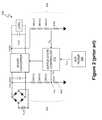
- FIG. 1represents a power control system 100 , which includes a switching power converter 102 .
- Voltage source 101supplies an alternating current (AC) input voltage V in (t) to a full bridge diode rectifier 103 .
- the voltage source 101is, for example, a public utility, and the AC voltage V in (t) is, for example, a 60 Hz/110 V line voltage in the United States of America or a 50 Hz/220 V line voltage in Europe.
- the rectifier 103rectifies the input voltage V in (t) and supplies a rectified, time-varying, line input voltage V X (t) to the switching power converter.
- the switching power converter 102includes power factor correction (PFC) stage 124 and driver stage 126 .
- the switching power converter 102includes at least two switching operations, i.e. switching switch 108 to provide power factor correction and switching switch 108 to provide regulation of output voltage V O (t).
- the PFC stage 124is controlled by switch 108 and provides power factor correction.
- the driver stage 126is also controlled by switch 108 and regulates the transfer of energy from the line input voltage V X (t) through inductor 110 to capacitor 106 .
- the inductor current i Lramps ‘up’ when the switch 108 conducts, i.e. is “ON”.
- the inductor current i Lramps down when switch 108 is nonconductive, i.e.
- the switching power converter 102operates in discontinuous current mode, i.e. ramp up time of the inductor current i L plus the inductor flyback time is less than the period of the control signal CS 0 , which controls the conductivity of switch 108 .
- control signal CS 0is a pulse width modulated signal
- the switch 108is a field effect transistor (FET), such as an n-channel FET.
- Control signal CS 0is a gate voltage of switch 108 , and switch 108 conducts when the pulse width of CS 0 is high.
- the ‘on-time’ of switch 108is determined by the pulse width of control signal CS 0 . Accordingly, the energy transferred to inductor 110 is proportionate to a square of the pulse width of control signal CS 0 .
- Capacitor 106supplies stored energy to load 112 .
- the capacitor 106is sufficiently large so as to maintain a substantially constant output voltage V C (t), as established by a switch state controller 114 (as discussed in more detail below).
- the output voltage V C (t)remains substantially constant during constant load conditions. However, as load conditions change, the output voltage V C (t) changes.
- the switch state controller 114responds to the changes in V C (t) and adjusts the control signal CS 0 to restore a substantially constant output voltage as quickly as possible.
- the switch state controller 114includes a small capacitor 115 to filter any high frequency signals from the line input voltage V X (t).
- the switch state controller 114 of power control system 100controls switch 108 and, thus, controls power factor correction and regulates output power of the switching power converter 102 .
- the goal of power factor correction technologyis to make the switching power converter 102 appear resistive to the voltage source 101 .
- the switch state controller 114attempts to control the inductor current i L so that the average inductor current i L is linearly and directly related to the line input voltage V X (t).
- Prodi ⁇Compensator Design and Stability Assessment for Fast Voltage Loops of Power Factor Correction Rectifiers , IEEE Transactions on Power Electronics, Vol. 22, No. 5, September 2007, pp. 1719-1729 (referred to herein as “Prodi ⁇ ”), describes an example of switch state controller 114 .
- the switch state controller 114supplies the pulse width modulated (PWM) control signal CS 0 to control the conductivity of switch 108 .
- PWMpulse width modulated
- the values of the pulse width and duty cycle of control signal CS odepend on sensing two signals, namely, the line input voltage V X (t) and the capacitor voltage/output voltage V C (t).
- Switch state controller 114receives the two voltage signals, the line input voltage V X (t) and the output voltage V C (t), via a wide bandwidth current loop 116 and a slower voltage loop 118 .
- the line input voltage V X (t)is sensed from node 120 between the diode rectifier 103 and inductor 110 .
- the output voltage V C (t)is sensed from node 122 between diode 111 and load 112 .
- the current loop 116operates at a frequency f c that is sufficient to allow the switch state controller 114 to respond to changes in the line input voltage V X (t) and cause the inductor current i L to track the line input voltage to provide power factor correction.
- the current loop frequencyis generally set to a value between 20 kHz and 130 kHz.
- the voltage loop 118operates at a much slower frequency f v , typically 10-20 Hz. By operating at 10-20 Hz, the voltage loop 118 functions as a low pass filter to filter an alternating current (AC) ripple component of the output voltage V C (t).
- ACalternating current
- the switch state controller 114controls the pulse width (PW) and period (TT) of control signal CS 0 .
- PWpulse width
- TTperiod
- switch state controller 114controls the nonlinear process of switching power converter 102 so that a desired amount of energy is transferred to capacitor 106 .
- the desired amount of energydepends upon the voltage and current requirements of load 112 .
- switch state controller 114varies the period of control signal CS 0 so that the input current i L tracks the changes in input voltage V X (t) and holds the output voltage V C (t) constant.
- switch state controller 114increases the period TT of control signal CS 0 , and as the input voltage V X (t) decreases, switch state controller 114 decreases the period of control signal CS 0 .
- the pulse width PW of control signal CS 0is adjusted to maintain a constant duty cycle (D) of control signal CS 0 , and, thus, hold the output voltage V C (t) constant.
- the switch state controller 114updates the control signal CS 0 at a frequency much greater than the frequency of input voltage V X (t).
- the frequency of input voltage V X (t)is generally 50-60 Hz.
- the frequency 1/TT of control signal CS 0is, for example, between 20 kHz and 130 kHz. Frequencies at or above 20 kHz avoid audio frequencies and frequencies at or below 130 kHz avoid significant switching inefficiencies while still maintaining good power factor, e.g. between 0.9 and 1, and an approximately constant output voltage V C (t).
- Power control systemalso includes auxiliary power supply 128 .
- Auxiliary power supply 128is the primary power source for providing operating power to PFC and output voltage controller 114 . However, as subsequently discussed in more detail with reference to FIG. 3B , during certain power loss conditions, the auxiliary power supply 128 is unable to provide sufficient operating power to PFC and output voltage controller 114 .
- FIG. 2depicts power control system 100 using voltage sensing.
- the power control system 100includes series coupled resistors 202 to sense the input voltage V X (t) and generate an input sense voltage Vsx.
- the series coupled resistors 202form a voltage divider, and the input sense voltage Vsx is sensed across the last resistor 204 .
- the voltage divideruses multiple resistors because input voltage V X (t) is generally higher than the voltage rating of individual resistors.
- Using a series of resistorsallows the voltage across each resistor to remain within the voltage rating of the resistors.
- 300 kohm resistorsas the first three resistors and a 9 kohm last resistor 204 , the input sense voltage is 0.01 ⁇ V X (t).
- the output voltage V out (t)is sensed in the same manner using series coupled resistors 206 as a voltage divider to generate an output sense voltage Vso.
- FIG. 3Adepicts the switch state controller 114 with two analog-to-digital converters (ADCs) 302 and 304 .
- ADCs 302 and 304convert respective sense voltages Vsx and Vso to respective digital output voltages V x (n) and V O (n) using a reference voltage V REF .
- the reference voltagecan be a bandgap developed voltage reference.
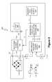
- FIG. 3Bdepicts a power supply system 350 .
- the power supply system 350includes switching power converter 102 to provide power factor correction and to provide output voltage V O (t).
- Output voltage V O (t)is the same as output voltage V c (t) in FIG. 1 .
- the power supply system 350provides power to a load 353 that can enter a very low power state (such as a standby-mode) or completely ‘off’ state. Examples of load 353 are computer systems or other data processing systems.
- switching power converter 102is ‘on’ and performs a boost converter function to boost the input voltage V x (t) from, e.g. 130V, to generate output voltage V O (t), such as +400V.
- the output voltage V O (t)is provided to the main power supply 354 and to the standby power supply 352 .
- “Normal” operationis when the power supply 350 is not in a low-power or ‘off’ state.
- the main power supply 354provides a variety of voltages, such as +3V, +5V, and +12V, to power various components of load 353 during normal operation.
- the auxiliary power supply 128provides primary power to switch state controller 114 .
- the switch state controller 114includes an input to receive the power from auxiliary power supply 128 . However, during certain power loss conditions, auxiliary power supply 128 provides insufficient operating power to switch state controller 114 . During such power loss conditions, switch state controller 114 becomes inoperative.
- the power loss conditionsinclude a standby-mode when auxiliary power supply 128 is intentionally shut-down to save power. Power loss conditions also occur when switching power converter 102 is inoperative. In at least one embodiment, auxiliary power supply 128 receives power from switching power converter 102 . Thus, when switching power converter 102 is inoperative, such as during a missed cycle of input voltage V X (t), auxiliary power supply 128 provides insufficient operating power to switch state controller 114 .
- Voltage regulators and other componentscan be connected between auxiliary power supply 128 and switch state controller 114 .
- the standby power supply 352supplies, for example, up to 5 W of power to load 353 .
- the main power supply 354supplies, for example, up to 500 W of power. The particular amount of power supplied by the standby power supply 352 and the main power supply 354 are a matter of design choice.
- Each of the components 102 , 114 , 352 , 354 , and 128include an underlined state, i.e. ON or OFF, that represents the state of the components 102 , 114 , 352 , 354 , and 128 in standby mode.
- standby-modeonly the standby power supply 352 is ON.
- the standby power supply 352provides an auxiliary output voltage V A that provides power to circuits (not shown) that operate during low power states, such as standby-mode monitoring circuits.
- the standby power supply 352also provides power to components of load 353 that are used to initialize other components of load 353 as the components enter normal operation.
- the standby power supply 352must be designed to provide output power from voltages ranging from V x (t) to V O (t), such as +130V to +400V.
- the resulting standby power supply 352is, thus, generally less efficient than a power supply designed to operate with an approximately constant input voltage.
- an apparatusin one embodiment, includes a controller.
- the controlleris configured to operate during at least one controller operational mode from an operating voltage generated from at least a first portion of the first sense current, wherein the first sense current is resistively derived from a first voltage sense of a switching power converter.
- the controlleris also configured to receive at least a second portion of the first sense current and use the second portion of the first sense current to control a switching operation of the switching power converter.
- a methodin another embodiment, includes operating the controller during at least one controller operational mode from an operating voltage generated from at least a first portion of the first sense current, wherein the first sense current is resistively derived from a first voltage sense of a switching power converter. The method also includes receiving in a controller at least a second portion of the first sense current and using the second portion of the first sense current to control a switching operation of the switching power converter.
- an apparatusin a further embodiment, includes means for operating the controller during at least one controller operational mode from an operating voltage generated from at least a first portion of the first sense current, wherein the first sense current is resistively derived from a first voltage sense of a switching power converter.
- the apparatusalso includes means for receiving in a controller at least a second portion of the first sense current and means for using the second portion of the first sense current to control a switching operation of the switching power converter.
- FIG. 1(labeled prior art) depicts a power control system.
- FIG. 2(labeled prior art) depicts a power control system with voltage sensing.
- FIG. 3A(labeled prior art) depicts a switch state controller of the power control system of FIG. 2 that includes analog-to-digital converters to convert input and output sense voltages into a digital signal.
- FIG. 3B(labeled prior art) depicts a power supply system.
- FIG. 4depicts a power control system with current sensing.
- FIG. 6depicts a current sensing system.
- FIG. 7depicts a resistive impedance for current sensing.
- FIG. 8depicts an analog-to-digital converter.
- FIG. 9depicts a time division based secondary auxiliary power supply system.
- FIG. 10depicts a proportional division secondary auxiliary power supply system
- FIG. 11depicts a power supply system that uses one or more sense currents to supply power to an integrated circuit switch state controller at least when the power supply system is operating in standby-mode.
- FIG. 12depicts an exemplary graphical curve showing sense current power plotted versus output power of a switching power converter.
- a power supply system and methodinclude a switch state controller that is operational to control a switching power converter during certain power loss conditions that cause conventional switch state controllers to have diminished or no functionality.
- the auxiliary power supply for the switch state controllerdoes not provide sufficient operating power to the switch state controller during certain power loss conditions.
- poweris generated for the switch state controller using sense input and/or sense output currents of the switching power converter to allow a switch state controller to generate a control signal to control a switch of the switching power converter.
- the switch state controlleris fabricated as an integrated circuit (IC).
- the switch state controllerremains operational to cause the switching power converter to supply an approximately constant output voltage to, for example, a standby power supply that provides power to a load.
- the standby power supplycan be designed to operate more efficiently than a standby power supply designed to operate with a wide range of input voltages.
- the power supplied to the switch state controller by the sense current(s)is proportional to the output voltage of the switching power converter. As the output power of the switching power converter increases, the increased power demand for the switch state controller is provided by the auxiliary power supply.
- the sense current(s)can be used to provide power to the switch state controller.
- the sense current(s)can provide power to the switch state controller during certain power loss conditions when auxiliary IC power is unavailable or diminished, such as during start-up of the switch state controller or during input voltage missed cycles.
- the ICdraws more sense current from an input of the power control system than the output of the power control system to, for example, minimize any impact on the output voltage of the power supply. Also, by sensing sense currents, the power control system can eliminate at least one sense resistor used in a voltage sense system.
- FIG. 4depicts a power control system 400 with current sensing.
- a full diode bridge AC rectifier 402rectifies line input voltage V in (t) to generate a rectified input voltage V X (t).
- the input voltage V in (t)is the same as the input voltage V in (t) in FIG. 1 .
- Switching power converter 404represents one embodiment of a switching power converter that converts the rectified input voltage V X (t) into a direct current (DC) output voltage V O (t) for load 406 .
- Switching power converter 404can be any type of switching power converter, such as a boost converter or a buck converter.
- the switching power converter 404includes at least two switching operations, i.e.
- the output voltage V O (t)is the same as the output voltage V C (t) of FIG. 1 .
- the value of the output voltage V O (t)depends on the input voltage requirements of load 406 .
- the output voltage V O (t)is approximately 400 V.
- the switch state controller 408uses data representing the line input voltage V X (t) and the output voltage V O (t) to generate control signal C S .
- Voltages V X (t) and V O (t)are dropped across respective resistances R 0 and R 1 to generate sense currents i X and i O .
- Sense currents i X and i Orespectively represent the line input voltage V X (t) and the output voltage V O (t).
- a secondary auxiliary power supply 405generates an operating voltage V DD using one or both of sense currents i X and i O .
- Operating voltage V DDcan, for example, be supplied to the same external input, such as an IC pin, that receives the operating voltage V AUX , to a different external input of switch state controller 408 , or to an internal input of switch state controller 408 .
- auxiliary power supply 410 and secondary auxiliary power supply 405can combine to generate the operating voltage for switch state controller 408 .
- the secondary auxiliary power supply 405is physically separate from switch state controller 408 .
- the secondary auxiliary power supply 405is included in the same integrated circuit as switch state controller 408 . Exemplary resistances R 0 and R 1 are subsequently discussed in more detail.
- switch state controller 408is fabricated as an IC.
- the control signal C Scan be generated in any of a variety of ways, such as the exemplary ways described in U.S. patent application Ser. No. 11/967,271, entitled “Power Factor Correction Controller With Feedback Reduction”, inventor John L. Melanson, and assignee Cirrus Logic, Inc. (“Melanson I”) and U.S. patent application Ser. No. 11/967,272, entitled “Power Factor Correction Controller With Switch Node Feedback”, inventor John L. Melanson, and assignee Cirrus Logic, Inc. (“Melanson II”). Melanson I and Melanson II are incorporated herein by reference in their entireties.
- both the input voltage V X (t) and the output voltage V O (t)are sensed using both sense currents i X and i O . In at least one embodiment, only one or the other of input voltage V X (t) and output voltage V O (t) are sensed as currents.
- FIG. 5depicts a boost converter 500 , which represents one embodiment of switching power converter 404 .
- Boost converter 500includes inductor 110 , diode 111 , and switch 108 and functions as described with reference to the same components in FIG. 1 .
- FIG. 6depicts exemplary current sensing system 600 .
- the input voltage V X (t)is dropped across resistive impedance R 0 , and the sense current i X is provided as an input to ADC 602 .
- the output voltage V O (t)is dropped across resistive impedance R 1 , and the sense current i O is provided as an input to ADC 604 .
- R 0R 1
- R 0is less than R 1 .
- the implementation and values of resistive impedances R 0 and R 1are a matter of design choice and are discussed subsequently in more detail.
- ADC 602 and ADC 604convert respective sense currents i X and i O into respective digital values i X (n) and i O (n). Signals i X (n) and i O (n) are used by switch state controller 408 to generate control signal Cs as, for example, described in Melanson I and Melanson II.
- FIG. 7depicts an exemplary resistive impedance R, which represents an exemplary embodiment of resistive impedances R 0 and R 1 .
- the voltages across resistive impedances R 0 and R 1can be larger than the reliability voltage rating of individual resistors. Accordingly, in at least one embodiment, resistive impedance R is implemented with series coupled resistors R A , R B , and R C to lower the voltage drop across any particular resistor. Resistive impedance R is depicted with three (3) resistors. However, the exact number is a matter of design choice and depends, for example, on the resistor components used to implement resistive impedance R. Resistive impedance R can be implemented using one or more active components (such as FETs), one or more passive components (such as resistors), or both active and resistive components.
- active componentssuch as FETs
- passive componentssuch as resistors
- FIG. 8depicts ADC 800 , which represents an exemplary embodiment of ADC 602 and ADC 604 .
- the input current i inrepresents sense current i X for ADC 602 and sense current i O for ADC 604 .
- Current digital-to-analog converter (DAC) 802provides a DAC reference current i ref to node 804 .
- the difference current i Drepresents a difference between the input current i in and the DAC reference current i REF .
- the difference current i Dgenerates a voltage V D across resistor R 3 , and the voltage V D is compared to a reference voltage V REF , such as +2V by comparator 806 .
- the comparator 806generates a comparison voltage V C as an input to successive approximation register (SAR) 808 .
- SAR 808individually controls the conductivity of switches 810 - 818 of current DAC 802 .
- the current DACincludes current sources 820 - 828 .
- the value of the output currents of each successive current sourcedoubles the previous output current value.
- SAR 808uses, for example, any well-known logic algorithms to generate a digital output signal i(n) representing the analog input signal i IN .
- FIG. 9depicts a secondary auxiliary power supply system 900 for switch state controller 408 .
- Secondary auxiliary power supply system 900represents one embodiment of secondary auxiliary power supply system 405 .
- a primary auxiliary power supply 410provides an operating voltage, auxiliary voltage V AUX , to switch state controller 408 .
- Voltage V AUXis, for example, +15V.
- the operating power used by the controlleris greater than the power available from the primary auxiliary power supply 410 .
- the secondary auxiliary power supply system 900uses the sense currents i X and i O to generate a power supply voltage V DD for switch state controller 408 .
- the secondary auxiliary power supply system 900uses the sense currents i X and i O to generate a power supply voltage V DD for switch state controller 408 .
- the switch state controller 408uses sense signals i X (n) and i O (n) only a small fraction of the time during the operation of power control system 400 .
- Switch state controller 408closes switches (e.g. n-channel CMOS transistors) 902 and 904 using respective control signals C SAM0 and C SAM1 to sense the sense currents i X and i O from which respective sense current signals i X (n) and i O (n) are generated.
- Switches 902 and 904are primarily open. While switches 902 and 904 are open, the sense currents i O and i X are available to charge capacitor 906 through respective diodes 908 and 910 .
- the voltage developed across capacitor 906is the power supply voltage V DD to provide power to switch state controller 408 .
- the voltage V DDis regulated to, e.g. +15V, by, for example, a Zener diode 912 .
- the voltage V DDis the primary voltage supply for switch state controller 408 during start-up of switch state controller 408 and supplements the power delivered by auxiliary power supply 410 when auxiliary power supply 410 is not capable of supplying sufficient operating power to switch state controller 408 .
- the power delivered by secondary auxiliary power supply system 900is proportional to the output power delivered by power control system 400 .
- the secondary auxiliary power supply system 900can be entirely or partially included within switch state controller 408 . For example, in at least one embodiment, all components of the secondary auxiliary power supply system 900 except capacitor 906 are included within switch state controller 408 .
- secondary auxiliary power supply system 900draws more current from the input side of switching power converter 404 than the output side. Generally, drawing more power from the input side causes less fluctuation in the output voltage V O (t).
- the resistive impedance R 0is set less than the resistive impedance R 1 .
- the values of resistors R 0 and R 1are matters of design choice. Exemplary, respective values for R 0 and R 1 are 400 kohms and 4 Mohms.
- the ADC 602 and ADC 604are still able to provide the sense data to switch state controller 408 to allow switch state controller 408 to properly generate control signal Cs.
- FIG. 10depicts secondary auxiliary power supply system 1000 , which represents another embodiment of secondary auxiliary power supply 405 .
- Secondary auxiliary power supply system 1000supplies auxiliary power to switch state controller 408 during at least a portion of the operational time of switch state controller 408 , such as when auxiliary power supply 410 cannot provide sufficient power to allow switch state controller 408 to operate.
- switch state controller 408uses only a fraction of the energy available from sense currents i X and i O to sense respective voltages V x (t) and V O (t).
- secondary auxiliary power supply system 1000can divide the energy available from sense currents i X and i O to supply operating power to switch state controller 408 and provide feedback sensing of respective voltages V x (t) and V O (t).
- secondary auxiliary power supply system 1000has two modes of operation: (1) Start Up Mode and (2) Normal Mode.
- Start Up Modeauxiliary power supply 410 provides insufficient operating power to switch state controller 408
- secondary auxiliary power supply system 1000provides operating power to switch state controller 408 by using energy from sense current i X , sense current i O , or both sense currents i X and i O .
- Secondary auxiliary power supply system 1000includes proportional divider circuits 1001 and 1002 to provide operating power to switch state controller 408 during Start Up Mode.
- proportional divider circuits 1001 and 1002proportionately divide respective sense currents i X and i O into (i) respective power currents i XP and i OP to provide power to switch state controller 408 , (ii) respective support circuit biasing currents i XB and i OB , and (iii) respective measurement currents i XM and i OM to sense respective voltages V X (t) and V O (t).
- Currents i XP and i OPflow through respective p-channel FET transistors 1018 and 1020 to replace charge consumed by switch state controller 408 by charging capacitor 1014 to maintain voltage V DD at node 1008 .
- Biasing currents i XB and i OBflow through p-channel FET transistors 1022 and 1024 to provide biasing to respective proportional divider circuits 1001 and 1002 .
- Measurement currents i XM and i OMflow through p-channel FET transistors 1026 and 1028 to measure respective voltages V X (t) and V O (t).
- the secondary auxiliary power supply system 1000includes resistors R 0 and R 1 , which, in at least one embodiment, are respective resistors R 0 and R 1 as described in conjunction with FIGS. 6 and 7 . Resistors R 0 and R 1 are connected to respective nodes 1004 and 1006 . In at least one embodiment, the secondary auxiliary power supply system 1000 is included in the integrated circuit with switch state controller 408 , and nodes 1004 and 1006 represent pins of the switch state controller 408 . In another embodiment, secondary auxiliary power supply system 1000 is physically separate from switch state controller 408 , and node 1008 is connected to a pin of switch state controller 408 to provide power to switch state controller 408 .
- the gates of transistors 1018 , 1022 , and 1026are interconnected, and the gates of transistors 1020 , 1024 , and 1028 are interconnected.
- the voltage V GX applied to gates of transistors 1018 , 1022 , and 1026controls the flow of current in proportional divider circuit 1001 during Start Up Mode and Normal Mode.
- the voltage V GO applied to gates of transistors 1020 , 1024 , and 1028controls the flow of current in proportional divider circuit 1002 during Start Up Mode and Normal Mode.
- Voltages V GX and V GOare controlled by the state of respective analog multiplexers 1030 and 1032 .
- the analog multiplexers 1030 and 1032are 2 input/1 output analog multiplexers with respective select signals SEL X and SEL O .
- the two input signals of analog multiplexers 1030 and 1032are voltages V DD and V BIAS .
- the respective outputs of analog multiplexers 1030 and 1032are voltages V GX and V GO .
- select signals SEL X and SEL OWhen not operating in Normal Mode, the state of select signals SEL X and SEL O is set to select voltage V DD . Thus, during Start Up Mode, voltages V GX and V GO equal voltage V DD .
- power current i XPequals sense current i X
- power current i OPequals sense current i O .
- the power currents i XP and i OP provided to node 1008charge capacitor 1014 to voltage V DD .
- Zener diode 1016limits the voltage across capacitor 1014 to voltage V DD .
- transistors 1018 , 1022 , and 1026 and 1020 , 1024 , and 1028remain OFF since the gate-to-source voltages V GS of transistors 1018 , 1022 , and 1026 and 1020 , 1024 , and 1028 is below V TH +V ON .
- V THrepresents the threshold voltage of transistors 1018 , 1022 , and 1026 and 1020 , 1024 , and 1028
- V ONrepresents the voltage above the threshold voltage V TH .
- the threshold voltage V THis at least 0.7 V
- voltage V ONis 100-200 mV.
- transistors 1018 , 1022 , and 1026 and 1020 , 1024 , and 1028are conductive, and the sense currents i X and i O will be shared between respective transistors 1018 , 1022 , and 1026 and 1020 , 1024 , and 1028 and respective diodes 1010 and 1012 .
- the geometries of transistors 1018 , 1022 , and 1026 , transistors 1020 , 1024 , and 1028 , and diodes 1010 and 1012cause respective power currents i XP and i OP to exceed measurement currents i XM and i OM and bias currents i XB and i OB .
- respective power currents i XP and i OPare approximately 90% of sense currents i X and i O .
- the state of multiplexer select signals SEL X and SEL Oselects voltage V BIAS as the voltage for gate voltages V GX and V GO .
- the value of voltage V BIAScauses sense currents i X and i O to only flow through transistors 1018 , 1022 , and 1026 and 1020 , 1024 , and 1028 .
- the current flowing through transistors 1018 , 1022 , and 1026 and 1020 , 1024 , and 1028is proportionally split between respective power currents i XP and i OP , bias currents i XB and i OB , and measurement currents i XM and i OM .
- the current division proportionsare a function of the physical dimensions of respective transistors 1018 , 1022 , and 1026 and 1020 , 1024 , and 1028 .
- the ratio of physical geometries and, thus, the current division proportionsallows a majority of the sense currents i X and i O to flow through respective transistors 1018 and 1020 to continue supplying energy to charge capacitor 1014 at node 1008 .
- the remaining current, i.e. i X -i XPin proportional divider circuit 1001 is divided between transistors 1022 and 1026 .
- the remaining current, i.e. i O -i OPin proportional divider circuit 1002 is divided between transistors 1024 and 1028 .
- the physical dimensions of transistor 1018is greater than the physical dimensions of transistor 1026 , and the physical dimensions of transistor 1026 is greater than the physical dimensions of transistor 1022 .
- the measurement current i XMis greater than the bias current i XB .
- the physical dimensions of transistor 1020is greater than the physical dimensions of transistor 1028 , and the physical dimensions of transistor 1028 is greater than the physical dimensions of transistor 1024 .
- the measurement current i OMis greater than the bias current i OB .
- the accuracy of current division by proportional divider circuits 1001 and 1002is determined by the ability of the respective drain bias regulators 1034 and 1036 to maintain the drains of respective transistors 1022 and 1026 at voltage V DD .
- Bias current i XBflows through p-channel FET 1038 to the diode connected n-channel FET 1040 .
- Transistor 1040 along with n-channel FET 1042form a current mirror whose output current i XP at the drain of transistor 1042 equals a scaled version of bias current i XB .
- the drain current of transistor 1042is presented to the diode connected p-channel FET 1044 to generate a cascode bias for driving transistor 1038 and p-channel FET 1046 .
- bias current i OBflows through p-channel FET 1048 to the diode connected n-channel FET 1050 .
- Transistor 1050 along with n-channel FET 1052form a current mirror whose output current i OP at the drain of transistor 1052 equals a scaled version of bias current i OB .
- the drain current of transistor 1052is presented to the diode connected p-channel FET 1054 to generate a cascode bias for driving transistor 1048 and p-channel FET 1056 .
- drain bias regulators 1034 and 1036provide the voltages used to cause respective proportional divider circuits 1001 and 1002 to proportionately divide respective sense currents i X and i O into power, measurement, and support bias currents.
- the respective voltages at nodes 1004 and 1006is less than voltage V BE of diodes 1010 and 1012 with reference to voltage V DD .
- the source to drain voltage of transistors 1018 , 1022 , and 1026 and 1020 , 1024 , and 1028is larger than voltage V ON , and voltage V ON is the voltage above the threshold voltage V TH of transistors 1018 , 1022 , and 1026 and 1020 , 1024 , and 1028 .
- voltage V ONis 100-200 mV.
- voltage V BIASis set equal to the threshold voltage V TH of transistors 1018 , 1022 , and 1026 and 1020 , 1024 , and 1028 .
- the difference between the threshold voltage V TH and the diode forward bias voltage V BEis generally ⁇ +/ ⁇ 200 mV. If the voltage V ON is greater than or equal to 100 mV and less than or equal to 200 mV, then a bipolar device of junction diode referenced to voltage V DD can be used to generate voltage V BIAS .
- the bias voltage V BIASis, thus, V DD -V BE .
- the voltage bias regulator 1058includes a diode connected bipolar junction transistor 1060 with an emitter connected to a current source 1062 .
- the voltage V BIASis the emitter voltage of transistor 1060 .
- Intput converter 1064receives measurement current i XM and converts the measurement current i XM into a signal representing voltage V X (t).
- Output converter 1064can be any conversion circuit such as ADC 800 , a current to voltage converter, or an analog conversion circuit.
- Output converter 1066receives measurement current i OM and converts the measurement current i OM into a signal representing voltage V O (t).
- Output converter 1066can be any conversion circuit such as ADC 800 , a current to voltage converter, or an analog conversion circuit.
- FIG. 11depicts one embodiment of a power supply system 1100 that uses one or more sense currents i X and i O , to supply power to switch state controller 1102 at least when power supply system 1100 is operating in standby-mode or in other situations when auxiliary power supply 410 does not provide sufficient operating power switch state controller 1102 .
- the input voltage V X (t)may miss one or more cycles causing auxiliary power supply 410 to provide insufficient operating power to switch state controller 1102 .
- Switch state controller 1102receives power from auxiliary power supply 410 via an input 1108 .
- Input 1108can be any type of connection capable of allowing auxiliary power supply 410 to provide power to switch state controller 1102 .
- the power supply system 1100includes a switching power converter 1104 , such as switching power converter 404 , that, in at least one embodiment, provides power factor correction and boosts the input voltage V x (t) to output voltage V O (t).
- a switching power converter 1104such as switching power converter 404
- input and output capacitorssuch as respective capacitors 115 and 106 ( FIG. 4 ) are included in power supply system 1100 but not shown in FIG. 11 for clarity.
- Standby secondary auxiliary power supply 1105supplies, for example, up to 5 W of power to load 353 while load 353 is in standby.
- Secondary auxiliary power supply 1105generates power supply voltage V DD for operating switch state controller 1102 during situations when primary auxiliary power supply 410 provides insufficient operating power to switch state controller 1102 .
- the secondary auxiliary power supply 1105enables switch state controller 1102 to operate during standby mode.
- Switch state controller 1102is able to operate during standby mode (and in other situations when auxiliary power supply 410 provides insufficient operating power to switch state controller 1102 ), and switching power converter 1104 maintains an approximately constant output voltage V O (t).
- standby power supply 1106can be designed to operate from an approximately constant input voltage and, thus, can be designed more cost effectively than standby power supplies designed to operate from a wider range of input voltages.
- secondary auxiliary power supply 1105for developing the auxiliary input voltage V DD to power the switch state controller 1102 , at least during standby-mode, is a matter of design choice.
- secondary auxiliary power supply 1105is secondary auxiliary power supply system 900 .
- secondary auxiliary power supply 1105is secondary auxiliary power supply system 1000 .
- Secondary auxiliary power supply 1105can be included as part of the IC containing switch state controller 1102 or can be physically separate from switch state controller 1102 and connected to switch state controller 1102 to provide voltage V DD ( FIGS. 9 and 10 ).
- secondary auxiliary power supply 1105can be implemented internally, externally, or a combination of internally and externally to the switch state controller 1102 .
- Each of the components 354 , 410 , 1102 , 1104 , and 1106includes an underlined state, i.e. ON or OFF, that represents the state of the components 354 , 410 , 1102 , 1104 , and 1106 in standby mode. Because the sense currents i X and i O are available in standby-mode, the switch state controller 1102 can remain ON. In standby-mode, the power factor correction control switch (such as switch 108 in FIG. 1 ) of switching power converter 1104 has a very small pulse width, and, thus, does not need to conduct very often. For example, the duty cycle of control signal Cs is very small during standby-mode and low power operation.
- the duty cycleis, for example, nearly 0% in standby-mode. Because of the low duty cycle of control signal Cs in standby-mode, the switch state controller 1102 requires less power to operate in standby-mode. Because of the low power requirement of switch state controller 1102 during standby-mode, the power derived from the sense current i X , i O , or i X and i O (i.e. sense currents i X and/or i O ) provides sufficient power to allow switch state controller 1102 to operate during standby-mode. During a missed cycle of input voltage V X (t), an output capacitor on an output of the switching power converter 1104 (such as capacitor 106 of FIG.
- the standby power supply 1106can be designed to operate efficiently with a constant input voltage V O (t) supply.
- the secondary auxiliary power supply 1105 for developing the auxiliary input voltage V DD to power the switch state controller 1102 , at least during standby-mode,is a matter of design choice.
- secondary auxiliary power supply 1105is secondary auxiliary power supply system 900 .
- secondary auxiliary power supply 1105is secondary auxiliary power supply system 1000 .
- the secondary auxiliary power supply 1105can be implemented internally, externally, or a combination of internally and externally to the switch state controller 1102 .
- FIG. 12depicts an exemplary graphical curve 1202 showing switch state controller power plotted versus output power of switching power converter 1104 .
- the exemplary switch state controller power curve 1202represents power provided by secondary auxiliary power supply 1105 from sense currents i X and/or i O and the auxiliary power supply 410 as the output power supplied by the switching power converter 1104 changes. As the output power supplied by the switching power converter 1104 increases, more power is supplied to the switch state controller 1102 from the auxiliary power supply 410 to allow the switch state controller 1102 to increase the pulse width of the control signal C S , and, thus, increase the power supplied by switching power converter 1104 .
- the power supplied to the switch state controller 1102 by the auxiliary power supply 410is proportional to the output power supplied by switching power converter 1104 .
- the exemplary switch state controller power curve 1202indicates that the sense currents i X and/or i O can provide sufficient energy to switch state controller 1102 to allow switch state controller 1102 to operate during times of low power demand on switching power converter 1104 .
- the power demand curve 1204 of switch state controller 1102indicates the power demand of the switch state controller 1102 from standby mode to normal operation mode.
- the switch state controllerenables the switching power converter to supply an approximately constant output voltage to a standby power supply.
Landscapes
- Engineering & Computer Science (AREA)
- Power Engineering (AREA)
- Dc-Dc Converters (AREA)
Abstract
Description
This application claims the benefit under 35 U.S.C. §119(e) and 37 C.F.R. §1.78 of U.S. Provisional Application No. 61/024,587, filed Jan. 30, 2008 and entitled “Power Factor Correction with Boost Function Active in Standby Mode.” U.S. Provisional Application No. 61/024,587 includes exemplary systems and methods and is incorporated by reference in its entirety.
1. Field of the Invention
The present invention relates in general to the field of signal processing, and, more specifically, to a power control system that includes a switch state controller for a switching power converter that operates in at least some circumstances from an operating voltage derived from one or more sense currents. Each sense current is resistively derived from a voltage of the switching power converter.
2. Description of the Related Art
Power control systems often utilize a switching power converter to convert alternating current (AC) voltages to direct current (DC) voltages or DC-to-DC. Switching power converters often include a nonlinear energy transfer process to provide power factor corrected energy to a load. Power control systems provide power factor corrected and regulated output voltages to many devices that utilize a regulated output voltage.
Theswitching power converter 102 includes power factor correction (PFC)stage 124 anddriver stage 126. Theswitching power converter 102 includes at least two switching operations,i.e. switching switch 108 to provide power factor correction and switchingswitch 108 to provide regulation of output voltage VO(t). ThePFC stage 124 is controlled byswitch 108 and provides power factor correction. Thedriver stage 126 is also controlled byswitch 108 and regulates the transfer of energy from the line input voltage VX(t) throughinductor 110 tocapacitor 106. The inductor current iLramps ‘up’ when theswitch 108 conducts, i.e. is “ON”. The inductor current iLramps down whenswitch 108 is nonconductive, i.e. is “OFF”, and supplies current iLto rechargecapacitor 106. The time period during which inductor current iLramps down is commonly referred to as the “inductor flyback time”.Diode 111 prevents reverse current flow intoinductor 110. In at least one embodiment, theswitching power converter 102 operates in discontinuous current mode, i.e. ramp up time of the inductor current iLplus the inductor flyback time is less than the period of the control signal CS0, which controls the conductivity ofswitch 108.
Input current iLis proportionate to the ‘on-time’ ofswitch 108, and the energy transferred toinductor 110 is proportionate to the ‘on-time’ squared. Thus, the energy transfer process is one embodiment of a nonlinear process. In at least one embodiment, control signal CS0is a pulse width modulated signal, and theswitch 108 is a field effect transistor (FET), such as an n-channel FET. Control signal CS0is a gate voltage ofswitch 108, and switch108 conducts when the pulse width of CS0is high. Thus, the ‘on-time’ ofswitch 108 is determined by the pulse width of control signal CS0. Accordingly, the energy transferred toinductor 110 is proportionate to a square of the pulse width of control signal CS0.
Capacitor106 supplies stored energy to load112. Thecapacitor 106 is sufficiently large so as to maintain a substantially constant output voltage VC(t), as established by a switch state controller114 (as discussed in more detail below). The output voltage VC(t) remains substantially constant during constant load conditions. However, as load conditions change, the output voltage VC(t) changes. Theswitch state controller 114 responds to the changes in VC(t) and adjusts the control signal CS0to restore a substantially constant output voltage as quickly as possible. Theswitch state controller 114 includes asmall capacitor 115 to filter any high frequency signals from the line input voltage VX(t).
Theswitch state controller 114 ofpower control system 100controls switch 108 and, thus, controls power factor correction and regulates output power of theswitching power converter 102. The goal of power factor correction technology is to make theswitching power converter 102 appear resistive to thevoltage source 101. Thus, theswitch state controller 114 attempts to control the inductor current iLso that the average inductor current iLis linearly and directly related to the line input voltage VX(t). Prodić,Compensator Design and Stability Assessment for Fast Voltage Loops of Power Factor Correction Rectifiers, IEEE Transactions on Power Electronics, Vol. 22, No. 5, September 2007, pp. 1719-1729 (referred to herein as “Prodić”), describes an example ofswitch state controller 114. Theswitch state controller 114 supplies the pulse width modulated (PWM) control signal CS0to control the conductivity ofswitch 108. The values of the pulse width and duty cycle of control signal CSodepend on sensing two signals, namely, the line input voltage VX(t) and the capacitor voltage/output voltage VC(t).
Theswitch state controller 114 controls the pulse width (PW) and period (TT) of control signal CS0. Thus,switch state controller 114 controls the nonlinear process of switchingpower converter 102 so that a desired amount of energy is transferred tocapacitor 106. The desired amount of energy depends upon the voltage and current requirements ofload 112. To regulate the amount of energy transferred and maintain a power factor close to one,switch state controller 114 varies the period of control signal CS0so that the input current iLtracks the changes in input voltage VX(t) and holds the output voltage VC(t) constant. Thus, as the input voltage VX(t) increases,switch state controller 114 increases the period TT of control signal CS0, and as the input voltage VX(t) decreases,switch state controller 114 decreases the period of control signal CS0. At the same time, the pulse width PW of control signal CS0is adjusted to maintain a constant duty cycle (D) of control signal CS0, and, thus, hold the output voltage VC(t) constant. In at least one embodiment, theswitch state controller 114 updates the control signal CS0at a frequency much greater than the frequency of input voltage VX(t). The frequency of input voltage VX(t) is generally 50-60 Hz. The frequency 1/TT of control signal CS0is, for example, between 20 kHz and 130 kHz. Frequencies at or above 20 kHz avoid audio frequencies and frequencies at or below 130 kHz avoid significant switching inefficiencies while still maintaining good power factor, e.g. between 0.9 and 1, and an approximately constant output voltage VC(t). Power control system also includesauxiliary power supply 128.Auxiliary power supply 128 is the primary power source for providing operating power to PFC andoutput voltage controller 114. However, as subsequently discussed in more detail with reference toFIG. 3B , during certain power loss conditions, theauxiliary power supply 128 is unable to provide sufficient operating power to PFC andoutput voltage controller 114.
Voltage regulators and other components (not shown) can be connected betweenauxiliary power supply 128 and switchstate controller 114. Thestandby power supply 352 supplies, for example, up to 5 W of power to load353. Themain power supply 354 supplies, for example, up to 500 W of power. The particular amount of power supplied by thestandby power supply 352 and themain power supply 354 are a matter of design choice.
Each of thecomponents components standby power supply 352 is ON. In standby-mode, thestandby power supply 352 provides an auxiliary output voltage VAthat provides power to circuits (not shown) that operate during low power states, such as standby-mode monitoring circuits. Thestandby power supply 352 also provides power to components ofload 353 that are used to initialize other components ofload 353 as the components enter normal operation.
Because switchingpower converter 102 is ‘off’ during standby-mode, the output voltage VO(t) drops to the input voltage Vx(t). Thus, thestandby power supply 352 must be designed to provide output power from voltages ranging from Vx(t) to VO(t), such as +130V to +400V. The resultingstandby power supply 352 is, thus, generally less efficient than a power supply designed to operate with an approximately constant input voltage. Thus, there is a need for a switching power converter that can provide an approximately constant input voltage when operating.
In one embodiment of the present invention, an apparatus includes a controller. The controller is configured to operate during at least one controller operational mode from an operating voltage generated from at least a first portion of the first sense current, wherein the first sense current is resistively derived from a first voltage sense of a switching power converter. The controller is also configured to receive at least a second portion of the first sense current and use the second portion of the first sense current to control a switching operation of the switching power converter.
In another embodiment of the present invention, a method includes operating the controller during at least one controller operational mode from an operating voltage generated from at least a first portion of the first sense current, wherein the first sense current is resistively derived from a first voltage sense of a switching power converter. The method also includes receiving in a controller at least a second portion of the first sense current and using the second portion of the first sense current to control a switching operation of the switching power converter.
In a further embodiment of the present invention, an apparatus includes means for operating the controller during at least one controller operational mode from an operating voltage generated from at least a first portion of the first sense current, wherein the first sense current is resistively derived from a first voltage sense of a switching power converter. The apparatus also includes means for receiving in a controller at least a second portion of the first sense current and means for using the second portion of the first sense current to control a switching operation of the switching power converter.
The present invention may be better understood, and its numerous objects, features and advantages made apparent to those skilled in the art by referencing the accompanying drawings. The use of the same reference number throughout the several figures designates a like or similar element.
A power supply system and method include a switch state controller that is operational to control a switching power converter during certain power loss conditions that cause conventional switch state controllers to have diminished or no functionality. In at least one embodiment, during certain power loss conditions, such as when an auxiliary power supply is in standby mode or when the switching power converter is not operating, the auxiliary power supply for the switch state controller does not provide sufficient operating power to the switch state controller during certain power loss conditions. In at least one embodiment, during such power loss conditions, power is generated for the switch state controller using sense input and/or sense output currents of the switching power converter to allow a switch state controller to generate a control signal to control a switch of the switching power converter. In at least one embodiment, the switch state controller is fabricated as an integrated circuit (IC).
Thus, during converter power supply power loss conditions, the switch state controller remains operational to cause the switching power converter to supply an approximately constant output voltage to, for example, a standby power supply that provides power to a load. By supplying the standby power supply with an approximately constant output voltage during standby and normal operational modes, the standby power supply can be designed to operate more efficiently than a standby power supply designed to operate with a wide range of input voltages. In at least one embodiment, the power supplied to the switch state controller by the sense current(s) is proportional to the output voltage of the switching power converter. As the output power of the switching power converter increases, the increased power demand for the switch state controller is provided by the auxiliary power supply.
Thus, in at least one embodiment, the sense current(s) can be used to provide power to the switch state controller. In at least one embodiment, the sense current(s) can provide power to the switch state controller during certain power loss conditions when auxiliary IC power is unavailable or diminished, such as during start-up of the switch state controller or during input voltage missed cycles. In at least one embodiment, the IC draws more sense current from an input of the power control system than the output of the power control system to, for example, minimize any impact on the output voltage of the power supply. Also, by sensing sense currents, the power control system can eliminate at least one sense resistor used in a voltage sense system.
The control signal CScan be generated in any of a variety of ways, such as the exemplary ways described in U.S. patent application Ser. No. 11/967,271, entitled “Power Factor Correction Controller With Feedback Reduction”, inventor John L. Melanson, and assignee Cirrus Logic, Inc. (“Melanson I”) and U.S. patent application Ser. No. 11/967,272, entitled “Power Factor Correction Controller With Switch Node Feedback”, inventor John L. Melanson, and assignee Cirrus Logic, Inc. (“Melanson II”). Melanson I and Melanson II are incorporated herein by reference in their entireties. In at least one embodiment, both the input voltage VX(t) and the output voltage VO(t) are sensed using both sense currents iXand iO. In at least one embodiment, only one or the other of input voltage VX(t) and output voltage VO(t) are sensed as currents.
In at least one embodiment, theswitch state controller 408 uses sense signals iX(n) and iO(n) only a small fraction of the time during the operation ofpower control system 400.Switch state controller 408 closes switches (e.g. n-channel CMOS transistors)902 and904 using respective control signals CSAM0and CSAM1to sense the sense currents iXand iOfrom which respective sense current signals iX(n) and iO(n) are generated.Switches switches capacitor 906 throughrespective diodes capacitor 906 is the power supply voltage VDDto provide power to switchstate controller 408. The voltage VDDis regulated to, e.g. +15V, by, for example, aZener diode 912. In at least one embodiment, the voltage VDDis the primary voltage supply forswitch state controller 408 during start-up ofswitch state controller 408 and supplements the power delivered by auxiliary power supply410 when auxiliary power supply410 is not capable of supplying sufficient operating power to switchstate controller 408. In at least one embodiment, the power delivered by secondary auxiliarypower supply system 900 is proportional to the output power delivered bypower control system 400. The secondary auxiliarypower supply system 900 can be entirely or partially included withinswitch state controller 408. For example, in at least one embodiment, all components of the secondary auxiliarypower supply system 900 exceptcapacitor 906 are included withinswitch state controller 408.
In at least one embodiment, secondary auxiliarypower supply system 900 draws more current from the input side of switchingpower converter 404 than the output side. Generally, drawing more power from the input side causes less fluctuation in the output voltage VO(t). To draw more current from the input side of switchingpower converter 404, the resistive impedance R0is set less than the resistive impedance R1. In at least one embodiment, R0is 10% of R1, i.e. R0=0.1 R1. The values of resistors R0and R1are matters of design choice. Exemplary, respective values for R0and R1are 400 kohms and 4 Mohms. TheADC 602 andADC 604 are still able to provide the sense data to switchstate controller 408 to allowswitch state controller 408 to properly generate control signal Cs.
In at least one embodiment, secondary auxiliarypower supply system 1000 has two modes of operation: (1) Start Up Mode and (2) Normal Mode. Referring toFIGS. 4 and 10 , in Start Up Mode, auxiliary power supply410 provides insufficient operating power to switchstate controller 408, and secondary auxiliarypower supply system 1000 provides operating power to switchstate controller 408 by using energy from sense current iX, sense current iO, or both sense currents iXand iO. Secondary auxiliarypower supply system 1000 includesproportional divider circuits state controller 408 during Start Up Mode. During Start Up Mode, all available energy from sense currents iXand iOis transferred by respectiveproportional divider circuits diodes capacitor 1014. The sense currents iXand iOchargecapacitor 1014 to voltage VDD, thus, raising the voltage ofnode 1008 to the operational voltage VDDofswitch state controller 408. The value ofcapacitor 1014 is a design choice and, in at least one embodiment, is chosen so that energy transfer from power currents iXPand iOPis sufficient to chargecapacitor 1014 to voltage VDDand provide sufficient operating power forswitch state controller 408 when auxiliary power supply410 provides insufficient operating power to switchstate controller 408.
During Normal Mode,proportional divider circuits state controller 408, (ii) respective support circuit biasing currents iXBand iOB, and (iii) respective measurement currents iXMand iOMto sense respective voltages VX(t) and VO(t). Currents iXPand iOPflow through respective p-channel FET transistors switch state controller 408 by chargingcapacitor 1014 to maintain voltage VDDatnode 1008. Biasing currents iXBand iOBflow through p-channel FET transistors 1022 and1024 to provide biasing to respectiveproportional divider circuits channel FET transistors 1026 and1028 to measure respective voltages VX(t) and VO(t).
The secondary auxiliarypower supply system 1000 includes resistors R0and R1, which, in at least one embodiment, are respective resistors R0and R1as described in conjunction withFIGS. 6 and 7 . Resistors R0and R1are connected torespective nodes power supply system 1000 is included in the integrated circuit withswitch state controller 408, andnodes switch state controller 408. In another embodiment, secondary auxiliarypower supply system 1000 is physically separate fromswitch state controller 408, andnode 1008 is connected to a pin ofswitch state controller 408 to provide power to switchstate controller 408.
The gates oftransistors 1018,1022, and1026 are interconnected, and the gates oftransistors transistors 1018,1022, and1026 controls the flow of current inproportional divider circuit 1001 during Start Up Mode and Normal Mode. The voltage VGOapplied to gates oftransistors proportional divider circuit 1002 during Start Up Mode and Normal Mode. Voltages VGXand VGOare controlled by the state ofrespective analog multiplexers
Theanalog multiplexers analog multiplexers analog multiplexers transistors transistors respective nodes nodes diodes diodes transistors diodes node 1008charge capacitor 1014 to voltage VDD. Zener diode1016 limits the voltage acrosscapacitor 1014 to voltage VDD.
During Start Up Mode,transistors transistors transistors transistors respective transistors respective diodes transistors 1018,1022, and1026,transistors diodes
During Normal Mode, the state of multiplexer select signals SELXand SELOselects voltage VBIASas the voltage for gate voltages VGXand VGO. In at least one embodiment, the value of voltage VBIAScauses sense currents iXand iOto only flow throughtransistors transistors
The current division proportions are a function of the physical dimensions ofrespective transistors respective transistors capacitor 1014 atnode 1008. The remaining current, i.e. iX-iXP, inproportional divider circuit 1001 is divided between transistors1022 and1026. The remaining current, i.e. iO-iOP, inproportional divider circuit 1002 is divided betweentransistors transistor 1018 is greater than the physical dimensions of transistor1026, and the physical dimensions of transistor1026 is greater than the physical dimensions of transistor1022. Thus, the measurement current iXMis greater than the bias current iXB. In at least one embodiment, the physical dimensions oftransistor 1020 is greater than the physical dimensions oftransistor 1028, and the physical dimensions oftransistor 1028 is greater than the physical dimensions oftransistor 1024. Thus, the measurement current iOMis greater than the bias current iOB.
The accuracy of current division byproportional divider circuits drain bias regulators channel FET 1038 to the diode connected n-channel FET 1040.Transistor 1040 along with n-channel FET 1042 form a current mirror whose output current iXPat the drain oftransistor 1042 equals a scaled version of bias current iXB. The drain current oftransistor 1042 is presented to the diode connected p-channel FET 1044 to generate a cascode bias for drivingtransistor 1038 and p-channel FET 1046. The bias forces the drain voltages of transistors1022 and1026 to voltage VDD, which matches the drain voltage oftransistor 1018. Bias current iOBflows through p-channel FET 1048 to the diode connected n-channel FET 1050.Transistor 1050 along with n-channel FET 1052 form a current mirror whose output current iOPat the drain oftransistor 1052 equals a scaled version of bias current iOB. The drain current oftransistor 1052 is presented to the diode connected p-channel FET 1054 to generate a cascode bias for drivingtransistor 1048 and p-channel FET 1056. The bias forces the drain voltages oftransistors transistor 1020. Thus, drainbias regulators proportional divider circuits
Typically, voltage VONis 100-200 mV. Thus, ideally, voltage VBIASis set equal to the threshold voltage VTHoftransistors transistors transistors
Thus, in at least one embodiment, thevoltage bias regulator 1058 includes a diode connectedbipolar junction transistor 1060 with an emitter connected to acurrent source 1062. The voltage VBIASis the emitter voltage oftransistor 1060.
The secondaryauxiliary power supply 1105 enablesswitch state controller 1102 to operate during standby mode.Switch state controller 1102 is able to operate during standby mode (and in other situations when auxiliary power supply410 provides insufficient operating power to switch state controller1102), and switchingpower converter 1104 maintains an approximately constant output voltage VO(t). Withswitch state controller 1102 operating in standby mode and switchingpower converter 1104 maintaining an approximately constant voltage VO(t),standby power supply 1106 can be designed to operate from an approximately constant input voltage and, thus, can be designed more cost effectively than standby power supplies designed to operate from a wider range of input voltages.
The particular secondaryauxiliary power supply 1105 for developing the auxiliary input voltage VDDto power theswitch state controller 1102, at least during standby-mode, is a matter of design choice. In at least one embodiment, secondaryauxiliary power supply 1105 is secondary auxiliarypower supply system 900. In another embodiment, secondaryauxiliary power supply 1105 is secondary auxiliarypower supply system 1000. Secondaryauxiliary power supply 1105 can be included as part of the IC containingswitch state controller 1102 or can be physically separate fromswitch state controller 1102 and connected to switchstate controller 1102 to provide voltage VDD(FIGS. 9 and 10 ). Thus, secondaryauxiliary power supply 1105 can be implemented internally, externally, or a combination of internally and externally to theswitch state controller 1102.
Each of thecomponents components switch state controller 1102 can remain ON. In standby-mode, the power factor correction control switch (such asswitch 108 inFIG. 1 ) of switchingpower converter 1104 has a very small pulse width, and, thus, does not need to conduct very often. For example, the duty cycle of control signal Cs is very small during standby-mode and low power operation. The duty cycle is, for example, nearly 0% in standby-mode. Because of the low duty cycle of control signal Cs in standby-mode, theswitch state controller 1102 requires less power to operate in standby-mode. Because of the low power requirement ofswitch state controller 1102 during standby-mode, the power derived from the sense current iX, iO, or iXand iO(i.e. sense currents iXand/or iO) provides sufficient power to allowswitch state controller 1102 to operate during standby-mode. During a missed cycle of input voltage VX(t), an output capacitor on an output of the switching power converter1104 (such ascapacitor 106 ofFIG. 4 ) is able to hold the output voltage VO(t) at an approximately constant value for at least several consecutive missed cycles. Missed cycles are generally sporadically dispersed among the cycles of input voltage VX(t). Because the sense current iOis derived from the output voltage VO(t), sense current iOis available during missed cycles of input voltage VX(t).
Becauseswitch state controller 1102 and switchingpower converter 1104 operate during standby-mode, thestandby power supply 1106 can be designed to operate efficiently with a constant input voltage VO(t) supply.
The secondaryauxiliary power supply 1105 for developing the auxiliary input voltage VDDto power theswitch state controller 1102, at least during standby-mode, is a matter of design choice. In at least one embodiment, secondaryauxiliary power supply 1105 is secondary auxiliarypower supply system 900. In another embodiment, secondaryauxiliary power supply 1105 is secondary auxiliarypower supply system 1000. The secondaryauxiliary power supply 1105 can be implemented internally, externally, or a combination of internally and externally to theswitch state controller 1102.
Thus, feedback input and/or output currents are available during standby-mode of the power supply, and, thus, the switch state controller enables the switching power converter to supply an approximately constant output voltage to a standby power supply.
Although the present invention has been described in detail, it should be understood that various changes, substitutions and alterations can be made hereto without departing from the spirit and scope of the invention.
Claims (30)
1. An apparatus comprising:
a controller, wherein the controller is configured to:
operate during at least one controller operational mode from an operating voltage generated from at least a first portion of a first sense current, wherein the first sense current is resistively derived from and senses at least one of: (i) a rectified input line voltage and (ii) an output voltage of a switching power converter, wherein the at least one controller operational mode comprises a start-up-mode of the controller;
receive at least a second portion of the first sense current concurrently with the first portion of the first sense current; and
use the second portion of the first sense current to control a switching operation of the switching power converter.
2. The apparatus ofclaim 1 wherein the switching operation of the switching power converter is a member of a group consisting of: (i) operating a switch of the switching power converter to provide power factor correction and (ii) operating the switch of the switching power converter to regulate an output voltage of the switching power converter.
3. The apparatus ofclaim 1 wherein the controller is configured to operate from the operating voltage generated from at least the first portion of the first sense current when a primary auxiliary power supply provides insufficient power to allow the controller to at least control an output voltage of the switching power converter.
4. The apparatus ofclaim 1 wherein the controller is further configured to cause the switching power converter to generate an approximately constant output voltage when the controller operates from the operating voltage generated from at least the first portion of the first sense current.
5. The apparatus ofclaim 1 wherein the controller is further configured to use at least the second portion of the first sense current to control at least one of (i) power factor correction of the switching power converter and (ii) regulation of an output voltage of the switching power converter.
6. The apparatus ofclaim 1 further comprising:
a secondary auxiliary power supply having a first input to receive at least the second portion of the first sense current, wherein the secondary auxiliary power supply system is configured to generate the operating voltage from at least the second portion of the first sense current.
7. The apparatus ofclaim 6 wherein the secondary auxiliary power supply and the controller comprise components included in an integrated circuit.
8. The apparatus ofclaim 1 wherein the controller is configured to operate from an operating voltage derived from at least the first sense current and derived from at least a second sense current, wherein the second sense current is resistively derived from a second voltage sense of the switching power converter.
9. The apparatus ofclaim 8 wherein the first sense current senses an input voltage to the switching power converter and the second sense current senses an output voltage of the switching power converter.
10. The apparatus ofclaim 8 wherein the controller includes a first converter to convert the first portion of the first sense current into data representing the input voltage to the switching power converter and a second converter to convert a second portion of the second sense current into data representing the output voltage of the switching power converter, wherein the apparatus further comprises:
a secondary auxiliary power supply, and the secondary auxiliary power supply comprises:
a first sense current proportional divider circuit coupled to the controller to provide the first portion of the first sense current to the first converter for sensing the input voltage of the switching power converter; and
a second sense current proportional divider circuit coupled to the controller to provide the second portion of the second sense current to the second converter for sensing the output voltage of the switching power converter;
wherein the first and second proportional divider circuits are configured to generate the operating voltage from the first portion of the first sense current and the second portion of the second sense current.
11. The apparatus ofclaim 8 the controller comprises:
a first converter to convert the second portion of the first sense current into data representing the input voltage of the switching power converter; and
a second converter to convert a second portion of the second sense current into data representing the output voltage of the switching power converter; and
the apparatus further comprises a secondary auxiliary power supply, and the second auxiliary apparatus comprises:
first circuitry coupled to the controller to provide the first sense current to the first converter for sensing the input voltage of the switching power converter and to at least contribute to generation of the operating voltage for the controller during non-overlapping periods of time; and
second circuitry coupled to the controller to provide the second sense current to the second converter for sensing the output voltage of the switching power converter and to at least contribute to generation of the operating voltage for the controller during non-overlapping periods of time.
12. The apparatus ofclaim 1 further comprising:
a secondary auxiliary power supply having a first input to receive at least the second portion of the first sense current and a second portion of a second sense current, wherein the second sense current is resistively derived from a second voltage sense of the switching power converter and the secondary auxiliary power supply system is configured to generate the operating voltage from at least the second portions of the first and second sense currents.
13. The apparatus ofclaim 12 further comprising:
a first resistive circuit, coupled between the input of the switching power converter and the second auxiliary power supply, to provide resistance to the first sense current; and
a second resistive circuit, coupled between an output of the switching power converter and the second auxiliary power supply, to provide resistance to the second sense current.
14. The apparatus ofclaim 13 wherein the second resistive circuit has a greater resistance than the first resistive circuit.
15. The apparatus ofclaim 1 wherein the first sense current is a member of a group consisting of: a sense current derived from an input voltage to the switching power converter and a sense current derived from the output voltage of the switching power converter.
16. The apparatus ofclaim 1 further comprising the switching power converter, wherein the switching power converter is coupled to the controller.
17. The apparatus ofclaim 16 wherein the switching power converter is a member of a group consisting of: a boost converter and a buck converter.
18. A method comprising:
operating a controller during at least one controller operational mode from an operating voltage generated from at least a first portion of a first sense current, wherein the first sense current is resistively derived from and senses at least one of: (i) a rectified input line voltage and (ii) an output voltage of a switching power converter, wherein the at least one controller operational mode comprises a start-up-mode of the controller;
receiving in the controller at least a second portion of the first sense current concurrently with the first portion of the first sense current; and
using the second portion of the first sense current to control a switching operation of the switching power converter.
19. The method ofclaim 18 wherein the switching operation of the switching power converter is a member of a group consisting of: operating a switch of the switching power converter to provide power factor correction and operating the switch of the switching power converter to regulate an output voltage of the switching power converter.
20. The method ofclaim 18 further comprising:
operating the controller to cause the switching power converter to generate an approximately constant output voltage when the controller operates from the operating voltage generated from at least the first portion of the first sense current.
21. The method ofclaim 18 operating the controller further comprises:
operating the controller from the operating voltage generated from at least the first portion of the first sense current when a primary auxiliary power supply provides insufficient power to allow the controller to at least control an output voltage of the switching power converter.
22. The method ofclaim 21 wherein the primary auxiliary power supply provides insufficient power to allow the controller to at least control an output voltage of the switching power converter during standby-mode of the power supply system.
23. The method ofclaim 18 wherein operating the controller further comprises:
operating the controller during at least one controller operational mode from an operating voltage generated from at least a first portion of the first sense current and generated from a first portion of a second sense current, wherein the second sense current is resistively derived from a second voltage sense of a switching power converter.
24. The method ofclaim 23 wherein operating the controller from the operating voltage generated from the first and second sense currents comprises operating the controller from the operating voltage generated from the first sense current and from a second sense current at least when a primary auxiliary power supply provides insufficient power to allow the controller to at least control an output voltage of the switching power converter.
25. The method ofclaim 23 further comprising:
providing the first sense current to the first converter for sensing the input voltage of the switching power converter and to at least contribute to generation of the operating voltage for the controller during non-overlapping periods of time; and
providing the second sense current to the second converter for sensing the output voltage of the switching power converter and to at least contribute to generation of the operating voltage for the controller during non-overlapping periods of time.
26. The method ofclaim 23 wherein the first sense current has a greater magnitude than the second sense current.
27. The method ofclaim 23 further comprising:
providing a second portion of the first sense current to a first converter for sensing the input voltage of the switching power converter while providing a first portion of the first sense current to a secondary auxiliary power supply system for generating the operating voltage.
28. The method ofclaim 23 wherein the first sense current is a member of a group consisting of: a sense current derived from an input voltage to the switching power converter and a sense current derived from the output voltage of the switching power converter.
29. The method ofclaim 18 further comprising:
determining a switch control signal to control a switch of the switching power converter, wherein the switch controls input current to the switching power converter.
30. An apparatus comprising:
means for operating a controller during at least one controller operational mode from an operating voltage generated from at least a first portion of a first sense current, wherein the first sense current is resistively derived from and senses at least one of: (i) a rectified input line voltage and (ii) an output voltage of a switching power converter, wherein the at least one controller operational mode comprises a start-up-mode of the controller;
means for receiving in the controller at least a second portion of the first sense current concurrently with the first portion of the first sense current; and
means for using the second portion of the first sense current to control a switching operation of the switching power converter.
Priority Applications (4)
| Application Number | Priority Date | Filing Date | Title |
|---|---|---|---|
| US12/165,556US8576589B2 (en) | 2008-01-30 | 2008-06-30 | Switch state controller with a sense current generated operating voltage |
| CN200980101628.8ACN101919144B (en) | 2008-01-30 | 2009-01-29 | Switch state controller with sense current generated operating voltage |
| GB1009005.8AGB2468239B (en) | 2008-01-30 | 2009-01-29 | Switch state controller with a sense current generated operating voltage |
| PCT/US2009/032358WO2009099867A1 (en) | 2008-01-30 | 2009-01-29 | Switch state controller with a sense current generated operating voltage |
Applications Claiming Priority (2)
| Application Number | Priority Date | Filing Date | Title |
|---|---|---|---|
| US2458708P | 2008-01-30 | 2008-01-30 | |
| US12/165,556US8576589B2 (en) | 2008-01-30 | 2008-06-30 | Switch state controller with a sense current generated operating voltage |
Publications (2)
| Publication Number | Publication Date |
|---|---|
| US20090189579A1 US20090189579A1 (en) | 2009-07-30 |
| US8576589B2true US8576589B2 (en) | 2013-11-05 |
Family
ID=40898546
Family Applications (1)
| Application Number | Title | Priority Date | Filing Date |
|---|---|---|---|
| US12/165,556Active2029-07-31US8576589B2 (en) | 2008-01-30 | 2008-06-30 | Switch state controller with a sense current generated operating voltage |
Country Status (4)
| Country | Link |
|---|---|
| US (1) | US8576589B2 (en) |
| CN (1) | CN101919144B (en) |
| GB (1) | GB2468239B (en) |
| WO (1) | WO2009099867A1 (en) |
Cited By (12)
| Publication number | Priority date | Publication date | Assignee | Title |
|---|---|---|---|---|
| US20140077718A1 (en)* | 2012-09-14 | 2014-03-20 | Lutron Electronics Co., Inc. | Two-wire dimmer with improved zero-cross detection |
| US20150061621A1 (en)* | 2013-09-05 | 2015-03-05 | Stmicroelectronics International N.V. | Low drop-out regulator with a current control circuit |
| US20150311894A1 (en)* | 2014-04-29 | 2015-10-29 | Allegro Microsystems, Llc | Systems and Methods for Sensing Current Through a Low-Side Field Effect Transistor |
| US9250669B2 (en) | 2012-09-14 | 2016-02-02 | Lutron Electronics Co., Inc. | Power measurement in a two-wire load control device |
| US9645220B2 (en) | 2014-04-17 | 2017-05-09 | Allegro Microsystems, Llc | Circuits and methods for self-calibrating or self-testing a magnetic field sensor using phase discrimination |
| US20170133865A1 (en)* | 2015-11-09 | 2017-05-11 | Industrial Technology Research Institute | Battery system and control method thereof |
| US20180097451A1 (en)* | 2015-04-13 | 2018-04-05 | Telcodium Inc. | Ideal diode bridge rectifying circuit and control method |
| US10581332B2 (en)* | 2017-08-09 | 2020-03-03 | Fuji Electric Co., Ltd. | Dimmer and power converter |
| US10746000B2 (en) | 2016-02-17 | 2020-08-18 | Halliburton Energy Services, Inc. | Wide-input-range downhole power supply |
| US11870348B1 (en)* | 2020-08-28 | 2024-01-09 | Empower Semiconductor, Inc. | High speed, low quiescent current comparator |
| WO2024167280A1 (en)* | 2023-02-08 | 2024-08-15 | 삼성전자주식회사 | Electronic device comprising pfc circuit, and control method therefor |
| US20240334574A1 (en)* | 2022-12-20 | 2024-10-03 | Electronic Theatre Controls, Inc. | Independent lighting control |
Families Citing this family (18)
| Publication number | Priority date | Publication date | Assignee | Title |
|---|---|---|---|---|
| US8013474B2 (en)* | 2006-11-27 | 2011-09-06 | Xslent Energy Technologies, Llc | System and apparatuses with multiple power extractors coupled to different power sources |
| US8212399B2 (en)* | 2006-11-27 | 2012-07-03 | Xslent Energy Technologies, Llc | Power extractor with control loop |
| US9431828B2 (en) | 2006-11-27 | 2016-08-30 | Xslent Energy Technologies | Multi-source, multi-load systems with a power extractor |
| US7960870B2 (en)* | 2006-11-27 | 2011-06-14 | Xslent Energy Technologies, Llc | Power extractor for impedance matching |
| US20100321968A1 (en)* | 2009-06-18 | 2010-12-23 | Hamilton Sundstrand Corporation | Load fault handling for switched reluctance or induction type machines |
| US8729811B2 (en) | 2010-07-30 | 2014-05-20 | Cirrus Logic, Inc. | Dimming multiple lighting devices by alternating energy transfer from a magnetic storage element |
| US9059641B2 (en)* | 2011-07-05 | 2015-06-16 | Atmel Corporation | Main supply zero crossing detection for PFC converter |
| CN102902332B (en)* | 2011-07-26 | 2015-04-29 | 中国长城计算机深圳股份有限公司 | Computer and power circuit thereof |
| EP2792037A2 (en) | 2011-12-14 | 2014-10-22 | Cirrus Logic, Inc. | Multi-mode flyback control for a switching power converter with dimmer |
| CN102664517B (en)* | 2012-05-08 | 2014-09-17 | 英飞特电子(杭州)股份有限公司 | Power factor correction circuit |
| US9161401B1 (en) | 2014-03-20 | 2015-10-13 | Cirrus Logic, Inc. | LED (light-emitting diode) string derived controller power supply |
| US9825546B2 (en)* | 2016-03-30 | 2017-11-21 | Infineon Technologies Austria Ag | Circuits and methods for auxiliary secondary supply generation with self-starting primary side driver in isolated power converters |
| DE102016224639A1 (en)* | 2016-12-09 | 2018-06-14 | Würth Elektronik eiSos Gmbh & Co. KG | Inverter device for energy production and power generator with such a converter device and use of such a converter device |
| CN107800310B (en)* | 2017-11-17 | 2020-07-10 | 上海新进半导体制造有限公司 | Power supply method of control chip in flyback switching power supply and control chip |
| TWI673590B (en)* | 2018-07-27 | 2019-10-01 | 威鋒電子股份有限公司 | Multi-port power supply apparatus and operation method thereof |
| CN109842975B (en)* | 2019-03-14 | 2025-01-14 | 江门市蓬江区天利新科技有限公司 | Light-emitting diode driving system based on power line transmission signal |
| WO2020255330A1 (en)* | 2019-06-20 | 2020-12-24 | 三菱電機株式会社 | Power conversion system |
| TWI746099B (en)* | 2020-08-03 | 2021-11-11 | 茂達電子股份有限公司 | Converter having fast transient response |
Citations (262)
| Publication number | Priority date | Publication date | Assignee | Title |
|---|---|---|---|---|
| US3316495A (en) | 1964-07-06 | 1967-04-25 | Cons Systems Corp | Low-level commutator with means for providing common mode rejection |
| US3423689A (en) | 1965-08-19 | 1969-01-21 | Hewlett Packard Co | Direct current amplifier |
| US3586988A (en) | 1967-12-01 | 1971-06-22 | Newport Lab | Direct coupled differential amplifier |
| US3725804A (en) | 1971-11-26 | 1973-04-03 | Avco Corp | Capacitance compensation circuit for differential amplifier |
| US3790878A (en) | 1971-12-22 | 1974-02-05 | Keithley Instruments | Switching regulator having improved control circuiting |
| US3881167A (en) | 1973-07-05 | 1975-04-29 | Pelton Company Inc | Method and apparatus to maintain constant phase between reference and output signals |
| US4075701A (en) | 1975-02-12 | 1978-02-21 | Messerschmitt-Bolkow-Blohm Gesellschaft Mit Beschrankter Haftung | Method and circuit arrangement for adapting the measuring range of a measuring device operating with delta modulation in a navigation system |
| GB2069269A (en) | 1980-02-11 | 1981-08-19 | Tektronix Inc | Supply voltage driver |
| US4334250A (en) | 1978-03-16 | 1982-06-08 | Tektronix, Inc. | MFM data encoder with write precompensation |
| US4409476A (en) | 1980-06-16 | 1983-10-11 | Asea Aktiebolag | Fiber optic temperature-measuring apparatus |
| US4414493A (en) | 1981-10-06 | 1983-11-08 | Thomas Industries Inc. | Light dimmer for solid state ballast |
| US4476706A (en) | 1982-01-18 | 1984-10-16 | Delphian Partners | Remote calibration system |
| US4523128A (en) | 1982-12-10 | 1985-06-11 | Honeywell Inc. | Remote control of dimmable electronic gas discharge lamp ballasts |
| US4677366A (en) | 1986-05-12 | 1987-06-30 | Pioneer Research, Inc. | Unity power factor power supply |
| US4683529A (en) | 1986-11-12 | 1987-07-28 | Zytec Corporation | Switching power supply with automatic power factor correction |
| US4700188A (en) | 1985-01-29 | 1987-10-13 | Micronic Interface Technologies | Electric power measurement system and hall effect based electric power meter for use therein |
| US4737658A (en) | 1985-08-05 | 1988-04-12 | Brown, Boveri & Cie Ag | Centralized control receiver |
| US4797633A (en) | 1987-03-20 | 1989-01-10 | Video Sound, Inc. | Audio amplifier |
| US4937728A (en) | 1989-03-07 | 1990-06-26 | Rca Licensing Corporation | Switch-mode power supply with burst mode standby operation |
| US4940929A (en) | 1989-06-23 | 1990-07-10 | Apollo Computer, Inc. | AC to DC converter with unity power factor |
| US4973919A (en) | 1989-03-23 | 1990-11-27 | Doble Engineering Company | Amplifying with directly coupled, cascaded amplifiers |
| US4979087A (en) | 1988-09-09 | 1990-12-18 | Aviation Limited | Inductive coupler |
| US4980898A (en) | 1989-08-08 | 1990-12-25 | Siemens-Pacesetter, Inc. | Self-oscillating burst mode transmitter with integral number of periods |
| US4992919A (en) | 1989-12-29 | 1991-02-12 | Lee Chu Quon | Parallel resonant converter with zero voltage switching |
| US4994952A (en) | 1988-02-10 | 1991-02-19 | Electronics Research Group, Inc. | Low-noise switching power supply having variable reluctance transformer |
| US5001620A (en) | 1988-07-25 | 1991-03-19 | Astec International Limited | Power factor improvement |
| US5055746A (en) | 1990-08-13 | 1991-10-08 | Electronic Ballast Technology, Incorporated | Remote control of fluorescent lamp ballast using power flow interruption coding with means to maintain filament voltage substantially constant as the lamp voltage decreases |
| US5109185A (en) | 1989-09-29 | 1992-04-28 | Ball Newton E | Phase-controlled reversible power converter presenting a controllable counter emf to a source of an impressed voltage |
| US5121079A (en) | 1991-02-12 | 1992-06-09 | Dargatz Marvin R | Driven-common electronic amplifier |
| US5206540A (en) | 1991-05-09 | 1993-04-27 | Unitrode Corporation | Transformer isolated drive circuit |
| US5264780A (en) | 1992-08-10 | 1993-11-23 | International Business Machines Corporation | On time control and gain circuit |
| US5278490A (en) | 1990-09-04 | 1994-01-11 | California Institute Of Technology | One-cycle controlled switching circuit |
| US5319301A (en) | 1984-08-15 | 1994-06-07 | Michael Callahan | Inductorless controlled transition and other light dimmers |
| US5321350A (en) | 1989-03-07 | 1994-06-14 | Peter Haas | Fundamental frequency and period detector |
| US5323157A (en) | 1993-01-15 | 1994-06-21 | Motorola, Inc. | Sigma-delta digital-to-analog converter with reduced noise |
| US5359180A (en) | 1992-10-02 | 1994-10-25 | General Electric Company | Power supply system for arcjet thrusters |
| EP0632679A1 (en) | 1993-06-22 | 1995-01-04 | Siemens Aktiengesellschaft | Method and circuit for control of room lighting |
| US5383109A (en) | 1993-12-10 | 1995-01-17 | University Of Colorado | High power factor boost rectifier apparatus |
| US5424932A (en) | 1993-01-05 | 1995-06-13 | Yokogawa Electric Corporation | Multi-output switching power supply having an improved secondary output circuit |
| US5477481A (en) | 1991-02-15 | 1995-12-19 | Crystal Semiconductor Corporation | Switched-capacitor integrator with chopper stabilization performed at the sampling rate |
| US5479333A (en) | 1994-04-25 | 1995-12-26 | Chrysler Corporation | Power supply start up booster circuit |
| US5481178A (en) | 1993-03-23 | 1996-01-02 | Linear Technology Corporation | Control circuit and method for maintaining high efficiency over broad current ranges in a switching regulator circuit |
| US5565761A (en) | 1994-09-02 | 1996-10-15 | Micro Linear Corp | Synchronous switching cascade connected offline PFC-PWM combination power converter controller |
| US5589759A (en) | 1992-07-30 | 1996-12-31 | Sgs-Thomson Microelectronics S.R.L. | Circuit for detecting voltage variations in relation to a set value, for devices comprising error amplifiers |
| US5638265A (en) | 1993-08-24 | 1997-06-10 | Gabor; George | Low line harmonic AC to DC power supply |
| US5691890A (en) | 1995-12-01 | 1997-11-25 | International Business Machines Corporation | Power supply with power factor correction circuit |
| US5747977A (en) | 1995-03-30 | 1998-05-05 | Micro Linear Corporation | Switching regulator having low power mode responsive to load power consumption |
| US5757635A (en) | 1995-12-28 | 1998-05-26 | Samsung Electronics Co., Ltd. | Power factor correction circuit and circuit therefor having sense-FET and boost converter control circuit |
| US5764039A (en) | 1995-11-15 | 1998-06-09 | Samsung Electronics Co., Ltd. | Power factor correction circuit having indirect input voltage sensing |
| US5768111A (en) | 1995-02-27 | 1998-06-16 | Nec Corporation | Converter comprising a piezoelectric transformer and a switching stage of a resonant frequency different from that of the transformer |
| US5770928A (en) | 1995-11-02 | 1998-06-23 | Nsi Corporation | Dimming control system with distributed command processing |
| US5781040A (en) | 1996-10-31 | 1998-07-14 | Hewlett-Packard Company | Transformer isolated driver for power transistor using frequency switching as the control signal |
| US5783909A (en) | 1997-01-10 | 1998-07-21 | Relume Corporation | Maintaining LED luminous intensity |
| US5798635A (en) | 1996-06-20 | 1998-08-25 | Micro Linear Corporation | One pin error amplifier and switched soft-start for an eight pin PFC-PWM combination integrated circuit converter controller |
| DE19713814A1 (en) | 1997-04-03 | 1998-10-15 | Siemens Ag | Switching power supply |
| US5834858A (en) | 1995-04-05 | 1998-11-10 | Electronic Design & Manufacturing Inc. | Emergency power supply |
| US5874725A (en) | 1994-10-06 | 1999-02-23 | Mitsubishi Denki Kabushiki Kaisha | Non-contact IC card with phase variation detector |
| EP0910168A1 (en) | 1997-10-16 | 1999-04-21 | Hewlett-Packard Company | Delta-sigma pulse width modulator |
| US5900683A (en) | 1997-12-23 | 1999-05-04 | Ford Global Technologies, Inc. | Isolated gate driver for power switching device and method for carrying out same |
| US5912812A (en) | 1996-12-19 | 1999-06-15 | Lucent Technologies Inc. | Boost power converter for powering a load from an AC source |
| US5929400A (en) | 1997-12-22 | 1999-07-27 | Otis Elevator Company | Self commissioning controller for field-oriented elevator motor/drive system |
| US5946202A (en) | 1997-01-24 | 1999-08-31 | Baker Hughes Incorporated | Boost mode power conversion |
| US5946206A (en) | 1997-02-17 | 1999-08-31 | Tdk Corporation | Plural parallel resonant switching power supplies |
| US5952849A (en) | 1997-02-21 | 1999-09-14 | Analog Devices, Inc. | Logic isolator with high transient immunity |
| US5960207A (en) | 1997-01-21 | 1999-09-28 | Dell Usa, L.P. | System and method for reducing power losses by gating an active power factor conversion process |
| US5962989A (en) | 1995-01-17 | 1999-10-05 | Negawatt Technologies Inc. | Energy management control system |
| US5963086A (en) | 1997-08-08 | 1999-10-05 | Velodyne Acoustics, Inc. | Class D amplifier with switching control |
| US5966297A (en) | 1997-08-28 | 1999-10-12 | Iwatsu Electric Co., Ltd. | Large bandwidth analog isolation circuit |
| EP0838791A3 (en) | 1996-10-25 | 1999-11-17 | Hubbell Incorporated | Multifunction sensor and network sensor system |
| US6016038A (en) | 1997-08-26 | 2000-01-18 | Color Kinetics, Inc. | Multicolored LED lighting method and apparatus |
| US6043635A (en) | 1996-05-17 | 2000-03-28 | Echelon Corporation | Switched leg power supply |
| US6043633A (en) | 1998-06-05 | 2000-03-28 | Systel Development & Industries | Power factor correction method and apparatus |
| US6072969A (en) | 1996-03-05 | 2000-06-06 | Canon Kabushiki Kaisha | Developing cartridge |
| US6084450A (en) | 1997-01-14 | 2000-07-04 | The Regents Of The University Of California | PWM controller with one cycle response |
| US6083276A (en) | 1998-06-11 | 2000-07-04 | Corel, Inc. | Creating and configuring component-based applications using a text-based descriptive attribute grammar |
| US6091233A (en) | 1999-01-14 | 2000-07-18 | Micro Linear Corporation | Interleaved zero current switching in a power factor correction boost converter |
| US6125046A (en)* | 1998-11-10 | 2000-09-26 | Fairfield Korea Semiconductor Ltd. | Switching power supply having a high efficiency starting circuit |
| US6160724A (en) | 1999-10-26 | 2000-12-12 | International Business Machines Corporation | Boost doubler circuit wherein an AC bridge rectifier is not required |
| US6181114B1 (en) | 1999-10-26 | 2001-01-30 | International Business Machines Corporation | Boost circuit which includes an additional winding for providing an auxiliary output voltage |
| WO2001015316A1 (en) | 1999-08-23 | 2001-03-01 | Intel Corporation | Method and apparatus for matching common mode output voltage at a switched-capacitor to continuous-time interface |
| US6211627B1 (en) | 1997-07-29 | 2001-04-03 | Michael Callahan | Lighting systems |
| US6211626B1 (en) | 1997-08-26 | 2001-04-03 | Color Kinetics, Incorporated | Illumination components |
| CN1292598A (en) | 1999-09-24 | 2001-04-25 | 索尼公司 | Switching power circuit |
| US6229292B1 (en) | 1999-02-12 | 2001-05-08 | Analog Devices, Inc. | Voltage regulator compensation circuit and method |
| US6229271B1 (en) | 2000-02-24 | 2001-05-08 | Osram Sylvania Inc. | Low distortion line dimmer and dimming ballast |
| US6246183B1 (en) | 2000-02-28 | 2001-06-12 | Litton Systems, Inc. | Dimmable electrodeless light source |
| US6259614B1 (en)* | 1999-07-12 | 2001-07-10 | International Rectifier Corporation | Power factor correction control circuit |
| US6300723B1 (en) | 1998-07-29 | 2001-10-09 | Philips Electronics North America Corporation | Apparatus for power factor control |
| US6304473B1 (en) | 2000-06-02 | 2001-10-16 | Iwatt | Operating a power converter at optimal efficiency |
| US6343026B1 (en) | 2000-11-09 | 2002-01-29 | Artesyn Technologies, Inc. | Current limit circuit for interleaved converters |
| US6344811B1 (en) | 1999-03-16 | 2002-02-05 | Audio Logic, Inc. | Power supply compensation for noise shaped, digital amplifiers |
| WO2002015386A2 (en) | 2000-08-14 | 2002-02-21 | K.S. Waves Ltd. | High-efficiency audio power amplifier |
| US6369525B1 (en) | 2000-11-21 | 2002-04-09 | Philips Electronics North America | White light-emitting-diode lamp driver based on multiple output converter with output current mode control |
| US6385063B1 (en) | 1998-06-23 | 2002-05-07 | Siemens Aktiengesellschaft | Hybrid filter for an alternating current network |
| US20020065583A1 (en) | 2000-11-30 | 2002-05-30 | Matsushita Electric Works, Ltd. | Setting apparatus and setting method each for setting setting information in electric power line carrier communication terminal apparatus |
| EP1213823A2 (en) | 2000-12-04 | 2002-06-12 | Sanken Electric Co., Ltd. | DC-to-DC converter |
| US6407514B1 (en) | 2001-03-29 | 2002-06-18 | General Electric Company | Non-synchronous control of self-oscillating resonant converters |
| US6407691B1 (en) | 2000-10-18 | 2002-06-18 | Cirrus Logic, Inc. | Providing power, clock, and control signals as a single combined signal across an isolation barrier in an ADC |
| US6407515B1 (en) | 1999-11-12 | 2002-06-18 | Lighting Control, Inc. | Power regulator employing a sinusoidal reference |
| US6441558B1 (en) | 2000-12-07 | 2002-08-27 | Koninklijke Philips Electronics N.V. | White LED luminary light control system |
| US6445600B2 (en) | 1998-07-13 | 2002-09-03 | Ben-Gurion University Of The Negev Research & Development Authority | Modular structure of an apparatus for regulating the harmonics of current drawn from power lines by an electronic load |
| US6452521B1 (en) | 2001-03-14 | 2002-09-17 | Rosemount Inc. | Mapping a delta-sigma converter range to a sensor range |
| US20020145041A1 (en) | 2001-03-16 | 2002-10-10 | Koninklijke Philips Electronics N.V. | RGB LED based light driver using microprocessor controlled AC distributed power system |
| US20020150151A1 (en) | 1997-04-22 | 2002-10-17 | Silicon Laboratories Inc. | Digital isolation system with hybrid circuit in ADC calibration loop |
| US6469484B2 (en) | 2000-12-13 | 2002-10-22 | Semiconductor Components Industries Llc | Power supply circuit and method thereof to detect demagnitization of the power supply |
| US20020166073A1 (en) | 2001-05-02 | 2002-11-07 | Nguyen James Hung | Apparatus and method for adaptively controlling power supplied to a hot-pluggable subsystem |
| WO2002091805A2 (en) | 2001-05-10 | 2002-11-14 | Color Kinetics Incorporated | Systems and methods for synchronizing lighting effects |
| US6495964B1 (en) | 1998-12-18 | 2002-12-17 | Koninklijke Philips Electronics N.V. | LED luminaire with electrically adjusted color balance using photodetector |
| US6509913B2 (en) | 1998-04-30 | 2003-01-21 | Openwave Systems Inc. | Configurable man-machine interface |
| EP1289107A2 (en) | 2001-08-31 | 2003-03-05 | Power Integrations, Inc. | Method and apparatus for trimming current limit and frequency to maintain a constant maximum power |
| US6531854B2 (en) | 2001-03-30 | 2003-03-11 | Champion Microelectronic Corp. | Power factor correction circuit arrangement |
| US20030095013A1 (en) | 2000-05-10 | 2003-05-22 | Melanson John L. | Modulation of a digital input signal using a digital signal modulator and signal splitting |
| US6583550B2 (en) | 2000-10-24 | 2003-06-24 | Toyoda Gosei Co., Ltd. | Fluorescent tube with light emitting diodes |
| US20030174520A1 (en) | 2000-10-24 | 2003-09-18 | Igor Bimbaud | Self-oscillating control circuit voltage converter |
| US6628106B1 (en) | 2001-07-30 | 2003-09-30 | University Of Central Florida | Control method and circuit to provide voltage and current regulation for multiphase DC/DC converters |
| US6636003B2 (en) | 2000-09-06 | 2003-10-21 | Spectrum Kinetics | Apparatus and method for adjusting the color temperature of white semiconduct or light emitters |
| US6646848B2 (en) | 2001-01-31 | 2003-11-11 | Matsushita Electric Industrial Co., Ltd. | Switching power supply apparatus |
| US6657417B1 (en) | 2002-05-31 | 2003-12-02 | Champion Microelectronic Corp. | Power factor correction with carrier control and input voltage sensing |
| US20030223255A1 (en) | 2002-05-31 | 2003-12-04 | Green Power Technologies Ltd. | Method and apparatus for active power factor correction with minimum input current distortion |
| US20040004465A1 (en) | 2002-07-08 | 2004-01-08 | Cogency Semiconductor Inc. | Dual-output direct current voltage converter |
| US6688753B2 (en) | 2001-02-02 | 2004-02-10 | Koninklijke Philips Electronics N.V. | Integrated light source |
| US20040046683A1 (en) | 2001-03-08 | 2004-03-11 | Shindengen Electric Manufacturing Co., Ltd. | DC stabilized power supply |
| US6713974B2 (en) | 2002-01-10 | 2004-03-30 | Lightech Electronic Industries Ltd. | Lamp transformer for use with an electronic dimmer and method for use thereof for reducing acoustic noise |
| US6724174B1 (en) | 2002-09-12 | 2004-04-20 | Linear Technology Corp. | Adjustable minimum peak inductor current level for burst mode in current-mode DC-DC regulators |
| US6727832B1 (en) | 2002-11-27 | 2004-04-27 | Cirrus Logic, Inc. | Data converters with digitally filtered pulse width modulation output stages and methods and systems using the same |
| US20040085030A1 (en) | 2002-10-30 | 2004-05-06 | Benoit Laflamme | Multicolor lamp system |
| US20040085117A1 (en) | 2000-12-06 | 2004-05-06 | Joachim Melbert | Method and device for switching on and off power semiconductors, especially for the torque-variable operation of an asynchronous machine, for operating an ignition system for spark ignition engines, and switched-mode power supply |
| US6737845B2 (en) | 2001-06-21 | 2004-05-18 | Champion Microelectronic Corp. | Current inrush limiting and bleed resistor current inhibiting in a switching power converter |
| US6741123B1 (en) | 2002-12-26 | 2004-05-25 | Cirrus Logic, Inc. | Delta-sigma amplifiers with output stage supply voltage variation compensation and methods and digital amplifier systems using the same |
| US6753661B2 (en) | 2002-06-17 | 2004-06-22 | Koninklijke Philips Electronics N.V. | LED-based white-light backlighting for electronic displays |
| US6768655B1 (en) | 2003-02-03 | 2004-07-27 | System General Corp. | Discontinuous mode PFC controller having a power saving modulator and operation method thereof |
| US6781351B2 (en) | 2002-08-17 | 2004-08-24 | Supertex Inc. | AC/DC cascaded power converters having high DC conversion ratio and improved AC line harmonics |
| US20040169477A1 (en) | 2003-02-28 | 2004-09-02 | Naoki Yanai | Dimming-control lighting apparatus for incandescent electric lamp |
| US6788011B2 (en) | 1997-08-26 | 2004-09-07 | Color Kinetics, Incorporated | Multicolored LED lighting method and apparatus |
| US20040228116A1 (en) | 2003-05-13 | 2004-11-18 | Carroll Miller | Electroluminescent illumination for a magnetic compass |
| US20040227571A1 (en) | 2003-05-12 | 2004-11-18 | Yasuji Kuribayashi | Power amplifier circuit |
| US20040232971A1 (en) | 2003-03-06 | 2004-11-25 | Denso Corporation | Electrically insulated switching element drive circuit |
| US20040239262A1 (en) | 2002-05-28 | 2004-12-02 | Shigeru Ido | Electronic ballast for a discharge lamp |
| US6839247B1 (en) | 2003-07-10 | 2005-01-04 | System General Corp. | PFC-PWM controller having a power saving means |
| US6842353B2 (en)* | 2001-12-03 | 2005-01-11 | Sanken Electric Co., Ltd. | Switching power supply, and a method of driving the same |
| US6860628B2 (en) | 2002-07-17 | 2005-03-01 | Jonas J. Robertson | LED replacement for fluorescent lighting |
| US20050057237A1 (en) | 2002-01-11 | 2005-03-17 | Robert Clavel | Power factor controller |
| US6870325B2 (en) | 2002-02-22 | 2005-03-22 | Oxley Developments Company Limited | Led drive circuit and method |
| US6873065B2 (en) | 1997-10-23 | 2005-03-29 | Analog Devices, Inc. | Non-optical signal isolator |
| US6882552B2 (en) | 2000-06-02 | 2005-04-19 | Iwatt, Inc. | Power converter driven by power pulse and sense pulse |
| US6888322B2 (en) | 1997-08-26 | 2005-05-03 | Color Kinetics Incorporated | Systems and methods for color changing device and enclosure |
| US6894471B2 (en) | 2002-05-31 | 2005-05-17 | St Microelectronics S.R.L. | Method of regulating the supply voltage of a load and related voltage regulator |
| US20050156770A1 (en) | 2004-01-16 | 2005-07-21 | Melanson John L. | Jointly nonlinear delta sigma modulators |
| US20050168492A1 (en) | 2002-05-28 | 2005-08-04 | Koninklijke Philips Electronics N.V. | Motion blur decrease in varying duty cycle |
| US6933706B2 (en) | 2003-09-15 | 2005-08-23 | Semiconductor Components Industries, Llc | Method and circuit for optimizing power efficiency in a DC-DC converter |
| US20050184895A1 (en) | 2004-02-25 | 2005-08-25 | Nellcor Puritan Bennett Inc. | Multi-bit ADC with sigma-delta modulation |
| US6940733B2 (en) | 2002-08-22 | 2005-09-06 | Supertex, Inc. | Optimal control of wide conversion ratio switching converters |
| US20050197952A1 (en) | 2003-08-15 | 2005-09-08 | Providus Software Solutions, Inc. | Risk mitigation management |
| US6944034B1 (en) | 2003-06-30 | 2005-09-13 | Iwatt Inc. | System and method for input current shaping in a power converter |
| US20050207190A1 (en) | 2004-03-22 | 2005-09-22 | Gritter David J | Power system having a phase locked loop with a notch filter |
| US20050222881A1 (en) | 2004-04-05 | 2005-10-06 | Garry Booker | Management work system and method |
| US20050218838A1 (en) | 2004-03-15 | 2005-10-06 | Color Kinetics Incorporated | LED-based lighting network power control methods and apparatus |
| US6956750B1 (en) | 2003-05-16 | 2005-10-18 | Iwatt Inc. | Power converter controller having event generator for detection of events and generation of digital error |
| US6958920B2 (en) | 2003-10-02 | 2005-10-25 | Supertex, Inc. | Switching power converter and method of controlling output voltage thereof using predictive sensing of magnetic flux |
| US20050253533A1 (en) | 2002-05-09 | 2005-11-17 | Color Kinetics Incorporated | Dimmable LED-based MR16 lighting apparatus methods |
| US6967851B2 (en)* | 2003-12-15 | 2005-11-22 | System General Corp. | Apparatus for reducing the power consumption of a PFC-PWM power converter |
| US6967448B2 (en) | 1997-08-26 | 2005-11-22 | Color Kinetics, Incorporated | Methods and apparatus for controlling illumination |
| US6970503B1 (en) | 2000-04-21 | 2005-11-29 | National Semiconductor Corporation | Apparatus and method for converting analog signal to pulse-width-modulated signal |
| US20050270813A1 (en) | 2004-06-04 | 2005-12-08 | Wanfeng Zhang | Parallel current mode control |
| US6975079B2 (en) | 1997-08-26 | 2005-12-13 | Color Kinetics Incorporated | Systems and methods for controlling illumination sources |
| US6975523B2 (en) | 2002-10-16 | 2005-12-13 | Samsung Electronics Co., Ltd. | Power supply capable of protecting electric device circuit |
| US20050275354A1 (en) | 2004-06-10 | 2005-12-15 | Hausman Donald F Jr | Apparatus and methods for regulating delivery of electrical energy |
| US20050275386A1 (en) | 2002-06-23 | 2005-12-15 | Powerlynx A/S | Power converter |
| US6980446B2 (en) | 2002-02-08 | 2005-12-27 | Sanken Electric Co., Ltd. | Circuit for starting power source apparatus |
| US20060002110A1 (en) | 2004-03-15 | 2006-01-05 | Color Kinetics Incorporated | Methods and systems for providing lighting systems |
| US20060023002A1 (en) | 2004-08-02 | 2006-02-02 | Oki Electric Industry Co., Ltd. | Color balancing circuit for a display panel |
| US20060022916A1 (en) | 2004-06-14 | 2006-02-02 | Natale Aiello | LED driving device with variable light intensity |
| EP1014563B1 (en) | 1998-12-14 | 2006-03-01 | Alcatel | Amplifier arrangement with voltage gain and reduced power consumption |
| US7034611B2 (en) | 2004-02-09 | 2006-04-25 | Texas Instruments Inc. | Multistage common mode feedback for improved linearity line drivers |
| US20060116898A1 (en) | 2003-11-18 | 2006-06-01 | Peterson Gary E | Interactive risk management system and method with reputation risk management |
| US20060125420A1 (en) | 2004-12-06 | 2006-06-15 | Michael Boone | Candle emulation device |
| US7064531B1 (en) | 2005-03-31 | 2006-06-20 | Micrel, Inc. | PWM buck regulator with LDO standby mode |
| US7064498B2 (en) | 1997-08-26 | 2006-06-20 | Color Kinetics Incorporated | Light-emitting diode based products |
| US7072191B2 (en) | 2002-04-26 | 2006-07-04 | Fdk Corporation | Switching power source circuit for independent per cycle control of ON/OFF time ratio |
| US7075329B2 (en) | 2003-04-30 | 2006-07-11 | Analog Devices, Inc. | Signal isolators using micro-transformers |
| US7078963B1 (en) | 2003-03-21 | 2006-07-18 | D2Audio Corporation | Integrated PULSHI mode with shutdown |
| US7088059B2 (en) | 2004-07-21 | 2006-08-08 | Boca Flasher | Modulated control circuit and method for current-limited dimming and color mixing of display and illumination systems |
| US20060184414A1 (en) | 2005-02-11 | 2006-08-17 | George Pappas | Business management tool |
| US7099163B1 (en)* | 2005-11-14 | 2006-08-29 | Bcd Semiconductor Manufacturing Limited | PWM controller with constant output power limit for a power supply |
| US7102902B1 (en) | 2005-02-17 | 2006-09-05 | Ledtronics, Inc. | Dimmer circuit for LED |
| US7106603B1 (en) | 2005-05-23 | 2006-09-12 | Li Shin International Enterprise Corporation | Switch-mode self-coupling auxiliary power device |
| US7109791B1 (en) | 2004-07-09 | 2006-09-19 | Rf Micro Devices, Inc. | Tailored collector voltage to minimize variation in AM to PM distortion in a power amplifier |
| US20060214603A1 (en) | 2005-03-22 | 2006-09-28 | In-Hwan Oh | Single-stage digital power converter for driving LEDs |
| US20060226795A1 (en) | 2005-04-08 | 2006-10-12 | S.C. Johnson & Son, Inc. | Lighting device having a circuit including a plurality of light emitting diodes, and methods of controlling and calibrating lighting devices |
| US7126288B2 (en) | 2003-05-05 | 2006-10-24 | International Rectifier Corporation | Digital electronic ballast control apparatus and method |
| US20060238136A1 (en) | 2003-07-02 | 2006-10-26 | Johnson Iii H F | Lamp and bulb for illumination and ambiance lighting |
| US20060261754A1 (en) | 2005-05-18 | 2006-11-23 | Samsung Electro-Mechanics Co., Ltd. | LED driving circuit having dimming circuit |
| US7145295B1 (en) | 2005-07-24 | 2006-12-05 | Aimtron Technology Corp. | Dimming control circuit for light-emitting diodes |
| EP1460775B1 (en) | 2003-03-18 | 2006-12-20 | Magnetek S.p.A. | Lighting control with power line modem |
| US20060285365A1 (en) | 2005-06-16 | 2006-12-21 | Active Semiconductors International Inc. | Primary side constant output current controller |
| WO2006135584A1 (en) | 2005-06-10 | 2006-12-21 | Rf Micro Devices, Inc. | Doherty amplifier configuration for a collector controlled power amplifier |
| US7158633B1 (en) | 1999-11-16 | 2007-01-02 | Silicon Laboratories, Inc. | Method and apparatus for monitoring subscriber loop interface circuitry power dissipation |
| US20070024213A1 (en) | 2005-07-28 | 2007-02-01 | Synditec, Inc. | Pulsed current averaging controller with amplitude modulation and time division multiplexing for arrays of independent pluralities of light emitting diodes |
| US20070029946A1 (en) | 2005-08-03 | 2007-02-08 | Yu Chung-Che | APPARATUS OF LIGHT SOURCE AND ADJUSTABLE CONTROL CIRCUIT FOR LEDs |
| US7180250B1 (en) | 2005-01-25 | 2007-02-20 | Henry Michael Gannon | Triac-based, low voltage AC dimmer |
| US20070040512A1 (en) | 2005-08-17 | 2007-02-22 | Tir Systems Ltd. | Digitally controlled luminaire system |
| US7184937B1 (en) | 2005-07-14 | 2007-02-27 | The United States Of America As Represented By The Secretary Of The Army | Signal repetition-rate and frequency-drift estimator using proportional-delayed zero-crossing techniques |
| US7183957B1 (en) | 2005-12-30 | 2007-02-27 | Cirrus Logic, Inc. | Signal processing system with analog-to-digital converter using delta-sigma modulation having an internal stabilizer loop |
| US20070053182A1 (en) | 2005-09-07 | 2007-03-08 | Jonas Robertson | Combination fluorescent and LED lighting system |
| US20070055564A1 (en) | 2003-06-20 | 2007-03-08 | Fourman Clive M | System for facilitating management and organisational development processes |
| US20070103949A1 (en) | 2004-08-27 | 2007-05-10 | Sanken Electric Co., Ltd. | Power factor improving circuit |
| US7221130B2 (en) | 2005-01-05 | 2007-05-22 | Fyrestorm, Inc. | Switching power converter employing pulse frequency modulation control |
| US20070124615A1 (en) | 2005-11-29 | 2007-05-31 | Potentia Semiconductor Corporation | Standby arrangement for power supplies |
| US20070126656A1 (en) | 2005-12-07 | 2007-06-07 | Industrial Technology Research Institute | Illumination brightness and color control system and method therefor |
| US7233135B2 (en) | 2003-09-29 | 2007-06-19 | Murata Manufacturing Co., Ltd. | Ripple converter |
| US7246919B2 (en) | 2004-03-03 | 2007-07-24 | S.C. Johnson & Son, Inc. | LED light bulb with active ingredient emission |
| US20070182699A1 (en) | 2006-02-09 | 2007-08-09 | Samsung Electro-Mechanics Co., Ltd. | Field sequential color mode liquid crystal display |
| US7255457B2 (en) | 1999-11-18 | 2007-08-14 | Color Kinetics Incorporated | Methods and apparatus for generating and modulating illumination conditions |
| US7266001B1 (en) | 2004-03-19 | 2007-09-04 | Marvell International Ltd. | Method and apparatus for controlling power factor correction |
| US7276861B1 (en) | 2004-09-21 | 2007-10-02 | Exclara, Inc. | System and method for driving LED |
| US7288902B1 (en) | 2007-03-12 | 2007-10-30 | Cirrus Logic, Inc. | Color variations in a dimmable lighting device with stable color temperature light sources |
| US7292013B1 (en) | 2004-09-24 | 2007-11-06 | Marvell International Ltd. | Circuits, systems, methods, and software for power factor correction and/or control |
| US7310244B2 (en) | 2006-01-25 | 2007-12-18 | System General Corp. | Primary side controlled switching regulator |
| US20080027841A1 (en) | 2002-01-16 | 2008-01-31 | Jeff Scott Eder | System for integrating enterprise performance management |
| US20080043504A1 (en) | 2006-08-16 | 2008-02-21 | On-Bright Electronics (Shanghai) Co., Ltd. | System and method for providing control for switch-mode power supply |
| US20080054815A1 (en) | 2006-09-01 | 2008-03-06 | Broadcom Corporation | Single inductor serial-parallel LED driver |
| US7345458B2 (en) | 2003-07-07 | 2008-03-18 | Nippon Telegraph And Telephone Corporation | Booster that utilizes energy output from a power supply unit |
| US20080116818A1 (en) | 2006-11-21 | 2008-05-22 | Exclara Inc. | Time division modulation with average current regulation for independent control of arrays of light emitting diodes |
| US20080130336A1 (en) | 2005-07-01 | 2008-06-05 | Yasutaka Taguchi | Power Supply Device |
| US20080130322A1 (en) | 2006-12-01 | 2008-06-05 | Artusi Daniel A | Power system with power converters having an adaptive controller |
| WO2008072160A1 (en) | 2006-12-13 | 2008-06-19 | Koninklijke Philips Electronics N.V. | Method for light emitting diode control and corresponding light sensor array, backlight and liquid crystal display |
| US20080154679A1 (en) | 2006-11-03 | 2008-06-26 | Wade Claude E | Method and apparatus for a processing risk assessment and operational oversight framework |
| US20080150433A1 (en) | 2006-12-26 | 2008-06-26 | Kabushiki Kaisha Toshiba | Backlight control unit and backlight control method |
| US7394210B2 (en) | 2004-09-29 | 2008-07-01 | Tir Technology Lp | System and method for controlling luminaires |
| US20080175029A1 (en) | 2007-01-18 | 2008-07-24 | Sang-Hwa Jung | Burst mode operation in a DC-DC converter |
| US20080174291A1 (en) | 2002-04-29 | 2008-07-24 | Emerson Energy Systems Ab | Power Supply System and Apparatus |
| US20080174372A1 (en) | 2007-01-19 | 2008-07-24 | Tucker John C | Multi-stage amplifier with multiple sets of fixed and variable voltage rails |
| US20080192509A1 (en) | 2007-02-13 | 2008-08-14 | Dhuyvetter Timothy A | Dc-dc converter with isolation |
| US20080224635A1 (en) | 2004-12-20 | 2008-09-18 | Outside In (Cambridge) Limited | Lighting Apparatus and Method |
| US20080232141A1 (en) | 2006-12-01 | 2008-09-25 | Artusi Daniel A | Power System with Power Converters Having an Adaptive Controller |
| US20080239764A1 (en) | 2007-03-30 | 2008-10-02 | Cambridge Semiconductor Limited | Forward power converter controllers |
| US20080259655A1 (en) | 2007-04-19 | 2008-10-23 | Da-Chun Wei | Switching-mode power converter and pulse-width-modulation control circuit with primary-side feedback control |
| US20080278132A1 (en) | 2007-05-07 | 2008-11-13 | Kesterson John W | Digital Compensation For Cable Drop In A Primary Side Control Power Supply Controller |
| US20090070188A1 (en) | 2007-09-07 | 2009-03-12 | Certus Limited (Uk) | Portfolio and project risk assessment |
| US7511437B2 (en) | 2006-02-10 | 2009-03-31 | Philips Solid-State Lighting Solutions, Inc. | Methods and apparatus for high power factor controlled power delivery using a single switching stage per load |
| US7538499B2 (en) | 2005-03-03 | 2009-05-26 | Tir Technology Lp | Method and apparatus for controlling thermal stress in lighting devices |
| US7545130B2 (en) | 2005-11-11 | 2009-06-09 | L&L Engineering, Llc | Non-linear controller for switching power supply |
| US20090147544A1 (en) | 2007-12-11 | 2009-06-11 | Melanson John L | Modulated transformer-coupled gate control signaling method and apparatus |
| US7554473B2 (en) | 2007-05-02 | 2009-06-30 | Cirrus Logic, Inc. | Control system using a nonlinear delta-sigma modulator with nonlinear process modeling |
| US20090174479A1 (en) | 2008-01-04 | 2009-07-09 | Texas Instruments Incorporated | High-voltage differential amplifier and method using low voltage amplifier and dynamic voltage selection |
| US7569996B2 (en) | 2004-03-19 | 2009-08-04 | Fred H Holmes | Omni voltage direct current power supply |
| US7583136B2 (en) | 2000-03-28 | 2009-09-01 | International Rectifier Corporation | Active filter for reduction of common mode current |
| US20090218960A1 (en) | 2007-03-13 | 2009-09-03 | Renaissance Lighting, Inc. | Step-wise intensity control of a solid state lighting system |
| US7606532B2 (en) | 2004-07-13 | 2009-10-20 | Stmicroelectronics S.A. | Adaptable power supply circuit |
| US7656103B2 (en) | 2006-01-20 | 2010-02-02 | Exclara, Inc. | Impedance matching circuit for current regulation of solid state lighting |
| US7684223B2 (en) | 2007-10-16 | 2010-03-23 | Hong Fu Jin Precision Industry (Shenzhen) Co., Ltd. | Automatic power supply converting circuit |
| WO2010035155A2 (en) | 2008-09-25 | 2010-04-01 | Koninklijke Philips Electronics N.V. | Driver for providing variable power to a led array |
| US20100141317A1 (en) | 2006-10-11 | 2010-06-10 | Mitsubishi Electric Corporation | Spread-period clock generator |
| US7746671B2 (en) | 2005-05-23 | 2010-06-29 | Infineon Technologies Ag | Control circuit for a switch unit of a clocked power supply circuit, and resonance converter |
| US7750738B2 (en) | 2008-11-20 | 2010-07-06 | Infineon Technologies Ag | Process, voltage and temperature control for high-speed, low-power fixed and variable gain amplifiers based on MOSFET resistors |
| EP2204905A1 (en) | 2008-12-31 | 2010-07-07 | Cirrus Logic, Inc. | Electronic system having common mode voltage range enhancement |
| US7756896B1 (en) | 2002-03-11 | 2010-07-13 | Jp Morgan Chase Bank | System and method for multi-dimensional risk analysis |
| US7777563B2 (en) | 2008-12-18 | 2010-08-17 | Freescale Semiconductor, Inc. | Spread spectrum pulse width modulation method and apparatus |
| US20100213859A1 (en) | 2006-01-20 | 2010-08-26 | Exclara Inc. | Adaptive Current Regulation for Solid State Lighting |
| US7804256B2 (en) | 2007-03-12 | 2010-09-28 | Cirrus Logic, Inc. | Power control system for current regulated light sources |
| US7804480B2 (en) | 2005-12-27 | 2010-09-28 | Lg Display Co., Ltd. | Hybrid backlight driving apparatus for liquid crystal display |
| US8008898B2 (en) | 2008-01-30 | 2011-08-30 | Cirrus Logic, Inc. | Switching regulator with boosted auxiliary winding supply |
Family Cites Families (1)
| Publication number | Priority date | Publication date | Assignee | Title |
|---|---|---|---|---|
| US5313381A (en)* | 1992-09-01 | 1994-05-17 | Power Integrations, Inc. | Three-terminal switched mode power supply integrated circuit |
- 2008
- 2008-06-30USUS12/165,556patent/US8576589B2/enactiveActive
- 2009
- 2009-01-29GBGB1009005.8Apatent/GB2468239B/enactiveActive
- 2009-01-29CNCN200980101628.8Apatent/CN101919144B/ennot_activeExpired - Fee Related
- 2009-01-29WOPCT/US2009/032358patent/WO2009099867A1/enactiveApplication Filing
Patent Citations (283)
| Publication number | Priority date | Publication date | Assignee | Title |
|---|---|---|---|---|
| US3316495A (en) | 1964-07-06 | 1967-04-25 | Cons Systems Corp | Low-level commutator with means for providing common mode rejection |
| US3423689A (en) | 1965-08-19 | 1969-01-21 | Hewlett Packard Co | Direct current amplifier |
| US3586988A (en) | 1967-12-01 | 1971-06-22 | Newport Lab | Direct coupled differential amplifier |
| US3725804A (en) | 1971-11-26 | 1973-04-03 | Avco Corp | Capacitance compensation circuit for differential amplifier |
| US3790878A (en) | 1971-12-22 | 1974-02-05 | Keithley Instruments | Switching regulator having improved control circuiting |
| US3881167A (en) | 1973-07-05 | 1975-04-29 | Pelton Company Inc | Method and apparatus to maintain constant phase between reference and output signals |
| US4075701A (en) | 1975-02-12 | 1978-02-21 | Messerschmitt-Bolkow-Blohm Gesellschaft Mit Beschrankter Haftung | Method and circuit arrangement for adapting the measuring range of a measuring device operating with delta modulation in a navigation system |
| US4334250A (en) | 1978-03-16 | 1982-06-08 | Tektronix, Inc. | MFM data encoder with write precompensation |
| GB2069269A (en) | 1980-02-11 | 1981-08-19 | Tektronix Inc | Supply voltage driver |
| US4409476A (en) | 1980-06-16 | 1983-10-11 | Asea Aktiebolag | Fiber optic temperature-measuring apparatus |
| US4414493A (en) | 1981-10-06 | 1983-11-08 | Thomas Industries Inc. | Light dimmer for solid state ballast |
| US4476706A (en) | 1982-01-18 | 1984-10-16 | Delphian Partners | Remote calibration system |
| US4523128A (en) | 1982-12-10 | 1985-06-11 | Honeywell Inc. | Remote control of dimmable electronic gas discharge lamp ballasts |
| US5319301A (en) | 1984-08-15 | 1994-06-07 | Michael Callahan | Inductorless controlled transition and other light dimmers |
| US4700188A (en) | 1985-01-29 | 1987-10-13 | Micronic Interface Technologies | Electric power measurement system and hall effect based electric power meter for use therein |
| US4737658A (en) | 1985-08-05 | 1988-04-12 | Brown, Boveri & Cie Ag | Centralized control receiver |
| US4677366A (en) | 1986-05-12 | 1987-06-30 | Pioneer Research, Inc. | Unity power factor power supply |
| US4683529A (en) | 1986-11-12 | 1987-07-28 | Zytec Corporation | Switching power supply with automatic power factor correction |
| US4797633A (en) | 1987-03-20 | 1989-01-10 | Video Sound, Inc. | Audio amplifier |
| US4994952A (en) | 1988-02-10 | 1991-02-19 | Electronics Research Group, Inc. | Low-noise switching power supply having variable reluctance transformer |
| US5001620A (en) | 1988-07-25 | 1991-03-19 | Astec International Limited | Power factor improvement |
| US4979087A (en) | 1988-09-09 | 1990-12-18 | Aviation Limited | Inductive coupler |
| US4937728A (en) | 1989-03-07 | 1990-06-26 | Rca Licensing Corporation | Switch-mode power supply with burst mode standby operation |
| US5321350A (en) | 1989-03-07 | 1994-06-14 | Peter Haas | Fundamental frequency and period detector |
| US4973919A (en) | 1989-03-23 | 1990-11-27 | Doble Engineering Company | Amplifying with directly coupled, cascaded amplifiers |
| US4940929A (en) | 1989-06-23 | 1990-07-10 | Apollo Computer, Inc. | AC to DC converter with unity power factor |
| US4980898A (en) | 1989-08-08 | 1990-12-25 | Siemens-Pacesetter, Inc. | Self-oscillating burst mode transmitter with integral number of periods |
| US5109185A (en) | 1989-09-29 | 1992-04-28 | Ball Newton E | Phase-controlled reversible power converter presenting a controllable counter emf to a source of an impressed voltage |
| US4992919A (en) | 1989-12-29 | 1991-02-12 | Lee Chu Quon | Parallel resonant converter with zero voltage switching |
| US5055746A (en) | 1990-08-13 | 1991-10-08 | Electronic Ballast Technology, Incorporated | Remote control of fluorescent lamp ballast using power flow interruption coding with means to maintain filament voltage substantially constant as the lamp voltage decreases |
| US5278490A (en) | 1990-09-04 | 1994-01-11 | California Institute Of Technology | One-cycle controlled switching circuit |
| US5121079A (en) | 1991-02-12 | 1992-06-09 | Dargatz Marvin R | Driven-common electronic amplifier |
| US5477481A (en) | 1991-02-15 | 1995-12-19 | Crystal Semiconductor Corporation | Switched-capacitor integrator with chopper stabilization performed at the sampling rate |
| US5206540A (en) | 1991-05-09 | 1993-04-27 | Unitrode Corporation | Transformer isolated drive circuit |
| US5589759A (en) | 1992-07-30 | 1996-12-31 | Sgs-Thomson Microelectronics S.R.L. | Circuit for detecting voltage variations in relation to a set value, for devices comprising error amplifiers |
| US5264780A (en) | 1992-08-10 | 1993-11-23 | International Business Machines Corporation | On time control and gain circuit |
| US5359180A (en) | 1992-10-02 | 1994-10-25 | General Electric Company | Power supply system for arcjet thrusters |
| US5424932A (en) | 1993-01-05 | 1995-06-13 | Yokogawa Electric Corporation | Multi-output switching power supply having an improved secondary output circuit |
| US5323157A (en) | 1993-01-15 | 1994-06-21 | Motorola, Inc. | Sigma-delta digital-to-analog converter with reduced noise |
| US5994885A (en) | 1993-03-23 | 1999-11-30 | Linear Technology Corporation | Control circuit and method for maintaining high efficiency over broad current ranges in a switching regulator circuit |
| US5481178A (en) | 1993-03-23 | 1996-01-02 | Linear Technology Corporation | Control circuit and method for maintaining high efficiency over broad current ranges in a switching regulator circuit |
| US6304066B1 (en) | 1993-03-23 | 2001-10-16 | Linear Technology Corporation | Control circuit and method for maintaining high efficiency over broad current ranges in a switching regular circuit |
| US6580258B2 (en) | 1993-03-23 | 2003-06-17 | Linear Technology Corporation | Control circuit and method for maintaining high efficiency over broad current ranges in a switching regulator circuit |
| EP0632679A1 (en) | 1993-06-22 | 1995-01-04 | Siemens Aktiengesellschaft | Method and circuit for control of room lighting |
| US5638265A (en) | 1993-08-24 | 1997-06-10 | Gabor; George | Low line harmonic AC to DC power supply |
| US5383109A (en) | 1993-12-10 | 1995-01-17 | University Of Colorado | High power factor boost rectifier apparatus |
| US5479333A (en) | 1994-04-25 | 1995-12-26 | Chrysler Corporation | Power supply start up booster circuit |
| US5565761A (en) | 1994-09-02 | 1996-10-15 | Micro Linear Corp | Synchronous switching cascade connected offline PFC-PWM combination power converter controller |
| US5874725A (en) | 1994-10-06 | 1999-02-23 | Mitsubishi Denki Kabushiki Kaisha | Non-contact IC card with phase variation detector |
| US5962989A (en) | 1995-01-17 | 1999-10-05 | Negawatt Technologies Inc. | Energy management control system |
| US5768111A (en) | 1995-02-27 | 1998-06-16 | Nec Corporation | Converter comprising a piezoelectric transformer and a switching stage of a resonant frequency different from that of the transformer |
| US5747977A (en) | 1995-03-30 | 1998-05-05 | Micro Linear Corporation | Switching regulator having low power mode responsive to load power consumption |
| US5834858A (en) | 1995-04-05 | 1998-11-10 | Electronic Design & Manufacturing Inc. | Emergency power supply |
| US5770928A (en) | 1995-11-02 | 1998-06-23 | Nsi Corporation | Dimming control system with distributed command processing |
| US5764039A (en) | 1995-11-15 | 1998-06-09 | Samsung Electronics Co., Ltd. | Power factor correction circuit having indirect input voltage sensing |
| US5691890A (en) | 1995-12-01 | 1997-11-25 | International Business Machines Corporation | Power supply with power factor correction circuit |
| US5757635A (en) | 1995-12-28 | 1998-05-26 | Samsung Electronics Co., Ltd. | Power factor correction circuit and circuit therefor having sense-FET and boost converter control circuit |
| US6072969A (en) | 1996-03-05 | 2000-06-06 | Canon Kabushiki Kaisha | Developing cartridge |
| US6043635A (en) | 1996-05-17 | 2000-03-28 | Echelon Corporation | Switched leg power supply |
| US5798635A (en) | 1996-06-20 | 1998-08-25 | Micro Linear Corporation | One pin error amplifier and switched soft-start for an eight pin PFC-PWM combination integrated circuit converter controller |
| EP0838791A3 (en) | 1996-10-25 | 1999-11-17 | Hubbell Incorporated | Multifunction sensor and network sensor system |
| US5781040A (en) | 1996-10-31 | 1998-07-14 | Hewlett-Packard Company | Transformer isolated driver for power transistor using frequency switching as the control signal |
| US5912812A (en) | 1996-12-19 | 1999-06-15 | Lucent Technologies Inc. | Boost power converter for powering a load from an AC source |
| US5783909A (en) | 1997-01-10 | 1998-07-21 | Relume Corporation | Maintaining LED luminous intensity |
| US6084450A (en) | 1997-01-14 | 2000-07-04 | The Regents Of The University Of California | PWM controller with one cycle response |
| US5960207A (en) | 1997-01-21 | 1999-09-28 | Dell Usa, L.P. | System and method for reducing power losses by gating an active power factor conversion process |
| US5946202A (en) | 1997-01-24 | 1999-08-31 | Baker Hughes Incorporated | Boost mode power conversion |
| US5946206A (en) | 1997-02-17 | 1999-08-31 | Tdk Corporation | Plural parallel resonant switching power supplies |
| US5952849A (en) | 1997-02-21 | 1999-09-14 | Analog Devices, Inc. | Logic isolator with high transient immunity |
| DE19713814A1 (en) | 1997-04-03 | 1998-10-15 | Siemens Ag | Switching power supply |
| US7003023B2 (en) | 1997-04-22 | 2006-02-21 | Silicon Laboratories Inc. | Digital isolation system with ADC offset calibration |
| US7050509B2 (en) | 1997-04-22 | 2006-05-23 | Silicon Laboratories Inc. | Digital isolation system with hybrid circuit in ADC calibration loop |
| US20020150151A1 (en) | 1997-04-22 | 2002-10-17 | Silicon Laboratories Inc. | Digital isolation system with hybrid circuit in ADC calibration loop |
| US6211627B1 (en) | 1997-07-29 | 2001-04-03 | Michael Callahan | Lighting systems |
| US5963086A (en) | 1997-08-08 | 1999-10-05 | Velodyne Acoustics, Inc. | Class D amplifier with switching control |
| US6150774A (en) | 1997-08-26 | 2000-11-21 | Color Kinetics, Incorporated | Multicolored LED lighting method and apparatus |
| US6888322B2 (en) | 1997-08-26 | 2005-05-03 | Color Kinetics Incorporated | Systems and methods for color changing device and enclosure |
| US6788011B2 (en) | 1997-08-26 | 2004-09-07 | Color Kinetics, Incorporated | Multicolored LED lighting method and apparatus |
| US6806659B1 (en) | 1997-08-26 | 2004-10-19 | Color Kinetics, Incorporated | Multicolored LED lighting method and apparatus |
| US6975079B2 (en) | 1997-08-26 | 2005-12-13 | Color Kinetics Incorporated | Systems and methods for controlling illumination sources |
| US6016038A (en) | 1997-08-26 | 2000-01-18 | Color Kinetics, Inc. | Multicolored LED lighting method and apparatus |
| US6211626B1 (en) | 1997-08-26 | 2001-04-03 | Color Kinetics, Incorporated | Illumination components |
| US6967448B2 (en) | 1997-08-26 | 2005-11-22 | Color Kinetics, Incorporated | Methods and apparatus for controlling illumination |
| US7064498B2 (en) | 1997-08-26 | 2006-06-20 | Color Kinetics Incorporated | Light-emitting diode based products |
| US7135824B2 (en) | 1997-08-26 | 2006-11-14 | Color Kinetics Incorporated | Systems and methods for controlling illumination sources |
| US5966297A (en) | 1997-08-28 | 1999-10-12 | Iwatsu Electric Co., Ltd. | Large bandwidth analog isolation circuit |
| EP0910168A1 (en) | 1997-10-16 | 1999-04-21 | Hewlett-Packard Company | Delta-sigma pulse width modulator |
| US6873065B2 (en) | 1997-10-23 | 2005-03-29 | Analog Devices, Inc. | Non-optical signal isolator |
| US5929400A (en) | 1997-12-22 | 1999-07-27 | Otis Elevator Company | Self commissioning controller for field-oriented elevator motor/drive system |
| US5900683A (en) | 1997-12-23 | 1999-05-04 | Ford Global Technologies, Inc. | Isolated gate driver for power switching device and method for carrying out same |
| US6509913B2 (en) | 1998-04-30 | 2003-01-21 | Openwave Systems Inc. | Configurable man-machine interface |
| US6043633A (en) | 1998-06-05 | 2000-03-28 | Systel Development & Industries | Power factor correction method and apparatus |
| US6083276A (en) | 1998-06-11 | 2000-07-04 | Corel, Inc. | Creating and configuring component-based applications using a text-based descriptive attribute grammar |
| US6385063B1 (en) | 1998-06-23 | 2002-05-07 | Siemens Aktiengesellschaft | Hybrid filter for an alternating current network |
| US6445600B2 (en) | 1998-07-13 | 2002-09-03 | Ben-Gurion University Of The Negev Research & Development Authority | Modular structure of an apparatus for regulating the harmonics of current drawn from power lines by an electronic load |
| US6300723B1 (en) | 1998-07-29 | 2001-10-09 | Philips Electronics North America Corporation | Apparatus for power factor control |
| US6125046A (en)* | 1998-11-10 | 2000-09-26 | Fairfield Korea Semiconductor Ltd. | Switching power supply having a high efficiency starting circuit |
| EP1014563B1 (en) | 1998-12-14 | 2006-03-01 | Alcatel | Amplifier arrangement with voltage gain and reduced power consumption |
| US6495964B1 (en) | 1998-12-18 | 2002-12-17 | Koninklijke Philips Electronics N.V. | LED luminaire with electrically adjusted color balance using photodetector |
| US6091233A (en) | 1999-01-14 | 2000-07-18 | Micro Linear Corporation | Interleaved zero current switching in a power factor correction boost converter |
| US6229292B1 (en) | 1999-02-12 | 2001-05-08 | Analog Devices, Inc. | Voltage regulator compensation circuit and method |
| US6344811B1 (en) | 1999-03-16 | 2002-02-05 | Audio Logic, Inc. | Power supply compensation for noise shaped, digital amplifiers |
| US6259614B1 (en)* | 1999-07-12 | 2001-07-10 | International Rectifier Corporation | Power factor correction control circuit |
| WO2001015316A1 (en) | 1999-08-23 | 2001-03-01 | Intel Corporation | Method and apparatus for matching common mode output voltage at a switched-capacitor to continuous-time interface |
| CN1292598A (en) | 1999-09-24 | 2001-04-25 | 索尼公司 | Switching power circuit |
| US6160724A (en) | 1999-10-26 | 2000-12-12 | International Business Machines Corporation | Boost doubler circuit wherein an AC bridge rectifier is not required |
| US6181114B1 (en) | 1999-10-26 | 2001-01-30 | International Business Machines Corporation | Boost circuit which includes an additional winding for providing an auxiliary output voltage |
| US6407515B1 (en) | 1999-11-12 | 2002-06-18 | Lighting Control, Inc. | Power regulator employing a sinusoidal reference |
| US7158633B1 (en) | 1999-11-16 | 2007-01-02 | Silicon Laboratories, Inc. | Method and apparatus for monitoring subscriber loop interface circuitry power dissipation |
| US7255457B2 (en) | 1999-11-18 | 2007-08-14 | Color Kinetics Incorporated | Methods and apparatus for generating and modulating illumination conditions |
| US6229271B1 (en) | 2000-02-24 | 2001-05-08 | Osram Sylvania Inc. | Low distortion line dimmer and dimming ballast |
| US6246183B1 (en) | 2000-02-28 | 2001-06-12 | Litton Systems, Inc. | Dimmable electrodeless light source |
| US7583136B2 (en) | 2000-03-28 | 2009-09-01 | International Rectifier Corporation | Active filter for reduction of common mode current |
| US6970503B1 (en) | 2000-04-21 | 2005-11-29 | National Semiconductor Corporation | Apparatus and method for converting analog signal to pulse-width-modulated signal |
| US20030095013A1 (en) | 2000-05-10 | 2003-05-22 | Melanson John L. | Modulation of a digital input signal using a digital signal modulator and signal splitting |
| US6882552B2 (en) | 2000-06-02 | 2005-04-19 | Iwatt, Inc. | Power converter driven by power pulse and sense pulse |
| US6304473B1 (en) | 2000-06-02 | 2001-10-16 | Iwatt | Operating a power converter at optimal efficiency |
| WO2002015386A2 (en) | 2000-08-14 | 2002-02-21 | K.S. Waves Ltd. | High-efficiency audio power amplifier |
| US6636003B2 (en) | 2000-09-06 | 2003-10-21 | Spectrum Kinetics | Apparatus and method for adjusting the color temperature of white semiconduct or light emitters |
| US6407691B1 (en) | 2000-10-18 | 2002-06-18 | Cirrus Logic, Inc. | Providing power, clock, and control signals as a single combined signal across an isolation barrier in an ADC |
| US6583550B2 (en) | 2000-10-24 | 2003-06-24 | Toyoda Gosei Co., Ltd. | Fluorescent tube with light emitting diodes |
| US20030174520A1 (en) | 2000-10-24 | 2003-09-18 | Igor Bimbaud | Self-oscillating control circuit voltage converter |
| US6963496B2 (en) | 2000-10-24 | 2005-11-08 | Stmicroelectronics S.A. | Voltage converter with a self-oscillating control circuit |
| US6343026B1 (en) | 2000-11-09 | 2002-01-29 | Artesyn Technologies, Inc. | Current limit circuit for interleaved converters |
| US6369525B1 (en) | 2000-11-21 | 2002-04-09 | Philips Electronics North America | White light-emitting-diode lamp driver based on multiple output converter with output current mode control |
| US20020065583A1 (en) | 2000-11-30 | 2002-05-30 | Matsushita Electric Works, Ltd. | Setting apparatus and setting method each for setting setting information in electric power line carrier communication terminal apparatus |
| EP1213823A2 (en) | 2000-12-04 | 2002-06-12 | Sanken Electric Co., Ltd. | DC-to-DC converter |
| US20040085117A1 (en) | 2000-12-06 | 2004-05-06 | Joachim Melbert | Method and device for switching on and off power semiconductors, especially for the torque-variable operation of an asynchronous machine, for operating an ignition system for spark ignition engines, and switched-mode power supply |
| US6441558B1 (en) | 2000-12-07 | 2002-08-27 | Koninklijke Philips Electronics N.V. | White LED luminary light control system |
| US6469484B2 (en) | 2000-12-13 | 2002-10-22 | Semiconductor Components Industries Llc | Power supply circuit and method thereof to detect demagnitization of the power supply |
| US6646848B2 (en) | 2001-01-31 | 2003-11-11 | Matsushita Electric Industrial Co., Ltd. | Switching power supply apparatus |
| US6688753B2 (en) | 2001-02-02 | 2004-02-10 | Koninklijke Philips Electronics N.V. | Integrated light source |
| US20040046683A1 (en) | 2001-03-08 | 2004-03-11 | Shindengen Electric Manufacturing Co., Ltd. | DC stabilized power supply |
| US6452521B1 (en) | 2001-03-14 | 2002-09-17 | Rosemount Inc. | Mapping a delta-sigma converter range to a sensor range |
| US20020145041A1 (en) | 2001-03-16 | 2002-10-10 | Koninklijke Philips Electronics N.V. | RGB LED based light driver using microprocessor controlled AC distributed power system |
| US6407514B1 (en) | 2001-03-29 | 2002-06-18 | General Electric Company | Non-synchronous control of self-oscillating resonant converters |
| US6531854B2 (en) | 2001-03-30 | 2003-03-11 | Champion Microelectronic Corp. | Power factor correction circuit arrangement |
| US20020166073A1 (en) | 2001-05-02 | 2002-11-07 | Nguyen James Hung | Apparatus and method for adaptively controlling power supplied to a hot-pluggable subsystem |
| WO2002091805A2 (en) | 2001-05-10 | 2002-11-14 | Color Kinetics Incorporated | Systems and methods for synchronizing lighting effects |
| US6737845B2 (en) | 2001-06-21 | 2004-05-18 | Champion Microelectronic Corp. | Current inrush limiting and bleed resistor current inhibiting in a switching power converter |
| US6628106B1 (en) | 2001-07-30 | 2003-09-30 | University Of Central Florida | Control method and circuit to provide voltage and current regulation for multiphase DC/DC converters |
| EP1289107A2 (en) | 2001-08-31 | 2003-03-05 | Power Integrations, Inc. | Method and apparatus for trimming current limit and frequency to maintain a constant maximum power |
| US6842353B2 (en)* | 2001-12-03 | 2005-01-11 | Sanken Electric Co., Ltd. | Switching power supply, and a method of driving the same |
| US6713974B2 (en) | 2002-01-10 | 2004-03-30 | Lightech Electronic Industries Ltd. | Lamp transformer for use with an electronic dimmer and method for use thereof for reducing acoustic noise |
| US20050057237A1 (en) | 2002-01-11 | 2005-03-17 | Robert Clavel | Power factor controller |
| US20080027841A1 (en) | 2002-01-16 | 2008-01-31 | Jeff Scott Eder | System for integrating enterprise performance management |
| US6980446B2 (en) | 2002-02-08 | 2005-12-27 | Sanken Electric Co., Ltd. | Circuit for starting power source apparatus |
| US6870325B2 (en) | 2002-02-22 | 2005-03-22 | Oxley Developments Company Limited | Led drive circuit and method |
| US7756896B1 (en) | 2002-03-11 | 2010-07-13 | Jp Morgan Chase Bank | System and method for multi-dimensional risk analysis |
| US7072191B2 (en) | 2002-04-26 | 2006-07-04 | Fdk Corporation | Switching power source circuit for independent per cycle control of ON/OFF time ratio |
| US20080174291A1 (en) | 2002-04-29 | 2008-07-24 | Emerson Energy Systems Ab | Power Supply System and Apparatus |
| US20050253533A1 (en) | 2002-05-09 | 2005-11-17 | Color Kinetics Incorporated | Dimmable LED-based MR16 lighting apparatus methods |
| US20040239262A1 (en) | 2002-05-28 | 2004-12-02 | Shigeru Ido | Electronic ballast for a discharge lamp |
| US20050168492A1 (en) | 2002-05-28 | 2005-08-04 | Koninklijke Philips Electronics N.V. | Motion blur decrease in varying duty cycle |
| US20030223255A1 (en) | 2002-05-31 | 2003-12-04 | Green Power Technologies Ltd. | Method and apparatus for active power factor correction with minimum input current distortion |
| US6657417B1 (en) | 2002-05-31 | 2003-12-02 | Champion Microelectronic Corp. | Power factor correction with carrier control and input voltage sensing |
| US6894471B2 (en) | 2002-05-31 | 2005-05-17 | St Microelectronics S.R.L. | Method of regulating the supply voltage of a load and related voltage regulator |
| US6753661B2 (en) | 2002-06-17 | 2004-06-22 | Koninklijke Philips Electronics N.V. | LED-based white-light backlighting for electronic displays |
| US20050275386A1 (en) | 2002-06-23 | 2005-12-15 | Powerlynx A/S | Power converter |
| US6756772B2 (en) | 2002-07-08 | 2004-06-29 | Cogency Semiconductor Inc. | Dual-output direct current voltage converter |
| US20040004465A1 (en) | 2002-07-08 | 2004-01-08 | Cogency Semiconductor Inc. | Dual-output direct current voltage converter |
| US6860628B2 (en) | 2002-07-17 | 2005-03-01 | Jonas J. Robertson | LED replacement for fluorescent lighting |
| US6781351B2 (en) | 2002-08-17 | 2004-08-24 | Supertex Inc. | AC/DC cascaded power converters having high DC conversion ratio and improved AC line harmonics |
| US6940733B2 (en) | 2002-08-22 | 2005-09-06 | Supertex, Inc. | Optimal control of wide conversion ratio switching converters |
| US6724174B1 (en) | 2002-09-12 | 2004-04-20 | Linear Technology Corp. | Adjustable minimum peak inductor current level for burst mode in current-mode DC-DC regulators |
| US6975523B2 (en) | 2002-10-16 | 2005-12-13 | Samsung Electronics Co., Ltd. | Power supply capable of protecting electric device circuit |
| US20040085030A1 (en) | 2002-10-30 | 2004-05-06 | Benoit Laflamme | Multicolor lamp system |
| US6727832B1 (en) | 2002-11-27 | 2004-04-27 | Cirrus Logic, Inc. | Data converters with digitally filtered pulse width modulation output stages and methods and systems using the same |
| US6741123B1 (en) | 2002-12-26 | 2004-05-25 | Cirrus Logic, Inc. | Delta-sigma amplifiers with output stage supply voltage variation compensation and methods and digital amplifier systems using the same |
| US6768655B1 (en) | 2003-02-03 | 2004-07-27 | System General Corp. | Discontinuous mode PFC controller having a power saving modulator and operation method thereof |
| US20040169477A1 (en) | 2003-02-28 | 2004-09-02 | Naoki Yanai | Dimming-control lighting apparatus for incandescent electric lamp |
| US20040232971A1 (en) | 2003-03-06 | 2004-11-25 | Denso Corporation | Electrically insulated switching element drive circuit |
| EP1460775B1 (en) | 2003-03-18 | 2006-12-20 | Magnetek S.p.A. | Lighting control with power line modem |
| US7078963B1 (en) | 2003-03-21 | 2006-07-18 | D2Audio Corporation | Integrated PULSHI mode with shutdown |
| US7075329B2 (en) | 2003-04-30 | 2006-07-11 | Analog Devices, Inc. | Signal isolators using micro-transformers |
| US7126288B2 (en) | 2003-05-05 | 2006-10-24 | International Rectifier Corporation | Digital electronic ballast control apparatus and method |
| US20040227571A1 (en) | 2003-05-12 | 2004-11-18 | Yasuji Kuribayashi | Power amplifier circuit |
| US20040228116A1 (en) | 2003-05-13 | 2004-11-18 | Carroll Miller | Electroluminescent illumination for a magnetic compass |
| US6956750B1 (en) | 2003-05-16 | 2005-10-18 | Iwatt Inc. | Power converter controller having event generator for detection of events and generation of digital error |
| US20070055564A1 (en) | 2003-06-20 | 2007-03-08 | Fourman Clive M | System for facilitating management and organisational development processes |
| US7161816B2 (en) | 2003-06-30 | 2007-01-09 | Iwatt Inc. | System and method for input current shaping in a power converter |
| US6944034B1 (en) | 2003-06-30 | 2005-09-13 | Iwatt Inc. | System and method for input current shaping in a power converter |
| US20060238136A1 (en) | 2003-07-02 | 2006-10-26 | Johnson Iii H F | Lamp and bulb for illumination and ambiance lighting |
| US7345458B2 (en) | 2003-07-07 | 2008-03-18 | Nippon Telegraph And Telephone Corporation | Booster that utilizes energy output from a power supply unit |
| US6839247B1 (en) | 2003-07-10 | 2005-01-04 | System General Corp. | PFC-PWM controller having a power saving means |
| US20050197952A1 (en) | 2003-08-15 | 2005-09-08 | Providus Software Solutions, Inc. | Risk mitigation management |
| US6933706B2 (en) | 2003-09-15 | 2005-08-23 | Semiconductor Components Industries, Llc | Method and circuit for optimizing power efficiency in a DC-DC converter |
| US7233135B2 (en) | 2003-09-29 | 2007-06-19 | Murata Manufacturing Co., Ltd. | Ripple converter |
| US6958920B2 (en) | 2003-10-02 | 2005-10-25 | Supertex, Inc. | Switching power converter and method of controlling output voltage thereof using predictive sensing of magnetic flux |
| US20060116898A1 (en) | 2003-11-18 | 2006-06-01 | Peterson Gary E | Interactive risk management system and method with reputation risk management |
| US6967851B2 (en)* | 2003-12-15 | 2005-11-22 | System General Corp. | Apparatus for reducing the power consumption of a PFC-PWM power converter |
| US20050156770A1 (en) | 2004-01-16 | 2005-07-21 | Melanson John L. | Jointly nonlinear delta sigma modulators |
| US7034611B2 (en) | 2004-02-09 | 2006-04-25 | Texas Instruments Inc. | Multistage common mode feedback for improved linearity line drivers |
| US20050184895A1 (en) | 2004-02-25 | 2005-08-25 | Nellcor Puritan Bennett Inc. | Multi-bit ADC with sigma-delta modulation |
| US7246919B2 (en) | 2004-03-03 | 2007-07-24 | S.C. Johnson & Son, Inc. | LED light bulb with active ingredient emission |
| US20060002110A1 (en) | 2004-03-15 | 2006-01-05 | Color Kinetics Incorporated | Methods and systems for providing lighting systems |
| US20080012502A1 (en) | 2004-03-15 | 2008-01-17 | Color Kinetics Incorporated | Led power control methods and apparatus |
| US20050218838A1 (en) | 2004-03-15 | 2005-10-06 | Color Kinetics Incorporated | LED-based lighting network power control methods and apparatus |
| US7266001B1 (en) | 2004-03-19 | 2007-09-04 | Marvell International Ltd. | Method and apparatus for controlling power factor correction |
| US7569996B2 (en) | 2004-03-19 | 2009-08-04 | Fred H Holmes | Omni voltage direct current power supply |
| US20050207190A1 (en) | 2004-03-22 | 2005-09-22 | Gritter David J | Power system having a phase locked loop with a notch filter |
| US20050222881A1 (en) | 2004-04-05 | 2005-10-06 | Garry Booker | Management work system and method |
| US20050270813A1 (en) | 2004-06-04 | 2005-12-08 | Wanfeng Zhang | Parallel current mode control |
| US20050275354A1 (en) | 2004-06-10 | 2005-12-15 | Hausman Donald F Jr | Apparatus and methods for regulating delivery of electrical energy |
| US20060022916A1 (en) | 2004-06-14 | 2006-02-02 | Natale Aiello | LED driving device with variable light intensity |
| US7109791B1 (en) | 2004-07-09 | 2006-09-19 | Rf Micro Devices, Inc. | Tailored collector voltage to minimize variation in AM to PM distortion in a power amplifier |
| US7606532B2 (en) | 2004-07-13 | 2009-10-20 | Stmicroelectronics S.A. | Adaptable power supply circuit |
| US7088059B2 (en) | 2004-07-21 | 2006-08-08 | Boca Flasher | Modulated control circuit and method for current-limited dimming and color mixing of display and illumination systems |
| US20060023002A1 (en) | 2004-08-02 | 2006-02-02 | Oki Electric Industry Co., Ltd. | Color balancing circuit for a display panel |
| US20070103949A1 (en) | 2004-08-27 | 2007-05-10 | Sanken Electric Co., Ltd. | Power factor improving circuit |
| US20070285031A1 (en) | 2004-09-21 | 2007-12-13 | Exclara Inc. | System and Method for Driving LED |
| US7276861B1 (en) | 2004-09-21 | 2007-10-02 | Exclara, Inc. | System and method for driving LED |
| US7710047B2 (en) | 2004-09-21 | 2010-05-04 | Exclara, Inc. | System and method for driving LED |
| US7292013B1 (en) | 2004-09-24 | 2007-11-06 | Marvell International Ltd. | Circuits, systems, methods, and software for power factor correction and/or control |
| US7394210B2 (en) | 2004-09-29 | 2008-07-01 | Tir Technology Lp | System and method for controlling luminaires |
| US20060125420A1 (en) | 2004-12-06 | 2006-06-15 | Michael Boone | Candle emulation device |
| US20080224635A1 (en) | 2004-12-20 | 2008-09-18 | Outside In (Cambridge) Limited | Lighting Apparatus and Method |
| US7221130B2 (en) | 2005-01-05 | 2007-05-22 | Fyrestorm, Inc. | Switching power converter employing pulse frequency modulation control |
| US7180250B1 (en) | 2005-01-25 | 2007-02-20 | Henry Michael Gannon | Triac-based, low voltage AC dimmer |
| US20060184414A1 (en) | 2005-02-11 | 2006-08-17 | George Pappas | Business management tool |
| US7102902B1 (en) | 2005-02-17 | 2006-09-05 | Ledtronics, Inc. | Dimmer circuit for LED |
| US7538499B2 (en) | 2005-03-03 | 2009-05-26 | Tir Technology Lp | Method and apparatus for controlling thermal stress in lighting devices |
| US20060214603A1 (en) | 2005-03-22 | 2006-09-28 | In-Hwan Oh | Single-stage digital power converter for driving LEDs |
| US7064531B1 (en) | 2005-03-31 | 2006-06-20 | Micrel, Inc. | PWM buck regulator with LDO standby mode |
| US7375476B2 (en) | 2005-04-08 | 2008-05-20 | S.C. Johnson & Son, Inc. | Lighting device having a circuit including a plurality of light emitting diodes, and methods of controlling and calibrating lighting devices |
| US20060226795A1 (en) | 2005-04-08 | 2006-10-12 | S.C. Johnson & Son, Inc. | Lighting device having a circuit including a plurality of light emitting diodes, and methods of controlling and calibrating lighting devices |
| US20060261754A1 (en) | 2005-05-18 | 2006-11-23 | Samsung Electro-Mechanics Co., Ltd. | LED driving circuit having dimming circuit |
| US7106603B1 (en) | 2005-05-23 | 2006-09-12 | Li Shin International Enterprise Corporation | Switch-mode self-coupling auxiliary power device |
| US7746671B2 (en) | 2005-05-23 | 2010-06-29 | Infineon Technologies Ag | Control circuit for a switch unit of a clocked power supply circuit, and resonance converter |
| WO2006135584A1 (en) | 2005-06-10 | 2006-12-21 | Rf Micro Devices, Inc. | Doherty amplifier configuration for a collector controlled power amplifier |
| US20060285365A1 (en) | 2005-06-16 | 2006-12-21 | Active Semiconductors International Inc. | Primary side constant output current controller |
| US7388764B2 (en) | 2005-06-16 | 2008-06-17 | Active-Semi International, Inc. | Primary side constant output current controller |
| US20080130336A1 (en) | 2005-07-01 | 2008-06-05 | Yasutaka Taguchi | Power Supply Device |
| US7184937B1 (en) | 2005-07-14 | 2007-02-27 | The United States Of America As Represented By The Secretary Of The Army | Signal repetition-rate and frequency-drift estimator using proportional-delayed zero-crossing techniques |
| US7145295B1 (en) | 2005-07-24 | 2006-12-05 | Aimtron Technology Corp. | Dimming control circuit for light-emitting diodes |
| US20070024213A1 (en) | 2005-07-28 | 2007-02-01 | Synditec, Inc. | Pulsed current averaging controller with amplitude modulation and time division multiplexing for arrays of independent pluralities of light emitting diodes |
| US20070029946A1 (en) | 2005-08-03 | 2007-02-08 | Yu Chung-Che | APPARATUS OF LIGHT SOURCE AND ADJUSTABLE CONTROL CIRCUIT FOR LEDs |
| US20070040512A1 (en) | 2005-08-17 | 2007-02-22 | Tir Systems Ltd. | Digitally controlled luminaire system |
| US20070053182A1 (en) | 2005-09-07 | 2007-03-08 | Jonas Robertson | Combination fluorescent and LED lighting system |
| US7545130B2 (en) | 2005-11-11 | 2009-06-09 | L&L Engineering, Llc | Non-linear controller for switching power supply |
| US7099163B1 (en)* | 2005-11-14 | 2006-08-29 | Bcd Semiconductor Manufacturing Limited | PWM controller with constant output power limit for a power supply |
| US20070124615A1 (en) | 2005-11-29 | 2007-05-31 | Potentia Semiconductor Corporation | Standby arrangement for power supplies |
| US20070126656A1 (en) | 2005-12-07 | 2007-06-07 | Industrial Technology Research Institute | Illumination brightness and color control system and method therefor |
| US7804480B2 (en) | 2005-12-27 | 2010-09-28 | Lg Display Co., Ltd. | Hybrid backlight driving apparatus for liquid crystal display |
| US7183957B1 (en) | 2005-12-30 | 2007-02-27 | Cirrus Logic, Inc. | Signal processing system with analog-to-digital converter using delta-sigma modulation having an internal stabilizer loop |
| US20100213859A1 (en) | 2006-01-20 | 2010-08-26 | Exclara Inc. | Adaptive Current Regulation for Solid State Lighting |
| US7656103B2 (en) | 2006-01-20 | 2010-02-02 | Exclara, Inc. | Impedance matching circuit for current regulation of solid state lighting |
| US7310244B2 (en) | 2006-01-25 | 2007-12-18 | System General Corp. | Primary side controlled switching regulator |
| US20070182699A1 (en) | 2006-02-09 | 2007-08-09 | Samsung Electro-Mechanics Co., Ltd. | Field sequential color mode liquid crystal display |
| US7511437B2 (en) | 2006-02-10 | 2009-03-31 | Philips Solid-State Lighting Solutions, Inc. | Methods and apparatus for high power factor controlled power delivery using a single switching stage per load |
| US20080043504A1 (en) | 2006-08-16 | 2008-02-21 | On-Bright Electronics (Shanghai) Co., Ltd. | System and method for providing control for switch-mode power supply |
| US20090067204A1 (en) | 2006-08-16 | 2009-03-12 | On-Bright Electronics (Shanghai ) Co., Ltd. | System and method for providing control for switch-mode power supply |
| US20080054815A1 (en) | 2006-09-01 | 2008-03-06 | Broadcom Corporation | Single inductor serial-parallel LED driver |
| US20100141317A1 (en) | 2006-10-11 | 2010-06-10 | Mitsubishi Electric Corporation | Spread-period clock generator |
| US20080154679A1 (en) | 2006-11-03 | 2008-06-26 | Wade Claude E | Method and apparatus for a processing risk assessment and operational oversight framework |
| US20080116818A1 (en) | 2006-11-21 | 2008-05-22 | Exclara Inc. | Time division modulation with average current regulation for independent control of arrays of light emitting diodes |
| US20080130322A1 (en) | 2006-12-01 | 2008-06-05 | Artusi Daniel A | Power system with power converters having an adaptive controller |
| US7667986B2 (en) | 2006-12-01 | 2010-02-23 | Flextronics International Usa, Inc. | Power system with power converters having an adaptive controller |
| US20080232141A1 (en) | 2006-12-01 | 2008-09-25 | Artusi Daniel A | Power System with Power Converters Having an Adaptive Controller |
| WO2008072160A1 (en) | 2006-12-13 | 2008-06-19 | Koninklijke Philips Electronics N.V. | Method for light emitting diode control and corresponding light sensor array, backlight and liquid crystal display |
| US20080150433A1 (en) | 2006-12-26 | 2008-06-26 | Kabushiki Kaisha Toshiba | Backlight control unit and backlight control method |
| US20080175029A1 (en) | 2007-01-18 | 2008-07-24 | Sang-Hwa Jung | Burst mode operation in a DC-DC converter |
| US20080174372A1 (en) | 2007-01-19 | 2008-07-24 | Tucker John C | Multi-stage amplifier with multiple sets of fixed and variable voltage rails |
| US20080192509A1 (en) | 2007-02-13 | 2008-08-14 | Dhuyvetter Timothy A | Dc-dc converter with isolation |
| US7288902B1 (en) | 2007-03-12 | 2007-10-30 | Cirrus Logic, Inc. | Color variations in a dimmable lighting device with stable color temperature light sources |
| US7804256B2 (en) | 2007-03-12 | 2010-09-28 | Cirrus Logic, Inc. | Power control system for current regulated light sources |
| US20090218960A1 (en) | 2007-03-13 | 2009-09-03 | Renaissance Lighting, Inc. | Step-wise intensity control of a solid state lighting system |
| US20080239764A1 (en) | 2007-03-30 | 2008-10-02 | Cambridge Semiconductor Limited | Forward power converter controllers |
| US20080259655A1 (en) | 2007-04-19 | 2008-10-23 | Da-Chun Wei | Switching-mode power converter and pulse-width-modulation control circuit with primary-side feedback control |
| US7746043B2 (en) | 2007-05-02 | 2010-06-29 | Cirrus Logic, Inc. | Inductor flyback detection using switch gate change characteristic detection |
| US7719246B2 (en) | 2007-05-02 | 2010-05-18 | Cirrus Logic, Inc. | Power control system using a nonlinear delta-sigma modulator with nonlinear power conversion process modeling |
| US7719248B1 (en) | 2007-05-02 | 2010-05-18 | Cirrus Logic, Inc. | Discontinuous conduction mode (DCM) using sensed current for a switch-mode converter |
| US7554473B2 (en) | 2007-05-02 | 2009-06-30 | Cirrus Logic, Inc. | Control system using a nonlinear delta-sigma modulator with nonlinear process modeling |
| US20080278132A1 (en) | 2007-05-07 | 2008-11-13 | Kesterson John W | Digital Compensation For Cable Drop In A Primary Side Control Power Supply Controller |
| US20090070188A1 (en) | 2007-09-07 | 2009-03-12 | Certus Limited (Uk) | Portfolio and project risk assessment |
| US7684223B2 (en) | 2007-10-16 | 2010-03-23 | Hong Fu Jin Precision Industry (Shenzhen) Co., Ltd. | Automatic power supply converting circuit |
| US20090147544A1 (en) | 2007-12-11 | 2009-06-11 | Melanson John L | Modulated transformer-coupled gate control signaling method and apparatus |
| US20090174479A1 (en) | 2008-01-04 | 2009-07-09 | Texas Instruments Incorporated | High-voltage differential amplifier and method using low voltage amplifier and dynamic voltage selection |
| US8008898B2 (en) | 2008-01-30 | 2011-08-30 | Cirrus Logic, Inc. | Switching regulator with boosted auxiliary winding supply |
| WO2010035155A2 (en) | 2008-09-25 | 2010-04-01 | Koninklijke Philips Electronics N.V. | Driver for providing variable power to a led array |
| US7750738B2 (en) | 2008-11-20 | 2010-07-06 | Infineon Technologies Ag | Process, voltage and temperature control for high-speed, low-power fixed and variable gain amplifiers based on MOSFET resistors |
| US7777563B2 (en) | 2008-12-18 | 2010-08-17 | Freescale Semiconductor, Inc. | Spread spectrum pulse width modulation method and apparatus |
| EP2204905A1 (en) | 2008-12-31 | 2010-07-07 | Cirrus Logic, Inc. | Electronic system having common mode voltage range enhancement |
Non-Patent Citations (184)
| Title |
|---|
| "AN-H52 Application Note: HV9931 Unity Power Factor LED Lamp Driver" Mar. 7, 2007, Supertex Inc., Sunnyvale, CA, USA. |
| "High Performance Power Factor Preregulator", Unitrode Products from Texas Instruments, SLUS382B, Jun. 1998, Revised Oct. 2005. |
| "HV9931 Unity Power Factor LED Lamp Driver, Initial Release" 2005, Supertex Inc., Sunnyvale, CA USA. |
| "HV9931 Unity Power Factor LED Lamp Driver, Initial Release", Supertex Inc., Sunnyvale, CA USA 2005. |
| A. Prodic, Compensator Design and Stability Assessment for Fast Voltage Loops of Power Factor Correction Rectifiers, IEEE Transactions on Power Electronics, vol. 22, No. 5, Sep. 2007. |
| A. R. Seidel et al., A Practical Comparison Among High-Power-Factor Electronic Ballasts with Similar Ideas, IEEE Transactions on Industry Applications, vol. 41, No. 6, Nov.-Dec. 2005. |
| A. Silva De Morais et al., A High Power Factor Ballast Using a Single Switch with Both Power Stages Integrated, IEEE Transactions on Power Electronics, vol. 21, No. 2, Mar. 2006. |
| Abstract of CN1292598A in English, 2 pages. |
| Allegro Microsystems, A1442, "Low Voltage Full Bridge Brushless DC Motor Driver with Hall Commutation and Soft-Switching, and Reverse Battery, Short Circuit, and Thermal Shutdown Protection," Worcester MA, 2009. |
| Amanci, Adrian et al, Synchronization System with Zero-Crossing Peak Detection Algorithm for Power System Applications, 2010 Internatinal Power Electronics Conference, pp. 2984-1991, 2010. |
| Analog Devices, "120 kHz Bandwidth, Low Distortion, Isolation Amplifier", AD215, Norwood, MA, 1996. |
| Azoteq, IQS17 Family, IQ Switch®-ProxSense(TM) Series, Touch Sensor, Load Control and User Interface, IQS17 Datasheet V2.00.doc, Jan. 2007. |
| Azoteq, IQS17 Family, IQ Switch®—ProxSense™ Series, Touch Sensor, Load Control and User Interface, IQS17 Datasheet V2.00.doc, Jan. 2007. |
| B.A. Miwa et al., High Efficiency Power Factor Correction Using Interleaved Techniques, Applied Power Electronics Conference and Exposition, Seventh Annual Conference Proceedings, Feb. 23-27, 1992. |
| Balogh, Laszlo, "Design and Application Guide for High Speed MOSFET Gate Drive Circuits" [Online] 2001, Texas Instruments, Inc., SEM-1400, Unitrode Power Supply Design Seminar, Topic II, TI literature No. SLUP133, XP002552367, Retrieved from the Internet: URL:htt/://focus.ti.com/lit/ml/slup169/slup169.pdf the whole document. |
| Ben-Yaakov et al, "The Dynamics of a PWM Boost Converter with Resistive Input" IEEE Transactions on Industrial Electronics, IEEE Service Center, Piscataway, NJ, USA, vol. 46, No. 3, Jun. 1, 1999. |
| Burr-Brown, ISO120 and ISO121, "Precision Los Cost Isolation Amplifier," Tucson AZ, Mar. 1992. |
| Burr-Brown, ISO130, "High IMR, Low Cost Isolation Amplifier," SBOS220, US, Oct. 2001. |
| C. Dilouie, Introducing the LED Driver, EC&M, Sep. 2004. |
| C. M. De Oliviera Stein et al., A ZCT Auxiliary Communication Circuit for Interleaved Boost Converters Operating in Critical Conduction Mode, IEEE Transactions on Power Electronics, vol. 17, No. 6, Nov. 2002. |
| Chromacity Shifts in High-Power White LED Systems due to Different Dimming Methods, Solid-State Lighting, http://www.Irc.rpi.edu/programs/solidstate/completedProjects.asp?ID=76, printed May 3, 2007. |
| Color Temperature, www.sizes.com/units/color-temperature.htm, printed Mar. 27, 2007. |
| D. Hausman, Lutron, RTISS-TE Operation, Real-Time Illumination Stability Systems for Trailing-Edge (Reverse Phase Control) Dimmers, v. 1.0 Dec. 2004. |
| D. Hausman, Real-Time Illumination Stability Systems for Trailing-Edge (Reverse Phase Control) Dimmers, Technical White Paper, Lutron, version 1.0, Dec. 2004, http://www.lutron.com/technical-info/pdf/RTISS-TE.pdf. |
| D. Maksimovic et al., "Switching Converters with Wide DC Conversion Range," Institute of Electrical and Electronic Engineer's (IEEE) Transactions on Power Electronics, Jan. 1991. |
| D. Rand et al., Issues, Models and Solutions for Triac Modulated Phase Dimming of LED Lamps, Power Electronics Specialists Conference, 2007. |
| D.K.W. Cheng et al., A New Improved Boost Converter with Ripple Free Input Current Using Coupled Inductors, Power Electronics and Variable Speed Drives, Sep. 21-23, 1998. |
| Dallas Semiconductor, Maxim, "Charge-Pump and Step-Up DC-DC Converter Solutions for Powering White LEDs in Series or Parallel Connections," Apr. 23, 2002. |
| Data Sheet LT3496 Triple Output LED Driver, 2007, Linear Technology Corporation, Milpitas, CA. |
| Data Sheet LT3496 Triple Output LED Driver, Linear Technology Corporation, Milpitas, CA 2007. |
| Dustin Rand et al: "Issues, Models and Solutions for Triac Modulated Phase Dimming of LED Lamps" Power Electronics Specialists Conference, 2007. PESC 2007, IEEE, IEEE, P1, Jun. 1, 2007, pp. 1398-1404. |
| Dustin Rand et al: "Issues, Models and Solutions for Triac Modulated Phase Dimming of LED Lamps" Power Electronics Specialists Conferrence, 2007. PESC 2007. IEEE, IEEE, P1, Jun. 1, 2007, pp. 1398-1404. |
| English translation of the first Office Action issued on Sep. 24, 2012 in the corresponding Chinese Patent Application No. 200980101628.8, 2 pages. |
| English translation of the Search Report issued on Sep. 11, 2012 in the corresponding Chinese Patent Application No. 200980101628.8, 7 pages. |
| Erickson, Robert W. et al, "Fundamentals of Power Electronics," Second Edition, Chapter 6, Boulder, CO, 2001. |
| F. T. Wakabayashi et al., An Improved Design Procedure for LCC Resonant Filter of Dimmable Electronic Ballasts for Fluorescent Lamps, Based on Lamp Model, IEEE Transactions on Power Electronics, vol. 20, No. 2, Sep. 2005. |
| F. Tao et al., "Single-Stage Power-Factor-Correction Electronic Ballast with a Wide Continuous Dimming Control for Fluorescent Lamps," IEEE Power Electronics Specialists Conference, vol. 2, 2001. |
| Fairchild Semiconductor, Application Note 42030, Theory and Application of the ML4821 Average Current Mode PFC Controller, Oct. 25, 2000. |
| Fairchild Semiconductor, Application Note 42030, Theory and Application of the ML4821 Average Currrent Mode PFC Controller, Aug. 1997. |
| Fairchild Semiconductor, Application Note 42047 Power Factor Correction (PFC) Basics, Rev. 0.9.0 Aug. 19, 2004. |
| Fairchild Semiconductor, Application Note 6004, 500W Power-Factor-Corrected (PFC) Converter Design with FAN4810, Rev. 1.0.1, Oct. 31, 2003. |
| Fairchild Semiconductor, Application Note AN4121, Design of Power Factor Correction Circuit Using FAN7527B, Rev.1.0.1, May 30, 2002. |
| Fairchild Semiconductor, FAN4800, Low Start-up Current PFC/PWM Controller Combos, Nov. 2006. |
| Fairchild Semiconductor, FAN4810, Power Factor Correction Controller, Sep. 24, 2003. |
| Fairchild Semiconductor, FAN4822, ZVA Average Current PFC Controller, Rev. 1.0.1 Aug. 10. 2001. |
| Fairchild Semiconductor, FAN4822, ZVS Average Current PFC Controller, Aug. 10, 2001. |
| Fairchild Semiconductor, FAN7527B, Power Factor Correction Controller, 2003. |
| Fairchild Semiconductor, FAN7532, Ballast Controller, Rev. 1.0.2. |
| Fairchild Semiconductor, FAN7544, Simple Ballast Controller, Rev. 1.0.0. |
| Fairchild Semiconductor, FAN7711, Ballast Control IC, Rev. 1.0.2. |
| Fairchild Semiconductor, KA7541, Simple Ballast Controller, Rev. 1.0.3. |
| Fairchild Semiconductor, ML4812, Power Factor Controller, Rev. 1.0.4, May 31, 2001. |
| Fairchild Semiconductor, ML4821, Power Factor Controller, Jun. 19, 2001. |
| Fairchild Semiconductor, ML4821, Power Factor Controller, Rev. 1.0.2, Jun. 19, 2001. |
| Freescale Semiconductor, AN1965, Design of Indirect Power Factor Correction Using 56F800/E, Jul. 2005. |
| Freescale Semiconductor, AN3052, Implementing PFC Average Current Mode Control Using the MC9S12E128, Nov. 2005. |
| Freescale Semiconductor, Inc., Dimmable Light Ballast with Power Factor Correction, Design Reference Manual, DRM067, Rev. 1, Dec. 2005. |
| G. Yao et al., Soft Switching Circuit for Interleaved Boost Converters, IEEE Transactions on Power Electronics, vol. 22, No. 1, Jan. 2007. |
| H. L. Cheng et al., A Novel Single-Stage High-Power-Factor Electronic Ballast with Symmetrical Topology, IEEE Transactions on Power Electronics, vol. 50, No. 4, Aug. 2003. |
| H. Peng et al., Modeling of Quantization Effects in Digitally Controlled DC-DC Converters, IEEE Transactions on Power Electronics, vol. 22, No. 1, Jan. 2007. |
| H. Wu et al., Single Phase Three-Level Power Factor Correction Circuit with Passive Lossless Snubber, IEEE Transactions on Power Electronics, vol. 17, No. 2, Mar. 2006. |
| Hirota, Atsushi et al, "Analysis of Single Switch Delta-Sigma Modulated Pulse Space Modulation PFC Converter Effectively Using Switching Power Device," IEEE, US, 2002. |
| http://toolbarpdf.com/docs/functions-and-features-of-inverters.html printed on Jan. 20. 2011. |
| Infineon, CCM-PFC Standalone Power Factor Correction (PFC) Controller in Continuous Conduction Mode (CCM), Version 2.1, Feb. 6, 2007. |
| International Rectifier, Application Note AN-1077,PFC Converter Design with IR1150 One Cycle Control IC, rev. 2.3, Jun. 2005. |
| International Rectifier, Data Sheet No. PD60143-O, Current Sensing Single Channel Driver, El Segundo, CA, dated Sep. 8, 2004. |
| International Rectifier, Data Sheet No. PD60230 revC, IR1150(S)(PbF), uPFC One Cycle Control PFC IC Feb. 5, 2007. |
| International Rectifier, Data Sheet PD60230 revC, Feb. 5, 2007. |
| International Rectifier, IRAC1150-300W Demo Board, User's Guide, Rev 3.0, Aug. 2, 2005. |
| International Search PCT/US2008/062387 dated Jan. 10, 2008. |
| International Search Report and Written Opinion for PCT/US2008/062384 dated Jan. 14, 2008. |
| International Search Report and Written Opinion, PCT US20080062378, dated Feb. 5, 2008. |
| International Search Report and Written Opinion, PCT US20080062387, dated Feb. 5, 2008. |
| International Search Report and Written Opinion, PCT US20090032351, dated Jan. 29, 2009. |
| International Search Report and Written Report PCT US20080062428 dated Feb. 5, 2008. |
| International Search Report for PCT/US2008/051072, mailed Jun. 4, 2008. |
| International Search Report PCT/GB2005/050228 dated Mar. 14, 2006. |
| International Search Report PCT/GB2006/003259 dated Jan. 12, 2007. |
| International Search Report PCT/US2008/056606 dated Dec. 3, 2008. |
| International Search Report PCT/US2008/056608 dated Dec. 3, 2008. |
| International Search Report PCT/US2008/056739 dated Dec. 3, 2008. |
| International Search Report PCT/US2008/062381 dated Feb. 5, 2008. |
| International Search Report PCT/US2008/062387 dated Jan. 10, 2008. |
| International Search Report PCT/US2008/062398 dated Feb. 5, 2008. |
| J. A. Vilela Jr. et al., An Electronic Ballast with High Power Factor and Low Voltage Stress, IEEE Transactions on Industry Applications, vol. 41, No. 4, Jul./Aug. 2005. |
| J. Qian et al., Charge Pump Power-Factor-Correction Technologies Part II: Ballast Applications, IEEE Transactions on Power Electronics, vol. 15, No. 1, Jan. 2000. |
| J. Qian et al., New Charge Pump Power-Factor-Correction Electronic Ballast with a Wide Range of Line Input Voltage, IEEE Transactions on Power Electronics, vol. 14, No. 1, Jan. 1999. |
| J. Turchi, Four Key Steps to Design a Continuous Conduction Mode PFC Stage Using the NCP1653, on Semiconductor, Publication Order No. AND184/D, Nov. 2004. |
| J. Zhou et al., Novel Sampling Algorithm for DSP Controlled 2 kW PFC Converter, IEEE Transactions on Power Electronics, vol. 16, No. 2, Mar. 2001. |
| J.W.F. Dorleijn et al., Standardisation of the Static Resistances of Fluorescent Lamp Cathodes and New Data for Preheating, Industry Applications Conference, vol. 1, Oct. 13-18, 2002. |
| K. Leung et al., "Dynamic Hysteresis Band Control of the Buck Converter with Fast Transient Response," IEEE Transactions on Circuits and Systems-II: Express Briefs, vol. 52, No. 7, Jul. 2005. |
| K. Leung et al., "Use of State Trajectory Prediction in Hysteresis Control for Achieving Fast Transient Response of the Buck Converter," Circuits and Systems, 2003. ISCAS apos;03. Proceedings of the 2003 International Symposium, vol. 3, Issue , May 25-28, 2003 pp. III-439-III-442 vol. 3. |
| L. Balogh et al., Power-Factor Correction with Interleaved Boost Converters in Continuous-Inductor-Current Mode, Eighth Annual Applied Power Electronics Conference and Exposition, 1993. APEC '93. Conference Proceedings, Mar. 7-11, 1993. |
| L. Gonthier et al., EN55015 Compliant 500W Dimmer with Low-Losses Symmetrical Switches, 2005 European Conference on Power Electronics and Applications, Sep. 2005. |
| Light Dimmer Circuits, www.epanorama.net/documents/lights/lightdimmer.html, printed Mar. 26, 2007. |
| Light Emitting Diode, http://en.wikipedia.org/wiki/Light-emitting-diode, printed Mar. 27, 2007. |
| Linear Technology, "Single Switch PWM Controller with Auxiliary Boost Converter," LT1950 Datasheet, Linear Technology, Inc. Milpitas, CA, 2003. |
| Linear Technology, 100 Watt LED Driver, undated. |
| Linear Technology, LT1248, Power Factor Controller, Apr. 20, 2007. |
| Linear Technology, News Release, Triple Output LED, LT3496, Linear Technology, Milpitas, CA, May 24, 2007. |
| Lu et al, International Rectifier, Bridgeless PFC Implementation Using One Cycle Control Technique, 2005. |
| M. Brkovic et al., "Automatic Current Shaper with Fast Output Regulation and Soft-Switching," S.15.C Power Converters, Telecommunications Energy Conference, 1993. |
| M. K. Kazimierczuk et al., Electronic Ballast for Fluorescent Lamps, IEEETransactions on Power Electronics, vol. 8, No. 4, Oct. 1993. |
| M. Madigan et al., Integrated High-Quality Rectifier-Regulators, IEEE Transactions on Industrial Electronics, vol. 46, No. 4, Aug. 1999. |
| M. Ponce et al., High-Efficient Integrated Electronic Ballast for Compact Fluorescent Lamps, IEEE Transactions on Power Electronics, vol. 21, No. 2, Mar. 2006. |
| M. Radecker et al., Application of Single-Transistor Smart-Power IC for Fluorescent Lamp Ballast, Thirty-Fourth Annual Industry Applications Conference IEEE, vol. 1, Oct. 3-7, 1999. |
| M. Rico-Secades et al., Low Cost Electronic Ballast for a 36-W Fluorescent Lamp Based on a Current-Mode-Controlled Boost Inverter for a 120-V DC Bus Power Distribution, IEEE Transactions on Power Electronics, vol. 21, No. 4, Jul. 2006. |
| Maksimovic, Regan Zane and Robert Erickson, Impact of Digital Control in Power Electronics, Proceedings of 2004 International Symposium on Power Semiconductor Devices & Ics, Kitakyushu Apr. 5, 2010, Colorado Power Electronics Center, ECE Department, University of Colorado, Boulder, CO. |
| Mamano, Bob, "Current Sensing Solutions for Power Supply Designers", Unitrode Seminar Notes SEM1200, 1999. |
| Megaman, D or S Dimming ESL, Product News, Mar. 15, 2007. |
| National Lighting Product Information Program, Specifier Reports, "Dimming Electronic Ballasts," vol. 7, No. 3, Oct. 1999. |
| News Release, Triple Output LED, LT3496. |
| Noon, Jim "UC3855A/B High Performance Power Factor Preregulator", Texas Instruments, SLUA146A, May 1996, Revised Apr. 2004. |
| Notification of Grant issued by the UK Intellectual Property Office dated Jul. 17, 2012, along with issued U.K. Patent No. UK2468239 dated Aug. 12, 2012, 41 pgs. |
| NXP, TEA1750, GreenChip III SMPS control IC Product Data Sheet, Apr. 6, 2007. |
| O. Garcia et al., High Efficiency PFC Converter to Meet EN61000-3-2 AND A14, Proceedings of the 2002 IEEE International Symposium on Industrial Electronics, vol. 3, 2002. |
| ON Semconductor, NCP1606, Cost Effective Power Factor Controller, Mar. 2007. |
| ON Semiconductor, AND8123/D, Power Factor Correction Stages Operating in Critical Conduction Mode, Sep. 2003. |
| ON Semiconductor, MC33260, GreenLine Compact Power Factor Controller: Innovative Circuit for Cost Effective Solutions, Sep. 2005. |
| ON Semiconductor, NCP1605, Enhanced, High Voltage and Efficient Standby Mode, Power Factor Controller, Feb. 2007. |
| ON Semiconductor, NCP1654, Product Review, Power Factor Controller for Compact and Robust, Continuous Conduction Mode Pre-Converters, Mar. 2007. |
| P. Green, A Ballast that can be Dimmed from a Domestic (Phase-Cut) Dimmer, IRPLCFL3 rev. b, International Rectifier, http://www.irf.com/technical-info/refdesigns/cf1-3.pdf, printed Mar. 24, 2007. |
| P. Lee et al., Steady-State Analysis of an Interleaved Boost Converter with Coupled Inductors, IEEE Transactions on Industrial Electronics, vol. 47, No. 4, Aug. 2000. |
| Partial International Search PCT/US2008/062387 dated Feb. 5, 2008. |
| Partial International Search Report PCT/US2008/062387 dated Feb. 5, 2008. |
| PCT International Preliminary Report on Patentability dated Aug. 3, 2010, issued in corresponding PCT Patent Application No. PCT/US2009/032358, pp. 1-20. |
| Philips, Application Note, 90W Resonant SMPS with TEA1610 SwingChip, AN99011, 1999. |
| Power Integrations, TOP200-4/14 TOPSwitch Family Three-Terminal Off-Line PWM Switch, Product Datasheet, Power Integrations, Inc., Jul. 1996, XP002524650, San Jose, CA, USA url: http://www.datasheet4u.com/download.ph p?id=311789, pp. 1-17. |
| Prodic, A. et al, "Dead Zone Digital Controller for Improved Dynamic Response of Power Factor Preregulators," IEEE, 2003. |
| Prodic, Aleksandar, "Digital Controller for High-Frequency Rectifiers with Power Factor Correction Suitable for On-Chip Implementation," IEEE, US, 2007. |
| Q. Li et al., An Analysis of the ZVS Two-Inductor Boost Converter under Variable Frequency Operation, IEEE Transactions on Power Electronics, vol. 22, No. 1, Jan. 2007. |
| Renesas Technology Releases Industry's First Critical-Conduction-Mode Power Factor Correction Control IC Implementing Interleaved Operation, Dec. 18, 2006. |
| Renesas, Application Note R2A20111 EVB, PFC Control IC R2A20111 Evaluation Board, Feb. 2007. |
| Renesas, HA16174P/FP, Power Factor Correction Controller IC, Jan. 6, 2006. |
| Response to first Office Action, as filed on Sep. 24, 2012 in the corresponding Chinese Patent Application No. 200980101628.8 (in Chinese), 13 pages. |
| Response to UK Exam Report dated Feb. 2, 2012, as filed in the corresponding UK Patent Application No. GB1009005.8 on Jun. 6, 2012, pp. 1-22. |
| S. Ben-Yaakov et al., Statics and Dynamics of Fluorescent Lamps Operating at High Frequency: Modeling and Simulation, IEEE Transactions on Industry Applications, vol. 38, No. 6, Nov.-Dec. 2002. |
| S. Chan et al., Design and Implementation of Dimmable Electronic Ballast Based on Integrated Inductor, IEEE Transactions on Power Electronics, vol. 22, No. 1, Jan. 2007. |
| S. Dunlap et al., Design of Delta-Sigma Modulated Switching Power Supply, Circuits & Systems, Proceedings of the 1998 IEEE International Symposium, 1998. |
| S. Lee et al., A Novel Electrode Power Profiler for Dimmable Ballasts Using DC Link Voltage and Switching Frequency Controls, IEEE Transactions on Power Electronics, vol. 19, No. 3, May 2004. |
| S. Lee et al., TRIAC Dimmable Ballast with Power Equalization, IEEE Transactions on Power Electronics, vol. 20, No. 6, Nov. 2005. |
| S. Skogstad et al., A Proposed Stability Characterization and Verification Method for High-Order Single-Bit Delta-Sigma Modulators, Norchip Conference, Nov. 2006 http://folk.uio.no/savskogs/pub/A-Proposed-Stability-Characterization.pdf. |
| S. T.S. Lee et al., Use of Saturable Inductor to Improve the Dimming Characteristics of Frequency-Controlled Dimmable Electronic Ballasts, IEEE Transactions on Power Electronics, vol. 19, No. 6, Nov. 2004. |
| S. Zhou et al., "A High Efficiency, Soft Switching DC-DC Converter with Adaptive Current-Ripple Control for Portable Applications," IEEE Transactions on Circuits and Systems-II: Express Briefs, vol. 53, No. 4, Apr. 2006. |
| Spiazzi G et al: "Analysis of a High-Power Factor Electronic Ballast for High Brightness Light Emitting Diodes" Power Electronics Specialists, 2005 IEEE 36th Conference on Jun. 12, 2005, Piscatawa, NJ, USA, IEEE, Jun. 12, 2005, pp. 1494-1499. |
| Spiazzi G et al: "Analysis of a High-Power-Factor Electronic Ballast for High Brightness Light Emitting Diodes" Power Electronics Specialists, 2005 IEEE 36th Conference on June 12, 2005, Piscatawa, NJ USA, IEEE, Jun. 12, 2005, pp. 1494-1499. |
| ST Datasheet L6562, Transition-Mode PFC Controller, 2005, STMicroelectronics, Geneva, Switzerland. |
| ST Microelectronics, AN993, Application Note, Electronic Ballast with PFC Using L6574 and L6561, May 2004. |
| ST Microelectronics, L6574, CFL/TL Ballast Driver Preheat and Dimming, Sep. 2003. |
| ST Microelectronics, Power Factor Corrector L6561, Jun. 2004. |
| STMicroelectronics, L6563, Advanced Transition-Mode PFC Controller, Mar. 2007. |
| Supertex Inc., 56W Off-line LED Driver, 120VAC with PFC, 160V, 350mA Load, Dimmer Switch Compatible, DN-H05, Feb. 2007. |
| Supertex Inc., Buck-based LED Drivers Using the HV9910B, Application Note AN-H48, Dec. 28, 2007. |
| Supertex Inc., HV9931 Unity Power Factor LED Lamp Driver, Application Note AN-H52, Mar. 7, 2007. |
| T. Wu et al., Single-Stage Electronic Ballast with Dimming Feature and Unity Power Factor, IEEE Transactions on Power Electronics, vol. 13, No. 3, May 1998. |
| Texas Instruments, Application Note SLUA321, Startup Current Transient of the Leading Edge Triggered PFC Controllers, Jul. 2004. |
| Texas Instruments, Application Report SLUA308, UCC3817 Current Sense Transformer Evaluation, Feb. 2004. |
| Texas Instruments, Application Report SLUA369B, 350-W, Two-Phase Interleaved PFC Pre-Regulator Design Review, Mar. 2007. |
| Texas Instruments, Application Report SPRA902A, Average Current Mode Controlled Power Factor Correctiom Converter using TMS320LF2407A, Jul. 2005. |
| Texas Instruments, Application Report, SLUA309A, Avoiding Audible Noise at Light Loads when using Leading Edge Triggered PFC Converters, Sep. 2004. |
| Texas Instruments, Interleaving Continuous Conduction Mode PFC Controller, UCC28070, SLUS794C, Nov. 2007, revised Jun. 2009, Texas Instruments, Dallas TX. |
| Texas Instruments, SLOS318F, "High-Speed, Low Noise, Fully-Differential I/O Amplifiers," THS4130 and THS4131, US, Jan. 2006. |
| Texas Instruments, SLUS828B, "8-Pin Continuous Conduction Mode (CCM) PFC Controller", UCC28019A, US, revised Apr. 2009. |
| Texas Instruments, Transition Mode PFC Controller, SLUS515D, Jul. 2005. |
| Texas Instruments, UCC3817 BiCMOS Power Factor Preregulator Evaluation Board User's Guide, Nov. 2002. |
| UK Exam Report dated Feb. 2, 2012 issued in corresponding UK Patent Application No. GB1009005.8. p. 1. |
| Unitrode Products From Texas Instruments, BiCMOS Power Factor Preregulator, Feb. 2006. |
| Unitrode Products From Texas Instruments, High Performance Power Factor Preregulator, Oct. 2005. |
| Unitrode Products From Texas Instruments, Programmable Output Power Factor Preregulator, Dec. 2004. |
| Unitrode, Design Note DN-39E, Optimizing Performance in UC3854 Power Factor Correction Applications, Nov. 1994. |
| Unitrode, High Power-Factor Preregulator, Oct. 1994. |
| Unitrode, L. Balogh, Design Note UC3854A/B and UC3855A/B Provide Power Limiting with Sinusoidal Input Current for PFC Front Ends, SLUA196A, Nov. 2001. |
| V. Nguyen et al., "Tracking Control of Buck Converter Using Sliding-Mode with Adaptive Hysteresis," Power Electronics Specialists Conference, 1995. PESC apos; 95 Record., 26th Annual IEEE vol. 2, Issue , Jun. 18-22, 1995 pp. 1086-1093. |
| W. Zhang et al., A New Duty Cycle Control Strategy for Power Factor Correction and FPGA Implementation, IEEE Transactions on Power Electronics, vol. 21, No. 6, Nov. 2006. |
| Why Different Dimming Ranges? The Difference Between Measured and Perceived Light, http://www.lutron.com/ballast/pdf/LutronBallastpg3.pdf. |
| Written Opinion of the International Searching Authority PCT/US2008/056606 dated Dec. 3, 2008. |
| Written Opinion of the International Searching Authority PCT/US2008/056608 dated Dec. 3, 2008. |
| Written Opinion of the International Searching Authority PCT/US2008/056739 dated Dec. 3, 2008. |
| Written Opinion of the International Searching Authority PCT/US2008/056739. |
| Written Opinion of the International Searching Authority PCT/US2008/062381 dated Feb. 5, 2008. |
| Y. Ji et al., Compatibility Testing of Fluorescent Lamp and Ballast Systems, IEEE Transactions on Industry Applications, vol. 35, No. 6, Nov./Dec. 1999. |
| Y. Ohno, Spectral Design Considerations for White LED Color Rendering, Final Manuscript, Optical Engineering, vol. 44, 111302 (2005). |
| Yu, Zhenyu, 3.3V DSP for Digital Motor Control, Texas Instruments, Application Report SPRA550 dated Jun. 1999. |
| Z. Lai et al., A Family of Power-Factor-Correction Controllers, Twelfth Annual Applied Power Electronics Conference and Exposition, vol. 1, Feb. 23-27, 1997. |
Cited By (32)
| Publication number | Priority date | Publication date | Assignee | Title |
|---|---|---|---|---|
| US20170223812A1 (en)* | 2012-09-14 | 2017-08-03 | Lutron Electronics Co., Inc. | Two-wire dimmer with improved zero-cross detention |
| US12177946B2 (en) | 2012-09-14 | 2024-12-24 | Lutron Technology Company Llc | Two-wire dimmer with improved zero-cross detention |
| US9155162B2 (en)* | 2012-09-14 | 2015-10-06 | Lutron Electronics Co., Inc. | Two-wire dimmer with improved zero-cross detection |
| US10948938B2 (en) | 2012-09-14 | 2021-03-16 | Lutron Technology Company Llc | Power measurement in a two-wire load control device |
| US11435773B2 (en) | 2012-09-14 | 2022-09-06 | Lutron Technology Company Llc | Power measurement in a two-wire load control device |
| US20150373817A1 (en)* | 2012-09-14 | 2015-12-24 | Lutron Electronics Co., Inc. | Two-wire dimmer with improved zero-cross detention |
| US9250669B2 (en) | 2012-09-14 | 2016-02-02 | Lutron Electronics Co., Inc. | Power measurement in a two-wire load control device |
| US12153460B2 (en) | 2012-09-14 | 2024-11-26 | Lutron Technology Company Llc | Power measurement in a two-wire load control device |
| US20200205270A1 (en)* | 2012-09-14 | 2020-06-25 | Lutron Technology Company Llc | Two-wire dimmer with improved zero-cross detection |
| US9674933B2 (en)* | 2012-09-14 | 2017-06-06 | Lutron Electronics Co., Inc. | Two-wire dimmer with improved zero-cross detention |
| US10635125B2 (en) | 2012-09-14 | 2020-04-28 | Lutron Technology Company Llc | Power measurement in a two-wire load control device |
| US10966304B2 (en)* | 2012-09-14 | 2021-03-30 | Lutron Technology Company Llc | Two-wire dimmer with improved zero-cross detection |
| US10602593B2 (en)* | 2012-09-14 | 2020-03-24 | Lutron Technology Company Llc | Two-wire dimmer with improved zero-cross detection |
| US11540365B2 (en)* | 2012-09-14 | 2022-12-27 | Lutron Technology Company Llc | Two-wire dimmer with improved zero-cross detention |
| US11774995B2 (en) | 2012-09-14 | 2023-10-03 | Lutron Technology Company Llc | Power measurement in a two-wire load control device |
| US10082815B2 (en) | 2012-09-14 | 2018-09-25 | Lutron Electronics Co., Inc. | Power measurement in a two-wire load control device |
| US20140077718A1 (en)* | 2012-09-14 | 2014-03-20 | Lutron Electronics Co., Inc. | Two-wire dimmer with improved zero-cross detection |
| US20150061621A1 (en)* | 2013-09-05 | 2015-03-05 | Stmicroelectronics International N.V. | Low drop-out regulator with a current control circuit |
| US9170591B2 (en)* | 2013-09-05 | 2015-10-27 | Stmicroelectronics International N.V. | Low drop-out regulator with a current control circuit |
| US9645220B2 (en) | 2014-04-17 | 2017-05-09 | Allegro Microsystems, Llc | Circuits and methods for self-calibrating or self-testing a magnetic field sensor using phase discrimination |
| TWI629867B (en)* | 2014-04-29 | 2018-07-11 | 愛列果微系統公司 | Systems and methods for sensing current through a low-side field effect transistor |
| US9735773B2 (en)* | 2014-04-29 | 2017-08-15 | Allegro Microsystems, Llc | Systems and methods for sensing current through a low-side field effect transistor |
| US20150311894A1 (en)* | 2014-04-29 | 2015-10-29 | Allegro Microsystems, Llc | Systems and Methods for Sensing Current Through a Low-Side Field Effect Transistor |
| US10186983B2 (en)* | 2015-04-13 | 2019-01-22 | Telcodium Inc. | Ideal diode bridge rectifying circuit and control method |
| US20180097451A1 (en)* | 2015-04-13 | 2018-04-05 | Telcodium Inc. | Ideal diode bridge rectifying circuit and control method |
| US10063067B2 (en)* | 2015-11-09 | 2018-08-28 | Industrial Technology Research Institute | Battery system and control method thereof |
| US20170133865A1 (en)* | 2015-11-09 | 2017-05-11 | Industrial Technology Research Institute | Battery system and control method thereof |
| US10746000B2 (en) | 2016-02-17 | 2020-08-18 | Halliburton Energy Services, Inc. | Wide-input-range downhole power supply |
| US10581332B2 (en)* | 2017-08-09 | 2020-03-03 | Fuji Electric Co., Ltd. | Dimmer and power converter |
| US11870348B1 (en)* | 2020-08-28 | 2024-01-09 | Empower Semiconductor, Inc. | High speed, low quiescent current comparator |
| US20240334574A1 (en)* | 2022-12-20 | 2024-10-03 | Electronic Theatre Controls, Inc. | Independent lighting control |
| WO2024167280A1 (en)* | 2023-02-08 | 2024-08-15 | 삼성전자주식회사 | Electronic device comprising pfc circuit, and control method therefor |
Also Published As
| Publication number | Publication date |
|---|---|
| WO2009099867A1 (en) | 2009-08-13 |
| US20090189579A1 (en) | 2009-07-30 |
| CN101919144A (en) | 2010-12-15 |
| CN101919144B (en) | 2014-03-12 |
| GB2468239A (en) | 2010-09-01 |
| GB2468239B (en) | 2012-08-15 |
| GB201009005D0 (en) | 2010-07-14 |
Similar Documents
| Publication | Publication Date | Title |
|---|---|---|
| US8576589B2 (en) | Switch state controller with a sense current generated operating voltage | |
| US8022683B2 (en) | Powering a power supply integrated circuit with sense current | |
| US8067925B2 (en) | Hybrid power converter | |
| US7064531B1 (en) | PWM buck regulator with LDO standby mode | |
| US9520772B2 (en) | Multi-level voltage regulator system | |
| US8710820B2 (en) | Switched capacitor hold-up scheme for constant boost output voltage | |
| US7295451B2 (en) | Switching power supply having dual current feedback | |
| US8248040B2 (en) | Time-limiting mode (TLM) for an interleaved power factor correction (PFC) converter | |
| US20070075689A1 (en) | Dual buck-boost converter with single inductor | |
| US20080112193A1 (en) | On-Time Control For Constant Current Mode In A Flyback Power Supply | |
| US11671008B2 (en) | Kappa switching DC-DC converter with continuous input and output currents | |
| US8222872B1 (en) | Switching power converter with selectable mode auxiliary power supply | |
| JP2008510450A (en) | Method and apparatus for regulating current between phases of a polyphase converter | |
| US20100264895A1 (en) | Power-supply controller | |
| EP1415386A2 (en) | Simple and efficient switching regulator for fast transient loads | |
| US9287784B2 (en) | Adaptive biasing for integrated circuits | |
| JP2010088218A (en) | Dc/dc converter | |
| US6507175B2 (en) | System and method for detection of zero current condition | |
| US20170099047A1 (en) | Electronic system | |
| US7049794B2 (en) | Method for reducing the cost of voltage regulation circuitry in switch mode power supplies | |
| US7071582B2 (en) | Output rising slope control technique for power converter | |
| US11703897B2 (en) | LDO overshoot protection in a cascaded architecture | |
| JP4477846B2 (en) | Method and circuit for inductive DC converter with current regulated output | |
| US10153695B2 (en) | Feedback scheme for non-isolated power supply | |
| KR20190105849A (en) | Power supply device |
Legal Events
| Date | Code | Title | Description |
|---|---|---|---|
| AS | Assignment | Owner name:CIRRUS LOGIC, INC., TEXAS Free format text:ASSIGNMENT OF ASSIGNORS INTEREST;ASSIGNORS:MELANSON, JOHN L.;THOMPSON, KARL;NANDA, KARTIK;AND OTHERS;REEL/FRAME:021278/0239 Effective date:20080722 | |
| STCF | Information on status: patent grant | Free format text:PATENTED CASE | |
| FPAY | Fee payment | Year of fee payment:4 | |
| MAFP | Maintenance fee payment | Free format text:PAYMENT OF MAINTENANCE FEE, 8TH YEAR, LARGE ENTITY (ORIGINAL EVENT CODE: M1552); ENTITY STATUS OF PATENT OWNER: LARGE ENTITY Year of fee payment:8 | |
| MAFP | Maintenance fee payment | Free format text:PAYMENT OF MAINTENANCE FEE, 12TH YEAR, LARGE ENTITY (ORIGINAL EVENT CODE: M1553); ENTITY STATUS OF PATENT OWNER: LARGE ENTITY Year of fee payment:12 |