US8576174B2 - Haptic devices having multiple operational modes including at least one resonant mode - Google Patents
Haptic devices having multiple operational modes including at least one resonant modeDownload PDFInfo
- Publication number
- US8576174B2 US8576174B2US12/075,933US7593308AUS8576174B2US 8576174 B2US8576174 B2US 8576174B2US 7593308 AUS7593308 AUS 7593308AUS 8576174 B2US8576174 B2US 8576174B2
- Authority
- US
- United States
- Prior art keywords
- electro
- mechanical
- base
- mass
- mechanical transducer
- Prior art date
- Legal status (The legal status is an assumption and is not a legal conclusion. Google has not performed a legal analysis and makes no representation as to the accuracy of the status listed.)
- Expired - Fee Related, expires
Links
Images


Classifications
- G—PHYSICS
- G06—COMPUTING OR CALCULATING; COUNTING
- G06F—ELECTRIC DIGITAL DATA PROCESSING
- G06F3/00—Input arrangements for transferring data to be processed into a form capable of being handled by the computer; Output arrangements for transferring data from processing unit to output unit, e.g. interface arrangements
- G06F3/01—Input arrangements or combined input and output arrangements for interaction between user and computer
- G06F3/016—Input arrangements with force or tactile feedback as computer generated output to the user
- B—PERFORMING OPERATIONS; TRANSPORTING
- B06—GENERATING OR TRANSMITTING MECHANICAL VIBRATIONS IN GENERAL
- B06B—METHODS OR APPARATUS FOR GENERATING OR TRANSMITTING MECHANICAL VIBRATIONS OF INFRASONIC, SONIC, OR ULTRASONIC FREQUENCY, e.g. FOR PERFORMING MECHANICAL WORK IN GENERAL
- B06B1/00—Methods or apparatus for generating mechanical vibrations of infrasonic, sonic, or ultrasonic frequency
- B06B1/02—Methods or apparatus for generating mechanical vibrations of infrasonic, sonic, or ultrasonic frequency making use of electrical energy
- B06B1/06—Methods or apparatus for generating mechanical vibrations of infrasonic, sonic, or ultrasonic frequency making use of electrical energy operating with piezoelectric effect or with electrostriction
- B06B1/0603—Methods or apparatus for generating mechanical vibrations of infrasonic, sonic, or ultrasonic frequency making use of electrical energy operating with piezoelectric effect or with electrostriction using a piezoelectric bender, e.g. bimorph
- H—ELECTRICITY
- H10—SEMICONDUCTOR DEVICES; ELECTRIC SOLID-STATE DEVICES NOT OTHERWISE PROVIDED FOR
- H10N—ELECTRIC SOLID-STATE DEVICES NOT OTHERWISE PROVIDED FOR
- H10N30/00—Piezoelectric or electrostrictive devices
- H10N30/20—Piezoelectric or electrostrictive devices with electrical input and mechanical output, e.g. functioning as actuators or vibrators
- H10N30/204—Piezoelectric or electrostrictive devices with electrical input and mechanical output, e.g. functioning as actuators or vibrators using bending displacement, e.g. unimorph, bimorph or multimorph cantilever or membrane benders
- H10N30/2041—Beam type
- H10N30/2042—Cantilevers, i.e. having one fixed end
Definitions
- the subject matterrelates to a haptic feedback device having multiple operational modes including multiple resonant modes.
- electro-mechanical transducersexhibit a level of power consumption that may be higher than desired. Furthermore, such electro-mechanical transducers may not be able to produce haptic feedback of a desired magnitude or bandwidth due to space constraints.
- electro-mechanical transducerthat is configured to produce vibrotactile feedback having a relatively high magnitude and/or an adjustable bandwidth. Additionally, it would be desirable to have an electro-mechanical transducer that can generate haptic feedback having relatively low energy consumption.
- An electronic device and method of operatingcomprises a housing; a base coupled to the housing; and an electro-mechanical transducer coupled to the base, the electro-mechanical transducer configured to operate in a resonant mode and output a haptic effect upon receiving a drive signal at a predetermined drive frequency.
- the electro-mechanical transducerfurther comprises a plurality of electro-mechanical transducers, each electro-mechanical transducer configured to operate in its respective resonant mode and output a respective haptic effect upon receiving a drive signal having a predetermined drive frequency.
- the electro-mechanical transducerfurther comprises a plurality of spaced apart electro-mechanical devices coupled thereto in a serial fashion between a first end proximal to the base and a second end distal to the base.
- at least one massis located a different predetermined distance from the base than a mass of another electro-mechanical device in the plurality.
- at least one masshas a weight different than a mass of another electro-mechanical device in the plurality.
- the drive frequency of the drive signal applied to two or more of the electro-mechanical transducers in the pluralityhas a substantially same value.
- the drive frequency of the drive signal applied to at least one electro-mechanical transducer in the pluralityis at a higher order of the resonant frequency of another electro-mechanical transducer in the plurality.
- FIG. 1is a system block diagram of an electro-mechanical transducer, according to an embodiment.
- FIG. 2shows a perspective view of an electro-mechanical device according to an embodiment.
- FIG. 3shows a perspective view of an electro-mechanical transducer according to an embodiment.
- FIG. 4shows a perspective view of an electro-mechanical transducer according to another embodiment.
- FIG. 5shows a perspective view of an electro-mechanical transducer in a parallel arrangement, according to an embodiment.
- FIG. 6illustrates a plot of a gain profile for a single resonant mode output from single electro-mechanical transducer according to one embodiment.
- FIG. 7illustrates a plot of a gain profile for multiple resonant modes output by an electro-mechanical transducer according to an embodiment.
- FIG. 8shows a perspective view of an electro-mechanical transducer in a series arrangement according to another embodiment.
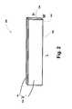
- FIG. 9shows a side view of an electro-mechanical transducer shown in FIG. 8 in a rest position.
- FIG. 10illustrates the electro-mechanical transducer according to the embodiment depicted in FIG. 8 operating in a first resonant mode.
- FIG. 11illustrates the electro-mechanical transducer according to the embodiment depicted in FIG. 8 operating in a second resonant mode.
- FIG. 12illustrates the electro-mechanical transducer according to the embodiment depicted in FIG. 8 operating in a third resonant mode.
- FIG. 13is a flow chart illustrating a method for producing an operational mode of an electro-mechanical transducer according to an embodiment.
- An apparatuscomprises a signal source, a driver and an electro-mechanical transducer having a cantilever.
- the signal sourceis configured to output a haptic feedback signal.
- the driveris configured to receive the haptic feedback signal and output a drive signal.
- the electro-mechanical transducerhas a cantilever and is configured to receive the drive signal.
- the electro-mechanical transduceris configured to have a set of operational modes. Each operational mode from the set of operational modes has at least one resonant mode from a set of resonant modes.
- electro-mechanical devicesare used in an electro-mechanical transducer that is configured to output haptic feedback in an operational mode having one or more resonant modes.
- the electro-mechanical transduceris also configured to have multiple operational modes.
- Such a devicecan produce diverse and robust haptic feedback that can exhibit relatively low power consumption in a space-efficient manner.
- cantileversas resonant structures
- analogous devicesare also possible.
- such resonant structurescan use acoustic cavities, membranes, mass-springs, wheel-torsional springs, and/or other structures capable of exhibiting mechanical resonance.
- Some embodiment, for example,can have a combination of different types of structure capable of exhibiting mechanical resonance.
- the term “operational mode”means a method or manner of functioning in a particular condition at a given time. For example, if a first electro-mechanical device is operating in a first resonant mode and a second electro-mechanical device is operating in a second resonant mode, the electro-mechanical transducer is operating collectively in, for example, a first operational mode. Alternatively, for example, if the first electro-mechanical device is operating in a third resonant mode, and the second electro-mechanical device is operating in a fourth resonant mode, the electro-mechanical transducer is operating collectively in a second operational mode.
- a given operation modecan be based on one electro-mechanical device operating in a resonant mode and another electro-mechanical device not being activated.
- resonant modemeans any mode of an electro-mechanical device operating in a frequency band centered around a resonant frequency.
- an electro-mechanical deviceoperates at or near a resonant frequency
- several consequencesoccur. For example, when a transducer operates at or near a resonant frequency, the inertial term and the elastic terms substantially cancel.
- the power consumed by the actuatoris then dedicated to balance dissipation (e.g. damping). If the dissipation is low, for example, in a cantilevered piezo-electric beam (i.e. a resonator with a high Q factor), the displacement is relatively large and limited by dissipative forces.
- the structurevibrates with a relatively large magnitude. Power lost during activation is in the dissipation. The remaining power is transmitted to the anatomy of the person with which the device is in contact.
- electro-mechanical devicemeans an individual active component configured to provide haptic feedback.
- active componentrefers to a single component that provides a mechanical response to the application of an electrical signal.
- a single length of, for example, piezoelectric materialfor example, piezoelectric bar 410
- the associated massfor example, mass 412
- the electro-mechanical transducerincludes only one electro-mechanical device.
- electro-mechanical transducermeans an apparatus having one or more electro-mechanical devices coupled to a mechanical ground.
- the electro-mechanical transducerincludes all three lengths of piezoelectric material, each having a mass coupled thereto.
- the electro-mechanical transducerincludes piezoelectric bar 610 and the masses 620 , 630 , and 640 .
- An embodiment of an electro-mechanical transduceris illustrated in FIG. 1 .
- An electro-mechanical transducer according to this embodimentincludes a drive circuit 110 having an amplifier and includes an electro-mechanical transducer 120 .
- the electro-mechanical transducer 120includes one or more electro-mechanical (E-M) devices 121 .
- Drive 110receives a haptic feedback signal and outputs a drive signal to electro-mechanical transducer 120 .
- the haptic feedback signalmay be based on a command from a microprocessor within, for example, a computer or a portable communications device (not shown).
- the electro-mechanical transducer 120is configured to selectively operate in one of multiple possible operational modes at a given time.
- the operational mode of the electro-mechanical transducer 120 at a given timewill depend, for example, on the characteristics of the drive signal received from driver 10 .
- an electro-mechanical transducercan operate in multiple resonant modes as will be described in greater detail below.
- the one or more electro-mechanical devices 121 of electro-mechanical transducer 120collectively output haptic feedback based on the drive signal, as illustrated in FIG. 7 .
- FIG. 2illustrates a piezoelectric bar in accordance with one embodiment. As described below in more detail, such a piezoelectric bar can be used as an electro-mechanical device within an electro-mechanical transducer.
- the piezoelectric bar 200is a bimorph piezoelectric device that is a two-layer bending motor having a length (L) 220 substantially larger than a width (W) 210 .
- the piezoelectric bar 200has a width (W) 210 of approximately 0.6 mm, a length (L) 220 of approximately 25 mm and a height (H) 230 of approximately 5 mm.
- the piezoelectric barcan have any suitable dimensions depending on the desired use.
- a voltage 240 from, for example, a drive source (not shown)is applied across the piezoelectric bar 200 , the piezoelectric bar 200 will flex.
- An appropriate level of voltage 240 to be applied to the piezoelectric bar 200can be selected, based at least in part, on the material and the thickness of the material used to construct the piezoelectric bar 200 .
- the piezoelectric bar 200can be driven near a resonant frequency.
- impedance transformationmay be obtained. Impedance transformation results in large mechanical displacements as described above.
- FIG. 3An electro-mechanical device 300 that can be used in combination with other electro-mechanical devices to construct an electro-mechanical transducer is illustrated as FIG. 3 .
- Multiple electro-mechanical devices 300can be configured to operate in a selected operational mode from a set of possible operational modes, each operational mode having one or more resonant modes, as will be described in further detail with respect to FIG. 5 .
- the electro-mechanical device 300 illustrated in FIG. 3includes a piezoelectric bar 310 having mass 320 coupled to an end portion 325 of the piezoelectric bar 310 .
- a second end portion 335 of the piezoelectric bar 310is coupled to a base member 330 .
- Base member 330acts as a mechanical ground and is configured to remain stationary relative to the movement of the piezoelectric bar 310 .
- the electro-mechanical device illustrated in FIG. 3can operate as follows.
- a voltage 340 from a voltage source (not shown)can be applied to piezoelectric bar 310 .
- the piezoelectric barcan be, for example, a bimorph piezoelectric device as described above in connection with FIG. 2 .
- Voltage 340causes piezoelectric bar 310 to flex in a first direction D 1 .
- Voltage 340can be modulated at a frequency, f d , which is referred to herein as the drive frequency of the electro-mechanical device 300 .
- the frequency f dcan be selected such that the electro-mechanical device 300 operates near a resonant frequency the electro-mechanical device 300 .
- Frequency f dis a function of the type of electro-mechanical device used in the electro-mechanical transducer, the dimensions of the electro-mechanical device (e.g., the length, width, height or thickness), and the position and weight of the masses in the electro-mechanical device.
- the electro-mechanical device 300can produce a large vibration sensation relative to the voltage 340 applied to the electro-mechanical device 300 .
- Both the weight of mass 320 and the length of the piezoelectric bar 310affect the amplitude of the displacement. Furthermore, the weight of mass 320 and the length of the piezoelectric bar 310 affect the resonant frequencies of the electro-mechanical device 300 . Therefore, the particular resonant frequencies may be tailored by selecting the appropriate length of the piezoelectric bar and/or weight of the mass 320 for a desired resonant frequency.
- voltage 340is applied to the piezoelectric bar 310 , the electro-mechanical device 300 will move in a plane oriented as vertical for the depiction in FIG. 3 .
- FIG. 4shows an electro-mechanical device 350 including a piezoelectric bar 360 having mass 370 coupled to an end portion 375 of piezoelectric bar 360 .
- the piezoelectric bar 360has its second end portion 385 coupled to a base member 380 , which acts as a ground and is configured to remain stationary with respect to movement of the piezoelectric bar 360 .
- the operation of the electro-mechanical device 350is similar to the embodiment described with reference to FIG. 3 except that when voltage 390 is applied to piezoelectric bar 360 , the electro-mechanical device 350 will vibrate in direction D 2 (i.e., relative to the perspective shown in FIG. 4 ) due to the orientation of the bimorph piezoelectric bar 360 relative to base member 380 .
- FIG. 5illustrates an electro-mechanical transducer 400 , according to another embodiment.
- the electro-mechanical transducer 400includes three electro-mechanical devices 410 , 420 , and 430 .
- each of the electro-mechanical devices 410 , 420 and 430includes a piezoelectric bar 411 , 421 , and 431 , respectively.
- a mass 412 , 422 , and 432can be coupled to an end portion 413 , 423 , or 433 , of each piezoelectric bar 411 , 421 and 431 , respectively.
- each piezoelectric bar 411 , 421 , and 431is coupled to a base member 440 .
- Base member 440can be configured to remain stationary with respect to movement of the piezoelectric bars 411 , 421 and 431 . More specifically, base member 440 is stationary relative to any movement of piezoelectric bars 411 , 421 and 431 , but can move in the context of the overall product or device (e.g., mobile phone, game controller, etc.) with which the electro-mechanical device 400 is disposed. In fact, base member 440 can relay the vibrations produced by the movement of piezoelectric bars 411 , 421 and 431 to the product or device.
- Base member 440may be a single contiguous mechanical ground, as illustrated in FIG. 5 . Alternatively, each piezoelectric bar 411 , 421 , and 431 may be coupled to a different mechanical ground.
- Piezoelectric bars 411 , 421 , and 431have lengths L 1 , L 2 , and L 3 , respectively. In one embodiment, these lengths may be the same. Alternatively, lengths L 1 , L 2 , and L 3 can be different. Additionally, the weights of masses 412 , 422 , and 432 , can be equal to one another. Alternatively, weights of the masses 412 , 422 , and 432 can be different from one another. The particular configuration of the masses 412 , 422 and 432 and the lengths of the piezoelectric bars 411 , 421 , and 431 can be based on the desired frequency response from the electro-mechanical transducer 400 .
- Voltage 450can be applied to the electro-mechanical devices through contacts 451 .
- the voltagemay by modulated at approximately the resonant frequency of the electro-mechanical devices 410 , 420 , and/or 430 .
- the voltagemay be applied by a single voltage source via contacts 451 , or alternatively, each electro-mechanical device 410 , 420 , 430 , may have an independent voltage source (not shown) that is modulated approximately at the resonant frequency of the respective electro-mechanical device, or a resonant mode of the respective electro-mechanical device.
- voltage 450may be modulated at a higher order resonant frequency of the electro-mechanical devices 410 , 420 , and/or 430 .
- the electro-mechanical transducer 400can include electro-mechanical devices 410 , 420 , and 430 that have different lengths L 1 , L 2 , L 3 .
- each of the electro-mechanical devices 410 , 420 , and 430has a different resonant frequency f 1 , f 2 and f 3 , respectively.
- These different resonant frequenciescan be driven at different drive frequencies f 1 , f 2 and f 3 .
- FIG. 7An example of the frequency response for an electro-mechanical transducer 400 is illustrated in FIG. 7 . As depicted in the plot in FIG.
- an electro-mechanical transducer with three electro-mechanical devices each operating at a different resonant frequency (or resonants thereof)has a frequency response with a greater bandwidth than the frequency response for an electro-mechanical transducer having a single electro-mechanical device, which is illustrated in FIG. 7 .
- the gain values shown on the y-axes in FIGS. 6 and 7relate to the magnitude of the device position divided by the magnitude of the input voltage to the device.
- masses 412 , 422 , and 432 and lengths L 1 , L 2 , and L 3 of electro-mechanical devices 411 , 421 , and 431can be configured such that a single drive frequency, f d , may be used to drive, for example, the resonant mode in electro-mechanical device 411 , the first resonant mode in electro-mechanical device 422 , and the second resonant mode in electro-mechanical device 432 .
- the bandwidth of the electro-mechanical transducer 400may be adjusted by selectively operating one or more of the electro-mechanical devices 410 , 420 , 430 in different resonant modes. Each one of these combinations of resonant frequencies collectively superpose into a different operational mode of the electro-mechanical transducer 400 .
- the electro-mechanical transducer 400can be operated such that electro-mechanical devices 410 and 430 may be operating at frequencies f, and f 3 , respectively, with f 1 and f 3 being resonant modes of the electro-mechanical devices 410 and 430 , respectively.
- a voltageneed not be applied to electro-mechanical device 420 in this operational mode.
- the output of the electro-mechanical transducer 400would include peaks 510 and 530 illustrated in FIG. 7 .
- the electro-mechanical transducer 400can be operated such that electro-mechanical devices 410 and 420 are operating at frequencies f 1 and f 2 , respectively, where f 1 and f 2 are resonant modes of the electro-mechanical devices 410 and 420 .
- the electro-mechanical transducer 400can produce an output having only two peaks, as illustrated, for example, in FIG. 7 as 510 and 520 .
- This operational modecan have two frequencies that are different from the two frequencies of the first operational mode described above. Therefore, by changing the operational mode of the electro-mechanical transducer 400 , the resultant frequencies of the tactile feedback can be changed.
- the electro-mechanical transducer 400can be operated such that electro-mechanical devices 420 and 430 may be operating at frequencies f 2 and f 3 , respectively, where f 2 and f 3 are resonant modes of each of the electro-mechanical devices 420 and 430 .
- the electro-mechanical transducer 400can produce an output having only two peaks, as illustrated, for example, in FIG. 7 as 520 and 530 .
- This operational modecan have two frequencies that are different from the two frequencies for first operational mode described above.
- the third operational modecan have two frequencies that are different from the two frequencies of the second operational mode. Therefore, by changing the operational mode of the electro-mechanical transducer 400 , the resultant frequencies of the haptic feedback can be changed.
- the electro-mechanical transducer 400can be operated such that one of electro-mechanical devices 410 , 420 and 430 is operating at frequencies f 1 , f 2 and f 3 , respectively, where f 1 , f 2 and f 3 are resonant modes of each of the electro-mechanical devices 410 , 420 and 430 .
- the electro-mechanical transducer 400can produce an output having only one peak at a time. In other words, operational modes are possible where only a single electro-mechanical device is actuated at a given time.
- the voltagecan be modulated at a number of different drive frequencies, f d .
- the drive frequency f dcan approximate a resonant mode of the electro-mechanical devices.
- f dcan include any other frequency that is an integral multiple of the electro-mechanical device's resonant frequency.
- electro-mechanical devicesthat included piezoelectric bars
- any electro-active material or devicecan be used.
- the electro-mechanical devicescan include electro-active polymers (EAP), voice coil transducers or other electromagnetic device, an inertial resonant device, or a resonant eccentric rotating mass (HERM) device.
- EAPelectro-active polymers
- HERMresonant eccentric rotating mass
- An example of an inertial resonant deviceis described in U.S. Pat. No. 6,088,019.
- An example of a HERM deviceis described in U.S. Pat. No. 7,161,580.
- FIG. 8illustrates an alternative embodiment of an electro-mechanical transducer 600 having multiple masses 620 , 630 , and 640 disposed on the same piezoelectric bar 610 .
- electro-mechanical transducer 600comprises one electro-mechanical device, the structure of which corresponds to the structure of electro-mechanical transducer 600 .
- the piezoelectric bar 610is secured to a base member 650 , which acts as a mechanical ground and remains substantially fixed with respect to the movement of the electro-mechanical device 600 .
- Masses 620 , 630 , and 640can have equal weights or can have different weights. Alternatively, the weights of the two masses can be equal to one another, while the weight of the third mass can be different. Additionally, the masses 620 , 630 , and 640 can be equally spaced along the length of the piezoelectric bar 610 or can be spaced at any desired location along the length of the piezoelectric bar 610 .
- the weight of and spacing between masses 620 , 630 , and 640allow the electro-mechanical device to be designed to have a predetermined number of resonant frequencies.
- FIGS. 7-10illustrate an example of the different operational modes that can be obtained with an electro-mechanical transducer 600 bearing three masses.
- the bends in the piezoelectric bar 610are exaggerated in this figure to illustrate the bending of the piezoelectric bar 610 more clearly.
- Frequency modulated voltagecan be applied to the piezoelectric bar 610 .
- the electro-mechanical deviceis initially in a resting position.
- FIG. 10illustrates a first resonant mode of the electro-mechanical device.
- FIG. 11illustrates a second resonant mode of the electro-mechanical device.
- FIG. 12illustrates a third resonant mode of the electro-mechanical device.
- the modes illustrated in FIGS. 7-10will produce a resultant output having frequencies that are similar to the frequencies illustrated in FIG. 7 due to the superposition of the three resonant modes produced by the electro-mechanical device.
- FIG. 13illustrates a method for producing an operational mode of an electro-mechanical transducer, according to an embodiment.
- a haptic feedback signalis generated.
- the haptic feedback signalis supplied to a driver.
- the drive signalis then applied to a first electro-mechanical device.
- a drive signalis also applied to the second electro-mechanical device.
- the electro-mechanical devicesoutput haptic feedback that includes haptic feedback at a first resonant mode (step 1151 ) and haptic feedback at a second resonant mode (step 1152 ).
- the output of haptic feedback at a first resonant mode by a first electro-mechanical device and/or at a second resonant mode by a second electro-mechanical devicecorrespond to an operational mode of the electro-mechanical transducer having the first electro-mechanical device and/or the second electro-mechanical device, respectively.
- electro-mechanical devicescan be added and can have the drive signal selectively applied thereto to collectively yield a variety of different operational modes of the electro-mechanical transducer.
- the electro-mechanical transducermay include multiple masses, as illustrated in FIG. 8 .
- the electro-mechanical transducercan output haptic feedback having multiple frequencies for a given operational mode.
- a number of electro-mechanical devices in a serial configurationcan be arranged in parallel as illustrated in FIG. 5 .
- electro-mechanical transducerscan be used in cellular phones, electronic pagers, laptop touch pads, a cordless mouse or other computer peripherals whether cordless or otherwise, a personal digital assistant (PDA), along with a variety of other portable and non-portable devices.
- PDApersonal digital assistant
- the piezoelectric devicecan have a planar shape where the width is approximately the same as the length.
- electro-mechanical devicesmay include electro-active polymers (EAP), voice coil transducers or other electromagnetic device, or resonant eccentric rotating mass (HERM) devices.
- EAPelectro-active polymers
- HERMresonant eccentric rotating mass
Landscapes
- Engineering & Computer Science (AREA)
- General Engineering & Computer Science (AREA)
- Theoretical Computer Science (AREA)
- Mechanical Engineering (AREA)
- Human Computer Interaction (AREA)
- Physics & Mathematics (AREA)
- General Physics & Mathematics (AREA)
- Apparatuses For Generation Of Mechanical Vibrations (AREA)
- User Interface Of Digital Computer (AREA)
- Separation Using Semi-Permeable Membranes (AREA)
Abstract
Description
Claims (20)
Priority Applications (1)
| Application Number | Priority Date | Filing Date | Title |
|---|---|---|---|
| US12/075,933US8576174B2 (en) | 2002-04-25 | 2008-03-14 | Haptic devices having multiple operational modes including at least one resonant mode |
Applications Claiming Priority (4)
| Application Number | Priority Date | Filing Date | Title |
|---|---|---|---|
| US37593002P | 2002-04-25 | 2002-04-25 | |
| US10/301,809US7161580B2 (en) | 2002-04-25 | 2002-11-22 | Haptic feedback using rotary harmonic moving mass |
| US10/792,279US7369115B2 (en) | 2002-04-25 | 2004-03-04 | Haptic devices having multiple operational modes including at least one resonant mode |
| US12/075,933US8576174B2 (en) | 2002-04-25 | 2008-03-14 | Haptic devices having multiple operational modes including at least one resonant mode |
Related Parent Applications (1)
| Application Number | Title | Priority Date | Filing Date |
|---|---|---|---|
| US10/792,279ContinuationUS7369115B2 (en) | 2002-04-25 | 2004-03-04 | Haptic devices having multiple operational modes including at least one resonant mode |
Publications (2)
| Publication Number | Publication Date |
|---|---|
| US20080170037A1 US20080170037A1 (en) | 2008-07-17 |
| US8576174B2true US8576174B2 (en) | 2013-11-05 |
Family
ID=34961337
Family Applications (2)
| Application Number | Title | Priority Date | Filing Date |
|---|---|---|---|
| US10/792,279Expired - Fee RelatedUS7369115B2 (en) | 2002-04-25 | 2004-03-04 | Haptic devices having multiple operational modes including at least one resonant mode |
| US12/075,933Expired - Fee RelatedUS8576174B2 (en) | 2002-04-25 | 2008-03-14 | Haptic devices having multiple operational modes including at least one resonant mode |
Family Applications Before (1)
| Application Number | Title | Priority Date | Filing Date |
|---|---|---|---|
| US10/792,279Expired - Fee RelatedUS7369115B2 (en) | 2002-04-25 | 2004-03-04 | Haptic devices having multiple operational modes including at least one resonant mode |
Country Status (3)
| Country | Link |
|---|---|
| US (2) | US7369115B2 (en) |
| GB (1) | GB2427014B (en) |
| WO (1) | WO2005087392A1 (en) |
Cited By (4)
| Publication number | Priority date | Publication date | Assignee | Title |
|---|---|---|---|---|
| US20160259415A1 (en)* | 2007-06-26 | 2016-09-08 | Immersion Corporation | Methods and Apparatus for Multi-Touch Tactile Touch Panel Actuator Mechanisms |
| US10371544B2 (en) | 2017-05-04 | 2019-08-06 | Wearworks | Vibrating haptic device for the blind |
| US10613629B2 (en) | 2015-03-27 | 2020-04-07 | Chad Laurendeau | System and method for force feedback interface devices |
| US11399534B2 (en)* | 2015-11-03 | 2022-08-02 | Nrg Systems, Inc. | Techniques for providing a broad-band ultrasonic transducer device using a plurality of narrow-band transducer arrays and a method of wildlife deterrence using same |
Families Citing this family (93)
| Publication number | Priority date | Publication date | Assignee | Title |
|---|---|---|---|---|
| US6429846B2 (en) | 1998-06-23 | 2002-08-06 | Immersion Corporation | Haptic feedback for touchpads and other touch controls |
| US6822635B2 (en) | 2000-01-19 | 2004-11-23 | Immersion Corporation | Haptic interface for laptop computers and other portable devices |
| US7084854B1 (en)* | 2000-09-28 | 2006-08-01 | Immersion Corporation | Actuator for providing tactile sensations and device for directional tactile sensations |
| AU2003298038A1 (en) | 2002-12-08 | 2004-06-30 | Immersion Corporation | Using haptic effects to enhance information content in communications |
| US8830161B2 (en)* | 2002-12-08 | 2014-09-09 | Immersion Corporation | Methods and systems for providing a virtual touch haptic effect to handheld communication devices |
| US8059088B2 (en) | 2002-12-08 | 2011-11-15 | Immersion Corporation | Methods and systems for providing haptic messaging to handheld communication devices |
| US20060136630A1 (en)* | 2002-12-08 | 2006-06-22 | Immersion Corporation, A Delaware Corporation | Methods and systems for providing haptic messaging to handheld communication devices |
| US20060136631A1 (en)* | 2002-12-08 | 2006-06-22 | Immersion Corporation, A Delaware Corporation | Methods and systems for providing haptic messaging to handheld communication devices |
| US7779166B2 (en)* | 2002-12-08 | 2010-08-17 | Immersion Corporation | Using haptic effects to enhance information content in communications |
| US20060066569A1 (en)* | 2003-12-08 | 2006-03-30 | Immersion Corporation, A Delaware Corporation | Methods and systems for providing haptic messaging to handheld communication devices |
| JP4046095B2 (en)* | 2004-03-26 | 2008-02-13 | ソニー株式会社 | Input device with tactile function, information input method, and electronic device |
| US8232969B2 (en)* | 2004-10-08 | 2012-07-31 | Immersion Corporation | Haptic feedback for button and scrolling action simulation in touch input devices |
| US20100312129A1 (en) | 2005-01-26 | 2010-12-09 | Schecter Stuart O | Cardiovascular haptic handle system |
| US7825903B2 (en)* | 2005-05-12 | 2010-11-02 | Immersion Corporation | Method and apparatus for providing haptic effects to a touch panel |
| WO2007030603A2 (en) | 2005-09-08 | 2007-03-15 | Wms Gaming Inc. | Gaming machine having display with sensory feedback |
| DE102005060779B4 (en)* | 2005-12-16 | 2008-07-10 | Eads Deutschland Gmbh | power generator |
| US8525778B2 (en) | 2007-03-21 | 2013-09-03 | Northwestern University | Haptic device with controlled traction forces |
| US8210942B2 (en)* | 2006-03-31 | 2012-07-03 | Wms Gaming Inc. | Portable wagering game with vibrational cues and feedback mechanism |
| DE102006053422A1 (en)* | 2006-11-13 | 2008-05-15 | Epcos Ag | vibration system |
| DE102006053421A1 (en)* | 2006-11-13 | 2008-05-15 | Epcos Ag | vibration generator |
| US8395587B2 (en)* | 2007-12-21 | 2013-03-12 | Motorola Mobility Llc | Haptic response apparatus for an electronic device |
| US8553005B2 (en) | 2008-01-04 | 2013-10-08 | Tactus Technology, Inc. | User interface system |
| US9588683B2 (en) | 2008-01-04 | 2017-03-07 | Tactus Technology, Inc. | Dynamic tactile interface |
| US8704790B2 (en) | 2010-10-20 | 2014-04-22 | Tactus Technology, Inc. | User interface system |
| US8922510B2 (en) | 2008-01-04 | 2014-12-30 | Tactus Technology, Inc. | User interface system |
| US8547339B2 (en) | 2008-01-04 | 2013-10-01 | Tactus Technology, Inc. | System and methods for raised touch screens |
| US9552065B2 (en) | 2008-01-04 | 2017-01-24 | Tactus Technology, Inc. | Dynamic tactile interface |
| US9430074B2 (en) | 2008-01-04 | 2016-08-30 | Tactus Technology, Inc. | Dynamic tactile interface |
| US8179377B2 (en)* | 2009-01-05 | 2012-05-15 | Tactus Technology | User interface system |
| US9557915B2 (en) | 2008-01-04 | 2017-01-31 | Tactus Technology, Inc. | Dynamic tactile interface |
| US9274612B2 (en) | 2008-01-04 | 2016-03-01 | Tactus Technology, Inc. | User interface system |
| US8154527B2 (en) | 2008-01-04 | 2012-04-10 | Tactus Technology | User interface system |
| US8456438B2 (en) | 2008-01-04 | 2013-06-04 | Tactus Technology, Inc. | User interface system |
| US8947383B2 (en) | 2008-01-04 | 2015-02-03 | Tactus Technology, Inc. | User interface system and method |
| US9052790B2 (en) | 2008-01-04 | 2015-06-09 | Tactus Technology, Inc. | User interface and methods |
| US8243038B2 (en) | 2009-07-03 | 2012-08-14 | Tactus Technologies | Method for adjusting the user interface of a device |
| US20160187981A1 (en) | 2008-01-04 | 2016-06-30 | Tactus Technology, Inc. | Manual fluid actuator |
| US9423875B2 (en) | 2008-01-04 | 2016-08-23 | Tactus Technology, Inc. | Dynamic tactile interface with exhibiting optical dispersion characteristics |
| US9720501B2 (en) | 2008-01-04 | 2017-08-01 | Tactus Technology, Inc. | Dynamic tactile interface |
| US9063627B2 (en) | 2008-01-04 | 2015-06-23 | Tactus Technology, Inc. | User interface and methods |
| US9298261B2 (en) | 2008-01-04 | 2016-03-29 | Tactus Technology, Inc. | Method for actuating a tactile interface layer |
| US9612659B2 (en) | 2008-01-04 | 2017-04-04 | Tactus Technology, Inc. | User interface system |
| US8570295B2 (en) | 2008-01-04 | 2013-10-29 | Tactus Technology, Inc. | User interface system |
| US8179375B2 (en)* | 2008-01-04 | 2012-05-15 | Tactus Technology | User interface system and method |
| JP5130422B2 (en)* | 2008-11-07 | 2013-01-30 | 独立行政法人産業技術総合研究所 | Detection sensor |
| GB2462465B (en)* | 2008-08-08 | 2013-02-13 | Hiwave Technologies Uk Ltd | Touch sensitive device |
| US8686952B2 (en) | 2008-12-23 | 2014-04-01 | Apple Inc. | Multi touch with multi haptics |
| JP2010157037A (en)* | 2008-12-26 | 2010-07-15 | Nissha Printing Co Ltd | Panel member having oscillating element |
| WO2010078596A1 (en) | 2009-01-05 | 2010-07-08 | Tactus Technology, Inc. | User interface system |
| US9588684B2 (en) | 2009-01-05 | 2017-03-07 | Tactus Technology, Inc. | Tactile interface for a computing device |
| KR101615872B1 (en)* | 2009-05-08 | 2016-04-27 | 삼성전자주식회사 | A method for transmitting haptic function in mobile terminal and system thereof |
| WO2011003113A1 (en) | 2009-07-03 | 2011-01-06 | Tactus Technology | User interface enhancement system |
| GB2474047B (en)* | 2009-10-02 | 2014-12-17 | New Transducers Ltd | Touch sensitive device |
| US8610549B2 (en) | 2009-10-16 | 2013-12-17 | Immersion Corporation | Systems and methods for providing haptic feedback at multiple resonance frequencies |
| US8542105B2 (en) | 2009-11-24 | 2013-09-24 | Immersion Corporation | Handheld computer interface with haptic feedback |
| WO2011087816A1 (en) | 2009-12-21 | 2011-07-21 | Tactus Technology | User interface system |
| CN102782617B (en) | 2009-12-21 | 2015-10-07 | 泰克图斯科技公司 | User interface system |
| US9298262B2 (en) | 2010-01-05 | 2016-03-29 | Tactus Technology, Inc. | Dynamic tactile interface |
| US20110260988A1 (en)* | 2010-01-20 | 2011-10-27 | Northwestern University | Method and apparatus for increasing magnitude and frequency of forces applied to a bare finger on a haptic surface |
| US8619035B2 (en)* | 2010-02-10 | 2013-12-31 | Tactus Technology, Inc. | Method for assisting user input to a device |
| WO2011112984A1 (en) | 2010-03-11 | 2011-09-15 | Tactus Technology | User interface system |
| WO2011133605A1 (en) | 2010-04-19 | 2011-10-27 | Tactus Technology | Method of actuating a tactile interface layer |
| WO2011133604A1 (en) | 2010-04-19 | 2011-10-27 | Tactus Technology | User interface system |
| US8416066B2 (en) | 2010-04-29 | 2013-04-09 | Microsoft Corporation | Active vibrations |
| US10645834B2 (en)* | 2010-08-23 | 2020-05-05 | Nokia Technologies Oy | Apparatus and method for providing haptic and audio feedback in a touch sensitive user interface |
| EP2609338A4 (en)* | 2010-08-25 | 2017-02-15 | Aavid Thermalloy, LLC | Cantilever fan |
| CN103124946B (en) | 2010-10-20 | 2016-06-29 | 泰克图斯科技公司 | User interface system and method |
| US8942828B1 (en) | 2011-04-13 | 2015-01-27 | Stuart Schecter, LLC | Minimally invasive cardiovascular support system with true haptic coupling |
| US20120302323A1 (en) | 2011-05-23 | 2012-11-29 | Wms Gaming Inc. | Haptic gaming chairs and wagering game systems and machines with a haptic gaming chair |
| US10180722B2 (en) | 2011-05-27 | 2019-01-15 | Honeywell International Inc. | Aircraft user interfaces with multi-mode haptics |
| US9142083B2 (en) | 2011-06-13 | 2015-09-22 | Bally Gaming, Inc. | Convertible gaming chairs and wagering game systems and machines with a convertible gaming chair |
| WO2012177719A2 (en) | 2011-06-21 | 2012-12-27 | Northwestern University | Touch interface device and method for applying lateral forces on a human appendage |
| US10013082B2 (en) | 2012-06-05 | 2018-07-03 | Stuart Schecter, LLC | Operating system with haptic interface for minimally invasive, hand-held surgical instrument |
| WO2014047656A2 (en) | 2012-09-24 | 2014-03-27 | Tactus Technology, Inc. | Dynamic tactile interface and methods |
| US9405417B2 (en) | 2012-09-24 | 2016-08-02 | Tactus Technology, Inc. | Dynamic tactile interface and methods |
| US9196134B2 (en)* | 2012-10-31 | 2015-11-24 | Immersion Corporation | Method and apparatus for simulating surface features on a user interface with haptic effects |
| JP6498863B2 (en)* | 2012-12-13 | 2019-04-10 | イマージョン コーポレーションImmersion Corporation | Haptic system with increased LRA bandwidth |
| US9557813B2 (en) | 2013-06-28 | 2017-01-31 | Tactus Technology, Inc. | Method for reducing perceived optical distortion |
| US9213408B2 (en) | 2013-10-08 | 2015-12-15 | Immersion Corporation | Generating haptic effects while minimizing cascading |
| US9836123B2 (en) | 2014-02-13 | 2017-12-05 | Mide Technology Corporation | Bussed haptic actuator system and method |
| US9542801B1 (en) | 2014-04-28 | 2017-01-10 | Bally Gaming, Inc. | Wearable wagering game system and methods |
| US9858751B2 (en) | 2014-09-26 | 2018-01-02 | Bally Gaming, Inc. | Wagering game wearables |
| JP6593761B2 (en)* | 2014-11-19 | 2019-10-23 | パナソニックIpマネジメント株式会社 | Input / output operation device |
| CN104732876B (en)* | 2014-12-15 | 2017-10-24 | 深圳清华大学研究院 | The mark system and its marker of a kind of audio resonance |
| CN104703104A (en)* | 2015-03-31 | 2015-06-10 | 歌尔声学股份有限公司 | Combined structure of piezoelectric receiver and ultrasonic generator |
| US10256749B2 (en)* | 2015-07-02 | 2019-04-09 | Seiko Epson Corporation | Piezoelectric actuator, motor, robot, and method of driving piezoelectric actuator |
| US10120448B2 (en)* | 2015-08-06 | 2018-11-06 | Apple Inc. | Method of tuning a haptic actuator including ferromagnetic mass change iterations and related apparatus |
| DE102016116760B4 (en) | 2016-09-07 | 2018-10-18 | Epcos Ag | Device for generating a haptic feedback and electronic device |
| KR102384033B1 (en) | 2017-03-20 | 2022-04-06 | 엘지전자 주식회사 | Display Apparatus |
| CN107147332A (en)* | 2017-07-17 | 2017-09-08 | 山东大学 | Low-frequency broadband vibration energy harvester and method of piezoelectric beam-lumped mass interphase structure |
| US10477321B2 (en) | 2018-03-05 | 2019-11-12 | Google Llc | Driving distributed mode loudspeaker actuator that includes patterned electrodes |
| US10579146B2 (en) | 2018-06-15 | 2020-03-03 | Immersion Corporation | Systems and methods for multi-level closed loop control of haptic effects |
| US10747321B2 (en) | 2018-06-15 | 2020-08-18 | Immersion Corporation | Systems and methods for differential optical position sensing for haptic actuation |
Citations (188)
| Publication number | Priority date | Publication date | Assignee | Title |
|---|---|---|---|---|
| US2972140A (en) | 1958-09-23 | 1961-02-14 | Hirsch Joseph | Apparatus and method for communication through the sense of touch |
| US3157853A (en) | 1957-12-06 | 1964-11-17 | Hirsch Joseph | Tactile communication system |
| US3220121A (en) | 1962-07-08 | 1965-11-30 | Communications Patents Ltd | Ground-based flight training or simulating apparatus |
| US3497668A (en) | 1966-08-25 | 1970-02-24 | Joseph Hirsch | Tactile control system |
| US3517446A (en) | 1967-04-19 | 1970-06-30 | Singer General Precision | Vehicle trainer controls and control loading |
| US3623064A (en) | 1968-10-11 | 1971-11-23 | Bell & Howell Co | Paging receiver having cycling eccentric mass |
| US3902687A (en) | 1973-06-25 | 1975-09-02 | Robert E Hightower | Aircraft indicator system |
| US3903614A (en) | 1970-03-27 | 1975-09-09 | Singer Co | Apparatus for simulating aircraft control loading |
| US3911416A (en) | 1974-08-05 | 1975-10-07 | Motorola Inc | Silent call pager |
| US3919691A (en) | 1971-05-26 | 1975-11-11 | Bell Telephone Labor Inc | Tactile man-machine communication system |
| US4127752A (en) | 1977-10-13 | 1978-11-28 | Sheldahl, Inc. | Tactile touch switch panel |
| US4160508A (en) | 1977-08-19 | 1979-07-10 | Nasa | Controller arm for a remotely related slave arm |
| US4236325A (en) | 1978-12-26 | 1980-12-02 | The Singer Company | Simulator control loading inertia compensator |
| US4262240A (en) | 1978-03-02 | 1981-04-14 | Ricoh Company, Ltd. | Stepping motor apparatus comprising electrical detent means |
| US4262549A (en) | 1978-05-10 | 1981-04-21 | Schwellenbach Donald D | Variable mechanical vibrator |
| US4333070A (en) | 1981-02-06 | 1982-06-01 | Barnes Robert W | Motor vehicle fuel-waste indicator |
| US4334280A (en) | 1980-06-09 | 1982-06-08 | Texas Instruments Incorporated | System and method for providing an audible sound and a tactile feedback in an electronic data processing system |
| US4355348A (en) | 1980-07-30 | 1982-10-19 | Williams Theodore R | Audio signal responsive optical display |
| US4382166A (en) | 1981-12-03 | 1983-05-03 | Wico Corporation | Joystick with built-in fire button |
| US4414984A (en) | 1977-12-19 | 1983-11-15 | Alain Zarudiansky | Methods and apparatus for recording and or reproducing tactile sensations |
| US4459440A (en) | 1983-03-21 | 1984-07-10 | Wico Corporation | Joystick and switch assembly therefor |
| US4464117A (en) | 1980-08-27 | 1984-08-07 | Dr. Ing. Reiner Foerst Gmbh | Driving simulator apparatus |
| US4473725A (en) | 1982-10-26 | 1984-09-25 | Wico Corporation | Modular joystick controller |
| US4484191A (en) | 1982-06-14 | 1984-11-20 | Vavra George S | Tactile signaling systems for aircraft |
| US4490841A (en) | 1981-10-21 | 1984-12-25 | Sound Attenuators Limited | Method and apparatus for cancelling vibrations |
| US4513235A (en) | 1982-01-22 | 1985-04-23 | British Aerospace Public Limited Company | Control apparatus |
| US4581491A (en) | 1984-05-04 | 1986-04-08 | Research Corporation | Wearable tactile sensory aid providing information on voice pitch and intonation patterns |
| US4599070A (en) | 1981-07-29 | 1986-07-08 | Control Interface Company Limited | Aircraft simulator and simulated control system therefor |
| US4600854A (en) | 1984-03-05 | 1986-07-15 | International Business Machines Corp. | Piezoelectric stepping rotator |
| US4706294A (en) | 1985-06-11 | 1987-11-10 | Alpine Electronics Inc. | Audio control device |
| US4708656A (en) | 1985-11-11 | 1987-11-24 | Fokker B.V. | Simulator of mechanical properties of a steering system |
| US4713007A (en) | 1985-10-11 | 1987-12-15 | Alban Eugene P | Aircraft controls simulator |
| US4731603A (en) | 1985-08-30 | 1988-03-15 | Unisys Corporation | Tactile alarm system for gaining the attention of an individual |
| US4768412A (en) | 1986-05-09 | 1988-09-06 | Sanderson Stephen N | Low profile keyboard device and system for recording and scoring music |
| US4794392A (en) | 1987-02-20 | 1988-12-27 | Motorola, Inc. | Vibrator alert device for a communication receiver |
| US4795296A (en) | 1986-11-17 | 1989-01-03 | California Institute Of Technology | Hand-held robot end effector controller having movement and force control |
| US4868549A (en) | 1987-05-18 | 1989-09-19 | International Business Machines Corporation | Feedback mouse |
| US4885565A (en) | 1988-06-01 | 1989-12-05 | General Motors Corporation | Touchscreen CRT with tactile feedback |
| US4891764A (en) | 1985-12-06 | 1990-01-02 | Tensor Development Inc. | Program controlled force measurement and control system |
| EP0349086A1 (en) | 1988-06-29 | 1990-01-03 | Stork Kwant B.V. | Control system |
| US4930770A (en) | 1988-12-01 | 1990-06-05 | Baker Norman A | Eccentrically loaded computerized positive/negative exercise machine |
| US4934694A (en) | 1985-12-06 | 1990-06-19 | Mcintosh James L | Computer controlled exercise system |
| US5019761A (en) | 1989-02-21 | 1991-05-28 | Kraft Brett W | Force feedback control for backhoe |
| US5022384A (en) | 1990-05-14 | 1991-06-11 | Capitol Systems | Vibrating/massage chair |
| US5022407A (en) | 1990-01-24 | 1991-06-11 | Topical Testing, Inc. | Apparatus for automated tactile testing |
| US5035242A (en) | 1990-04-16 | 1991-07-30 | David Franklin | Method and apparatus for sound responsive tactile stimulation of deaf individuals |
| US5038089A (en) | 1988-03-23 | 1991-08-06 | The United States Of America As Represented By The Administrator Of The National Aeronautics And Space Administration | Synchronized computational architecture for generalized bilateral control of robot arms |
| US5078152A (en) | 1985-06-23 | 1992-01-07 | Loredan Biomedical, Inc. | Method for diagnosis and/or training of proprioceptor feedback capabilities in a muscle and joint system of a human patient |
| WO1992000559A1 (en) | 1990-06-25 | 1992-01-09 | Hewlett-Packard Company | Input device with tactile feedback |
| US5103404A (en) | 1985-12-06 | 1992-04-07 | Tensor Development, Inc. | Feedback for a manipulator |
| US5107262A (en) | 1988-10-13 | 1992-04-21 | Ministere De La Culture, De La Communication, Des Grands Travaux Et Du Bicentenaire | Modular retroactive keyboard and a flat modular actuator |
| US5146566A (en) | 1991-05-29 | 1992-09-08 | Ibm Corporation | Input/output system for computer user interface using magnetic levitation |
| US5165897A (en) | 1990-08-10 | 1992-11-24 | Tini Alloy Company | Programmable tactile stimulator array system and method of operation |
| US5172092A (en) | 1990-04-26 | 1992-12-15 | Motorola, Inc. | Selective call receiver having audible and tactile alerts |
| US5175459A (en) | 1991-08-19 | 1992-12-29 | Motorola, Inc. | Low profile vibratory alerting device |
| US5184319A (en) | 1990-02-02 | 1993-02-02 | Kramer James F | Force feedback and textures simulating interface device |
| US5184310A (en) | 1989-03-31 | 1993-02-02 | Sharp Kabushiki Kaisha | Signal generation circuit |
| US5186629A (en) | 1991-08-22 | 1993-02-16 | International Business Machines Corporation | Virtual graphics display capable of presenting icons and windows to the blind computer user and method |
| US5186695A (en) | 1989-02-03 | 1993-02-16 | Loredan Biomedical, Inc. | Apparatus for controlled exercise and diagnosis of human performance |
| US5203563A (en) | 1991-03-21 | 1993-04-20 | Atari Games Corporation | Shaker control device |
| US5212473A (en) | 1991-02-21 | 1993-05-18 | Typeright Keyboard Corp. | Membrane keyboard and method of using same |
| US5227594A (en) | 1991-12-12 | 1993-07-13 | Guardian Electric Manufacturing Company | Electrical multi-directional switch |
| US5240417A (en) | 1991-03-14 | 1993-08-31 | Atari Games Corporation | System and method for bicycle riding simulation |
| US5245245A (en) | 1992-05-04 | 1993-09-14 | Motorola, Inc. | Mass-loaded cantilever vibrator |
| US5261291A (en) | 1992-08-17 | 1993-11-16 | Schoch Paul T | Ergonomic apparatus for controlling a vehicle |
| US5271290A (en) | 1991-10-29 | 1993-12-21 | United Kingdom Atomic Energy Authority | Actuator assembly |
| US5275174A (en) | 1985-10-30 | 1994-01-04 | Cook Jonathan A | Repetitive strain injury assessment |
| US5283970A (en) | 1992-09-25 | 1994-02-08 | Strombecker Corporation | Toy guns |
| US5296871A (en) | 1992-07-27 | 1994-03-22 | Paley W Bradford | Three-dimensional mouse with tactile feedback |
| US5299810A (en) | 1991-03-21 | 1994-04-05 | Atari Games Corporation | Vehicle simulator including cross-network feedback |
| US5309140A (en) | 1991-11-26 | 1994-05-03 | The United States Of America As Represented By The Secretary Of The Navy | Feedback system for remotely operated vehicles |
| US5334893A (en) | 1992-02-28 | 1994-08-02 | Moving Magnet Technologies Sa | Monophase electromagnetic rotary actuator of travel between 60 and 120 degrees |
| US5334027A (en) | 1991-02-25 | 1994-08-02 | Terry Wherlock | Big game fish training and exercise device and method |
| US5354162A (en) | 1991-02-26 | 1994-10-11 | Rutgers University | Actuator system for providing force feedback to portable master support |
| US5388992A (en) | 1991-06-19 | 1995-02-14 | Audiological Engineering Corporation | Method and apparatus for tactile transduction of acoustic signals from television receivers |
| US5389849A (en) | 1993-01-20 | 1995-02-14 | Olympus Optical Co., Ltd. | Tactility providing apparatus and manipulating device using the same |
| US5399091A (en) | 1992-04-27 | 1995-03-21 | Tomy Company, Ltd. | Drive simulation apparatus |
| US5405152A (en) | 1993-06-08 | 1995-04-11 | The Walt Disney Company | Method and apparatus for an interactive video game with physical feedback |
| US5436622A (en) | 1993-07-06 | 1995-07-25 | Motorola, Inc. | Variable frequency vibratory alert method and structure |
| US5435729A (en) | 1990-10-29 | 1995-07-25 | System Control Technolgoy Inc. | Motor control loading system |
| US5438529A (en) | 1994-01-26 | 1995-08-01 | Immersion Human Interface Corporation | Percussion input device for personal computer systems |
| US5437607A (en) | 1992-06-02 | 1995-08-01 | Hwe, Inc. | Vibrating massage apparatus |
| US5437608A (en) | 1991-05-03 | 1995-08-01 | Jb Research, Inc. | Massaging apparatus with sequential vibration |
| US5440183A (en) | 1991-07-12 | 1995-08-08 | Denne Developments, Ltd. | Electromagnetic apparatus for producing linear motion |
| US5456341A (en) | 1993-04-23 | 1995-10-10 | Moog Inc. | Method and apparatus for actively adjusting and controlling a resonant mass-spring system |
| US5466213A (en) | 1993-07-06 | 1995-11-14 | Massachusetts Institute Of Technology | Interactive robotic therapist |
| US5547382A (en) | 1990-06-28 | 1996-08-20 | Honda Giken Kogyo Kabushiki Kaisha | Riding simulation system for motorcycles |
| US5565840A (en) | 1994-09-21 | 1996-10-15 | Thorner; Craig | Tactile sensation generator |
| US5575761A (en) | 1994-07-27 | 1996-11-19 | Hajianpour; Mohammed-Ali | Massage device applying variable-frequency vibration in a variable pulse sequence |
| US5580251A (en) | 1993-07-21 | 1996-12-03 | Texas Instruments Incorporated | Electronic refreshable tactile display for Braille text and graphics |
| US5583478A (en) | 1995-03-01 | 1996-12-10 | Renzi; Ronald | Virtual environment tactile system |
| US5587937A (en) | 1993-10-01 | 1996-12-24 | Massachusetts Institute Of Technology | Force reflecting haptic interface |
| US5589828A (en) | 1992-03-05 | 1996-12-31 | Armstrong; Brad A. | 6 Degrees of freedom controller with capability of tactile feedback |
| US5619180A (en) | 1993-01-14 | 1997-04-08 | Massachusetts Inst Technology | Apparatus for providing vibrotactile sensory substitution of force feedback |
| US5625575A (en) | 1993-08-03 | 1997-04-29 | Lucent Technologies Inc. | Apparatus for modelling interaction of rigid bodies |
| US5631861A (en) | 1990-02-02 | 1997-05-20 | Virtual Technologies, Inc. | Force feedback and texture simulating interface device |
| US5643087A (en) | 1994-05-19 | 1997-07-01 | Microsoft Corporation | Input device including digital force feedback apparatus |
| US5650704A (en) | 1995-06-29 | 1997-07-22 | Massachusetts Institute Of Technology | Elastic actuator for precise force control |
| US5661446A (en) | 1995-06-07 | 1997-08-26 | Mts Systems Corporation | Electromagnetic actuator |
| US5669818A (en) | 1995-03-23 | 1997-09-23 | Thorner; Craig | Seat-based tactile sensation generator |
| US5684722A (en) | 1994-09-21 | 1997-11-04 | Thorner; Craig | Apparatus and method for generating a control signal for a tactile sensation generator |
| US5689285A (en) | 1993-09-13 | 1997-11-18 | Asher; David J. | Joystick with membrane sensor |
| US5690582A (en) | 1993-02-02 | 1997-11-25 | Tectrix Fitness Equipment, Inc. | Interactive exercise apparatus |
| US5709219A (en) | 1994-01-27 | 1998-01-20 | Microsoft Corporation | Method and apparatus to create a complex tactile sensation |
| US5714978A (en) | 1994-12-05 | 1998-02-03 | Nec Corporation | Adjacent cursor system with tactile feedback for the blind |
| US5734373A (en) | 1993-07-16 | 1998-03-31 | Immersion Human Interface Corporation | Method and apparatus for controlling force feedback interface systems utilizing a host computer |
| US5734236A (en) | 1995-11-15 | 1998-03-31 | Nikon Corporation | Drive device for a vibration actuator having a control circuit to control charge and discharge of an electromechanical conversion element |
| US5736978A (en) | 1995-05-26 | 1998-04-07 | The United States Of America As Represented By The Secretary Of The Air Force | Tactile graphics display |
| US5735280A (en) | 1995-05-02 | 1998-04-07 | Heart Rhythm Technologies, Inc. | Ultrasound energy delivery system and method |
| US5739811A (en) | 1993-07-16 | 1998-04-14 | Immersion Human Interface Corporation | Method and apparatus for controlling human-computer interface systems providing force feedback |
| US5754023A (en) | 1995-10-26 | 1998-05-19 | Cybernet Systems Corporation | Gyro-stabilized platforms for force-feedback applications |
| US5766016A (en) | 1994-11-14 | 1998-06-16 | Georgia Tech Research Corporation | Surgical simulator and method for simulating surgical procedure |
| US5781172A (en) | 1990-12-05 | 1998-07-14 | U.S. Philips Corporation | Data input device for use with a data processing apparatus and a data processing apparatus provided with such a device |
| US5784052A (en) | 1995-03-13 | 1998-07-21 | U.S. Philips Corporation | Vertical translation of mouse or trackball enables truly 3D input |
| US5785630A (en) | 1993-02-02 | 1998-07-28 | Tectrix Fitness Equipment, Inc. | Interactive exercise apparatus |
| US5790108A (en) | 1992-10-23 | 1998-08-04 | University Of British Columbia | Controller |
| US5805140A (en) | 1993-07-16 | 1998-09-08 | Immersion Corporation | High bandwidth force feedback interface using voice coils and flexures |
| US5828363A (en) | 1993-12-15 | 1998-10-27 | Interlink Electronics, Inc. | Force-sensing pointing device |
| US5842162A (en) | 1996-03-08 | 1998-11-24 | Motorola, Inc. | Method and recognizer for recognizing a sampled sound signal in noise |
| US5857986A (en) | 1996-05-24 | 1999-01-12 | Moriyasu; Hiro | Interactive vibrator for multimedia |
| US5889672A (en) | 1991-10-24 | 1999-03-30 | Immersion Corporation | Tactiley responsive user interface device and method therefor |
| US5894263A (en) | 1995-12-15 | 1999-04-13 | Matsushita Electric Industrial Co., Ltd. | Vibration generating apparatus |
| US5896076A (en) | 1997-12-29 | 1999-04-20 | Motran Ind Inc | Force actuator with dual magnetic operation |
| US5897437A (en) | 1995-10-09 | 1999-04-27 | Nintendo Co., Ltd. | Controller pack |
| US5907212A (en) | 1996-03-06 | 1999-05-25 | Minolta Co., Ltd. | Apparatus provided with electro-mechanical transducer |
| US5914705A (en) | 1996-02-09 | 1999-06-22 | Lucent Technologies Inc. | Apparatus and method for providing detent-like tactile feedback |
| US5943624A (en)* | 1996-07-15 | 1999-08-24 | Motorola, Inc. | Contactless smartcard for use in cellular telephone |
| US5945772A (en) | 1998-05-29 | 1999-08-31 | Motorla, Inc. | Damped resonant piezoelectric alerting device |
| US5952806A (en) | 1996-10-18 | 1999-09-14 | Yamaha Corporation | Inner force sense controller for providing variable force to multidirectional moving object, method of controlling inner force sense and information storage medium used therein |
| US5973670A (en) | 1996-12-31 | 1999-10-26 | International Business Machines Corporation | Tactile feedback controller for computer cursor control device |
| US5986643A (en) | 1987-03-24 | 1999-11-16 | Sun Microsystems, Inc. | Tactile feedback mechanism for a data processing system |
| US5984880A (en) | 1998-01-20 | 1999-11-16 | Lander; Ralph H | Tactile feedback controlled by various medium |
| US6001014A (en) | 1996-10-01 | 1999-12-14 | Sony Computer Entertainment Inc. | Game machine control module and game machine |
| US6020876A (en) | 1997-04-14 | 2000-02-01 | Immersion Corporation | Force feedback interface with selective disturbance filter |
| US6037927A (en) | 1994-07-14 | 2000-03-14 | Immersion Corporation | Method and apparatus for providing force feedback to the user of an interactive computer simulation |
| US6044646A (en) | 1997-07-15 | 2000-04-04 | Silverbrook Research Pty. Ltd. | Micro cilia array and use thereof |
| US6046726A (en) | 1994-09-07 | 2000-04-04 | U.S. Philips Corporation | Virtual workspace with user-programmable tactile feedback |
| US6057753A (en) | 1997-07-03 | 2000-05-02 | Projects Unlimited, Inc. | Vibrational transducer |
| US6078126A (en) | 1998-05-29 | 2000-06-20 | Motorola, Inc. | Resonant piezoelectric alerting device |
| US6088019A (en) | 1998-06-23 | 2000-07-11 | Immersion Corporation | Low cost force feedback device with actuator for non-primary axis |
| US6088017A (en) | 1995-11-30 | 2000-07-11 | Virtual Technologies, Inc. | Tactile feedback man-machine interface device |
| US6104158A (en) | 1992-12-02 | 2000-08-15 | Immersion Corporation | Force feedback system |
| US6111577A (en) | 1996-04-04 | 2000-08-29 | Massachusetts Institute Of Technology | Method and apparatus for determining forces to be applied to a user through a haptic interface |
| US6160489A (en) | 1994-06-23 | 2000-12-12 | Motorola, Inc. | Wireless communication device adapted to generate a plurality of distinctive tactile alert patterns |
| WO2001003105A1 (en) | 1999-07-01 | 2001-01-11 | Immersion Corporation | Controlling vibrotactile sensations for haptic feedback devices |
| US6181318B1 (en) | 1997-11-21 | 2001-01-30 | Samsung Electronics Co., Ltd. | Apparatus and method for converting the resolution an image to a resolution of a LCD monitor |
| US6184868B1 (en) | 1998-09-17 | 2001-02-06 | Immersion Corp. | Haptic feedback control devices |
| WO2001013354A1 (en) | 1999-08-18 | 2001-02-22 | Immersion Corporation | Vibrotactile haptic feedback devices |
| US6198206B1 (en) | 1998-03-20 | 2001-03-06 | Active Control Experts, Inc. | Inertial/audio unit and construction |
| US6211861B1 (en)* | 1998-06-23 | 2001-04-03 | Immersion Corporation | Tactile mouse device |
| WO2001024158A1 (en) | 1999-09-28 | 2001-04-05 | Immersion Corporation | Controlling haptic sensations for vibrotactile feedback interface devices |
| US6216059B1 (en) | 1999-09-14 | 2001-04-10 | Paul Francis Ierymenko | Unitary transducer control system |
| US6232697B1 (en) | 1998-06-17 | 2001-05-15 | Minolta Co., Ltd. | Driving apparatus and equipment comprising driving apparatus |
| US6256011B1 (en) | 1997-12-03 | 2001-07-03 | Immersion Corporation | Multi-function control device with force feedback |
| US6285351B1 (en) | 1997-04-25 | 2001-09-04 | Immersion Corporation | Designing force sensations for computer applications including sounds |
| US20010026264A1 (en) | 1998-06-23 | 2001-10-04 | Rosenberg Louis B. | Enhancing inertial tactile feedback in computer interface devices having increased mass |
| US6307285B1 (en)* | 1997-09-17 | 2001-10-23 | Coactive Drive Corporation | Actuator with repulsive magnetic forces |
| US20010035722A1 (en) | 2000-03-10 | 2001-11-01 | Audren Jean Thierry | Vibration motors |
| US6317032B1 (en) | 1998-12-14 | 2001-11-13 | Pioneer Corporation | Apparatus for informing a user of predetermined condition by vibration |
| JP2002044200A (en) | 2000-07-06 | 2002-02-08 | Nokia Mobile Phones Ltd | Electronic device mounted with motor |
| US20020030663A1 (en) | 1999-09-28 | 2002-03-14 | Immersion Corporation | Providing enhanced haptic feedback effects |
| US20020080112A1 (en) | 2000-09-28 | 2002-06-27 | Braun Adam C. | Directional tactile feedback for haptic feedback interface devices |
| US6414607B1 (en) | 1999-10-27 | 2002-07-02 | Brunswick Corporation | Throttle position sensor with improved redundancy and high resolution |
| US6422941B1 (en)* | 1994-09-21 | 2002-07-23 | Craig Thorner | Universal tactile feedback system for computer video games and simulations |
| US6429849B1 (en) | 2000-02-29 | 2002-08-06 | Microsoft Corporation | Haptic feedback joystick |
| US6433771B1 (en) | 1992-12-02 | 2002-08-13 | Cybernet Haptic Systems Corporation | Haptic device attribute control |
| US6437771B1 (en) | 1995-01-18 | 2002-08-20 | Immersion Corporation | Force feedback device including flexure member between actuator and user object |
| US6456024B1 (en) | 1999-11-27 | 2002-09-24 | Papst-Motoren Gmbh & Co. Kg | Electronically commutated DC motor |
| US20020142701A1 (en) | 2001-03-30 | 2002-10-03 | Rosenberg Louis B. | Haptic remote control for toys |
| US20020159336A1 (en) | 2001-04-13 | 2002-10-31 | Brown David A. | Baffled ring directional transducers and arrays |
| US20030006892A1 (en) | 2001-06-14 | 2003-01-09 | Duncan Church | In-vehicle display system |
| US6531998B1 (en) | 2000-02-29 | 2003-03-11 | Microsoft Corporation | Haptic feedback gaming device with integral power supply |
| US20030067440A1 (en) | 2001-10-09 | 2003-04-10 | Rank Stephen D. | Haptic feedback sensations based on audio output from computer devices |
| US20030076298A1 (en) | 2001-03-09 | 2003-04-24 | Immersion Corporation | Method of using tactile feedback to deliver silent status information to a user of an electronic device |
| US6585595B1 (en) | 1999-06-04 | 2003-07-01 | Alps Electric Co., Ltd. | Vibration generating device and input device for game apparatus using the same |
| US6639581B1 (en) | 1995-11-17 | 2003-10-28 | Immersion Corporation | Flexure mechanism for interface device |
| US6655211B1 (en)* | 2000-03-08 | 2003-12-02 | Vibro-Meter Sa | Piezoelectric accelerometer with laterally stabilizing element |
| US6693622B1 (en) | 1999-07-01 | 2004-02-17 | Immersion Corporation | Vibrotactile haptic feedback devices |
| US6693516B1 (en)* | 1999-05-10 | 2004-02-17 | Vincent Hayward | Electro-mechanical transducer suitable for tactile display and article conveyance |
| US6697043B1 (en) | 1999-12-21 | 2004-02-24 | Immersion Corporation | Haptic interface device and actuator assembly providing linear haptic sensations |
| US6704001B1 (en) | 1995-11-17 | 2004-03-09 | Immersion Corporation | Force feedback device including actuator with moving magnet |
| US6717573B1 (en) | 1998-06-23 | 2004-04-06 | Immersion Corporation | Low-cost haptic mouse implementations |
| US6724128B2 (en)* | 2000-11-27 | 2004-04-20 | Grq Instruments, Inc. | Smart sonic bearings for frictional force reduction and switching |
| US6731270B2 (en)* | 1998-10-21 | 2004-05-04 | Luidia Inc. | Piezoelectric transducer for data entry device |
| US6885876B2 (en) | 2001-03-12 | 2005-04-26 | Nokia Mobile Phones Ltd. | Mobile phone featuring audio-modulated vibrotactile module |
| US6927756B1 (en)* | 1999-11-05 | 2005-08-09 | Cypress Semiconductor Corp. | Apparatus and method for controlling an electronic presentation |
| US6963762B2 (en) | 2001-05-23 | 2005-11-08 | Nokia Corporation | Mobile phone using tactile icons |
| US7161580B2 (en) | 2002-04-25 | 2007-01-09 | Immersion Corporation | Haptic feedback using rotary harmonic moving mass |
Family Cites Families (7)
| Publication number | Priority date | Publication date | Assignee | Title |
|---|---|---|---|---|
| GB1088741A (en) | 1964-01-03 | 1967-10-25 | Siderurgie Fse Inst Rech | A device for emitting and receiving ultra-sonic vibrations |
| JPS6132487A (en)* | 1984-07-23 | 1986-02-15 | Nippon Telegr & Teleph Corp <Ntt> | Bimorph electrostriction oscillation device |
| JPS62176935A (en) | 1986-01-30 | 1987-08-03 | Sumitomo Electric Ind Ltd | Method for manufacturing optical fiber preform |
| JPH02185278A (en) | 1989-01-12 | 1990-07-19 | Taito Corp | Light beam gun shooting game device |
| JPH0724147Y2 (en) | 1989-12-28 | 1995-06-05 | 株式会社平和 | Distance control device for pachinko machines |
| WO1992019018A1 (en) | 1991-04-17 | 1992-10-29 | Motorola, Inc. | Piezo-electric resonant vibrator for a selective call receiver |
| JPH05192449A (en) | 1992-01-20 | 1993-08-03 | Taito Corp | Video type rifle-shooting battle game machine and its control method |
- 2004
- 2004-03-04USUS10/792,279patent/US7369115B2/ennot_activeExpired - Fee Related
- 2005
- 2005-03-04WOPCT/US2005/007215patent/WO2005087392A1/enactiveApplication Filing
- 2005-03-04GBGB0619155Apatent/GB2427014B/ennot_activeExpired - Fee Related
- 2008
- 2008-03-14USUS12/075,933patent/US8576174B2/ennot_activeExpired - Fee Related
Patent Citations (195)
| Publication number | Priority date | Publication date | Assignee | Title |
|---|---|---|---|---|
| US3157853A (en) | 1957-12-06 | 1964-11-17 | Hirsch Joseph | Tactile communication system |
| US2972140A (en) | 1958-09-23 | 1961-02-14 | Hirsch Joseph | Apparatus and method for communication through the sense of touch |
| US3220121A (en) | 1962-07-08 | 1965-11-30 | Communications Patents Ltd | Ground-based flight training or simulating apparatus |
| US3497668A (en) | 1966-08-25 | 1970-02-24 | Joseph Hirsch | Tactile control system |
| US3517446A (en) | 1967-04-19 | 1970-06-30 | Singer General Precision | Vehicle trainer controls and control loading |
| US3623064A (en) | 1968-10-11 | 1971-11-23 | Bell & Howell Co | Paging receiver having cycling eccentric mass |
| US3903614A (en) | 1970-03-27 | 1975-09-09 | Singer Co | Apparatus for simulating aircraft control loading |
| US3919691A (en) | 1971-05-26 | 1975-11-11 | Bell Telephone Labor Inc | Tactile man-machine communication system |
| US3902687A (en) | 1973-06-25 | 1975-09-02 | Robert E Hightower | Aircraft indicator system |
| US3911416A (en) | 1974-08-05 | 1975-10-07 | Motorola Inc | Silent call pager |
| US4160508A (en) | 1977-08-19 | 1979-07-10 | Nasa | Controller arm for a remotely related slave arm |
| US4127752A (en) | 1977-10-13 | 1978-11-28 | Sheldahl, Inc. | Tactile touch switch panel |
| US4414984A (en) | 1977-12-19 | 1983-11-15 | Alain Zarudiansky | Methods and apparatus for recording and or reproducing tactile sensations |
| US4262240A (en) | 1978-03-02 | 1981-04-14 | Ricoh Company, Ltd. | Stepping motor apparatus comprising electrical detent means |
| US4262549A (en) | 1978-05-10 | 1981-04-21 | Schwellenbach Donald D | Variable mechanical vibrator |
| US4236325A (en) | 1978-12-26 | 1980-12-02 | The Singer Company | Simulator control loading inertia compensator |
| US4334280A (en) | 1980-06-09 | 1982-06-08 | Texas Instruments Incorporated | System and method for providing an audible sound and a tactile feedback in an electronic data processing system |
| US4355348A (en) | 1980-07-30 | 1982-10-19 | Williams Theodore R | Audio signal responsive optical display |
| US4464117A (en) | 1980-08-27 | 1984-08-07 | Dr. Ing. Reiner Foerst Gmbh | Driving simulator apparatus |
| US4333070A (en) | 1981-02-06 | 1982-06-01 | Barnes Robert W | Motor vehicle fuel-waste indicator |
| US4599070A (en) | 1981-07-29 | 1986-07-08 | Control Interface Company Limited | Aircraft simulator and simulated control system therefor |
| US4490841A (en) | 1981-10-21 | 1984-12-25 | Sound Attenuators Limited | Method and apparatus for cancelling vibrations |
| US4382166A (en) | 1981-12-03 | 1983-05-03 | Wico Corporation | Joystick with built-in fire button |
| US4513235A (en) | 1982-01-22 | 1985-04-23 | British Aerospace Public Limited Company | Control apparatus |
| US4484191A (en) | 1982-06-14 | 1984-11-20 | Vavra George S | Tactile signaling systems for aircraft |
| US4473725A (en) | 1982-10-26 | 1984-09-25 | Wico Corporation | Modular joystick controller |
| US4459440A (en) | 1983-03-21 | 1984-07-10 | Wico Corporation | Joystick and switch assembly therefor |
| US4600854A (en) | 1984-03-05 | 1986-07-15 | International Business Machines Corp. | Piezoelectric stepping rotator |
| US4581491A (en) | 1984-05-04 | 1986-04-08 | Research Corporation | Wearable tactile sensory aid providing information on voice pitch and intonation patterns |
| US4706294A (en) | 1985-06-11 | 1987-11-10 | Alpine Electronics Inc. | Audio control device |
| US5078152A (en) | 1985-06-23 | 1992-01-07 | Loredan Biomedical, Inc. | Method for diagnosis and/or training of proprioceptor feedback capabilities in a muscle and joint system of a human patient |
| US4731603A (en) | 1985-08-30 | 1988-03-15 | Unisys Corporation | Tactile alarm system for gaining the attention of an individual |
| US4713007A (en) | 1985-10-11 | 1987-12-15 | Alban Eugene P | Aircraft controls simulator |
| US5275174A (en) | 1985-10-30 | 1994-01-04 | Cook Jonathan A | Repetitive strain injury assessment |
| US5275174B1 (en) | 1985-10-30 | 1998-08-04 | Jonathan A Cook | Repetitive strain injury assessment |
| US4708656A (en) | 1985-11-11 | 1987-11-24 | Fokker B.V. | Simulator of mechanical properties of a steering system |
| US4934694A (en) | 1985-12-06 | 1990-06-19 | Mcintosh James L | Computer controlled exercise system |
| US5103404A (en) | 1985-12-06 | 1992-04-07 | Tensor Development, Inc. | Feedback for a manipulator |
| US4891764A (en) | 1985-12-06 | 1990-01-02 | Tensor Development Inc. | Program controlled force measurement and control system |
| US4768412A (en) | 1986-05-09 | 1988-09-06 | Sanderson Stephen N | Low profile keyboard device and system for recording and scoring music |
| US4795296A (en) | 1986-11-17 | 1989-01-03 | California Institute Of Technology | Hand-held robot end effector controller having movement and force control |
| US4794392A (en) | 1987-02-20 | 1988-12-27 | Motorola, Inc. | Vibrator alert device for a communication receiver |
| US5986643A (en) | 1987-03-24 | 1999-11-16 | Sun Microsystems, Inc. | Tactile feedback mechanism for a data processing system |
| US4868549A (en) | 1987-05-18 | 1989-09-19 | International Business Machines Corporation | Feedback mouse |
| US5038089A (en) | 1988-03-23 | 1991-08-06 | The United States Of America As Represented By The Administrator Of The National Aeronautics And Space Administration | Synchronized computational architecture for generalized bilateral control of robot arms |
| US4885565A (en) | 1988-06-01 | 1989-12-05 | General Motors Corporation | Touchscreen CRT with tactile feedback |
| EP0349086A1 (en) | 1988-06-29 | 1990-01-03 | Stork Kwant B.V. | Control system |
| US5107262A (en) | 1988-10-13 | 1992-04-21 | Ministere De La Culture, De La Communication, Des Grands Travaux Et Du Bicentenaire | Modular retroactive keyboard and a flat modular actuator |
| US4930770A (en) | 1988-12-01 | 1990-06-05 | Baker Norman A | Eccentrically loaded computerized positive/negative exercise machine |
| US5186695A (en) | 1989-02-03 | 1993-02-16 | Loredan Biomedical, Inc. | Apparatus for controlled exercise and diagnosis of human performance |
| US5019761A (en) | 1989-02-21 | 1991-05-28 | Kraft Brett W | Force feedback control for backhoe |
| US5184310A (en) | 1989-03-31 | 1993-02-02 | Sharp Kabushiki Kaisha | Signal generation circuit |
| US5022407A (en) | 1990-01-24 | 1991-06-11 | Topical Testing, Inc. | Apparatus for automated tactile testing |
| US5631861A (en) | 1990-02-02 | 1997-05-20 | Virtual Technologies, Inc. | Force feedback and texture simulating interface device |
| US5184319A (en) | 1990-02-02 | 1993-02-02 | Kramer James F | Force feedback and textures simulating interface device |
| US5035242A (en) | 1990-04-16 | 1991-07-30 | David Franklin | Method and apparatus for sound responsive tactile stimulation of deaf individuals |
| US5172092A (en) | 1990-04-26 | 1992-12-15 | Motorola, Inc. | Selective call receiver having audible and tactile alerts |
| US5022384A (en) | 1990-05-14 | 1991-06-11 | Capitol Systems | Vibrating/massage chair |
| WO1992000559A1 (en) | 1990-06-25 | 1992-01-09 | Hewlett-Packard Company | Input device with tactile feedback |
| US5547382A (en) | 1990-06-28 | 1996-08-20 | Honda Giken Kogyo Kabushiki Kaisha | Riding simulation system for motorcycles |
| US5165897A (en) | 1990-08-10 | 1992-11-24 | Tini Alloy Company | Programmable tactile stimulator array system and method of operation |
| US5435729A (en) | 1990-10-29 | 1995-07-25 | System Control Technolgoy Inc. | Motor control loading system |
| US5781172A (en) | 1990-12-05 | 1998-07-14 | U.S. Philips Corporation | Data input device for use with a data processing apparatus and a data processing apparatus provided with such a device |
| US5212473A (en) | 1991-02-21 | 1993-05-18 | Typeright Keyboard Corp. | Membrane keyboard and method of using same |
| US5334027A (en) | 1991-02-25 | 1994-08-02 | Terry Wherlock | Big game fish training and exercise device and method |
| US5354162A (en) | 1991-02-26 | 1994-10-11 | Rutgers University | Actuator system for providing force feedback to portable master support |
| US5240417A (en) | 1991-03-14 | 1993-08-31 | Atari Games Corporation | System and method for bicycle riding simulation |
| US5203563A (en) | 1991-03-21 | 1993-04-20 | Atari Games Corporation | Shaker control device |
| US5299810A (en) | 1991-03-21 | 1994-04-05 | Atari Games Corporation | Vehicle simulator including cross-network feedback |
| US5437608A (en) | 1991-05-03 | 1995-08-01 | Jb Research, Inc. | Massaging apparatus with sequential vibration |
| US5146566A (en) | 1991-05-29 | 1992-09-08 | Ibm Corporation | Input/output system for computer user interface using magnetic levitation |
| US5388992A (en) | 1991-06-19 | 1995-02-14 | Audiological Engineering Corporation | Method and apparatus for tactile transduction of acoustic signals from television receivers |
| US5440183A (en) | 1991-07-12 | 1995-08-08 | Denne Developments, Ltd. | Electromagnetic apparatus for producing linear motion |
| US5175459A (en) | 1991-08-19 | 1992-12-29 | Motorola, Inc. | Low profile vibratory alerting device |
| US5186629A (en) | 1991-08-22 | 1993-02-16 | International Business Machines Corporation | Virtual graphics display capable of presenting icons and windows to the blind computer user and method |
| US5889672A (en) | 1991-10-24 | 1999-03-30 | Immersion Corporation | Tactiley responsive user interface device and method therefor |
| US5271290A (en) | 1991-10-29 | 1993-12-21 | United Kingdom Atomic Energy Authority | Actuator assembly |
| US5309140A (en) | 1991-11-26 | 1994-05-03 | The United States Of America As Represented By The Secretary Of The Navy | Feedback system for remotely operated vehicles |
| US5227594A (en) | 1991-12-12 | 1993-07-13 | Guardian Electric Manufacturing Company | Electrical multi-directional switch |
| US5334893A (en) | 1992-02-28 | 1994-08-02 | Moving Magnet Technologies Sa | Monophase electromagnetic rotary actuator of travel between 60 and 120 degrees |
| US5589828A (en) | 1992-03-05 | 1996-12-31 | Armstrong; Brad A. | 6 Degrees of freedom controller with capability of tactile feedback |
| US5399091A (en) | 1992-04-27 | 1995-03-21 | Tomy Company, Ltd. | Drive simulation apparatus |
| US5245245A (en) | 1992-05-04 | 1993-09-14 | Motorola, Inc. | Mass-loaded cantilever vibrator |
| US5437607A (en) | 1992-06-02 | 1995-08-01 | Hwe, Inc. | Vibrating massage apparatus |
| US5296871A (en) | 1992-07-27 | 1994-03-22 | Paley W Bradford | Three-dimensional mouse with tactile feedback |
| US5261291A (en) | 1992-08-17 | 1993-11-16 | Schoch Paul T | Ergonomic apparatus for controlling a vehicle |
| US5283970A (en) | 1992-09-25 | 1994-02-08 | Strombecker Corporation | Toy guns |
| US5790108A (en) | 1992-10-23 | 1998-08-04 | University Of British Columbia | Controller |
| US6433771B1 (en) | 1992-12-02 | 2002-08-13 | Cybernet Haptic Systems Corporation | Haptic device attribute control |
| US6104158A (en) | 1992-12-02 | 2000-08-15 | Immersion Corporation | Force feedback system |
| US5619180A (en) | 1993-01-14 | 1997-04-08 | Massachusetts Inst Technology | Apparatus for providing vibrotactile sensory substitution of force feedback |
| US5389849A (en) | 1993-01-20 | 1995-02-14 | Olympus Optical Co., Ltd. | Tactility providing apparatus and manipulating device using the same |
| US5785630A (en) | 1993-02-02 | 1998-07-28 | Tectrix Fitness Equipment, Inc. | Interactive exercise apparatus |
| US5690582A (en) | 1993-02-02 | 1997-11-25 | Tectrix Fitness Equipment, Inc. | Interactive exercise apparatus |
| US5456341A (en) | 1993-04-23 | 1995-10-10 | Moog Inc. | Method and apparatus for actively adjusting and controlling a resonant mass-spring system |
| US5405152A (en) | 1993-06-08 | 1995-04-11 | The Walt Disney Company | Method and apparatus for an interactive video game with physical feedback |
| US5436622A (en) | 1993-07-06 | 1995-07-25 | Motorola, Inc. | Variable frequency vibratory alert method and structure |
| US5466213A (en) | 1993-07-06 | 1995-11-14 | Massachusetts Institute Of Technology | Interactive robotic therapist |
| US5805140A (en) | 1993-07-16 | 1998-09-08 | Immersion Corporation | High bandwidth force feedback interface using voice coils and flexures |
| US5734373A (en) | 1993-07-16 | 1998-03-31 | Immersion Human Interface Corporation | Method and apparatus for controlling force feedback interface systems utilizing a host computer |
| US5739811A (en) | 1993-07-16 | 1998-04-14 | Immersion Human Interface Corporation | Method and apparatus for controlling human-computer interface systems providing force feedback |
| US5580251A (en) | 1993-07-21 | 1996-12-03 | Texas Instruments Incorporated | Electronic refreshable tactile display for Braille text and graphics |
| US5625575A (en) | 1993-08-03 | 1997-04-29 | Lucent Technologies Inc. | Apparatus for modelling interaction of rigid bodies |
| US5689285A (en) | 1993-09-13 | 1997-11-18 | Asher; David J. | Joystick with membrane sensor |
| US5587937A (en) | 1993-10-01 | 1996-12-24 | Massachusetts Institute Of Technology | Force reflecting haptic interface |
| US5828363A (en) | 1993-12-15 | 1998-10-27 | Interlink Electronics, Inc. | Force-sensing pointing device |
| US5438529A (en) | 1994-01-26 | 1995-08-01 | Immersion Human Interface Corporation | Percussion input device for personal computer systems |
| US5709219A (en) | 1994-01-27 | 1998-01-20 | Microsoft Corporation | Method and apparatus to create a complex tactile sensation |
| US5742278A (en) | 1994-01-27 | 1998-04-21 | Microsoft Corporation | Force feedback joystick with digital signal processor controlled by host processor |
| US5643087A (en) | 1994-05-19 | 1997-07-01 | Microsoft Corporation | Input device including digital force feedback apparatus |
| US6004134A (en) | 1994-05-19 | 1999-12-21 | Exos, Inc. | Interactive simulation including force feedback |
| US6160489A (en) | 1994-06-23 | 2000-12-12 | Motorola, Inc. | Wireless communication device adapted to generate a plurality of distinctive tactile alert patterns |
| US6037927A (en) | 1994-07-14 | 2000-03-14 | Immersion Corporation | Method and apparatus for providing force feedback to the user of an interactive computer simulation |
| US5575761A (en) | 1994-07-27 | 1996-11-19 | Hajianpour; Mohammed-Ali | Massage device applying variable-frequency vibration in a variable pulse sequence |
| US6046726A (en) | 1994-09-07 | 2000-04-04 | U.S. Philips Corporation | Virtual workspace with user-programmable tactile feedback |
| US6422941B1 (en)* | 1994-09-21 | 2002-07-23 | Craig Thorner | Universal tactile feedback system for computer video games and simulations |
| US5565840A (en) | 1994-09-21 | 1996-10-15 | Thorner; Craig | Tactile sensation generator |
| US5684722A (en) | 1994-09-21 | 1997-11-04 | Thorner; Craig | Apparatus and method for generating a control signal for a tactile sensation generator |
| US5766016A (en) | 1994-11-14 | 1998-06-16 | Georgia Tech Research Corporation | Surgical simulator and method for simulating surgical procedure |
| US5714978A (en) | 1994-12-05 | 1998-02-03 | Nec Corporation | Adjacent cursor system with tactile feedback for the blind |
| US6437771B1 (en) | 1995-01-18 | 2002-08-20 | Immersion Corporation | Force feedback device including flexure member between actuator and user object |
| US5583478A (en) | 1995-03-01 | 1996-12-10 | Renzi; Ronald | Virtual environment tactile system |
| US5784052A (en) | 1995-03-13 | 1998-07-21 | U.S. Philips Corporation | Vertical translation of mouse or trackball enables truly 3D input |
| US5669818A (en) | 1995-03-23 | 1997-09-23 | Thorner; Craig | Seat-based tactile sensation generator |
| US5735280A (en) | 1995-05-02 | 1998-04-07 | Heart Rhythm Technologies, Inc. | Ultrasound energy delivery system and method |
| US5736978A (en) | 1995-05-26 | 1998-04-07 | The United States Of America As Represented By The Secretary Of The Air Force | Tactile graphics display |
| US5661446A (en) | 1995-06-07 | 1997-08-26 | Mts Systems Corporation | Electromagnetic actuator |
| US5650704A (en) | 1995-06-29 | 1997-07-22 | Massachusetts Institute Of Technology | Elastic actuator for precise force control |
| US5897437A (en) | 1995-10-09 | 1999-04-27 | Nintendo Co., Ltd. | Controller pack |
| US5754023A (en) | 1995-10-26 | 1998-05-19 | Cybernet Systems Corporation | Gyro-stabilized platforms for force-feedback applications |
| USRE37374E1 (en)* | 1995-10-26 | 2001-09-18 | Cybernet Haptic Systems Corporation | Gyro-stabilized platforms for force-feedback applications |
| US5734236A (en) | 1995-11-15 | 1998-03-31 | Nikon Corporation | Drive device for a vibration actuator having a control circuit to control charge and discharge of an electromechanical conversion element |
| US6639581B1 (en) | 1995-11-17 | 2003-10-28 | Immersion Corporation | Flexure mechanism for interface device |
| US6704001B1 (en) | 1995-11-17 | 2004-03-09 | Immersion Corporation | Force feedback device including actuator with moving magnet |
| US6088017A (en) | 1995-11-30 | 2000-07-11 | Virtual Technologies, Inc. | Tactile feedback man-machine interface device |
| US6275213B1 (en) | 1995-11-30 | 2001-08-14 | Virtual Technologies, Inc. | Tactile feedback man-machine interface device |
| US6424333B1 (en) | 1995-11-30 | 2002-07-23 | Immersion Corporation | Tactile feedback man-machine interface device |
| US5894263A (en) | 1995-12-15 | 1999-04-13 | Matsushita Electric Industrial Co., Ltd. | Vibration generating apparatus |
| US5914705A (en) | 1996-02-09 | 1999-06-22 | Lucent Technologies Inc. | Apparatus and method for providing detent-like tactile feedback |
| US5907212A (en) | 1996-03-06 | 1999-05-25 | Minolta Co., Ltd. | Apparatus provided with electro-mechanical transducer |
| US5842162A (en) | 1996-03-08 | 1998-11-24 | Motorola, Inc. | Method and recognizer for recognizing a sampled sound signal in noise |
| US6111577A (en) | 1996-04-04 | 2000-08-29 | Massachusetts Institute Of Technology | Method and apparatus for determining forces to be applied to a user through a haptic interface |
| US5857986A (en) | 1996-05-24 | 1999-01-12 | Moriyasu; Hiro | Interactive vibrator for multimedia |
| US5943624A (en)* | 1996-07-15 | 1999-08-24 | Motorola, Inc. | Contactless smartcard for use in cellular telephone |
| US6001014A (en) | 1996-10-01 | 1999-12-14 | Sony Computer Entertainment Inc. | Game machine control module and game machine |
| US5952806A (en) | 1996-10-18 | 1999-09-14 | Yamaha Corporation | Inner force sense controller for providing variable force to multidirectional moving object, method of controlling inner force sense and information storage medium used therein |
| US5973670A (en) | 1996-12-31 | 1999-10-26 | International Business Machines Corporation | Tactile feedback controller for computer cursor control device |
| US6020876A (en) | 1997-04-14 | 2000-02-01 | Immersion Corporation | Force feedback interface with selective disturbance filter |
| US6285351B1 (en) | 1997-04-25 | 2001-09-04 | Immersion Corporation | Designing force sensations for computer applications including sounds |
| US6057753A (en) | 1997-07-03 | 2000-05-02 | Projects Unlimited, Inc. | Vibrational transducer |
| US6044646A (en) | 1997-07-15 | 2000-04-04 | Silverbrook Research Pty. Ltd. | Micro cilia array and use thereof |
| US6307285B1 (en)* | 1997-09-17 | 2001-10-23 | Coactive Drive Corporation | Actuator with repulsive magnetic forces |
| US6181318B1 (en) | 1997-11-21 | 2001-01-30 | Samsung Electronics Co., Ltd. | Apparatus and method for converting the resolution an image to a resolution of a LCD monitor |
| US6256011B1 (en) | 1997-12-03 | 2001-07-03 | Immersion Corporation | Multi-function control device with force feedback |
| US5896076A (en) | 1997-12-29 | 1999-04-20 | Motran Ind Inc | Force actuator with dual magnetic operation |
| US5984880A (en) | 1998-01-20 | 1999-11-16 | Lander; Ralph H | Tactile feedback controlled by various medium |
| US6198206B1 (en) | 1998-03-20 | 2001-03-06 | Active Control Experts, Inc. | Inertial/audio unit and construction |
| US20020070638A1 (en) | 1998-03-20 | 2002-06-13 | Richard Perkins | Inertial/audio unit and construction |
| US5945772A (en) | 1998-05-29 | 1999-08-31 | Motorla, Inc. | Damped resonant piezoelectric alerting device |
| US6078126A (en) | 1998-05-29 | 2000-06-20 | Motorola, Inc. | Resonant piezoelectric alerting device |
| US6232697B1 (en) | 1998-06-17 | 2001-05-15 | Minolta Co., Ltd. | Driving apparatus and equipment comprising driving apparatus |
| US20010026264A1 (en) | 1998-06-23 | 2001-10-04 | Rosenberg Louis B. | Enhancing inertial tactile feedback in computer interface devices having increased mass |
| US6717573B1 (en) | 1998-06-23 | 2004-04-06 | Immersion Corporation | Low-cost haptic mouse implementations |
| US6211861B1 (en)* | 1998-06-23 | 2001-04-03 | Immersion Corporation | Tactile mouse device |
| US6088019A (en) | 1998-06-23 | 2000-07-11 | Immersion Corporation | Low cost force feedback device with actuator for non-primary axis |
| US6184868B1 (en) | 1998-09-17 | 2001-02-06 | Immersion Corp. | Haptic feedback control devices |
| US6731270B2 (en)* | 1998-10-21 | 2004-05-04 | Luidia Inc. | Piezoelectric transducer for data entry device |
| US6317032B1 (en) | 1998-12-14 | 2001-11-13 | Pioneer Corporation | Apparatus for informing a user of predetermined condition by vibration |
| US6693516B1 (en)* | 1999-05-10 | 2004-02-17 | Vincent Hayward | Electro-mechanical transducer suitable for tactile display and article conveyance |
| US6585595B1 (en) | 1999-06-04 | 2003-07-01 | Alps Electric Co., Ltd. | Vibration generating device and input device for game apparatus using the same |
| WO2001003105A1 (en) | 1999-07-01 | 2001-01-11 | Immersion Corporation | Controlling vibrotactile sensations for haptic feedback devices |
| US6693622B1 (en) | 1999-07-01 | 2004-02-17 | Immersion Corporation | Vibrotactile haptic feedback devices |
| WO2001013354A1 (en) | 1999-08-18 | 2001-02-22 | Immersion Corporation | Vibrotactile haptic feedback devices |
| US6216059B1 (en) | 1999-09-14 | 2001-04-10 | Paul Francis Ierymenko | Unitary transducer control system |
| WO2001024158A1 (en) | 1999-09-28 | 2001-04-05 | Immersion Corporation | Controlling haptic sensations for vibrotactile feedback interface devices |
| US20020030663A1 (en) | 1999-09-28 | 2002-03-14 | Immersion Corporation | Providing enhanced haptic feedback effects |
| US6414607B1 (en) | 1999-10-27 | 2002-07-02 | Brunswick Corporation | Throttle position sensor with improved redundancy and high resolution |
| US6927756B1 (en)* | 1999-11-05 | 2005-08-09 | Cypress Semiconductor Corp. | Apparatus and method for controlling an electronic presentation |
| US6456024B1 (en) | 1999-11-27 | 2002-09-24 | Papst-Motoren Gmbh & Co. Kg | Electronically commutated DC motor |
| US6697043B1 (en) | 1999-12-21 | 2004-02-24 | Immersion Corporation | Haptic interface device and actuator assembly providing linear haptic sensations |
| US6531998B1 (en) | 2000-02-29 | 2003-03-11 | Microsoft Corporation | Haptic feedback gaming device with integral power supply |
| US6429849B1 (en) | 2000-02-29 | 2002-08-06 | Microsoft Corporation | Haptic feedback joystick |
| US6655211B1 (en)* | 2000-03-08 | 2003-12-02 | Vibro-Meter Sa | Piezoelectric accelerometer with laterally stabilizing element |
| US20010035722A1 (en) | 2000-03-10 | 2001-11-01 | Audren Jean Thierry | Vibration motors |
| JP2002044200A (en) | 2000-07-06 | 2002-02-08 | Nokia Mobile Phones Ltd | Electronic device mounted with motor |
| US20020080112A1 (en) | 2000-09-28 | 2002-06-27 | Braun Adam C. | Directional tactile feedback for haptic feedback interface devices |
| US6724128B2 (en)* | 2000-11-27 | 2004-04-20 | Grq Instruments, Inc. | Smart sonic bearings for frictional force reduction and switching |
| US20030076298A1 (en) | 2001-03-09 | 2003-04-24 | Immersion Corporation | Method of using tactile feedback to deliver silent status information to a user of an electronic device |
| US6885876B2 (en) | 2001-03-12 | 2005-04-26 | Nokia Mobile Phones Ltd. | Mobile phone featuring audio-modulated vibrotactile module |
| US20020142701A1 (en) | 2001-03-30 | 2002-10-03 | Rosenberg Louis B. | Haptic remote control for toys |
| US20020159336A1 (en) | 2001-04-13 | 2002-10-31 | Brown David A. | Baffled ring directional transducers and arrays |
| US6963762B2 (en) | 2001-05-23 | 2005-11-08 | Nokia Corporation | Mobile phone using tactile icons |
| US20030006892A1 (en) | 2001-06-14 | 2003-01-09 | Duncan Church | In-vehicle display system |
| US20030067440A1 (en) | 2001-10-09 | 2003-04-10 | Rank Stephen D. | Haptic feedback sensations based on audio output from computer devices |
| US7161580B2 (en) | 2002-04-25 | 2007-01-09 | Immersion Corporation | Haptic feedback using rotary harmonic moving mass |
Non-Patent Citations (65)
| Title |
|---|
| "Component Maintenance Manual with Illustrated Parts list, Coaxial Control Shaker Part No. C-25502," Safe Flight Instrument Corporation, Revised Jan. 28, 2002, 3 pages. |
| Adelstein, B., et al., "Design and Implementation of a Force Reflecting Manipulandum for Manual Control research," DSC-vol. 42, Advances in Robotics, ASMA, Jun. 1992, pp. 1-12. |
| Aukstakalnis, S. et al., "Silicon Mirage: The Art and Science of Virtual Reality," Berkeley, CA, Peach Pit Press, 1992, pp. 129-180. |
| Baigre, S., "Electric Control Loading-A Low Cost, High Performance Alternative," Proceedings of the 12th Interservice/Industry Training Systems Conference, Orlando, Florida, Nov. 1990, pp. 247-254. |
| Bejczy, A. K. et al., "A Laboratory Breadboard System for Dual-Arm Teleoperation," Third Annual Workshop on Space Operations Automation and Robotics (Soar '89), Jul. 1989, 13 pages. |
| Bejczy, A. K. et al., "Kinesthetic Coupling Between Operator and Remote Manipulator," International Computer Technology Conference, The American Society of Mechanical Engineers, San Francisco, CA, Aug. 12-15, 1980, 9 pages. |
| Bejczy, A. K., "Sensors, Controls, and Man-Machine Interface for Advanced Teleoperation," Science, vol. 208, No. 4450, 1980, pp. 1327-1335. |
| Bejczy, Antal K. et al., "Universal Computer Control System (UCCS) For Space Telerobots," Proceedings 1987 IEEE International Conference On Robotics and Automation, vol. 1, 1987, pp. 318-324. |
| Bejczy, Antal K., et al., "Generalization of Bilateral Force-Reflecting Control of Manipulators," Proceedings Of Fourth CISM-IFToMM Symposium on Theory and Practice of Robots and Manipulators, Zaborow, Poland, Sep. 8-12, 1981, 14 pages. |
| Bliss, J. C., "Optical-to-tactile Image Conversion for the Blind," IEEE Transactions on Man-Machine Systems, vol. MMS-11, No. 1, 1970, pp. 58-65. |
| British Office Action in Great Britain Application No. GB0619155.5, dated Aug. 15, 2007. |
| Brooks et al., "Hand Controllers for Teleoperation-A State-of-the-Art Technology Survey and Evaluation," JPL Publication 85-11; NASA-CR-175890; N85-28559, Mar. 1, 1985, pp. 1-84. |
| Burder et al., "Distributed Virtual Force Feedback," Lecture Notes for Workshopon Force Display in Virtual Environments and its Application to Robotic Teleoperation, IEEE Conference on Robotics and Automation, May 1993, pp. 25-44. |
| Calder, B., "Design of a force-feedback touch-inducing actuator for teleoperator robot control," Thesis (B.S.)-Massachusetts Institute of Technology, Dept. of Mechanical Engineering, Cambridge, MA, 1983. |
| Caldwell, D., et al, "Enhanced Tactile Feedback (Tele-Taction) Using a Multi-Functional Sensory System," Proceedings of the 1993 IEEE International Conference on Robotics and Automation: vol. 1, Atlanta, GA, IEEE Computer Society Press, 1993, pp. 955-960. |
| Chinese Office Action in Chinese Application No. 03809339.1, Feb. 15, 2008. |
| Eberhardt, S. P. et al., "Inducing Dynamic Haptic Perception by the Hand: System Description and Some Results," Proceedings of ASME Dynamic Systems and Control, vol. DSC-55-1, No. 1, 1994, pp. 345-351. |
| Eberhardt, S. P. et al., "OMAR-A Haptic Display for Speech Perception by Deaf and Deaf-Blind Individuals," IEEE Virtual Reality Annual International Symposium, Seattle, WA, Sep. 1993, pp. 195-201. |
| European Examination Report in European Application No. 03724148.6, dated Jun. 22, 2011. |
| European Search Report in European Application No. 03724148, dated Mar. 5, 2010. |
| Gobel, M., et al., "Tactile Feedback Applied to Computer Mice," International Journal of Human-Computer Interaction, vol. 7, No. 1, 1995, pp. 1-24. |
| Gotow, J.K. et al, "Controlled Impedance Test Apparatus for Studying Human Interpretation of Kinesthetic Feedback," Proceedings of the 1989 American Control Conference, Pittsburgh, PA, Jun. 21-23, 1989, pp. 332-337. |
| Howe, R. D., "A Force-Reflecting Teleoperated Hand System for the Study of Tactile Sensing in Precision Manipulation," Proceedings of the 1992 IEEE International Conference on Robotics and Automation, vol. 2, 1992, pp. 1321-1326. |
| IBM Corporation, "Mouse Ball-Actuating Device with Force and Tactile Feedback," vol. 32, IBM Technical Disclosure Bulletin No. 9B, Feb. 1990, pp. 230-235. |
| International Search Report and Written Opinion in International Application No. PCT/2005/007215, dated Jun. 28, 2005. |
| International Search Report in International Application No. PCT/US03/12389, Aug. 11, 2003. |
| Iwata, H., "Pen-based Haptic Virtual Environment," in IEEE Annual Virtual Reality International Symposium, pp. 287-292, IEEE Service Center, (Seattle, WA, USA), 0-7803-1363-1/93 IEEE, 1993. |
| Jackson, K. M., "Linearity of Radio-Frequency Transducers," Medical and Biological Engineering and Computer, vol. 15, Jul. 1977, pp. 446-449. |
| Jacobsen, S.C. et al., "High Performance, Dextrous Telerobotic Manipulator With Force Reflection," Intervention/ROV '91 Conference & Exposition, Hollywood, Florida, May 21-23, 1991, pp. 213-218. |
| Japanese Office Action in Japanese Application No. 2004-500279, dated Oct. 13, 2009. |
| Japanese Office Action in Japanese Application No. 2004-500279, dated Sep. 17, 2008. |
| Johnson, D. A., "Shape-Memory Alloy Tactical Feedback Actuator," Tini Allow Company, Inc., Aug. 1990, 2 pages, pp. i-33. |
| Jones, L. et al., "A Perceptual Analysis of Stiffness," Springer International, Experimental Brain Research, vol. 79, No. 1, 1990, pp. 151-156. |
| Kaczmarek, K. A. et al. "Tactile Displays," Virtual Environments and Advanced Interface Design, Chapter 9 , New York: Oxford University Press, 1995, pp. 349-414. |
| Kashani, R., "Tuned Mass Dampers and Vibration Absorbers," www.deicon.com, downloaded Apr. 2006, pp. 1-5. |
| Kontarinis, D., et al., "Display of High-Frequency Tactile Information to Teleoperators," Telemanipulator Technology and Space Telerobotics, Won S. Kim, Editor, Proc. SPIE vol. 2057, Sep. 7-9, 1993, pp. 40-50. |
| Kontarinis, D., et al., "Tactile Display of Vibratory Information in Teleoperation and Virtual Environments," PRESENCE, vol. 4, No. 4, 1995, pp. 387-402. |
| Korean Office Action in Korean Application No. 10-2004-7016973, dated Dec. 19, 2009. |
| Lake, Sir Launcelot, "Cyberman from Logitech," at http://www.ibiblio.org/GameBytes/Issue21/greviews/cyberman.html, 1994. |
| Logitech Developer Support, "Logitech Cyberman SWIFT Supplement," Cyberman Technical Specification, Revision: 1.0, Logitech Inc., Fremont, CA, Apr. 1994, pp. iii-29. |
| Malatkar, P., "Nonlinear Vibrations of Cantilever Beams and Plates," Dissertation to the Faculty of the Virginia Polytechnic Institute and State University, Jul. 2003, pp. 1-145. |
| Marcus, B., "Touch Feedback in Surgery," Official Proceedings of Virtual Reality and Medicine The Cutting Edge, Sep. 1994, pp. 96-97. |
| McAffee, D. A. et al, "Teleoperator Subsystem/Telerobot Demonstrator: Force Reflecting Hand Controller Equipment Manual," JPL D-5172, Jet Propulsion Laboratory, California Institute of Technology, Pasadena, CA, Jan. 1988, pp. 1-C36. |
| Minsky, M., "Computational Haptics: The Sandpaper System for Synthesizing Texture for a Force-Feedback Display," Ph.D. Dissertation, Massachusetts Institute of Technology, Cambridge, MA, Jun. 1995. |
| Noll, A., "Man-Machine Tactile," SID Journal, The Official Journal of the Society for Information Display, vol. 1, No. 2, Jul./Aug. 1972, pp. 5-11, 30. |
| Ouhyoung, M. et al., "A Low-Cost Force Feedback Joystick and Its Use in PC Video Games," IEEE Transactions on Consumer Electronics, vol. 41, No. 3, Aug. 1995, pp. 787-794. |
| Ouhyoung, M., "Force Display in Molecular Docking," Doctoral Dissertation, University of North Carolina at Chapel Hill, UMI Order No. 9034744, 1190, pp. 1-369. |
| Ouhyoung, M., et al., "The Development of A Low-Cost Force Feedback Joystick and Its Use in the Virtual Environment," Proceedings of the Third Pacific Conference on Computer Graphics and Applications, Pacific Graphics, '95, Seoul, Korea, Aug. 21-24, 1995, pp. 309-319. |
| Patrick, N. et al., "Design and Testing of A Non-reactive, Fingertip, Tactile Display for Interaction with Remote Environments," Cooperative Intelligent Robotics in Space, Proceedings of the SPIE, vol. 1387, 1990, pp. 215-222. |
| Patrick, N., "Design, Construction, and Testing of a Fingertip Tactile Display for Interaction with Virtual and Remote Environments," Master of Science Thesis, Massachusetts Institute of Technology, Cambridge, MA, Aug. 1990. |
| Pimentel, K. et al., "Virtual Reality: Through The New Looking Glass," McGraw-Hill Inc., New York, NY, chapters 3-8, 1995, pp. 41-202. |
| Rabinowitz, W.M. et al., "Multidimensional Tactile Displays: Identification of Vibratory Intensity, Frequency, and Contactor Area," Journal of Acoustic Society of America, vol. 82, No. 4, Oct. 1987, pp. 1243-1252. |
| Rosenberg, L. B., "Virtual Fixtures: Perceptual Overlays Enhance Operator Performance in Telepresence Tasks," PhD Dissertation, Dept. of Mechanical Engineering, Stanford University, Aug. 1994, pp. ii-214. |
| Russo, M. A., "The Design and Implementation of a Three Degree of Freedom Force Output Joystick," Dept. of Mechanical Engineering, MIT, May 1990, pp. 1-131. |
| Russo, M., et al., "Controlling Dissipative Magnetic Particle Brakes in Force Reflective Devices," DSC-vol. 42, Advances in Robotics, ASME 1992, pp. 63-70. |
| Scannell, T., "Taking a Joystick Ride," vol. 9 Computer Currents No. 11, Boston Edition, Nov. 1994. |
| Shimoga K., "Finger Force and Touch Feedback Issues in Dexterous Telemanipulation", in: Proceedings Fourth Annual Conference on Intelligent Robotic Systems for Space Exploration, Rensselaer Polytechnique Institute, Troy, NY, Sep. 30-Oct. 1, 1992, pp. 159-178. |
| Snow et al., "Model-X Force-Reflecting-Hand-Controller", NT Control No. NPO-17851; JPL Case No. 7348, Jun. 1989, pp. 1-4 with 25 pages of attachments. |
| Stanley, M. et al., "Computer Simulation of Interacting Dynamic Mechanical Systems Using Distributed Memory Parallel Processors," DSC-vol. 42, Advances in Robotics, ASME 1992, pp. 55-61. |
| Tadros, A. H., "Control System Design for a Three Degree of Freedom Virtual Environment Simulator Using Motor/Brake Pair Actuators," Dept. of Mechanical Engineering, MIT Feb. 1990, pp. 2-88. |
| Technical Manual Overhaul Instructions With Parts Breakdown, Coaxial Control Shaker Part No. C-25502, Safe Flight Instrument Corporation, Revised Jul. 15, 1980, 23 pages. |
| Terry, J. et al., "Tactile Feedback in a Computer Mouse", in: Proceedings of Fourteenth Annual Northeast Bioengineering Conference, University of New Hampshire, Mar. 10-11, 1988, pp. 146-149. |
| Voyles, R., et al., "Design of a Modular Tactile Sensor and Actuator Based on an Electrorheological Gel," in: Proceedings of the 1996 IEEE International Conference on Robotics and Automation, Minneapolis, MN, Apr. 1996, pp. 13-17. |
| Wiker, S. F., "Teletouch Display Development: Phase 1 Report," Naval Ocean Systems Center, Technical Report 1230, Jul. 1988, 66 pages. |
| Yamakita, M. et al., "Tele Virtual Reality of Dynamic Mechanical Model," Proceedings of the 1992 IEEE/RSJ International Conference on Intelligent Robots and Systems, Jul. 7-10, 1992, pp. 1103-1110. |
Cited By (6)
| Publication number | Priority date | Publication date | Assignee | Title |
|---|---|---|---|---|
| US20160259415A1 (en)* | 2007-06-26 | 2016-09-08 | Immersion Corporation | Methods and Apparatus for Multi-Touch Tactile Touch Panel Actuator Mechanisms |
| US9715280B2 (en)* | 2007-06-26 | 2017-07-25 | Immersion Corporation | Tactile touch panel actuator mechanism |
| US10481692B2 (en) | 2007-06-26 | 2019-11-19 | Immersion Corporation | Method and apparatus for multi-touch tactile touch panel actuator mechanisms |
| US10613629B2 (en) | 2015-03-27 | 2020-04-07 | Chad Laurendeau | System and method for force feedback interface devices |
| US11399534B2 (en)* | 2015-11-03 | 2022-08-02 | Nrg Systems, Inc. | Techniques for providing a broad-band ultrasonic transducer device using a plurality of narrow-band transducer arrays and a method of wildlife deterrence using same |
| US10371544B2 (en) | 2017-05-04 | 2019-08-06 | Wearworks | Vibrating haptic device for the blind |
Also Published As
| Publication number | Publication date |
|---|---|
| US20080170037A1 (en) | 2008-07-17 |
| GB2427014B (en) | 2008-08-20 |
| US20050007342A1 (en) | 2005-01-13 |
| GB2427014A (en) | 2006-12-13 |
| WO2005087392A1 (en) | 2005-09-22 |
| GB0619155D0 (en) | 2006-11-15 |
| US7369115B2 (en) | 2008-05-06 |
Similar Documents
| Publication | Publication Date | Title |
|---|---|---|
| US8576174B2 (en) | Haptic devices having multiple operational modes including at least one resonant mode | |
| US8073501B2 (en) | Method and apparatus for providing haptic feedback to non-input locations | |
| CN1653849B (en) | converter | |
| JP5012512B2 (en) | Piezoelectric actuator and electronic device | |
| US7302068B2 (en) | Loudspeaker | |
| US8917009B2 (en) | Vibration generator and electronic device including the same | |
| US20140368440A1 (en) | Electroactive polymer actuator haptic grip assembly | |
| EP2597892A1 (en) | Vibration device | |
| US20130241211A1 (en) | Power generator, electronic device, and power generating device | |
| JPWO2008146678A1 (en) | Piezoelectric actuator and electronic device | |
| JP2007300426A (en) | Piezoelectric vibrator and piezoelectric vibration generator equipped therewith | |
| CN103155590B (en) | Oscillator device and portable equipment | |
| CN103348704B (en) | audio output device | |
| JP2000233157A (en) | Vibration generator | |
| KR100413597B1 (en) | The apparatus for generating vibrations | |
| EP1505550B1 (en) | Mechanism and method for generating a haptic signal | |
| KR20130045127A (en) | Transducer module | |
| KR100502782B1 (en) | Piezo-electro vibration device | |
| JP2005303938A (en) | Panel sound generating apparatus | |
| US11109131B2 (en) | Actuator for distributed mode loudspeaker with extended damper and systems including the same | |
| JPH11146491A (en) | Electromechanical conversion parts | |
| JP2000135472A (en) | Piezoelectric vibrator | |
| JP5516180B2 (en) | Oscillator and electronic device | |
| JP2012029104A (en) | Oscillator and electronic apparatus | |
| JPH11244783A (en) | Piezoelectric vibrator |
Legal Events
| Date | Code | Title | Description |
|---|---|---|---|
| AS | Assignment | Owner name:IMMERSION CORPORATION, CALIFORNIA Free format text:ASSIGNMENT OF ASSIGNORS INTEREST;ASSIGNORS:CRUZ-HERNANDEZ, JUAN MANUEL;GRANT, DANNY;HAYWARD, VINCENT;REEL/FRAME:020716/0373;SIGNING DATES FROM 20040720 TO 20040809 Owner name:IMMERSION CORPORATION, CALIFORNIA Free format text:ASSIGNMENT OF ASSIGNORS INTEREST;ASSIGNORS:CRUZ-HERNANDEZ, JUAN MANUEL;GRANT, DANNY;HAYWARD, VINCENT;SIGNING DATES FROM 20040720 TO 20040809;REEL/FRAME:020716/0373 | |
| FEPP | Fee payment procedure | Free format text:PAYOR NUMBER ASSIGNED (ORIGINAL EVENT CODE: ASPN); ENTITY STATUS OF PATENT OWNER: LARGE ENTITY | |
| STCF | Information on status: patent grant | Free format text:PATENTED CASE | |
| FPAY | Fee payment | Year of fee payment:4 | |
| FEPP | Fee payment procedure | Free format text:MAINTENANCE FEE REMINDER MAILED (ORIGINAL EVENT CODE: REM.); ENTITY STATUS OF PATENT OWNER: LARGE ENTITY | |
| LAPS | Lapse for failure to pay maintenance fees | Free format text:PATENT EXPIRED FOR FAILURE TO PAY MAINTENANCE FEES (ORIGINAL EVENT CODE: EXP.); ENTITY STATUS OF PATENT OWNER: LARGE ENTITY | |
| STCH | Information on status: patent discontinuation | Free format text:PATENT EXPIRED DUE TO NONPAYMENT OF MAINTENANCE FEES UNDER 37 CFR 1.362 | |
| FP | Lapsed due to failure to pay maintenance fee | Effective date:20211105 |