US8576044B2 - Hand controller for a camera crane - Google Patents
Hand controller for a camera craneDownload PDFInfo
- Publication number
- US8576044B2 US8576044B2US13/289,828US201113289828AUS8576044B2US 8576044 B2US8576044 B2US 8576044B2US 201113289828 AUS201113289828 AUS 201113289828AUS 8576044 B2US8576044 B2US 8576044B2
- Authority
- US
- United States
- Prior art keywords
- shaft
- housing
- arm
- rocker button
- controller
- Prior art date
- Legal status (The legal status is an assumption and is not a legal conclusion. Google has not performed a legal analysis and makes no representation as to the accuracy of the status listed.)
- Active, expires
Links
- 230000005057finger movementEffects0.000abstractdescription2
- YCKRFDGAMUMZLT-UHFFFAOYSA-NFluorine atomChemical compound[F]YCKRFDGAMUMZLT-UHFFFAOYSA-N0.000description1
- 239000004809TeflonSubstances0.000description1
- 229920006362Teflon®Polymers0.000description1
- 229910052731fluorineInorganic materials0.000description1
- 239000011737fluorineSubstances0.000description1
- 238000004519manufacturing processMethods0.000description1
- 238000000034methodMethods0.000description1
- 238000012986modificationMethods0.000description1
- 230000004048modificationEffects0.000description1
- 230000007935neutral effectEffects0.000description1
- 238000003825pressingMethods0.000description1
- 229920005989resinPolymers0.000description1
- 239000011347resinSubstances0.000description1
- 125000006850spacer groupChemical group0.000description1
Images


Classifications
- H—ELECTRICITY
- H01—ELECTRIC ELEMENTS
- H01H—ELECTRIC SWITCHES; RELAYS; SELECTORS; EMERGENCY PROTECTIVE DEVICES
- H01H23/00—Tumbler or rocker switches, i.e. switches characterised by being operated by rocking an operating member in the form of a rocker button
- H01H23/02—Details
- H01H23/12—Movable parts; Contacts mounted thereon
- H01H23/14—Tumblers
- H01H23/143—Tumblers having a generally flat elongated shape
- H—ELECTRICITY
- H01—ELECTRIC ELEMENTS
- H01H—ELECTRIC SWITCHES; RELAYS; SELECTORS; EMERGENCY PROTECTIVE DEVICES
- H01H23/00—Tumbler or rocker switches, i.e. switches characterised by being operated by rocking an operating member in the form of a rocker button
- H01H23/02—Details
- H01H23/12—Movable parts; Contacts mounted thereon
- H01H23/16—Driving mechanisms
- H01H23/162—Driving mechanisms incorporating links interconnecting tumbler and contact arm
- H—ELECTRICITY
- H01—ELECTRIC ELEMENTS
- H01H—ELECTRIC SWITCHES; RELAYS; SELECTORS; EMERGENCY PROTECTIVE DEVICES
- H01H23/00—Tumbler or rocker switches, i.e. switches characterised by being operated by rocking an operating member in the form of a rocker button
- H01H23/28—Tumbler or rocker switches, i.e. switches characterised by being operated by rocking an operating member in the form of a rocker button with three operating positions
- H01H23/30—Tumbler or rocker switches, i.e. switches characterised by being operated by rocking an operating member in the form of a rocker button with three operating positions with stable centre positions and one or both end positions unstable
Definitions
- Camera cranesare often used in motion picture and television production.
- the motion picture or television camerais typically mounted on a crane arm supported on a mobile base, dolly, or truck.
- Camera cranesgenerally have a crane arm supported on a base, with a camera platform at one end of the arm, and a counter weight at the other end.
- the crane armcan be pivoted by hand to raise and lower the camera, and also to pan to the left or right side.
- Telescoping camera craneshave a telescoping arm that can extend and retract, providing far more capability than fixed length crane arms.
- the telescoping movement of the armmay be driven electrically or hydraulically.
- the crane operatoruses a hand held controller to control the crane movement.
- the hand held controlleris linked via a cable or wirelessly to the electrical or hydraulic drive system. Smooth movements reduce unwanted noise and stress on crane components.
- achieving smooth movementscan be difficult to achieve, especially for less experienced crane operators. Accordingly, engineering challenges remain in designing an improved controller for a camera crane.
- this new controllerincludes a rocker button pivotally supported in or on a controller housing about a first pivot axis.
- a shaft of an electrical componentsuch as a variable resistor, is on a second pivot axis spaced apart from the first pivot axis.
- An armis attached to the shaft.
- a springurges the arm to a center position. Movement of the rocker button moves the arm. Due to the offset of the first and second pivot axes, movement of the rocker button results in proportionally reduced movement of the shaft of the electronic component. Smooth crane arm movements are readily achieved as the controller is less sensitive to the operators hand or finger movements.
- the rocker buttonmay be linked to the arm via a pin on the rocker button extending into a slot on the shaft.
- the electrical componentmay be contained within component housing, with the shaft extending out of the housing.
- a stop post on the component housing, and levers around the shaft,may optionally be provided to operate with the spring to continuously urge the arm into the center position.
- a recessmay be provided in the controller housing with finger surfaces adjacent to the front and back ends of the recess.
- a dampening elementmay used to dampen return movement of the rocker button against the force of the spring.
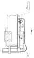
- FIG. 1is a side view of a camera crane with the crane arm retracted.
- FIG. 2is a side of the camera crane shown in FIG. 1 with the crane arm extended and angled up.
- FIG. 3is an enlarged section view of elements of the hydraulic system of the camera crane shown in FIGS. 1 and 2 .
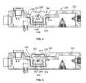
- FIG. 4is a side view in part section view of a hand controller that may be used with the camera crane shown in FIGS. 1-3 .
- FIG. 5is a section view of hand controller shown in FIG. 4 .
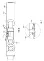
- FIG. 6is a top view of the hand controller shown in FIGS. 4 and 5 .
- FIG. 7is an enlarged section view detail of the rocker shaft shown in FIG. 6 .
- FIG. 8is a left side view of the rocker button.
- FIG. 9is a section view of the rocker button shown in FIG. 8 .
- FIG. 10is a right side view of the rocker button shown in FIGS. 8 and 9 .
- FIG. 11is a perspective view of the potentiometer assembly shown in FIG. 5 .
- FIG. 12is a perspective view of the potentiometer housing shown in FIG. 11 .
- FIG. 13is a side view of the potentiometer assembly shown in FIG. 11 .
- FIG. 14is a section view taken along line A-A of FIG. 13 .
- FIG. 15is a section view similar to FIG. 4 showing the rocker button in a full up or forward movement position.
- FIG. 16is a section view similar to FIG. 5 showing the rocker button in a full up or forward movement position, and proportionally reduced movement of the potentiometer shaft.
- a hand controller 275is connected to the hydraulic system 100 of a camera crane 30 , via a cable or a wireless link.
- the hydraulic system 100includes a control valve 230 which controls telescoping movement of the camera crane 30 , for example as describe in U.S. patent application Ser. Nos. 11/835,509 and 11/555,124, and U.S. Pat. No. 7,128,479, incorporated herein by reference.
- the hand controller 275typically includes an enclosure or box 302 having one or more electrical switches or other controls that may be linked to the hydraulic system or other component, wirelessly or via cables connected to connectors on the box.
- a rocker switch assembly 304may be provided in the box 302 with a rocker button 310 pivotally supported on a shaft 338 , and with the top of the rocker button extending up through an opening 320 in the box 302 .
- front and back finger surfaces 346may be provided on opposite ends of the opening 320 .
- the rocker switch assembly 304may include a bracket 308 attached to the box 302 , and a switch housing 316 attached to the bracket 308 .
- a spacer 348may be attached to the bracket to set the vertical position of the rocker switch assembly 304 .
- a low friction washer 350such as a Teflon (fluorine resins) washer can be positioned around the shaft 338 , with a resilient element 352 , such as a rubber O-ring between the washer 350 and a sidewall of the box 302 .
- the rocker button 310is pivotally supported on the rocker shaft 338 .
- the washer 350 and the resilient element 352add drag to movement of the rocker button 310 , to dampen rocker button movements.
- a rocker pin 314is attached to an extension arm 322 .
- a shaft 324 of a variable resistor 318extends out of the switch housing 316 .
- Levers 326 and 328 , a spring 330 and a washer 332are positioned around the shaft.
- An arm 322is rigidly attached to the shaft 324 .
- the spring 330 and the arms 326 and 328act to urge the arm 322 toward a center position, with the arms pressing against a center post 334 on the switch housing 316 .
- Electrical contacts 354extend out of the back of the switch housing 316 , for making electrical connections to the variable resistor 318 within the switch housing.
- a slot 340 at the lower end of the arm 322is dimensioned to fit around the rocker pin 314 .
- the shaft 324 of the variable resistor 318is positioned by dimension DD above the rocker shaft 338 .
- the rocker pin 314extends into the slot 340 of the arm 322 . Consequently, rotation or pivoting of the rocker button 310 correspondingly rotates the arm 322 about the shaft 324 .
- rotation of the shaft 324is only a fraction of the rotation of the shaft 338 .
- the rocker button 310When a user presses the front end of the rocker button 310 into the full down position, as shown in FIG. 15 , the rocker button 310 bottoms out against a stop ledge 342 on the switch housing 316 .
- the rocker buttonrotates through an angle BB from a center or neutral position to the maximum forward position.
- the angle BBcan vary in different designs. In the example shown angle BB is about 36 degrees.
- the shaft 324 of the variable resistorrotates through a smaller angle CC, for example about 18 degrees.
- the controller 275is accordingly de-sensitized because the physical movement of the rocker button 310 result in a proportionally reduced change in the resistance of the variable resistor, and correspondingly proportionally reduced movement of the crane arm.
- the rotation reducing mechanical linkage between rocker button and the variable resistormakes smooth control of the crane easier to achieve, even for less experienced crane operators.
- the spring 330urges the button back to the center position.
- the drag provided by the resilient member 352prevents the rocker button from snapping quickly back to center. Rather, due to the drag, when released, the rocker button rotates smoothly back to center with no overshoot. This avoids erratic or jerking movement of the crane arm. Noise and stress on crane arm components are reduced or eliminated, even when the crane arm is operated by less experienced personnel.
- the rocker button 310may be designed so that the top of front end of the button is about flush with the surface of the box 302 at the recess 306 when the bottom of the rocker button contacts the forward stop 342 . This provides the operator with a tactile indicator that the rocker button has reached its forward limit of travel.
- the features and operations described aboveapply as well to rearward movement of the rocker button, i.e., when the user presses down on the back end of the rocker button.
- the variable resistormay be replaced by other electronic components, such as an amplifier, which can covert the physical movement of the rocker button into electrical signals.
Landscapes
- Mechanical Control Devices (AREA)
Abstract
Description
Camera cranes are often used in motion picture and television production. The motion picture or television camera is typically mounted on a crane arm supported on a mobile base, dolly, or truck. Camera cranes generally have a crane arm supported on a base, with a camera platform at one end of the arm, and a counter weight at the other end. The crane arm can be pivoted by hand to raise and lower the camera, and also to pan to the left or right side.
Telescoping camera cranes have a telescoping arm that can extend and retract, providing far more capability than fixed length crane arms. The telescoping movement of the arm may be driven electrically or hydraulically. Generally, the crane operator uses a hand held controller to control the crane movement. The hand held controller is linked via a cable or wirelessly to the electrical or hydraulic drive system. Smooth movements reduce unwanted noise and stress on crane components. However, achieving smooth movements can be difficult to achieve, especially for less experienced crane operators. Accordingly, engineering challenges remain in designing an improved controller for a camera crane.
A new controller for a camera crane which overcomes the above-described factors has now been invented. In one aspect, this new controller includes a rocker button pivotally supported in or on a controller housing about a first pivot axis. A shaft of an electrical component, such as a variable resistor, is on a second pivot axis spaced apart from the first pivot axis. An arm is attached to the shaft. A spring urges the arm to a center position. Movement of the rocker button moves the arm. Due to the offset of the first and second pivot axes, movement of the rocker button results in proportionally reduced movement of the shaft of the electronic component. Smooth crane arm movements are readily achieved as the controller is less sensitive to the operators hand or finger movements.
In a second aspect, the rocker button may be linked to the arm via a pin on the rocker button extending into a slot on the shaft. In a third aspect, the electrical component may be contained within component housing, with the shaft extending out of the housing. A stop post on the component housing, and levers around the shaft, may optionally be provided to operate with the spring to continuously urge the arm into the center position.
In a third aspect, a recess may be provided in the controller housing with finger surfaces adjacent to the front and back ends of the recess. A dampening element may used to dampen return movement of the rocker button against the force of the spring. The invention resides as well in sub combinations of the features described.
In the drawings, the same reference number indicates the same element in all of the views.
As shown inFIGS. 1 and 2 , ahand controller 275 is connected to thehydraulic system 100 of acamera crane 30, via a cable or a wireless link. As shown inFIG. 3 , thehydraulic system 100 includes acontrol valve 230 which controls telescoping movement of thecamera crane 30, for example as describe in U.S. patent application Ser. Nos. 11/835,509 and 11/555,124, and U.S. Pat. No. 7,128,479, incorporated herein by reference.
Turning toFIGS. 4-6 , thehand controller 275 typically includes an enclosure orbox 302 having one or more electrical switches or other controls that may be linked to the hydraulic system or other component, wirelessly or via cables connected to connectors on the box. Arocker switch assembly 304 may be provided in thebox 302 with arocker button 310 pivotally supported on ashaft 338, and with the top of the rocker button extending up through anopening 320 in thebox 302. As shown inFIG. 6 , front andback finger surfaces 346 may be provided on opposite ends of theopening 320.
Therocker switch assembly 304 may include abracket 308 attached to thebox 302, and aswitch housing 316 attached to thebracket 308. Aspacer 348 may be attached to the bracket to set the vertical position of therocker switch assembly 304. Referring toFIG. 7 , alow friction washer 350, such as a Teflon (fluorine resins) washer can be positioned around theshaft 338, with aresilient element 352, such as a rubber O-ring between thewasher 350 and a sidewall of thebox 302. Turning toFIGS. 8-10 , therocker button 310 is pivotally supported on therocker shaft 338. Thewasher 350 and theresilient element 352 add drag to movement of therocker button 310, to dampen rocker button movements. Arocker pin 314 is attached to anextension arm 322.
As shown inFIGS. 11-14 , ashaft 324 of avariable resistor 318 extends out of theswitch housing 316.Levers spring 330 and awasher 332 are positioned around the shaft. Anarm 322 is rigidly attached to theshaft 324. Thespring 330 and thearms arm 322 toward a center position, with the arms pressing against acenter post 334 on theswitch housing 316.Electrical contacts 354 extend out of the back of theswitch housing 316, for making electrical connections to thevariable resistor 318 within the switch housing. Aslot 340 at the lower end of thearm 322 is dimensioned to fit around therocker pin 314.
Referring toFIGS. 5 and 8 , theshaft 324 of thevariable resistor 318 is positioned by dimension DD above therocker shaft 338. Therocker pin 314 extends into theslot 340 of thearm 322. Consequently, rotation or pivoting of therocker button 310 correspondingly rotates thearm 322 about theshaft 324. However, due to the offset between theshafts shaft 324 is only a fraction of the rotation of theshaft 338.
When a user presses the front end of therocker button 310 into the full down position, as shown inFIG. 15 , therocker button 310 bottoms out against astop ledge 342 on theswitch housing 316. The rocker button rotates through an angle BB from a center or neutral position to the maximum forward position. The angle BB can vary in different designs. In the example shown angle BB is about 36 degrees. Due to the geometry described above, theshaft 324 of the variable resistor rotates through a smaller angle CC, for example about 18 degrees. Thecontroller 275 is accordingly de-sensitized because the physical movement of therocker button 310 result in a proportionally reduced change in the resistance of the variable resistor, and correspondingly proportionally reduced movement of the crane arm. The rotation reducing mechanical linkage between rocker button and the variable resistor makes smooth control of the crane easier to achieve, even for less experienced crane operators.
When the rocker button is released, thespring 330 urges the button back to the center position. The drag provided by theresilient member 352 prevents the rocker button from snapping quickly back to center. Rather, due to the drag, when released, the rocker button rotates smoothly back to center with no overshoot. This avoids erratic or jerking movement of the crane arm. Noise and stress on crane arm components are reduced or eliminated, even when the crane arm is operated by less experienced personnel.
As shown inFIGS. 15-18 , therocker button 310 may be designed so that the top of front end of the button is about flush with the surface of thebox 302 at therecess 306 when the bottom of the rocker button contacts theforward stop 342. This provides the operator with a tactile indicator that the rocker button has reached its forward limit of travel. The features and operations described above apply as well to rearward movement of the rocker button, i.e., when the user presses down on the back end of the rocker button. The variable resistor may be replaced by other electronic components, such as an amplifier, which can covert the physical movement of the rocker button into electrical signals.
Thus, novel designs and methods have been shown and described. Various changes and modifications may of course be made without departing from the spirit and scope of the invention. The invention, therefore, should not be limited except by the following claims, and their equivalents.
Claims (10)
1. A hand controller, comprising:
a controller housing;
a rocker button pivotally supported on the housing on a first pivot axis;
a variable resistor having a shaft on a second pivot axis spaced apart from the first pivot axis;
a cable or wireless link connecting an output of the variable resister to a hydraulic system;
an arm attached to the shaft, with a slot in a lower end of the arm;
a spring biasing the arm to a center position; and
a pin on the rocker button extending into the slot, with movement of the rocker button through a first angle rotating the shaft through a second angle less than the first angle.
2. The hand controller ofclaim 1 further comprising a shaft housing, with the variable resistor inside of the shaft housing and with the shaft extending out of the shaft housing, a stop post on the shaft housing, and first and second levers pivotally attached to the shaft and based by the spring to urge the arm into the center position.
3. The hand controller ofclaim 1 further a shaft housing, with the variable resistor inside of the shaft housing and with the shaft extending out of the shaft housing, and an up stop ledge and a down stop ledge on the shaft housing.
4. The hand controller ofclaim 3 with the rocker button having an upper and a lower first end and an upper and a lower second end, and further comprising:
a recess in the controller housing having first end second ends;
first and second finger surfaces adjacent to the upper first and second ends of the recess;
the upper first end of the rocker switch substantially flush with the first finger surface when the lower first eon of the rocker switch contacts the up stop ledge.
5. A hand controller, comprising:
a controller housing having a top surface;
a rocker button pivotally supported on the housing on a first pivot axis;
a variable resistor having a shaft on a second pivot axis spaced apart from and above the first pivot axis;
a cable or wireless link for providing an output signal of the variable resistor to a hydraulic system of a camera crane;
a spring biasing the arm to a center position; and
an angular movement reducing mechanical linkage connecting the rocker button to the shaft causing movement of the rocker button through a first angle to turn the shaft through a second angle less than the first angle.
6. The controller ofclaim 5 with the mechanical linkage comprising an arm attached to the shaft, and a pin slidably connecting the rocker button to the arm.
7. The hand controller ofclaim 5 where spacing between the first and second pivot axes is selected to cause pivoting of the rocker button through an angle AA to pivot the shaft through an angle of 20% to 80% of AA.
8. A hand controller for hydraulic system, comprising:
a hand-held controller housing;
a rocker button pivotally supported on the housing on a first pivot axis;
a variable resistor in a variable resistor housing, with the variable resistor having a shaft on a second pivot axis spaced apart from the first pivot axis, with the variable resistor electrically linked to a control valve in the hydraulic system;
an arm attached to the shaft with a slot in a lower end of the arm and a pin on the rocker button extending into the slot forming an angular movement reducing mechanical linkage connecting the rocker button to the shaft, causing movement of the rocker button through a first angle to turn the shaft through a second angle less than the first angle;
a spring biasing the arm to a center position;
a stop post on the variable resistor housing;
first and second levers pivotally attached to the shaft and biased by the spring to urge the arm into the center position.
9. The hand controller ofclaim 8 with the variable resistor electrically linked to the control valve via a cable connected to the controller housing.
10. The hand controller ofclaim 8 with the variable resistor electrically linked to the control valve via a wireless link in controller housing.
Priority Applications (2)
| Application Number | Priority Date | Filing Date | Title |
|---|---|---|---|
| US13/289,828US8576044B2 (en) | 2011-11-04 | 2011-11-04 | Hand controller for a camera crane |
| PCT/US2012/060889WO2013066635A1 (en) | 2011-11-04 | 2012-10-18 | Hand controller for a camera crane |
Applications Claiming Priority (1)
| Application Number | Priority Date | Filing Date | Title |
|---|---|---|---|
| US13/289,828US8576044B2 (en) | 2011-11-04 | 2011-11-04 | Hand controller for a camera crane |
Publications (2)
| Publication Number | Publication Date |
|---|---|
| US20130113599A1 US20130113599A1 (en) | 2013-05-09 |
| US8576044B2true US8576044B2 (en) | 2013-11-05 |
Family
ID=48192609
Family Applications (1)
| Application Number | Title | Priority Date | Filing Date |
|---|---|---|---|
| US13/289,828Active2031-11-13US8576044B2 (en) | 2011-11-04 | 2011-11-04 | Hand controller for a camera crane |
Country Status (2)
| Country | Link |
|---|---|
| US (1) | US8576044B2 (en) |
| WO (1) | WO2013066635A1 (en) |
Cited By (35)
| Publication number | Priority date | Publication date | Assignee | Title |
|---|---|---|---|---|
| US9709956B1 (en) | 2013-08-09 | 2017-07-18 | Apple Inc. | Tactile switch for an electronic device |
| US9753436B2 (en) | 2013-06-11 | 2017-09-05 | Apple Inc. | Rotary input mechanism for an electronic device |
| US9891651B2 (en) | 2016-02-27 | 2018-02-13 | Apple Inc. | Rotatable input mechanism having adjustable output |
| US9952558B2 (en) | 2015-03-08 | 2018-04-24 | Apple Inc. | Compressible seal for rotatable and translatable input mechanisms |
| US10002731B2 (en) | 2015-09-08 | 2018-06-19 | Apple Inc. | Rocker input mechanism |
| US10018966B2 (en) | 2015-04-24 | 2018-07-10 | Apple Inc. | Cover member for an input mechanism of an electronic device |
| US10019097B2 (en) | 2016-07-25 | 2018-07-10 | Apple Inc. | Force-detecting input structure |
| US10048802B2 (en) | 2014-02-12 | 2018-08-14 | Apple Inc. | Rejection of false turns of rotary inputs for electronic devices |
| US10061399B2 (en) | 2016-07-15 | 2018-08-28 | Apple Inc. | Capacitive gap sensor ring for an input device |
| US10102985B1 (en) | 2015-04-23 | 2018-10-16 | Apple Inc. | Thin profile sealed button assembly |
| US10145711B2 (en) | 2015-03-05 | 2018-12-04 | Apple Inc. | Optical encoder with direction-dependent optical properties having an optically anisotropic region to produce a first and a second light distribution |
| US10190891B1 (en) | 2014-07-16 | 2019-01-29 | Apple Inc. | Optical encoder for detecting rotational and axial movement |
| US10290440B2 (en) | 2014-01-31 | 2019-05-14 | Apple Inc. | Waterproof button assembly |
| US10296047B2 (en) | 2015-08-04 | 2019-05-21 | Apple Inc. | Input mechanism with deformable touch-sensitive material |
| US20200011758A1 (en)* | 2017-03-27 | 2020-01-09 | Anshuo Liu | Lopsided payload carriage gimbal for air and water-borne vehicles |
| US10551798B1 (en) | 2016-05-17 | 2020-02-04 | Apple Inc. | Rotatable crown for an electronic device |
| US10599101B2 (en) | 2014-09-02 | 2020-03-24 | Apple Inc. | Wearable electronic device |
| US10664074B2 (en) | 2017-06-19 | 2020-05-26 | Apple Inc. | Contact-sensitive crown for an electronic watch |
| US10831299B1 (en) | 2017-08-16 | 2020-11-10 | Apple Inc. | Force-sensing button for electronic devices |
| US10866619B1 (en) | 2017-06-19 | 2020-12-15 | Apple Inc. | Electronic device having sealed button biometric sensing system |
| US10962935B1 (en) | 2017-07-18 | 2021-03-30 | Apple Inc. | Tri-axis force sensor |
| US11079812B1 (en) | 2017-09-12 | 2021-08-03 | Apple Inc. | Modular button assembly for an electronic device |
| US11181863B2 (en) | 2018-08-24 | 2021-11-23 | Apple Inc. | Conductive cap for watch crown |
| US11194299B1 (en) | 2019-02-12 | 2021-12-07 | Apple Inc. | Variable frictional feedback device for a digital crown of an electronic watch |
| US11194298B2 (en) | 2018-08-30 | 2021-12-07 | Apple Inc. | Crown assembly for an electronic watch |
| US11269376B2 (en) | 2020-06-11 | 2022-03-08 | Apple Inc. | Electronic device |
| US11360440B2 (en) | 2018-06-25 | 2022-06-14 | Apple Inc. | Crown for an electronic watch |
| US11550268B2 (en) | 2020-06-02 | 2023-01-10 | Apple Inc. | Switch module for electronic crown assembly |
| US11561515B2 (en) | 2018-08-02 | 2023-01-24 | Apple Inc. | Crown for an electronic watch |
| US11796968B2 (en) | 2018-08-30 | 2023-10-24 | Apple Inc. | Crown assembly for an electronic watch |
| US11796961B2 (en) | 2018-08-24 | 2023-10-24 | Apple Inc. | Conductive cap for watch crown |
| US12092996B2 (en) | 2021-07-16 | 2024-09-17 | Apple Inc. | Laser-based rotation sensor for a crown of an electronic watch |
| US12189347B2 (en) | 2022-06-14 | 2025-01-07 | Apple Inc. | Rotation sensor for a crown of an electronic watch |
| US12259690B2 (en) | 2018-08-24 | 2025-03-25 | Apple Inc. | Watch crown having a conductive surface |
| US12432292B2 (en) | 2023-01-27 | 2025-09-30 | Apple Inc. | Handheld electronic device |
Families Citing this family (1)
| Publication number | Priority date | Publication date | Assignee | Title |
|---|---|---|---|---|
| US9619680B2 (en) | 2014-12-29 | 2017-04-11 | Eaton Corporation | Self-identifying control switch |
Citations (10)
| Publication number | Priority date | Publication date | Assignee | Title |
|---|---|---|---|---|
| GB312456A (en) | 1928-04-17 | 1929-05-30 | Edison Swan Electric Co Ltd | Improvements in and relating to electric switches |
| US4139831A (en)* | 1976-10-29 | 1979-02-13 | Georgii-Kobold August Heine Kg | Control for electrical positioning drives |
| US4795952A (en) | 1986-05-12 | 1989-01-03 | The Warner & Swasey Company | Joystick for three axis control of a powered element |
| US4843200A (en) | 1986-10-29 | 1989-06-27 | Legrand | Switch Mechanism having a conductive contact arm with a double pivot |
| US4899097A (en) | 1986-10-02 | 1990-02-06 | Chapman Leonard T | Motorized tang drive system |
| US5107955A (en)* | 1990-04-17 | 1992-04-28 | Japanic Corporation | Operation control mechanism of lifting apparatus |
| US5349323A (en) | 1992-06-11 | 1994-09-20 | Matsushita Electric Industrial Co., Ltd. | Seesaw manipulation-type variable resistor |
| US5469125A (en)* | 1993-04-15 | 1995-11-21 | Matsushita Electric Industrial Co., Ltd. | Rotary electronic device |
| US6450706B1 (en)* | 2000-05-31 | 2002-09-17 | Chapman/Leonard Studio Equipment | Camera crane |
| EP1657212A2 (en) | 1997-09-08 | 2006-05-17 | Crown Equipment Corporation | Personnel carrying vehicle |
- 2011
- 2011-11-04USUS13/289,828patent/US8576044B2/enactiveActive
- 2012
- 2012-10-18WOPCT/US2012/060889patent/WO2013066635A1/enactiveApplication Filing
Patent Citations (10)
| Publication number | Priority date | Publication date | Assignee | Title |
|---|---|---|---|---|
| GB312456A (en) | 1928-04-17 | 1929-05-30 | Edison Swan Electric Co Ltd | Improvements in and relating to electric switches |
| US4139831A (en)* | 1976-10-29 | 1979-02-13 | Georgii-Kobold August Heine Kg | Control for electrical positioning drives |
| US4795952A (en) | 1986-05-12 | 1989-01-03 | The Warner & Swasey Company | Joystick for three axis control of a powered element |
| US4899097A (en) | 1986-10-02 | 1990-02-06 | Chapman Leonard T | Motorized tang drive system |
| US4843200A (en) | 1986-10-29 | 1989-06-27 | Legrand | Switch Mechanism having a conductive contact arm with a double pivot |
| US5107955A (en)* | 1990-04-17 | 1992-04-28 | Japanic Corporation | Operation control mechanism of lifting apparatus |
| US5349323A (en) | 1992-06-11 | 1994-09-20 | Matsushita Electric Industrial Co., Ltd. | Seesaw manipulation-type variable resistor |
| US5469125A (en)* | 1993-04-15 | 1995-11-21 | Matsushita Electric Industrial Co., Ltd. | Rotary electronic device |
| EP1657212A2 (en) | 1997-09-08 | 2006-05-17 | Crown Equipment Corporation | Personnel carrying vehicle |
| US6450706B1 (en)* | 2000-05-31 | 2002-09-17 | Chapman/Leonard Studio Equipment | Camera crane |
Non-Patent Citations (1)
| Title |
|---|
| United States Patent and Trademark Office, International Search Report and Written Opinion for PCT/US12/060889, Jan. 23, 2013. |
Cited By (103)
| Publication number | Priority date | Publication date | Assignee | Title |
|---|---|---|---|---|
| US11531306B2 (en) | 2013-06-11 | 2022-12-20 | Apple Inc. | Rotary input mechanism for an electronic device |
| US9753436B2 (en) | 2013-06-11 | 2017-09-05 | Apple Inc. | Rotary input mechanism for an electronic device |
| US10234828B2 (en) | 2013-06-11 | 2019-03-19 | Apple Inc. | Rotary input mechanism for an electronic device |
| US9886006B2 (en) | 2013-06-11 | 2018-02-06 | Apple Inc. | Rotary input mechanism for an electronic device |
| US11886149B2 (en) | 2013-08-09 | 2024-01-30 | Apple Inc. | Tactile switch for an electronic device |
| US12181840B2 (en) | 2013-08-09 | 2024-12-31 | Apple Inc. | Tactile switch for an electronic device |
| US9971305B2 (en) | 2013-08-09 | 2018-05-15 | Apple Inc. | Tactile switch for an electronic device |
| US10962930B2 (en) | 2013-08-09 | 2021-03-30 | Apple Inc. | Tactile switch for an electronic device |
| US10216147B2 (en) | 2013-08-09 | 2019-02-26 | Apple Inc. | Tactile switch for an electronic device |
| US9709956B1 (en) | 2013-08-09 | 2017-07-18 | Apple Inc. | Tactile switch for an electronic device |
| US10331081B2 (en) | 2013-08-09 | 2019-06-25 | Apple Inc. | Tactile switch for an electronic device |
| US10331082B2 (en) | 2013-08-09 | 2019-06-25 | Apple Inc. | Tactile switch for an electronic device |
| US10732571B2 (en) | 2013-08-09 | 2020-08-04 | Apple Inc. | Tactile switch for an electronic device |
| US10175652B2 (en) | 2013-08-09 | 2019-01-08 | Apple Inc. | Tactile switch for an electronic device |
| US9836025B2 (en) | 2013-08-09 | 2017-12-05 | Apple Inc. | Tactile switch for an electronic device |
| US11205548B2 (en) | 2014-01-31 | 2021-12-21 | Apple Inc. | Waterproof button assembly |
| US10290440B2 (en) | 2014-01-31 | 2019-05-14 | Apple Inc. | Waterproof button assembly |
| US10222909B2 (en) | 2014-02-12 | 2019-03-05 | Apple Inc. | Rejection of false turns of rotary inputs for electronic devices |
| US11669205B2 (en) | 2014-02-12 | 2023-06-06 | Apple Inc. | Rejection of false turns of rotary inputs for electronic devices |
| US11347351B2 (en) | 2014-02-12 | 2022-05-31 | Apple Inc. | Rejection of false turns of rotary inputs for electronic devices |
| US10613685B2 (en) | 2014-02-12 | 2020-04-07 | Apple Inc. | Rejection of false turns of rotary inputs for electronic devices |
| US12307047B2 (en) | 2014-02-12 | 2025-05-20 | Apple Inc. | Rejection of false turns of rotary inputs for electronic devices |
| US10884549B2 (en) | 2014-02-12 | 2021-01-05 | Apple Inc. | Rejection of false turns of rotary inputs for electronic devices |
| US12045416B2 (en) | 2014-02-12 | 2024-07-23 | Apple Inc. | Rejection of false turns of rotary inputs for electronic devices |
| US10048802B2 (en) | 2014-02-12 | 2018-08-14 | Apple Inc. | Rejection of false turns of rotary inputs for electronic devices |
| US11015960B2 (en) | 2014-07-16 | 2021-05-25 | Apple Inc. | Optical encoder for detecting crown movement |
| US10190891B1 (en) | 2014-07-16 | 2019-01-29 | Apple Inc. | Optical encoder for detecting rotational and axial movement |
| US10627783B2 (en) | 2014-09-02 | 2020-04-21 | Apple Inc. | Wearable electronic device |
| US11762342B2 (en) | 2014-09-02 | 2023-09-19 | Apple Inc. | Wearable electronic device |
| US11567457B2 (en) | 2014-09-02 | 2023-01-31 | Apple Inc. | Wearable electronic device |
| US10942491B2 (en) | 2014-09-02 | 2021-03-09 | Apple Inc. | Wearable electronic device |
| US11221590B2 (en) | 2014-09-02 | 2022-01-11 | Apple Inc. | Wearable electronic device |
| US11474483B2 (en) | 2014-09-02 | 2022-10-18 | Apple Inc. | Wearable electronic device |
| US10599101B2 (en) | 2014-09-02 | 2020-03-24 | Apple Inc. | Wearable electronic device |
| US10613485B2 (en) | 2014-09-02 | 2020-04-07 | Apple Inc. | Wearable electronic device |
| US10620591B2 (en) | 2014-09-02 | 2020-04-14 | Apple Inc. | Wearable electronic device |
| US11002572B2 (en) | 2015-03-05 | 2021-05-11 | Apple Inc. | Optical encoder with direction-dependent optical properties comprising a spindle having an array of surface features defining a concave contour along a first direction and a convex contour along a second direction |
| US10655988B2 (en) | 2015-03-05 | 2020-05-19 | Apple Inc. | Watch with rotatable optical encoder having a spindle defining an array of alternating regions extending along an axial direction parallel to the axis of a shaft |
| US10145711B2 (en) | 2015-03-05 | 2018-12-04 | Apple Inc. | Optical encoder with direction-dependent optical properties having an optically anisotropic region to produce a first and a second light distribution |
| US9952558B2 (en) | 2015-03-08 | 2018-04-24 | Apple Inc. | Compressible seal for rotatable and translatable input mechanisms |
| US10845764B2 (en) | 2015-03-08 | 2020-11-24 | Apple Inc. | Compressible seal for rotatable and translatable input mechanisms |
| US11988995B2 (en) | 2015-03-08 | 2024-05-21 | Apple Inc. | Compressible seal for rotatable and translatable input mechanisms |
| US10037006B2 (en) | 2015-03-08 | 2018-07-31 | Apple Inc. | Compressible seal for rotatable and translatable input mechanisms |
| US10102985B1 (en) | 2015-04-23 | 2018-10-16 | Apple Inc. | Thin profile sealed button assembly |
| US10018966B2 (en) | 2015-04-24 | 2018-07-10 | Apple Inc. | Cover member for an input mechanism of an electronic device |
| US10222756B2 (en) | 2015-04-24 | 2019-03-05 | Apple Inc. | Cover member for an input mechanism of an electronic device |
| US10296047B2 (en) | 2015-08-04 | 2019-05-21 | Apple Inc. | Input mechanism with deformable touch-sensitive material |
| US10838461B2 (en) | 2015-08-04 | 2020-11-17 | Apple Inc. | Input mechanism with deformable touch-sensitive material |
| US10002731B2 (en) | 2015-09-08 | 2018-06-19 | Apple Inc. | Rocker input mechanism |
| US10579090B2 (en) | 2016-02-27 | 2020-03-03 | Apple Inc. | Rotatable input mechanism having adjustable output |
| US9891651B2 (en) | 2016-02-27 | 2018-02-13 | Apple Inc. | Rotatable input mechanism having adjustable output |
| US10551798B1 (en) | 2016-05-17 | 2020-02-04 | Apple Inc. | Rotatable crown for an electronic device |
| US12104929B2 (en) | 2016-05-17 | 2024-10-01 | Apple Inc. | Rotatable crown for an electronic device |
| US12086331B2 (en) | 2016-07-15 | 2024-09-10 | Apple Inc. | Capacitive gap sensor ring for an input device |
| US10379629B2 (en) | 2016-07-15 | 2019-08-13 | Apple Inc. | Capacitive gap sensor ring for an electronic watch |
| US10955937B2 (en) | 2016-07-15 | 2021-03-23 | Apple Inc. | Capacitive gap sensor ring for an input device |
| US11513613B2 (en) | 2016-07-15 | 2022-11-29 | Apple Inc. | Capacitive gap sensor ring for an input device |
| US10061399B2 (en) | 2016-07-15 | 2018-08-28 | Apple Inc. | Capacitive gap sensor ring for an input device |
| US10509486B2 (en) | 2016-07-15 | 2019-12-17 | Apple Inc. | Capacitive gap sensor ring for an electronic watch |
| US11720064B2 (en) | 2016-07-25 | 2023-08-08 | Apple Inc. | Force-detecting input structure |
| US12105479B2 (en) | 2016-07-25 | 2024-10-01 | Apple Inc. | Force-detecting input structure |
| US10572053B2 (en) | 2016-07-25 | 2020-02-25 | Apple Inc. | Force-detecting input structure |
| US11385599B2 (en) | 2016-07-25 | 2022-07-12 | Apple Inc. | Force-detecting input structure |
| US10948880B2 (en) | 2016-07-25 | 2021-03-16 | Apple Inc. | Force-detecting input structure |
| US10019097B2 (en) | 2016-07-25 | 2018-07-10 | Apple Inc. | Force-detecting input structure |
| US10296125B2 (en) | 2016-07-25 | 2019-05-21 | Apple Inc. | Force-detecting input structure |
| US20200011758A1 (en)* | 2017-03-27 | 2020-01-09 | Anshuo Liu | Lopsided payload carriage gimbal for air and water-borne vehicles |
| US10836470B2 (en)* | 2017-03-27 | 2020-11-17 | Anshuo Liu | Lopsided payload carriage gimbal for air and water-borne vehicles |
| US10866619B1 (en) | 2017-06-19 | 2020-12-15 | Apple Inc. | Electronic device having sealed button biometric sensing system |
| US10664074B2 (en) | 2017-06-19 | 2020-05-26 | Apple Inc. | Contact-sensitive crown for an electronic watch |
| US11379011B1 (en) | 2017-06-19 | 2022-07-05 | Apple Inc. | Electronic device having sealed button biometric sensing system |
| US12181927B2 (en) | 2017-06-19 | 2024-12-31 | Apple Inc. | Electronic device having sealed button biometric sensing system |
| US11797057B2 (en) | 2017-06-19 | 2023-10-24 | Apple Inc. | Electronic device having sealed button biometric sensing system |
| US12066795B2 (en) | 2017-07-18 | 2024-08-20 | Apple Inc. | Tri-axis force sensor |
| US10962935B1 (en) | 2017-07-18 | 2021-03-30 | Apple Inc. | Tri-axis force sensor |
| US10831299B1 (en) | 2017-08-16 | 2020-11-10 | Apple Inc. | Force-sensing button for electronic devices |
| US11079812B1 (en) | 2017-09-12 | 2021-08-03 | Apple Inc. | Modular button assembly for an electronic device |
| US12130672B1 (en) | 2017-09-12 | 2024-10-29 | Apple Inc. | Modular button assembly for an electronic device |
| US11360440B2 (en) | 2018-06-25 | 2022-06-14 | Apple Inc. | Crown for an electronic watch |
| US12105480B2 (en) | 2018-06-25 | 2024-10-01 | Apple Inc. | Crown for an electronic watch |
| US11754981B2 (en) | 2018-06-25 | 2023-09-12 | Apple Inc. | Crown for an electronic watch |
| US11561515B2 (en) | 2018-08-02 | 2023-01-24 | Apple Inc. | Crown for an electronic watch |
| US12282302B2 (en) | 2018-08-02 | 2025-04-22 | Apple Inc. | Crown for an electronic watch |
| US11906937B2 (en) | 2018-08-02 | 2024-02-20 | Apple Inc. | Crown for an electronic watch |
| US11181863B2 (en) | 2018-08-24 | 2021-11-23 | Apple Inc. | Conductive cap for watch crown |
| US12276943B2 (en) | 2018-08-24 | 2025-04-15 | Apple Inc. | Conductive cap for watch crown |
| US12259690B2 (en) | 2018-08-24 | 2025-03-25 | Apple Inc. | Watch crown having a conductive surface |
| US11796961B2 (en) | 2018-08-24 | 2023-10-24 | Apple Inc. | Conductive cap for watch crown |
| US11796968B2 (en) | 2018-08-30 | 2023-10-24 | Apple Inc. | Crown assembly for an electronic watch |
| US11194298B2 (en) | 2018-08-30 | 2021-12-07 | Apple Inc. | Crown assembly for an electronic watch |
| US12326697B2 (en) | 2018-08-30 | 2025-06-10 | Apple Inc. | Crown assembly for an electronic watch |
| US12346070B2 (en) | 2019-02-12 | 2025-07-01 | Apple Inc. | Variable frictional feedback device for a digital crown of an electronic watch |
| US11860587B2 (en) | 2019-02-12 | 2024-01-02 | Apple Inc. | Variable frictional feedback device for a digital crown of an electronic watch |
| US11194299B1 (en) | 2019-02-12 | 2021-12-07 | Apple Inc. | Variable frictional feedback device for a digital crown of an electronic watch |
| US12189342B2 (en) | 2020-06-02 | 2025-01-07 | Apple Inc. | Switch module for electronic crown assembly |
| US11550268B2 (en) | 2020-06-02 | 2023-01-10 | Apple Inc. | Switch module for electronic crown assembly |
| US11815860B2 (en) | 2020-06-02 | 2023-11-14 | Apple Inc. | Switch module for electronic crown assembly |
| US11635786B2 (en) | 2020-06-11 | 2023-04-25 | Apple Inc. | Electronic optical sensing device |
| US11983035B2 (en) | 2020-06-11 | 2024-05-14 | Apple Inc. | Electronic device |
| US11269376B2 (en) | 2020-06-11 | 2022-03-08 | Apple Inc. | Electronic device |
| US12092996B2 (en) | 2021-07-16 | 2024-09-17 | Apple Inc. | Laser-based rotation sensor for a crown of an electronic watch |
| US12189347B2 (en) | 2022-06-14 | 2025-01-07 | Apple Inc. | Rotation sensor for a crown of an electronic watch |
| US12432292B2 (en) | 2023-01-27 | 2025-09-30 | Apple Inc. | Handheld electronic device |
Also Published As
| Publication number | Publication date |
|---|---|
| WO2013066635A1 (en) | 2013-05-10 |
| US20130113599A1 (en) | 2013-05-09 |
Similar Documents
| Publication | Publication Date | Title |
|---|---|---|
| US8576044B2 (en) | Hand controller for a camera crane | |
| EP2802965B1 (en) | Input device comprising a touch-sensitive input surface | |
| US5684512A (en) | Ergonomic apparatus for controlling video or computer equipment | |
| EP2898762B1 (en) | Variable speed control systems and methods for walk-behind working machines | |
| US10073489B2 (en) | Rolling return to neutral depressable control | |
| KR101488209B1 (en) | Position control apparatus using by joystic | |
| EP2835084B1 (en) | Glass-wiping device | |
| JP2000322193A (en) | Gimbals fitting type joy stick having z-axis switch | |
| CN100567135C (en) | Multi-way valve operation mechanism for fork lift | |
| US20190066884A1 (en) | Insulated joystick assembly | |
| WO2015161389A1 (en) | Switch | |
| US20120279340A1 (en) | Pedal assembly for steering systems | |
| CN205028829U (en) | A 3D rotary joystick control device | |
| EP2948368B1 (en) | Passive control stick | |
| JP6915506B2 (en) | Working machine operation lever device | |
| CN214311493U (en) | Multi-degree-of-freedom industrial control handle structure | |
| JP2015158970A (en) | multi-directional input device | |
| KR101584215B1 (en) | Multi Function Integrating Switch | |
| CN204031899U (en) | The shrub and hedge trimmer that a kind of double trigger controls | |
| WO2011075675A3 (en) | Multi motion switch with multiplier arm | |
| JP2010211321A (en) | Joystick controller | |
| CN111540189B (en) | A multifunctional single-handed remote control | |
| PL225105B1 (en) | Apparatus for controlling with a scale of six degrees of freedom | |
| US20230312035A1 (en) | Turn signal switch | |
| JP7524727B2 (en) | Industrial Remote Controller |
Legal Events
| Date | Code | Title | Description |
|---|---|---|---|
| AS | Assignment | Owner name:CHAPMAN/LEONARD STUDIO EQUIPMENT, INC., CALIFORNIA Free format text:ASSIGNMENT OF ASSIGNORS INTEREST;ASSIGNOR:CHAPMAN, LEONARD T.;REEL/FRAME:027179/0780 Effective date:20111101 | |
| STCF | Information on status: patent grant | Free format text:PATENTED CASE | |
| FPAY | Fee payment | Year of fee payment:4 | |
| MAFP | Maintenance fee payment | Free format text:PAYMENT OF MAINTENANCE FEE, 8TH YR, SMALL ENTITY (ORIGINAL EVENT CODE: M2552); ENTITY STATUS OF PATENT OWNER: SMALL ENTITY Year of fee payment:8 | |
| MAFP | Maintenance fee payment | Free format text:PAYMENT OF MAINTENANCE FEE, 12TH YR, SMALL ENTITY (ORIGINAL EVENT CODE: M2553); ENTITY STATUS OF PATENT OWNER: SMALL ENTITY Year of fee payment:12 |