US8575642B1 - Optical devices having reflection mode wavelength material - Google Patents
Optical devices having reflection mode wavelength materialDownload PDFInfo
- Publication number
- US8575642B1 US8575642B1US13/600,988US201213600988AUS8575642B1US 8575642 B1US8575642 B1US 8575642B1US 201213600988 AUS201213600988 AUS 201213600988AUS 8575642 B1US8575642 B1US 8575642B1
- Authority
- US
- United States
- Prior art keywords
- wavelength
- selective material
- optical device
- led
- light
- Prior art date
- Legal status (The legal status is an assumption and is not a legal conclusion. Google has not performed a legal analysis and makes no representation as to the accuracy of the status listed.)
- Expired - Fee Related
Links
- 239000000463materialSubstances0.000titleclaimsabstractdescription86
- 230000003287optical effectEffects0.000titleclaimsdescription40
- 239000000758substrateSubstances0.000claimsabstractdescription49
- OAICVXFJPJFONN-UHFFFAOYSA-NPhosphorusChemical compound[P]OAICVXFJPJFONN-UHFFFAOYSA-N0.000claimsdescription70
- 239000011248coating agentSubstances0.000claimsdescription36
- 238000000576coating methodMethods0.000claimsdescription36
- 238000004519manufacturing processMethods0.000claimsdescription15
- 239000002245particleSubstances0.000claimsdescription11
- 239000004065semiconductorSubstances0.000claimsdescription11
- 239000000919ceramicSubstances0.000claimsdescription6
- 239000002105nanoparticleSubstances0.000claimsdescription5
- 239000002096quantum dotSubstances0.000claimsdescription4
- 230000004044responseEffects0.000claimsdescription4
- 238000000034methodMethods0.000abstractdescription18
- 230000005670electromagnetic radiationEffects0.000abstractdescription12
- 229910002601GaNInorganic materials0.000abstractdescription10
- JMASRVWKEDWRBT-UHFFFAOYSA-NGallium nitrideChemical compound[Ga]#NJMASRVWKEDWRBT-UHFFFAOYSA-N0.000abstractdescription4
- 238000010586diagramMethods0.000description37
- 125000006850spacer groupChemical group0.000description19
- 238000006243chemical reactionMethods0.000description11
- 239000008393encapsulating agentSubstances0.000description8
- VYPSYNLAJGMNEJ-UHFFFAOYSA-NSilicium dioxideChemical compoundO=[Si]=OVYPSYNLAJGMNEJ-UHFFFAOYSA-N0.000description7
- 238000002310reflectometryMethods0.000description7
- XUIMIQQOPSSXEZ-UHFFFAOYSA-NSiliconChemical compound[Si]XUIMIQQOPSSXEZ-UHFFFAOYSA-N0.000description5
- 230000006870functionEffects0.000description5
- 229910052710siliconInorganic materials0.000description5
- 239000010703siliconSubstances0.000description5
- 229910052688GadoliniumInorganic materials0.000description4
- GWEVSGVZZGPLCZ-UHFFFAOYSA-NTitan oxideChemical compoundO=[Ti]=OGWEVSGVZZGPLCZ-UHFFFAOYSA-N0.000description4
- 229910052681coesiteInorganic materials0.000description4
- 229910052906cristobaliteInorganic materials0.000description4
- 238000005286illuminationMethods0.000description4
- 150000002500ionsChemical class0.000description4
- 230000005693optoelectronicsEffects0.000description4
- 239000000377silicon dioxideSubstances0.000description4
- 239000007787solidSubstances0.000description4
- 229910052682stishoviteInorganic materials0.000description4
- 229910052905tridymiteInorganic materials0.000description4
- 229910052727yttriumInorganic materials0.000description4
- 229910052725zincInorganic materials0.000description4
- 230000008901benefitEffects0.000description3
- 230000005540biological transmissionEffects0.000description3
- 239000002019doping agentSubstances0.000description3
- 238000005530etchingMethods0.000description3
- 229910052733galliumInorganic materials0.000description3
- 239000007789gasSubstances0.000description3
- 229910052746lanthanumInorganic materials0.000description3
- 230000008635plant growthEffects0.000description3
- 229910052765LutetiumInorganic materials0.000description2
- 229910017623MgSi2Inorganic materials0.000description2
- 229910052771TerbiumInorganic materials0.000description2
- PNEYBMLMFCGWSK-UHFFFAOYSA-Naluminium oxideInorganic materials[O-2].[O-2].[O-2].[Al+3].[Al+3]PNEYBMLMFCGWSK-UHFFFAOYSA-N0.000description2
- 239000011230binding agentSubstances0.000description2
- 229910052801chlorineInorganic materials0.000description2
- 238000004891communicationMethods0.000description2
- 239000004020conductorSubstances0.000description2
- 229910052736halogenInorganic materials0.000description2
- 150000002367halogensChemical class0.000description2
- 229910052738indiumInorganic materials0.000description2
- APFVFJFRJDLVQX-UHFFFAOYSA-Nindium atomChemical compound[In]APFVFJFRJDLVQX-UHFFFAOYSA-N0.000description2
- 229910052909inorganic silicateInorganic materials0.000description2
- 230000003993interactionEffects0.000description2
- 229920001296polysiloxanePolymers0.000description2
- 229910052721tungstenInorganic materials0.000description2
- 229910016066BaSiInorganic materials0.000description1
- 229910004829CaWO4Inorganic materials0.000description1
- 229910005540GaPInorganic materials0.000description1
- GYHNNYVSQQEPJS-UHFFFAOYSA-NGalliumChemical compound[Ga]GYHNNYVSQQEPJS-UHFFFAOYSA-N0.000description1
- 229910020440K2SiF6Inorganic materials0.000description1
- 229910017414LaAlInorganic materials0.000description1
- 229910052779NeodymiumInorganic materials0.000description1
- 229910052772SamariumInorganic materials0.000description1
- 229910003564SiAlONInorganic materials0.000description1
- BQCADISMDOOEFD-UHFFFAOYSA-NSilverChemical compound[Ag]BQCADISMDOOEFD-UHFFFAOYSA-N0.000description1
- 229910004412SrSi2Inorganic materials0.000description1
- 229910052776ThoriumInorganic materials0.000description1
- 229910052775ThuliumInorganic materials0.000description1
- 229910052769YtterbiumInorganic materials0.000description1
- AJGDITRVXRPLBY-UHFFFAOYSA-Naluminum indiumChemical compound[Al].[In]AJGDITRVXRPLBY-UHFFFAOYSA-N0.000description1
- 229910052787antimonyInorganic materials0.000description1
- 230000015572biosynthetic processEffects0.000description1
- 229910052797bismuthInorganic materials0.000description1
- 229910052794bromiumInorganic materials0.000description1
- 229910052793cadmiumInorganic materials0.000description1
- 150000001768cationsChemical class0.000description1
- 229910010293ceramic materialInorganic materials0.000description1
- 210000001072colonAnatomy0.000description1
- 230000008602contractionEffects0.000description1
- 239000013078crystalSubstances0.000description1
- 238000011161developmentMethods0.000description1
- 230000018109developmental processEffects0.000description1
- 229910052637diopsideInorganic materials0.000description1
- 238000005553drillingMethods0.000description1
- 238000005516engineering processMethods0.000description1
- 229910052731fluorineInorganic materials0.000description1
- 238000009472formulationMethods0.000description1
- HZXMRANICFIONG-UHFFFAOYSA-Ngallium phosphideChemical compound[Ga]#PHZXMRANICFIONG-UHFFFAOYSA-N0.000description1
- 239000011521glassSubstances0.000description1
- 230000012010growthEffects0.000description1
- -1materialsChemical compound0.000description1
- QSHDDOUJBYECFT-UHFFFAOYSA-NmercuryChemical compound[Hg]QSHDDOUJBYECFT-UHFFFAOYSA-N0.000description1
- 229910052753mercuryInorganic materials0.000description1
- 239000000203mixtureSubstances0.000description1
- 229910052750molybdenumInorganic materials0.000description1
- 229910052759nickelInorganic materials0.000description1
- 150000004767nitridesChemical class0.000description1
- QJGQUHMNIGDVPM-UHFFFAOYSA-Nnitrogen groupChemical group[N]QJGQUHMNIGDVPM-UHFFFAOYSA-N0.000description1
- 229910052763palladiumInorganic materials0.000description1
- 238000007747platingMethods0.000description1
- 230000010287polarizationEffects0.000description1
- 230000008569processEffects0.000description1
- 230000005855radiationEffects0.000description1
- 230000006798recombinationEffects0.000description1
- 238000005215recombinationMethods0.000description1
- 239000002210silicon-based materialSubstances0.000description1
- 229910052709silverInorganic materials0.000description1
- 239000004332silverSubstances0.000description1
- WFKWXMTUELFFGS-UHFFFAOYSA-NtungstenChemical compound[W]WFKWXMTUELFFGS-UHFFFAOYSA-N0.000description1
- 239000010937tungstenSubstances0.000description1
- 230000005428wave functionEffects0.000description1
Images


Classifications
- H—ELECTRICITY
- H10—SEMICONDUCTOR DEVICES; ELECTRIC SOLID-STATE DEVICES NOT OTHERWISE PROVIDED FOR
- H10H—INORGANIC LIGHT-EMITTING SEMICONDUCTOR DEVICES HAVING POTENTIAL BARRIERS
- H10H20/00—Individual inorganic light-emitting semiconductor devices having potential barriers, e.g. light-emitting diodes [LED]
- H10H20/80—Constructional details
- H10H20/84—Coatings, e.g. passivation layers or antireflective coatings
- H—ELECTRICITY
- H10—SEMICONDUCTOR DEVICES; ELECTRIC SOLID-STATE DEVICES NOT OTHERWISE PROVIDED FOR
- H10H—INORGANIC LIGHT-EMITTING SEMICONDUCTOR DEVICES HAVING POTENTIAL BARRIERS
- H10H20/00—Individual inorganic light-emitting semiconductor devices having potential barriers, e.g. light-emitting diodes [LED]
- H10H20/80—Constructional details
- H10H20/85—Packages
- H10H20/851—Wavelength conversion means
- H10H20/8515—Wavelength conversion means not being in contact with the bodies
- H—ELECTRICITY
- H01—ELECTRIC ELEMENTS
- H01L—SEMICONDUCTOR DEVICES NOT COVERED BY CLASS H10
- H01L2224/00—Indexing scheme for arrangements for connecting or disconnecting semiconductor or solid-state bodies and methods related thereto as covered by H01L24/00
- H01L2224/01—Means for bonding being attached to, or being formed on, the surface to be connected, e.g. chip-to-package, die-attach, "first-level" interconnects; Manufacturing methods related thereto
- H01L2224/42—Wire connectors; Manufacturing methods related thereto
- H01L2224/47—Structure, shape, material or disposition of the wire connectors after the connecting process
- H01L2224/48—Structure, shape, material or disposition of the wire connectors after the connecting process of an individual wire connector
- H01L2224/4805—Shape
- H01L2224/4809—Loop shape
- H01L2224/48091—Arched
- H—ELECTRICITY
- H01—ELECTRIC ELEMENTS
- H01L—SEMICONDUCTOR DEVICES NOT COVERED BY CLASS H10
- H01L2224/00—Indexing scheme for arrangements for connecting or disconnecting semiconductor or solid-state bodies and methods related thereto as covered by H01L24/00
- H01L2224/01—Means for bonding being attached to, or being formed on, the surface to be connected, e.g. chip-to-package, die-attach, "first-level" interconnects; Manufacturing methods related thereto
- H01L2224/42—Wire connectors; Manufacturing methods related thereto
- H01L2224/47—Structure, shape, material or disposition of the wire connectors after the connecting process
- H01L2224/48—Structure, shape, material or disposition of the wire connectors after the connecting process of an individual wire connector
- H01L2224/484—Connecting portions
- H01L2224/48463—Connecting portions the connecting portion on the bonding area of the semiconductor or solid-state body being a ball bond
- H01L2224/48464—Connecting portions the connecting portion on the bonding area of the semiconductor or solid-state body being a ball bond the other connecting portion not on the bonding area also being a ball bond, i.e. ball-to-ball
- H—ELECTRICITY
- H10—SEMICONDUCTOR DEVICES; ELECTRIC SOLID-STATE DEVICES NOT OTHERWISE PROVIDED FOR
- H10H—INORGANIC LIGHT-EMITTING SEMICONDUCTOR DEVICES HAVING POTENTIAL BARRIERS
- H10H20/00—Individual inorganic light-emitting semiconductor devices having potential barriers, e.g. light-emitting diodes [LED]
- H10H20/80—Constructional details
- H10H20/85—Packages
- H10H20/852—Encapsulations
- H10H20/853—Encapsulations characterised by their shape
- H—ELECTRICITY
- H10—SEMICONDUCTOR DEVICES; ELECTRIC SOLID-STATE DEVICES NOT OTHERWISE PROVIDED FOR
- H10H—INORGANIC LIGHT-EMITTING SEMICONDUCTOR DEVICES HAVING POTENTIAL BARRIERS
- H10H20/00—Individual inorganic light-emitting semiconductor devices having potential barriers, e.g. light-emitting diodes [LED]
- H10H20/80—Constructional details
- H10H20/85—Packages
- H10H20/855—Optical field-shaping means, e.g. lenses
Definitions
- This disclosurerelates generally to lighting techniques, and more particularly to techniques for transmitting electromagnetic radiation from LED devices, such as ultra-violet, violet, blue, blue and yellow, and/or blue and green electromagnetic radiation, fabricated on bulk semipolar or nonpolar materials with use of wavelength converting materials such as phosphors, which emit light in a reflection mode.
- the substratecan include polar gallium nitride containing materials, and others.
- the disclosurecan be applied to applications such as white lighting, multi-colored lighting, general illumination, decorative lighting, automotive and aircraft lamps, street lights, lighting for plant growth, indicator lights, lighting for flat panel displays, other optoelectronic devices, and the like.
- the conventional light bulbcommonly called the “Edison bulb,” has been used for over one hundred years.
- the conventional light bulbuses a tungsten filament enclosed in a glass bulb sealed in a base, which is screwed into a socket.
- the socketis coupled to an AC or DC power source.
- the conventional light bulbcan be found commonly in houses, buildings, and outdoor lightings, and other areas requiring light.
- the conventional light bulbdissipates more than 90% of the energy used as thermal energy. Additionally, the conventional light bulb routinely fails often due to thermal expansion and contraction of the filament element.
- Fluorescent lightingovercomes some of the drawbacks of the conventional light bulb. Fluorescent lighting uses an optically clear tube structure filled with a halogen gas and mercury.
- a pair of electrodes in the halogen gasis coupled to an alternating power source through ballast. Once the gas has been excited, it discharges to emit light. Typically, the optically clear tube is coated with phosphors, which are excited by the light. Many building structures use fluorescent lighting and, more recently, fluorescent lighting has been fitted onto a base structure, which couples into a standard socket.
- Solid state lighting techniqueshave also been used. Solid state lighting relies upon semiconductor materials to produce light such as emitting diodes, commonly called LEDs.
- LEDsemitting diodes
- red LEDswere demonstrated and introduced into commerce. Red LEDs use Aluminum Indium Gallium Phosphide or AlInGaP semiconductor materials. Most recently, Shuji Nakamura pioneered the use of InGaN materials to produce LEDs emitting light in the blue color range for blue LEDs. The blue colored LEDs led to innovations such as solid state white lighting, the blue laser diode, which in turn enabled the Blu-RayTM (trademark of the Blu-Ray Disc Association) DVD player, and other developments. Other colored LEDs have also been proposed.
- High intensity UV, blue, and green LEDs based on GaNhave been proposed and even demonstrated with some success. Efficiencies have typically been highest in the UV-violet, dropping off as the emission wavelength increases to blue or green. Unfortunately, achieving high intensity, high-efficiency GaN-based green LEDs has been particularly problematic.
- the performance of optoelectronic devices fabricated on conventional c-plane GaNsuffer from strong internal polarization fields, which spatially separate the electron and hole wave functions and lead to poor radiative recombination efficiency. Since this phenomenon becomes more pronounced in InGaN layers with increased indium content for increased wavelength emission, extending the performance of UV or blue GaN-based LEDs to the blue-green or green regime has been difficult.
- the present disclosurerelates generally to lighting techniques and more particularly to techniques for transmitting electromagnetic radiation from LED devices, such as ultra-violet, violet, blue, blue and yellow, and/or blue and green electromagnetic radiation, fabricated on bulk semipolar or nonpolar materials with use of wavelength conversion materials such as phosphors, which emit light in a reflection mode.
- the substratecan include polar gallium nitride containing materials, and others.
- the disclosurecan be applied to applications such as white lighting, multi-colored lighting, general illumination, decorative lighting, automotive and aircraft lamps, street lights, lighting for plant growth, indicator lights, lighting for flat panel displays, other optoelectronic devices, and the like.
- the present disclosureprovides an optical device.
- the deviceincludes a substrate member having a surface region.
- the devicealso includes at least one LED configured overlying one or more portions of the surface region.
- the devicefurther includes a spacer member having two or more sidewalls, the sidewall being characterized by an angle.
- the deviceadditionally includes at least one wavelength conversion material disposed overlying the one or more sidewalls.
- the devicealso includes an optical member having a wavelength selective surface configured to block substantially direct emission of the at least one LED and configured to transmit at least one selected wavelength of reflected emission caused by an interaction of the reflected emission with the wavelength conversion material.
- the present disclosureprovides an optical device.
- the deviceincludes a substrate member having a surface region.
- the devicealso includes at least one LED configured overlying one or more portions of the surface region.
- the devicefurther includes at least one wavelength conversion material disposed over the surface region.
- the deviceincludes an optical member having a wavelength selective surface configured to block substantially direct emission of the at least one LED and configured to transmit at least one selected wavelength of reflected emission caused by an interaction of the reflected emission with the wavelength conversion material.
- the present device and methodprovides for an improved lighting technique with improved efficiencies.
- the present method and resulting structureare easier to implement using conventional technologies.
- a blue LED deviceis capable of emitting electromagnetic radiation at a wavelength range from about 450 nanometers to about 495 nanometers and the yellow-green LED device is capable of emitting electromagnetic radiation at a wavelength range from about 495 nanometers to about 590 nanometers, although there can also be some variations.
- FIG. 1is a simplified diagram illustrating an LED package, according to an embodiment of the present disclosure.
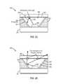
- FIG. 2Ais a simplified diagram illustrating light paths in an LED package, according to certain embodiments.
- FIG. 2Bis a simplified diagram illustrating light paths in an LED package, according to certain embodiments.
- FIG. 3is a diagram illustrating the reflectivity (% Transmission) of a dielectric filter designed to reflect 405 nm LED light as a function of the incident angle.
- FIG. 4Aillustrates a spacer with cavity walls coated with a highly reflective coating, according to embodiments of the present disclosure.
- FIG. 4Billustrates the reflectivity of the highly reflective coating of FIG. 4A as a function incident angle.
- FIG. 5A through FIG. 5Eare simplified diagrams illustrating a processing of coating phosphor material according to certain embodiments.
- FIG. 6is a simplified diagram illustrating an LED device electrically coupled to a conductive material with through vias, according to an embodiment of the present disclosure.
- FIG. 7illustrates an encapsulated LED, where the phosphor is coated on to the upper surface of the substrate member.
- FIG. 8illustrates a portion of the exit aperture below the critical angle that is covered by a mirror, according to an embodiment of the present disclosure.
- FIG. 9is a simplified diagram illustrating an LED package having a shaped exit aperture, according to embodiments of the present disclosure.
- FIG. 10is a simplified diagram illustrating an LED package having a shaped exit aperture, according to embodiments of the present disclosure.
- FIG. 11is a simplified diagram illustrating an LED package having reflective, angled sidewalls, according to certain embodiments of the present disclosure.
- FIG. 12is a simplified diagram illustrating an LED package having recess regions for phosphor material, according certain embodiments of the present disclosure.
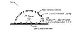
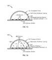
- FIG. 13is a simplified diagram illustrating an LED package having recess regions for phosphor material and a dichroic reflection coating disposed on a surface of a transparent dome, according to certain embodiments of the present disclosure.
- FIG. 14is a simplified diagram illustrating an LED package having recess regions for a first phosphor material disposed on the upper surface of the substrate, and for a second material and a third phosphor material dispersed within a volume bounded by a transparent dome, according to certain embodiments of the present disclosure.
- FIG. 15Ais a simplified diagram illustrating an LED package mounted within the form factor of an MR-16 lamp, according to certain embodiments of the present disclosure.
- FIG. 15Bis a diagram of the flexible assembly shown in FIG. 15A .
- FIG. 16Ais a simplified diagram illustrating an LED package mounted within the form factor of an A lamp, according to certain embodiments of the present disclosure.
- FIG. 16Bis a simplified diagram illustrating an LED package mounted within the form factor of an A-lamp, according to certain embodiments of the present disclosure.
- FIG. 17is a simplified diagram illustrating a method of manufacturing optical devices provided by the present disclosure having reflection mode wavelength material.
- the present disclosurerelates generally to lighting techniques and more particularly to techniques for transmitting electromagnetic radiation from LED devices, such as ultra-violet, violet, blue, blue and yellow, and/or blue and green electromagnetic radiation, fabricated on bulk semipolar or nonpolar materials with use of wavelength conversion materials such as phosphors, which emit light in a reflection mode.
- a substratecan include polar gallium nitride containing materials, and others.
- the disclosurecan be applied to applications such as white lighting, multi-colored lighting, general illumination, decorative lighting, automotive and aircraft lamps, street lights, lighting for plant growth, indicator lights, lighting for flat panel displays, other optoelectronic devices, and the like.
- domerefers to a rigid or semi-rigid shape having at least one concave surface.
- dichroicrefers to a material that reflects light at a first wavelength or at a first wavelength range, and passes, transmits, or is transparent to light at a second wavelength or at a second wavelength range.
- FIG. 1is a simplified diagram 100 illustrating an LED package according to an embodiment of the present disclosure.
- the LED packagecomprises an optic, a spacer, and a substrate.
- An LED deviceis positioned on the substrate.
- the LED packageis configured to achieve a high efficiency where the phosphor disposed on the sidewalls of the spacer operates in reflection.
- these componentsare fabricated at the wafer level and assembled before singulated into individual parts.
- substrate 101includes an LED 102 mounted on wafer 103 having silicon through vias 104 .
- Spacer 105includes angled sidewalls 106 defining air gap 107 .
- a high reflectivity omnidirectional coating 108is disposed on sidewalls 106 and a thick RGB phosphor, non-silicone based coating 109 is disposed on the coating 108 .
- the optic 110includes dielectric reflective regions 112 on the surface 113 facing the LED 102 and an optionally textured surface and/or lens 114 on the surface 115 directed away from the LED 102 .
- the optic 110may be attached to the spacer 105 and/or the spacer 105 may be attached to substrate 101 using wafer-to-wafer bonding methods, which in certain embodiments can form a hermetic seal.
- the dielectric reflective regionmay extend across the surface 113 of optic 110 .
- FIG. 2A and FIG. 2Bare simplified diagrams illustrating light paths in an LED package 200 .
- the LED package 200includes a substrate 201 , an LED device 202 , a spacer 203 having angled sidewalls 204 on which is deposited a phosphor layer 205 .
- An optic 206is mounted on top of the spacer 203 and includes wavelength reflective regions 207 disposed on the surface facing LED 202 .
- the spacer 203 and the optic 206define an air gap region 208 .
- the bottom layer of the optic 206is coated with regions having wavelength selective regions 207 such as a dielectric filter.
- the dielectric filtercan be a long pass filter that reflects the majority of light emitted by the LED 209 , but transmits the majority of the light emitted by the phosphor having a longer wavelength 210 .
- the dielectric reflector 207can reflect light of 405 nm (e.g., blue or violet color) back to the phosphor material 205 on spacer to cause the 405 nm light emitted by the LED device to be absorbed by the phosphor material 205 .
- the dielectric reflector 207may be configured to reflect other wavelength(s) as well.
- the dielectric reflectormay be disposed on certain regions of the optic or may be disposed across the entire surface of the optic.
- a dielectric reflective layermay be disposed on one or both surfaces of the optic.
- FIG. 2A and FIG. 2Bis a simplified diagram illustrating a dielectric filter used in an LED package.
- LED light of certain wavelength 209e.g., around 405 nm
- the phosphor material 205converts the reflected light 209 into a different wavelength 210 , and the converted light 210 passes through the optic 206 .
- FIG. 3is a simplified diagram 300 illustrating the reflectivity (% Transmission) of a dielectric filter designed to reflect 405 nm LED light as a function of incident angle.
- the top surface of the optichas a textured surface to diffuse the transmitted light.
- the spacercan be configured to separate the optic from the substrate to leave a cavity for the LED.
- the spaceris approximate 250 ⁇ m to 2,000 ⁇ m thick.
- the cavityis formed by etching silicon along the 1-0-0 plane to resulting in an etched facets walls have an angle of between about 50 degrees to about 60 degrees. Theses facet walls may be coated with a high reflectivity coating to form a high reflectivity cavity.
- the coatingcomprises a layer of silver coated with a quarter wave thickness of SiO 2 and quarter wave thickness of TiO 2 .
- FIG. 4Aillustrates a simplified diagram 400 of a spacer with cavity walls coated with the highly reflective coating according to certain embodiments of the present disclosure. As shown in FIG.
- spacer 401includes sidewalls 402 having an angle of 54.7°, and which define air gap 403 .
- Sidewalls 402are coated with a highly reflective coating 404 comprising a quarter wavelength thickness of SiO 2 and/or TiO 2 .
- the quarter wavelength thicknessis selected as appropriate for the wavelength or wavelength range intended to be reflected.
- FIG. 4Bshows the reflectivity of the highly reflective coating as a function of both wavelength of the incident light and the angle of incidence.
- the high reflector coatingis further coated with a layer of phosphor-containing material.
- the layer of phosphoris sufficiently thick such that almost all the incident light is back scattered and little of it reaches the mirrored surface, e.g., the highly reflective coating. This results in only a small amount of light emitted from the LED reaching the mirrored surface.
- FIG. 5A through FIG. 5Eis a simplified diagram 500 that illustrates a processing of coating phosphor material.
- FIG. 5Ashows a spacer 501 having angled sidewalls 502 on which a highly reflective coating (mirrored surface) 503 is deposited.
- a masked 504is deposited on portions of the spacer 501 .
- a phosphor suspended, for example, in a non-silicone binder 505is deposited or applied to the spacer 501 as shown in FIG. 5C .
- the binderis baked off, and as shown in FIG. 5E , the mask 504 is removed, to leave a phosphor layer 506 on mirrored surface 503 .
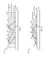
- FIG. 6is a simplified diagram 600 illustrating an LED device electrically coupled to a conductive material with through vias, according to an embodiment of the present disclosure.
- the LED device shown in FIG. 6includes an LED 601 , mounted on electrically conductive pads 602 disposed on a wafer 603 .
- LED 601may be electrically connected to adjoining conductive pads 604 by, for example, a wire bond 605 .
- Electrical contact pads 602 and 604may be electrically connected to electrically conductive areas on the opposite side 606 of wafer 603 by through vias 607 .
- Coating the phosphor on the side wallshas advantages, including: (i) the output of the aperture is not blocked by the phosphor coating thereby enabling higher emission efficiencies; (ii) the phosphor can be coated on surfaces that can have a heat sink to cool the phosphor; and (iii) phosphor backscattering is used advantageously to increase reflection from the package surfaces.
- the LED deviceis mounted on a thermally conductive but electrically insulating substrate.
- the substratehas electrically conductive patterns formed on the top and bottom surfaces. These top and bottom electrically conductive patterns are connected by through vias.
- the substrateis made of a ceramic material such as alumina or alumina nitride.
- the viasare fabricated by laser drilling and plating.
- the substrateis made of silicon.
- the surface of the siliconis made electrically insulating by a formation of a thermal oxide of SiO 2 on top of which the electrically conductive patterns are formed. Through the silicon material, vias are used to connect the top and bottom conductive patterns.
- the viasare formed by etching holes.
- the present disclosureprovides optical geometries based on total internal reflection to achieve an LED package in which the phosphor is positioned in a reflection geometry. Using a phosphor in refection mode has several advantages over traditional phosphor transmission geometries.
- FIG. 7is a simplified diagram 700 that illustrates an encapsulated LED, wherein the phosphor is coated on to the floor of an LED package.
- One of the goals of the configurations provided by the present disclosureis to minimize the light transmitted from the LED package below the critical angle.
- FIG. 7shows an LED 701 and phosphor coating 702 disposed on substrate 703 .
- the LED packageincludes sidewalls 704 having a reflective surface 705 and an encapsulant 706 within the cavity defined by the package. Refractive light 707 and internally reflected light 708 emitted by LED 701 are also shown.
- FIG. 8is a simplified diagram 800 that illustrates a portion of the exit aperture below the critical angle that covered by a mirror according to an embodiment of the present disclosure.
- the light emitted from the LED at less than the critical angleis now reflected back onto the phosphor.
- FIG. 8shows an LED 801 and phosphor coating 802 disposed on substrate 803 .
- the LED packageincludes sidewalls 804 having a reflective surface 805 and an encapsulant 806 within the cavity defined by the package. High angle light 807 emitted by LED 801 is reflected from mirror 808 onto the phosphor coating 802 and low angle light 809 is reflected at the surface 810 of encapsulant 806 by total internal reflection.
- FIG. 9is a simplified diagram 900 illustrating an LED package having a shaped aperture according to embodiments of the present disclosure. As shown, a portion of the exit aperture is shaped to ensure that all rays emitted directly from the LED will totally internally reflected back onto the phosphor.
- FIG. 9shows an LED 901 and phosphor coating 902 disposed on substrate 903 .
- the LED packageincludes sidewalls 904 having a reflective surface 905 and an encapsulant 906 within the cavity defined by the package. High angle light 907 emitted by LED 901 is reflected from shaped aperture 908 by internal reflection onto the phosphor coating 902 and low angle light 909 is reflected at the surface 910 of encapsulant 906 by total internal reflection.
- FIG. 10is a simplified diagram 1000 illustrating an LED package having a shaped exit aperture according to embodiments of the present disclosure. As shown, the exit aperture has a curved shape, which substantially eliminates the need of the reflective sides. In various embodiments, the reflectors are provided on the sides of the substrate.
- FIG. 10shows an LED 1001 and phosphor coating 1002 disposed on substrate 1003 .
- the LED packageincludes an encapsulant 1004 disposed over the LED 1001 and having a curved surface shape 1005 . Light 1006 emitted by LED 1001 is reflected from curved shape 1005 by total internal reflection onto the phosphor coating 1002 .
- FIG. 11is a simplified diagram 1100 illustrating an LED package according to an embodiment of the present disclosure.
- LED packagecomprises phosphor material residing on the same surface as the LED.
- the phosphor layercan be tens to hundreds of micron thick. This thickness can block the light emitting surfaces of the LED.
- the LED package as shown in FIG. 11includes a submount on the substrate that raises the LED device above the surface of the phosphor.
- FIG. 11shows LED 1101 on submount 1102 disposed on substrate 1103 .
- a thick phosphor layer 1104is disposed on the surface of the substrate 1103 surrounding LED 1101 .
- the packageincludes angled sidewalls 1105 coated with a reflective layer 1106 .
- An encapsulant 1107fills the cavity formed by the LED 1101 , the phosphor layer 1104 and the reflective angled sidewalls 1105 .
- FIG. 12is a simplified diagram 1200 illustrating an LED package having recess regions for phosphor material according to an embodiment of the present disclosure. As shown, a portion of floor of the LED package is raised where the LED device 1210 is mounted. For example, for package made of silicon, the raised platform is formed during the etching process.
- FIG. 12shows LED 1201 on raised surface 1202 disposed on substrate 1203 .
- a thick phosphor layer 1204is disposed on the recessed surface of the substrate 1203 surrounding LED 1201 .
- the packageincludes angled sidewalls 1205 coated with a reflective layer 1206 .
- An encapsulant 1207fills the cavity formed by the LED 1201 , the phosphor layer 1204 and the reflective angled sidewalls 1105 .
- LED packages having other configurations of wavelength conversion materialare described in U.S. Application Publication No. 2011/0186887, which is incorporated by reference herein for all purposes.
- FIG. 13is a simplified diagram illustrating an LED package having recess regions for phosphor material and a dichroic reflection coating upon a surface of a transparent dome.
- the embodimentdepicts an optical device 1300 built using a substrate member 1301 having an upper surface upon which upper surface light emitting diode (LED) devices 1302 are mounted so as to emit light at first selected wavelengths (e.g. a wavelength range of about 395 nm to about 430 nm).
- first selected wavelengthse.g. a wavelength range of about 395 nm to about 430 nm.
- a transparent dome 1303 with a dichroic reflection coating 1304that serves as a reflective member surrounding the LED devices 1302 .
- phosphor particles 1305are disposed on the upper surface of the substrate 1301 (e.g., in close proximity to the LED devices 1302 ) and at least some of the phosphor particles 1305 are wavelength-selective at a first wavelength (e.g., wavelengths in a range of about 395 nm to about 430 nm). As shown, the wavelength-selective material 1305 are disposed on the upper surface of the substrate member 1301 , and may also be disposed below the upper surface of the LED devices 1302 .
- the wavelength-selective material 1305emits light at second wavelength (e.g., wavelengths of about 440 nm to about 800 nm) in response to incidence of light at the first selected wavelength (e.g., light from the LED devices 1302 ).
- a reflective member 1304e.g., the transparent dome with at least a portion of the transparent dome having a dichroic reflection coating
- FIG. 14is a simplified diagram illustrating an LED package having recess regions for phosphor material and a dichroic reflection coating upon a surface of a transparent dome.
- the embodimentdepicts an optical device 1400 built using a substrate member 1401 having an upper surface upon which upper surface a light emitting diode (LED) device 1402 is mounted so as to emit light at first selected wavelengths (e.g. wavelength range of about 395 nm to about 430 nm).
- first selected wavelengthse.g. wavelength range of about 395 nm to about 430 nm.
- phosphor particles 1403are disposed on the upper surface of the substrate 1401 in close proximity to the LED devices 1402 as well as substantially throughout the volume 1404 bounded by the transparent dome 1405 .
- At least some of the wavelength-materials 1403are wavelength-selective at a first wavelength (e.g., absorbing light at a first wavelength and emitting light at a second wavelength). And, at least some other phosphor particles 1403 are wavelength-selective at the second wavelength (e.g., absorbing light at the second selected wavelength and emitting light at a third selected wavelength).
- a reflective membere.g., the transparent dome 1405 with at least a portion of the transparent dome having a dichroic reflection coating 1406 ) surrounds the LED devices 1402 , and allows substantially all light at the second and third selected wavelengths to escape from the optical device.
- FIG. 15Ais a simplified diagram illustrating an optical device 1500 in the embodiment of an LED package mounted within the form factor of an MR-16 lamp 1510 As shown, the dome surrounds the LED devices, and the LED devices are mounted into an assembly to connect to a power source.
- the assemblye.g., including the transparent dome
- FIG. 15Bshows details of the flexible assembly shown in FIG. 5A , including a driver 1501 , a dome 1502 over LED 1503 mounted on substrate member 1504 .
- FIG. 16Ais a simplified diagram illustrating an optical device 1600 in an embodiment of an LED package mounted within the form factor of an A lamp 1610 .
- the bulb of the A-lampforms a transparent dome 1601 that surrounds light source 1611 including LED devices 1602 mounted to substrate 1603 , and the LED devices 1602 are mounted into an assembly 1604 (e.g., a heat sink), which in turn is connected to a screw base 1605 to connect to a power source.
- the assemblye.g., including the transparent dome and the LED devices
- a portion 1606 of the bulb 1601is coated with a partially-reflective coating 1607 .
- the bulbsurrounds the LED devices.
- FIG. 16Bis a simplified diagram illustrating an LED package mounted within the form factor of an A-lamp.
- substantially all of the bulbis coated with a partially-reflective coating.
- the bulbsurrounds the LED devices.
- FIG. 16Bshows a form factor of an A-lamp with an LED light source 1611 mounted on an assembly 1612 , that includes a heatsink with fins 1613 connected to a screw base 1614 .
- LED light source 1611includes LED devices 1615 , mounted to a substrate member 1616 .
- the bulbincludes a transparent dome 1617 , the inner surface of which is coated with a partially reflective coating 1618 .
- FIG. 17is a simplified diagram illustrating a method for manufacturing embodiments of the herein-disclosed optical devices having reflection mode wavelength material, according to a method embodiment of the present disclosure.
- FIG. 17depicts a block diagram of a fabrication system to perform certain functions of a computer system.
- System 1700comprises at least one processor and at least one memory, the memory serving to store program instructions corresponding to the operations of the system. As shown, an operation can be implemented in whole or in part using program instructions accessible by a module.
- the modules of the fabrication systemare connected to a communication path 1705 , and any module can communicate with other modules over communication path 1705 .
- the modules of the systemcan, individually or in combination, perform method operations within system 1700 .
- FIG. 17implements a portion of a computerized fabrication system, shown as system 1700 , comprising a computer processor to execute a set of program code instructions and modules for accessing memory to hold program code instructions to perform: providing a substrate member having an upper surface (see module 1710 ); providing a light emitting diode (LED) device to emit light at first selected wavelengths, the LED mounted on the upper surface of the substrate member (see module 1720 ); providing a reflective member surrounding the LED, the reflective member comprising a dichroic reflection coating and a transparent dome (see module 1730 ); and providing at least some first wavelength-selective material disposed on the upper surface around the LED, an upper surface of the wavelength-selective material being below an upper surface of the LED, where the wavelength-selective material emits light at second wavelengths in response to incidence of first selected wavelength light from the LED and where the reflective member allows substantially all light at the second selected wavelengths to
- Wavelength conversion materialscan be ceramic or semiconductor particle phosphors, ceramic or semiconductor plate phosphors, organic or inorganic downconverters, upconverters (anti-stokes), nano-particles and other materials which provide wavelength conversion. Some examples are listed below:
- a phosphorhas two or more dopant ions (i.e. those ions following the colon in the above phosphors), this is to mean that the phosphor has at least one (but not necessarily all) of those dopant ions within the material. That is, as understood by those skilled in the art, this type of notation means that the phosphor can include any or all of those specified ions as dopants in the formulation.
- nanoparticles, quantum dots, semiconductor particles, and other types of materialscan be used as wavelength converting materials.
- the list aboveis representative and should not be taken to include all the materials that may be utilized within embodiments described herein.
- the abovehas been generally described in terms of one or more entities that may be one or more phosphor materials or phosphor like materials, but it would be recognized that other “energy-converting luminescent materials,” which may include one or more phosphors, semiconductors, semiconductor nanoparticles (“quantum dots”), organic luminescent materials, and the like, and combinations of them, can also be used.
- the energy converting luminescent materialscan generally be one or more wavelength converting material and/or materials or thicknesses of them.
- the abovehas been generally described in electromagnetic radiation that directly emits and interacts with the wavelength conversion materials, but it would be recognized that the electromagnetic radiation can be reflected and then interacts with the wavelength conversion materials or a combination of reflection and direct incident radiation.
- the present specificationdescribes one or more specific gallium and nitrogen containing surface orientations, but it would be recognized that any one of a plurality of family of plane orientations can be used. Therefore, the above description and illustrations should not be taken as limiting the scope of the present disclosure which is defined by the appended claims.
Landscapes
- Led Device Packages (AREA)
Abstract
Description
- (Srn,Ca1-n)10(PO4)6*B2O3:Eu2+ (where 0≦n≦1)
- (Ba,Sr,Ca)5(PO4)3(Cl,F,Br,OH):Eu2+,Mn2+
- (Ba,Sr,Ca)BPO5:Eu2,Mn2+
- Sr2Si3O8*2SrCl2:Eu2+
- (Ca,Sr,Ba)3MgSi2O8:Eu2+, Mn2+
- BaA18O13:Eu2+
- 2SrO*0.84P2O5*0.16B2O3:Eu2+
- (Ba,Sr,Ca)MgAl10O17:Eu2+,Mn2+
- K2SiF6:Mn4+
- (Ba,Sr,Ca)Al2O4:Eu2+
- (Y,Gd,Lu,Sc,La)BO3:Ce3+,Tb3+
- (Ba,Sr,Ca)2(Mg,Zn)Si2O7:Eu2+
- (Mg,Ca,Sr,Ba,Zn)2Si1-xO4-2x:Eu2+ (where 0≦x≦0.2)
- CaMgSi2O6: Eu2+
- (Sr,Ca,Ba)(Al,Ga)2S4:Eu2+
- (Ca,Sr)8(Mg,Zn)(SiO4)4C12:Eu2+,Mn2+
- Na2Gd2B2O7:Ce3+,Tb3+
- (Sr,Ca,Ba,Mg,Zn)2P2O7:Eu2+,Mn2+
- (Gd,Y,Lu,La)2O3:Eu3+,Bi3+
- (Gd,Y,Lu,La)2O2S:Eu3+,Bi3+
- (Gd,Y,Lu,La)VO4:Eu3+,Bi3+
- (Ca,Sr)S:Eu2+,Ce+
- (Y,Gd,Tb,La,Sm,Pr,Lu)3(Sc,Al,Ga)5-nO12-3/2n:Ce3+ (where 0≦n≦0.5)
- ZnS:Cu+,Cl—
- (Y,Lu,Th)3Al5O12:Ce+
- ZnS:Cu+,Al3+
- ZnS:Ag+,Al3+
- ZnS:Ag+,Cl−
- LaAl(Si6-zAlz)(10-zOz):Ce3+ (where z=1)
- (Ca,Sr) Ga2S4:Eu2+
- AlN:Eu2+
- SrY2S4:EU2+
- CaLa2S4:Ce3+
- (Ba,Sr,Ca)MgP2O7:Eu2+,Mn2+
- (Y,Lu)2WO6:Eu3+,Mo6+
- CaWO4
- (Y,Gd,La)2O2S:Eu3+
- (Y,Gd,La)2O3:Eu3+
- (Ba,Sr,Ca)nSinNn:Eu2+ (where 2n+4=3n)
- Ca3(SiO4)C12:Eu2+
- (Y,Lu,Gd)2-nCanSi4N6+nC1-n:Ce3+, (where 0≦n≦0.5)
- (Lu,Ca,Li,Mg,Y) alpha-SiAlON doped with Eu2+ and/or Ce3+
- (Ca,Sr,Ba)SiO2N2:Eu2+,Ce3+
- Ba3MgSi2O8:Eu2+,Mn2+
- (Sr,Ca)AlSiN3:Eu2+
- CaAlSi(ON)3:Eu2+
- Ba3MgSi2O8:Eu2+
- LaSi3N5:Ce3+
- Sr10(PO4)6C12:Eu2+
- (BaSi)O12N2:Eu2+
- M(II)aSibOcNdCe:A where (6<a<8, 8<b<14, 13<c<17, 5<d<9, 0<e<2) and M(II) is a divalent cation of (Be,Mg,Ca,Sr,Ba,Cu,Co,Ni,Pd,Tm,Cd) and A of (Ce,Pr,Nd,Sm,Eu,Gd,Tb,Dy,Ho,Er,Tm,Yb,Lu,Mn,Bi,Sb)
- SrSi2(O,Cl)2N2:EU2+
- SrSi9Al19ON31:Eu2+
- (Ba,Sr)Si2(O,Cl)2N2:Eu2+
- LiM2O8:Eu3+ where M=(W or Mo)
Claims (20)
Priority Applications (1)
| Application Number | Priority Date | Filing Date | Title |
|---|---|---|---|
| US13/600,988US8575642B1 (en) | 2009-10-30 | 2012-08-31 | Optical devices having reflection mode wavelength material |
Applications Claiming Priority (5)
| Application Number | Priority Date | Filing Date | Title |
|---|---|---|---|
| US25693409P | 2009-10-30 | 2009-10-30 | |
| US25730309P | 2009-11-02 | 2009-11-02 | |
| US25729809P | 2009-11-02 | 2009-11-02 | |
| US12/914,789US8269245B1 (en) | 2009-10-30 | 2010-10-28 | Optical device with wavelength selective reflector |
| US13/600,988US8575642B1 (en) | 2009-10-30 | 2012-08-31 | Optical devices having reflection mode wavelength material |
Related Parent Applications (1)
| Application Number | Title | Priority Date | Filing Date |
|---|---|---|---|
| US12/914,789Continuation-In-PartUS8269245B1 (en) | 2009-10-30 | 2010-10-28 | Optical device with wavelength selective reflector |
Publications (1)
| Publication Number | Publication Date |
|---|---|
| US8575642B1true US8575642B1 (en) | 2013-11-05 |
Family
ID=49487817
Family Applications (1)
| Application Number | Title | Priority Date | Filing Date |
|---|---|---|---|
| US13/600,988Expired - Fee RelatedUS8575642B1 (en) | 2009-10-30 | 2012-08-31 | Optical devices having reflection mode wavelength material |
Country Status (1)
| Country | Link |
|---|---|
| US (1) | US8575642B1 (en) |
Cited By (26)
| Publication number | Priority date | Publication date | Assignee | Title |
|---|---|---|---|---|
| US8896235B1 (en) | 2010-11-17 | 2014-11-25 | Soraa, Inc. | High temperature LED system using an AC power source |
| US8905588B2 (en) | 2010-02-03 | 2014-12-09 | Sorra, Inc. | System and method for providing color light sources in proximity to predetermined wavelength conversion structures |
| US8912562B2 (en) | 2010-12-29 | 2014-12-16 | 3M Innovative Properties Company | Remote phosphor LED constructions |
| US20150009673A1 (en)* | 2013-07-03 | 2015-01-08 | Lite-On Opto Technology (Changzhou) Co., Ltd. | Illumination device |
| US8985794B1 (en) | 2012-04-17 | 2015-03-24 | Soraa, Inc. | Providing remote blue phosphors in an LED lamp |
| US8994033B2 (en) | 2013-07-09 | 2015-03-31 | Soraa, Inc. | Contacts for an n-type gallium and nitrogen substrate for optical devices |
| US9000466B1 (en) | 2010-08-23 | 2015-04-07 | Soraa, Inc. | Methods and devices for light extraction from a group III-nitride volumetric LED using surface and sidewall roughening |
| US20150219288A1 (en)* | 2014-02-05 | 2015-08-06 | Samsung Display Co., Ltd. | Light-emitting diode package and method of manufacturing the same |
| US20150223403A1 (en)* | 2010-12-21 | 2015-08-13 | Valoya Oy | Method and means for acclimatizing seedlings for outdoor life |
| US20150228878A1 (en)* | 2014-02-13 | 2015-08-13 | Infineon Technologies Ag | Light emitting device and method for operating a plurality of light emitting arrangements |
| US9190563B2 (en) | 2013-11-25 | 2015-11-17 | Samsung Electronics Co., Ltd. | Nanostructure semiconductor light emitting device |
| US9293644B2 (en) | 2009-09-18 | 2016-03-22 | Soraa, Inc. | Power light emitting diode and method with uniform current density operation |
| US9410664B2 (en) | 2013-08-29 | 2016-08-09 | Soraa, Inc. | Circadian friendly LED light source |
| US9419189B1 (en) | 2013-11-04 | 2016-08-16 | Soraa, Inc. | Small LED source with high brightness and high efficiency |
| US9488324B2 (en) | 2011-09-02 | 2016-11-08 | Soraa, Inc. | Accessories for LED lamp systems |
| US9761763B2 (en) | 2012-12-21 | 2017-09-12 | Soraa, Inc. | Dense-luminescent-materials-coated violet LEDs |
| US9978904B2 (en) | 2012-10-16 | 2018-05-22 | Soraa, Inc. | Indium gallium nitride light emitting devices |
| JP2018107417A (en)* | 2016-12-27 | 2018-07-05 | 日亜化学工業株式会社 | Light-emitting device |
| JP2018107418A (en)* | 2016-12-26 | 2018-07-05 | 日亜化学工業株式会社 | Light emitting device |
| US10147850B1 (en) | 2010-02-03 | 2018-12-04 | Soraa, Inc. | System and method for providing color light sources in proximity to predetermined wavelength conversion structures |
| US10158054B1 (en)* | 2017-07-13 | 2018-12-18 | Unity Opto Technology Co., Ltd. | LED lighting device |
| US10557595B2 (en) | 2009-09-18 | 2020-02-11 | Soraa, Inc. | LED lamps with improved quality of light |
| US11128100B2 (en)* | 2017-02-08 | 2021-09-21 | Princeton Optronics, Inc. | VCSEL illuminator package including an optical structure integrated in the encapsulant |
| US11384920B2 (en)* | 2018-04-12 | 2022-07-12 | Panasonic Intellectual Property Management Co., Ltd. | Illumination device |
| US11417806B2 (en)* | 2018-07-30 | 2022-08-16 | Lumileds Llc | Dielectric mirror for broadband IR LEDs |
| US11649936B1 (en)* | 2013-12-18 | 2023-05-16 | Kyocera Sld Laser, Inc. | Color converting element for laser device |
Citations (51)
| Publication number | Priority date | Publication date | Assignee | Title |
|---|---|---|---|---|
| US20010022495A1 (en) | 1998-11-19 | 2001-09-20 | Salam Hassan P. A. | LED lamps |
| US6335771B1 (en) | 1996-11-07 | 2002-01-01 | Sharp Kabushiki Kaisha | Liquid crystal display device, and methods of manufacturing and driving same |
| US6498355B1 (en) | 2001-10-09 | 2002-12-24 | Lumileds Lighting, U.S., Llc | High flux LED array |
| US6621211B1 (en) | 2000-05-15 | 2003-09-16 | General Electric Company | White light emitting phosphor blends for LED devices |
| US20040190304A1 (en) | 2001-07-26 | 2004-09-30 | Masaru Sugimoto | Light emitting device using led |
| US20040195598A1 (en) | 2000-10-23 | 2004-10-07 | Tysoe Steven Alfred | Light-based system for detecting analytes |
| US20040227149A1 (en) | 2003-04-30 | 2004-11-18 | Cree, Inc. | High powered light emitter packages with compact optics |
| US6864641B2 (en) | 2003-02-20 | 2005-03-08 | Visteon Global Technologies, Inc. | Method and apparatus for controlling light emitting diodes |
| US20050199899A1 (en) | 2004-03-11 | 2005-09-15 | Ming-Der Lin | Package array and package unit of flip chip LED |
| US20050224830A1 (en) | 2004-04-09 | 2005-10-13 | Blonder Greg E | Illumination devices comprising white light emitting diodes and diode arrays and method and apparatus for making them |
| US6956246B1 (en) | 2004-06-03 | 2005-10-18 | Lumileds Lighting U.S., Llc | Resonant cavity III-nitride light emitting devices fabricated by growth substrate removal |
| US20060006404A1 (en) | 2004-06-30 | 2006-01-12 | James Ibbetson | Chip-scale methods for packaging light emitting devices and chip-scale packaged light emitting devices |
| US20060038542A1 (en) | 2003-12-23 | 2006-02-23 | Tessera, Inc. | Solid state lighting device |
| US7009199B2 (en) | 2002-10-22 | 2006-03-07 | Cree, Inc. | Electronic devices having a header and antiparallel connected light emitting diodes for producing light from AC current |
| US20060068154A1 (en) | 2004-01-15 | 2006-03-30 | Nanosys, Inc. | Nanocrystal doped matrixes |
| US20060097385A1 (en) | 2004-10-25 | 2006-05-11 | Negley Gerald H | Solid metal block semiconductor light emitting device mounting substrates and packages including cavities and heat sinks, and methods of packaging same |
| US7083302B2 (en) | 2004-03-24 | 2006-08-01 | J. S. Technology Co., Ltd. | White light LED assembly |
| US20060205199A1 (en) | 2005-03-10 | 2006-09-14 | The Regents Of The University Of California | Technique for the growth of planar semi-polar gallium nitride |
| US20070018184A1 (en) | 2005-07-20 | 2007-01-25 | Goldeneye, Inc. | Light emitting diodes with high light extraction and high reflectivity |
| US20070114563A1 (en) | 2005-11-18 | 2007-05-24 | Samsung Electronics Co., Ltd. | Semiconductor device and method of fabricating the same |
| US20070170450A1 (en) | 2006-01-20 | 2007-07-26 | Thomas Murphy | Package for a light emitting element with integrated electrostatic discharge protection |
| US20070181895A1 (en) | 2004-03-18 | 2007-08-09 | Hideo Nagai | Nitride based led with a p-type injection region |
| US7285799B2 (en) | 2004-04-21 | 2007-10-23 | Philip Lumileds Lighting Company, Llc | Semiconductor light emitting devices including in-plane light emitting layers |
| US20080194054A1 (en) | 2007-02-08 | 2008-08-14 | Hung-Yi Lin | Led array package structure having silicon substrate and method of making the same |
| US20080206925A1 (en) | 2007-02-23 | 2008-08-28 | Dilip Kumar Chatterjee | Methods and apparatus to improve frit-sealed glass package |
| US20080210958A1 (en) | 2006-12-05 | 2008-09-04 | Rohm Co., Ltd. | Semiconductor white light emitting device and method for manufacturing the same |
| US20080261341A1 (en) | 2007-04-23 | 2008-10-23 | Goldeneye, Inc. | Method for fabricating a light emitting diode chip |
| US7560981B2 (en) | 2006-11-16 | 2009-07-14 | Chunghwa Picture Tubes, Ltd. | Controlling apparatus for controlling a plurality of LED strings and related light modules |
| US20090252191A1 (en) | 2008-04-03 | 2009-10-08 | Rohm Co., Ltd. | Semiconductor laser device |
| US20090250686A1 (en) | 2008-04-04 | 2009-10-08 | The Regents Of The University Of California | METHOD FOR FABRICATION OF SEMIPOLAR (Al, In, Ga, B)N BASED LIGHT EMITTING DIODES |
| US20090309110A1 (en) | 2008-06-16 | 2009-12-17 | Soraa, Inc. | Selective area epitaxy growth method and structure for multi-colored devices |
| US20100001300A1 (en) | 2008-06-25 | 2010-01-07 | Soraa, Inc. | COPACKING CONFIGURATIONS FOR NONPOLAR GaN AND/OR SEMIPOLAR GaN LEDs |
| US7737457B2 (en) | 2007-09-27 | 2010-06-15 | Lumination Llc | Phosphor down converting element for an LED package and fabrication method |
| US20100149814A1 (en)* | 2008-12-17 | 2010-06-17 | Lednovation, Inc. | Semiconductor Lighting Device With Wavelength Conversion on Back-Transferred Light Path |
| US20100164403A1 (en) | 2008-12-31 | 2010-07-01 | O2Micro, Inc. | Circuits and methods for controlling LCD backlights |
| US7791093B2 (en) | 2007-09-04 | 2010-09-07 | Koninklijke Philips Electronics N.V. | LED with particles in encapsulant for increased light extraction and non-yellow off-state color |
| US20110038154A1 (en) | 2009-08-11 | 2011-02-17 | Jyotirmoy Chakravarty | System and methods for lighting and heat dissipation |
| US20110069490A1 (en) | 2010-07-28 | 2011-03-24 | Heng Liu | Phosphor Layer having Enhanced Thermal Conduction and Light Sources Utilizing the Phosphor Layer |
| US20110068700A1 (en) | 2009-09-21 | 2011-03-24 | Suntec Enterprises | Method and apparatus for driving multiple LED devices |
| US20110103064A1 (en) | 2008-05-06 | 2011-05-05 | Seth Coe-Sullivan | Solid state lighting devices including quantum confined semiconductor nanoparticles, an optical component for a solid state lighting device, and methods |
| US20110108865A1 (en) | 2009-11-06 | 2011-05-12 | Koninklijke Philips Electronics N.V. | Silicone based reflective underfill and thermal coupler |
| US20110291548A1 (en) | 2010-05-25 | 2011-12-01 | Nepes Led Corporation | Lamp cover for light emitting device |
| US20110317397A1 (en) | 2010-06-23 | 2011-12-29 | Soraa, Inc. | Quantum dot wavelength conversion for hermetically sealed optical devices |
| US20120043552A1 (en) | 2010-08-19 | 2012-02-23 | Soraa, Inc. | System and Method for Selected Pump LEDs with Multiple Phosphors |
| US8203161B2 (en) | 2009-11-23 | 2012-06-19 | Koninklijke Philips Electronics N.V. | Wavelength converted semiconductor light emitting device |
| US8207554B2 (en) | 2009-09-11 | 2012-06-26 | Soraa, Inc. | System and method for LED packaging |
| US20120299492A1 (en) | 2010-02-03 | 2012-11-29 | Shunji Egawa | Led driving circuit |
| US20120313541A1 (en) | 2010-02-26 | 2012-12-13 | Shunji Egawa | Led driving circuit |
| US20130043799A1 (en) | 2011-08-16 | 2013-02-21 | Huizhou Light Engine Ltd. | Light engine with led switching array |
| US8404071B2 (en) | 2006-03-16 | 2013-03-26 | Radpax, Inc. | Rapid film bonding using pattern printed adhesive |
| US8410711B2 (en) | 2010-12-14 | 2013-04-02 | O2Micro Inc | Circuits and methods for driving light sources |
- 2012
- 2012-08-31USUS13/600,988patent/US8575642B1/ennot_activeExpired - Fee Related
Patent Citations (55)
| Publication number | Priority date | Publication date | Assignee | Title |
|---|---|---|---|---|
| US6335771B1 (en) | 1996-11-07 | 2002-01-01 | Sharp Kabushiki Kaisha | Liquid crystal display device, and methods of manufacturing and driving same |
| US20010022495A1 (en) | 1998-11-19 | 2001-09-20 | Salam Hassan P. A. | LED lamps |
| US6621211B1 (en) | 2000-05-15 | 2003-09-16 | General Electric Company | White light emitting phosphor blends for LED devices |
| US20040195598A1 (en) | 2000-10-23 | 2004-10-07 | Tysoe Steven Alfred | Light-based system for detecting analytes |
| US20040190304A1 (en) | 2001-07-26 | 2004-09-30 | Masaru Sugimoto | Light emitting device using led |
| US6498355B1 (en) | 2001-10-09 | 2002-12-24 | Lumileds Lighting, U.S., Llc | High flux LED array |
| US7009199B2 (en) | 2002-10-22 | 2006-03-07 | Cree, Inc. | Electronic devices having a header and antiparallel connected light emitting diodes for producing light from AC current |
| US6864641B2 (en) | 2003-02-20 | 2005-03-08 | Visteon Global Technologies, Inc. | Method and apparatus for controlling light emitting diodes |
| US20040227149A1 (en) | 2003-04-30 | 2004-11-18 | Cree, Inc. | High powered light emitter packages with compact optics |
| US20060038542A1 (en) | 2003-12-23 | 2006-02-23 | Tessera, Inc. | Solid state lighting device |
| US20060068154A1 (en) | 2004-01-15 | 2006-03-30 | Nanosys, Inc. | Nanocrystal doped matrixes |
| US20050199899A1 (en) | 2004-03-11 | 2005-09-15 | Ming-Der Lin | Package array and package unit of flip chip LED |
| US20070181895A1 (en) | 2004-03-18 | 2007-08-09 | Hideo Nagai | Nitride based led with a p-type injection region |
| US7083302B2 (en) | 2004-03-24 | 2006-08-01 | J. S. Technology Co., Ltd. | White light LED assembly |
| US20050224830A1 (en) | 2004-04-09 | 2005-10-13 | Blonder Greg E | Illumination devices comprising white light emitting diodes and diode arrays and method and apparatus for making them |
| US7285799B2 (en) | 2004-04-21 | 2007-10-23 | Philip Lumileds Lighting Company, Llc | Semiconductor light emitting devices including in-plane light emitting layers |
| US6956246B1 (en) | 2004-06-03 | 2005-10-18 | Lumileds Lighting U.S., Llc | Resonant cavity III-nitride light emitting devices fabricated by growth substrate removal |
| US20060006404A1 (en) | 2004-06-30 | 2006-01-12 | James Ibbetson | Chip-scale methods for packaging light emitting devices and chip-scale packaged light emitting devices |
| US20060097385A1 (en) | 2004-10-25 | 2006-05-11 | Negley Gerald H | Solid metal block semiconductor light emitting device mounting substrates and packages including cavities and heat sinks, and methods of packaging same |
| US7906793B2 (en) | 2004-10-25 | 2011-03-15 | Cree, Inc. | Solid metal block semiconductor light emitting device mounting substrates |
| US20060205199A1 (en) | 2005-03-10 | 2006-09-14 | The Regents Of The University Of California | Technique for the growth of planar semi-polar gallium nitride |
| US20070018184A1 (en) | 2005-07-20 | 2007-01-25 | Goldeneye, Inc. | Light emitting diodes with high light extraction and high reflectivity |
| US20070114563A1 (en) | 2005-11-18 | 2007-05-24 | Samsung Electronics Co., Ltd. | Semiconductor device and method of fabricating the same |
| US20070170450A1 (en) | 2006-01-20 | 2007-07-26 | Thomas Murphy | Package for a light emitting element with integrated electrostatic discharge protection |
| US8404071B2 (en) | 2006-03-16 | 2013-03-26 | Radpax, Inc. | Rapid film bonding using pattern printed adhesive |
| US7560981B2 (en) | 2006-11-16 | 2009-07-14 | Chunghwa Picture Tubes, Ltd. | Controlling apparatus for controlling a plurality of LED strings and related light modules |
| US20080210958A1 (en) | 2006-12-05 | 2008-09-04 | Rohm Co., Ltd. | Semiconductor white light emitting device and method for manufacturing the same |
| US20080194054A1 (en) | 2007-02-08 | 2008-08-14 | Hung-Yi Lin | Led array package structure having silicon substrate and method of making the same |
| US20080206925A1 (en) | 2007-02-23 | 2008-08-28 | Dilip Kumar Chatterjee | Methods and apparatus to improve frit-sealed glass package |
| US20080261341A1 (en) | 2007-04-23 | 2008-10-23 | Goldeneye, Inc. | Method for fabricating a light emitting diode chip |
| US7791093B2 (en) | 2007-09-04 | 2010-09-07 | Koninklijke Philips Electronics N.V. | LED with particles in encapsulant for increased light extraction and non-yellow off-state color |
| US7737457B2 (en) | 2007-09-27 | 2010-06-15 | Lumination Llc | Phosphor down converting element for an LED package and fabrication method |
| US20090252191A1 (en) | 2008-04-03 | 2009-10-08 | Rohm Co., Ltd. | Semiconductor laser device |
| US20090250686A1 (en) | 2008-04-04 | 2009-10-08 | The Regents Of The University Of California | METHOD FOR FABRICATION OF SEMIPOLAR (Al, In, Ga, B)N BASED LIGHT EMITTING DIODES |
| US20110103064A1 (en) | 2008-05-06 | 2011-05-05 | Seth Coe-Sullivan | Solid state lighting devices including quantum confined semiconductor nanoparticles, an optical component for a solid state lighting device, and methods |
| US20090309110A1 (en) | 2008-06-16 | 2009-12-17 | Soraa, Inc. | Selective area epitaxy growth method and structure for multi-colored devices |
| US20100001300A1 (en) | 2008-06-25 | 2010-01-07 | Soraa, Inc. | COPACKING CONFIGURATIONS FOR NONPOLAR GaN AND/OR SEMIPOLAR GaN LEDs |
| US20100006873A1 (en) | 2008-06-25 | 2010-01-14 | Soraa, Inc. | HIGHLY POLARIZED WHITE LIGHT SOURCE BY COMBINING BLUE LED ON SEMIPOLAR OR NONPOLAR GaN WITH YELLOW LED ON SEMIPOLAR OR NONPOLAR GaN |
| US20100149814A1 (en)* | 2008-12-17 | 2010-06-17 | Lednovation, Inc. | Semiconductor Lighting Device With Wavelength Conversion on Back-Transferred Light Path |
| US8044609B2 (en) | 2008-12-31 | 2011-10-25 | 02Micro Inc | Circuits and methods for controlling LCD backlights |
| US20100164403A1 (en) | 2008-12-31 | 2010-07-01 | O2Micro, Inc. | Circuits and methods for controlling LCD backlights |
| US20110038154A1 (en) | 2009-08-11 | 2011-02-17 | Jyotirmoy Chakravarty | System and methods for lighting and heat dissipation |
| US8207554B2 (en) | 2009-09-11 | 2012-06-26 | Soraa, Inc. | System and method for LED packaging |
| US20120235201A1 (en) | 2009-09-11 | 2012-09-20 | Soraa, Inc. | System and method for led packaging |
| US20110068700A1 (en) | 2009-09-21 | 2011-03-24 | Suntec Enterprises | Method and apparatus for driving multiple LED devices |
| US20110108865A1 (en) | 2009-11-06 | 2011-05-12 | Koninklijke Philips Electronics N.V. | Silicone based reflective underfill and thermal coupler |
| US8203161B2 (en) | 2009-11-23 | 2012-06-19 | Koninklijke Philips Electronics N.V. | Wavelength converted semiconductor light emitting device |
| US20120299492A1 (en) | 2010-02-03 | 2012-11-29 | Shunji Egawa | Led driving circuit |
| US20120313541A1 (en) | 2010-02-26 | 2012-12-13 | Shunji Egawa | Led driving circuit |
| US20110291548A1 (en) | 2010-05-25 | 2011-12-01 | Nepes Led Corporation | Lamp cover for light emitting device |
| US20110317397A1 (en) | 2010-06-23 | 2011-12-29 | Soraa, Inc. | Quantum dot wavelength conversion for hermetically sealed optical devices |
| US20110069490A1 (en) | 2010-07-28 | 2011-03-24 | Heng Liu | Phosphor Layer having Enhanced Thermal Conduction and Light Sources Utilizing the Phosphor Layer |
| US20120043552A1 (en) | 2010-08-19 | 2012-02-23 | Soraa, Inc. | System and Method for Selected Pump LEDs with Multiple Phosphors |
| US8410711B2 (en) | 2010-12-14 | 2013-04-02 | O2Micro Inc | Circuits and methods for driving light sources |
| US20130043799A1 (en) | 2011-08-16 | 2013-02-21 | Huizhou Light Engine Ltd. | Light engine with led switching array |
Non-Patent Citations (27)
| Title |
|---|
| Csuti et al., ‘Color-matching experiments with RGB-LEDs’, Color Research and Application, vol. 33, No. 2, 2008, pp. 1-9. |
| Csuti et al., 'Color-matching experiments with RGB-LEDs', Color Research and Application, vol. 33, No. 2, 2008, pp. 1-9. |
| Davis et al., ‘Color Quality Scale’, Optical Engineering 49(3), 2010, pp. 033602-1-033602-16. |
| Davis et al., 'Color Quality Scale', Optical Engineering 49(3), 2010, pp. 033602-1-033602-16. |
| International Search Report of PCT Application No. PCT/US2011/048499, dated Feb. 14, 2012, 2 pages total. |
| Iso et al., ‘High Brightness Blue InGaN/GaN Light Emitting Diode on Nonpolar m-Plane Bulk GaN Substrate,’ Japanese Journal of Applied Physics, 2007, vol. 46, No. 40, pp. L960-L962. |
| Iso et al., 'High Brightness Blue InGaN/GaN Light Emitting Diode on Nonpolar m-Plane Bulk GaN Substrate,' Japanese Journal of Applied Physics, 2007, vol. 46, No. 40, pp. L960-L962. |
| Paper and Board Determination of CIE Whiteness, D65/10 (outdoor daylight), ISO International Standard 11475:2004E (2004), 18 pgs. |
| Sato et al., ‘Optical Properties of Yellow Light-Emitting Diodes Grown on Semipolar (1122) Bulk GaN Substrate,’ Applied Physics Letters, vol. 92, No. 22, 2008, pp. 221110-1-221110-3. |
| Sato et al., 'Optical Properties of Yellow Light-Emitting Diodes Grown on Semipolar (1122) Bulk GaN Substrate,' Applied Physics Letters, vol. 92, No. 22, 2008, pp. 221110-1-221110-3. |
| USPTO Notice of Allowance for U.S. Appl. No. 12/879,784 dated Apr. 3, 2012. |
| USPTO Notice of Allowance for U.S. Appl. No. 13/298,905 dated Jun. 11, 2013. |
| USPTO Office Action for U.S. Appl. No. 12/481,543 dated Jun. 27, 2011. |
| USPTO Office Action for U.S. Appl. No. 12/491,176 dated Jul. 19, 2012. |
| USPTO Office Action for U.S. Appl. No. 12/491,176 dated Mar. 1, 2012. |
| USPTO Office Action for U.S. Appl. No. 12/879,784 dated Jan. 25, 2012. |
| USPTO Office Action for U.S. Appl. No. 12/880,889 dated Feb. 27, 2012. |
| USPTO Office Action for U.S. Appl. No. 12/880,889 dated Sep. 19, 2012. |
| USPTO Office Action for U.S. Appl. No. 13/019,897 dated Jan. 16, 2013. |
| USPTO Office Action for U.S. Appl. No. 13/019,897 dated Mar. 30, 2012. |
| USPTO Office Action for U.S. Appl. No. 13/025,833 dated Jul. 12, 2012. |
| USPTO Office Action for U.S. Appl. No. 13/210,769 dated Apr. 4, 2013. |
| USPTO Office Action for U.S. Appl. No. 13/211,145 dated Oct. 17, 2012. |
| USPTO Office Action for U.S. Appl. No. 13/482,956 dated Aug. 17, 2012. |
| USPTO Office Action for U.S. Appl. No. 13/482,956 dated Feb. 14, 2013. |
| Whitehead et al., ‘A Monte Carlo method for assessing color rendering quality with possible application to color rendering standards’, Color Research and Application, vol. 37, No. 1, Feb. 2012, pp. 13-22. |
| Whitehead et al., 'A Monte Carlo method for assessing color rendering quality with possible application to color rendering standards', Color Research and Application, vol. 37, No. 1, Feb. 2012, pp. 13-22. |
Cited By (38)
| Publication number | Priority date | Publication date | Assignee | Title |
|---|---|---|---|---|
| US10557595B2 (en) | 2009-09-18 | 2020-02-11 | Soraa, Inc. | LED lamps with improved quality of light |
| US10553754B2 (en) | 2009-09-18 | 2020-02-04 | Soraa, Inc. | Power light emitting diode and method with uniform current density operation |
| US11662067B2 (en) | 2009-09-18 | 2023-05-30 | Korrus, Inc. | LED lamps with improved quality of light |
| US9293644B2 (en) | 2009-09-18 | 2016-03-22 | Soraa, Inc. | Power light emitting diode and method with uniform current density operation |
| US11105473B2 (en) | 2009-09-18 | 2021-08-31 | EcoSense Lighting, Inc. | LED lamps with improved quality of light |
| US10147850B1 (en) | 2010-02-03 | 2018-12-04 | Soraa, Inc. | System and method for providing color light sources in proximity to predetermined wavelength conversion structures |
| US12369438B2 (en) | 2010-02-03 | 2025-07-22 | Korrus, Inc. | System and method for providing color light sources in proximity to predetermined wavelength conversion structures |
| US8905588B2 (en) | 2010-02-03 | 2014-12-09 | Sorra, Inc. | System and method for providing color light sources in proximity to predetermined wavelength conversion structures |
| US9000466B1 (en) | 2010-08-23 | 2015-04-07 | Soraa, Inc. | Methods and devices for light extraction from a group III-nitride volumetric LED using surface and sidewall roughening |
| US8896235B1 (en) | 2010-11-17 | 2014-11-25 | Soraa, Inc. | High temperature LED system using an AC power source |
| US20150223403A1 (en)* | 2010-12-21 | 2015-08-13 | Valoya Oy | Method and means for acclimatizing seedlings for outdoor life |
| US8912562B2 (en) | 2010-12-29 | 2014-12-16 | 3M Innovative Properties Company | Remote phosphor LED constructions |
| US9360176B2 (en) | 2010-12-29 | 2016-06-07 | 3M Innovative Properties Company | Remote phosphor LED constructions |
| US11054117B2 (en) | 2011-09-02 | 2021-07-06 | EcoSense Lighting, Inc. | Accessories for LED lamp systems |
| US9488324B2 (en) | 2011-09-02 | 2016-11-08 | Soraa, Inc. | Accessories for LED lamp systems |
| US8985794B1 (en) | 2012-04-17 | 2015-03-24 | Soraa, Inc. | Providing remote blue phosphors in an LED lamp |
| US9978904B2 (en) | 2012-10-16 | 2018-05-22 | Soraa, Inc. | Indium gallium nitride light emitting devices |
| US9761763B2 (en) | 2012-12-21 | 2017-09-12 | Soraa, Inc. | Dense-luminescent-materials-coated violet LEDs |
| US20150009673A1 (en)* | 2013-07-03 | 2015-01-08 | Lite-On Opto Technology (Changzhou) Co., Ltd. | Illumination device |
| US8994033B2 (en) | 2013-07-09 | 2015-03-31 | Soraa, Inc. | Contacts for an n-type gallium and nitrogen substrate for optical devices |
| US10900615B2 (en) | 2013-08-29 | 2021-01-26 | EcoSense Lighting, Inc. | Circadian-friendly LED light source |
| US11287090B2 (en) | 2013-08-29 | 2022-03-29 | Ecosense Lighting Inc. | Circadian-friendly LED light source |
| US11725783B2 (en) | 2013-08-29 | 2023-08-15 | Korrus, Inc. | Circadian-friendly LED light source |
| US9410664B2 (en) | 2013-08-29 | 2016-08-09 | Soraa, Inc. | Circadian friendly LED light source |
| US10529902B2 (en) | 2013-11-04 | 2020-01-07 | Soraa, Inc. | Small LED source with high brightness and high efficiency |
| US9419189B1 (en) | 2013-11-04 | 2016-08-16 | Soraa, Inc. | Small LED source with high brightness and high efficiency |
| US9190563B2 (en) | 2013-11-25 | 2015-11-17 | Samsung Electronics Co., Ltd. | Nanostructure semiconductor light emitting device |
| US11649936B1 (en)* | 2013-12-18 | 2023-05-16 | Kyocera Sld Laser, Inc. | Color converting element for laser device |
| US20150219288A1 (en)* | 2014-02-05 | 2015-08-06 | Samsung Display Co., Ltd. | Light-emitting diode package and method of manufacturing the same |
| US9447932B2 (en)* | 2014-02-05 | 2016-09-20 | Samsung Display Co., Ltd. | Light-emitting diode package and method of manufacturing the same |
| US9653671B2 (en)* | 2014-02-13 | 2017-05-16 | Infineon Technologies Ag | Light emitting device and method for operating a plurality of light emitting arrangements |
| US20150228878A1 (en)* | 2014-02-13 | 2015-08-13 | Infineon Technologies Ag | Light emitting device and method for operating a plurality of light emitting arrangements |
| JP2018107418A (en)* | 2016-12-26 | 2018-07-05 | 日亜化学工業株式会社 | Light emitting device |
| JP2018107417A (en)* | 2016-12-27 | 2018-07-05 | 日亜化学工業株式会社 | Light-emitting device |
| US11128100B2 (en)* | 2017-02-08 | 2021-09-21 | Princeton Optronics, Inc. | VCSEL illuminator package including an optical structure integrated in the encapsulant |
| US10158054B1 (en)* | 2017-07-13 | 2018-12-18 | Unity Opto Technology Co., Ltd. | LED lighting device |
| US11384920B2 (en)* | 2018-04-12 | 2022-07-12 | Panasonic Intellectual Property Management Co., Ltd. | Illumination device |
| US11417806B2 (en)* | 2018-07-30 | 2022-08-16 | Lumileds Llc | Dielectric mirror for broadband IR LEDs |
Similar Documents
| Publication | Publication Date | Title |
|---|---|---|
| US8575642B1 (en) | Optical devices having reflection mode wavelength material | |
| US8269245B1 (en) | Optical device with wavelength selective reflector | |
| US20160377262A1 (en) | System and method for providing color light sources in proximity to predetermined wavelength conversion structures | |
| US8921876B2 (en) | Lighting devices with discrete lumiphor-bearing regions within or on a surface of remote elements | |
| JP5567149B2 (en) | Reflective mode package for optical devices using gallium and nitrogen containing materials | |
| US8740413B1 (en) | System and method for providing color light sources in proximity to predetermined wavelength conversion structures | |
| US9275979B2 (en) | Enhanced color rendering index emitter through phosphor separation | |
| TWI418053B (en) | Illuminating device | |
| US20110186887A1 (en) | Reflection Mode Wavelength Conversion Material for Optical Devices Using Non-Polar or Semipolar Gallium Containing Materials | |
| US20110182056A1 (en) | Quantum Dot Wavelength Conversion for Optical Devices Using Nonpolar or Semipolar Gallium Containing Materials | |
| EP2482348B1 (en) | Wavelength conversion particle, wavelength conversion member using same, and light emitting device | |
| US12369438B2 (en) | System and method for providing color light sources in proximity to predetermined wavelength conversion structures | |
| WO2012124587A1 (en) | Wavelength conversion member, production method for same, light-emitting device, illumination device, and headlight | |
| CN105762249A (en) | White Light Devices Using Non-polar Or Semipolar Gallium Containing Materials And Phosphors | |
| US20110012141A1 (en) | Single-color wavelength-converted light emitting devices | |
| JP2007165811A (en) | Light emitting device | |
| WO2013028000A2 (en) | Light-emitting element for high-current drive | |
| TW201419592A (en) | Illuminating device | |
| US10529773B2 (en) | Solid state lighting devices with opposing emission directions | |
| JP5561330B2 (en) | Light emitting device | |
| CN102217065A (en) | Optoelectronic component | |
| CN103779373A (en) | Light-emitting device and method of manufacturing the same | |
| JP2009224656A (en) | Light-emitting device | |
| KR20170075966A (en) | Light emitting device package having enhanced light extracting efficiency | |
| TW202343831A (en) | Arrangements of light-altering coatings in light-emitting diode packages |
Legal Events
| Date | Code | Title | Description |
|---|---|---|---|
| AS | Assignment | Owner name:SORAA, INC., CALIFORNIA Free format text:ASSIGNMENT OF ASSIGNORS INTEREST;ASSIGNOR:SHUM, FRANK TIN CHUNG;REEL/FRAME:029179/0515 Effective date:20101208 | |
| AS | Assignment | Owner name:SORAA, INC., CALIFORNIA Free format text:ASSIGNMENT OF ASSIGNORS INTEREST;ASSIGNOR:SHUM, FRANK TIN CHUNG;REEL/FRAME:029298/0441 Effective date:20121012 | |
| STCF | Information on status: patent grant | Free format text:PATENTED CASE | |
| AS | Assignment | Owner name:BRIDGE BANK, NATIONAL ASSOCIATION, CALIFORNIA Free format text:SECURITY AGREEMENT;ASSIGNOR:SORAA, INC.;REEL/FRAME:032148/0851 Effective date:20140131 | |
| AS | Assignment | Owner name:SORAA, INC., CALIFORNIA Free format text:RELEASE OF SECURITY INTEREST IN INTELLECTUAL PROPERTY COLLATERAL AT REEL/FRAME NO. 32148/0851;ASSIGNOR:BRIDGE BANK, NATIONAL ASSOCIATION;REEL/FRAME:033664/0560 Effective date:20140829 | |
| AS | Assignment | Owner name:TENNENBAUM OPPORTUNITIES PARTNERS V, LP, CALIFORNI Free format text:SECURITY INTEREST;ASSIGNOR:SORAA, INC.;REEL/FRAME:033691/0582 Effective date:20140829 Owner name:TCPC SBIC, LP, CALIFORNIA Free format text:SECURITY INTEREST;ASSIGNOR:SORAA, INC.;REEL/FRAME:033691/0582 Effective date:20140829 Owner name:SPECIAL VALUE CONTINUATION PARTNERS, LP, CALIFORNI Free format text:SECURITY INTEREST;ASSIGNOR:SORAA, INC.;REEL/FRAME:033691/0582 Effective date:20140829 | |
| FPAY | Fee payment | Year of fee payment:4 | |
| AS | Assignment | Owner name:SORAA, INC., CALIFORNIA Free format text:RELEASE BY SECURED PARTY;ASSIGNORS:SPECIAL VALUE CONTINUATION PARTNERS, LP;TENNENBAUM OPPORTUNITIES PARTNERS V, LP;TCPC SBIC, LP;AND OTHERS;REEL/FRAME:051974/0413 Effective date:20200219 | |
| AS | Assignment | Owner name:ECOSENSE LIGHTING, INC., CALIFORNIA Free format text:ASSIGNMENT OF ASSIGNORS INTEREST;ASSIGNOR:SORAA, INC.;REEL/FRAME:052725/0022 Effective date:20200323 | |
| FEPP | Fee payment procedure | Free format text:ENTITY STATUS SET TO UNDISCOUNTED (ORIGINAL EVENT CODE: BIG.); ENTITY STATUS OF PATENT OWNER: LARGE ENTITY | |
| FEPP | Fee payment procedure | Free format text:MAINTENANCE FEE REMINDER MAILED (ORIGINAL EVENT CODE: REM.); ENTITY STATUS OF PATENT OWNER: LARGE ENTITY | |
| LAPS | Lapse for failure to pay maintenance fees | Free format text:PATENT EXPIRED FOR FAILURE TO PAY MAINTENANCE FEES (ORIGINAL EVENT CODE: EXP.); ENTITY STATUS OF PATENT OWNER: LARGE ENTITY | |
| STCH | Information on status: patent discontinuation | Free format text:PATENT EXPIRED DUE TO NONPAYMENT OF MAINTENANCE FEES UNDER 37 CFR 1.362 | |
| FP | Lapsed due to failure to pay maintenance fee | Effective date:20211105 | |
| AS | Assignment | Owner name:KORRUS, INC., CALIFORNIA Free format text:NUNC PRO TUNC ASSIGNMENT;ASSIGNOR:ECOSENSE LIGHTING INC.;REEL/FRAME:059239/0614 Effective date:20220105 |