US8574253B2 - Method, system and device for tissue removal - Google Patents
Method, system and device for tissue removalDownload PDFInfo
- Publication number
- US8574253B2 US8574253B2US12/098,250US9825008AUS8574253B2US 8574253 B2US8574253 B2US 8574253B2US 9825008 AUS9825008 AUS 9825008AUS 8574253 B2US8574253 B2US 8574253B2
- Authority
- US
- United States
- Prior art keywords
- tubular member
- tissue
- inner tubular
- removal device
- tissue removal
- Prior art date
- Legal status (The legal status is an assumption and is not a legal conclusion. Google has not performed a legal analysis and makes no representation as to the accuracy of the status listed.)
- Active, expires
Links
Images


Classifications
- A—HUMAN NECESSITIES
- A61—MEDICAL OR VETERINARY SCIENCE; HYGIENE
- A61B—DIAGNOSIS; SURGERY; IDENTIFICATION
- A61B17/00—Surgical instruments, devices or methods
- A61B17/32—Surgical cutting instruments
- A61B17/320016—Endoscopic cutting instruments, e.g. arthroscopes, resectoscopes
- A61B17/32002—Endoscopic cutting instruments, e.g. arthroscopes, resectoscopes with continuously rotating, oscillating or reciprocating cutting instruments
- A—HUMAN NECESSITIES
- A61—MEDICAL OR VETERINARY SCIENCE; HYGIENE
- A61B—DIAGNOSIS; SURGERY; IDENTIFICATION
- A61B17/00—Surgical instruments, devices or methods
- A61B17/32—Surgical cutting instruments
- A61B17/3205—Excision instruments
- A61B17/32053—Punch like cutting instruments, e.g. using a cylindrical or oval knife
- A—HUMAN NECESSITIES
- A61—MEDICAL OR VETERINARY SCIENCE; HYGIENE
- A61B—DIAGNOSIS; SURGERY; IDENTIFICATION
- A61B17/00—Surgical instruments, devices or methods
- A61B17/42—Gynaecological or obstetrical instruments or methods
- A—HUMAN NECESSITIES
- A61—MEDICAL OR VETERINARY SCIENCE; HYGIENE
- A61M—DEVICES FOR INTRODUCING MEDIA INTO, OR ONTO, THE BODY; DEVICES FOR TRANSDUCING BODY MEDIA OR FOR TAKING MEDIA FROM THE BODY; DEVICES FOR PRODUCING OR ENDING SLEEP OR STUPOR
- A61M1/00—Suction or pumping devices for medical purposes; Devices for carrying-off, for treatment of, or for carrying-over, body-liquids; Drainage systems
- A61M1/84—Drainage tubes; Aspiration tips
- A61M1/842—Drainage tubes; Aspiration tips rotating
- A—HUMAN NECESSITIES
- A61—MEDICAL OR VETERINARY SCIENCE; HYGIENE
- A61B—DIAGNOSIS; SURGERY; IDENTIFICATION
- A61B17/00—Surgical instruments, devices or methods
- A61B17/28—Surgical forceps
- A61B17/29—Forceps for use in minimally invasive surgery
- A—HUMAN NECESSITIES
- A61—MEDICAL OR VETERINARY SCIENCE; HYGIENE
- A61B—DIAGNOSIS; SURGERY; IDENTIFICATION
- A61B17/00—Surgical instruments, devices or methods
- A61B17/32—Surgical cutting instruments
- A61B17/3201—Scissors
- A—HUMAN NECESSITIES
- A61—MEDICAL OR VETERINARY SCIENCE; HYGIENE
- A61B—DIAGNOSIS; SURGERY; IDENTIFICATION
- A61B17/00—Surgical instruments, devices or methods
- A61B17/32—Surgical cutting instruments
- A61B17/3205—Excision instruments
- A61B17/32056—Surgical snare instruments
- A—HUMAN NECESSITIES
- A61—MEDICAL OR VETERINARY SCIENCE; HYGIENE
- A61B—DIAGNOSIS; SURGERY; IDENTIFICATION
- A61B17/00—Surgical instruments, devices or methods
- A61B17/32—Surgical cutting instruments
- A61B17/3205—Excision instruments
- A61B17/3207—Atherectomy devices working by cutting or abrading; Similar devices specially adapted for non-vascular obstructions
- A61B17/320725—Atherectomy devices working by cutting or abrading; Similar devices specially adapted for non-vascular obstructions with radially expandable cutting or abrading elements
- A—HUMAN NECESSITIES
- A61—MEDICAL OR VETERINARY SCIENCE; HYGIENE
- A61B—DIAGNOSIS; SURGERY; IDENTIFICATION
- A61B17/00—Surgical instruments, devices or methods
- A61B17/32—Surgical cutting instruments
- A61B17/3205—Excision instruments
- A61B17/3207—Atherectomy devices working by cutting or abrading; Similar devices specially adapted for non-vascular obstructions
- A61B17/320783—Atherectomy devices working by cutting or abrading; Similar devices specially adapted for non-vascular obstructions through side-hole, e.g. sliding or rotating cutter inside catheter
- A—HUMAN NECESSITIES
- A61—MEDICAL OR VETERINARY SCIENCE; HYGIENE
- A61B—DIAGNOSIS; SURGERY; IDENTIFICATION
- A61B17/00—Surgical instruments, devices or methods
- A61B2017/00681—Aspects not otherwise provided for
- A61B2017/00685—Archimedes screw
- A—HUMAN NECESSITIES
- A61—MEDICAL OR VETERINARY SCIENCE; HYGIENE
- A61B—DIAGNOSIS; SURGERY; IDENTIFICATION
- A61B17/00—Surgical instruments, devices or methods
- A61B17/28—Surgical forceps
- A61B17/29—Forceps for use in minimally invasive surgery
- A61B2017/2901—Details of shaft
- A61B2017/2905—Details of shaft flexible
- A—HUMAN NECESSITIES
- A61—MEDICAL OR VETERINARY SCIENCE; HYGIENE
- A61B—DIAGNOSIS; SURGERY; IDENTIFICATION
- A61B17/00—Surgical instruments, devices or methods
- A61B17/32—Surgical cutting instruments
- A61B2017/320004—Surgical cutting instruments abrasive
- A—HUMAN NECESSITIES
- A61—MEDICAL OR VETERINARY SCIENCE; HYGIENE
- A61B—DIAGNOSIS; SURGERY; IDENTIFICATION
- A61B17/00—Surgical instruments, devices or methods
- A61B17/32—Surgical cutting instruments
- A61B17/320016—Endoscopic cutting instruments, e.g. arthroscopes, resectoscopes
- A61B17/32002—Endoscopic cutting instruments, e.g. arthroscopes, resectoscopes with continuously rotating, oscillating or reciprocating cutting instruments
- A61B2017/320028—Endoscopic cutting instruments, e.g. arthroscopes, resectoscopes with continuously rotating, oscillating or reciprocating cutting instruments with reciprocating movements
- A—HUMAN NECESSITIES
- A61—MEDICAL OR VETERINARY SCIENCE; HYGIENE
- A61B—DIAGNOSIS; SURGERY; IDENTIFICATION
- A61B17/00—Surgical instruments, devices or methods
- A61B17/32—Surgical cutting instruments
- A61B2017/320064—Surgical cutting instruments with tissue or sample retaining means
- A—HUMAN NECESSITIES
- A61—MEDICAL OR VETERINARY SCIENCE; HYGIENE
- A61B—DIAGNOSIS; SURGERY; IDENTIFICATION
- A61B17/00—Surgical instruments, devices or methods
- A61B17/32—Surgical cutting instruments
- A61B17/3205—Excision instruments
- A61B17/3207—Atherectomy devices working by cutting or abrading; Similar devices specially adapted for non-vascular obstructions
- A61B17/320758—Atherectomy devices working by cutting or abrading; Similar devices specially adapted for non-vascular obstructions with a rotating cutting instrument, e.g. motor driven
- A61B2017/320775—Morcellators, impeller or propeller like means
- A—HUMAN NECESSITIES
- A61—MEDICAL OR VETERINARY SCIENCE; HYGIENE
- A61B—DIAGNOSIS; SURGERY; IDENTIFICATION
- A61B17/00—Surgical instruments, devices or methods
- A61B17/42—Gynaecological or obstetrical instruments or methods
- A61B2017/4216—Operations on uterus, e.g. endometrium
- A—HUMAN NECESSITIES
- A61—MEDICAL OR VETERINARY SCIENCE; HYGIENE
- A61B—DIAGNOSIS; SURGERY; IDENTIFICATION
- A61B18/00—Surgical instruments, devices or methods for transferring non-mechanical forms of energy to or from the body
- A61B18/04—Surgical instruments, devices or methods for transferring non-mechanical forms of energy to or from the body by heating
- A61B18/12—Surgical instruments, devices or methods for transferring non-mechanical forms of energy to or from the body by heating by passing a current through the tissue to be heated, e.g. high-frequency current
- A61B18/14—Probes or electrodes therefor
- A61B2018/1405—Electrodes having a specific shape
- A61B2018/1407—Loop
- A—HUMAN NECESSITIES
- A61—MEDICAL OR VETERINARY SCIENCE; HYGIENE
- A61B—DIAGNOSIS; SURGERY; IDENTIFICATION
- A61B2217/00—General characteristics of surgical instruments
- A61B2217/002—Auxiliary appliance
- A61B2217/005—Auxiliary appliance with suction drainage system
Definitions
- the present inventionrelates generally to methods, systems and devices for the removal of tissue and relates more particularly to methods, systems, and devices well-suited for the removal of uterine fibroids and other abnormal gynecological tissues.
- uterine fibroidsoccur in a substantial percentage of the female population, perhaps in at least 20 to 40 percent of all women. Uterine fibroids are well-defined, non-cancerous tumors that are commonly found in the smooth muscle layer of the uterus. In many instances, uterine fibroids can grow to be several centimeters in diameter and may cause symptoms like menorrhagia (prolonged or heavy menstrual bleeding), pelvic pressure or pain, and reproductive dysfunction.
- uterine fibroidsCurrent treatments for uterine fibroids include pharmacological therapy, hysterectomy, uterine artery embolization, and hysteroscopic resection.
- Pharmacological therapytypically involves the administration of NSAIDS (non-steroidal anti-inflammatory drugs), estrogen-progesterone combinations, and GnRH (gonadotropin releasing hormone) analogues.
- NSAIDSnon-steroidal anti-inflammatory drugs
- estrogen-progesterone combinationsinclude GnRH (gonadotropin releasing hormone) analogues.
- GnRHgonadotropin releasing hormone
- Uterine artery embolizationinvolves inserting a catheter into a femoral artery and then guiding the catheter to a uterine fibroid artery. Small particles are then injected from the catheter into the fibroid artery, blocking its blood supply and causing it to eventually shrink and die.
- Hysteroscopic resectiontypically involves inserting a hysteroscope (i.e., an imaging scope) into the uterus through the vagina, i.e., transcervically, and then cutting away the fibroid from the uterus using a device delivered to the fibroid by the hysteroscope.
- a hysteroscopei.e., an imaging scope
- Hysteroscopic resectionstypically fall into one of two varieties.
- an electrocautery device in the form of a loop-shaped cutting wireis fixedly mounted on the distal end of the hysteroscope—the combination of the hysteroscope and the electrocautery device typically referred to as a resectoscope.
- the transmission of electrical current to the uterus with a resectoscopeis typically monopolar, and the circuit is completed by a conductive path to the power unit for the device through a conductive pad applied to the patient's skin. In this manner, tissue is removed by contacting the loop with the part of the uterus wall of interest. Examples of such devices are disclosed, for example, in U.S. Pat. No. 5,906,615, inventor Thompson, issued May 25, 1999.
- an electromechanical cutteris inserted through a working channel in the hysteroscope. Tissue is then removed by contacting the cutter, which typically has a rotating cutting instrument, with the part of the uterus wall of interest.
- Examples of the electromechanical cutter variety of hysteroscopic resectionare disclosed in, for example, U.S. Pat. No. 7,226,459, inventors Cesarini et al., issued Jun. 5, 2007; U.S. Pat. No. 6,032,673, inventors Savage et al., issued Mar. 7, 2000; U.S. Pat. No. 5,730,752, inventors Alden et al., issued Mar. 24, 1998; U.S. Patent Application Publication No. US 2006/0047185 A1, inventors Shener et al., published Mar. 2, 2006; and PCT International Publication No. WO 99/11184, published Mar. 11, 1999, all of which are incorporated herein by reference.
- the uterusPrior to fibroid removal, the uterus is typically distended to create a working space within the uterus. (Such a working space typically does not exist naturally in the uterus because the uterus is a flaccid organ. As such, the walls of the uterus are typically in contact with one another when in a relaxed state.)
- the conventional technique for creating such a working space within the uterusis to administer a fluid to the uterus through the hysteroscope under sufficient pressure to cause the uterus to become distended.
- Examples of the fluid used conventionally to distend the uterusinclude gases like carbon dioxide or, more commonly, liquids like water or certain aqueous solutions (e.g., a saline solution or a sugar-based aqueous solution).
- gases like carbon dioxide or, more commonly, liquids like water or certain aqueous solutionse.g., a saline solution or a sugar-based aqueous solution.
- a aqueous solutionse.g., a saline solution or a sugar-based aqueous solution.
- the distending fluidis administered under pressure (which pressure may be as great as 120 mm Hg or greater), there is a risk, especially when tissue is cut, that the distending fluid may be taken up by a blood vessel in the uterus, i.e., intravasation, which uptake may be quite harmful to the patient. Because excess intravasation can lead to death, it is customary to monitor the fluid uptake on a continuous basis using a scale system.
- hysteroscopic resectionis a highly effective and safe technique for removing uterine fibroids.
- one shortcoming with hysteroscopic resectionis that it typically requires that anesthesia be administered to the patient. This is because conventional resectoscopes typically have a diameter in excess of 7 mm and because conventional hysteroscopes of the type through which mechanical cutter-type devices are inserted typically have a diameter of about 9 mm.
- the cervixtypically cannot be dilated to a diameter greater than about 5.5 mm without causing considerable discomfort to the patient.
- hysteroscopic resectionis typically performed in a hospital operating room and, as a result, bears a large cost due to the setting and the support personnel required.
- the present inventionprovides a novel method, system and device for tissue removal.
- the method, system and device as described abovemay be used, for example, to remove uterine fibroids and other abnormal gynecological tissues.
- a tissue removal devicecomprising (a) a housing; (b) an outer tube, the outer tube being fixed to the housing and extending distally therefrom, the outer tube including a resection window; (c) an inner tube disposed within the outer tube, the inner tube being slidable and rotatable relative to the outer tube, the inner tube comprising a distal end; and (d) a motor assembly for rotating the inner tube relative to the outer tube and, at the same time, for translationally oscillating the inner tube relative to the outer tube so that the distal end of the inner tube moves back and forth across the resection window, wherein said rotating and oscillating movements are independently controllable.
- a method of fluid management during a procedure at a site in a hollow organcomprises the steps of accessing the hollow organ with an elongate tubular device, and introducing fluid into the hollow organ.
- a vacuumis applied to remove fluid through the tubular device, and a procedure is performed at the site.
- the deviceis configured such that the fluid is removed through the tubular device at a rate of no more than about 300 ml/min when the vacuum is greater than about 400 mm Hg.
- the procedurecomprises removing tissue at a rate of at least about 1.5 gm/min, and the procedure may be accomplished removing tissue through a lumen having a cross sectional area of no greater than about 12.0 square millimeters.
- a method of removing tissue from a treatment sitecomprises the steps of providing an elongate tubular device having at least one aspiration lumen and at least one tissue removal element.
- the tissue removal elementis positioned at the treatment site, and activated to sever tissue.
- Vacuumis applied to remove severed tissue through the device.
- the deviceis configured such that severed tissue is removed at a rate of at least about 1.8 gm/min and the device has an outside diameter of no more than about 3.5 mm.
- the applying a vacuum stepmay comprise applying a vacuum of at least about 350 mm Hg.
- FIG. 1is a perspective view of one embodiment of a tissue removal system constructed according to the teachings of the present invention
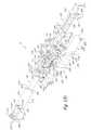
- FIGS. 2( a ) through 2 ( d )are bottom exploded perspective, top exploded perspective, bottom partially exploded, and fragmentary, partly in section, side views, respectively, of the morcellator assembly shown in FIG. 1 ;
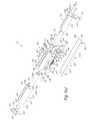
- FIGS. 3( a ) and 3 ( b )are partially exploded top perspective and partially exploded bottom perspective views, respectively, of the drive assembly shown in FIG. 1 ;
- FIGS. 4( a ) through 4 ( e )are fragmentary perspective views of alternate embodiments of the outer tubular member of the morcellator assembly of FIGS. 2( a ) through 2 ( d );
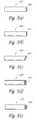
- FIGS. 5( a ) through 5 ( e )are fragmentary perspective views of alternate embodiments of the inner tubular member of the morcellator assembly of FIGS. 2( a ) through 2 ( d );
- FIG. 5( f )is a fragmentary perspective view, shown in section, of a further alternate embodiment of the inner tubular member of the morcellator assembly of FIGS. 2( a ) through 2 ( d );
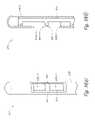
- FIGS. 6( a ) and 6 ( b )are fragmentary longitudinal section views of another embodiment of a tissue removal device constructed according to the teachings of the present invention.
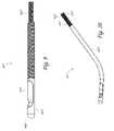
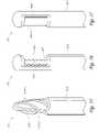
- FIGS. 7( a ) and 7 ( b )are fragmentary perspective views of a further embodiment of a tissue removal device constructed according to the teachings of the present invention.
- FIGS. 8( a ) and 8 ( b )are perspective and enlarged fragmentary perspective views, respectively, of a further embodiment of a tissue removal device constructed according to the teachings of the present invention.
- FIG. 9is a fragmentary perspective view of a further embodiment of a tissue removal device constructed according to the teachings of the present invention.
- FIG. 10is a fragmentary perspective view of a further embodiment of a tissue removal device constructed according to the teachings of the present invention.
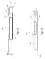
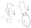
- FIG. 11is a fragmentary perspective view, broken away in part, of a further embodiment of a tissue removal device constructed according to the teachings of the present invention.
- FIG. 12is a fragmentary perspective view of a further embodiment of a tissue removal device constructed according to the teachings of the present invention.
- FIGS. 13( a ) and 13 ( b )are fragmentary perspective and fragmentary side views, respectively, of a further embodiment of a tissue removal device constructed according to the teachings of the present invention.
- FIG. 14is a fragmentary perspective view of a further embodiment of a tissue removal device constructed according to the teachings of the present invention.
- FIGS. 15( a ) and 15 ( b )are fragmentary perspective views of a further embodiment of a tissue removal device constructed according to the teachings of the present invention, the tissue removal device being shown with its cutting member in its proximal and distal positions, respectively;
- FIGS. 16( a ) and 16 ( b )are fragmentary perspective views of a further embodiment of a tissue removal device constructed according to the teachings of the present invention, the tissue removal device being shown with its movable member in its proximal and distal positions, respectively;
- FIG. 17is a fragmentary perspective view of a further embodiment of a tissue removal device constructed according to the teachings of the present invention.
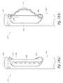
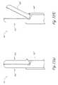
- FIGS. 18( a ) and 18 ( b )are fragmentary perspective views of a further embodiment of a tissue removal device constructed according to the teachings of the present invention, the tissue removal device being shown with its cutting element in its retracted and extended positions, respectively;
- FIGS. 19( a ) and 19 ( b )are fragmentary perspective views of a further embodiment of a tissue removal device constructed according to the teachings of the present invention, the tissue removal device being shown with its cutting element in its retracted and extended positions, respectively;
- FIG. 20is a fragmentary perspective view of a further embodiment of a tissue removal device constructed according to the teachings of the present invention.
- FIGS. 21( a ) and 21 ( b )are fragmentary perspective views of a further embodiment of a tissue removal device constructed according to the teachings of the present invention, the tissue removal device being shown with its cutting element in its distal position prior to being expanded and in its distal position after being expanded, respectively;
- FIGS. 22( a ) and 22 ( b )are fragmentary perspective views of a further embodiment of a tissue removal device constructed according to the teachings of the present invention, the tissue removal device being shown with its cutting element in closed and open positions, respectively;
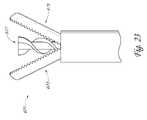
- FIG. 23is a fragmentary perspective view of a further embodiment of a tissue removal device constructed according to the teachings of the present invention.
- FIGS. 24( a ) and 24 ( b )are fragmentary perspective views of a further embodiment of a tissue removal device constructed according to the teachings of the present invention, the tissue removal device being shown with its cutting element in partially open and fully open positions, respectively;
- FIGS. 25( a ) and 24 ( b )are fragmentary perspective views of a further embodiment of a tissue removal device constructed according to the teachings of the present invention, the tissue removal device being shown with its cutting element in closed and open positions, respectively;
- FIG. 26is a fragmentary perspective view of a further embodiment of a tissue removal device constructed according to the teachings of the present invention, the tissue removal device being shown with its cutting element in its extended position;
- FIGS. 27( a ) and 27 ( b )are fragmentary perspective and fragmentary side, partly in section, views, respectively, of a further embodiment of a tissue removal device constructed according to the teachings of the present invention, the tissue removal device being shown with its cutting element in its extended position;
- FIG. 28is a fragmentary perspective view of a further embodiment of a tissue removal device constructed according to the teachings of the present invention, the tissue removal device being shown with its cutting element in its extended position;
- FIG. 29is a fragmentary perspective view of a further embodiment of a tissue removal device constructed according to the teachings of the present invention.
- FIG. 30is a fragmentary perspective view of a further embodiment of a tissue removal device constructed according to the teachings of the present invention.
- FIG. 31is a fragmentary perspective view of a further embodiment of a tissue removal device constructed according to the teachings of the present invention.
- FIG. 32is a fragmentary perspective view of a further embodiment of a tissue removal device constructed according to the teachings of the present invention.
- FIG. 33is a fragmentary perspective view of a further embodiment of a tissue removal device constructed according to the teachings of the present invention.
- FIG. 34is a fragmentary perspective view of a further embodiment of a tissue removal device constructed according to the teachings of the present invention.
- FIG. 35is a fragmentary perspective view of a further embodiment of a tissue removal device constructed according to the teachings of the present invention.
- FIG. 36is a fragmentary perspective view of a further embodiment of a tissue removal device constructed according to the teachings of the present invention.
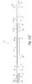
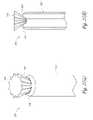
- FIG. 37is a fragmentary perspective view of a further embodiment of a tissue removal device constructed according to the teachings of the present invention.
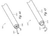
- FIGS. 38( a ) and 38 ( b )are fragmentary perspective and longitudinal section views, respectively, of a further embodiment of a tissue removal device constructed according to the teachings of the present invention.
- FIG. 39is a fragmentary perspective view of a further embodiment of a tissue removal device constructed according to the teachings of the present invention.
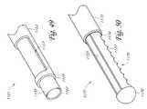
- FIGS. 40( a ) and 40 ( b )are fragmentary perspective and fragmentary side views, respectively, of a further embodiment of a tissue removal device constructed according to the teachings of the present invention.
- FIG. 41is a fragmentary perspective view of a further embodiment of a tissue removal device constructed according to the teachings of the present invention.
- FIG. 42is a fragmentary perspective view of a further embodiment of a tissue removal device constructed according to the teachings of the present invention.
- FIG. 43is a fragmentary perspective view of a further embodiment of a tissue removal device constructed according to the teachings of the present invention.
- FIG. 44is a fragmentary perspective view of a further embodiment of a tissue removal device constructed according to the teachings of the present invention.
- FIG. 45is a fragmentary perspective view of a further embodiment of a tissue removal device constructed according to the teachings of the present invention.
- FIG. 46is a fragmentary perspective view of a further embodiment of a tissue removal device constructed according to the teachings of the present invention.
- FIG. 47is a fragmentary perspective view of a further embodiment of a tissue removal device constructed according to the teachings of the present invention.
- FIG. 48is a fragmentary perspective view of a further embodiment of a tissue removal device constructed according to the teachings of the present invention.
- FIG. 49is a fragmentary perspective view of a further embodiment of a tissue removal device constructed according to the teachings of the present invention.
- FIG. 50is a fragmentary perspective view of a further embodiment of a tissue removal device constructed according to the teachings of the present invention.
- FIG. 51is a fragmentary side view of a further embodiment of a tissue removal device constructed according to the teachings of the present invention.
- FIG. 52is a fragmentary perspective view of a further embodiment of a tissue removal device constructed according to the teachings of the present invention.
- FIGS. 53( a ) and 53 ( b )are fragmentary perspective and fragmentary section views, respectively, of further embodiment of a tissue removal device constructed according to the teachings of the present invention.
- FIG. 54is a fragmentary perspective view of a further embodiment of a tissue removal device constructed according to the teachings of the present invention.
- FIG. 55reports the results of a series of experiments in which vacuum pressure and translation speed were maintained constant, and cutter rotational speeds were varied.
- FIG. 56reports data from a series of experiments in which rotational speed was maintained at a constant, vacuum pressure was maintained at a constant, and translation speeds were varied.
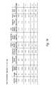
- FIG. 57reports data from a series of experiments in which rotation speed was maintained constant, translation speed was maintained constant and vacuum pressure was varied.
- the present inventionis described below primarily in the context of instruments and procedures optimized for performing one or more therapeutic or diagnostic gynecologic or urologic procedures such as the removal of uterine fibroids or other abnormal uterine tissue.
- the morcellators and related procedures of the present inventionmay be used in a wide variety of applications throughout the body, through a variety of access pathways.
- the morcellators of the present inventioncan be optimized for use via open surgery, less invasive access such as laparoscopic access, or minimally invasive procedures such as via percutaneous access.
- the devices of the present inventioncan be configured for access to a therapeutic or diagnostic site via any of the body's natural openings to accomplish access via the ears, nose, mouth, and via trans rectal, urethral and vaginal approach.
- the systems, methods, apparatus and devices of the present inventionmay be used to perform one or more additional procedures, including but not limited to access and tissue manipulation or removal from any of a variety of organs such as the bladder, lung, stomach, bowel, esophagus, oral cavity, rectum, nasal sinus, Eustachian tubes, heart, gall bladder, arteries, veins, and various ducts.
- Routes of accessinclude but are not limited to trans-cervical; trans-vaginal-wall; trans-uteral; trans-vesicle; trans-urethral; and other routes.
- FIG. 1there is shown a perspective view of one embodiment of a tissue removal system, the tissue removal system being constructed according to the teachings of the present invention and being represented generally by reference numeral 7 .
- System 7is particularly well-suited for removing uterine fibroids and other abnormal gynecological tissues. However, it should be understood that system 7 is not limited to such a use and may be used in other anatomies that may be apparent to those of ordinary skill in the art.
- System 7may comprise a tissue removal device 8 , a vacuum assembly 9 , and a control unit 10 .
- Tissue removal device 8may comprise a morcellator assembly 13 and a drive assembly 15 , morcellator 13 being removably mounted on drive assembly 15 in the manner described further below.
- Morcellator assembly 13may comprise a housing 21 .
- Housing 21which may be an elongated unitary structure made of a rigid polymer or metal, may be a generally tubular member shaped to include a proximal end 23 , a distal end 25 , and a side wall 27 .
- Side wall 27may be generally cylindrical, with a portion 28 of its bottom surface being beveled.
- a longitudinal lumen 29may extend from proximal end 23 to distal end 25 .
- An intermediate portion 31 of lumen 29may be expanded in diameter and may be accessible through an opening 33 in side wall 27 .
- a proximal portion 35 of lumen 29extending distally from proximal end 23 to a point spaced proximally from intermediate portion 31 may be expanded in diameter and may be internally threaded.
- Morcellator assembly 13may additionally comprise a pair of tubular bushings 41 and 43 .
- Bushing 41which may be a unitary structure made of a rigid polymer or metal, may be seated within intermediate portion 31 of lumen 29 , near its proximal end, and may be fixedly secured to housing 21 with screws 42 .
- Bushing 43which may be a unitary structure made of a rigid polymer or metal, may be seated within intermediate portion 31 of lumen 29 , near its distal end, and may be fixedly secured to housing 21 with screws 44 .
- Bushing 41may be shaped to include a bore 45
- bushing 43may be shaped to include a bore 47 , bores 45 and 47 being coaxially aligned with lumen 29 of housing 21 .
- Morcellator assembly 13may further comprise an elongated shaft 51 .
- Shaft 51which may be a unitary structure made of brass or another suitable rigid metal or polymer, may be shaped to include a proximal portion 53 , a distal portion 55 , an intermediate portion 57 , and a longitudinal bore 59 .
- Proximal portion 53 of shaft 51may be slidably mounted in bore 45 of bushing 41 and may be sized to freely rotate therewithin.
- Distal portion 55 of shaft 51may be slidably mounted in bore 47 of bushing 43 and may be sized to freely rotate therewithin.
- Intermediate portion 57 of shaft 51may be positioned between bushings 41 and 43 and may be in the shape of a gear having an enlarged external diameter relative to proximal portion 53 and distal portion 55 .
- Morcellator assembly 13may further comprise a translational coupling block 61 .
- Block 61which may be a unitary structure made of a rigid polymer or metal, may be a tubular member shaped to include a proximal end 63 , a distal end 64 , a side wall 65 , and a longitudinal bore 66 .
- Block 61may be coaxially mounted over proximal portion 53 of shaft 51 , with bore 66 being sized relative to proximal portion 53 so that proximal portion 53 may freely rotate within bore 66 .
- Side wall 65 of block 61may be shaped to correspond generally to the shape of intermediate portion 31 of lumen 29 . In this manner, block 61 may be kept rotationally stationary within housing 21 .
- Block 61may be translationally fixed relative to shaft 51 with a retaining ring 67 inserted coaxially over proximal portion 53 and secured to proximal portion 53 with a set screw 68 .
- a washer 69may be inserted coaxially over proximal end 53 of shaft 51 between distal end 63 of block 61 and intermediate portion 57 of shaft 51 to prevent any wear caused by contact between intermediate portion 57 against distal end 63 of block 61 as intermediate portion 57 rotates.
- Side wall 65 of block 61may further be shaped to include a waist 70 of reduced external diameter. In this manner, with block 61 coaxially mounted over proximal portion 53 of shaft 51 , a pair of slots 71 - 1 and 71 - 2 may be formed between block 61 and housing 21 .
- Morcellator assembly 13may further comprise a strain relief member 72 .
- Strain relief member 72which may be a unitary structure made of a rigid polymer or metal, may be a tubular member shaped to include a proximal portion 73 and a distal portion 74 .
- Proximal portion 73may be slightly greater in diameter than distal portion 74 and may include a bifurcating slot 75 .
- Proximal portion 73 of strain relief member 72may be disposed within the distal portion of lumen 29 , with distal portion 74 of strain relief member 72 extending distally from distal end 25 of housing 21 for a short distance, such as, for example, approximately 2 inches.
- the diameter of the outer tubular member 76can be can be increased to maximize tissue removal.
- the outer tubular member 76would have a diameter generally less than about 12 mm, preferably less than about 11 mm, and for certain applications less than 10 mm.
- morcellatorscan readily be constructed in accordance with the present invention having an outer diameter of no more than about 9 mm, in some applications less than 8 about mm, preferably less than 7 mm, and more preferably less than 6 mm where OD is desirably minimized.
- Morcellator assembly 13may further comprise a cutting mechanism.
- the cutting mechanismmay comprise an outer tubular member 76 and an inner tubular member 77 , inner tubular member 77 moving rotationally and, at the same time, oscillating translationally relative to outer tubular member 76 in the manner to be described further below.
- Outer tubular member 76which may be a unitary structure made of stainless steel or another similarly suitable material, may be shaped to include an open proximal end 79 , a closed distal end 81 , and a lumen 83 extending from open proximal end 79 to a point just prior to closed distal end 81 .
- Member 76may be coaxially mounted within strain relief member 72 , with proximal end 79 of member 76 disposed within proximal portion 73 of strain relief member 72 and with distal end 81 of member 76 extending distally beyond distal portion 74 of strain relief member 72 for an extended distance, such as, for example, five inches.
- the combination of proximal end 79 of member 76 and proximal portion 73 of strain relief member 72may be securely retained in housing 21 using a screw 85 inserted through an opening 87 in housing 21 , screw 85 pressing proximal portion 73 of strain relief member 72 tightly against proximal end 79 of member 76 .
- Outer tubular member 76may be further shaped to include a resection window 89 into which tissue may be captured and drawn, window 89 being located proximate to distal end 81 , such as, for example, 0.25 inch from distal end 81 .
- Window 89may be shaped to include a proximal end 89 - 1 and a distal end 89 - 2 .
- Proximal end 89 - 1may slope gradually proximally, and distal end 89 - 2 may slope gradually distally.
- window 89may have a length of approximately 0.55 inch
- proximal end 89 - 1may be a radial end having a radius of curvature of, for example, 0.085 inch
- distal end 89 - 2may be a radial end having a radius of curvature of, for example, 0.150 inch.
- Window 89may extend over a substantial portion of the circumference of tubular member 76 , such as, for example, about 60% of the circumference.
- Outer tubular member 76may have an outer diameter less than about 5.5 mm. However, in order to reduce the risk of injury to the patient and in order to obviate the need for anesthesia to be administered to the patient, outer tubular member 76 preferably has an outer diameter less than about 5 mm, more preferably less than 4 mm, even more preferably less than 3 mm, and still even more preferably less than 2 mm.
- Inner tubular member 77which may be an elongated unitary structure made of stainless steel or another similarly suitable material, may be shaped to include a proximal end 91 , a distal end 92 , and a longitudinal lumen 93 .
- Distal end 92may be shaped to include an external bevel, such as, for example, an external bevel of approximately 20 degrees.
- An intermediate portion of tubular member 77may be received within bore 59 of shaft 51 and may be fixedly coupled to shaft 51 for translational and rotational movement therewith using a retaining ring 94 - 1 , a slotted sleeve 94 - 2 and a pair of set screws 95 .
- proximal portion of ring 94 - 1may be screwed onto the distal end of shaft 51 , with the distal portion of ring 94 - 1 extending over member 77 .
- Sleeve 94 - 2may be inserted coaxially between member 77 and ring 94 - 1 , and set screws 95 may be inserted through a transverse opening 96 in retaining ring 94 - 1 to couple ring 94 - 1 and sleeve 94 - 2 to member 77 .
- Tubular member 77may have a suitable length so that, when tubular member 77 is in a fully retracted (i.e., proximal) position, proximal end 91 of tubular member 77 may extend proximally a short distance from proximal end 23 of housing 21 and distal end 92 of tubular member 77 may be withdrawn sufficiently to permit tissue to enter window 89 .
- tubular member 77may have a length so that, when tubular member 77 is in a fully advanced (i.e., distal) position, distal end 92 of tubular member 77 may be positioned distally of distal end 89 - 2 of window 89 .
- Morcellator assembly 13may further comprise a fitting 97 .
- Fitting 97which may be a unitary structure made of a rigid polymer or metal, may be a tubular member shaped to include a proximal portion 98 , a distal portion 99 and a longitudinal lumen 100 .
- Proximal portion 98which may be barbed, may be coupled through a length of tubing to vacuum assembly 9 .
- Distal portion 99 of fitting 97may be externally threaded for mating engagement with proximal portion 35 of housing 21 .
- Lumen 100 of fitting 97may be dimensioned to slidably receive proximal end 91 of tubular member 77 .
- An O-ring 101may be disposed within lumen 100 to provide a seal around tubular member 77 .
- Drive assembly 15may include a main body 105 .
- Main body 105which may be a unitary structure made of a rigid polymer or metal, may be a generally trough-shaped member shaped to include a distal end 107 , a proximal end 109 , and a side wall 111 .
- Distal end 107may be generally circular and may include a distal surface that includes a central portion 115 and a peripheral portion 117 .
- Central portion 115may be recessed relative to peripheral portion 117 .
- a central transverse opening 119may be provided in central portion 115 , and a pair of smaller transverse openings 120 may be provided in central portion 115 on opposite sides of central opening 119 .
- Proximal end 109may be generally circular and may include a proximal surface that includes a central portion 123 and a peripheral portion 125 . Central portion 123 may be recessed relative to peripheral portion 125 .
- a central transverse opening 127may be provided in central portion 123 , and a pair of smaller transverse openings 129 may be provided in central portion 123 on opposite sides of central opening 127 .
- Side wall 111may extend from distal end 107 to proximal end 109 but only over about the top half of their respective circumferences.
- a longitudinal groove 131may be provided along the outer surface of side wall 111 to receive a corresponding portion of housing 21 of morcellator assembly 13 .
- Groove 131may include a first transverse slot 133 extending though side wall 111 and a second transverse slot 135 extending through side wall 111 .
- First transverse slot 133may be spaced a short distance from distal end 107 and may be oriented generally circumferentially relative to side wall 111 .
- Second transverse slot 135may be spaced a short distance from proximal end 109 and from first transverse slot 133 and may be oriented generally longitudinally relative to side wall 111 .
- the inner surface of side wall 111may additionally be shaped to include a block 141 located between first transverse slot 133 and second transverse slot 135 .
- Block 141may be shaped to include an exterior groove 143 on its bottom surface, groove 143 extending parallel to second transverse slot 135 .
- a bracket 145which may be a unitary structure made of a rigid polymer or metal, may be secured to the bottom surface of block 141 with a pair of screws 146 .
- Bracket 145may be shaped to include a groove 147 on its top surface that is complementarily shaped to groove 143 , with grooves 143 and 147 jointly defining a channel of generally cylindrical shape.
- Drive assembly 15may additionally comprise a mechanism for driving rotational movement of inner tubular member 77 .
- a mechanismmay comprise a first motor 151 .
- Motor 151may comprise a first end 152 having a shaft 153 extending therefrom.
- First end 152may be received within central portion 115 of distal end 107 of body 105 and may be secured thereto with screws 156 inserted through openings 120 and into complementary openings 157 in first end 152 of motor 151 .
- shaft 153With motor 151 thus secured to distal end 107 , shaft 153 may extend through central transverse opening 119 and may freely rotate therewithin. Cables 159 may be used to connect motor 151 to control unit 10 .
- Coupling block 161which may be a unitary structure made of a rigid polymer or metal, may be shaped to include a distal base 163 and a proximal post, the proximal post extending proximally from base 163 .
- Base 163may be shaped to include a cavity 164 accessible from its distal end into which shaft 153 of motor 151 may be received and secured with a screw 165 , thereby mechanically coupling shaft 153 to block 161 .
- the proximal postmay be shaped to include a distal portion 166 of increased diameter and a proximal portion 167 of decreased diameter.
- Gear 162which may be a unitary member made of a rigid polymer or metal, may be shaped to include a distal tube 168 and a proximal toothed wheel 169 .
- Tube 168may be coaxially mounted on portion 166 of block 161 and mechanically coupled thereto with a screw 170 .
- Wheel 169may be positioned so that a portion of wheel 169 extends through slot 133 for engagement with intermediate portion 57 of shaft 51 . In this manner, rotation of wheel 169 causes the rotation of shaft 51 .
- Proximal portion 167 of post 165which may extend proximally a short distance beyond wheel 169 , may be seated within a bearing 173 , bearing 173 being seated within the distal end of the channel jointly defined by block 141 and bracket 145 .
- Drive assembly 15may further comprise a mechanism for driving oscillating translational movement of inner tubular member 77 .
- a mechanismmay comprise a second motor 181 .
- Motor 181may comprise a first end 182 having a shaft 183 extending therefrom.
- First end 182may be received within central portion 123 of proximal end 109 of body 105 and may be secured thereto with screws 186 inserted through openings 129 and into complementary openings 187 in first end 182 of motor 181 .
- shaft 183may extend through central transverse opening 127 and may freely rotate therewithin.
- a cable 189may be used to connect motor 181 to control unit 10 .
- the aforementioned mechanism for driving oscillating translational movement of inner tubular member 77may further comprise a coupling block 191 , a threaded bolt 192 , and a carriage 193 .
- Coupling block 191which may be a unitary structure made of a rigid polymer or metal, may be shaped to include a proximal opening 194 and a distal opening 195 .
- Proximal opening 194may be dimensioned to securely receive shaft 183 of motor 181 , thereby mechanically coupling shaft 183 to block 191 .
- Distal opening 195may be dimensioned to securely receive the proximal end of threaded bolt 192 , thereby mechanically coupling bolt 192 to block 191 .
- the distal end of bolt 192may be seated within a bearing 196 , which, in turn, may be seated within the proximal end of the channel jointly defined by block 141 and bracket 145 .
- Carriage 193which may be a unitary structure made of a rigid polymer or metal, may be shaped to include a bore 197 and a pair of upwardly extending tines 198 .
- a rigid collar 199may be fixedly mounted within bore 197 of carriage 193 using a pair of screws 200 .
- Collar 199may be internally threaded to engage bolt 192 .
- Carriage 193may be mechanically coupled for translational movement to shaft 51 by tines 198 , with tines 198 extending through slot 135 of body 105 and being received within slots 71 - 1 and 71 - 2 of morcellator assembly 13 .
- the speed at which inner tubular member 77 rotates and the speed at which inner tubular member 77 oscillates translationallyare separately and independently controlled, with the rotation of inner tubular member 77 being controlled by motor 151 and with the oscillating translation of inner tubular member 77 being controlled by motor 181 .
- Body 201which may be a unitary structure made of a rigid polymer or metal, may be shaped to include a distal end 203 , a proximal end 205 , a side wall 207 , and a cavity 208 .
- Distal end 203may be generally semi-circular in shape
- proximal end 205may be generally semi-annular in shape.
- Side wall 207may be semi-annular in transverse cross-section and may extend from distal end 203 to proximal end 205 .
- a longitudinal groove 209may be provided along the top, outer surface of side wall 207 to receive a corresponding portion of housing 21 of morcellator assembly 13 .
- Cavity 208may be dimensioned to receive motor 151 .
- a pair of longitudinal lumens 213may be provided in body 201 , lumens 213 extending through distal end 203 , proximal end 205 , and side wall 207 . Lumens 213 may be aligned with corresponding threaded cavities 215 in body 105 so that proximal end 205 of body 201 and may be fixed to distal end 107 of body 105 using screws 217 inserted through body 201 and into cavities 215 .
- Locking clip 221which may be a unitary structure made of a rigid polymer or metal, may be shaped to include a base 223 , a pair of parallel legs 225 , and a pair of parallel feet 227 .
- Legs 225may extend upwardly from base 223 , with legs 225 being spaced inwardly a short distance from the ends of base 223 .
- Feet 227may extend transversely from legs 225 .
- Base 223may be received within a matingly-shaped recess 229 provided on body 105 and may be securely retained within recess 229 by securing body 201 to body 105 .
- legs 225extend upwardly beyond body 105 and may be inserted into corresponding L-shaped slots 230 in housing 21 of morcellator assembly 13 .
- clip 221may be used to reversibly and lockably couple drive assembly 15 to morcellator assembly 13 . More specifically, to lockably couple drive assembly 15 to morcellator assembly 13 , one may insert feet 227 into the proximal portions 230 - 1 of slots 230 and may then slide feet 227 distally to the distal portions 230 - 2 of slots 230 . To uncouple drive assembly 15 from morcellator 13 , feet 227 may be slid proximally from distal portions 230 - 2 to proximal portions 230 - 1 and may then be removed from slots 230 .
- Body 231which may be a unitary structure made of a rigid polymer or metal, may be a generally cylindrical member shaped to include a proximal end 233 , a distal end 235 , and a side wall 237 .
- a cavity 239may extend proximally from distal end 235 , cavity 239 being dimensioned to receive substantially all but first end 182 and shaft 183 of motor 181 .
- a pair of longitudinal lumens 241may be provided in body 231 , lumens 241 extending through proximal end 233 , distal end 235 , and side wall 237 .
- Lumens 241may be aligned with corresponding threaded cavities 242 in body 105 so that distal end 235 of body 231 may be fixed to proximal end 109 of body 105 using screws 243 inserted through body 231 and into cavities 242 .
- a groove 245may extend longitudinally from proximal end 233 to distal end 235 along the top surface of side wall 237 . Groove 245 may be aligned with groove 131 of body 105 in order to receive a corresponding portion of housing 21 of morcellator assembly 13 .
- Endplate 251may be a unitary structure made of a rigid polymer or metal, may be a generally disc-shaped structure shaped to include a retaining loop 253 at its top. Retaining loop 253 may be dimensioned to receive the proximal end of housing 21 of morcellator assembly 13 .
- a pair of openings 255may be provided in endplate 251 . Openings 255 may be aligned with corresponding threaded cavities 257 in body 231 so that endplate 241 may be fixed to proximal end 233 of body 231 using screws 259 inserted through endplate 241 and into cavities 257 .
- Cover 261may be a unitary structure made of a rigid polymer or metal, may be in the shape of a half-pipe having a proximal end 263 and a distal end 265 . Cover 261 may be dimensioned to complement side walls 111 and 207 of bodies 105 and 201 , respectively.
- cover 261may be fixed to body 105 with a screw 267 inserted through an opening 269 in cover 261 and into a corresponding cavity 271 in proximal end 109 of body 105 and with a screw 273 inserted through an opening 275 in cover 261 and into a corresponding cavity 277 in distal end 107 of body 105 .
- cover 261may be fixed to body 201 by joining cover 261 to a block 281 using a screw 283 and by joining block 281 to distal end 203 of body 201 using a pair of screws 285 .
- vacuum assembly 9may include a specimen collection container 291 and a vacuum source 292 .
- the distal end of an evacuation tube 293may be inserted over fitting 97 and may be secured thereto by a friction fit, and the proximal end of evacuation tube 293 may be coupled to a first port 294 of container 291 .
- the distal end of a tube 295may be coupled to a second port 296 of container 291 , and the proximal end of tube 295 may be coupled to vacuum source 292 .
- vacuum source 292may be used to apply suction to device 8 , and any withdrawn tissue, liquids or similar matter suctioned through device 8 may be collected in container 291 .
- Control unit 10which may be coupled to a source of electricity, such as an AC wall outlet, using a power cord (not shown), may include electronics (not shown) for controlling the operation of motors 151 and 181 using a cable 298 - 1 connected to cables 159 and 189 .
- a foot pedal 297may be coupled to control unit 10 by a cable 298 - 2 and may be used as a power switch to selectively activate or de-activate motors 151 and 181 .
- Control unit 10may further include a vacuum sensor 299 , which may be coupled to container 291 by a tube 300 , so that the pressure within container 291 may be monitored by control unit 10 . In this manner, a sudden increase in vacuum pressure may indicate that a clog has occurred.
- Control unit 10may be configured to synchronize actuation of drive assembly 15 with actuation of vacuum source 292 . In this manner, turning on drive assembly 15 will turn on vacuum source 292 at the same time. Correspondingly, vacuum source 292 may be deactivated whenever drive assembly 15 is turned off.
- the distal end of a hysteroscopemay be inserted transcervically into a patient, and a suitable fluid may be conducted through the inlet fluid port of the hysteroscope into the uterus until the uterus is distended. Observation of the uterus and detection of fibroids or other abnormal gynecological tissues may then be performed using the visualization channel of the hysteroscope.
- the distal ends of outer tubular member 76 and inner tubular member 77may be inserted through a working channel of the hysteroscope and into the uterus, with the remainder of system 7 remaining proximal to the hysteroscope.
- Device 8may then be manipulated so that window 89 of outer tubular member 76 may be positioned in proximity to the fibroid or other targeted tissue.
- vacuum source 292may be operated so as to cause suction to be applied to inner tubular member 77 , thereby drawing tissue into outer tubular member 76 through window 89 .
- motors 151 and 181may be operated so as to cause inner tubular member 77 simultaneously to rotate and to oscillate back and forth translationally within outer tubular member 76 , thereby causing the tissue drawn through window 89 to be cut.
- the cut tissuemay then be suctioned from the patient through inner tubular member 77 by means of the aforementioned suction and, thereafter, collected in container 291 .
- vacuum source 292 and motors 151 and 181may be turned off, device 8 may be withdrawn from the hysteroscope, and the hysteroscope may be withdrawn from the patient.
- Morcellator assembly 13may then be detached from drive assembly 15 and disconnected from vacuum source 292 .
- Morcellator assembly 13may be designed to be a single use device and, if so, may be disposed of after being used on a patient.
- drive assembly 15may be used on a number of different patients prior to its disposal, with a different morcellator assembly 13 preferably being used with each patient.
- fluidmay be administered transcervically to the uterus by a fluid dispensing device in order to distend the uterus, and, thereafter, observation of the uterus may be accomplished, for example, by ultrasonic imaging using an ultrasonic probe inserted transcervically into the uterus.
- ultrasonic imagingmay be separate from device 8 or may be integrated into device 8 .
- imaging of the uterusmay be performed by MRI imaging.
- speed of rotational movement of inner tubular member 77at least 1100 rpm, more preferably at least 5000 rpm, even more preferably approximately 6000 rpm; frequency of oscillating translational movement of tubular member 77 —at least 1.5 cycles/second, more preferably at least 2.5 cycles/second, even more preferably about 4 cycles/second; advance ratio of preferably less than 0.25, more preferably less than 0.15; and vacuum pressures in the range of 300 to 650 mmHg.
- the above parametersare selected to achieve a rate of tissue removal of at least 1.5 gm
- system 7is constructed and operated so that, with a vacuum in excess of 300 mmHg, a volume of no more than about 300 cc/min of fluid is removed. This may involve, for example, applying suction only at specific times, for example, when motors 151 and 181 are actuated.
- morcellatorsmay be built in accordance with the present invention to have a lower outside diameter or crossing profile than current commercial products such as the Smith & Nephew Hysteroscopic Morcellator, but at the same time accomplish a higher tissue resection rate.
- morcellators in accordance with the present inventionmay be operated at a significantly higher vacuum while managing total fluid flow within acceptable limits.
- the cross sectional area of the aspiration lumen in morcellators in accordance with the present inventionwill typically be no more than about 12.0 square millimeters, and often nor more than about 10.0 square millimeters.
- a cross sectional area of the aspiration lumenwill be no more than about 8.0 millimeters squared, and, for certain applications, the area will be no more than about 7.5 square millimeters.
- the tissue resection rateis generally at least about 1.5 gm/min, and often at least about 1.8 gm/min. In certain embodiments, the tissue resection rate is at least about 2.0 gm/min, and, in one embodiment, 2.2 or more gm/min.
- morcellators in accordance with the present inventionmay be constructed to have a fluid usage of no more than about 350 ml/min. In many embodiments, fluid usage of no more than about 300 ml/min or no more than about 275 ml/min may be constructed.
- Applied vacuum to the morcellators of the present inventionwill generally be in the range of from about 200 to about 800 mm Hg.
- the morcellatorwill typically be run at a vacuum of at least about 350 mm Hg, and, often at least about 500 mm Hg.
- the cross sectional area of the aspiration lumenwas about 7.1 mm 2 , and yielded a tissue resection rate of about 1.4 gm/min, under vacuum of approximately 600 mm Hg.
- procedures accomplished in accordance with the present inventionwill require no more than about 10 minutes, and preferably, no more than about 8 or 9 minutes of active morcellation.
- total fluide.g. saline
- Distension fluidwill preferably be maintained at a low enough pressure and short enough time to keep the total saline intravasation below 2.5 liters.
- the fluid flow rate for aspiration of saline through the morcellatoris approximately 260 ml/min (e.g. within the range of from about 240 to about 280 ml/min).
- the tissue resection rateis typically in excess of about 2 gm/min.
- a device manufactured in accordance with the present inventionwas compared to the performance of a reciprocating hysteroscopic morcellator, from Smith and Nephew.
- the vacuumwas maintained on average in the 200 to 270 mm Hg range
- morcellator speedwas approximately 1100 rpm
- tissue resection ratewas approximately 1.4 gm/min
- the fluid flow rate through the morcellatorwas approximately 247 ml/min
- the outside diameter of the morcellatorwas 4.0 mm.
- the device constructed in accordance with the present inventionwas operated at a vacuum of 600 mm Hg, a speed of about 6000 rpm, to produce a resection rate of approximately 2.2 gm/min and an aspiration flow rate of about 266 ml/min through the morcellator.
- the outside diameter of the devicewas 3 mm.
- the morcellator in accordance with the present inventionthus produced a significantly higher resection rate, through a smaller outside diameter morcellator, at a roughly comparable flow rate of aspirated saline.
- the vacuumIn order to increase the resection rate of the predicate device, the vacuum must be significantly increased. For example, when the vacuum pressure in the predicate system was increased to about 670 mm Hg, the tissue cutting improved to 3.5 gm/min but fluid flow rate jumped to 540 ml/min.
- system 7may further include means for providing an audible indication to the user that motors 151 and/or 181 are being operated.
- an audible indicationmay be provided by a current detector coupled both to motors 151 and/or 181 and to an audible signal generator, wherein the signal generator may emit a beeping tone or other sound to indicate that motors 151 and/or 181 are in use.
- an audible indication that motor 151 is in usemay be provided by an interference nub provided, for example, on distal tube 168 of gear 162 , said interference nub being engageable with a pivotally-mounted flipper arm so that rotation of tube 168 may cause vibration of the flipper arm.
- a sound chamberis provided in such a device to magnify the vibrations of the flipper arm to provide an audible sound.
- the audible soundwill preferably be greater than about 500 Hz in frequency and less than about 10,000 Hz so that its tone may be easily recognized.
- system 7may further include a current flow sensor for monitoring the electrical current required to operate motors 151 and/or 181 . If a sudden change in current level is detected, for example, in the case of over-torque and under-torque conditions, respectively, a switch linked to the current flow sensor may be opened to shut down motors 151 and 181 .
- the additional safety of controlling motor operation by detecting an unusual operating conditionmay enhance patient safety by informing the operator that the device was operating in an unsafe mode and should be inspected to ensure that no damage has occurred.
- the current detection capabilitywill preferably suspend the motor operation should current drop below 10% or exceed 150% of its steady state operating value.
- system 7may further include a timer that may be linked to the operation of motors 151 and/or 181 to provide a running total of the operating time of the tissue removal device.
- the timermay be reset each time drive assembly 15 is restarted to provide the running time for the current operation.
- the devicemay inform the user of the elapsed procedure time, thereby enabling the user to make judgments on the safety of continuing the procedure. This information may be valuable since, in many procedures, anesthesia or fluid intravasation limits are directly related to the operating time. Thus, recognition of the elapsed time will enable the user to terminate the procedure should the appropriate time limitation be reached.
- sensor 299may be replaced with a flow sensor, such as an ultrasonic or laser transducer that can detect a change in the flow rate of fluid through the evacuation tube 293 , whereby a sudden drop in fluid flow results in a change in signal properties from the transducer.
- a sensormay be used that comprises a scale that can detect the change in the weight of matter collected in specimen container 291 , with a plateauing of weight indicating that flow has stopped.
- the presence of a clogmay be indicated via an alarm, which may be an audible alarm and/or a visible alarm, e.g., a flashing LED.
- the audible alarmmay comprise a chamber in fluid communication with vacuum source 292 wherein a change in pressure level or flow creates a pressure gradient strong enough to create a whistle or audible sound through the chamber.
- device 8may be modified so that outer tubular member 76 may be angularly adjustable about its longitudinal axis relative to housing 21 . This may be accomplished by fixedly mounting outer tubular member 76 on a hub that is rotatably mounted on housing 21 . In this manner, outer tubular member 76 may be angularly adjusted so that resection window 89 may be positioned at a desired angular position. Preferably, means are provided to prevent the rotatable hub from freely spinning while the device is being used to resect tissue.
- resection window 89 of outer tubular member 76 and distal end 92 of inner tubular member 77are described above as possessing certain dimensions and/or geometries, the present invention is not limited to such dimensions and geometries and may encompass alternate dimensions and/or geometries.
- the geometry of resection window 89may be varied from a straight perpendicular edge to a more complicated parabolic profile.
- Two underlying principlesguide the selection of the geometry. First, structural loading considerations will favor the use of gussets in the corners of the window to alleviate the stress concentrations observed at sharp corners under operating loads. Second, the highest bite efficiency will be obtained with the largest possible window opening.
- bit efficiencyrefers to the amount of material or tissue that can be removed with each stroke of a cutting edge.
- rhorefers to the ratio of conic section lengths used to define the curvature of a parabolic shape.
- the optimum value for rho for this applicationis preferably greater than 0.414, which defines a circle, and less than 1, which describes a perpendicular straight edge.
- Radial ends of the windowtend to engage subject tissues whose growth produces cylindrical or spherical entities far more effectively than conventional squared ends.
- the radial endsenhance the device's ability to create a vacuum seal against the tissue that enables a larger specimen to be drawn into the cutting window.
- the resulting larger specimensimprove the bite efficiency whereby the largest possible specimens are captured each time the inner cutter is activated. High bite efficiency translates into reduced procedure time and the potential for complications associated with anesthesia, intravasation, etc.
- the resection windowpreferably extends over approximately 30% to 80% of the circumference of the outer tube, i.e., “the open ratio.”
- the open ratiowill define combinations of inner tubes and outer tubes whereby the tissue specimen size is comparable to that of the tube opening.
- FIGS. 4( a ) through 4 ( e )there are shown various fragmentary, perspective views of alternate embodiments to outer tubular member 76 , the alternate outer tubular members being represented generally by reference numerals 301 , 302 , 303 , 304 and 305 , respectively.
- Members 301 , 302 , 303 , 304 and 305are similar in most respects to outer tubular member 76 and may be used in place thereof, the principal differences among the various members being in the size, shape and/or placement of their respective windows. More specifically, member 301 ( FIG. 4( a )) may comprise a window 307 having a parabolic shape. Members 302 ( FIG. 4( b )) and 303 ( FIG.
- Member 4( c ))may comprise rectangularly-shaped windows 308 and 309 , respectively, with window 309 differing from window 308 in that window 309 has a greater open ratio than window 308 and in that window 308 is positioned closer to distal end 302 - 1 of member 302 than window 309 is to distal end 303 - 1 of member 303 .
- Member 304( FIG. 4( d )) may comprise a window 310 having a sloped proximal end 310 - 1 and a jagged distal end 310 - 2 .
- Member 305( FIG. 4( e )) may comprise a window 311 having a straight proximal end 311 - 1 and a distal end 311 - 2 having a proximally-directed point 312 .
- FIGS. 5( a ) through 5 ( e )there are shown various fragmentary, perspective views of alternate embodiments to inner tubular member 77 , the alternate inner tubular members being represented generally by reference numerals 321 , 322 , 323 , 324 and 325 , respectively.
- Members 321 , 322 , 323 , 324 and 325are similar in most respects to inner tubular member 77 and may be used in place thereof, the principal difference among the various members being in the shape of their respective distal ends. More specifically, member 321 ( FIG. 5( a )) may comprise a distal end 326 having a rectangular shape with a 30 degree external bevel.
- Member 322( FIG.
- 5( b ))may comprise a distal end 327 having a rectangular shape with an internal bevel.
- Member 323( FIG. 5( c )) may comprise a distal end 328 having an angled shape with an external bevel.
- Member 324( FIG. 5( d )) may comprise a jagged distal end 329 having eight teeth.
- Member 325( FIG. 5( e )) may comprise a jagged distal end 330 having six teeth.
- Inner tubular member 331may be similar in most respects to inner tubular member 77 , with inner tubular member 331 differing principally from inner tubular member 77 in that inner tubular member 331 may comprise a proximal portion 333 of comparatively greater inner diameter and a distal portion 335 of comparatively lesser inner diameter.
- the expanded inner diameter of proximal portion 333may permit matter to be drawn proximally through inner tubular member 331 with greater ease, thereby reducing the risk that inner tubular member 331 may become clogged.
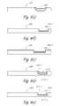
- FIGS. 6( a ) and 6 ( b )there are shown fragmentary longitudinal section views of another embodiment of a tissue removal device constructed according to the teachings of the present invention, said tissue removal device being represented by reference numeral 341 .
- Device 341may be similar in most respects to device 8 , device 341 differing principally from device 8 in that device 341 may comprise an inner tubular member 342 , an outer tubular member 343 , and a plug 344 , instead of outer tubular member 76 and inner tubular member 77 .
- Inner tubular member 342may be identical to inner tubular member 77 .
- Outer tubular member 343may be similar in most respects to outer tubular member 76 , with outer tubular member 343 differing principally from outer tubular member 76 in that outer tubular member 343 may comprise an open distal end 345 .
- Plug 344which may be fixedly mounted within distal end 345 of outer tubular member 343 , may be shaped to include a mandrel 346 .
- Mandrel 346may extend proximally within lumen 347 of outer tubular member 343 , terminating distally prior to window 348 .
- Window 348may have the same dimensions and geometry as window 89 of outer tubular member 76 .
- Mandrel 346may be dimensioned so that, when inner tubular member 342 is moved distally, distal end 349 of inner tubular member 342 may slide past the side wall 346 - 1 of mandrel 346 , thereby shearing tissue located therebetween.
- mandrel 346serves to push tissue down the lumen of inner tubular member 342 to ensure that the tissue is severed and that vacuum pressure can draw the tissue through inner tubular member 342 .
- mandrel 346may be shaped to include a longitudinal bore 350 aligned with the lumen 342 - 1 of inner tubular member 342 . Bore 350 may serve to permit fluid to enter inner tubular member 342 —even when inner tubular member 342 is in its most distal position.
- tissue and other mattermay be moved proximally through inner tubular member 342 by such fluid flow, thereby preventing inner tubular member 342 from becoming clogged.
- tissue and other mattermay be moved proximally through inner tubular member 342 by such fluid flow, thereby preventing inner tubular member 342 from becoming clogged.
- FIGS. 7( a ) and 7 ( b )there are shown fragmentary perspective views of a further embodiment of a tissue removal device constructed according to the teachings of the present invention, said tissue removal device being represented by reference numeral 351 .
- Device 351may be similar in most respects to device 8 , device 351 differing principally from device 8 in that device 351 may comprise an outer tubular member 352 and an inner tubular member 353 .
- Outer tubular member 352which may be similar in certain respects to outer tubular member 76 of device 8 , may comprise a distal end 355 having an external bevel.
- Inner tubular member 353which may be similar in certain respects to inner tubular member 77 , may comprise a closed distal end 357 having a dome-shape and a resection window 359 spaced proximally a short distance in front of distal end 357 .
- Window 359may be shaped to comprise a sharpened distal end 360 .
- outer tubular member 352may be stationary, and inner tubular member 353 may rotate relative to the longitudinal axis of outer tubular member 352 and, at the same time, may oscillate translationally in an independently controllable fashion between a distal position in which window 359 is positioned distally beyond outer tubular member 352 and a proximal position in which window 359 is positioned within outer tubular member 352 .
- inner tubular member 353may oscillate translationally without rotating.
- window 359may be drawn proximally into outer tubular member 352 , the tissue that has entered window 359 may be cut between distal end 360 of window 359 and distal end 355 of outer tubular member 352 .
- the tissueBy shearing the tissue on the proximal stroke of inner tubular member 353 , the tissue may be pushed down the lumen of inner tubular member 353 in the same direction that suction is being applied.
- the additional mechanical force provided by this cutting actionmay reduce the risk of clogging inner tubular member 353 .
- Such a reduction in the risk of cloggingmay enhance the likelihood that the procedure may be completed as planned and reduce the need for follow-up procedures or delayed or canceled procedures.
- FIGS. 8( a ) and 8 ( b )there are shown perspective and enlarged fragmentary perspective views, respectively, of a further embodiment of a tissue removal device constructed according to the teachings of the present invention, said tissue removal device being represented generally by reference numeral 381 .
- Tissue removal device 381may be similar in many respects to device 8 . However, one notable difference between the two devices may be that, whereas device 8 may comprise a cutting mechanism including outer tubular member 76 and inner tubular member 77 , both of which may be straight, device 381 may comprise a cutting mechanism including an outer tubular member 383 and an inner tubular member 385 , wherein outer tubular member 383 may include a bent region 387 and inner tubular member 385 may contain a corresponding compliant section 389 . Outer tubular member 383 may be formed into the desired configuration using conventional tooling to provide a fixed bent angle. Alternatively, one may furnish the user with a forming tool that allows the user to form the outer tubular member into any desired angle to ease delivery of the device.
- the inner tubular member 385may include a flexible drive shaft 391 located in the bent region.
- Flexible drive shaft 391may be directed around the bent region 387 to transmit torque and translational motion.
- the angled tipmay also make direction of the cutting tip easier to direct, especially when trying to access the fallopian regions of the uterus.
- the tipmay be rotated by rotating the entire device, or the device may be provided with a rotation knob 392 to permit the cutting mechanism to be rotated relative to the drive assembly.
- any reduction in the time required to direct the device towards the target pathologymay reduce overall procedure duration and increase the probability of successful removal of the entire tissue specimen.
- FIG. 9there is shown a fragmentary perspective view of a further embodiment of a tissue removal device constructed according to the teachings of the present invention, said tissue removal device being represented generally by reference numeral 401 .
- Tissue removal device 401may be similar in many respects to device 8 . However, one notable difference between the two devices may be that, whereas device 8 may comprise a cutting mechanism including outer tubular member 76 and inner tubular member 77 , both of which may be straight and axially inflexible, device 401 may comprise a cutting mechanism including an outer tube having some axial flexibility and an inner tube having some axial flexibility, the inner tube being independently rotatable and translationally oscillatable within the outer tube.
- the outer tubemay comprise an axially flexible tubular shaft 403 and a rigid tubular tip 405 , tip 405 being fixed to the distal end of shaft 403 .
- the inner tubemay comprise an axially flexible tubular shaft 407 and a rigid tubular tip 409 , tip 409 being fixed to the distal end of shaft 407 .
- Tubular tip 405may have a shape similar to the distal portion of outer tubular member 76 so that shaft 403 and tip 405 may collectively have a shape corresponding generally to that of outer tubular member 76 .
- Tubular tip 409may have a shape similar to the distal end of inner tubular member 77 so that shaft 407 and tip 409 may collectively have a shape corresponding generally to that of inner tubular member 77 .
- Each of shaft 403 and shaft 407may be made of a suitable metal, such as Nitinol (nickel-titanium alloy) or Microflex hypo tubing, or may be made of a suitable polymeric material, such as TEFLON® polytetrafluoroethylene, polyamide, polyimide, polyetheretherketones etc.
- a suitable metalsuch as Nitinol (nickel-titanium alloy) or Microflex hypo tubing
- a suitable polymeric materialsuch as TEFLON® polytetrafluoroethylene, polyamide, polyimide, polyetheretherketones etc.
- device 401may provide a cutting mechanism that more closely mimics the access angles of the body in places like the bladder, cervix and uterus.
- the ability to flexmay reduce introduction forces and may reduce the probability of a perforation.
- any reduction in the time required to direct the cutting mechanism towards the target pathologymay reduce overall procedure duration and increase the probability of successful removal of the entire targeted tissue.
- FIG. 10there is shown a fragmentary perspective view of a further embodiment of a tissue removal device constructed according to the teachings of the present invention, said tissue removal device being represented generally by reference numeral 421 .
- Device 421may be similar in many respects to device 401 , device 421 differing principally from device 401 in that device 421 may additionally comprise a pair of pull wires 422 and 423 .
- Pull wires 422 and 423which may be used to flex shaft 403 at a desired angle, may be fixed at their respective distal ends to shaft 403 and may be fixed at their respective proximal ends to a spring-torsioned, rotatable hub (not shown). Because of its own flexibility, shaft 407 will bend to accommodate the deflection of shaft 403 .
- FIG. 11there is shown a fragmentary perspective view, broken away in part, of a further embodiment of a tissue removal device constructed according to the teachings of the present invention, said tissue removal device being represented generally by reference numeral 430 .
- Device 430may be similar in many respects to device 8 , device 430 differing principally from device 8 in that device 430 may include, instead of outer tubular member 76 and inner tubular member 77 , an inner tubular member 431 , an outer tubular member 432 , and a plug 433 .
- Inner tubular member 431may be identical to inner tubular member 331 .
- Outer tubular member 432may be similar to outer tubular member 76 , except that outer tubular member 432 may include an open distal end.
- Plug 433which may be a solid member fixed to outer tubular member 432 , may include a proximal portion 435 of cylindrical shape snugly disposed within the lumen of outer tubular member 432 and a distal portion 437 of rounded shape extending distally from the distal end of outer tubular member 432 .
- Proximal portion 435may have a proximal surface 439 that is positioned to contact the distal end of inner tubular member 431 when inner tubular member 431 completes its distal stroke.
- Inner tubular member 431may oscillate translationally or may rotate and oscillate translationally in an independently controllable fashion.
- inner tubular member 431In use, as inner tubular member 431 moves distally, the distal end of inner tubular member 431 engages tissue that may have entered window 440 . When inner tubular member 431 reaches the end of its distal stroke, the distal end of inner tubular member 431 strikes proximal surface 439 of plug 433 . This striking or chopping action of the distal end of inner tubular member 431 against proximal surface 439 creates a shear plane that results in tissue fibers and tags not being left behind when inner tubular member 431 thereafter moves through its proximal stroke. In this manner, the distal end of inner tubular member 431 and proximal surface 439 of plug 433 ensure that a clean cut is achieved.
- the risk for cloggingmay be minimized and the need for multiple strokes to cut the tissue may be reduced. Both of these benefits may improve the cutting efficiency, which, in turn, may greatly enhance the likelihood that the procedure may be completed as planned and may reduce the need for follow-up procedures or delayed or canceled procedures.
- FIG. 12there is shown a fragmentary, perspective view of a further embodiment of a tissue removal device constructed according to the teachings of the present invention, said tissue removal device being represented by reference numeral 451 .
- Device 451may be similar in many respects to device 430 , with device 451 differing principally from device 430 in that device 451 may comprise an outer tubular member 453 and an electrocautery tip 455 , instead of outer tubular member 432 and plug 433 .
- Outer tubular member 453may be similar to outer tubular member 432 , except that outer tubular member 453 may be further provided with electrical leads 457 running through side wall 459 to couple tip 455 to a power source (not shown).
- Tip 455which may be heated by current passing through leads 457 , may be used to cauterize small arterial vessel bleeding that may incidentally occur while using device 451 to resect tissue. By minimizing such bleeding, tip 455 reduces the amount of blood that may fill the uterus and that may create visualization or blood loss concerns.
- FIGS. 13( a ) and 13 ( b )there are shown fragmentary perspective and fragmentary side views, respectively, of a further embodiment of a tissue removal device constructed according to the teachings of the present invention, said tissue removal device being represented by reference numeral 471 .
- Device 471may be similar in certain respects to device 8 , with device 471 differing principally from device 8 in that device 471 may comprise a tubular member 473 , instead of the combination of outer tubular member 76 and inner tubular member 77 .
- Tubular member 473may be similar in certain respects to outer tubular member 76 , with tubular member 473 differing from outer tubular member 76 in that tubular member 473 may comprise a longitudinally-extending lumen 475 provided in a side wall 477 .
- the proximal end (not shown) of lumen 475may be optically coupled to the output end of a laser (not shown) so that laser light 479 may be transmitted distally across a resection window 480 provided in side wall 477 , laser light 479 being capable of tissue resection.
- the proximal end (not shown) of tubular member 473may be coupled to vacuum source 292 so that suction may be used to draw tissue through window 480 , where it may be cut by laser light 479 , and then to move the cut tissue proximally through tubular member 473 .
- FIG. 14there is shown a fragmentary perspective view of a further embodiment of a tissue removal device constructed according to the teachings of the present invention, the tissue removal device being represented generally by reference numeral 490 .
- Device 490may be similar in most respects to device 471 , with device 490 differing from device 471 in that device 490 may include a lumen 492 having a horseshoe-shape in transverse cross-section and in that device 490 may further include an optic fiber 494 positioned within lumen 492 for transmitting the laser light.
- Optic fiber 494may be adapted to move back and forth between ends 496 and 498 of lumen 492 to provide a knife-like cutting action for tissue within window 497 .
- Optic fiber 494may be moved along the desired cutting arc within lumen 492 by coupling the proximal end (not shown) of fiber 494 to an articulating rotating cylinder or tube.
- FIGS. 15( a ) and 15 ( b )there are shown fragmentary perspective views of a further embodiment of a tissue removal device constructed according to the teachings of the present invention, the tissue removal device being represented generally by reference numeral 501 .
- Device 501may be similar in certain respects to device 351 , with device 501 differing principally from device 351 in that device 501 may comprise the combination of an outer tubular member 503 and an inner cutting member 505 , instead of the combination of outer tubular member 352 and inner tubular member 353 .
- Outer tubular member 503may be similar in most respects to outer tubular member 352 , with outer tubular member 503 differing principally from outer tubular member 352 in that outer tubular member 503 may include a distal end 507 that is straight, as opposed to beveled.
- Inner cutting member 505may comprise a plurality of outwardly biasing blades 509 fixed at their respective distal ends to a cap 511 so that inner cutting member 505 assumes a whisk-like structure when extended distally relative to outer member 503 .
- Blades 509 and cap 511may include an electrically-conductive material so that, by electrically coupling the proximal ends (not shown) of blades 509 to a suitable electrical power source (not shown), blades 509 and/or cap 511 may be used for electrocautery.
- device 501may be delivered transcervically to the uterus, preferably through the working channel of a hysteroscope, with inner cutting member 505 in its proximal position, i.e., with cap 511 against distal end 507 of outer tubular member 503 ( FIG. 15( a )). While in this state, electricity may be transmitted to cap 511 so that cap 511 may be used to burn the tissue of interest. Alternatively, inner cutting member 505 may be moved distally relative to outer tubular member 503 to its extended position ( FIG. 15( b )).
- inner cutting member 505may be rotated about its longitudinal axis so that blades 509 may cut tissue. Simultaneously, electricity may be transmitted to blades 509 and cap 511 for cauterization. Suction may be applied to the proximal end (not shown) of outer tubular member 503 to draw tissue into contact with blades 509 and to move resected tissue proximally through tubular member 503 .
- FIGS. 16( a ) and 16 ( b )there are shown fragmentary perspective views of a further embodiment of a tissue removal device constructed according to the teachings of the present invention, the tissue removal device being represented generally by reference numeral 521 .
- Device 521may be similar in certain respects to device 501 , with device 521 differing principally from device 501 in that device 521 may comprise the combination of a tubular member 523 and an outwardly-biasing loop 525 slidably mounted in tubular member 523 , instead of the combination of outer tubular member 503 and inner cutting member 505 .
- device 521may be delivered transcervically to the uterus, preferably through the working channel of a hysteroscope, with loop 525 in its proximal or retracted position within tubular member 523 ( FIG. 16( a )). Next, loop 525 may be moved distally relative to tubular member 523 , thereby allowing loop 525 to expand ( FIG.
- loop 525With loop 525 thus expanded, loop 525 may be placed around the tissue of interest. Loop 525 may then be withdrawn into tubular member 523 , with loop 525 drawing the surrounded tissue into tubular member 523 . (If desired, loop 525 may also be made to be rotatable about the longitudinal axis of tubular member 523 .) As the tissue is drawn past the distal end 527 of tubular member 523 by loop 525 , the tissue is severed. Suction may be applied to the proximal end (not shown) of tubular member 523 to draw tissue into loop 525 and to move resected tissue proximally through tubular member 523 .
- Loop 525may include electrically-conductive material and may be electrically coupled to an electrical power source for use in electrocautery.
- device 521may be modified to include a second loop, the two loops having opposite polarities to provide a bipolar electrocautery device.
- An advantage of a bipolar device, as opposed to a monopolar device,is that a bipolar device may be used with an electrically-conductive distension fluid, such as saline.
- FIG. 17there is shown a fragmentary perspective view of a further embodiment of a tissue removal device constructed according to the teachings of the present invention, the tissue removal device being represented generally by reference numeral 541 .
- Device 541may be similar in certain respects to device 521 , with device 541 differing principally from device 521 in that device 541 may comprise the combination of a tubular member 543 and a grappling assembly 545 slidably mounted in tubular member 543 , instead of the combination of tubular member 523 and loop 525 .
- Grappling assembly 545may comprise a rotatable shaft 547 , a cap 549 mounted on the distal end of shaft 547 , a plurality of fingers 551 extending downwardly at an angle from cap 549 , an auger 553 coaxially inserted over and mechanically coupled to shaft 547 , and a plurality of fingers 555 extending upwardly at an angle from auger 553 .
- device 541may be delivered transcervically to the uterus, preferably through the working channel of a hysteroscope, with assembly 545 in its proximal or retracted position within tubular member 543 , i.e., with cap 549 against the distal end 544 of tubular member 543 .
- assembly 545may be moved distally relative to tubular member 543 , and shaft 547 may be rotated. Fingers 551 and 555 may grab the tissue of interest, and assembly 545 may be retracted into tubular member 543 . As the tissue is drawn past the distal end 544 of tubular member 543 , the tissue is severed.
- Suctionmay be applied to the proximal end (not shown) of tubular member 543 to draw tissue towards fingers 551 and 555 and to move resected tissue proximally through tubular member 543 .
- auger 553may draw the resected tissue proximally through tubular member 543 .
- FIGS. 18( a ) and 18 ( b )there are shown fragmentary perspective views, respectively, of a further embodiment of a tissue removal device constructed according to the teachings of the present invention, said tissue removal device being represented by reference numeral 571 .
- Device 571may be similar in certain respects to device 8 , with device 571 differing principally from device 8 in that device 571 may comprise the combination of a tubular member 573 and a spiral cable 575 , instead of the combination of outer tubular member 76 and inner tubular member 77 .
- Tubular member 573which may be similar to outer tubular member 76 , may comprise a resection window 574 and a longitudinal lumen 576 .
- Cable 575may be disposed within lumen 576 of tubular member 573 , with the distal end 579 of cable 575 fixed to the interior surface of the distal end 578 of tubular member 573 .
- device 571may be delivered transcervically to the uterus, preferably through the working channel of a hysteroscope, with cable 575 pulled proximally to remain within lumen 576 ( FIG. 18( a )).
- the proximal end (not shown) of cable 575may be moved distally, causing a portion of cable 575 to buckle outwardly through window 574 .
- cable 575may be rotated about its longitudinal axis ( FIG. 18( b )) to provide a cutting action.
- Suctionmay be applied to the proximal end (not shown) of tubular member 573 to draw tissue towards cable 575 and to move resected tissue proximally through tubular member 573 .
- FIGS. 19( a ) and 19 ( b )there are shown fragmentary perspective views of a further embodiment of a tissue removal device constructed according to the teachings of the present invention, the tissue removal device being represented generally by reference numeral 591 .
- Device 591may be similar in certain respects to device 521 , with device 591 differing principally from device 521 in that device 591 may comprise the combination of a tubular member 593 and a cutter 595 slidably mounted in tubular member 593 , instead of the combination of tubular member 523 and loop 525 .
- Cutter 595which may resemble a mace, may comprise a flexible shaft 597 and a spiked head 599 . Head 599 may be coated with a material like tungsten carbide.
- device 591may be delivered transcervically to the uterus, preferably through the working channel of a hysteroscope, with head 599 in its proximal or retracted position against tubular member 593 ( FIG.
- shaft 597may be moved distally in order to position head 599 away from tubular member 593 , and shaft 597 may be rotated, causing head 599 to swing around in a circle ( FIG. 19( b )) and cutting the tissue in contact therewith. (By adjusting the distance head 599 is spaced from tubular member 593 , one may adjust the diameter of the circle in which head 599 moves.) Suction may be applied to the proximal end (not shown) of tubular member 593 to draw tissue into contact with head 599 and to move resected tissue proximally through tubular member 593 .
- FIG. 20there is shown a fragmentary perspective view of a further embodiment of a tissue removal device constructed according to the teachings of the present invention, the tissue removal device being represented generally by reference numeral 611 .
- Device 611may be similar in certain respects to device 591 , with device 611 differing principally from device 591 in that device 611 may comprise the combination of a tubular member 613 and a harpoon 615 slidably mounted in tubular member 613 , instead of the combination of tubular member 593 and mace 595 .
- Tubular member 613may be similar to tubular member 593 , except that tubular member 613 may comprise a serrated distal end 614 .
- Harpoon 615may comprise a rigid shaft 617 and a pointed head 619 disposed at the distal end of shaft 617 .
- device 611may be delivered transcervically to the uterus, preferably through the working channel of a hysteroscope, with head 619 in its proximal or retracted position within tubular member 613 .
- shaft 617may be moved distally until head 619 is inserted into the tissue T of interest.
- Head 619together with the tissue attached thereto, may then be drawn back towards tubular member 613 , whereby the tissue may be cut as it comes into contact with serrated distal end 614 .
- Suctionmay be applied to the proximal end (not shown) of tubular member 613 to draw tissue into contact with head 619 and to move resected tissue proximally through tubular member 613 .
- FIGS. 21( a ) and 21 ( b )there are shown fragmentary perspective views of a further embodiment of a tissue removal device constructed according to the teachings of the present invention, the tissue removal device being represented generally by reference numeral 631 .
- Device 631may be similar in certain respects to device 541 , with device 631 differing principally from device 541 in that device 631 may comprise the combination of tubular member 633 and a grating assembly 635 , instead of tubular member 543 and grappling assembly 545 .
- Grating assembly 635may comprise a pair of parallel shafts 637 and 639 , the distal ends of which are fixed to a rounded cap 641 .
- a grater 643is hingedly mounted on shaft 637
- a grater 645is hingedly mounted on shaft 639 .
- device 631may be delivered transcervically to the uterus, preferably through the working channel of a hysteroscope, with cap 641 in its proximal position against the distal end 634 of tubular member 633 .
- assembly 635may be moved distally relative to tubular member 633 ( FIG. 21( a )).
- assembly 635may be rotated about its longitudinal axis, causing graters 643 and 645 to swing outwardly ( FIG. 21( b )) and to grate the tissue of interest.
- Suctionmay be applied to the proximal end (not shown) of tubular member 633 to draw tissue towards graters 643 and 645 and to move resected tissue proximally through tubular member 633 .
- graters 643 and 645may be swung back, and assembly 635 may be moved back to its proximal position.
- Device 631may then be withdrawn from the patient.
- FIGS. 22( a ) and 22 ( b )there are shown fragmentary perspective views of a further embodiment of a tissue removal device constructed according to the teachings of the present invention, the tissue removal device being represented generally by reference numeral 651 .
- Device 651may be a generally tubular structure comprising a stationary jaw 653 and a movable jaw 655 , movable jaw 655 being hingedly coupled to stationary 653 and being movable by means of a shaft 657 .
- device 651may be delivered transcervically to the uterus, preferably through the working channel of a hysteroscope, with movable jaw 655 closed against stationary jaw 653 ( FIG. 22( a )).
- movable jaw 655may be pivoted away from stationary jaw 653 to allow tissue to enter therebetween ( FIG. 22( b )).
- movable jaw 655may be pivoted back towards stationary jaw 653 to cut the tissue positioned therebetween. Suction may be applied to the proximal end (not shown) of device 651 to draw tissue between jaws 653 and 655 and to move resected tissue proximally through device 651 .
- FIG. 23there is shown a fragmentary perspective view of a further embodiment of a tissue removal device constructed according to the teachings of the present invention, the tissue removal device being represented generally by reference numeral 671 .
- Device 671may be similar in many respects to device 651 , with device 671 differing principally from device 651 in that device 671 may comprise two movable jaws 673 and 675 , instead of stationary jaw 653 and movable jaw 655 , and in that device 671 may further comprise an auger 677 for use in moving tissue proximally within device 671 .
- FIGS. 24( a ) and 24 ( b )there are shown fragmentary perspective views of a further embodiment of a tissue removal device constructed according to the teachings of the present invention, the tissue removal device being represented generally by reference numeral 691 .
- Device 691may be similar in certain respects to device 541 , with device 691 differing principally from device 541 in that device 691 may comprise the combination of a tubular member 693 and a grasping assembly 695 slidably mounted in tubular member 693 , instead of the combination of tubular member 543 and grappling assembly 545 .
- Tubular member 693may be similar to tubular member 543 , except that tubular member 693 may comprise a jagged distal end 697 .
- Grasping assembly 695may comprise a rotatable shaft 698 , a cap 699 fixedly mounted on the distal end of shaft 698 and complementary in shape to distal end 697 , and an auger 700 coaxially inserted over and mechanically coupled to shaft 698 .
- device 691may be delivered transcervically to the uterus, preferably through the working channel of a hysteroscope, with assembly 695 in its proximal or retracted position, i.e., with cap 699 against the distal end 697 of tubular member 693 .
- assembly 695may be moved distally relative to tubular member 693 , and shaft 698 may be rotated ( FIG. 24( b )).
- Assembly 695may then be retracted towards tubular member 693 , with tissue being grasped between cap 699 and jagged distal end 697 . The tissue may then be severed as cap 699 mates with distal end 697 .
- Suctionmay be applied to the proximal end (not shown) of tubular member 693 to draw tissue between cap 699 and distal end 697 and to move resected tissue proximally through tubular member 693 .
- auger 700may draw the resected tissue proximally through tubular member 693 .
- FIGS. 25( a ) and 25 ( b )there are shown fragmentary perspective views of a further embodiment of a tissue removal device constructed according to the teachings of the present invention, the tissue removal device being represented generally by reference numeral 711 .
- Device 711may be similar in certain respects to device 691 , with device 711 differing principally from device 691 in that device 711 may comprise the combination of a tubular member 713 and a grasping assembly 715 slidably mounted in tubular member 713 , instead of the combination of tubular member 693 and grasping assembly 695 .
- Tubular member 713may be similar to tubular member 693 , except that tubular member 713 may comprise a jagged distal end 717 having a greater number of teeth than distal end 697 .
- Grasping assembly 715may comprise a rotatable shaft 718 and a cap 719 fixedly mounted on the distal end of shaft 718 , cap 719 being complementary in shape to distal end 717 .
- device 711may be delivered transcervically to the uterus, preferably through the working channel of a hysteroscope, with assembly 715 in its proximal or retracted position, i.e., with cap 719 against the distal end 717 of tubular member 713 ( FIG. 25( a )).
- assembly 715may be moved distally relative to tubular member 713 , and shaft 718 may be rotated ( FIG. 25( b )).
- Assembly 715may then be retracted towards tubular member 713 , with tissue being grasped between cap 719 and jagged distal end 717 . The tissue may then be severed as cap 719 mates with distal end 717 .
- Suctionmay be applied to the proximal end (not shown) of tubular member 713 to draw tissue between cap 719 and distal end 717 and to move resected tissue proximally through tubular member 713 .
- an auger 720may draw the resected tissue proximally through tubular member 713 .
- FIG. 26there is shown a fragmentary perspective view of a further embodiment of a tissue removal device constructed according to the teachings of the present invention, the tissue removal device being represented generally by reference numeral 731 .
- Device 731may be similar in certain respects to device 521 , with device 731 differing principally from device 521 in that device 731 may comprise the combination of a tubular member 733 and a tubular milling cutter 735 slidably mounted in tubular member 733 , instead of the combination of tubular member 523 and loop 525 .
- device 731may be delivered transcervically to the uterus, preferably through the working channel of a hysteroscope, with cutter 735 in its proximal or retracted position within tubular member 733 .
- cutter 735may be moved distally relative to tubular member 733 , rotated about its longitudinal axis, and brought into contact with the tissue of interest, thereby severing the tissue. Suction may be applied to the proximal end (not shown) of tubular member 733 to draw tissue into cutter 735 and to move resected tissue proximally through cutter 735 .
- FIGS. 27( a ) and 27 ( b )there are shown fragmentary perspective and fragmentary side, partly in section, views, respectively, of a further embodiment of a tissue removal device constructed according to the teachings of the present invention, the tissue removal device being represented generally by reference numeral 751 .
- Device 751may be similar in certain respects to device 731 , with device 751 differing principally from device 731 in that device 751 may comprise the combination of a tubular member 753 and a tubular milling cutter 755 slidably mounted in tubular member 753 , instead of the combination of tubular member 733 and tubular milling cutter 735 .
- tubular member 753may be similar to tubular member 733 , except that tubular member 753 may comprise a distal end 756 having an external bevel.
- Cutter 755may be similar to cutter 753 , except that cutter 755 may comprise a beveled distal end 757 .
- device 751may be delivered transcervically to the uterus, preferably through the working channel of a hysteroscope, with cutter 755 in its proximal position against tubular member 753 .
- tissuemay be severed by contacting the tissue with cutter 755 while cutter is both rotated about its longitudinal axis and moved back and forth translationally. Suction may be applied to draw tissue into contact with cutter 755 and to remove resected tissue.
- FIG. 28there is shown a fragmentary perspective view of a further embodiment of a tissue removal device constructed according to the teachings of the present invention, the tissue removal device being represented generally by reference numeral 771 .
- Device 771may be similar in certain respects to device 571 , with device 771 differing principally from device 571 in that device 771 may comprise the combination of a tubular member 773 and a cutter 775 , instead of the combination of tubular member 573 and cable 575 .
- Tubular member 773which may be similar to tubular member 573 , may comprise a side window 774 , a longitudinal lumen 776 , and an open distal end 777 .
- Cutter 775which may comprise an auger, may be slidably disposed within lumen 776 of tubular member 773 .
- device 771may be delivered transcervically to the uterus, preferably through the working channel of a hysteroscope, with cutter 775 positioned proximally within lumen 776 .
- tissuemay be severed by moving cutter 775 distally beyond tubular member 773 and by bringing cutter 775 into contact with the tissue of interest while rotating cutter 775 .
- Side window 774may also be used for side cutting.
- Suctionmay be applied to the proximal end (not shown) of tubular member 773 to draw tissue towards cutter 775 and to move resected tissue proximally through tubular member 773 . Resected tissue also may be moved through tubular member 773 by auger action.
- FIG. 29there is shown a fragmentary perspective view of a further embodiment of a tissue removal device constructed according to the teachings of the present invention, the tissue removal device being represented generally by reference numeral 791 .
- Device 791may be similar in certain respects to device 8 , with device 791 differing principally from device 8 in that device 791 may comprise the combination of an outer tubular member 793 and an inner tubular member 795 rotatably mounted in tubular member 793 , instead of the combination of outer tubular member 76 and inner tubular member 77 .
- Tubular member 793may be similar to tubular member 76 , except that tubular member 793 may comprise a pair of curved blades 794 - 1 and 794 - 2 extending distally from its open distal end 792 .
- Inner tubular member 795may comprise a pair of curved blades 796 - 1 and 796 - 2 extending distally from its open distal end 798 .
- device 791may be delivered transcervically to the uterus, preferably through the working channel of a hysteroscope, and brought into contact with the tissue of interest.
- inner tubular member 795is rotated relative to outer tubular member 793 , causing tissue to be sheared in a scissor-like action as blades 796 - 1 and 796 - 2 slide past blades 794 - 1 and 794 - 2 .
- Suctionmay be applied to the proximal end (not shown) of tubular member 793 to draw tissue into contact with blades 794 and blades 796 and to move resected tissue proximally through inner tubular member 795 .
- FIG. 30there is shown a fragmentary perspective view of a further embodiment of a tissue removal device constructed according to the teachings of the present invention, the tissue removal device being represented generally by reference numeral 811 .
- Device 811may be similar in certain respects to device 791 , with device 811 differing principally from device 791 in that device 811 may comprise the combination of a tubular member 813 and a cutter 815 slidably mounted in tubular member 813 , instead of the combination of outer tubular member 793 and inner tubular member 795 .
- Tubular member 813may be similar to tubular member 793 , except that tubular member 813 may comprise a distal end 814 having a pair of sharpened points 816 - 1 and 816 - 2 .
- Cutter 815which may be rotated about its longitudinal axis, may comprise a jagged auger having a distal end 818 .
- device 811may be delivered transcervically to the uterus, preferably through the working channel of a hysteroscope, with cutter 815 positioned in its proximal state, i.e., with distal end 818 within tubular member 813 .
- cutter 815may be moved distally so that distal end 818 may be located distal to points 816 - 1 and 816 - 2 .
- Cutter 815may then be rotated as distal end 818 is brought into contact with the tissue of interest. Suction may be applied to the proximal end (not shown) of tubular member 813 to draw tissue into contact with cutter 818 and to move resected tissue proximally through tubular member 813 .
- FIG. 31there is shown a fragmentary perspective view of a further embodiment of a tissue removal device constructed according to the teachings of the present invention, the tissue removal device being represented generally by reference numeral 831 .
- Device 831may be similar in certain respects to device 8 , with device 831 differing principally from device 8 in that device 831 may comprise the combination of a tubular member 833 and a cutter 835 rotatably mounted in tubular member 833 , instead of the combination of outer tubular member 76 and inner tubular member 77 .
- Tubular member 833may be similar to tubular member 76 and may comprise a side window 832 and a lumen 834 .
- Cutter 835may comprise a jagged auger.
- device 831may be delivered transcervically to the uterus, preferably through the working channel of a hysteroscope, and window 832 may be brought into contact with the tissue of interest.
- cutter 835may be rotated relative to tubular member 833 , thereby causing tissue to be sheared and to be drawn, by auger action, proximally through lumen 834 .
- Suctionmay be applied to the proximal end (not shown) of tubular member 833 to draw tissue through window 832 into contact with cutter 835 and to move resected tissue proximally through tubular member 833 .
- FIG. 32A further embodiment of a tissue removal device is shown in FIG. 32 and is represented generally by reference numeral 851 .
- Device 851may be similar in most respects to device 831 , with device 851 differing principally from device 831 in that device 851 may comprise a cutter 855 , instead of cutter 835 .
- Device 851may be used in a similar fashion to device 831 .
- FIG. 33A further embodiment of a tissue removal device is shown in FIG. 33 and is represented generally by reference numeral 871 .
- Device 871may be similar in most respects to device 831 , with device 871 differing principally from device 831 in that device 871 may comprise a cutter 873 , instead of cutter 835 .
- device 871may comprise a tubular member 875 and an electrocautery tip 877 that are similar to outer tubular member 453 and electrocautery tip 455 , respectively, of device 451 .
- FIG. 34A further embodiment of a tissue removal device is shown in FIG. 34 and is represented generally by reference numeral 891 .
- Device 891may be similar in certain respects to device 831 , with device 891 differing principally from device 831 in that device 891 may comprise a tubular member 893 and a cutter 895 , instead of tubular member 833 and cutter 835 .
- Tubular member 893may comprise a window 897 having a proximal cutting edge 898 .
- Device 891may be used in a similar fashion to device 831 .
- FIG. 35A further embodiment of a tissue removal device is shown in FIG. 35 and is represented generally by reference numeral 911 .
- Device 911may be similar in certain respects to device 831 , with device 911 differing principally from device 831 in that device 911 may comprise a tubular member 913 and a serrated cutter 915 , instead of tubular member 833 and cutter 835 .
- Tubular member 913may comprise a pair of windows 917 - 1 and 917 - 2 having sharp edges.
- Device 911may be used in a similar fashion to device 831 .
- FIG. 36A further embodiment of a tissue removal device is shown in FIG. 36 and is represented generally by reference numeral 931 .
- Device 931may be similar in certain respects to device 8 , with device 931 differing principally from device 8 in that device 931 may comprise an outer tubular member 933 and an inner tubular member 935 , instead of outer tubular member 76 and inner tubular member 77 .
- Outer tubular member 933may be similar to outer tubular member 76 , except that outer tubular member 933 may comprise a window 937 having sharp edges.
- Inner tubular member 935may be similar to inner tubular member 77 , except that inner tubular 935 may include a serrated slot 939 extending proximally a short distance from its distal end.
- Inner tubular member 935may be rotated in one direction relative to outer tubular member 933 to cut tissue between slot 939 and window 937 .
- inner tubular member 935may be rotated in an oscillating fashion so that serrated slot 939 is alternately drawn past both side edges of window 937 .
- FIG. 37A further embodiment of a tissue removal device is shown in FIG. 37 and is represented generally by reference numeral 951 .
- Device 951may be similar in most respects to device 931 , with device 951 differing principally from device 931 in that device 951 may comprise an inner tubular member 955 , instead of inner tubular member 935 .
- Inner tubular member 955differs principally from inner tubular member 935 in that inner tubular member 955 includes a sharpened slot 959 , as opposed to a serrated slot.
- Device 951may be used in a similar fashion to device 931 .
- FIGS. 38( a ) and 38 ( b )A further embodiment of a tissue removal device is shown in FIGS. 38( a ) and 38 ( b ) and is represented generally by reference numeral 971 .
- Device 971may be similar in certain respects to device 8 , with device 971 differing principally from device 8 in that device 971 may comprise an outer tubular member 973 and an inner tubular member 975 , instead of outer tubular member 76 and inner tubular member 77 .
- Outer tubular member 973may comprise a window 977 having sharpened proximal and distal ends 978 - 1 and 978 - 2 , respectively.
- Inner tubular member 975which may oscillate translationally relative to outer tubular member 973 but not rotate relative to outer tubular member 973 , may include a pair of windows 979 - 1 and 979 - 2 separated by a band 980 having sharpened edges 981 - 1 and 981 - 2 .
- tissue present between edges 981 - 1 and 981 - 2 of band 980 and ends 978 - 1 and 978 - 2 of window 977may be cut. The cut tissue is then drawn into inner tubular member 975 through windows 979 - 1 and 979 - 2 and removed proximally through inner tubular member 975 by suction.
- FIG. 39shows a tissue removal device 982 that may comprise an outer tubular member 983 having an integral spring tab 985 to bias inner tubular member 975 towards window 977 .
- the outer tubular membermay be crimped inwardly near window 977 .
- FIGS. 40( a ) and 40 ( b )there are shown fragmentary perspective and fragmentary side views, respectively, of a further embodiment of a tissue removal device constructed according to the teachings of the present invention, the tissue removal device being represented generally by reference numeral 1001 .
- Device 1001may be similar in certain respects to device 8 , with device 1001 differing principally from device 8 in that device 1001 may comprise the combination of an outer tubular member 1003 , an inner tubular member 1005 and an auger 1007 , instead of the combination of outer tubular member 76 and inner tubular member 77 .
- Outer tubular member 1003may comprise a window 1009 extending proximally a short distance from its distal end 1010 .
- the distal edge 1011 of window 1009may be beveled to provide a cutting surface.
- Inner tubular member 1005which may be rotatably, but not slidably, disposed within outer tubular member 1003 , may comprise an open distal end 1013 having an external bevel.
- Distal end 1013 of inner tubular member 1005may be spaced from distal end 1010 of outer tubular member 1003 by approximately 0.25 mm to 1.5 mm.
- Auger 1007which may be rotatably, but not slidably, disposed within inner tubular member 1005 , may comprise a distal end 1008 rotatably mounted on distal end 1010 of outer tubular member 1003 .
- Inner tubular member 1005 and auger 1007may be rotated at different speeds relative to each other, with inner tubular member 1005 preferably rotated at about 30 to 3000 rpm, and inner tubular member 1005 preferably rotated at about 30 to 300 rpm.
- Inner tubular member 1005may be rotated either clockwise or counterclockwise.
- Device 1001may be operated without using a vacuum, with auger 1007 serving to move severed tissue and other matter proximally through inner tubular member 1005 .
- FIG. 41An alternate embodiment to tissue removal device 1001 is shown in FIG. 41 and is represented generally by reference numeral 1021 .
- Device 1021may differ principally from device 1001 in that device 1021 may comprise an outer tubular member 1023 , an inner tubular member 1025 and an auger 1027 , instead of outer tubular member 1003 , inner tubular member 1005 , and auger 1007 .
- Outer tubular member 1023may differ from outer tubular member 1003 in that outer tubular member 1023 may include a window 1029 having a distal edge 1030 .
- Inner tubular member 1025may differ from inner tubular member 1005 in that inner tubular member 1025 may include a cutting window 1031 extending proximally a short distance from its distal end 1032 .
- Auger 1027may differ in shape from auger 1007 . Auger 1027 and inner tubular member 1025 may rotate in the same or opposite directions.
- FIGS. 42 through 46Further alternate embodiments to device 1001 are shown in FIGS. 42 through 46 . More specifically, in FIG. 42 , there is shown a tissue removal device 1051 , which may differ primarily from device 1001 in that inner tubular member 1005 and auger 1007 of device 1001 may be replaced with a plurality of blades 1052 and a shaft 1053 , respectively, blades 1052 being coupled to shaft 1053 for rotation within an outer tubular member 1055 to provide a whisk-like cutting action.
- FIG. 43there is shown a tissue removal device 1056 that may be similar to device 1051 , except for the shape of its blades 1057 and for the shape of the window 1058 of its outer tubular member 1057 .
- FIG. 42there is shown a tissue removal device 1051 , which may differ primarily from device 1001 in that inner tubular member 1005 and auger 1007 of device 1001 may be replaced with a plurality of blades 1052 and a shaft 1053 , respectively, blades 1052 being coupled to shaft 10
- tissue removal device 1061that may comprise an outer tubular member 1063 , a rotatable inner tubular member 1065 , and a retractable pincher-type grasper 1067 .
- tissue removal device 1071that may comprise an outer tubular member 1073 , a rotatable inner tubular member 1075 , and a retractable corkscrew-type grasper 1077 .
- tissue removal device 1081that may comprise an outer tubular member 1083 , a rotatable inner tubular member 1085 , and an auger 1087 .
- FIG. 47there is shown a fragmentary perspective view of a further embodiment of a tissue removal device constructed according to the teachings of the present invention, the tissue removal device being represented generally by reference numeral 1101 .
- Device 1101is similar in many respects to device 8 , with device 1101 differing principally from device 8 in that device 1101 may comprise the combination of an outer tubular member 1103 , an inner tubular member 1105 , and a shield 1107 , instead of an outer tubular member 76 and an inner tubular member 77 .
- Outer tubular member 1103may be similar to outer tubular member 76 , except that outer tubular member 1103 may comprise a window 1109 shaped to include a pointed tip 1111 at its distal edge and may further comprise a block 1113 disposed within its lumen 1115 to provide a chopping surface against which inner tubular member 1105 may strike.
- Inner tubular member 1105may be shaped to include a jagged distal end 1117 .
- Shield 1107may be slidably mounted within outer tubular member 1103 to permit the size of window 1109 to be adjusted.
- Device 1101may be operated similarly to device 8 .
- FIG. 48A further embodiment of a tissue removal device is shown in FIG. 48 and is represented generally by reference numeral 1131 .
- Device 1131may be similar in certain respects to device 971 , with device 1131 differing principally from device 971 in that device 1131 may comprise an outer tubular member 1133 and an inner tubular member 1135 , instead of outer tubular member 973 and inner tubular member 975 .
- Outer tubular member 1133may be similar to outer tubular member 973 , except that outer tubular member 1133 may comprise an outwardly-biased pivotable pawl 1135 coupled to a pull-wire 1137 and may further comprise a block 1139 disposed within a lumen 1141 to provide a chopping surface against which inner tubular member 1135 may strike.
- Pawl 1135may be used to grasp tissue, which may then be pulled in towards a window 1143 by pulling on pull-wire 1137 .
- Inner tubular member 1135which may oscillate translationally but may not rotate, may comprise a beveled distal end 1145 .
- FIGS. 49 through 54Further embodiments of a tissue removal device according to the present invention are shown in FIGS. 49 through 54 . More specifically, in FIG. 49 , there is shown a fragmentary perspective view of a tissue removal device 1151 .
- Device 1151may comprise an outer tubular member 1153 and an inner tubular member 1155 .
- Outer tubular member 1153may comprise a side window 1157 and an open distal end 1159 .
- Inner tubular member 1155which may comprise an open distal end 1161 having an internal bevel, may be rotatable within outer tubular member 1153 .
- inner tubular member 1155may oscillate back and forth so that distal end 1161 moves between a proximal position in front of window 1157 and a distal position distal to distal end 1159 .
- device 1151may be used to cut tissue using window 1157 or using only the distal end 1161 of inner tubular member 1155 .
- FIG. 50there is shown a fragmentary perspective view of a tissue removal device 1171 .
- Device 1171may comprise an outer tubular member 1173 and a cutting assembly 1175 .
- Outer tubular member 1173may comprise an open distal end 1174 .
- Cutting assembly 1175may be slidably mounted in outer tubular member 1173 and may include a distal end cap 1176 that may be positioned distally beyond distal end 1174 .
- Cutting assembly 1175may comprise a stationary serrated blade 1177 fixed to distal end cap 1175 and a movable serrated blade 1178 coupled to motor means (not shown) for reciprocating blade 1178 alongside of blade 1177 so that blades 1177 and 1178 work together to cut tissue.
- FIG. 51there is shown a side view of a tissue removal device 1191 .
- Device 1191may include a tubular member 1192 and a milling member 1193 .
- Tubular member 1192may comprise a side window 1194 and a lumen 1195 .
- Milling member 1193may be rotatable within lumen 1195 and may oscillate back and forth within lumen 1195 across window 1194 .
- FIG. 52there is shown a fragmentary perspective view of a tissue removal device 1201 .
- Device 1201may comprise a tubular member 1203 and an electrocautery loop 1205 .
- a gaffing hook 1207 for grabbing tissuemay be fixed to loop 1205 .
- FIGS. 53( a ) and 53 ( b )there are shown fragmentary perspective and fragmentary section views of a tissue removal device 1221 .
- Device 1221may comprise an outer tubular member 1223 having a sharpened distal end 1224 and an inner tubular member 1225 having a sharpened distal end 1226 , inner tubular member 1225 being rotatably mounted within outer tubular member 1223 to create a shearing effect at distal ends 1224 and 1226 .
- FIG. 54there is shown a fragmentary perspective view of a tissue removal device 1251 .
- Device 1251may comprise an outer tubular member 1253 and an inner tubular member 1254 , inner tubular member 1254 being slidably and rotatably mounted within outer tubular member 1253 .
- Outer tubular member 1253may comprise a proximal portion 1257 and a distal tip 1259 , distal tip 1259 being coupled to proximal portion 1257 by a flexible bridge 1260 .
- Bridge 1260may permit tip 1259 to deflect away from proximal portion 1257 , thereby maximizing the amount of tissue that may be drawn between tip 1259 and proximal portion 1257 .
- the data reported in FIG. 56is from a series of experiments in which rotational speed was maintained at 6000 rpm and vacuum pressure was maintained at 600 mm Hg. Experiments were conducted at translation speeds of 1.2 and 4.4 cycles/sec.
- the data in FIG. 57was obtained through a series of experiments in which rotation speed was maintained at 6000 rpm and translation speed was maintained at 2.8 cycles/sec. Vacuum pressure was maintained at 300 mm Hg for two experiments and 450 mm Hg for two experiments.
Landscapes
- Health & Medical Sciences (AREA)
- Surgery (AREA)
- Life Sciences & Earth Sciences (AREA)
- Heart & Thoracic Surgery (AREA)
- General Health & Medical Sciences (AREA)
- Engineering & Computer Science (AREA)
- Veterinary Medicine (AREA)
- Biomedical Technology (AREA)
- Public Health (AREA)
- Animal Behavior & Ethology (AREA)
- Medical Informatics (AREA)
- Nuclear Medicine, Radiotherapy & Molecular Imaging (AREA)
- Molecular Biology (AREA)
- Hematology (AREA)
- Anesthesiology (AREA)
- Orthopedic Medicine & Surgery (AREA)
- Vascular Medicine (AREA)
- Gynecology & Obstetrics (AREA)
- Pregnancy & Childbirth (AREA)
- Reproductive Health (AREA)
- Surgical Instruments (AREA)
Abstract
Description
Claims (11)
Priority Applications (11)
| Application Number | Priority Date | Filing Date | Title |
|---|---|---|---|
| US12/098,250US8574253B2 (en) | 2007-04-06 | 2008-04-04 | Method, system and device for tissue removal |
| US12/432,647US20090270812A1 (en) | 2007-04-06 | 2009-04-29 | Access device with enhanced working channel |
| US12/432,686US9095366B2 (en) | 2007-04-06 | 2009-04-29 | Tissue cutter with differential hardness |
| US12/432,691US8951274B2 (en) | 2007-04-06 | 2009-04-29 | Methods of high rate, low profile tissue removal |
| US12/432,702US20090270898A1 (en) | 2007-04-06 | 2009-04-29 | Tissue removal device with high reciprocation rate |
| US12/432,675US20090270895A1 (en) | 2007-04-06 | 2009-04-29 | Low advance ratio, high reciprocation rate tissue removal device |
| US12/917,351US20110034943A1 (en) | 2007-04-06 | 2010-11-01 | Low advance ratio, high reciprocation rate tissue removal device |
| US12/972,233US20110077674A1 (en) | 2007-04-06 | 2010-12-17 | Tissue cutter with differential hardness |
| US14/680,276US9339288B2 (en) | 2007-04-06 | 2015-04-07 | Uterine fibroid tissue removal device |
| US14/983,024US9539019B2 (en) | 2007-04-06 | 2015-12-29 | Uterine fibroid tissue removal device |
| US15/365,502US10130389B2 (en) | 2007-04-06 | 2016-11-30 | Uterine fibroid tissue removal device |
Applications Claiming Priority (4)
| Application Number | Priority Date | Filing Date | Title |
|---|---|---|---|
| US91061807P | 2007-04-06 | 2007-04-06 | |
| US91062507P | 2007-04-06 | 2007-04-06 | |
| US98691207P | 2007-11-09 | 2007-11-09 | |
| US12/098,250US8574253B2 (en) | 2007-04-06 | 2008-04-04 | Method, system and device for tissue removal |
Related Parent Applications (1)
| Application Number | Title | Priority Date | Filing Date |
|---|---|---|---|
| US12/098,318Continuation-In-PartUS20080249366A1 (en) | 2007-04-06 | 2008-04-04 | System for use in performing a medical procedure and introducer device suitable for use in said system |
Related Child Applications (5)
| Application Number | Title | Priority Date | Filing Date |
|---|---|---|---|
| US12/432,675Continuation-In-PartUS20090270895A1 (en) | 2007-04-06 | 2009-04-29 | Low advance ratio, high reciprocation rate tissue removal device |
| US12/432,702Continuation-In-PartUS20090270898A1 (en) | 2007-04-06 | 2009-04-29 | Tissue removal device with high reciprocation rate |
| US12/432,647Continuation-In-PartUS20090270812A1 (en) | 2007-04-06 | 2009-04-29 | Access device with enhanced working channel |
| US12/432,686Continuation-In-PartUS9095366B2 (en) | 2007-04-06 | 2009-04-29 | Tissue cutter with differential hardness |
| US12/432,691Continuation-In-PartUS8951274B2 (en) | 2007-04-06 | 2009-04-29 | Methods of high rate, low profile tissue removal |
Publications (2)
| Publication Number | Publication Date |
|---|---|
| US20080249553A1 US20080249553A1 (en) | 2008-10-09 |
| US8574253B2true US8574253B2 (en) | 2013-11-05 |
Family
ID=39827630
Family Applications (1)
| Application Number | Title | Priority Date | Filing Date |
|---|---|---|---|
| US12/098,250Active2030-11-26US8574253B2 (en) | 2007-04-06 | 2008-04-04 | Method, system and device for tissue removal |
Country Status (3)
| Country | Link |
|---|---|
| US (1) | US8574253B2 (en) |
| EP (1) | EP2134283B1 (en) |
| WO (1) | WO2008124650A1 (en) |
Cited By (167)
| Publication number | Priority date | Publication date | Assignee | Title |
|---|---|---|---|---|
| US20120116366A1 (en)* | 2010-11-05 | 2012-05-10 | Houser Kevin L | Selective activation of electronic components in medical device |
| US20140114300A1 (en)* | 2012-10-19 | 2014-04-24 | Arqos Surgical, Inc. | Medical systems and methods |
| US8951274B2 (en) | 2007-04-06 | 2015-02-10 | Hologic, Inc. | Methods of high rate, low profile tissue removal |
| WO2015168179A1 (en)* | 2014-04-28 | 2015-11-05 | Distal Access, Llc | Tissue resectors with cutting wires, hand-operated tissue resector systems and associated methods |
| US9254142B2 (en) | 2011-04-11 | 2016-02-09 | Iogyn, Inc. | Tissue extraction devices and methods |
| US9339288B2 (en) | 2007-04-06 | 2016-05-17 | Hologic, Inc. | Uterine fibroid tissue removal device |
| US9439720B2 (en) | 2011-09-01 | 2016-09-13 | Iogyn, Inc. | Tissue extraction devices and methods |
| US9439677B2 (en) | 2012-01-20 | 2016-09-13 | Iogyn, Inc. | Medical device and methods |
| US20160270813A1 (en)* | 2015-03-20 | 2016-09-22 | Terumo Kabushiki Kaisha | Catheter system and treatment method |
| US9795405B2 (en) | 2012-10-22 | 2017-10-24 | Ethicon Llc | Surgical instrument |
| US9901665B2 (en) | 2011-09-22 | 2018-02-27 | Boston Scientific Scimed, Inc. | Surgical fluid management systems and methods |
| US9943639B2 (en) | 2013-10-28 | 2018-04-17 | Boston Scientific Scimed, Inc. | Fluid management system and methods |
| US10076237B2 (en) | 2004-08-27 | 2018-09-18 | Covidien Lp | Tissue resecting system |
| US10117667B2 (en) | 2010-02-11 | 2018-11-06 | Ethicon Llc | Control systems for ultrasonically powered surgical instruments |
| US10154852B2 (en) | 2015-07-01 | 2018-12-18 | Ethicon Llc | Ultrasonic surgical blade with improved cutting and coagulation features |
| US10179022B2 (en) | 2015-12-30 | 2019-01-15 | Ethicon Llc | Jaw position impedance limiter for electrosurgical instrument |
| US10194973B2 (en) | 2015-09-30 | 2019-02-05 | Ethicon Llc | Generator for digitally generating electrical signal waveforms for electrosurgical and ultrasonic surgical instruments |
| US10201382B2 (en) | 2009-10-09 | 2019-02-12 | Ethicon Llc | Surgical generator for ultrasonic and electrosurgical devices |
| US10245064B2 (en) | 2016-07-12 | 2019-04-02 | Ethicon Llc | Ultrasonic surgical instrument with piezoelectric central lumen transducer |
| US10245065B2 (en) | 2007-11-30 | 2019-04-02 | Ethicon Llc | Ultrasonic surgical blades |
| US10251664B2 (en) | 2016-01-15 | 2019-04-09 | Ethicon Llc | Modular battery powered handheld surgical instrument with multi-function motor via shifting gear assembly |
| US10278721B2 (en) | 2010-07-22 | 2019-05-07 | Ethicon Llc | Electrosurgical instrument with separate closure and cutting members |
| USD847990S1 (en) | 2016-08-16 | 2019-05-07 | Ethicon Llc | Surgical instrument |
| US10285723B2 (en) | 2016-08-09 | 2019-05-14 | Ethicon Llc | Ultrasonic surgical blade with improved heel portion |
| US10285724B2 (en) | 2014-07-31 | 2019-05-14 | Ethicon Llc | Actuation mechanisms and load adjustment assemblies for surgical instruments |
| US10299810B2 (en) | 2010-02-11 | 2019-05-28 | Ethicon Llc | Rotatable cutting implements with friction reducing material for ultrasonic surgical instruments |
| US10299819B2 (en) | 2016-07-28 | 2019-05-28 | Covidien Lp | Reciprocating rotary surgical cutting device and system for tissue resecting, and method for its use |
| US10321950B2 (en) | 2015-03-17 | 2019-06-18 | Ethicon Llc | Managing tissue treatment |
| US10335614B2 (en) | 2008-08-06 | 2019-07-02 | Ethicon Llc | Devices and techniques for cutting and coagulating tissue |
| US10335182B2 (en) | 2012-06-29 | 2019-07-02 | Ethicon Llc | Surgical instruments with articulating shafts |
| US10335183B2 (en) | 2012-06-29 | 2019-07-02 | Ethicon Llc | Feedback devices for surgical control systems |
| US10342602B2 (en) | 2015-03-17 | 2019-07-09 | Ethicon Llc | Managing tissue treatment |
| US10349999B2 (en) | 2014-03-31 | 2019-07-16 | Ethicon Llc | Controlling impedance rise in electrosurgical medical devices |
| US10357303B2 (en) | 2015-06-30 | 2019-07-23 | Ethicon Llc | Translatable outer tube for sealing using shielded lap chole dissector |
| US10376305B2 (en) | 2016-08-05 | 2019-08-13 | Ethicon Llc | Methods and systems for advanced harmonic energy |
| US10398466B2 (en) | 2007-07-27 | 2019-09-03 | Ethicon Llc | Ultrasonic end effectors with increased active length |
| US10420580B2 (en) | 2016-08-25 | 2019-09-24 | Ethicon Llc | Ultrasonic transducer for surgical instrument |
| US10420579B2 (en) | 2007-07-31 | 2019-09-24 | Ethicon Llc | Surgical instruments |
| US10426507B2 (en) | 2007-07-31 | 2019-10-01 | Ethicon Llc | Ultrasonic surgical instruments |
| US10433900B2 (en) | 2011-07-22 | 2019-10-08 | Ethicon Llc | Surgical instruments for tensioning tissue |
| US10441310B2 (en) | 2012-06-29 | 2019-10-15 | Ethicon Llc | Surgical instruments with curved section |
| US10441308B2 (en) | 2007-11-30 | 2019-10-15 | Ethicon Llc | Ultrasonic surgical instrument blades |
| US10456193B2 (en) | 2016-05-03 | 2019-10-29 | Ethicon Llc | Medical device with a bilateral jaw configuration for nerve stimulation |
| US10463421B2 (en) | 2014-03-27 | 2019-11-05 | Ethicon Llc | Two stage trigger, clamp and cut bipolar vessel sealer |
| US10485607B2 (en) | 2016-04-29 | 2019-11-26 | Ethicon Llc | Jaw structure with distal closure for electrosurgical instruments |
| US10517627B2 (en) | 2012-04-09 | 2019-12-31 | Ethicon Llc | Switch arrangements for ultrasonic surgical instruments |
| US10524872B2 (en) | 2012-06-29 | 2020-01-07 | Ethicon Llc | Closed feedback control for electrosurgical device |
| US10524854B2 (en) | 2010-07-23 | 2020-01-07 | Ethicon Llc | Surgical instrument |
| US10531910B2 (en) | 2007-07-27 | 2020-01-14 | Ethicon Llc | Surgical instruments |
| US10537380B2 (en) | 2010-11-05 | 2020-01-21 | Ethicon Llc | Surgical instrument with charging station and wireless communication |
| US10537352B2 (en) | 2004-10-08 | 2020-01-21 | Ethicon Llc | Tissue pads for use with surgical instruments |
| US10543008B2 (en) | 2012-06-29 | 2020-01-28 | Ethicon Llc | Ultrasonic surgical instruments with distally positioned jaw assemblies |
| EP3600091A4 (en)* | 2017-03-31 | 2020-02-05 | Jihad A. Mustapha | DEVICES AND METHOD FOR CROSSING A COMPLETE CHRONIC CLOSURE |
| US10555769B2 (en) | 2016-02-22 | 2020-02-11 | Ethicon Llc | Flexible circuits for electrosurgical instrument |
| US10575892B2 (en) | 2015-12-31 | 2020-03-03 | Ethicon Llc | Adapter for electrical surgical instruments |
| US10595929B2 (en) | 2015-03-24 | 2020-03-24 | Ethicon Llc | Surgical instruments with firing system overload protection mechanisms |
| US10595930B2 (en) | 2015-10-16 | 2020-03-24 | Ethicon Llc | Electrode wiping surgical device |
| US10603064B2 (en) | 2016-11-28 | 2020-03-31 | Ethicon Llc | Ultrasonic transducer |
| US10631889B2 (en) | 2014-12-16 | 2020-04-28 | Covidien Lp | Surgical device with incorporated tissue extraction |
| US10639092B2 (en) | 2014-12-08 | 2020-05-05 | Ethicon Llc | Electrode configurations for surgical instruments |
| US10646269B2 (en) | 2016-04-29 | 2020-05-12 | Ethicon Llc | Non-linear jaw gap for electrosurgical instruments |
| US10660695B2 (en) | 2010-11-05 | 2020-05-26 | Ethicon Llc | Sterile medical instrument charging device |
| US10688321B2 (en) | 2009-07-15 | 2020-06-23 | Ethicon Llc | Ultrasonic surgical instruments |
| US10702329B2 (en) | 2016-04-29 | 2020-07-07 | Ethicon Llc | Jaw structure with distal post for electrosurgical instruments |
| US10709906B2 (en) | 2009-05-20 | 2020-07-14 | Ethicon Llc | Coupling arrangements and methods for attaching tools to ultrasonic surgical instruments |
| US10716615B2 (en) | 2016-01-15 | 2020-07-21 | Ethicon Llc | Modular battery powered handheld surgical instrument with curved end effectors having asymmetric engagement between jaw and blade |
| US10722261B2 (en) | 2007-03-22 | 2020-07-28 | Ethicon Llc | Surgical instruments |
| US10729494B2 (en) | 2012-02-10 | 2020-08-04 | Ethicon Llc | Robotically controlled surgical instrument |
| US10765470B2 (en) | 2015-06-30 | 2020-09-08 | Ethicon Llc | Surgical system with user adaptable techniques employing simultaneous energy modalities based on tissue parameters |
| US10779845B2 (en) | 2012-06-29 | 2020-09-22 | Ethicon Llc | Ultrasonic surgical instruments with distally positioned transducers |
| US10779879B2 (en) | 2014-03-18 | 2020-09-22 | Ethicon Llc | Detecting short circuits in electrosurgical medical devices |
| US10779848B2 (en) | 2006-01-20 | 2020-09-22 | Ethicon Llc | Ultrasound medical instrument having a medical ultrasonic blade |
| US10799264B2 (en) | 2015-06-18 | 2020-10-13 | Covidien Lp | Surgical instrument with suction control |
| US10820920B2 (en) | 2017-07-05 | 2020-11-03 | Ethicon Llc | Reusable ultrasonic medical devices and methods of their use |
| US10828059B2 (en) | 2007-10-05 | 2020-11-10 | Ethicon Llc | Ergonomic surgical instruments |
| US10828057B2 (en) | 2007-03-22 | 2020-11-10 | Ethicon Llc | Ultrasonic surgical instruments |
| US10835307B2 (en) | 2001-06-12 | 2020-11-17 | Ethicon Llc | Modular battery powered handheld surgical instrument containing elongated multi-layered shaft |
| US10835768B2 (en) | 2010-02-11 | 2020-11-17 | Ethicon Llc | Dual purpose surgical instrument for cutting and coagulating tissue |
| US10842580B2 (en) | 2012-06-29 | 2020-11-24 | Ethicon Llc | Ultrasonic surgical instruments with control mechanisms |
| US10842350B2 (en) | 2015-06-17 | 2020-11-24 | Covidien Lp | Endoscopic device with drip flange and methods of use thereof for an operative procedure |
| US10842522B2 (en) | 2016-07-15 | 2020-11-24 | Ethicon Llc | Ultrasonic surgical instruments having offset blades |
| US10856929B2 (en) | 2014-01-07 | 2020-12-08 | Ethicon Llc | Harvesting energy from a surgical generator |
| US10856896B2 (en) | 2005-10-14 | 2020-12-08 | Ethicon Llc | Ultrasonic device for cutting and coagulating |
| US10869684B2 (en) | 2018-02-13 | 2020-12-22 | Covidien Lp | Powered tissue resecting device |
| US10874418B2 (en) | 2004-02-27 | 2020-12-29 | Ethicon Llc | Ultrasonic surgical shears and method for sealing a blood vessel using same |
| US10881449B2 (en) | 2012-09-28 | 2021-01-05 | Ethicon Llc | Multi-function bi-polar forceps |
| US10893883B2 (en) | 2016-07-13 | 2021-01-19 | Ethicon Llc | Ultrasonic assembly for use with ultrasonic surgical instruments |
| US10898218B2 (en) | 2019-02-25 | 2021-01-26 | Covidien Lp | Tissue resecting device including a motor cooling assembly |
| US10898256B2 (en) | 2015-06-30 | 2021-01-26 | Ethicon Llc | Surgical system with user adaptable techniques based on tissue impedance |
| US10912580B2 (en) | 2013-12-16 | 2021-02-09 | Ethicon Llc | Medical device |
| US10912603B2 (en) | 2013-11-08 | 2021-02-09 | Ethicon Llc | Electrosurgical devices |
| US10925659B2 (en) | 2013-09-13 | 2021-02-23 | Ethicon Llc | Electrosurgical (RF) medical instruments for cutting and coagulating tissue |
| US10945752B2 (en) | 2019-03-20 | 2021-03-16 | Covidien Lp | Tissue resecting instrument including a rotation lock feature |
| US10952759B2 (en) | 2016-08-25 | 2021-03-23 | Ethicon Llc | Tissue loading of a surgical instrument |
| US10952788B2 (en) | 2015-06-30 | 2021-03-23 | Ethicon Llc | Surgical instrument with user adaptable algorithms |
| US10987123B2 (en) | 2012-06-28 | 2021-04-27 | Ethicon Llc | Surgical instruments with articulating shafts |
| US10993763B2 (en) | 2012-06-29 | 2021-05-04 | Ethicon Llc | Lockout mechanism for use with robotic electrosurgical device |
| US11020140B2 (en) | 2015-06-17 | 2021-06-01 | Cilag Gmbh International | Ultrasonic surgical blade for use with ultrasonic surgical instruments |
| US11033292B2 (en) | 2013-12-16 | 2021-06-15 | Cilag Gmbh International | Medical device |
| US11051873B2 (en) | 2015-06-30 | 2021-07-06 | Cilag Gmbh International | Surgical system with user adaptable techniques employing multiple energy modalities based on tissue parameters |
| US11058447B2 (en) | 2007-07-31 | 2021-07-13 | Cilag Gmbh International | Temperature controlled ultrasonic surgical instruments |
| US11065147B2 (en) | 2018-10-18 | 2021-07-20 | Covidien Lp | Devices, systems, and methods for pre-heating fluid to be introduced into a patient during a surgical procedure |
| US11083481B2 (en) | 2019-02-22 | 2021-08-10 | Covidien Lp | Tissue resecting instrument including an outflow control seal |
| US11090104B2 (en) | 2009-10-09 | 2021-08-17 | Cilag Gmbh International | Surgical generator for ultrasonic and electrosurgical devices |
| US11129669B2 (en) | 2015-06-30 | 2021-09-28 | Cilag Gmbh International | Surgical system with user adaptable techniques based on tissue type |
| US11129670B2 (en) | 2016-01-15 | 2021-09-28 | Cilag Gmbh International | Modular battery powered handheld surgical instrument with selective application of energy based on button displacement, intensity, or local tissue characterization |
| US11154318B2 (en) | 2019-02-22 | 2021-10-26 | Covidien Lp | Tissue resecting instrument including an outflow control seal |
| US11179172B2 (en) | 2019-12-05 | 2021-11-23 | Covidien Lp | Tissue resecting instrument |
| US11197710B2 (en) | 2018-10-26 | 2021-12-14 | Covidien Lp | Tissue resecting device including a blade lock and release mechanism |
| US11229471B2 (en) | 2016-01-15 | 2022-01-25 | Cilag Gmbh International | Modular battery powered handheld surgical instrument with selective application of energy based on tissue characterization |
| US11266430B2 (en) | 2016-11-29 | 2022-03-08 | Cilag Gmbh International | End effector control and calibration |
| US11272952B2 (en) | 2013-03-14 | 2022-03-15 | Cilag Gmbh International | Mechanical fasteners for use with surgical energy devices |
| US11311326B2 (en) | 2015-02-06 | 2022-04-26 | Cilag Gmbh International | Electrosurgical instrument with rotation and articulation mechanisms |
| US11317947B2 (en) | 2020-02-18 | 2022-05-03 | Covidien Lp | Tissue resecting instrument |
| US11324527B2 (en) | 2012-11-15 | 2022-05-10 | Cilag Gmbh International | Ultrasonic and electrosurgical devices |
| US11337747B2 (en) | 2014-04-15 | 2022-05-24 | Cilag Gmbh International | Software algorithms for electrosurgical instruments |
| US11376032B2 (en) | 2019-12-05 | 2022-07-05 | Covidien Lp | Tissue resecting instrument |
| US11399855B2 (en) | 2014-03-27 | 2022-08-02 | Cilag Gmbh International | Electrosurgical devices |
| US11419634B2 (en) | 2018-08-17 | 2022-08-23 | Empress Medical, Inc. | Causing ischemia in tumors |
| US11419610B2 (en) | 2018-08-17 | 2022-08-23 | Empress Medical, Inc. | Device and method for passing tension member around tissue mass |
| US11452525B2 (en) | 2019-12-30 | 2022-09-27 | Cilag Gmbh International | Surgical instrument comprising an adjustment system |
| US11452806B2 (en) | 2019-10-04 | 2022-09-27 | Covidien Lp | Outflow collection vessels, systems, and components thereof for hysteroscopic surgical procedures |
| US11464954B2 (en) | 2016-09-21 | 2022-10-11 | Cytrellis Biosystems, Inc. | Devices and methods for cosmetic skin resurfacing |
| US11534344B2 (en) | 2013-02-20 | 2022-12-27 | Cytrellis Biosystems, Inc. | Methods and devices for skin tightening |
| US11547782B2 (en) | 2020-01-31 | 2023-01-10 | Covidien Lp | Fluid collecting sheaths for endoscopic devices and systems |
| US11553977B2 (en) | 2019-05-29 | 2023-01-17 | Covidien Lp | Hysteroscopy systems and methods for managing patient fluid |
| US11571233B2 (en) | 2020-11-19 | 2023-02-07 | Covidien Lp | Tissue removal handpiece with integrated suction |
| US11589916B2 (en) | 2019-12-30 | 2023-02-28 | Cilag Gmbh International | Electrosurgical instruments with electrodes having variable energy densities |
| US11596429B2 (en) | 2020-04-20 | 2023-03-07 | Covidien Lp | Tissue resecting instrument |
| US11660089B2 (en) | 2019-12-30 | 2023-05-30 | Cilag Gmbh International | Surgical instrument comprising a sensing system |
| US11684412B2 (en) | 2019-12-30 | 2023-06-27 | Cilag Gmbh International | Surgical instrument with rotatable and articulatable surgical end effector |
| US11696776B2 (en) | 2019-12-30 | 2023-07-11 | Cilag Gmbh International | Articulatable surgical instrument |
| US11723716B2 (en) | 2019-12-30 | 2023-08-15 | Cilag Gmbh International | Electrosurgical instrument with variable control mechanisms |
| US11737777B2 (en) | 2020-02-05 | 2023-08-29 | Covidien Lp | Tissue resecting instruments |
| US11759251B2 (en) | 2019-12-30 | 2023-09-19 | Cilag Gmbh International | Control program adaptation based on device status and user input |
| US20230293201A1 (en)* | 2020-08-31 | 2023-09-21 | Sven Behrendt | Surgical shaver |
| US11779387B2 (en) | 2019-12-30 | 2023-10-10 | Cilag Gmbh International | Clamp arm jaw to minimize tissue sticking and improve tissue control |
| US11779329B2 (en) | 2019-12-30 | 2023-10-10 | Cilag Gmbh International | Surgical instrument comprising a flex circuit including a sensor system |
| US11786291B2 (en) | 2019-12-30 | 2023-10-17 | Cilag Gmbh International | Deflectable support of RF energy electrode with respect to opposing ultrasonic blade |
| US11812957B2 (en) | 2019-12-30 | 2023-11-14 | Cilag Gmbh International | Surgical instrument comprising a signal interference resolution system |
| US11883626B2 (en) | 2019-06-27 | 2024-01-30 | Boston Scientific Scimed, Inc. | Detection of an endoscope to a fluid management system |
| US11883058B2 (en) | 2019-03-26 | 2024-01-30 | Covidien Lp | Jaw members, end effector assemblies, and ultrasonic surgical instruments including the same |
| US11890237B2 (en) | 2019-10-04 | 2024-02-06 | Covidien Lp | Outflow collection vessels, systems, and components thereof for hysteroscopic surgical procedures |
| US11896261B2 (en) | 2014-11-14 | 2024-02-13 | Cytrellis Biosystems, Inc. | Devices and methods for ablation of the skin |
| US11903602B2 (en) | 2009-04-29 | 2024-02-20 | Hologic, Inc. | Uterine fibroid tissue removal device |
| US11911063B2 (en) | 2019-12-30 | 2024-02-27 | Cilag Gmbh International | Techniques for detecting ultrasonic blade to electrode contact and reducing power to ultrasonic blade |
| US11937866B2 (en) | 2019-12-30 | 2024-03-26 | Cilag Gmbh International | Method for an electrosurgical procedure |
| US11937863B2 (en) | 2019-12-30 | 2024-03-26 | Cilag Gmbh International | Deflectable electrode with variable compression bias along the length of the deflectable electrode |
| US11944366B2 (en) | 2019-12-30 | 2024-04-02 | Cilag Gmbh International | Asymmetric segmented ultrasonic support pad for cooperative engagement with a movable RF electrode |
| US11950797B2 (en) | 2019-12-30 | 2024-04-09 | Cilag Gmbh International | Deflectable electrode with higher distal bias relative to proximal bias |
| US11986201B2 (en) | 2019-12-30 | 2024-05-21 | Cilag Gmbh International | Method for operating a surgical instrument |
| US12023086B2 (en) | 2019-12-30 | 2024-07-02 | Cilag Gmbh International | Electrosurgical instrument for delivering blended energy modalities to tissue |
| US12053199B2 (en) | 2019-01-15 | 2024-08-06 | Stryker European Operations Limited | Ultrasonic surgical irrigation sleeve and related assemblies |
| US12053224B2 (en) | 2019-12-30 | 2024-08-06 | Cilag Gmbh International | Variation in electrode parameters and deflectable electrode to modify energy density and tissue interaction |
| US12064109B2 (en) | 2019-12-30 | 2024-08-20 | Cilag Gmbh International | Surgical instrument comprising a feedback control circuit |
| US12076006B2 (en) | 2019-12-30 | 2024-09-03 | Cilag Gmbh International | Surgical instrument comprising an orientation detection system |
| US12082808B2 (en) | 2019-12-30 | 2024-09-10 | Cilag Gmbh International | Surgical instrument comprising a control system responsive to software configurations |
| US12114912B2 (en) | 2019-12-30 | 2024-10-15 | Cilag Gmbh International | Non-biased deflectable electrode to minimize contact between ultrasonic blade and electrode |
| US12150671B2 (en) | 2013-08-09 | 2024-11-26 | Cytrellis Biosystems, Inc. | Methods and apparatuses for skin treatment using non-thermal tissue ablation |
| US12156673B2 (en) | 2020-10-07 | 2024-12-03 | Covidien Lp | Temperature measurement device for a handpiece of a surgical instrument |
| US12193698B2 (en) | 2016-01-15 | 2025-01-14 | Cilag Gmbh International | Method for self-diagnosing operation of a control switch in a surgical instrument system |
| US12239322B2 (en) | 2018-08-17 | 2025-03-04 | Empress Medical, Inc. | Device and method for passing tension member around tissue mass |
| US12262937B2 (en) | 2019-12-30 | 2025-04-01 | Cilag Gmbh International | User interface for surgical instrument with combination energy modality end-effector |
| US12303109B2 (en) | 2021-12-22 | 2025-05-20 | Covidien Lp | Surgical systems and methods for component cooling while warming fluid to be introduced during a surgical procedure |
| US12336747B2 (en) | 2019-12-30 | 2025-06-24 | Cilag Gmbh International | Method of operating a combination ultrasonic / bipolar RF surgical device with a combination energy modality end-effector |
| US12343063B2 (en) | 2019-12-30 | 2025-07-01 | Cilag Gmbh International | Multi-layer clamp arm pad for enhanced versatility and performance of a surgical device |
| US12364500B2 (en) | 2021-05-26 | 2025-07-22 | Covidien Lp | Tissue resecting instrument |
Families Citing this family (168)
| Publication number | Priority date | Publication date | Assignee | Title |
|---|---|---|---|---|
| NL1006944C2 (en) | 1997-09-04 | 1999-03-11 | Mark Hans Emanuel | Surgical endoscopic cutting device. |
| US7713279B2 (en) | 2000-12-20 | 2010-05-11 | Fox Hollow Technologies, Inc. | Method and devices for cutting tissue |
| US6299622B1 (en) | 1999-08-19 | 2001-10-09 | Fox Hollow Technologies, Inc. | Atherectomy catheter with aligned imager |
| US7708749B2 (en) | 2000-12-20 | 2010-05-04 | Fox Hollow Technologies, Inc. | Debulking catheters and methods |
| JP4080874B2 (en) | 2000-12-20 | 2008-04-23 | フォックス ハロウ テクノロジーズ,インコーポレイティド | Bulking catheter |
| US7226459B2 (en) | 2001-10-26 | 2007-06-05 | Smith & Nephew, Inc. | Reciprocating rotary arthroscopic surgical instrument |
| US20080121343A1 (en) | 2003-12-31 | 2008-05-29 | Microfabrica Inc. | Electrochemical Fabrication Methods Incorporating Dielectric Materials and/or Using Dielectric Substrates |
| US8246640B2 (en) | 2003-04-22 | 2012-08-21 | Tyco Healthcare Group Lp | Methods and devices for cutting tissue at a vascular location |
| US8236029B2 (en) | 2004-08-11 | 2012-08-07 | Nlt Spine Ltd. | Devices for introduction into a body via a substantially straight conduit to for a predefined curved configuration, and methods employing such devices |
| US20070276419A1 (en) | 2006-05-26 | 2007-11-29 | Fox Hollow Technologies, Inc. | Methods and devices for rotating an active element and an energy emitter on a catheter |
| US7763033B2 (en) | 2006-10-18 | 2010-07-27 | Interlace Medical, Inc. | System and methods for preventing intravasation during intrauterine procedures |
| US8025656B2 (en) | 2006-11-07 | 2011-09-27 | Hologic, Inc. | Methods, systems and devices for performing gynecological procedures |
| US9392935B2 (en) | 2006-11-07 | 2016-07-19 | Hologic, Inc. | Methods for performing a medical procedure |
| US8226675B2 (en) | 2007-03-22 | 2012-07-24 | Ethicon Endo-Surgery, Inc. | Surgical instruments |
| US20080234709A1 (en) | 2007-03-22 | 2008-09-25 | Houser Kevin L | Ultrasonic surgical instrument and cartilage and bone shaping blades therefor |
| US9259233B2 (en) | 2007-04-06 | 2016-02-16 | Hologic, Inc. | Method and device for distending a gynecological cavity |
| US8882791B2 (en) | 2007-07-27 | 2014-11-11 | Ethicon Endo-Surgery, Inc. | Ultrasonic surgical instruments |
| US8348967B2 (en) | 2007-07-27 | 2013-01-08 | Ethicon Endo-Surgery, Inc. | Ultrasonic surgical instruments |
| US8252012B2 (en) | 2007-07-31 | 2012-08-28 | Ethicon Endo-Surgery, Inc. | Ultrasonic surgical instrument with modulator |
| US8784440B2 (en) | 2008-02-25 | 2014-07-22 | Covidien Lp | Methods and devices for cutting tissue |
| US8968346B2 (en) | 2008-06-23 | 2015-03-03 | Microfabrica Inc. | Miniature shredding tool for use in medical applications and methods for making |
| US20140114336A1 (en)* | 2012-10-24 | 2014-04-24 | Gregory P. Schmitz | Minimally invasive micro tissue debriders having targeted rotor positions |
| US8795278B2 (en) | 2008-06-23 | 2014-08-05 | Microfabrica Inc. | Selective tissue removal tool for use in medical applications and methods for making and using |
| US9814484B2 (en) | 2012-11-29 | 2017-11-14 | Microfabrica Inc. | Micro debrider devices and methods of tissue removal |
| US8414607B1 (en) | 2008-06-23 | 2013-04-09 | Microfabrica Inc. | Miniature shredding tool for use in medical applications and methods for making |
| US10939934B2 (en) | 2008-06-23 | 2021-03-09 | Microfabrica Inc. | Miniature shredding tools for use in medical applications, methods for making, and procedures for using |
| US9451977B2 (en) | 2008-06-23 | 2016-09-27 | Microfabrica Inc. | MEMS micro debrider devices and methods of tissue removal |
| US8058771B2 (en) | 2008-08-06 | 2011-11-15 | Ethicon Endo-Surgery, Inc. | Ultrasonic device for cutting and coagulating with stepped output |
| US8414604B2 (en) | 2008-10-13 | 2013-04-09 | Covidien Lp | Devices and methods for manipulating a catheter shaft |
| US8496599B2 (en)* | 2008-12-16 | 2013-07-30 | Nico Corporation | Tissue removal device for neurosurgical and spinal surgery applications |
| US8357175B2 (en)* | 2008-12-16 | 2013-01-22 | Nico Corporation | Positioning system for tissue removal device |
| US8430825B2 (en) | 2008-12-16 | 2013-04-30 | Nico Corporation | Tissue removal device for neurosurgical and spinal surgery applications |
| US8460327B2 (en)* | 2008-12-16 | 2013-06-11 | Nico Corporation | Tissue removal device for neurosurgical and spinal surgery applications |
| US20100152762A1 (en)* | 2008-12-16 | 2010-06-17 | Mark Joseph L | Tissue removal system with multi-directional foot actuator assembly for neurosurgical and spinal surgery applications |
| US9504247B2 (en) | 2008-12-16 | 2016-11-29 | Nico Corporation | System for collecting and preserving tissue cores |
| US9655639B2 (en)* | 2008-12-16 | 2017-05-23 | Nico Corporation | Tissue removal device for use with imaging devices in neurosurgical and spinal surgery applications |
| US9931105B2 (en) | 2008-12-16 | 2018-04-03 | Nico Corporation | System and method of taking and collecting tissue cores for treatment |
| US9216031B2 (en) | 2008-12-16 | 2015-12-22 | Nico Corporation | Tissue removal device with adjustable fluid supply sleeve for neurosurgical and spinal surgery applications |
| US10080578B2 (en) | 2008-12-16 | 2018-09-25 | Nico Corporation | Tissue removal device with adjustable delivery sleeve for neurosurgical and spinal surgery applications |
| US9820480B2 (en) | 2008-12-16 | 2017-11-21 | Nico Corporation | System for collecting and preserving tissue cores |
| US8657841B2 (en) | 2008-12-16 | 2014-02-25 | Nico Corporation | Tissue removal device for neurosurgical and spinal surgery applications |
| US9279751B2 (en) | 2008-12-16 | 2016-03-08 | Nico Corporation | System and method of taking and collecting tissue cores for treatment |
| US10368890B2 (en) | 2008-12-16 | 2019-08-06 | Nico Corporation | Multi-functional surgical device for neurosurgical and spinal surgery applications |
| US8702738B2 (en)* | 2008-12-16 | 2014-04-22 | Nico Corporation | Tissue removal device for neurosurgical and spinal surgery applications |
| US9566146B2 (en)* | 2008-12-19 | 2017-02-14 | St. Jude Medical, Inc. | Cardiovascular valve and valve housing apparatuses and systems |
| DE102009010561A1 (en)* | 2009-02-16 | 2010-08-19 | Karl Storz Gmbh & Co. Kg | Medical instrument for cutting tissue |
| CN102625673B (en) | 2009-04-29 | 2014-12-24 | 泰科保健集团有限合伙公司 | Methods and devices for cutting and abrading tissue |
| WO2010132748A1 (en) | 2009-05-14 | 2010-11-18 | Fox Hollow Technologies, Inc. | Easily cleaned atherectomy catheters and methods of use |
| US8650728B2 (en) | 2009-06-24 | 2014-02-18 | Ethicon Endo-Surgery, Inc. | Method of assembling a transducer for a surgical instrument |
| US9017326B2 (en) | 2009-07-15 | 2015-04-28 | Ethicon Endo-Surgery, Inc. | Impedance monitoring apparatus, system, and method for ultrasonic surgical instruments |
| US8461744B2 (en) | 2009-07-15 | 2013-06-11 | Ethicon Endo-Surgery, Inc. | Rotating transducer mount for ultrasonic surgical instruments |
| EP3175803A1 (en) | 2009-08-18 | 2017-06-07 | Microfabrica Inc. | Concentric cutting devices for use in minimally invasive medical procedures |
| US10441345B2 (en) | 2009-10-09 | 2019-10-15 | Ethicon Llc | Surgical generator for ultrasonic and electrosurgical devices |
| USRE47996E1 (en) | 2009-10-09 | 2020-05-19 | Ethicon Llc | Surgical generator for ultrasonic and electrosurgical devices |
| US9168054B2 (en) | 2009-10-09 | 2015-10-27 | Ethicon Endo-Surgery, Inc. | Surgical generator for ultrasonic and electrosurgical devices |
| EP2498668A4 (en) | 2009-11-13 | 2013-08-07 | Hologic Inc | Access system with removable outflow channel |
| WO2011068932A1 (en) | 2009-12-02 | 2011-06-09 | Fox Hollow Technologies, Inc. | Methods and devices for cutting tissue |
| CN102695463B (en) | 2009-12-11 | 2015-01-14 | 泰科保健集团有限合伙公司 | Material removal device having improved material capture efficiency and methods of use |
| US9358328B2 (en) | 2009-12-15 | 2016-06-07 | Prabhat K. Ahluwalia | Suction device |
| US8323302B2 (en) | 2010-02-11 | 2012-12-04 | Ethicon Endo-Surgery, Inc. | Methods of using ultrasonically powered surgical instruments with rotatable cutting implements |
| US8579928B2 (en) | 2010-02-11 | 2013-11-12 | Ethicon Endo-Surgery, Inc. | Outer sheath and blade arrangements for ultrasonic surgical instruments |
| US8382782B2 (en) | 2010-02-11 | 2013-02-26 | Ethicon Endo-Surgery, Inc. | Ultrasonic surgical instruments with partially rotating blade and fixed pad arrangement |
| US8531064B2 (en) | 2010-02-11 | 2013-09-10 | Ethicon Endo-Surgery, Inc. | Ultrasonically powered surgical instruments with rotating cutting implement |
| US8419759B2 (en) | 2010-02-11 | 2013-04-16 | Ethicon Endo-Surgery, Inc. | Ultrasonic surgical instrument with comb-like tissue trimming device |
| US9259234B2 (en)* | 2010-02-11 | 2016-02-16 | Ethicon Endo-Surgery, Llc | Ultrasonic surgical instruments with rotatable blade and hollow sheath arrangements |
| US8961547B2 (en) | 2010-02-11 | 2015-02-24 | Ethicon Endo-Surgery, Inc. | Ultrasonic surgical instruments with moving cutting implement |
| US8585727B2 (en)* | 2010-02-14 | 2013-11-19 | Oscar R. Polo | Tissue severing devices and methods |
| KR101157627B1 (en)* | 2010-02-18 | 2012-06-19 | (재)예수병원유지재단 | Instrument for extracting vital tissue |
| GB2480498A (en) | 2010-05-21 | 2011-11-23 | Ethicon Endo Surgery Inc | Medical device comprising RF circuitry |
| RU2538174C2 (en) | 2010-06-14 | 2015-01-10 | Ковидиен Лп | Device for material removal |
| US9155454B2 (en) | 2010-09-28 | 2015-10-13 | Smith & Nephew, Inc. | Hysteroscopic system |
| CA2815186C (en)* | 2010-10-28 | 2015-12-29 | Covidien Lp | Material removal device and method of use |
| KR20150020240A (en) | 2010-11-11 | 2015-02-25 | 코비디엔 엘피 | Flexible debulking catheters with imaging and methods of use and manufacture |
| EP2640287B1 (en) | 2010-11-21 | 2023-01-18 | Merit Medical Systems, Inc. | Tissue removal device |
| US8608738B2 (en) | 2010-12-06 | 2013-12-17 | Soulor Surgical, Inc. | Apparatus for treating a portion of a reproductive system and related methods of use |
| US8585724B2 (en)* | 2011-01-25 | 2013-11-19 | Gyrus Ent, L.L.C. | Surgical cutting instrument with distal suction capability |
| US9211154B2 (en)* | 2011-04-29 | 2015-12-15 | Michael D. Laufer | Methods and devices for removing omental tissue |
| CN103648415A (en) | 2011-05-12 | 2014-03-19 | Nlt脊椎有限公司 | Tissue disruption device and corresponding methods |
| WO2013171664A1 (en)* | 2012-05-14 | 2013-11-21 | Nlt Spine Ltd | Deflectable tissue disruption device |
| US9737362B2 (en)* | 2011-07-06 | 2017-08-22 | Boston Scientific Scimed, Inc. | Tissue cutting systems and methods |
| US20130090642A1 (en)* | 2011-07-06 | 2013-04-11 | Arqos Surgical, Inc. | Laparscopic tissue morcellator systems and methods |
| ITBO20110493A1 (en)* | 2011-08-08 | 2013-02-09 | Oxthon S R L | KIT FOR THE PERCUTANEOUS COLLECTION OF BODY TEXTILES |
| EP2750862B1 (en) | 2011-09-01 | 2016-07-06 | Covidien LP | Catheter with helical drive shaft and methods of manufacture |
| US9204868B2 (en) | 2011-12-02 | 2015-12-08 | Interscope, Inc. | Methods and apparatus for removing material from within a mammalian cavity using an insertable endoscopic instrument |
| US8882680B2 (en) | 2011-12-02 | 2014-11-11 | Interscope, Inc. | Insertable endoscopic instrument for tissue removal |
| US9808146B2 (en)* | 2011-12-02 | 2017-11-07 | Interscope, Inc. | Endoscopic tool for debriding and removing polyps |
| US11076840B2 (en) | 2011-12-02 | 2021-08-03 | Interscope, Inc. | Surgical console, specimen receiver, and insertable endoscopic instrument for tissue removal |
| WO2013119336A1 (en)* | 2012-02-10 | 2013-08-15 | Laurimed, Llc | Vacuum powered rotary devices and methods |
| US9744276B2 (en) | 2012-03-20 | 2017-08-29 | Prabhat Kumar Ahluwalia | Suction device |
| US8945093B2 (en) | 2012-03-20 | 2015-02-03 | Minimally Invasive Surgical Technologies, Inc. | Suction device |
| US9724118B2 (en) | 2012-04-09 | 2017-08-08 | Ethicon Endo-Surgery, Llc | Techniques for cutting and coagulating tissue for ultrasonic surgical instruments |
| US9241731B2 (en) | 2012-04-09 | 2016-01-26 | Ethicon Endo-Surgery, Inc. | Rotatable electrical connection for ultrasonic surgical instruments |
| US9237921B2 (en) | 2012-04-09 | 2016-01-19 | Ethicon Endo-Surgery, Inc. | Devices and techniques for cutting and coagulating tissue |
| US9226766B2 (en) | 2012-04-09 | 2016-01-05 | Ethicon Endo-Surgery, Inc. | Serial communication protocol for medical device |
| US9283045B2 (en) | 2012-06-29 | 2016-03-15 | Ethicon Endo-Surgery, Llc | Surgical instruments with fluid management system |
| EP4501260A3 (en)* | 2012-08-14 | 2025-03-19 | The General Hospital Corporation | Apparatus for tissue harvesting |
| US9532844B2 (en) | 2012-09-13 | 2017-01-03 | Covidien Lp | Cleaning device for medical instrument and method of use |
| US10201365B2 (en) | 2012-10-22 | 2019-02-12 | Ethicon Llc | Surgeon feedback sensing and display methods |
| US9943329B2 (en) | 2012-11-08 | 2018-04-17 | Covidien Lp | Tissue-removing catheter with rotatable cutter |
| JP6250694B2 (en)* | 2012-11-26 | 2017-12-20 | コーニンクレッカ フィリップス エヌ ヴェKoninklijke Philips N.V. | Spiral biopsy device |
| US9730679B1 (en)* | 2012-12-21 | 2017-08-15 | University Of South Florida | Device for sterile uterine sampling and drug delivery |
| EP2953554A1 (en)* | 2013-02-05 | 2015-12-16 | University Of South Florida | Minimally invasive laparoscopic tissue removal device |
| US20140257112A1 (en)* | 2013-03-07 | 2014-09-11 | Marc Evan Siegel | Gynecological scope and morcellation systems and devices |
| US9241728B2 (en) | 2013-03-15 | 2016-01-26 | Ethicon Endo-Surgery, Inc. | Surgical instrument with multiple clamping mechanisms |
| WO2014168985A1 (en) | 2013-04-08 | 2014-10-16 | Iogyn, Inc | Medical systems and methods |
| WO2014176206A2 (en)* | 2013-04-24 | 2014-10-30 | Hologic, Inc. | Surgical system with expandable shield |
| MX367291B (en) | 2013-04-24 | 2019-08-13 | Medovex Corp | Minimally invasive methods for spinal facet therapy to alleviate pain and associated surgical tools, kits and instructional media. |
| EP3513747A1 (en)* | 2013-05-17 | 2019-07-24 | Interscope, Inc. | Insertable endoscopic instrument for tissue removal |
| EP3022064A4 (en) | 2013-07-16 | 2017-06-07 | Microfabrica Inc. | Counterfeiting deterent and security devices systems and methods |
| EP3082896B1 (en)* | 2013-12-22 | 2019-02-06 | Motus GI Medical Technologies Ltd. | Colon cleaning devices and methods |
| WO2015118542A1 (en)* | 2014-02-07 | 2015-08-13 | Yoav Lengel | Tissue extraction devices and methods |
| US20150272620A1 (en)* | 2014-04-01 | 2015-10-01 | Zisow Surgical, LLC | Methods and Devices for Removing Tissue During a Female Patient's Laparoscopic Surgery |
| JP6960852B2 (en) | 2014-05-16 | 2021-11-05 | ジャイラス エーシーエムアイ インク | Equipment and methods for cutting tissue |
| WO2015188118A1 (en)* | 2014-06-05 | 2015-12-10 | University Of South Florida | Minimally invasive laparoscopic tissue removal device |
| WO2015200702A1 (en) | 2014-06-27 | 2015-12-30 | Covidien Lp | Cleaning device for catheter and catheter including the same |
| US10398494B2 (en) | 2014-07-30 | 2019-09-03 | Medovex Corp. | Surgical tools for spinal facet therapy to alleviate pain and related methods |
| EP3148451B1 (en) | 2014-07-30 | 2018-06-06 | Medovex Corp. | Surgical tools for spinal facet therapy to alleviate pain |
| US9737322B2 (en) | 2014-09-08 | 2017-08-22 | Medtronic Xomed, Inc. | Method for resection of tumors and tissues |
| US20160066945A1 (en)* | 2014-09-08 | 2016-03-10 | Medtronic-Xomed, Inc. | Tumor margin device |
| US9636132B2 (en) | 2014-09-08 | 2017-05-02 | Medtronic Xomed, Inc. | Tumor debulker |
| US20160067022A1 (en)* | 2014-09-10 | 2016-03-10 | Renée J. JETTON | Oral Care System |
| US9055967B1 (en)* | 2014-11-07 | 2015-06-16 | Oscar R Polo | Tissue severing device having dual reciprocating looped blades and methods of use |
| US10299809B2 (en)* | 2014-11-12 | 2019-05-28 | Misonix, Incorporated | Method for reducing biofilm formation |
| WO2016094653A1 (en) | 2014-12-12 | 2016-06-16 | Medovex Corp. | Surgical tools with positional components |
| WO2016122500A1 (en) | 2015-01-28 | 2016-08-04 | Smith & Nephew, Inc. | Tissue resection system |
| US10314667B2 (en) | 2015-03-25 | 2019-06-11 | Covidien Lp | Cleaning device for cleaning medical instrument |
| DE102015208646A1 (en)* | 2015-05-08 | 2016-11-10 | Frank Zastrow | Surgical hand-held device and a protective device |
| WO2016191422A1 (en) | 2015-05-26 | 2016-12-01 | Covidien Lp | Systems and methods for generating a fluid bearing for an operative procedure |
| US10034684B2 (en) | 2015-06-15 | 2018-07-31 | Ethicon Llc | Apparatus and method for dissecting and coagulating tissue |
| WO2016205359A2 (en) | 2015-06-17 | 2016-12-22 | Smith & Nephew, Inc. | Surgical instrument with phase change cooling |
| US10292721B2 (en) | 2015-07-20 | 2019-05-21 | Covidien Lp | Tissue-removing catheter including movable distal tip |
| CN105013025B (en)* | 2015-07-21 | 2017-08-25 | 郑州大学第一附属医院 | Anesthesia-type tumour hydrops draw-out device |
| US10548625B2 (en) | 2015-07-24 | 2020-02-04 | Boston Scientific Scimed, Inc. | Devices for manipulating tissue and related methods |
| WO2017035213A1 (en)* | 2015-08-24 | 2017-03-02 | University Of Louisville Research Foundation, Inc. | Biopsy sampling device |
| US10314664B2 (en) | 2015-10-07 | 2019-06-11 | Covidien Lp | Tissue-removing catheter and tissue-removing element with depth stop |
| EP3334360B1 (en) | 2015-10-28 | 2021-12-08 | Boston Scientific Scimed, Inc. | Retractable tissue cutting device |
| US10052149B2 (en) | 2016-01-20 | 2018-08-21 | RELIGN Corporation | Arthroscopic devices and methods |
| US20170258519A1 (en)* | 2016-03-10 | 2017-09-14 | RELIGN Corporation | Arthroscopic devices and methods |
| US11207119B2 (en) | 2016-03-11 | 2021-12-28 | RELIGN Corporation | Arthroscopic devices and methods |
| US11172953B2 (en) | 2016-04-11 | 2021-11-16 | RELIGN Corporation | Arthroscopic devices and methods |
| US10595889B2 (en) | 2016-04-11 | 2020-03-24 | RELIGN Corporation | Arthroscopic devices and methods |
| CN109561899A (en) | 2016-04-22 | 2019-04-02 | 锐凌公司 | Arthroscope device and method |
| US11864735B2 (en) | 2016-05-26 | 2024-01-09 | Covidien Lp | Continuous flow endoscope |
| CN109661209A (en) | 2016-07-01 | 2019-04-19 | 锐凌公司 | Arthroscope device and method |
| US10299803B2 (en) | 2016-08-04 | 2019-05-28 | Covidien Lp | Self-aligning drive coupler |
| US10271871B2 (en)* | 2016-10-20 | 2019-04-30 | Acclarent, Inc. | Multi-window surgical cutting apparatus |
| DE102016120755A1 (en) | 2016-10-31 | 2018-05-03 | Frank Zastrow | Surgical instrument |
| US10772654B2 (en) | 2017-03-02 | 2020-09-15 | Covidien Lp | Fluid-driven tissue resecting instruments, systems, and methods |
| US10595935B2 (en)* | 2017-03-23 | 2020-03-24 | Biosense Webster (Israel) Ltd. | Safe ablation of Eustachian tube epithelum |
| CN116473629A (en) | 2017-06-14 | 2023-07-25 | 英姿医疗科技(杭州)有限公司 | Polypectomy systems, devices, and methods |
| US11026715B2 (en)* | 2017-09-28 | 2021-06-08 | John Mayberry | Chest cavity suction medical apparatus and method |
| NL2020329B1 (en)* | 2018-01-26 | 2019-07-31 | Stichting Het Nederlands Kanker Inst Antoni Van Leeuwenhoek Ziekenhuis | Surgical instrument and surgical system |
| EP3745973A4 (en) | 2018-01-30 | 2021-10-20 | Corinth Medtech, Inc. | Surgical device and methods |
| US11547815B2 (en) | 2018-05-30 | 2023-01-10 | Covidien Lp | Systems and methods for measuring and controlling pressure within an internal body cavity |
| CN112218592B (en)* | 2018-06-04 | 2024-11-22 | 帕维尔·V·埃弗雷金 | Devices and methods for in vivo surgery |
| AU2019280219B2 (en) | 2018-06-04 | 2025-05-08 | Pavel V. Efremkin | Devices and methods for intrabody surgery |
| BR112020025318A2 (en)* | 2018-06-13 | 2021-03-09 | Heracure Medical Ltd. | SELECTIVE RESECTION AND TISSUE MASS DETECTION |
| NL2021655B1 (en)* | 2018-09-18 | 2020-05-07 | Univ Delft Tech | Tissue transfer device |
| US12336751B2 (en)* | 2019-08-26 | 2025-06-24 | Aulea Medical, Inc. | Surgical device and methods |
| US12426916B2 (en) | 2019-09-12 | 2025-09-30 | Free Flow Medical, Inc. | Devices, methods, and systems to treat chronic bronchitis |
| JP2022548877A (en)* | 2019-09-12 | 2022-11-22 | フリー フロー メディカル インコーポレイテッド | Devices, methods and systems for treating chronic bronchitis |
| US11571232B2 (en)* | 2020-04-17 | 2023-02-07 | Covidien Lp | Corkscrew tissue resecting device |
| KR102463887B1 (en)* | 2020-08-24 | 2022-11-07 | 전북대학교병원 | Removal Device of soft tissue calcification |
| US20220233231A1 (en)* | 2021-01-22 | 2022-07-28 | Covidien Lp | Fallopian tube sealing device |
| US20220323098A1 (en)* | 2021-04-12 | 2022-10-13 | Medtronic Vascular, Inc. | Tissue Removing Catheter with Tissue-Removing Element having Oblique Distal End Face |
| WO2023048302A1 (en)* | 2021-09-23 | 2023-03-30 | 전북대학교병원 | Decalcification device according to soft tissue calcified lesions |
| US11457943B1 (en) | 2021-10-20 | 2022-10-04 | King Abdulaziz University | Grasping prostate morcellator |
| US11707190B1 (en) | 2022-05-27 | 2023-07-25 | Meditrina, Inc. | Medical robotic system |
Citations (285)
| Publication number | Priority date | Publication date | Assignee | Title |
|---|---|---|---|---|
| US2708437A (en) | 1952-03-31 | 1955-05-17 | Elizabeth Painter Hutchins | Surgical instrument |
| US2849002A (en) | 1956-03-12 | 1958-08-26 | Vincent J Oddo | Haemostatic catheter |
| US3369034A (en) | 1964-04-27 | 1968-02-13 | Eversharp Inc | Process for separating saponifiables and unsaponifiables in marine animal oils |
| US3561429A (en) | 1968-05-23 | 1971-02-09 | Eversharp Inc | Instrument for obtaining a biopsy specimen |
| US4040311A (en) | 1974-06-10 | 1977-08-09 | Joe W. Page, Jr. | Dental handpiece |
| US4188952A (en) | 1973-12-28 | 1980-02-19 | Loschilov Vladimir I | Surgical instrument for ultrasonic separation of biological tissue |
| US4198981A (en) | 1978-03-27 | 1980-04-22 | Manfred Sinnreich | Intrauterine surgical device |
| US4203444A (en) | 1977-11-07 | 1980-05-20 | Dyonics, Inc. | Surgical instrument suitable for closed surgery such as of the knee |
| US4246902A (en) | 1978-03-10 | 1981-01-27 | Miguel Martinez | Surgical cutting instrument |
| US4261360A (en) | 1979-11-05 | 1981-04-14 | Urethral Devices Research, Inc. | Transurethral irrigation pressure controller |
| US4316465A (en) | 1979-03-30 | 1982-02-23 | Dotson Robert S Jun | Ophthalmic handpiece with pneumatically operated cutter |
| EP0010650B1 (en) | 1978-10-10 | 1983-03-23 | BioNexus, Inc. | Instrument for dispensing material into the fallopian tubes |
| EP0044877B1 (en) | 1980-07-26 | 1985-03-13 | Kurz, Karl-Heinz, Dr. med. | Device for determining the internal dimensions of the uterine cavity |
| EP0141589A1 (en) | 1983-10-21 | 1985-05-15 | Avvari Rangaswamy | Inflatable uterine hemostat |
| US4598710A (en) | 1984-01-20 | 1986-07-08 | Urban Engineering Company, Inc. | Surgical instrument and method of making same |
| US4598698A (en) | 1983-01-20 | 1986-07-08 | Warner-Lambert Technologies, Inc. | Diagnostic device |
| US4650462A (en) | 1985-07-29 | 1987-03-17 | Minnesota Mining And Manufacturing Company | Irrigation system |
| US4662869A (en) | 1984-11-19 | 1987-05-05 | Wright Kenneth W | Precision intraocular apparatus |
| US4673393A (en) | 1984-12-28 | 1987-06-16 | Terumo Kabushiki Kaisha | Medical instrument |
| US4700694A (en) | 1984-02-20 | 1987-10-20 | Olympus Optical Co., Ltd. | Endoscope means and ovum picker employed by inserting through endoscope means |
| US4729763A (en) | 1986-06-06 | 1988-03-08 | Henrie Rodney A | Catheter for removing occlusive material |
| US4844088A (en)* | 1987-12-11 | 1989-07-04 | Parviz Kambin | Surgical cutting device with reciprocating cutting member |
| US4848323A (en) | 1987-02-11 | 1989-07-18 | Daniel Den Hoed Stichting | Apparatus for, and method of, examining and/or illuminating a body cavity |
| US4850423A (en) | 1988-02-10 | 1989-07-25 | Halliburton Company | Air preheater water jet cleaning apparatus |
| US4895565A (en) | 1987-09-21 | 1990-01-23 | Cordis Corporation | Medical instrument valve |
| USRE33258E (en) | 1984-07-23 | 1990-07-10 | Surgical Dynamics Inc. | Irrigating, cutting and aspirating system for percutaneous surgery |
| US4949718A (en) | 1988-09-09 | 1990-08-21 | Gynelab Products | Intrauterine cauterizing apparatus |
| US4998527A (en) | 1989-07-27 | 1991-03-12 | Percutaneous Technologies Inc. | Endoscopic abdominal, urological, and gynecological tissue removing device |
| US5078725A (en) | 1989-11-09 | 1992-01-07 | C. R. Bard, Inc. | Balloon catheter and techniques for dilating obstructed lumens and other luminal procedures |
| US5104377A (en) | 1989-08-10 | 1992-04-14 | C. R. Bard, Inc. | Uterine access device with automatic cervical adjustment |
| US5108414A (en) | 1989-11-09 | 1992-04-28 | C. R. Bard, Inc. | Techniques for dilating obstructed lumens and other luminal procedures |
| US5125903A (en) | 1991-08-01 | 1992-06-30 | Medtronic, Inc. | Hemostasis valve |
| US5163433A (en) | 1989-11-01 | 1992-11-17 | Olympus Optical Co., Ltd. | Ultrasound type treatment apparatus |
| US5163949A (en) | 1990-03-02 | 1992-11-17 | Bonutti Peter M | Fluid operated retractors |
| US5176628A (en) | 1989-10-27 | 1993-01-05 | Alcon Surgical, Inc. | Vitreous cutter |
| US5183031A (en) | 1991-05-13 | 1993-02-02 | Rossoff Leonard J | Fiberoptic intubating laryngoscope |
| US5195541A (en) | 1991-10-18 | 1993-03-23 | Obenchain Theodore G | Method of performing laparoscopic lumbar discectomy |
| US5201756A (en) | 1990-06-20 | 1993-04-13 | Danforth Biomedical, Inc. | Radially-expandable tubular elements for use in the construction of medical devices |
| US5222971A (en) | 1990-10-09 | 1993-06-29 | Scimed Life Systems, Inc. | Temporary stent and methods for use and manufacture |
| US5246016A (en) | 1991-11-08 | 1993-09-21 | Baxter International Inc. | Transport catheter and multiple probe analysis method |
| US5259836A (en) | 1987-11-30 | 1993-11-09 | Cook Group, Incorporated | Hysterography device and method |
| US5269798A (en) | 1992-02-19 | 1993-12-14 | Linvatec Corporation | Surgical cutting instrument with movable, inner and outer tubular members |
| US5275609A (en) | 1990-06-22 | 1994-01-04 | Vance Products Incorporated | Surgical cutting instrument |
| US5304115A (en) | 1991-01-11 | 1994-04-19 | Baxter International Inc. | Ultrasonic angioplasty device incorporating improved transmission member and ablation probe |
| US5320091A (en) | 1992-04-27 | 1994-06-14 | Circon Corporation | Continuous flow hysteroscope |
| US5334183A (en) | 1985-08-28 | 1994-08-02 | Valleylab, Inc. | Endoscopic electrosurgical apparatus |
| FR2701401A1 (en) | 1993-02-10 | 1994-08-19 | Aubry Pascal | Angioplasty device |
| EP0366292B1 (en) | 1988-10-24 | 1994-08-31 | Konstantin L. Valtchev | Single channel balloon uterine injector |
| US5350390A (en) | 1992-03-25 | 1994-09-27 | Arieh Sher | Device for removal of intraluminal occlusions |
| US5361752A (en) | 1991-05-29 | 1994-11-08 | Origin Medsystems, Inc. | Retraction apparatus and methods for endoscopic surgery |
| US5377668A (en) | 1993-04-12 | 1995-01-03 | Optimed Technologies, Inc. | Apparatus and method for endoscopic diagnostics and therapy |
| US5392765A (en) | 1993-02-11 | 1995-02-28 | Circon Corporation | Continuous flow cystoscope |
| US5403276A (en) | 1993-02-16 | 1995-04-04 | Danek Medical, Inc. | Apparatus for minimally invasive tissue removal |
| US5423844A (en) | 1993-10-22 | 1995-06-13 | Promex, Inc. | Rotary surgical cutting instrument |
| US5443470A (en) | 1992-05-01 | 1995-08-22 | Vesta Medical, Inc. | Method and apparatus for endometrial ablation |
| US5450843A (en) | 1991-05-29 | 1995-09-19 | Origin Medsystems, Inc. | Retraction apparatus and methods for endoscopic surgery |
| US5458112A (en) | 1994-08-15 | 1995-10-17 | Arrow Precision Products, Inc. | Biliary biopsy device |
| US5472439A (en) | 1993-10-06 | 1995-12-05 | American Cyanamid Company | Endoscopic surgical instrument with rotatable inner shaft |
| US5484401A (en) | 1992-11-04 | 1996-01-16 | Denver Biomaterials, Inc. | Treatment method for pleural effusion |
| US5490860A (en) | 1993-12-08 | 1996-02-13 | Sofamor Danek Properties, Inc. | Portable power cutting tool |
| US5503626A (en) | 1994-04-14 | 1996-04-02 | Bei Medical Systems | Fluid delivery system for hysteroscopic surgery |
| US5505730A (en) | 1994-06-24 | 1996-04-09 | Stuart D. Edwards | Thin layer ablation apparatus |
| US5514091A (en) | 1988-07-22 | 1996-05-07 | Yoon; Inbae | Expandable multifunctional manipulating instruments for various medical procedures |
| EP0539125B1 (en) | 1991-10-18 | 1996-06-12 | Ethicon, Inc. | Endoscopic tissue manipulator |
| US5526822A (en) | 1994-03-24 | 1996-06-18 | Biopsys Medical, Inc. | Method and apparatus for automated biopsy and collection of soft tissue |
| EP0449663B1 (en) | 1990-03-29 | 1996-06-19 | United States Surgical Corporation | Abdominal cavity organ retractor |
| US5540658A (en) | 1994-06-27 | 1996-07-30 | Innerdyne, Inc. | Transcervical uterine access and sealing device |
| US5575788A (en) | 1994-06-24 | 1996-11-19 | Stuart D. Edwards | Thin layer ablation apparatus |
| US5601583A (en) | 1995-02-15 | 1997-02-11 | Smith & Nephew Endoscopy Inc. | Surgical instrument |
| US5602449A (en) | 1992-04-13 | 1997-02-11 | Smith & Nephew Endoscopy, Inc. | Motor controlled surgical system and method having positional control |
| US5618296A (en) | 1995-07-24 | 1997-04-08 | Endomedix Corporation/Box 330 | Tissue morcellator system and method |
| US5624395A (en) | 1995-02-23 | 1997-04-29 | Cv Dynamics, Inc. | Urinary catheter having palpitatable valve and balloon and method for making same |
| US5624399A (en) | 1995-09-29 | 1997-04-29 | Ackrad Laboratories, Inc. | Catheter having an intracervical/intrauterine balloon made from polyurethane |
| US5695511A (en)* | 1994-11-29 | 1997-12-09 | Metamorphic Surgical Devices | Surgical instruments for minimally invasive procedures |
| US5697940A (en) | 1992-10-09 | 1997-12-16 | Boston Scientific Corporation | Multiple ligating band dispenser |
| US5709664A (en) | 1992-07-02 | 1998-01-20 | Applied Medical Resources Corporation | Trocar valve assembly |
| US5725525A (en) | 1993-03-16 | 1998-03-10 | Ep Technologies, Inc. | Multiple electrode support structures with integral hub and spline elements |
| US5738629A (en) | 1991-05-29 | 1998-04-14 | Origin Medsystems, Inc. | Self-retracting endoscope |
| US5741287A (en) | 1996-11-01 | 1998-04-21 | Femrx, Inc. | Surgical tubular cutter having a tapering cutting chamber |
| US5749845A (en) | 1995-01-25 | 1998-05-12 | Iotek, Inc. | Delivering an agent to an organ |
| US5749889A (en) | 1996-02-13 | 1998-05-12 | Imagyn Medical, Inc. | Method and apparatus for performing biopsy |
| US5755731A (en) | 1994-04-15 | 1998-05-26 | Smith & Nephew Dyonics, Inc. | Curved surgical instrument with segmented inner member |
| US5800493A (en) | 1995-04-26 | 1998-09-01 | Gynecare, Inc. | Intrauterine ablation system |
| US5807401A (en)* | 1994-11-07 | 1998-09-15 | Grieshaber & Co. Ag Schaffhausen | Ophthalmic surgical apparatus for pulverizing and removing the lens nucleus from the eye of a living being |
| US5823971A (en) | 1993-10-29 | 1998-10-20 | Boston Scientific Corporation | Multiple biopsy sampling coring device |
| US5843046A (en) | 1997-05-29 | 1998-12-01 | Paul J. Motisi | Catheter apparatus |
| US5855549A (en) | 1993-08-18 | 1999-01-05 | Vista Medical Technologies, Inc. | Method of using an optical female urethroscope |
| US5857585A (en) | 1996-05-28 | 1999-01-12 | Act Medical, Inc. | Ligating band dispenser |
| US5865728A (en) | 1991-05-29 | 1999-02-02 | Origin Medsystems, Inc. | Method of using an endoscopic inflatable lifting apparatus to create an anatomic working space |
| US5873815A (en) | 1995-10-10 | 1999-02-23 | Conceptus, Inc. | Access catheter and method for maintaining separation between a falloposcope and a tubal wall |
| US5891134A (en) | 1996-09-24 | 1999-04-06 | Goble; Colin | System and method for applying thermal energy to tissue |
| US5899915A (en) | 1996-12-02 | 1999-05-04 | Angiotrax, Inc. | Apparatus and method for intraoperatively performing surgery |
| US5902251A (en) | 1996-05-06 | 1999-05-11 | Vanhooydonk; Neil C. | Transcervical intrauterine applicator for intrauterine hyperthermia |
| US5904680A (en) | 1992-09-25 | 1999-05-18 | Ep Technologies, Inc. | Multiple electrode support structures having optimal bio-mechanical characteristics |
| US5904649A (en) | 1998-04-03 | 1999-05-18 | Andrese; Craig A. | Organ retractors |
| EP0531710B1 (en) | 1991-08-05 | 1999-05-19 | United States Surgical Corporation | Surgical Retractor |
| US5911739A (en) | 1994-03-04 | 1999-06-15 | Ep Technologies, Inc. | Structures for supporting diagnostic or therapeutic elements in internal body regions |
| US5916198A (en) | 1997-08-05 | 1999-06-29 | Femrx, Inc. | Non-binding surgical valve |
| US5928161A (en) | 1997-07-03 | 1999-07-27 | The Regents Of The University Of California | Microbiopsy/precision cutting devices |
| US5954715A (en) | 1997-06-05 | 1999-09-21 | Adiana, Inc. | Method and apparatus for tubal occlusion |
| US5954714A (en) | 1996-11-20 | 1999-09-21 | Gynecare, Inc. | Heated balloon having rotary fluid impeller |
| US5961532A (en) | 1997-08-29 | 1999-10-05 | Stryker Corporation | Surgical tool having flexible tubular inner member movable for tissue working |
| US5961444A (en) | 1997-10-17 | 1999-10-05 | Medworks Corporation | In vitro fertilization procedure using direct vision |
| US5964777A (en) | 1997-12-11 | 1999-10-12 | Smith & Nephew, Inc. | Surgical cutting instrument |
| US5972000A (en) | 1992-11-13 | 1999-10-26 | Influence Medical Technologies, Ltd. | Non-linear anchor inserter device and bone anchors |
| US5979494A (en) | 1989-10-27 | 1999-11-09 | Bausch & Lomb Surgical, Inc. | Pneumatic controls for ophthalmic surgical system |
| US6002968A (en) | 1994-06-24 | 1999-12-14 | Vidacare, Inc. | Uterine treatment apparatus |
| US6017316A (en) | 1997-06-18 | 2000-01-25 | Biopsys Medical | Vacuum control system and method for automated biopsy device |
| US6032673A (en) | 1994-10-13 | 2000-03-07 | Femrx, Inc. | Methods and devices for tissue removal |
| US6039748A (en) | 1997-08-05 | 2000-03-21 | Femrx, Inc. | Disposable laparoscopic morcellator |
| US6042590A (en) | 1997-06-16 | 2000-03-28 | Novomedics, Llc | Apparatus and methods for fallopian tube occlusion |
| US6080129A (en) | 1996-12-23 | 2000-06-27 | Conceptus, Inc. | Method and apparatus for performing hysterosalpingography |
| US6086544A (en) | 1999-03-31 | 2000-07-11 | Ethicon Endo-Surgery, Inc. | Control apparatus for an automated surgical biopsy device |
| US6099541A (en) | 1997-05-30 | 2000-08-08 | Summit Technology, Inc. | Surgical microtomes |
| US6117070A (en) | 1996-11-28 | 2000-09-12 | Fuji Photo Optical Co., Ltd. | Plug device for endoscopic instrument channel |
| US6119973A (en) | 1999-01-29 | 2000-09-19 | Owens Corning Fiberglas Technology, Inc. | Reciprocating apparatus and cam follower for winding a package |
| US6126635A (en) | 1993-09-29 | 2000-10-03 | Advanced Cardiovascular Systems, Inc. | Adjustable treatment chamber catheter |
| US6139570A (en) | 1997-05-19 | 2000-10-31 | Gynelab Products, Inc. | Disposable bladder for intrauterine use |
| US6149632A (en) | 1998-04-17 | 2000-11-21 | Smiths Industries Public Limited Company | Self-sealing septa |
| US6159209A (en) | 1999-03-18 | 2000-12-12 | Canox International Ltd. | Automatic resectoscope |
| US6190357B1 (en) | 1998-04-21 | 2001-02-20 | Cardiothoracic Systems, Inc. | Expandable cannula for performing cardiopulmonary bypass and method for using same |
| US6216044B1 (en) | 1993-03-16 | 2001-04-10 | Ep Technologies, Inc. | Medical device with three dimensional collapsible basket structure |
| US6216043B1 (en) | 1994-03-04 | 2001-04-10 | Ep Technologies, Inc. | Asymmetric multiple electrode support structures |
| US6221007B1 (en) | 1996-05-03 | 2001-04-24 | Philip S. Green | System and method for endoscopic imaging and endosurgery |
| US6251121B1 (en) | 1996-12-02 | 2001-06-26 | Angiotrax, Inc. | Apparatus and methods for intraoperatively performing surgery |
| US20010008575A1 (en) | 2000-01-19 | 2001-07-19 | Rho Seung Phil | Method and apparatus for searching image of video recording and reproducing device |
| US6293952B1 (en) | 1997-07-31 | 2001-09-25 | Circon Corporation | Medical instrument system for piercing through tissue |
| US20010041900A1 (en) | 1999-12-21 | 2001-11-15 | Ovion, Inc. | Occluding device and method of use |
| US20010039963A1 (en) | 2000-05-10 | 2001-11-15 | Spear Kenneth J. | Hose reel carrier assembly |
| US6319272B1 (en) | 1996-11-08 | 2001-11-20 | Boston Scientific Corporation | Transvaginal anchor implantation device and method of use |
| US20010047183A1 (en) | 2000-04-05 | 2001-11-29 | Salvatore Privitera | Surgical device for the collection of soft tissue |
| US6328686B1 (en) | 1997-03-18 | 2001-12-11 | American Medical Systems, Inc. | Transvaginal system and method for treating female urinary incontinence |
| US20010056222A1 (en) | 1999-02-18 | 2001-12-27 | Jurgen Rudischhauser | Endoscope |
| US20020010457A1 (en) | 2000-04-25 | 2002-01-24 | Impres Medical, Inc. | Method and apparatus for creating intrauterine adhesions |
| US20020013601A1 (en) | 2000-01-28 | 2002-01-31 | Nobles Anthony A. | Cavity enlarger method and apparatus |
| US20020020417A1 (en) | 1995-06-07 | 2002-02-21 | Nikolchev Julian N. | Contraceptive transcervical fallopian tube occlusion devices and methods |
| US6378524B1 (en) | 1998-11-06 | 2002-04-30 | Jesse M. Jones | Method of sterilizing females |
| US6387110B1 (en) | 1999-06-23 | 2002-05-14 | Smith & Nephew, Inc. | Coating for surgical blades |
| US6395012B1 (en) | 2000-05-04 | 2002-05-28 | Inbae Yoon | Apparatus and method for delivering and deploying an expandable body member in a uterine cavity |
| US20020068934A1 (en) | 1999-06-23 | 2002-06-06 | Edwards Stuart D. | Thin layer ablation apparatus |
| US6402701B1 (en) | 1999-03-23 | 2002-06-11 | Fna Concepts, Llc | Biopsy needle instrument |
| US20020082634A1 (en) | 2000-12-27 | 2002-06-27 | Ethicon, Inc. | Conformal surgical balloon with varying wall expansibility |
| US20020082519A1 (en) | 2000-11-06 | 2002-06-27 | Miller Michael E. | Biopsy apparatus |
| US6428498B2 (en) | 1998-04-14 | 2002-08-06 | Renan Uflacker | Suction catheter for rapidly debriding abscesses |
| US6428539B1 (en) | 2000-03-09 | 2002-08-06 | Origin Medsystems, Inc. | Apparatus and method for minimally invasive surgery using rotational cutting tool |
| US6432116B1 (en) | 1996-12-18 | 2002-08-13 | Ovion, Inc. | Occluding device and method of use |
| US6440061B1 (en) | 2000-03-24 | 2002-08-27 | Donald E. Wenner | Laparoscopic instrument system for real-time biliary exploration and stone removal |
| US6458076B1 (en) | 2000-02-01 | 2002-10-01 | 5 Star Medical | Multi-lumen medical device |
| US6471644B1 (en) | 2000-04-27 | 2002-10-29 | Medtronic, Inc. | Endoscopic stabilization device and method of use |
| US20020188307A1 (en)* | 1998-04-10 | 2002-12-12 | Rafael Pintor | Neuro thrombectomy catheter |
| US6494909B2 (en) | 2000-12-01 | 2002-12-17 | Prodesco, Inc. | Endovascular valve |
| US20020193705A1 (en)* | 1998-03-03 | 2002-12-19 | Senorx, Inc. | Tissue acquisition system and method of use |
| US6517561B1 (en) | 2000-10-16 | 2003-02-11 | Robert E. Phillips | Motorized specimen cutter |
| US20030050639A1 (en) | 2001-09-12 | 2003-03-13 | Harmonia Medical Technologies | Surgical instrument and method of using the same |
| US6537207B1 (en) | 1999-04-07 | 2003-03-25 | Fovioptics, Inc. | Identification of protective covers for medical imaging devices |
| US6547784B1 (en) | 2000-06-23 | 2003-04-15 | Ethicon, Inc. | System and method for placement of a surgical instrument in a body cavity |
| US20030083684A1 (en) | 2001-10-26 | 2003-05-01 | Cesarini Peter M. | Reciprocating rotary arthroscopic surgical instrument |
| US20030114875A1 (en) | 2001-12-17 | 2003-06-19 | Sjostrom Douglas D. | Cutting instrument |
| US20030153940A1 (en) | 2000-12-27 | 2003-08-14 | Martin Nohilly | Surgical balloon having varying wall thickness |
| US6612977B2 (en) | 2001-01-23 | 2003-09-02 | American Medical Systems Inc. | Sling delivery system and method of use |
| US6626940B2 (en) | 2001-06-15 | 2003-09-30 | Scimed Life Systems, Inc. | Medical device activation system |
| US6626924B1 (en) | 1998-06-01 | 2003-09-30 | Peter J. Klopotek | Surgical microtomes |
| US20040002702A1 (en) | 2002-06-28 | 2004-01-01 | Ethicon, Inc. | RF device for treating the uterus |
| US20040002703A1 (en) | 2002-06-28 | 2004-01-01 | Ethicon, Inc. | RF device for treating the uterus |
| US6673023B2 (en) | 2001-03-23 | 2004-01-06 | Stryker Puerto Rico Limited | Micro-invasive breast biopsy device |
| US6673101B1 (en) | 2002-10-09 | 2004-01-06 | Endovascular Technologies, Inc. | Apparatus and method for deploying self-expanding stents |
| US6682477B2 (en) | 2000-02-25 | 2004-01-27 | Richard Wolf Gmbh | Hysteroscope |
| US20040049211A1 (en) | 2002-06-12 | 2004-03-11 | Mitral Interventions, Inc. | Method and apparatus for tissue connection |
| US20040049217A1 (en)* | 1996-06-07 | 2004-03-11 | Rod Ross | Apparatus and method for performing ophthalmic procedures |
| US6705986B2 (en) | 2000-11-17 | 2004-03-16 | Embro Corporation | Vein harvesting system and method |
| US6709667B1 (en) | 1999-08-23 | 2004-03-23 | Conceptus, Inc. | Deployment actuation system for intrafallopian contraception |
| US20040092980A1 (en)* | 2001-10-26 | 2004-05-13 | Cesarini Peter M. | Reciprocating rotary arthroscopic surgical instrument |
| US6742236B1 (en) | 1999-09-20 | 2004-06-01 | Smith & Nephew, Inc. | Making closed end tubes for surgical instruments |
| US20040116955A1 (en) | 2002-12-12 | 2004-06-17 | Jonathan Foltz | Cervical canal dilator |
| US20040127932A1 (en) | 2002-09-12 | 2004-07-01 | Shah Tilak M. | Dip-molded polymeric medical devices with reverse thickness gradient, and method of making same |
| US6758882B2 (en) | 2000-08-31 | 2004-07-06 | Jfe Steel Corporation | Alloyed steel powder for powder metallurgy |
| US6763833B1 (en) | 1999-08-23 | 2004-07-20 | Conceptus, Inc. | Insertion/deployment catheter system for intrafallopian contraception |
| US6802825B2 (en) | 2001-07-03 | 2004-10-12 | Coopersurgical, Inc. | Access catheter apparatus for use in minimally invasive surgery and diagnostic procedures in the uterus and fallopian tubes |
| US20040204682A1 (en) | 2000-11-06 | 2004-10-14 | Smith Robert C. | Surgical sealing apparatus |
| US6812204B1 (en) | 1999-07-23 | 2004-11-02 | Gendel Limited | Delivery of an agent |
| US20040225187A1 (en) | 2002-01-11 | 2004-11-11 | Kamrava Michael M. | Endoscopic devices and method of use |
| US6821274B2 (en) | 2001-03-07 | 2004-11-23 | Gendel Ltd. | Ultrasound therapy for selective cell ablation |
| US6821282B2 (en) | 2000-11-27 | 2004-11-23 | Scimed Life Systems, Inc. | Full thickness resection device control handle |
| US6827703B1 (en) | 1999-11-24 | 2004-12-07 | Coopersurgical, Inc. | Single lumen balloon catheter apparatus |
| US20040255957A1 (en) | 2003-05-01 | 2004-12-23 | Robert Cafferata | Method and system for treating vulnerable plaque |
| EP0812573B1 (en) | 1996-06-12 | 2005-01-12 | Ethicon Endo-Surgery, Inc. | Endometrial ablation apparatus |
| US20050027245A1 (en) | 1996-02-23 | 2005-02-03 | Memory Medical Systems, Inc. | Medical instrument with slotted memory metal tube |
| US6858024B1 (en) | 1994-02-14 | 2005-02-22 | Scimed Life Systems, Inc. | Guide catheter having selected flexural modulus segments |
| US20050045183A1 (en) | 1996-12-18 | 2005-03-03 | Ovion, Inc. | Methods and devices for occluding body lumens and/or for delivering therapeutic agents |
| US20050080318A1 (en) | 2003-10-09 | 2005-04-14 | Squicciarini John B. | Multi-functional video scope |
| US20050090849A1 (en) | 2003-10-22 | 2005-04-28 | Adams Kenneth M. | Angled tissue cutting instruments and method of fabricating angled tissue cutting instrument having flexible inner tubular members of tube and single wrap construction |
| US20050107663A1 (en) | 2003-01-15 | 2005-05-19 | Usgi Medical Inc. | Endoluminal tool deployment system |
| US6896682B1 (en) | 2000-11-14 | 2005-05-24 | Biomedical Engineering Solutions, Inc. | Method and system for internal ligation of tubular structures |
| US20050113836A1 (en) | 2003-11-25 | 2005-05-26 | Lozier Antony J. | Expandable reamer |
| US20050113715A1 (en) | 2000-11-06 | 2005-05-26 | Jeffrey Schwindt | Biopsy apparatus |
| US20050177168A1 (en) | 2004-02-11 | 2005-08-11 | Medtronic, Inc. | High speed surgical cutting instrument |
| US20050182397A1 (en) | 2004-02-04 | 2005-08-18 | Thomas Ryan | Device and method for ablation of body cavities |
| US20050187572A1 (en)* | 2002-03-22 | 2005-08-25 | Gyrus Ent L.L.C. | Powered surgical apparatus, method of manufacturing powered surgical apparatus, and method of using powered surgical apparatus |
| US20050222598A1 (en) | 2004-04-05 | 2005-10-06 | Manoa Medical, Inc., A Delaware Corporation | Tissue cutting device |
| US20050234437A1 (en) | 1999-07-14 | 2005-10-20 | Cardiofocus, Inc. | Deflectable sheath catheters with out-of-plane bent tip |
| US20050240206A1 (en) | 2004-04-21 | 2005-10-27 | Sjostrom Douglas D | Surgical instrument aspiration valve |
| US6960203B2 (en) | 2002-06-26 | 2005-11-01 | Ethicon, Inc. | Thermal ablation with deployable cage |
| US20050245960A1 (en) | 2004-04-29 | 2005-11-03 | Grundeman Paul F | Surgical expansion device |
| US20050250993A1 (en) | 2004-02-09 | 2005-11-10 | Jaeger John C | Speculum |
| US20050250933A1 (en) | 1994-04-06 | 2005-11-10 | Pierre Fabre Medicament | Peptide fragment of respiratory syncytial virus protein G, immunogenic agent, pharmaceutical composition containing it and preparation method |
| US20050267408A1 (en) | 2004-05-27 | 2005-12-01 | Axel Grandt | Catheter having first and second guidewire tubes and overlapping stiffening members |
| US20050277975A1 (en) | 2004-06-09 | 2005-12-15 | Usgi Medical Corp. | Methods and apparatus for creating a working space within a body lumen or cavity |
| US20050277970A1 (en) | 2004-05-26 | 2005-12-15 | Medtronic Xomed, Inc. | Surgical cutting instrument |
| US6979332B2 (en) | 2003-11-04 | 2005-12-27 | Medtronic, Inc. | Surgical micro-resecting instrument with electrocautery and continuous aspiration features |
| US20050288551A1 (en) | 2004-04-28 | 2005-12-29 | Ams Research Corporation | Endoscopic delivery of medical devices |
| US20060004436A1 (en) | 2004-07-02 | 2006-01-05 | Amarant Paul D | Stent having arcuate struts |
| US20060009798A1 (en) | 2004-02-02 | 2006-01-12 | Ams Research Corporation | Methods and devices for occluding body lumens and/or enhancing tissue ingrowth |
| US6997925B2 (en) | 1997-07-08 | 2006-02-14 | Atrionx, Inc. | Tissue ablation device assembly and method for electrically isolating a pulmonary vein ostium from an atrial wall |
| US20060036138A1 (en) | 2004-08-06 | 2006-02-16 | Adam Heller | Devices and methods of screening for neoplastic and inflammatory disease |
| US20060047185A1 (en) | 2004-08-27 | 2006-03-02 | Cemal Shener | Tissue resecting system |
| US20060064074A1 (en) | 2004-09-21 | 2006-03-23 | Scimed Life Systems, Inc. | Rapid exchange catheters having a sealed guidewire lumen and methods of making the same |
| US20060089658A1 (en) | 2004-10-21 | 2006-04-27 | Harrington Douglas C | Method and apparatus for treating abnormal uterine bleeding |
| US7070559B2 (en) | 1999-03-12 | 2006-07-04 | Scimed Life Systems, Inc. | Controllable endoscopic sheath apparatus and related method of use |
| US20060178670A1 (en)* | 2003-07-16 | 2006-08-10 | Arthro Care Corporation | Rotary electrosurgical apparatus and methods thereof |
| US20060189972A1 (en) | 2005-02-02 | 2006-08-24 | Gynesonics, Inc. | Method and device for uterine fibroid treatment |
| US20060200042A1 (en)* | 2005-03-04 | 2006-09-07 | Ethicon Endo-Surgery, Inc. | Biopsy device incorporating an adjustable probe sleeve |
| US7105003B2 (en) | 1998-09-17 | 2006-09-12 | Karl Storz Gmbh & Co. Kg | Surgical instrument |
| EP1259180B1 (en) | 2000-03-01 | 2006-09-13 | Thermal Ablation Technologies Canada Inc. | Device for thermal ablation of a cavity |
| US20060212055A1 (en) | 2005-01-25 | 2006-09-21 | Karabey Halil I | Expandable occlusive structure |
| US20060229647A1 (en) | 1997-10-06 | 2006-10-12 | Smith & Nephew North America, A Delaware Corporation | Methods and apparatus for removing veins |
| US20060241344A1 (en) | 2005-04-12 | 2006-10-26 | Wilk Patent, Llc | Intra-abdominal surgical method and associated apparatus |
| US20060241630A1 (en) | 2004-02-11 | 2006-10-26 | Brunnett William C | High speed surgical cutting instrument |
| US20060241586A1 (en) | 2005-04-22 | 2006-10-26 | Wilk Patent, Llc | Intra-abdominal medical device and associated method |
| US7150713B2 (en) | 2003-10-16 | 2006-12-19 | Smith & Nephew, Inc. | Endoscopic device |
| US20060293560A1 (en) | 2005-06-24 | 2006-12-28 | Mimi Nguyen | Minimally invasive surgical stabilization devices and methods |
| US20070010845A1 (en) | 2005-07-08 | 2007-01-11 | Gorman Gong | Directionally controlled expandable device and methods for use |
| US7189206B2 (en) | 2003-02-24 | 2007-03-13 | Senorx, Inc. | Biopsy device with inner cutter |
| US7226460B2 (en) | 2004-08-02 | 2007-06-05 | Karl Storz Endovision, Inc. | Surgical instrument attachment system |
| US20070161957A1 (en) | 2006-01-06 | 2007-07-12 | Guenther Kevin V | Hysteroscope Seal |
| US7249602B1 (en) | 1997-09-04 | 2007-07-31 | Smith & Nephew, Inc. | Surgical endoscopic cutting device and method for its use |
| US20070232859A1 (en) | 2006-02-24 | 2007-10-04 | U.S. Endoscopy Group, Inc. | Endoscopic suction device |
| US20070227544A1 (en) | 2006-03-30 | 2007-10-04 | Betsy Swann | Methods and devices for deployment into a lumen |
| US20080051758A1 (en) | 2006-07-18 | 2008-02-28 | Boston Scientific Scimed, Inc. | Medical devices |
| US20080058595A1 (en) | 2006-06-14 | 2008-03-06 | Snoke Phillip J | Medical device introduction systems and methods |
| US20080065125A1 (en)* | 2000-12-20 | 2008-03-13 | Foxhollow Technologies, Inc. | High capacity debulking catheter with distal driven cutting wheel |
| US20080097471A1 (en) | 2006-10-18 | 2008-04-24 | Adams Ronald D | Systems for performing gynecological procedures with simultaneous tissue cutting and removal |
| US20080135053A1 (en) | 2006-11-07 | 2008-06-12 | William Harwick Gruber | Methods, systems and devices for performing gynecological procedures |
| US20080146872A1 (en) | 2006-11-07 | 2008-06-19 | Gruber William H | Mechanical distension systems for performing a medical procedure in a remote space |
| US20080147012A1 (en) | 2004-05-12 | 2008-06-19 | C.R.Bard, Inc. | Catheter with Removable Extension |
| US20080183192A1 (en) | 2007-01-26 | 2008-07-31 | Laurimed Llc | Contralateral insertion method to treat herniation with device using visualization components |
| US20080234715A1 (en) | 2003-09-11 | 2008-09-25 | Depuy Mitek, Inc. | Tissue Extraction and Collection Device |
| US20080245371A1 (en) | 2007-04-06 | 2008-10-09 | William Harwick Gruber | Systems, methods and devices for performing gynecological procedures |
| US20080262302A1 (en) | 2007-04-17 | 2008-10-23 | Surgiquest, Incorporated | Endoluminal and transluminal surgical methods and devices |
| US20080281224A1 (en) | 2007-05-11 | 2008-11-13 | Johnson Michael E | Biopsy device needle tip |
| US7458940B2 (en) | 2000-11-06 | 2008-12-02 | Suros Surgical Systems, Inc. | Biopsy apparatus |
| US7468060B2 (en) | 1998-02-19 | 2008-12-23 | Respiratory Diagnostic, Inc. | Systems and methods for treating obesity and other gastrointestinal conditions |
| US20090005739A1 (en) | 2001-11-13 | 2009-01-01 | Applied Medical Resources Corporation | Multi-seal trocar system |
| US7481817B2 (en) | 2003-02-13 | 2009-01-27 | Lsi Soultions, Inc. | Instrument for surgically cutting tissue and method of use |
| US7491212B2 (en) | 2003-02-19 | 2009-02-17 | Smith & Nephew, Inc. | Transmitting an actuating force along a curved instrument |
| US20090048485A1 (en) | 2006-07-19 | 2009-02-19 | Heisler Gary R | Endoscopic cutting instruments having improved cutting efficiency and reduced manufacturing costs |
| US20090054728A1 (en) | 2007-08-21 | 2009-02-26 | Trusty Robert M | Manipulatable guide system and methods for natural orifice translumenal endoscopic surgery |
| US20090177217A1 (en) | 2006-02-06 | 2009-07-09 | Mynosys Cellular Devices, Inc. | Microsurgical cutting instruments |
| US7588545B2 (en) | 2003-09-10 | 2009-09-15 | Boston Scientific Scimed, Inc. | Forceps and collection assembly with accompanying mechanisms and related methods of use |
| US20090270898A1 (en) | 2007-04-06 | 2009-10-29 | Interlace Medical, Inc. | Tissue removal device with high reciprocation rate |
| US20090270896A1 (en) | 2007-04-06 | 2009-10-29 | Interlace Medical, Inc. | Tissue cutter with differential hardness |
| US7611474B2 (en) | 2004-12-29 | 2009-11-03 | Ethicon Endo-Surgery, Inc. | Core sampling biopsy device with short coupled MRI-compatible driver |
| EP1635695B1 (en) | 2003-06-26 | 2009-11-04 | University of Dundee | Rectal expander |
| US7666200B2 (en) | 2006-07-19 | 2010-02-23 | Target Medical Innovations Llc | Endoscopic cutting instrument with axial and rotary motion |
| US20100063360A1 (en) | 2006-11-28 | 2010-03-11 | Adiana, Inc. | Side-arm Port Introducer |
| US20100076343A1 (en) | 2005-04-05 | 2010-03-25 | Vetter James W | Methods and devices for removing tissue from a patient |
| US20100152758A1 (en) | 2008-12-16 | 2010-06-17 | Mark Joseph L | Tissue removal device for neurosurgical and spinal surgery applications |
| US20100152761A1 (en) | 2008-12-16 | 2010-06-17 | Mark Joseph L | Tissue removal device for neurosurgical and spinal surgery applications |
| US20100152533A1 (en) | 2008-12-16 | 2010-06-17 | Mark Joseph L | Tissue removal device for use with imaging devices in neurosurgical and spinal surgery applications |
| US20100160818A1 (en) | 2005-04-12 | 2010-06-24 | Ethicon Endo-Surgery, Inc. | MRI Biopsy Device |
| US7749254B2 (en) | 2003-06-20 | 2010-07-06 | Allergan, Inc. | Two-way slit valve |
| US7753857B2 (en) | 2004-09-29 | 2010-07-13 | Ethicon Endo-Surgery, Inc. | Tissue sample serial capturing biopsy device |
| US20100179480A1 (en) | 2007-09-27 | 2010-07-15 | Terumo Kabushiki Kaisha | Valve body and medical tool |
| US20100185222A1 (en) | 2006-08-11 | 2010-07-22 | Mynosys Cellular Devices, Inc. | Vacuum-Assisted Microscale Cutting Device |
| US20100185153A1 (en) | 2007-09-27 | 2010-07-22 | Terumo Kabushiki Kaisha | Valve body and medical tool |
| US20100217299A1 (en) | 2007-03-05 | 2010-08-26 | Zev Williams | Surgical removal of internal tissue |
| US7785250B2 (en) | 2005-08-11 | 2010-08-31 | Granit Medical Innovation, Llc | Endoscopic instrument assembly with separable operative tip and associated medical method |
| US20100222700A1 (en) | 2004-09-29 | 2010-09-02 | Hibner John A | BIOPSY Device With Sample Storage |
| US7806835B2 (en) | 2007-11-20 | 2010-10-05 | Devicor Medical Products, Inc. | Biopsy device with sharps reduction feature |
| US20100256662A1 (en) | 2008-10-23 | 2010-10-07 | Racenet Danyel J | Vacuum assisted surgical dissection tools |
| US20100312053A1 (en) | 2006-04-13 | 2010-12-09 | Larsen Dane M | Resectoscopic device and method |
| US20110046624A1 (en) | 2009-08-21 | 2011-02-24 | Maquet Cardiovascular Llc | Single handled endoscopic vessel harvesting system with rotation control |
| US7938804B2 (en) | 2009-03-30 | 2011-05-10 | Tyco Healthcare Group Lp | Surgical access apparatus with seal and closure valve assembly |
| US20110125177A1 (en) | 2008-09-23 | 2011-05-26 | Ethicon Endo-Surgery, Inc. | Motorized surgical instrument |
| US7963433B2 (en) | 2007-09-21 | 2011-06-21 | Tyco Healthcare Group Lp | Surgical device having multiple drivers |
| US7981130B2 (en) | 2003-12-11 | 2011-07-19 | Karl Storz Gmbh & Co. Kg | Medical instrument for cutting biological and especially human tissue |
Family Cites Families (2)
| Publication number | Priority date | Publication date | Assignee | Title |
|---|---|---|---|---|
| US5730752A (en) | 1996-10-29 | 1998-03-24 | Femrx, Inc. | Tubular surgical cutters having aspiration flow control ports |
| US5906615A (en) | 1997-03-31 | 1999-05-25 | Femrx, Inc. | Serpentine ablation/coagulation electrode |
- 2008
- 2008-04-04WOPCT/US2008/059504patent/WO2008124650A1/enactiveApplication Filing
- 2008-04-04USUS12/098,250patent/US8574253B2/enactiveActive
- 2008-04-04EPEP08745182.9Apatent/EP2134283B1/enactiveActive
Patent Citations (339)
| Publication number | Priority date | Publication date | Assignee | Title |
|---|---|---|---|---|
| US2708437A (en) | 1952-03-31 | 1955-05-17 | Elizabeth Painter Hutchins | Surgical instrument |
| US2849002A (en) | 1956-03-12 | 1958-08-26 | Vincent J Oddo | Haemostatic catheter |
| US3369034A (en) | 1964-04-27 | 1968-02-13 | Eversharp Inc | Process for separating saponifiables and unsaponifiables in marine animal oils |
| US3561429A (en) | 1968-05-23 | 1971-02-09 | Eversharp Inc | Instrument for obtaining a biopsy specimen |
| US4188952A (en) | 1973-12-28 | 1980-02-19 | Loschilov Vladimir I | Surgical instrument for ultrasonic separation of biological tissue |
| US4040311A (en) | 1974-06-10 | 1977-08-09 | Joe W. Page, Jr. | Dental handpiece |
| US4203444B1 (en) | 1977-11-07 | 1987-07-21 | ||
| US4203444A (en) | 1977-11-07 | 1980-05-20 | Dyonics, Inc. | Surgical instrument suitable for closed surgery such as of the knee |
| US4246902A (en) | 1978-03-10 | 1981-01-27 | Miguel Martinez | Surgical cutting instrument |
| US4198981A (en) | 1978-03-27 | 1980-04-22 | Manfred Sinnreich | Intrauterine surgical device |
| EP0010650B1 (en) | 1978-10-10 | 1983-03-23 | BioNexus, Inc. | Instrument for dispensing material into the fallopian tubes |
| US4316465A (en) | 1979-03-30 | 1982-02-23 | Dotson Robert S Jun | Ophthalmic handpiece with pneumatically operated cutter |
| US4261360A (en) | 1979-11-05 | 1981-04-14 | Urethral Devices Research, Inc. | Transurethral irrigation pressure controller |
| EP0044877B1 (en) | 1980-07-26 | 1985-03-13 | Kurz, Karl-Heinz, Dr. med. | Device for determining the internal dimensions of the uterine cavity |
| US4598698A (en) | 1983-01-20 | 1986-07-08 | Warner-Lambert Technologies, Inc. | Diagnostic device |
| EP0141589A1 (en) | 1983-10-21 | 1985-05-15 | Avvari Rangaswamy | Inflatable uterine hemostat |
| US4598710A (en) | 1984-01-20 | 1986-07-08 | Urban Engineering Company, Inc. | Surgical instrument and method of making same |
| US4700694A (en) | 1984-02-20 | 1987-10-20 | Olympus Optical Co., Ltd. | Endoscope means and ovum picker employed by inserting through endoscope means |
| USRE33258E (en) | 1984-07-23 | 1990-07-10 | Surgical Dynamics Inc. | Irrigating, cutting and aspirating system for percutaneous surgery |
| US4662869A (en) | 1984-11-19 | 1987-05-05 | Wright Kenneth W | Precision intraocular apparatus |
| US4673393A (en) | 1984-12-28 | 1987-06-16 | Terumo Kabushiki Kaisha | Medical instrument |
| US4650462A (en) | 1985-07-29 | 1987-03-17 | Minnesota Mining And Manufacturing Company | Irrigation system |
| US5334183A (en) | 1985-08-28 | 1994-08-02 | Valleylab, Inc. | Endoscopic electrosurgical apparatus |
| US4729763A (en) | 1986-06-06 | 1988-03-08 | Henrie Rodney A | Catheter for removing occlusive material |
| US4848323A (en) | 1987-02-11 | 1989-07-18 | Daniel Den Hoed Stichting | Apparatus for, and method of, examining and/or illuminating a body cavity |
| US4895565A (en) | 1987-09-21 | 1990-01-23 | Cordis Corporation | Medical instrument valve |
| US5259836A (en) | 1987-11-30 | 1993-11-09 | Cook Group, Incorporated | Hysterography device and method |
| US4844088A (en)* | 1987-12-11 | 1989-07-04 | Parviz Kambin | Surgical cutting device with reciprocating cutting member |
| US4850423A (en) | 1988-02-10 | 1989-07-25 | Halliburton Company | Air preheater water jet cleaning apparatus |
| US5514091A (en) | 1988-07-22 | 1996-05-07 | Yoon; Inbae | Expandable multifunctional manipulating instruments for various medical procedures |
| US5656013A (en) | 1988-07-22 | 1997-08-12 | Yoon; Inbae | Method of using an expandable multifunctional manipulating instrument for various medical procedures |
| US5782800A (en) | 1988-07-22 | 1998-07-21 | Yoon; Inbae | Expandable multifunctional manipulating instruments for various medical procedures and methods therefor |
| US5730725A (en) | 1988-07-22 | 1998-03-24 | Yoon; Inbae | Expandable multifunctional manipulating instruments for various medical procedures and methods therefor |
| US4949718A (en) | 1988-09-09 | 1990-08-21 | Gynelab Products | Intrauterine cauterizing apparatus |
| US4949718B1 (en) | 1988-09-09 | 1998-11-10 | Gynelab Products | Intrauterine cauterizing apparatus |
| EP0366292B1 (en) | 1988-10-24 | 1994-08-31 | Konstantin L. Valtchev | Single channel balloon uterine injector |
| US4998527A (en) | 1989-07-27 | 1991-03-12 | Percutaneous Technologies Inc. | Endoscopic abdominal, urological, and gynecological tissue removing device |
| US5104377A (en) | 1989-08-10 | 1992-04-14 | C. R. Bard, Inc. | Uterine access device with automatic cervical adjustment |
| US5176628A (en) | 1989-10-27 | 1993-01-05 | Alcon Surgical, Inc. | Vitreous cutter |
| US5979494A (en) | 1989-10-27 | 1999-11-09 | Bausch & Lomb Surgical, Inc. | Pneumatic controls for ophthalmic surgical system |
| US5163433A (en) | 1989-11-01 | 1992-11-17 | Olympus Optical Co., Ltd. | Ultrasound type treatment apparatus |
| US5078725A (en) | 1989-11-09 | 1992-01-07 | C. R. Bard, Inc. | Balloon catheter and techniques for dilating obstructed lumens and other luminal procedures |
| US5108414A (en) | 1989-11-09 | 1992-04-28 | C. R. Bard, Inc. | Techniques for dilating obstructed lumens and other luminal procedures |
| US5163949A (en) | 1990-03-02 | 1992-11-17 | Bonutti Peter M | Fluid operated retractors |
| EP0449663B1 (en) | 1990-03-29 | 1996-06-19 | United States Surgical Corporation | Abdominal cavity organ retractor |
| US5201756A (en) | 1990-06-20 | 1993-04-13 | Danforth Biomedical, Inc. | Radially-expandable tubular elements for use in the construction of medical devices |
| US5275609A (en) | 1990-06-22 | 1994-01-04 | Vance Products Incorporated | Surgical cutting instrument |
| US5222971A (en) | 1990-10-09 | 1993-06-29 | Scimed Life Systems, Inc. | Temporary stent and methods for use and manufacture |
| US5304115A (en) | 1991-01-11 | 1994-04-19 | Baxter International Inc. | Ultrasonic angioplasty device incorporating improved transmission member and ablation probe |
| US5183031A (en) | 1991-05-13 | 1993-02-02 | Rossoff Leonard J | Fiberoptic intubating laryngoscope |
| US5450843A (en) | 1991-05-29 | 1995-09-19 | Origin Medsystems, Inc. | Retraction apparatus and methods for endoscopic surgery |
| US5361752A (en) | 1991-05-29 | 1994-11-08 | Origin Medsystems, Inc. | Retraction apparatus and methods for endoscopic surgery |
| US5743851A (en) | 1991-05-29 | 1998-04-28 | Origin Medsystems, Inc. | Retraction apparatus and methods for endoscopic surgery |
| US5743850A (en) | 1991-05-29 | 1998-04-28 | Origin Medsystems, Inc. | Endoscopic inflatable retraction device with additional inflatable chamber |
| US5402772A (en) | 1991-05-29 | 1995-04-04 | Origin Medsystems, Inc. | Endoscopic expandable retraction device |
| US5738629A (en) | 1991-05-29 | 1998-04-14 | Origin Medsystems, Inc. | Self-retracting endoscope |
| US6605037B1 (en) | 1991-05-29 | 2003-08-12 | Sherwood Services Ag | Endoscopic inflatable retraction device |
| US5522790A (en) | 1991-05-29 | 1996-06-04 | Origin Medsystems, Inc. | Retraction apparatus and methods for endoscopic surgery |
| US5823945A (en) | 1991-05-29 | 1998-10-20 | Origin Medsystems, Inc. | Endoscopic inflatable retraction device with additional inflatable chamber |
| US5865728A (en) | 1991-05-29 | 1999-02-02 | Origin Medsystems, Inc. | Method of using an endoscopic inflatable lifting apparatus to create an anatomic working space |
| US5125903A (en) | 1991-08-01 | 1992-06-30 | Medtronic, Inc. | Hemostasis valve |
| EP0531710B1 (en) | 1991-08-05 | 1999-05-19 | United States Surgical Corporation | Surgical Retractor |
| US5195541A (en) | 1991-10-18 | 1993-03-23 | Obenchain Theodore G | Method of performing laparoscopic lumbar discectomy |
| EP0539125B1 (en) | 1991-10-18 | 1996-06-12 | Ethicon, Inc. | Endoscopic tissue manipulator |
| US5246016A (en) | 1991-11-08 | 1993-09-21 | Baxter International Inc. | Transport catheter and multiple probe analysis method |
| US5269798A (en) | 1992-02-19 | 1993-12-14 | Linvatec Corporation | Surgical cutting instrument with movable, inner and outer tubular members |
| US5350390A (en) | 1992-03-25 | 1994-09-27 | Arieh Sher | Device for removal of intraluminal occlusions |
| US5602449A (en) | 1992-04-13 | 1997-02-11 | Smith & Nephew Endoscopy, Inc. | Motor controlled surgical system and method having positional control |
| US5320091A (en) | 1992-04-27 | 1994-06-14 | Circon Corporation | Continuous flow hysteroscope |
| US5443470A (en) | 1992-05-01 | 1995-08-22 | Vesta Medical, Inc. | Method and apparatus for endometrial ablation |
| US5709664A (en) | 1992-07-02 | 1998-01-20 | Applied Medical Resources Corporation | Trocar valve assembly |
| US5904680A (en) | 1992-09-25 | 1999-05-18 | Ep Technologies, Inc. | Multiple electrode support structures having optimal bio-mechanical characteristics |
| US5697940A (en) | 1992-10-09 | 1997-12-16 | Boston Scientific Corporation | Multiple ligating band dispenser |
| US5484401A (en) | 1992-11-04 | 1996-01-16 | Denver Biomaterials, Inc. | Treatment method for pleural effusion |
| US5972000A (en) | 1992-11-13 | 1999-10-26 | Influence Medical Technologies, Ltd. | Non-linear anchor inserter device and bone anchors |
| FR2701401A1 (en) | 1993-02-10 | 1994-08-19 | Aubry Pascal | Angioplasty device |
| US5392765A (en) | 1993-02-11 | 1995-02-28 | Circon Corporation | Continuous flow cystoscope |
| US5685840A (en)* | 1993-02-16 | 1997-11-11 | Danek Medical, Inc. | Method and apparatus for minimally invasive tissue removal |
| US5403276A (en) | 1993-02-16 | 1995-04-04 | Danek Medical, Inc. | Apparatus for minimally invasive tissue removal |
| US6805131B2 (en) | 1993-03-16 | 2004-10-19 | Ep Technologies, Inc. | Medical device with three dimensional collapsible basket structure |
| US6216044B1 (en) | 1993-03-16 | 2001-04-10 | Ep Technologies, Inc. | Medical device with three dimensional collapsible basket structure |
| US5725525A (en) | 1993-03-16 | 1998-03-10 | Ep Technologies, Inc. | Multiple electrode support structures with integral hub and spline elements |
| US20010029371A1 (en) | 1993-03-16 | 2001-10-11 | Kordis Thomas F. | Medical device with three dimensional collapsible basket structure |
| US5377668A (en) | 1993-04-12 | 1995-01-03 | Optimed Technologies, Inc. | Apparatus and method for endoscopic diagnostics and therapy |
| US5855549A (en) | 1993-08-18 | 1999-01-05 | Vista Medical Technologies, Inc. | Method of using an optical female urethroscope |
| US6126635A (en) | 1993-09-29 | 2000-10-03 | Advanced Cardiovascular Systems, Inc. | Adjustable treatment chamber catheter |
| US5472439A (en) | 1993-10-06 | 1995-12-05 | American Cyanamid Company | Endoscopic surgical instrument with rotatable inner shaft |
| US5423844A (en) | 1993-10-22 | 1995-06-13 | Promex, Inc. | Rotary surgical cutting instrument |
| US5823971A (en) | 1993-10-29 | 1998-10-20 | Boston Scientific Corporation | Multiple biopsy sampling coring device |
| US5490860A (en) | 1993-12-08 | 1996-02-13 | Sofamor Danek Properties, Inc. | Portable power cutting tool |
| US6858024B1 (en) | 1994-02-14 | 2005-02-22 | Scimed Life Systems, Inc. | Guide catheter having selected flexural modulus segments |
| US6216043B1 (en) | 1994-03-04 | 2001-04-10 | Ep Technologies, Inc. | Asymmetric multiple electrode support structures |
| US5911739A (en) | 1994-03-04 | 1999-06-15 | Ep Technologies, Inc. | Structures for supporting diagnostic or therapeutic elements in internal body regions |
| US5775333A (en) | 1994-03-24 | 1998-07-07 | Ethicon Endo-Surgery, Inc. | Apparatus for automated biopsy and collection of soft tissue |
| US5526822A (en) | 1994-03-24 | 1996-06-18 | Biopsys Medical, Inc. | Method and apparatus for automated biopsy and collection of soft tissue |
| US20050250933A1 (en) | 1994-04-06 | 2005-11-10 | Pierre Fabre Medicament | Peptide fragment of respiratory syncytial virus protein G, immunogenic agent, pharmaceutical composition containing it and preparation method |
| US5503626A (en) | 1994-04-14 | 1996-04-02 | Bei Medical Systems | Fluid delivery system for hysteroscopic surgery |
| US5755731A (en) | 1994-04-15 | 1998-05-26 | Smith & Nephew Dyonics, Inc. | Curved surgical instrument with segmented inner member |
| US5505730A (en) | 1994-06-24 | 1996-04-09 | Stuart D. Edwards | Thin layer ablation apparatus |
| US5575788A (en) | 1994-06-24 | 1996-11-19 | Stuart D. Edwards | Thin layer ablation apparatus |
| US6002968A (en) | 1994-06-24 | 1999-12-14 | Vidacare, Inc. | Uterine treatment apparatus |
| US5964755A (en) | 1994-06-24 | 1999-10-12 | Vioacare International, Inc. | Thin layer ablation apparatus |
| US5540658A (en) | 1994-06-27 | 1996-07-30 | Innerdyne, Inc. | Transcervical uterine access and sealing device |
| US5458112A (en) | 1994-08-15 | 1995-10-17 | Arrow Precision Products, Inc. | Biliary biopsy device |
| US6032673A (en) | 1994-10-13 | 2000-03-07 | Femrx, Inc. | Methods and devices for tissue removal |
| US5807401A (en)* | 1994-11-07 | 1998-09-15 | Grieshaber & Co. Ag Schaffhausen | Ophthalmic surgical apparatus for pulverizing and removing the lens nucleus from the eye of a living being |
| US5695511A (en)* | 1994-11-29 | 1997-12-09 | Metamorphic Surgical Devices | Surgical instruments for minimally invasive procedures |
| US5749845A (en) | 1995-01-25 | 1998-05-12 | Iotek, Inc. | Delivering an agent to an organ |
| US5601583A (en) | 1995-02-15 | 1997-02-11 | Smith & Nephew Endoscopy Inc. | Surgical instrument |
| US5624395A (en) | 1995-02-23 | 1997-04-29 | Cv Dynamics, Inc. | Urinary catheter having palpitatable valve and balloon and method for making same |
| US5800493A (en) | 1995-04-26 | 1998-09-01 | Gynecare, Inc. | Intrauterine ablation system |
| US20020020417A1 (en) | 1995-06-07 | 2002-02-21 | Nikolchev Julian N. | Contraceptive transcervical fallopian tube occlusion devices and methods |
| US5618296A (en) | 1995-07-24 | 1997-04-08 | Endomedix Corporation/Box 330 | Tissue morcellator system and method |
| US5624399A (en) | 1995-09-29 | 1997-04-29 | Ackrad Laboratories, Inc. | Catheter having an intracervical/intrauterine balloon made from polyurethane |
| US5873815A (en) | 1995-10-10 | 1999-02-23 | Conceptus, Inc. | Access catheter and method for maintaining separation between a falloposcope and a tubal wall |
| US5749889A (en) | 1996-02-13 | 1998-05-12 | Imagyn Medical, Inc. | Method and apparatus for performing biopsy |
| US20060206136A1 (en) | 1996-02-23 | 2006-09-14 | Memory Medical Systems, Inc. | Medical device with slotted memory metal tube |
| US7037321B2 (en) | 1996-02-23 | 2006-05-02 | Memory Medical Systems, Inc. | Medical device with slotted memory metal tube |
| US20050027245A1 (en) | 1996-02-23 | 2005-02-03 | Memory Medical Systems, Inc. | Medical instrument with slotted memory metal tube |
| US6221007B1 (en) | 1996-05-03 | 2001-04-24 | Philip S. Green | System and method for endoscopic imaging and endosurgery |
| US5902251A (en) | 1996-05-06 | 1999-05-11 | Vanhooydonk; Neil C. | Transcervical intrauterine applicator for intrauterine hyperthermia |
| US5857585A (en) | 1996-05-28 | 1999-01-12 | Act Medical, Inc. | Ligating band dispenser |
| US20040049217A1 (en)* | 1996-06-07 | 2004-03-11 | Rod Ross | Apparatus and method for performing ophthalmic procedures |
| EP0812573B1 (en) | 1996-06-12 | 2005-01-12 | Ethicon Endo-Surgery, Inc. | Endometrial ablation apparatus |
| US5891134A (en) | 1996-09-24 | 1999-04-06 | Goble; Colin | System and method for applying thermal energy to tissue |
| US5741287A (en) | 1996-11-01 | 1998-04-21 | Femrx, Inc. | Surgical tubular cutter having a tapering cutting chamber |
| US6319272B1 (en) | 1996-11-08 | 2001-11-20 | Boston Scientific Corporation | Transvaginal anchor implantation device and method of use |
| US5954714A (en) | 1996-11-20 | 1999-09-21 | Gynecare, Inc. | Heated balloon having rotary fluid impeller |
| US6117070A (en) | 1996-11-28 | 2000-09-12 | Fuji Photo Optical Co., Ltd. | Plug device for endoscopic instrument channel |
| US6251121B1 (en) | 1996-12-02 | 2001-06-26 | Angiotrax, Inc. | Apparatus and methods for intraoperatively performing surgery |
| US5899915A (en) | 1996-12-02 | 1999-05-04 | Angiotrax, Inc. | Apparatus and method for intraoperatively performing surgery |
| US6432116B1 (en) | 1996-12-18 | 2002-08-13 | Ovion, Inc. | Occluding device and method of use |
| US20050045183A1 (en) | 1996-12-18 | 2005-03-03 | Ovion, Inc. | Methods and devices for occluding body lumens and/or for delivering therapeutic agents |
| US6080129A (en) | 1996-12-23 | 2000-06-27 | Conceptus, Inc. | Method and apparatus for performing hysterosalpingography |
| US6328686B1 (en) | 1997-03-18 | 2001-12-11 | American Medical Systems, Inc. | Transvaginal system and method for treating female urinary incontinence |
| US6139570A (en) | 1997-05-19 | 2000-10-31 | Gynelab Products, Inc. | Disposable bladder for intrauterine use |
| US5843046A (en) | 1997-05-29 | 1998-12-01 | Paul J. Motisi | Catheter apparatus |
| US6099541A (en) | 1997-05-30 | 2000-08-08 | Summit Technology, Inc. | Surgical microtomes |
| US6068626A (en) | 1997-06-05 | 2000-05-30 | Adiana, Inc. | Method and apparatus for tubal occlusion |
| US5954715A (en) | 1997-06-05 | 1999-09-21 | Adiana, Inc. | Method and apparatus for tubal occlusion |
| US6565557B1 (en) | 1997-06-16 | 2003-05-20 | Board Of Regents, The University Of Texas System | Apparatus and methods for fallopian tube occlusion |
| US6042590A (en) | 1997-06-16 | 2000-03-28 | Novomedics, Llc | Apparatus and methods for fallopian tube occlusion |
| US6017316A (en) | 1997-06-18 | 2000-01-25 | Biopsys Medical | Vacuum control system and method for automated biopsy device |
| US5928161A (en) | 1997-07-03 | 1999-07-27 | The Regents Of The University Of California | Microbiopsy/precision cutting devices |
| US6997925B2 (en) | 1997-07-08 | 2006-02-14 | Atrionx, Inc. | Tissue ablation device assembly and method for electrically isolating a pulmonary vein ostium from an atrial wall |
| US6293952B1 (en) | 1997-07-31 | 2001-09-25 | Circon Corporation | Medical instrument system for piercing through tissue |
| US5916198A (en) | 1997-08-05 | 1999-06-29 | Femrx, Inc. | Non-binding surgical valve |
| US6039748A (en) | 1997-08-05 | 2000-03-21 | Femrx, Inc. | Disposable laparoscopic morcellator |
| US5961532A (en) | 1997-08-29 | 1999-10-05 | Stryker Corporation | Surgical tool having flexible tubular inner member movable for tissue working |
| US20080015621A1 (en) | 1997-09-04 | 2008-01-17 | Smith & Nephew, Inc. | Surgical endoscopic cutting device and method for its use |
| US20080058588A1 (en) | 1997-09-04 | 2008-03-06 | Smith & Nephew, Inc. | Surgical endoscopic cutting device and method for its use |
| US7249602B1 (en) | 1997-09-04 | 2007-07-31 | Smith & Nephew, Inc. | Surgical endoscopic cutting device and method for its use |
| US20060229647A1 (en) | 1997-10-06 | 2006-10-12 | Smith & Nephew North America, A Delaware Corporation | Methods and apparatus for removing veins |
| US5961444A (en) | 1997-10-17 | 1999-10-05 | Medworks Corporation | In vitro fertilization procedure using direct vision |
| US5964777A (en) | 1997-12-11 | 1999-10-12 | Smith & Nephew, Inc. | Surgical cutting instrument |
| US20090118699A1 (en) | 1998-02-19 | 2009-05-07 | Respiratory Diagnostic, Inc. | Systems and methods for treating obesity and other gastrointestinal conditions |
| US7468060B2 (en) | 1998-02-19 | 2008-12-23 | Respiratory Diagnostic, Inc. | Systems and methods for treating obesity and other gastrointestinal conditions |
| US20020193705A1 (en)* | 1998-03-03 | 2002-12-19 | Senorx, Inc. | Tissue acquisition system and method of use |
| US5904649A (en) | 1998-04-03 | 1999-05-18 | Andrese; Craig A. | Organ retractors |
| US20020188307A1 (en)* | 1998-04-10 | 2002-12-12 | Rafael Pintor | Neuro thrombectomy catheter |
| US6428498B2 (en) | 1998-04-14 | 2002-08-06 | Renan Uflacker | Suction catheter for rapidly debriding abscesses |
| US6149632A (en) | 1998-04-17 | 2000-11-21 | Smiths Industries Public Limited Company | Self-sealing septa |
| US6190357B1 (en) | 1998-04-21 | 2001-02-20 | Cardiothoracic Systems, Inc. | Expandable cannula for performing cardiopulmonary bypass and method for using same |
| US6626924B1 (en) | 1998-06-01 | 2003-09-30 | Peter J. Klopotek | Surgical microtomes |
| US7105003B2 (en) | 1998-09-17 | 2006-09-12 | Karl Storz Gmbh & Co. Kg | Surgical instrument |
| US20090198149A1 (en) | 1998-10-23 | 2009-08-06 | Salvatore Privitera | Surgical device for the collection of soft tissue |
| US6378524B1 (en) | 1998-11-06 | 2002-04-30 | Jesse M. Jones | Method of sterilizing females |
| US6119973A (en) | 1999-01-29 | 2000-09-19 | Owens Corning Fiberglas Technology, Inc. | Reciprocating apparatus and cam follower for winding a package |
| US20010056222A1 (en) | 1999-02-18 | 2001-12-27 | Jurgen Rudischhauser | Endoscope |
| US7070559B2 (en) | 1999-03-12 | 2006-07-04 | Scimed Life Systems, Inc. | Controllable endoscopic sheath apparatus and related method of use |
| US6159209A (en) | 1999-03-18 | 2000-12-12 | Canox International Ltd. | Automatic resectoscope |
| US6402701B1 (en) | 1999-03-23 | 2002-06-11 | Fna Concepts, Llc | Biopsy needle instrument |
| US6086544A (en) | 1999-03-31 | 2000-07-11 | Ethicon Endo-Surgery, Inc. | Control apparatus for an automated surgical biopsy device |
| US6537207B1 (en) | 1999-04-07 | 2003-03-25 | Fovioptics, Inc. | Identification of protective covers for medical imaging devices |
| US20020068934A1 (en) | 1999-06-23 | 2002-06-06 | Edwards Stuart D. | Thin layer ablation apparatus |
| US6387110B1 (en) | 1999-06-23 | 2002-05-14 | Smith & Nephew, Inc. | Coating for surgical blades |
| US20050234437A1 (en) | 1999-07-14 | 2005-10-20 | Cardiofocus, Inc. | Deflectable sheath catheters with out-of-plane bent tip |
| US6812204B1 (en) | 1999-07-23 | 2004-11-02 | Gendel Limited | Delivery of an agent |
| US6763833B1 (en) | 1999-08-23 | 2004-07-20 | Conceptus, Inc. | Insertion/deployment catheter system for intrafallopian contraception |
| US6709667B1 (en) | 1999-08-23 | 2004-03-23 | Conceptus, Inc. | Deployment actuation system for intrafallopian contraception |
| US6742236B1 (en) | 1999-09-20 | 2004-06-01 | Smith & Nephew, Inc. | Making closed end tubes for surgical instruments |
| US6827703B1 (en) | 1999-11-24 | 2004-12-07 | Coopersurgical, Inc. | Single lumen balloon catheter apparatus |
| US20010041900A1 (en) | 1999-12-21 | 2001-11-15 | Ovion, Inc. | Occluding device and method of use |
| US20010008575A1 (en) | 2000-01-19 | 2001-07-19 | Rho Seung Phil | Method and apparatus for searching image of video recording and reproducing device |
| US20020013601A1 (en) | 2000-01-28 | 2002-01-31 | Nobles Anthony A. | Cavity enlarger method and apparatus |
| US20070225744A1 (en) | 2000-01-28 | 2007-09-27 | Nobles Anthony A | Cavity enlarger method and apparatus |
| US6458076B1 (en) | 2000-02-01 | 2002-10-01 | 5 Star Medical | Multi-lumen medical device |
| US6682477B2 (en) | 2000-02-25 | 2004-01-27 | Richard Wolf Gmbh | Hysteroscope |
| EP1259180B1 (en) | 2000-03-01 | 2006-09-13 | Thermal Ablation Technologies Canada Inc. | Device for thermal ablation of a cavity |
| US6428539B1 (en) | 2000-03-09 | 2002-08-06 | Origin Medsystems, Inc. | Apparatus and method for minimally invasive surgery using rotational cutting tool |
| US6440061B1 (en) | 2000-03-24 | 2002-08-27 | Donald E. Wenner | Laparoscopic instrument system for real-time biliary exploration and stone removal |
| US20010047183A1 (en) | 2000-04-05 | 2001-11-29 | Salvatore Privitera | Surgical device for the collection of soft tissue |
| US20020010457A1 (en) | 2000-04-25 | 2002-01-24 | Impres Medical, Inc. | Method and apparatus for creating intrauterine adhesions |
| US6471644B1 (en) | 2000-04-27 | 2002-10-29 | Medtronic, Inc. | Endoscopic stabilization device and method of use |
| US6395012B1 (en) | 2000-05-04 | 2002-05-28 | Inbae Yoon | Apparatus and method for delivering and deploying an expandable body member in a uterine cavity |
| US20010039963A1 (en) | 2000-05-10 | 2001-11-15 | Spear Kenneth J. | Hose reel carrier assembly |
| US6547784B1 (en) | 2000-06-23 | 2003-04-15 | Ethicon, Inc. | System and method for placement of a surgical instrument in a body cavity |
| US6758882B2 (en) | 2000-08-31 | 2004-07-06 | Jfe Steel Corporation | Alloyed steel powder for powder metallurgy |
| US6517561B1 (en) | 2000-10-16 | 2003-02-11 | Robert E. Phillips | Motorized specimen cutter |
| US7497833B2 (en) | 2000-11-06 | 2009-03-03 | Suros Surgical Systems, Inc. | Biopsy apparatus with vacuum relief |
| US20090137927A1 (en) | 2000-11-06 | 2009-05-28 | Miller Michael E | Biopsy apparatus with vacuum relief |
| US6758824B1 (en)* | 2000-11-06 | 2004-07-06 | Suros Surgical Systems, Inc. | Biopsy apparatus |
| US7458940B2 (en) | 2000-11-06 | 2008-12-02 | Suros Surgical Systems, Inc. | Biopsy apparatus |
| US20050113715A1 (en) | 2000-11-06 | 2005-05-26 | Jeffrey Schwindt | Biopsy apparatus |
| US6638235B2 (en) | 2000-11-06 | 2003-10-28 | Suros Surgical Systems, Inc. | Biopsy apparatus |
| US20040267157A1 (en) | 2000-11-06 | 2004-12-30 | Miller Michael E | Biopsy apparatus |
| US20040204682A1 (en) | 2000-11-06 | 2004-10-14 | Smith Robert C. | Surgical sealing apparatus |
| US20020082519A1 (en) | 2000-11-06 | 2002-06-27 | Miller Michael E. | Biopsy apparatus |
| US6896682B1 (en) | 2000-11-14 | 2005-05-24 | Biomedical Engineering Solutions, Inc. | Method and system for internal ligation of tubular structures |
| US6705986B2 (en) | 2000-11-17 | 2004-03-16 | Embro Corporation | Vein harvesting system and method |
| US6821282B2 (en) | 2000-11-27 | 2004-11-23 | Scimed Life Systems, Inc. | Full thickness resection device control handle |
| US6494909B2 (en) | 2000-12-01 | 2002-12-17 | Prodesco, Inc. | Endovascular valve |
| US20080065125A1 (en)* | 2000-12-20 | 2008-03-13 | Foxhollow Technologies, Inc. | High capacity debulking catheter with distal driven cutting wheel |
| US20030153940A1 (en) | 2000-12-27 | 2003-08-14 | Martin Nohilly | Surgical balloon having varying wall thickness |
| US6951569B2 (en) | 2000-12-27 | 2005-10-04 | Ethicon, Inc. | Surgical balloon having varying wall thickness |
| US6607545B2 (en) | 2000-12-27 | 2003-08-19 | Ethicon, Inc. | Conformal surgical balloon with varying wall expansibility |
| US20020082634A1 (en) | 2000-12-27 | 2002-06-27 | Ethicon, Inc. | Conformal surgical balloon with varying wall expansibility |
| US20050113857A1 (en) | 2000-12-27 | 2005-05-26 | Martin Nohilly | Surgical balloon having varying wall thickness |
| US6612977B2 (en) | 2001-01-23 | 2003-09-02 | American Medical Systems Inc. | Sling delivery system and method of use |
| US6821274B2 (en) | 2001-03-07 | 2004-11-23 | Gendel Ltd. | Ultrasound therapy for selective cell ablation |
| US6673023B2 (en) | 2001-03-23 | 2004-01-06 | Stryker Puerto Rico Limited | Micro-invasive breast biopsy device |
| US6626940B2 (en) | 2001-06-15 | 2003-09-30 | Scimed Life Systems, Inc. | Medical device activation system |
| US6802825B2 (en) | 2001-07-03 | 2004-10-12 | Coopersurgical, Inc. | Access catheter apparatus for use in minimally invasive surgery and diagnostic procedures in the uterus and fallopian tubes |
| US20030050639A1 (en) | 2001-09-12 | 2003-03-13 | Harmonia Medical Technologies | Surgical instrument and method of using the same |
| WO2003037194A1 (en) | 2001-10-26 | 2003-05-08 | Smith & Nephew, Inc. | Reciprocating rotary arthroscopic surgical instrument |
| US20040092980A1 (en)* | 2001-10-26 | 2004-05-13 | Cesarini Peter M. | Reciprocating rotary arthroscopic surgical instrument |
| US7922737B1 (en) | 2001-10-26 | 2011-04-12 | Smith & Nephew, Inc. | Reciprocating rotary arthroscopic surgical instrument |
| US20030083684A1 (en) | 2001-10-26 | 2003-05-01 | Cesarini Peter M. | Reciprocating rotary arthroscopic surgical instrument |
| US7226459B2 (en) | 2001-10-26 | 2007-06-05 | Smith & Nephew, Inc. | Reciprocating rotary arthroscopic surgical instrument |
| US7510563B2 (en) | 2001-10-26 | 2009-03-31 | Smith & Nephew, Inc. | Reciprocating rotary arthroscopic surgical instrument |
| US20090005739A1 (en) | 2001-11-13 | 2009-01-01 | Applied Medical Resources Corporation | Multi-seal trocar system |
| US20030114875A1 (en) | 2001-12-17 | 2003-06-19 | Sjostrom Douglas D. | Cutting instrument |
| US20040225187A1 (en) | 2002-01-11 | 2004-11-11 | Kamrava Michael M. | Endoscopic devices and method of use |
| US7462187B2 (en) | 2002-03-22 | 2008-12-09 | Gyrus Ent L.L.C. | Powered surgical apparatus, method of manufacturing powered surgical apparatus, and method of using powered surgical apparatus |
| US20050187572A1 (en)* | 2002-03-22 | 2005-08-25 | Gyrus Ent L.L.C. | Powered surgical apparatus, method of manufacturing powered surgical apparatus, and method of using powered surgical apparatus |
| US20040049211A1 (en) | 2002-06-12 | 2004-03-11 | Mitral Interventions, Inc. | Method and apparatus for tissue connection |
| US6960203B2 (en) | 2002-06-26 | 2005-11-01 | Ethicon, Inc. | Thermal ablation with deployable cage |
| US20040002703A1 (en) | 2002-06-28 | 2004-01-01 | Ethicon, Inc. | RF device for treating the uterus |
| US20040002702A1 (en) | 2002-06-28 | 2004-01-01 | Ethicon, Inc. | RF device for treating the uterus |
| US20040127932A1 (en) | 2002-09-12 | 2004-07-01 | Shah Tilak M. | Dip-molded polymeric medical devices with reverse thickness gradient, and method of making same |
| US6673101B1 (en) | 2002-10-09 | 2004-01-06 | Endovascular Technologies, Inc. | Apparatus and method for deploying self-expanding stents |
| US20040116955A1 (en) | 2002-12-12 | 2004-06-17 | Jonathan Foltz | Cervical canal dilator |
| US20050107663A1 (en) | 2003-01-15 | 2005-05-19 | Usgi Medical Inc. | Endoluminal tool deployment system |
| US7481817B2 (en) | 2003-02-13 | 2009-01-27 | Lsi Soultions, Inc. | Instrument for surgically cutting tissue and method of use |
| US7491212B2 (en) | 2003-02-19 | 2009-02-17 | Smith & Nephew, Inc. | Transmitting an actuating force along a curved instrument |
| US7189206B2 (en) | 2003-02-24 | 2007-03-13 | Senorx, Inc. | Biopsy device with inner cutter |
| US20080319342A1 (en) | 2003-02-24 | 2008-12-25 | Shabaz Martin V | Biopsy device with selectable tissue receiving aperture orientation and site illumination |
| US20040255957A1 (en) | 2003-05-01 | 2004-12-23 | Robert Cafferata | Method and system for treating vulnerable plaque |
| US20100274194A1 (en) | 2003-06-20 | 2010-10-28 | Allergan, Inc. | Two-way slit valve |
| US7749254B2 (en) | 2003-06-20 | 2010-07-06 | Allergan, Inc. | Two-way slit valve |
| EP1635695B1 (en) | 2003-06-26 | 2009-11-04 | University of Dundee | Rectal expander |
| US20060178670A1 (en)* | 2003-07-16 | 2006-08-10 | Arthro Care Corporation | Rotary electrosurgical apparatus and methods thereof |
| US7588545B2 (en) | 2003-09-10 | 2009-09-15 | Boston Scientific Scimed, Inc. | Forceps and collection assembly with accompanying mechanisms and related methods of use |
| US20080234715A1 (en) | 2003-09-11 | 2008-09-25 | Depuy Mitek, Inc. | Tissue Extraction and Collection Device |
| US20050080318A1 (en) | 2003-10-09 | 2005-04-14 | Squicciarini John B. | Multi-functional video scope |
| US7150713B2 (en) | 2003-10-16 | 2006-12-19 | Smith & Nephew, Inc. | Endoscopic device |
| US20050090849A1 (en) | 2003-10-22 | 2005-04-28 | Adams Kenneth M. | Angled tissue cutting instruments and method of fabricating angled tissue cutting instrument having flexible inner tubular members of tube and single wrap construction |
| US6979332B2 (en) | 2003-11-04 | 2005-12-27 | Medtronic, Inc. | Surgical micro-resecting instrument with electrocautery and continuous aspiration features |
| US20050113836A1 (en) | 2003-11-25 | 2005-05-26 | Lozier Antony J. | Expandable reamer |
| US7981130B2 (en) | 2003-12-11 | 2011-07-19 | Karl Storz Gmbh & Co. Kg | Medical instrument for cutting biological and especially human tissue |
| US20060009798A1 (en) | 2004-02-02 | 2006-01-12 | Ams Research Corporation | Methods and devices for occluding body lumens and/or enhancing tissue ingrowth |
| US20050182397A1 (en) | 2004-02-04 | 2005-08-18 | Thomas Ryan | Device and method for ablation of body cavities |
| US20050250993A1 (en) | 2004-02-09 | 2005-11-10 | Jaeger John C | Speculum |
| US20050177168A1 (en) | 2004-02-11 | 2005-08-11 | Medtronic, Inc. | High speed surgical cutting instrument |
| US20060241630A1 (en) | 2004-02-11 | 2006-10-26 | Brunnett William C | High speed surgical cutting instrument |
| US20050222598A1 (en) | 2004-04-05 | 2005-10-06 | Manoa Medical, Inc., A Delaware Corporation | Tissue cutting device |
| US20050240206A1 (en) | 2004-04-21 | 2005-10-27 | Sjostrom Douglas D | Surgical instrument aspiration valve |
| US20050288551A1 (en) | 2004-04-28 | 2005-12-29 | Ams Research Corporation | Endoscopic delivery of medical devices |
| US20050245960A1 (en) | 2004-04-29 | 2005-11-03 | Grundeman Paul F | Surgical expansion device |
| US20080147012A1 (en) | 2004-05-12 | 2008-06-19 | C.R.Bard, Inc. | Catheter with Removable Extension |
| US20050277970A1 (en) | 2004-05-26 | 2005-12-15 | Medtronic Xomed, Inc. | Surgical cutting instrument |
| US20050267408A1 (en) | 2004-05-27 | 2005-12-01 | Axel Grandt | Catheter having first and second guidewire tubes and overlapping stiffening members |
| US20050277975A1 (en) | 2004-06-09 | 2005-12-15 | Usgi Medical Corp. | Methods and apparatus for creating a working space within a body lumen or cavity |
| US20060004436A1 (en) | 2004-07-02 | 2006-01-05 | Amarant Paul D | Stent having arcuate struts |
| US7226460B2 (en) | 2004-08-02 | 2007-06-05 | Karl Storz Endovision, Inc. | Surgical instrument attachment system |
| US20060036138A1 (en) | 2004-08-06 | 2006-02-16 | Adam Heller | Devices and methods of screening for neoplastic and inflammatory disease |
| US20060047185A1 (en) | 2004-08-27 | 2006-03-02 | Cemal Shener | Tissue resecting system |
| US20060064074A1 (en) | 2004-09-21 | 2006-03-23 | Scimed Life Systems, Inc. | Rapid exchange catheters having a sealed guidewire lumen and methods of making the same |
| US7753857B2 (en) | 2004-09-29 | 2010-07-13 | Ethicon Endo-Surgery, Inc. | Tissue sample serial capturing biopsy device |
| US20100222700A1 (en) | 2004-09-29 | 2010-09-02 | Hibner John A | BIOPSY Device With Sample Storage |
| US20060089658A1 (en) | 2004-10-21 | 2006-04-27 | Harrington Douglas C | Method and apparatus for treating abnormal uterine bleeding |
| US7611474B2 (en) | 2004-12-29 | 2009-11-03 | Ethicon Endo-Surgery, Inc. | Core sampling biopsy device with short coupled MRI-compatible driver |
| US20060212055A1 (en) | 2005-01-25 | 2006-09-21 | Karabey Halil I | Expandable occlusive structure |
| US20060189972A1 (en) | 2005-02-02 | 2006-08-24 | Gynesonics, Inc. | Method and device for uterine fibroid treatment |
| US20060200042A1 (en)* | 2005-03-04 | 2006-09-07 | Ethicon Endo-Surgery, Inc. | Biopsy device incorporating an adjustable probe sleeve |
| US20100076343A1 (en) | 2005-04-05 | 2010-03-25 | Vetter James W | Methods and devices for removing tissue from a patient |
| US20100160818A1 (en) | 2005-04-12 | 2010-06-24 | Ethicon Endo-Surgery, Inc. | MRI Biopsy Device |
| US20060241344A1 (en) | 2005-04-12 | 2006-10-26 | Wilk Patent, Llc | Intra-abdominal surgical method and associated apparatus |
| US20060241586A1 (en) | 2005-04-22 | 2006-10-26 | Wilk Patent, Llc | Intra-abdominal medical device and associated method |
| US20060293560A1 (en) | 2005-06-24 | 2006-12-28 | Mimi Nguyen | Minimally invasive surgical stabilization devices and methods |
| US20070010845A1 (en) | 2005-07-08 | 2007-01-11 | Gorman Gong | Directionally controlled expandable device and methods for use |
| US7785250B2 (en) | 2005-08-11 | 2010-08-31 | Granit Medical Innovation, Llc | Endoscopic instrument assembly with separable operative tip and associated medical method |
| US20070161957A1 (en) | 2006-01-06 | 2007-07-12 | Guenther Kevin V | Hysteroscope Seal |
| US20090177217A1 (en) | 2006-02-06 | 2009-07-09 | Mynosys Cellular Devices, Inc. | Microsurgical cutting instruments |
| US20070232859A1 (en) | 2006-02-24 | 2007-10-04 | U.S. Endoscopy Group, Inc. | Endoscopic suction device |
| US20070227544A1 (en) | 2006-03-30 | 2007-10-04 | Betsy Swann | Methods and devices for deployment into a lumen |
| US20100312053A1 (en) | 2006-04-13 | 2010-12-09 | Larsen Dane M | Resectoscopic device and method |
| US20080058595A1 (en) | 2006-06-14 | 2008-03-06 | Snoke Phillip J | Medical device introduction systems and methods |
| US20080051758A1 (en) | 2006-07-18 | 2008-02-28 | Boston Scientific Scimed, Inc. | Medical devices |
| US7666200B2 (en) | 2006-07-19 | 2010-02-23 | Target Medical Innovations Llc | Endoscopic cutting instrument with axial and rotary motion |
| US20090048485A1 (en) | 2006-07-19 | 2009-02-19 | Heisler Gary R | Endoscopic cutting instruments having improved cutting efficiency and reduced manufacturing costs |
| US20100198242A1 (en) | 2006-07-19 | 2010-08-05 | Target Medical Innovations, LLC | Endoscopic cutting instrument with axial and rotary motion |
| US20100185222A1 (en) | 2006-08-11 | 2010-07-22 | Mynosys Cellular Devices, Inc. | Vacuum-Assisted Microscale Cutting Device |
| US7763033B2 (en) | 2006-10-18 | 2010-07-27 | Interlace Medical, Inc. | System and methods for preventing intravasation during intrauterine procedures |
| US20080097471A1 (en) | 2006-10-18 | 2008-04-24 | Adams Ronald D | Systems for performing gynecological procedures with simultaneous tissue cutting and removal |
| US20080097467A1 (en) | 2006-10-18 | 2008-04-24 | Gruber William H | System and methods for preventing intravasation during intrauterine procedures |
| US20080097468A1 (en) | 2006-10-18 | 2008-04-24 | Adams Ronald D | Systems for performing gynecological procedures with closed visualization lumen |
| US20080097470A1 (en) | 2006-10-18 | 2008-04-24 | Gruber William H | Systems for performing gynecological procedures with mechanical distension |
| US20080097469A1 (en) | 2006-10-18 | 2008-04-24 | Gruber William H | Intrauterine access and procedure system with laterally deflectable sheath |
| US20080146873A1 (en) | 2006-11-07 | 2008-06-19 | Adams Ronald D | Methods for performing a medical procedure |
| US20080146872A1 (en) | 2006-11-07 | 2008-06-19 | Gruber William H | Mechanical distension systems for performing a medical procedure in a remote space |
| US20080135053A1 (en) | 2006-11-07 | 2008-06-12 | William Harwick Gruber | Methods, systems and devices for performing gynecological procedures |
| US20100063360A1 (en) | 2006-11-28 | 2010-03-11 | Adiana, Inc. | Side-arm Port Introducer |
| US20080183192A1 (en) | 2007-01-26 | 2008-07-31 | Laurimed Llc | Contralateral insertion method to treat herniation with device using visualization components |
| US20100217299A1 (en) | 2007-03-05 | 2010-08-26 | Zev Williams | Surgical removal of internal tissue |
| US20090270895A1 (en) | 2007-04-06 | 2009-10-29 | Interlace Medical, Inc. | Low advance ratio, high reciprocation rate tissue removal device |
| US20110034943A1 (en)* | 2007-04-06 | 2011-02-10 | Interlace Medical, Inc. | Low advance ratio, high reciprocation rate tissue removal device |
| US20110077674A1 (en) | 2007-04-06 | 2011-03-31 | Interlace Medical, Inc. | Tissue cutter with differential hardness |
| US20080245371A1 (en) | 2007-04-06 | 2008-10-09 | William Harwick Gruber | Systems, methods and devices for performing gynecological procedures |
| US20090270897A1 (en) | 2007-04-06 | 2009-10-29 | Interlace Medical, Inc. | Methods of high rate, low profile tissue removal |
| US20090270896A1 (en) | 2007-04-06 | 2009-10-29 | Interlace Medical, Inc. | Tissue cutter with differential hardness |
| US20090270898A1 (en) | 2007-04-06 | 2009-10-29 | Interlace Medical, Inc. | Tissue removal device with high reciprocation rate |
| US20080249366A1 (en) | 2007-04-06 | 2008-10-09 | William Harwick Gruber | System for use in performing a medical procedure and introducer device suitable for use in said system |
| US20080249534A1 (en) | 2007-04-06 | 2008-10-09 | Gruber William H | Method and device for distending a gynecological cavity |
| US20080262302A1 (en) | 2007-04-17 | 2008-10-23 | Surgiquest, Incorporated | Endoluminal and transluminal surgical methods and devices |
| US20080281224A1 (en) | 2007-05-11 | 2008-11-13 | Johnson Michael E | Biopsy device needle tip |
| US20090054728A1 (en) | 2007-08-21 | 2009-02-26 | Trusty Robert M | Manipulatable guide system and methods for natural orifice translumenal endoscopic surgery |
| US20110192883A1 (en) | 2007-09-21 | 2011-08-11 | Tyco Healthcare Group Lp | Surgical device having multiple drivers |
| US7963433B2 (en) | 2007-09-21 | 2011-06-21 | Tyco Healthcare Group Lp | Surgical device having multiple drivers |
| US20100179480A1 (en) | 2007-09-27 | 2010-07-15 | Terumo Kabushiki Kaisha | Valve body and medical tool |
| US20100185153A1 (en) | 2007-09-27 | 2010-07-22 | Terumo Kabushiki Kaisha | Valve body and medical tool |
| US7806835B2 (en) | 2007-11-20 | 2010-10-05 | Devicor Medical Products, Inc. | Biopsy device with sharps reduction feature |
| US20110125177A1 (en) | 2008-09-23 | 2011-05-26 | Ethicon Endo-Surgery, Inc. | Motorized surgical instrument |
| US20100256662A1 (en) | 2008-10-23 | 2010-10-07 | Racenet Danyel J | Vacuum assisted surgical dissection tools |
| US20100152533A1 (en) | 2008-12-16 | 2010-06-17 | Mark Joseph L | Tissue removal device for use with imaging devices in neurosurgical and spinal surgery applications |
| US20100152761A1 (en) | 2008-12-16 | 2010-06-17 | Mark Joseph L | Tissue removal device for neurosurgical and spinal surgery applications |
| US20100152758A1 (en) | 2008-12-16 | 2010-06-17 | Mark Joseph L | Tissue removal device for neurosurgical and spinal surgery applications |
| US7938804B2 (en) | 2009-03-30 | 2011-05-10 | Tyco Healthcare Group Lp | Surgical access apparatus with seal and closure valve assembly |
| US20110046624A1 (en) | 2009-08-21 | 2011-02-24 | Maquet Cardiovascular Llc | Single handled endoscopic vessel harvesting system with rotation control |
Non-Patent Citations (23)
| Title |
|---|
| "When mechanical dilation is necessary, a few prerequisites can make a difference", OBG Management, Apr. 2009, vol. 21, No. 4, p. 29-33. |
| International Search Report and Written Opinion Received in PCT/US07/79449 Dated Jan. 28, 2008. |
| International Search Report and Written Opinion Received in PCT/US07/83833 Dated Jun. 5, 2008. |
| International Search Report and Written Opinion Received in PCT/US07/83982 Dated May 20, 2008. |
| International Search Report and Written Opinion Received in PCT/US08/59493 Dated Apr. 4, 2008. |
| International Search Report and Written Opinion Received in PCT/US08/59503 Dated Sep. 5, 2008. |
| International Search Report and Written Opinion Received in PCT/US08/59504 Dated Sep. 4, 2008. |
| International Search Report and Written Opinion Received in PCT/US10/56416 Dated Jan. 11, 2011. |
| International Search Report and Written Opinion Received in PCT/US2010/033047 Dated Jul. 6, 2010. |
| International Search Report and Written Opinion Received in PCT/US2010/033050 Dated Jun. 29, 2010. |
| Mark H. Emanuel, "The Intra Uterine Morcellator: A New Hysteroscopic Operating Technique to Remove Intrauterine Polyps and Myomas," Journal of Minimally Invasive Gynecology, vol. 12, p. 62-66 (2005). |
| Reference AQ "Fishing Reel produced and sold by Shimano of Japan into the U.S. prior to Oct. 26, 2001," filed Oct. 17, 2005 in the prosecution file history of U.S. Appl. No. 09/983,810, 7 pages. |
| Trueclear Ultra, Reciprocating Morcellator 4.0, promotional piece, Smith & Nephew, Inc., 150 Minuteman Road, Andover, MA 01810 USA, dated Jul. 2012, 2 pages. |
| U.S. Appl. No. 12/432,647, including its prosecution history, and the Office Actions. |
| U.S. Appl. No. 12/432,675, including its prosecution history, and the Office Actions. |
| U.S. Appl. No. 12/432,686, including its prosecution history, and the Office Actions. |
| U.S. Appl. No. 12/432,691, including its prosecution history, and the Office Actions. |
| U.S. Appl. No. 12/432,702, including its prosecution history, and the Office Actions. |
| U.S. Appl. No. 12/565,620, including its prosecution history, and the Office Actions, Apr. 8, 2010. |
| U.S. Appl. No. 12/842,775, including its prosecution history, and the Office Actions, Mar. 3, 2011. |
| U.S. Appl. No. 12/917,351, including its prosecution history, and the Office Actions, Feb. 10, 2011. |
| U.S. Appl. No. 12/956,974, including its prosecution history, and the Office Actions, May 19, 2011. |
| U.S. Appl. No. 12/972,233, including its prosecution history, and the Office Actions, Mar. 31, 2011. |
Cited By (312)
| Publication number | Priority date | Publication date | Assignee | Title |
|---|---|---|---|---|
| US10835307B2 (en) | 2001-06-12 | 2020-11-17 | Ethicon Llc | Modular battery powered handheld surgical instrument containing elongated multi-layered shaft |
| US11229472B2 (en) | 2001-06-12 | 2022-01-25 | Cilag Gmbh International | Modular battery powered handheld surgical instrument with multiple magnetic position sensors |
| US10874418B2 (en) | 2004-02-27 | 2020-12-29 | Ethicon Llc | Ultrasonic surgical shears and method for sealing a blood vessel using same |
| US11730507B2 (en) | 2004-02-27 | 2023-08-22 | Cilag Gmbh International | Ultrasonic surgical shears and method for sealing a blood vessel using same |
| US10939810B2 (en) | 2004-08-27 | 2021-03-09 | Covidien Lp | Tissue resecting system |
| US10076237B2 (en) | 2004-08-27 | 2018-09-18 | Covidien Lp | Tissue resecting system |
| US10537352B2 (en) | 2004-10-08 | 2020-01-21 | Ethicon Llc | Tissue pads for use with surgical instruments |
| US11006971B2 (en) | 2004-10-08 | 2021-05-18 | Ethicon Llc | Actuation mechanism for use with an ultrasonic surgical instrument |
| US10856896B2 (en) | 2005-10-14 | 2020-12-08 | Ethicon Llc | Ultrasonic device for cutting and coagulating |
| US11998229B2 (en) | 2005-10-14 | 2024-06-04 | Cilag Gmbh International | Ultrasonic device for cutting and coagulating |
| US12042168B2 (en) | 2006-01-20 | 2024-07-23 | Cilag Gmbh International | Ultrasound medical instrument having a medical ultrasonic blade |
| US10779848B2 (en) | 2006-01-20 | 2020-09-22 | Ethicon Llc | Ultrasound medical instrument having a medical ultrasonic blade |
| US10722261B2 (en) | 2007-03-22 | 2020-07-28 | Ethicon Llc | Surgical instruments |
| US10828057B2 (en) | 2007-03-22 | 2020-11-10 | Ethicon Llc | Ultrasonic surgical instruments |
| US9539019B2 (en) | 2007-04-06 | 2017-01-10 | Hologic, Inc. | Uterine fibroid tissue removal device |
| US11045217B2 (en) | 2007-04-06 | 2021-06-29 | Hologic, Inc. | Uterine fibroid tissue removal device |
| US9339288B2 (en) | 2007-04-06 | 2016-05-17 | Hologic, Inc. | Uterine fibroid tissue removal device |
| US10130389B2 (en) | 2007-04-06 | 2018-11-20 | Hologic, Inc. | Uterine fibroid tissue removal device |
| US8951274B2 (en) | 2007-04-06 | 2015-02-10 | Hologic, Inc. | Methods of high rate, low profile tissue removal |
| US10398466B2 (en) | 2007-07-27 | 2019-09-03 | Ethicon Llc | Ultrasonic end effectors with increased active length |
| US11607268B2 (en) | 2007-07-27 | 2023-03-21 | Cilag Gmbh International | Surgical instruments |
| US11690641B2 (en) | 2007-07-27 | 2023-07-04 | Cilag Gmbh International | Ultrasonic end effectors with increased active length |
| US10531910B2 (en) | 2007-07-27 | 2020-01-14 | Ethicon Llc | Surgical instruments |
| US12324602B2 (en) | 2007-07-27 | 2025-06-10 | Cilag Gmbh International | Ultrasonic end effectors with increased active length |
| US12220143B2 (en) | 2007-07-31 | 2025-02-11 | Cilag Gmbh International | Temperature controlled ultrasonic surgical instruments |
| US11877734B2 (en) | 2007-07-31 | 2024-01-23 | Cilag Gmbh International | Ultrasonic surgical instruments |
| US11666784B2 (en) | 2007-07-31 | 2023-06-06 | Cilag Gmbh International | Surgical instruments |
| US10426507B2 (en) | 2007-07-31 | 2019-10-01 | Ethicon Llc | Ultrasonic surgical instruments |
| US10420579B2 (en) | 2007-07-31 | 2019-09-24 | Ethicon Llc | Surgical instruments |
| US11058447B2 (en) | 2007-07-31 | 2021-07-13 | Cilag Gmbh International | Temperature controlled ultrasonic surgical instruments |
| US12268900B2 (en) | 2007-07-31 | 2025-04-08 | Cilag Gmbh International | Surgical instruments |
| US10828059B2 (en) | 2007-10-05 | 2020-11-10 | Ethicon Llc | Ergonomic surgical instruments |
| US11253288B2 (en) | 2007-11-30 | 2022-02-22 | Cilag Gmbh International | Ultrasonic surgical instrument blades |
| US11266433B2 (en) | 2007-11-30 | 2022-03-08 | Cilag Gmbh International | Ultrasonic surgical instrument blades |
| US10888347B2 (en) | 2007-11-30 | 2021-01-12 | Ethicon Llc | Ultrasonic surgical blades |
| US10463887B2 (en) | 2007-11-30 | 2019-11-05 | Ethicon Llc | Ultrasonic surgical blades |
| US12383296B2 (en) | 2007-11-30 | 2025-08-12 | Cilag Gmbh International | Ultrasonic surgical instrument blades |
| US10441308B2 (en) | 2007-11-30 | 2019-10-15 | Ethicon Llc | Ultrasonic surgical instrument blades |
| US10265094B2 (en) | 2007-11-30 | 2019-04-23 | Ethicon Llc | Ultrasonic surgical blades |
| US11690643B2 (en) | 2007-11-30 | 2023-07-04 | Cilag Gmbh International | Ultrasonic surgical blades |
| US10245065B2 (en) | 2007-11-30 | 2019-04-02 | Ethicon Llc | Ultrasonic surgical blades |
| US10433865B2 (en) | 2007-11-30 | 2019-10-08 | Ethicon Llc | Ultrasonic surgical blades |
| US11439426B2 (en) | 2007-11-30 | 2022-09-13 | Cilag Gmbh International | Ultrasonic surgical blades |
| US11766276B2 (en) | 2007-11-30 | 2023-09-26 | Cilag Gmbh International | Ultrasonic surgical blades |
| US12369939B2 (en) | 2007-11-30 | 2025-07-29 | Cilag Gmbh International | Ultrasonic surgical blades |
| US10433866B2 (en) | 2007-11-30 | 2019-10-08 | Ethicon Llc | Ultrasonic surgical blades |
| US10335614B2 (en) | 2008-08-06 | 2019-07-02 | Ethicon Llc | Devices and techniques for cutting and coagulating tissue |
| US11890491B2 (en) | 2008-08-06 | 2024-02-06 | Cilag Gmbh International | Devices and techniques for cutting and coagulating tissue |
| US11903602B2 (en) | 2009-04-29 | 2024-02-20 | Hologic, Inc. | Uterine fibroid tissue removal device |
| US10709906B2 (en) | 2009-05-20 | 2020-07-14 | Ethicon Llc | Coupling arrangements and methods for attaching tools to ultrasonic surgical instruments |
| US11717706B2 (en) | 2009-07-15 | 2023-08-08 | Cilag Gmbh International | Ultrasonic surgical instruments |
| US10688321B2 (en) | 2009-07-15 | 2020-06-23 | Ethicon Llc | Ultrasonic surgical instruments |
| US10265117B2 (en) | 2009-10-09 | 2019-04-23 | Ethicon Llc | Surgical generator method for controlling and ultrasonic transducer waveform for ultrasonic and electrosurgical devices |
| US11090104B2 (en) | 2009-10-09 | 2021-08-17 | Cilag Gmbh International | Surgical generator for ultrasonic and electrosurgical devices |
| US10201382B2 (en) | 2009-10-09 | 2019-02-12 | Ethicon Llc | Surgical generator for ultrasonic and electrosurgical devices |
| US12408967B2 (en) | 2009-10-09 | 2025-09-09 | Cilag Gmbh International | Surgical generator for ultrasonic and electrosurgical devices |
| US11871982B2 (en) | 2009-10-09 | 2024-01-16 | Cilag Gmbh International | Surgical generator for ultrasonic and electrosurgical devices |
| US10117667B2 (en) | 2010-02-11 | 2018-11-06 | Ethicon Llc | Control systems for ultrasonically powered surgical instruments |
| US11382642B2 (en) | 2010-02-11 | 2022-07-12 | Cilag Gmbh International | Rotatable cutting implements with friction reducing material for ultrasonic surgical instruments |
| US11369402B2 (en) | 2010-02-11 | 2022-06-28 | Cilag Gmbh International | Control systems for ultrasonically powered surgical instruments |
| US10299810B2 (en) | 2010-02-11 | 2019-05-28 | Ethicon Llc | Rotatable cutting implements with friction reducing material for ultrasonic surgical instruments |
| US10835768B2 (en) | 2010-02-11 | 2020-11-17 | Ethicon Llc | Dual purpose surgical instrument for cutting and coagulating tissue |
| US10278721B2 (en) | 2010-07-22 | 2019-05-07 | Ethicon Llc | Electrosurgical instrument with separate closure and cutting members |
| US10524854B2 (en) | 2010-07-23 | 2020-01-07 | Ethicon Llc | Surgical instrument |
| US10537380B2 (en) | 2010-11-05 | 2020-01-21 | Ethicon Llc | Surgical instrument with charging station and wireless communication |
| US20120116366A1 (en)* | 2010-11-05 | 2012-05-10 | Houser Kevin L | Selective activation of electronic components in medical device |
| US10660695B2 (en) | 2010-11-05 | 2020-05-26 | Ethicon Llc | Sterile medical instrument charging device |
| US11744635B2 (en) | 2010-11-05 | 2023-09-05 | Cilag Gmbh International | Sterile medical instrument charging device |
| US9649150B2 (en)* | 2010-11-05 | 2017-05-16 | Ethicon Endo-Surgery, Llc | Selective activation of electronic components in medical device |
| US11690605B2 (en) | 2010-11-05 | 2023-07-04 | Cilag Gmbh International | Surgical instrument with charging station and wireless communication |
| US12310649B2 (en) | 2011-04-11 | 2025-05-27 | Minerva Surgical, Inc. | Tissue extraction devices and methods |
| US11832874B2 (en) | 2011-04-11 | 2023-12-05 | Minerva Surgical, Inc. | Tissue extraction devices and methods |
| US9827037B2 (en) | 2011-04-11 | 2017-11-28 | Boston Scientific Scimed, Inc. | Tissue extraction devices and methods |
| US9254142B2 (en) | 2011-04-11 | 2016-02-09 | Iogyn, Inc. | Tissue extraction devices and methods |
| US10433900B2 (en) | 2011-07-22 | 2019-10-08 | Ethicon Llc | Surgical instruments for tensioning tissue |
| US10603104B2 (en) | 2011-09-01 | 2020-03-31 | Boston Scientific Scimed, Inc. | Tissue extraction devices and methods |
| US12016618B2 (en) | 2011-09-01 | 2024-06-25 | Minerva Surgical, Inc. | Tissue extraction devices and methods |
| US11259866B2 (en) | 2011-09-01 | 2022-03-01 | Minerva Surgical, Inc. | Tissue extraction devices and methods |
| US12426943B2 (en) | 2011-09-01 | 2025-09-30 | Minerva Surgical, Inc. | Tissue extraction devices and methods |
| US9743979B2 (en) | 2011-09-01 | 2017-08-29 | Boston Scientific Scimed, Inc. | Tissue extraction devices and methods |
| US9439720B2 (en) | 2011-09-01 | 2016-09-13 | Iogyn, Inc. | Tissue extraction devices and methods |
| US10751451B2 (en) | 2011-09-22 | 2020-08-25 | Boston Scientific Scimed, Inc. | Surgical fluid management systems and methods |
| US9901665B2 (en) | 2011-09-22 | 2018-02-27 | Boston Scientific Scimed, Inc. | Surgical fluid management systems and methods |
| US11986203B2 (en) | 2011-09-22 | 2024-05-21 | Boston Scientific Scimed, Inc. | Surgical fluid management systems and methods |
| US11957407B2 (en) | 2012-01-20 | 2024-04-16 | Minerva Surgical, Inc. | Medical device and methods |
| US11350985B2 (en) | 2012-01-20 | 2022-06-07 | Minerva Surgical, Inc. | Medical device and methods |
| US9439677B2 (en) | 2012-01-20 | 2016-09-13 | Iogyn, Inc. | Medical device and methods |
| US10531912B2 (en) | 2012-01-20 | 2020-01-14 | Boston Scientific Scimed, Inc. | Medical device and methods |
| US10729494B2 (en) | 2012-02-10 | 2020-08-04 | Ethicon Llc | Robotically controlled surgical instrument |
| US12167866B2 (en) | 2012-04-09 | 2024-12-17 | Cilag Gmbh International | Switch arrangements for ultrasonic surgical instruments |
| US10517627B2 (en) | 2012-04-09 | 2019-12-31 | Ethicon Llc | Switch arrangements for ultrasonic surgical instruments |
| US11419626B2 (en) | 2012-04-09 | 2022-08-23 | Cilag Gmbh International | Switch arrangements for ultrasonic surgical instruments |
| US10987123B2 (en) | 2012-06-28 | 2021-04-27 | Ethicon Llc | Surgical instruments with articulating shafts |
| US10524872B2 (en) | 2012-06-29 | 2020-01-07 | Ethicon Llc | Closed feedback control for electrosurgical device |
| US10335182B2 (en) | 2012-06-29 | 2019-07-02 | Ethicon Llc | Surgical instruments with articulating shafts |
| US10966747B2 (en) | 2012-06-29 | 2021-04-06 | Ethicon Llc | Haptic feedback devices for surgical robot |
| US11717311B2 (en) | 2012-06-29 | 2023-08-08 | Cilag Gmbh International | Surgical instruments with articulating shafts |
| US11583306B2 (en) | 2012-06-29 | 2023-02-21 | Cilag Gmbh International | Surgical instruments with articulating shafts |
| US12268408B2 (en) | 2012-06-29 | 2025-04-08 | Cilag Gmbh International | Haptic feedback devices for surgical robot |
| US11426191B2 (en) | 2012-06-29 | 2022-08-30 | Cilag Gmbh International | Ultrasonic surgical instruments with distally positioned jaw assemblies |
| US10335183B2 (en) | 2012-06-29 | 2019-07-02 | Ethicon Llc | Feedback devices for surgical control systems |
| US11871955B2 (en) | 2012-06-29 | 2024-01-16 | Cilag Gmbh International | Surgical instruments with articulating shafts |
| US10543008B2 (en) | 2012-06-29 | 2020-01-28 | Ethicon Llc | Ultrasonic surgical instruments with distally positioned jaw assemblies |
| US11602371B2 (en) | 2012-06-29 | 2023-03-14 | Cilag Gmbh International | Ultrasonic surgical instruments with control mechanisms |
| US10441310B2 (en) | 2012-06-29 | 2019-10-15 | Ethicon Llc | Surgical instruments with curved section |
| US11096752B2 (en) | 2012-06-29 | 2021-08-24 | Cilag Gmbh International | Closed feedback control for electrosurgical device |
| US10993763B2 (en) | 2012-06-29 | 2021-05-04 | Ethicon Llc | Lockout mechanism for use with robotic electrosurgical device |
| US10842580B2 (en) | 2012-06-29 | 2020-11-24 | Ethicon Llc | Ultrasonic surgical instruments with control mechanisms |
| US10779845B2 (en) | 2012-06-29 | 2020-09-22 | Ethicon Llc | Ultrasonic surgical instruments with distally positioned transducers |
| US10881449B2 (en) | 2012-09-28 | 2021-01-05 | Ethicon Llc | Multi-function bi-polar forceps |
| US10806510B2 (en) | 2012-10-19 | 2020-10-20 | Minerva Surgical, Inc. | Medical systems and methods |
| US12042214B2 (en) | 2012-10-19 | 2024-07-23 | Minerva Surgical, Inc. | Medical systems and methods |
| US11660138B2 (en) | 2012-10-19 | 2023-05-30 | Minerva Surgical, Inc. | Medical systems and methods |
| US11653972B2 (en) | 2012-10-19 | 2023-05-23 | Minerva Surgical, Inc. | Medical systems and methods |
| US9498244B2 (en)* | 2012-10-19 | 2016-11-22 | Iogyn, Inc. | Medical systems and methods |
| US20140114300A1 (en)* | 2012-10-19 | 2014-04-24 | Arqos Surgical, Inc. | Medical systems and methods |
| US9795405B2 (en) | 2012-10-22 | 2017-10-24 | Ethicon Llc | Surgical instrument |
| US11179173B2 (en) | 2012-10-22 | 2021-11-23 | Cilag Gmbh International | Surgical instrument |
| US11324527B2 (en) | 2012-11-15 | 2022-05-10 | Cilag Gmbh International | Ultrasonic and electrosurgical devices |
| US11534344B2 (en) | 2013-02-20 | 2022-12-27 | Cytrellis Biosystems, Inc. | Methods and devices for skin tightening |
| US12023226B2 (en) | 2013-02-20 | 2024-07-02 | Cytrellis Biosystems, Inc. | Methods and devices for skin tightening |
| US11272952B2 (en) | 2013-03-14 | 2022-03-15 | Cilag Gmbh International | Mechanical fasteners for use with surgical energy devices |
| US12150671B2 (en) | 2013-08-09 | 2024-11-26 | Cytrellis Biosystems, Inc. | Methods and apparatuses for skin treatment using non-thermal tissue ablation |
| US10925659B2 (en) | 2013-09-13 | 2021-02-23 | Ethicon Llc | Electrosurgical (RF) medical instruments for cutting and coagulating tissue |
| US12324889B2 (en) | 2013-10-28 | 2025-06-10 | Boston Scientific Scimed, Inc. | Fluid management system and methods |
| US10786619B2 (en) | 2013-10-28 | 2020-09-29 | Boston Scientific Scimed, Inc. | Fluid management system and methods |
| US11628244B2 (en) | 2013-10-28 | 2023-04-18 | Boston Scientific Scimed, Inc. | Fluid management system and methods |
| US9943639B2 (en) | 2013-10-28 | 2018-04-17 | Boston Scientific Scimed, Inc. | Fluid management system and methods |
| US10912603B2 (en) | 2013-11-08 | 2021-02-09 | Ethicon Llc | Electrosurgical devices |
| US10912580B2 (en) | 2013-12-16 | 2021-02-09 | Ethicon Llc | Medical device |
| US11033292B2 (en) | 2013-12-16 | 2021-06-15 | Cilag Gmbh International | Medical device |
| US10856929B2 (en) | 2014-01-07 | 2020-12-08 | Ethicon Llc | Harvesting energy from a surgical generator |
| US10932847B2 (en) | 2014-03-18 | 2021-03-02 | Ethicon Llc | Detecting short circuits in electrosurgical medical devices |
| US10779879B2 (en) | 2014-03-18 | 2020-09-22 | Ethicon Llc | Detecting short circuits in electrosurgical medical devices |
| US10463421B2 (en) | 2014-03-27 | 2019-11-05 | Ethicon Llc | Two stage trigger, clamp and cut bipolar vessel sealer |
| US11399855B2 (en) | 2014-03-27 | 2022-08-02 | Cilag Gmbh International | Electrosurgical devices |
| US11471209B2 (en) | 2014-03-31 | 2022-10-18 | Cilag Gmbh International | Controlling impedance rise in electrosurgical medical devices |
| US10349999B2 (en) | 2014-03-31 | 2019-07-16 | Ethicon Llc | Controlling impedance rise in electrosurgical medical devices |
| US11337747B2 (en) | 2014-04-15 | 2022-05-24 | Cilag Gmbh International | Software algorithms for electrosurgical instruments |
| WO2015168179A1 (en)* | 2014-04-28 | 2015-11-05 | Distal Access, Llc | Tissue resectors with cutting wires, hand-operated tissue resector systems and associated methods |
| CN106456207A (en)* | 2014-04-28 | 2017-02-22 | 波士顿科学希梅德股份有限公司 | Tissue resectors with cutting wires, hand-operated tissue resector systems and associated methods |
| US10285724B2 (en) | 2014-07-31 | 2019-05-14 | Ethicon Llc | Actuation mechanisms and load adjustment assemblies for surgical instruments |
| US11413060B2 (en) | 2014-07-31 | 2022-08-16 | Cilag Gmbh International | Actuation mechanisms and load adjustment assemblies for surgical instruments |
| US12256957B2 (en) | 2014-11-14 | 2025-03-25 | Cytrellis Biosystems, Inc. | Devices and methods for ablation of the skin |
| US11896261B2 (en) | 2014-11-14 | 2024-02-13 | Cytrellis Biosystems, Inc. | Devices and methods for ablation of the skin |
| US10639092B2 (en) | 2014-12-08 | 2020-05-05 | Ethicon Llc | Electrode configurations for surgical instruments |
| US11871952B2 (en) | 2014-12-16 | 2024-01-16 | Covidien Lp | Surgical device with incorporated tissue extraction |
| US10631889B2 (en) | 2014-12-16 | 2020-04-28 | Covidien Lp | Surgical device with incorporated tissue extraction |
| US11311326B2 (en) | 2015-02-06 | 2022-04-26 | Cilag Gmbh International | Electrosurgical instrument with rotation and articulation mechanisms |
| US10342602B2 (en) | 2015-03-17 | 2019-07-09 | Ethicon Llc | Managing tissue treatment |
| US10321950B2 (en) | 2015-03-17 | 2019-06-18 | Ethicon Llc | Managing tissue treatment |
| US20160270813A1 (en)* | 2015-03-20 | 2016-09-22 | Terumo Kabushiki Kaisha | Catheter system and treatment method |
| US11553943B2 (en)* | 2015-03-20 | 2023-01-17 | Terumo Kabushiki Kaisha | Catheter system and treatment method |
| US10595929B2 (en) | 2015-03-24 | 2020-03-24 | Ethicon Llc | Surgical instruments with firing system overload protection mechanisms |
| US10842350B2 (en) | 2015-06-17 | 2020-11-24 | Covidien Lp | Endoscopic device with drip flange and methods of use thereof for an operative procedure |
| US11020140B2 (en) | 2015-06-17 | 2021-06-01 | Cilag Gmbh International | Ultrasonic surgical blade for use with ultrasonic surgical instruments |
| US12156674B2 (en) | 2015-06-17 | 2024-12-03 | Cilag Gmbh International | Ultrasonic surgical blade for use with ultrasonic surgical instruments |
| US11659977B2 (en) | 2015-06-17 | 2023-05-30 | Covidien Lp | Endoscopic device with drip flange and methods of use thereof for an operative procedure |
| US10799264B2 (en) | 2015-06-18 | 2020-10-13 | Covidien Lp | Surgical instrument with suction control |
| US11712262B2 (en) | 2015-06-18 | 2023-08-01 | Covidien Lp | Surgical instrument with suction control |
| US12268412B2 (en) | 2015-06-18 | 2025-04-08 | Covidien Lp | Surgical instrument with suction control |
| US10898256B2 (en) | 2015-06-30 | 2021-01-26 | Ethicon Llc | Surgical system with user adaptable techniques based on tissue impedance |
| US11051873B2 (en) | 2015-06-30 | 2021-07-06 | Cilag Gmbh International | Surgical system with user adaptable techniques employing multiple energy modalities based on tissue parameters |
| US10952788B2 (en) | 2015-06-30 | 2021-03-23 | Ethicon Llc | Surgical instrument with user adaptable algorithms |
| US11129669B2 (en) | 2015-06-30 | 2021-09-28 | Cilag Gmbh International | Surgical system with user adaptable techniques based on tissue type |
| US10765470B2 (en) | 2015-06-30 | 2020-09-08 | Ethicon Llc | Surgical system with user adaptable techniques employing simultaneous energy modalities based on tissue parameters |
| US11553954B2 (en) | 2015-06-30 | 2023-01-17 | Cilag Gmbh International | Translatable outer tube for sealing using shielded lap chole dissector |
| US11141213B2 (en) | 2015-06-30 | 2021-10-12 | Cilag Gmbh International | Surgical instrument with user adaptable techniques |
| US11903634B2 (en) | 2015-06-30 | 2024-02-20 | Cilag Gmbh International | Surgical instrument with user adaptable techniques |
| US10357303B2 (en) | 2015-06-30 | 2019-07-23 | Ethicon Llc | Translatable outer tube for sealing using shielded lap chole dissector |
| US10154852B2 (en) | 2015-07-01 | 2018-12-18 | Ethicon Llc | Ultrasonic surgical blade with improved cutting and coagulation features |
| US10736685B2 (en) | 2015-09-30 | 2020-08-11 | Ethicon Llc | Generator for digitally generating combined electrical signal waveforms for ultrasonic surgical instruments |
| US10194973B2 (en) | 2015-09-30 | 2019-02-05 | Ethicon Llc | Generator for digitally generating electrical signal waveforms for electrosurgical and ultrasonic surgical instruments |
| US11559347B2 (en) | 2015-09-30 | 2023-01-24 | Cilag Gmbh International | Techniques for circuit topologies for combined generator |
| US11033322B2 (en) | 2015-09-30 | 2021-06-15 | Ethicon Llc | Circuit topologies for combined generator |
| US11058475B2 (en) | 2015-09-30 | 2021-07-13 | Cilag Gmbh International | Method and apparatus for selecting operations of a surgical instrument based on user intention |
| US10751108B2 (en) | 2015-09-30 | 2020-08-25 | Ethicon Llc | Protection techniques for generator for digitally generating electrosurgical and ultrasonic electrical signal waveforms |
| US10687884B2 (en) | 2015-09-30 | 2020-06-23 | Ethicon Llc | Circuits for supplying isolated direct current (DC) voltage to surgical instruments |
| US10610286B2 (en) | 2015-09-30 | 2020-04-07 | Ethicon Llc | Techniques for circuit topologies for combined generator |
| US11766287B2 (en) | 2015-09-30 | 2023-09-26 | Cilag Gmbh International | Methods for operating generator for digitally generating electrical signal waveforms and surgical instruments |
| US10624691B2 (en) | 2015-09-30 | 2020-04-21 | Ethicon Llc | Techniques for operating generator for digitally generating electrical signal waveforms and surgical instruments |
| US10595930B2 (en) | 2015-10-16 | 2020-03-24 | Ethicon Llc | Electrode wiping surgical device |
| US11666375B2 (en) | 2015-10-16 | 2023-06-06 | Cilag Gmbh International | Electrode wiping surgical device |
| US10179022B2 (en) | 2015-12-30 | 2019-01-15 | Ethicon Llc | Jaw position impedance limiter for electrosurgical instrument |
| US10575892B2 (en) | 2015-12-31 | 2020-03-03 | Ethicon Llc | Adapter for electrical surgical instruments |
| US10842523B2 (en) | 2016-01-15 | 2020-11-24 | Ethicon Llc | Modular battery powered handheld surgical instrument and methods therefor |
| US10537351B2 (en) | 2016-01-15 | 2020-01-21 | Ethicon Llc | Modular battery powered handheld surgical instrument with variable motor control limits |
| US10828058B2 (en) | 2016-01-15 | 2020-11-10 | Ethicon Llc | Modular battery powered handheld surgical instrument with motor control limits based on tissue characterization |
| US11751929B2 (en) | 2016-01-15 | 2023-09-12 | Cilag Gmbh International | Modular battery powered handheld surgical instrument with selective application of energy based on tissue characterization |
| US12201339B2 (en) | 2016-01-15 | 2025-01-21 | Cilag Gmbh International | Modular battery powered handheld surgical instrument with selective application of energy based on tissue characterization |
| US12193698B2 (en) | 2016-01-15 | 2025-01-14 | Cilag Gmbh International | Method for self-diagnosing operation of a control switch in a surgical instrument system |
| US11684402B2 (en) | 2016-01-15 | 2023-06-27 | Cilag Gmbh International | Modular battery powered handheld surgical instrument with selective application of energy based on tissue characterization |
| US11051840B2 (en) | 2016-01-15 | 2021-07-06 | Ethicon Llc | Modular battery powered handheld surgical instrument with reusable asymmetric handle housing |
| US11058448B2 (en) | 2016-01-15 | 2021-07-13 | Cilag Gmbh International | Modular battery powered handheld surgical instrument with multistage generator circuits |
| US10779849B2 (en) | 2016-01-15 | 2020-09-22 | Ethicon Llc | Modular battery powered handheld surgical instrument with voltage sag resistant battery pack |
| US10251664B2 (en) | 2016-01-15 | 2019-04-09 | Ethicon Llc | Modular battery powered handheld surgical instrument with multi-function motor via shifting gear assembly |
| US11974772B2 (en) | 2016-01-15 | 2024-05-07 | Cilag GmbH Intemational | Modular battery powered handheld surgical instrument with variable motor control limits |
| US11896280B2 (en) | 2016-01-15 | 2024-02-13 | Cilag Gmbh International | Clamp arm comprising a circuit |
| US12402906B2 (en) | 2016-01-15 | 2025-09-02 | Cilag Gmbh International | Modular battery powered handheld surgical instrument and methods therefor |
| US11129670B2 (en) | 2016-01-15 | 2021-09-28 | Cilag Gmbh International | Modular battery powered handheld surgical instrument with selective application of energy based on button displacement, intensity, or local tissue characterization |
| US10716615B2 (en) | 2016-01-15 | 2020-07-21 | Ethicon Llc | Modular battery powered handheld surgical instrument with curved end effectors having asymmetric engagement between jaw and blade |
| US10709469B2 (en) | 2016-01-15 | 2020-07-14 | Ethicon Llc | Modular battery powered handheld surgical instrument with energy conservation techniques |
| US11134978B2 (en) | 2016-01-15 | 2021-10-05 | Cilag Gmbh International | Modular battery powered handheld surgical instrument with self-diagnosing control switches for reusable handle assembly |
| US12239360B2 (en) | 2016-01-15 | 2025-03-04 | Cilag Gmbh International | Modular battery powered handheld surgical instrument with selective application of energy based on button displacement, intensity, or local tissue characterization |
| US11229450B2 (en) | 2016-01-15 | 2022-01-25 | Cilag Gmbh International | Modular battery powered handheld surgical instrument with motor drive |
| US11229471B2 (en) | 2016-01-15 | 2022-01-25 | Cilag Gmbh International | Modular battery powered handheld surgical instrument with selective application of energy based on tissue characterization |
| US10299821B2 (en) | 2016-01-15 | 2019-05-28 | Ethicon Llc | Modular battery powered handheld surgical instrument with motor control limit profile |
| US11202670B2 (en) | 2016-02-22 | 2021-12-21 | Cilag Gmbh International | Method of manufacturing a flexible circuit electrode for electrosurgical instrument |
| US10555769B2 (en) | 2016-02-22 | 2020-02-11 | Ethicon Llc | Flexible circuits for electrosurgical instrument |
| US10485607B2 (en) | 2016-04-29 | 2019-11-26 | Ethicon Llc | Jaw structure with distal closure for electrosurgical instruments |
| US10702329B2 (en) | 2016-04-29 | 2020-07-07 | Ethicon Llc | Jaw structure with distal post for electrosurgical instruments |
| US10646269B2 (en) | 2016-04-29 | 2020-05-12 | Ethicon Llc | Non-linear jaw gap for electrosurgical instruments |
| US11864820B2 (en) | 2016-05-03 | 2024-01-09 | Cilag Gmbh International | Medical device with a bilateral jaw configuration for nerve stimulation |
| US10456193B2 (en) | 2016-05-03 | 2019-10-29 | Ethicon Llc | Medical device with a bilateral jaw configuration for nerve stimulation |
| US11883055B2 (en) | 2016-07-12 | 2024-01-30 | Cilag Gmbh International | Ultrasonic surgical instrument with piezoelectric central lumen transducer |
| US10245064B2 (en) | 2016-07-12 | 2019-04-02 | Ethicon Llc | Ultrasonic surgical instrument with piezoelectric central lumen transducer |
| US10966744B2 (en) | 2016-07-12 | 2021-04-06 | Ethicon Llc | Ultrasonic surgical instrument with piezoelectric central lumen transducer |
| US10893883B2 (en) | 2016-07-13 | 2021-01-19 | Ethicon Llc | Ultrasonic assembly for use with ultrasonic surgical instruments |
| US10842522B2 (en) | 2016-07-15 | 2020-11-24 | Ethicon Llc | Ultrasonic surgical instruments having offset blades |
| US11172954B2 (en) | 2016-07-28 | 2021-11-16 | Covidien Lp | Reciprocating rotary surgical cutting device and system for tissue resecting, and method for its use |
| US10299819B2 (en) | 2016-07-28 | 2019-05-28 | Covidien Lp | Reciprocating rotary surgical cutting device and system for tissue resecting, and method for its use |
| US12076041B2 (en) | 2016-07-28 | 2024-09-03 | Covidien Lp | Reciprocating rotary surgical cutting device and system for tissue resecting, and method for its use |
| US12114914B2 (en) | 2016-08-05 | 2024-10-15 | Cilag Gmbh International | Methods and systems for advanced harmonic energy |
| US10376305B2 (en) | 2016-08-05 | 2019-08-13 | Ethicon Llc | Methods and systems for advanced harmonic energy |
| US11344362B2 (en) | 2016-08-05 | 2022-05-31 | Cilag Gmbh International | Methods and systems for advanced harmonic energy |
| US10285723B2 (en) | 2016-08-09 | 2019-05-14 | Ethicon Llc | Ultrasonic surgical blade with improved heel portion |
| USD1049376S1 (en) | 2016-08-16 | 2024-10-29 | Cilag Gmbh International | Surgical instrument |
| USD847990S1 (en) | 2016-08-16 | 2019-05-07 | Ethicon Llc | Surgical instrument |
| USD924400S1 (en) | 2016-08-16 | 2021-07-06 | Cilag Gmbh International | Surgical instrument |
| US10420580B2 (en) | 2016-08-25 | 2019-09-24 | Ethicon Llc | Ultrasonic transducer for surgical instrument |
| US10779847B2 (en) | 2016-08-25 | 2020-09-22 | Ethicon Llc | Ultrasonic transducer to waveguide joining |
| US11925378B2 (en) | 2016-08-25 | 2024-03-12 | Cilag Gmbh International | Ultrasonic transducer for surgical instrument |
| US11350959B2 (en) | 2016-08-25 | 2022-06-07 | Cilag Gmbh International | Ultrasonic transducer techniques for ultrasonic surgical instrument |
| US10952759B2 (en) | 2016-08-25 | 2021-03-23 | Ethicon Llc | Tissue loading of a surgical instrument |
| US11464954B2 (en) | 2016-09-21 | 2022-10-11 | Cytrellis Biosystems, Inc. | Devices and methods for cosmetic skin resurfacing |
| US10603064B2 (en) | 2016-11-28 | 2020-03-31 | Ethicon Llc | Ultrasonic transducer |
| US11266430B2 (en) | 2016-11-29 | 2022-03-08 | Cilag Gmbh International | End effector control and calibration |
| US11998230B2 (en) | 2016-11-29 | 2024-06-04 | Cilag Gmbh International | End effector control and calibration |
| US12004772B2 (en) | 2017-03-31 | 2024-06-11 | Jihad A. Mustapha | Chronic total occlusion crossing devices and methods |
| US10905460B2 (en) | 2017-03-31 | 2021-02-02 | Jihad A. Mustapha | Chronic total occlusion crossing devices and methods |
| EP3600091A4 (en)* | 2017-03-31 | 2020-02-05 | Jihad A. Mustapha | DEVICES AND METHOD FOR CROSSING A COMPLETE CHRONIC CLOSURE |
| AU2018247062B2 (en)* | 2017-03-31 | 2023-01-19 | Jihad A. Mustapha | Chronic total occlusion crossing devices and methods |
| US10820920B2 (en) | 2017-07-05 | 2020-11-03 | Ethicon Llc | Reusable ultrasonic medical devices and methods of their use |
| US10869684B2 (en) | 2018-02-13 | 2020-12-22 | Covidien Lp | Powered tissue resecting device |
| US11806036B2 (en) | 2018-02-13 | 2023-11-07 | Covidien Lp | Powered tissue resecting device |
| US11419610B2 (en) | 2018-08-17 | 2022-08-23 | Empress Medical, Inc. | Device and method for passing tension member around tissue mass |
| US11419634B2 (en) | 2018-08-17 | 2022-08-23 | Empress Medical, Inc. | Causing ischemia in tumors |
| US12239322B2 (en) | 2018-08-17 | 2025-03-04 | Empress Medical, Inc. | Device and method for passing tension member around tissue mass |
| US12324768B2 (en) | 2018-10-18 | 2025-06-10 | Covidien Lp | Devices, systems, and methods for pre-heating fluid to be introduced into a patient during a surgical procedure |
| US11065147B2 (en) | 2018-10-18 | 2021-07-20 | Covidien Lp | Devices, systems, and methods for pre-heating fluid to be introduced into a patient during a surgical procedure |
| US12376899B2 (en) | 2018-10-26 | 2025-08-05 | Covidien Lp | Tissue resecting device including a blade lock and release mechanism |
| US11197710B2 (en) | 2018-10-26 | 2021-12-14 | Covidien Lp | Tissue resecting device including a blade lock and release mechanism |
| US12053199B2 (en) | 2019-01-15 | 2024-08-06 | Stryker European Operations Limited | Ultrasonic surgical irrigation sleeve and related assemblies |
| US11744606B2 (en) | 2019-02-22 | 2023-09-05 | Covidien Lp | Tissue resecting instrument including an outflow control seal |
| US11154318B2 (en) | 2019-02-22 | 2021-10-26 | Covidien Lp | Tissue resecting instrument including an outflow control seal |
| US11083481B2 (en) | 2019-02-22 | 2021-08-10 | Covidien Lp | Tissue resecting instrument including an outflow control seal |
| US11871950B2 (en) | 2019-02-25 | 2024-01-16 | Covidien Lp | Tissue resecting device including a motor cooling assembly |
| US10898218B2 (en) | 2019-02-25 | 2021-01-26 | Covidien Lp | Tissue resecting device including a motor cooling assembly |
| US10945752B2 (en) | 2019-03-20 | 2021-03-16 | Covidien Lp | Tissue resecting instrument including a rotation lock feature |
| US12285186B2 (en) | 2019-03-20 | 2025-04-29 | Covidien Lp | Tissue resecting instrument including a rotation lock feature |
| US11819234B2 (en) | 2019-03-20 | 2023-11-21 | Covidien Lp | Tissue resecting instrument including a rotation lock feature |
| US11883058B2 (en) | 2019-03-26 | 2024-01-30 | Covidien Lp | Jaw members, end effector assemblies, and ultrasonic surgical instruments including the same |
| US11553977B2 (en) | 2019-05-29 | 2023-01-17 | Covidien Lp | Hysteroscopy systems and methods for managing patient fluid |
| US11883626B2 (en) | 2019-06-27 | 2024-01-30 | Boston Scientific Scimed, Inc. | Detection of an endoscope to a fluid management system |
| US11890237B2 (en) | 2019-10-04 | 2024-02-06 | Covidien Lp | Outflow collection vessels, systems, and components thereof for hysteroscopic surgical procedures |
| US11452806B2 (en) | 2019-10-04 | 2022-09-27 | Covidien Lp | Outflow collection vessels, systems, and components thereof for hysteroscopic surgical procedures |
| US11376032B2 (en) | 2019-12-05 | 2022-07-05 | Covidien Lp | Tissue resecting instrument |
| US11980382B2 (en) | 2019-12-05 | 2024-05-14 | Covidien Lp | Tissue resecting instrument |
| US11179172B2 (en) | 2019-12-05 | 2021-11-23 | Covidien Lp | Tissue resecting instrument |
| US12114912B2 (en) | 2019-12-30 | 2024-10-15 | Cilag Gmbh International | Non-biased deflectable electrode to minimize contact between ultrasonic blade and electrode |
| US11950797B2 (en) | 2019-12-30 | 2024-04-09 | Cilag Gmbh International | Deflectable electrode with higher distal bias relative to proximal bias |
| US11684412B2 (en) | 2019-12-30 | 2023-06-27 | Cilag Gmbh International | Surgical instrument with rotatable and articulatable surgical end effector |
| US12053224B2 (en) | 2019-12-30 | 2024-08-06 | Cilag Gmbh International | Variation in electrode parameters and deflectable electrode to modify energy density and tissue interaction |
| US12064109B2 (en) | 2019-12-30 | 2024-08-20 | Cilag Gmbh International | Surgical instrument comprising a feedback control circuit |
| US11812957B2 (en) | 2019-12-30 | 2023-11-14 | Cilag Gmbh International | Surgical instrument comprising a signal interference resolution system |
| US12076006B2 (en) | 2019-12-30 | 2024-09-03 | Cilag Gmbh International | Surgical instrument comprising an orientation detection system |
| US11660089B2 (en) | 2019-12-30 | 2023-05-30 | Cilag Gmbh International | Surgical instrument comprising a sensing system |
| US12082808B2 (en) | 2019-12-30 | 2024-09-10 | Cilag Gmbh International | Surgical instrument comprising a control system responsive to software configurations |
| US11986234B2 (en) | 2019-12-30 | 2024-05-21 | Cilag Gmbh International | Surgical system communication pathways |
| US11786291B2 (en) | 2019-12-30 | 2023-10-17 | Cilag Gmbh International | Deflectable support of RF energy electrode with respect to opposing ultrasonic blade |
| US11786294B2 (en) | 2019-12-30 | 2023-10-17 | Cilag Gmbh International | Control program for modular combination energy device |
| US11986201B2 (en) | 2019-12-30 | 2024-05-21 | Cilag Gmbh International | Method for operating a surgical instrument |
| US11696776B2 (en) | 2019-12-30 | 2023-07-11 | Cilag Gmbh International | Articulatable surgical instrument |
| US11779329B2 (en) | 2019-12-30 | 2023-10-10 | Cilag Gmbh International | Surgical instrument comprising a flex circuit including a sensor system |
| US11779387B2 (en) | 2019-12-30 | 2023-10-10 | Cilag Gmbh International | Clamp arm jaw to minimize tissue sticking and improve tissue control |
| US11452525B2 (en) | 2019-12-30 | 2022-09-27 | Cilag Gmbh International | Surgical instrument comprising an adjustment system |
| US11974801B2 (en) | 2019-12-30 | 2024-05-07 | Cilag Gmbh International | Electrosurgical instrument with flexible wiring assemblies |
| US11707318B2 (en) | 2019-12-30 | 2023-07-25 | Cilag Gmbh International | Surgical instrument with jaw alignment features |
| US11589916B2 (en) | 2019-12-30 | 2023-02-28 | Cilag Gmbh International | Electrosurgical instruments with electrodes having variable energy densities |
| US11759251B2 (en) | 2019-12-30 | 2023-09-19 | Cilag Gmbh International | Control program adaptation based on device status and user input |
| US12023086B2 (en) | 2019-12-30 | 2024-07-02 | Cilag Gmbh International | Electrosurgical instrument for delivering blended energy modalities to tissue |
| US11944366B2 (en) | 2019-12-30 | 2024-04-02 | Cilag Gmbh International | Asymmetric segmented ultrasonic support pad for cooperative engagement with a movable RF electrode |
| US12262937B2 (en) | 2019-12-30 | 2025-04-01 | Cilag Gmbh International | User interface for surgical instrument with combination energy modality end-effector |
| US12349961B2 (en) | 2019-12-30 | 2025-07-08 | Cilag Gmbh International | Electrosurgical instrument with electrodes operable in bipolar and monopolar modes |
| US11744636B2 (en) | 2019-12-30 | 2023-09-05 | Cilag Gmbh International | Electrosurgical systems with integrated and external power sources |
| US12343063B2 (en) | 2019-12-30 | 2025-07-01 | Cilag Gmbh International | Multi-layer clamp arm pad for enhanced versatility and performance of a surgical device |
| US11937863B2 (en) | 2019-12-30 | 2024-03-26 | Cilag Gmbh International | Deflectable electrode with variable compression bias along the length of the deflectable electrode |
| US12336747B2 (en) | 2019-12-30 | 2025-06-24 | Cilag Gmbh International | Method of operating a combination ultrasonic / bipolar RF surgical device with a combination energy modality end-effector |
| US11937866B2 (en) | 2019-12-30 | 2024-03-26 | Cilag Gmbh International | Method for an electrosurgical procedure |
| US11911063B2 (en) | 2019-12-30 | 2024-02-27 | Cilag Gmbh International | Techniques for detecting ultrasonic blade to electrode contact and reducing power to ultrasonic blade |
| US11723716B2 (en) | 2019-12-30 | 2023-08-15 | Cilag Gmbh International | Electrosurgical instrument with variable control mechanisms |
| US11547782B2 (en) | 2020-01-31 | 2023-01-10 | Covidien Lp | Fluid collecting sheaths for endoscopic devices and systems |
| US11737777B2 (en) | 2020-02-05 | 2023-08-29 | Covidien Lp | Tissue resecting instruments |
| US11317947B2 (en) | 2020-02-18 | 2022-05-03 | Covidien Lp | Tissue resecting instrument |
| US12076049B2 (en) | 2020-02-18 | 2024-09-03 | Covidien Lp | Tissue resecting instrument |
| US12226115B2 (en) | 2020-04-20 | 2025-02-18 | Covidien Lp | Tissue resecting instrument |
| US11596429B2 (en) | 2020-04-20 | 2023-03-07 | Covidien Lp | Tissue resecting instrument |
| US20230293201A1 (en)* | 2020-08-31 | 2023-09-21 | Sven Behrendt | Surgical shaver |
| US12156673B2 (en) | 2020-10-07 | 2024-12-03 | Covidien Lp | Temperature measurement device for a handpiece of a surgical instrument |
| US11571233B2 (en) | 2020-11-19 | 2023-02-07 | Covidien Lp | Tissue removal handpiece with integrated suction |
| US12364500B2 (en) | 2021-05-26 | 2025-07-22 | Covidien Lp | Tissue resecting instrument |
| US12303109B2 (en) | 2021-12-22 | 2025-05-20 | Covidien Lp | Surgical systems and methods for component cooling while warming fluid to be introduced during a surgical procedure |
Also Published As
| Publication number | Publication date |
|---|---|
| EP2134283B1 (en) | 2014-06-11 |
| EP2134283A1 (en) | 2009-12-23 |
| WO2008124650A1 (en) | 2008-10-16 |
| EP2134283A4 (en) | 2011-03-23 |
| US20080249553A1 (en) | 2008-10-09 |
Similar Documents
| Publication | Publication Date | Title |
|---|---|---|
| US8574253B2 (en) | Method, system and device for tissue removal | |
| US11045217B2 (en) | Uterine fibroid tissue removal device | |
| EP2424449B1 (en) | Tissue removal device with high reciprocation rate | |
| US11229425B2 (en) | Tissue removal system | |
| US11903602B2 (en) | Uterine fibroid tissue removal device | |
| US9872694B2 (en) | Tissue removal system | |
| US10342565B2 (en) | Surgical system with expandable shield | |
| BRPI1015278A2 (en) | tissue removal device with high reciprocity rate |
Legal Events
| Date | Code | Title | Description |
|---|---|---|---|
| AS | Assignment | Owner name:INTERLACE MEDICAL, INC., MASSACHUSETTS Free format text:ASSIGNMENT OF ASSIGNORS INTEREST;ASSIGNORS:GRUBER, WILLIAM HARWICK;ADAMS, RONALD DAVID;CHIN, ALBERT CHUN-CHI;AND OTHERS;REEL/FRAME:022666/0139;SIGNING DATES FROM 20080421 TO 20080604 Owner name:INTERLACE MEDICAL, INC., MASSACHUSETTS Free format text:ASSIGNMENT OF ASSIGNORS INTEREST;ASSIGNORS:GRUBER, WILLIAM HARWICK;ADAMS, RONALD DAVID;CHIN, ALBERT CHUN-CHI;AND OTHERS;SIGNING DATES FROM 20080421 TO 20080604;REEL/FRAME:022666/0139 | |
| AS | Assignment | Owner name:HOLOGIC, INC., MASSACHUSETTS Free format text:ASSIGNMENT OF ASSIGNORS INTEREST;ASSIGNOR:INTERLACE MEDICAL, INC.;REEL/FRAME:025835/0684 Effective date:20110211 | |
| AS | Assignment | Owner name:GOLDMAN SACHS BANK USA, NEW YORK Free format text:SECURITY AGREEMENT;ASSIGNORS:HOLOGIC, INC.;BIOLUCENT, LLC;CYTYC CORPORATION;AND OTHERS;REEL/FRAME:028810/0745 Effective date:20120801 | |
| FEPP | Fee payment procedure | Free format text:PAYOR NUMBER ASSIGNED (ORIGINAL EVENT CODE: ASPN); ENTITY STATUS OF PATENT OWNER: LARGE ENTITY | |
| STCF | Information on status: patent grant | Free format text:PATENTED CASE | |
| AS | Assignment | Owner name:CYTYC SURGICAL PRODUCTS, LIMITED PARTNERSHIP, MASSACHUSETTS Free format text:SECURITY INTEREST RELEASE REEL/FRAME 028810/0745;ASSIGNOR:GOLDMAN SACHS BANK USA, AS COLLATERAL AGENT;REEL/FRAME:035820/0239 Effective date:20150529 Owner name:GEN-PROBE INCORPORATED, MASSACHUSETTS Free format text:SECURITY INTEREST RELEASE REEL/FRAME 028810/0745;ASSIGNOR:GOLDMAN SACHS BANK USA, AS COLLATERAL AGENT;REEL/FRAME:035820/0239 Effective date:20150529 Owner name:THIRD WAVE TECHNOLOGIES, INC., MASSACHUSETTS Free format text:SECURITY INTEREST RELEASE REEL/FRAME 028810/0745;ASSIGNOR:GOLDMAN SACHS BANK USA, AS COLLATERAL AGENT;REEL/FRAME:035820/0239 Effective date:20150529 Owner name:HOLOGIC, INC., MASSACHUSETTS Free format text:SECURITY INTEREST RELEASE REEL/FRAME 028810/0745;ASSIGNOR:GOLDMAN SACHS BANK USA, AS COLLATERAL AGENT;REEL/FRAME:035820/0239 Effective date:20150529 Owner name:BIOLUCENT, LLC, MASSACHUSETTS Free format text:SECURITY INTEREST RELEASE REEL/FRAME 028810/0745;ASSIGNOR:GOLDMAN SACHS BANK USA, AS COLLATERAL AGENT;REEL/FRAME:035820/0239 Effective date:20150529 Owner name:CYTYC SURGICAL PRODUCTS, LIMITED PARTNERSHIP, MASS Free format text:SECURITY INTEREST RELEASE REEL/FRAME 028810/0745;ASSIGNOR:GOLDMAN SACHS BANK USA, AS COLLATERAL AGENT;REEL/FRAME:035820/0239 Effective date:20150529 Owner name:CYTYC CORPORATION, MASSACHUSETTS Free format text:SECURITY INTEREST RELEASE REEL/FRAME 028810/0745;ASSIGNOR:GOLDMAN SACHS BANK USA, AS COLLATERAL AGENT;REEL/FRAME:035820/0239 Effective date:20150529 Owner name:SUROS SURGICAL SYSTEMS, INC., MASSACHUSETTS Free format text:SECURITY INTEREST RELEASE REEL/FRAME 028810/0745;ASSIGNOR:GOLDMAN SACHS BANK USA, AS COLLATERAL AGENT;REEL/FRAME:035820/0239 Effective date:20150529 | |
| AS | Assignment | Owner name:BANK OF AMERICA, N.A., AS COLLATERAL AGENT, NORTH CAROLINA Free format text:SECURITY AGREEMENT;ASSIGNORS:HOLOGIC, INC.;BIOLUCENT, LLC;CYTYC CORPORATION;AND OTHERS;REEL/FRAME:036307/0199 Effective date:20150529 Owner name:BANK OF AMERICA, N.A., AS COLLATERAL AGENT, NORTH Free format text:SECURITY AGREEMENT;ASSIGNORS:HOLOGIC, INC.;BIOLUCENT, LLC;CYTYC CORPORATION;AND OTHERS;REEL/FRAME:036307/0199 Effective date:20150529 | |
| FPAY | Fee payment | Year of fee payment:4 | |
| AS | Assignment | Owner name:CYTYC SURGICAL PRODUCTS, LIMITED PARTNERSHIP, MASSACHUSETTS Free format text:CORRECTIVE ASSIGNMENT TO CORRECT THE INCORRECT PATENT NO. 8081301 PREVIOUSLY RECORDED AT REEL: 035820 FRAME: 0239. ASSIGNOR(S) HEREBY CONFIRMS THE SECURITY INTEREST RELEASE;ASSIGNOR:GOLDMAN SACHS BANK USA, AS COLLATERAL AGENT;REEL/FRAME:044727/0529 Effective date:20150529 Owner name:GOLDMAN SACHS BANK USA, NEW YORK Free format text:CORRECTIVE ASSIGNMENT TO CORRECT THE INCORRECT PATENT NO. 8081301 PREVIOUSLY RECORDED AT REEL: 028810 FRAME: 0745. ASSIGNOR(S) HEREBY CONFIRMS THE SECURITY AGREEMENT;ASSIGNORS:HOLOGIC, INC.;BIOLUCENT, LLC;CYTYC CORPORATION;AND OTHERS;REEL/FRAME:044432/0565 Effective date:20120801 Owner name:CYTYC CORPORATION, MASSACHUSETTS Free format text:CORRECTIVE ASSIGNMENT TO CORRECT THE INCORRECT PATENT NO. 8081301 PREVIOUSLY RECORDED AT REEL: 035820 FRAME: 0239. ASSIGNOR(S) HEREBY CONFIRMS THE SECURITY INTEREST RELEASE;ASSIGNOR:GOLDMAN SACHS BANK USA, AS COLLATERAL AGENT;REEL/FRAME:044727/0529 Effective date:20150529 Owner name:CYTYC SURGICAL PRODUCTS, LIMITED PARTNERSHIP, MASS Free format text:CORRECTIVE ASSIGNMENT TO CORRECT THE INCORRECT PATENT NO. 8081301 PREVIOUSLY RECORDED AT REEL: 035820 FRAME: 0239. ASSIGNOR(S) HEREBY CONFIRMS THE SECURITY INTEREST RELEASE;ASSIGNOR:GOLDMAN SACHS BANK USA, AS COLLATERAL AGENT;REEL/FRAME:044727/0529 Effective date:20150529 Owner name:HOLOGIC, INC., MASSACHUSETTS Free format text:CORRECTIVE ASSIGNMENT TO CORRECT THE INCORRECT PATENT NO. 8081301 PREVIOUSLY RECORDED AT REEL: 035820 FRAME: 0239. ASSIGNOR(S) HEREBY CONFIRMS THE SECURITY INTEREST RELEASE;ASSIGNOR:GOLDMAN SACHS BANK USA, AS COLLATERAL AGENT;REEL/FRAME:044727/0529 Effective date:20150529 Owner name:GEN-PROBE INCORPORATED, MASSACHUSETTS Free format text:CORRECTIVE ASSIGNMENT TO CORRECT THE INCORRECT PATENT NO. 8081301 PREVIOUSLY RECORDED AT REEL: 035820 FRAME: 0239. ASSIGNOR(S) HEREBY CONFIRMS THE SECURITY INTEREST RELEASE;ASSIGNOR:GOLDMAN SACHS BANK USA, AS COLLATERAL AGENT;REEL/FRAME:044727/0529 Effective date:20150529 Owner name:THIRD WAVE TECHNOLOGIES, INC., MASSACHUSETTS Free format text:CORRECTIVE ASSIGNMENT TO CORRECT THE INCORRECT PATENT NO. 8081301 PREVIOUSLY RECORDED AT REEL: 035820 FRAME: 0239. ASSIGNOR(S) HEREBY CONFIRMS THE SECURITY INTEREST RELEASE;ASSIGNOR:GOLDMAN SACHS BANK USA, AS COLLATERAL AGENT;REEL/FRAME:044727/0529 Effective date:20150529 Owner name:SUROS SURGICAL SYSTEMS, INC., MASSACHUSETTS Free format text:CORRECTIVE ASSIGNMENT TO CORRECT THE INCORRECT PATENT NO. 8081301 PREVIOUSLY RECORDED AT REEL: 035820 FRAME: 0239. ASSIGNOR(S) HEREBY CONFIRMS THE SECURITY INTEREST RELEASE;ASSIGNOR:GOLDMAN SACHS BANK USA, AS COLLATERAL AGENT;REEL/FRAME:044727/0529 Effective date:20150529 Owner name:BIOLUCENT, LLC, MASSACHUSETTS Free format text:CORRECTIVE ASSIGNMENT TO CORRECT THE INCORRECT PATENT NO. 8081301 PREVIOUSLY RECORDED AT REEL: 035820 FRAME: 0239. ASSIGNOR(S) HEREBY CONFIRMS THE SECURITY INTEREST RELEASE;ASSIGNOR:GOLDMAN SACHS BANK USA, AS COLLATERAL AGENT;REEL/FRAME:044727/0529 Effective date:20150529 | |
| MAFP | Maintenance fee payment | Free format text:PAYMENT OF MAINTENANCE FEE, 8TH YEAR, LARGE ENTITY (ORIGINAL EVENT CODE: M1552); ENTITY STATUS OF PATENT OWNER: LARGE ENTITY Year of fee payment:8 | |
| MAFP | Maintenance fee payment | Free format text:PAYMENT OF MAINTENANCE FEE, 12TH YEAR, LARGE ENTITY (ORIGINAL EVENT CODE: M1553); ENTITY STATUS OF PATENT OWNER: LARGE ENTITY Year of fee payment:12 |