US8574231B2 - Surgical instrument for transmitting energy to tissue comprising a movable electrode or insulator - Google Patents
Surgical instrument for transmitting energy to tissue comprising a movable electrode or insulatorDownload PDFInfo
- Publication number
- US8574231B2 US8574231B2US12/576,808US57680809AUS8574231B2US 8574231 B2US8574231 B2US 8574231B2US 57680809 AUS57680809 AUS 57680809AUS 8574231 B2US8574231 B2US 8574231B2
- Authority
- US
- United States
- Prior art keywords
- electrode
- insulator
- jaw member
- tissue
- trigger
- Prior art date
- Legal status (The legal status is an assumption and is not a legal conclusion. Google has not performed a legal analysis and makes no representation as to the accuracy of the status listed.)
- Active, expires
Links
Images


Classifications
- A—HUMAN NECESSITIES
- A61—MEDICAL OR VETERINARY SCIENCE; HYGIENE
- A61B—DIAGNOSIS; SURGERY; IDENTIFICATION
- A61B18/00—Surgical instruments, devices or methods for transferring non-mechanical forms of energy to or from the body
- A61B18/04—Surgical instruments, devices or methods for transferring non-mechanical forms of energy to or from the body by heating
- A61B18/12—Surgical instruments, devices or methods for transferring non-mechanical forms of energy to or from the body by heating by passing a current through the tissue to be heated, e.g. high-frequency current
- A61B18/14—Probes or electrodes therefor
- A61B18/1442—Probes having pivoting end effectors, e.g. forceps
- A61B18/1445—Probes having pivoting end effectors, e.g. forceps at the distal end of a shaft, e.g. forceps or scissors at the end of a rigid rod
- A—HUMAN NECESSITIES
- A61—MEDICAL OR VETERINARY SCIENCE; HYGIENE
- A61B—DIAGNOSIS; SURGERY; IDENTIFICATION
- A61B18/00—Surgical instruments, devices or methods for transferring non-mechanical forms of energy to or from the body
- A61B2018/00053—Mechanical features of the instrument of device
- A61B2018/00059—Material properties
- A61B2018/00071—Electrical conductivity
- A61B2018/00083—Electrical conductivity low, i.e. electrically insulating
- A—HUMAN NECESSITIES
- A61—MEDICAL OR VETERINARY SCIENCE; HYGIENE
- A61B—DIAGNOSIS; SURGERY; IDENTIFICATION
- A61B18/00—Surgical instruments, devices or methods for transferring non-mechanical forms of energy to or from the body
- A61B2018/00053—Mechanical features of the instrument of device
- A61B2018/00184—Moving parts
- A61B2018/00196—Moving parts reciprocating lengthwise
- A—HUMAN NECESSITIES
- A61—MEDICAL OR VETERINARY SCIENCE; HYGIENE
- A61B—DIAGNOSIS; SURGERY; IDENTIFICATION
- A61B18/00—Surgical instruments, devices or methods for transferring non-mechanical forms of energy to or from the body
- A61B18/04—Surgical instruments, devices or methods for transferring non-mechanical forms of energy to or from the body by heating
- A61B18/12—Surgical instruments, devices or methods for transferring non-mechanical forms of energy to or from the body by heating by passing a current through the tissue to be heated, e.g. high-frequency current
- A61B18/14—Probes or electrodes therefor
- A61B2018/1405—Electrodes having a specific shape
- A61B2018/1412—Blade
- A—HUMAN NECESSITIES
- A61—MEDICAL OR VETERINARY SCIENCE; HYGIENE
- A61B—DIAGNOSIS; SURGERY; IDENTIFICATION
- A61B18/00—Surgical instruments, devices or methods for transferring non-mechanical forms of energy to or from the body
- A61B18/04—Surgical instruments, devices or methods for transferring non-mechanical forms of energy to or from the body by heating
- A61B18/12—Surgical instruments, devices or methods for transferring non-mechanical forms of energy to or from the body by heating by passing a current through the tissue to be heated, e.g. high-frequency current
- A61B18/14—Probes or electrodes therefor
- A61B18/1442—Probes having pivoting end effectors, e.g. forceps
- A61B2018/1452—Probes having pivoting end effectors, e.g. forceps including means for cutting
- A61B2018/1455—Probes having pivoting end effectors, e.g. forceps including means for cutting having a moving blade for cutting tissue grasped by the jaws
Definitions
- the present inventionis directed to surgical instruments and methods for the use thereof.
- a surgical instrumentcan be configured to apply energy to tissue in order to treat and/or destroy the tissue.
- a surgical instrumentcan comprise one or more electrodes which can be positioned against and/or positioned relative to the tissue such that electrical current can flow through the electrodes and into the tissue.
- the surgical instrumentcan further comprise an electrical input, a supply conductor electrically coupled with the electrodes, and/or a return conductor which can be configured to allow current to flow from the electrical input, through the supply conductor, through the electrodes and tissue, and then through the return conductor to an electrical output, for example.
- the currentcan generate heat within the electrodes wherein the heat can create one or more hemostatic seals within the tissue. Such embodiments may be particularly useful for sealing blood vessels, for example.
- the surgical instrumentcan further comprise a cutting member which can be moved relative to the tissue and electrodes in order to transect the tissue.
- a surgical instrumentcan comprise an end effector comprising an electrode and a cutting member.
- the surgical instrumentcan further comprise an elongate shaft comprising a proximal end and a distal end, wherein said end effector is coupled to said distal end of said elongate shaft, and wherein said elongate shaft further comprises a conductor electrically coupled with said electrode.
- the surgical instrumentcan further comprise a drive shaft operably coupled with said cutting member.
- the surgical instrumentcan further comprise a handle coupled to said proximal end of said elongate shaft, wherein said handle comprises a lock movable between a locked position and an unlocked position, wherein said lock is engaged with said drive shaft to prevent said drive shaft from being advanced toward said distal end of said elongate shaft when said lock is in said locked position, and wherein said lock is disengaged from said drive shaft to permit said drive shaft to be advanced toward said distal end of said elongate shaft when said lock is in said unlocked position.
- the handlecan further comprise an electrical input, and a switch movable between an unactuated position and an actuated position, wherein said electrical input is electrically uncoupled from said conductor when said switch is in said unactuated position, wherein said switch is configured to electrically couple said electrical input and said conductor when said switch is in said actuated position, and wherein said switch and said lock are operably coupled such that the movement of said switch from said unactuated position to said actuated position moves said lock from said locked position to said unlocked position.
- a surgical instrumentcan comprise an end effector comprising an electrode and a cutting member, and an elongate shaft comprising a proximal end and a distal end, wherein said end effector is coupled to said distal end of said elongate shaft, and wherein said elongate shaft further comprises a conductor electrically coupled with said electrode.
- the surgical instrumentcan further comprise a drive shaft operably coupled with said cutting member.
- the surgical instrumentcan further comprise a handle coupled to said proximal end of said elongate shaft, wherein said handle comprises a lock movable between a locked position and an unlocked position, wherein said lock is engaged with said drive shaft to prevent said drive shaft from being advanced toward said distal end of said elongate shaft when said lock is in said locked position, and wherein said lock is disengaged from said drive shaft to permit said drive shaft to be advanced toward said distal end of said elongate shaft when said lock is in said unlocked position.
- the handlecan further comprise an electrical input, and a switch movable between an unactuated position and an actuated position upon the application of a first force to said switch, wherein said electrical input is electrically uncoupled from said conductor when said switch is in said unactuated position, wherein said switch is configured to electrically couple said electrical input and said conductor when said switch is in said actuated position, wherein said switch and said lock are operably coupled such that a second force applied to said switch moves said lock from said locked position to said unlocked position, and wherein said second force is larger than said first force.
- a surgical instrumentcan comprise an end effector comprising an electrode and a cutting member, and an elongate shaft comprising a proximal end and a distal end, wherein said end effector is coupled to said distal end of said elongate shaft, and wherein said elongate shaft further comprises a conductor electrically coupled with said electrode, and a drive shaft operably coupled with said cutting member.
- the surgical instrumentcan further comprise a handle coupled to said proximal end of said elongate shaft, wherein said handle comprises a lock movable between a locked position and an unlocked position, wherein said lock is engaged with said drive shaft to prevent said drive shaft from being advanced toward said distal end of said elongate shaft when said lock is in said locked position, and wherein said lock is disengaged from said drive shaft to permit said drive shaft to be advanced toward said distal end of said elongate shaft when said lock is in said unlocked position.
- the handlecan further comprise an electrical input, and a switch movable between an unactuated position, an actuated position, and a third position, wherein said electrical input is electrically uncoupled from said conductor when said switch is in said unactuated position, wherein said switch is configured to electrically couple said electrical input and said conductor when said switch is in said actuated position, and wherein said switch and said lock are operably coupled such that the movement of said switch from said actuated position to said third position moves said lock from said locked position to said unlocked position.
- a surgical instrument for supplying energy to tissuecan comprise a handle comprising a trigger and an electrical input, and a shaft extending from said handle, wherein said shaft comprises a conductor, and wherein said trigger is selectively actuatable to electrically couple said electrical input and said conductor.
- the surgical instrumentcan further comprise an end effector comprising a first jaw member and a second jaw member, wherein at least one of said first jaw member and said second jaw member is movable relative to the other of said first jaw member and said second jaw member to clamp tissue intermediate said first jaw member and said second jaw member.
- the end effectorcan further comprise an electrode electrically coupled with said conductor, wherein said electrode is configured to generate heat when electrical energy is supplied to said electrode, and at least one steam path within said electrode, wherein said at least one steam path is configured to vent steam generated when the tissue is heated by the electrode.
- a surgical instrument for supplying energy to tissuecan comprise a handle comprising a trigger and an electrical input, and a shaft extending from said handle, wherein said shaft comprises a conductor, and wherein said trigger is selectively actuatable to electrically couple said electrical input and said conductor.
- the surgical instrumentcan further comprise an end effector comprising a first jaw member and a second jaw member, wherein at least one of said first jaw member and said second jaw member is movable relative to the other of said first jaw member and said second jaw member to clamp tissue intermediate said first jaw member and said second jaw member.
- the end effectorcan further comprise an electrode electrically coupled with said conductor, wherein said electrode is configured to generate heat when electrical energy is supplied to said electrode, a return electrode electrically coupled with said return conductor, and at least one steam path within said return electrode, wherein said at least one steam path is configured to vent steam generated when the tissue is heated by the electrode.
- a surgical instrument for supplying energy to tissuecan comprise a handle comprising a trigger and an electrical input, and a shaft extending from said handle, wherein said shaft comprises a conductor, and wherein said trigger is selectively actuatable to electrically couple said electrical input and said conductor.
- the surgical instrumentcan further comprise an end effector comprising a first jaw member and a second jaw member, wherein at least one of said first jaw member and said second jaw member is movable relative to the other of said first jaw member and said second jaw member to clamp tissue intermediate said first jaw member and said second jaw member.
- the end effectorcan further comprise an electrode electrically coupled with said conductor, wherein said electrode is configured to generate heat when electrical energy is supplied to said electrode, and steam conduction means for conducting steam generated when the tissue is heated by the electrode.
- a surgical instrument for supplying energy to tissuecan comprise a handle comprising a trigger and an electrical input, and a shaft extending from said handle, wherein said shaft comprises a conductor, and wherein said trigger is selectively actuatable to electrically couple said electrical input and said conductor.
- the surgical instrumentcan further comprise an end effector comprising a first jaw member and a second jaw member, wherein at least one of said first jaw member and said second jaw member is movable relative to the other of said first jaw member and said second jaw member to clamp tissue intermediate said first jaw member and said second jaw member.
- the end effectorcan further comprise an electrode electrically coupled with said conductor, wherein said electrode is configured to generate heat when electrical energy is supplied to said electrode, and a tissue-grasping portion comprising a plurality of teeth, wherein said tissue-grasping portion is comprised of an electrically non-conductive material.
- a surgical instrument for supplying energy to tissuecan comprise a handle comprising a trigger and an electrical input, and a shaft extending from said handle, wherein said shaft comprises a conductor, and wherein said trigger is selectively actuatable to electrically couple said electrical input and said conductor.
- the surgical instrumentcan further comprise an end effector comprising a first jaw member and a second jaw member, wherein at least one of said first jaw member and said second jaw member is movable relative to the other of said first jaw member and said second jaw member to clamp tissue intermediate said first jaw member and said second jaw member.
- the end effectorcan further comprise an electrode electrically coupled with said conductor, wherein said electrode is configured to generate heat when electrical energy is supplied to said electrode, and an array of electrically non-conductive teeth positioned adjacent to and extending away from said electrode.
- a surgical instrument for supplying energy to tissuecan comprise a handle comprising a trigger and an electrical input, and a shaft extending from said handle, wherein said shaft comprises a conductor, and wherein said trigger is selectively actuatable to electrically couple said electrical input and said conductor.
- the surgical instrumentcan further comprise a first jaw member comprising an electrode electrically coupled with said conductor, wherein said electrode is configured to generate heat when electrical energy is supplied to said electrode, and wherein said electrode comprises a top surface, and an insulator positioned adjacent to said electrode, wherein said insulator comprises a top surface movable between a first position and a second position relative to said top surface of said electrode, and wherein said top surface of said insulator is closer to said top surface of said electrode when said insulator is in said first position than when said insulator is in said second position.
- the surgical instrumentcan further comprise a second jaw member, wherein at least one of said first jaw member and said second jaw member is movable relative to the other of said first jaw member and said second jaw member to clamp tissue intermediate said first jaw member and said second jaw member.
- a surgical instrument for supplying energy to tissuecan comprise a handle comprising a trigger and an electrical input, and a shaft extending from said handle, wherein said shaft comprises a conductor, wherein said trigger is selectively actuatable to electrically couple said electrical input and said conductor.
- the surgical instrumentcan further comprise a first jaw member comprising an electrode electrically coupled with said conductor, wherein said electrode is configured to generate heat when electrical energy is supplied to said electrode, and wherein said electrode comprises a top surface, and an insulator positioned adjacent to said electrode, wherein said insulator is movable relative to said tissue-contacting surface between a first height and a second height, and wherein said insulator is positioned closer to said tissue-contacting surface when said insulator is at said first height than when said insulator is at said second height.
- the surgical instrumentcan further comprise a second jaw member, wherein at least one of said first jaw member and said second jaw member is movable relative to the other of said first jaw member and said second jaw member to clamp tissue intermediate said first jaw member and said second jaw member.
- a surgical instrument for supplying energy to tissuecan comprise a handle comprising a trigger and an electrical input, and a shaft extending from said handle, wherein said shaft comprises a conductor, and wherein said trigger is selectively actuatable to electrically couple said electrical input and said conductor.
- the surgical instrumentcan further comprise a first jaw member comprising an electrode electrically coupled with said conductor, wherein said electrode is configured to generate heat when electrical energy is supplied to said electrode, and wherein said electrode comprises a top surface, and an insulator positioned adjacent to said electrode, wherein said insulator comprises a top surface, wherein said top surface of said electrode is movable between a first position and a second position relative to said top surface of said insulator, and wherein said top surface of said electrode is closer to said top surface of said insulator when said electrode is in said first position than when said electrode is in said second position.
- the surgical instrumentcan further comprise a second jaw member, wherein at least one of said first jaw member and said second jaw member is movable relative to the other of said first jaw member and said second jaw member to clamp tissue intermediate said first jaw member and said second jaw member.
- a surgical instrumentcan comprise a handle comprising a trigger movable between an unactuated position and an actuated position, a first drive system comprising a toggle clamp, and a second drive system.
- the second drive systemcan comprise a rack, a pinion operably engaged with said rack, and a yoke comprising a rack lock selectively engageable with said rack, wherein said trigger is movable between a first range of motion and a second range of motion when said trigger is moved between said unactuated position and said actuated position, wherein said trigger is operably engageable with said first drive system such that said trigger is configured to actuate said toggle clamp during said first range of motion, and wherein said trigger is operably engageable with said second drive system such that said trigger is configured to actuate said rack during said second range of motion.
- the surgical instrumentcan further comprise a shaft extending from said handle, wherein said shaft comprises a knife bar movable between a first position, a second position, and a third position, wherein said toggle clamp and said rack are operably engageable with said knife bar, wherein said toggle clamp is configured to move said knife bar between said first position and said second position, and wherein said rack is configured to move said knife bar between said second position and said third position.
- the surgical instrumentcan further comprise an end effector extending from said shaft, wherein said end effector comprises a distal end, a first jaw, and a second jaw, wherein said first jaw is movable relative to said second jaw between an open position and a closed position, wherein said knife bar is configured to move said first jaw between said open position and said closed position when said knife bar is moved between said first position and said second position, and wherein said knife bar is configured to move toward said distal end of said end effector when said knife bar is moved between said second position and said third position.
- said end effectorcomprises a distal end, a first jaw, and a second jaw, wherein said first jaw is movable relative to said second jaw between an open position and a closed position, wherein said knife bar is configured to move said first jaw between said open position and said closed position when said knife bar is moved between said first position and said second position, and wherein said knife bar is configured to move toward said distal end of said end effector when said knife bar is moved between said second position and said third position.
- a surgical instrumentconfigured to deliver energy to tissue can comprise a trigger movable between an unactuated position and an actuated position, a first drive system comprising a toggle clamp, and a second drive system comprising a rack and pinion system, wherein said trigger is movable between a first range of motion and a second range of motion when said trigger is moved between said unactuated position and said actuated position, wherein said trigger is operably engageable with said first drive system such that said trigger is configured to actuate said toggle clamp during said first range of motion, wherein said trigger is operably disengaged from said second drive system during said first range of motion, wherein said trigger is operably engageable with said second drive system such that said trigger is configured to actuate said rack during said second range of motion, and wherein said trigger is operable disengaged from said first drive system during said second range of motion.
- the surgical instrumentcan further comprise a shaft extending from said handle, wherein said shaft comprises a firing member movable between a first position, a second position, and a third position, wherein said toggle clamp and said rack are operably engageable with said firing member, wherein said toggle clamp is configured to move said firing member between said first position and said second position, and wherein said rack is configured to move said firing member between said second position and said third position.
- the surgical instrumentcan further comprise an end effector extending from said shaft, wherein said end effector comprises a distal end, a first jaw, and a second jaw, wherein said first jaw is movable relative to said second jaw between an open position and a closed position, and wherein said firing member is configured to move said first jaw between said open position and said closed position when said firing member is moved between said first position and said second position, and wherein said firing member is configured to move toward said distal end of said end effector when said firing member is moved between said second position and said third position.
- FIG. 1is a cross-sectional view of a handle of a surgical instrument illustrated with some components removed in accordance with at least one embodiment.
- FIG. 2illustrates the handle of FIG. 1 in an unactuated configuration with various components removed.
- FIG. 3is an elevational view of an end effector of the surgical instrument of FIG. 1 illustrated in an open configuration and the distal end of a knife bar in an unadvanced position.
- FIG. 4illustrates a trigger and a first drive system of the handle of FIG. 2 in a partially actuated configuration.
- FIG. 5is an elevational view of the end effector of FIG. 3 illustrated in a partially closed configuration and the knife bar of FIG. 3 in a partially advanced position.
- FIG. 6illustrates a toggle clamp of the first drive system of FIG. 4 in a completely actuated configuration.
- FIG. 7is an elevational view of the end effector of FIG. 3 illustrated in a fully closed configuration and the knife bar in a partially advanced position.
- FIG. 8is a detail view of a yoke spring positioned intermediate a shaft of the surgical instrument of FIG. 1 and a yoke of the first drive system of FIG. 4 .
- FIG. 9illustrates a lock system for locking and unlocking a second drive system of the handle of FIG. 2 , wherein the lock system is illustrated in an unactuated and locked configuration.
- FIG. 9further illustrates a portion of the first drive system of FIG. 4 in an unactuated configuration.
- FIG. 10illustrates the lock system of FIG. 9 in an actuated, but locked configuration and the first drive system of FIG. 4 in an unactuated configuration.
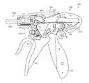
- FIG. 11illustrates the lock system of FIG. 9 in an actuated and unlocked configuration and the first drive system of FIG. 4 in an actuated configuration.
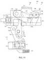
- FIG. 12illustrates the lock system of FIG. 9 in an unactuated and locked configuration and the first drive system of FIG. 4 in an actuated configuration.
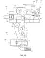
- FIG. 13illustrates the lock system of FIG. 9 in an actuated and unlocked configuration and the first drive system of FIG. 4 in an actuated configuration.
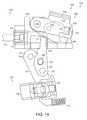
- FIG. 14illustrates the lock system of FIG. 9 returned to a locked configuration.
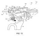
- FIG. 15illustrates the toggle clamp of the first drive system in a completely actuated configuration and the trigger of FIG. 4 operably engaged with a second drive system.
- FIG. 16illustrates a trigger gear portion of the trigger of FIG. 4 operably engaged with a compound gear system of the second drive system.
- FIG. 17illustrates the end effector of FIG. 3 in a fully closed position and the knife bar of FIG. 3 in a partially advanced position.
- FIG. 18illustrates the trigger of FIG. 4 in a fully actuated position and a rack of the second drive system of FIG. 15 in a fully advanced position.
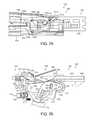
- FIG. 19illustrates the end effector of FIG. 3 in a fully closed position and the knife bar of FIG. 3 in a fully advanced position proximal to a distal end of the end effector.
- FIG. 20is a detail view of the distal end of the end effector of FIG. 19 .
- FIG. 21illustrates a return plate of the handle of FIG. 2 operably engaged with the trigger gear of FIG. 16 .
- FIG. 21also illustrates the trigger of FIG. 4 and the rack of FIG. 18 in a partially retracted, or partially returned, position.
- FIG. 22illustrates the trigger of FIG. 4 and the rack of FIG. 18 in a further partially retracted, or further partially returned, position.
- FIG. 23illustrates the trigger of FIG. 4 engaged with the toggle clamp of FIG. 6 and the toggle clamp being moved from its fully actuated configuration to a partially actuated configuration.
- FIG. 23also illustrates the rack of FIG. 18 in a further partially retracted, or further partially returned, position and the lock system of FIG. 9 re-engaged with the rack of FIG. 18 .
- FIG. 24illustrates the toggle clamp of FIG. 6 in a further partially actuated configuration and the rack of FIG. 18 in a further partially retracted, or further partially returned, position.
- FIG. 25illustrates the end effector of FIG. 3 in a partially opened position and the knife bar of FIG. 3 in a partially retracted position.
- FIG. 26illustrates the toggle clamp of FIG. 6 in an unactuated configuration.
- FIG. 27illustrates the end effector of FIG. 3 in a fully opened position and the knife bar of FIG. 3 in a fully retracted position.
- FIG. 28illustrates the toggle clamp of FIG. 6 in an unactuated configuration and the rack of FIG. 18 in a fully retracted position.
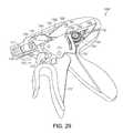
- FIG. 29is a perspective view of a handle of an alternative embodiment of a surgical instrument in an unactuated configuration illustrated with various components removed.
- FIG. 30is another perspective view of the handle of FIG. 29 in a partially actuated position illustrating a trigger coming into operative engagement with a gear of a second drive system.
- FIG. 31is a perspective view of the lock system of FIG. 9 in an unactuated, but locked configuration with an alternative embodiment of a rack of the second drive system.
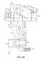
- FIG. 32is an elevational view of the lock system of FIG. 9 in the unactuated, but locked configuration of FIG. 31 .
- FIG. 32further illustrates a button switch of the lock system in an unactuated configuration.
- FIG. 33illustrates the button switch of FIG. 32 in an actuated position.
- FIG. 34illustrates the button switch of FIG. 32 in an actuated position, a link of the lock system in an actuated position, and the lock of the lock system in an unlocked position.
- FIG. 34Ais a detail view of the lock of FIG. 34 and a lock spring configured to bias the lock into engagement with the rack.
- FIG. 35illustrates the lock system of FIG. 9 in an actuated, unlocked configuration and the rack of FIG. 31 in an unadvanced position.
- FIG. 36illustrates the lock system of FIG. 9 in an actuated, unlocked configuration and the rack of FIG. 18 in an unadvanced position.
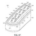
- FIG. 37illustrates a jaw of an end effector in accordance with at least one embodiment.
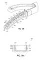
- FIG. 38illustrates a jaw of an end effector comprising steam control paths in accordance with at least one embodiment.
- FIG. 38Ais a cross-sectional view of the jaw of FIG. 38 illustrating the steam control paths extending through an electrode of the end effector. Various components of the end effector have been removed in FIG. 38A .
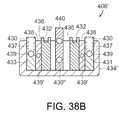
- FIG. 38Bis a cross-sectional view of a jaw of an alternative embodiment of an end effector illustrating steam control paths in supply electrodes, return electrodes, insulators positioned intermediate the supply electrodes and the return electrodes, and a cutting member movable within the end effector.
- FIG. 39illustrates a jaw of an end effector comprising a movable electrode.
- FIG. 40illustrates a jaw of an end effector comprising first and second insulators which are movable relative to an electrode.
- FIG. 41illustrates a trigger assembly of an alternative embodiment of a surgical instrument, wherein the trigger assembly further comprises a mechanism for limiting the force that can be transmitted through the trigger assembly.
- FIG. 41further illustrates a first part of the trigger assembly (illustrated with phantom lines) moved relative to a second part of the trigger assembly.
- FIG. 42is an elevational view of the first part of the trigger assembly.
- FIG. 43is an elevational view of the second part of the trigger assembly.
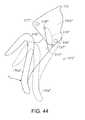
- FIG. 44illustrates a trigger assembly of an alternative embodiment of a surgical instrument, wherein the trigger assembly further comprises a mechanism for limiting the force that can be transmitted through the trigger assembly.
- FIG. 44further illustrates a first part of the trigger assembly (illustrated with phantom lines) moved relative to a second part of the trigger assembly.
- FIG. 45is a diagram of an energy trigger assembly in accordance with at least one alternative embodiment of the present invention.
- FIG. 46is a diagram of another energy trigger assembly in accordance with at least one alternative embodiment of the present invention.
- proximal and distalmay be used throughout the specification with reference to a clinician manipulating one end of an instrument used to treat a patient.
- proximalrefers to the portion of the instrument closest to the clinician and the term “distal” refers to the portion located furthest from the clinician.
- distalrefers to the portion located furthest from the clinician.
- spatial termssuch as “vertical,” “horizontal,” “up,” and “down” may be used herein with respect to the illustrated embodiments.
- surgical instrumentsmay be used in many orientations and positions, and these terms are not intended to be limiting and absolute.
- a surgical instrumentcan be configured to supply energy, such as electrical energy and/or heat energy, for example, to the tissue of a patient.
- a surgical instrumentsuch as surgical instrument 100
- the handle 102can comprise one or more switches or triggers which can be configured to supply electrical energy to end effector 106 and/or advance a knife or cutting member within the end effector 106 , for example, in order to transect the tissue positioned within the end effector 106 .
- the handle 102can comprise one or more electrical inputs, such as input, or terminal, 110 , for example, which can be operably coupled with a power supply, such as a voltage supply, for example.
- a power supplysuch as a voltage supply, for example.
- a power supplycan provide an electrical current to the surgical instrument 100 , wherein the magnitude, duration, wave form, and/or frequency, for example, of the current can be sufficiently controlled or modulated to provide a desired amount of energy to the surgical instrument 100 .
- Such power suppliesare well known within the art and a more detailed description thereof is not required.
- the handle 102can comprise a handle body 112 which, as described in greater detail below, can be configured to operably support a switch or trigger, such as trigger system 120 , for example, which can be configured to electrically couple electrical input 110 with a conductor in shaft 104 such that the current supplied to input 110 can be transmitted to end effector 106 .
- handle body 112can comprise two portions which are assembled together to form handle body 112 . As the reader will note, only one of the portions, or halves, is depicted in FIG. 1 , although the other portion, or half, can be a mirror image of, or at least substantially similar to, the half depicted in FIG. 1 .
- the halves of handle body 112can be snap-fit, press-fit, adhered, and/or fastened to one another.
- the electrical conductor within the shaft 104can comprise a wire, such as insulated wire, for example, which can extend between trigger system 120 and an electrode 130 ( FIG. 3 ) in end effector 106 .
- the handle 102can further comprise a supply wire 114 which can be electrically coupled with an electrical supply conductor (not illustrated) encased within an outer housing, or spine, 105 ( FIG. 8 ) of the shaft 104 .
- the supply conductorcan comprise a conductive insert, comprised of copper, for example, which is at least partially positioned within an insulative plastic jacket or sheath, for example, of the spine 105 .
- the plastic jacketcan be molded over the conductive insert during an injection molding process.
- the handle 102can comprise a slip ring 116 which can be configured to electrically couple wire 114 with the supply conductor within shaft 104 .
- the slip ring 116can comprise a circular, or an at least semi-circular, contact, for example, mounted to handle body 102 which can remain in contact with a corresponding circular, or an at least semi-circular, contact mounted to shaft 104 .
- Such corresponding contactscan permit relative rotational movement between shaft 104 and handle 102 and yet still provide an electrical path between wire 114 and the electrical supply conductor within shaft 104 .
- the shaft 104can further comprise another slip ring connector which, similar to the above, can maintain electrical contact between the supply conductor of shaft 104 and a supply contact 132 ( FIG. 3 ) of electrode 130 .
- electrical currentcan flow from the electrical input 110 , through supply wire 114 , through the electrical conductor in shaft 104 , and into the electrode 130 such that current can flow from the electrode 130 and into the tissue captured within the end effector 106 .
- the end effectorcan further comprise one or more return electrodes and/or conductors which can comprise a return path, or circuit, for the current.
- the return pathcan comprise a slip ring contact operably coupled with a return electrode in the end effector 106 and a return conductor embedded within the shaft 104 , for example.
- the handle 102can further comprise a slip ring 117 , for example, which can maintain the return conductor within shaft 104 in electrical contact with return wire 115 .
- the return wire 115can extend between the slip ring 117 and an electrical output, or terminal, which can, in various embodiments, be positioned adjacent to electrical input, or terminal, 110 .
- an end effector 306can comprise an electrode 330 which can extend between a proximal end of end effector 306 and a distal end 307 of end effector 306 .
- the electrode 330can comprise a first lateral portion 331 extending along a first side of jaw member 334 , a second lateral portion 333 extending along a second side of jaw member 334 , and a transverse intermediate portion 335 connecting the first lateral portion 331 and the second lateral portion 333 .
- the first jaw membercan further comprise a return electrode and/or the end effector can further comprise a second jaw member having a return electrode which can be positioned opposite the first jaw member.
- the trigger system 120can comprise a button 122 which can be selectively actuated in order to electrically couple the electrical input 110 with supply wire 114 and/or selectively actuated in order to electrically couple the return wire 115 with the electrical output of handle 102 .
- the button 122can be movable between an undepressed, or unactuated, position in which current cannot flow to electrode 130 , and a depressed, or actuated, position in which current can flow to electrode 130 .
- button 122can be used to actuate the switch 123 , and/or any other suitable switch
- other energy actuation mechanismssuch as toggles, levers, and/or any suitable actuators, can be used in addition to or in lieu of the above.
- the electrical currentcan pass through the tissue positioned against and/or surrounding the electrode 330 , for example.
- the current flowing through the electrode 330can generate heat within the electrode and the surrounding tissue.
- the heatcan denature the collagen within the tissue and, in co-operation with clamping pressure provided by the jaws of the end effector, the denatured collagen can form a seal within the tissue, for example.
- the first side 331 of electrode 330can be configured to create a first seal within the tissue and the second side 333 of electrode 330 can be configured to create a second seal within the tissue.
- one or more of the jaw members of an end effectorcan comprise grasping portions which can be utilized to manipulate tissue within a surgical site and/or position and hold the tissue within the end effector.
- first jaw member 334can comprise at least one grasping member, such as a grasping portion 337 , for example, which can be comprised of an electrically non-conductive, or insulative, material, such as plastic and/or ceramic, for example.
- the grasping portions 337can hold the tissue within the end effector without conducting, or at least not significantly conducting, current and/or heat to the tissue.
- the possibility of the treated tissue adhering to, or becoming stuck to, the grasping portions 337can be reduced or eliminated.
- each grasping portion 337can comprise an array or row of teeth 339 , for example, wherein, in at least one embodiment, a first grasping portion can comprise a first array or row of teeth 339 and a second grasping portion can comprise a second array or row of teeth 339 .
- the first row of teeth 339can be positioned adjacent to the first lateral portion 331 of electrode 330 and the second row of teeth 339 can be positioned adjacent to the second lateral portion 333 of electrode 330 .
- the grasping portions 337can be comprised of an electrically non-conductive plastic, glass, and/or ceramic, for example, and, in at least one embodiment, the grasping portions 337 can be formed by an injection molding process.
- at least one lubricant additivesuch as TEFLON, for example, can be mixed or embedded within the plastic.
- the one or more lubricantscan prevent, or at least inhibit, the tissue captured within the end effector 306 from sticking or adhering to the teeth 339 , for example.
- at least one lubricantsuch as Teflon, for example, can be coated on the grasping portions 337 .
- the grasping portions 337can be comprised of an electrically conductive material which can be coated, or at least partially coated, with an electrically non-conductive material, for example.
- At least one of the jaws, such as first jaw 434 , for example, of end effector 406can comprise at least one steam control path, passage, or conduit for conveying the steam, and/or other vapors created by the current and/or heat, away from the surgical site.
- an electrodesuch as electrode 430
- the steam control pathcan comprise one or more passages 439 which can extend longitudinally through the first lateral portion 431 and the second lateral portion 433 of electrode 430 , for example.
- the steam control pathscan further comprise one or more passages, or holes, 437 which can extend between an outside surface of electrode 430 and the passages 439 such that steam can flow from the tissue being treated, through the holes 437 , and into the passages 439 .
- the passage 439 extending though the first lateral portion 431 and the passage 439 extending through the second lateral portion 433can be in fluid communication via a passage within intermediate portion 435 of electrode 430 .
- the shaft of the surgical instrumentsuch as shaft 104 of surgical instrument 100 , for example, can comprise one or more passages or conduits therein which can be in fluid communication with the passages 439 , for example, such that the heated vapors can be conveyed away from the end effector and out of the patient.
- the handle of the surgical instrumentsuch as handle 102 , for example, can comprise at least one vent configured to allow the heated vapors to vent into the atmosphere surrounding the patient, for example.
- a jaw 434 ′ of an end effector 406 ′can comprise, similar to the above, a supply electrode 430 having first and second portions 431 , 433 and steam control paths comprising passages 437 , 439 extending therethrough.
- the end effector 406 ′can further comprise at least one return electrode 436 and one or more electrically non-conductive insulators 438 positioned intermediate portions of the supply electrode 430 and portions of the return electrode 436 .
- the return electrode and/or the insulatorscan comprise one or more steam control paths for conveying steam away from the tissue being treated.
- the return electrodecan comprise one or more channels 432 therein which can be configured to convey the steam in a space intermediate the tissue and an outside surface of the return electrode 436 .
- the insulators 438can comprise one or more passages 439 ′ extending therethrough. Although passages 437 , 439 , and 439 ′ are illustrated as comprising round, or at least substantially round, elongate configurations, the passages extending through the supply electrode, the return electrode, and/or the insulators can comprise any suitable configuration, such as square and/or rectangular configurations, for example.
- channels 432are illustrated as having substantially orthogonal sidewalls, the sidewalls of the channels can comprise any suitable configuration, such as arcuate and/or semi-circular configurations, for example.
- any one of the supply electrode, return electrode, and/or insulatorscan comprise any suitable number of exterior channels and/or internal passages therein for conveying heated vapors away from the tissue in the end effector.
- a cutting member 440can comprise one or more steam paths 439 ′′ extending therethrough.
- surgical instrument 100can comprise a trigger system, such as trigger system 120 , for example, which can be configured to prevent the cutting member 140 ( FIG.
- the cutting member 140can be advanced at the same time that current is supplied to electrode 130 . In certain other embodiments, the current can be supplied to electrode 130 prior to cutting member 140 being advanced to transect the tissue.
- the trigger system 120can comprise an energy actuation button 122 mounted to a first link 124 , a second link 126 operably coupled with first link 124 , and a pivotable lock 150 which can be moved between a locked position and an unlocked position by second link 126 .
- the button 122can be moveable between an unactuated, or undepressed, position ( FIG. 32 ) and an actuated, or depressed, position ( FIG. 33 ) in order to electrically connect, or couple, a first portion 114 a of supply wire 114 and a second portion 114 b of supply wire 114 .
- the trigger system 120can further comprise a switch 123 mounted to first link 124 which can be switched, or closed, when button 122 is depressed such that current can flow from the electrical input 110 , through the first supply wire portion 114 a , and into the second supply wire portion 114 b and slip ring 116 . As described above, the current can then flow to electrode 130 , through return wire 117 , and then through the electrical outlet in order to complete the electrical circuit.
- the switch 123can comprise a spring, such as a linear coil spring, for example, positioned therein which can be compressed when the button 122 is moved from its unactuated position to its actuated position.
- the coil springcan be positioned intermediate the button 122 and a housing of the switch 123 and/or first link 124 .
- a forceis required to compress the spring and, in addition, the button 122 is required to move a predetermined distance in order to actuate switch 123 .
- the force applied to button 122 in order to actuate switch 123can cause first link 124 to move. More particularly, the force applied to button 122 can be transmitted through the coil spring to switch 123 wherein the force can then be transferred to first link 124 .
- the first link 124can comprise a first end 125 pivotably mounted to handle body 112 via a pivot or pin 118 extending from handle body 112 and through an aperture in first end 125 . When first link 124 is moved by the force, the first link 124 can rotate or pivot about an axis defined by pin 118 in a direction indicated by arrow A ( FIG. 32 ).
- the first link 124can further comprise a drive member 127 extending therefrom which can be configured to move second link 126 .
- the second link 126can comprise a first end 129 pivotably mounted to handle body 112 via a pivot or pin 119 extending from handle body 112 and through an aperture in first end 129 .
- the drive member 127can extend into a slot 128 in second link 126 such that, when the first link 124 is rotated about pivot 118 in direction A, the second link 126 can be rotated about pivot 119 in a direction indicated by arrow B ( FIG. 32 ).
- the drive member 127 extending into slot 128can engage a sidewall of the slot 128 so as to transmit movement between first link 124 and second link 126 .
- the second link 126can further comprise a second end 151 which can be configured to engage rack 150 and rotate rack lock 150 between an unactuated, locked position ( FIG. 33 ) and an actuated, unlocked position ( FIG. 34 ). More particularly, when second link 126 is rotated in direction B, the rack lock 150 can be rotated in a direction indicated by arrow C ( FIG. 32 ) about an axis defined by pivot 152 on yoke 154 . When rack lock 150 is sufficiently rotated in direction C, as described in greater detail further below, tooth 155 extending from rack lock 150 may be sufficiently removed from notch 162 a in rack 160 such that rack 160 can be moved relative to lock 150 .
- the force applied to button 122 in order to actuate switch 123can rotate first link 124 about pivot 118 , rotate second link 126 about pivot 119 , and rotate rack lock 150 between locked and unlocked positions.
- a forcecan be sufficient to actuate switch 123 and unlock rack 150 at the same time, or at least substantially the same time.
- energycan be supplied to the electrode 130 at the same time that rack 160 becomes unlocked and capable of advancing knife bar 140 distally within end effector 106 as described in greater detail below.
- the trigger system 120can assure that the tissue positioned within the end effector is not transected before it is at least partially treated and/or sealed.
- the trigger system 120can further comprise a trigger spring 121 operably engaged with the first link 124 , for example, which can be configured to resist the movement of first link 124 in the direction indicated by arrow A.
- the force applied to button 122 to actuate switch 123may be insufficient to rotate first link 124 and second link 126 a sufficient distance to move rack lock 150 into its unlocked position.
- the switch 123can be actuated to supply electrode 130 with current while the rack 160 can remain locked in place by rack lock 150 .
- the tooth 155 of rack lock 150can remain biased into first notch 162 a by lock spring 156 such that rack 160 is prevented from moving, or at least substantially moving, relative to rack lock 150 .
- a rack lockmay be slid between a first position in which it is locked with a rack, such as rack 160 , for example, and a second position in which it is unlocked from the rack.
- the rack lockcan be moved along a straight line.
- a larger, or second, forcemay need to be applied to button 122 and/or first link 124 . More particularly, in the event that the force, or first force, used to depress button 122 and actuate switch 123 is insufficient to unlock rack lock 150 , a second, or larger, force can be applied to button 122 , for example, in order to sufficiently compress spring 121 , sufficiently rotate first link 124 and second link 126 , and rotate rack lock 150 into an unlocked position. In such circumstances, a clinician may apply a light force to button 122 in order to actuate the electrical energy system and a heavier force to button 122 in order to unlock the rack 160 .
- trigger spring 121can be positioned intermediate first link 124 and handle body 112 such that trigger spring 121 is compressed as first link 124 is rotated in the direction indicated by arrow A.
- the length and/or stiffness of trigger spring 121can be selected such that the coil spring within switch 123 is sufficiently compressed to supply electrode 130 with electrical energy before the trigger spring 121 is sufficiently compressed to unlock rack 160 .
- the treatment or sealing of the tissue positioned within the end effector 106for example, can begin before rack 160 and cutting member 140 can be advanced.
- the difference between the first force and the second forcecan be large enough such that a surgeon, or other clinician, using the surgical instrument 100 may be provided with a tactile feedback as to whether the surgical instrument is in a first operating condition in which energy is being applied to the tissue and the cutting member is not being advanced within the end effector and a second operating condition in which energy is being applied to the tissue and the cutting member is being advanced within the end effector to transect the tissue.
- the switch spring and the trigger spring 121can be selected such that a significantly smaller force is required to depress button 122 and actuate switch 123 as compared to a significantly larger force required to unlock rack lock 150 .
- the stiffness of the spring in switch 123 and the stiffness of trigger spring 121can be selected such that a force which is sufficient to actuate button 122 can also be sufficient to rotate lock 150 into an unlocked configuration.
- the force necessary to actuate button 122can be the same, or at least substantially the same, as the force necessary to unlock rack 160 .
- the surgeoncan release button 122 such that the spring of switch 123 can return button 122 to an unactuated position and operably disconnect first portion 114 a and second portion 114 b of supply wire 114 .
- electrical currentmay no longer flow to electrode 130 and, as a result, the electrode 130 and the tissue within the end effector may begin to cool.
- the trigger spring 121may return first link 124 and/or second link 126 to their unactuated positions and the lock spring 156 may return rack lock 150 to an unlocked position. More particularly, referring now to FIG.
- the lock spring 156can reposition the lock tooth 155 within the notch 162 a and relock the rack 160 in position.
- the rack 160may be sufficiently advanced such that the rack tooth 155 cannot be reseated within the notch 162 a and, as a result, the lock spring 156 may position the tooth 155 against a top surface 161 of rack 160 in an unlocked position. In such circumstances, the rack 160 and the cutting member 140 can be advanced within the tissue without current flowing to the electrode 130 .
- a rack 160 ′can comprise a plurality of notches 162 a - 162 e , for example, which can, once the button 122 has been released, allow the lock spring 156 to return the lock 150 to a locked configuration even though the rack 160 ′ and the cutting member 140 have already been advanced. More particularly, depending on the distance that rack 160 has been advanced, the lock spring 156 can position the lock tooth 155 in any one of the notches 162 b - 162 e , for example.
- the surgeonmay keep the button 122 depressed and the first link 124 and the second link 126 sufficiently rotated in order to keep the lock 150 in an unlocked position.
- electrical energycan be supplied to the electrode 130 during the entire, or at least substantially entire, advancement of rack 160 and cutting member 140 .
- lock spring 156can be configured to bias lock 150 into engagement with rack 160 .
- lock spring 156can comprise a torsion spring including a coil 156 a positioned about pivot pin 152 , a first end extending from coil 156 a mounted to yoke 154 , and a second end 156 b .
- the second end 156 bcan comprise a torque arm which, when the lock 150 is rotated about pivot pin 152 as described above, the second end 156 b can torque or compress the spring coil 156 a .
- the spring 156can store potential energy therein which, when released, can act to move lock 150 from its unlocked position into its locked position.
- the second end 156 bcan comprise a hook or attachment portion 156 c which can mount the second end 156 b to lock 150 such that the second end 156 b moves the lock 150 .
- the distance to move button 122 from an unactuated position to an actuated positioncan be shorter than the distance to rotate link 124 sufficiently to move lock 150 between a locked position and an unlocked position.
- the actuation of button 122although it may cause first link 124 and second link 126 to rotate, may be insufficient to rotate first link 124 and second link 126 a sufficient distance to move lock 150 into its unlocked configuration.
- the button 122can be depressed to supply electrical energy to the electrode 130 while the rack 160 , for example, can remain locked in position by rack lock 150 .
- the tissuecan be sealed, or at least partially sealed, before the cutting member 140 is advanced through the tissue within the end effector 106 .
- the button 122 and the first link 124can be moved an additional distance in order to sufficiently rotate lock 150 into an unlocked configuration such that rack 160 and cutting member 140 can be advanced into and/or through the tissue.
- the button 122can be moved a first distance to supply electrical current to electrode 130 although the button 122 can be moved a total distance which is greater than the first distance to unlock rack lock 150 .
- the difference between the first distance and the total distance that button 122 is movedcan be sufficient to provide a sufficiently large window of operation to allow the surgeon to move button 122 within a range of distances while not unlocking the rack lock 150 .
- the distance necessary to actuate button 122may the same, or at least substantially the same, as the distance necessary to move lock 150 between its locked and unlocked configurations.
- rack 160 and cutting member 140can be advanced toward distal end 107 ( FIG. 3 ) of end effector 106 .
- the advancement of cutting member 140can, one, move jaw 108 toward jaw 109 and, two, incise the tissue captured between jaw 108 and jaw 109 .
- the handle 102can further comprise a trigger 170 which can be moved between an unactuated position, as illustrated in FIG. 1 , and an actuated position, as illustrated in FIG. 18 .
- the movement of trigger 170 between its actuated position and unactuated positioncan define one stroke of trigger 170 , although such a stroke can comprise two different ranges of motion. More particularly, in at least one embodiment, the stroke can comprise a first range of motion which drives a first drive system and a second range of motion which drives a second drive system.
- the trigger 170in co-operation with the first drive system, can advance the rack 160 and the cutting member 140 between a first position ( FIG. 3 ) and a second position ( FIG. 7 ) during the first range of motion of trigger 170 , wherein the trigger 170 , in co-operation with the second drive system, can advance the rack 160 and the cutting member 140 between a second position ( FIG.
- the cutting member 140can move the second jaw 108 toward the first jaw 109 and clamp tissue positioned therebetween.
- the cutting member 140can be advanced toward the distal end 107 to incise the tissue clamped between jaw 108 and jaw 109 .
- the first drive systemcan comprise a toggle clamp 180 which can be moved between a first configuration ( FIG. 2 ) associated with the first position ( FIG. 3 ) of cutting member 140 and a second configuration ( FIG. 6 ) associated with the second position ( FIG. 7 ) of cutting member 140 .
- the toggle clamp 180referring again to FIG. 2 , can comprise a first link 182 and a second link 184 .
- the first link 182can comprise a first end pivotably mounted to handle body 112 at first pivot 181 , via a pivot pin, for example, and, in addition, the second link 184 can comprise a first end pivotably mounted to yoke 154 at a second pivot 183 , also via a pivot pin, for example. Further to the above, the first link 182 and the second link 184 can each comprise second ends which are pivotably mounted to each other via an intermediate pivot pin 185 , for example.
- the intermediate pivot pin 185can comprise a vertex of an angle defined between a first line, or axis, 186 extending through the centers of first pivot 181 and intermediate pivot 185 and a second line, or axis, 187 extending through the centers of second pivot 183 and intermediate pivot 185 .
- the first line 186 and the second line 187can define a vertex angle ⁇ therebetween.
- Opposite vertex angle ⁇is a line, or axis, 188 defined between the center of first pivot 181 and the center of second pivot 183 .
- the vertex angle ⁇can be about 90 degrees and/or slightly greater than 90 degrees, for example. In at least one embodiment, angle ⁇ can be about 120 degrees when toggle clamp 180 is in its first configuration, for example. Although such angles may be suitable in various circumstances, any other suitable angle can be used.
- the trigger 170can be moved from its unactuated position ( FIG. 2 ) into a partially actuated position ( FIG. 4 ) as part of its first range of motion.
- trigger 170is pivotably mounted to handle body 112 via a pivot 171 , such as a pivot pin, for example.
- trigger 170can begin to move the toggle clamp 180 from its first configuration ( FIG. 2 ) into its second configuration ( FIG. 6 ).
- the trigger 170can further comprise a cam, or driver, 172 extending therefrom which can be configured to engage first link 182 and lift the second end of link 182 upwardly and, at the same time, rotate first link 182 about first pivot 181 in a direction indicated by arrow D ( FIG. 4 ).
- a cam, or driver, 172extending therefrom which can be configured to engage first link 182 and lift the second end of link 182 upwardly and, at the same time, rotate first link 182 about first pivot 181 in a direction indicated by arrow D ( FIG. 4 ).
- the upward movement of the second end of first link 182can cause the second end of second link 184 to move upwardly and, at the same time, rotate about second pivot 183 in a direction indicated by arrow E ( FIG. 4 ).
- the first link 182can comprise a cam, or drive, pocket 173 which can be engaged by cam, or driver, 172 in order to transmit the rotation of trigger 170 to first link 182 .
- the yoke 154can translate distally in a direction indicated by arrow F ( FIG. 4 ).
- the distal movement of yoke 154 in the direction Fcan be transmitted to rack 160 and cutting member 140 such that rack 160 and cutting member 140 are also moved in direction F.
- the rack lock 150 mounted to yoke 154when engaged with rack 160 , can allow the yoke 154 to pull the rack 160 distally when the yoke 154 is pushed distally by toggle clamp 180 as described above.
- the distal movement of rack 160can be transmitted to cutting member 140 .
- the cutting member 140can comprise a proximal portion 142 which can be connected to the distal end 165 of rack 160 .
- a connectioncan prevent, or at least inhibit, relative longitudinal movement between cutting member proximal end 142 and rack distal end 165 while permitting relative rotational movement therebetween owing to a round head 143 of the proximal end 142 captured within a round cavity in the distal end 165 of rack 160 .
- the proximal movement of cutting member 140can, in at least one embodiment, cause cutting member 140 to engage the second jaw 108 and move, or rotate, second jaw 108 toward first jaw 109 .
- the cutting member 140can comprise one or more cams, or cam pins, 144 a which can be configured to engage one or more cam surfaces 145 on second jaw 108 and rotate second jaw 108 downwardly about one or more pivot pins 103 , for example.
- the rotation of trigger 170 through its first range of motioncan move the toggle clamp 180 between its first, or unactuated, configuration ( FIG. 2 ) and its second, or fully actuated, configuration ( FIG. 6 ).
- the movement of the toggle clamp 180 between its first configuration and its second configurationcan move the cutting member 140 between its first position ( FIG. 3 ) and its second position ( FIG. 7 ) and, as a result, move second jaw 108 between its fully open position ( FIG. 3 ) and its fully closed position ( FIG. 7 ).
- the vertex angle ⁇ defined between first line 186 and second line 187is about 180 degrees, for example.
- the vertex angle ⁇can be about 175 degrees, for example.
- the toggle clamp 180can transmit a very large longitudinal force to rack 160 and cutting member 140 in the distal direction F.
- this very large longitudinal forcecan increase exponentially and/or asymptotically as the vertex angle ⁇ approaches approximately 180 degrees.
- This very large longitudinal forcecan apply a large biasing force to second jaw 108 such that a large clamping force, or pressure, is applied to the tissue positioned intermediate the first jaw 109 and the second jaw 108 .
- the distal movement of yoke 154can compress a yoke spring, such as axial spring 147 , for example, intermediate yoke 154 and a spine 105 of shaft 104 .
- a yoke springsuch as axial spring 147
- the axial spring 147can store potential energy therein which can be released in order to at least partially retract rack 160 and cutting member 140 .
- the toggle clamp 180is illustrated in its first, or unactuated configuration, in FIG. 8 , the axial spring 147 is at least partially compressed between shaft spine 105 and yoke 154 .
- the compression force applied to shaft spine 105 and yoke 154 by spring 147can provide an additional benefit of inhibiting relative movement between shaft spine 105 and yoke 154 .
- FIG. 9which illustrates the toggle clamp 180 in its first configuration and the trigger assembly 120 in its unactuated configuration
- the rack lock 150is in its locked position and rack 160 is in its unadvanced position.
- the trigger assembly 120can be actuated so as to rotate first link 124 about pivot 118 and rotate second link 126 about pivot 119 ; however, in circumstances where the rack 160 and cutting member have not yet been advanced into their second positions, for example, the actuation of trigger assembly 120 may not move rack lock 150 into its unlocked position.
- rack 160 and cutting member 140Upon the advancement of rack 160 and cutting member 140 into their second positions, referring now to FIG.
- the rack lock 150can be moved into contact with second link 126 such that rack lock 150 is rotated from its locked position to its unlocked position.
- the rack 160 and cutting member 140can be advanced from their first positions ( FIG. 9 ) to their second positions ( FIG. 12 ) when the toggle clamp 180 is moved from its first configuration into its second configuration, as described above, and wherein, upon a sufficient actuation of trigger assembly 120 , as described above, the second link 126 can contact rack lock 150 and rotate rack lock 150 into its unlocked configuration as illustrated in FIG. 13 .
- trigger 170upon the completion of its first range of motion, become operably disengaged from the first drive system and/or operably engaged with the second drive system.
- FIG. 15depicts the trigger 170 at the end of its first range of motion
- the cam 172is no longer positioned within pocket 173 in first link 182 .
- the cam 172may no longer drive the toggle clamp 180 despite any further rotation of trigger 170 toward its actuated position ( FIG. 18 ), and, as a result, the trigger 170 may be operably disconnected from the first drive system.
- the trigger 170has been moved into operative engagement with trigger gear 175 and the second drive system. More particularly, referring now to FIG.
- the trigger 170can further comprise a drive pin 176 extending therefrom which is configured to contact the bottom surface 177 of trigger gear 175 and, once engaged with trigger gear 175 , push, or rotate, the trigger gear 175 upwardly such that the trigger gear 175 rotates a compounding gear 191 of the rack and pinion system 190 as trigger 170 is moved through its second range of motion.
- the trigger gear 175comprises an array of teeth 178 which are operably engaged with, or meshed with, the compounding gear 191 while the trigger 170 is moved through its first range of motion, although, the teeth 178 do not drive the compounding gear 191 during the first range of motion of trigger 170 .
- the rotation of trigger 170 in its second range of motioncan cause trigger gear 175 to drive or rotate compounding gear 191 as described in greater detail further below.
- the disengagement of cam 172 from pocket 173 in first link 182can occur at the same time, or at least substantially the same time, as the trigger 170 comes into operative engagement with trigger gear 175 .
- the trigger 170may not come into operative engagement with trigger gear 175 until after the cam 172 has been disengaged from pocket 173 .
- the rotation of trigger 170may comprise a dwell period in which the trigger 170 is not operatively engaged with either the first drive system of the second drive system.
- the further rotation of trigger 170can, one, cause the cam 172 to move relative to a bottom surface 187 of first link 182 , and, two, rotate compounding gear 191 .
- the compounding gear 191can be mounted to a pin 192 which can be rotatably mounted between the two halves of handle body 112 .
- the rack and pinion system 190can further comprise an additional, or second, compounding gear 193 which can be mounted to pin 192 .
- the compounding gears 191 , 193can be mounted to pin 192 such that the rotation of one of compounding gears 191 , 193 causes the rotation of the other of the compounding gears 191 , 193 .
- the rack and pinion system 190can further comprise a third compounding gear 195 which can be mounted to a pin 194 which can be rotatably mounted between the two halves of handle body 112 .
- the third compounding gear 195can be operably meshed with the second compounding gear 193 such that the rotation of second compounding gear 193 can rotate the third compounding gear 195 .
- the rack and pinion system 190can further comprise a pinion gear 197 which can also be mounted to pin 194 , wherein, similar to the above, the compounding gear 195 and the pinion gear 197 can be mounted to pin 194 such that the rotation of one of gears 195 , 197 causes the rotation of the other of the gears 195 , 197 .
- the pinion gear 197is operably or meshingly engaged with the rack teeth 164 on rack 160 such that the rotation of pinion gear 197 can move, or displace, rack 160 along a straight, or at least substantially straight, path, for example.
- the rotation of trigger 170can be transmitted to pinion gear 197 via compounding gears 191 , 193 , and 195 such that, owing to the gear ratio of gears 191 , 193 , 195 , and 197 , a small rotation of trigger 170 can result in a large displacement of rack 160 and cutting member 140 .
- the rotation of trigger 170 through its second range of motioncan move cutting member 140 between its second position ( FIG. 17 ) and its third position ( FIG. 19 ). In its second position, referring to FIG.
- the cutting member 140can be positioned within the end effector 106 such that the knife edge 146 of cutting member 140 is positioned to be advanced through the tissue captured between first jaw 109 and second jaw 108 , and owing to the rotation of trigger 170 , trigger gear 175 , and gears 191 , 193 , 195 , and 197 , the rack 160 can be displaced in the distal direction F so as to displace the cutting member 140 toward the distal end 107 of end effector 106 .
- the cutting member 140In its third position, referring to FIGS. 18 and 19 , the cutting member 140 can be positioned at the distal end 107 of end effector 106 .
- FIG. 18 and 19the cutting member 140 can be positioned at the distal end 107 of end effector 106 .
- jaw 108 and/or jaw 109can comprise a slot 149 which can be configured to receive at least a portion of cutting member 140 and guide cutting member 140 toward the distal end 107 .
- the cam pins 144 a extending from cutting member 140can be configured to ride on top of cam surface 148 a on the outside of jaw 108 such that jaw 108 is compressed toward jaw 109 .
- cutting member 140can further comprise cam pins 144 b extending therefrom which can be configured to ride on cam surface 148 b on the outside of jaw 109 such that jaw 109 is compressed toward jaw 108 .
- jaw 108 and/or jaw 109can further comprise a stop 147 which can be configured to stop the distal displacement of cutting member 140 through the tissue.
- the stop 147can be positioned proximally with respect to the distal end of electrode 130 such that the knife edge 146 may not transect tissue which has not been sealed.
- a return springsuch as torsion spring 199 ( FIG. 28 ), for example, can reverse the rotation of compounding gears 191 , 193 , and 195 and pinion gear 197 in order to retract rack 160 and cutting member 140 in a proximal direction, i.e., in a direction opposite direction F.
- torsion spring 199FIG. 28
- one end of the torsion spring 199can be engaged with the compounding gear 191 and another end of the torsion spring 199 can be engaged with the handle body 112 , for example, such that potential energy stored within the torsion spring 199 when the rack 160 is advanced can be released when the trigger 170 is released in order to rotate compounding gear 191 in a reverse direction.
- the reverse rotation of compounding gear 191can, owing to the meshing engagement of trigger gear teeth 178 and compounding gear 191 , rotate trigger gear 175 downwardly in a direction indicated by arrow G.
- the downward rotation of trigger gear 175can be transmitted to trigger 170 via the interaction of drive surface 177 acting against the drive pin 176 in order to retract, or return, the trigger 170 through its second range of motion, as illustrated in FIG. 22 .
- the surgical instrumentcan further comprise a reversing plate 200 which can be operably engaged with compounding gear 191 such that the reverse rotation of compounding gear 191 can also be transmitted to trigger gear 175 via reversing plate 200 .
- the reversing plate 200can be keyed to compounding gear 191 and/or pin 192 such that, as compounding gear 191 is driven in a reverse direction by return spring 199 , the reversing plate 200 is driven downwardly and rotated about an axis defined by pin 192 in a direction indicated by arrow H. In such circumstances, referring to FIG. 22 , the reversing plate 200 can act against drive pin 202 extending from trigger gear 175 to drive trigger gear 175 downwardly.
- the return spring 199via gears 191 , 193 , 195 , and 197 , can return the cutting member 140 and the rack 160 from their third position to their second position and allow the rack lock 150 to re-engage the rack 160 as illustrated in FIG. 23 .
- the yoke spring 147can push yoke 154 , rack 160 , and cutting member 140 in a proximal direction, i.e., a direction opposite direction F.
- the yoke spring 147via yoke 154 , can move the rack 160 and the cutting member 140 from their second positions to their first positions.
- the cutting member 140can move second jaw 109 from its closed position to its open position. More particularly, in at least one embodiment, the cutting member 140 can further comprise at least one opening cam pin 141 extending therefrom which, when moved proximally, can engage cam surface 101 a on second jaw 109 such that second jaw 109 is pivoted upwardly about pivot pins 103 into its open position as illustrated in FIG. 27 . Once jaw 109 has been moved into its open position, the cam pin 141 can be further retracted such that it is positioned over and/or against lock surface 101 b which is positioned proximally with respect to cam surface 101 a .
- the second jaw 109can be locked or held in an open position by cam pin 141 .
- the drive pin 176 extending from trigger 170can engage the sidewall of a slot 204 in reversing plate 200 as trigger 170 is returned to its unactuated position. More particularly, the drive pin 176 can assure that the reversing plate 200 , the compounding gears 191 , 193 , 195 , and 197 , and the rack 160 have been returned to their initial positions and, as a result, assure that cutting member 140 has been returned to its initial position.
- the trigger 170comprises a drive pin 176 which, at the end of the first range of motion of trigger 170 , can contact the drive surface 177 of trigger gear 175 in order to move trigger gear 175 upwardly.
- the trigger 170 and trigger gear 175move together about a common axis of rotation defined by pivot 171 .
- the trigger 170 and trigger gear 175can, referring to FIGS. 21-24 , for example, move independently of one another and rotate relative to one another. More particularly, the trigger 170 and trigger gear 175 can move relative to one another about a pivot 179 on trigger 170 as trigger 170 is returned to its unactuated position and as the surgical instrument 100 is reset to its initial configuration.
- an alternative surgical instrumentcan comprise substantially the same components and systems as surgical instrument 100 , although the alternative surgical instrument can comprise a trigger assembly 170 ′ comprising a first portion 170 a ′ and a second portion 170 b ′. In certain embodiments, relative movement between the first portion 170 a ′ and the second portion 170 b ′ is possible during the actuation of trigger 170 ′.
- a force overload mechanismcan be positioned intermediate the first trigger portion 170 a ′ and the second trigger portion 170 b ′ such that, when the force applied to trigger portion 170 a ′ exceeds a predetermined value, the trigger portion 170 a ′ can move relative to the trigger portion 170 b ′ and prevent any force in excess of the predetermined value from being transmitted to trigger gear 175 via drive pin 176 ′.
- the first trigger portion 170 a ′can comprise a pivot hole 171 a ′ which can be aligned with, referring to FIG.
- first portion 170 a ′ and the second portion 170 b ′can rotate together about an axis defined by pivot 171 ′. More particularly, a force, or load, FA applied to first portion 170 a ′ can cause first portion 170 a ′ to rotate about pivot 171 ′ and, owing to drive pin 176 ′, the rotation of first portion 170 a ′ can be transmitted to second portion 170 b ′ in order to cause second portion 170 b ′ to be rotated about pivot 171 ′.
- a force, or load, FA applied to first portion 170 a ′can cause first portion 170 a ′ to rotate about pivot 171 ′ and, owing to drive pin 176 ′, the rotation of first portion 170 a ′ can be transmitted to second portion 170 b ′ in order to cause second portion 170 b ′ to be rotated about pivot 171 ′.
- the drive pin 176 ′can be slidably positioned within a slot 212 ′ within first portion 170 a ′, wherein the first portion 170 a ′ can further comprise a spring, such as an axial compression 216 ′, for example, configured to bias the drive pin 176 ′ against the end 214 ′ of slot 212 ′. As illustrated in FIG.
- the drive pin 176 ′can extend through a drive aperture 218 ′ in second portion 170 b ′, wherein, in various circumstances, at least a portion of the force FA applied to first trigger portion 170 a ′ can be transmitted through the spring 216 ′, drive pin 176 ′, and a sidewall of drive aperture 218 ′ in order to apply a force to second trigger portion 170 b′.
- the force transmitted between the first trigger portion 170 a ′ and the second trigger portion 170 b ′can be represented by a force FT ( FIG. 41 ) which is transmitted through spring 216 .
- the force FTcan be aligned, or collinear, with the longitudinal, or axial, axis of spring 216 ′.
- the force FTis at or below the predetermined, or threshold, value described above, the first portion 170 a ′ and the second portion 170 b ′ can move together with little, if any, relative movement therebetween.
- the spring 216 ′can be compressed between the drive pin 176 ′ and a second sidewall 215 ′ of the slot 212 such that the spring 216 ′ is compressed by a preload force which is equal to, or at least substantially equal to, the predetermined threshold value. In such circumstances, the spring 216 ′ may not be further compressed unless and if the force FT exceeds the predetermined threshold value. Once the force FT exceeds the predetermined threshold value, the spring 216 ′ may be further compressed, thereby permitting relative movement between first portion 170 a ′ and second portion 170 b ′.
- the force in excess of the predetermined threshold valuemay be absorbed by the spring 216 ′ instead of being transmitted to trigger gear 175 via drive pin 176 ′.
- Such embodimentscan prevent an excessive force from being applied to rack 160 and cutting member 140 and, as a result, an overload condition can be avoided, or at least partially ameliorated.
- an alternative surgical instrumentcan comprise substantially the same components and systems as surgical instrument 100 , although the alternative surgical instrument can comprise a trigger assembly 170 ′′′ comprising a first portion 170 a ′′′ and a second portion 170 b ′′′. In certain embodiments, relative movement between the first portion 170 a ′′′ and the second portion 170 b ′′′ is possible during the actuation of trigger 170 ′′′.
- a force overload mechanismcan be positioned intermediate the first trigger portion 170 a ′′′ and the second trigger portion 170 b ′′′ such that, when the force applied to trigger portion 170 a ′′′ exceeds a predetermined value, the trigger portion 170 a ′′′ can move relative to the trigger portion 170 b ′′′ and prevent any force in excess of the predetermined value from being transmitted to trigger gear 175 via drive pin 176 ′′′.
- first trigger portion 170 a ′′′ and the second trigger portion 170 b ′′′can be pivotable about pivot pin 171 ′′′, wherein a force, or load, FA applied to first portion 170 a ′′ can cause first portion 170 a ′′ to rotate about pivot 171 ′′′ and, owing to beam, or link, 216 ′′′, the rotation of first portion 170 a ′′′ can be transmitted to second portion 170 b ′′′ in order to cause second portion 170 b ′′′ to be rotated about pivot 171 ′′′.
- a first end 217 ′′ of beam 216 ′′′can be fixedly mounted to first trigger portion 170 a ′′′ and a second end 218 ′′′ of bean 216 ′′′ can be fixedly mounted to second trigger portion 170 b ′′′, wherein, in various circumstances, at least a portion of the force FA applied to first trigger portion 170 a ′′′ can be transmitted through the beam 216 ′′′ in order to apply a force to second trigger portion 170 b′′′.
- the first portion 170 a ′′ and the second portion 170 b ′′can move together with little, if any, relative movement therebetween.
- the beam 216 ′′can be configured such that, although the below-threshold force transmitted through beam 216 ′′ may create a compressive contraction or other minor elastic deformation within the beam 216 ′′, the beam 216 ′′ will remain largely undeflected as long as the force transmitted therethrough is below the threshold value.
- the beam 216 ′may buckle, thereby permitting relative movement between first portion 170 a ′ and second portion 170 b ′.
- Such relative movementis depicted in FIG. 44 which illustrates the first portion 170 a ′′ in phantom lines as having moved relative to second trigger portion 170 b ′′.
- the first end 217 ′′can move toward the second end 218 ′′ such that beam 216 buckles or collapses laterally.
- such bucklingcan be elastic or resilient which could allow the first trigger portion 170 a ′′ to be reset relative to the second trigger portion 170 b ′′.
- the bucklingcan be at least partially inelastic, or plastic, which may prevent or inhibit such a reset.
- the various embodiments described abovecan prevent an excessive force from being applied to rack 160 and cutting member 140 and, as a result, an overload condition can be avoided, or at least partially ameliorated.
- an alternative surgical instrument 100 ′′can comprise a one piece trigger 170 ′′ which can drive the first drive system and the second drive system described above. More particularly, in at least one embodiment, the trigger 170 ′′ can be, similar to the above, configured to be rotated between an actuated position and an unactuated position about pivot 171 during a stroke of trigger 170 ′′. Also similar to the above, this stroke of trigger 170 ′′ can comprise a first range of motion for driving the first drive system and a second range of motion for driving the second drive system. Referring to FIG.
- the trigger 170 ′′is illustrated in an unactuated position wherein trigger gear teeth 178 ′′ are not operably engaged with compounding gear 191 and the toggle clamp 180 is in its first, or unactuated, configuration.
- the trigger 170 ′′can move the toggle clamp 180 from its first configuration into its second configuration, similar to the above, and, in addition, operably engage trigger gear teeth 178 ′′ with compounding gear 191 .
- the trigger 170 ′′can rotate compounding gear 191 to advance rack 160 and cutting member 140 and, as trigger 170 ′′ is no longer operably engaged with toggle clamp 180 , the trigger 170 ′′ can move relative to first link 182 .
- the surgical instrument 100 ′′can comprise a spring which can bias toggle clamp 180 back into its first configuration and return trigger 170 ′′ to its unactuated position.
- the surgical instrument 100 ′′can further comprise a second spring which can reverse the rotation of compounding gear 191 to return the rack 160 and cutting member 140 to their initial, or starting, positions.
- the trigger 170 ′′can further comprise a return tooth 178 ′′ which can be configured to engage compounding gear 191 and assure that compounding gear 191 , rack 160 , and cutting member 140 are returned to their initial, or starting, positions as trigger 170 ′′ is moved into its unactuated position as illustrated in FIG. 29 .
- the trigger assembly 120can comprise a button 122 for actuating switch 123 , wherein switch 123 is mounted to first link 124 , wherein first link 124 is operably engaged with second link 126 , and wherein second link 126 is configured to rotate lock 150 .
- a surgical instrumentcan comprise a trigger assembly 720 comprising, similar to the above, a switch 723 mounted to a link 724 , wherein the switch 723 can comprise a button 722 configured to actuate switch 723 .
- button 722 and switch 723can operate in substantially the same manner as button 122 and switch 123 ; however, in at least one embodiment, the link 724 of trigger assembly 720 may be configured such that it can engage lock 750 directly, i.e., without the presence of a second link, such as second link 126 , for example, operably positioned therebetween.
- a force Fcan be applied to button 722 in order to actuate the switch 723 and, simultaneously, rotate link 724 about pivot 718 in a direction indicated by arrow Z.
- a drive end 751 of the link 724can contact lock 750 and rotate lock 750 about pivot pin 752 of yoke 754 in a direction indicated by arrow Y.
- the force sufficient to actuate switch 723may be sufficient to move lock 750 from its locked position ( FIG. 45 ), in which lock tooth 755 is positioned within recess 762 in rack 760 , into an unlocked position in which rack 760 can move relative to lock 750 and yoke 754 .
- the stiffness of a spring within switch 723 and the stiffness of spring 721 , positioned intermediate link 724 and handle frame 712can be selected such that switch 723 is actuated at the same time, or at least substantially the same time, as rack 760 is unlocked.
- the stiffness of spring 721 and the spring of switch 723can be selected such that switch 723 can be actuated without moving lock 750 into an unlocked configuration.
- a second, or larger, forcecould be applied to button 722 in order to unlock lock 750 .
- the lockcan include a lock spring configured to bias the lock 750 into a locked configuration and, in at least one embodiment, the lock spring can be used in lieu of spring 721 , for example.
- a surgical instrumentcan comprise a trigger assembly 820 comprising, similar to the above, a switch 823 comprising a button 822 , wherein the switch 823 is mounted to a first link 824 , and wherein upon an application of a force F to button 820 , the force can rotate link 824 about pivot 818 in a direction indicated by arrow X.
- the trigger assembly 820can further comprise a slider 826 which is operably engaged with first link 824 such that, as link 824 is rotated in direction X, link 824 can drive slider 826 upwardly in a direction indicated by arrow W within a slot defined by handle portion 812 .
- the trigger assembly 820can further comprise a lock spring 856 positioned intermediate the lock 850 , for example, and the handle frame 812 wherein the lock spring 856 can be configured to bias lock 850 into recess 862 .
- the switch 823can comprise a spring wherein the stiffness of the switch spring and the lock spring 856 can be selected such that the force sufficient to actuate switch 823 can be sufficient to move lock 850 into an unlocked position and, as a result, unlock rack 860 .
- the spring of switch 823 and lock spring 856can be selected such that switch 823 can be actuated without moving lock 850 into an unlocked position. In such embodiments, a second, or larger, force could be applied to button 822 in order to unlock lock 850 .
- the end effector 106 of surgical instrument 100can comprise an electrode 130 which, in co-operation with a ground or return electrode, can allow current to flow through tissue positioned within the end effector 106 .
- the current flowing through the electrode 130can generate heat within the electrode 130 in order to seal the tissue, for example.
- the electrode 130can be securely positioned within the first jaw 108 , for example, such that the electrode 130 does not move relative to the first jaw 108 .
- the jaw 108can comprise one or more insulators positioned intermediate the electrode 130 and the return electrode, wherein the insulators can assure that current does not flow directly between the electrode 130 and the return electrode without at least first passing through the tissue.
- an alternative surgical instrumentcan comprise an electrode 530 which can be moved relative to an insulator 532 and/or a return 534 , for example.
- the electrode 530can comprise a top surface, or tissue-contacting surface, 531 which can be configured to be positioned against the tissue T positioned within the end effector 506 .
- the top surface 531 of electrode 530can be raised and/or lowered with respect to the insulator 532 and/or return 534 .
- the top surface 531 of electrode 530can be moved relative to the top surfaces 533 a and 533 b of insulator 532 and/or relative to the top surfaces 535 a and 535 b of return 534 .
- raising the electrode 530 , or top surface 531 , relative to the insulator 532 and/or return 534can increase the amount of tissue exposed to the electrode 530 .
- the size of the seal created within the tissuecan be increased as compared to when the electrode 530 is in a lower position, for example.
- the size of the seal created within the tissuecan be decreased as compared to when the electrode 530 is in a raised position, for example.
- the electrode 530when the electrode 530 is in a lower position, the lateral spread of heat to tissue adjacent the end effector 506 can be reduced as compared to when the electrode 530 is in a raised position.
- a surgical instrumentcan comprise means for lifting and/or lowering electrode 530 relative to insulator 532 .
- the electrode 530can comprise a bottom surface comprising a ramp or inclined surface, wherein, when the electrode 530 is slid longitudinally within the end effector 506 , the inclined surface can contact a cam within the end effector 506 such that the electrode 530 is lifted upwardly, i.e., in a direction which is orthogonal, or at least substantially orthogonal, to a plane defined by one of top surfaces 531 , 533 a , 533 b , 535 a , and/or 535 b , for example.
- the electrode 530can be lowered downwardly relative to the plane when the electrode 530 is slid or pulled down the cam.
- the end effector 506can comprise two or more electrodes which can be raised and/or lowered together or independently.
- the surgical instrumentcan comprise an actuator which moves the electrodes longitudinally within the end effector at the same time.
- the surgical instrumentcan comprise two or more actuators which can be actuated independently in order to independently move the electrodes.
- a surgical instrumentcan comprise one or more drivers comprising an inclined surface which are slid under the electrodes in a longitudinal direction and, depending on the direction the drivers are slid, the drivers can raise or lower the electrodes.
- an end effector 606can comprise an electrode 630 , a first insulator 632 a positioned on a first side of electrode 630 , a second insulator 632 b positioned on a second side of electrode 630 , a first return 634 a positioned adjacent to first insulator 632 a , and a second return 634 b positioned adjacent to second insulator 632 b .
- the end effector 606can further comprise a first actuator 636 a operably coupled to first insulator 632 a , wherein the first actuator 636 a can be configured to slide first insulator 632 a up and/or down ramp, or cam, 637 .
- the end effector 606can further comprise a second actuator 636 b operably coupled to second insulator 632 b , wherein the second actuator 636 b can be configured to slide second insulator 632 b up and/or down ramp, or cam, 637 .
- the second insulator 632 bcan comprise an inclined bottom surface 638 b which can co-operate with the inclined surface of cam 673 in order to move top surface 633 b of second insulator 632 b relative to the top surface 631 of electrode 630 and/or the top surface 635 b of return 634 b , for example.
- first insulator 632 acan comprise an inclined bottom surface which can co-operate with the inclined surface of cam 673 in order to move top surface 633 a of first insulator 632 a relative to the top surface 631 of electrode 630 and/or the top surface 635 a of return 634 a , for example.
- first insulator 632 acan comprise an inclined bottom surface which can co-operate with the inclined surface of cam 673 in order to move top surface 633 a of first insulator 632 a relative to the top surface 631 of electrode 630 and/or the top surface 635 a of return 634 a , for example.
- Various other embodimentsare envisioned in which one or more returns can be raised and/or lowered relative to an electrode, for example.
- the embodiments of the devices described hereinmay be introduced inside a patient using minimally invasive or open surgical techniques. In some instances it may be advantageous to introduce the devices inside the patient using a combination of minimally invasive and open surgical techniques. Minimally invasive techniques may provide more accurate and effective access to the treatment region for diagnostic and treatment procedures.
- the devices described hereinmay be inserted through natural openings of the body such as the mouth, anus, and/or vagina, for example.
- Minimally invasive procedures performed by the introduction of various medical devices into the patient through a natural opening of the patientare known in the art as NOTESTM procedures. Some portions of the devices may be introduced to the tissue treatment region percutaneously or through small-keyhole-incisions.
- Endoscopic minimally invasive surgical and diagnostic medical proceduresare used to evaluate and treat internal organs by inserting a small tube into the body.
- the endoscopemay have a rigid or a flexible tube.
- a flexible endoscopemay be introduced either through a natural body opening (e.g., mouth, anus, and/or vagina) or via a trocar through a relatively small-keyhole-incision incisions (usually 0.5-1.5 cm).
- the endoscopecan be used to observe surface conditions of internal organs, including abnormal or diseased tissue such as lesions and other surface conditions and capture images for visual inspection and photography.
- the endoscopemay be adapted and configured with working channels for introducing medical instruments to the treatment region for taking biopsies, retrieving foreign objects, and/or performing surgical procedures.
- the various embodiments of the devices described hereinwill be processed before surgery.
- a new or used instrumentis obtained and if necessary cleaned.
- the instrumentcan then be sterilized.
- the instrumentis placed in a closed and sealed container, such as a plastic or TYVEK® bag.
- the container and instrumentare then placed in a field of radiation that can penetrate the container, such as gamma radiation, x-rays, or high-energy electrons.
- the radiationkills bacteria on the instrument and in the container.
- the sterilized instrumentcan then be stored in the sterile container.
- the sealed containerkeeps the instrument sterile until it is opened in the medical facility.
- Other sterilization techniquescan be done by any number of ways known to those skilled in the art including beta or gamma radiation, ethylene oxide, and/or steam.
Landscapes
- Health & Medical Sciences (AREA)
- Surgery (AREA)
- Engineering & Computer Science (AREA)
- Life Sciences & Earth Sciences (AREA)
- Biomedical Technology (AREA)
- Otolaryngology (AREA)
- Nuclear Medicine, Radiotherapy & Molecular Imaging (AREA)
- Plasma & Fusion (AREA)
- Physics & Mathematics (AREA)
- Heart & Thoracic Surgery (AREA)
- Medical Informatics (AREA)
- Molecular Biology (AREA)
- Animal Behavior & Ethology (AREA)
- General Health & Medical Sciences (AREA)
- Public Health (AREA)
- Veterinary Medicine (AREA)
- Surgical Instruments (AREA)
Abstract
Description
Claims (10)
Priority Applications (10)
| Application Number | Priority Date | Filing Date | Title |
|---|---|---|---|
| US12/576,808US8574231B2 (en) | 2009-10-09 | 2009-10-09 | Surgical instrument for transmitting energy to tissue comprising a movable electrode or insulator |
| CA2777105ACA2777105C (en) | 2009-10-09 | 2010-10-07 | Surgical instrument surgical instrument comprising first and second drive systems actuatable by a common trigger mechanism |
| EP10768131.4AEP2485661B1 (en) | 2009-10-09 | 2010-10-07 | Surgical instrument |
| IN2987DEN2012IN2012DN02987A (en) | 2009-10-09 | 2010-10-07 | |
| CN201080056042.7ACN102647949B (en) | 2009-10-09 | 2010-10-07 | Surgical instrument |
| JP2012533313AJP5701891B2 (en) | 2009-10-09 | 2010-10-07 | Surgical instruments |
| PCT/US2010/051794WO2011044343A2 (en) | 2009-10-09 | 2010-10-07 | Surgical instrument |
| AU2010303390AAU2010303390B2 (en) | 2009-10-09 | 2010-10-07 | Surgical instrument |
| EP13186482.9AEP2679175A1 (en) | 2009-10-09 | 2010-10-07 | Surgical instrument |
| JP2014166453AJP5925847B2 (en) | 2009-10-09 | 2014-08-19 | Surgical instruments |
Applications Claiming Priority (1)
| Application Number | Priority Date | Filing Date | Title |
|---|---|---|---|
| US12/576,808US8574231B2 (en) | 2009-10-09 | 2009-10-09 | Surgical instrument for transmitting energy to tissue comprising a movable electrode or insulator |
Publications (2)
| Publication Number | Publication Date |
|---|---|
| US20110087208A1 US20110087208A1 (en) | 2011-04-14 |
| US8574231B2true US8574231B2 (en) | 2013-11-05 |
Family
ID=43855412
Family Applications (1)
| Application Number | Title | Priority Date | Filing Date |
|---|---|---|---|
| US12/576,808Active2032-05-10US8574231B2 (en) | 2009-10-09 | 2009-10-09 | Surgical instrument for transmitting energy to tissue comprising a movable electrode or insulator |
Country Status (1)
| Country | Link |
|---|---|
| US (1) | US8574231B2 (en) |
Cited By (168)
| Publication number | Priority date | Publication date | Assignee | Title |
|---|---|---|---|---|
| US9265926B2 (en) | 2013-11-08 | 2016-02-23 | Ethicon Endo-Surgery, Llc | Electrosurgical devices |
| US9283027B2 (en) | 2011-10-24 | 2016-03-15 | Ethicon Endo-Surgery, Llc | Battery drain kill feature in a battery powered device |
| US9295514B2 (en) | 2013-08-30 | 2016-03-29 | Ethicon Endo-Surgery, Llc | Surgical devices with close quarter articulation features |
| US9375232B2 (en) | 2010-03-26 | 2016-06-28 | Ethicon Endo-Surgery, Llc | Surgical cutting and sealing instrument with reduced firing force |
| US9408660B2 (en) | 2014-01-17 | 2016-08-09 | Ethicon Endo-Surgery, Llc | Device trigger dampening mechanism |
| US9456864B2 (en) | 2010-05-17 | 2016-10-04 | Ethicon Endo-Surgery, Llc | Surgical instruments and end effectors therefor |
| US9492224B2 (en) | 2012-09-28 | 2016-11-15 | EthiconEndo-Surgery, LLC | Multi-function bi-polar forceps |
| US9526565B2 (en) | 2013-11-08 | 2016-12-27 | Ethicon Endo-Surgery, Llc | Electrosurgical devices |
| US9554846B2 (en) | 2010-10-01 | 2017-01-31 | Ethicon Endo-Surgery, Llc | Surgical instrument with jaw member |
| US9554854B2 (en) | 2014-03-18 | 2017-01-31 | Ethicon Endo-Surgery, Llc | Detecting short circuits in electrosurgical medical devices |
| US9610091B2 (en) | 2010-04-12 | 2017-04-04 | Ethicon Endo-Surgery, Llc | Electrosurgical cutting and sealing instruments with jaws having a parallel closure motion |
| US9700333B2 (en) | 2014-06-30 | 2017-07-11 | Ethicon Llc | Surgical instrument with variable tissue compression |
| US9737358B2 (en) | 2010-06-10 | 2017-08-22 | Ethicon Llc | Heat management configurations for controlling heat dissipation from electrosurgical instruments |
| US9737355B2 (en) | 2014-03-31 | 2017-08-22 | Ethicon Llc | Controlling impedance rise in electrosurgical medical devices |
| US9757186B2 (en) | 2014-04-17 | 2017-09-12 | Ethicon Llc | Device status feedback for bipolar tissue spacer |
| US9795436B2 (en) | 2014-01-07 | 2017-10-24 | Ethicon Llc | Harvesting energy from a surgical generator |
| US9808308B2 (en) | 2010-04-12 | 2017-11-07 | Ethicon Llc | Electrosurgical cutting and sealing instruments with cam-actuated jaws |
| US9814514B2 (en) | 2013-09-13 | 2017-11-14 | Ethicon Llc | Electrosurgical (RF) medical instruments for cutting and coagulating tissue |
| US9848937B2 (en) | 2014-12-22 | 2017-12-26 | Ethicon Llc | End effector with detectable configurations |
| US9861428B2 (en) | 2013-09-16 | 2018-01-09 | Ethicon Llc | Integrated systems for electrosurgical steam or smoke control |
| US9872725B2 (en) | 2015-04-29 | 2018-01-23 | Ethicon Llc | RF tissue sealer with mode selection |
| US9877776B2 (en) | 2014-08-25 | 2018-01-30 | Ethicon Llc | Simultaneous I-beam and spring driven cam jaw closure mechanism |
| US9913680B2 (en) | 2014-04-15 | 2018-03-13 | Ethicon Llc | Software algorithms for electrosurgical instruments |
| US10092310B2 (en) | 2014-03-27 | 2018-10-09 | Ethicon Llc | Electrosurgical devices |
| US10092348B2 (en) | 2014-12-22 | 2018-10-09 | Ethicon Llc | RF tissue sealer, shear grip, trigger lock mechanism and energy activation |
| US10111699B2 (en) | 2014-12-22 | 2018-10-30 | Ethicon Llc | RF tissue sealer, shear grip, trigger lock mechanism and energy activation |
| US10117702B2 (en) | 2015-04-10 | 2018-11-06 | Ethicon Llc | Surgical generator systems and related methods |
| US10117667B2 (en) | 2010-02-11 | 2018-11-06 | Ethicon Llc | Control systems for ultrasonically powered surgical instruments |
| US20180325581A1 (en)* | 2014-02-12 | 2018-11-15 | Erbe Elektromedizin Gmbh | Surgical Instrument Comprising Electrode Support |
| US10130410B2 (en) | 2015-04-17 | 2018-11-20 | Ethicon Llc | Electrosurgical instrument including a cutting member decouplable from a cutting member trigger |
| US10154852B2 (en) | 2015-07-01 | 2018-12-18 | Ethicon Llc | Ultrasonic surgical blade with improved cutting and coagulation features |
| US10159524B2 (en) | 2014-12-22 | 2018-12-25 | Ethicon Llc | High power battery powered RF amplifier topology |
| US10166060B2 (en) | 2011-08-30 | 2019-01-01 | Ethicon Llc | Surgical instruments comprising a trigger assembly |
| US10179022B2 (en) | 2015-12-30 | 2019-01-15 | Ethicon Llc | Jaw position impedance limiter for electrosurgical instrument |
| US10194973B2 (en) | 2015-09-30 | 2019-02-05 | Ethicon Llc | Generator for digitally generating electrical signal waveforms for electrosurgical and ultrasonic surgical instruments |
| US10194976B2 (en) | 2014-08-25 | 2019-02-05 | Ethicon Llc | Lockout disabling mechanism |
| US10194972B2 (en) | 2014-08-26 | 2019-02-05 | Ethicon Llc | Managing tissue treatment |
| US10201382B2 (en) | 2009-10-09 | 2019-02-12 | Ethicon Llc | Surgical generator for ultrasonic and electrosurgical devices |
| US10226273B2 (en) | 2013-03-14 | 2019-03-12 | Ethicon Llc | Mechanical fasteners for use with surgical energy devices |
| US10245065B2 (en) | 2007-11-30 | 2019-04-02 | Ethicon Llc | Ultrasonic surgical blades |
| US10245064B2 (en) | 2016-07-12 | 2019-04-02 | Ethicon Llc | Ultrasonic surgical instrument with piezoelectric central lumen transducer |
| US10251664B2 (en) | 2016-01-15 | 2019-04-09 | Ethicon Llc | Modular battery powered handheld surgical instrument with multi-function motor via shifting gear assembly |
| USD847990S1 (en) | 2016-08-16 | 2019-05-07 | Ethicon Llc | Surgical instrument |
| US10278721B2 (en) | 2010-07-22 | 2019-05-07 | Ethicon Llc | Electrosurgical instrument with separate closure and cutting members |
| US10285723B2 (en) | 2016-08-09 | 2019-05-14 | Ethicon Llc | Ultrasonic surgical blade with improved heel portion |
| US10285724B2 (en) | 2014-07-31 | 2019-05-14 | Ethicon Llc | Actuation mechanisms and load adjustment assemblies for surgical instruments |
| US10299810B2 (en) | 2010-02-11 | 2019-05-28 | Ethicon Llc | Rotatable cutting implements with friction reducing material for ultrasonic surgical instruments |
| US10314638B2 (en) | 2015-04-07 | 2019-06-11 | Ethicon Llc | Articulating radio frequency (RF) tissue seal with articulating state sensing |
| US10321950B2 (en) | 2015-03-17 | 2019-06-18 | Ethicon Llc | Managing tissue treatment |
| US10335183B2 (en) | 2012-06-29 | 2019-07-02 | Ethicon Llc | Feedback devices for surgical control systems |
| US10335614B2 (en) | 2008-08-06 | 2019-07-02 | Ethicon Llc | Devices and techniques for cutting and coagulating tissue |
| US10335182B2 (en) | 2012-06-29 | 2019-07-02 | Ethicon Llc | Surgical instruments with articulating shafts |
| US10342602B2 (en) | 2015-03-17 | 2019-07-09 | Ethicon Llc | Managing tissue treatment |
| US10357303B2 (en) | 2015-06-30 | 2019-07-23 | Ethicon Llc | Translatable outer tube for sealing using shielded lap chole dissector |
| US10376305B2 (en) | 2016-08-05 | 2019-08-13 | Ethicon Llc | Methods and systems for advanced harmonic energy |
| US10398466B2 (en) | 2007-07-27 | 2019-09-03 | Ethicon Llc | Ultrasonic end effectors with increased active length |
| US10420580B2 (en) | 2016-08-25 | 2019-09-24 | Ethicon Llc | Ultrasonic transducer for surgical instrument |
| US10420579B2 (en) | 2007-07-31 | 2019-09-24 | Ethicon Llc | Surgical instruments |
| US10426507B2 (en) | 2007-07-31 | 2019-10-01 | Ethicon Llc | Ultrasonic surgical instruments |
| US10433900B2 (en) | 2011-07-22 | 2019-10-08 | Ethicon Llc | Surgical instruments for tensioning tissue |
| US10441308B2 (en) | 2007-11-30 | 2019-10-15 | Ethicon Llc | Ultrasonic surgical instrument blades |
| US10441345B2 (en) | 2009-10-09 | 2019-10-15 | Ethicon Llc | Surgical generator for ultrasonic and electrosurgical devices |
| US10441310B2 (en) | 2012-06-29 | 2019-10-15 | Ethicon Llc | Surgical instruments with curved section |
| US10456193B2 (en) | 2016-05-03 | 2019-10-29 | Ethicon Llc | Medical device with a bilateral jaw configuration for nerve stimulation |
| US10463421B2 (en) | 2014-03-27 | 2019-11-05 | Ethicon Llc | Two stage trigger, clamp and cut bipolar vessel sealer |
| US10485607B2 (en) | 2016-04-29 | 2019-11-26 | Ethicon Llc | Jaw structure with distal closure for electrosurgical instruments |
| US10517627B2 (en) | 2012-04-09 | 2019-12-31 | Ethicon Llc | Switch arrangements for ultrasonic surgical instruments |
| US10524872B2 (en) | 2012-06-29 | 2020-01-07 | Ethicon Llc | Closed feedback control for electrosurgical device |
| US10524854B2 (en) | 2010-07-23 | 2020-01-07 | Ethicon Llc | Surgical instrument |
| US10524852B1 (en) | 2014-03-28 | 2020-01-07 | Ethicon Llc | Distal sealing end effector with spacers |
| US10531910B2 (en) | 2007-07-27 | 2020-01-14 | Ethicon Llc | Surgical instruments |
| US10537352B2 (en) | 2004-10-08 | 2020-01-21 | Ethicon Llc | Tissue pads for use with surgical instruments |
| US10543008B2 (en) | 2012-06-29 | 2020-01-28 | Ethicon Llc | Ultrasonic surgical instruments with distally positioned jaw assemblies |
| US10555769B2 (en) | 2016-02-22 | 2020-02-11 | Ethicon Llc | Flexible circuits for electrosurgical instrument |
| US10575892B2 (en) | 2015-12-31 | 2020-03-03 | Ethicon Llc | Adapter for electrical surgical instruments |
| US10595929B2 (en) | 2015-03-24 | 2020-03-24 | Ethicon Llc | Surgical instruments with firing system overload protection mechanisms |
| US10595930B2 (en) | 2015-10-16 | 2020-03-24 | Ethicon Llc | Electrode wiping surgical device |
| US10603117B2 (en) | 2017-06-28 | 2020-03-31 | Ethicon Llc | Articulation state detection mechanisms |
| US10603064B2 (en) | 2016-11-28 | 2020-03-31 | Ethicon Llc | Ultrasonic transducer |
| US10639092B2 (en) | 2014-12-08 | 2020-05-05 | Ethicon Llc | Electrode configurations for surgical instruments |
| US10646269B2 (en) | 2016-04-29 | 2020-05-12 | Ethicon Llc | Non-linear jaw gap for electrosurgical instruments |
| US10688321B2 (en) | 2009-07-15 | 2020-06-23 | Ethicon Llc | Ultrasonic surgical instruments |
| US10702329B2 (en) | 2016-04-29 | 2020-07-07 | Ethicon Llc | Jaw structure with distal post for electrosurgical instruments |
| US10709906B2 (en) | 2009-05-20 | 2020-07-14 | Ethicon Llc | Coupling arrangements and methods for attaching tools to ultrasonic surgical instruments |
| US10716615B2 (en) | 2016-01-15 | 2020-07-21 | Ethicon Llc | Modular battery powered handheld surgical instrument with curved end effectors having asymmetric engagement between jaw and blade |
| US10722261B2 (en) | 2007-03-22 | 2020-07-28 | Ethicon Llc | Surgical instruments |
| US10729494B2 (en) | 2012-02-10 | 2020-08-04 | Ethicon Llc | Robotically controlled surgical instrument |
| US10751117B2 (en) | 2016-09-23 | 2020-08-25 | Ethicon Llc | Electrosurgical instrument with fluid diverter |
| US10765470B2 (en) | 2015-06-30 | 2020-09-08 | Ethicon Llc | Surgical system with user adaptable techniques employing simultaneous energy modalities based on tissue parameters |
| US10779845B2 (en) | 2012-06-29 | 2020-09-22 | Ethicon Llc | Ultrasonic surgical instruments with distally positioned transducers |
| US10779848B2 (en) | 2006-01-20 | 2020-09-22 | Ethicon Llc | Ultrasound medical instrument having a medical ultrasonic blade |
| US10799284B2 (en) | 2017-03-15 | 2020-10-13 | Ethicon Llc | Electrosurgical instrument with textured jaws |
| US10820920B2 (en) | 2017-07-05 | 2020-11-03 | Ethicon Llc | Reusable ultrasonic medical devices and methods of their use |
| US10828057B2 (en) | 2007-03-22 | 2020-11-10 | Ethicon Llc | Ultrasonic surgical instruments |
| US10828059B2 (en) | 2007-10-05 | 2020-11-10 | Ethicon Llc | Ergonomic surgical instruments |
| US10835307B2 (en) | 2001-06-12 | 2020-11-17 | Ethicon Llc | Modular battery powered handheld surgical instrument containing elongated multi-layered shaft |
| US10835768B2 (en) | 2010-02-11 | 2020-11-17 | Ethicon Llc | Dual purpose surgical instrument for cutting and coagulating tissue |
| US10842580B2 (en) | 2012-06-29 | 2020-11-24 | Ethicon Llc | Ultrasonic surgical instruments with control mechanisms |
| US10842522B2 (en) | 2016-07-15 | 2020-11-24 | Ethicon Llc | Ultrasonic surgical instruments having offset blades |
| US10856896B2 (en) | 2005-10-14 | 2020-12-08 | Ethicon Llc | Ultrasonic device for cutting and coagulating |
| US10856934B2 (en) | 2016-04-29 | 2020-12-08 | Ethicon Llc | Electrosurgical instrument with electrically conductive gap setting and tissue engaging members |
| US10874418B2 (en) | 2004-02-27 | 2020-12-29 | Ethicon Llc | Ultrasonic surgical shears and method for sealing a blood vessel using same |
| US10893883B2 (en) | 2016-07-13 | 2021-01-19 | Ethicon Llc | Ultrasonic assembly for use with ultrasonic surgical instruments |
| US10898256B2 (en) | 2015-06-30 | 2021-01-26 | Ethicon Llc | Surgical system with user adaptable techniques based on tissue impedance |
| US10912580B2 (en) | 2013-12-16 | 2021-02-09 | Ethicon Llc | Medical device |
| US10952759B2 (en) | 2016-08-25 | 2021-03-23 | Ethicon Llc | Tissue loading of a surgical instrument |
| US10952788B2 (en) | 2015-06-30 | 2021-03-23 | Ethicon Llc | Surgical instrument with user adaptable algorithms |
| US10959771B2 (en) | 2015-10-16 | 2021-03-30 | Ethicon Llc | Suction and irrigation sealing grasper |
| US10959806B2 (en) | 2015-12-30 | 2021-03-30 | Ethicon Llc | Energized medical device with reusable handle |
| US10987123B2 (en) | 2012-06-28 | 2021-04-27 | Ethicon Llc | Surgical instruments with articulating shafts |
| US10987156B2 (en) | 2016-04-29 | 2021-04-27 | Ethicon Llc | Electrosurgical instrument with electrically conductive gap setting member and electrically insulative tissue engaging members |
| US10993763B2 (en) | 2012-06-29 | 2021-05-04 | Ethicon Llc | Lockout mechanism for use with robotic electrosurgical device |
| US11020140B2 (en) | 2015-06-17 | 2021-06-01 | Cilag Gmbh International | Ultrasonic surgical blade for use with ultrasonic surgical instruments |
| US11033292B2 (en) | 2013-12-16 | 2021-06-15 | Cilag Gmbh International | Medical device |
| US11033323B2 (en) | 2017-09-29 | 2021-06-15 | Cilag Gmbh International | Systems and methods for managing fluid and suction in electrosurgical systems |
| US11033325B2 (en) | 2017-02-16 | 2021-06-15 | Cilag Gmbh International | Electrosurgical instrument with telescoping suction port and debris cleaner |
| US11051873B2 (en) | 2015-06-30 | 2021-07-06 | Cilag Gmbh International | Surgical system with user adaptable techniques employing multiple energy modalities based on tissue parameters |
| US11058447B2 (en) | 2007-07-31 | 2021-07-13 | Cilag Gmbh International | Temperature controlled ultrasonic surgical instruments |
| US11090103B2 (en) | 2010-05-21 | 2021-08-17 | Cilag Gmbh International | Medical device |
| US11090104B2 (en) | 2009-10-09 | 2021-08-17 | Cilag Gmbh International | Surgical generator for ultrasonic and electrosurgical devices |
| US11129669B2 (en) | 2015-06-30 | 2021-09-28 | Cilag Gmbh International | Surgical system with user adaptable techniques based on tissue type |
| US11129670B2 (en) | 2016-01-15 | 2021-09-28 | Cilag Gmbh International | Modular battery powered handheld surgical instrument with selective application of energy based on button displacement, intensity, or local tissue characterization |
| US11179173B2 (en) | 2012-10-22 | 2021-11-23 | Cilag Gmbh International | Surgical instrument |
| US11229471B2 (en) | 2016-01-15 | 2022-01-25 | Cilag Gmbh International | Modular battery powered handheld surgical instrument with selective application of energy based on tissue characterization |
| US11266430B2 (en) | 2016-11-29 | 2022-03-08 | Cilag Gmbh International | End effector control and calibration |
| US11311326B2 (en) | 2015-02-06 | 2022-04-26 | Cilag Gmbh International | Electrosurgical instrument with rotation and articulation mechanisms |
| US11324527B2 (en) | 2012-11-15 | 2022-05-10 | Cilag Gmbh International | Ultrasonic and electrosurgical devices |
| US11413102B2 (en) | 2019-06-27 | 2022-08-16 | Cilag Gmbh International | Multi-access port for surgical robotic systems |
| US11452525B2 (en) | 2019-12-30 | 2022-09-27 | Cilag Gmbh International | Surgical instrument comprising an adjustment system |
| US11484358B2 (en) | 2017-09-29 | 2022-11-01 | Cilag Gmbh International | Flexible electrosurgical instrument |
| US11490951B2 (en) | 2017-09-29 | 2022-11-08 | Cilag Gmbh International | Saline contact with electrodes |
| US11497546B2 (en) | 2017-03-31 | 2022-11-15 | Cilag Gmbh International | Area ratios of patterned coatings on RF electrodes to reduce sticking |
| US11523859B2 (en) | 2012-06-28 | 2022-12-13 | Cilag Gmbh International | Surgical instrument assembly including a removably attachable end effector |
| US11547468B2 (en) | 2019-06-27 | 2023-01-10 | Cilag Gmbh International | Robotic surgical system with safety and cooperative sensing control |
| US11589916B2 (en) | 2019-12-30 | 2023-02-28 | Cilag Gmbh International | Electrosurgical instruments with electrodes having variable energy densities |
| US11607278B2 (en) | 2019-06-27 | 2023-03-21 | Cilag Gmbh International | Cooperative robotic surgical systems |
| US11612445B2 (en) | 2019-06-27 | 2023-03-28 | Cilag Gmbh International | Cooperative operation of robotic arms |
| US11660089B2 (en) | 2019-12-30 | 2023-05-30 | Cilag Gmbh International | Surgical instrument comprising a sensing system |
| US11684412B2 (en) | 2019-12-30 | 2023-06-27 | Cilag Gmbh International | Surgical instrument with rotatable and articulatable surgical end effector |
| US11696776B2 (en) | 2019-12-30 | 2023-07-11 | Cilag Gmbh International | Articulatable surgical instrument |
| US11723716B2 (en) | 2019-12-30 | 2023-08-15 | Cilag Gmbh International | Electrosurgical instrument with variable control mechanisms |
| US11723729B2 (en) | 2019-06-27 | 2023-08-15 | Cilag Gmbh International | Robotic surgical assembly coupling safety mechanisms |
| US11759251B2 (en) | 2019-12-30 | 2023-09-19 | Cilag Gmbh International | Control program adaptation based on device status and user input |
| US11779329B2 (en) | 2019-12-30 | 2023-10-10 | Cilag Gmbh International | Surgical instrument comprising a flex circuit including a sensor system |
| US11779387B2 (en) | 2019-12-30 | 2023-10-10 | Cilag Gmbh International | Clamp arm jaw to minimize tissue sticking and improve tissue control |
| US11786291B2 (en) | 2019-12-30 | 2023-10-17 | Cilag Gmbh International | Deflectable support of RF energy electrode with respect to opposing ultrasonic blade |
| US11812957B2 (en) | 2019-12-30 | 2023-11-14 | Cilag Gmbh International | Surgical instrument comprising a signal interference resolution system |
| US11911063B2 (en) | 2019-12-30 | 2024-02-27 | Cilag Gmbh International | Techniques for detecting ultrasonic blade to electrode contact and reducing power to ultrasonic blade |
| US11931026B2 (en) | 2021-06-30 | 2024-03-19 | Cilag Gmbh International | Staple cartridge replacement |
| US11937863B2 (en) | 2019-12-30 | 2024-03-26 | Cilag Gmbh International | Deflectable electrode with variable compression bias along the length of the deflectable electrode |
| US11937866B2 (en) | 2019-12-30 | 2024-03-26 | Cilag Gmbh International | Method for an electrosurgical procedure |
| US11944366B2 (en) | 2019-12-30 | 2024-04-02 | Cilag Gmbh International | Asymmetric segmented ultrasonic support pad for cooperative engagement with a movable RF electrode |
| US11950797B2 (en) | 2019-12-30 | 2024-04-09 | Cilag Gmbh International | Deflectable electrode with higher distal bias relative to proximal bias |
| US11957342B2 (en) | 2021-11-01 | 2024-04-16 | Cilag Gmbh International | Devices, systems, and methods for detecting tissue and foreign objects during a surgical operation |
| US11974829B2 (en) | 2021-06-30 | 2024-05-07 | Cilag Gmbh International | Link-driven articulation device for a surgical device |
| US11986201B2 (en) | 2019-12-30 | 2024-05-21 | Cilag Gmbh International | Method for operating a surgical instrument |
| US12023086B2 (en) | 2019-12-30 | 2024-07-02 | Cilag Gmbh International | Electrosurgical instrument for delivering blended energy modalities to tissue |
| US12053224B2 (en) | 2019-12-30 | 2024-08-06 | Cilag Gmbh International | Variation in electrode parameters and deflectable electrode to modify energy density and tissue interaction |
| US12059224B2 (en) | 2019-06-27 | 2024-08-13 | Cilag Gmbh International | Robotic surgical system with safety and cooperative sensing control |
| US12064109B2 (en) | 2019-12-30 | 2024-08-20 | Cilag Gmbh International | Surgical instrument comprising a feedback control circuit |
| US12076006B2 (en) | 2019-12-30 | 2024-09-03 | Cilag Gmbh International | Surgical instrument comprising an orientation detection system |
| US12082808B2 (en) | 2019-12-30 | 2024-09-10 | Cilag Gmbh International | Surgical instrument comprising a control system responsive to software configurations |
| US12114912B2 (en) | 2019-12-30 | 2024-10-15 | Cilag Gmbh International | Non-biased deflectable electrode to minimize contact between ultrasonic blade and electrode |
| US12193698B2 (en) | 2016-01-15 | 2025-01-14 | Cilag Gmbh International | Method for self-diagnosing operation of a control switch in a surgical instrument system |
| US12262937B2 (en) | 2019-12-30 | 2025-04-01 | Cilag Gmbh International | User interface for surgical instrument with combination energy modality end-effector |
| US12336747B2 (en) | 2019-12-30 | 2025-06-24 | Cilag Gmbh International | Method of operating a combination ultrasonic / bipolar RF surgical device with a combination energy modality end-effector |
| US12343063B2 (en) | 2019-12-30 | 2025-07-01 | Cilag Gmbh International | Multi-layer clamp arm pad for enhanced versatility and performance of a surgical device |
| US12358136B2 (en) | 2021-06-30 | 2025-07-15 | Cilag Gmbh International | Grasping work determination and indications thereof |
Families Citing this family (25)
| Publication number | Priority date | Publication date | Assignee | Title |
|---|---|---|---|---|
| US8906016B2 (en) | 2009-10-09 | 2014-12-09 | Ethicon Endo-Surgery, Inc. | Surgical instrument for transmitting energy to tissue comprising steam control paths |
| US10172669B2 (en)* | 2009-10-09 | 2019-01-08 | Ethicon Llc | Surgical instrument comprising an energy trigger lockout |
| US8939974B2 (en) | 2009-10-09 | 2015-01-27 | Ethicon Endo-Surgery, Inc. | Surgical instrument comprising first and second drive systems actuatable by a common trigger mechanism |
| US8747404B2 (en) | 2009-10-09 | 2014-06-10 | Ethicon Endo-Surgery, Inc. | Surgical instrument for transmitting energy to tissue comprising non-conductive grasping portions |
| US8496682B2 (en) | 2010-04-12 | 2013-07-30 | Ethicon Endo-Surgery, Inc. | Electrosurgical cutting and sealing instruments with cam-actuated jaws |
| US8535311B2 (en) | 2010-04-22 | 2013-09-17 | Ethicon Endo-Surgery, Inc. | Electrosurgical instrument comprising closing and firing systems |
| US10265118B2 (en) | 2010-05-04 | 2019-04-23 | Covidien Lp | Pinion blade drive mechanism for a laparoscopic vessel dissector |
| US8926607B2 (en) | 2010-06-09 | 2015-01-06 | Ethicon Endo-Surgery, Inc. | Electrosurgical instrument employing multiple positive temperature coefficient electrodes |
| US8795276B2 (en) | 2010-06-09 | 2014-08-05 | Ethicon Endo-Surgery, Inc. | Electrosurgical instrument employing a plurality of electrodes |
| US8888776B2 (en) | 2010-06-09 | 2014-11-18 | Ethicon Endo-Surgery, Inc. | Electrosurgical instrument employing an electrode |
| US8790342B2 (en) | 2010-06-09 | 2014-07-29 | Ethicon Endo-Surgery, Inc. | Electrosurgical instrument employing pressure-variation electrodes |
| US8764747B2 (en) | 2010-06-10 | 2014-07-01 | Ethicon Endo-Surgery, Inc. | Electrosurgical instrument comprising sequentially activated electrodes |
| US8753338B2 (en) | 2010-06-10 | 2014-06-17 | Ethicon Endo-Surgery, Inc. | Electrosurgical instrument employing a thermal management system |
| US9149324B2 (en) | 2010-07-08 | 2015-10-06 | Ethicon Endo-Surgery, Inc. | Surgical instrument comprising an articulatable end effector |
| US20120016413A1 (en) | 2010-07-14 | 2012-01-19 | Ethicon Endo-Surgery, Inc. | Surgical fastening devices comprising rivets |
| US8453906B2 (en) | 2010-07-14 | 2013-06-04 | Ethicon Endo-Surgery, Inc. | Surgical instruments with electrodes |
| US9011437B2 (en) | 2010-07-23 | 2015-04-21 | Ethicon Endo-Surgery, Inc. | Electrosurgical cutting and sealing instrument |
| US8979843B2 (en) | 2010-07-23 | 2015-03-17 | Ethicon Endo-Surgery, Inc. | Electrosurgical cutting and sealing instrument |
| US8702704B2 (en) | 2010-07-23 | 2014-04-22 | Ethicon Endo-Surgery, Inc. | Electrosurgical cutting and sealing instrument |
| US8979844B2 (en) | 2010-07-23 | 2015-03-17 | Ethicon Endo-Surgery, Inc. | Electrosurgical cutting and sealing instrument |
| US8628529B2 (en) | 2010-10-26 | 2014-01-14 | Ethicon Endo-Surgery, Inc. | Surgical instrument with magnetic clamping force |
| US8715277B2 (en) | 2010-12-08 | 2014-05-06 | Ethicon Endo-Surgery, Inc. | Control of jaw compression in surgical instrument having end effector with opposing jaw members |
| EP2904983B1 (en) | 2014-02-05 | 2019-05-15 | Erbe Elektromedizin GmbH | Electrosurgical instrument with an actuating wheel and with a brake or locking device |
| US10136910B2 (en)* | 2015-11-24 | 2018-11-27 | Ethicon Llc | Surgical device with anti-binding features |
| DE102017104849A1 (en) | 2017-03-08 | 2018-09-13 | Aesculap Ag | A surgical instrument having a coupling mechanism for driving a cutting element |
Citations (304)
| Publication number | Priority date | Publication date | Assignee | Title |
|---|---|---|---|---|
| US2366274A (en) | 1942-06-03 | 1945-01-02 | Brunswick Balke Collender Co | Plastic fastening means and method of applying the same |
| US2458152A (en) | 1945-04-03 | 1949-01-04 | Us Rubber Co | Plastic rivet and method of making same |
| US2510693A (en) | 1944-03-29 | 1950-06-06 | Lee B Green | Fastening member |
| US3166971A (en) | 1960-11-23 | 1965-01-26 | Air Reduction | Riveting by electric discharge |
| US3580841A (en) | 1969-07-31 | 1971-05-25 | Us Interior | Ultrathin semipermeable membrane |
| US3703651A (en) | 1971-07-12 | 1972-11-21 | Kollmorgen Corp | Temperature-controlled integrated circuits |
| US4005714A (en) | 1975-05-03 | 1977-02-01 | Richard Wolf Gmbh | Bipolar coagulation forceps |
| US4058126A (en) | 1973-08-02 | 1977-11-15 | Leveen Harry H | Device for the fracture of the blood vessel lining |
| US4220154A (en) | 1976-12-11 | 1980-09-02 | Kurt Semm | Device for coagulating biological tissue |
| US4237441A (en) | 1978-12-01 | 1980-12-02 | Raychem Corporation | Low resistivity PTC compositions |
| US4281785A (en) | 1979-12-21 | 1981-08-04 | Dayco Corporation | Stapling apparatus and method and thermoplastic stables used therewith |
| US4304987A (en) | 1978-09-18 | 1981-12-08 | Raychem Corporation | Electrical devices comprising conductive polymer compositions |
| US4545926A (en) | 1980-04-21 | 1985-10-08 | Raychem Corporation | Conductive polymer compositions and devices |
| US4582236A (en) | 1983-08-23 | 1986-04-15 | Tokuzo Hirose | Apparatus for stitching with synthetic resin staples or tacks |
| US4761871A (en) | 1986-11-21 | 1988-08-09 | Phillips Petroleum Company | Method of joining two thermoplastic articles |
| US4849133A (en) | 1986-10-24 | 1989-07-18 | Nippon Mektron, Ltd. | PTC compositions |
| US4910389A (en) | 1988-06-03 | 1990-03-20 | Raychem Corporation | Conductive polymer compositions |
| US5104025A (en) | 1990-09-28 | 1992-04-14 | Ethicon, Inc. | Intraluminal anastomotic surgical stapler with detached anvil |
| US5106538A (en) | 1987-07-21 | 1992-04-21 | Raychem Corporation | Conductive polymer composition |
| US5108383A (en) | 1989-12-08 | 1992-04-28 | Allied-Signal Inc. | Membranes for absorbent packets |
| US5190541A (en) | 1990-10-17 | 1993-03-02 | Boston Scientific Corporation | Surgical instrument and method |
| US5205459A (en) | 1991-08-23 | 1993-04-27 | Ethicon, Inc. | Surgical anastomosis stapling instrument |
| WO1993022973A1 (en) | 1992-05-08 | 1993-11-25 | Loma Linda University Medical Center | Bladed endoscopic retractor |
| US5309927A (en) | 1992-10-22 | 1994-05-10 | Ethicon, Inc. | Circular stapler tissue retention spring method |
| US5318589A (en) | 1992-04-15 | 1994-06-07 | Microsurge, Inc. | Surgical instrument for endoscopic surgery |
| EP0630612A1 (en) | 1993-05-24 | 1994-12-28 | Ethicon, Inc. | Endoscopic surgical instrument with electromagnetic sensor |
| US5387207A (en) | 1991-08-12 | 1995-02-07 | The Procter & Gamble Company | Thin-unit-wet absorbent foam materials for aqueous body fluids and process for making same |
| US5389098A (en) | 1992-05-19 | 1995-02-14 | Olympus Optical Co., Ltd. | Surgical device for stapling and/or fastening body tissues |
| US5395312A (en) | 1991-10-18 | 1995-03-07 | Desai; Ashvin | Surgical tool |
| US5403312A (en) | 1993-07-22 | 1995-04-04 | Ethicon, Inc. | Electrosurgical hemostatic device |
| US5428504A (en) | 1992-02-18 | 1995-06-27 | Motorola, Inc. | Cooling cover for RF power devices |
| US5496317A (en)* | 1993-05-04 | 1996-03-05 | Gyrus Medical Limited | Laparoscopic surgical instrument |
| US5504650A (en) | 1992-05-28 | 1996-04-02 | Fujitsu Limited | Heat sink for cooling a heat producing element and application |
| EP0705571A1 (en) | 1994-10-07 | 1996-04-10 | United States Surgical Corporation | Self-contained powered surgical apparatus |
| US5511556A (en) | 1994-04-11 | 1996-04-30 | Desantis; Stephen A. | Needle core biopsy instrument |
| US5522839A (en) | 1994-09-09 | 1996-06-04 | Pilling Weck Incorporated | Dissecting forceps |
| US5558671A (en) | 1993-07-22 | 1996-09-24 | Yates; David C. | Impedance feedback monitor for electrosurgical instrument |
| US5563179A (en) | 1995-01-10 | 1996-10-08 | The Proctor & Gamble Company | Absorbent foams made from high internal phase emulsions useful for acquiring and distributing aqueous fluids |
| WO1996035382A1 (en) | 1995-05-12 | 1996-11-14 | Symbiosis Corporation | Jaw assembly for an endoscopic instrument |
| US5599350A (en) | 1995-04-03 | 1997-02-04 | Ethicon Endo-Surgery, Inc. | Electrosurgical clamping device with coagulation feedback |
| US5624452A (en) | 1995-04-07 | 1997-04-29 | Ethicon Endo-Surgery, Inc. | Hemostatic surgical cutting or stapling instrument |
| US5647871A (en) | 1995-03-10 | 1997-07-15 | Microsurge, Inc. | Electrosurgery with cooled electrodes |
| US5665100A (en) | 1989-12-05 | 1997-09-09 | Yoon; Inbae | Multifunctional instrument with interchangeable operating units for performing endoscopic procedures |
| US5665085A (en) | 1991-11-01 | 1997-09-09 | Medical Scientific, Inc. | Electrosurgical cutting tool |
| US5674220A (en) | 1995-09-29 | 1997-10-07 | Ethicon Endo-Surgery, Inc. | Bipolar electrosurgical clamping device |
| US5688270A (en) | 1993-07-22 | 1997-11-18 | Ethicon Endo-Surgery,Inc. | Electrosurgical hemostatic device with recessed and/or offset electrodes |
| US5693051A (en) | 1993-07-22 | 1997-12-02 | Ethicon Endo-Surgery, Inc. | Electrosurgical hemostatic device with adaptive electrodes |
| WO1998000069A1 (en) | 1996-07-01 | 1998-01-08 | University Of Massachusetts | Fingertip-mounted minimally invasive surgical instruments and methods of use |
| US5709680A (en) | 1993-07-22 | 1998-01-20 | Ethicon Endo-Surgery, Inc. | Electrosurgical hemostatic device |
| US5735848A (en) | 1993-07-22 | 1998-04-07 | Ethicon, Inc. | Electrosurgical stapling device |
| US5752973A (en) | 1994-10-18 | 1998-05-19 | Archimedes Surgical, Inc. | Endoscopic surgical gripping instrument with universal joint jaw coupler |
| US5755717A (en) | 1996-01-16 | 1998-05-26 | Ethicon Endo-Surgery, Inc. | Electrosurgical clamping device with improved coagulation feedback |
| US5762255A (en) | 1996-02-20 | 1998-06-09 | Richard-Allan Medical Industries, Inc. | Surgical instrument with improvement safety lockout mechanisms |
| US5797941A (en)* | 1995-02-01 | 1998-08-25 | Ethicon Endo-Surgery, Inc. | Surgical instrument with expandable cutting element |
| US5800432A (en) | 1995-05-01 | 1998-09-01 | Ep Technologies, Inc. | Systems and methods for actively cooling ablation electrodes using diodes |
| US5807393A (en) | 1992-12-22 | 1998-09-15 | Ethicon Endo-Surgery, Inc. | Surgical tissue treating device with locking mechanism |
| US5810811A (en) | 1993-07-22 | 1998-09-22 | Ethicon Endo-Surgery, Inc. | Electrosurgical hemostatic device |
| US5817033A (en) | 1994-04-11 | 1998-10-06 | Desantis; Stephen A. | Needle core biopsy device |
| US5817093A (en) | 1993-07-22 | 1998-10-06 | Ethicon Endo-Surgery, Inc. | Impedance feedback monitor with query electrode for electrosurgical instrument |
| WO1998057588A1 (en) | 1997-06-17 | 1998-12-23 | Cool Laser Optics, Inc. | Method and apparatus for temperature control of biologic tissue with simultaneous irradiation |
| US5880668A (en) | 1995-09-29 | 1999-03-09 | Littelfuse, Inc. | Electrical devices having improved PTC polymeric compositions |
| WO1999023960A1 (en) | 1997-11-12 | 1999-05-20 | Isothermix Inc | Methods and apparatus for welding blood vessels |
| US5906625A (en) | 1992-06-04 | 1999-05-25 | Olympus Optical Co., Ltd. | Tissue-fixing surgical instrument, tissue-fixing device, and method of fixing tissue |
| WO1999040861A1 (en) | 1998-02-17 | 1999-08-19 | Baker James A | Radiofrequency medical instrument for vessel welding |
| US5984938A (en) | 1989-12-05 | 1999-11-16 | Yoon; Inbae | Surgical instrument with jaws and movable internal scissors and method for use thereof |
| US6003517A (en) | 1998-04-30 | 1999-12-21 | Ethicon Endo-Surgery, Inc. | Method for using an electrosurgical device on lung tissue |
| US6013052A (en) | 1997-09-04 | 2000-01-11 | Ep Technologies, Inc. | Catheter and piston-type actuation device for use with same |
| WO2000025691A1 (en) | 1998-10-30 | 2000-05-11 | Karl Storz Gmbh & Co. Kg | Medical instrument for preparing tissue |
| US6063098A (en) | 1996-12-23 | 2000-05-16 | Houser; Kevin | Articulable ultrasonic surgical apparatus |
| US6068629A (en) | 1997-02-04 | 2000-05-30 | Medtronic, Inc. | System and methods for tissue mapping and ablation |
| US6099550A (en) | 1989-12-05 | 2000-08-08 | Yoon; Inbae | Surgical instrument having jaws and an operating channel and method for use thereof |
| USH1904H (en) | 1997-05-14 | 2000-10-03 | Ethicon Endo-Surgery, Inc. | Electrosurgical hemostatic method and device |
| WO2001028444A1 (en) | 1999-10-15 | 2001-04-26 | Lina Medical Aps | An electrosurgical device for coagulating and for making incisions, a method of severing blood vessels and a method of coagulating and for making incisions in or severing tissue |
| US6292700B1 (en) | 1999-09-10 | 2001-09-18 | Surx, Inc. | Endopelvic fascia treatment for incontinence |
| US6340878B1 (en) | 1999-10-22 | 2002-01-22 | Motorola, Inc. | Silicon equivalent PTC circuit |
| USH2037H1 (en) | 1997-05-14 | 2002-07-02 | David C. Yates | Electrosurgical hemostatic device including an anvil |
| US6443968B1 (en) | 1997-10-09 | 2002-09-03 | Ethicon Endo-Surgery, Inc. | Dual cam trigger for a surgical instrument |
| US6464702B2 (en) | 2001-01-24 | 2002-10-15 | Ethicon, Inc. | Electrosurgical instrument with closing tube for conducting RF energy and moving jaws |
| US20020165541A1 (en) | 2001-04-20 | 2002-11-07 | Whitman Michael P. | Bipolar or ultrasonic surgical device |
| US6500176B1 (en) | 2000-10-23 | 2002-12-31 | Csaba Truckai | Electrosurgical systems and techniques for sealing tissue |
| US6503248B1 (en) | 2000-10-30 | 2003-01-07 | Seedling Enterprises, Llc | Cooled, non-sticking electrosurgical devices |
| WO2003001986A2 (en) | 2001-06-29 | 2003-01-09 | Intuitive Surgical, Inc. | Surgical tool having positively positionable tendon-actuated multi-disk wrist joint |
| US6514252B2 (en) | 1998-05-01 | 2003-02-04 | Perfect Surgical Techniques, Inc. | Bipolar surgical instruments having focused electrical fields |
| US6517565B1 (en) | 1999-06-02 | 2003-02-11 | Power Medical Interventions, Inc. | Carriage assembly for controlling a steering wire steering mechanism within a flexible shaft |
| WO2003013374A1 (en) | 2001-08-06 | 2003-02-20 | Penn State Research Foundation | Multifunctional tool and method for minimally invasive surgery |
| WO2003020339A2 (en) | 2001-09-05 | 2003-03-13 | Tissuelink Medical, Inc. | Fluid assisted medical devices, fluid delivery systems and controllers for such devices, and methods |
| US6533784B2 (en) | 2001-02-24 | 2003-03-18 | Csaba Truckai | Electrosurgical working end for transecting and sealing tissue |
| WO2003028541A2 (en) | 2001-10-04 | 2003-04-10 | Gibbens & Borders, Llc | Apparatus and method for thread advancing |
| WO2003030708A2 (en) | 2001-10-09 | 2003-04-17 | Seedling Enterprises, Llc | Surgical instrument |
| US6554829B2 (en) | 2001-01-24 | 2003-04-29 | Ethicon, Inc. | Electrosurgical instrument with minimally invasive jaws |
| US6558376B2 (en) | 2000-06-30 | 2003-05-06 | Gregory D. Bishop | Method of use of an ultrasonic clamp and coagulation apparatus with tissue support surface |
| US6572639B1 (en) | 1998-07-31 | 2003-06-03 | Surx, Inc. | Interspersed heating/cooling to shrink tissues for incontinence |
| US20030105474A1 (en) | 2001-12-03 | 2003-06-05 | Bonutti Peter M. | Magnetic suturing system and method |
| US6575969B1 (en) | 1995-05-04 | 2003-06-10 | Sherwood Services Ag | Cool-tip radiofrequency thermosurgery electrode system for tumor ablation |
| US20030114851A1 (en) | 2001-12-13 | 2003-06-19 | Csaba Truckai | Electrosurgical jaws for controlled application of clamping pressure |
| US6589200B1 (en) | 1999-02-22 | 2003-07-08 | Ethicon Endo-Surgery, Inc. | Articulating ultrasonic surgical shears |
| US20030130693A1 (en) | 1999-05-18 | 2003-07-10 | Levin John M. | Laparoscopic/thorascopic insertion caps |
| DE10201569A1 (en) | 2002-01-11 | 2003-07-31 | Aesculap Ag & Co Kg | Surgical instrument, especially a bipolar shear for uses in endoscopic interventions, e.g. for hardening of soft tissue, has an improved, more reliable, cooling arrangement with a closed loop cooling channel |
| US6602252B2 (en) | 2002-01-03 | 2003-08-05 | Starion Instruments Corporation | Combined dissecting, cauterizing, and stapling device |
| US20030158548A1 (en) | 2002-02-19 | 2003-08-21 | Phan Huy D. | Surgical system including clamp and apparatus for securing an energy transmission device to the clamp and method of converting a clamp into an electrophysiology device |
| WO2003068046A2 (en) | 2002-02-13 | 2003-08-21 | Applied Medical Resources Corporation | Tissue fusion/welder apparatus corporation |
| US6635057B2 (en) | 1999-12-02 | 2003-10-21 | Olympus Optical Co. Ltd. | Electric operation apparatus |
| US20030216722A1 (en) | 2002-05-20 | 2003-11-20 | Scimed Life Systems, Inc. | Systems and methods for RF ablation using jet injection of a conductive fluid |
| US6656177B2 (en) | 2000-10-23 | 2003-12-02 | Csaba Truckai | Electrosurgical systems and techniques for sealing tissue |
| US6656198B2 (en) | 2001-06-01 | 2003-12-02 | Ethicon-Endo Surgery, Inc. | Trocar with reinforced obturator shaft |
| US6673248B2 (en) | 2000-02-02 | 2004-01-06 | S C Trade & Consult Ab | Apparatus and method of purifying water with ozone |
| US6679882B1 (en) | 1998-06-22 | 2004-01-20 | Lina Medical Aps | Electrosurgical device for coagulating and for making incisions, a method of severing blood vessels and a method of coagulating and for making incisions in or severing tissue |
| US20040019350A1 (en) | 2000-03-06 | 2004-01-29 | O'brien Scott D. | Fluid-assisted medical devices, systems and methods |
| WO2004011037A2 (en) | 2002-07-31 | 2004-02-05 | Tyco Heathcare Group, Lp | Tool member cover and cover deployment device |
| US6722552B2 (en) | 1999-06-30 | 2004-04-20 | Axya Medical, Inc. | Surgical stapler and method of applying plastic staples to body tissue |
| US20040138621A1 (en) | 2003-01-14 | 2004-07-15 | Jahns Scott E. | Devices and methods for interstitial injection of biologic agents into tissue |
| US6770072B1 (en) | 2001-10-22 | 2004-08-03 | Surgrx, Inc. | Electrosurgical jaw structure for controlled energy delivery |
| US6773409B2 (en) | 2001-09-19 | 2004-08-10 | Surgrx Llc | Surgical system for applying ultrasonic energy to tissue |
| US6789939B2 (en) | 2002-01-30 | 2004-09-14 | Infineon Technologies Ag | Temperature sensor and method for operating a temperature sensor |
| US20040193150A1 (en) | 1999-10-05 | 2004-09-30 | Oratec Interventions, Inc. | Surgical instrument for ablation and aspiration |
| US6800085B2 (en) | 1997-02-28 | 2004-10-05 | Lumend, Inc. | Methods and apparatus for treating vascular occlusions |
| US6802843B2 (en) | 2001-09-13 | 2004-10-12 | Csaba Truckai | Electrosurgical working end with resistive gradient electrodes |
| US6811842B1 (en) | 1999-06-29 | 2004-11-02 | The Procter & Gamble Company | Liquid transport member for high flux rates between two port regions |
| US20040232196A1 (en) | 2003-05-20 | 2004-11-25 | Shelton Frederick E. | Surgical stapling instrument having separate distinct closing and firing systems |
| US6840938B1 (en) | 2000-12-29 | 2005-01-11 | Intuitive Surgical, Inc. | Bipolar cauterizing instrument |
| US6860880B2 (en) | 1997-03-05 | 2005-03-01 | The Trustees Of Columbia University In The City Of New York | Electrothermal instrument for sealing and joining or cutting tissue |
| US20050085809A1 (en) | 2002-11-26 | 2005-04-21 | Mucko David J. | Heat pipe for cautery surgical instrument |
| WO2005052959A2 (en) | 2003-11-19 | 2005-06-09 | Surgrx, Inc. | Polymer compositions exhibiting a ptc property and method of fabrication |
| US6905497B2 (en) | 2001-10-22 | 2005-06-14 | Surgrx, Inc. | Jaw structure for electrosurgical instrument |
| US6913579B2 (en) | 2001-05-01 | 2005-07-05 | Surgrx, Inc. | Electrosurgical working end and method for obtaining tissue samples for biopsy |
| US20050165429A1 (en) | 2004-01-23 | 2005-07-28 | Peter Douglas | Surgical clamp possessing a combined parallel and scissor style clamp head |
| US6926716B2 (en) | 2001-11-09 | 2005-08-09 | Surgrx Inc. | Electrosurgical instrument |
| US6929622B2 (en) | 2002-07-15 | 2005-08-16 | Lai-Wen Chian | Safety syringe cylinder |
| US6929644B2 (en) | 2001-10-22 | 2005-08-16 | Surgrx Inc. | Electrosurgical jaw structure for controlled energy delivery |
| US20050203507A1 (en) | 2004-03-12 | 2005-09-15 | Surgrx, Inc. | Electrosurgical instrument and method of use |
| US6953461B2 (en) | 2002-05-16 | 2005-10-11 | Tissuelink Medical, Inc. | Fluid-assisted medical devices, systems and methods |
| US20050261581A1 (en) | 2004-05-21 | 2005-11-24 | Hughes Robert J | MRI biopsy device |
| US20050267464A1 (en) | 2001-10-18 | 2005-12-01 | Surgrx, Inc. | Electrosurgical instrument and method of use |
| US20060041254A1 (en)* | 2002-10-30 | 2006-02-23 | Medtronic, Inc. | Electrosurgical hemostat |
| WO2006021269A1 (en) | 2004-08-24 | 2006-03-02 | Erbe Elektromedizin Gmbh | Surgical instrument |
| US20060052778A1 (en) | 2003-05-01 | 2006-03-09 | Chapman Troy J | Incorporating rapid cooling in tissue fusion heating processes |
| US7011657B2 (en) | 2001-10-22 | 2006-03-14 | Surgrx, Inc. | Jaw structure for electrosurgical instrument and method of use |
| US20060064086A1 (en) | 2003-03-13 | 2006-03-23 | Darren Odom | Bipolar forceps with multiple electrode array end effector assembly |
| US20060069388A1 (en) | 2002-04-30 | 2006-03-30 | Csaba Truckai | Electrosurgical instrument and method |
| WO2006036706A1 (en) | 2004-09-24 | 2006-04-06 | The Board Of Trustees Of The Leland Stanford Junior University | Methods and devices for the non-thermal, electrically-induced closure of blood vessels |
| US7041102B2 (en) | 2001-10-22 | 2006-05-09 | Surgrx, Inc. | Electrosurgical working end with replaceable cartridges |
| WO2006055166A2 (en) | 2004-10-20 | 2006-05-26 | Atricure, Inc. | Surgical clamp |
| US7066936B2 (en) | 2004-06-07 | 2006-06-27 | Ethicon, Inc. | Surgical cutting and tissue vaporizing instrument |
| US7070597B2 (en) | 2001-10-18 | 2006-07-04 | Surgrx, Inc. | Electrosurgical working end for controlled energy delivery |
| US20060159731A1 (en) | 2002-06-03 | 2006-07-20 | Yissum Research Development Company Of The Hebrew University Of Jerusalem | Multi-layer collagenic article useful for wounds healing and a method for its production thereof |
| US7083619B2 (en) | 2001-10-22 | 2006-08-01 | Surgrx, Inc. | Electrosurgical instrument and method of use |
| US7087054B2 (en) | 2002-10-01 | 2006-08-08 | Surgrx, Inc. | Electrosurgical instrument and method of use |
| US7101372B2 (en) | 2001-04-06 | 2006-09-05 | Sherwood Sevices Ag | Vessel sealer and divider |
| US7112201B2 (en) | 2001-10-22 | 2006-09-26 | Surgrx Inc. | Electrosurgical instrument and method of use |
| US20060217709A1 (en) | 2003-05-01 | 2006-09-28 | Sherwood Services Ag | Electrosurgical instrument that directs energy delivery and protects adjacent tissue |
| US7125409B2 (en) | 2001-10-22 | 2006-10-24 | Surgrx, Inc. | Electrosurgical working end for controlled energy delivery |
| US7143925B2 (en) | 2004-07-28 | 2006-12-05 | Ethicon Endo-Surgery, Inc. | Surgical instrument incorporating EAP blocking lockout mechanism |
| US7147138B2 (en) | 2004-07-28 | 2006-12-12 | Ethicon Endo-Surgery, Inc. | Surgical stapling instrument having an electroactive polymer actuated buttress deployment mechanism |
| US7156846B2 (en) | 2003-06-13 | 2007-01-02 | Sherwood Services Ag | Vessel sealer and divider for use with small trocars and cannulas |
| US7169146B2 (en) | 2003-02-14 | 2007-01-30 | Surgrx, Inc. | Electrosurgical probe and method of use |
| US7169156B2 (en) | 1993-07-26 | 2007-01-30 | Innovasive Devices, Inc. | Suture grasping device |
| US20070027469A1 (en) | 2005-07-26 | 2007-02-01 | Kms Medical Llc | Surgical stapling and cutting device and method for using the device |
| US7189233B2 (en) | 2001-10-22 | 2007-03-13 | Surgrx, Inc. | Electrosurgical instrument |
| US7207471B2 (en) | 2002-05-10 | 2007-04-24 | Tyco Healthcare Group Lp | Electrosurgical stapling apparatus |
| US20070106158A1 (en) | 2005-10-14 | 2007-05-10 | Ethicon Endo-Surgery, Inc. | Medical ultrasound system and handpiece and methods for making and tuning |
| US7220951B2 (en) | 2004-04-19 | 2007-05-22 | Surgrx, Inc. | Surgical sealing surfaces and methods of use |
| US7225964B2 (en) | 1995-08-28 | 2007-06-05 | Tyco Healthcare Group Lp | Surgical stapler |
| US7235073B2 (en) | 2000-07-06 | 2007-06-26 | Ethicon Endo-Surgery, Inc. | Cooled electrosurgical forceps |
| US20070173813A1 (en) | 2006-01-24 | 2007-07-26 | Sherwood Services Ag | System and method for tissue sealing |
| US7252667B2 (en) | 2003-11-19 | 2007-08-07 | Sherwood Services Ag | Open vessel sealing instrument with cutting mechanism and distal lockout |
| US20070191713A1 (en) | 2005-10-14 | 2007-08-16 | Eichmann Stephen E | Ultrasonic device for cutting and coagulating |
| US20070208312A1 (en) | 2006-03-03 | 2007-09-06 | Axcess Instruments, Inc. | Apparatus and method for minimally invasive surgery |
| US7267685B2 (en) | 2000-11-16 | 2007-09-11 | Cordis Corporation | Bilateral extension prosthesis and method of delivery |
| US20070213711A1 (en)* | 2006-03-08 | 2007-09-13 | Joseph Eder | Method and apparatus for surgical electrocautery |
| US20070260242A1 (en) | 2001-04-06 | 2007-11-08 | Dycus Sean T | Vessel sealer and divider |
| US7307313B2 (en) | 2004-09-24 | 2007-12-11 | Hitachi, Ltd. | Semiconductor device including a vertical field effect transistor, having trenches, and a diode |
| US7311709B2 (en) | 2001-10-22 | 2007-12-25 | Surgrx, Inc. | Electrosurgical instrument and method of use |
| US7329257B2 (en) | 1999-01-25 | 2008-02-12 | Olympus Optical Co., Ltd. | Medical treatment instrument |
| US20080071269A1 (en) | 2006-09-18 | 2008-03-20 | Cytyc Corporation | Curved Endoscopic Medical Device |
| US7354440B2 (en) | 2001-10-22 | 2008-04-08 | Surgrx, Inc. | Electrosurgical instrument and method of use |
| WO2008045348A2 (en) | 2006-10-06 | 2008-04-17 | Tyco Healthcare Group Lp | Endoscopic vessel sealer and divider having a flexible articulating shaft |
| EP1532933B1 (en) | 2003-11-20 | 2008-05-07 | Covidien AG | Electrically conductive/insulative over-shoe for tissue fusion |
| US7371227B2 (en) | 2004-12-17 | 2008-05-13 | Ethicon Endo-Surgery, Inc. | Trocar seal assembly |
| EP1707143B1 (en) | 2005-03-31 | 2008-06-04 | Covidien AG | Electrosurgical forceps with slow closure sealing plates and method of sealing tissue |
| US20080167522A1 (en) | 2007-01-10 | 2008-07-10 | Giordano James R | Surgical instrument with wireless communication between control unit and sensor transponders |
| US7407077B2 (en) | 2004-07-28 | 2008-08-05 | Ethicon Endo-Surgery, Inc. | Electroactive polymer-based actuation mechanism for linear surgical stapler |
| WO2008099529A1 (en) | 2007-02-14 | 2008-08-21 | Olympus Medical Systems Corp. | Treatment system, and treatment device |
| WO2008101356A1 (en) | 2007-02-25 | 2008-08-28 | Baylis Medical Company Inc. | Methods for control of energy delivery to multiple energy delivery devices |
| US20080221565A1 (en) | 2005-05-12 | 2008-09-11 | Joseph Charles Eder | Electrocautery method and apparatus |
| US7435582B2 (en) | 2002-01-30 | 2008-10-14 | Fraunhofer-Gesellschaft Zur Forderung Der Angewandten Forschung E.V. | Sample carrier for cryoconservation of biological samples |
| US20080262491A1 (en) | 2004-08-10 | 2008-10-23 | Medtronic, Inc. | Tuna Device with Integrated Saline Reservoir |
| US7445621B2 (en) | 2003-11-17 | 2008-11-04 | Covidien Ag | Bipolar forceps having monopolar extension |
| US20080294158A1 (en) | 2007-05-23 | 2008-11-27 | Carlo Pappone | Ablation catheter with flexible tip and methods of making the same |
| US7464846B2 (en) | 2006-01-31 | 2008-12-16 | Ethicon Endo-Surgery, Inc. | Surgical instrument having a removable battery |
| US7488319B2 (en) | 2006-07-06 | 2009-02-10 | Yates Leroy L | Resecting device |
| US7491201B2 (en)* | 2003-05-15 | 2009-02-17 | Covidien Ag | Tissue sealer with non-conductive variable stop members and method of sealing tissue |
| WO2009022614A1 (en) | 2007-08-14 | 2009-02-19 | Olympus Medical Systems Corp. | Treatment device for living tissue |
| US20090076534A1 (en) | 2006-01-31 | 2009-03-19 | Ethicon Endo-Surgery, Inc. | Accessing data stored in a memory of a surgical instrument |
| US20090076506A1 (en) | 2007-09-18 | 2009-03-19 | Surgrx, Inc. | Electrosurgical instrument and method |
| WO2009036818A1 (en) | 2007-09-19 | 2009-03-26 | Dieter Mann | One-hand device for ophthalmic surgery |
| US7510107B2 (en) | 2007-06-18 | 2009-03-31 | Ethicon Endo-Surgery, Inc. | Cable driven surgical stapling and cutting instrument with apparatus for preventing inadvertent cable disengagement |
| EP2042117A1 (en) | 2007-09-28 | 2009-04-01 | Tyco Healthcare Group, LP | Dual durometer insulating boot for electrosurgical forceps |
| EP1849424B1 (en) | 2006-04-28 | 2009-04-01 | Ethicon Endo-Surgery, Inc. | Apparatus for performing an endoscopic mucosal resection |
| US7513025B2 (en) | 2004-12-28 | 2009-04-07 | The Boeing Company | Magnetic field concentrator for electromagnetic forming |
| US7517349B2 (en) | 2001-10-22 | 2009-04-14 | Vnus Medical Technologies, Inc. | Electrosurgical instrument and method |
| US20090099582A1 (en) | 2007-10-10 | 2009-04-16 | Isaacs Karen K | Ultrasonic device for cutting and coagulating |
| WO2009059741A1 (en) | 2007-11-05 | 2009-05-14 | Erbe Elektromedizin Gmbh | Surgical instrument for sealing blood vessels, and heat-curable adhesive as a medicament |
| US20090125027A1 (en) | 2006-04-11 | 2009-05-14 | Klaus Fischer | Multifunction device for endoscopic surgery |
| EP2060238A1 (en) | 2007-11-15 | 2009-05-20 | Ewald Hensler | Coagulation instrument |
| US7550216B2 (en) | 1999-03-03 | 2009-06-23 | Foster-Miller, Inc. | Composite solid polymer electrolyte membranes |
| WO2009082477A2 (en) | 2007-12-18 | 2009-07-02 | Bovie Medical | Surgical apparatus with removable tool cartridge |
| US7559452B2 (en) | 2005-02-18 | 2009-07-14 | Ethicon Endo-Surgery, Inc. | Surgical instrument having fluid actuated opposing jaws |
| EP1810625B1 (en) | 2006-01-24 | 2009-08-12 | Covidien AG | Vessel sealer and divider for large tissue structures |
| EP2090238A1 (en) | 2008-02-14 | 2009-08-19 | Ethicon Endo-Surgery, Inc. | Surgical cutting and fastening instrument having RF electrodes |
| US20090206140A1 (en) | 2008-02-15 | 2009-08-20 | Ethicon Endo-Surgery,Inc. | End effectors for a surgical cutting and stapling instrument |
| EP2092905A1 (en) | 2008-02-22 | 2009-08-26 | Tyco Healthcare Group, LP | Monocoque jaw design |
| EP2105104A2 (en) | 2008-03-27 | 2009-09-30 | Tyco Healthcare Group, LP | Endoscopic vessel sealer and divider for large tissue structures |
| US20090248002A1 (en) | 2008-04-01 | 2009-10-01 | Tomoyuki Takashino | Treatment system, and treatment method for living tissue using energy |
| US7597693B2 (en) | 2003-06-13 | 2009-10-06 | Covidien Ag | Vessel sealer and divider for use with small trocars and cannulas |
| EP1747761B1 (en) | 2005-07-28 | 2009-10-14 | Covidien AG | An electrode assembly with electrode cooling element for an electrosurgical instrument |
| US7604150B2 (en) | 2007-06-22 | 2009-10-20 | Ethicon Endo-Surgery, Inc. | Surgical stapling instrument with an anti-back up mechanism |
| US7628792B2 (en) | 2004-10-08 | 2009-12-08 | Covidien Ag | Bilateral foot jaws |
| US20090326530A1 (en) | 2008-06-30 | 2009-12-31 | Intuitive Surgical, Inc. | Vessel sealing instrument with stepped jaw |
| US20090320268A1 (en) | 2008-03-31 | 2009-12-31 | Cunningham James S | Automated Assembly Device to Tolerate Blade Variation |
| US7641671B2 (en) | 2004-11-22 | 2010-01-05 | Design Standards Corporation | Closing assemblies for clamping device |
| US7644848B2 (en) | 2006-01-31 | 2010-01-12 | Ethicon Endo-Surgery, Inc. | Electronic lockouts and surgical instrument including same |
| US7645277B2 (en) | 2000-09-22 | 2010-01-12 | Salient Surgical Technologies, Inc. | Fluid-assisted medical device |
| US20100010299A1 (en) | 2008-07-14 | 2010-01-14 | Ethicon Endo-Surgery, Inc. | Endoscopic translumenal articulatable steerable overtube |
| US7658311B2 (en) | 2007-06-22 | 2010-02-09 | Ethicon Endo-Surgery, Inc. | Surgical stapling instrument with a geared return mechanism |
| EP2151204A1 (en) | 2008-08-04 | 2010-02-10 | Tyco Healthcare Group LP | Articulating surgical device |
| WO2010017266A1 (en) | 2008-08-07 | 2010-02-11 | Surgrx, Inc. | Electrosurgical instrument jaw structure with cutting tip |
| US20100036405A1 (en) | 2008-08-06 | 2010-02-11 | Ethicon Endo-Surgery, Inc. | Ultrasonic device for cutting and coagulating with stepped output |
| US20100032470A1 (en) | 2007-03-15 | 2010-02-11 | Ethicon Endo-Surgery, Inc. | Surgical stapling systems and staple cartridges for deploying surgical staples with tissue compression features |
| US20100036380A1 (en) | 2008-08-06 | 2010-02-11 | Encision, Inc. | Multifunctional Surgical Instrument With Flexible End Effector Tools |
| EP2153791A1 (en) | 2008-08-13 | 2010-02-17 | Olympus Medical Systems Corporation | Electro-surgical device and treatment apparatus |
| US7666206B2 (en) | 2002-07-30 | 2010-02-23 | Olympus Corporation | Surgical instrument |
| US7665647B2 (en) | 2006-09-29 | 2010-02-23 | Ethicon Endo-Surgery, Inc. | Surgical cutting and stapling device with closure apparatus for limiting maximum tissue compression force |
| EP1769766B1 (en) | 2005-09-30 | 2010-02-24 | Covidien AG | Flexible endoscopic catheter with an end effector for coagulating and transecting tissue |
| US20100081881A1 (en) | 2008-09-30 | 2010-04-01 | Ethicon Endo-Surgery, Inc. | Surgical Access Device with Protective Element |
| US20100081995A1 (en) | 2008-09-30 | 2010-04-01 | Ethicon Endo-Surgery, Inc. | Variable Surgical Access Device |
| US20100081883A1 (en) | 2008-09-30 | 2010-04-01 | Ethicon Endo-Surgery, Inc. | Methods and devices for performing gastroplasties using a multiple port access device |
| US20100081880A1 (en) | 2008-09-30 | 2010-04-01 | Ethicon Endo-Surgery, Inc. | Surgical Access Device |
| US20100081882A1 (en) | 2008-09-30 | 2010-04-01 | Ethicon Endo-Surgery, Inc. | Multiple Port Surgical Access Device |
| US20100081863A1 (en) | 2008-09-30 | 2010-04-01 | Ethicon Endo-Surgery, Inc. | Methods and devices for performing gastrectomies and gastroplasties |
| US7703459B2 (en) | 2004-03-09 | 2010-04-27 | Usgi Medical, Inc. | Apparatus and methods for mapping out endoluminal gastrointestinal surgery |
| US7722607B2 (en) | 2005-09-30 | 2010-05-25 | Covidien Ag | In-line vessel sealer and divider |
| US7753904B2 (en) | 2006-01-31 | 2010-07-13 | Ethicon Endo-Surgery, Inc. | Endoscopic surgical instrument with a handle that can articulate with respect to the shaft |
| US7776037B2 (en) | 2006-07-07 | 2010-08-17 | Covidien Ag | System and method for controlling electrode gap during tissue sealing |
| US7780663B2 (en) | 2006-09-22 | 2010-08-24 | Ethicon Endo-Surgery, Inc. | End effector coatings for electrosurgical instruments |
| US7784663B2 (en) | 2005-03-17 | 2010-08-31 | Ethicon Endo-Surgery, Inc. | Surgical stapling instrument having load sensing control circuitry |
| WO2010104755A1 (en) | 2009-03-05 | 2010-09-16 | Tyco Healthcare Group Lp | Endoscopic vessel sealer and divider having a flexible articulating shaft |
| US20100237132A1 (en) | 2009-03-23 | 2010-09-23 | Ethicon Endo-Surgery, Inc. | Circular surgical stapling instrument with anvil locking system |
| US7815641B2 (en) | 2006-01-25 | 2010-10-19 | The Regents Of The University Of Michigan | Surgical instrument and method for use thereof |
| US20100264194A1 (en) | 2007-06-22 | 2010-10-21 | Ethicon Endo-Surgery, Inc. | Surgical stapling instrument with an articulatable end effector |
| US7819298B2 (en) | 2008-02-14 | 2010-10-26 | Ethicon Endo-Surgery, Inc. | Surgical stapling apparatus with control features operable with one hand |
| US7819299B2 (en) | 2007-06-04 | 2010-10-26 | Ethicon Endo-Surgery, Inc. | Surgical instrument having a common trigger for actuating an end effector closing system and a staple firing system |
| EP2243439A1 (en) | 2009-04-24 | 2010-10-27 | Tyco Healthcare Group, LP | Electrosurgical tissue sealer and cutter |
| US7832408B2 (en) | 2007-06-04 | 2010-11-16 | Ethicon Endo-Surgery, Inc. | Surgical instrument having a directional switching mechanism |
| US7832612B2 (en) | 2008-09-19 | 2010-11-16 | Ethicon Endo-Surgery, Inc. | Lockout arrangement for a surgical stapler |
| US7879035B2 (en) | 2005-09-30 | 2011-02-01 | Covidien Ag | Insulating boot for electrosurgical forceps |
| US7879070B2 (en) | 2004-07-28 | 2011-02-01 | Ethicon Endo-Surgery, Inc. | Electroactive polymer-based actuation mechanism for grasper |
| US20110087220A1 (en) | 2009-10-09 | 2011-04-14 | Ethicon Endo-Surgery, Inc. | Surgical instrument comprising an energy trigger lockout |
| US20110087219A1 (en) | 2009-10-09 | 2011-04-14 | Ethicon Endo-Surgery, Inc. | Surgical instrument for transmitting energy to tissue comprising non-conductive grasping portions |
| US20110087218A1 (en) | 2009-10-09 | 2011-04-14 | Ethicon Endo-Surgery, Inc. | Surgical instrument comprising first and second drive systems actuatable by a common trigger mechanism |
| US20110087209A1 (en) | 2009-10-09 | 2011-04-14 | Ethicon Endo-Surgery, Inc. | Surgical instrument for transmitting energy to tissue comprising steam control paths |
| US7931649B2 (en) | 2002-10-04 | 2011-04-26 | Tyco Healthcare Group Lp | Vessel sealing instrument with electrical cutting mechanism |
| US20110155781A1 (en) | 2009-12-24 | 2011-06-30 | Ethicon Endo-Surgery, Inc. | Surgical cutting instrument that analyzes tissue thickness |
| WO2011089717A1 (en) | 2010-01-22 | 2011-07-28 | オリンパスメディカルシステムズ株式会社 | Treatment tool, treatment device, and treatment method |
| EP1728475B1 (en) | 2005-06-03 | 2011-08-10 | Tyco Healthcare Group LP | Surgical instruments employing sensors |
| US20110238065A1 (en) | 2010-03-26 | 2011-09-29 | Ethicon Endo-Surgery, Inc. | Surgical cutting and sealing instrument with reduced firing force |
| US20110251612A1 (en) | 2010-04-12 | 2011-10-13 | Ethicon Endo-Surgery, Inc. | Electrosurgical cutting and sealing instruments with cam-actuated jaws |
| US20110251613A1 (en) | 2010-04-12 | 2011-10-13 | Ethicon Endo-Surgery, Inc. | Electrosurgical cutting and sealing instruments with cam-actuated jaws |
| US20110251608A1 (en) | 2010-04-12 | 2011-10-13 | Ethicon Endo-Surgery, Inc. | Cable actuated end-effector for a surgical instrument |
| US20110251609A1 (en) | 2010-04-12 | 2011-10-13 | Ethicon Endo-Surgery, Inc. | Electrosurgical cutting and sealing instruments with jaws having a parallel closure motion |
| US20110264093A1 (en) | 2010-04-22 | 2011-10-27 | Ethicon Endo-Surgery, Inc. | Electrosurgical instrument comprising closing and firing systems |
| US20110276057A1 (en) | 2010-05-07 | 2011-11-10 | Ethicon Endo-Surgery, Inc. | Compound angle laparoscopic methods and devices |
| US20110282339A1 (en) | 2010-05-17 | 2011-11-17 | Ethicon Endo-Surgery, Inc. | Surgical instruments and end effectors therefor |
| US8070036B1 (en) | 2007-09-06 | 2011-12-06 | Cardica, Inc | True multi-fire surgical stapler configured to fire staples of different sizes |
| US20110301605A1 (en) | 2010-06-02 | 2011-12-08 | Tyco Healthcare Group Lp | Apparatus for Performing an Electrosurgical Procedure |
| US20110306972A1 (en) | 2010-06-10 | 2011-12-15 | Ethicon Endo-Surgery, Inc. | Electrosurgical instrument employing a thermal management system |
| US20110306973A1 (en) | 2010-06-10 | 2011-12-15 | Ethicon Endo-Surgery, Inc. | Electrosurgical instrument comprising sequentially activated electrodes |
| US20110306963A1 (en) | 2010-06-09 | 2011-12-15 | Ethicon Endo-Surgery, Inc. | Electrosurgical instrument employing an electrode |
| US20110306966A1 (en) | 2010-06-09 | 2011-12-15 | Ethicon Endo-Surgery, Inc. | Electrosurgical instrument employing a plurality of electrodes |
| US20110306965A1 (en) | 2010-06-09 | 2011-12-15 | Ethicon Endo-Surgery, Inc. | Electrosurgical instrument employing multiple positive temperature coefficient electrodes |
| US20110306964A1 (en) | 2010-06-09 | 2011-12-15 | Ethicon Endo-Surgery, Inc. | Electrosurgical instrument employing pressure-variation electrodes |
| US20110306967A1 (en) | 2010-06-10 | 2011-12-15 | Payne Gwendolyn P | Cooling configurations for electrosurgical instruments |
| US20110306968A1 (en) | 2010-06-10 | 2011-12-15 | Beckman Andrew T | Heat management configurations for controlling heat dissipation from electrosurgical instruments |
| US20120010615A1 (en) | 2010-07-08 | 2012-01-12 | Ethicon Endo-Surgery, Inc. | Surgical instrument comprising an articulatable end effector |
| US20120010616A1 (en) | 2010-07-08 | 2012-01-12 | Ethicon Endo-Surgery, Inc. | Surgical instrument comprising an articulatable end effector |
| US20120012638A1 (en) | 2010-07-14 | 2012-01-19 | Ethicon Endo-Surgery, Inc. | Surgical instruments with electrodes |
| US20120012636A1 (en) | 2010-07-14 | 2012-01-19 | Ethicon Endo-Surgery, Inc. | Surgical instruments with electrodes |
| US20120022525A1 (en) | 2010-07-22 | 2012-01-26 | Ethicon Endo-Surgery, Inc. | Electrosurgical instrument with separate closure and cutting members |
| US20120022528A1 (en) | 2010-07-23 | 2012-01-26 | Ethicon Endo-Surgery, Inc. | Electrosurgical cutting and sealing instrument |
| US20120022529A1 (en) | 2010-07-23 | 2012-01-26 | Ethicon Endo-Surgery, Inc. | Electrosurgical cutting and sealing instrument |
| US20120022530A1 (en) | 2010-07-23 | 2012-01-26 | Ethicon Endo-Surgery, Inc. | Electrosurgical cutting and sealing instrument |
| US20120022526A1 (en) | 2010-07-23 | 2012-01-26 | Ethicon Endo-Surgery, Inc. | Electrosurgical cutting and sealing instrument |
| US20120022519A1 (en) | 2010-07-22 | 2012-01-26 | Ethicon Endo-Surgery, Inc. | Surgical cutting and sealing instrument with controlled energy delivery |
| US20120022524A1 (en) | 2010-07-23 | 2012-01-26 | Ethicon Endo-Surgery, Inc. | Electrosurgical cutting and sealing instrument |
| US20120022527A1 (en) | 2010-07-23 | 2012-01-26 | Ethicon Endo-Surgery, Inc. | Electrosurgical cutting and sealing instrument |
| US8136712B2 (en) | 2009-12-10 | 2012-03-20 | Ethicon Endo-Surgery, Inc. | Surgical stapler with discrete staple height adjustment and tactile feedback |
| US8141762B2 (en) | 2009-10-09 | 2012-03-27 | Ethicon Endo-Surgery, Inc. | Surgical stapler comprising a staple pocket |
| US8157145B2 (en) | 2007-05-31 | 2012-04-17 | Ethicon Endo-Surgery, Inc. | Pneumatically powered surgical cutting and fastening instrument with electrical feedback |
| US20120101488A1 (en) | 2010-10-26 | 2012-04-26 | Ethicon Endo-Surgery, Inc. | Surgical instrument with magnetic clamping force |
| US20120136353A1 (en) | 2010-11-29 | 2012-05-31 | Tyco Healthcare Group Lp | Endoscopic Surgical Forceps |
| US20120150176A1 (en) | 2010-12-08 | 2012-06-14 | Ethicon Endo-Surgery, Inc. | Control of jaw compression in surgical instrument having end effector with opposing jaw members |
| US8246618B2 (en) | 2009-07-08 | 2012-08-21 | Tyco Healthcare Group Lp | Electrosurgical jaws with offset knife |
| US8323310B2 (en) | 2009-09-29 | 2012-12-04 | Covidien Lp | Vessel sealing jaw with offset sealing surface |
| US20130023875A1 (en) | 2011-07-22 | 2013-01-24 | Harris Jason L | Surgical instruments for tensioning tissue |
| US20130053831A1 (en) | 2011-08-30 | 2013-02-28 | Ethicon Endo-Surgery, Inc. | Surgical cutting and fastening device with descendible second trigger arrangement |
- 2009
- 2009-10-09USUS12/576,808patent/US8574231B2/enactiveActive
Patent Citations (343)
| Publication number | Priority date | Publication date | Assignee | Title |
|---|---|---|---|---|
| US2366274A (en) | 1942-06-03 | 1945-01-02 | Brunswick Balke Collender Co | Plastic fastening means and method of applying the same |
| US2510693A (en) | 1944-03-29 | 1950-06-06 | Lee B Green | Fastening member |
| US2458152A (en) | 1945-04-03 | 1949-01-04 | Us Rubber Co | Plastic rivet and method of making same |
| US3166971A (en) | 1960-11-23 | 1965-01-26 | Air Reduction | Riveting by electric discharge |
| US3580841A (en) | 1969-07-31 | 1971-05-25 | Us Interior | Ultrathin semipermeable membrane |
| US3703651A (en) | 1971-07-12 | 1972-11-21 | Kollmorgen Corp | Temperature-controlled integrated circuits |
| US4058126A (en) | 1973-08-02 | 1977-11-15 | Leveen Harry H | Device for the fracture of the blood vessel lining |
| US4005714A (en) | 1975-05-03 | 1977-02-01 | Richard Wolf Gmbh | Bipolar coagulation forceps |
| US4220154A (en) | 1976-12-11 | 1980-09-02 | Kurt Semm | Device for coagulating biological tissue |
| US4304987A (en) | 1978-09-18 | 1981-12-08 | Raychem Corporation | Electrical devices comprising conductive polymer compositions |
| US4237441A (en) | 1978-12-01 | 1980-12-02 | Raychem Corporation | Low resistivity PTC compositions |
| US4281785A (en) | 1979-12-21 | 1981-08-04 | Dayco Corporation | Stapling apparatus and method and thermoplastic stables used therewith |
| US4545926A (en) | 1980-04-21 | 1985-10-08 | Raychem Corporation | Conductive polymer compositions and devices |
| US4582236A (en) | 1983-08-23 | 1986-04-15 | Tokuzo Hirose | Apparatus for stitching with synthetic resin staples or tacks |
| US4849133A (en) | 1986-10-24 | 1989-07-18 | Nippon Mektron, Ltd. | PTC compositions |
| US4761871A (en) | 1986-11-21 | 1988-08-09 | Phillips Petroleum Company | Method of joining two thermoplastic articles |
| US5106538A (en) | 1987-07-21 | 1992-04-21 | Raychem Corporation | Conductive polymer composition |
| US4910389A (en) | 1988-06-03 | 1990-03-20 | Raychem Corporation | Conductive polymer compositions |
| US5665100A (en) | 1989-12-05 | 1997-09-09 | Yoon; Inbae | Multifunctional instrument with interchangeable operating units for performing endoscopic procedures |
| US5984938A (en) | 1989-12-05 | 1999-11-16 | Yoon; Inbae | Surgical instrument with jaws and movable internal scissors and method for use thereof |
| US6099550A (en) | 1989-12-05 | 2000-08-08 | Yoon; Inbae | Surgical instrument having jaws and an operating channel and method for use thereof |
| US5108383A (en) | 1989-12-08 | 1992-04-28 | Allied-Signal Inc. | Membranes for absorbent packets |
| US5104025A (en) | 1990-09-28 | 1992-04-14 | Ethicon, Inc. | Intraluminal anastomotic surgical stapler with detached anvil |
| US5190541A (en) | 1990-10-17 | 1993-03-02 | Boston Scientific Corporation | Surgical instrument and method |
| US5387207A (en) | 1991-08-12 | 1995-02-07 | The Procter & Gamble Company | Thin-unit-wet absorbent foam materials for aqueous body fluids and process for making same |
| US5285945A (en) | 1991-08-23 | 1994-02-15 | Ethicon, Inc. | Surgical anastomosis stapling instrument |
| US5205459A (en) | 1991-08-23 | 1993-04-27 | Ethicon, Inc. | Surgical anastomosis stapling instrument |
| US5395312A (en) | 1991-10-18 | 1995-03-07 | Desai; Ashvin | Surgical tool |
| US5665085A (en) | 1991-11-01 | 1997-09-09 | Medical Scientific, Inc. | Electrosurgical cutting tool |
| US5428504A (en) | 1992-02-18 | 1995-06-27 | Motorola, Inc. | Cooling cover for RF power devices |
| US5318589A (en) | 1992-04-15 | 1994-06-07 | Microsurge, Inc. | Surgical instrument for endoscopic surgery |
| WO1993022973A1 (en) | 1992-05-08 | 1993-11-25 | Loma Linda University Medical Center | Bladed endoscopic retractor |
| US5389098A (en) | 1992-05-19 | 1995-02-14 | Olympus Optical Co., Ltd. | Surgical device for stapling and/or fastening body tissues |
| US5504650A (en) | 1992-05-28 | 1996-04-02 | Fujitsu Limited | Heat sink for cooling a heat producing element and application |
| US5906625A (en) | 1992-06-04 | 1999-05-25 | Olympus Optical Co., Ltd. | Tissue-fixing surgical instrument, tissue-fixing device, and method of fixing tissue |
| US5309927A (en) | 1992-10-22 | 1994-05-10 | Ethicon, Inc. | Circular stapler tissue retention spring method |
| US5807393A (en) | 1992-12-22 | 1998-09-15 | Ethicon Endo-Surgery, Inc. | Surgical tissue treating device with locking mechanism |
| US5496317A (en)* | 1993-05-04 | 1996-03-05 | Gyrus Medical Limited | Laparoscopic surgical instrument |
| EP0630612A1 (en) | 1993-05-24 | 1994-12-28 | Ethicon, Inc. | Endoscopic surgical instrument with electromagnetic sensor |
| US5876401A (en)* | 1993-07-22 | 1999-03-02 | Ethicon Endo Surgery, Inc. | Electrosurgical hemostatic device with adaptive electrodes |
| US5817093A (en) | 1993-07-22 | 1998-10-06 | Ethicon Endo-Surgery, Inc. | Impedance feedback monitor with query electrode for electrosurgical instrument |
| US5810811A (en) | 1993-07-22 | 1998-09-22 | Ethicon Endo-Surgery, Inc. | Electrosurgical hemostatic device |
| US5403312A (en) | 1993-07-22 | 1995-04-04 | Ethicon, Inc. | Electrosurgical hemostatic device |
| US5735848A (en) | 1993-07-22 | 1998-04-07 | Ethicon, Inc. | Electrosurgical stapling device |
| US5558671A (en) | 1993-07-22 | 1996-09-24 | Yates; David C. | Impedance feedback monitor for electrosurgical instrument |
| US5688270A (en) | 1993-07-22 | 1997-11-18 | Ethicon Endo-Surgery,Inc. | Electrosurgical hemostatic device with recessed and/or offset electrodes |
| US5693051A (en) | 1993-07-22 | 1997-12-02 | Ethicon Endo-Surgery, Inc. | Electrosurgical hemostatic device with adaptive electrodes |
| EP0640317B1 (en) | 1993-07-22 | 1999-09-15 | Ethicon, Inc. | Electrosurgical hemostatic device |
| US5709680A (en) | 1993-07-22 | 1998-01-20 | Ethicon Endo-Surgery, Inc. | Electrosurgical hemostatic device |
| US7169156B2 (en) | 1993-07-26 | 2007-01-30 | Innovasive Devices, Inc. | Suture grasping device |
| US5511556A (en) | 1994-04-11 | 1996-04-30 | Desantis; Stephen A. | Needle core biopsy instrument |
| US5817033A (en) | 1994-04-11 | 1998-10-06 | Desantis; Stephen A. | Needle core biopsy device |
| US5522839A (en) | 1994-09-09 | 1996-06-04 | Pilling Weck Incorporated | Dissecting forceps |
| EP0705571A1 (en) | 1994-10-07 | 1996-04-10 | United States Surgical Corporation | Self-contained powered surgical apparatus |
| US5752973A (en) | 1994-10-18 | 1998-05-19 | Archimedes Surgical, Inc. | Endoscopic surgical gripping instrument with universal joint jaw coupler |
| US5563179A (en) | 1995-01-10 | 1996-10-08 | The Proctor & Gamble Company | Absorbent foams made from high internal phase emulsions useful for acquiring and distributing aqueous fluids |
| US5797941A (en)* | 1995-02-01 | 1998-08-25 | Ethicon Endo-Surgery, Inc. | Surgical instrument with expandable cutting element |
| US5647871A (en) | 1995-03-10 | 1997-07-15 | Microsurge, Inc. | Electrosurgery with cooled electrodes |
| US6206876B1 (en) | 1995-03-10 | 2001-03-27 | Seedling Enterprises, Llc | Electrosurgery with cooled electrodes |
| US6074389A (en) | 1995-03-10 | 2000-06-13 | Seedling Enterprises, Llc | Electrosurgery with cooled electrodes |
| US5599350A (en) | 1995-04-03 | 1997-02-04 | Ethicon Endo-Surgery, Inc. | Electrosurgical clamping device with coagulation feedback |
| US5624452A (en) | 1995-04-07 | 1997-04-29 | Ethicon Endo-Surgery, Inc. | Hemostatic surgical cutting or stapling instrument |
| US5716366A (en) | 1995-04-07 | 1998-02-10 | Ethicon Endo-Surgery, Inc. | Hemostatic surgical cutting or stapling instrument |
| US5800432A (en) | 1995-05-01 | 1998-09-01 | Ep Technologies, Inc. | Systems and methods for actively cooling ablation electrodes using diodes |
| US6575969B1 (en) | 1995-05-04 | 2003-06-10 | Sherwood Services Ag | Cool-tip radiofrequency thermosurgery electrode system for tumor ablation |
| WO1996035382A1 (en) | 1995-05-12 | 1996-11-14 | Symbiosis Corporation | Jaw assembly for an endoscopic instrument |
| US6099483A (en) | 1995-05-12 | 2000-08-08 | Symbiosis Corporation | Jaw assembly for an endoscopic instrument |
| US7225964B2 (en) | 1995-08-28 | 2007-06-05 | Tyco Healthcare Group Lp | Surgical stapler |
| US5880668A (en) | 1995-09-29 | 1999-03-09 | Littelfuse, Inc. | Electrical devices having improved PTC polymeric compositions |
| US5674220A (en) | 1995-09-29 | 1997-10-07 | Ethicon Endo-Surgery, Inc. | Bipolar electrosurgical clamping device |
| US5755717A (en) | 1996-01-16 | 1998-05-26 | Ethicon Endo-Surgery, Inc. | Electrosurgical clamping device with improved coagulation feedback |
| US5762255A (en) | 1996-02-20 | 1998-06-09 | Richard-Allan Medical Industries, Inc. | Surgical instrument with improvement safety lockout mechanisms |
| WO1998000069A1 (en) | 1996-07-01 | 1998-01-08 | University Of Massachusetts | Fingertip-mounted minimally invasive surgical instruments and methods of use |
| US6063098A (en) | 1996-12-23 | 2000-05-16 | Houser; Kevin | Articulable ultrasonic surgical apparatus |
| US6068629A (en) | 1997-02-04 | 2000-05-30 | Medtronic, Inc. | System and methods for tissue mapping and ablation |
| US6800085B2 (en) | 1997-02-28 | 2004-10-05 | Lumend, Inc. | Methods and apparatus for treating vascular occlusions |
| US6908463B2 (en) | 1997-03-05 | 2005-06-21 | The Trustees Of Columbia University In The City Of New York | Electrothermal device for coagulating, sealing and cutting tissue during surgery |
| US6860880B2 (en) | 1997-03-05 | 2005-03-01 | The Trustees Of Columbia University In The City Of New York | Electrothermal instrument for sealing and joining or cutting tissue |
| USH1904H (en) | 1997-05-14 | 2000-10-03 | Ethicon Endo-Surgery, Inc. | Electrosurgical hemostatic method and device |
| USH2037H1 (en) | 1997-05-14 | 2002-07-02 | David C. Yates | Electrosurgical hemostatic device including an anvil |
| WO1998057588A1 (en) | 1997-06-17 | 1998-12-23 | Cool Laser Optics, Inc. | Method and apparatus for temperature control of biologic tissue with simultaneous irradiation |
| US6013052A (en) | 1997-09-04 | 2000-01-11 | Ep Technologies, Inc. | Catheter and piston-type actuation device for use with same |
| US6443968B1 (en) | 1997-10-09 | 2002-09-03 | Ethicon Endo-Surgery, Inc. | Dual cam trigger for a surgical instrument |
| WO1999023960A1 (en) | 1997-11-12 | 1999-05-20 | Isothermix Inc | Methods and apparatus for welding blood vessels |
| WO1999040861A1 (en) | 1998-02-17 | 1999-08-19 | Baker James A | Radiofrequency medical instrument for vessel welding |
| US6003517A (en) | 1998-04-30 | 1999-12-21 | Ethicon Endo-Surgery, Inc. | Method for using an electrosurgical device on lung tissue |
| US6514252B2 (en) | 1998-05-01 | 2003-02-04 | Perfect Surgical Techniques, Inc. | Bipolar surgical instruments having focused electrical fields |
| US6679882B1 (en) | 1998-06-22 | 2004-01-20 | Lina Medical Aps | Electrosurgical device for coagulating and for making incisions, a method of severing blood vessels and a method of coagulating and for making incisions in or severing tissue |
| US6572639B1 (en) | 1998-07-31 | 2003-06-03 | Surx, Inc. | Interspersed heating/cooling to shrink tissues for incontinence |
| WO2000025691A1 (en) | 1998-10-30 | 2000-05-11 | Karl Storz Gmbh & Co. Kg | Medical instrument for preparing tissue |
| US7329257B2 (en) | 1999-01-25 | 2008-02-12 | Olympus Optical Co., Ltd. | Medical treatment instrument |
| US6589200B1 (en) | 1999-02-22 | 2003-07-08 | Ethicon Endo-Surgery, Inc. | Articulating ultrasonic surgical shears |
| US7550216B2 (en) | 1999-03-03 | 2009-06-23 | Foster-Miller, Inc. | Composite solid polymer electrolyte membranes |
| US20030130693A1 (en) | 1999-05-18 | 2003-07-10 | Levin John M. | Laparoscopic/thorascopic insertion caps |
| US6517565B1 (en) | 1999-06-02 | 2003-02-11 | Power Medical Interventions, Inc. | Carriage assembly for controlling a steering wire steering mechanism within a flexible shaft |
| US6811842B1 (en) | 1999-06-29 | 2004-11-02 | The Procter & Gamble Company | Liquid transport member for high flux rates between two port regions |
| US6722552B2 (en) | 1999-06-30 | 2004-04-20 | Axya Medical, Inc. | Surgical stapler and method of applying plastic staples to body tissue |
| US6292700B1 (en) | 1999-09-10 | 2001-09-18 | Surx, Inc. | Endopelvic fascia treatment for incontinence |
| US20040193150A1 (en) | 1999-10-05 | 2004-09-30 | Oratec Interventions, Inc. | Surgical instrument for ablation and aspiration |
| WO2001028444A1 (en) | 1999-10-15 | 2001-04-26 | Lina Medical Aps | An electrosurgical device for coagulating and for making incisions, a method of severing blood vessels and a method of coagulating and for making incisions in or severing tissue |
| US6340878B1 (en) | 1999-10-22 | 2002-01-22 | Motorola, Inc. | Silicon equivalent PTC circuit |
| US6635057B2 (en) | 1999-12-02 | 2003-10-21 | Olympus Optical Co. Ltd. | Electric operation apparatus |
| US6673248B2 (en) | 2000-02-02 | 2004-01-06 | S C Trade & Consult Ab | Apparatus and method of purifying water with ozone |
| US20040019350A1 (en) | 2000-03-06 | 2004-01-29 | O'brien Scott D. | Fluid-assisted medical devices, systems and methods |
| US6558376B2 (en) | 2000-06-30 | 2003-05-06 | Gregory D. Bishop | Method of use of an ultrasonic clamp and coagulation apparatus with tissue support surface |
| US7235073B2 (en) | 2000-07-06 | 2007-06-26 | Ethicon Endo-Surgery, Inc. | Cooled electrosurgical forceps |
| US7645277B2 (en) | 2000-09-22 | 2010-01-12 | Salient Surgical Technologies, Inc. | Fluid-assisted medical device |
| US6656177B2 (en) | 2000-10-23 | 2003-12-02 | Csaba Truckai | Electrosurgical systems and techniques for sealing tissue |
| US6500176B1 (en) | 2000-10-23 | 2002-12-31 | Csaba Truckai | Electrosurgical systems and techniques for sealing tissue |
| US6503248B1 (en) | 2000-10-30 | 2003-01-07 | Seedling Enterprises, Llc | Cooled, non-sticking electrosurgical devices |
| US7267685B2 (en) | 2000-11-16 | 2007-09-11 | Cordis Corporation | Bilateral extension prosthesis and method of delivery |
| US6840938B1 (en) | 2000-12-29 | 2005-01-11 | Intuitive Surgical, Inc. | Bipolar cauterizing instrument |
| US6464702B2 (en) | 2001-01-24 | 2002-10-15 | Ethicon, Inc. | Electrosurgical instrument with closing tube for conducting RF energy and moving jaws |
| US6554829B2 (en) | 2001-01-24 | 2003-04-29 | Ethicon, Inc. | Electrosurgical instrument with minimally invasive jaws |
| US6533784B2 (en) | 2001-02-24 | 2003-03-18 | Csaba Truckai | Electrosurgical working end for transecting and sealing tissue |
| US20070260242A1 (en) | 2001-04-06 | 2007-11-08 | Dycus Sean T | Vessel sealer and divider |
| US7101372B2 (en) | 2001-04-06 | 2006-09-05 | Sherwood Sevices Ag | Vessel sealer and divider |
| US20020165541A1 (en) | 2001-04-20 | 2002-11-07 | Whitman Michael P. | Bipolar or ultrasonic surgical device |
| US6913579B2 (en) | 2001-05-01 | 2005-07-05 | Surgrx, Inc. | Electrosurgical working end and method for obtaining tissue samples for biopsy |
| US6656198B2 (en) | 2001-06-01 | 2003-12-02 | Ethicon-Endo Surgery, Inc. | Trocar with reinforced obturator shaft |
| WO2003001986A2 (en) | 2001-06-29 | 2003-01-09 | Intuitive Surgical, Inc. | Surgical tool having positively positionable tendon-actuated multi-disk wrist joint |
| WO2003013374A1 (en) | 2001-08-06 | 2003-02-20 | Penn State Research Foundation | Multifunctional tool and method for minimally invasive surgery |
| WO2003020339A2 (en) | 2001-09-05 | 2003-03-13 | Tissuelink Medical, Inc. | Fluid assisted medical devices, fluid delivery systems and controllers for such devices, and methods |
| US6802843B2 (en) | 2001-09-13 | 2004-10-12 | Csaba Truckai | Electrosurgical working end with resistive gradient electrodes |
| US6773409B2 (en) | 2001-09-19 | 2004-08-10 | Surgrx Llc | Surgical system for applying ultrasonic energy to tissue |
| WO2003028541A2 (en) | 2001-10-04 | 2003-04-10 | Gibbens & Borders, Llc | Apparatus and method for thread advancing |
| WO2003030708A2 (en) | 2001-10-09 | 2003-04-17 | Seedling Enterprises, Llc | Surgical instrument |
| US7070597B2 (en) | 2001-10-18 | 2006-07-04 | Surgrx, Inc. | Electrosurgical working end for controlled energy delivery |
| US20050267464A1 (en) | 2001-10-18 | 2005-12-01 | Surgrx, Inc. | Electrosurgical instrument and method of use |
| US7125409B2 (en) | 2001-10-22 | 2006-10-24 | Surgrx, Inc. | Electrosurgical working end for controlled energy delivery |
| US7311709B2 (en) | 2001-10-22 | 2007-12-25 | Surgrx, Inc. | Electrosurgical instrument and method of use |
| US6905497B2 (en) | 2001-10-22 | 2005-06-14 | Surgrx, Inc. | Jaw structure for electrosurgical instrument |
| US6770072B1 (en) | 2001-10-22 | 2004-08-03 | Surgrx, Inc. | Electrosurgical jaw structure for controlled energy delivery |
| US7517349B2 (en) | 2001-10-22 | 2009-04-14 | Vnus Medical Technologies, Inc. | Electrosurgical instrument and method |
| US20080188851A1 (en) | 2001-10-22 | 2008-08-07 | Surgrx, Inc. | Electrosurgical instrument |
| US7186253B2 (en) | 2001-10-22 | 2007-03-06 | Surgrx, Inc. | Electrosurgical jaw structure for controlled energy delivery |
| US7083619B2 (en) | 2001-10-22 | 2006-08-01 | Surgrx, Inc. | Electrosurgical instrument and method of use |
| US6929644B2 (en) | 2001-10-22 | 2005-08-16 | Surgrx Inc. | Electrosurgical jaw structure for controlled energy delivery |
| US7189233B2 (en) | 2001-10-22 | 2007-03-13 | Surgrx, Inc. | Electrosurgical instrument |
| US20080147062A1 (en) | 2001-10-22 | 2008-06-19 | Surgrx, Inc. | Electrosurgical instrument and method of use |
| US7381209B2 (en) | 2001-10-22 | 2008-06-03 | Surgrx, Inc. | Electrosurgical instrument |
| US7981113B2 (en) | 2001-10-22 | 2011-07-19 | Surgrx, Inc. | Electrosurgical instrument |
| US7354440B2 (en) | 2001-10-22 | 2008-04-08 | Surgrx, Inc. | Electrosurgical instrument and method of use |
| US7041102B2 (en) | 2001-10-22 | 2006-05-09 | Surgrx, Inc. | Electrosurgical working end with replaceable cartridges |
| US7112201B2 (en) | 2001-10-22 | 2006-09-26 | Surgrx Inc. | Electrosurgical instrument and method of use |
| US7011657B2 (en) | 2001-10-22 | 2006-03-14 | Surgrx, Inc. | Jaw structure for electrosurgical instrument and method of use |
| US6926716B2 (en) | 2001-11-09 | 2005-08-09 | Surgrx Inc. | Electrosurgical instrument |
| US20030105474A1 (en) | 2001-12-03 | 2003-06-05 | Bonutti Peter M. | Magnetic suturing system and method |
| US20030114851A1 (en) | 2001-12-13 | 2003-06-19 | Csaba Truckai | Electrosurgical jaws for controlled application of clamping pressure |
| US6602252B2 (en) | 2002-01-03 | 2003-08-05 | Starion Instruments Corporation | Combined dissecting, cauterizing, and stapling device |
| US6821273B2 (en) | 2002-01-03 | 2004-11-23 | Starion Instruments Corporation | Combined dissecting, cauterizing, and stapling device |
| US7396356B2 (en) | 2002-01-03 | 2008-07-08 | Starion Instruments Corporation | Combined dissecting, cauterizing, and stapling device |
| DE10201569A1 (en) | 2002-01-11 | 2003-07-31 | Aesculap Ag & Co Kg | Surgical instrument, especially a bipolar shear for uses in endoscopic interventions, e.g. for hardening of soft tissue, has an improved, more reliable, cooling arrangement with a closed loop cooling channel |
| US6789939B2 (en) | 2002-01-30 | 2004-09-14 | Infineon Technologies Ag | Temperature sensor and method for operating a temperature sensor |
| US7435582B2 (en) | 2002-01-30 | 2008-10-14 | Fraunhofer-Gesellschaft Zur Forderung Der Angewandten Forschung E.V. | Sample carrier for cryoconservation of biological samples |
| WO2003068046A2 (en) | 2002-02-13 | 2003-08-21 | Applied Medical Resources Corporation | Tissue fusion/welder apparatus corporation |
| US20030158548A1 (en) | 2002-02-19 | 2003-08-21 | Phan Huy D. | Surgical system including clamp and apparatus for securing an energy transmission device to the clamp and method of converting a clamp into an electrophysiology device |
| US20060069388A1 (en) | 2002-04-30 | 2006-03-30 | Csaba Truckai | Electrosurgical instrument and method |
| US7207471B2 (en) | 2002-05-10 | 2007-04-24 | Tyco Healthcare Group Lp | Electrosurgical stapling apparatus |
| US7762445B2 (en) | 2002-05-10 | 2010-07-27 | Tyco Healthcare Group Lp | Electrosurgical stapling apparatus |
| US6953461B2 (en) | 2002-05-16 | 2005-10-11 | Tissuelink Medical, Inc. | Fluid-assisted medical devices, systems and methods |
| US20030216722A1 (en) | 2002-05-20 | 2003-11-20 | Scimed Life Systems, Inc. | Systems and methods for RF ablation using jet injection of a conductive fluid |
| US20060159731A1 (en) | 2002-06-03 | 2006-07-20 | Yissum Research Development Company Of The Hebrew University Of Jerusalem | Multi-layer collagenic article useful for wounds healing and a method for its production thereof |
| US6929622B2 (en) | 2002-07-15 | 2005-08-16 | Lai-Wen Chian | Safety syringe cylinder |
| US7666206B2 (en) | 2002-07-30 | 2010-02-23 | Olympus Corporation | Surgical instrument |
| WO2004011037A2 (en) | 2002-07-31 | 2004-02-05 | Tyco Heathcare Group, Lp | Tool member cover and cover deployment device |
| US7087054B2 (en) | 2002-10-01 | 2006-08-08 | Surgrx, Inc. | Electrosurgical instrument and method of use |
| US7931649B2 (en) | 2002-10-04 | 2011-04-26 | Tyco Healthcare Group Lp | Vessel sealing instrument with electrical cutting mechanism |
| US20060041254A1 (en)* | 2002-10-30 | 2006-02-23 | Medtronic, Inc. | Electrosurgical hemostat |
| US20050085809A1 (en) | 2002-11-26 | 2005-04-21 | Mucko David J. | Heat pipe for cautery surgical instrument |
| US20040138621A1 (en) | 2003-01-14 | 2004-07-15 | Jahns Scott E. | Devices and methods for interstitial injection of biologic agents into tissue |
| US7169146B2 (en) | 2003-02-14 | 2007-01-30 | Surgrx, Inc. | Electrosurgical probe and method of use |
| US20060064086A1 (en) | 2003-03-13 | 2006-03-23 | Darren Odom | Bipolar forceps with multiple electrode array end effector assembly |
| US20060217709A1 (en) | 2003-05-01 | 2006-09-28 | Sherwood Services Ag | Electrosurgical instrument that directs energy delivery and protects adjacent tissue |
| US20060052778A1 (en) | 2003-05-01 | 2006-03-09 | Chapman Troy J | Incorporating rapid cooling in tissue fusion heating processes |
| US7491201B2 (en)* | 2003-05-15 | 2009-02-17 | Covidien Ag | Tissue sealer with non-conductive variable stop members and method of sealing tissue |
| US20040232196A1 (en) | 2003-05-20 | 2004-11-25 | Shelton Frederick E. | Surgical stapling instrument having separate distinct closing and firing systems |
| US7000818B2 (en) | 2003-05-20 | 2006-02-21 | Ethicon, Endo-Surger, Inc. | Surgical stapling instrument having separate distinct closing and firing systems |
| US7597693B2 (en) | 2003-06-13 | 2009-10-06 | Covidien Ag | Vessel sealer and divider for use with small trocars and cannulas |
| US7156846B2 (en) | 2003-06-13 | 2007-01-02 | Sherwood Services Ag | Vessel sealer and divider for use with small trocars and cannulas |
| US7445621B2 (en) | 2003-11-17 | 2008-11-04 | Covidien Ag | Bipolar forceps having monopolar extension |
| US7309849B2 (en) | 2003-11-19 | 2007-12-18 | Surgrx, Inc. | Polymer compositions exhibiting a PTC property and methods of fabrication |
| US7252667B2 (en) | 2003-11-19 | 2007-08-07 | Sherwood Services Ag | Open vessel sealing instrument with cutting mechanism and distal lockout |
| WO2005052959A2 (en) | 2003-11-19 | 2005-06-09 | Surgrx, Inc. | Polymer compositions exhibiting a ptc property and method of fabrication |
| EP1532933B1 (en) | 2003-11-20 | 2008-05-07 | Covidien AG | Electrically conductive/insulative over-shoe for tissue fusion |
| US20050165429A1 (en) | 2004-01-23 | 2005-07-28 | Peter Douglas | Surgical clamp possessing a combined parallel and scissor style clamp head |
| US7703459B2 (en) | 2004-03-09 | 2010-04-27 | Usgi Medical, Inc. | Apparatus and methods for mapping out endoluminal gastrointestinal surgery |
| US20050203507A1 (en) | 2004-03-12 | 2005-09-15 | Surgrx, Inc. | Electrosurgical instrument and method of use |
| US7955331B2 (en) | 2004-03-12 | 2011-06-07 | Ethicon Endo-Surgery, Inc. | Electrosurgical instrument and method of use |
| US7220951B2 (en) | 2004-04-19 | 2007-05-22 | Surgrx, Inc. | Surgical sealing surfaces and methods of use |
| US20070146113A1 (en) | 2004-04-19 | 2007-06-28 | Surgrx, Inc. | Surgical sealing surfaces and methods of use |
| US20050261581A1 (en) | 2004-05-21 | 2005-11-24 | Hughes Robert J | MRI biopsy device |
| US7708751B2 (en) | 2004-05-21 | 2010-05-04 | Ethicon Endo-Surgery, Inc. | MRI biopsy device |
| US7066936B2 (en) | 2004-06-07 | 2006-06-27 | Ethicon, Inc. | Surgical cutting and tissue vaporizing instrument |
| US7879070B2 (en) | 2004-07-28 | 2011-02-01 | Ethicon Endo-Surgery, Inc. | Electroactive polymer-based actuation mechanism for grasper |
| US7407077B2 (en) | 2004-07-28 | 2008-08-05 | Ethicon Endo-Surgery, Inc. | Electroactive polymer-based actuation mechanism for linear surgical stapler |
| US7143925B2 (en) | 2004-07-28 | 2006-12-05 | Ethicon Endo-Surgery, Inc. | Surgical instrument incorporating EAP blocking lockout mechanism |
| US7147138B2 (en) | 2004-07-28 | 2006-12-12 | Ethicon Endo-Surgery, Inc. | Surgical stapling instrument having an electroactive polymer actuated buttress deployment mechanism |
| US20080262491A1 (en) | 2004-08-10 | 2008-10-23 | Medtronic, Inc. | Tuna Device with Integrated Saline Reservoir |
| WO2006021269A1 (en) | 2004-08-24 | 2006-03-02 | Erbe Elektromedizin Gmbh | Surgical instrument |
| WO2006036706A1 (en) | 2004-09-24 | 2006-04-06 | The Board Of Trustees Of The Leland Stanford Junior University | Methods and devices for the non-thermal, electrically-induced closure of blood vessels |
| US7307313B2 (en) | 2004-09-24 | 2007-12-11 | Hitachi, Ltd. | Semiconductor device including a vertical field effect transistor, having trenches, and a diode |
| US7628792B2 (en) | 2004-10-08 | 2009-12-08 | Covidien Ag | Bilateral foot jaws |
| WO2006055166A2 (en) | 2004-10-20 | 2006-05-26 | Atricure, Inc. | Surgical clamp |
| US7641671B2 (en) | 2004-11-22 | 2010-01-05 | Design Standards Corporation | Closing assemblies for clamping device |
| US7371227B2 (en) | 2004-12-17 | 2008-05-13 | Ethicon Endo-Surgery, Inc. | Trocar seal assembly |
| US7513025B2 (en) | 2004-12-28 | 2009-04-07 | The Boeing Company | Magnetic field concentrator for electromagnetic forming |
| US7559452B2 (en) | 2005-02-18 | 2009-07-14 | Ethicon Endo-Surgery, Inc. | Surgical instrument having fluid actuated opposing jaws |
| US7784663B2 (en) | 2005-03-17 | 2010-08-31 | Ethicon Endo-Surgery, Inc. | Surgical stapling instrument having load sensing control circuitry |
| EP1707143B1 (en) | 2005-03-31 | 2008-06-04 | Covidien AG | Electrosurgical forceps with slow closure sealing plates and method of sealing tissue |
| US20080221565A1 (en) | 2005-05-12 | 2008-09-11 | Joseph Charles Eder | Electrocautery method and apparatus |
| EP1728475B1 (en) | 2005-06-03 | 2011-08-10 | Tyco Healthcare Group LP | Surgical instruments employing sensors |
| US20070073341A1 (en) | 2005-07-26 | 2007-03-29 | Kms Medical Llc | Method for operating a surgical stapling and cutting device |
| US20070027469A1 (en) | 2005-07-26 | 2007-02-01 | Kms Medical Llc | Surgical stapling and cutting device and method for using the device |
| US7404508B2 (en) | 2005-07-26 | 2008-07-29 | Ethicon Endo-Surgery, Inc. | Surgical stapling and cutting device |
| EP1747761B1 (en) | 2005-07-28 | 2009-10-14 | Covidien AG | An electrode assembly with electrode cooling element for an electrosurgical instrument |
| US7879035B2 (en) | 2005-09-30 | 2011-02-01 | Covidien Ag | Insulating boot for electrosurgical forceps |
| US7722607B2 (en) | 2005-09-30 | 2010-05-25 | Covidien Ag | In-line vessel sealer and divider |
| EP1769766B1 (en) | 2005-09-30 | 2010-02-24 | Covidien AG | Flexible endoscopic catheter with an end effector for coagulating and transecting tissue |
| US20070232928A1 (en) | 2005-10-14 | 2007-10-04 | Wiener Eitan T | Medical ultrasound system and handpiece and methods for making and tuning |
| US20070232926A1 (en) | 2005-10-14 | 2007-10-04 | Stulen Foster B | Medical ultrasound system and handpiece and methods for making and tuning |
| US20100094323A1 (en) | 2005-10-14 | 2010-04-15 | Isaacs Karen K | Tissue pad for an ultrasonic device for cutting and coagulating |
| US20070239025A1 (en) | 2005-10-14 | 2007-10-11 | Wiener Eitan T | Medical ultrasound system and handpiece and methods for making and tuning |
| US20070232927A1 (en) | 2005-10-14 | 2007-10-04 | Madan Ashvani K | Medical ultrasound system and handpiece and methods for making and tuning |
| US20070106158A1 (en) | 2005-10-14 | 2007-05-10 | Ethicon Endo-Surgery, Inc. | Medical ultrasound system and handpiece and methods for making and tuning |
| US20070191713A1 (en) | 2005-10-14 | 2007-08-16 | Eichmann Stephen E | Ultrasonic device for cutting and coagulating |
| US20070232920A1 (en) | 2005-10-14 | 2007-10-04 | Kowalski Karen M | Medical ultrasound system and handpiece and methods for making and tuning |
| US20070173813A1 (en) | 2006-01-24 | 2007-07-26 | Sherwood Services Ag | System and method for tissue sealing |
| US8298232B2 (en) | 2006-01-24 | 2012-10-30 | Tyco Healthcare Group Lp | Endoscopic vessel sealer and divider for large tissue structures |
| EP1810625B1 (en) | 2006-01-24 | 2009-08-12 | Covidien AG | Vessel sealer and divider for large tissue structures |
| US7766910B2 (en) | 2006-01-24 | 2010-08-03 | Tyco Healthcare Group Lp | Vessel sealer and divider for large tissue structures |
| US7815641B2 (en) | 2006-01-25 | 2010-10-19 | The Regents Of The University Of Michigan | Surgical instrument and method for use thereof |
| US20090076534A1 (en) | 2006-01-31 | 2009-03-19 | Ethicon Endo-Surgery, Inc. | Accessing data stored in a memory of a surgical instrument |
| US7753904B2 (en) | 2006-01-31 | 2010-07-13 | Ethicon Endo-Surgery, Inc. | Endoscopic surgical instrument with a handle that can articulate with respect to the shaft |
| US7644848B2 (en) | 2006-01-31 | 2010-01-12 | Ethicon Endo-Surgery, Inc. | Electronic lockouts and surgical instrument including same |
| US7464846B2 (en) | 2006-01-31 | 2008-12-16 | Ethicon Endo-Surgery, Inc. | Surgical instrument having a removable battery |
| US20070208312A1 (en) | 2006-03-03 | 2007-09-06 | Axcess Instruments, Inc. | Apparatus and method for minimally invasive surgery |
| US20070213711A1 (en)* | 2006-03-08 | 2007-09-13 | Joseph Eder | Method and apparatus for surgical electrocautery |
| US20090125027A1 (en) | 2006-04-11 | 2009-05-14 | Klaus Fischer | Multifunction device for endoscopic surgery |
| EP1849424B1 (en) | 2006-04-28 | 2009-04-01 | Ethicon Endo-Surgery, Inc. | Apparatus for performing an endoscopic mucosal resection |
| US7488319B2 (en) | 2006-07-06 | 2009-02-10 | Yates Leroy L | Resecting device |
| US7776037B2 (en) | 2006-07-07 | 2010-08-17 | Covidien Ag | System and method for controlling electrode gap during tissue sealing |
| US20080071269A1 (en) | 2006-09-18 | 2008-03-20 | Cytyc Corporation | Curved Endoscopic Medical Device |
| US7780663B2 (en) | 2006-09-22 | 2010-08-24 | Ethicon Endo-Surgery, Inc. | End effector coatings for electrosurgical instruments |
| US7665647B2 (en) | 2006-09-29 | 2010-02-23 | Ethicon Endo-Surgery, Inc. | Surgical cutting and stapling device with closure apparatus for limiting maximum tissue compression force |
| WO2008045348A2 (en) | 2006-10-06 | 2008-04-17 | Tyco Healthcare Group Lp | Endoscopic vessel sealer and divider having a flexible articulating shaft |
| EP1943957A2 (en) | 2007-01-10 | 2008-07-16 | Ethicon Endo-Surgery, Inc. | Surgical instrument with wireless communication between control unit and sensor transponders |
| US20080167522A1 (en) | 2007-01-10 | 2008-07-10 | Giordano James R | Surgical instrument with wireless communication between control unit and sensor transponders |
| US7935114B2 (en) | 2007-02-14 | 2011-05-03 | Olympus Medical Systems Corp. | Curative treatment system, curative treatment device, and treatment method for living tissue using energy |
| WO2008099529A1 (en) | 2007-02-14 | 2008-08-21 | Olympus Medical Systems Corp. | Treatment system, and treatment device |
| WO2008101356A1 (en) | 2007-02-25 | 2008-08-28 | Baylis Medical Company Inc. | Methods for control of energy delivery to multiple energy delivery devices |
| US20100032470A1 (en) | 2007-03-15 | 2010-02-11 | Ethicon Endo-Surgery, Inc. | Surgical stapling systems and staple cartridges for deploying surgical staples with tissue compression features |
| US20080294158A1 (en) | 2007-05-23 | 2008-11-27 | Carlo Pappone | Ablation catheter with flexible tip and methods of making the same |
| US8157145B2 (en) | 2007-05-31 | 2012-04-17 | Ethicon Endo-Surgery, Inc. | Pneumatically powered surgical cutting and fastening instrument with electrical feedback |
| US7832408B2 (en) | 2007-06-04 | 2010-11-16 | Ethicon Endo-Surgery, Inc. | Surgical instrument having a directional switching mechanism |
| US7819299B2 (en) | 2007-06-04 | 2010-10-26 | Ethicon Endo-Surgery, Inc. | Surgical instrument having a common trigger for actuating an end effector closing system and a staple firing system |
| US7588176B2 (en) | 2007-06-18 | 2009-09-15 | Ethicon Endo-Surgery, Inc. | Surgical cutting instrument with improved closure system |
| US7510107B2 (en) | 2007-06-18 | 2009-03-31 | Ethicon Endo-Surgery, Inc. | Cable driven surgical stapling and cutting instrument with apparatus for preventing inadvertent cable disengagement |
| US20100264194A1 (en) | 2007-06-22 | 2010-10-21 | Ethicon Endo-Surgery, Inc. | Surgical stapling instrument with an articulatable end effector |
| US7604150B2 (en) | 2007-06-22 | 2009-10-20 | Ethicon Endo-Surgery, Inc. | Surgical stapling instrument with an anti-back up mechanism |
| US7658311B2 (en) | 2007-06-22 | 2010-02-09 | Ethicon Endo-Surgery, Inc. | Surgical stapling instrument with a geared return mechanism |
| WO2009022614A1 (en) | 2007-08-14 | 2009-02-19 | Olympus Medical Systems Corp. | Treatment device for living tissue |
| US20090048589A1 (en) | 2007-08-14 | 2009-02-19 | Tomoyuki Takashino | Treatment device and treatment method for living tissue |
| US8070036B1 (en) | 2007-09-06 | 2011-12-06 | Cardica, Inc | True multi-fire surgical stapler configured to fire staples of different sizes |
| US20090076506A1 (en) | 2007-09-18 | 2009-03-19 | Surgrx, Inc. | Electrosurgical instrument and method |
| WO2009036818A1 (en) | 2007-09-19 | 2009-03-26 | Dieter Mann | One-hand device for ophthalmic surgery |
| EP2042117A1 (en) | 2007-09-28 | 2009-04-01 | Tyco Healthcare Group, LP | Dual durometer insulating boot for electrosurgical forceps |
| US20090099582A1 (en) | 2007-10-10 | 2009-04-16 | Isaacs Karen K | Ultrasonic device for cutting and coagulating |
| WO2009059741A1 (en) | 2007-11-05 | 2009-05-14 | Erbe Elektromedizin Gmbh | Surgical instrument for sealing blood vessels, and heat-curable adhesive as a medicament |
| EP2060238A1 (en) | 2007-11-15 | 2009-05-20 | Ewald Hensler | Coagulation instrument |
| WO2009082477A2 (en) | 2007-12-18 | 2009-07-02 | Bovie Medical | Surgical apparatus with removable tool cartridge |
| US7819298B2 (en) | 2008-02-14 | 2010-10-26 | Ethicon Endo-Surgery, Inc. | Surgical stapling apparatus with control features operable with one hand |
| EP2090238A1 (en) | 2008-02-14 | 2009-08-19 | Ethicon Endo-Surgery, Inc. | Surgical cutting and fastening instrument having RF electrodes |
| US20090209979A1 (en) | 2008-02-14 | 2009-08-20 | Ethicon Endo-Surgery, Inc. | Motorized cutting and fastening instrument having control circuit for optimizing battery usage |
| US20090206140A1 (en) | 2008-02-15 | 2009-08-20 | Ethicon Endo-Surgery,Inc. | End effectors for a surgical cutting and stapling instrument |
| EP2092905A1 (en) | 2008-02-22 | 2009-08-26 | Tyco Healthcare Group, LP | Monocoque jaw design |
| EP2105104A2 (en) | 2008-03-27 | 2009-09-30 | Tyco Healthcare Group, LP | Endoscopic vessel sealer and divider for large tissue structures |
| US20090320268A1 (en) | 2008-03-31 | 2009-12-31 | Cunningham James S | Automated Assembly Device to Tolerate Blade Variation |
| US20090248002A1 (en) | 2008-04-01 | 2009-10-01 | Tomoyuki Takashino | Treatment system, and treatment method for living tissue using energy |
| US20090326530A1 (en) | 2008-06-30 | 2009-12-31 | Intuitive Surgical, Inc. | Vessel sealing instrument with stepped jaw |
| US20100010299A1 (en) | 2008-07-14 | 2010-01-14 | Ethicon Endo-Surgery, Inc. | Endoscopic translumenal articulatable steerable overtube |
| EP2151204A1 (en) | 2008-08-04 | 2010-02-10 | Tyco Healthcare Group LP | Articulating surgical device |
| US20100036405A1 (en) | 2008-08-06 | 2010-02-11 | Ethicon Endo-Surgery, Inc. | Ultrasonic device for cutting and coagulating with stepped output |
| US20100036380A1 (en) | 2008-08-06 | 2010-02-11 | Encision, Inc. | Multifunctional Surgical Instrument With Flexible End Effector Tools |
| WO2010017266A1 (en) | 2008-08-07 | 2010-02-11 | Surgrx, Inc. | Electrosurgical instrument jaw structure with cutting tip |
| US20100036370A1 (en) | 2008-08-07 | 2010-02-11 | Al Mirel | Electrosurgical instrument jaw structure with cutting tip |
| EP2153791A1 (en) | 2008-08-13 | 2010-02-17 | Olympus Medical Systems Corporation | Electro-surgical device and treatment apparatus |
| US7832612B2 (en) | 2008-09-19 | 2010-11-16 | Ethicon Endo-Surgery, Inc. | Lockout arrangement for a surgical stapler |
| US20100081880A1 (en) | 2008-09-30 | 2010-04-01 | Ethicon Endo-Surgery, Inc. | Surgical Access Device |
| US20100081864A1 (en) | 2008-09-30 | 2010-04-01 | Ethicon Endo-Surgery, Inc. | Methods and devices for performing gastrectomies and gastroplasties |
| US20100081863A1 (en) | 2008-09-30 | 2010-04-01 | Ethicon Endo-Surgery, Inc. | Methods and devices for performing gastrectomies and gastroplasties |
| US20100081882A1 (en) | 2008-09-30 | 2010-04-01 | Ethicon Endo-Surgery, Inc. | Multiple Port Surgical Access Device |
| US20100081995A1 (en) | 2008-09-30 | 2010-04-01 | Ethicon Endo-Surgery, Inc. | Variable Surgical Access Device |
| US20100081881A1 (en) | 2008-09-30 | 2010-04-01 | Ethicon Endo-Surgery, Inc. | Surgical Access Device with Protective Element |
| US20100081883A1 (en) | 2008-09-30 | 2010-04-01 | Ethicon Endo-Surgery, Inc. | Methods and devices for performing gastroplasties using a multiple port access device |
| WO2010104755A1 (en) | 2009-03-05 | 2010-09-16 | Tyco Healthcare Group Lp | Endoscopic vessel sealer and divider having a flexible articulating shaft |
| US20100237132A1 (en) | 2009-03-23 | 2010-09-23 | Ethicon Endo-Surgery, Inc. | Circular surgical stapling instrument with anvil locking system |
| EP2243439A1 (en) | 2009-04-24 | 2010-10-27 | Tyco Healthcare Group, LP | Electrosurgical tissue sealer and cutter |
| US8246618B2 (en) | 2009-07-08 | 2012-08-21 | Tyco Healthcare Group Lp | Electrosurgical jaws with offset knife |
| US8323310B2 (en) | 2009-09-29 | 2012-12-04 | Covidien Lp | Vessel sealing jaw with offset sealing surface |
| US20110087218A1 (en) | 2009-10-09 | 2011-04-14 | Ethicon Endo-Surgery, Inc. | Surgical instrument comprising first and second drive systems actuatable by a common trigger mechanism |
| US20110087209A1 (en) | 2009-10-09 | 2011-04-14 | Ethicon Endo-Surgery, Inc. | Surgical instrument for transmitting energy to tissue comprising steam control paths |
| US8141762B2 (en) | 2009-10-09 | 2012-03-27 | Ethicon Endo-Surgery, Inc. | Surgical stapler comprising a staple pocket |
| US20110087220A1 (en) | 2009-10-09 | 2011-04-14 | Ethicon Endo-Surgery, Inc. | Surgical instrument comprising an energy trigger lockout |
| US20110087219A1 (en) | 2009-10-09 | 2011-04-14 | Ethicon Endo-Surgery, Inc. | Surgical instrument for transmitting energy to tissue comprising non-conductive grasping portions |
| US8136712B2 (en) | 2009-12-10 | 2012-03-20 | Ethicon Endo-Surgery, Inc. | Surgical stapler with discrete staple height adjustment and tactile feedback |
| US20110155781A1 (en) | 2009-12-24 | 2011-06-30 | Ethicon Endo-Surgery, Inc. | Surgical cutting instrument that analyzes tissue thickness |
| WO2011089717A1 (en) | 2010-01-22 | 2011-07-28 | オリンパスメディカルシステムズ株式会社 | Treatment tool, treatment device, and treatment method |
| US20110238065A1 (en) | 2010-03-26 | 2011-09-29 | Ethicon Endo-Surgery, Inc. | Surgical cutting and sealing instrument with reduced firing force |
| US20110251612A1 (en) | 2010-04-12 | 2011-10-13 | Ethicon Endo-Surgery, Inc. | Electrosurgical cutting and sealing instruments with cam-actuated jaws |
| US20110251609A1 (en) | 2010-04-12 | 2011-10-13 | Ethicon Endo-Surgery, Inc. | Electrosurgical cutting and sealing instruments with jaws having a parallel closure motion |
| US20110251608A1 (en) | 2010-04-12 | 2011-10-13 | Ethicon Endo-Surgery, Inc. | Cable actuated end-effector for a surgical instrument |
| US20110251613A1 (en) | 2010-04-12 | 2011-10-13 | Ethicon Endo-Surgery, Inc. | Electrosurgical cutting and sealing instruments with cam-actuated jaws |
| US20110264093A1 (en) | 2010-04-22 | 2011-10-27 | Ethicon Endo-Surgery, Inc. | Electrosurgical instrument comprising closing and firing systems |
| US20110276057A1 (en) | 2010-05-07 | 2011-11-10 | Ethicon Endo-Surgery, Inc. | Compound angle laparoscopic methods and devices |
| US20110282339A1 (en) | 2010-05-17 | 2011-11-17 | Ethicon Endo-Surgery, Inc. | Surgical instruments and end effectors therefor |
| US20110301605A1 (en) | 2010-06-02 | 2011-12-08 | Tyco Healthcare Group Lp | Apparatus for Performing an Electrosurgical Procedure |
| US20110306964A1 (en) | 2010-06-09 | 2011-12-15 | Ethicon Endo-Surgery, Inc. | Electrosurgical instrument employing pressure-variation electrodes |
| US20110306965A1 (en) | 2010-06-09 | 2011-12-15 | Ethicon Endo-Surgery, Inc. | Electrosurgical instrument employing multiple positive temperature coefficient electrodes |
| US20110306966A1 (en) | 2010-06-09 | 2011-12-15 | Ethicon Endo-Surgery, Inc. | Electrosurgical instrument employing a plurality of electrodes |
| US20110306963A1 (en) | 2010-06-09 | 2011-12-15 | Ethicon Endo-Surgery, Inc. | Electrosurgical instrument employing an electrode |
| US20110306973A1 (en) | 2010-06-10 | 2011-12-15 | Ethicon Endo-Surgery, Inc. | Electrosurgical instrument comprising sequentially activated electrodes |
| US20110306968A1 (en) | 2010-06-10 | 2011-12-15 | Beckman Andrew T | Heat management configurations for controlling heat dissipation from electrosurgical instruments |
| US20110306967A1 (en) | 2010-06-10 | 2011-12-15 | Payne Gwendolyn P | Cooling configurations for electrosurgical instruments |
| US20110306972A1 (en) | 2010-06-10 | 2011-12-15 | Ethicon Endo-Surgery, Inc. | Electrosurgical instrument employing a thermal management system |
| US20120010616A1 (en) | 2010-07-08 | 2012-01-12 | Ethicon Endo-Surgery, Inc. | Surgical instrument comprising an articulatable end effector |
| US20120010615A1 (en) | 2010-07-08 | 2012-01-12 | Ethicon Endo-Surgery, Inc. | Surgical instrument comprising an articulatable end effector |
| US20120016413A1 (en) | 2010-07-14 | 2012-01-19 | Ethicon Endo-Surgery, Inc. | Surgical fastening devices comprising rivets |
| US20120012636A1 (en) | 2010-07-14 | 2012-01-19 | Ethicon Endo-Surgery, Inc. | Surgical instruments with electrodes |
| US20120012638A1 (en) | 2010-07-14 | 2012-01-19 | Ethicon Endo-Surgery, Inc. | Surgical instruments with electrodes |
| US20120022519A1 (en) | 2010-07-22 | 2012-01-26 | Ethicon Endo-Surgery, Inc. | Surgical cutting and sealing instrument with controlled energy delivery |
| US20120022525A1 (en) | 2010-07-22 | 2012-01-26 | Ethicon Endo-Surgery, Inc. | Electrosurgical instrument with separate closure and cutting members |
| US20120022527A1 (en) | 2010-07-23 | 2012-01-26 | Ethicon Endo-Surgery, Inc. | Electrosurgical cutting and sealing instrument |
| US20120022524A1 (en) | 2010-07-23 | 2012-01-26 | Ethicon Endo-Surgery, Inc. | Electrosurgical cutting and sealing instrument |
| US20120022526A1 (en) | 2010-07-23 | 2012-01-26 | Ethicon Endo-Surgery, Inc. | Electrosurgical cutting and sealing instrument |
| US20120022530A1 (en) | 2010-07-23 | 2012-01-26 | Ethicon Endo-Surgery, Inc. | Electrosurgical cutting and sealing instrument |
| US20120022529A1 (en) | 2010-07-23 | 2012-01-26 | Ethicon Endo-Surgery, Inc. | Electrosurgical cutting and sealing instrument |
| US20120022528A1 (en) | 2010-07-23 | 2012-01-26 | Ethicon Endo-Surgery, Inc. | Electrosurgical cutting and sealing instrument |
| US20120101488A1 (en) | 2010-10-26 | 2012-04-26 | Ethicon Endo-Surgery, Inc. | Surgical instrument with magnetic clamping force |
| US20120136353A1 (en) | 2010-11-29 | 2012-05-31 | Tyco Healthcare Group Lp | Endoscopic Surgical Forceps |
| US20120150176A1 (en) | 2010-12-08 | 2012-06-14 | Ethicon Endo-Surgery, Inc. | Control of jaw compression in surgical instrument having end effector with opposing jaw members |
| US20130023875A1 (en) | 2011-07-22 | 2013-01-24 | Harris Jason L | Surgical instruments for tensioning tissue |
| US20130053831A1 (en) | 2011-08-30 | 2013-02-28 | Ethicon Endo-Surgery, Inc. | Surgical cutting and fastening device with descendible second trigger arrangement |
Non-Patent Citations (59)
| Title |
|---|
| Arnoczky et al., "Thermal Modification of Conective Tissues: Basic Science Considerations and Clinical Implications," J. Am Acad Orthop Surg, vol. 8, No. 5, pp. 305-313 (Sep./Oct. 2000). |
| Chen et al., "Heat-Induced Changes in the Mechanics of a Collagenous Tissue: Isothermal Free Shrinkage," Transactions of the ASME, vol. 119, pp. 372-378 (Nov. 1997). |
| Chen et al., "Heat-Induced Changes in the Mechanics of a Collagenous Tissue: Isothermal, Isotonic Shrinkage," Transactions of the ASME, vol. 120, pp. 382-388 (Jun. 1998). |
| Chen et al., "Heat-induced changes in the mechanics of a collagenous tissue: pseudoelastic behavior at 37° C.," Journal of Biomechanics, 31, pp. 211-216 (1998). |
| Chen et al., "Phenomenological Evolution Equations for Heat-Induced Shrinkage of a Collagenous Tissue," IEEE Transactions on Biomedical Engineering, vol. 45, No. 10, pp. 1234-1240 (Oct. 1998). |
| Harris et al., "Altered Mechanical Behavior of Epicardium Due to Isothermal Heating Under Biaxial Isotonic Loads," Journal of Biomechanical Engineering, vol. 125, pp. 381-388 (Jun. 2003). |
| Harris et al., "Kinetics of Thermal Damage to a Collagenous Membrane Under Biaxial Isotonic Loading," IEEE Transactions on Biomedical Engineering, vol. 51, No. 2, pp. 371-379 (Feb. 2004). |
| Henriques. F.C., "Studies in thermal injury V. The predictability and the significance of thermally induced rate processes leading to irreversible epidermal injury." Archives of Pathology, 434, pp. 489-502 (1947). |
| Hörmann et al., "Reversible and irreversible denaturation of collagen fibers." Biochemistry, 10, pp. 932-937 (1971). |
| Humphrey, J.D., "Continuum Thermomechanics and the Clinical Treatment of Disease and Injury," Appl. Mech. Rev., vol. 56, No. 2 pp. 231-260 (Mar. 2003). |
| International Search Report for PCT/US2010/051794, Jun. 8, 2011 (8 pages). |
| Kurt Gieck & Reiner Gieck, Engineering Formulas § Z.7 (7th ed. 1997). |
| Lee et al., "A multi-sample denaturation temperature tester for collagenous biomaterials," Med. Eng. Phy., vol. 17, No. 2, pp. 115-121 (Mar. 1995). |
| Moran et al., "Thermally Induced Shrinkage of Joint Capsule," Clinical Orthopaedics and Related Research, No. 281, pp. 248-255 (Dec. 2000). |
| Partial International Search Report for PCT/US2010/051794, Feb. 18, 2011 (2 pages). |
| U.S. Appl. No. 12/576,756, filed Oct. 9, 2009. |
| U.S. Appl. No. 12/576,776, filed Oct. 9, 2009. |
| U.S. Appl. No. 12/576,789, filed Oct. 9, 2009. |
| U.S. Appl. No. 12/576,831, filed Oct. 9, 2009. |
| U.S. Appl. No. 12/622,113, filed Nov. 19, 2009. |
| U.S. Appl. No. 12/635,415, filed Dec. 10, 2009. |
| U.S. Appl. No. 12/647,134, filed Dec. 24, 2009. |
| U.S. Appl. No. 12/732,992, filed Mar. 26, 2010. |
| U.S. Appl. No. 12/758,253, filed Apr. 12, 2010. |
| U.S. Appl. No. 12/758,268, filed Apr. 12, 2010. |
| U.S. Appl. No. 12/758,284, filed Apr. 12, 2010. |
| U.S. Appl. No. 12/758,298, filed Apr. 12, 2010. |
| U.S. Appl. No. 12/765,175, filed Apr. 22, 2010. |
| U.S. Appl. No. 12/775,724, filed May 7, 2010. |
| U.S. Appl. No. 12/781,243, filed May 17, 2010. |
| U.S. Appl. No. 12/797,207, filed Jun. 9, 2010. |
| U.S. Appl. No. 12/797,252, filed Jun. 9, 2010. |
| U.S. Appl. No. 12/797,288, filed Jun. 9, 2010. |
| U.S. Appl. No. 12/797,305, filed Jun. 9, 2010. |
| U.S. Appl. No. 12/797,844, filed Jun. 10, 2010. |
| U.S. Appl. No. 12/797,853, filed Jun. 10, 2010. |
| U.S. Appl. No. 12/797,861, filed Jun. 10, 2010. |
| U.S. Appl. No. 12/797,866, filed Jun. 10, 2010. |
| U.S. Appl. No. 12/832,345, filed Jul. 8, 2010. |
| U.S. Appl. No. 12/832,361, filed Jul. 8, 2010. |
| U.S. Appl. No. 12/836,366, filed Jul. 14, 2010. |
| U.S. Appl. No. 12/836,383, filed Jul. 14, 2010. |
| U.S. Appl. No. 12/836,396, filed Jul. 14, 2010. |
| U.S. Appl. No. 12/841,370, filed Jul. 22, 2010. |
| U.S. Appl. No. 12/841,480, filed Jul. 22, 2010. |
| U.S. Appl. No. 12/842,464, filed Jul. 23, 2010. |
| U.S. Appl. No. 12/842,476, filed Jul. 23, 2010. |
| U.S. Appl. No. 12/842,507, filed Jul. 23, 2010. |
| U.S. Appl. No. 12/842,518, filed Jul. 23, 2010. |
| U.S. Appl. No. 12/842,538, filed Jul. 23, 2010. |
| U.S. Appl. No. 12/842,565, filed Jul. 23, 2010. |
| U.S. Appl. No. 12/911,943, filed Oct. 26, 2010. |
| U.S. Appl. No. 12/963,001, filed Dec. 8, 2010. |
| U.S. Appl. No. 13/189,169, filed Jul. 22, 2011. |
| U.S. Appl. No. 13/221,410, filed Aug. 30, 2011. |
| Wall et al., "Thermal modification of collagen," J Shoulder Elbow Surg, No. 8, pp. 339-344 (Jul./Aug. 1999). |
| Weir, C.E., "Rate of shrinkage of tendon collagen-heat, entropy and free energy of activation of the shrinkage of untreated tendon. Effect of acid salt, pickle, and tannage on the activation of tendon collagen." Journal of the American Leather Chemists Association, 44, pp. 108-140 (1949). |
| Wells et al., "Altered Mechanical Behavior of Epicardium Under Isothermal Biaxial Loading," Transactions of the ASME, Journal of Biomedical Engineering, vol. 126, pp. 492-497 (Aug. 2004). |
| Wright, et al., "Time-Temperature Equivalence of Heat-Induced Changes in Cells and Proteins," Feb. 1998. ASME Journal of Biomechanical Engineering, vol. 120, pp. 22-26. |
Cited By (285)
| Publication number | Priority date | Publication date | Assignee | Title |
|---|---|---|---|---|
| US11229472B2 (en) | 2001-06-12 | 2022-01-25 | Cilag Gmbh International | Modular battery powered handheld surgical instrument with multiple magnetic position sensors |
| US10835307B2 (en) | 2001-06-12 | 2020-11-17 | Ethicon Llc | Modular battery powered handheld surgical instrument containing elongated multi-layered shaft |
| US10874418B2 (en) | 2004-02-27 | 2020-12-29 | Ethicon Llc | Ultrasonic surgical shears and method for sealing a blood vessel using same |
| US11730507B2 (en) | 2004-02-27 | 2023-08-22 | Cilag Gmbh International | Ultrasonic surgical shears and method for sealing a blood vessel using same |
| US10537352B2 (en) | 2004-10-08 | 2020-01-21 | Ethicon Llc | Tissue pads for use with surgical instruments |
| US11006971B2 (en) | 2004-10-08 | 2021-05-18 | Ethicon Llc | Actuation mechanism for use with an ultrasonic surgical instrument |
| US11998229B2 (en) | 2005-10-14 | 2024-06-04 | Cilag Gmbh International | Ultrasonic device for cutting and coagulating |
| US10856896B2 (en) | 2005-10-14 | 2020-12-08 | Ethicon Llc | Ultrasonic device for cutting and coagulating |
| US12042168B2 (en) | 2006-01-20 | 2024-07-23 | Cilag Gmbh International | Ultrasound medical instrument having a medical ultrasonic blade |
| US10779848B2 (en) | 2006-01-20 | 2020-09-22 | Ethicon Llc | Ultrasound medical instrument having a medical ultrasonic blade |
| US10722261B2 (en) | 2007-03-22 | 2020-07-28 | Ethicon Llc | Surgical instruments |
| US10828057B2 (en) | 2007-03-22 | 2020-11-10 | Ethicon Llc | Ultrasonic surgical instruments |
| US10398466B2 (en) | 2007-07-27 | 2019-09-03 | Ethicon Llc | Ultrasonic end effectors with increased active length |
| US12324602B2 (en) | 2007-07-27 | 2025-06-10 | Cilag Gmbh International | Ultrasonic end effectors with increased active length |
| US11607268B2 (en) | 2007-07-27 | 2023-03-21 | Cilag Gmbh International | Surgical instruments |
| US10531910B2 (en) | 2007-07-27 | 2020-01-14 | Ethicon Llc | Surgical instruments |
| US11690641B2 (en) | 2007-07-27 | 2023-07-04 | Cilag Gmbh International | Ultrasonic end effectors with increased active length |
| US12268900B2 (en) | 2007-07-31 | 2025-04-08 | Cilag Gmbh International | Surgical instruments |
| US12220143B2 (en) | 2007-07-31 | 2025-02-11 | Cilag Gmbh International | Temperature controlled ultrasonic surgical instruments |
| US11058447B2 (en) | 2007-07-31 | 2021-07-13 | Cilag Gmbh International | Temperature controlled ultrasonic surgical instruments |
| US10420579B2 (en) | 2007-07-31 | 2019-09-24 | Ethicon Llc | Surgical instruments |
| US10426507B2 (en) | 2007-07-31 | 2019-10-01 | Ethicon Llc | Ultrasonic surgical instruments |
| US11666784B2 (en) | 2007-07-31 | 2023-06-06 | Cilag Gmbh International | Surgical instruments |
| US11877734B2 (en) | 2007-07-31 | 2024-01-23 | Cilag Gmbh International | Ultrasonic surgical instruments |
| US10828059B2 (en) | 2007-10-05 | 2020-11-10 | Ethicon Llc | Ergonomic surgical instruments |
| US12383296B2 (en) | 2007-11-30 | 2025-08-12 | Cilag Gmbh International | Ultrasonic surgical instrument blades |
| US11253288B2 (en) | 2007-11-30 | 2022-02-22 | Cilag Gmbh International | Ultrasonic surgical instrument blades |
| US10888347B2 (en) | 2007-11-30 | 2021-01-12 | Ethicon Llc | Ultrasonic surgical blades |
| US10463887B2 (en) | 2007-11-30 | 2019-11-05 | Ethicon Llc | Ultrasonic surgical blades |
| US11690643B2 (en) | 2007-11-30 | 2023-07-04 | Cilag Gmbh International | Ultrasonic surgical blades |
| US10433866B2 (en) | 2007-11-30 | 2019-10-08 | Ethicon Llc | Ultrasonic surgical blades |
| US10245065B2 (en) | 2007-11-30 | 2019-04-02 | Ethicon Llc | Ultrasonic surgical blades |
| US10433865B2 (en) | 2007-11-30 | 2019-10-08 | Ethicon Llc | Ultrasonic surgical blades |
| US11766276B2 (en) | 2007-11-30 | 2023-09-26 | Cilag Gmbh International | Ultrasonic surgical blades |
| US11266433B2 (en) | 2007-11-30 | 2022-03-08 | Cilag Gmbh International | Ultrasonic surgical instrument blades |
| US12369939B2 (en) | 2007-11-30 | 2025-07-29 | Cilag Gmbh International | Ultrasonic surgical blades |
| US11439426B2 (en) | 2007-11-30 | 2022-09-13 | Cilag Gmbh International | Ultrasonic surgical blades |
| US10265094B2 (en) | 2007-11-30 | 2019-04-23 | Ethicon Llc | Ultrasonic surgical blades |
| US10441308B2 (en) | 2007-11-30 | 2019-10-15 | Ethicon Llc | Ultrasonic surgical instrument blades |
| US11890491B2 (en) | 2008-08-06 | 2024-02-06 | Cilag Gmbh International | Devices and techniques for cutting and coagulating tissue |
| US10335614B2 (en) | 2008-08-06 | 2019-07-02 | Ethicon Llc | Devices and techniques for cutting and coagulating tissue |
| US10709906B2 (en) | 2009-05-20 | 2020-07-14 | Ethicon Llc | Coupling arrangements and methods for attaching tools to ultrasonic surgical instruments |
| US11717706B2 (en) | 2009-07-15 | 2023-08-08 | Cilag Gmbh International | Ultrasonic surgical instruments |
| US10688321B2 (en) | 2009-07-15 | 2020-06-23 | Ethicon Llc | Ultrasonic surgical instruments |
| US11090104B2 (en) | 2009-10-09 | 2021-08-17 | Cilag Gmbh International | Surgical generator for ultrasonic and electrosurgical devices |
| US10201382B2 (en) | 2009-10-09 | 2019-02-12 | Ethicon Llc | Surgical generator for ultrasonic and electrosurgical devices |
| US10441345B2 (en) | 2009-10-09 | 2019-10-15 | Ethicon Llc | Surgical generator for ultrasonic and electrosurgical devices |
| US10265117B2 (en) | 2009-10-09 | 2019-04-23 | Ethicon Llc | Surgical generator method for controlling and ultrasonic transducer waveform for ultrasonic and electrosurgical devices |
| US12408967B2 (en) | 2009-10-09 | 2025-09-09 | Cilag Gmbh International | Surgical generator for ultrasonic and electrosurgical devices |
| US11871982B2 (en) | 2009-10-09 | 2024-01-16 | Cilag Gmbh International | Surgical generator for ultrasonic and electrosurgical devices |
| US11369402B2 (en) | 2010-02-11 | 2022-06-28 | Cilag Gmbh International | Control systems for ultrasonically powered surgical instruments |
| US11382642B2 (en) | 2010-02-11 | 2022-07-12 | Cilag Gmbh International | Rotatable cutting implements with friction reducing material for ultrasonic surgical instruments |
| US10117667B2 (en) | 2010-02-11 | 2018-11-06 | Ethicon Llc | Control systems for ultrasonically powered surgical instruments |
| US10835768B2 (en) | 2010-02-11 | 2020-11-17 | Ethicon Llc | Dual purpose surgical instrument for cutting and coagulating tissue |
| US10299810B2 (en) | 2010-02-11 | 2019-05-28 | Ethicon Llc | Rotatable cutting implements with friction reducing material for ultrasonic surgical instruments |
| US9375232B2 (en) | 2010-03-26 | 2016-06-28 | Ethicon Endo-Surgery, Llc | Surgical cutting and sealing instrument with reduced firing force |
| US9610091B2 (en) | 2010-04-12 | 2017-04-04 | Ethicon Endo-Surgery, Llc | Electrosurgical cutting and sealing instruments with jaws having a parallel closure motion |
| US9808308B2 (en) | 2010-04-12 | 2017-11-07 | Ethicon Llc | Electrosurgical cutting and sealing instruments with cam-actuated jaws |
| US9456864B2 (en) | 2010-05-17 | 2016-10-04 | Ethicon Endo-Surgery, Llc | Surgical instruments and end effectors therefor |
| US11090103B2 (en) | 2010-05-21 | 2021-08-17 | Cilag Gmbh International | Medical device |
| US9737358B2 (en) | 2010-06-10 | 2017-08-22 | Ethicon Llc | Heat management configurations for controlling heat dissipation from electrosurgical instruments |
| US10278721B2 (en) | 2010-07-22 | 2019-05-07 | Ethicon Llc | Electrosurgical instrument with separate closure and cutting members |
| US10524854B2 (en) | 2010-07-23 | 2020-01-07 | Ethicon Llc | Surgical instrument |
| US9707030B2 (en) | 2010-10-01 | 2017-07-18 | Ethicon Endo-Surgery, Llc | Surgical instrument with jaw member |
| US9554846B2 (en) | 2010-10-01 | 2017-01-31 | Ethicon Endo-Surgery, Llc | Surgical instrument with jaw member |
| US10433900B2 (en) | 2011-07-22 | 2019-10-08 | Ethicon Llc | Surgical instruments for tensioning tissue |
| US10166060B2 (en) | 2011-08-30 | 2019-01-01 | Ethicon Llc | Surgical instruments comprising a trigger assembly |
| US9414880B2 (en) | 2011-10-24 | 2016-08-16 | Ethicon Endo-Surgery, Llc | User interface in a battery powered device |
| US9314292B2 (en) | 2011-10-24 | 2016-04-19 | Ethicon Endo-Surgery, Llc | Trigger lockout mechanism |
| US9283027B2 (en) | 2011-10-24 | 2016-03-15 | Ethicon Endo-Surgery, Llc | Battery drain kill feature in a battery powered device |
| US10779876B2 (en) | 2011-10-24 | 2020-09-22 | Ethicon Llc | Battery powered surgical instrument |
| US9421060B2 (en) | 2011-10-24 | 2016-08-23 | Ethicon Endo-Surgery, Llc | Litz wire battery powered device |
| US9333025B2 (en) | 2011-10-24 | 2016-05-10 | Ethicon Endo-Surgery, Llc | Battery initialization clip |
| US10729494B2 (en) | 2012-02-10 | 2020-08-04 | Ethicon Llc | Robotically controlled surgical instrument |
| US11419626B2 (en) | 2012-04-09 | 2022-08-23 | Cilag Gmbh International | Switch arrangements for ultrasonic surgical instruments |
| US12167866B2 (en) | 2012-04-09 | 2024-12-17 | Cilag Gmbh International | Switch arrangements for ultrasonic surgical instruments |
| US10517627B2 (en) | 2012-04-09 | 2019-12-31 | Ethicon Llc | Switch arrangements for ultrasonic surgical instruments |
| US11839420B2 (en) | 2012-06-28 | 2023-12-12 | Cilag Gmbh International | Stapling assembly comprising a firing member push tube |
| US11523859B2 (en) | 2012-06-28 | 2022-12-13 | Cilag Gmbh International | Surgical instrument assembly including a removably attachable end effector |
| US11547465B2 (en) | 2012-06-28 | 2023-01-10 | Cilag Gmbh International | Surgical end effector jaw and electrode configurations |
| US10987123B2 (en) | 2012-06-28 | 2021-04-27 | Ethicon Llc | Surgical instruments with articulating shafts |
| US11717311B2 (en) | 2012-06-29 | 2023-08-08 | Cilag Gmbh International | Surgical instruments with articulating shafts |
| US10441310B2 (en) | 2012-06-29 | 2019-10-15 | Ethicon Llc | Surgical instruments with curved section |
| US10524872B2 (en) | 2012-06-29 | 2020-01-07 | Ethicon Llc | Closed feedback control for electrosurgical device |
| US10779845B2 (en) | 2012-06-29 | 2020-09-22 | Ethicon Llc | Ultrasonic surgical instruments with distally positioned transducers |
| US11871955B2 (en) | 2012-06-29 | 2024-01-16 | Cilag Gmbh International | Surgical instruments with articulating shafts |
| US10543008B2 (en) | 2012-06-29 | 2020-01-28 | Ethicon Llc | Ultrasonic surgical instruments with distally positioned jaw assemblies |
| US10335182B2 (en) | 2012-06-29 | 2019-07-02 | Ethicon Llc | Surgical instruments with articulating shafts |
| US10335183B2 (en) | 2012-06-29 | 2019-07-02 | Ethicon Llc | Feedback devices for surgical control systems |
| US10842580B2 (en) | 2012-06-29 | 2020-11-24 | Ethicon Llc | Ultrasonic surgical instruments with control mechanisms |
| US10966747B2 (en) | 2012-06-29 | 2021-04-06 | Ethicon Llc | Haptic feedback devices for surgical robot |
| US11096752B2 (en) | 2012-06-29 | 2021-08-24 | Cilag Gmbh International | Closed feedback control for electrosurgical device |
| US12268408B2 (en) | 2012-06-29 | 2025-04-08 | Cilag Gmbh International | Haptic feedback devices for surgical robot |
| US11426191B2 (en) | 2012-06-29 | 2022-08-30 | Cilag Gmbh International | Ultrasonic surgical instruments with distally positioned jaw assemblies |
| US11583306B2 (en) | 2012-06-29 | 2023-02-21 | Cilag Gmbh International | Surgical instruments with articulating shafts |
| US10993763B2 (en) | 2012-06-29 | 2021-05-04 | Ethicon Llc | Lockout mechanism for use with robotic electrosurgical device |
| US11602371B2 (en) | 2012-06-29 | 2023-03-14 | Cilag Gmbh International | Ultrasonic surgical instruments with control mechanisms |
| US9492224B2 (en) | 2012-09-28 | 2016-11-15 | EthiconEndo-Surgery, LLC | Multi-function bi-polar forceps |
| US10881449B2 (en) | 2012-09-28 | 2021-01-05 | Ethicon Llc | Multi-function bi-polar forceps |
| US11179173B2 (en) | 2012-10-22 | 2021-11-23 | Cilag Gmbh International | Surgical instrument |
| US11324527B2 (en) | 2012-11-15 | 2022-05-10 | Cilag Gmbh International | Ultrasonic and electrosurgical devices |
| US11272952B2 (en) | 2013-03-14 | 2022-03-15 | Cilag Gmbh International | Mechanical fasteners for use with surgical energy devices |
| US10226273B2 (en) | 2013-03-14 | 2019-03-12 | Ethicon Llc | Mechanical fasteners for use with surgical energy devices |
| US9295514B2 (en) | 2013-08-30 | 2016-03-29 | Ethicon Endo-Surgery, Llc | Surgical devices with close quarter articulation features |
| US9814514B2 (en) | 2013-09-13 | 2017-11-14 | Ethicon Llc | Electrosurgical (RF) medical instruments for cutting and coagulating tissue |
| US10925659B2 (en) | 2013-09-13 | 2021-02-23 | Ethicon Llc | Electrosurgical (RF) medical instruments for cutting and coagulating tissue |
| US9861428B2 (en) | 2013-09-16 | 2018-01-09 | Ethicon Llc | Integrated systems for electrosurgical steam or smoke control |
| US10912603B2 (en) | 2013-11-08 | 2021-02-09 | Ethicon Llc | Electrosurgical devices |
| US9949788B2 (en) | 2013-11-08 | 2018-04-24 | Ethicon Endo-Surgery, Llc | Electrosurgical devices |
| US9526565B2 (en) | 2013-11-08 | 2016-12-27 | Ethicon Endo-Surgery, Llc | Electrosurgical devices |
| US9265926B2 (en) | 2013-11-08 | 2016-02-23 | Ethicon Endo-Surgery, Llc | Electrosurgical devices |
| US11033292B2 (en) | 2013-12-16 | 2021-06-15 | Cilag Gmbh International | Medical device |
| US10912580B2 (en) | 2013-12-16 | 2021-02-09 | Ethicon Llc | Medical device |
| US10856929B2 (en) | 2014-01-07 | 2020-12-08 | Ethicon Llc | Harvesting energy from a surgical generator |
| US9795436B2 (en) | 2014-01-07 | 2017-10-24 | Ethicon Llc | Harvesting energy from a surgical generator |
| US9408660B2 (en) | 2014-01-17 | 2016-08-09 | Ethicon Endo-Surgery, Llc | Device trigger dampening mechanism |
| US11723715B2 (en)* | 2014-02-12 | 2023-08-15 | Erbe Elektromedizin Gmbh | Surgical instrument comprising electrode support |
| US20180325581A1 (en)* | 2014-02-12 | 2018-11-15 | Erbe Elektromedizin Gmbh | Surgical Instrument Comprising Electrode Support |
| US10779879B2 (en) | 2014-03-18 | 2020-09-22 | Ethicon Llc | Detecting short circuits in electrosurgical medical devices |
| US9554854B2 (en) | 2014-03-18 | 2017-01-31 | Ethicon Endo-Surgery, Llc | Detecting short circuits in electrosurgical medical devices |
| US10932847B2 (en) | 2014-03-18 | 2021-03-02 | Ethicon Llc | Detecting short circuits in electrosurgical medical devices |
| US10092310B2 (en) | 2014-03-27 | 2018-10-09 | Ethicon Llc | Electrosurgical devices |
| US10463421B2 (en) | 2014-03-27 | 2019-11-05 | Ethicon Llc | Two stage trigger, clamp and cut bipolar vessel sealer |
| US11399855B2 (en) | 2014-03-27 | 2022-08-02 | Cilag Gmbh International | Electrosurgical devices |
| US10524852B1 (en) | 2014-03-28 | 2020-01-07 | Ethicon Llc | Distal sealing end effector with spacers |
| US10349999B2 (en) | 2014-03-31 | 2019-07-16 | Ethicon Llc | Controlling impedance rise in electrosurgical medical devices |
| US11471209B2 (en) | 2014-03-31 | 2022-10-18 | Cilag Gmbh International | Controlling impedance rise in electrosurgical medical devices |
| US9737355B2 (en) | 2014-03-31 | 2017-08-22 | Ethicon Llc | Controlling impedance rise in electrosurgical medical devices |
| US9913680B2 (en) | 2014-04-15 | 2018-03-13 | Ethicon Llc | Software algorithms for electrosurgical instruments |
| US11337747B2 (en) | 2014-04-15 | 2022-05-24 | Cilag Gmbh International | Software algorithms for electrosurgical instruments |
| US9757186B2 (en) | 2014-04-17 | 2017-09-12 | Ethicon Llc | Device status feedback for bipolar tissue spacer |
| US9700333B2 (en) | 2014-06-30 | 2017-07-11 | Ethicon Llc | Surgical instrument with variable tissue compression |
| US11413060B2 (en) | 2014-07-31 | 2022-08-16 | Cilag Gmbh International | Actuation mechanisms and load adjustment assemblies for surgical instruments |
| US10285724B2 (en) | 2014-07-31 | 2019-05-14 | Ethicon Llc | Actuation mechanisms and load adjustment assemblies for surgical instruments |
| US10194976B2 (en) | 2014-08-25 | 2019-02-05 | Ethicon Llc | Lockout disabling mechanism |
| US9877776B2 (en) | 2014-08-25 | 2018-01-30 | Ethicon Llc | Simultaneous I-beam and spring driven cam jaw closure mechanism |
| US10194972B2 (en) | 2014-08-26 | 2019-02-05 | Ethicon Llc | Managing tissue treatment |
| US10639092B2 (en) | 2014-12-08 | 2020-05-05 | Ethicon Llc | Electrode configurations for surgical instruments |
| US9848937B2 (en) | 2014-12-22 | 2017-12-26 | Ethicon Llc | End effector with detectable configurations |
| US10751109B2 (en) | 2014-12-22 | 2020-08-25 | Ethicon Llc | High power battery powered RF amplifier topology |
| US10111699B2 (en) | 2014-12-22 | 2018-10-30 | Ethicon Llc | RF tissue sealer, shear grip, trigger lock mechanism and energy activation |
| US10159524B2 (en) | 2014-12-22 | 2018-12-25 | Ethicon Llc | High power battery powered RF amplifier topology |
| US10092348B2 (en) | 2014-12-22 | 2018-10-09 | Ethicon Llc | RF tissue sealer, shear grip, trigger lock mechanism and energy activation |
| US11311326B2 (en) | 2015-02-06 | 2022-04-26 | Cilag Gmbh International | Electrosurgical instrument with rotation and articulation mechanisms |
| US10321950B2 (en) | 2015-03-17 | 2019-06-18 | Ethicon Llc | Managing tissue treatment |
| US10342602B2 (en) | 2015-03-17 | 2019-07-09 | Ethicon Llc | Managing tissue treatment |
| US10595929B2 (en) | 2015-03-24 | 2020-03-24 | Ethicon Llc | Surgical instruments with firing system overload protection mechanisms |
| US10314638B2 (en) | 2015-04-07 | 2019-06-11 | Ethicon Llc | Articulating radio frequency (RF) tissue seal with articulating state sensing |
| US10117702B2 (en) | 2015-04-10 | 2018-11-06 | Ethicon Llc | Surgical generator systems and related methods |
| US10130410B2 (en) | 2015-04-17 | 2018-11-20 | Ethicon Llc | Electrosurgical instrument including a cutting member decouplable from a cutting member trigger |
| US9872725B2 (en) | 2015-04-29 | 2018-01-23 | Ethicon Llc | RF tissue sealer with mode selection |
| US11020140B2 (en) | 2015-06-17 | 2021-06-01 | Cilag Gmbh International | Ultrasonic surgical blade for use with ultrasonic surgical instruments |
| US12156674B2 (en) | 2015-06-17 | 2024-12-03 | Cilag Gmbh International | Ultrasonic surgical blade for use with ultrasonic surgical instruments |
| US11903634B2 (en) | 2015-06-30 | 2024-02-20 | Cilag Gmbh International | Surgical instrument with user adaptable techniques |
| US11141213B2 (en) | 2015-06-30 | 2021-10-12 | Cilag Gmbh International | Surgical instrument with user adaptable techniques |
| US11553954B2 (en) | 2015-06-30 | 2023-01-17 | Cilag Gmbh International | Translatable outer tube for sealing using shielded lap chole dissector |
| US10765470B2 (en) | 2015-06-30 | 2020-09-08 | Ethicon Llc | Surgical system with user adaptable techniques employing simultaneous energy modalities based on tissue parameters |
| US10357303B2 (en) | 2015-06-30 | 2019-07-23 | Ethicon Llc | Translatable outer tube for sealing using shielded lap chole dissector |
| US10898256B2 (en) | 2015-06-30 | 2021-01-26 | Ethicon Llc | Surgical system with user adaptable techniques based on tissue impedance |
| US11051873B2 (en) | 2015-06-30 | 2021-07-06 | Cilag Gmbh International | Surgical system with user adaptable techniques employing multiple energy modalities based on tissue parameters |
| US10952788B2 (en) | 2015-06-30 | 2021-03-23 | Ethicon Llc | Surgical instrument with user adaptable algorithms |
| US11129669B2 (en) | 2015-06-30 | 2021-09-28 | Cilag Gmbh International | Surgical system with user adaptable techniques based on tissue type |
| US10154852B2 (en) | 2015-07-01 | 2018-12-18 | Ethicon Llc | Ultrasonic surgical blade with improved cutting and coagulation features |
| US10194973B2 (en) | 2015-09-30 | 2019-02-05 | Ethicon Llc | Generator for digitally generating electrical signal waveforms for electrosurgical and ultrasonic surgical instruments |
| US10687884B2 (en) | 2015-09-30 | 2020-06-23 | Ethicon Llc | Circuits for supplying isolated direct current (DC) voltage to surgical instruments |
| US11033322B2 (en) | 2015-09-30 | 2021-06-15 | Ethicon Llc | Circuit topologies for combined generator |
| US10610286B2 (en) | 2015-09-30 | 2020-04-07 | Ethicon Llc | Techniques for circuit topologies for combined generator |
| US10624691B2 (en) | 2015-09-30 | 2020-04-21 | Ethicon Llc | Techniques for operating generator for digitally generating electrical signal waveforms and surgical instruments |
| US11058475B2 (en) | 2015-09-30 | 2021-07-13 | Cilag Gmbh International | Method and apparatus for selecting operations of a surgical instrument based on user intention |
| US10736685B2 (en) | 2015-09-30 | 2020-08-11 | Ethicon Llc | Generator for digitally generating combined electrical signal waveforms for ultrasonic surgical instruments |
| US10751108B2 (en) | 2015-09-30 | 2020-08-25 | Ethicon Llc | Protection techniques for generator for digitally generating electrosurgical and ultrasonic electrical signal waveforms |
| US11559347B2 (en) | 2015-09-30 | 2023-01-24 | Cilag Gmbh International | Techniques for circuit topologies for combined generator |
| US11766287B2 (en) | 2015-09-30 | 2023-09-26 | Cilag Gmbh International | Methods for operating generator for digitally generating electrical signal waveforms and surgical instruments |
| US11666375B2 (en) | 2015-10-16 | 2023-06-06 | Cilag Gmbh International | Electrode wiping surgical device |
| US10595930B2 (en) | 2015-10-16 | 2020-03-24 | Ethicon Llc | Electrode wiping surgical device |
| US10959771B2 (en) | 2015-10-16 | 2021-03-30 | Ethicon Llc | Suction and irrigation sealing grasper |
| US10179022B2 (en) | 2015-12-30 | 2019-01-15 | Ethicon Llc | Jaw position impedance limiter for electrosurgical instrument |
| US10959806B2 (en) | 2015-12-30 | 2021-03-30 | Ethicon Llc | Energized medical device with reusable handle |
| US10575892B2 (en) | 2015-12-31 | 2020-03-03 | Ethicon Llc | Adapter for electrical surgical instruments |
| US11684402B2 (en) | 2016-01-15 | 2023-06-27 | Cilag Gmbh International | Modular battery powered handheld surgical instrument with selective application of energy based on tissue characterization |
| US11974772B2 (en) | 2016-01-15 | 2024-05-07 | Cilag GmbH Intemational | Modular battery powered handheld surgical instrument with variable motor control limits |
| US11229471B2 (en) | 2016-01-15 | 2022-01-25 | Cilag Gmbh International | Modular battery powered handheld surgical instrument with selective application of energy based on tissue characterization |
| US12239360B2 (en) | 2016-01-15 | 2025-03-04 | Cilag Gmbh International | Modular battery powered handheld surgical instrument with selective application of energy based on button displacement, intensity, or local tissue characterization |
| US10842523B2 (en) | 2016-01-15 | 2020-11-24 | Ethicon Llc | Modular battery powered handheld surgical instrument and methods therefor |
| US11134978B2 (en) | 2016-01-15 | 2021-10-05 | Cilag Gmbh International | Modular battery powered handheld surgical instrument with self-diagnosing control switches for reusable handle assembly |
| US11129670B2 (en) | 2016-01-15 | 2021-09-28 | Cilag Gmbh International | Modular battery powered handheld surgical instrument with selective application of energy based on button displacement, intensity, or local tissue characterization |
| US10299821B2 (en) | 2016-01-15 | 2019-05-28 | Ethicon Llc | Modular battery powered handheld surgical instrument with motor control limit profile |
| US10251664B2 (en) | 2016-01-15 | 2019-04-09 | Ethicon Llc | Modular battery powered handheld surgical instrument with multi-function motor via shifting gear assembly |
| US12402906B2 (en) | 2016-01-15 | 2025-09-02 | Cilag Gmbh International | Modular battery powered handheld surgical instrument and methods therefor |
| US11058448B2 (en) | 2016-01-15 | 2021-07-13 | Cilag Gmbh International | Modular battery powered handheld surgical instrument with multistage generator circuits |
| US11896280B2 (en) | 2016-01-15 | 2024-02-13 | Cilag Gmbh International | Clamp arm comprising a circuit |
| US11751929B2 (en) | 2016-01-15 | 2023-09-12 | Cilag Gmbh International | Modular battery powered handheld surgical instrument with selective application of energy based on tissue characterization |
| US12193698B2 (en) | 2016-01-15 | 2025-01-14 | Cilag Gmbh International | Method for self-diagnosing operation of a control switch in a surgical instrument system |
| US10828058B2 (en) | 2016-01-15 | 2020-11-10 | Ethicon Llc | Modular battery powered handheld surgical instrument with motor control limits based on tissue characterization |
| US11051840B2 (en) | 2016-01-15 | 2021-07-06 | Ethicon Llc | Modular battery powered handheld surgical instrument with reusable asymmetric handle housing |
| US10779849B2 (en) | 2016-01-15 | 2020-09-22 | Ethicon Llc | Modular battery powered handheld surgical instrument with voltage sag resistant battery pack |
| US12201339B2 (en) | 2016-01-15 | 2025-01-21 | Cilag Gmbh International | Modular battery powered handheld surgical instrument with selective application of energy based on tissue characterization |
| US11229450B2 (en) | 2016-01-15 | 2022-01-25 | Cilag Gmbh International | Modular battery powered handheld surgical instrument with motor drive |
| US10537351B2 (en) | 2016-01-15 | 2020-01-21 | Ethicon Llc | Modular battery powered handheld surgical instrument with variable motor control limits |
| US10716615B2 (en) | 2016-01-15 | 2020-07-21 | Ethicon Llc | Modular battery powered handheld surgical instrument with curved end effectors having asymmetric engagement between jaw and blade |
| US10709469B2 (en) | 2016-01-15 | 2020-07-14 | Ethicon Llc | Modular battery powered handheld surgical instrument with energy conservation techniques |
| US11202670B2 (en) | 2016-02-22 | 2021-12-21 | Cilag Gmbh International | Method of manufacturing a flexible circuit electrode for electrosurgical instrument |
| US10555769B2 (en) | 2016-02-22 | 2020-02-11 | Ethicon Llc | Flexible circuits for electrosurgical instrument |
| US10702329B2 (en) | 2016-04-29 | 2020-07-07 | Ethicon Llc | Jaw structure with distal post for electrosurgical instruments |
| US10987156B2 (en) | 2016-04-29 | 2021-04-27 | Ethicon Llc | Electrosurgical instrument with electrically conductive gap setting member and electrically insulative tissue engaging members |
| US10646269B2 (en) | 2016-04-29 | 2020-05-12 | Ethicon Llc | Non-linear jaw gap for electrosurgical instruments |
| US10485607B2 (en) | 2016-04-29 | 2019-11-26 | Ethicon Llc | Jaw structure with distal closure for electrosurgical instruments |
| US10856934B2 (en) | 2016-04-29 | 2020-12-08 | Ethicon Llc | Electrosurgical instrument with electrically conductive gap setting and tissue engaging members |
| US10456193B2 (en) | 2016-05-03 | 2019-10-29 | Ethicon Llc | Medical device with a bilateral jaw configuration for nerve stimulation |
| US11864820B2 (en) | 2016-05-03 | 2024-01-09 | Cilag Gmbh International | Medical device with a bilateral jaw configuration for nerve stimulation |
| US10245064B2 (en) | 2016-07-12 | 2019-04-02 | Ethicon Llc | Ultrasonic surgical instrument with piezoelectric central lumen transducer |
| US11883055B2 (en) | 2016-07-12 | 2024-01-30 | Cilag Gmbh International | Ultrasonic surgical instrument with piezoelectric central lumen transducer |
| US10966744B2 (en) | 2016-07-12 | 2021-04-06 | Ethicon Llc | Ultrasonic surgical instrument with piezoelectric central lumen transducer |
| US10893883B2 (en) | 2016-07-13 | 2021-01-19 | Ethicon Llc | Ultrasonic assembly for use with ultrasonic surgical instruments |
| US10842522B2 (en) | 2016-07-15 | 2020-11-24 | Ethicon Llc | Ultrasonic surgical instruments having offset blades |
| US10376305B2 (en) | 2016-08-05 | 2019-08-13 | Ethicon Llc | Methods and systems for advanced harmonic energy |
| US11344362B2 (en) | 2016-08-05 | 2022-05-31 | Cilag Gmbh International | Methods and systems for advanced harmonic energy |
| US12114914B2 (en) | 2016-08-05 | 2024-10-15 | Cilag Gmbh International | Methods and systems for advanced harmonic energy |
| US10285723B2 (en) | 2016-08-09 | 2019-05-14 | Ethicon Llc | Ultrasonic surgical blade with improved heel portion |
| USD847990S1 (en) | 2016-08-16 | 2019-05-07 | Ethicon Llc | Surgical instrument |
| USD924400S1 (en) | 2016-08-16 | 2021-07-06 | Cilag Gmbh International | Surgical instrument |
| USD1049376S1 (en) | 2016-08-16 | 2024-10-29 | Cilag Gmbh International | Surgical instrument |
| US11350959B2 (en) | 2016-08-25 | 2022-06-07 | Cilag Gmbh International | Ultrasonic transducer techniques for ultrasonic surgical instrument |
| US10952759B2 (en) | 2016-08-25 | 2021-03-23 | Ethicon Llc | Tissue loading of a surgical instrument |
| US11925378B2 (en) | 2016-08-25 | 2024-03-12 | Cilag Gmbh International | Ultrasonic transducer for surgical instrument |
| US10420580B2 (en) | 2016-08-25 | 2019-09-24 | Ethicon Llc | Ultrasonic transducer for surgical instrument |
| US10779847B2 (en) | 2016-08-25 | 2020-09-22 | Ethicon Llc | Ultrasonic transducer to waveguide joining |
| US12295644B2 (en) | 2016-09-23 | 2025-05-13 | Cilag Gmbh International | Electrosurgical instrument with fluid diverter |
| US10751117B2 (en) | 2016-09-23 | 2020-08-25 | Ethicon Llc | Electrosurgical instrument with fluid diverter |
| US11839422B2 (en) | 2016-09-23 | 2023-12-12 | Cilag Gmbh International | Electrosurgical instrument with fluid diverter |
| US10603064B2 (en) | 2016-11-28 | 2020-03-31 | Ethicon Llc | Ultrasonic transducer |
| US11266430B2 (en) | 2016-11-29 | 2022-03-08 | Cilag Gmbh International | End effector control and calibration |
| US11998230B2 (en) | 2016-11-29 | 2024-06-04 | Cilag Gmbh International | End effector control and calibration |
| US11033325B2 (en) | 2017-02-16 | 2021-06-15 | Cilag Gmbh International | Electrosurgical instrument with telescoping suction port and debris cleaner |
| US10799284B2 (en) | 2017-03-15 | 2020-10-13 | Ethicon Llc | Electrosurgical instrument with textured jaws |
| US12023087B2 (en) | 2017-03-15 | 2024-07-02 | Cilag Gmbh International | Electrosurgical instrument with textured jaws |
| US11497546B2 (en) | 2017-03-31 | 2022-11-15 | Cilag Gmbh International | Area ratios of patterned coatings on RF electrodes to reduce sticking |
| US10603117B2 (en) | 2017-06-28 | 2020-03-31 | Ethicon Llc | Articulation state detection mechanisms |
| US10820920B2 (en) | 2017-07-05 | 2020-11-03 | Ethicon Llc | Reusable ultrasonic medical devices and methods of their use |
| US12390264B2 (en) | 2017-09-29 | 2025-08-19 | Cilag Gmbh International | Systems and methods for managing fluid and suction in electrosurgical systems |
| US11490951B2 (en) | 2017-09-29 | 2022-11-08 | Cilag Gmbh International | Saline contact with electrodes |
| US11484358B2 (en) | 2017-09-29 | 2022-11-01 | Cilag Gmbh International | Flexible electrosurgical instrument |
| US11033323B2 (en) | 2017-09-29 | 2021-06-15 | Cilag Gmbh International | Systems and methods for managing fluid and suction in electrosurgical systems |
| US11612445B2 (en) | 2019-06-27 | 2023-03-28 | Cilag Gmbh International | Cooperative operation of robotic arms |
| US12059224B2 (en) | 2019-06-27 | 2024-08-13 | Cilag Gmbh International | Robotic surgical system with safety and cooperative sensing control |
| US11413102B2 (en) | 2019-06-27 | 2022-08-16 | Cilag Gmbh International | Multi-access port for surgical robotic systems |
| US11547468B2 (en) | 2019-06-27 | 2023-01-10 | Cilag Gmbh International | Robotic surgical system with safety and cooperative sensing control |
| US11607278B2 (en) | 2019-06-27 | 2023-03-21 | Cilag Gmbh International | Cooperative robotic surgical systems |
| US11723729B2 (en) | 2019-06-27 | 2023-08-15 | Cilag Gmbh International | Robotic surgical assembly coupling safety mechanisms |
| US11786294B2 (en) | 2019-12-30 | 2023-10-17 | Cilag Gmbh International | Control program for modular combination energy device |
| US11779329B2 (en) | 2019-12-30 | 2023-10-10 | Cilag Gmbh International | Surgical instrument comprising a flex circuit including a sensor system |
| US11986201B2 (en) | 2019-12-30 | 2024-05-21 | Cilag Gmbh International | Method for operating a surgical instrument |
| US11937863B2 (en) | 2019-12-30 | 2024-03-26 | Cilag Gmbh International | Deflectable electrode with variable compression bias along the length of the deflectable electrode |
| US11950797B2 (en) | 2019-12-30 | 2024-04-09 | Cilag Gmbh International | Deflectable electrode with higher distal bias relative to proximal bias |
| US12023086B2 (en) | 2019-12-30 | 2024-07-02 | Cilag Gmbh International | Electrosurgical instrument for delivering blended energy modalities to tissue |
| US11911063B2 (en) | 2019-12-30 | 2024-02-27 | Cilag Gmbh International | Techniques for detecting ultrasonic blade to electrode contact and reducing power to ultrasonic blade |
| US11812957B2 (en) | 2019-12-30 | 2023-11-14 | Cilag Gmbh International | Surgical instrument comprising a signal interference resolution system |
| US12053224B2 (en) | 2019-12-30 | 2024-08-06 | Cilag Gmbh International | Variation in electrode parameters and deflectable electrode to modify energy density and tissue interaction |
| US11974801B2 (en) | 2019-12-30 | 2024-05-07 | Cilag Gmbh International | Electrosurgical instrument with flexible wiring assemblies |
| US12064109B2 (en) | 2019-12-30 | 2024-08-20 | Cilag Gmbh International | Surgical instrument comprising a feedback control circuit |
| US12076006B2 (en) | 2019-12-30 | 2024-09-03 | Cilag Gmbh International | Surgical instrument comprising an orientation detection system |
| US12082808B2 (en) | 2019-12-30 | 2024-09-10 | Cilag Gmbh International | Surgical instrument comprising a control system responsive to software configurations |
| US11786291B2 (en) | 2019-12-30 | 2023-10-17 | Cilag Gmbh International | Deflectable support of RF energy electrode with respect to opposing ultrasonic blade |
| US12114912B2 (en) | 2019-12-30 | 2024-10-15 | Cilag Gmbh International | Non-biased deflectable electrode to minimize contact between ultrasonic blade and electrode |
| US11944366B2 (en) | 2019-12-30 | 2024-04-02 | Cilag Gmbh International | Asymmetric segmented ultrasonic support pad for cooperative engagement with a movable RF electrode |
| US11779387B2 (en) | 2019-12-30 | 2023-10-10 | Cilag Gmbh International | Clamp arm jaw to minimize tissue sticking and improve tissue control |
| US11986234B2 (en) | 2019-12-30 | 2024-05-21 | Cilag Gmbh International | Surgical system communication pathways |
| US11759251B2 (en) | 2019-12-30 | 2023-09-19 | Cilag Gmbh International | Control program adaptation based on device status and user input |
| US11744636B2 (en) | 2019-12-30 | 2023-09-05 | Cilag Gmbh International | Electrosurgical systems with integrated and external power sources |
| US11937866B2 (en) | 2019-12-30 | 2024-03-26 | Cilag Gmbh International | Method for an electrosurgical procedure |
| US11723716B2 (en) | 2019-12-30 | 2023-08-15 | Cilag Gmbh International | Electrosurgical instrument with variable control mechanisms |
| US12262937B2 (en) | 2019-12-30 | 2025-04-01 | Cilag Gmbh International | User interface for surgical instrument with combination energy modality end-effector |
| US11707318B2 (en) | 2019-12-30 | 2023-07-25 | Cilag Gmbh International | Surgical instrument with jaw alignment features |
| US11696776B2 (en) | 2019-12-30 | 2023-07-11 | Cilag Gmbh International | Articulatable surgical instrument |
| US11684412B2 (en) | 2019-12-30 | 2023-06-27 | Cilag Gmbh International | Surgical instrument with rotatable and articulatable surgical end effector |
| US11660089B2 (en) | 2019-12-30 | 2023-05-30 | Cilag Gmbh International | Surgical instrument comprising a sensing system |
| US12336747B2 (en) | 2019-12-30 | 2025-06-24 | Cilag Gmbh International | Method of operating a combination ultrasonic / bipolar RF surgical device with a combination energy modality end-effector |
| US12343063B2 (en) | 2019-12-30 | 2025-07-01 | Cilag Gmbh International | Multi-layer clamp arm pad for enhanced versatility and performance of a surgical device |
| US12349961B2 (en) | 2019-12-30 | 2025-07-08 | Cilag Gmbh International | Electrosurgical instrument with electrodes operable in bipolar and monopolar modes |
| US11452525B2 (en) | 2019-12-30 | 2022-09-27 | Cilag Gmbh International | Surgical instrument comprising an adjustment system |
| US11589916B2 (en) | 2019-12-30 | 2023-02-28 | Cilag Gmbh International | Electrosurgical instruments with electrodes having variable energy densities |
| US11974829B2 (en) | 2021-06-30 | 2024-05-07 | Cilag Gmbh International | Link-driven articulation device for a surgical device |
| US12358136B2 (en) | 2021-06-30 | 2025-07-15 | Cilag Gmbh International | Grasping work determination and indications thereof |
| US11931026B2 (en) | 2021-06-30 | 2024-03-19 | Cilag Gmbh International | Staple cartridge replacement |
| US11957342B2 (en) | 2021-11-01 | 2024-04-16 | Cilag Gmbh International | Devices, systems, and methods for detecting tissue and foreign objects during a surgical operation |
Also Published As
| Publication number | Publication date |
|---|---|
| US20110087208A1 (en) | 2011-04-14 |
Similar Documents
| Publication | Publication Date | Title |
|---|---|---|
| US8574231B2 (en) | Surgical instrument for transmitting energy to tissue comprising a movable electrode or insulator | |
| US8939974B2 (en) | Surgical instrument comprising first and second drive systems actuatable by a common trigger mechanism | |
| US8747404B2 (en) | Surgical instrument for transmitting energy to tissue comprising non-conductive grasping portions | |
| US8906016B2 (en) | Surgical instrument for transmitting energy to tissue comprising steam control paths | |
| US10172669B2 (en) | Surgical instrument comprising an energy trigger lockout | |
| EP2485661B1 (en) | Surgical instrument | |
| KR102561853B1 (en) | ultrasonic robot tool operation | |
| US11992287B2 (en) | Articulable medical devices having flexible wire routing | |
| JP5582788B2 (en) | Apparatus, system, and method for performing an electrosurgical procedure | |
| US9867658B2 (en) | Knife deployment mechanisms for surgical forceps | |
| US9149324B2 (en) | Surgical instrument comprising an articulatable end effector | |
| US8834466B2 (en) | Surgical instrument comprising an articulatable end effector | |
| US11076878B2 (en) | Surgical device with anti-binding features | |
| US20130296843A1 (en) | Electrosurgical device for cutting and coagulating | |
| JP2018504992A (en) | Robotic surgical assembly and its electrosurgical instrument | |
| US11154348B2 (en) | Surgical instruments and methods of assembling surgical instruments | |
| US10314645B2 (en) | Surgical end effectors with increased stiffness | |
| US12089842B2 (en) | Firing bailout system for powered surgical stapler |
Legal Events
| Date | Code | Title | Description |
|---|---|---|---|
| AS | Assignment | Owner name:ETHICON ENDO-SURGERY, INC., OHIO Free format text:ASSIGNMENT OF ASSIGNORS INTEREST;ASSIGNORS:BOUDREAUX, CHAD P.;GIORDANO, JAMES R.;REEL/FRAME:023689/0878 Effective date:20091216 | |
| STCF | Information on status: patent grant | Free format text:PATENTED CASE | |
| AS | Assignment | Owner name:ETHICON ENDO-SURGERY, LLC, PUERTO RICO Free format text:ASSIGNMENT OF ASSIGNORS INTEREST;ASSIGNOR:ETHICON ENDO-SURGERY INC.;REEL/FRAME:037219/0612 Effective date:20151106 | |
| FPAY | Fee payment | Year of fee payment:4 | |
| AS | Assignment | Owner name:ETHICON LLC, PUERTO RICO Free format text:CHANGE OF NAME;ASSIGNOR:ETHICON ENDO-SURGERY, LLC;REEL/FRAME:042941/0565 Effective date:20161230 | |
| MAFP | Maintenance fee payment | Free format text:PAYMENT OF MAINTENANCE FEE, 8TH YEAR, LARGE ENTITY (ORIGINAL EVENT CODE: M1552); ENTITY STATUS OF PATENT OWNER: LARGE ENTITY Year of fee payment:8 | |
| AS | Assignment | Owner name:CILAG GMBH INTERNATIONAL, SWITZERLAND Free format text:ASSIGNMENT OF ASSIGNORS INTEREST;ASSIGNOR:ETHICON LLC;REEL/FRAME:056601/0339 Effective date:20210405 | |
| MAFP | Maintenance fee payment | Free format text:PAYMENT OF MAINTENANCE FEE, 12TH YEAR, LARGE ENTITY (ORIGINAL EVENT CODE: M1553); ENTITY STATUS OF PATENT OWNER: LARGE ENTITY Year of fee payment:12 |