US8574096B2 - Golf club head with improved aerodynamic characteristics - Google Patents
Golf club head with improved aerodynamic characteristicsDownload PDFInfo
- Publication number
- US8574096B2 US8574096B2US13/023,778US201113023778AUS8574096B2US 8574096 B2US8574096 B2US 8574096B2US 201113023778 AUS201113023778 AUS 201113023778AUS 8574096 B2US8574096 B2US 8574096B2
- Authority
- US
- United States
- Prior art keywords
- club head
- crown
- golf club
- driver
- inch
- Prior art date
- Legal status (The legal status is an assumption and is not a legal conclusion. Google has not performed a legal analysis and makes no representation as to the accuracy of the status listed.)
- Active, expires
Links
- 239000007769metal materialSubstances0.000claimsdescription4
- 229910001069Ti alloyInorganic materials0.000claimsdescription2
- 239000000956alloySubstances0.000claimsdescription2
- 239000000463materialSubstances0.000claimsdescription2
- 229910052755nonmetalInorganic materials0.000claimsdescription2
- 239000010935stainless steelSubstances0.000claimsdescription2
- 229910001220stainless steelInorganic materials0.000claimsdescription2
- 238000013461designMethods0.000description21
- 238000000034methodMethods0.000description20
- 238000005259measurementMethods0.000description4
- 230000008901benefitEffects0.000description2
- 230000009467reductionEffects0.000description2
- 230000001627detrimental effectEffects0.000description1
- 238000011161developmentMethods0.000description1
- 238000006073displacement reactionMethods0.000description1
- 230000000694effectsEffects0.000description1
- 230000002708enhancing effectEffects0.000description1
- 230000002349favourable effectEffects0.000description1
- 239000012530fluidSubstances0.000description1
- 238000012986modificationMethods0.000description1
- 230000004048modificationEffects0.000description1
- 238000011160researchMethods0.000description1
- 238000006467substitution reactionMethods0.000description1
- 210000003813thumbAnatomy0.000description1
Images


Classifications
- A—HUMAN NECESSITIES
- A63—SPORTS; GAMES; AMUSEMENTS
- A63B—APPARATUS FOR PHYSICAL TRAINING, GYMNASTICS, SWIMMING, CLIMBING, OR FENCING; BALL GAMES; TRAINING EQUIPMENT
- A63B53/00—Golf clubs
- A63B53/04—Heads
- A63B53/0466—Heads wood-type
- A—HUMAN NECESSITIES
- A63—SPORTS; GAMES; AMUSEMENTS
- A63B—APPARATUS FOR PHYSICAL TRAINING, GYMNASTICS, SWIMMING, CLIMBING, OR FENCING; BALL GAMES; TRAINING EQUIPMENT
- A63B53/00—Golf clubs
- A63B53/04—Heads
- A63B53/0408—Heads characterised by specific dimensions, e.g. thickness
- A—HUMAN NECESSITIES
- A63—SPORTS; GAMES; AMUSEMENTS
- A63B—APPARATUS FOR PHYSICAL TRAINING, GYMNASTICS, SWIMMING, CLIMBING, OR FENCING; BALL GAMES; TRAINING EQUIPMENT
- A63B53/00—Golf clubs
- A63B53/04—Heads
- A63B53/0408—Heads characterised by specific dimensions, e.g. thickness
- A63B53/0412—Volume
- A—HUMAN NECESSITIES
- A63—SPORTS; GAMES; AMUSEMENTS
- A63B—APPARATUS FOR PHYSICAL TRAINING, GYMNASTICS, SWIMMING, CLIMBING, OR FENCING; BALL GAMES; TRAINING EQUIPMENT
- A63B60/00—Details or accessories of golf clubs, bats, rackets or the like
- A63B60/006—Surfaces specially adapted for reducing air resistance
- A—HUMAN NECESSITIES
- A63—SPORTS; GAMES; AMUSEMENTS
- A63B—APPARATUS FOR PHYSICAL TRAINING, GYMNASTICS, SWIMMING, CLIMBING, OR FENCING; BALL GAMES; TRAINING EQUIPMENT
- A63B2225/00—Miscellaneous features of sport apparatus, devices or equipment
- A63B2225/01—Special aerodynamic features, e.g. airfoil shapes, wings or air passages
- A—HUMAN NECESSITIES
- A63—SPORTS; GAMES; AMUSEMENTS
- A63B—APPARATUS FOR PHYSICAL TRAINING, GYMNASTICS, SWIMMING, CLIMBING, OR FENCING; BALL GAMES; TRAINING EQUIPMENT
- A63B53/00—Golf clubs
- A63B53/04—Heads
- A63B53/0416—Heads having an impact surface provided by a face insert
- A—HUMAN NECESSITIES
- A63—SPORTS; GAMES; AMUSEMENTS
- A63B—APPARATUS FOR PHYSICAL TRAINING, GYMNASTICS, SWIMMING, CLIMBING, OR FENCING; BALL GAMES; TRAINING EQUIPMENT
- A63B53/00—Golf clubs
- A63B53/04—Heads
- A63B53/0437—Heads with special crown configurations
Definitions
- the present inventionrelates to a method for reducing the effects of drag force when using a driver.
- the prior artdiscloses various designs to reduce the drag force to improve driver performance.
- the prior artfails to provide a driver with designs that efficiently reduce drag forces and consequentially enable the driver to be swung faster along its path and contribute to an improved impact event with the golf ball.
- the United States Golf Associationhas increasingly limited the performance innovations of golf clubs, particularly drivers. Recently, the USGA has limited the volume, dimensions of the head, such as length, width, and height, face compliance, inertia of driver heads and overall club length. Current methods previously used to improve the performance of a driver have been curtailed by limitations on design parameters set by the USGA.
- the purpose of this inventionis to effectively incorporate several design features in the driver club head that will enable lower drag coefficients as the driver is swung by a golfer.
- the design featureswill reduce drag forces and consequently allow the driver to be swung faster than conventional driver designs that currently exist.
- the head speed of the driveris increased by approximately 1 to 3 mph.
- driver designshave trended to include characteristics to increase the driver's inertia values to help off-center hits go farther and straighter.
- Driver designshave also recently included larger faces, which may help the driver deliver better feeling shots as well as shots that have higher ball speeds if hit away from the face center.
- these recent trendsmay also be detrimental to the driver's performance due to the head speed reductions that these design features introduce due to the larger geometries.
- the design of the present inventionallows for higher inertias and robust face design of current drivers in addition to a driver design that will lower the drag forces on the club head and improve drag coefficients on the face, sole, and crown surfaces.
- the main objective of the present inventionis to improve the aspect ratio of the driver club head and to improve driver club head crown surface design.
- a driveris created which has an increased depth, distance from the face to the most rearward point, while reducing the overall height. This design will improve air flow over the face and crown of the driver and minimize the overall projected area of the club head in the direction of the air flow. Improvements on the driver club head crown surface design include creating a driver having a crown surface that is flatter, less curvature, while combining it with an apex point location that is further away from the face to promote a more preferred air flow over the club head.
- One aspect of the driver type golf club head of the present inventioncomprises a body having a face, a crown and a sole, wherein the highest point of the crown surface is located within a crown apex zone, and the club head has a depth being at least twice the length as a height of the club head and the depth is at least 4.600 inches.
- FIG. 1is a perspective view of a golf club head superimposed on a cartesian coordinate system according to a method for designing a golf club head.
- FIG. 2is a perspective view of a golf club head placed into a cartesian coordinate system showing the largest tangent circle method according to a method for designing a golf club head.
- FIG. 3is a perspective view of a golf club head superimposed on a cartesian coordinate system according to a method for designing a golf club head.
- FIG. 4is a 2D cross sectional view showing the endpoint of intersection of a golf club head.
- FIG. 5is a 2D cross sectional view showing the crown apex zone of a golf club head.
- FIG. 6is a 2D cross sectional view showing a radius arc above 5.25 inches of a golf club head.
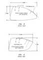
- FIG. 7is a 2D cross sectional view of a golf club in the prior art.
- FIG. 8is a 2D cross sectional view of an alternative golf club in the prior art.
- FIG. 9is a 2D cross sectional view of a second alternative golf club in the prior art.
- the present inventionrelates to the design relationships and methods of measurement comprising the improved aspect ratio of the driver golf club head 20 and the improved driver golf club head 20 crown 26 surface design.
- LTCMLarge Tangent Circle Method
- the LTCM orientationis achieved by bringing the golf club head 20 into a Cartesian Coordinate System (CCS) space where three perpendicular planes exist.
- CCSCartesian Coordinate System
- the point at which all three planes intersect each otheris called the origin point, as shown in FIG. 3 .
- the resulting lines of intersection of the three planes with each otherare perpendicular lines representing the CCS, with each line or axis being labeled appropriately X, Y, and Z and pass through the origin point.
- the values on either side of the origin of the X, Y, and Z axisare labeled either positive or negative, as defined and understood in the CCS.
- the driver golf club head 20is oriented in such a manner such that the hosel axis line 32 lies in the YZ plane and passes through the origin point of the CCS.
- the driver golf club head 20is further oriented such that the hosel axis line 32 of the golf club head 20 lies at an angle equal to its designed lie angle from the ⁇ Y axis rotating around the origin point towards the +Z axis, using the right-hand rule with the thumb pointing in the ⁇ X direction.
- the golf club head 20is further oriented by pivoting it around the hosel axis line 32 until a point or edge on the sole 28 is tangent to a plane parallel with the XY plane that has the greatest intersection point value on the Z axis.
- the crown silhouette curve 34 and the sole silhouette curve 36are projected onto a measurement plane parallel to the YZ plane.
- a circle 38is placed on the measurement plane between the projected crown silhouette curve 34 and the projected sole silhouette curve 36 and is enlarged until the circle 38 has the maximum diameter possible, preferably to the nearest 0.001 inch, and is tangent to both the projected crown silhouette curve 34 and the projected sole silhouette curve 36 .
- a tangent line 40is created from the tangent point where the circle touches the projected crown silhouette curve 34 to the tangent point where the circle touches the projected sole silhouette curve 36 .
- a cross sectional curve 43of the golf club head 20 is obtained by orienting a plane 41 though the tangent line 40 connecting the tangent points and rotating the plane through the tangent line 40 so the cross section curve 43 is created with the XY plane that is parallel with the X axis of the CCS.
- the created and oriented planeis used to intersect the golf club head 20 to obtain 2D cross-sectional views showing the crown 26 contour of the driver type golf club head 20 .
- An area encompassed by a rectangle having a preferred height of 0.25 inch and a preferred length of 1.00 inch,is positioned approximately 0.030 inch above, in the +Z direction, and 0.800 inch to the right, in the +X direction, of the uppermost intersection curve with the face 30 of the golf club head 20 .
- the rectangular area, or crown apex zone 42is an important zone for the surface of the crown 26 of the golf club head 20 , and has its highest point, the apex point 46 . It is further away from the face 30 of the golf club head 20 , in the +X direction, and relatively not too high above the upper edge of the face 30 , in the +Y direction. When the apex point 46 of the surface of the crown 26 falls within this zone 42 , the airflow moving across the surface of the crown 26 of the golf club head 20 has been shown to remain laminar and reduce the drag of the driver type golf club head 20 .
- the new methods used to improve aerodynamic properties of a driver golf club head 20involve the relationship that the apex point 46 on the crown 26 surface of a club head 20 has with other geometric features on the club head 20 , such as its depth, height and curvature of the crown 26 surface.
- the present inventioncomprises two methods of enhancing the swing characteristics of a driver club head 20 by reducing the drag force.
- the method of the present inventioninvolves creating a driver type golf club head 20 that has an increased depth, distance from the face 30 to the most rearward point, while reducing its height. This improves air flow over the face 30 and crown 26 of the driver type golf club head 20 , which minimizes the overall projected area of the club head 20 in the direction of the airflow.
- An alternative method of the present inventioninvolves creating a driver type golf club head 20 having a crown 26 surface that is flatter, combined with an apex point 46 location that is further away from the face 30 to promote a more preferred air flow over the club head 20 .
- Driver type golf club heads 20 created using the methods discussedenable the golfer to benefit from an improved driver 20 design more suited to hitting shots with higher ball velocities due to the increased head speed produced by lower drag forces opposing the driver 20 as it travels through the air.
- the feature of a flatter crown 26 surfacereduces the drag of the air flow over the crown 26 in a more favorable manner if the of the crown 26 is within the crown apex zone 42 and the crown 26 surface does not drop off too rapidly.
- the drag coefficients over the crown 26 surfaceare reduced resulting in lower drag forces.
- club head 20 depths greater than 4.600 inchesare preferred.
- the projected area of the golf club head 20is also reduced.
- the projected areais a variable in the drag equation, and the lower the area, the better opportunity exists to lower the overall drag of the club head 20 .
- a club height, hthat is less than half the depth, d, of the club head 20
- a projected area shape that is lower in overall area and shallower in aspect ratiois achieved in comparison to projected area shapes of drivers with deeper club heights. This minimizes the displacement of air molecules as they pass over and around the club head 20 . For example if an air molecule hits the center of a driver club 20 face 20 , the distance it has to travel up the face 20 and around the club head 20 is less if the face 30 height is shallower versus the distance it must travel on deeper face 30 driver 20 .
- the apex of the crown 26is located in the rectangular zone, or crown apex zone 42 , and the depth, d, of the club head 20 must be at least twice the length as the height, h, of the club head 20 as measured in the plane defined by the LTCM method.
- the minimum depth, d, of the club head 20must be equal or greater than 4.600 inch.
- the curve of the crown 26is designed to have some portion exist above a 5.25 inch radius arc that begins at the apex point 46 of the curve of the crown 26 and runs towards the back end of the club head 20 , in the +X direction.
- a driver type golf club head 20 formed using the method of the present inventioncomprises a body 22 having a face 30 , a crown 26 and a sole 28 , wherein the crown 26 is located in a crown apex zone 42 .
- the club head 20has a depth, d, the depth being at least twice the length as a height of the club head, wherein the depth is at least 4.600 inches.
- the driver type golf club head 20preferably has a volume of less than 400 cubic centimeters.
- the body 22is preferably composed of a stainless steel material.
- the sole 28is preferably composed of a metal material and the crown 26 is preferably composed of a non-metal material.
- the body 22is alternatively composed of a titanium alloy material.
- FIG. 7-9show golf club heads in the prior art, wherein the design features do not comply with the parameters set forth in the method of the present invention.
- the apex of the crownis located within the desired crown apex zone 42 , the height is more than 50% of the depth.
- FIG. 8shows a golf club head of the prior art wherein the apex point 46 of the crown does not lie within the crown apex zone 42 .
- FIG. 9shows an alternative golf club in the prior art wherein the depth of the club is not equal to or greater than 4.600 inches.
- Galloway, et al., U.S. Pat. No. 7,163,470is hereby incorporated by reference in its entirety.
- Galloway, et al., U.S. Pat. No. 7,258,631is hereby incorporated by reference in its entirety.
Landscapes
- Health & Medical Sciences (AREA)
- General Health & Medical Sciences (AREA)
- Physical Education & Sports Medicine (AREA)
- Life Sciences & Earth Sciences (AREA)
- Engineering & Computer Science (AREA)
- Wood Science & Technology (AREA)
- Golf Clubs (AREA)
Abstract
Description
Claims (6)
Priority Applications (2)
| Application Number | Priority Date | Filing Date | Title |
|---|---|---|---|
| US13/023,778US8574096B2 (en) | 2010-02-10 | 2011-02-09 | Golf club head with improved aerodynamic characteristics |
| US14/048,855US8696493B2 (en) | 2010-02-10 | 2013-10-08 | Golf club head with improved aerodynamic characteristics |
Applications Claiming Priority (2)
| Application Number | Priority Date | Filing Date | Title |
|---|---|---|---|
| US30317510P | 2010-02-10 | 2010-02-10 | |
| US13/023,778US8574096B2 (en) | 2010-02-10 | 2011-02-09 | Golf club head with improved aerodynamic characteristics |
Related Child Applications (1)
| Application Number | Title | Priority Date | Filing Date |
|---|---|---|---|
| US14/048,855ContinuationUS8696493B2 (en) | 2010-02-10 | 2013-10-08 | Golf club head with improved aerodynamic characteristics |
Publications (2)
| Publication Number | Publication Date |
|---|---|
| US20110195800A1 US20110195800A1 (en) | 2011-08-11 |
| US8574096B2true US8574096B2 (en) | 2013-11-05 |
Family
ID=44354151
Family Applications (2)
| Application Number | Title | Priority Date | Filing Date |
|---|---|---|---|
| US13/023,778Active2032-02-25US8574096B2 (en) | 2010-02-10 | 2011-02-09 | Golf club head with improved aerodynamic characteristics |
| US14/048,855ActiveUS8696493B2 (en) | 2010-02-10 | 2013-10-08 | Golf club head with improved aerodynamic characteristics |
Family Applications After (1)
| Application Number | Title | Priority Date | Filing Date |
|---|---|---|---|
| US14/048,855ActiveUS8696493B2 (en) | 2010-02-10 | 2013-10-08 | Golf club head with improved aerodynamic characteristics |
Country Status (1)
| Country | Link |
|---|---|
| US (2) | US8574096B2 (en) |
Cited By (2)
| Publication number | Priority date | Publication date | Assignee | Title |
|---|---|---|---|---|
| US8622849B1 (en)* | 2010-02-10 | 2014-01-07 | Callaway Golf Company | Golf club head with improved aerodynamic characteristics |
| US8696493B2 (en)* | 2010-02-10 | 2014-04-15 | Callaway Golf Company | Golf club head with improved aerodynamic characteristics |
Families Citing this family (1)
| Publication number | Priority date | Publication date | Assignee | Title |
|---|---|---|---|---|
| JP2023540265A (en)* | 2020-08-26 | 2023-09-22 | カーステン マニュファクチュアリング コーポレーション | A club head with balanced impact performance characteristics and swing performance characteristics |
Citations (14)
| Publication number | Priority date | Publication date | Assignee | Title |
|---|---|---|---|---|
| US6402639B1 (en)* | 1999-10-28 | 2002-06-11 | Mizuno Corporation | Metal wood club head |
| US7163470B2 (en) | 2004-06-25 | 2007-01-16 | Callaway Golf Company | Golf club head |
| US7163468B2 (en) | 2005-01-03 | 2007-01-16 | Callaway Golf Company | Golf club head |
| US7166038B2 (en) | 2005-01-03 | 2007-01-23 | Callaway Golf Company | Golf club head |
| US7214143B2 (en) | 2005-03-18 | 2007-05-08 | Callaway Golf Company | Golf club head with a face insert |
| US7252600B2 (en) | 1999-11-01 | 2007-08-07 | Callaway Golf Company | Multiple material golf club head |
| US7258626B2 (en) | 2004-10-07 | 2007-08-21 | Callaway Golf Company | Golf club head with variable face thickness |
| US7273419B2 (en) | 2004-09-10 | 2007-09-25 | Callaway Golf Company | Multiple material golf club head |
| US7462109B2 (en)* | 2004-09-10 | 2008-12-09 | Callaway Golf Company | Multiple material golf club head |
| US8083609B2 (en)* | 2008-07-15 | 2011-12-27 | Adams Golf Ip, Lp | High volume aerodynamic golf club head |
| US8088021B2 (en)* | 2008-07-15 | 2012-01-03 | Adams Golf Ip, Lp | High volume aerodynamic golf club head having a post apex attachment promoting region |
| US8241142B2 (en)* | 2010-07-16 | 2012-08-14 | Callaway Golf Company | Golf club head with improved aerodynamic characteristics |
| US8510927B2 (en)* | 2010-02-10 | 2013-08-20 | Callaway Golf Company | Method of forming a golf club head with improved aerodynamic charcteristics |
| US8516675B2 (en)* | 2010-02-10 | 2013-08-27 | Callaway Golf Company | Method of forming a golf club head with improved aerodynamic characteristics |
Family Cites Families (8)
| Publication number | Priority date | Publication date | Assignee | Title |
|---|---|---|---|---|
| US6669580B1 (en)* | 1997-10-23 | 2003-12-30 | Callaway Golf Company | Golf club head that optimizes products of inertia |
| US7549935B2 (en)* | 2005-01-03 | 2009-06-23 | Callaway Golf Company | Golf club head |
| US7488261B2 (en)* | 2005-01-03 | 2009-02-10 | Callaway Golf Company | Golf club with high moment of inertia |
| US7568982B2 (en)* | 2005-01-03 | 2009-08-04 | Callaway Golf Company | Golf club with high moment of inertia |
| US7591737B2 (en)* | 2005-01-03 | 2009-09-22 | Callaway Golf Company | Golf club head |
| US7559851B2 (en)* | 2005-01-03 | 2009-07-14 | Callaway Golf Company | Golf club with high moment of inertia |
| US8172697B2 (en)* | 2009-08-17 | 2012-05-08 | Callaway Golf Company | Selectively lightened wood-type golf club head |
| US8574096B2 (en)* | 2010-02-10 | 2013-11-05 | Callaway Golf Company | Golf club head with improved aerodynamic characteristics |
- 2011
- 2011-02-09USUS13/023,778patent/US8574096B2/enactiveActive
- 2013
- 2013-10-08USUS14/048,855patent/US8696493B2/enactiveActive
Patent Citations (17)
| Publication number | Priority date | Publication date | Assignee | Title |
|---|---|---|---|---|
| US6402639B1 (en)* | 1999-10-28 | 2002-06-11 | Mizuno Corporation | Metal wood club head |
| US7252600B2 (en) | 1999-11-01 | 2007-08-07 | Callaway Golf Company | Multiple material golf club head |
| US7163470B2 (en) | 2004-06-25 | 2007-01-16 | Callaway Golf Company | Golf club head |
| US7258631B2 (en) | 2004-06-25 | 2007-08-21 | Callaway Golf Company | Golf club head |
| US7462109B2 (en)* | 2004-09-10 | 2008-12-09 | Callaway Golf Company | Multiple material golf club head |
| US7273419B2 (en) | 2004-09-10 | 2007-09-25 | Callaway Golf Company | Multiple material golf club head |
| US7258626B2 (en) | 2004-10-07 | 2007-08-21 | Callaway Golf Company | Golf club head with variable face thickness |
| US7163468B2 (en) | 2005-01-03 | 2007-01-16 | Callaway Golf Company | Golf club head |
| US7166038B2 (en) | 2005-01-03 | 2007-01-23 | Callaway Golf Company | Golf club head |
| US7214143B2 (en) | 2005-03-18 | 2007-05-08 | Callaway Golf Company | Golf club head with a face insert |
| US8083609B2 (en)* | 2008-07-15 | 2011-12-27 | Adams Golf Ip, Lp | High volume aerodynamic golf club head |
| US8088021B2 (en)* | 2008-07-15 | 2012-01-03 | Adams Golf Ip, Lp | High volume aerodynamic golf club head having a post apex attachment promoting region |
| US8540586B1 (en)* | 2008-07-15 | 2013-09-24 | Taylor Made Golf Company, Inc. | High volume aerodynamic golf club head having a post apex attachment promoting region |
| US8510927B2 (en)* | 2010-02-10 | 2013-08-20 | Callaway Golf Company | Method of forming a golf club head with improved aerodynamic charcteristics |
| US8516675B2 (en)* | 2010-02-10 | 2013-08-27 | Callaway Golf Company | Method of forming a golf club head with improved aerodynamic characteristics |
| US8241142B2 (en)* | 2010-07-16 | 2012-08-14 | Callaway Golf Company | Golf club head with improved aerodynamic characteristics |
| US8317636B2 (en)* | 2010-07-16 | 2012-11-27 | Callaway Golf Company | Golf club head with improved aerodynamic characteristics |
Cited By (2)
| Publication number | Priority date | Publication date | Assignee | Title |
|---|---|---|---|---|
| US8622849B1 (en)* | 2010-02-10 | 2014-01-07 | Callaway Golf Company | Golf club head with improved aerodynamic characteristics |
| US8696493B2 (en)* | 2010-02-10 | 2014-04-15 | Callaway Golf Company | Golf club head with improved aerodynamic characteristics |
Also Published As
| Publication number | Publication date |
|---|---|
| US8696493B2 (en) | 2014-04-15 |
| US20110195800A1 (en) | 2011-08-11 |
| US20140045610A1 (en) | 2014-02-13 |
Similar Documents
| Publication | Publication Date | Title |
|---|---|---|
| US8241142B2 (en) | Golf club head with improved aerodynamic characteristics | |
| US8622849B1 (en) | Golf club head with improved aerodynamic characteristics | |
| US10463929B2 (en) | Golf club head with stepped crown | |
| US9956459B2 (en) | Golf club assembly and golf club with aerodynamic features | |
| US8864601B1 (en) | Golf club head with improved aerodynamic characteristics | |
| TWI432242B (en) | Golf club assembly and golf club with aerodynamic hosel | |
| TWI473632B (en) | Golf club assembly and golf club with aerodynamic body (1) | |
| US9375617B2 (en) | Golf club assembly and golf club with aerodynamic features | |
| US8678946B2 (en) | Golf club assembly and golf club with aerodynamic features | |
| KR101881170B1 (en) | Golf club set | |
| US8646163B2 (en) | Method of forming a golf club head with improved aerodynamic characteristics | |
| US8510927B2 (en) | Method of forming a golf club head with improved aerodynamic charcteristics | |
| JP2008188366A (en) | Golf club head | |
| JP5882522B1 (en) | Golf club head | |
| US8516675B2 (en) | Method of forming a golf club head with improved aerodynamic characteristics | |
| JP2023540265A (en) | A club head with balanced impact performance characteristics and swing performance characteristics | |
| US8696493B2 (en) | Golf club head with improved aerodynamic characteristics | |
| JP2016107022A (en) | Golf club head | |
| JP2013000237A (en) | Golf club head | |
| US10188914B2 (en) | Golf club head |
Legal Events
| Date | Code | Title | Description |
|---|---|---|---|
| AS | Assignment | Owner name:CALLAWAY GOLF COMPANY, CALIFORNIA Free format text:ASSIGNMENT OF ASSIGNORS INTEREST;ASSIGNORS:EVANS, D. CLAYTON;GIBBS, EVAN D.;CACKETT, MATTHEW T.;AND OTHERS;SIGNING DATES FROM 20110126 TO 20110204;REEL/FRAME:025776/0506 | |
| STCF | Information on status: patent grant | Free format text:PATENTED CASE | |
| FPAY | Fee payment | Year of fee payment:4 | |
| AS | Assignment | Owner name:BANK OF AMERICA, N.A., CALIFORNIA Free format text:SECURITY INTEREST;ASSIGNORS:CALLAWAY GOLF COMPANY;CALLAWAY GOLF SALES COMPANY;CALLAWAY GOLF BALL OPERATIONS, INC.;AND OTHERS;REEL/FRAME:045350/0741 Effective date:20171120 | |
| AS | Assignment | Owner name:BANK OF AMERICA, N.A., AS ADMINISTRATIVE AGENT, NO Free format text:SECURITY AGREEMENT;ASSIGNORS:CALLAWAY GOLF COMPANY;OGIO INTERNATIONAL, INC.;REEL/FRAME:048172/0001 Effective date:20190104 Owner name:BANK OF AMERICA, N.A., AS ADMINISTRATIVE AGENT, NORTH CAROLINA Free format text:SECURITY AGREEMENT;ASSIGNORS:CALLAWAY GOLF COMPANY;OGIO INTERNATIONAL, INC.;REEL/FRAME:048172/0001 Effective date:20190104 | |
| AS | Assignment | Owner name:BANK OF AMERICA, N.A., CALIFORNIA Free format text:SECURITY INTEREST;ASSIGNORS:CALLAWAY GOLF COMPANY;CALLAWAY GOLF SALES COMPANY;CALLAWAY GOLF BALL OPERATIONS, INC.;AND OTHERS;REEL/FRAME:048110/0352 Effective date:20190104 | |
| MAFP | Maintenance fee payment | Free format text:PAYMENT OF MAINTENANCE FEE, 8TH YEAR, LARGE ENTITY (ORIGINAL EVENT CODE: M1552); ENTITY STATUS OF PATENT OWNER: LARGE ENTITY Year of fee payment:8 | |
| AS | Assignment | Owner name:OGIO INTERNATIONAL, INC., CALIFORNIA Free format text:RELEASE (REEL 048172 / FRAME 0001);ASSIGNOR:BANK OF AMERICA, N.A.;REEL/FRAME:063622/0187 Effective date:20230316 Owner name:TOPGOLF CALLAWAY BRANDS CORP. (F/K/A CALLAWAY GOLF COMPANY), CALIFORNIA Free format text:RELEASE (REEL 048172 / FRAME 0001);ASSIGNOR:BANK OF AMERICA, N.A.;REEL/FRAME:063622/0187 Effective date:20230316 | |
| AS | Assignment | Owner name:BANK OF AMERICA, N.A, AS COLLATERAL AGENT, NORTH CAROLINA Free format text:SECURITY AGREEMENT;ASSIGNORS:TOPGOLF CALLAWAY BRANDS CORP. (FORMERLY CALLAWAY GOLF COMPANY);OGIO INTERNATIONAL, INC.;TOPGOLF INTERNATIONAL, INC.;AND OTHERS;REEL/FRAME:063665/0176 Effective date:20230512 | |
| AS | Assignment | Owner name:BANK OF AMERICA, N.A., CALIFORNIA Free format text:SECURITY INTEREST;ASSIGNORS:TOPGOLF CALLAWAY BRANDS CORP.;OGIO INTERNATIONAL, INC.;TOPGOLF INTERNATIONAL, INC.;AND OTHERS;REEL/FRAME:063692/0009 Effective date:20230517 | |
| MAFP | Maintenance fee payment | Free format text:PAYMENT OF MAINTENANCE FEE, 12TH YEAR, LARGE ENTITY (ORIGINAL EVENT CODE: M1553); ENTITY STATUS OF PATENT OWNER: LARGE ENTITY Year of fee payment:12 |