US8573801B2 - LED illuminator - Google Patents
LED illuminatorDownload PDFInfo
- Publication number
- US8573801B2 US8573801B2US13/234,259US201113234259AUS8573801B2US 8573801 B2US8573801 B2US 8573801B2US 201113234259 AUS201113234259 AUS 201113234259AUS 8573801 B2US8573801 B2US 8573801B2
- Authority
- US
- United States
- Prior art keywords
- light
- light source
- wavelength range
- optical element
- dichroic
- Prior art date
- Legal status (The legal status is an assumption and is not a legal conclusion. Google has not performed a legal analysis and makes no representation as to the accuracy of the status listed.)
- Active, expires
Links
- 230000003287optical effectEffects0.000claimsabstractdescription88
- 238000005286illuminationMethods0.000claimsabstractdescription21
- 239000000463materialSubstances0.000claimsdescription23
- 239000000835fiberSubstances0.000claimsdescription22
- 230000002708enhancing effectEffects0.000abstractdescription3
- 238000000034methodMethods0.000description13
- 230000004907fluxEffects0.000description12
- 239000004065semiconductorSubstances0.000description11
- 210000004127vitreous bodyAnatomy0.000description10
- OAICVXFJPJFONN-UHFFFAOYSA-NPhosphorusChemical compound[P]OAICVXFJPJFONN-UHFFFAOYSA-N0.000description8
- 238000000576coating methodMethods0.000description8
- 238000001228spectrumMethods0.000description8
- 238000010586diagramMethods0.000description7
- 239000011248coating agentSubstances0.000description6
- 229910052736halogenInorganic materials0.000description6
- 150000002367halogensChemical class0.000description6
- 239000013307optical fiberSubstances0.000description6
- 238000004064recyclingMethods0.000description6
- 210000001525retinaAnatomy0.000description6
- 239000002775capsuleSubstances0.000description5
- 239000000523sampleSubstances0.000description5
- 239000000758substrateSubstances0.000description5
- WFKWXMTUELFFGS-UHFFFAOYSA-NtungstenChemical compound[W]WFKWXMTUELFFGS-UHFFFAOYSA-N0.000description5
- 229910052721tungstenInorganic materials0.000description5
- 239000010937tungstenSubstances0.000description5
- 210000003786scleraAnatomy0.000description4
- 238000001356surgical procedureMethods0.000description4
- 208000002367Retinal PerforationsDiseases0.000description3
- 239000003086colorantSubstances0.000description3
- 210000004087corneaAnatomy0.000description3
- 210000001747pupilAnatomy0.000description3
- 239000000126substanceSubstances0.000description3
- 206010025421MaculeDiseases0.000description2
- 206010038897Retinal tearDiseases0.000description2
- 206010064930age-related macular degenerationDiseases0.000description2
- 210000003484anatomyAnatomy0.000description2
- 238000013459approachMethods0.000description2
- 210000001742aqueous humorAnatomy0.000description2
- 210000004556brainAnatomy0.000description2
- 238000006243chemical reactionMethods0.000description2
- 210000004240ciliary bodyAnatomy0.000description2
- 208000002780macular degenerationDiseases0.000description2
- 229910001507metal halideInorganic materials0.000description2
- 150000005309metal halidesChemical class0.000description2
- 230000004048modificationEffects0.000description2
- 238000012986modificationMethods0.000description2
- 210000001328optic nerveAnatomy0.000description2
- 230000008569processEffects0.000description2
- 239000007787solidSubstances0.000description2
- 229910019655synthetic inorganic crystalline materialInorganic materials0.000description2
- 102000008186CollagenHuman genes0.000description1
- 108010035532CollagenProteins0.000description1
- 206010048843Cytomegalovirus chorioretinitisDiseases0.000description1
- 206010012689Diabetic retinopathyDiseases0.000description1
- 208000001351Epiretinal MembraneDiseases0.000description1
- 229910002601GaNInorganic materials0.000description1
- JMASRVWKEDWRBT-UHFFFAOYSA-NGallium nitrideChemical compound[Ga]#NJMASRVWKEDWRBT-UHFFFAOYSA-N0.000description1
- 208000031471Macular fibrosisDiseases0.000description1
- 206010038848Retinal detachmentDiseases0.000description1
- 229920002385Sodium hyaluronatePolymers0.000description1
- 241000278713TheoraSpecies0.000description1
- 208000034698Vitreous haemorrhageDiseases0.000description1
- 230000003466anti-cipated effectEffects0.000description1
- 230000002238attenuated effectEffects0.000description1
- 230000008901benefitEffects0.000description1
- 230000005540biological transmissionEffects0.000description1
- 229910019990cerium-doped yttrium aluminum garnetInorganic materials0.000description1
- 229920001436collagenPolymers0.000description1
- 238000010276constructionMethods0.000description1
- 208000001763cytomegalovirus retinitisDiseases0.000description1
- 230000007423decreaseEffects0.000description1
- 230000003247decreasing effectEffects0.000description1
- 230000002950deficientEffects0.000description1
- 238000013461designMethods0.000description1
- 238000011161developmentMethods0.000description1
- 230000018109developmental processEffects0.000description1
- 206010012601diabetes mellitusDiseases0.000description1
- 230000000694effectsEffects0.000description1
- 230000005670electromagnetic radiationEffects0.000description1
- 210000000871endothelium cornealAnatomy0.000description1
- 239000012530fluidSubstances0.000description1
- 230000006872improvementEffects0.000description1
- 229910052738indiumInorganic materials0.000description1
- APFVFJFRJDLVQX-UHFFFAOYSA-Nindium atomChemical compound[In]APFVFJFRJDLVQX-UHFFFAOYSA-N0.000description1
- 238000001802infusionMethods0.000description1
- 210000003041ligamentAnatomy0.000description1
- 238000004020luminiscence typeMethods0.000description1
- 210000002189macula luteaAnatomy0.000description1
- 208000029233macular holesDiseases0.000description1
- 210000003205muscleAnatomy0.000description1
- 230000003387muscularEffects0.000description1
- 210000005036nerveAnatomy0.000description1
- 210000003733optic diskAnatomy0.000description1
- 239000002245particleSubstances0.000description1
- 210000000184posterior capsule of the lenAnatomy0.000description1
- 230000004264retinal detachmentEffects0.000description1
- 230000002207retinal effectEffects0.000description1
- 230000035939shockEffects0.000description1
- 229940010747sodium hyaluronateDrugs0.000description1
- YWIVKILSMZOHHF-QJZPQSOGSA-Nsodium;(2s,3s,4s,5r,6r)-6-[(2s,3r,4r,5s,6r)-3-acetamido-2-[(2s,3s,4r,5r,6r)-6-[(2r,3r,4r,5s,6r)-3-acetamido-2,5-dihydroxy-6-(hydroxymethyl)oxan-4-yl]oxy-2-carboxy-4,5-dihydroxyoxan-3-yl]oxy-5-hydroxy-6-(hydroxymethyl)oxan-4-yl]oxy-3,4,5-trihydroxyoxane-2-Chemical compound[Na+].CC(=O)N[C@H]1[C@H](O)O[C@H](CO)[C@@H](O)[C@@H]1O[C@H]1[C@H](O)[C@@H](O)[C@H](O[C@H]2[C@@H]([C@@H](O[C@H]3[C@@H]([C@@H](O)[C@H](O)[C@H](O3)C(O)=O)O)[C@H](O)[C@@H](CO)O2)NC(C)=O)[C@@H](C(O)=O)O1YWIVKILSMZOHHF-QJZPQSOGSA-N0.000description1
- 230000002792vascularEffects0.000description1
- XLYOFNOQVPJJNP-UHFFFAOYSA-NwaterSubstancesOXLYOFNOQVPJJNP-UHFFFAOYSA-N0.000description1
Images


Classifications
- A—HUMAN NECESSITIES
- A61—MEDICAL OR VETERINARY SCIENCE; HYGIENE
- A61B—DIAGNOSIS; SURGERY; IDENTIFICATION
- A61B90/00—Instruments, implements or accessories specially adapted for surgery or diagnosis and not covered by any of the groups A61B1/00 - A61B50/00, e.g. for luxation treatment or for protecting wound edges
- A61B90/30—Devices for illuminating a surgical field, the devices having an interrelation with other surgical devices or with a surgical procedure
- A—HUMAN NECESSITIES
- A61—MEDICAL OR VETERINARY SCIENCE; HYGIENE
- A61B—DIAGNOSIS; SURGERY; IDENTIFICATION
- A61B3/00—Apparatus for testing the eyes; Instruments for examining the eyes
- A61B3/0008—Apparatus for testing the eyes; Instruments for examining the eyes provided with illuminating means
- A—HUMAN NECESSITIES
- A61—MEDICAL OR VETERINARY SCIENCE; HYGIENE
- A61F—FILTERS IMPLANTABLE INTO BLOOD VESSELS; PROSTHESES; DEVICES PROVIDING PATENCY TO, OR PREVENTING COLLAPSING OF, TUBULAR STRUCTURES OF THE BODY, e.g. STENTS; ORTHOPAEDIC, NURSING OR CONTRACEPTIVE DEVICES; FOMENTATION; TREATMENT OR PROTECTION OF EYES OR EARS; BANDAGES, DRESSINGS OR ABSORBENT PADS; FIRST-AID KITS
- A61F9/00—Methods or devices for treatment of the eyes; Devices for putting in contact-lenses; Devices to correct squinting; Apparatus to guide the blind; Protective devices for the eyes, carried on the body or in the hand
- A61F9/007—Methods or devices for eye surgery
Definitions
- an eyemay be divided into two distinct parts—an anterior segment and a posterior segment.
- the anterior segmentincludes a lens and extends from an outermost layer of the cornea (the corneal endothelium) to a posterior of a lens capsule.
- the posterior segmentincludes a portion of the eye behind the lens capsule.
- the posterior segmentextends from an anterior hyaloid face (part of a vitreous body) to a retina, with which a posterior hyaloid face is in direct contact.
- the posterior segmentis much larger than the anterior segment.
- the posterior segmentincludes the vitreous body—a clear, colorless, gel-like substance. It makes up approximately two-thirds of the eye's volume, giving it form and shape before birth.
- the vitreous bodyis composed of 1% collagen and sodium hyaluronate and 99% water.
- the anterior boundary of the vitreous bodyis the anterior hyaloid face, which touches the posterior capsule of the lens, while the posterior hyaloid face forms its posterior boundary, and is in contact with the retina.
- the vitreous bodyis not free flowing like the aqueous humor and has normal anatomic attachment sites. One of these sites is the vitreous base, which is an approximately 3-4 mm wide band that overlies the ora serrata.
- the optic nerve head, macula lutea, and vascular arcadeare also sites of attachment.
- the vitreous body's major functionsare to hold the retina in place, maintain the integrity and shape of the globe, absorb shock due to movement, and to give support for the lens posteriorly.
- the vitreous bodyis not continuously replaced.
- the vitreous bodybecomes more fluid with age in a process known as syneresis. Syneresis results in shrinkage of the vitreous body, which can exert pressure or traction on its normal attachment sites. If enough traction is applied, the vitreous body may pull itself from its retinal attachment and create a retinal tear or hole.
- Vitreo-retinal proceduresare commonly performed in the posterior segment of the eye. Vitreo-retinal procedures are appropriate to treat many serious conditions of the posterior segment. Vitreo-retinal procedures treat conditions such as age-related macular degeneration (AMD), diabetic retinopathy and diabetic vitreous hemorrhage, macular hole, retinal detachment, epiretinal membrane, CMV retinitis, and many other ophthalmic conditions.
- AMDage-related macular degeneration
- diabetic retinopathy and diabetic vitreous hemorrhagemacular hole
- retinal detachmentepiretinal membrane
- CMV retinitisCMV retinitis
- a surgeonperforms vitreo-retinal procedures with a microscope and special lenses designed to provide a clear image of the posterior segment. Several tiny incisions just a millimeter or so in length are made on the sclera at the pars plana. The surgeon inserts microsurgical instruments through the incisions, such as a fiber optic light source, to illuminate inside the eye; an infusion line to maintain the eye's shape during surgery; and instruments to cut and remove the vitreous body.
- microsurgical instrumentsthrough the incisions, such as a fiber optic light source, to illuminate inside the eye; an infusion line to maintain the eye's shape during surgery; and instruments to cut and remove the vitreous body.
- a thin optical fiberis inserted into the eye to provide the illumination.
- a light sourcesuch as a halogen tungsten lamp or high pressure arc lamp (metal-halides, Xe) may be used to produce the light carried by the optical fiber into the eye.
- the lightpasses through several optical elements (typically lenses, mirrors, and attenuators) and is transmitted to the optical fiber that carries the light into the eye.
- the advantage of arc lampsis a small emitting area ( ⁇ 1 mm), a color temperature close to daylight, and typically a longer life than halogen lamps (i.e., 400 hours vs. 50 hours).
- the disadvantage of arc lampsis high cost, decline in power, complexity of the systems and the need to exchange lamps several times over the life of the system.
- LEDslight emitting diodes
- LED based illuminatorsmay be provided at considerably lower cost and complexity, and may exhibit characteristic life times of 50,000 to 100,000 hours, which may enable operating an ophthalmic fiber illuminator for the entire life of the instrument with very little drop in output and without the need to replace LEDs.
- LED light sourcesgenerally exhibit lower luminous efficiency and decreased luminous flux than comparable halogen tungsten lamps and high pressure are lamps.
- FIG. 1is a cross-sectional view of an eye illustrating its internal anatomy
- FIG. 2is a schematic illustration of an exemplary illumination probe that may be employed with an endoilluminator, shown illuminating an interior region of the eye of FIG. 1 ;
- FIG. 3is a schematic partial cross-sectional view of an exemplary illuminator that may be employed with an endoilluminator for supplying light to the illumination probe of FIG. 2 ;
- FIG. 4is a schematic illustration of an exemplary undomed light emitting diode (LED) that may be employed with the illuminator of FIG. 3 ;
- LEDlight emitting diode
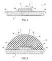
- FIG. 5is a schematic illustration of an exemplary domed light emitting diode (LED) that may be employed with the illuminator of FIG. 3 ;
- LEDlight emitting diode
- FIG. 6is a chromaticity diagram graphically depicting an exemplary relative effect that certain individual features of the illuminator of FIG. 3 may have on chromaticity;
- FIG. 7is a schematic partial cross-sectional view of the exemplary domed LED of FIG. 5 employed with a reflective optical element;
- FIG. 8is a schematic partial cross-sectional view of the exemplary undomed LED of FIG. 4 employed with a reflective optical element
- FIG. 9is a chromaticity diagram graphically depicting relative changes in chromaticity that may be achieved when employing the exemplary illuminator of FIG. 3 .
- FIG. 1illustrates an anatomy of an eye 20 , which includes a cornea 22 , an iris 24 , a pupil 26 , a lens 28 , a lens capsule 30 , zonules 32 , ciliary body 34 , sclera 36 , vitreous region 38 , retina 40 , macula 42 , and optic nerve 44 .
- Cornea 22is a clear, dome shaped structure on the surface of eye 20 that acts as a window, letting light into the eye.
- Iris 24which corresponds to the colored part of the eye, is a muscle surrounding pupil 26 that relaxes and contracts to control the amount of light entering eye 20 .
- Pupil 26is a round, central opening in iris 24 .
- Lens 28is a structure inside eye 20 that helps focus light on retina 40 .
- Lens capsule 30is an elastic bag that encapsulates lens 30 , helping to control the shape of lens 28 as the eye focuses on objects at different distances.
- Zonules 32are slender ligaments that attach lens capsule 30 to the inside of eye 20 , holding lens 28 in place.
- Ciliary body 34is a muscular area attached to lens 28 that contracts and relaxes to control the size of the lens for focusing.
- Sclera 36is a tough, outermost layer of eye 20 that maintains the shape of the eye.
- Vitreous region 38is a large, gel-filled section located towards a back of eye 20 that helps maintain the curvature of the eye.
- Retina 40is a light-sensitive nerve layer at the back of eye 20 that receives light and converts it into signals to send to the brain.
- Macula 42is an area in the back of eye 20 that includes receptors for detecting fine detail in a viewed image.
- Optic nerve 44transmits signals from eye 20 to the brain.
- an ophthalmic endoilluminator 46 for illuminating an interior of eye 20is shown inserted through sclera 36 into vitreous region 38 .
- Endoilluminator 46may include a handpiece 48 and a probe 50 .
- Probe 50may include a fiber optic cable 52 for transferring light from an illuminator to illuminate the inside of vitreous region 38 of eye 20 during various intra-optical procedures, such as vitreo-retinal surgery.
- Endoilluminator 46may employ various light sources, for example, halogen tungsten lamps and high-pressure arc lamp (metal-halides and Xe). Light emitting diodes (LEDs) may also be employed as a light source for endoilluminator 46 . LEDs may provide considerably lower cost and complexity than comparable halogen tungsten lamps and high-pressure arc lamps. LEDs may have characteristic life times of 50,000-100,000 hours, which would enable operating ophthalmic endoilluminator 46 for the life of the instrument with minimal drop in output and without a need for replacing LEDs.
- LEDsLight emitting diodes
- endoilluminator 46may employ an illuminator 54 for producing light at a particular luminous flux and chromaticity.
- Light generated by illuminator 54may be transmitted to probe 50 through fiber optic cable 52 , which may have an end 56 optically connected to illuminator 54 .
- the exemplary configuration shown in FIG. 3employs a first light channel 55 and a second light channel 57 .
- First light channel 55includes a first light source 58
- second light channel 57includes a second light source 60 .
- Additional light sourcesmay also be employed depending on the design requirements of a particular application.
- Light sources 58 and 60may be similarly configured or have different configurations.
- Light source 58may include one or more LEDs configured to emit a generally broad-spectrum white light.
- the LEDsmay be manufactured in a variety of configurations.
- An exemplarily configured LED 62is illustrated in FIG. 4 .
- LED 62may be produced by coating a generally monochromatic LED die 64 , with a wavelength converting material 65 capable of converting electromagnetic radiation, in a particular range of the electromagnetic spectrum, to another range within the electromagnetic spectrum, including but not limited to, the conversion of high-energy particle rays, x-rays and UV to lower energy photons. Any suitable type of wavelength converting material or substance may be employed.
- the luminescence process utilized for conversionmay be based on either slow emission (Phosphorescence) or fast emission (fluorescence), depending on the type of wavelength converting materials employed.
- LED die 64generally emits light within a relatively narrow range of wavelengths, such as ultraviolet (UV), violet, or blue light, depending on the semiconductor diode material employed.
- Indium Gallium Nitride (InGaN)generally produces a blue light having a wavelength ( ⁇ ) of approximately 450 nm ⁇ 500 nm.
- the relatively narrow light bandis generally not suitable for illumination.
- the emitted spectrummay be tailored by employing, for example, phosphor of different colors as wavelength converting material 65 to produce light across a desired spectrum. The number and type of phosphor coatings employed may be varied to produce light within a desired wavelength range.
- a phosphor material that may be employed with a blue semiconductor diode material to produce a generally broad-spectrum white lightis cerium doped yttrium aluminum garnet (Ce 3+ :YAG).
- the phosphor coatingcauses a portion of the blue light emitted from LED die 64 to undergo a Stokes shift.
- the Stokes-shifted lightemits at a higher wavelength range tending toward the yellow spectrum than the blue light emitted directly from the InGaN semiconductor. Not all of the blue light emitted from the semiconductor undergoes a Stokes-shift. Unconverted blue light and the Stokes-shifted light combine to produce light that appears generally as broadband white light.
- the phosphor coating for converting a portion of the blue light emitted from LED die 64 to a higher wavelength lightmay be deposited on a surface 80 of the LED die. This is merely one example of various semiconductor/phosphor combinations that may be employed to produce a broadband white light.
- LED die 64may be electrically connected to a cathode 66 and an anode 68 .
- LED die 64 , cathode 66 and anode 68may be supported on a substrate 72 . Applying an electrical current to cathode 66 and anode 68 causes LED die 64 to emit light within a wavelength range corresponding to the semiconductor diode material employed.
- LEDs employed with light source 58may also be configured to include a lens for further controlling the light emitted from the light source. LEDs employing a lens may be referred to as “domed” LEDs.
- An example of a domed LED 81is illustrated in FIG. 5 . Domed LED 81 may have as similar configuration as undomed LED 62 shown in FIG. 4 , but with the addition of a lens 82 attached to LED die 64 . Materials used to make wavelength converting material 65 typically have high refractive indices, which may result in a portion of the light directly emitted from LED die 64 being reflected back onto the LED (i.e., recycled) at the wavelength converting material/air surface interface (i.e., surface 83 of wavelength converting material 65 ).
- Recycling light produced by LED die 64may cause a shift in the chromaticity of the light emitted from the LED towards the yellow spectrum (for example, when employing Ce 3+ :YAG as the phosphor) due to a portion of the recycled light undergoing a Stokes shift.
- Light recyclingmay be reduced by attaching lens 82 to undomed LED 62 to produce domed LED 81 .
- Lens 82includes a convex outer surface 84 that tends to reduce light recycling within domed LED 81 .
- unconverted lightFor convenience, light having a wavelength range produced by LED die 64 shall hereinafter be referred to as “unconverted light”, whereas light having a wavelength within the range of the Stokes-shifted light emitted from the phosphor coating (i.e., wavelength converting material 65 ) shall herein after be referred to as “converted light”. Furthermore, light having a wavelength within the range produced by LED die 64 (i.e., unconverted light) is represented throughout the figures by a solid line, and light having a wavelength within the range of the Stokes-shifted light (i.e., converted light) is represented throughout the figures by a small dashed line.
- light channel 55may include various features for enhancing the light flux emitted from the light channel, and for controlling the size and direction of a corresponding light beam.
- light channel 55may include one or more reflective optical elements 86 arranged adjacent to light source 58 .
- Reflective optical element 86may be configured as a broadband reflector to reflect both converted and unconverted light back toward light source 58 .
- Reflective optical element 86is generally spaced apart from light source 58 , and may have a generally concave shape relative to light source 58 .
- Reflective optical element 86includes a first circumferential edge defining a proximal end 88 , and second circumferential edge defining an opposite distal end 90 .
- Proximal end 88may be arranged axially along an optical axis 92 in a general vicinity of light source 58 .
- Distal end 90may be arranged along optical axis 92 at a an axial distance from light source 58 that is greater than an axial distance between proximal end 88 and light source 58 . Due to the curvature of reflective optical element 86 , a radial distance between proximal end 88 and optical axis 92 is greater than a radial distance between distal end 90 and optical axis 92 .
- Dichroic mirror 96may be configured to allow converted light to pass through dichroic mirror 96 , and to reflect unconverted light back toward light source 58 .
- Reflective optical element 86 and dichroic mirror 96together operate to enhance the light flux emitted from light channel 55 , which may improve the operating efficiency of illuminator 54 .
- Dichroic mirror 96 and reflective optical element 86also operate together to direct converted light out through opening 94 in reflective optical element 86 .
- Dichroic mirror 96may have a generally concave shape relative to light source 58 .
- dichroic mirror 96may be configured as a substantially spherical reflector having a center of curvature arranged along outer surface 83 of wavelength converting material 65 and generally centered relative to LED die 64 .
- Dichroic mirror 96is generally displaced away from light source 58 .
- substantially the entire dichroic mirror 96is positioned at a distance further from light source 58 than distal end 90 of reflective optical element 86 .
- Dichroic mirror 96may also be positioned at other locations along optical axis 92 relative to distal end 90 of reflective optical element 86 , which may include positions that are closer or further away from light source 58 . For example, all or a portion of dichroic mirror 96 may be positioned along optical axis 92 between light source 58 and distal end 90 of reflective optical element 86 . Dichroic mirror 96 may be sized so as not to overlap reflective optical element 86 , as shown in FIG. 3 , or may be sized to overlap reflective optical element 86 , in which case an edge 98 of dichroic mirror 96 would be at a further distance from optical axis 92 than distal end 90 of reflective optical element 86 . First reflective optical element 86 and dichroic mirror 94 may also be integrally formed, for example, by applying optical coatings associated with the individual optical elements to a continuous uninterrupted substrate material.
- undomed LED 62may enhance the luminous flux emitted from light channel 55 , but may also cause a shift in the chromaticity of light emitted from light channel 55 toward the yellow wavelength ranges, as opposed to a similar configuration, for example, employing domed LED 81 without reflective optical element 86 .
- operating an LED without a lensmay cause a shift in the wavelength of the emitted light toward the yellow wavelength ranges due to recycling of a portion of the light emitted from LED die 64 .
- Employing reflective optical element 86 with either undomed LED 62 ( FIG. 4 ) or domed LED 81 ( FIG. 5 )also tends to cause a shift in the chromaticity of light emitted from light channel 55 toward the yellow wavelength ranges.
- a representative shift in chromaticity that may occur when employing reflective optical element 86 with either undomed LED 62 or domed LED 81is reflected on a chromaticity diagram show in FIG. 6 . Included in the chromaticity diagram is a CIE 1931 color space identifying the range of colors typically visible to a human eye. An exemplary chromaticity of light emitted from domed LED 81 ( FIG. 5 ) is indicated on the chromaticity chart as a solid black square. An exemplary chromaticity of light emitted from undomed LED 62 ( FIG. 4 ) is indicated on the chromaticity chart as an unfilled square. Employing reflective optical element 86 ( FIG. 3 ) with domed LED 81 , for example, as shown in FIG.
- undomed LED 62may increase recycling of light emitted from the corresponding LED, resulting in a shift in chromaticity of the emitted light toward the yellow frequency range.
- An exemplary chromaticity of light emitted from domed LED 81 when used in connection with reflective optical element 86 ( FIG. 7 )is indicated on the chromaticity chart as a solid black triangle.
- An exemplary chromaticity of light emitted from undomed LED 62 when used in connection with reflective optical element 86 ( FIG. 8 )is indicated on the chromaticity chart as an unfilled triangle.
- Employing reflective optical element 86 with domed LED 81 and undomed LED 62 in both instanceswill generally produce a measurable shift in chromaticity of light emitted from light channel 55 toward the yellow wavelength ranges.
- the chromaticity shifting of light emitted from light channel 55 toward yellow wavelength ranges when employing undomed LED 62 and/or reflective optical element 86may be at least partially attenuated by employing second light channel 57 , which includes second light source 60 .
- light source 60may include one or more LEDs configured to emit a narrow band blue light.
- the light emitted from second light source 60will generally be at a similar wavelength range as the light blocked by dichroic mirror 96 .
- the LED employed with light source 60may be manufactured in a variety of configurations, examples of which are shown in FIGS. 4 and 5 .
- LED die 64may be selected to generally emit light within a similar wavelength range as the semiconductor diode material employed with light source 58 . This may be accomplished by employing the same semiconductor diode material for both light sources 58 and 60 , or alternatively, by employing different semiconductor materials that emit light within similar wavelength ranges. Unlike the LED employed with light source 58 , the LED employed with light source 60 generally does not employ a wavelength converting material or substance for converting the light emitted from the semiconductor diode material to another wavelength range, since the light emitted from light channel 57 will generally have the same wavelength range as the light emitted from the semiconductor diode material employed with light source 58 .
- light channel 57may include various features for enhancing the luminous flux emitted from light channel 57 , and for controlling the size and direction of a corresponding light beam.
- light channel 57may include one or more second reflective optical elements 100 arranged adjacent to light source 60 .
- Reflective optical element 100may be configured as a broadband or narrow band reflector with sufficient bandwidth to reflect substantially all of the light arriving at the reflector back toward light source 60 .
- Reflective optical element 100is generally spaced apart from light source 60 , and may have a generally concave shape relative to light source 60 .
- Reflective optical element 100may include a first circumferential edge defining a proximal end 102 and a second circumferential edge defining an opposite distal end 104 .
- Proximal end 102may be arranged axially along an optical axis 106 in a general vicinity of light source 60 .
- Distal end 104may be arranged along optical axis 106 at an axial distance from light source 60 that is greater than an axial distance between proximal end 102 and light source 60 . Due to the curvature of reflective optical element 100 , a radial distance between proximal end 102 and optical axis 106 is greater than a radial distance between distal end 104 and optical axis 106 .
- reflective optical element 100may include an optically transparent opening 108 though which light produced by light source 60 may be emitted from light channel 57 .
- Opening 108may be configured as an aperture extending completely through reflective optical element 100 , as shown in FIG. 3 .
- opening 108may be formed by providing a region corresponding to opening 108 over which no reflective coating is applied to a substantially optically clear substrate of reflective optical element 100 . In the latter configuration, the optically clear substrate of reflective optical element 100 will cover opening 108 , but since the region corresponding to opening 108 is devoid of a reflective coating, light emitted from light source 60 would be able to pass through the uncoated substrate material.
- Light source 60may emit light over a wide angle.
- reflective optical element 100may operate to redirect at least a portion of the light emitted from light source 60 that exceeds a selected emission angle ⁇ back towards light source 60 . This enables the portion of light emitted form light source 60 at an emission angle greater than a selected maximum to be recycled within light channel 57 and redirected through opening 108 in reflective optical element 100 . Recycling at least a portion of the light emitted from light source 60 may increase the light flux emitted from light channel 57 .
- Illuminator 54may include one or more optical elements for combining the yellow shifted broad-spectrum light beam emitted from light channel 55 with the narrow blue spectrum light beam emitted from light channel 57 into a single broad-spectrum white light beam suitable for delivery to fiber optic cable 52 .
- Fiber optic cable 52generally includes a single optical fiber, although multiple optical fibers may also be employed.
- Fiber optic cable 52typically includes a maximum emission angle 110 , which is an angle relative to a fiber axis 112 at which light may enter the fiber optic wire and travel along its length.
- a numerical aperture (NA)may be determined for fiber optic cable 52 based on the fiber's maximum emission angle. The NA corresponds to the sine of the fiber optic cable's maximum emission angle.
- optical elements for optically connecting light channels 55 and 57 to fiber optic cable 52may be configure to achieve a numerical aperture compatible with the numerical aperture of fiber optic cable 52 . This helps ensure that light delivered to fiber optic cable 52 will be able to enter and travel along fiber optic cable 52 .
- a first collimating lens 114receives a diverging light beam emitted from light channel 55 .
- Light passing through collimating lens 114is refracted to form a generally collimated light beam.
- the maximum incidence angle ⁇ of the light beam arriving at collimating lens 114 from light channel 55may be at least partially controlled by varying the size of opening 94 in reflective optical element 86 .
- the maximum incidence anglegenerally increases with increasing size of opening 94 .
- a second collimating lens 116receives a diverging light beam emitted from light channel 57 . Light passing through second collimating lens 116 is refracted to form a generally collimated light beam.
- the maximum incidence angle ⁇ of the light beam arriving at collimating lens 116 from light channel 57may be at least partially controlled by varying the size of opening 108 in reflective optical element 100 . The maximum incidence angle generally increases with increasing size of opening 108 .
- Illuminator 54may include a dichroic filter 118 for combining the broad-spectrum yellow shifted light beam emitted from light channel 55 with the narrow blue spectrum light beam emitted from light channel 57 to form a single collimated broad-spectrum white light beam.
- Dichroic filter 118may be arranged downstream of first collimating lens 114 and second collimating lens 116 .
- Dichroic filter 118may be configured to selectively pass light falling within the wavelength range of light emitted from light channel 55 , while reflecting light falling within the wavelength range of light emitted from light channel 57 .
- the collimated light beam from first collimating lens 114passes through dichroic filter 118 , whereas the collimated light beam from second collimating lens 116 is reflected from dichroic filter 118 , thereby enabling the two separate light beams to combine and form a single collimated light beam that generally appears as a broad-spectrum white light.
- the resulting broad-spectrum white light beamis represented in FIG. 3 by long dashed lines.
- the collimated broad-spectrum white light beam from dichroic filter 118passes through a condensing lens 120 , which operates to focus the collimated light beam for delivery to fiber optic cable 52 .
- FIG. 3illustrates merely one example of an optical arrangement for combining the light emitted from light channel 55 with the light emitted from light channel 57 , and focusing the resulting light beam for transmission to fiber optic cable 52 .
- Other arrangementsmay also be employed.
- Configuration Agenerally consists of LED light source 58 configured as undomed LED 62 ( FIG.
- “Configuration B”is similar to “Configuration A”, but also includes dichroic mirror 96 .
- “Configuration C”is substantially the configuration illustrated in FIG. 3 . Assuming a light flux of 100 percent for “Configuration A”, adding dichroic mirror 96 to “Configuration A” to arrive at “Configuration B” may produce an exemplary increase in luminous flux of approximately 1.8 percent, but also produces a corresponding shift in chromaticity towards longer yellow wavelengths. Modifying “Configuration B” to include light channel 57 and dichroic filter 118 may result in a 9.2 percent increase in luminous flux, as compared to “Configuration A”, while at same time shifting chromaticity significantly toward the white light wavelengths.
Landscapes
- Health & Medical Sciences (AREA)
- Life Sciences & Earth Sciences (AREA)
- Surgery (AREA)
- Heart & Thoracic Surgery (AREA)
- Molecular Biology (AREA)
- Veterinary Medicine (AREA)
- Engineering & Computer Science (AREA)
- Biomedical Technology (AREA)
- Public Health (AREA)
- Medical Informatics (AREA)
- General Health & Medical Sciences (AREA)
- Animal Behavior & Ethology (AREA)
- Pathology (AREA)
- Nuclear Medicine, Radiotherapy & Molecular Imaging (AREA)
- Oral & Maxillofacial Surgery (AREA)
- Physics & Mathematics (AREA)
- Biophysics (AREA)
- Ophthalmology & Optometry (AREA)
- Non-Portable Lighting Devices Or Systems Thereof (AREA)
Abstract
Description
Claims (13)
Priority Applications (7)
| Application Number | Priority Date | Filing Date | Title |
|---|---|---|---|
| US13/234,259US8573801B2 (en) | 2010-08-30 | 2011-09-16 | LED illuminator |
| EP12831719.5AEP2741657A4 (en) | 2011-09-16 | 2012-08-24 | Led illuminator |
| JP2014530678AJP2014530665A (en) | 2011-09-16 | 2012-08-24 | LED illuminator |
| AU2012309072AAU2012309072A1 (en) | 2011-09-16 | 2012-08-24 | Led illuminator |
| CN201280051837.8ACN103889315A (en) | 2011-09-16 | 2012-08-24 | Led illuminator |
| PCT/US2012/052200WO2013039669A1 (en) | 2011-09-16 | 2012-08-24 | Led illuminator |
| CA2848352ACA2848352A1 (en) | 2011-09-16 | 2012-08-24 | Led illuminator |
Applications Claiming Priority (3)
| Application Number | Priority Date | Filing Date | Title |
|---|---|---|---|
| US37820610P | 2010-08-30 | 2010-08-30 | |
| US201113208974A | 2011-08-12 | 2011-08-12 | |
| US13/234,259US8573801B2 (en) | 2010-08-30 | 2011-09-16 | LED illuminator |
Related Parent Applications (1)
| Application Number | Title | Priority Date | Filing Date |
|---|---|---|---|
| US201113208974AContinuation-In-Part | 2010-08-30 | 2011-08-12 |
Publications (2)
| Publication Number | Publication Date |
|---|---|
| US20120051042A1 US20120051042A1 (en) | 2012-03-01 |
| US8573801B2true US8573801B2 (en) | 2013-11-05 |
Family
ID=47883611
Family Applications (1)
| Application Number | Title | Priority Date | Filing Date |
|---|---|---|---|
| US13/234,259Active2032-05-24US8573801B2 (en) | 2010-08-30 | 2011-09-16 | LED illuminator |
Country Status (7)
| Country | Link |
|---|---|
| US (1) | US8573801B2 (en) |
| EP (1) | EP2741657A4 (en) |
| JP (1) | JP2014530665A (en) |
| CN (1) | CN103889315A (en) |
| AU (1) | AU2012309072A1 (en) |
| CA (1) | CA2848352A1 (en) |
| WO (1) | WO2013039669A1 (en) |
Cited By (5)
| Publication number | Priority date | Publication date | Assignee | Title |
|---|---|---|---|---|
| US9188307B2 (en) | 2013-12-17 | 2015-11-17 | Ephesus Lighting, Inc. | High intensity LED illumination device with automated sensor-based control |
| US9730302B2 (en) | 2015-12-28 | 2017-08-08 | Ephesus Lighting, Inc. | System and method for control of an illumination device |
| US9849034B2 (en) | 2011-11-07 | 2017-12-26 | Alcon Research, Ltd. | Retinal laser surgery |
| US9857066B2 (en) | 2015-12-28 | 2018-01-02 | Ephesus Lighting, Inc. | LED illumination device with single pressure cavity |
| US10161619B2 (en) | 2015-12-28 | 2018-12-25 | Eaton Intelligent Power Limited | LED illumination device with vent to heat sink |
Families Citing this family (15)
| Publication number | Priority date | Publication date | Assignee | Title |
|---|---|---|---|---|
| US10197224B1 (en) | 2012-05-17 | 2019-02-05 | Colt International Clothing Inc. | Multicolored tube light with improved LED array |
| US9719642B1 (en) | 2012-05-17 | 2017-08-01 | Colt International Clothing Inc. | Tube light with improved LED array |
| US9107728B2 (en)* | 2012-09-23 | 2015-08-18 | Mark Philip Breazzano | Eyeball stabilizing apparatus and method of use |
| CN103647015A (en)* | 2013-12-18 | 2014-03-19 | 吴震 | Light-emitting diode encapsulation structure and light emitting device |
| CN103822140A (en)* | 2014-02-12 | 2014-05-28 | 吴震 | Light source with light emitting diode, projection display light source and projection display light machine |
| CN103822141A (en)* | 2014-02-12 | 2014-05-28 | 吴震 | Light source with light emitting diode, projection display light source and projection display light machine |
| DE102014221263A1 (en)* | 2014-10-20 | 2016-04-21 | Alamedics Gmbh & Co. Kg | Device for illuminating the intraocular space |
| WO2016102354A1 (en)* | 2014-12-22 | 2016-06-30 | Ge Healthcare Bio-Sciences Ab | Improvements in and relating to led illumination in microscopy |
| RU168079U1 (en)* | 2016-04-05 | 2017-01-17 | Федеральное государственное бюджетное образовательное учреждение высшего профессионального образования "Казанский государственный энергетический университет" (ФГБОУ ВПО "КГЭУ") | DEVICE FOR IDENTIFICATION OF OBJECT IN COAGENT LIGHT |
| RU2629716C1 (en)* | 2016-04-18 | 2017-08-31 | Федеральное государственное бюджетное образовательное учреждение высшего профессионального образования "Казанский государственный энергетический университет" (ФГБОУ ВПО "КГЭУ") | Method for identifying object in coherent light |
| CN107450274B (en)* | 2016-05-31 | 2019-03-26 | 上海微电子装备(集团)股份有限公司 | Lamp optical system and the lithographic equipment for using the lamp optical system |
| JP2018084602A (en)* | 2016-11-21 | 2018-05-31 | オリンパス株式会社 | Epi-light illumination optics for microscope, and microscope |
| US10939815B2 (en) | 2016-11-21 | 2021-03-09 | Alcon Inc. | Systems and methods using a vitreous visualization tool |
| US10537401B2 (en)* | 2016-11-21 | 2020-01-21 | Novartis Ag | Vitreous visualization system and method |
| NL2022322B1 (en)* | 2018-12-28 | 2020-07-23 | Crea Ip B V | Light source for ophthalmic applications |
Citations (121)
| Publication number | Priority date | Publication date | Assignee | Title |
|---|---|---|---|---|
| US3026559A (en) | 1958-11-13 | 1962-03-27 | Sanymetal Products Company Inc | Door operating hinge assembly |
| US4222375A (en) | 1978-03-10 | 1980-09-16 | Miguel Martinez | In vivo illumination system utilizing a cannula with a conical opening allowing a snap-fit with a conical lens and an aperture for flow of fluids and utilizing a housing with a spherical lens for focusing light onto fiber optics |
| US4656508A (en) | 1984-06-08 | 1987-04-07 | Olympus Optical Co., Ltd. | Measuring endoscope |
| US4870952A (en) | 1983-10-28 | 1989-10-03 | Miquel Martinez | Fiber optic illuminator for use in surgery |
| US4883333A (en) | 1987-10-13 | 1989-11-28 | Yanez Serge J | Integrated, solid, optical device |
| US4884133A (en) | 1987-06-11 | 1989-11-28 | Olympus Optical Co., Ltd. | Endoscope light source apparatus |
| US5086378A (en) | 1990-08-20 | 1992-02-04 | Prince Mark W | Fiber optic finger light |
| US5301090A (en) | 1992-03-16 | 1994-04-05 | Aharon Z. Hed | Luminaire |
| US5420768A (en) | 1993-09-13 | 1995-05-30 | Kennedy; John | Portable led photocuring device |
| US5465170A (en) | 1993-01-19 | 1995-11-07 | Atr Optical And Radio Communications Research Lab. | Alignment adjusting system for use in optical system of optical transceiver |
| US5526190A (en) | 1994-09-29 | 1996-06-11 | Xerox Corporation | Optical element and device for providing uniform irradiance of a surface |
| US5591160A (en) | 1993-09-24 | 1997-01-07 | Reynard; Michael | Fiber optic sleeve for surgical instruments |
| US5598042A (en) | 1993-09-22 | 1997-01-28 | The Watt Stopper | Moveable desktop load controller |
| US5657116A (en) | 1994-10-19 | 1997-08-12 | Canon Kabushiki Kaisha | Ocular lens measuring apparatus |
| US5736410A (en) | 1992-09-14 | 1998-04-07 | Sri International | Up-converting reporters for biological and other assays using laser excitation techniques |
| US5830139A (en) | 1996-09-04 | 1998-11-03 | Abreu; Marcio M. | Tonometer system for measuring intraocular pressure by applanation and/or indentation |
| US5859693A (en) | 1997-08-26 | 1999-01-12 | Laser Technology, Inc. | Modularized laser-based survey system |
| US5997163A (en) | 1998-06-09 | 1999-12-07 | L E Systems Inc. | Mobile laser spotlight system for law enforcement |
| US6000813A (en) | 1996-12-21 | 1999-12-14 | Krietzman; Mark Howard | Laser pointer with light shaping rotating disk |
| US6015403A (en) | 1996-02-26 | 2000-01-18 | Alcon Laboratories, Inc. | Ophthalmic surgery probe with soft tip |
| US6036683A (en) | 1997-01-02 | 2000-03-14 | G. Rodenstock Instruments Gmbh | Process and apparatus for changing the curvature of the cornea |
| US6102696A (en) | 1999-04-30 | 2000-08-15 | Osterwalder; J. Martin | Apparatus for curing resin in dentistry |
| US6120460A (en) | 1996-09-04 | 2000-09-19 | Abreu; Marcio Marc | Method and apparatus for signal acquisition, processing and transmission for evaluation of bodily functions |
| USD434753S (en) | 1998-09-21 | 2000-12-05 | Scientific-Atlanta, Inc. | Light emitting diode module |
| US6183086B1 (en) | 1999-03-12 | 2001-02-06 | Bausch & Lomb Surgical, Inc. | Variable multiple color LED illumination system |
| US6190022B1 (en) | 1995-08-23 | 2001-02-20 | Science & Engineering Associates, Inc. | Enhanced non-lethal visual security device |
| US6211626B1 (en) | 1997-08-26 | 2001-04-03 | Color Kinetics, Incorporated | Illumination components |
| US6217188B1 (en) | 1999-03-04 | 2001-04-17 | Ani-Motion, Inc. | Color changeable fiber-optic illuminated display |
| US6226126B1 (en) | 1998-11-25 | 2001-05-01 | Advanced Laser Technologies, Inc. | Light beam mixer |
| US6268613B1 (en) | 1999-03-02 | 2001-07-31 | Phormax Corporation | Multiple-head phosphor screen scanner |
| US6270244B1 (en) | 1999-11-16 | 2001-08-07 | Dn Labs Inc | Fiber optic illumination system having diffraction grating wavelength selector |
| US6272269B1 (en) | 1999-11-16 | 2001-08-07 | Dn Labs Inc. | Optical fiber/waveguide illumination system |
| US20010052930A1 (en) | 1997-10-06 | 2001-12-20 | Adair Edwin L. | Reduced area imaging device incorporated within wireless endoscopic devices |
| US6336904B1 (en) | 1998-04-07 | 2002-01-08 | Pro Duct Health, Inc. | Methods and devices for the localization of lesions in solid tissue |
| US20020003928A1 (en) | 1999-04-19 | 2002-01-10 | Gemfire Corporation | Optically integrating pixel microstructure |
| US20020087149A1 (en) | 2001-01-03 | 2002-07-04 | Mccary Brian Douglas | Ophthalmic illumination device |
| US6431731B1 (en) | 1999-03-15 | 2002-08-13 | Mark Howard Krietzman | Laser device and method for producing diffuse illumination |
| US6436035B1 (en) | 1999-04-06 | 2002-08-20 | Duke University | Intensity controllable hand-held surgical light |
| US20020137984A1 (en) | 2001-03-22 | 2002-09-26 | Ashwani Chhibber | Endoscopic intubation system |
| US6459844B1 (en) | 1998-10-30 | 2002-10-01 | Jds Uniphase Corporation | Tunable fiber optic filter |
| EP1114608B1 (en) | 2000-01-07 | 2003-03-26 | Nidek Co., Ltd. | Eye observation apparatus having a plurality of individually controlled LEDs for colour corrected illumination |
| US20030112421A1 (en) | 1999-07-01 | 2003-06-19 | Asml Netherlands B.V. | Apparatus and method of image enhancement through spatial filtering |
| US20030132701A1 (en) | 2001-11-01 | 2003-07-17 | Nichia Corporation | Light emitting apparatus provided with fluorescent substance and semiconductor light emitting device, and method of manufacturing the same |
| US20030147254A1 (en) | 2001-12-04 | 2003-08-07 | Kenji Yoneda | Light radiation device, light source device, light radiation unit, and light connection mechanism |
| US20030169603A1 (en) | 2002-03-05 | 2003-09-11 | Luloh K. Peter | Apparatus and method for illuminating a field of view within an eye |
| US20030223249A1 (en) | 2002-06-03 | 2003-12-04 | Tae-Jin Lee | Liquid crystal display device having a noise shielding member |
| US20030223248A1 (en) | 2002-06-04 | 2003-12-04 | Cronin Paul J. | Multispectral imaging system |
| US20040004846A1 (en) | 2002-07-03 | 2004-01-08 | Steen Mark E. | Light source for ophthalmic use |
| US6730940B1 (en) | 2002-10-29 | 2004-05-04 | Lumileds Lighting U.S., Llc | Enhanced brightness light emitting device spot emitter |
| US20040124429A1 (en) | 2002-12-31 | 2004-07-01 | Edward Stokes | Layered phosphor coatings for led devices |
| US20040233655A1 (en) | 2003-05-23 | 2004-11-25 | Scott Moore Zimmerman | Illumination systems utilizing highly reflective light emitting diodes and light recycling to enhance brightness |
| US20050018309A1 (en) | 2003-05-22 | 2005-01-27 | Mcguire James R. | Apparatus and methods for illuminating optical systems |
| US20050024587A1 (en) | 2003-08-01 | 2005-02-03 | Visx, Incorporated | Slit lamp for ophthalmic use |
| US20050047172A1 (en) | 2003-08-28 | 2005-03-03 | Ulrich Sander | Light-emitting diode illumination system for an optical observation device, in particular a stereomicroscope or stereo surgical microscope |
| US20050063171A1 (en) | 2003-09-10 | 2005-03-24 | Armin Leitel | Illumination module for color display |
| US20050099824A1 (en) | 2000-08-04 | 2005-05-12 | Color Kinetics, Inc. | Methods and systems for medical lighting |
| US6893258B1 (en) | 2002-06-11 | 2005-05-17 | Cms-Dental Aps | Dental material curing apparatus |
| US20050110808A1 (en) | 2003-11-25 | 2005-05-26 | Goldschmidt Alan B. | Method and system for LED temporal dithering to achieve multi-bit color resolution |
| US20050140270A1 (en) | 2003-12-02 | 2005-06-30 | Henson Gordon D. | Solid state light device |
| US20050190562A1 (en) | 2004-02-27 | 2005-09-01 | Lumileds Lighting U.S., Llc | Illumination system with aligned LEDs |
| US6960872B2 (en) | 2003-05-23 | 2005-11-01 | Goldeneye, Inc. | Illumination systems utilizing light emitting diodes and light recycling to enhance output radiance |
| US20050243539A1 (en) | 2002-03-26 | 2005-11-03 | Evans Gareth P | Cooled light emitting apparatus |
| US20050270775A1 (en) | 2004-06-04 | 2005-12-08 | Lumileds Lighting U.S., Llc | Remote wavelength conversion in an illumination device |
| JP2006087764A (en) | 2004-09-27 | 2006-04-06 | Kyocera Corp | LED fiber light source device and endoscope using the same |
| US7025464B2 (en) | 2004-03-30 | 2006-04-11 | Goldeneye, Inc. | Projection display systems utilizing light emitting diodes and light recycling |
| US20060203468A1 (en) | 2004-03-30 | 2006-09-14 | Goldeneye, Inc. | Light recycling illumination systems with wavelength conversion |
| US20060262272A1 (en) | 2000-12-21 | 2006-11-23 | Orthoscopics Limited | Apparatus and method for application of tinted light and concurrent assessment of performance |
| US20070102033A1 (en) | 2005-11-04 | 2007-05-10 | Universal Media Systems, Inc. | Dynamic heat sink for light emitting diodes |
| US20070133211A1 (en) | 2002-05-17 | 2007-06-14 | Kenji Yoneda | Light emitting diode unit and method for manufacturing light emitting diode unit |
| US7234820B2 (en)* | 2005-04-11 | 2007-06-26 | Philips Lumileds Lighting Company, Llc | Illuminators using reflective optics with recycling and color mixing |
| US20070213618A1 (en) | 2006-01-17 | 2007-09-13 | University Of Washington | Scanning fiber-optic nonlinear optical imaging and spectroscopy endoscope |
| US20070219417A1 (en) | 2003-03-20 | 2007-09-20 | Welch Allyn, Inc. | Electrical adapter for medical diagnostic instruments using replaceable LEDs as illumination sources |
| US7276737B2 (en) | 2003-07-31 | 2007-10-02 | Philips Lumileds Lighting Company, Llc | Light emitting devices with improved light extraction efficiency |
| US7301271B2 (en) | 2003-04-15 | 2007-11-27 | Luminus Devices, Inc. | Light-emitting devices with high light collimation |
| US20070273290A1 (en) | 2004-11-29 | 2007-11-29 | Ian Ashdown | Integrated Modular Light Unit |
| US20070284597A1 (en) | 2006-05-29 | 2007-12-13 | Toyoda Gosei Co., Ltd. | Light emitting device and LCD backlighting device |
| US20070291491A1 (en) | 2006-06-13 | 2007-12-20 | Li Kenneth K | Illumination system and method for recycling light to increase the brightness of the light source |
| US7325957B2 (en) | 2005-01-25 | 2008-02-05 | Jabil Circuit, Inc. | Polarized light emitting diode (LED) color illumination system and method for providing same |
| US7344279B2 (en) | 2003-12-11 | 2008-03-18 | Philips Solid-State Lighting Solutions, Inc. | Thermal management methods and apparatus for lighting devices |
| US7349163B2 (en) | 2001-12-06 | 2008-03-25 | Fraen Corporation S.R.L. | High-heat-dissipation lighting module |
| US20080073616A1 (en) | 2004-08-04 | 2008-03-27 | Intematix Corporation | Novel phosphor systems for a white light emitting diode (LED) |
| US20080112153A1 (en) | 2006-11-15 | 2008-05-15 | Fujifilm Corporation | Planar lighting device |
| US20080144169A1 (en) | 2006-12-14 | 2008-06-19 | Cytyc Corporation | Illumination source for stained biological samples |
| US7403680B2 (en) | 2003-12-02 | 2008-07-22 | 3M Innovative Properties Company | Reflective light coupler |
| US20080175002A1 (en) | 2007-01-23 | 2008-07-24 | Michael Papac | System and method for the removal of undesired wavelengths from light |
| US20080208006A1 (en) | 2004-09-24 | 2008-08-28 | Mina Farr | Opto-electronic illumination and vision module for endoscopy |
| US20080246920A1 (en) | 2007-04-09 | 2008-10-09 | Buczek Mark J | Multi-LED Ophthalmic Illuminator |
| US20080246919A1 (en) | 2007-04-09 | 2008-10-09 | Ron Smith | Ophthalmic Endoilluminator with Hybrid Lens |
| US20080262316A1 (en) | 2004-07-28 | 2008-10-23 | Kyocera Corporation | Light Source Apparatus and Endoscope Provided with Light Source Apparatus |
| WO2008133736A2 (en) | 2006-12-01 | 2008-11-06 | Cubic Corporation | High power laser eye safety protection |
| US20080291682A1 (en) | 2007-05-21 | 2008-11-27 | Light Prescriptions Innovators, Llc | LED luminance-augmentation via specular retroreflection, including collimators that escape the etendue limit |
| US7482636B2 (en) | 2003-10-15 | 2009-01-27 | Nichia Corporation | Light emitting device |
| US20090036955A1 (en) | 2007-08-03 | 2009-02-05 | Xiang Simon Han | Method, System and Apparatus For Guaranteeing Laser Shut-Down Time |
| US20090054957A1 (en) | 2007-07-03 | 2009-02-26 | Iris, Inc | Broad spectrum fiber optic base laser illumination |
| US20090092750A1 (en) | 2007-10-04 | 2009-04-09 | Princo Corp. | Tool for coating an optical disc, method of coating an optical disc, and method for fabricating an optical disc |
| US20090105698A1 (en) | 2007-05-14 | 2009-04-23 | Ams Research Corporation | Medical Laser User Interface |
| US20090154192A1 (en) | 2007-12-17 | 2009-06-18 | Beat Krattiger | Illumination Device For Generating Light And Supplying The Light To An Observation Device Used In Endoscopy Or Microscopy |
| US20090154137A1 (en) | 2007-12-14 | 2009-06-18 | Philips Lumileds Lighting Company, Llc | Illumination Device Including Collimating Optics |
| US20090161358A1 (en)* | 2007-12-19 | 2009-06-25 | Olympus Corporation | Illumination apparatus for cellular analysis apparatus |
| US20090168395A1 (en) | 2007-12-26 | 2009-07-02 | Lumination Llc | Directional linear light source |
| US7556412B2 (en) | 2006-07-20 | 2009-07-07 | Int America, Llc | Fiber optic auxiliary lighting system |
| US20090182313A1 (en) | 2008-01-15 | 2009-07-16 | Jack Robert Auld | Targeted Illumination For Surgical Instrument |
| US20090190371A1 (en) | 2008-01-24 | 2009-07-30 | Optim, Inc. | Monolithic illumination device |
| US20090203966A1 (en) | 2008-02-13 | 2009-08-13 | Fujifilm Corporation | Endoscope light source device |
| US20090219586A1 (en) | 2006-02-23 | 2009-09-03 | Rohm Co., Ltd. | Linear Light Source Device, and Image Reading Device and Planar Display Device Using the Linear Light Source Device |
| US20090227847A1 (en) | 2008-03-07 | 2009-09-10 | John Tepper | Tunable Light Controller |
| US20090267088A1 (en) | 2008-04-24 | 2009-10-29 | Song Peng | Systems, devices and methods of broadband light sources with tunable spectrum |
| US20100100006A1 (en) | 2006-10-26 | 2010-04-22 | Cornell Research Foundation, Inc | Production of optical pulses at a desired wavelength using soliton self-frequency shift |
| US20100127299A1 (en) | 2008-11-25 | 2010-05-27 | Cooper Technologies Company | Actively Cooled LED Lighting System and Method for Making the Same |
| US20100182569A1 (en) | 2009-01-21 | 2010-07-22 | Artsyukhovich Alexander N | Ophthalmic endoillumination using fiber generated light |
| US20100228089A1 (en) | 2008-06-18 | 2010-09-09 | Versatile Power, Inc. | Endoscopic Light Source |
| US20100317923A1 (en) | 2009-06-12 | 2010-12-16 | Fujifilm Corporation | Endoscope system, endoscope, and driving method |
| US20110009752A1 (en) | 2009-07-10 | 2011-01-13 | The Regents Of The University Of California | Endoscopic long range fourier domain optical coherence tomography (lr-fd-oct) |
| US20110037948A1 (en) | 2009-08-12 | 2011-02-17 | Christopher Horvath | White light emitting diode (LED) illuminator for ophthalmic endoillumination |
| US20110037949A1 (en) | 2009-08-12 | 2011-02-17 | Michael James Papac | Ophthalmic endoillumination with thermally isolated phosphor |
| US20110038174A1 (en) | 2009-08-12 | 2011-02-17 | Michael James Papac | Ophthalmic endoillumination with light collector for white phosphor |
| US7918583B2 (en) | 2006-08-16 | 2011-04-05 | Rpc Photonics, Inc. | Illumination devices |
| US20110122366A1 (en) | 2009-11-24 | 2011-05-26 | Smith Ronald T | Single-fiber multi-spot laser probe for ophthalmic endoillumination |
| US20110149591A1 (en) | 2009-12-23 | 2011-06-23 | Smith Ronald T | Enhanced LED illuminator |
| US20110149246A1 (en) | 2009-12-17 | 2011-06-23 | Alexander Artsyukhovich | Photonic lattice LEDs for ophthalmic illumination |
| US7990587B2 (en) | 2004-10-15 | 2011-08-02 | Hoya Corporation | Electronic endoscope having an apparatus for controlling a shading member |
Family Cites Families (3)
| Publication number | Priority date | Publication date | Assignee | Title |
|---|---|---|---|---|
| US8109635B2 (en)* | 2004-08-12 | 2012-02-07 | Ophthalmic Imaging Systems | Integrated retinal imager and method |
| DE102007041439A1 (en)* | 2007-08-28 | 2009-03-05 | Carl Zeiss Surgical Gmbh | Secondary light source |
| WO2012030505A1 (en)* | 2010-08-30 | 2012-03-08 | Alcon Research, Ltd. | Led illuminator |
- 2011
- 2011-09-16USUS13/234,259patent/US8573801B2/enactiveActive
- 2012
- 2012-08-24WOPCT/US2012/052200patent/WO2013039669A1/enactiveApplication Filing
- 2012-08-24CNCN201280051837.8Apatent/CN103889315A/enactivePending
- 2012-08-24EPEP12831719.5Apatent/EP2741657A4/ennot_activeWithdrawn
- 2012-08-24AUAU2012309072Apatent/AU2012309072A1/ennot_activeAbandoned
- 2012-08-24JPJP2014530678Apatent/JP2014530665A/enactivePending
- 2012-08-24CACA2848352Apatent/CA2848352A1/ennot_activeAbandoned
Patent Citations (134)
| Publication number | Priority date | Publication date | Assignee | Title |
|---|---|---|---|---|
| US3026559A (en) | 1958-11-13 | 1962-03-27 | Sanymetal Products Company Inc | Door operating hinge assembly |
| US4222375A (en) | 1978-03-10 | 1980-09-16 | Miguel Martinez | In vivo illumination system utilizing a cannula with a conical opening allowing a snap-fit with a conical lens and an aperture for flow of fluids and utilizing a housing with a spherical lens for focusing light onto fiber optics |
| US4870952A (en) | 1983-10-28 | 1989-10-03 | Miquel Martinez | Fiber optic illuminator for use in surgery |
| US4656508A (en) | 1984-06-08 | 1987-04-07 | Olympus Optical Co., Ltd. | Measuring endoscope |
| US4884133A (en) | 1987-06-11 | 1989-11-28 | Olympus Optical Co., Ltd. | Endoscope light source apparatus |
| US4883333A (en) | 1987-10-13 | 1989-11-28 | Yanez Serge J | Integrated, solid, optical device |
| US5086378A (en) | 1990-08-20 | 1992-02-04 | Prince Mark W | Fiber optic finger light |
| US5301090A (en) | 1992-03-16 | 1994-04-05 | Aharon Z. Hed | Luminaire |
| US5736410A (en) | 1992-09-14 | 1998-04-07 | Sri International | Up-converting reporters for biological and other assays using laser excitation techniques |
| US5465170A (en) | 1993-01-19 | 1995-11-07 | Atr Optical And Radio Communications Research Lab. | Alignment adjusting system for use in optical system of optical transceiver |
| US5634711A (en) | 1993-09-13 | 1997-06-03 | Kennedy; John | Portable light emitting apparatus with a semiconductor emitter array |
| US5420768A (en) | 1993-09-13 | 1995-05-30 | Kennedy; John | Portable led photocuring device |
| US5598042A (en) | 1993-09-22 | 1997-01-28 | The Watt Stopper | Moveable desktop load controller |
| US5591160A (en) | 1993-09-24 | 1997-01-07 | Reynard; Michael | Fiber optic sleeve for surgical instruments |
| US5526190A (en) | 1994-09-29 | 1996-06-11 | Xerox Corporation | Optical element and device for providing uniform irradiance of a surface |
| US5657116A (en) | 1994-10-19 | 1997-08-12 | Canon Kabushiki Kaisha | Ocular lens measuring apparatus |
| US6190022B1 (en) | 1995-08-23 | 2001-02-20 | Science & Engineering Associates, Inc. | Enhanced non-lethal visual security device |
| US6015403A (en) | 1996-02-26 | 2000-01-18 | Alcon Laboratories, Inc. | Ophthalmic surgery probe with soft tip |
| US5830139A (en) | 1996-09-04 | 1998-11-03 | Abreu; Marcio M. | Tonometer system for measuring intraocular pressure by applanation and/or indentation |
| US6213943B1 (en) | 1996-09-04 | 2001-04-10 | Marcio Marc Abreu | Apparatus for signal transmission and detection using a contact device for physical measurement on the eye |
| US6120460A (en) | 1996-09-04 | 2000-09-19 | Abreu; Marcio Marc | Method and apparatus for signal acquisition, processing and transmission for evaluation of bodily functions |
| US6123668A (en) | 1996-09-04 | 2000-09-26 | Abreu; Marcio Marc | Method and apparatus for signal transmission and detection using a contact device |
| US6000813A (en) | 1996-12-21 | 1999-12-14 | Krietzman; Mark Howard | Laser pointer with light shaping rotating disk |
| US6036683A (en) | 1997-01-02 | 2000-03-14 | G. Rodenstock Instruments Gmbh | Process and apparatus for changing the curvature of the cornea |
| US5859693A (en) | 1997-08-26 | 1999-01-12 | Laser Technology, Inc. | Modularized laser-based survey system |
| US6211626B1 (en) | 1997-08-26 | 2001-04-03 | Color Kinetics, Incorporated | Illumination components |
| US20010052930A1 (en) | 1997-10-06 | 2001-12-20 | Adair Edwin L. | Reduced area imaging device incorporated within wireless endoscopic devices |
| US6336904B1 (en) | 1998-04-07 | 2002-01-08 | Pro Duct Health, Inc. | Methods and devices for the localization of lesions in solid tissue |
| US5997163A (en) | 1998-06-09 | 1999-12-07 | L E Systems Inc. | Mobile laser spotlight system for law enforcement |
| USD434753S (en) | 1998-09-21 | 2000-12-05 | Scientific-Atlanta, Inc. | Light emitting diode module |
| US6459844B1 (en) | 1998-10-30 | 2002-10-01 | Jds Uniphase Corporation | Tunable fiber optic filter |
| US6226126B1 (en) | 1998-11-25 | 2001-05-01 | Advanced Laser Technologies, Inc. | Light beam mixer |
| US6268613B1 (en) | 1999-03-02 | 2001-07-31 | Phormax Corporation | Multiple-head phosphor screen scanner |
| US6217188B1 (en) | 1999-03-04 | 2001-04-17 | Ani-Motion, Inc. | Color changeable fiber-optic illuminated display |
| US6183086B1 (en) | 1999-03-12 | 2001-02-06 | Bausch & Lomb Surgical, Inc. | Variable multiple color LED illumination system |
| US6431731B1 (en) | 1999-03-15 | 2002-08-13 | Mark Howard Krietzman | Laser device and method for producing diffuse illumination |
| US6436035B1 (en) | 1999-04-06 | 2002-08-20 | Duke University | Intensity controllable hand-held surgical light |
| US20020003928A1 (en) | 1999-04-19 | 2002-01-10 | Gemfire Corporation | Optically integrating pixel microstructure |
| US6102696A (en) | 1999-04-30 | 2000-08-15 | Osterwalder; J. Martin | Apparatus for curing resin in dentistry |
| US20030112421A1 (en) | 1999-07-01 | 2003-06-19 | Asml Netherlands B.V. | Apparatus and method of image enhancement through spatial filtering |
| US6270244B1 (en) | 1999-11-16 | 2001-08-07 | Dn Labs Inc | Fiber optic illumination system having diffraction grating wavelength selector |
| US6272269B1 (en) | 1999-11-16 | 2001-08-07 | Dn Labs Inc. | Optical fiber/waveguide illumination system |
| EP1114608B1 (en) | 2000-01-07 | 2003-03-26 | Nidek Co., Ltd. | Eye observation apparatus having a plurality of individually controlled LEDs for colour corrected illumination |
| US20050099824A1 (en) | 2000-08-04 | 2005-05-12 | Color Kinetics, Inc. | Methods and systems for medical lighting |
| US20060262272A1 (en) | 2000-12-21 | 2006-11-23 | Orthoscopics Limited | Apparatus and method for application of tinted light and concurrent assessment of performance |
| US20020087149A1 (en) | 2001-01-03 | 2002-07-04 | Mccary Brian Douglas | Ophthalmic illumination device |
| US20020137984A1 (en) | 2001-03-22 | 2002-09-26 | Ashwani Chhibber | Endoscopic intubation system |
| US20030132701A1 (en) | 2001-11-01 | 2003-07-17 | Nichia Corporation | Light emitting apparatus provided with fluorescent substance and semiconductor light emitting device, and method of manufacturing the same |
| US20030147254A1 (en) | 2001-12-04 | 2003-08-07 | Kenji Yoneda | Light radiation device, light source device, light radiation unit, and light connection mechanism |
| US7349163B2 (en) | 2001-12-06 | 2008-03-25 | Fraen Corporation S.R.L. | High-heat-dissipation lighting module |
| US20030169603A1 (en) | 2002-03-05 | 2003-09-11 | Luloh K. Peter | Apparatus and method for illuminating a field of view within an eye |
| US20050243539A1 (en) | 2002-03-26 | 2005-11-03 | Evans Gareth P | Cooled light emitting apparatus |
| US20070133211A1 (en) | 2002-05-17 | 2007-06-14 | Kenji Yoneda | Light emitting diode unit and method for manufacturing light emitting diode unit |
| US20030223249A1 (en) | 2002-06-03 | 2003-12-04 | Tae-Jin Lee | Liquid crystal display device having a noise shielding member |
| US20030223248A1 (en) | 2002-06-04 | 2003-12-04 | Cronin Paul J. | Multispectral imaging system |
| US6893258B1 (en) | 2002-06-11 | 2005-05-17 | Cms-Dental Aps | Dental material curing apparatus |
| US6786628B2 (en) | 2002-07-03 | 2004-09-07 | Advanced Medical Optics | Light source for ophthalmic use |
| US20040090796A1 (en) | 2002-07-03 | 2004-05-13 | Steen Mark E. | Light source for ophthalmic use |
| US7063436B2 (en) | 2002-07-03 | 2006-06-20 | Advanced Medical Optics, Inc. | Light source for ophthalmic use |
| US20040004846A1 (en) | 2002-07-03 | 2004-01-08 | Steen Mark E. | Light source for ophthalmic use |
| US6730940B1 (en) | 2002-10-29 | 2004-05-04 | Lumileds Lighting U.S., Llc | Enhanced brightness light emitting device spot emitter |
| US20040124429A1 (en) | 2002-12-31 | 2004-07-01 | Edward Stokes | Layered phosphor coatings for led devices |
| US6917057B2 (en) | 2002-12-31 | 2005-07-12 | Gelcore Llc | Layered phosphor coatings for LED devices |
| US20070219417A1 (en) | 2003-03-20 | 2007-09-20 | Welch Allyn, Inc. | Electrical adapter for medical diagnostic instruments using replaceable LEDs as illumination sources |
| US7301271B2 (en) | 2003-04-15 | 2007-11-27 | Luminus Devices, Inc. | Light-emitting devices with high light collimation |
| US20050018309A1 (en) | 2003-05-22 | 2005-01-27 | Mcguire James R. | Apparatus and methods for illuminating optical systems |
| US6960872B2 (en) | 2003-05-23 | 2005-11-01 | Goldeneye, Inc. | Illumination systems utilizing light emitting diodes and light recycling to enhance output radiance |
| US20040233655A1 (en) | 2003-05-23 | 2004-11-25 | Scott Moore Zimmerman | Illumination systems utilizing highly reflective light emitting diodes and light recycling to enhance brightness |
| US7276737B2 (en) | 2003-07-31 | 2007-10-02 | Philips Lumileds Lighting Company, Llc | Light emitting devices with improved light extraction efficiency |
| US20050024587A1 (en) | 2003-08-01 | 2005-02-03 | Visx, Incorporated | Slit lamp for ophthalmic use |
| US7229202B2 (en) | 2003-08-28 | 2007-06-12 | Leica Microsystems (Schweiz) Ag | Light-emitting diode illumination system for an optical observation device, in particular a stereomicroscope or stereo surgical microscope |
| US20050047172A1 (en) | 2003-08-28 | 2005-03-03 | Ulrich Sander | Light-emitting diode illumination system for an optical observation device, in particular a stereomicroscope or stereo surgical microscope |
| US20050063171A1 (en) | 2003-09-10 | 2005-03-24 | Armin Leitel | Illumination module for color display |
| US20090095960A1 (en) | 2003-10-15 | 2009-04-16 | Nichia Corporation | Heat dissipation member, semiconductor apparatus and semiconductor light emitting apparatus |
| US7482636B2 (en) | 2003-10-15 | 2009-01-27 | Nichia Corporation | Light emitting device |
| US20050110808A1 (en) | 2003-11-25 | 2005-05-26 | Goldschmidt Alan B. | Method and system for LED temporal dithering to achieve multi-bit color resolution |
| US20050140270A1 (en) | 2003-12-02 | 2005-06-30 | Henson Gordon D. | Solid state light device |
| US7403680B2 (en) | 2003-12-02 | 2008-07-22 | 3M Innovative Properties Company | Reflective light coupler |
| US7344279B2 (en) | 2003-12-11 | 2008-03-18 | Philips Solid-State Lighting Solutions, Inc. | Thermal management methods and apparatus for lighting devices |
| US20050190562A1 (en) | 2004-02-27 | 2005-09-01 | Lumileds Lighting U.S., Llc | Illumination system with aligned LEDs |
| US20060203468A1 (en) | 2004-03-30 | 2006-09-14 | Goldeneye, Inc. | Light recycling illumination systems with wavelength conversion |
| US7025464B2 (en) | 2004-03-30 | 2006-04-11 | Goldeneye, Inc. | Projection display systems utilizing light emitting diodes and light recycling |
| US20050270775A1 (en) | 2004-06-04 | 2005-12-08 | Lumileds Lighting U.S., Llc | Remote wavelength conversion in an illumination device |
| US20080262316A1 (en) | 2004-07-28 | 2008-10-23 | Kyocera Corporation | Light Source Apparatus and Endoscope Provided with Light Source Apparatus |
| US20080073616A1 (en) | 2004-08-04 | 2008-03-27 | Intematix Corporation | Novel phosphor systems for a white light emitting diode (LED) |
| US20080208006A1 (en) | 2004-09-24 | 2008-08-28 | Mina Farr | Opto-electronic illumination and vision module for endoscopy |
| JP2006087764A (en) | 2004-09-27 | 2006-04-06 | Kyocera Corp | LED fiber light source device and endoscope using the same |
| US7990587B2 (en) | 2004-10-15 | 2011-08-02 | Hoya Corporation | Electronic endoscope having an apparatus for controlling a shading member |
| US20070273290A1 (en) | 2004-11-29 | 2007-11-29 | Ian Ashdown | Integrated Modular Light Unit |
| US7325957B2 (en) | 2005-01-25 | 2008-02-05 | Jabil Circuit, Inc. | Polarized light emitting diode (LED) color illumination system and method for providing same |
| US7494228B2 (en) | 2005-04-11 | 2009-02-24 | Philips Lumileds Lighting Company, Llc | Compact mixing cavity for multiple colors of LEDs |
| US20080030984A1 (en) | 2005-04-11 | 2008-02-07 | Philips Lumileds Lighting Company, Llc | Compact Mixing Cavity for Multiple Colors of LEDs |
| US7234820B2 (en)* | 2005-04-11 | 2007-06-26 | Philips Lumileds Lighting Company, Llc | Illuminators using reflective optics with recycling and color mixing |
| US20070102033A1 (en) | 2005-11-04 | 2007-05-10 | Universal Media Systems, Inc. | Dynamic heat sink for light emitting diodes |
| US20070213618A1 (en) | 2006-01-17 | 2007-09-13 | University Of Washington | Scanning fiber-optic nonlinear optical imaging and spectroscopy endoscope |
| US20090219586A1 (en) | 2006-02-23 | 2009-09-03 | Rohm Co., Ltd. | Linear Light Source Device, and Image Reading Device and Planar Display Device Using the Linear Light Source Device |
| US20070284597A1 (en) | 2006-05-29 | 2007-12-13 | Toyoda Gosei Co., Ltd. | Light emitting device and LCD backlighting device |
| US20070291491A1 (en) | 2006-06-13 | 2007-12-20 | Li Kenneth K | Illumination system and method for recycling light to increase the brightness of the light source |
| US7556412B2 (en) | 2006-07-20 | 2009-07-07 | Int America, Llc | Fiber optic auxiliary lighting system |
| US7918583B2 (en) | 2006-08-16 | 2011-04-05 | Rpc Photonics, Inc. | Illumination devices |
| US20100100006A1 (en) | 2006-10-26 | 2010-04-22 | Cornell Research Foundation, Inc | Production of optical pulses at a desired wavelength using soliton self-frequency shift |
| US20080112153A1 (en) | 2006-11-15 | 2008-05-15 | Fujifilm Corporation | Planar lighting device |
| WO2008133736A2 (en) | 2006-12-01 | 2008-11-06 | Cubic Corporation | High power laser eye safety protection |
| US7561329B2 (en) | 2006-12-14 | 2009-07-14 | Cytyc Corporation | Illumination source for stained biological samples |
| US20080144169A1 (en) | 2006-12-14 | 2008-06-19 | Cytyc Corporation | Illumination source for stained biological samples |
| US20080175002A1 (en) | 2007-01-23 | 2008-07-24 | Michael Papac | System and method for the removal of undesired wavelengths from light |
| US20080246919A1 (en) | 2007-04-09 | 2008-10-09 | Ron Smith | Ophthalmic Endoilluminator with Hybrid Lens |
| US20080246920A1 (en) | 2007-04-09 | 2008-10-09 | Buczek Mark J | Multi-LED Ophthalmic Illuminator |
| US7682027B2 (en) | 2007-04-09 | 2010-03-23 | Alcon, Inc. | Multi-LED ophthalmic illuminator |
| US20090105698A1 (en) | 2007-05-14 | 2009-04-23 | Ams Research Corporation | Medical Laser User Interface |
| US20080291682A1 (en) | 2007-05-21 | 2008-11-27 | Light Prescriptions Innovators, Llc | LED luminance-augmentation via specular retroreflection, including collimators that escape the etendue limit |
| US20090054957A1 (en) | 2007-07-03 | 2009-02-26 | Iris, Inc | Broad spectrum fiber optic base laser illumination |
| US20090036955A1 (en) | 2007-08-03 | 2009-02-05 | Xiang Simon Han | Method, System and Apparatus For Guaranteeing Laser Shut-Down Time |
| US20090092750A1 (en) | 2007-10-04 | 2009-04-09 | Princo Corp. | Tool for coating an optical disc, method of coating an optical disc, and method for fabricating an optical disc |
| US20090154137A1 (en) | 2007-12-14 | 2009-06-18 | Philips Lumileds Lighting Company, Llc | Illumination Device Including Collimating Optics |
| US20090154192A1 (en) | 2007-12-17 | 2009-06-18 | Beat Krattiger | Illumination Device For Generating Light And Supplying The Light To An Observation Device Used In Endoscopy Or Microscopy |
| US20090161358A1 (en)* | 2007-12-19 | 2009-06-25 | Olympus Corporation | Illumination apparatus for cellular analysis apparatus |
| US20090168395A1 (en) | 2007-12-26 | 2009-07-02 | Lumination Llc | Directional linear light source |
| US20090182313A1 (en) | 2008-01-15 | 2009-07-16 | Jack Robert Auld | Targeted Illumination For Surgical Instrument |
| US20090190371A1 (en) | 2008-01-24 | 2009-07-30 | Optim, Inc. | Monolithic illumination device |
| US20090203966A1 (en) | 2008-02-13 | 2009-08-13 | Fujifilm Corporation | Endoscope light source device |
| US20090227847A1 (en) | 2008-03-07 | 2009-09-10 | John Tepper | Tunable Light Controller |
| US20090267088A1 (en) | 2008-04-24 | 2009-10-29 | Song Peng | Systems, devices and methods of broadband light sources with tunable spectrum |
| US20100228089A1 (en) | 2008-06-18 | 2010-09-09 | Versatile Power, Inc. | Endoscopic Light Source |
| US20100127299A1 (en) | 2008-11-25 | 2010-05-27 | Cooper Technologies Company | Actively Cooled LED Lighting System and Method for Making the Same |
| US20100182569A1 (en) | 2009-01-21 | 2010-07-22 | Artsyukhovich Alexander N | Ophthalmic endoillumination using fiber generated light |
| US20100317923A1 (en) | 2009-06-12 | 2010-12-16 | Fujifilm Corporation | Endoscope system, endoscope, and driving method |
| US20110009752A1 (en) | 2009-07-10 | 2011-01-13 | The Regents Of The University Of California | Endoscopic long range fourier domain optical coherence tomography (lr-fd-oct) |
| US20110037948A1 (en) | 2009-08-12 | 2011-02-17 | Christopher Horvath | White light emitting diode (LED) illuminator for ophthalmic endoillumination |
| US20110037949A1 (en) | 2009-08-12 | 2011-02-17 | Michael James Papac | Ophthalmic endoillumination with thermally isolated phosphor |
| US20110038174A1 (en) | 2009-08-12 | 2011-02-17 | Michael James Papac | Ophthalmic endoillumination with light collector for white phosphor |
| US20110122366A1 (en) | 2009-11-24 | 2011-05-26 | Smith Ronald T | Single-fiber multi-spot laser probe for ophthalmic endoillumination |
| US20110149246A1 (en) | 2009-12-17 | 2011-06-23 | Alexander Artsyukhovich | Photonic lattice LEDs for ophthalmic illumination |
| US20110149591A1 (en) | 2009-12-23 | 2011-06-23 | Smith Ronald T | Enhanced LED illuminator |
Non-Patent Citations (5)
| Title |
|---|
| Liu, C.K., et al.; "High Efficiency Silicon-Based High Power LED Package Integrated with Micro-Thermoelectric Device"; Microsystems Packaging, Assembly and Circuits Technology; IMPACT 2007. Abstract only-worldwide web: www.ieee.org. DOI 10.1109/IMPACT2007.4433562. |
| Liu, C.K., et al.; "High Efficiency Silicon-Based High Power LED Package Integrated with Micro-Thermoelectric Device"; Microsystems Packaging, Assembly and Circuits Technology; IMPACT 2007. Abstract only—worldwide web: www.ieee.org. DOI 10.1109/IMPACT2007.4433562. |
| PCT/US2012/052200 International Search Report dated Oct. 26, 2012. |
| Yasujima, H., et al; JP2006087764A, Publication Date Apr. 6, 2006; Abstract only-machine translation; espacenet.com. |
| Yasujima, H., et al; JP2006087764A, Publication Date Apr. 6, 2006; Abstract only—machine translation; espacenet.com. |
Cited By (9)
| Publication number | Priority date | Publication date | Assignee | Title |
|---|---|---|---|---|
| US9849034B2 (en) | 2011-11-07 | 2017-12-26 | Alcon Research, Ltd. | Retinal laser surgery |
| US9188307B2 (en) | 2013-12-17 | 2015-11-17 | Ephesus Lighting, Inc. | High intensity LED illumination device with automated sensor-based control |
| US9408271B2 (en) | 2013-12-17 | 2016-08-02 | Ephesus Lighting, Inc. | High intensity LED illumination device with automated sensor-based control |
| US9888545B2 (en) | 2013-12-17 | 2018-02-06 | Ephesus Lighting, Inc. | High intensity LED illumination device |
| US10136501B2 (en) | 2013-12-17 | 2018-11-20 | Eaton Intelligent Power Limited | High intensity LED illumination device with automated sensor-based control |
| US9730302B2 (en) | 2015-12-28 | 2017-08-08 | Ephesus Lighting, Inc. | System and method for control of an illumination device |
| US9857066B2 (en) | 2015-12-28 | 2018-01-02 | Ephesus Lighting, Inc. | LED illumination device with single pressure cavity |
| US10161619B2 (en) | 2015-12-28 | 2018-12-25 | Eaton Intelligent Power Limited | LED illumination device with vent to heat sink |
| US10502400B2 (en) | 2015-12-28 | 2019-12-10 | Eaton Intelligent Power Limited | LED illumination device with single pressure cavity |
Also Published As
| Publication number | Publication date |
|---|---|
| WO2013039669A1 (en) | 2013-03-21 |
| JP2014530665A (en) | 2014-11-20 |
| EP2741657A1 (en) | 2014-06-18 |
| EP2741657A4 (en) | 2014-12-24 |
| AU2012309072A1 (en) | 2014-04-03 |
| CA2848352A1 (en) | 2013-03-21 |
| CN103889315A (en) | 2014-06-25 |
| US20120051042A1 (en) | 2012-03-01 |
Similar Documents
| Publication | Publication Date | Title |
|---|---|---|
| US8573801B2 (en) | LED illuminator | |
| US8488930B2 (en) | Wavelength converting illumination probe | |
| US8292434B2 (en) | White light emitting diode (LED) illuminator for ophthalmic endoillumination | |
| US8277048B2 (en) | Ophthalmic endoillumination using fiber generated light | |
| US8449147B2 (en) | Ophthalmic endoillumination with thermally isolated phosphor | |
| US8333482B2 (en) | Ophthalmic endoillumination with light collector for white phosphor | |
| RU2560902C2 (en) | Single-fibre multipoint laser probe for ophthalmological endoillumination | |
| CA2793314C (en) | Apparatus for enhancing brightness of a wavelength converting element | |
| MX2013008284A (en) | WHITE COHERENT LASER LIGHT LAUNCHED TO NANOFIBERS FOR SURGICAL LIGHTING. | |
| WO2012030505A1 (en) | Led illuminator | |
| RU2575051C2 (en) | Illuminated microsurgical instrument comprising oblique optical fibre |
Legal Events
| Date | Code | Title | Description |
|---|---|---|---|
| AS | Assignment | Owner name:ALCON RESEARCH, LTD., TEXAS Free format text:ASSIGNMENT OF ASSIGNORS INTEREST;ASSIGNORS:ARTSYUKHOVICH, ALEXANDER N.;PAPAC, MICHAEL J.;SMITH, RONALD T.;SIGNING DATES FROM 20111019 TO 20111020;REEL/FRAME:027093/0150 | |
| STCF | Information on status: patent grant | Free format text:PATENTED CASE | |
| FPAY | Fee payment | Year of fee payment:4 | |
| AS | Assignment | Owner name:ALCON INC., SWITZERLAND Free format text:CONFIRMATORY DEED OF ASSIGNMENT EFFECTIVE APRIL 8, 2019;ASSIGNOR:NOVARTIS AG;REEL/FRAME:051454/0788 Effective date:20191111 | |
| AS | Assignment | Owner name:ALCON RESEARCH, LLC, TEXAS Free format text:MERGER;ASSIGNOR:ALCON RESEARCH, LTD.;REEL/FRAME:053273/0022 Effective date:20190228 | |
| AS | Assignment | Owner name:ALCON INC., SWITZERLAND Free format text:CONFIRMATORY DEED OF ASSIGNMENT EFFECTIVE APRIL 8, 2019;ASSIGNOR:ALCON RESEARCH, LLC;REEL/FRAME:053293/0484 Effective date:20200619 | |
| MAFP | Maintenance fee payment | Free format text:PAYMENT OF MAINTENANCE FEE, 8TH YEAR, LARGE ENTITY (ORIGINAL EVENT CODE: M1552); ENTITY STATUS OF PATENT OWNER: LARGE ENTITY Year of fee payment:8 | |
| MAFP | Maintenance fee payment | Free format text:PAYMENT OF MAINTENANCE FEE, 12TH YEAR, LARGE ENTITY (ORIGINAL EVENT CODE: M1553); ENTITY STATUS OF PATENT OWNER: LARGE ENTITY Year of fee payment:12 |