US8573335B2 - Mobile robotic vehicle - Google Patents
Mobile robotic vehicleDownload PDFInfo
- Publication number
- US8573335B2 US8573335B2US13/721,918US201213721918AUS8573335B2US 8573335 B2US8573335 B2US 8573335B2US 201213721918 AUS201213721918 AUS 201213721918AUS 8573335 B2US8573335 B2US 8573335B2
- Authority
- US
- United States
- Prior art keywords
- robot
- trailing arm
- pivoting
- support surface
- stair
- Prior art date
- Legal status (The legal status is an assumption and is not a legal conclusion. Google has not performed a legal analysis and makes no representation as to the accuracy of the status listed.)
- Active
Links
Images


Classifications
- B—PERFORMING OPERATIONS; TRANSPORTING
- B62—LAND VEHICLES FOR TRAVELLING OTHERWISE THAN ON RAILS
- B62D—MOTOR VEHICLES; TRAILERS
- B62D55/00—Endless track vehicles
- B62D55/06—Endless track vehicles with tracks without ground wheels
- B62D55/075—Tracked vehicles for ascending or descending stairs, steep slopes or vertical surfaces
- B—PERFORMING OPERATIONS; TRANSPORTING
- B62—LAND VEHICLES FOR TRAVELLING OTHERWISE THAN ON RAILS
- B62D—MOTOR VEHICLES; TRAILERS
- B62D55/00—Endless track vehicles
- B62D55/06—Endless track vehicles with tracks without ground wheels
- Y—GENERAL TAGGING OF NEW TECHNOLOGICAL DEVELOPMENTS; GENERAL TAGGING OF CROSS-SECTIONAL TECHNOLOGIES SPANNING OVER SEVERAL SECTIONS OF THE IPC; TECHNICAL SUBJECTS COVERED BY FORMER USPC CROSS-REFERENCE ART COLLECTIONS [XRACs] AND DIGESTS
- Y10—TECHNICAL SUBJECTS COVERED BY FORMER USPC
- Y10S—TECHNICAL SUBJECTS COVERED BY FORMER USPC CROSS-REFERENCE ART COLLECTIONS [XRACs] AND DIGESTS
- Y10S901/00—Robots
- Y10S901/01—Mobile robot
Definitions
- the inventionrelates generally to robotic mobile platforms.
- Robotsare useful in a variety of civilian, military, and law enforcement applications. For instance, a robotically controlled mobility platform can be used to inspect or search buildings under hazardous or hostile conditions. Dangerous situations can be improved by providing detailed information about the location, activities, and capabilities of opponents. Military applications can include reconnaissance, surveillance, bomb disposal and security patrols.
- One aspect of the inventionfeatures a mobile robot including a robot chassis having a forward end, a rearward end and a center of gravity.
- the robotfurther includes a driven support surface connected to the chassis and configured to propel the robot chassis forward and rearward.
- a first articulated armis rotatable about an axis located rearward of the center of gravity of the robot chassis and is configured to: trail the robot, rotate in a first direction, raise the rearward end of the robot chassis while the driven support surface propels the chassis forward in surmounting an obstacle, and rotate in a second opposite direction to extend forward beyond the center of gravity of the robot chassis to raise the forward end of the robot chassis and invert the robot endwise.
- the driven support surfaceincludes a flexible track trained about a pair of wheels.
- the axis of the armis coaxial with an axis of a one of the wheels.
- the robotincludes a second articulated arm rotatable about the axis with the first articulated arm.
- first and second armsare located outward of the driven support surface and are continuously rotatable in either direction.
- an axleconnects the first and second arms and an idler wheel is freely rotatable about the axle.
- the first armis located substantially along a central longitudinal axis of the robotic chassis. In some cases, the first arm is configured with a camera.
- the first armis continuously rotatable to provide a swimming-type propulsion.
- the first armis configured to rotate as a function of an angle of incline of the robot chassis.
- a duration of rotation of the first armis predetermined as a function of an angle of incline of the robot chassis.
- the robotincludes a radio transceiver and the first arm is rotatable to raise the robot chassis to elevate the transceiver.
- the robotis a mobile mesh network node robot.
- the robotincludes a cliff detector at the forward end and a proximity sensor on a side of the robot.
- the robotis configured to maintain a fixed proximity to a detected obstacle.
- the fixed proximityis maintained by comparing readings from the first proximity sensor and a second proximity sensor and turning the vehicle to substantially equilibrate the readings.
- the robotincludes an angular rate sensor configured to detect an impact of the robot with an obstacle and an angle of incline of the robot.
- the robotincludes a slip clutch between the first arm and a first arm drive motor.
- a pull pinis removably received by the chassis.
- the pull pinlocks the first arm in a stowed position.
- the pull pinimmobilizes the first arm.
- the pull pinis configured to power-on the vehicle upon removal from the chassis.
- the pull pinis configured to release an antenna from a stowed position and to unlock the first arm from a stowed position.
- the vehiclesubstantially fits within a bounding volume approximately 7 inches long, 5 inches wide and 2 inches tall.
- the first armis rotatable to align with a horizontal axis of the vehicle.
- the vehicleis configured to fit in a combat uniform cargo pants pocket.
- Another aspect of the inventionfeatures a method for operating a mobile robotic vehicle having a driven support surface and a first pivoting trailing arm to surmount obstacles including a series of stair risers.
- the methodincludes driving the support surface to propel the vehicle to contact the riser of a first stair with a forward end of the vehicle, and driving the support surface to cause the forward end of the vehicle to ascend the riser of the first stair.
- the methodfurther includes pivoting the first arm to raise a rearward end of the vehicle as the forward end of the robot approaches the top of the riser of the first stair; driving the support surface to advance the forward end of the robot over the top of the stair riser; and pivoting the arm to further raise the rearward end of the vehicle such that the forward end of the vehicle rotates downward beyond the top of the riser of the first stair.
- the methodincludes repeating the driving and pivoting to surmount a second stair.
- the methodincludes pivoting the arm to raise the forward end of the vehicle above an underlying surface.
- the methodincludes further pivoting the arm to flip the robot endwise.
- raising the forward end of the vehicleraises a radio transceiver on the vehicle.
- the methodincludes supporting the vehicle in a first substantially horizontal orientation on an underlying surface, pivoting the arm to contact the underlying surface to raise the forward end of the vehicle and further pivoting the arm to rotate the forward end of the vehicle past a stable point and allowing the vehicle to topple over to a second orientation inverted with respect to the first orientation.
- the first armis pivoted to raise the rear end of the chassis to maintain a chassis angle of incline of less than about 45 degrees as the forward end of the chassis surmounts a stair riser.
- the stair riserscomprises spaced apart obstacles including a rise in elevation.
- pivoting the first arm and driving the support surfaceare performed simultaneously. In some applications, the pivoting the first arm and driving the support surface are performed substantially asynchronously.
- the support surfacepropels the vehicle to a predetermined angle of incline before the first arm is initially pivoted to raise the rearward end of the vehicle.
- the support surfaceis further driven while the first arm is further pivoted to surmount the riser.
- the first armis pivoted at a predetermined rate for a predetermined period upon detection of a predetermined angle of incline of the vehicle.
- the first armis pivotally retracted to a point above the bottom of the driven support surface upon the vehicle surmounting the riser.
- the first armis pivotally retracted to a predetermined angle to provide clearance for the vehicle to ascend a second riser to a predetermined angle of incline before the first arm contacts an underlying surface.
- the methodincludes detecting when the robot hits an obstacle and generating a random recoil turn rate command.
- the methodincludes propelling the vehicle backwards at a preset speed while turning at the random recoil turn rate for a fixed period of time or until the vehicle hits another obstacle moving backwards.
- the methodincludes, upon detection of impact of the vehicle with an obstacle while moving backwards, generating a second random recoil turn rate and propelling the vehicle forward at a preset speed while turning at the second turn rate.
- the methodincludes detecting an obstacle at a distance and turning the vehicle to avoid the vehicle.
- the methodincludes propelling the vehicle in a spiral pattern at a preset speed and a preset diminishing turn rate until an obstacle is detected.
- the differential driveincludes a left drive motor that turns a left drive wheel and a right drive motor that turns a right drive wheel, each of the left drive wheels and right drive wheel are turned about a common first axis.
- a flipper armincludes a pivot end and a distal end, the flipper arm being supported with respect to the body to pivot about a second axis parallel to the common drive axis to revolve the distal end about the second axis.
- a flipper drive, including a flipper drive motoris connected to the flipper arm to drive the flipper arm through a continuous 360 degrees of revolution about the pivot axis.
- a left motor circuitcontrols the left motor
- a right motor circuitcontrols the right motor
- a flipper motor circuitcontrols the flipper motor.
- a body attitude sensormeasures tilt of the body from the direction of gravity, about a third axis parallel to the first axis.
- a flipper angle sensormeasures angular position of the flipper about the second axis.
- a microcontrollercommands the left motor circuit, right motor circuit, and flipper motor circuit and includes an obstacle climbing routine that monitors the body attitude sensor and the flipper angle sensor.
- the obstacle climbing routinecommands the flipper motor circuit to (a) move the flipper to revolve to a position substantially extending along the ground as the differential drive climbs a face of an obstacle, and (b) move the flipper to revolve between the position extending along the ground to a position extending below the body as the differential drive drives forward and overcomes a top of the face of the obstacle, thereby tipping the body over the top of the face of the obstacle.
- the flipperis moved to extend along the ground when the body passes more than a certain acute angle, e.g., 45 degrees, from horizontal.
- the flipperis moved to be positioned about the same acute angle from a direction normal to the top of the body.
- the bodyincludes a frame chassis, monocoque or unibody hull.
- the methodincludes monitoring an attitude of a robot body having a differential drive, monitoring an angle of a pivoting flipper with respect to the robot body; pivoting the flipper to a position extending along the ground as the differential drive climbs a face of an obstacle.
- the flipperis pivoted from the position extending along the ground to a position extending below the body as the differential drive drives forward and overcomes a top of the face of the obstacle, in order to tip the body over the top of the face of the obstacle as the distal end of the flipper supports the body below the top of the face of the obstacle.
- a ground robotincluding a substantially box-like rectangular body no more than two inches in height, ten inches in length, and ten inches in width, and having a leading end and a trailing end, and having no more than 1 kg mass.
- a differential drivesupports the body and includes a left driven track and a right driven track each no less than 1 ⁇ 2 inch in width, differentially driven about a drive axis.
- a flipper armhaving a pivot end and a distal end is supported at its pivot end from the body no more than three inches from the trailing end of the body to pivot about a flipper axis parallel to the drive axis. The flipper arm is rotatable throughout a continuous 360 degrees of revolution about the pivot axis.
- the differential driveincludes tracks with sufficient traction to climb the leading end of an obstacle composed of common materials such as wood, asphalt and concrete by driving the leading end of the tracks up a face of an obstacle while the trailing end tracks drives along the ground.
- the robotis configured to prevent the robot from sliding back down the obstacle when the leading end of the track clears the top of the obstacle, and to hold and advance the robot at the top of the obstacle as the trailing end of the tracks are lifted off the ground.
- the differential drivepropels the robot forward to drag the distal end of the flipper arms along the ground as the flippers are rotated in to swing the distal ends of the flippers in the same direction as the robot is advancing.
- the flippersare less than 3% of the total weight of the robot and do not appreciably move the center of gravity of the robot during rotation of the flippers.
- the distal ends of the flippersare sized to partially penetrate into certain loose terrains such as snow, sand and gravel.
- the flippersare substantially rigid to resist bending.
- distal ends of the flippersare rounded or tapered to slide along normal surfaces such as wood, asphalt, and concrete as the robot advances over the top of an obstacle using just the traction of the leading ends of the tracks.
- the distal ends of the flippersare rounded to permit the distal end of the flipper to slip through and past a bottom dead center position in order to push the trailing end of the robot as high as possible before the robot is finally driven to overcome the obstacle.
- the robotis sized to be readily portable, and to substantially fit within a bounding volume approximately 18 cm (7 in.) long, 12 cm (5 inches) wide and 5 cm (2 inches) tall.
- a trailing pivoting armallows the compact robot to climb obstacles as big as itself, including stairs.
- a particular small robot embodimentis about 13 cm (5′′) axle to axle, 3 cm (1′′) diameter wheels with a 15 cm (6′′) overall length, capable of climbing about obstacles up to about 13 cm (5′′).
- Such compact embodimentscan be carried in the various pockets and poaches contained in the law enforcement or society uniforms.
- Another embodimentis scaled large enough to climb standard stairs 17-20 cm (7′′-8′′). These robots are well-suited to urban settings such as on rooftops, sidewalks, stair wells, streets and in indoor residential and office environments.
- the robotIn use, the robot is removed from a pocket, a deactivation plug or pin is removed from the side of the robot and the robot is placed or even tossed in a suitable location. This process can be repeated to create a multi-node mesh communications network. Multiple robots can act as radio relays, forming multi-hop communications paths that allow operations over greater ranges. Relay chains are particularly useful for missions in urban terrain or to extend communications around corners, and into cave/tunnel complexes and bunkers, allowing access to more remote areas that a single robot could not access.
- FIG. 1illustrates a robot and remote control system.
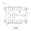
- FIGS. 2 a - dare perspective, front, side and top views of a robot having flippers.
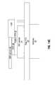
- FIGS. 3 a - pare side views of a sequence of stair surmounting maneuvers.
- FIG. 4is flowchart of an obstacle surmounting control routine.
- FIGS. 5 a - rare side views of another sequence of stair surmounting maneuvers
- FIG. 6is flowchart of another obstacle surmounting control routine.
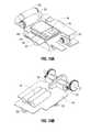
- FIG. 7is a perspective view of a robot in an elevated position during a self-righting maneuver.
- FIG. 8is a perspective view of a robot in a partially elevated position.
- FIG. 9is a partially exploded view of a robot chassis.
- FIG. 10is a perspective view of a flipper drive system.
- FIG. 11is a perspective view of opposing sprockets of a slip clutch.
- FIG. 12is a cross-sectional view of the opposing sprockets of the slip clutch assembled on a drive axle.
- FIG. 13is a perspective view of a robot including sensor zones
- FIGS. 14 a - care perspective and like views of an electrical subassembly of a robot.
- FIG. 15is a functional block diagram of system components of a robot.
- a mobile robotic vehicle or robot 2is operable via an Operator Control Unit (OCU) or remote control system 4 .
- Remote communicationscan be transmitted via radio signal, infra red signal, wi-fi signal, cellular signal, or other suitable signal.
- robot 2can perform automated routines without remote use intervention.
- a combination of automated routines and user controlsare used to maneuver robot 2 .
- Remote control system 4can include any number of radio transceivers or other communications links and can interface with any number of robots or though any number of robots as mesh network nodes or other parts of a communications network.
- This version of robot 2is sized to be portable, and to substantially fit within a bounding volume approximately 18 cm (7 in.) long, 12 cm (5 inches) wide and 6 cm (2 inches) tall.
- the overall dimensions of a particular embodimentare about 16 cm ⁇ 12 cm ⁇ 6 cm excluding the antenna and camera protruding from the chassis, with a total mass of about 0.5 kg and a top speed of about 0.6 m/s over a smooth surface.
- the vehicleis configured to fit in a combat uniform cargo pants pocket.
- Multiple robots 2can be stacked to fit in a backpack. Compactness and portability allow robot 2 to be easily transported by an individual and to be deployed into an area by simply tossing the robot.
- the robotis removed from a carrying compartment, is activated by pulling a grenade-style pull pin, and is then tossed down a corridor, up a stairwell or into a window.
- the platformcan be thrown by a single person or launched into an upper window or rooftop using an improvised slingshot. Landing on a top floor, the remotely operated platform may be able to bypass some typical obstacles and travel down stairs. The operator can evaluate the resultant video before determining the next course of action.
- the robotcan also be used to search for and assess booby traps, enemy personnel, and improvised explosive devices (IEDs).
- the robotis between 0.5 and 1.0 Kg and the remote control 4 is a small PDA with a mass less than 0.5 kg.
- a separate charging stationcan be used for both the remote control 4 and robot 2 .
- Remote control system 4allows an operator to control robot 2 from a distance.
- the operatorcan select different levels of human control over the robot, ranging from a teleoperation mode, in which the operator directly controls the motors and actuators on the robot, to autonomous operation, in which the operator passes higher-level command to the robot.
- robot 2can perform tasks such as following a wall, avoiding an obstacle, surmounting an obstacle, avoiding a drop off or “cliff,” avoiding becoming high centered, evading a moving object, positioning a transceiver, self-righting, repositioning to optimize communication network coverage, and the like.
- Alternative versions of the remote control system 4support teleoperation as well as a means of switching between teleoperation and autonomous control.
- the usercan interrupt autonomous operation of the robot at any time to give commands and direction, and the robot can operate autonomously when not receiving particular directions from the user.
- the systemprovides predetermined warning signals to the operator, for instance if it is unable to operate autonomously, possibly by means of a vibrating unit that could be worn by the operator and which would be effective in a noisy environment.
- the usercan add additional tasks to the robot's mission and request notification from the robot when milestone tasks have been achieved.
- Versions of the robotcan perform various autonomous tasks which can be initiated by the operator from remote control system 4 . These include obstacle avoidance, wall following, climbing stairs, recovery from high centering, self-righting, returning “home,” searching for a designated object, mapping, and establishing a communications network.
- the robotcan use the various mobility modes described above in these autonomous operations, and if necessary, can call for operator assistance during its execution of a task.
- Alternative configurations of pivotal armscan be used. For example, a single central “arm” can be used.
- robot 2includes a body portion or chassis 6 housing, inter alia, drive components, a power supply, control system and communication module.
- a pair of drive wheels 8is positioned at a forward end of chassis 6 and a pair of idler wheels 10 is positioned at a rearward end of chassis 6 .
- Wheels 8 and 10can include spiral spokes to provide additional impact resistance.
- a pair of resilient tracks 12is trained about wheels 8 and 10 on opposing sides of chassis 6 extending from the sides of the chassis to provide a driven support surface for robot 2 .
- Tracks 12are continuous flexible belts with interior surface features for engaging drive wheels 8 and exterior surface features for gaining traction over various terrains.
- First and second rotatable arms or flippers 14extend radially from a common drive axle 16 .
- idle wheels 10free spin about flipper drive axle 16 .
- Flippers 14are configured to extend through a 360 degree range of motion to allow robot 2 to perform various positioning, obstacle surmounting and self-righting maneuvers. In other embodiments, a single rotatable arm can accomplish these functions.
- flippers 14are made from a flame rated advanced formula polymer with 85D Shore hardness available from Quantum Cast, part number AFP3100FR, UL 94 FR and FAR 25.853.
- flippers 14for attachment of flipper accessories, e.g., cameras, sensors, or wheels positioned at the flipper tip or along the flipper length.
- flipper accessoriese.g., cameras, sensors, or wheels positioned at the flipper tip or along the flipper length.
- a camera, antenna or sensorcan be mounted on the end of the arm to provide better exposure or higher vantage point.
- Robot 2can be rotated to any desired angle relative to chassis 6 .
- Robot 2is designed to move about in a variety of environments, including an urban environment of buildings (including staircases), streets, underground tunnels, as well as in vegetation, such as through grass and around trees.
- Robot 2has a variety of features which provide robust operation in these environments, including impact resistance and tolerance of debris entrainment.
- Wheels 8 and 10are positioned on chassis 6 to provide greater ground clearance when right side up, yet can provide sufficient clearance in some embodiments for operation when robot 2 is inverted. In the present embodiments, robot 2 preferably recovers from a tumble or fall in which it is inverted by a self-righting function.
- Chassis 6 and other rigid robot componentsare designed for strength and low weight and are made from durable plastic, polymer, composites, 7075-T6 aluminum or other suitable lightweight, impact resistant materials.
- Tracks 12 , wheels 8 and 10 and flippers 14are also configured to be impact resistant.
- wheels 8 and 10can be a pliable material and can include spiraled spokes to provide a degree of resilience. Impact resistance is accomplished, in part, by surrounding much of the vehicle with compliant tracks 12 with pliable cleats. Tracks 12 and cleats provide a first layer of impact protection.
- Tracks 12are configured to provide skid steering and include compliant belts made of polyurethane or a similar flexible material.
- the beltsare abrasion resistant and have high strength and minimal stretch due to internal steel or fiber cording.
- Tracks 12define a left-right alternating tread to smooth successive impacts on most surfaces with a spacing between successive edges on the sides to catch larger terrain features for traction. Without a bogey rail, the robot tends to tread on the portion of the tracks at wheels' bottom dead center.
- Tracks 12can be stretched over wheels 8 and 10 and driven primarily by friction.
- the surfaces of wheels 8 and 10 contacting tracks 12can be provided with a fine knurl pattern to enhance friction with tracks 12 and prevent slippage from formation of water films between wheels 8 and 10 and tracks 12 .
- tacks 12 and drive wheels 8can be formed with complementary features to provide positive drive engagement.
- wheels 8 and 10can have V-shaped grooves around their circumference to receive an integral V-shaped rib on the inside of track 12 .
- Tracks 12can include cleats, ridges, or other projections for additional traction. Such cleats can be angled to divert debris away from chassis 6 .
- Flippers 14can be can be continuously rotated around axle 16 . Flippers 14 can be rotated to a forward “stowed” position next to chassis 6 . Alternatively, flippers 14 can be rotated to a rearward trailing position to prevent catching of the ends of flippers 14 on terrain, for example in tall grass. In some embodiments, to prevent possible damage, flippers 14 can automatically return to a stowed position when robot 2 detects that it is in free fall.
- flippers 14are further configured to be driven to rotate at predetermined intervals in stair or obstacle surmounting maneuvers. Flipper positioning angles are stated with reference to the horizontal axis of chassis 6 as shown in FIG. 4 with 0 degrees being the stowed flipper position, 90 degrees being a vertical position, 180 being a trailing position and 270 being a downward position.
- An obstacle surmounting control routineis initiated by detection of an obstacle or predetermined scenario or by operator input. In state 1 of the routine, shown in FIG. 3A , robot 2 approaches a stair with flippers 14 is a forward stowed position substantially parallel to the ground at 0 degrees.
- a main obstacle surmounting control routine 100is run on a controller at 64 Hz while sampling accelerometer data at 16 Hz and updating the flipper position at 16 Hz.
- the control routineUpon detection of the stair or other obstacle, the control routine enters state 2 , in which flippers 14 are rotated upward and rearward between approximately 45 and 90 degrees, as shown if FIG. 3B .
- state 3 shown in FIG. 3Cthe forward end of robot 2 begins to ascend the front face or riser of a stair.
- the routineOnce the robot has ascended to a predetermined position shown in FIG. 3C as detected by an accelerometer, e.g., between about 15 and 45 degrees or a sensor reading of about 0.75 g, the routine enters state 4 . Passage of a predetermined time since entering state 3 , e.g., 3 seconds, can also trigger the fourth state.
- flippers 14are rotated further counterclockwise or rearward between the positions shown in FIGS. 3D-3G , e.g., between about 90-125 degrees, as tracks 12 are further driven such that the forward end continues to ascends the stair riser and rearward end of robot 2 approaches the stair riser.
- flippers 14contact the underlying surface at approximately 125 degrees and the routine enters a fifth state.
- flippers 14are rotated quickly counterclockwise to lift the rearward end of robot 2 through the range shown in FIGS. 3G-M , e.g., between about 125 and 275 degrees, while tracks 12 are driven until the center of gravity of robot 2 clears the nose of the stair as shown in FIG. 3N .
- Flippers 14further serve to resist back sliding or any wheelie tendency as robot 2 clears the stair nose.
- flippers 14are kicked backward from about 275 degrees, e.g., to less than about 235 degrees, in an effort to topple robot 2 forward from a possible teetering position.
- the routineenters a seventh state.
- robot 2overcomes the stair and tips forward as the center of gravity clears the stair nose as shown in FIG. 3M .
- flippers 14are rotated clockwise towards a trailing position as shown in FIG. 3O . This prevents flippers 4 from catching on the surmounted obstacle as the robot is driven forward.
- an eighth routine statecauses flippers 14 to return to a default position, e.g., substantially vertical, to prepare to surmount a second stair.
- Flipper positionis determined in the different states using a flipper position sensor.
- FIGS. 5A-R and FIG. 6Another obstacle surmounting routine 200 is described with reference to FIGS. 5A-R and FIG. 6 .
- flippers 14are used to initially raise the forward end of the robot 2 . This can also be particularly helpful if a stair riser is angled outward.
- state 1the robot advances forward towards the stair riser as shown in FIG. 5A .
- Tracks 12are driven forward until the robot reaches the riser.
- flippers 14are rotated to the stowed position, e.g., 0 degrees in preparation for lifting the nose of the robot.
- flippers 14are rotated “clockwise” downward such that the distal ends of flippers 14 contact the underlying surface forward of the center of gravity of robot 2 as shown in FIG. 5B .
- Tracks 12are advanced to ascend the stair riser.
- the predetermined angleis selected to approximate the angle at which the frictional forces between the tracks and the floor and the tracks and the stair riser are sufficiently balanced to prevent back-sliding of the robot.
- Balance of the frictional forces between the track the riser and underlying surfaceenables the track to ascend the riser without continued clockwise rotation of flippers 14 .
- the routinecan periodically test to see if the friction balance point has been achieved by slightly lifting the flippers and using the accelerometers to detect backsliding. Once it is determined that the balance point has been reached or passed, the flipper is no longer needed to raise the forward end of the robot. If the accelerometer detects slippage or backsliding of the robot, previous states can be repeated as needed.
- the track velocityis coordinated with the flipper motions to help maintain traction and frictional balance.
- flippers 14are rotated clockwise to an “upwards” position as shown in FIGS. 5E-F , e.g., to 90 degrees, to prevent the robot from flipping over backwards as the wheels continue to climb.
- This movementis preferably performed without substantially shifting the center of gravity or introducing disturbances that would upset the frictional balance.
- flippers 14It is advantageous for flippers 14 to be long enough to extend forward of the center of gravity, yet short enough to not get caught under a stair nose when later rotating counterclockwise, as shown in FIGS. 5D-E to prepare to raise the rearward end of the robot.
- An estimated maximum flipper lengthis calculated by adding the wheel radius to the product of the length of the robot chassis and cosine of the angle at which the frictional forces are sufficiently balanced to enable continued climbing by the tracks. This flipper length provides sufficient clearance for retraction of the flippers from a forward to a rearward position after partial ascend of a stair rise by the robot.
- flipper lengthcan be dictated by anticipated obstacle profiles including more aggressive forward riser angles.
- tracks 12are advanced to position the chassis substantially vertically against the stair riser with flippers rotated counterclockwise to a point adjacent to or contacting the ground as shown in FIGS. 5G-J .
- flippers 14are extended, e.g., from about 100 degrees to 175 degrees, while tracks 12 are driven at a “matched” velocity as shown in FIGS. 5J-O , or slightly faster as dictated by the geometry of the problem, to allow the track to evenly surmount the stair nose as the robot is pushed upward by flippers 14 .
- Matching of the track velocity to the flipper rotationmeans that the tracks are advancing a distance equal to the amount of extension provided by rotation of flippers 14 .
- Velocity matchingcan also be used to maintain an angle of incline of chassis 6 as the robot surmounts the stair nose.
- tracks 12are driven while flippers 14 simply drag behind to prevent backsliding or wheelies as shown in FIG. 5N .
- Flippers 14are paused momentarily at the point of maximum extension, e.g., when the flipper tip is farthest away from the track/step corner, while the tracks continue to be driven forward.
- the track speedcan be varied to achieve a desire bouncing pattern.
- flippers 14are again rotated counterclockwise to provide an extra extension to slightly level out the robot. This “over extension” of the flippers can also help tip the robot center of gravity over the stair nose.
- tracks 12are driven quickly while flippers 14 are slowly rotated clockwise back to the full extension point to climb onto the top of the step as shown in FIGS. 5P-R .
- the flipperscan catch the robot should it happen to back slide or tumble backwards. Once the center of mass of the robot extends forward of the stair nose, the robot falls forward on top of the step.
- flippers 14are restored to a default driving or stowed position.
- flippers 14can be continuously rotated to overcome a high centered position.
- a high centered positioncan be detected in multiple ways. For example, monitoring of video data, monitoring accelerometer data, comparing odometer and navigational data, GPS data discrepancies.
- Track motionscan be coordinated with flipper motions to pull the vehicle forward, e.g., by driving the tracks when the flipper is in contact with the surface at the same rate that the flipper is expected to pull the vehicle forward.
- Flipper rotation ratescan depend on the expected or detected terrain, e.g., whether the flipper tips will penetrate the terrain surface.
- the effective flipper radiuscan be dynamically determined by signal processing the accelerometer signals after repeated rotations of the flipper as a function of flipper tip penetration into the underlying surface.
- the trackscan be driven when the flippers are in contact with the underlying surface.
- the flipper rotational ratecan be selected as a function of surface penetration and movement of the robot over the terrain and baseline data for behavior of the robot driving over different terrains.
- the flippersextended substantially the distance between the drive wheel axle and the idler wheel axle.
- the flipper lengthis selected to fit entirely within the length of the chassis and to extend forward of the robot center of gravity. In some cases the flippers are at least as long as the idler wheel radius. The flippers or flipper length can be selected based on the dimensions of anticipated obstacles.
- flippers 14are configured to extend from axle 16 centrally to a point beyond the center of gravity of robot 2 . This allows robot 2 to be inverted or self-righted simply by rotation of flipper 14 through an arc of 90 degree beyond contact with an underlying surface.
- Robot 2can descend stairs forwards or backwards with flippers 14 in a stowed position, driving tracks 12 either direction and tumbling or rolling to a resting position.
- robot 2has more ground clearance in one orientation than another.
- a camera, antenna, sensor or robot accessorymay need to be reoriented upward if robot 2 lands upside down after a descent from an obstacle.
- flippers 14can also be rotated to partially elevate the rearward end of robot 2 .
- flippers 14can be used to raise or upend robot 2 to position a camera, antenna, sensor, munitions or the like at a desired height or angle or for helping to pull robot 2 from a high centered position.
- Flippers 14can be repeatedly or continuously rotated in either direction to provide a “swimming” motion to help propel robot 2 through loose debris, gravel, sand and the like. Flippers 14 can raise the nose of the vehicle, to both help start a climb and to elevate a fixed camera.
- robot chassis 6houses, inter alia, wheel drive motors 20 and 22 for powering drive wheels 8 and a flapper drive motor 24 .
- Chassis 6also houses an electrical subassembly 26 and battery (not shown) positioned below electrical subassembly.
- the batteryis a significant portion of the total weight of robot 2 and is positioned substantially centrally front to back and towards the bottom of chassis 6 .
- a clamshell chassis body designallows provides sufficient volume for electronics and mechanical drive mechanisms within a protective cover.
- Flipper drive motor 24is used to control the angle between flappers 14 and chassis 6 .
- Flipper drive motor 24is coupled via a gear reduction train to axle 16 .
- a slip clutchcan be used to transfer output torque from flipper drive motor 24 to axle 16 .
- a slip clutchcan be adjustable to set a predetermined slip torque.
- Flippers 14are connected via solid axle 16 and an optic sensor on axle 16 provides for detection of the position of flippers 14 regardless of clutch slippage.
- One clutch embodimentincludes two beveled gears engaged with a spring, similar to a cordless drill clutch.
- Axle 16passes through a central opening in idler wheels 10 and fixedly connects to flippers 14 .
- flippers 14At the rear of the robot are two flippers 14 with the ability to rotate 360° continuously to flip the robot over when inverted.
- the flippersalso assist the robot in climbing and negotiating small obstacles.
- a slip clutchAlso integrated into the flipper mechanism is a slip clutch to protect the gearing in case of impact.
- Drive motors 20 , and 22are 1 watt DC brushed motors. In other versions of the robot, brushless motors can be used. Drive motors 20 and 22 turn output drive gears that attach to the wheels via integral splines. Output drive gears are retained via brass or Delrin bushings that register and align complementary portions of the chassis body. Drive motors 20 and 24 are geared down 29:1 to drive wheels 8 .
- Steeringis accomplished using differential speed of the tracks 14 on either side of the robot by varying the speed of drive motors 20 and 22 .
- the robotwill, in principle, skid around the center of chassis 6 approximately at the midpoint of the length of tracks allowing complete turning with the extremes of the robot staying within a 23 cm (9′′) diameter circle.
- tracks 14can be driven while flippers 14 maintain an end of robot 2 elevated above an underlying surface, for example to reposition an elevated antenna or camera.
- Other preprogrammed flipper or robot positionscan include fully extended, stowed, inclined, upright, and “wheelie.”
- robot 2can perform several maneuvers including self righting, stair climbing, and recovery from high centering.
- the chassis bodycan further serve to retain bushings for moving parts and as a mounting surface for an antenna, camera, microphone, sensors and the like. Dust and moisture seals can be provided where axles or other components pass through the chassis body.
- bushingsecuring at openings around chassis body 6serve to support axle 16 and the idler wheel axles.
- Chassis body 6can also carry an antenna connector base (e.g., standard SMA antenna connector).
- flippers 14are rotated by drive motor 24 (0.4 watt DC brushed motor) via gear train 26 .
- Flipper drive motor 24is geared down 298:1 to axle 16 to provide a torque of approximately 400 mNm ( ⁇ 2 ⁇ required to lift vehicle weight).
- Clutchcan be adjusted to provide up to 700 mNm of slip torque.
- a slip clutchprevents overloading of flipper drive motor 24 and gearing, for example due to an impact on the arms.
- Flippers 14can be stowed parallel to chassis 6 and tracks 12 when it is deployed by tossing or dropping it through a window or door or when the robot tumbles.
- a mechanical energy storageprovides for sudden release to move the flippers to allow the robot to perform a small leap motion.
- An example energy storage systemcan be a spring, flywheel or other mechanical energy storage mechanism.
- a slip clutch 70is provided on axle 16 between drive motor 24 and flippers 14 .
- Slip clutch 70includes a first sprocket 72 carrying a series of drive teeth 74 on a first rotary surface 76 .
- First sprocket 72is fixedly attached to axle 16 .
- a second sprocket 78defines a series of slots 80 in a second rotary surface 82 for receiving the drive teeth 74 of first sprocket 72 .
- Drive teeth 74 and slots 80remain engaged so long as first and second rotary surfaces 76 and 82 remain substantially in contact.
- Second sprocket 78includes gear teeth about its circumference to engage drive motor 24 .
- drive motor 24turns second sprocket 78 which in turn rotates first sprocket 72 and axle 16 to rotate flippers 14 .
- a slip clutchcan be formed of sufficiently pliable material to allow flexure of rotary surfaces 76 and 82 under sufficient torque. Any number of frictional or cammed surfaces or other known types of slip clutches can be substituted for slip clutch 70 .
- robot 2is provided with a pair of end sensors 28 and side sensors 30 .
- Sensors 28can be positioned on one or both ends of robot 2 and sensors 30 can be positioned on one or more sides of robot 2 .
- Sensors 28 and 30include IR emitter/detector pairs. Sensors 28 are directed substantially parallel in front of tracks 12 to act as cliff detectors to detect and avoid falls and sensors 30 are directed outward from chassis 6 to act as wall detectors. Sensors 28 and 30 can include filtering features to accommodate ambient sunlight. Sensors 28 and 30 provide feedback that is used by robot 2 , for example, to follow a wall or avoid a drop off.
- Sensors 28 and 30can include sonar, infra red, proximity, impact or other sensor suitable to detect the presence or absence of an object in the sensor range. Additional sensor based autonomous robot behavior routines are disclosed in U.S. Pat. No. 6,883,201, titled “ROBOT OBSTACLE DETECTION SYSTEM” which is incorporated herein by reference in its entirety.
- Additional autonomous behavior routines and control systemsare disclosed in U.S. Pat. No. 6,809,490 titled “METHOD AND SYSTEM FOR MULTI-MODE COVERAGE FOR AN AUTONOMOUS ROBOT” and U.S. Pat. No. 7,459,871 titled “DEBRIS SENSOR FOR CLEANING APPARATUS,” which are incorporated herein by reference in their entirety.
- the routinesinclude motion control and coverage behaviors such as spiral coverage, cruising, bounce and recoil from an obstacle, wall following, self-alignment, and escape behaviors as selected by an arbiter according to principles of behavior based robotics.
- Additional reactive controls and behavior routinesare provided for reacting to and concentrating on a point of interest in the coverage space. Similar behaviors can be used to seek out a peak signal strength peak or radio hot spots or to reposition a robot as a node in a mesh network.
- Sensorscan be shielded within the track volume, within the protective shell of chassis 6 or positioned on the front and rearward ends of the vehicle.
- the top and bottom portions of chassis 6can be fitted with any number of sensors, cameras, antennae, chemical sensors, bio-sensors, radiation sensors and the like.
- robot 2can be powered off if sensors detect that drive motors 20 or 22 have stalled of if the robot is otherwise stuck.
- Chassis 6also supports a camera 32 and antenna 34 to provide video telemetry and other communications data.
- Camera 32is depicted positioned slightly rear of center, with the lens angled up to minimize the field of view obstructed by the robot vehicle itself.
- Flippers 14can be rotated to raise the nose of the vehicle further if the camera view is insufficiently high. To look over an edge, flippers 14 can be used to raise the rear of the vehicle to depress the camera view angle.
- Transmission of video telemetry data or other sensor data from within a buildingcan enable a small force to quickly and safely assess a location or situation.
- a cameracan be used to quickly and safely determine the presence and location of an adversary or explosive in a building
- Robot 2includes the capability of carrying a variety of accessories or sensors, including cameras, sonar sensors, infra-red detectors, inertial sensors, motor position, velocity and torque sensors, inclinometers, a magnetic compass, microphones, sound generator, or small weapon. Sensors can be placed on all surfaces of the robot. For example, night time or low light operation can be performed using onboard light such as an infra-red (IR) array with a useful range of several meters. A small white light can also be provided for up close color identification of objects.
- IRinfra-red
- a multi camera arraycan provide stereoscopic vision for navigation and video transmission back to remote control system 4 .
- multiple cell phone style cameraseach with multi-megapixel accuracy and a 90° field of view, to provide full 360° field of view.
- the robotcan be configured to monitor for motion and alert the operator if motion is detected.
- an onboard microphonecan enable an alert to be sent to the operator if sound above a designated threshold is detected.
- Onboard computing coupled with a multi megapixel imagercan provide high resolution image capture and digital pan tilt zoom of the digitally compressed and encrypted video stream. This minimizes the mechanical complexity of the system by eliminating the need for a mechanical pan-tilt assembly, and allows the use of image processing for unattended operation such as change detection and digital video recording of motion.
- Integrated infrared illuminatorscan provide sufficient illumination for navigation in an urban environment, while white light illuminators can be used to identify targets up close.
- white light illuminatorscan be used to identify targets up close.
- One exampleis a 1.3 Megapixel camera with mpeg4 compression capabilities.
- electrical subassembly 26is mounted between the flipper drive motor 24 and wheel drive motors 20 , 22 above batteries 52 .
- Electrical subassemblyincludes a main printed circuit board (PCB) 40 to which are electrically connected a removable mass memory 44 , USB communication module 46 ; SDIO communication module 48 , SDIO port 50 .
- the battery, drive motors 20 , 22 and 24 , camera 32 and antenna 34are operably coupled to electrical subassembly 26 .
- PCB 40also carries end sensors 28 and side sensors 30 .
- PCB 40can include rigid circuit boards, flexible polyimide circuits, or other circuit modules or combinations thereof, and may provide power regulation, motion control, sensors, and other functions.
- Battery 52includes a lithium ion battery pack with three 18650 cells in series. Each cell has a capacity of 2.6 AHr, and contains 0.78 grams/cell of lithium, or 2.3 g of lithium per assembled robot.
- Internal rechargeable Li-Ion battery pack 52has a two hour charge time via 110v or 220v circuits. Both robot 2 and the OCU remote control 4 can be charged by a single adapter capable of accepting universal power (100-240 VAC 50/60 Hz). Optional charge adapters can be used for charging at 12-24 VDC. Battery 52 can be attached directly to PCB 40 via VHB tape. Solar power can be used to charge the battery or provide for extended duration low power surveillance.
- a substantial capacitor bankis used to minimize the ripple in the battery draw in powering the drive motors. It may be desirable in some cases to destroy internal circuits by reversing the polarity of the capacitor bank into the lithium batteries to ignite the batteries. A sudden reversal of the energy from the capacitors creates a large current surge sufficient to cause an electrical fire. This would help frustrate the ability of hostile warfighters from re-using any of the components.
- PCB 40includes one or more computer processors and associated memory systems.
- PCB 40is coupled to communication modules 46 , 48 , which include, for example, a radio for exchanging control and feedback information with remote control system 4 .
- Communications range with USB and SDIO radioswas experimentally found to be approximately 40 meters of open area or through two cinderblock walls of a building.
- Odometry sensorsdetect a pattern referenced to axle 16 , such as a slotted or patterned strip secured to an axle, e.g., via a piece of clear heatshrink tubing, or a slotted disc attached to an axle or driven wheel 8 .
- the odometery sensoris located on the idler wheel to account for track slippage on drive wheel 8 . Odometry reading accuracy may be increased by harder turns as opposed to sweeping turns.
- Additional sensorsdetermine the angle between flippers 14 and chassis 6 and the rate of rotation of flippers 14 or wheels 8 or 10 .
- An angular rate sensoris placed near the center of gravity of the robot 2 to track the bearing of the robot and provide increased positioning accuracy, facilitating movement in areas with few visual landmarks.
- Optional accelerometerscan be located near the angular rate sensor. These inputs are used during full or partial autonomous robot operation.
- PCB 40is electrically connected to an iMX31 processor 54 , USB communication module 46 , SDIO communication module 48 , flash memory 44 , infrared sensors 28 , proximity sensors 30 , STmicro LIS344ALH three axis accelerometer 56 , flipper rotary position sensor (RPS) 58 , SDIO/USB Payload PCB 42 , and STmicro LISY300AL angular right sensor, camera 32 , battery 52 , drive motors 20 , 22 and 24 with appropriate interfaces, controllers and the like.
- the electrical componentsmay also include one or more of the following: microphone, yaw sensor, active/passive analog IR LED and phototransistors, SDIO radios, 802.11b/g/n radio, satellite phone, EVDO cellular phone, USB peripherals, additional batteries, Bluetechnix IMX, GPS transponders and the like.
- communications modules 46 and 48serve to provide multi-hop style communications chains, to extend the usefulness of the robots deep into radio frequency (RF) denied areas using standard Optimized Link State Routing daemon (OLSRd) software mesh networking.
- RFradio frequency
- OLSRdOptimized Link State Routing daemon
- the robotscan be repositioned to maintain a self healing communications network
- the deactivation plugis removed to activate each robot.
- the robotsare then placed in approximate locations for autonomous mesh networking.
- the robotsautomatically reposition to maintain the mesh network.
- the robotscan be recovered as required and charged to be ready for the next mission.
- the deactivation plugsare installed into the charge connectors to power off the robots and keep the batteries from draining prior to the next mission.
Landscapes
- Engineering & Computer Science (AREA)
- Chemical & Material Sciences (AREA)
- Combustion & Propulsion (AREA)
- Transportation (AREA)
- Mechanical Engineering (AREA)
- Manipulator (AREA)
- Control Of Position, Course, Altitude, Or Attitude Of Moving Bodies (AREA)
Abstract
Description
Claims (20)
Priority Applications (4)
| Application Number | Priority Date | Filing Date | Title |
|---|---|---|---|
| US13/721,918US8573335B2 (en) | 2008-12-09 | 2012-12-20 | Mobile robotic vehicle |
| US14/036,902US9180920B2 (en) | 2008-12-09 | 2013-09-25 | Mobile robotic vehicle |
| US14/861,263US20160176453A1 (en) | 2008-12-09 | 2015-09-22 | Mobile robotic vehicle |
| US16/865,536US11565759B2 (en) | 2008-12-09 | 2020-05-04 | Mobile robotic vehicle |
Applications Claiming Priority (4)
| Application Number | Priority Date | Filing Date | Title |
|---|---|---|---|
| US12/331,380US7926598B2 (en) | 2008-12-09 | 2008-12-09 | Mobile robotic vehicle |
| US13/078,618US8074752B2 (en) | 2008-12-09 | 2011-04-01 | Mobile robotic vehicle |
| US13/323,019US8353373B2 (en) | 2008-12-09 | 2011-12-12 | Mobile robotic vehicle |
| US13/721,918US8573335B2 (en) | 2008-12-09 | 2012-12-20 | Mobile robotic vehicle |
Related Parent Applications (1)
| Application Number | Title | Priority Date | Filing Date |
|---|---|---|---|
| US13/323,019ContinuationUS8353373B2 (en) | 2008-12-09 | 2011-12-12 | Mobile robotic vehicle |
Related Child Applications (1)
| Application Number | Title | Priority Date | Filing Date |
|---|---|---|---|
| US14/036,902ContinuationUS9180920B2 (en) | 2008-12-09 | 2013-09-25 | Mobile robotic vehicle |
Publications (2)
| Publication Number | Publication Date |
|---|---|
| US20130256042A1 US20130256042A1 (en) | 2013-10-03 |
| US8573335B2true US8573335B2 (en) | 2013-11-05 |
Family
ID=42229833
Family Applications (9)
| Application Number | Title | Priority Date | Filing Date |
|---|---|---|---|
| US12/331,380ActiveUS7926598B2 (en) | 2008-12-09 | 2008-12-09 | Mobile robotic vehicle |
| US13/052,022ActiveUS8122982B2 (en) | 2008-12-09 | 2011-03-18 | Mobile robot systems and methods |
| US13/078,618ActiveUS8074752B2 (en) | 2008-12-09 | 2011-04-01 | Mobile robotic vehicle |
| US13/323,019ActiveUS8353373B2 (en) | 2008-12-09 | 2011-12-12 | Mobile robotic vehicle |
| US13/351,382Active2028-12-28US8616308B2 (en) | 2008-12-09 | 2012-01-17 | Mobile robot systems and methods |
| US13/721,918ActiveUS8573335B2 (en) | 2008-12-09 | 2012-12-20 | Mobile robotic vehicle |
| US14/036,902ActiveUS9180920B2 (en) | 2008-12-09 | 2013-09-25 | Mobile robotic vehicle |
| US14/861,263AbandonedUS20160176453A1 (en) | 2008-12-09 | 2015-09-22 | Mobile robotic vehicle |
| US16/865,536Active2029-07-01US11565759B2 (en) | 2008-12-09 | 2020-05-04 | Mobile robotic vehicle |
Family Applications Before (5)
| Application Number | Title | Priority Date | Filing Date |
|---|---|---|---|
| US12/331,380ActiveUS7926598B2 (en) | 2008-12-09 | 2008-12-09 | Mobile robotic vehicle |
| US13/052,022ActiveUS8122982B2 (en) | 2008-12-09 | 2011-03-18 | Mobile robot systems and methods |
| US13/078,618ActiveUS8074752B2 (en) | 2008-12-09 | 2011-04-01 | Mobile robotic vehicle |
| US13/323,019ActiveUS8353373B2 (en) | 2008-12-09 | 2011-12-12 | Mobile robotic vehicle |
| US13/351,382Active2028-12-28US8616308B2 (en) | 2008-12-09 | 2012-01-17 | Mobile robot systems and methods |
Family Applications After (3)
| Application Number | Title | Priority Date | Filing Date |
|---|---|---|---|
| US14/036,902ActiveUS9180920B2 (en) | 2008-12-09 | 2013-09-25 | Mobile robotic vehicle |
| US14/861,263AbandonedUS20160176453A1 (en) | 2008-12-09 | 2015-09-22 | Mobile robotic vehicle |
| US16/865,536Active2029-07-01US11565759B2 (en) | 2008-12-09 | 2020-05-04 | Mobile robotic vehicle |
Country Status (1)
| Country | Link |
|---|---|
| US (9) | US7926598B2 (en) |
Cited By (10)
| Publication number | Priority date | Publication date | Assignee | Title |
|---|---|---|---|---|
| US20120200149A1 (en)* | 2011-01-27 | 2012-08-09 | Irobot Corporation | Resilient wheel assemblies |
| US20160176453A1 (en)* | 2008-12-09 | 2016-06-23 | Irobot Corporation | Mobile robotic vehicle |
| US9868421B2 (en) | 2015-06-17 | 2018-01-16 | Ample, Inc. | Robot assisted modular battery interchanging system |
| US10414039B2 (en) | 2016-09-20 | 2019-09-17 | Foster-Miller, Inc. | Remotely controlled packable robot |
| US10471589B2 (en) | 2016-09-20 | 2019-11-12 | Foster-Miller, Inc. | Remotely controlled packable robot |
| US10611418B2 (en) | 2011-01-27 | 2020-04-07 | Flir Detection, Inc. | Small unmanned ground vehicle |
| US10889340B2 (en) | 2017-07-07 | 2021-01-12 | Foster-Miller, Inc. | Remotely controlled packable robot with folding tracks |
| US11331818B2 (en) | 2018-10-11 | 2022-05-17 | Foster-Miller, Inc. | Remotely controlled packable robot |
| US12296710B2 (en) | 2023-05-16 | 2025-05-13 | Ample, Inc. | Battery-exchange service station |
| US12421088B2 (en) | 2023-05-16 | 2025-09-23 | Ample, Inc. | Configurable vehicle lift and service station |
Families Citing this family (163)
| Publication number | Priority date | Publication date | Assignee | Title |
|---|---|---|---|---|
| AU2001253151A1 (en)* | 2000-04-04 | 2001-10-15 | Irobot Corporation | Wheeled platforms |
| US8930023B2 (en) | 2009-11-06 | 2015-01-06 | Irobot Corporation | Localization by learning of wave-signal distributions |
| US9094082B1 (en)* | 2012-03-29 | 2015-07-28 | The United States Of America As Represented By The Secretary Of The Navy | System and method for remotely-operated deployment and retrieval of communication relays |
| KR100857540B1 (en)* | 2007-09-27 | 2008-09-08 | (주)컨벡스 | Mobile robot |
| ES2543226T3 (en)* | 2008-11-03 | 2015-08-17 | Redzone Robotics, Inc. | Pipe inspection device and method to use it |
| WO2010099416A1 (en)* | 2009-02-27 | 2010-09-02 | Magna Electronics | Alert system for vehicle |
| US20110054690A1 (en)* | 2009-08-25 | 2011-03-03 | Ehud Gal | Electro-mechanism for extending the capabilities of bilateral robotic platforms and a method for performing the same |
| KR101055567B1 (en)* | 2009-09-18 | 2011-08-08 | 성균관대학교산학협력단 | Intelligent User Interface Device and Control Method for Service Robot |
| JP6162955B2 (en)* | 2009-11-06 | 2017-07-12 | アイロボット コーポレイション | Method and system for completely covering a surface with an autonomous robot |
| JP5432688B2 (en)* | 2009-12-03 | 2014-03-05 | 株式会社日立製作所 | Mobile robot and its running stabilization method |
| US8532823B2 (en)* | 2010-02-12 | 2013-09-10 | American Science And Engineering, Inc. | Disruptor guidance system and methods based on scatter imaging |
| DE102010018756A1 (en)* | 2010-04-29 | 2011-11-03 | Deutsches Zentrum für Luft- und Raumfahrt e.V. | Exploration device for use in e.g. country vehicle for exploring e.g. earth, has arms are rotated around specific degree for variably controlling travel type of device and motion sequence of arms and laterally attached at housing |
| FR2961315B1 (en)* | 2010-06-11 | 2013-10-11 | Roboplanet | ROBOTIC ESCALADOR LOAD CARRIER |
| EP2585651B1 (en)* | 2010-06-28 | 2014-08-13 | Zodiac Pool Care Europe | Automatic pool cleaners and components thereof |
| DE202010017594U1 (en) | 2010-10-07 | 2012-03-22 | Technische Universität Ilmenau | Forced-coupled mechanism for generating a steady transport movement |
| EP2482024B1 (en) | 2011-01-27 | 2015-10-07 | iRobot Corporation | Small unmanned ground vehicle |
| CA2863971C (en)* | 2011-02-07 | 2018-10-09 | Mobility 2000 (Australia) Limited | Step-climbing attachment for a wheeled chair |
| US8963159B2 (en) | 2011-04-04 | 2015-02-24 | Qualcomm Mems Technologies, Inc. | Pixel via and methods of forming the same |
| US9134527B2 (en) | 2011-04-04 | 2015-09-15 | Qualcomm Mems Technologies, Inc. | Pixel via and methods of forming the same |
| USD677344S1 (en)* | 2011-04-25 | 2013-03-05 | Brookstone Purchasing, Inc. | Remotely controlled toy tank vehicle |
| US8792869B2 (en)* | 2011-05-18 | 2014-07-29 | Qualcomm Incorporated | Method and apparatus for using proximity sensing for augmented reality gaming |
| US9052165B1 (en)* | 2011-07-08 | 2015-06-09 | Christopher Rogers | Remotely operated robotic platform |
| TWI436179B (en)* | 2011-07-22 | 2014-05-01 | Ememe Robot Co Ltd | Autonomous electronic device and method of controlling motion of the autonomous electronic device thereof |
| US9045049B2 (en)* | 2011-08-28 | 2015-06-02 | Irobot Corporation | System and method for in situ charging of a remote vehicle |
| USD682362S1 (en)* | 2011-09-01 | 2013-05-14 | Irobot Corporation | Remote controlled vehicle |
| KR101366860B1 (en)* | 2011-09-20 | 2014-02-21 | 엘지전자 주식회사 | Mobile robot and controlling method of the same |
| USD691675S1 (en)* | 2011-11-18 | 2013-10-15 | Cnrobot Co., Ltd. | Educational robot |
| CA2866100C (en) | 2012-03-02 | 2019-07-02 | Craig MERCIER | System and method for mobile subvehicular access and treatment of ground surfaces about occupied rail tracks |
| US9211648B2 (en)* | 2012-04-05 | 2015-12-15 | Irobot Corporation | Operating a mobile robot |
| US9248875B2 (en)* | 2012-04-17 | 2016-02-02 | Robo-team Ltd. | Driving flipper with robotic arm |
| KR101304107B1 (en)* | 2012-04-26 | 2013-09-05 | 영남대학교 산학협력단 | Robot for stairs climbing |
| US9165469B2 (en) | 2012-07-09 | 2015-10-20 | Elwha Llc | Systems and methods for coordinating sensor operation for collision detection |
| US9558667B2 (en) | 2012-07-09 | 2017-01-31 | Elwha Llc | Systems and methods for cooperative collision detection |
| US8977485B2 (en)* | 2012-07-12 | 2015-03-10 | The United States Of America As Represented By The Secretary Of The Army | Methods for robotic self-righting |
| JP5978422B2 (en)* | 2012-07-13 | 2016-08-24 | 国立研究開発法人産業技術総合研究所 | Crawler travel device |
| JP5978423B2 (en)* | 2012-07-13 | 2016-08-24 | 国立研究開発法人産業技術総合研究所 | Crawler traveling search robot |
| US20140025233A1 (en) | 2012-07-17 | 2014-01-23 | Elwha Llc | Unmanned device utilization methods and systems |
| US9798325B2 (en) | 2012-07-17 | 2017-10-24 | Elwha Llc | Unmanned device interaction methods and systems |
| US8434576B1 (en) | 2012-08-21 | 2013-05-07 | Andrew Ferguson | Mobile reconnaissance apparatus with articulating traction control |
| ES2610755T3 (en) | 2012-08-27 | 2017-05-03 | Aktiebolaget Electrolux | Robot positioning system |
| GB201219764D0 (en) | 2012-11-02 | 2012-12-19 | Epsco Ltd | Method and apparatus for inspection of cooling towers |
| US8874282B2 (en)* | 2012-11-14 | 2014-10-28 | Lars-Berno Fredriksson | Model vehicle remote control system |
| US10111563B2 (en) | 2013-01-18 | 2018-10-30 | Sunpower Corporation | Mechanism for cleaning solar collector surfaces |
| WO2014169943A1 (en) | 2013-04-15 | 2014-10-23 | Aktiebolaget Electrolux | Robotic vacuum cleaner |
| KR102137923B1 (en) | 2013-04-15 | 2020-07-24 | 에이비 엘렉트로룩스 | Robotic vacuum cleaner with protruding sidebrush |
| US9950873B2 (en)* | 2013-07-15 | 2018-04-24 | Abb Schweiz Ag | Conveyor inspection with unmanned vehicle carying sensor structure |
| US9246573B1 (en) | 2013-07-30 | 2016-01-26 | Robotex Inc. | Repeater devices and methods of use |
| US9269268B2 (en) | 2013-07-31 | 2016-02-23 | Elwha Llc | Systems and methods for adaptive vehicle sensing systems |
| US9776632B2 (en)* | 2013-07-31 | 2017-10-03 | Elwha Llc | Systems and methods for adaptive vehicle sensing systems |
| US9230442B2 (en) | 2013-07-31 | 2016-01-05 | Elwha Llc | Systems and methods for adaptive vehicle sensing systems |
| US10433697B2 (en) | 2013-12-19 | 2019-10-08 | Aktiebolaget Electrolux | Adaptive speed control of rotating side brush |
| WO2015090405A1 (en) | 2013-12-19 | 2015-06-25 | Aktiebolaget Electrolux | Sensing climb of obstacle of a robotic cleaning device |
| CN105793790B (en) | 2013-12-19 | 2022-03-04 | 伊莱克斯公司 | Prioritize cleaning areas |
| KR102116596B1 (en) | 2013-12-19 | 2020-05-28 | 에이비 엘렉트로룩스 | Robotic vacuum cleaner with side brush moving in spiral pattern |
| CN105829985B (en) | 2013-12-19 | 2020-04-07 | 伊莱克斯公司 | Robot cleaning device with peripheral recording function |
| US10209080B2 (en) | 2013-12-19 | 2019-02-19 | Aktiebolaget Electrolux | Robotic cleaning device |
| US10617271B2 (en) | 2013-12-19 | 2020-04-14 | Aktiebolaget Electrolux | Robotic cleaning device and method for landmark recognition |
| WO2015090439A1 (en) | 2013-12-20 | 2015-06-25 | Aktiebolaget Electrolux | Dust container |
| CN103729908A (en)* | 2014-01-09 | 2014-04-16 | 中南大学 | Intelligent inspection device of railway tunnel and application method thereof |
| CN103863434B (en)* | 2014-03-27 | 2016-06-22 | 滨州学院 | A kind of morphological transformation formula obstacle-surmounting travelling gear |
| US20170008580A1 (en) | 2014-03-31 | 2017-01-12 | Paha Designs, Llc | Low gravity all-surface vehicle |
| US8950309B1 (en)* | 2014-06-06 | 2015-02-10 | ETBB Associates | Explosive tank barrel blocker |
| CN106415423B (en) | 2014-07-10 | 2021-01-01 | 伊莱克斯公司 | Method for detecting a measurement error of a robotic cleaning device |
| US9233723B1 (en)* | 2014-07-31 | 2016-01-12 | Caterpillar Inc. | Torsional isolation of a drive system |
| TW201604060A (en)* | 2014-07-31 | 2016-02-01 | 國立臺灣大學 | Automatic stair-climbing robot platform |
| US9844880B1 (en)* | 2014-08-07 | 2017-12-19 | Kairos Autonomi, Inc. | Unmanned vehicle retrofitting applique assembly |
| EP3190938A1 (en) | 2014-09-08 | 2017-07-19 | Aktiebolaget Electrolux | Robotic vacuum cleaner |
| US10499778B2 (en) | 2014-09-08 | 2019-12-10 | Aktiebolaget Electrolux | Robotic vacuum cleaner |
| US9586636B1 (en)* | 2014-10-28 | 2017-03-07 | The United States Of America As Represented By The Secretary Of The Navy | Multi-segmented magnetic robot |
| EP3230814B1 (en) | 2014-12-10 | 2021-02-17 | Aktiebolaget Electrolux | Using laser sensor for floor type detection |
| CN107072454A (en) | 2014-12-12 | 2017-08-18 | 伊莱克斯公司 | Side brushes and robot vacuums |
| CN107003669B (en) | 2014-12-16 | 2023-01-31 | 伊莱克斯公司 | Experience-Based Roadmap for Robotic Cleaning Equipment |
| EP3234713B1 (en) | 2014-12-16 | 2022-06-15 | Aktiebolaget Electrolux | Cleaning method for a robotic cleaning device |
| US11099554B2 (en) | 2015-04-17 | 2021-08-24 | Aktiebolaget Electrolux | Robotic cleaning device and a method of controlling the robotic cleaning device |
| US10180685B2 (en) | 2015-05-12 | 2019-01-15 | Viabot Inc. | Autonomous modular robot |
| CN104986234A (en)* | 2015-06-15 | 2015-10-21 | 东南大学 | Method for controlling caterpillar mobile robot with double rod arms to automatically go downstairs |
| CN104875800A (en)* | 2015-06-15 | 2015-09-02 | 东南大学 | Self-climbing control method of tracked mobile robot with double-rod arm |
| US9908425B2 (en) | 2015-07-01 | 2018-03-06 | Toyota Motor Engineering & Manufacturing North America, Inc. | Locating and aligning wireless charging elements for electric vehicles |
| WO2017007456A1 (en)* | 2015-07-07 | 2017-01-12 | Halliburton Energy Services, Inc. | Semi-autonomous monitoring system |
| EP3344104B1 (en) | 2015-09-03 | 2020-12-30 | Aktiebolaget Electrolux | System of robotic cleaning devices |
| US10106214B2 (en)* | 2015-09-25 | 2018-10-23 | California Institute Of Technology | Puffer: pop-up flat folding explorer robot |
| CN105109566B (en)* | 2015-09-28 | 2017-05-17 | 东南大学 | Cooperation stair climbing control method for caterpillar mobile robots |
| CN106610667A (en)* | 2015-10-22 | 2017-05-03 | 沈阳新松机器人自动化股份有限公司 | Corridor cleaning robot control system and method based on RC controller |
| AU2016348475B2 (en)* | 2015-11-02 | 2020-12-17 | Starship Technologies Oü | System and method for traversing vertical obstacles |
| EP3168704B1 (en) | 2015-11-12 | 2021-02-24 | Hexagon Technology Center GmbH | 3d surveying of a surface by mobile vehicles |
| US9493158B2 (en)* | 2015-12-14 | 2016-11-15 | Thomas Danaher Harvey | Methods and devices for safe operation of undersize autonomous vehicles on public roads |
| US11772270B2 (en) | 2016-02-09 | 2023-10-03 | Cobalt Robotics Inc. | Inventory management by mobile robot |
| US11445152B2 (en) | 2018-08-09 | 2022-09-13 | Cobalt Robotics Inc. | Security automation in a mobile robot |
| US10414052B2 (en) | 2016-02-09 | 2019-09-17 | Cobalt Robotics Inc. | Building-integrated mobile robot |
| US12134192B2 (en) | 2016-02-09 | 2024-11-05 | Cobalt Robotics Inc. | Robot with rotatable arm |
| US11325250B2 (en)* | 2017-02-06 | 2022-05-10 | Cobalt Robotics Inc. | Robot with rotatable arm |
| WO2017157421A1 (en) | 2016-03-15 | 2017-09-21 | Aktiebolaget Electrolux | Robotic cleaning device and a method at the robotic cleaning device of performing cliff detection |
| USD824458S1 (en)* | 2016-03-24 | 2018-07-31 | Milrem As | Unmanned ground vehicle |
| US11122953B2 (en) | 2016-05-11 | 2021-09-21 | Aktiebolaget Electrolux | Robotic cleaning device |
| WO2017198226A1 (en)* | 2016-05-19 | 2017-11-23 | 苏州宝时得电动工具有限公司 | Self-moving device and control method thereof |
| JP6715462B2 (en)* | 2016-06-02 | 2020-07-01 | パナソニックIpマネジメント株式会社 | Mobile robot |
| US10146222B2 (en) | 2016-07-12 | 2018-12-04 | Elwha Llc | Driver training in an autonomous vehicle |
| US10000188B2 (en)* | 2016-07-22 | 2018-06-19 | Harris Corporation | Robotic vehicle with integrated mobility enhancement and mast deployment |
| US10331132B2 (en) | 2016-07-25 | 2019-06-25 | Foster-Miller, Inc. | Remotely controlled robot |
| JP1578668S (en)* | 2016-08-29 | 2017-06-12 | ||
| CA2983861A1 (en) | 2016-11-01 | 2018-05-01 | Robert Jacksy | Remotely controlled rescue systems and associated methods and kits |
| CN108158477A (en)* | 2016-12-07 | 2018-06-15 | 科沃斯机器人股份有限公司 | Surface cleaning machines people and its crawler belt manufacturing technique method |
| AU2017279786B2 (en) | 2016-12-27 | 2023-04-13 | Stryker Corporation | Variable speed patient transfer apparatus |
| US10758437B2 (en) | 2016-12-29 | 2020-09-01 | Stryker Corporation | Patient transfer apparatus with integrated tracks |
| US10744049B2 (en) | 2016-12-30 | 2020-08-18 | Stryker Corporation | Patient transfer apparatus |
| US11724399B2 (en) | 2017-02-06 | 2023-08-15 | Cobalt Robotics Inc. | Mobile robot with arm for elevator interactions |
| BR112019016646B1 (en)* | 2017-02-13 | 2023-10-17 | Vale S.A. | MULTI-GROUND ROBOTIC INSPECTION DEVICE AND METHOD FOR GUIDING THE MULTI-GROUND ROBOTIC INSPECTION DEVICE |
| DE102017204172A1 (en)* | 2017-03-14 | 2018-09-20 | Continental Reifen Deutschland Gmbh | crawler |
| US20220413493A1 (en)* | 2017-05-12 | 2022-12-29 | Gary Graf | Obstacle climbing surveillance robot and energy-absorbing frame therefor |
| US10543874B2 (en) | 2017-05-17 | 2020-01-28 | Paha Designs, Llc | Low gravity all-surface vehicle and stabilized mount system |
| EP3629869B1 (en) | 2017-06-02 | 2023-08-16 | Aktiebolaget Electrolux | Method of detecting a difference in level of a surface in front of a robotic cleaning device |
| DE102017112931A1 (en) | 2017-06-13 | 2018-12-13 | Prüftechnik Dieter Busch Aktiengesellschaft | Mobile means of transporting data collectors, data collection system and data collection procedures |
| US10539458B2 (en)* | 2017-07-12 | 2020-01-21 | Honeywell International Inc. | Optical flame detector |
| US10987818B2 (en)* | 2017-08-15 | 2021-04-27 | Reconrobotics, Inc. | Magnetic lock for throwable robot |
| EP3687357B1 (en) | 2017-09-26 | 2024-07-10 | Aktiebolaget Electrolux | Controlling movement of a robotic cleaning device |
| NL2019799B1 (en)* | 2017-10-25 | 2019-05-02 | Exrobotics B V | Drive unit, assembly, and vehicle for use in hazardous areas |
| CN107985164A (en)* | 2017-12-10 | 2018-05-04 | 上海御渡半导体科技有限公司 | A kind of application method of circuit board special intelligent trolley |
| CN108100062B (en)* | 2017-12-30 | 2019-01-15 | 扬州星力机械制造有限公司 | A kind of intelligent plant mobile robot |
| WO2019157101A1 (en)* | 2018-02-06 | 2019-08-15 | Orbis Wheels, Inc. | Ground vehicle |
| KR102073828B1 (en)* | 2018-02-13 | 2020-02-05 | 영남대학교 산학협력단 | Climbing robot and climbing method using it |
| CN108383030B (en)* | 2018-04-28 | 2023-08-22 | 北京极智嘉科技股份有限公司 | Jacking robot and robot system |
| CN108628312B (en)* | 2018-05-14 | 2021-11-19 | 珠海一微半导体股份有限公司 | Method for detecting stuck robot, method for controlling stuck robot and chip |
| CN111766877B (en)* | 2018-06-27 | 2021-08-31 | 北京航空航天大学 | a robot |
| USD906373S1 (en)* | 2018-06-28 | 2020-12-29 | Robot Corporation | Robotic lawnmower having antenna thereon |
| US11460849B2 (en) | 2018-08-09 | 2022-10-04 | Cobalt Robotics Inc. | Automated route selection by a mobile robot |
| US11082667B2 (en) | 2018-08-09 | 2021-08-03 | Cobalt Robotics Inc. | Contextual automated surveillance by a mobile robot |
| WO2020047507A1 (en)* | 2018-08-30 | 2020-03-05 | Geoffrey Martin | Remotely-controlled magnetic surveillance and attack prevention system and method |
| CN109305237B (en)* | 2018-11-12 | 2021-08-24 | 山东大学 | A wall-climbing robot |
| CN109601349B (en)* | 2019-01-21 | 2021-10-08 | 重庆师范大学 | Omnidirectional obstacle avoidance intelligent watering robot and control method based on single ultrasonic sensor |
| CN109772841B (en)* | 2019-01-23 | 2021-09-03 | 合肥仁洁智能科技有限公司 | Photovoltaic module cleaning robot and obstacle crossing control method and device thereof |
| CN110065545B (en)* | 2019-04-18 | 2020-07-14 | 南华大学 | Crawler-type obstacle crossing robot and obstacle crossing method |
| AU2020287869B2 (en)* | 2019-06-03 | 2025-08-21 | Third Eye Design, Inc. | Remote lighting system and methods of operating same |
| US11597104B2 (en)* | 2019-07-31 | 2023-03-07 | X Development Llc | Mobile robot sensor configuration |
| CN110821560A (en)* | 2019-10-18 | 2020-02-21 | 中国铁道科学研究院集团有限公司电子计算技术研究所 | Tunnel inspection system |
| US11679045B2 (en) | 2019-12-30 | 2023-06-20 | Stryker Corporation | Patient transport apparatus user interface |
| CN111055937A (en)* | 2019-12-30 | 2020-04-24 | 合肥工业大学 | Novel crawler robot |
| US11963916B2 (en) | 2019-12-30 | 2024-04-23 | Stryker Corporation | Track assembly for patient transport apparatus |
| US11938068B2 (en) | 2019-12-30 | 2024-03-26 | Stryker Corporation | Patient transport apparatus drive systems |
| EP3848274B1 (en)* | 2020-01-09 | 2023-07-19 | Mobile Industrial Robots A/S | Chassis for an autonomous mobile robot |
| CN111228698A (en)* | 2020-01-13 | 2020-06-05 | 北京理工大学 | Wheeled robot |
| CN111240323A (en)* | 2020-01-13 | 2020-06-05 | 北京理工大学 | A double-sided mobile robot and its control method |
| USD944333S1 (en)* | 2020-01-22 | 2022-02-22 | Costas Sisamos | Snap-lock construction toy robot |
| CN111358373B (en)* | 2020-04-15 | 2021-11-12 | 浙江探享家智能科技有限公司 | Robot and connection structure sweep floor |
| CN111709337B (en)* | 2020-06-08 | 2023-05-12 | 余姚市浙江大学机器人研究中心 | Device and method for remote positioning and map construction of a wall-climbing robot |
| US12285657B2 (en) | 2020-08-28 | 2025-04-29 | Allen Kidder | Remote controlled golf ball retrieval system and method |
| USD967286S1 (en) | 2020-09-10 | 2022-10-18 | MerchSource, LLC | Toy car |
| US12370881B1 (en) | 2020-10-05 | 2025-07-29 | Azak Inc. | Wheel for use in a low gravity vehicle |
| CN112327620B (en)* | 2020-10-29 | 2022-05-17 | 广东省智能机器人研究院 | Robust control method and system for mobile robot considering obstacle avoidance |
| KR20220067627A (en)* | 2020-11-17 | 2022-05-25 | 삼성전자주식회사 | Moving robot apparatus and controlling method thereof |
| CN112622603B (en)* | 2020-12-30 | 2022-06-07 | 徐工集团工程机械股份有限公司 | A four-wheel independent drive wheel frame adjustable attitude vehicle comprehensive drive system |
| US12413703B2 (en)* | 2021-01-12 | 2025-09-09 | Sony Semiconductor Solutions Corporation | Information processing apparatus, information processing system, and method |
| WO2022269732A1 (en)* | 2021-06-22 | 2022-12-29 | 三菱電機株式会社 | Camera unit and occupant monitoring system |
| US11813990B2 (en)* | 2021-07-06 | 2023-11-14 | Robert Bosch Gmbh | Vehicle mounted virtual visor system with optimized blocker pattern |
| US12296665B2 (en) | 2021-08-13 | 2025-05-13 | Azak Inc. | High efficiency electric motor |
| US11308316B1 (en)* | 2021-09-02 | 2022-04-19 | Invision Ai, Inc. | Road side vehicle occupancy detection system |
| US12296901B2 (en)* | 2021-09-30 | 2025-05-13 | Southwest Research Institute | Elevated window passable autonomous self-driving assembly |
| FR3130710B1 (en)* | 2021-12-20 | 2024-04-05 | Valeo Comfort & Driving Assistance | Device for observing a vehicle interior |
| US20230331295A1 (en)* | 2022-04-13 | 2023-10-19 | Paha Designs, Llc | Highly maneuverable vehicle |
| EP4581361A2 (en)* | 2022-08-29 | 2025-07-09 | Edge AI Solutions Inc. | Devices, systems, and methods for precision data collection & survey-grade infrastructure assessments via a disposable, carbon neutral, & minimally invasive robot |
| CN115892263B (en)* | 2022-11-03 | 2023-09-22 | 佛山科学技术学院 | A multifunctional unmanned obstacle breaker vehicle and a control method for a multifunctional unmanned obstacle breaker vehicle |
| US20240217434A1 (en)* | 2023-01-03 | 2024-07-04 | Gentex Corporation | Display assembly |
| US20240383406A1 (en)* | 2023-05-18 | 2024-11-21 | Magna Mirrors Of America, Inc. | Vehicular driver monitoring system with eye tracking |
| CN117213313B (en)* | 2023-09-18 | 2025-07-01 | 北京理工大学 | Safety behavior detection method and system for autonomous on-the-go shooting of ground unmanned equipment |
Citations (22)
| Publication number | Priority date | Publication date | Assignee | Title |
|---|---|---|---|---|
| US1358575A (en)* | 1918-08-08 | 1920-11-09 | Cie Forges Et Acieries Marine | Endless track for facilitating the progression of automobile vehicles on hilly grounds |
| US1592654A (en)* | 1914-11-26 | 1926-07-13 | Hugo E Bremer | Vehicle for rough ground |
| US3166138A (en)* | 1961-10-26 | 1965-01-19 | Jr Edward D Dunn | Stair climbing conveyance |
| US3417832A (en)* | 1966-10-24 | 1968-12-24 | William B Jaspert | Wheeled vehicle selectively convertible to endless track vehicle |
| US3489236A (en)* | 1968-08-01 | 1970-01-13 | Us Army | Egressing device for military vehicles |
| US6263989B1 (en) | 1998-03-27 | 2001-07-24 | Irobot Corporation | Robotic platform |
| US20020062999A1 (en) | 1997-12-22 | 2002-05-30 | Yoram De-Noor | Light vehicle for sporting and off-road biking |
| US6615885B1 (en) | 2000-10-31 | 2003-09-09 | Irobot Corporation | Resilient wheel structure |
| US20030183428A1 (en) | 2002-03-27 | 2003-10-02 | Nils Hedeen | Wheelchair motorizing apparatus |
| US6809490B2 (en) | 2001-06-12 | 2004-10-26 | Irobot Corporation | Method and system for multi-mode coverage for an autonomous robot |
| US6883201B2 (en) | 2002-01-03 | 2005-04-26 | Irobot Corporation | Autonomous floor-cleaning robot |
| WO2005105388A1 (en) | 2004-04-30 | 2005-11-10 | Korea Institute Of Science And Technology | Link-type double track mechanism for mobile robot |
| US7011171B1 (en) | 2002-10-08 | 2006-03-14 | Poulter Andrew R | Rugged terrain robot |
| US20070029117A1 (en) | 2005-08-04 | 2007-02-08 | Goldenberg Andrew A | Variable configuration articulated tracked vehicle |
| US20080086241A1 (en) | 2006-10-06 | 2008-04-10 | Irobot Corporation | Autonomous Behaviors for a Remove Vehicle |
| US20080179115A1 (en) | 2006-10-06 | 2008-07-31 | Irobot Corporation | Maneuvering Robotic Vehicles Having A Positionable Sensor Head |
| US20080196946A1 (en) | 2007-01-05 | 2008-08-21 | Irobot Corporation | Robotic Vehicle with Dynamic Range Actuators |
| US20080223630A1 (en) | 2006-10-06 | 2008-09-18 | Irobot Corporation | Robotic Vehicle |
| US7459871B2 (en) | 2004-01-28 | 2008-12-02 | Irobot Corporation | Debris sensor for cleaning apparatus |
| US7581605B2 (en)* | 2006-02-22 | 2009-09-01 | Mga Entertainment, Inc. | Quad tracked vehicle |
| US20090314554A1 (en)* | 2006-10-06 | 2009-12-24 | Irobot Corporation | Robotic vehicle |
| US20100139995A1 (en)* | 2008-12-09 | 2010-06-10 | Irobot Corporation | Mobile Robotic Vehicle |
Family Cites Families (12)
| Publication number | Priority date | Publication date | Assignee | Title |
|---|---|---|---|---|
| CA1245510A (en)* | 1984-03-05 | 1988-11-29 | Arktos Developments Ltd. | All terrain vehicle and method of operating same |
| FR2732118B1 (en)* | 1995-03-23 | 1997-04-30 | Imra Europe Sa | ULTRASONIC SENSOR AND DETECTION METHODS USING SUCH A SENSOR |
| US6523629B1 (en)* | 1999-06-07 | 2003-02-25 | Sandia Corporation | Tandem mobile robot system |
| US6837318B1 (en)* | 2003-03-28 | 2005-01-04 | Hanna Craig | Rescue and exploration apparatus |
| JP4792823B2 (en)* | 2005-06-09 | 2011-10-12 | ソニー株式会社 | NETWORK SYSTEM, MOBILE DEVICE, ITS CONTROL METHOD, AND COMPUTER PROGRAM |
| US7468592B2 (en)* | 2005-12-08 | 2008-12-23 | Electronics And Telecommunications Research Insitute | Apparatus for moving center of gravity of robot, and system and method using the same |
| JP4635259B2 (en)* | 2006-03-10 | 2011-02-23 | 独立行政法人産業技術総合研究所 | Crawler robot |
| US8417383B2 (en)* | 2006-05-31 | 2013-04-09 | Irobot Corporation | Detecting robot stasis |
| AU2007347733B2 (en)* | 2006-10-06 | 2012-05-03 | Irobot Corporation | Robotic vehicle |
| US8849189B1 (en)* | 2006-11-08 | 2014-09-30 | The United States Of America As Represented By The Secretary Of The Navy | Wireless, self-contained relay device |
| ATE504486T1 (en)* | 2006-11-13 | 2011-04-15 | Raytheon Co | ADJUSTABLE TRACK ARRANGEMENT FOR A TRACKER ROBOT |
| WO2010144820A2 (en)* | 2009-06-11 | 2010-12-16 | Raytheon Sarcos, Llc | Amphibious robotic crawler |
- 2008
- 2008-12-09USUS12/331,380patent/US7926598B2/enactiveActive
- 2011
- 2011-03-18USUS13/052,022patent/US8122982B2/enactiveActive
- 2011-04-01USUS13/078,618patent/US8074752B2/enactiveActive
- 2011-12-12USUS13/323,019patent/US8353373B2/enactiveActive
- 2012
- 2012-01-17USUS13/351,382patent/US8616308B2/enactiveActive
- 2012-12-20USUS13/721,918patent/US8573335B2/enactiveActive
- 2013
- 2013-09-25USUS14/036,902patent/US9180920B2/enactiveActive
- 2015
- 2015-09-22USUS14/861,263patent/US20160176453A1/ennot_activeAbandoned
- 2020
- 2020-05-04USUS16/865,536patent/US11565759B2/enactiveActive
Patent Citations (27)
| Publication number | Priority date | Publication date | Assignee | Title |
|---|---|---|---|---|
| US1592654A (en)* | 1914-11-26 | 1926-07-13 | Hugo E Bremer | Vehicle for rough ground |
| US1358575A (en)* | 1918-08-08 | 1920-11-09 | Cie Forges Et Acieries Marine | Endless track for facilitating the progression of automobile vehicles on hilly grounds |
| US3166138A (en)* | 1961-10-26 | 1965-01-19 | Jr Edward D Dunn | Stair climbing conveyance |
| US3417832A (en)* | 1966-10-24 | 1968-12-24 | William B Jaspert | Wheeled vehicle selectively convertible to endless track vehicle |
| US3489236A (en)* | 1968-08-01 | 1970-01-13 | Us Army | Egressing device for military vehicles |
| US20020062999A1 (en) | 1997-12-22 | 2002-05-30 | Yoram De-Noor | Light vehicle for sporting and off-road biking |
| US20090065271A1 (en) | 1998-03-27 | 2009-03-12 | Irobot Corporation | Robotic Platform |
| US6431296B1 (en) | 1998-03-27 | 2002-08-13 | Irobot Corporation | Robotic platform |
| US7546891B2 (en)* | 1998-03-27 | 2009-06-16 | Irobot Corporation | Robotic platform |
| US6668951B2 (en)* | 1998-03-27 | 2003-12-30 | Irobot Corporation | Robotic platform |
| US6263989B1 (en) | 1998-03-27 | 2001-07-24 | Irobot Corporation | Robotic platform |
| US6615885B1 (en) | 2000-10-31 | 2003-09-09 | Irobot Corporation | Resilient wheel structure |
| US6809490B2 (en) | 2001-06-12 | 2004-10-26 | Irobot Corporation | Method and system for multi-mode coverage for an autonomous robot |
| US6883201B2 (en) | 2002-01-03 | 2005-04-26 | Irobot Corporation | Autonomous floor-cleaning robot |
| US20030183428A1 (en) | 2002-03-27 | 2003-10-02 | Nils Hedeen | Wheelchair motorizing apparatus |
| US7011171B1 (en) | 2002-10-08 | 2006-03-14 | Poulter Andrew R | Rugged terrain robot |
| US7459871B2 (en) | 2004-01-28 | 2008-12-02 | Irobot Corporation | Debris sensor for cleaning apparatus |
| WO2005105388A1 (en) | 2004-04-30 | 2005-11-10 | Korea Institute Of Science And Technology | Link-type double track mechanism for mobile robot |
| US20070029117A1 (en) | 2005-08-04 | 2007-02-08 | Goldenberg Andrew A | Variable configuration articulated tracked vehicle |
| US7581605B2 (en)* | 2006-02-22 | 2009-09-01 | Mga Entertainment, Inc. | Quad tracked vehicle |
| US20080223630A1 (en) | 2006-10-06 | 2008-09-18 | Irobot Corporation | Robotic Vehicle |
| US20080179115A1 (en) | 2006-10-06 | 2008-07-31 | Irobot Corporation | Maneuvering Robotic Vehicles Having A Positionable Sensor Head |
| US20080086241A1 (en) | 2006-10-06 | 2008-04-10 | Irobot Corporation | Autonomous Behaviors for a Remove Vehicle |
| US20090314554A1 (en)* | 2006-10-06 | 2009-12-24 | Irobot Corporation | Robotic vehicle |
| US7654348B2 (en)* | 2006-10-06 | 2010-02-02 | Irobot Corporation | Maneuvering robotic vehicles having a positionable sensor head |
| US20080196946A1 (en) | 2007-01-05 | 2008-08-21 | Irobot Corporation | Robotic Vehicle with Dynamic Range Actuators |
| US20100139995A1 (en)* | 2008-12-09 | 2010-06-10 | Irobot Corporation | Mobile Robotic Vehicle |
Non-Patent Citations (8)
| Title |
|---|
| Barnes, M., Everett, H.R., and P. Rudakevych; "ThrowBot: Design Considerations for a Man-Portable Throwable Robot"; SPIE Proc. 5804; Unmanned Ground Vehicle Technology VII, Orlando, FL, Mar. 29-31, 2005 (10 Pages). |
| International Preliminary Report on Patentability dated Jun. 23, 2011 for corresponding application PCT/US2008/086106. |
| International Search Report and Written Opinion in connection with International Application No. PCT/US2008/086106, dated Oct. 15, 2009. 18 pages. |
| LANdroids; BAA-07-46 Proposer Information Pamphlet for Defense Advanced Research Projects Agency; Information Processing Technology Office, 2007 (34 Pages). |
| SuperDroid Robots, Inc.; SuperDroid Robts; Robots, Parts and Custom Solutions; LT-F Data Sheet; www.SuperDroidRobots.com; Revised Jul. 20, 2009 (7 pages). |
| SuperDroid Robots, LT-F Compact Treaded All Terrain Surveillance & Inspection Robot, Dec. 17, 2008, pp. 1-5. |
| SuperDroid Robots, LT-F Tracked Robot with Flipper-Stabilizer Arm Kit, Jul. 2008. |
| SuperDroid Robots, Treaded All Terrain LT Robot Support Page, Jul. 2008. |
Cited By (16)
| Publication number | Priority date | Publication date | Assignee | Title |
|---|---|---|---|---|
| US20160176453A1 (en)* | 2008-12-09 | 2016-06-23 | Irobot Corporation | Mobile robotic vehicle |
| US11565759B2 (en) | 2008-12-09 | 2023-01-31 | Teledyne Flir Detection, Inc. | Mobile robotic vehicle |
| US11472299B2 (en) | 2011-01-27 | 2022-10-18 | Teledyne Flir Detection, Inc. | Small unmanned ground vehicle |
| US20120200149A1 (en)* | 2011-01-27 | 2012-08-09 | Irobot Corporation | Resilient wheel assemblies |
| US10059388B2 (en) | 2011-01-27 | 2018-08-28 | Irobot Defense Holdings, Inc. | Resilient wheels assemblies |
| US9346499B2 (en)* | 2011-01-27 | 2016-05-24 | Irobot Corporation | Resilient wheel assemblies |
| US10611418B2 (en) | 2011-01-27 | 2020-04-07 | Flir Detection, Inc. | Small unmanned ground vehicle |
| US9932019B2 (en) | 2015-06-17 | 2018-04-03 | Ample, Inc. | Robot assisted modular battery interchanging system |
| US9868421B2 (en) | 2015-06-17 | 2018-01-16 | Ample, Inc. | Robot assisted modular battery interchanging system |
| US10414039B2 (en) | 2016-09-20 | 2019-09-17 | Foster-Miller, Inc. | Remotely controlled packable robot |
| US11034015B2 (en) | 2016-09-20 | 2021-06-15 | Foster-Miller, Inc. | Remotely controlled packable robot |
| US10471589B2 (en) | 2016-09-20 | 2019-11-12 | Foster-Miller, Inc. | Remotely controlled packable robot |
| US10889340B2 (en) | 2017-07-07 | 2021-01-12 | Foster-Miller, Inc. | Remotely controlled packable robot with folding tracks |
| US11331818B2 (en) | 2018-10-11 | 2022-05-17 | Foster-Miller, Inc. | Remotely controlled packable robot |
| US12296710B2 (en) | 2023-05-16 | 2025-05-13 | Ample, Inc. | Battery-exchange service station |
| US12421088B2 (en) | 2023-05-16 | 2025-09-23 | Ample, Inc. | Configurable vehicle lift and service station |
Also Published As
| Publication number | Publication date |
|---|---|
| US20110266076A1 (en) | 2011-11-03 |
| US7926598B2 (en) | 2011-04-19 |
| US8122982B2 (en) | 2012-02-28 |
| US20160176453A1 (en) | 2016-06-23 |
| US11565759B2 (en) | 2023-01-31 |
| US8074752B2 (en) | 2011-12-13 |
| US20200262497A1 (en) | 2020-08-20 |
| US20110180334A1 (en) | 2011-07-28 |
| US20120199407A1 (en) | 2012-08-09 |
| US20140231156A1 (en) | 2014-08-21 |
| US20100139995A1 (en) | 2010-06-10 |
| US20120097461A1 (en) | 2012-04-26 |
| US9180920B2 (en) | 2015-11-10 |
| US20130256042A1 (en) | 2013-10-03 |
| US8353373B2 (en) | 2013-01-15 |
| US8616308B2 (en) | 2013-12-31 |
Similar Documents
| Publication | Publication Date | Title |
|---|---|---|
| US11565759B2 (en) | Mobile robotic vehicle | |
| CA2746194C (en) | Mobile robotic vehicle with tracks and rear flippers and method for operating such a vehicle | |
| US11472299B2 (en) | Small unmanned ground vehicle | |
| US8365848B2 (en) | Robotic platform | |
| US9757855B2 (en) | Multimodal dynamic robotic systems | |
| US20110040427A1 (en) | Hybrid mobile robot | |
| Goldenberg et al. | Mobile Robots for Hazardous Environments--New Technology for Mobility | |
| Yuste | Design, construction, and testing of a new class of mobile robots |
Legal Events
| Date | Code | Title | Description |
|---|---|---|---|
| AS | Assignment | Owner name:IROBOT CORPORATION, MASSACHUSETTS Free format text:ASSIGNMENT OF ASSIGNORS INTEREST;ASSIGNOR:RUDAKEVYCH, PAVLO E.;REEL/FRAME:030072/0446 Effective date:20090311 | |
| STCF | Information on status: patent grant | Free format text:PATENTED CASE | |
| CC | Certificate of correction | ||
| FEPP | Fee payment procedure | Free format text:PAYOR NUMBER ASSIGNED (ORIGINAL EVENT CODE: ASPN); ENTITY STATUS OF PATENT OWNER: LARGE ENTITY Free format text:PAYER NUMBER DE-ASSIGNED (ORIGINAL EVENT CODE: RMPN); ENTITY STATUS OF PATENT OWNER: LARGE ENTITY | |
| AS | Assignment | Owner name:IROBOT DEFENSE HOLDINGS, INC., MASSACHUSETTS Free format text:ASSIGNMENT OF ASSIGNORS INTEREST;ASSIGNOR:IROBOT CORPORATION;REEL/FRAME:040205/0001 Effective date:20160404 | |
| FPAY | Fee payment | Year of fee payment:4 | |
| AS | Assignment | Owner name:ENDEAVOR ROBOTICS, INC., MASSACHUSETTS Free format text:CHANGE OF NAME;ASSIGNOR:IROBOT DEFENSE HOLDINGS, INC.;REEL/FRAME:049837/0810 Effective date:20181011 | |
| AS | Assignment | Owner name:FLIR DETECTION, INC., OKLAHOMA Free format text:ASSIGNMENT OF ASSIGNORS INTEREST;ASSIGNOR:ENDEAVOR ROBOTICS, INC.;REEL/FRAME:049244/0515 Effective date:20190325 | |
| MAFP | Maintenance fee payment | Free format text:PAYMENT OF MAINTENANCE FEE, 8TH YEAR, LARGE ENTITY (ORIGINAL EVENT CODE: M1552); ENTITY STATUS OF PATENT OWNER: LARGE ENTITY Year of fee payment:8 | |
| MAFP | Maintenance fee payment | Free format text:PAYMENT OF MAINTENANCE FEE, 12TH YEAR, LARGE ENTITY (ORIGINAL EVENT CODE: M1553); ENTITY STATUS OF PATENT OWNER: LARGE ENTITY Year of fee payment:12 |