US8572890B1 - Insect trap - Google Patents
Insect trapDownload PDFInfo
- Publication number
- US8572890B1 US8572890B1US11/928,623US92862307AUS8572890B1US 8572890 B1US8572890 B1US 8572890B1US 92862307 AUS92862307 AUS 92862307AUS 8572890 B1US8572890 B1US 8572890B1
- Authority
- US
- United States
- Prior art keywords
- connector
- lid
- proximate
- insect trap
- support structure
- Prior art date
- Legal status (The legal status is an assumption and is not a legal conclusion. Google has not performed a legal analysis and makes no representation as to the accuracy of the status listed.)
- Active, expires
Links
Images


Classifications
- A—HUMAN NECESSITIES
- A01—AGRICULTURE; FORESTRY; ANIMAL HUSBANDRY; HUNTING; TRAPPING; FISHING
- A01M—CATCHING, TRAPPING OR SCARING OF ANIMALS; APPARATUS FOR THE DESTRUCTION OF NOXIOUS ANIMALS OR NOXIOUS PLANTS
- A01M1/00—Stationary means for catching or killing insects
- A01M1/02—Stationary means for catching or killing insects with devices or substances, e.g. food, pheronones attracting the insects
- A01M1/04—Attracting insects by using illumination or colours
- A—HUMAN NECESSITIES
- A01—AGRICULTURE; FORESTRY; ANIMAL HUSBANDRY; HUNTING; TRAPPING; FISHING
- A01M—CATCHING, TRAPPING OR SCARING OF ANIMALS; APPARATUS FOR THE DESTRUCTION OF NOXIOUS ANIMALS OR NOXIOUS PLANTS
- A01M1/00—Stationary means for catching or killing insects
- A01M1/14—Catching by adhesive surfaces
- A01M1/145—Attracting and catching insects using combined illumination or colours and adhesive surfaces
Definitions
- the present inventionrelates to an insect trap and, more particularly, to a flying insect trap.
- Flying insect traps with insect attractant light sources and immobilization devicesare commonly used to attract and trap flying insects within the traps.
- the present inventionaddresses the problems associated with the prior art devices and provides for an improved insect trap.
- the support structureincludes a bottom portion and a rear portion extending upward from a rear of the bottom portion.
- the rear portionincludes a first connector.
- the lidis pivotally connected to the rear portion, and the lid includes an inside surface with a second connector.
- the support structure and the liddefine a cavity.
- the first source of insect attractant lightis supported by the support structure within the cavity.
- the bottom portionis configured and arranged to receive a first panel member
- the first connectoris configured and arranged to receive a second panel member
- the second connectoris configured and arranged to receive a third panel member.
- an insect trapincluding a support structure, a lid, a first source of insect attractant light, and a bracket.
- the support structureincludes a bottom portion and a rear portion extending upward from a rear of the bottom portion.
- the rear portionincludes a first connector.
- the lidis pivotally connected to the rear portion, and the lid includes an inside surface with a second connector.
- the support structure and the liddefine a cavity.
- the first source of insect attractant lightis supported by the support structure within the cavity.
- the bracketis connected to the bottom portion proximate the first source of insect attractant light, and the bracket includes a third connector.
- the third connectoris positioned between the first connector and the second connector.
- the bottom portionis configured and arranged to receive a first panel member
- the first connectoris configured and arranged to receive a second panel member
- the second connectoris configured and arranged to receive a third panel member
- the third connectoris configured and arranged to receive a fourth panel member.
- a mounting bracket having an integral leveling device, a supporting portion, a first aperture, and a second apertureis obtained.
- a first fasteneris inserted into a mounting surface.
- the first fasteneris inserted through the first aperture in the mounting bracket and the mounting bracket is positioned on the mounting surface.
- the mounting bracketis leveled with the leveling device.
- a second fasteneris inserted through the second aperture and into the mounting surface.
- a housing having a receiving portionis obtained.
- the receiving portionis configured and arranged to receive the supporting portion and releasably connect the housing to the mounting bracket.
- the supporting portionis inserted into the receiving portion thereby releasably connecting the housing to the mounting bracket.
- the housingincludes a support structure with a top and a bottom.
- the topis pivotally connected to a lid, and the bottom is connected to a base.
- the basehas a cavity, a front side, and a bottom side.
- the front sideincludes a first aperture, a second aperture, and a bracket.
- the bottom sideincludes a third aperture.
- the ballastis positioned in the cavity.
- the power cordincludes a first end, a second end, and an intermediate portion. The first end is connected to the ballast.
- a portion of the intermediate portionextends through the first aperture from the cavity to the front side, is wound about the bracket, extends through the second aperture from the front side to the cavity, and extends through the third aperture from the cavity to proximate the bottom side.
- the second endincludes a plug.
- the lidextends over the front side thereby covering the portion of the intermediate portion of the power cord proximate the front side.
- the intermediate portionis windable and unwindable about the bracket to adjust a length of the intermediate portion from proximate the third aperture to the second end.
- an insect trapcomprising a housing including a support structure and a lid defining a cavity.
- the housinghas a top, a first side, and a second side.
- the support structureincludes a bottom portion and a rear portion extending upward from a rear of the bottom portion.
- the rear portionhas a first protrusion proximate the top and the first side and a second protrusion proximate the top and the second side.
- the first protrusionhas a first inner surface and a first outer surface and the second protrusion has a second inner surface and a second outer surface.
- the first inner surfacehas a first lower depression and a first upper depression with a first raised portion between the first lower depression and the first upper depression, and the first outer surface has a first receiver.
- the second inner surfacehas a second lower depression and a second upper depression with a second raised portion between the second lower depression and the second upper depression
- the second outer surfacehas a second receiver.
- the lidincludes a first connecting member proximate the first side and a second connecting member proximate the second side.
- the first connecting memberhas a first outer connector and a first inner connector.
- the first receiverreceives the first outer connector, and the first inner connector is configured and arranged to move between the first lower depression and the first upper depression.
- the second connecting memberhas a second outer connector and a second inner connector.
- the second receiverreceives the second outer connector, and the second inner connector is configured and arranged to move between the second lower depression and the second upper depression.
- the lidis pivotally connected to the rear portion about the outer connectors and has a closed position and an open position.
- the lidis in the closed position when the inner connectors are in the lower depressions, and the lid is in the open position when the inner connectors are in the upper depressions.
- the connecting memberdeflects outward proximate the inner connectors as the inner connectors move over the raised portions.
- the upper depressionshold the lid in the open position.
- FIG. 1is an exploded front perspective view of an insect trap constructed according to the principles of the present invention
- FIG. 2is a front perspective view of the insect trap shown in FIG. 1 ;
- FIG. 3is a front view of the insect trap shown in FIG. 1 ;
- FIG. 4is a right side view of the insect trap shown in FIG. 1 ;
- FIG. 5is a left side view of the insect trap shown in FIG. 1 ;
- FIG. 6is a rear view of the insect trap shown in FIG. 1 ;
- FIG. 7is a top view of the insect trap shown in FIG. 1 ;
- FIG. 8is a bottom view of the insect trap shown in FIG. 1 ;
- FIG. 9is a front view of the insect trap shown in FIG. 1 with a lid in an open position;
- FIG. 10is a right side view of the insect trap shown in FIG. 9 ;
- FIG. 11is a front perspective view of a support structure of the insect trap shown in FIG. 1 supporting a panel member;
- FIG. 12is a front perspective view of the support structure shown in FIG. 11 supporting three panel members;
- FIG. 13is a front perspective view of the support structure shown in FIG. 11 supporting five panel members;
- FIG. 14is a front perspective view of a bracket of the insect trap shown in FIG. 1 ;
- FIG. 15is a front view of the bracket shown in FIG. 14 ;
- FIG. 16is a left side view of the bracket shown in FIG. 14 ;
- FIG. 17is a front perspective view of a base of the insect trap shown in FIG. 1 with a power cord;
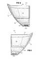
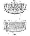
- FIG. 18is a rear perspective view of the insect trap shown in FIG. 1 with the lid in an open position;
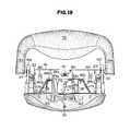
- FIG. 19is a front view of the insect trap shown in FIG. 1 with the lid in an open position;
- FIG. 20is a rear perspective view of the lid of the insect trap shown in FIG. 1 ;
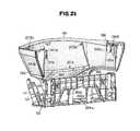
- FIG. 21is a rear perspective view of the support structure and the lid of the insect trap shown in FIG. 1 .
- a preferred embodiment insect trap constructed according to the principles of the present inventionis designated by the numeral 100 in the drawings.
- the insect trap 100is mounted on a vertical mounting surface, such as a wall, at a height above eye level.
- the insect trap 100could also be mounted on a horizontal mounting surface or any other suitable mounting surface.
- the insect trap 100is described in an orientation for mounting on a vertical mounting surface, but it is recognized that the insect trap 100 could be mounted in other orientations. Thus, the orientation described does not limit the insect trap 100 from being mounted in other orientations.
- the insect trap 100includes a housing 101 defining an opening 199 into a cavity 200 in which the insects are trapped.
- the housing 101includes a lid 190 pivotally connected to a support structure 103 , which is connected to a base 152 .
- the support structure 103includes a bottom portion 104 and a rear wall portion 116 extending upward from proximate a rear side of the bottom portion 104 .
- the bottom portion 104 and the rear wall portion 116define a cavity 126 .
- the support structure 103has a first side 105 and a second side 110 . In the orientation shown in FIG. 1 , the first side 105 is proximate the left side and the second side 110 is proximate the right side.
- the bottom portion 104includes a recessed area 104 a configured and arranged to receive a maintenance record card (not shown) proximate the front and the middle of the bottom portion 104 .
- the maintenance record cardcan simply be slid into and out of the recessed area 104 a .
- the bottom portion 104also includes a first bulb support 106 and a second bulb support 107 proximate the first side 105 and a first bulb support 111 and a second bulb support 112 proximate the second side 110 .
- the bulb supportsextend upward and outward at a forward angle from the bottom portion 104 .
- the first bulb supportspreferably extend outward from proximate the middle of the bottom portion 104 and support a first bulb 133 proximate the front side of the bottom portion 104 .
- the second bulb supportspreferably extend outward from proximate the rear side of the bottom portion 104 and support a second bulb 134 proximate the middle of the bottom portion 104 .
- the first bulb supports 106 and 111connect to and support a first bulb 133 , which extends between the first bulb supports 106 and 111 and has a connector at each end that plugs into the respective first bulb support.
- the second bulb supports 107 and 112connect to and support a second bulb 134 , which extends between the second bulb supports 107 and 112 and has a connector at each end that plugs into the respective second bulb support.
- the first bulb supports 106 and 111include bracket mounts 108 and 113 , respectively, extending outward from the rear sides of the first bulb supports 106 and 111 proximate the middle of the bottom portion 104 .
- the bracket mounts 108 and 113provide mounting surfaces for a bracket 138 , and the mounting surfaces include apertures 108 b and 113 b through which a fastener is inserted to connect the bracket 138 to the bracket mounts 108 and 113 .
- Mounting surfaces 108 a and 113 aare shown in FIG. 7 .
- the bracket mounts 108 and 113extend outward from the first bulb supports 106 and 111 proximate the second bulb supports 107 and 112 and support the bracket 138 between the bulbs 133 and 134 .
- the bracket 138is described in more detail below.
- the rear wall 116includes a first protrusion 117 proximate the top and the first side 105 and a second protrusion 119 proximate the top and the second side 110 .
- the protrusions 117 and 119are preferably triangular shaped portions extending laterally outward forwardly from the rear wall 116 .
- the first protrusion 117includes an inner surface 117 a and an outer surface 117 b .
- the inner surface 117 aincludes a raised portion 118 c between a lower depression 118 a and an upper depression 118 b .
- the outer surface 117 bincludes a receiver (not shown).
- the second protrusion 119includes an inner surface 119 a and an outer surface 119 b .
- the inner surface 119 aincludes a raised portion (not shown) between a lower depression (not shown) and an upper depression (not shown).
- the outer surface 119 bincludes a receiver 120 d .
- the depressions and the receiverscould be apertures or voids in the protrusions, and the raised portions are preferably raised relative to the depressions and are not necessarily raised relative to the inner surfaces of the protrusions.
- the rear wall 116also includes a recessed area 121 between the protrusions 117 and 119 .
- a first connector 122is preferably at least one tab extending from proximate the first side 105 inward proximate the recessed area 121
- a second connector 123is preferably at least one tab extending from proximate the second side 110 inward proximate the recessed area 121 .
- the recessed area 121is configured and arranged to receive a panel member such as a glue board or a board with a reflective surface, and the connectors 122 and 123 assist in holding the panel member within the recessed area 121 . Although three connectors 122 and 123 are shown in the drawings, any number could be used.
- the bracket 138shown in FIGS. 14-16 , is preferably a U-shaped piece with a longer bottom 139 and shorter sides 140 and 142 extending upward from the bottom 139 .
- the bottom 139includes a channel portion 139 a
- the first side 140includes a channel portion 140 a
- the second side 142includes a channel portion 142 a .
- the channel portionsare preferably elongate U-shaped channel portions configured and arranged to receive three sides of a panel member such as a glue board or a board with a reflective surface.
- a panel membersuch as a glue board or a board with a reflective surface.
- One or two panel membersmay be positioned in the bracket 138 . If two panel members are used, they should preferably be positioned back-to-back in the bracket 138 .
- the first side 140has a connector 141 extending outward therefrom, and the connector 141 includes an aperture 141 a through which a fastener is inserted to connect the connector 141 to the bracket mount 108 .
- the second side 142has a connector 143 extending outward therefrom, and the connector 143 includes an aperture 143 a through which a fastener is inserted to connect the connector 143 to the bracket mount 113 .
- the connectors 141 and 143are preferably angled to correspond with the angles of the mounting surfaces so that the bracket 138 is substantially vertically oriented.
- the base 152includes a front portion 155 that curves downward toward a bottom 153 portion and around toward sides 156 and 157 .
- a relatively flat rear portion 154interconnects the bottom portion 153 and the sides 156 and 157 .
- the front portion 155 , the bottom portion 153 , the sides 156 and 157 and the rear portion 154define a cavity 159 in which a ballast 146 is positioned.
- the front portion 155includes a first bracket 162 and a second bracket 163 , which are L-shaped protrusions facing outward away from one another, with a first aperture 161 proximate the bottom of the front portion 155 and between the brackets 162 and 163 .
- a second aperture 165 in the front portion 155is proximate the top of the front portion 155 and the second bracket 163 .
- the front portion 155also includes receptacles 164 , which are cylindrical members with bores for receiving fasteners, positioned proximate the top and proximate the middle and sides of the front portion 155 .
- the rear portion 154includes a first support 168 and a second support 169 , which are cylindrical members with bores for receiving fasteners, positioned proximate the sides of the rear portion 154 .
- the sides 156 and 157include upward extending lips 156 a and 157 a proximate the top of the sides 156 and 157 and include vents 156 b and 157 b proximate the bottom of the sides 156 and 157 .
- the vents 156 b and 157 bare optional and are shown in FIGS. 4 , 5 , and 10 .
- the bottom portion 153includes vents 171 a and 171 b and corresponding baffles 173 a and 173 b proximate the sides. Bores 172 a and 172 b receive fasteners connecting the base 152 to the support structure 103 . Between the vents 171 a and 171 b are connectors 174 , which are upwardly extending up-side down L-shaped brackets, and an exit 175 .
- a power cord 166shown in FIG. 17 , includes a first end (not shown) connected to the ballast 146 within the cavity 159 , an intermediate portion 166 a , and a second end 166 b connected to a plug 166 c .
- the intermediate portion 166 bextends through the aperture 165 , from the cavity 159 to proximate the front portion 155 , and then any excess cord is wound about the brackets 162 and 163 .
- the intermediate portion 166 athen extends through the aperture 161 , from proximate the front portion 155 into the cavity 159 .
- the connectors 174keep the intermediate portion 166 a in place within the cavity 159 , and then the intermediate portion 166 a extends out of the cavity 159 through the exit 175 to a power supply such as an outlet, into which the plug 166 c is inserted.
- the lid 190includes a front portion 191 curving downward toward a bottom portion 192 and around toward sides 193 and 194 .
- the tops of the front portion 191 and the sides 193 and 194define an opening 199 into a cavity 200 defined by the lid 190 .
- Proximate the first side 193is a first rear portion 195 a and proximate the second side 194 is a second rear portion 195 b .
- a first connector 196is connected to the first rear portion 195 a
- a second connector 197is connected to the second rear portion 195 b .
- the connectors 196 and 197are U-shaped bracket members with one side connected to the respective rear portion and extending forwardly into the cavity 200 defined by the lid 190 .
- openings in the connectors 196 and 197are proximate the rear of the lid 190 .
- the connectors 196 and 197are configured and arranged to receive the protrusions 117 and 119 of the support structure 103 .
- the first connector 196includes an inner connector 196 a proximate the inner surface 117 a of the protrusion 117 and an outer connector 196 b proximate the outer surface 117 b of the protrusion 117 .
- the second connector 197includes an inner connector 197 a proximate the inner surface 119 a of the protrusion 119 and an outer connector 197 b proximate the outer surface 119 b of the protrusion 119 . This is shown in FIG. 20 .
- the outer connectors 196 b and 197 bextend into the receivers, and the lid 190 pivots about the outer connectors 196 b and 197 b and the receivers.
- the inner connectors 196 a and 197 aextend into the lower depressions when the lid 190 is in a closed position and into the upper depressions when the lid 190 is in an open position.
- the inner connectors 196 a and 197 amove from the lower depressions over the raised portions into the upper depressions.
- the connectors 196 and 197deflect outward.
- the connectors 196 and 197move inward when the inner connectors 196 a and 197 a slide into the upper and lower depressions.
- the sides 193 and 194 of the lid 190extend over the lips 156 a and 157 a and the front portion 191 extends over a portion of the front portion 155 of the base 152 to conceal the power cord 166 wound about the brackets 162 and 163 .
- the lid 190may be disconnected from the support structure 103 without the use of tools.
- the connectors 196 and 197deflect outward, similarly as to how the connectors 196 and 197 deflect outward when the lid 190 moves between the closed and open positions, and then the inner and outer connectors are removed from the depressions and the receivers.
- the lid 190may be similarly connected to the support structure 103 .
- the inside surface of the lid 190includes a receiving portion 203 , which is preferably an angled ledge forming three sides of a rectangle, that extends outward from the lid 190 .
- the receiving portion 203is shown in FIG. 18 .
- the three sidesare angled inward and are proximate the bottom and sides of the lid 190 .
- Proximate the top of the lid 190 the receiving portion 203forms an opening and one side includes a connector 203 a and the opposing side includes a connector 203 b proximate the opening.
- the connectors 203 a and 203 bare preferably tabs extending inward from the receiving portion 203 .
- the connectors 203 a and 203 bare preferably also angled so that the bottoms are closer to the lid 190 than the tops of the connectors 203 a and 203 b .
- the receiving portion 203is configured and arranged to receive a panel member.
- the panel memberis preferably slid through the opening so that the three sides of the receiving portion 203 support the corresponding sides of the panel member and the connectors 203 a and 203 b hold the panel member against the lid 190 .
- the rear wall portion 116 of the support structure 103could also include receiving portions 184 a , 184 b , and 184 c and an aperture 185 configured and arranged to receive portions of a mounting plate 177 .
- FIGS. 1 , 2 , 9 , and 11do not show these features of the rear wall portion 116 .
- the receiving portion 184 ais preferably a generally isosceles trapezoid shaped opening with a notched portion proximate the top.
- the receiving portion 184 ais in the middle of receiving portions 184 b and 184 c , which are preferably mirror images of one another.
- the receiving portions 184 b and 184 care preferably generally trapezoid shaped openings with the outer sides having smaller angles relative to the tops and bottoms than the inner sides.
- Above the middle receiving portion 184 ais a rectangular shaped aperture 185 .
- Proximate the tops and the sides of the side receiving portions 184 b and 184 care apertures 186 , which could be used for mounting the rear wall portion 116 directly to a mounting surface.
- the mounting plate 177could be used to mount the housing 101 onto a mounting surface such as a wall.
- the mounting plate 177is preferably an isosceles trapezoidal shaped plate with the top being shorter than the bottom.
- the mounting plate 177includes a supporting portion 182 , which preferably includes three raised portions 182 a , 182 b , and 182 c corresponding with the receiving portions 184 a , 184 b , and 184 c .
- a first aperture 178which is preferably key-hole shaped, is proximate the middle of the raised portion 182 a
- a side aperture 179is proximate the middle of each raised portion 182 b and 182 c .
- a leveling device 180preferably a bubble level, is proximate below the first aperture 178 .
- a quick release member 181extends upward from proximate the middle and the top of the raised portion 182 a , and includes a ledge 181 a extending outward forwardly therefrom.
- the quick release member 181corresponds with the aperture 185 , and the ledge 181 a extends outward proximate the bottom of the aperture 185 .
- the quick release member 181is preferably pliable.
- a fastener(not shown) is inserted into the mounting surface in the desired location, and then the fastener is inserted through the larger portion of the first aperture 178 .
- the mounting plate 177is then slid downward so that the fastener extends through the smaller portion of the first aperture 178 .
- the mounting plate 177is then leveled using the leveling device 180 . Once the mounting plate 177 is level, fasteners are inserted through the apertures 179 and into the mounting surface.
- the rear wall portion 116is placed against the mounting plate 177 with the receiving portions 184 a , 184 b , and 184 c positioned above the corresponding raised portions 182 a , 182 b , and 182 c .
- the rear wall portion 116is then moved downward so that the raised portions 182 a , 182 b , and 182 c slide into the receiving portions 184 a , 184 b , and 184 c .
- the quick release member 181When the rear wall portion 116 is pushed against the mounting plate 177 , the quick release member 181 is deflected backwardly, and when the raised portions 182 a , 182 b , and 182 c slide into the receiving portions 184 a , 184 b , and 184 c , the quick release member 181 moves back into position so that at least a portion of the ledge 181 a overlaps with the bottom of the aperture 185 . The rear wall portion 116 may then be released.
- the rear wall portion 116 proximate the top of the receiving portion 184 acontacts the top of the raised portion 182 a and the rear wall portion 116 proximate the tops and the sides of the receiving portions 184 b and 184 c contact the corresponding tops and sides of the raised portions 182 b and 182 c to support the rear wall portion 116 on the mounting surface.
- the insect trap 100could be mounted to a mounting surface using the mounting plate 177 or by mounting the rear wall portion 116 directly to the mounting surface.
- the opening 199is preferably discrete and positioned so that it faces upwardly proximate the top of the insect trap 100 .
- the quick release member 181is pushed backward so that the ledge 181 a no longer overlaps with the bottom of the aperture 185 .
- the rear wall portion 116may then be moved upward so that the raised portions 182 a , 182 b , and 182 c do not extend into the receiving portions 184 a , 184 b , and 184 c . If the insect trap 100 , excluding the mounting plate 177 , needs to be repaired or replaced, another insect trap 100 could be hung on the same mounting plate 177 without the use of any tools and without putting any additional holes into the mounting surface.
- the insect trap 100is configured and arranged to receive up to five panel members, which could be glue boards or boards with reflective surfaces.
- FIG. 11shows a first panel member 127 positioned on the bottom surface 104 of the support structure 103 .
- a maintenance record cardcould be positioned within the recessed area 104 a underneath the first panel member 127 .
- FIG. 12shows a second panel member 128 within the recessed area 121 of the rear wall portion 116 .
- FIGS. 12 and 13show a third panel member 129 as it would be positioned if the lid 190 were connected and in the closed position.
- FIG. 13shows back-to-back fourth and fifth panel members 130 and 131 in the bracket 138 .
- FIGS. 11-13are illustrative and it is recognized that the placements and numbers of the panel members in the insect trap 100 are not limited by these illustrations. The number and the type of panel members used depend upon the need. For increased capacity, a higher number of panel members should be used.
- the length of the power cord 166is easily adjustable to accommodate varying distances between the desired location for mounting the insect trap 100 on a mounting surface and the power supply. If it is desired to lengthen the power cord 166 , the power cord 166 is unwound from the brackets 162 and 163 and then simply pulled through the aperture 161 , the connectors 174 , and the exit 175 . It may be necessary to first create some slack in the power cord 166 by pulling the power cord through the exit 175 , the connectors 174 , and the aperture 161 . To shorten the length of the power cord 166 , the power cord is pulled through the exit 175 , the connectors 174 , and the aperture 161 and then wound about the brackets 162 and 163 . When the lid 190 is closed, the portion of the power cord 166 wound about the brackets 162 and 163 is covered by the lid 190 .
- the lid 190When performing maintenance on the insect trap 100 , such as replacing glue boards or light bulbs, the lid 190 is moved from the closed position to the open position. The lid 190 stays in the open position until a downward force is applied to the lid 190 , which deflects the connectors 196 and 197 outward as the inner connectors 196 a and 197 a move out of the upper depressions and over the raised portions. The connectors 196 and 197 move inward as the inner connectors 196 a and 197 a move into the lower depressions.
- the insect trap 100allows for improved serviceability.
- the lid 190which stays in the open position, allows the service provider to use both hands to service the insect trap 100 .
- the adjustable length of the power cord 166allows the insect trap 100 to be mounted at varying lengths from the power source and allows any excess length to be concealed by the lid 190 .
- the mounting plate 177Once the mounting plate 177 has been connected to a mounting surface, the mounting plate 177 allows the insect trap 100 to be connected and disconnected to the mounting surface without the use of tools.
- the mounting plate 177also assists in mounting the insect trap 100 so that it is level. Also, the number of panel members may be varying depending upon the need. Further, the maintenance record card is accessible to assist in maintaining accurate maintenance records.
Landscapes
- Life Sciences & Earth Sciences (AREA)
- Pest Control & Pesticides (AREA)
- Engineering & Computer Science (AREA)
- Insects & Arthropods (AREA)
- Wood Science & Technology (AREA)
- Zoology (AREA)
- Environmental Sciences (AREA)
- Catching Or Destruction (AREA)
Abstract
Description
The present invention relates to an insect trap and, more particularly, to a flying insect trap.
Flying insect traps with insect attractant light sources and immobilization devices are commonly used to attract and trap flying insects within the traps. The present invention addresses the problems associated with the prior art devices and provides for an improved insect trap.
One aspect of the present invention provides an insect trap including a support structure, a lid, and a first source of insect attractant light. The support structure includes a bottom portion and a rear portion extending upward from a rear of the bottom portion. The rear portion includes a first connector. The lid is pivotally connected to the rear portion, and the lid includes an inside surface with a second connector. The support structure and the lid define a cavity. The first source of insect attractant light is supported by the support structure within the cavity. The bottom portion is configured and arranged to receive a first panel member, the first connector is configured and arranged to receive a second panel member, and the second connector is configured and arranged to receive a third panel member.
Another aspect of the present invention provides an insect trap including a support structure, a lid, a first source of insect attractant light, and a bracket. The support structure includes a bottom portion and a rear portion extending upward from a rear of the bottom portion. The rear portion includes a first connector. The lid is pivotally connected to the rear portion, and the lid includes an inside surface with a second connector. The support structure and the lid define a cavity. The first source of insect attractant light is supported by the support structure within the cavity. The bracket is connected to the bottom portion proximate the first source of insect attractant light, and the bracket includes a third connector. The third connector is positioned between the first connector and the second connector. The bottom portion is configured and arranged to receive a first panel member, the first connector is configured and arranged to receive a second panel member, the second connector is configured and arranged to receive a third panel member, and the third connector is configured and arranged to receive a fourth panel member.
Another aspect of the present invention provides a method of installing an insect trap. A mounting bracket having an integral leveling device, a supporting portion, a first aperture, and a second aperture is obtained. A first fastener is inserted into a mounting surface. The first fastener is inserted through the first aperture in the mounting bracket and the mounting bracket is positioned on the mounting surface. The mounting bracket is leveled with the leveling device. A second fastener is inserted through the second aperture and into the mounting surface. A housing having a receiving portion is obtained. The receiving portion is configured and arranged to receive the supporting portion and releasably connect the housing to the mounting bracket. The supporting portion is inserted into the receiving portion thereby releasably connecting the housing to the mounting bracket.
Another aspect of the present invention provides an insect trap including a housing, a ballast, and a power cord. The housing includes a support structure with a top and a bottom. The top is pivotally connected to a lid, and the bottom is connected to a base. The base has a cavity, a front side, and a bottom side. The front side includes a first aperture, a second aperture, and a bracket. The bottom side includes a third aperture. The ballast is positioned in the cavity. The power cord includes a first end, a second end, and an intermediate portion. The first end is connected to the ballast. A portion of the intermediate portion extends through the first aperture from the cavity to the front side, is wound about the bracket, extends through the second aperture from the front side to the cavity, and extends through the third aperture from the cavity to proximate the bottom side. The second end includes a plug. The lid extends over the front side thereby covering the portion of the intermediate portion of the power cord proximate the front side. The intermediate portion is windable and unwindable about the bracket to adjust a length of the intermediate portion from proximate the third aperture to the second end.
Another aspect of the present invention provides an insect trap comprising a housing including a support structure and a lid defining a cavity. The housing has a top, a first side, and a second side. The support structure includes a bottom portion and a rear portion extending upward from a rear of the bottom portion. The rear portion has a first protrusion proximate the top and the first side and a second protrusion proximate the top and the second side. The first protrusion has a first inner surface and a first outer surface and the second protrusion has a second inner surface and a second outer surface. The first inner surface has a first lower depression and a first upper depression with a first raised portion between the first lower depression and the first upper depression, and the first outer surface has a first receiver. The second inner surface has a second lower depression and a second upper depression with a second raised portion between the second lower depression and the second upper depression, and the second outer surface has a second receiver. The lid includes a first connecting member proximate the first side and a second connecting member proximate the second side. The first connecting member has a first outer connector and a first inner connector. The first receiver receives the first outer connector, and the first inner connector is configured and arranged to move between the first lower depression and the first upper depression. The second connecting member has a second outer connector and a second inner connector. The second receiver receives the second outer connector, and the second inner connector is configured and arranged to move between the second lower depression and the second upper depression. The lid is pivotally connected to the rear portion about the outer connectors and has a closed position and an open position. The lid is in the closed position when the inner connectors are in the lower depressions, and the lid is in the open position when the inner connectors are in the upper depressions. The connecting member deflects outward proximate the inner connectors as the inner connectors move over the raised portions. The upper depressions hold the lid in the open position.
A preferred embodiment insect trap constructed according to the principles of the present invention is designated by the numeral100 in the drawings.
Preferably, theinsect trap 100 is mounted on a vertical mounting surface, such as a wall, at a height above eye level. However, theinsect trap 100 could also be mounted on a horizontal mounting surface or any other suitable mounting surface. Throughout this description, theinsect trap 100 is described in an orientation for mounting on a vertical mounting surface, but it is recognized that theinsect trap 100 could be mounted in other orientations. Thus, the orientation described does not limit theinsect trap 100 from being mounted in other orientations.
Theinsect trap 100 includes ahousing 101 defining anopening 199 into acavity 200 in which the insects are trapped. Thehousing 101 includes alid 190 pivotally connected to asupport structure 103, which is connected to abase 152. Thesupport structure 103 includes abottom portion 104 and arear wall portion 116 extending upward from proximate a rear side of thebottom portion 104. Thebottom portion 104 and therear wall portion 116 define acavity 126. Thesupport structure 103 has afirst side 105 and asecond side 110. In the orientation shown inFIG. 1 , thefirst side 105 is proximate the left side and thesecond side 110 is proximate the right side.
Thebottom portion 104 includes a recessedarea 104aconfigured and arranged to receive a maintenance record card (not shown) proximate the front and the middle of thebottom portion 104. Preferably, the maintenance record card can simply be slid into and out of the recessedarea 104a. Thebottom portion 104 also includes afirst bulb support 106 and asecond bulb support 107 proximate thefirst side 105 and a first bulb support111 and asecond bulb support 112 proximate thesecond side 110. Preferably, the bulb supports extend upward and outward at a forward angle from thebottom portion 104.
The first bulb supports preferably extend outward from proximate the middle of thebottom portion 104 and support afirst bulb 133 proximate the front side of thebottom portion 104. The second bulb supports preferably extend outward from proximate the rear side of thebottom portion 104 and support asecond bulb 134 proximate the middle of thebottom portion 104.
The first bulb supports106 and111 connect to and support afirst bulb 133, which extends between the first bulb supports106 and111 and has a connector at each end that plugs into the respective first bulb support. The second bulb supports107 and112 connect to and support asecond bulb 134, which extends between the second bulb supports107 and112 and has a connector at each end that plugs into the respective second bulb support.
The first bulb supports106 and111 include bracket mounts108 and113, respectively, extending outward from the rear sides of the first bulb supports106 and111 proximate the middle of thebottom portion 104. The bracket mounts108 and113 provide mounting surfaces for abracket 138, and the mounting surfaces include apertures108band113bthrough which a fastener is inserted to connect thebracket 138 to the bracket mounts108 and113. Mountingsurfaces 108aand113aare shown inFIG. 7 . The bracket mounts108 and113 extend outward from the first bulb supports106 and111 proximate the second bulb supports107 and112 and support thebracket 138 between thebulbs bracket 138 is described in more detail below.
Therear wall 116 includes afirst protrusion 117 proximate the top and thefirst side 105 and asecond protrusion 119 proximate the top and thesecond side 110. Theprotrusions rear wall 116. Thefirst protrusion 117 includes an inner surface117aand anouter surface 117b. The inner surface117aincludes a raisedportion 118cbetween alower depression 118aand anupper depression 118b. Theouter surface 117bincludes a receiver (not shown). Thesecond protrusion 119 includes aninner surface 119aand anouter surface 119b. Theinner surface 119aincludes a raised portion (not shown) between a lower depression (not shown) and an upper depression (not shown). Theouter surface 119bincludes areceiver 120d. The depressions and the receivers could be apertures or voids in the protrusions, and the raised portions are preferably raised relative to the depressions and are not necessarily raised relative to the inner surfaces of the protrusions.
Therear wall 116 also includes a recessedarea 121 between theprotrusions first connector 122 is preferably at least one tab extending from proximate thefirst side 105 inward proximate the recessedarea 121, and asecond connector 123 is preferably at least one tab extending from proximate thesecond side 110 inward proximate the recessedarea 121. The recessedarea 121 is configured and arranged to receive a panel member such as a glue board or a board with a reflective surface, and theconnectors area 121. Although threeconnectors
Thebracket 138, shown inFIGS. 14-16 , is preferably a U-shaped piece with alonger bottom 139 andshorter sides
The bottom139 includes achannel portion 139a, thefirst side 140 includes achannel portion 140a, and thesecond side 142 includes achannel portion 142a. The channel portions are preferably elongate U-shaped channel portions configured and arranged to receive three sides of a panel member such as a glue board or a board with a reflective surface. One or two panel members may be positioned in thebracket 138. If two panel members are used, they should preferably be positioned back-to-back in thebracket 138. Thefirst side 140 has aconnector 141 extending outward therefrom, and theconnector 141 includes anaperture 141athrough which a fastener is inserted to connect theconnector 141 to thebracket mount 108. Thesecond side 142 has aconnector 143 extending outward therefrom, and theconnector 143 includes an aperture143athrough which a fastener is inserted to connect theconnector 143 to thebracket mount 113. Theconnectors bracket 138 is substantially vertically oriented.
Thebase 152 includes afront portion 155 that curves downward toward a bottom153 portion and around towardsides rear portion 154 interconnects thebottom portion 153 and thesides front portion 155, thebottom portion 153, thesides rear portion 154 define acavity 159 in which aballast 146 is positioned. Thefront portion 155 includes afirst bracket 162 and asecond bracket 163, which are L-shaped protrusions facing outward away from one another, with afirst aperture 161 proximate the bottom of thefront portion 155 and between thebrackets second aperture 165 in thefront portion 155 is proximate the top of thefront portion 155 and thesecond bracket 163. Thefront portion 155 also includesreceptacles 164, which are cylindrical members with bores for receiving fasteners, positioned proximate the top and proximate the middle and sides of thefront portion 155. Therear portion 154 includes afirst support 168 and asecond support 169, which are cylindrical members with bores for receiving fasteners, positioned proximate the sides of therear portion 154. Fasteners (not shown) extend through apertures (not shown) in thebottom portion 104 of thesupport structure 103 and into the bores of thereceptacles 164 and thesupports support structure 103 to thebase 152. Thesides lips sides vents sides vents FIGS. 4 ,5, and10.
As shown inFIG. 8 , thebottom portion 153 includesvents corresponding baffles 173aand173bproximate the sides.Bores 172aand172breceive fasteners connecting the base152 to thesupport structure 103. Between thevents exit 175. Apower cord 166, shown inFIG. 17 , includes a first end (not shown) connected to theballast 146 within thecavity 159, anintermediate portion 166a, and a second end166bconnected to aplug 166c. The intermediate portion166bextends through theaperture 165, from thecavity 159 to proximate thefront portion 155, and then any excess cord is wound about thebrackets intermediate portion 166athen extends through theaperture 161, from proximate thefront portion 155 into thecavity 159. The connectors174 keep theintermediate portion 166ain place within thecavity 159, and then theintermediate portion 166aextends out of thecavity 159 through theexit 175 to a power supply such as an outlet, into which theplug 166cis inserted.
Thelid 190 includes afront portion 191 curving downward toward abottom portion 192 and around towardsides front portion 191 and thesides opening 199 into acavity 200 defined by thelid 190. Proximate thefirst side 193 is a firstrear portion 195aand proximate thesecond side 194 is a secondrear portion 195b. Afirst connector 196 is connected to the firstrear portion 195a, and asecond connector 197 is connected to the secondrear portion 195b. Theconnectors cavity 200 defined by thelid 190. Thus, openings in theconnectors lid 190.
Theconnectors protrusions support structure 103. Thefirst connector 196 includes aninner connector 196aproximate the inner surface117aof theprotrusion 117 and anouter connector 196bproximate theouter surface 117bof theprotrusion 117. Thesecond connector 197 includes aninner connector 197aproximate theinner surface 119aof theprotrusion 119 and anouter connector 197bproximate theouter surface 119bof theprotrusion 119. This is shown inFIG. 20 . Theouter connectors lid 190 pivots about theouter connectors inner connectors lid 190 is in a closed position and into the upper depressions when thelid 190 is in an open position. As thelid 190 pivots upward and downward between the closed and open positions, theinner connectors connectors connectors connectors inner connectors sides lid 190 extend over thelips front portion 191 extends over a portion of thefront portion 155 of the base152 to conceal thepower cord 166 wound about thebrackets
Further, thelid 190 may be disconnected from thesupport structure 103 without the use of tools. Theconnectors connectors lid 190 moves between the closed and open positions, and then the inner and outer connectors are removed from the depressions and the receivers. Thelid 190 may be similarly connected to thesupport structure 103.
The inside surface of thelid 190 includes a receivingportion 203, which is preferably an angled ledge forming three sides of a rectangle, that extends outward from thelid 190. The receivingportion 203 is shown inFIG. 18 . The three sides are angled inward and are proximate the bottom and sides of thelid 190. Proximate the top of thelid 190 the receivingportion 203 forms an opening and one side includes aconnector 203aand the opposing side includes aconnector 203bproximate the opening. Theconnectors portion 203. Theconnectors lid 190 than the tops of theconnectors portion 203 is configured and arranged to receive a panel member. The panel member is preferably slid through the opening so that the three sides of the receivingportion 203 support the corresponding sides of the panel member and theconnectors lid 190.
As shown inFIG. 19 , therear wall portion 116 of thesupport structure 103 could also include receivingportions aperture 185 configured and arranged to receive portions of a mountingplate 177.FIGS. 1 ,2,9, and11 do not show these features of therear wall portion 116. The receivingportion 184ais preferably a generally isosceles trapezoid shaped opening with a notched portion proximate the top. The receivingportion 184ais in the middle of receivingportions portions middle receiving portion 184ais a rectangular shapedaperture 185. Proximate the tops and the sides of theside receiving portions apertures 186, which could be used for mounting therear wall portion 116 directly to a mounting surface.
The mountingplate 177 could be used to mount thehousing 101 onto a mounting surface such as a wall. The mountingplate 177 is preferably an isosceles trapezoidal shaped plate with the top being shorter than the bottom. The mountingplate 177 includes a supportingportion 182, which preferably includes three raisedportions portions first aperture 178, which is preferably key-hole shaped, is proximate the middle of the raisedportion 182a, and aside aperture 179 is proximate the middle of each raisedportion leveling device 180, preferably a bubble level, is proximate below thefirst aperture 178. Aquick release member 181 extends upward from proximate the middle and the top of the raisedportion 182a, and includes aledge 181aextending outward forwardly therefrom. Thequick release member 181 corresponds with theaperture 185, and theledge 181aextends outward proximate the bottom of theaperture 185. Thequick release member 181 is preferably pliable.
To mount the mountingplate 177 to a mounting surface, a fastener (not shown) is inserted into the mounting surface in the desired location, and then the fastener is inserted through the larger portion of thefirst aperture 178. The mountingplate 177 is then slid downward so that the fastener extends through the smaller portion of thefirst aperture 178. The mountingplate 177 is then leveled using theleveling device 180. Once the mountingplate 177 is level, fasteners are inserted through theapertures 179 and into the mounting surface.
To attach therear wall portion 116 to the mountingplate 177, therear wall portion 116 is placed against the mountingplate 177 with the receivingportions portions rear wall portion 116 is then moved downward so that the raisedportions portions rear wall portion 116 is pushed against the mountingplate 177, thequick release member 181 is deflected backwardly, and when the raisedportions portions quick release member 181 moves back into position so that at least a portion of theledge 181aoverlaps with the bottom of theaperture 185. Therear wall portion 116 may then be released. Therear wall portion 116 proximate the top of the receivingportion 184acontacts the top of the raisedportion 182aand therear wall portion 116 proximate the tops and the sides of the receivingportions portions rear wall portion 116 on the mounting surface. Once therear wall portion 116 is thus engaged by the mountingplate 177, the rear wall portion cannot be moved in a downward direction because of the raisedportions quick release member 181.
Theinsect trap 100 could be mounted to a mounting surface using the mountingplate 177 or by mounting therear wall portion 116 directly to the mounting surface. When theinsect trap 100 is mounted on a vertical mounting surface, theopening 199 is preferably discrete and positioned so that it faces upwardly proximate the top of theinsect trap 100.
To release therear wall portion 116 from the mountingplate 177, thequick release member 181 is pushed backward so that theledge 181ano longer overlaps with the bottom of theaperture 185. Therear wall portion 116 may then be moved upward so that the raisedportions portions insect trap 100, excluding the mountingplate 177, needs to be repaired or replaced, anotherinsect trap 100 could be hung on the same mountingplate 177 without the use of any tools and without putting any additional holes into the mounting surface.
Theinsect trap 100 is configured and arranged to receive up to five panel members, which could be glue boards or boards with reflective surfaces.FIG. 11 shows afirst panel member 127 positioned on thebottom surface 104 of thesupport structure 103. A maintenance record card could be positioned within the recessedarea 104aunderneath thefirst panel member 127.FIG. 12 shows asecond panel member 128 within the recessedarea 121 of therear wall portion 116. Although thelid 190 is not shown,FIGS. 12 and 13 show athird panel member 129 as it would be positioned if thelid 190 were connected and in the closed position.FIG. 13 shows back-to-back fourth andfifth panel members bracket 138.FIGS. 11-13 are illustrative and it is recognized that the placements and numbers of the panel members in theinsect trap 100 are not limited by these illustrations. The number and the type of panel members used depend upon the need. For increased capacity, a higher number of panel members should be used.
The length of thepower cord 166 is easily adjustable to accommodate varying distances between the desired location for mounting theinsect trap 100 on a mounting surface and the power supply. If it is desired to lengthen thepower cord 166, thepower cord 166 is unwound from thebrackets aperture 161, the connectors174, and theexit 175. It may be necessary to first create some slack in thepower cord 166 by pulling the power cord through theexit 175, the connectors174, and theaperture 161. To shorten the length of thepower cord 166, the power cord is pulled through theexit 175, the connectors174, and theaperture 161 and then wound about thebrackets lid 190 is closed, the portion of thepower cord 166 wound about thebrackets lid 190.
When performing maintenance on theinsect trap 100, such as replacing glue boards or light bulbs, thelid 190 is moved from the closed position to the open position. Thelid 190 stays in the open position until a downward force is applied to thelid 190, which deflects theconnectors inner connectors connectors inner connectors
Theinsect trap 100 allows for improved serviceability. Thelid 190, which stays in the open position, allows the service provider to use both hands to service theinsect trap 100. The adjustable length of thepower cord 166 allows theinsect trap 100 to be mounted at varying lengths from the power source and allows any excess length to be concealed by thelid 190. Once the mountingplate 177 has been connected to a mounting surface, the mountingplate 177 allows theinsect trap 100 to be connected and disconnected to the mounting surface without the use of tools. The mountingplate 177 also assists in mounting theinsect trap 100 so that it is level. Also, the number of panel members may be varying depending upon the need. Further, the maintenance record card is accessible to assist in maintaining accurate maintenance records.
The above specification, examples and data provide a complete description of the manufacture and use of the composition of the invention. Since many embodiments of the invention can be made without departing from the spirit and scope of the invention, the invention resides in the claims hereinafter appended.
Claims (7)
1. An insect trap, comprising:
a support structure including a bottom portion and a rear portion extending upward from a rear of the bottom portion, the rear portion including a first connector;
a lid pivotally connected to the rear portion, the lid including an inside surface with a second connector, the support structure and the lid defining a cavity;
a first source of insect attractant light supported by the support structure within the cavity;
a bracket mount extending upward from the bottom portion proximate the first source of insect attractant light;
a U-shaped bracket operatively and releasably connected to the bracket mount, the bracket including a bottom and sides extending upward from the bottom to form a third connector, the third connector including a channel portion and being positioned between the first connector and the second connector; and
wherein the bottom portion is configured and arranged to receive a first panel member, the first connector is configured and arranged to receive a second panel member, the second connector is configured and arranged to receive a third panel member, and the third connector is configured and arranged to receive a fourth panel member, the fourth panel member being received in the channel portion.
2. The insect trap ofclaim 1 , wherein at least one of the panel members is a member selected from the group consisting of a glue board and a board having a reflective surface.
3. The insect trap ofclaim 1 , wherein the fourth panel member is a first glue board and a second glue board, the first and second glue boards being back-to-back and facing away from one another.
4. The insect trap ofclaim 1 , further comprising a second source of insect attractant light supported by the support structure within the cavity, wherein the bracket is positioned between the first and second sources of insect attractant light.
5. The insect trap ofclaim 1 , wherein at least one of the bracket and the fourth panel member is retrofittable and removable depending upon need.
6. An insect trap, comprising:
a housing including a support structure and a lid defining a cavity, the housing having a top, a first side, and a second side;
the support structure includes a bottom portion and a rear portion extending upward from a rear of the bottom portion, the rear portion having a first protrusion proximate the top and the first side and a second protrusion proximate the top and the second side, the first protrusion having a first inner surface and a first outer surface and the second protrusion having a second inner surface and a second outer surface, the first inner surface having a first lower depression and a first upper depression with a first raised portion between the first lower depression and the first upper depression, the first outer surface having a first receiver, the second inner surface having a second lower depression and a second upper depression with a second raised portion between the second lower depression and the second upper depression, the second outer surface having a second receiver;
the lid includes a first connecting member proximate the first side and a second connecting member proximate the second side, the first connecting member having a first outer connector and a first inner connector, the first receiver receiving the first outer connector, the first inner connector being configured and arranged to move between the first lower depression and the first upper depression, the second connecting member having a second outer connector and a second inner connector, the second receiver receiving the second outer connector, the second inner connector being configured and arranged to move between the second lower depression and the second upper depression, the lid being pivotally connected to the rear portion about the outer connectors and having a closed position and an open position, the lid being in the closed position when the inner connectors are in the lower depressions, the lid being in the open position when the inner connectors are in the upper depressions, wherein the connecting member deflects outward proximate the inner connectors as the inner connectors move over the raised portions, the upper depressions holding the lid in the open position.
7. The insect trap ofclaim 6 , wherein the connecting members are U-shaped brackets with opposing sides, the outer connectors and the inner connectors extend outward from the opposing sides toward one another.
Priority Applications (1)
| Application Number | Priority Date | Filing Date | Title |
|---|---|---|---|
| US11/928,623US8572890B1 (en) | 2007-10-30 | 2007-10-30 | Insect trap |
Applications Claiming Priority (1)
| Application Number | Priority Date | Filing Date | Title |
|---|---|---|---|
| US11/928,623US8572890B1 (en) | 2007-10-30 | 2007-10-30 | Insect trap |
Publications (1)
| Publication Number | Publication Date |
|---|---|
| US8572890B1true US8572890B1 (en) | 2013-11-05 |
Family
ID=49487657
Family Applications (1)
| Application Number | Title | Priority Date | Filing Date |
|---|---|---|---|
| US11/928,623Active2029-12-15US8572890B1 (en) | 2007-10-30 | 2007-10-30 | Insect trap |
Country Status (1)
| Country | Link |
|---|---|
| US (1) | US8572890B1 (en) |
Cited By (25)
| Publication number | Priority date | Publication date | Assignee | Title |
|---|---|---|---|---|
| US20120317868A1 (en)* | 2011-06-15 | 2012-12-20 | Ecolab Usa Inc. | Flying insect attraction station |
| US20140223803A1 (en)* | 2011-09-20 | 2014-08-14 | Hamamatsu University School Of Medicine | Attraction device, insect-capturing apparatus and insect-capturing method |
| US9883666B1 (en)* | 2014-09-15 | 2018-02-06 | David A. Conklin | Flying insect trap |
| USD818559S1 (en) | 2016-05-20 | 2018-05-22 | Ecolab Usa Inc. | Insect trap |
| US10292379B2 (en)* | 2011-06-15 | 2019-05-21 | Ecolab Usa Inc. | Flying insect attraction station |
| USD856467S1 (en)* | 2018-04-27 | 2019-08-13 | Casey J. Bishop | Insect trap |
| US10561135B2 (en) | 2015-01-12 | 2020-02-18 | The Procter & Gamble Company | Insect trap device and method of using |
| US10568314B2 (en) | 2013-11-27 | 2020-02-25 | The Procter & Gamble Company | Insect trap device and method of using |
| US10588307B2 (en) | 2014-04-26 | 2020-03-17 | The Procter & Gamble Company | Insect trap device and method of using |
| US11109583B2 (en)* | 2019-02-14 | 2021-09-07 | KP Solutions, Inc. | Insect trapping light |
| US20220061301A1 (en)* | 2020-08-31 | 2022-03-03 | The Procter & Gamble Company | Arthropod trapping device |
| US11311005B2 (en)* | 2016-07-11 | 2022-04-26 | The Procter & Gamble Company | Heated insect trapping device and methods thereof |
| US20220225600A1 (en)* | 2021-01-19 | 2022-07-21 | Guadalupe Gonzalez | Insect Trapping Device And Method Of Use |
| US11445716B2 (en) | 2013-03-01 | 2022-09-20 | The Procter & Gamble Company | Insect trap device and method of using |
| US11484022B2 (en) | 2019-10-15 | 2022-11-01 | S. C. Johnson & Son, Inc. | Insect trap device |
| US11582964B2 (en)* | 2016-11-21 | 2023-02-21 | Rentokil Initial 1927 Plc | Insect trap |
| USD988462S1 (en) | 2020-08-31 | 2023-06-06 | The Procter & Gamble Company | Insert for an arthropod trapping device |
| US20230309540A1 (en)* | 2022-03-02 | 2023-10-05 | The Procter & Gamble Company | Arthropod trapping device |
| USD1004738S1 (en)* | 2022-04-20 | 2023-11-14 | Bugmd Llc | Insect trap |
| USD1036613S1 (en) | 2021-06-25 | 2024-07-23 | The Procter & Gamble Company | Transparent insert for an arthropod trapping device |
| US12096758B1 (en)* | 2023-03-21 | 2024-09-24 | Gardner Manufacturing Co., Inc. | Insect trap installation and leveling bracket and method |
| USD1043899S1 (en) | 2020-08-31 | 2024-09-24 | The Procter & Gamble Company | Housing for an arthropod trapping device |
| USD1043900S1 (en)* | 2022-07-27 | 2024-09-24 | Bugmd Llc | Insect trap |
| US12250937B2 (en) | 2015-05-29 | 2025-03-18 | Ecolab Usa Inc. | Device and method for attracting and trapping flying insects |
| US12290060B2 (en) | 2019-10-15 | 2025-05-06 | S. C. Johnson & Son, Inc. | Insect trap device |
Citations (25)
| Publication number | Priority date | Publication date | Assignee | Title |
|---|---|---|---|---|
| US1792774A (en)* | 1928-12-13 | 1931-02-17 | George R Cooper | Mouse trap |
| US4074457A (en)* | 1975-05-12 | 1978-02-21 | Kawaguchiko Seimitsu Co., Ltd. | Insects catcher assembly |
| US4117624A (en)* | 1977-07-25 | 1978-10-03 | Pestolite, Inc. | Insect trap |
| US4709503A (en)* | 1985-10-21 | 1987-12-01 | Mcqueen Robert | Crawling insect trap |
| US4776822A (en)* | 1987-11-12 | 1988-10-11 | Zenith Electronics Corporation | Registration transfer process for use in the manufacture of a tension mask color cathode ray tube |
| US4815231A (en)* | 1985-10-21 | 1989-03-28 | Mcqueen Robert | Trap for small crawling pests |
| US5325625A (en)* | 1993-09-09 | 1994-07-05 | University Of Kentucky Research Foundation | Automated adjustable interval insect trap |
| US5365690A (en)* | 1993-01-04 | 1994-11-22 | Ecolab, Inc. | Flying insect trap using reflected and radiated light |
| US5438792A (en)* | 1994-01-25 | 1995-08-08 | Robert Blackman | Insect traps |
| US5513465A (en)* | 1993-12-17 | 1996-05-07 | S. C. Johnson & Son, Inc. | Method and apparatus for catching insects |
| US5651211A (en)* | 1995-05-12 | 1997-07-29 | Regan; Harold R. | Wall mounted trap for flies and insects |
| US5713153A (en)* | 1994-05-24 | 1998-02-03 | Us Agriculture | Insect trap containing olfactory lure |
| US5974727A (en) | 1998-11-06 | 1999-11-02 | Gilbert Industries | Decorative flying insect trap |
| US20010013194A1 (en)* | 1996-09-13 | 2001-08-16 | John Llewellyn Greening | Insect catching device |
| US20020032980A1 (en)* | 1993-01-04 | 2002-03-21 | Ecolab Inc. | Light trap for insects |
| US6393759B1 (en)* | 2000-01-21 | 2002-05-28 | Jeffrey K. Brown | Electronic fly trap apparatus with cover |
| US20020078620A1 (en)* | 1993-01-04 | 2002-06-27 | Ecolab Inc. | Fly trap with multiple light patterns |
| US6442889B1 (en)* | 1998-10-20 | 2002-09-03 | Elliot W. Lee | Insect and animal traps and holder for same |
| US6493986B1 (en)* | 1993-01-04 | 2002-12-17 | Ecolab Inc. | Light trap for insects |
| US20030089024A1 (en)* | 2002-10-11 | 2003-05-15 | Nelson Thomas D. | Light trap for insects |
| US20040159040A1 (en)* | 2003-02-13 | 2004-08-19 | Chen Chung Ming | Mosquito trap |
| USD498286S1 (en) | 2002-10-11 | 2004-11-09 | Ecolab Inc. | Insect trap housing portion |
| US20050126069A1 (en)* | 2003-12-12 | 2005-06-16 | Paraclipse, Inc., A Nebraska Corporation | Flying insect trap |
| US20060080888A1 (en)* | 2004-10-15 | 2006-04-20 | Greening John L | Flying insect trap |
| US7036268B2 (en) | 2003-04-30 | 2006-05-02 | Paraclipse, Inc. | Flying insect trap |
- 2007
- 2007-10-30USUS11/928,623patent/US8572890B1/enactiveActive
Patent Citations (33)
| Publication number | Priority date | Publication date | Assignee | Title |
|---|---|---|---|---|
| US1792774A (en)* | 1928-12-13 | 1931-02-17 | George R Cooper | Mouse trap |
| US4074457A (en)* | 1975-05-12 | 1978-02-21 | Kawaguchiko Seimitsu Co., Ltd. | Insects catcher assembly |
| US4117624A (en)* | 1977-07-25 | 1978-10-03 | Pestolite, Inc. | Insect trap |
| US4709503A (en)* | 1985-10-21 | 1987-12-01 | Mcqueen Robert | Crawling insect trap |
| US4815231A (en)* | 1985-10-21 | 1989-03-28 | Mcqueen Robert | Trap for small crawling pests |
| US4776822A (en)* | 1987-11-12 | 1988-10-11 | Zenith Electronics Corporation | Registration transfer process for use in the manufacture of a tension mask color cathode ray tube |
| US5505017A (en)* | 1993-01-04 | 1996-04-09 | Ecolab Inc. | Flying insect trap using reflected and radiated light |
| US5365690A (en)* | 1993-01-04 | 1994-11-22 | Ecolab, Inc. | Flying insect trap using reflected and radiated light |
| US20020032980A1 (en)* | 1993-01-04 | 2002-03-21 | Ecolab Inc. | Light trap for insects |
| US20030089023A1 (en)* | 1993-01-04 | 2003-05-15 | Ecolab Inc. | Light trap for insects |
| US6493986B1 (en)* | 1993-01-04 | 2002-12-17 | Ecolab Inc. | Light trap for insects |
| US5365690B1 (en)* | 1993-01-04 | 1998-03-03 | Ecolab Inc | Flying insect trap using reflected and radiated light |
| US20020078620A1 (en)* | 1993-01-04 | 2002-06-27 | Ecolab Inc. | Fly trap with multiple light patterns |
| US5325625A (en)* | 1993-09-09 | 1994-07-05 | University Of Kentucky Research Foundation | Automated adjustable interval insect trap |
| US5513465A (en)* | 1993-12-17 | 1996-05-07 | S. C. Johnson & Son, Inc. | Method and apparatus for catching insects |
| US5438792A (en)* | 1994-01-25 | 1995-08-08 | Robert Blackman | Insect traps |
| US5713153A (en)* | 1994-05-24 | 1998-02-03 | Us Agriculture | Insect trap containing olfactory lure |
| US6959510B1 (en) | 1994-10-21 | 2005-11-01 | Ecolab, Inc. | Insect trap with continuous light pattern |
| US5651211A (en)* | 1995-05-12 | 1997-07-29 | Regan; Harold R. | Wall mounted trap for flies and insects |
| US20010013194A1 (en)* | 1996-09-13 | 2001-08-16 | John Llewellyn Greening | Insect catching device |
| US6442889B1 (en)* | 1998-10-20 | 2002-09-03 | Elliot W. Lee | Insect and animal traps and holder for same |
| US5974727A (en) | 1998-11-06 | 1999-11-02 | Gilbert Industries | Decorative flying insect trap |
| US6393759B1 (en)* | 2000-01-21 | 2002-05-28 | Jeffrey K. Brown | Electronic fly trap apparatus with cover |
| USD498286S1 (en) | 2002-10-11 | 2004-11-09 | Ecolab Inc. | Insect trap housing portion |
| US20030089024A1 (en)* | 2002-10-11 | 2003-05-15 | Nelson Thomas D. | Light trap for insects |
| US7096621B2 (en)* | 2002-10-11 | 2006-08-29 | Ecolab Inc. | Light trap for insects |
| US20070011941A1 (en)* | 2002-10-11 | 2007-01-18 | Ecolab Inc. | Light trap for insects |
| US7284350B2 (en)* | 2002-10-11 | 2007-10-23 | Ecolab Inc. | Light trap for insects |
| US20040159040A1 (en)* | 2003-02-13 | 2004-08-19 | Chen Chung Ming | Mosquito trap |
| US7036268B2 (en) | 2003-04-30 | 2006-05-02 | Paraclipse, Inc. | Flying insect trap |
| US20050126069A1 (en)* | 2003-12-12 | 2005-06-16 | Paraclipse, Inc., A Nebraska Corporation | Flying insect trap |
| US7143542B2 (en)* | 2003-12-12 | 2006-12-05 | Paraclipse, Inc. | Flying insect trap |
| US20060080888A1 (en)* | 2004-10-15 | 2006-04-20 | Greening John L | Flying insect trap |
Cited By (51)
| Publication number | Priority date | Publication date | Assignee | Title |
|---|---|---|---|---|
| US20190364870A1 (en)* | 2011-06-15 | 2019-12-05 | Ecolab Usa Inc. | Flying insect attraction station |
| US20240423186A1 (en)* | 2011-06-15 | 2024-12-26 | Ecolab Usa Inc. | Flying insect attraction station |
| US20120317868A1 (en)* | 2011-06-15 | 2012-12-20 | Ecolab Usa Inc. | Flying insect attraction station |
| US10292379B2 (en)* | 2011-06-15 | 2019-05-21 | Ecolab Usa Inc. | Flying insect attraction station |
| US20210144986A1 (en)* | 2011-06-15 | 2021-05-20 | Ecolab Usa Inc. | Flying insect attraction station |
| US20140223803A1 (en)* | 2011-09-20 | 2014-08-14 | Hamamatsu University School Of Medicine | Attraction device, insect-capturing apparatus and insect-capturing method |
| US10051851B2 (en)* | 2011-09-20 | 2018-08-21 | Hamamatsu University School Of Medicine | Attraction device, insect-capturing apparatus and insect-capturing method |
| US20240057579A1 (en)* | 2013-03-01 | 2024-02-22 | The Procter & Gamble Company | Insect Trap Device and Method of Using |
| US11445716B2 (en) | 2013-03-01 | 2022-09-20 | The Procter & Gamble Company | Insect trap device and method of using |
| US20250000075A1 (en)* | 2013-03-01 | 2025-01-02 | The Procter & Gamble Company | Insect trap device and method of using |
| US12114651B2 (en)* | 2013-03-01 | 2024-10-15 | The Procter & Gamble Company | Insect trap device and method of using |
| US10568314B2 (en) | 2013-11-27 | 2020-02-25 | The Procter & Gamble Company | Insect trap device and method of using |
| US11503820B2 (en) | 2013-11-27 | 2022-11-22 | The Procter & Gamble Company | Insect trap device and method of using |
| US12178203B2 (en) | 2013-11-27 | 2024-12-31 | The Procter & Gamble Company | Insect trap device and method of using |
| US10588307B2 (en) | 2014-04-26 | 2020-03-17 | The Procter & Gamble Company | Insect trap device and method of using |
| US12041924B2 (en) | 2014-04-26 | 2024-07-23 | The Procter & Gamble Company | Insect trap device and method of using |
| US9883666B1 (en)* | 2014-09-15 | 2018-02-06 | David A. Conklin | Flying insect trap |
| US12302888B2 (en) | 2015-01-12 | 2025-05-20 | The Procter & Gamble Company | Insect trap device and method of using |
| US12016322B2 (en) | 2015-01-12 | 2024-06-25 | The Procter & Gamble Company | Insect trap device and method of using |
| US11533898B2 (en) | 2015-01-12 | 2022-12-27 | The Procter & Gamble Company | Insect trap device and method of using |
| US10561135B2 (en) | 2015-01-12 | 2020-02-18 | The Procter & Gamble Company | Insect trap device and method of using |
| US12250937B2 (en) | 2015-05-29 | 2025-03-18 | Ecolab Usa Inc. | Device and method for attracting and trapping flying insects |
| USD861825S1 (en) | 2016-05-20 | 2019-10-01 | Ecolab Usa Inc. | Insect trap |
| USD818559S1 (en) | 2016-05-20 | 2018-05-22 | Ecolab Usa Inc. | Insect trap |
| US11311005B2 (en)* | 2016-07-11 | 2022-04-26 | The Procter & Gamble Company | Heated insect trapping device and methods thereof |
| US11582964B2 (en)* | 2016-11-21 | 2023-02-21 | Rentokil Initial 1927 Plc | Insect trap |
| USD856467S1 (en)* | 2018-04-27 | 2019-08-13 | Casey J. Bishop | Insect trap |
| US11109583B2 (en)* | 2019-02-14 | 2021-09-07 | KP Solutions, Inc. | Insect trapping light |
| US11484022B2 (en) | 2019-10-15 | 2022-11-01 | S. C. Johnson & Son, Inc. | Insect trap device |
| US12290060B2 (en) | 2019-10-15 | 2025-05-06 | S. C. Johnson & Son, Inc. | Insect trap device |
| US12102078B2 (en) | 2019-10-15 | 2024-10-01 | S. C. Johnson & Son, Inc. | Insect trap device |
| USD1046063S1 (en) | 2020-08-31 | 2024-10-08 | The Procter & Gamble Company | Housing for an arthropod trapping device |
| US12336525B2 (en) | 2020-08-31 | 2025-06-24 | The Procter & Gamble Company | Method of trapping arthropods |
| USD1043898S1 (en) | 2020-08-31 | 2024-09-24 | The Procter & Gamble Company | Housing for an arthropod trapping device |
| USD988462S1 (en) | 2020-08-31 | 2023-06-06 | The Procter & Gamble Company | Insert for an arthropod trapping device |
| US20220061301A1 (en)* | 2020-08-31 | 2022-03-03 | The Procter & Gamble Company | Arthropod trapping device |
| US12225894B2 (en) | 2020-08-31 | 2025-02-18 | The Procter & Gamble Company | Arthropod trapping device |
| US12207640B2 (en)* | 2020-08-31 | 2025-01-28 | The Procter & Gamble Company | Arthropod trapping device |
| USD997289S1 (en) | 2020-08-31 | 2023-08-29 | The Procter And Gamble Company | Insert for an arthropod trapping device |
| USD1043899S1 (en) | 2020-08-31 | 2024-09-24 | The Procter & Gamble Company | Housing for an arthropod trapping device |
| US20220225600A1 (en)* | 2021-01-19 | 2022-07-21 | Guadalupe Gonzalez | Insect Trapping Device And Method Of Use |
| USD1073854S1 (en) | 2021-06-25 | 2025-05-06 | The Procter & Gamble Company | Insert for an arthropod trapping device |
| USD1036613S1 (en) | 2021-06-25 | 2024-07-23 | The Procter & Gamble Company | Transparent insert for an arthropod trapping device |
| USD1046062S1 (en) | 2021-06-25 | 2024-10-08 | The Procter & Gamble Company | Insert for an arthropod trapping device |
| USD1036612S1 (en) | 2021-06-25 | 2024-07-23 | The Procter & Gamble Company | Opaque insert for an arthropod trapping device |
| US12302887B2 (en)* | 2022-03-02 | 2025-05-20 | The Procter & Gamble Company | Arthropod trapping device |
| US20230309540A1 (en)* | 2022-03-02 | 2023-10-05 | The Procter & Gamble Company | Arthropod trapping device |
| USD1004738S1 (en)* | 2022-04-20 | 2023-11-14 | Bugmd Llc | Insect trap |
| USD1043900S1 (en)* | 2022-07-27 | 2024-09-24 | Bugmd Llc | Insect trap |
| US12096758B1 (en)* | 2023-03-21 | 2024-09-24 | Gardner Manufacturing Co., Inc. | Insect trap installation and leveling bracket and method |
| US20240315227A1 (en)* | 2023-03-21 | 2024-09-26 | Gardner Manufacturing Co., Inc | Insect trap installation and leveling bracket and method |
Similar Documents
| Publication | Publication Date | Title |
|---|---|---|
| US8572890B1 (en) | Insect trap | |
| CN102884463B (en) | Device is with related component and for the method for the capacity for expanding optical fiber case | |
| EP2567279B1 (en) | Fiber optic housings having a removable top | |
| CN102884465B (en) | For the removable fiber management device of optical fiber case and relevant component and method | |
| CN103261929B (en) | Method for attaching and releasing fiber optic housing to equipment rack | |
| US7096621B2 (en) | Light trap for insects | |
| CN102884464B (en) | It is configured for the optical fiber case and associated component and method of tool-free assembling | |
| US7600887B2 (en) | Edge mount shelf light assembly | |
| US6215064B1 (en) | Electronics jumper management assembly | |
| WO2011140546A1 (en) | Removable fiber management sections for fiber optic housings, and related components and methods | |
| WO2011140540A1 (en) | Door fiber management for fiber optic housings, and related components and methods | |
| US20180368385A1 (en) | Illuminated insect trap with angled glueboard | |
| US20140238947A1 (en) | Shelving System | |
| US11877653B1 (en) | Wall mount adaptor | |
| US7728224B2 (en) | Field convertible telecommunications distribution pedestal | |
| US7700874B2 (en) | Cable mounting structure and snap fit door hinge for telecommunications distribution pedestal | |
| US10563849B2 (en) | Dimensionally adjustable luminaire housing | |
| JP3369521B2 (en) | Guide and holding device for LWL | |
| CN208579300U (en) | Projection lamp support and projecting lamp | |
| USD509499S1 (en) | Speaker grille | |
| AU2015227448A1 (en) | Apparatuses and related components and methods for expanding capacity of fiber optic housings | |
| TH34065B (en) | Illuminators to detect specific optical characteristics | |
| AU2011249877A1 (en) | Fiber optic housings having a removable top, and related components and methods | |
| AU2011249870A1 (en) | Apparatuses and related components and methods for expanding capacity of fiber optic housings |
Legal Events
| Date | Code | Title | Description |
|---|---|---|---|
| AS | Assignment | Owner name:ECOLAB INC., MINNESOTA Free format text:ASSIGNMENT OF ASSIGNORS INTEREST;ASSIGNORS:LARK, LARRY MITCH;CARLSON, BRIAN PHILIP;LIMBACK, SCOTT R.;SIGNING DATES FROM 20071115 TO 20071116;REEL/FRAME:020158/0658 | |
| AS | Assignment | Owner name:ECOLAB USA INC., MINNESOTA Free format text:ASSIGNMENT OF ASSIGNORS INTEREST;ASSIGNOR:ECOLAB INC.;REEL/FRAME:030986/0038 Effective date:20130805 | |
| STCF | Information on status: patent grant | Free format text:PATENTED CASE | |
| FPAY | Fee payment | Year of fee payment:4 | |
| MAFP | Maintenance fee payment | Free format text:PAYMENT OF MAINTENANCE FEE, 8TH YEAR, LARGE ENTITY (ORIGINAL EVENT CODE: M1552); ENTITY STATUS OF PATENT OWNER: LARGE ENTITY Year of fee payment:8 | |
| MAFP | Maintenance fee payment | Free format text:PAYMENT OF MAINTENANCE FEE, 12TH YEAR, LARGE ENTITY (ORIGINAL EVENT CODE: M1553); ENTITY STATUS OF PATENT OWNER: LARGE ENTITY Year of fee payment:12 |