US8572778B2 - User interface for hospital bed - Google Patents
User interface for hospital bedDownload PDFInfo
- Publication number
- US8572778B2 US8572778B2US11/960,287US96028707AUS8572778B2US 8572778 B2US8572778 B2US 8572778B2US 96028707 AUS96028707 AUS 96028707AUS 8572778 B2US8572778 B2US 8572778B2
- Authority
- US
- United States
- Prior art keywords
- user
- patient support
- module
- patient
- function
- Prior art date
- Legal status (The legal status is an assumption and is not a legal conclusion. Google has not performed a legal analysis and makes no representation as to the accuracy of the status listed.)
- Active, expires
Links
Images


Classifications
- A—HUMAN NECESSITIES
- A61—MEDICAL OR VETERINARY SCIENCE; HYGIENE
- A61G—TRANSPORT, PERSONAL CONVEYANCES, OR ACCOMMODATION SPECIALLY ADAPTED FOR PATIENTS OR DISABLED PERSONS; OPERATING TABLES OR CHAIRS; CHAIRS FOR DENTISTRY; FUNERAL DEVICES
- A61G7/00—Beds specially adapted for nursing; Devices for lifting patients or disabled persons
- A61G7/05—Parts, details or accessories of beds
- A—HUMAN NECESSITIES
- A61—MEDICAL OR VETERINARY SCIENCE; HYGIENE
- A61G—TRANSPORT, PERSONAL CONVEYANCES, OR ACCOMMODATION SPECIALLY ADAPTED FOR PATIENTS OR DISABLED PERSONS; OPERATING TABLES OR CHAIRS; CHAIRS FOR DENTISTRY; FUNERAL DEVICES
- A61G7/00—Beds specially adapted for nursing; Devices for lifting patients or disabled persons
- A61G7/002—Beds specially adapted for nursing; Devices for lifting patients or disabled persons having adjustable mattress frame
- A61G7/018—Control or drive mechanisms
- A—HUMAN NECESSITIES
- A61—MEDICAL OR VETERINARY SCIENCE; HYGIENE
- A61G—TRANSPORT, PERSONAL CONVEYANCES, OR ACCOMMODATION SPECIALLY ADAPTED FOR PATIENTS OR DISABLED PERSONS; OPERATING TABLES OR CHAIRS; CHAIRS FOR DENTISTRY; FUNERAL DEVICES
- A61G7/00—Beds specially adapted for nursing; Devices for lifting patients or disabled persons
- A61G7/05—Parts, details or accessories of beds
- A61G7/0507—Side-rails
- A61G7/0524—Side-rails characterised by integrated accessories, e.g. bed control means, nurse call or reading lights
- G—PHYSICS
- G05—CONTROLLING; REGULATING
- G05B—CONTROL OR REGULATING SYSTEMS IN GENERAL; FUNCTIONAL ELEMENTS OF SUCH SYSTEMS; MONITORING OR TESTING ARRANGEMENTS FOR SUCH SYSTEMS OR ELEMENTS
- G05B15/00—Systems controlled by a computer
- G05B15/02—Systems controlled by a computer electric
- G—PHYSICS
- G06—COMPUTING OR CALCULATING; COUNTING
- G06F—ELECTRIC DIGITAL DATA PROCESSING
- G06F3/00—Input arrangements for transferring data to be processed into a form capable of being handled by the computer; Output arrangements for transferring data from processing unit to output unit, e.g. interface arrangements
- G06F3/01—Input arrangements or combined input and output arrangements for interaction between user and computer
- G06F3/048—Interaction techniques based on graphical user interfaces [GUI]
- G06F3/0481—Interaction techniques based on graphical user interfaces [GUI] based on specific properties of the displayed interaction object or a metaphor-based environment, e.g. interaction with desktop elements like windows or icons, or assisted by a cursor's changing behaviour or appearance
- G—PHYSICS
- G06—COMPUTING OR CALCULATING; COUNTING
- G06F—ELECTRIC DIGITAL DATA PROCESSING
- G06F3/00—Input arrangements for transferring data to be processed into a form capable of being handled by the computer; Output arrangements for transferring data from processing unit to output unit, e.g. interface arrangements
- G06F3/01—Input arrangements or combined input and output arrangements for interaction between user and computer
- G06F3/048—Interaction techniques based on graphical user interfaces [GUI]
- G06F3/0484—Interaction techniques based on graphical user interfaces [GUI] for the control of specific functions or operations, e.g. selecting or manipulating an object, an image or a displayed text element, setting a parameter value or selecting a range
- G06F3/04842—Selection of displayed objects or displayed text elements
- G—PHYSICS
- G06—COMPUTING OR CALCULATING; COUNTING
- G06F—ELECTRIC DIGITAL DATA PROCESSING
- G06F3/00—Input arrangements for transferring data to be processed into a form capable of being handled by the computer; Output arrangements for transferring data from processing unit to output unit, e.g. interface arrangements
- G06F3/01—Input arrangements or combined input and output arrangements for interaction between user and computer
- G06F3/048—Interaction techniques based on graphical user interfaces [GUI]
- G06F3/0484—Interaction techniques based on graphical user interfaces [GUI] for the control of specific functions or operations, e.g. selecting or manipulating an object, an image or a displayed text element, setting a parameter value or selecting a range
- G06F3/04847—Interaction techniques to control parameter settings, e.g. interaction with sliders or dials
- G—PHYSICS
- G16—INFORMATION AND COMMUNICATION TECHNOLOGY [ICT] SPECIALLY ADAPTED FOR SPECIFIC APPLICATION FIELDS
- G16H—HEALTHCARE INFORMATICS, i.e. INFORMATION AND COMMUNICATION TECHNOLOGY [ICT] SPECIALLY ADAPTED FOR THE HANDLING OR PROCESSING OF MEDICAL OR HEALTHCARE DATA
- G16H40/00—ICT specially adapted for the management or administration of healthcare resources or facilities; ICT specially adapted for the management or operation of medical equipment or devices
- G16H40/60—ICT specially adapted for the management or administration of healthcare resources or facilities; ICT specially adapted for the management or operation of medical equipment or devices for the operation of medical equipment or devices
- G16H40/63—ICT specially adapted for the management or administration of healthcare resources or facilities; ICT specially adapted for the management or operation of medical equipment or devices for the operation of medical equipment or devices for local operation
- A—HUMAN NECESSITIES
- A61—MEDICAL OR VETERINARY SCIENCE; HYGIENE
- A61G—TRANSPORT, PERSONAL CONVEYANCES, OR ACCOMMODATION SPECIALLY ADAPTED FOR PATIENTS OR DISABLED PERSONS; OPERATING TABLES OR CHAIRS; CHAIRS FOR DENTISTRY; FUNERAL DEVICES
- A61G2203/00—General characteristics of devices
- A61G2203/10—General characteristics of devices characterised by specific control means, e.g. for adjustment or steering
- A61G2203/16—Touchpads
- A—HUMAN NECESSITIES
- A61—MEDICAL OR VETERINARY SCIENCE; HYGIENE
- A61G—TRANSPORT, PERSONAL CONVEYANCES, OR ACCOMMODATION SPECIALLY ADAPTED FOR PATIENTS OR DISABLED PERSONS; OPERATING TABLES OR CHAIRS; CHAIRS FOR DENTISTRY; FUNERAL DEVICES
- A61G2203/00—General characteristics of devices
- A61G2203/10—General characteristics of devices characterised by specific control means, e.g. for adjustment or steering
- A61G2203/20—Displays or monitors
- A—HUMAN NECESSITIES
- A61—MEDICAL OR VETERINARY SCIENCE; HYGIENE
- A61G—TRANSPORT, PERSONAL CONVEYANCES, OR ACCOMMODATION SPECIALLY ADAPTED FOR PATIENTS OR DISABLED PERSONS; OPERATING TABLES OR CHAIRS; CHAIRS FOR DENTISTRY; FUNERAL DEVICES
- A61G2203/00—General characteristics of devices
- A61G2203/30—General characteristics of devices characterised by sensor means
- A61G2203/42—General characteristics of devices characterised by sensor means for inclination
- A—HUMAN NECESSITIES
- A61—MEDICAL OR VETERINARY SCIENCE; HYGIENE
- A61G—TRANSPORT, PERSONAL CONVEYANCES, OR ACCOMMODATION SPECIALLY ADAPTED FOR PATIENTS OR DISABLED PERSONS; OPERATING TABLES OR CHAIRS; CHAIRS FOR DENTISTRY; FUNERAL DEVICES
- A61G2203/00—General characteristics of devices
- A61G2203/30—General characteristics of devices characterised by sensor means
- A61G2203/44—General characteristics of devices characterised by sensor means for weight
- A—HUMAN NECESSITIES
- A61—MEDICAL OR VETERINARY SCIENCE; HYGIENE
- A61G—TRANSPORT, PERSONAL CONVEYANCES, OR ACCOMMODATION SPECIALLY ADAPTED FOR PATIENTS OR DISABLED PERSONS; OPERATING TABLES OR CHAIRS; CHAIRS FOR DENTISTRY; FUNERAL DEVICES
- A61G7/00—Beds specially adapted for nursing; Devices for lifting patients or disabled persons
- A61G7/002—Beds specially adapted for nursing; Devices for lifting patients or disabled persons having adjustable mattress frame
- A61G7/008—Beds specially adapted for nursing; Devices for lifting patients or disabled persons having adjustable mattress frame tiltable around longitudinal axis, e.g. for rolling
- A—HUMAN NECESSITIES
- A61—MEDICAL OR VETERINARY SCIENCE; HYGIENE
- A61G—TRANSPORT, PERSONAL CONVEYANCES, OR ACCOMMODATION SPECIALLY ADAPTED FOR PATIENTS OR DISABLED PERSONS; OPERATING TABLES OR CHAIRS; CHAIRS FOR DENTISTRY; FUNERAL DEVICES
- A61G7/00—Beds specially adapted for nursing; Devices for lifting patients or disabled persons
- A61G7/05—Parts, details or accessories of beds
- A61G7/057—Arrangements for preventing bed-sores or for supporting patients with burns, e.g. mattresses specially adapted therefor
- A61G7/05769—Arrangements for preventing bed-sores or for supporting patients with burns, e.g. mattresses specially adapted therefor with inflatable chambers
- A61G7/05776—Arrangements for preventing bed-sores or for supporting patients with burns, e.g. mattresses specially adapted therefor with inflatable chambers with at least two groups of alternately inflated chambers
- A—HUMAN NECESSITIES
- A61—MEDICAL OR VETERINARY SCIENCE; HYGIENE
- A61H—PHYSICAL THERAPY APPARATUS, e.g. DEVICES FOR LOCATING OR STIMULATING REFLEX POINTS IN THE BODY; ARTIFICIAL RESPIRATION; MASSAGE; BATHING DEVICES FOR SPECIAL THERAPEUTIC OR HYGIENIC PURPOSES OR SPECIFIC PARTS OF THE BODY
- A61H2201/00—Characteristics of apparatus not provided for in the preceding codes
- A61H2201/01—Constructive details
- A61H2201/0119—Support for the device
- A61H2201/0138—Support for the device incorporated in furniture
- A61H2201/0142—Beds
- A—HUMAN NECESSITIES
- A61—MEDICAL OR VETERINARY SCIENCE; HYGIENE
- A61H—PHYSICAL THERAPY APPARATUS, e.g. DEVICES FOR LOCATING OR STIMULATING REFLEX POINTS IN THE BODY; ARTIFICIAL RESPIRATION; MASSAGE; BATHING DEVICES FOR SPECIAL THERAPEUTIC OR HYGIENIC PURPOSES OR SPECIFIC PARTS OF THE BODY
- A61H2201/00—Characteristics of apparatus not provided for in the preceding codes
- A61H2201/50—Control means thereof
- A61H2201/5007—Control means thereof computer controlled
- A61H2201/501—Control means thereof computer controlled connected to external computer devices or networks
- A—HUMAN NECESSITIES
- A61—MEDICAL OR VETERINARY SCIENCE; HYGIENE
- A61H—PHYSICAL THERAPY APPARATUS, e.g. DEVICES FOR LOCATING OR STIMULATING REFLEX POINTS IN THE BODY; ARTIFICIAL RESPIRATION; MASSAGE; BATHING DEVICES FOR SPECIAL THERAPEUTIC OR HYGIENIC PURPOSES OR SPECIFIC PARTS OF THE BODY
- A61H2201/00—Characteristics of apparatus not provided for in the preceding codes
- A61H2201/50—Control means thereof
- A61H2201/5023—Interfaces to the user
- A61H2201/5043—Displays
- A61H2201/5046—Touch screens
- A—HUMAN NECESSITIES
- A61—MEDICAL OR VETERINARY SCIENCE; HYGIENE
- A61H—PHYSICAL THERAPY APPARATUS, e.g. DEVICES FOR LOCATING OR STIMULATING REFLEX POINTS IN THE BODY; ARTIFICIAL RESPIRATION; MASSAGE; BATHING DEVICES FOR SPECIAL THERAPEUTIC OR HYGIENIC PURPOSES OR SPECIFIC PARTS OF THE BODY
- A61H2201/00—Characteristics of apparatus not provided for in the preceding codes
- A61H2201/50—Control means thereof
- A61H2201/5023—Interfaces to the user
- A61H2201/5048—Audio interfaces, e.g. voice or music controlled
- A—HUMAN NECESSITIES
- A61—MEDICAL OR VETERINARY SCIENCE; HYGIENE
- A61H—PHYSICAL THERAPY APPARATUS, e.g. DEVICES FOR LOCATING OR STIMULATING REFLEX POINTS IN THE BODY; ARTIFICIAL RESPIRATION; MASSAGE; BATHING DEVICES FOR SPECIAL THERAPEUTIC OR HYGIENIC PURPOSES OR SPECIFIC PARTS OF THE BODY
- A61H23/00—Percussion or vibration massage, e.g. using supersonic vibration; Suction-vibration massage; Massage with moving diaphragms
- A61H23/006—Percussion or tapping massage
- A—HUMAN NECESSITIES
- A61—MEDICAL OR VETERINARY SCIENCE; HYGIENE
- A61H—PHYSICAL THERAPY APPARATUS, e.g. DEVICES FOR LOCATING OR STIMULATING REFLEX POINTS IN THE BODY; ARTIFICIAL RESPIRATION; MASSAGE; BATHING DEVICES FOR SPECIAL THERAPEUTIC OR HYGIENIC PURPOSES OR SPECIFIC PARTS OF THE BODY
- A61H23/00—Percussion or vibration massage, e.g. using supersonic vibration; Suction-vibration massage; Massage with moving diaphragms
- A61H23/02—Percussion or vibration massage, e.g. using supersonic vibration; Suction-vibration massage; Massage with moving diaphragms with electric or magnetic drive
- A—HUMAN NECESSITIES
- A61—MEDICAL OR VETERINARY SCIENCE; HYGIENE
- A61H—PHYSICAL THERAPY APPARATUS, e.g. DEVICES FOR LOCATING OR STIMULATING REFLEX POINTS IN THE BODY; ARTIFICIAL RESPIRATION; MASSAGE; BATHING DEVICES FOR SPECIAL THERAPEUTIC OR HYGIENIC PURPOSES OR SPECIFIC PARTS OF THE BODY
- A61H9/00—Pneumatic or hydraulic massage
- A61H9/005—Pneumatic massage
- A61H9/0078—Pneumatic massage with intermittent or alternately inflated bladders or cuffs
- G—PHYSICS
- G16—INFORMATION AND COMMUNICATION TECHNOLOGY [ICT] SPECIALLY ADAPTED FOR SPECIFIC APPLICATION FIELDS
- G16H—HEALTHCARE INFORMATICS, i.e. INFORMATION AND COMMUNICATION TECHNOLOGY [ICT] SPECIALLY ADAPTED FOR THE HANDLING OR PROCESSING OF MEDICAL OR HEALTHCARE DATA
- G16H20/00—ICT specially adapted for therapies or health-improving plans, e.g. for handling prescriptions, for steering therapy or for monitoring patient compliance
- G16H20/30—ICT specially adapted for therapies or health-improving plans, e.g. for handling prescriptions, for steering therapy or for monitoring patient compliance relating to physical therapies or activities, e.g. physiotherapy, acupressure or exercising
Definitions
- Patient supportssuch as hospital beds, mattresses, stretchers, operating room tables, and the like, are commonly used in a variety of care environments to facilitate patient care and transport.
- User modulesare often provided to enable a user to perform a variety of automated functions relating to a patient support. Examples of such automated functions include raising or lowering one or more sections of the patient support, adjusting the configuration of a bed frame or support surface or a portion thereof, and activating or deactivating selected therapies, alarms, communications, and other automated features of the patient support. As such, user modules may be operably coupled to a bed and/or support surface controller or control system, a remote computer, an air supply or other like service supply or supplies.
- Non-textual indicators that can quickly be understood without requiring fluency in any particular languagemay also be desirable.
- lack of user-friendly feedbackcan leave users in doubt as to whether their input selections have been accepted by the user module.
- verification of a single changed parameter on such displayscan become exceedingly difficult.
- the lack of a clear, easy to understand or current depiction of informationsuch as the patient's weight, therapeutic settings, status of the patient support, and historical data can result in not only inefficiencies but also user frustration if the caregiver's time must be spent figuring out how to use the module rather than on providing patient care.
- Some patient supportsare configured to provide therapeutic functions or features to the patient, for example, pressure redistribution, turning assistance, rotation, percussion and vibration, low air loss, and the like.
- Pressure redistributiongenerally refers to efforts to reduce or redistribute pressure away from parts of the patient's body that are in frequent contact with the patient support, in an effort to reduce the risk of the patient developing pressure ulcers or bed sores.
- Turning assistancerefers to a feature in which either longitudinal side of the bed or mattress is automatically raised to assist a caregiver in turning the patient onto his or her side.
- rotation therapyprovides periodic rotational motion for the patient in order to avoid physiological issues related to prolonged confinement to a patient support apparatus.
- rotationmay also be used to help mobilize the secretions of the lungs by angling the chest so that secretions can move away from the affected lobe.
- Percussion and vibrationare also therapies directed to pulmonary infections such as pneumonia and other lung complications.
- percussionhelps mobilize secretions from the lung, while vibration helps columnize the secretions to help create a productive cough.
- Low air lossgenerally refers to a process whereby air is circulated underneath the patient to provide a cooling effect.
- Patient supports that provide one or more of such automated therapy functions and featuresalso have a user interface for a caregiver to control the operation of such features. Because such features often involve movement of the patient, appropriate configuring, operation, and duration of the automated therapy function is important. Therefore, it is particularly desirable to address all of the shortcomings of known user modules in this environment.
- a user module for a patient supportincludes a communication interface configured to communicate signals from the user module to a patient support having at least one automated function and being configured to support a patient in at least a substantially horizontal position and to communicate signals from the patient support to the user module.
- the user moduleincludes an input device configured to receive a signal indicative of a selection made by a user relating to an automated function of the patient support, and an output device including a visual display configured to display a first graphical depiction of a person positioned on a patient support in response to a selection made by a user relating to a first function and to display a second graphical depiction of a person positioned on a patient support in response to a selection made by a user relating to a second function of the patient support.
- the first graphical depictionincludes a first animated element indicative of movement associated with operation of the first function and the second graphical depiction includes a second animated element indicative of movement associated with operation of the second function.
- the output devicemay be configured to display the first graphical depiction and the second graphical depiction at the same time.
- the first animated elementmay include an arrow and a portion of the graphical depiction of a person positioned on a patient support.
- the second animated elementmay include concentric circles and a portion of the graphical depiction of a person positioned on a patient support.
- the output devicemay be configured to substantially simultaneously display current data relating to at least one alarm feature of the patient support, current data relating to at least one therapy function of the patient support, and a graphical representation of a patient support including an animated portion indicative of a status of an automated function of the patient support.
- the output devicemay be configured to display a first region including a first selectable option and a second region spaced from the first region, where the second region includes a second selectable option, the first selectable option is displayed in a first color and the second selectable option is displayed in a second color contrasting with the first color.
- the second selectable optionmay be displayed in the second color prior to selection by a user of the second selectable option and the second selectable option may be displayed in a third color contrasting with the second color after selection by a user of the second selectable option.
- the second colormay be green and the third color may be red.
- the output devicemay be configured to display in a data region current data relating to a function of the patient support or a characteristic of a patient positionable on the patient support, where the data region is defined relative to the rest of the display by yellow highlighting.
- the user modulemay include a user control to configure a setting of the patient support, the user control including a touch sensor associated with a graphical depiction of the user control displayed on the visual display, wherein the depiction of the user control includes a first numerical value representative of the current configuration of the setting, the user control is configured to enable a user to select a new configuration for the setting with one touch, and the depiction of the user control automatically changes to replace the first numerical value with a second numerical value on the user control when the second numerical value is selected by the user.
- a patient support apparatusincluding a frame having first and second longitudinally spaced ends and first and second laterally spaced sides, a housing positionable adjacent one of the sides or ends of the frame, a user interface supported by the housing, the user interface including a dynamic display and at least one touchscreen control associated with a region of the dynamic display, and at least one electromechanical switch supported by the housing, wherein activation of at least one of the switches activates a display of the user interface.
- the housingmay have a front panel, where the user interface is supported by the front panel, and an electromechanical switch, which is spaced from the user interface on the front panel and electrically coupled to the user interface. Activation of the electromechanical switch may cause a pop-up window to appear on the dynamic display.
- the user interface and an electromechanical switchmay be coupled to a siderail of the patient support.
- the user interface and an electromechanical switchmay alternatively or in addition be coupled to a footboard of the patient support.
- a patient support apparatusincluding a bed having first and second longitudinally spaced ends, first and second laterally spaced sides and at least one computer-controllable function, a controller operably coupled to the bed to control at least one bed function, a plurality of user modules operably coupled to the controller, each user module being configured to display output relating to a bed function and receive input from a user relating to a bed function, and a memory including instructions executable to process a first input received by a first user module and second input received by a second user module and update the displays of the user modules.
- At least one of the user modulesmay include a user interface including a graphical element and a touchscreen control.
- the touchscreen controlmay be activatable by a user to configure a setting for a bed therapy function for which a single value is selectable from a plurality of values, the plurality of values are displayed on the user interface, and the touchscreen control is configured to enable the user to select a value from the plurality of values by contacting the touchscreen control only one time.
- the executable instructionsmay include instructions to display the same output on all of the user modules at the same time.
- the second user module displaymay be updated in response to the first input and the first user module display is updated in response to the second input.
- a patient support apparatusincluding a patient support including a computer-controllable weigh system, a user module operably coupled to the bed to control the weigh system, and a memory operably coupled to the user module, where the memory includes executable instructions configured to determine a weight of a patient positioned on the patient support, including instructions to prompt a user to identify one or more items added or removed from the patient support, weigh the patient, and automatically account for weight changes due to the identified items such that the weight change due to the identified items is included in the determination of the patient's weight.
- the executable instructionsmay include waiting a period of time before weighing the patient to allow the user time to add or remove items from the patient support.
- the executable instructionsmay include waiting a period of time before weighing the patient to allow the user time to let go of the patient support.
- a patient support apparatusin which a patient support includes at least one computer-controllable bed function.
- the apparatusalso includes a user module operably coupled to the patient support to control the at least one function of the patient support, and a memory operably coupled to the user module, where the memory includes executable instructions configured to enable a user to set a reminder relating to at least one patient support function, including instructions to prompt the user to set a predetermined amount of time after which the user module will generate an alert relating to a patient support function, and cause the user module to generate the alert if the predetermined amount of time has elapsed.
- the instructionsmay include permitting a user to set a first reminder relating to a turning assistance function, a second reminder relating to a rotation therapy function, and a third reminder relating to a percussion and vibration function.
- a patient support apparatusincluding a patient support, a communications port and a user module is also described.
- the patient supportincludes a frame having first and second laterally spaced sides and first and second longitudinally spaced ends, and a plurality of automated functions.
- the communications portincludes a connector to connect with a remote device having a memory and programming information stored in the memory of the remote device.
- the user moduleis operably coupled to the communications port and to the patient support.
- the user moduleis usable to control operation of at least one of the automated functions of the patient support.
- the user moduleincludes an input mechanism, a display, a memory, programming information stored in the memory, a processor, and electrical circuitry.
- the programming information of the user moduleincludes instructions executable to cause the user module to automatically detect connection of a remote device to the communications port.
- the programming information of the user modulemay include executable instructions to receive programming information from the remote device via the communications port.
- the programming information of the user modulemay include executable instructions to update the display of the user module when programming information is received from the remote device.
- the patient supportmay include a network and a plurality of function modules coupled to the network, and the programming information of the user module may include executable instructions to provide programming information received from the remote device to a function module over the network.
- Patentable subject mattermay include one or more features or combinations of features shown or described anywhere in this disclosure including the written description, drawings, and claims.
- FIG. 1is a simplified perspective view of an embodiment of a patient support, with portions cut away, including a siderail-mounted user module including a dynamic display and touch-sensitive controls, and a plurality of hardpanel controls;
- FIG. 2is a block diagram of an architecture of a patient support apparatus including a patient support, a plurality of function modules, a controller and a user module;
- FIG. 3is a timing diagram illustrating interaction between a user module, a controller, and one or more function modules of a patient support apparatus;
- FIG. 4is perspective view of a user module mounted at an angle in a siderail adjacent a region of the siderail that includes hardpanel controls, where the user module has a graphical user interface including a graphical display region, text display regions, highlighting, and user controls;
- FIG. 5is a screen shot of a user interface for weigh scale features of a patient support, including instructional information, text data, graphical data, selective highlighting, and user controls;
- FIG. 6is a diagram illustrating steps in the operation of the weigh scale features including weighing a patient, zeroing the scale, adjusting the weight, converting the weight from kilograms to pounds, and viewing a patient's weight history;
- FIG. 7is a screen shot of a user interface for an adjust weight feature of a patient support, including graphical icons, text, selective highlighting, and user controls relating to an option to manually change a patient's weight and an option to automatically account for items in the patient's bed when weighing the patient;
- FIG. 8is a screen shot of a user interface including information relating to the automatic weight adjustment feature, a graphical icon, selective highlighting, and user controls;
- FIG. 9is a screen shot of a user interface for alarms features of a patient support, including text, graphics, selective highlighting and user controls for a bed exit alarm, a head angle alarm, work flow alerts, and viewing a patient's history of alarms;
- FIG. 10is a diagram illustrating steps in the operation of the alarms features including a bed exit alarm, a head angle alarm, work flow alerts, and viewing a patient's history of alarms;
- FIG. 11is a screen shot of a user interface for surfaces features of a patient support, including text, graphical icons, user controls, selective highlighting and selective coloration;
- FIG. 12is a diagram illustrating surface feature options of a patient support
- FIG. 13is a screen shot of a user interface for activating a reminder feature of a patient support including text, graphical icons, user controls, reverse highlighting, selective coloration, and a “one-touch” pop-up input region;
- FIG. 14is a screen shot of a user interface for therapy features of a patient support, including graphical elements, text, user controls, and highlighting for rotation and percussion and vibration features;
- FIG. 15is a diagram illustrating steps in the operation of therapy features for rotation and percussion and vibration
- FIG. 16is a screen shot of a user interface for a rotation feature of a patient support including text, instructions, data, graphical icons, user controls, selective highlighting and selective coloration;
- FIG. 17is a screen shot of a user interface for configuring rotation settings including text, instructions, graphical elements, user controls, reverse highlighting, selective coloration, and a one touch pop-up input region;
- FIG. 18is a screen shot of a user interface for selecting a rotation training feature of a patient support, including text, instructions, graphical elements, user controls, reverse highlighting, selective coloration, and a pop-up region;
- FIG. 19is a screen shot of a user interface for displaying information relating to a rotation feature while the rotation feature is in operation, including text, numerical data, graphical icons, user controls and selective coloration;
- FIG. 20is a screen shot of a user interface for a main menu displayed while a therapy is in operation, including text, static graphical elements, animated graphical elements, data, user controls, selective highlighting, and selective coloration, where current data relating to alarms, bed status, bed connectivity, therapy status is all displayed on a single screen;
- FIG. 21is a screen shot of a user interface for a main menu displayed while a therapy is paused, including text, static graphical elements, animated graphical elements, data, user controls, selective highlighting, reverse highlighting, and selective coloration, where current data relating to alarms, bed status, bed connectivity, therapy status is all displayed on a single screen;
- FIG. 22is a screen shot of a user interface for configuring settings for a percussion and vibration feature of a patient support, including text, instructions, numerical data, user controls, graphical elements, selective highlighting, and selective coloration;
- FIG. 23is another screen shot of a user interface for configuring settings for a percussion and vibration feature, including text, instructions, graphical elements, user controls, reverse highlighting, selective coloration, and a one touch pop-up input region;
- FIG. 24is another screen shot of a user interface for configuring settings for a percussion and vibration feature including text, graphical elements, user controls, and selective highlighting;
- FIG. 25is a screen shot of a user interface for displaying information relating to a percussion and vibration feature while the rotation feature is in operation, including text, numerical data, graphical icons, user controls and selective coloration;
- FIG. 26is a screen shot of a user interface for a main menu displayed while a therapy is running, including text, static graphical elements, animated graphical elements, data, user controls, selective highlighting, and selective coloration, where current data relating to alarms, bed status, bed connectivity, and therapy status is all displayed on a single screen;
- FIG. 27is a screen shot of a user interface for patient history features of a patient support, including graphical elements, text, user controls and selective highlighting;
- FIG. 28is a screen shot of a user interface for displaying information relating to a bed exit alarm of a patient support, including text, graphical elements, selective highlighting, and user controls;
- FIG. 29is a screen shot of a user interface for displaying information relating to a head angle alarm of a patient support, including text, graphical elements, selective highlighting, and user controls;
- FIG. 30is a screen shot of a user interface for configuring settings relating to a display of information relating to a head angle alarm, including text, graphical elements, reverse highlighting, and a one touch pop up input region;
- FIG. 31is a perspective view of a patient support including multiple user modules and docking regions for the user modules on the patient support;
- FIG. 32is a simplified block diagram of components of a system including a patient support, a controller and multiple user modules;
- FIG. 33is simplified block diagram of components of another system including a patient support, a controller, multiple user modules, and a network connecting the controller, the user modules and the patient support;
- FIG. 34is a bottom perspective view of a user module including a data and logic connectivity port
- FIG. 35is a simplified perspective view of an embodiment of a patient support apparatus including siderail-mounted user modules, including a dynamic display, touch-sensitive controls, and a plurality of hardpanel controls located adjacent to the dynamic display; and
- FIGS. 36A-36Dare a simplified schematic of an electrical system for the patient support apparatus of FIG. 35 .
- patient support 10including a head end 12 and a foot end 14 is depicted in FIG. 1 , with portions of the head and foot ends 12 , 14 not shown.
- patient support 10includes a bed frame having a base 16 , a deck 18 , an upper or intermediate frame 20 , a lift mechanism 30 configured to raise and lower frame 20 relative to base 16 , head articulation mechanism 32 configured to raise and lower a head and/or upper torso section of deck 18 , foot articulation mechanism 34 configured to raise and lower a foot, leg, and/or lower torso section of deck 18 .
- patient support 10may be configurable to assume a variety of positions including a horizontal position, a chair-like position, Trendelenburg, reverse Trendelenburg and/or other positions.
- patient supportmay be used to refer to a bed, a patient support surface, mattress, or a bed and surface or mattress combination
- bedmay be used to refer to a hospital bed, stretcher, or other similar device for supporting a person in at least a horizontal position
- surfaceor “mattress” may include powered or nonpowered surfaces with or without built-in therapeutic features.
- the TotalCare® bedsold by the Hill-Rom Company, Inc. of Batesville, Ind., U.S.A., is an example of a patient support.
- FIG. 1An exemplary footboard 14 and siderails 22 , 24 are illustrated. Footboard 14 is mounted to frame 20 adjacent the foot end 14 . A headboard (not shown) may additionally be mounted to frame 20 adjacent the head end 12 . Siderails 22 , 24 are pivotably mounted to frame 20 via couplers 26 . Wheels or casters also may be provided to provide mobility of the bed.
- One or more sensors 28 , 36 , 38may be provided to enable automatic detection of a change in position of patient support 10 or a portion thereof.
- One or more siderail sensors 28may be coupled to each siderail 22 , 24 to transmit a signal to a control system (described below) to indicate that a siderail is being raised or lowered or is in an “up” or “down” position.
- Sensors 28may include reed switches, proximity sensors, or the like.
- a head of bed angle sensor 36transmits a signal to a control system to indicate that the head section of the patient support is being raised or lowered, or is in an “up” or “down” position, or is at a particular angle relative to the bed frame 20 or other horizontal axis, or is within or outside a particular range of angles.
- a foot of bed angle sensor 38transmits a signal to a control system to indicate that the foot section of the patient support is being raised or lowered, or is in an “up” or “down” position, or is at a particular angle relative to a horizontal axis or frame 20 , or is within or outside a particular range of angles.
- angle sensors 36 , 38may include potentiometers, ball switches, accelerometers, inclinometers, or any other type of device that is usable to measure or determine an angle or relative position and produce an output relating to the angle or position.
- a patient support surface 40is supportable by deck 18 .
- patient support surface 40includes a cover defining an interior region in which a variety of support components such as air bladders, foam, three-dimensional thermoplastic fibers, and/or other support elements may be arranged.
- air bladdersare configured to provide one or more therapeutic services to a person positioned on the surface 40 .
- a user module 42 and one or more hardpanel controls 44are operably coupled to patient support 10 to enable a person to electronically control one or more features of the patient support, including positioning of the bed or mattress, and activation or deactivation of therapy functions and other features of the bed or mattress.
- User module 42has a display configured to show graphics 46 and touchscreen controls 48 .
- user module 42includes a “dynamic” interface, meaning that the display including graphics 46 and controls 48 can change substantially in real time, as bed functions and features are activated, in progress, or deactivated, or as a patient's position or physiological status changes, for example.
- hardpanel controls 44are electromechanical switches such as membrane buttons or keys that may be depressed, turned or otherwise physically displaced to some degree, to activate or deactivate a bed function or feature.
- user module 42 and hardpanel controls 44are shown mounted to siderail 22 .
- one or more user modules 42 and/or hardpanel controls 44may be coupled to other barriers, such as siderail 24 or footboard 14 , or may be coupled to patient support 10 by a mounting bracket, beam, or support, or may be positionable adjacent or alongside of patient support 10 , such as on a service cart, support column, overbed table, or the like.
- One or more of controls 42 , 44may be wirelessly connected to patient support 10 and thereby movable remotely from patient support 10 .
- controls 42 , 44may be embodied in a portable housing that may be removably attachable to a caregiver such as by clipping to a labcoat, pocket, belt or waistband.
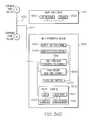
- FIG. 2diagrammatically illustrates a control system 50 for a patient support 52 including many of the aspects of patient support 10 described above.
- the system 50includes one or more function or feature modules 60 , 62 , 64 , 66 , 68 , 70 , 72 , 74 , 76 , 78 operably coupled to patient support 52 and a main controller 54 via one or more communication links 56 , and at least one user module 58 .
- the system 50is configurable to add additional feature or function modules or remove existing feature or function modules as may be required according to a particular use of the patient support, usage setting (i.e. hospital, clinical or home environment), patient type (i.e., immobile, bariatric, ICU, maternity, etc.), or other parameters.
- usage settingi.e. hospital, clinical or home environment
- patient typei.e., immobile, bariatric, ICU, maternity, etc.
- moduledescribes programming logic embodying commands, data, and/or instructions relating to a feature or function of the bed or mattress.
- the programming logicis stored in a memory such as volatile or non-volatile computer memory.
- the memorymay be included in an integrated circuit mounted on a circuit board or substrate, which may be coupled to or embedded in a physical component of the bed or mattress, such as a frame member, lift or articulating mechanism, barrier, mattress ticking, mattress interior component, or the like.
- memory as disclosed here and elsewhere hereinmay take the form of a permanent, temporary or portable storage device, recordable media or other components configured to retain information in digital form for some interval of time, and may include semiconductor-based integrated circuitry (such as flash memory), magnetic storage (such as hard disks), optical storage (such as CD disks), or the like.
- semiconductor-based integrated circuitrysuch as flash memory
- magnetic storagesuch as hard disks
- optical storagesuch as CD disks
- each of the function or feature modules 60 , 62 , 64 , 66 , 68 , 70 , 72 , 74 , 76 , 78is coupled to patient support 52 by electrical and/or mechanical couplings 100 , 102 , 104 , 106 , 108 , 110 , 112 , 114 , 116 , 118 and is coupled to one or more communication links 56 by electrical and/or communication couplings 118 , 120 , 122 , 124 , 126 128 , 130 , 132 , 134 , 136 .
- Mechanical couplingsmay include a mounting bracket, hook, strap, adhesive or other suitable mounting structure or fastener.
- Electrical couplingsmay include insulated wiring, fiber optics, wireless connection, or other suitable data, logic and/or power conduit.
- Communication couplingsmay include a hard-wired or network (wired and/or wireless) connection.
- Communication link(s) 56are coupled to controller 54 via link 138 .
- User module 58may be coupled to controller by links 56 and 140 or link 140 may be directly coupled to controller 54 .
- each function or feature moduleis configured to operate or control one or more predetermined features or functions of the bed or mattress.
- Each moduleincludes a memory such as volatile or non-volatile computer memory, in which a module identifier is stored.
- the module identifier 80 , 82 , 84 , 86 , 88 , 90 , 92 , 94 , 96 , 98 for each moduleis unique relative to all of the other modules coupled to the patient support 52 , so that each module can be independently identified to the system 50 .
- Scale module 60has a memory including programming logic to operate the patient weighing feature of the bed, including accepting user input from user module 58 relating to the “zero” or tare of the scale, or input relating to patient characteristics and the like. User input may be saved in the memory of the scale module 60 .
- Scale module 60may also have a processor, such as an embedded microprocessor, configured to perform certain operations locally at the module.
- Scale module 60includes at least one communication interface for communicating data and/or instructional signals to and from controller 54 and/or user module 58 .
- Alarms module 62includes programming logic and data to operate alarms and/or alerts associated with patient support 52 , including a bed exit alarm triggerable by a patient exiting the bed or approaching a bed exit (e.g.
- Alarms module 62includes programming logic to automatically determine whether a particular patient support as configured includes any functions or features that have an alarm associated with them, and then provides a user interface to enable a caregiver or other user to configure the settings for the alarms and activate and deactivate the alarms.
- Surface module 64includes programming logic and data to operate certain therapeutic features of a patient support, such as turning assistance, maximum inflate, pressure redistribution, and the like.
- Rotation module 66includes programming logic and data to operate a rotation therapy feature of the mattress that is often directed to relieving a patient's respiratory complications.
- Percussion and vibration module 68includes programming logic and data to operate a percussion and vibration therapy feature of the mattress that is also often directed to relieving a patient's respiratory complications.
- Head angle module 70includes programming logic and data to monitor the head of bed angle via signals received from a sensor such as head angle sensor 36 and communicate information to alarms module 62 . Head angle module 70 may also include logic configured to output data indicative of the head of bed angle or an audible or visual indicator thereof on an output device such as may be provided with user module 58 .
- foot angle module 72includes programming logic and data to monitor the foot of bed angle via signals received from a sensor such as foot angle sensor 38 and communicate information to alarms module 62 . Foot angle module 72 may also include logic configured to output data indicative of the foot of bed angle or an audible or visual indicator thereof on an output device such as may be provided with user module 58 .
- Siderail module 74includes programming logic and data to monitor the position of a siderail coupled to the patient support 52 and communicate information to alarms module 62 .
- Siderail module 74may also include logic configured to output data indicative of the siderail status or an audible or visual indicator thereof on an output device such as may be provided with user module 58 .
- Bed exit module 76includes programming logic and data to monitor the position of a patient relative to the bed, via signals received from one or more position sensors coupled to the bed or mattress. Bed exit module 76 communicates information to alarms module 62 . Bed exit module 76 may also include logic configured to output data indicative of the patient position or an audible or visual indicator thereof on an output device such as may be provided with user module 58 .
- Upgrade and/or diagnostics module 78includes programming logic and data to detect when an upgrade, fix, patch, new version or new release of programming logic associated with one of the other modules has become available, and provide audible or visual prompts to a service technician or other authorized person via a user module 58 to perform the upgrade.
- module 78includes software to run diagnostic tests on other modules or components of the bed system, or on the bed system as a whole. Diagnostics software, upgrades, fixes, patches, new versions, new releases, and the like may be transferred or uploaded from a portable device such as a memory stick, which is connected to a communication port of the module 78 , or via another suitable file transfer mechanism.
- Controller 54generally controls and coordinates the operation of the function or feature modules 60 , 62 , 64 , 66 , 68 , 70 , 72 , 74 , 76 , 78 and interaction with the patient support 52 and user module 58 .
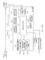
- controller 54includes a communication interface 142 operably coupled to communication link 56 via link 138 , an embedded processor 146 , a memory 144 including programming logic 154 and data 156 , and a communication interface 148 to connect the system 50 to an external network 152 such as a telecommunications network.
- a power supply or power conduit 150may provide power directly or indirectly to controller 54 .
- power supply or conduit 150includes a battery power supply and a connector configured to conduct power received from another source (such as a wall outlet), including power conversion components.
- user module 58 and each of the function or feature modules 60 , 62 , 64 , 66 , 68 , 70 , 72 , 74 , 76 , 78generally includes a power supply or power conduit as well.
- User module 58is configured to enable a person to interact with, operate, configure and/or control the bed system 50 substantially in real time.
- user module 58includes a communication interface 158 operably coupled to communication link 56 via link 140 , an embedded processor 160 , a memory 166 including programming logic 168 , data 170 , and a user module identifier 172 , an input device 162 and an output device 164 .
- Link 140may be directly connected to controller 54 as mentioned above.
- Input device 162includes a touch sensor in the form of touchscreen controls.
- Output device 164includes a liquid-crystal or similar display.
- output device 164includes a high pixel density (e.g. more than 640 ⁇ 480 pixel resolution) and high contrast screen and backlighting to improve visibility from various angles, and the touchscreen 162 is layered above the LCD display.
- input device 162 and output device 164are provided together as one device, such as models manufactured by Okaya Electric Industries Co., Ltd., of Tokyo, Japan or the OSD TN84 LCD and touchscreen.
- input device 162may include a microphone, voice or sound recognition device, keypad, or membrane-style controls, and output device 164 may include a speaker, LEDs, or other like indicators.
- FIG. 3is a high-level timing diagram showing interaction between a user module 180 , a controller 182 and a function or feature module 184 .
- User module 180 , controller 182 and function or feature moduleare components of a patient support system generally configured as described above.
- user module 180receives a signal from a user to activate a bed function or feature.
- the user signalmay be the act of pressing a button, making contact with a touch-sensitive area of a user interface, saying a word recognized by the system, or other action taken by a user.
- User module 180sends a message to the controller 182 identifying the selected bed function or feature and indicating that the selected function or feature is to be activated.
- Controller 182determines the appropriate function module to activate, and sends an “activate function” message including a destination module identifier a function identifier to the designated function module 184 .
- Function module 184sends a message including its function identifier to controller 182 to indicate that the selected function is being activated.
- Controller 182then sends a message to user module 180 including the function identifier to indicate via an output device that the selected function has been activated.
- User module 180then generates the appropriate output.
- the outputis a visual indicator such as a textual message or graphical illustration, but it could alternatively or in addition include an audible indicator or a message sent to a remote device (such as through a nurse call system).
- the graphical illustrationmay include an animated graphic that is designed to simulate motion or movement of the patient support resulting from activation of the selected function, to convey the information to a caregiver or user without using language.
- the controller 182sends a message periodically to the function module 184 to check the progress or status of the selected function, and the function module 184 returns a progress or status message including the function identifier to the controller 182 .
- controller 182Upon receiving the progress or status message from the function module 184 , controller 182 sends a message to user module 180 to provide an indication of the function's status or progress to the user.
- User module 180determines the appropriate indicator to output based on the function identifier and then updates the output device.
- a visual indicatoris updated on a display. For example, a “thermometer”-style graphic may be presented, graphically showing the level of completion of the selected function by filling in the amount completed with a contrasting color or shade. Alternatively or in addition, a textual message such as “In Progress” is displayed.
- user module 180receives a signal from a user to pause the selected bed function or feature.
- the user signalmay be the act of pressing a button, making contact with a touch-sensitive area of a user interface, saying a word recognized by the system, or other action taken by a user.
- User module 180sends a message to the controller 182 indicating that the “pause” feature has been activated by a user.
- Controller 182determines the proper function module to receive the pause signal and sends a message to the function module 184 with instructions to at least temporarily suspend performing the selected function.
- Function module 184returns a message to controller 182 including the function identifier, when the selected function has been paused, and controller 182 sends a message to the user module 180 including the function identifier to give an indication to the user that the selected function is paused.
- User module 180then updates the output device.
- a visual displayis updated. For example, a “pause” button is converted to a “resume” button after the function has been paused by replacing the word “pause” with the word “resume.”
- the color of the buttonchanges from a first color or shade to a second color or shade (such as from red to green).
- controller 182checks the progress or status of the selected function by sending a message including a function identifier to function module 184 . If the selected function has completed its operation, function module 184 returns a “completed” message to controller 182 . Controller 182 then sends a message to user module 180 to instruct it to update its output to indicate that the selected function has completed its operation. User module 180 then updates its output relating to the selected function. For example, the “thermometer” described above may be completely filled in with a contrasting color or shade, or a text message may be updated from “In Progress” to “Completed”.
- a “stop” buttonmay be converted to a “start” button and the color or shade of the button may change from a first color or shade to a second color or shade (i.e. red to green), to visually indicate without using language that the function is ready to be selected again.
- FIG. 4illustrates a portion of a siderail 200 with a user module 204 mounted at an angle, creating a recess 208 from panel 202 .
- Hardpanel controlsare positioned on panel 202 adjacent user module 204 .
- User module 204includes a display 210 supported by a housing 212 .
- Housing 212is constructed of molded plastic or similarly suitable material. Housing 212 is coupled to siderail 200 . Housing 212 may be molded in siderail 200 such that it is an integral part thereof. In other embodiments, such as shown in FIG. 31 , housing 212 may be pivotably coupled to siderail 200 and/or entirely removable from siderail 200 , to be used as a portable or handheld device, for example.
- Display 210includes a first dynamic region 214 , a second dynamic region 216 , a third dynamic region 218 , a fourth dynamic region 220 , touchscreen controls 222 , 224 , 226 , 228 , 230 , 232 , and 234 , and a fifth dynamic region 236 .
- first dynamic region 220is an informational status area indicating the current status of alarms that have been set or enabled.
- Region 220includes a title line (“Active Alarms”). Below the title line, information is displayed if one or more alarms have been set by the caregiver. If no alarms have been activated, the area under the title line appears “blank”. If, as shown, the “out of bed” alarm is activated, a graphical icon indicative of a person standing next to a bed and a textual “out of bed” message is displayed in region 220 .
- Other active alarmsare similarly displayed.
- Second dynamic region 220is an informational status area indicating the current status of the bed.
- a horizontal text lineis provided for each bed status indicator, and for each indicator, a textual description is followed by the current data value for that indicator set off in bold type, contrasting color, or the like.
- the text “Head Angle”is followed by the current actual value of the head of bed angle, displayed in degrees in bold type.
- an external system or networksuch as the NaviCareTM system
- Third dynamic region 218is an informational status area indicating the current surface status or status of available therapies, such as “Rotation,” percussion and vibration (“P&V”), “Opti-Rest,” airflow or “low air loss” (“L.A.L.”), and “Surface” (pressure redistribution).
- a horizontal text lineis provided for each therapy indicator, and for each indicator, a textual description is followed by the current data value for that indicator set off in bold type, contrasting color, or the like. For example, as shown, the text “Rotation” is followed by the current actual status of the rotation therapy (“Off”), displayed in bold type.
- Dynamic region 220includes a graphical representation of a patient positioned on a patient support including a surface, a patient positioned on the surface in the supine position, siderails, and a footboard. Portions of this graphical representation may become animated in response to activation or deactivation of certain functions, as described below.
- the illustration of region 220 shown in FIG. 4represents the bed and patient graphic as displayed when neither the rotation nor the percussion and vibration therapies are active.
- Touchscreen controls 222 , 224 , 226 , 228 , 230are in the form of function tabs positioned along the lower portion of the display and include both a brief text description of the function and a graphical icon illustrative of the function that may be selected.
- Controls 232 , 234are generally used less frequently than controls 222 , 224 , 226 , 228 , 230 and are therefore positioned in another part of the display as shown.
- Each controlcorresponds to a main function or feature of the patient support.
- the usercan quickly switch between functions or features by activating (e.g. by contact) the tab associated with the next desired function or feature.
- the currently active function tabis set off from the others by a contrasting color or shade. In the illustration, the “main menu” tab 222 is lighter in shade than the other tabs because the “main menu” screen is currently displayed.
- the title of the currently active screenis also displayed in textual form at region 236 .
- One or more of hardpanel controls 206may be configured as a “hotkey” or “hotbutton” to cause a change or result on the touchscreen display 204 .
- display 204“times out” (backlighting is turned off) after a period of time.
- a first hardpanel control 206is configured so that when depressed by a user, the backlighting of display 204 is turned back on to “reactivate” a display.
- there are certain bed movement functionsthat are automatically disabled based on certain conditions of the bed. For example, if the siderails are down, the bed may not be able to be moved into “chair” position and rotation therapy may be disabled when any of the siderails are down.
- a second hardpanel control 206is configured to automatically put the bed into the chair position. However, if the siderails are down, a pop-up window is displayed on the display 204 informing the user that the siderails need to be raised before the bed can go into chair position.
- hardpanel controls 206may act as an input device 162 by being configured to send input to processor 160
- output device 164may be configured to display output relating to input received from hardpanel controls 206 and processed by processor 160 .
- display 204may be considered to be a first user module 58 and hardpanel controls 206 may be considered to be second user module 58 , and the modules 204 , 206 may communicate over a link 56 .
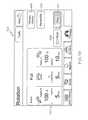
- FIG. 5depicts a user interface 250 for a patient weighing function of a patient support.
- a patient supportmay be configured to weigh a patient positioned thereon.
- the patient supportmay include a weigh frame and a plurality of load beams or cells coupled to the weigh frame.
- a scale module 60is provided.
- Scale module 60receives signals from the load cells and determines a weight therefrom.
- Scale module 60outputs a signal representative of the weight to a controller or network, to be displayed at the user module, transmitted to a remote device, or other purpose.
- Interface 250includes instructional text 252 , a graphical representation of a patient's weight history over time 254 , a non-text communicative element 256 , selective highlighting 258 , a “weigh patient” touchscreen control 260 , a “zero scale” touchscreen control 262 , an “adjust weight” touchscreen control 264 , a “kg/lbs” touchscreen control 266 , and a “view history” touchscreen control 268 for viewing the history of a patient's weight.
- Scale tab 270is set off in contrasting coloring or shading to indicate that it is active as shown.
- the instructional text 252is dynamically updated according to functions or features selected by the user.
- the data area 258is selectively set off with “highlighting,” i.e. a perceptively different coloration or shading, such as bright yellow, to direct the user's attention in a non-textual way to the data presented therein.
- the communicative element 256is shown as a “down arrow” to indicate in a way that does not involve language interpretation that the patient has lost weight during a period of measurement.
- the time period of measurementmay be pre-selected or user-configurable. In the illustrated embodiment, the time period is shown as 24 hours.
- the graphical representation 254is, in the illustration, a line graph displaying the patient's weight over a period of time.
- the weigh patient button 260is set off from the others by selective coloration, i.e. using a perceptively different color or shading to fill in the button.
- the functions and features of the controls 260 , 262 , 264 , 266 , 268are described below.
- Certain protocolsmay require the patient's weight to be obtained before an automated bed function or therapy feature can be activated, such as such as automated pulmonary therapies including rotation and percussion and vibration.
- FIG. 6shows diagrammatically a progression of steps to perform the functions made accessible to the user by the Scale menu 250 , represented by scale block 280 in FIG. 6 .
- Selecting the weigh patient button 260 to obtain a patient's weightis represented by weigh patient block 282 .
- the systemchecks the head angle of the patient support. If the head angle is already less than or equal to 30 degrees, the system proceeds to function block 292 . If the head angle is greater than thirty degrees, the system prompts the user to lower the head angle before proceeding. In some embodiments, an option may be provided to override the head angle check and proceed to weigh the patient even if the head angle is greater than or equal to thirty degrees.
- the bed systemallows the caregiver an amount of time to let go of the bed after selecting the function (i.e., so that contact with the bed does not affect the weight reading).
- a pop-up windowis displayed to inform the user that more accurate results may be obtained if the head section of the bed is lowered below 30 degrees and the deck is in a flat position.
- the systemallows the user time to lower the head section and/or reposition the bed.
- the systemwill not allow the patient weight to be taken until the therapy is paused or stopped.
- the systemwill inform the user by displaying a message and/or graphic on the display and give the user an option to weigh the patient, indicate that the bed is empty, or to set a reminder to be prompted again after a further period of time elapses.
- the systemproceeds to weigh the patient at block 294 .
- the numerical value of the patient's weightis displayed, at which point the user may choose to accept the weight value at block 298 , re-weigh the patient at block 300 or cancel out of the weighing function at block 302 . If the patient's weight is accepted, the weight value is saved into memory and the display is updated at block 304 . If the re-weigh option is selected, the system returns to function block 292 to repeat the process. If the cancel option is selected, the system returns to the main scale block 280 .
- Zeroing the bed scaleprovides a baseline reading against which future weights can be compared.
- instructions for zeroing the scaleare displayed. These instructions may include reminding the user that the bed should not be occupied and that standard linens and other items should be placed on the bed before zeroing.
- the systemallows time to let go of the bed at block 316 , and then the system proceeds to zero the scale at block 320 and update the display with the zeroed information at block 322 .
- the usermay decide to cancel the operation at block 314 , in which case the system returns to scale block 280 .
- Scale module 60also includes programming logic to detect when the patient support is equipped with a pulmonary therapy module, such as percussion and vibration or rotation therapy modules. As these modules add extra weight to the bed, scale module 60 automatically re-calculates the zero weight value if one or more of these modules is present.
- a pulmonary therapy modulesuch as percussion and vibration or rotation therapy modules.
- scale module 60may be configured to automatically adjust the patient's weight value to account for such items.
- Selecting the adjust weight button 264is represented by the adjust weight block 286 .
- the usermay manually adjust the patient's weight by pressing plus or minus buttons 368 , 370 , at function block 324 of FIG. 6 .
- An “automatic compensation” featureis also provided, as shown by region 364 and control 372 of FIG. 7 , at function block 326 of FIG. 6 .
- This featureallows the weigh scale to be customized for individual patient needs.
- the “add/remove items” button 372is selected, the system informs the user that it will weigh or re-weigh the patient before additional items can be added or removed.
- Such itemsmay include therapy devices, IV poles, or other items that an individual patient may normally have with them on the bed and that may affect accurate weighing.
- the systemprompts the user to add or remove those items to/from the bed and weighs the items at block 338 .
- the systemthen informs the user of the new weight including the items added or removed as shown in FIG. 8 .
- the usermay opt to save the weight at block 340 by pressing button 374 in which case the display is updated to inform the user that such items will be discounted from the patient's weight in the future, thereby enabling a caregiver to obtain an accurate weight of the patient without having to add or remove the patient's items from the bed each time.
- the “kg/lbs” function at block 288allows the user to switch between methods of measurement, selecting either kilograms or pounds.
- the “view history” function at block 290allows the user to view a graphical representation of the patient's weight values over time.
- the patient's weight historyis displayed in the form of a bar graph or line graph, similar to FIGS. 28 and 29 , described below, at block 352 .
- FIGS. 9 and 10relate to alarm features of a patient support.
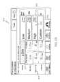
- FIG. 9depicts a main user interface 410 from which a user may select an alarm option to configure.
- Main alarm screen 410is represented by function block 440 of FIG. 10 .
- the alarms function tab 412is offset by a contrasting color or shade from the other function tabs to indicate nontextually that the alarms screen 410 is active.
- alarmsthat may be configured include a bed exit alarm 412 , a head angle alarm 444 , and work flow (illustratively: NaviCareTM) alerts 446 . Additional alarms may be added or may be substituted in place of one of these alarm features by upgrade module 78 .
- Bed exit alarm 412may be set to activate an alarm or alert if the system detects a patient exiting the bed. The alarm may alternatively or in addition activate an alarm if a patient is sitting up in bed, on the edge of the bed, or already out of the bed.
- Head angle alarm 444may be set to detect when the head of bed angle is above or below a certain value or range of values, and generate a notification when the condition is met.
- the alarm screen 410 of FIG. 9includes a brief textual instruction 414 , a first display and input region 416 , a second display and input region 418 , a third display and input region 420 , and a “view history” user control.
- First display and input region 414is set off from the other areas of screen 410 by highlighting or selective coloration, as are regions 418 and 420 .
- Each of regions 416 , 418 , 420includes a data/status region 422 , 424 , 426 in which current data relating to the alarm feature is displayed.
- the word “off”is displayed when the bed exit alarm has not been activated. If the alarm is activated, the word “on” is displayed, and a graphical representation of a person exiting a bed may also be displayed.
- the word “on”is displayed when the head angle alarm has been set or enabled and a graphical depiction is also used to communicate that information without use of words.
- the numerical value of a head angle currently associated with an alarme.g., 30 degrees
- the current status of the work flow alertsi.e., “active” is displayed in text form but also could be depicted graphically.
- Each of regions 414 , 418 , 420also includes a touchscreen control 428 , 430 , 432 , respectively, to modify or change parameters associated with the alarm or in the case of region 426 , to pause or at least temporarily suspend the alerts.
- activation of the “modify” or “change” function 450 , 458results in discrete choices being displayed for selection by the user (blocks 452 , 460 ).
- modify button 430is activated to configure a head of bed angle alarm
- the discrete choicesmay relate to the numerical value or range of values of the angle associated with the alarm, such as 30 degrees, 45 degrees, less than 30 degrees, greater than 30 degrees, greater than 45 degrees, etc.
- modify button 428is activated to configure a bed exit alarm, the discrete choices may include out of bed, edge of bed, sitting up in bed, and the like.
- the NaviCareTM system and other similar systemsconnect and monitor powered beds, patient supports and surfaces by sending bed and surface data to network applications for caregivers to view and receive alerts at a nurse's station.
- the work flow alerts feature 420 of the patient supportenables a caregiver or other user to pause or at least temporarily suspend the work flow alerts directly at the bedside of the patient.
- the useractivates the work flow alerts by pressing alerts button 432 , then status information from the patient support will be communicated to the nurse's station over a network through the work flow or bed status system. For instance, if the head of bed angle is lowered below 30 degrees, an alert may be generated and sent to the nurse's station.
- a caregivermay be able to temporarily suspend the sending of these types of messages to a nurse's station, for example while a patient is receiving a treatment, diagnostic test, is exiting the bed for therapy or other reasons, or the like.
- Pressing the pause alerts button 432may thereby enable a caregiver to eliminate unnecessary nurse calls due to changes in the bed's status that are part of the patient's normal routine, for example.
- the caregiverdoes not need to exit the patient's room to turn off or disable the alerts at a nurse's station. Instead, the caregiver can pause the alerts right from the patient's bedside.
- Alarms module 62includes programming logic to automatically detect whether the bed position, status or conditions are appropriate before activating a selected alarm. For example, if the actual head of bed angle is lower than about 30 degrees, alarms module 62 will prompt the user to raise the head section of the bed before the head of bed angle alarm can be set. Alarms module 62 continues to monitor the bed position, status and conditions after an alarm is set and/or while another bed function, feature or therapy is in progress. For instance, an automated rotation therapy may be stopped or at least temporarily suspended if the head of bed angle is above about 40 degrees and/or the foot of bed angle is below about 30 degrees.
- the systemwill display a pop-up window prompting the user to decide whether to continue and may at least temporarily pause the percussion and vibration therapy.
- the systemwill display a pop-up window prompting the user to decide whether to start the percussion and vibration therapy and may at least temporarily pause the rotation therapy.
- alarms module 62will issue pop-up windows containing alert messages and/or graphics to communicate with the user.
- Alarms module 62includes programming logic configured to color-code messages according to severity or type of message. For example, a message that is printed in a first color (such as blue) or presented against a first background color (e.g. blue) may be primarily informational in nature. A message that is displayed in a second color (such as yellow) or displayed against a second (e.g. yellow) background color may indicate a possible safety issue or indicate a possible bed limitation or unsafe condition relating to the patient support. A message that is printed in a third color (such as orange) or displayed against a third (e.g. orange) background color may indicate a safety issue relating to the patient.
- a first colorsuch as blue
- a first background colore.g. blue
- a message that is displayed in a second color (such as yellow) or displayed against a second (e.g. yellow) background colormay indicate a possible safety issue or indicate a possible
- Steps associated with the view history button 434are depicted in FIG. 10 beginning with block 448 .
- Examples of alarm history reportsare shown in FIGS. 28-30 .
- the reportsmay be configured by the user at the select view block 468 , in which the date range, time of day, and duration scales may be adjusted (i.e. the “x” axis and “y” axis).
- the patient's history datais displayed according to the selected view criteria at block 470 in the form of a bar graph or line graph.
- the usermay modify the view parameters at block 472 , at which point the system displays the choices of parameters that can be modified at block 474 , urges the user to make a selection at block 476 and updates the display according to the modified selections at block 478 .
- FIG. 11depicts a main screen 490 for configuring surfaces related features and functions of a patient support.
- function tab 492is offset by contrasting color or shading to indicate nonverbally that the surfaces screen is active.
- a brief instructional text 494is provided, main function or feature areas or control regions 496 , 498 , 500 , 502 are offset from each other by selective coloration or highlighting, and touchscreen controls 504 , 506 , 508 , 510 , 512 are provided in each control region. Text and graphical icons are provided to quickly direct the user's attention to the desired function.
- FIG. 12Functions configurable by surface screen 490 are shown in FIG. 12 and include maximum inflation 522 , opti-rest 524 , turning assistance—patient right 526 , turning assistance—patient left 528 , seat deflate 530 , reminder 532 and low air loss 534 .
- a graphical representation of a person positioned on a maximum-inflated surfaceis associated with the max-inflate control region 496 and a downwardly pointing arrow above the seat section is associated with the seat deflate feature 510 .
- the automated max-inflate module 522may be activated to help facilitate changing a patient's position on the support surface or transfer of the patient to another surface (such as a stretcher or operating room table).
- the featureis configured with reference to the patient, i.e., “patient right” and “patient left”.
- the automated turning assistance modules 526 , 528may help facilitate linen changes or wound inspection by facilitating rotation of a patient onto his or her side. Graphical representations aid the caregiver in quickly determining which of the controls 506 , 508 is associated with each side of the patient. The clear and succinct indication of the point of reference may help reduce potential confusion and resulting mistakes.
- Selective colorationmay also be used in the user controls.
- the “start opti-rest” control 512is filled in with a first suggestive color, i.e., green for “go”. If the button 512 is activated, the text changes to “stop opti-rest” and the filling changes to a second suggestive color, i.e. red for “stop”.
- activation of the “opti-rest” module 524causes the patient support surface to automatically repeat a cycle of varying the pressure underneath a patient's chest, seat and thighs, producing a wave-like motion.
- seat-deflate module 530includes programming logic to selectively deflate the seat section of the patient support surface, to help facilitate side ingress and egress or for other reasons.
- Low air loss module 534generally includes programming logic to provide air circulation underneath a patient positioned on the patient support.
- the “remind me” button 514enables configuration of a caregiver reminder feature of the patient support, wherein a caregiver may schedule the patient support system to issue a reminder to the caregiver to activate or deactivate a therapy or other bed or mattress function or feature.
- a remindermay be configured to remind the user to repeat a therapy function (such as weighting a patient, performing turning assistance, or performing an automated pulmonary therapy) after a period of time that may be pre-defined or selected on the fly by the user, or to remind the user to repeat, start or stop a function, feature or therapy before or after a certain amount of time has elapsed (as may be desirable in the case of percussion and vibration therapy).
- a therapy functionsuch as weighting a patient, performing turning assistance, or performing an automated pulmonary therapy
- Such a remindermay be sent by the bed through a network to a wireless communication device (e.g., PDA, Vocera badge, wireless telephone handset or the like, carryable by a caregiver, as described in U.S. Patent Application Publication No. 2006-0049936 A1, incorporated herein by this reference).
- a wireless communication devicee.g., PDA, Vocera badge, wireless telephone handset or the like, carryable by a caregiver, as described in U.S. Patent Application Publication No. 2006-0049936 A1, incorporated herein by this reference.
- FIG. 13shows a screen 540 for configuring a reminder to the caregiver if the turning assistance operation has been stopped for a defined period of time. Such a reminder may be desirable to remind the caregiver that it is now time to activate turning assistance again.
- a brief textual instruction 550 relating to the active function 544is provided and may change as the active function changes.
- Screen 540shows locked-out functions, i.e., functions that are not currently available to be configured, in reverse highlighting or “grayed out” mode 546 .
- the remind me button 544is activated and is shown filled in with a contrasting color in comparison to FIG. 11 .
- a pop-up area 548includes “one touch” selection buttons that allow the user to quickly select the period of time after which the reminder should be generated by only requiring a single action of the user: pressing or contacting one of the available buttons. Pressing in the grayed out area outside of region 548 does not result in any action or response by the patient support system.
- only one of the selection buttons in region 548can be activated at a time.
- the screen 540is thereby designed to reduce the risk of error due to confusion or unintentional or accidental button pressing by the user.
- Remindersmay be set in a like manner for rotation, percussion and vibration, turning assistance, and/or other therapies, features or functions of the patient support.
- a visual display of the time remaining until the next remindermay be presented, as shown by countdown area 672 of FIG. 16 . If the reminder feature is in progress, and a user then starts a therapy, then the reminder countdown will automatically be stopped while the therapy is in progress, and the clock will reset and restart the countdown after the therapy is stopped or completed. When the reminder clock finishes its countdown and issues the reminder, the user may have the option to reset the reminder clock.
- a usercan select a discrete amount of time to elapse after completion of a therapy after which a reminder will issue.
- the available reminder time choicesmay include 10, 20, 30 and 40 minutes.
- the reminder time choicesmay include 1, 2, 4, 5, and 6 minutes.
- the reminder time choicesmay include 30, 60, 90, and 120 minutes.
- FIGS. 14 and 15relate to operation of therapy functions of a patient support.
- FIG. 14illustrates a user interface for selecting a therapy function
- FIG. 15is a diagram of steps performed in the operation of the functions.
- Main therapy screen 560is similar to other main screens described above, in that the therapy function tab 562 is displayed in a contrasting color relative to the other function tabs to visually indicate that the therapy screen is active, and additionally, the “Therapy” title appears at the top of the screen.
- Screen 560includes a first control region 564 and a second control region 566 . Additional control regions may be added in area 584 or control regions 564 , 566 may be replaced by other control regions, as new or upgraded therapies are loaded or added to the system, for example by upgrade module 78 . Each of the control regions is set off from the others by selective highlighting, shading or coloration for ease of use.
- Control region 564includes textual and graphical elements to communicate to the user that the region is associated with rotation therapy.
- Textual elementsinclude the button 568 titled “rotation”.
- Graphical elementsinclude an arrow 572 extending laterally across a graphical depiction of a patient 574 positioned on a patient support. The tail of arrow 572 is curved or arced to suggest movement in the direction of the arrow head. When the patient is rotated in the opposite direction, the direction of the curved arrow is reversed.
- Control region 566includes the function description “percussion and vibration” label on the user control 570 and graphical elements including a patient body 576 supinely positioned on a support surface 582 , siderails 578 in the “up” position, and percussion and vibration elements 580 located on the surface 582 adjacent the shoulders and hands of the body 576 .
- elements 580have the appearance of concentric circular ripples.
- Buttons 568 , 570are touchscreen controls in the illustrated embodiment.
- Button 568is represented in FIG. 15 as rotation function block 592 .
- a main rotation screen 640such as shown in FIG. 16 , is displayed.
- Screen 640provides options to the user including selecting or configuring rotation settings 596 , configuring or activating a reminder 598 , and viewing rotation history 600 .
- Control region 644includes a plurality of touchscreen controls 650 , 652 , 654 , 656 , 658 , 662 . These controls are designed as “one touch” controls as described above, such that after a control is selected for configuring, only one touch is required by the caregiver to select the appropriate value for the control.
- buttons 684are indicated by selective coloration as being selected. Selection of button 684 results in pop-up area 688 being displayed. The user may select only one of the available buttons 690 at a time. Once a button 690 is selected, the pop-up disappears and the selected button value is displayed at button 684 (i.e., if the user selects “80%”, the value “80%” would replace the “100%” previously displayed at button 684 ).
- buttons on the user moduleeffectively act as both an input device and output device, because the new value selected by the user is subsequently displayed on the selection button itself.
- This type of “one touch” rotation selectionallows for faster adjustments by a caregiver than prior art systems in which a caregiver must press and hold a button (pr press the button multiple times) while the rotation amount scrolls numerically up or down, or in which a dial is turned or lever moved or a graphical icon is moved via touching and dragging from the prior setting to the new setting.
- a usermay select a preset condition via touchscreen control 650 .
- the preset conditionsinclude predefined rotation settings, for example: “minimum” at 8 cycles per hour (cyc/hr), 50% turn; “moderate” at 10 cyc/hr, 70% turn; or “full” at 12 cyc/hr, 100% turn.
- the usermay select “custom” via control 650 , in which case buttons 652 , 654 , 656 , 658 , 662 become enabled, thereby allowing the user to more specifically configure the rotation settings.
- Turn percentage buttons 652 , 654enable the user to select an amount of turn to the right or left.
- Right pause 656 , center pause 658 , and left pause 662enable the user to select an mount of time to pause or hold the patient in the right side-lying, centered, and left side-lying positions before proceeding to the next position.
- a graphical indicatorsuch as triangle 674 , positioned on a control button, may be used to indicate that the element is configurable. For example, pressing a button that has an indicator 674 results in a pop-up display of selectable choices. If a “preset” configuration is selected, the “custom” controls are disabled or grayed out.
- Region 644 of FIG. 16also includes graphic elements 646 , 648 , which are displayed from the patient's reference point.
- element 646appears tilted toward the left side of the user interface from the perspective of a person viewing the screen 640 , but corresponds to how a patient rotated to the patient's right side would appear from the perspective of a caregiver located at the foot end of the bed.
- Element 648is similarly configured to represent rotation to the patient's left side.
- Region 644also includes a numerical value 660 , which represents the number of cycles per hour that correspond to the number of minutes of rotation selected by the caregiver at button 658 .
- the numerical value 660is automatically calculated and updated.
- Screen 640also includes a textual instruction 642 that is updated as the user selects different functions on the screen, a back button 664 to return the user to the previously selected function, a therapy history button 666 corresponding to function block 600 to enable the user to view a history of rotation therapy applied to the patient, and a reminder button 668 corresponding to function block 598 of FIG. 15 .
- a “start” button 670which, when activated, starts the operation of the rotation therapy according to the user selected parameters. Prior to activation, button 670 is filled in with a first suggestive color (e.g., green for “go”). When the rotation therapy is in progress, button 670 converts to a “stop” button filled in with a second suggestive color (e.g., red for “stop”), as shown in FIG. 19 .
- the systemautomatically checks whether the siderails are up or down (e.g., via siderail module 74 ) at block 602 . If any of the siderails are down, the user will be prompted via an appropriate message on the display screen to raise them before rotation therapy can start. The system also automatically checks whether the seat deflate feature is active, at function block 603 . If seat deflate is active, the user will be prompted to deactivate the seat deflate feature before rotation therapy can start.
- Rotation “training”may be used to gradually introduce the patient to the rotation therapy. In the illustrated embodiment, rotation will begin at half the maximum turn degree and gradually increase over time to acclimate the patient.
- rotation therapymay be at least temporarily suspended or paused when any siderail is lowered, when head of bed angle is raised higher than about 40 degrees, when foot of bead angle is lowered more than about 30 degrees, when the patient support is in or moving into or attempted to be moved into the chair position, if percussion and vibration, max-inflate, or turning assistance is activated, or if CPR is activated, or for other reasons.
- Rotation therapyis started as indicated at block 604 .
- the user displayis updated as shown in FIG. 19 once the rotation therapy is in progress.
- Rotation status display screen 700displays the current rotation settings in region 702 , which is set off from the rest of screen 700 by highlighting, shading or coloration, and button 704 is modified to enable the user to stop the therapy as described above.
- FIG. 20illustrates a main menu screen as updated at block 606 , while rotation therapy is in operation.
- Screen 710is similar to the main menu screens previously described, except that portions of the patient and bed graphic 744 are animated to simulate rotational movement of the support surface and patient that occurs when rotation therapy is in operation.
- a thermometer-style status bar 712indicates the amount of progress completed for the rotation therapy. Status bar 712 is set off from other parts of the screen 710 by selective coloration, highlighting or shading 740 .
- a “pause” button 742is provided to allow the user to at least temporarily suspend the therapy in progress.
- the buttonis generally made conspicuous (e.g., larger size, centrally located) for easy access by the caregiver.
- Graphic 744includes animated graphical elements that dynamically change the display to simulate rotation of the surface and patient when rotation therapy is activated.
- the surface 724is shown as rising on one side of the patient thereby “elevating” the corresponding shoulder 716 and leg 720 of the patient, in the graphical depiction.
- the graphical depiction of the surface and patientcontinue to dynamically change in an animated fashion as a side of the support surface and patient graphical elements rises and rotates. For instance, the patient's head 714 , arm 718 and leg 722 become animated to indicate rotation in the reverse direction.
- Arrow graphical element 736is also animated to indicate motion in the direction of the arrow head 738 .
- Coloring or shading of the arrow bodyis configured to convey a sense of motion in the direction of the arrow head 738 as well.
- the arrow tailis filled with a lighter shade and the arrow is gradually darkened toward the arrow head 738 .
- While in rotation therapythe user may pause the therapy by pressing button 742 .
- another bed functionmay be activated, such as another therapy, the weigh scale, or other function or feature of the bed or mattress.
- pause button 742is activated, the animation of graphical element 744 also pauses and “moving arrow” 736 , 738 is not displayed during the pause, as shown in FIG. 21 .
- screen 750the status thermometer 712 is shown in reverse highlighting or “grayed out” mode 754 when the therapy is paused. A textual indicator that the therapy is “paused” is also provided.
- button 752is converted from a “pause” button to a “resume” button.
- the user interfacemay display a visual message such as “In Progress” to indicate that a therapy is in progress.
- the systemwill also automatically temporarily pause an in-progress rotation therapy if the user activates a percussion and vibration therapy while rotation therapy is running, and then will resume the rotation therapy so that both rotation and percussion and vibration therapies can be in operation at the same time. If a percussion and vibration therapy is in progress, however, a new rotation therapy may be started without pausing the percussion and vibration therapy.
- multiple therapiessuch as rotation, percussion and vibration, and surface therapies, may be requested. When multiple therapies are in operation at the same time, each therapy type may be paused or stopped without affecting the other ongoing therapies.
- FIGS. 22-26relate to an automated percussion and vibration therapy of a patient support
- FIG. 15illustrates steps performed in configuring a percussion and vibration therapy.
- Screen 760 of FIG. 22is displayed when a percussion and vibration therapy is not already in progress.
- the usermay configure the settings for percussion and vibration therapy via controls 768 , 770 , 772 , 774 , 776 , 778 , 789 , 784 , 786 , 788 , 792 .
- These controlsare “one touch” controls as shown in FIGS. 23 and 24 and described above with reference to the rotation therapy configuration screens.
- an optionis presented to the user to select a predetermined percussion and vibration therapy setting using touchscreen control 768 .
- Activating control 768enables the user to select from a plurality of discrete preset choices, such as “low” at 4 bps (beats per second) and duration of 10 minutes; “medium” at 5 bps and 10 minutes duration; “high” at 5 bps and 15 minutes duration.
- “custom”is selected at control 768 , in which case touchscreen controls 770 , 776 , 772 , 778 , 774 , 780 become enabled. If “preset” configuration is selected, the “custom” controls are disabled or grayed out.
- Intensitymay be customized for percussion and vibration by using controls 770 , 776 .
- Discrete choices for each control 770 , 776such as “low”, “medium”, and “high” are displayed and one of the choices may be selected by the user for each control 770 , 776 .
- the discrete choicesinclude 1 to 5 beats per second, for example.
- the discrete choicesinclude 5 to 25 beats per second, in 5 bps increments, for example.
- duration buttons 774 , 780the choices include a range of values between and including 1 to 30 minutes, for example. In one embodiment, a minimum duration of about 3 minutes is required for therapy history statistics to be captured.
- Patient position for percussion and vibration therapyis selectable by activating modify control 784 .
- Discrete choices for position control 782include patient's right side 816 , patient's left side 820 , centered 818 , or rotation 814 , as shown in FIG. 24 . If right side 816 or left side 820 is selected, then the amount of turning (i.e. percentage) is selected for automated turning assistance to that side. If rotation is selected, then the rotation settings are configured as described above with reference to FIG. 16 . If the user selects OK at control 830 , then the position selected is displayed at control 782 of FIG. 22 .
- the usermay initiate operation of the therapy via control 788 .
- the patient support systemPrior to starting the percussion and vibration therapy, the patient support system checks the siderails at function block 620 and checks the head of bed angle at function block 622 . If one or more of the siderails is down or the head of bed angle is above an acceptable range (e.g. above 40 degrees), the system prompts the user via an appropriate message on the display screen to make the appropriate adjustments to the patient support before the therapy can be started.
- an acceptable rangee.g. above 40 degrees
- the user interface displayis updated at function block 626 to activate the animated features of the graphical user interface, as shown in FIG. 26 .
- the portions of graphical element 842 of screen 840become animated to simulate the percussion and vibration motion experienced by the patient positioned on the patient support. This is accomplished by providing animated elements 844 , 846 , 848 , 850 . These elements are “active” concentric circular ripples that appear as though they are vibrating through the use of animation.
- a thermometer-like status bar 852is also provided in a highlighted region 854 to communicate the status of the therapy to the user.
- a pause button 856is also provided and operates in like fashion to similar buttons described above.
- rotation therapy animationsi.e., “turning” patient and “moving” arrow
- percussion and vibration animationsi.e., “vibrating” ripples
- FIG. 27illustrates a patient history reports screen 860 , which gives the user access to historical data about the patient, the patient support, and features, functions, and therapies provided by the patient support.
- Available historical dataincludes data relating to the patient's weight 872 , the length of time the patient support is in the chair position 874 , the history of vibration therapy performed 876 , the history of active bed exit alarms 878 , the history of rotation therapy performed 880 , the history of “opti-rest” or pressure redistribution or other surface therapies performed 882 , the history of active head of bed angle alarms 886 , and the history of percussion and vibration therapy performed 888 .
- a graphical icon 884sets off the alarm history features from the other available options for easy identification by the user as indicated by legend 870 .
- a graphical element 864is used in conjunction with the textual screen title 862 to orient the user with the screen.
- FIGS. 28-30illustrate historical data graphs for bed exit alarm history and head of bed angle history as described above. Selective coloration is used to indicate to the user the time periods of active alarms, as shown.
- the relatively darker areas of the graph 904 , 908indicate time periods in which the bed exit alarm is enabled or set, while the relative lighter shaded areas 892 indicate time periods in which the bed exit alarm is turned off.
- the darker shaded areas 936indicate time periods when the head of bed angle alarm is enabled or set.
- such historical informationmay be provided in a tabular form or another graphical form, or other suitable format as may be considered desirable by the user.
- the usermay customize the “x” and “y” axes of the graphs of FIGS. 28-30 .
- the “y” axis 894 , 924indicates the time period during the day and may be extended up to 24 hours or shortened to a shorter period within the day.
- the “x” axis 896 , 926shows the days in the date range monitored.
- the “duration” 898 , 928is an automatically calculated value representing the amount of time the particular alarm was enabled or set for each day shown in the graph. For example, referring to FIG. 28 , on Oct. 11, 2006 the bed exit alarm was set for a total of 12 hours and 19 minutes on that day.
- the duration featureenables a caregiver to quickly spot days that may have been out of the ordinary in terms of the duration of alarms set.
- the caregivercan then go directly to the bed exit alarm configuration screen (e.g. FIG. 9 ) to reconfigure the alarm settings, via control 900 .
- touchscreen control 930enables the user to change the current view, while control 932 displays the current view (e.g., times and durations of monitoring the head of bed angle and the head of bed angle was above 30 degrees).
- Pressing the modify view button 930presents discrete choices 956 , such as above 30 degrees, above 45 degrees, and the like, at control 954 .
- Control 954also provides the user with an option to view the alarm history, i.e., the history of occurrences of the head of bed angle actually having been triggered or activated by the head of bed angle going below the preset alarm condition. An alarm history graphical report representing the history of activated alarms may then be viewed.
- FIG. 31illustrates an embodiment of a patient support 970 including multiple user modules 1016 , 1018 and multiple user module mounting regions 1002 , 1004 , 1006 , 1008 , 1012 .
- Patient support 970has a head end 972 and a foot end 974 , a base 976 , frame 978 supported above the base 976 by a lift mechanism 982 , a deck 980 , wheels or casters 984 , 986 , a mattress 988 , a head of bed angle sensor 990 coupled to mattress 988 , and perimeter barriers 992 , 994 , 996 , 998 , 1000 , 1002 .
- User module docking regions 1004 , 1006 , 1008 , 1010 , 1012are provided in the barriers as shown.
- a user module mounting bracketsuch as element 1014 may be provided to fixedly, pivotably, or releasably secure a user module within or to a mounting region.
- User interfaces 1016 , 1018are generally configured with graphical, textual, and touchscreen elements as described above.
- any one of the multiple user modulesmay be used to operate the patient support or features thereof.
- Each of the user interfaces of the multiple user modulesare synchronized to provide the same display and data substantially at the same time.
- the systemtreats each button activation in sequential order. This makes the workflow “interruptible” by any user module.
- Two userscan also work together to complete an operation such as weighing a patient. For example, a first user presses the scale control of a user interface of a first user module to activate the patient weighing feature. The first user then holds IV lines or other items or equipment away from the bed surface, while a second user presses the “weigh patient” button and reads or records the patient's weight.
- FIG. 32is a simplified block diagram of one embodiment of a multiple user module system including a patient support 1030 , a controller 1038 , and a plurality of user modules 1032 , 1034 , 1036 , which are operably coupled to patient support by mechanical and/or electrical links 1042 , 1044 , 1046 and are electrically coupled controller 1038 via links 1048 , 1050 , 1052 , respectively.
- Controller 1038includes synchronization logic 1040 stored in a memory and executable by a processor to synchronize the activities and the displays of the multiple user modules so that when an action is taken at one user module, the displays of the other user modules are automatically updated.
- Controller 1038receives input signals from a first user module 1032 , a second user module 1034 , and a third user module 1036 , or any number of user modules. Such signals are time-stamped and controller 1038 applies synchronization logic to process the signals in sequential order and update the output to the displays as needed.
- FIG. 33is a simplified block diagram of another embodiment of a multiple user interface system including a patient support 1060 , a network 1062 , a plurality of user modules 1064 , 1066 , 1068 , and a controller 1070 .
- Each of patient support 1060 , controller 1070 , and user modules 1064 , 1066 , 1068are operably coupled to communication network 1062 by communication links 1072 , 1074 , 1076 , 1078 , 1080 .
- the user modulesreceive input signals from the user via a touchscreen control or other input device.
- the input signalsare converted by programming logic stored at the module to a network-readable format and sent over the network 1062 .
- the other user modules and the controller 1070receive the network message.
- the other user modulesacknowledge the message and update their displays as needed.
- Controller 1070monitors the network, forwards the message to the appropriate function module 1082 , 1084 to perform the requested bed or mattress function, checks for acknowledgement messages confirming that the function has been performed, converts acknowledgement messages to network-readable messages and sends the acknowledgement messages to the user modules over the network.
- the user moduleseach receive the acknowledgment messages and update their displays as appropriate.
- the user modulesmay each send a reply message to the controller so that the controller knows that each user module has been updated.
- the network 1062may include peer-to-peer connections (for example, as between the user modules and the controller or between the function modules and the controller), master/slave connections, or a combination of peer-to-peer and master-slave connections.
- An example of a master/slave configurationis a function module that receives input that originates from an analog device, such as a load cell, angle sensor, pressure sensor, position sensor, or the like.
- a scale module for obtaining patient weightis connected to load cell modules in a master/slave configuration where the load cell modules are the “slaves” because they only communicate with the scale function module.
- FIG. 34is a bottom-end perspective view of an exemplary user module 1090 .
- User module 1090includes a housing 1092 having a top end 1096 and a bottom end 1098 .
- a data/communication port 1100is located in the bottom end 1098 (although it could be located elsewhere on the user module).
- Data/communication port 1100may include a standardized electrical connector 1102 , such as a Universal Serial Bus (USB) port, memory card slot, memory stick reader, or similar connector.
- Connector 1102enables a peripheral device, storage media, remote computer, or other computing devices, such as portable memory card readers, laptops, or printers, to be connected to the user module 1090 at port 1100 .
- USBUniversal Serial Bus
- a memory cardsuch as SD, MMC, CompactFlash, or the like
- User module 1090includes programming logic configured to recognize the existence of a connection at connector 1102 , indicate the connection on the display, and display prompts to enable a service technician or other authorized person to perform functions at the user module relating to the connected device or media. For example, software fixes, upgrades or new releases to the user module or modules may be performed, or software fixes, upgrades, or new releases for a bed or mattress function module may be received at the port 1100 and then transmitted to the appropriate function module by the user module over a bed or mattress network. In addition, if a new user module or function module is added to the bed or mattress system, or an existing module is being replaced, software configured for the new module may be uploaded to the system via port 1100 .
- FIG. 35illustrates an embodiment of a patient support apparatus 1200 , which is a powered hospital bed configurable to assume a plurality of different positions, including a horizontal or flat position (shown), a chair position, positions intermediate the horizontal and chair positions, Trendelenburg and reverse Trendelenburg and hi-low positions.
- Bed 1200has a bed frame including a base 1202 , an intermediate frame 1204 , a weigh frame 1206 and a deck 1208 .
- Deck 1208includes an articulatable head section and an articulatable foot section.
- Intermediate frame 1204is supported above base 1202 by lift or articulation arms 1210 , 121 , and thereby has an adjustable height.
- Frame 1204has a retractable and extendable foot section 1238 , which includes an automated mechanism for shortening and lengthening the foot section 1238 .
- the length of foot section 1238may be adjustable to customize the length of the sleep surface for a patient. Alternatively or in addition, the length may be automatically adjusted to facilitate moving bed 1200 into and out of a chair position, i.e., automatically shortened as bed 1200 moves into a chair position and automatically lengthened as bed 1200 moves from the chair position into one of the bed positions.
- a support surface 1230is supported by deck 1208 .
- surface 1230includes a plurality of inflatable bladders, however, surface 1230 may include other types of support members such as foam, three-dimensional material, and the like, and may include additional elements to be configured as a treatment surface (e.g. including pressure reduction and/or low airloss features) or therapy surface (e.g. including pulmonary features such as rotation or percussion and vibration). Additionally, surface 1230 may be usable with patients weighing up to or over 500 pounds. Further, surface 1230 generally has resilient, retractable/extendable, or length-adjustable members (such as specially cut foam or deflatable bladders) in the foot section to cooperate with the length-adjustable foot section 1238 .
- resilient, retractable/extendable, or length-adjustable memberssuch as specially cut foam or deflatable bladders
- Head end siderails 1264 , 1266are positioned adjacent the lateral sides of the head section. Intermediate siderails 1268 , 170 are also positioned adjacent the lateral sides of the bed and are longitudinally spaced from head end siderails 1264 , 1266 as shown. A removable headboard 1218 and removable footboard 1232 are positioned adjacent the head end and foot end, respectively, of bed 1200 .
- Bed 1200also includes one or more transport handles 1214 , which are configured to enable bed 1200 to be maneuvered or transported manually or with the assistance of a powered transport system 1248 , such as the IntelliDrive® transport system sold by the Hill-Rom Company.
- a powered transport system 1248such as the IntelliDrive® transport system sold by the Hill-Rom Company.
- Each of siderails 1264 , 1266 , 1268 , 1270includes an outer panel facing outwardly away from the surface 1230 and an inner panel facing inwardly toward the surface 1230 , wherein the inner panel may generally be configured to be accessible to a person positioned on the surface 1230 and the outer panel may be generally configured to be accessible to a user or caregiver not located on the surface 1230 .
- a head of bed angle indicator 1216provides a visual cue indicative of the current angle of the head section of bed 1200 .
- Indicator 1216is located on an outer panel of head section siderail 1266 in the illustrated embodiment.
- a Trendelenburg angle indicator 1220provides a visual cue indicative of the current Trendelenburg angle of the bed 1200 .
- Indicator 1220is located on an outer panel of intermediate siderail 1270 in the illustrated embodiment.
- a speaker 1222is located on the inner panel of head end siderail 1264 in the illustrated embodiment. Speaker 1222 is operably connected to a nurse call system and/or to a patient entertainment system.
- a patient control panel 1228is located on the inner panel of intermediate siderail 1268 in the illustrated embodiment and includes buttons, switches, or controls to enable the patient to adjust a position, function or feature of the bed 1200 , such as to raise the head section or call a nurse.
- Outer panel of head end siderail 1266also includes a bed hi-low control 1258 , which includes buttons or switches to raise and lower the frame 1204 relative to the base 1202 .
- Outer panel of intermediate siderail 1270also includes siderail controls 1224 and a graphical user interface or graphical caregiver interface (GCI) 1226 .
- siderail controls 1224include hardpanel electromechanical switches while GCI 1226 includes a dynamic display with touchscreen controls as described above.
- GCI 1226is may be pivotably coupled to siderail 1270 as previously described.
- the inner and outer panels of head end siderails 1264 , 1266are substantially identical and are provided with the same features and functions
- the inner and outer panels of intermediate siderails 1268 , 1270are substantially identical and are provided with the same features and functions, so that a patient or caregiver can access the controls from either side of the bed; however, this need not be the case.
- bed 1200may include equipment electrical sockets 1234 , one or more bumpers or wall guards 1236 , drainage bag holders 1240 , one or more accessory outlets 1242 , casters 1244 (single or dual wheel), foot pedal 1246 , emergency Trend or CPR lever 1246 , brake and steering system 1252 , siderail release mechanisms 1254 (on each siderail), one or more IV poles 1256 , and/or patient helper 1260 , which includes a trapeze 1262 . Additional details of the above-described features and functions of bed 1200 are further described in U.S. Provisional Patent Application Ser. No. 60/982,300, filed Oct. 24, 2007, incorporated herein by reference.
- Electrical system 1300includes base frame components and circuitry 1302 , intermediate frame components and circuitry 1304 , weigh frame components and circuitry 1306 , left and right head siderail components and circuitry 1308 , 1310 , and left and right intermediate siderail components and circuitry 1312 , 1314 .
- Base frame components and circuitry 1302are coupled to base frame 1202
- intermediate frame components and circuitry 1304are coupled to intermediate frame 1204
- weigh frame components and circuitry 1306are coupled to weigh frame 1206
- left and right head siderail components and circuitry 1308 , 1310are coupled to left and right head siderails 1264 , 1266 , respectively
- left and right intermediate siderail components and circuitry 1312 , 1314are coupled to left and right intermediate siderails 1268 , 1270 , respectively.
- the electrical components and circuitrymay be embedded in, adhered to, or otherwise mounted in or fastened to a physical component or member of the corresponding frame or barrier member in such a way as to be permanently fixed relative to the frame or barrier member, or may be removable or replaceable relative to the frame or barrier member.
- Base frame components and circuitry 1302includes a power control module 1316 , which is electrically connected to a plurality of printed circuit board assemblies and cables, including air source/blower assembly 1318 , transformer assembly 1320 , battery assembly 1322 , manifold and pump assembly 1324 , foot hi-low position sensor assembly 1326 , head hi-low position sensor assembly 1328 , brake safety switch assembly 1330 , scale assembly 1332 , CPR switch assembly 1334 , emergency trend switch assembly 1336 , night light assembly 1338 , accessory A/C plug and cable assembly 1340 , and electrical line cord assembly 1342 .
- air source/blower assembly 1318a plurality of printed circuit board assemblies and cables, including air source/blower assembly 1318 , transformer assembly 1320 , battery assembly 1322 , manifold and pump assembly 1324 , foot hi-low position sensor assembly 1326 , head hi-low position sensor assembly 1328 , brake safety switch assembly 1330 , scale assembly 1332 , CPR switch assembly 1334 , emergency trend switch assembly 1336
- Intermediate frame components and circuitry 1304includes a plurality of printed circuit board assemblies and cables including a patient control pendant assembly 1344 , a plurality of load beam assemblies (four, in the illustrated embodiment) 1346 , and sidecomm, nurse call, entertainment, and lighting assemblies 1348 .
- the sidecomm assembly 1348is coupled to a becon module 1352 and the nurse call assembly is coupled to a network connection 1350 (such as Ethernet) to communicate with an external network.
- Weigh frame components and circuitry 1306includes a plurality of printed circuit board assemblies and cables including a weigh frame junction assembly 1354 , siderail detection switch assemblies 1356 (one for each siderail, illustratively), knee position sensor assembly 1358 , head position sensor assembly 1360 and foot position sensors 1362 .
- Left and right head siderail components and circuitry 1308 , 1310include, respectively, a plurality of printed circuit board assemblies and cables including speaker assemblies 1364 , 1368 and bed up/down assemblies 1366 , 1370 .
- Left and right intermediate siderail components and circuitry 1312 , 1314include, respectively, left and right caregiver positioning assemblies 1372 , 1392 .
- Left and right patient articulation assemblies 1374 , 1394 , left and right patient entertainment assemblies 1376 , 1396 , left and right bedside hardpanel assemblies 1378 , 1398 , left and right nurse call switch assemblies 1380 , 1400 , and left and right GCIs 1382 , 1402are coupled to left and right intermediate siderail components and circuitry 1312 , 1314 , respectively.
- Each GCI assembly 1382 , 1402includes a baseboard 1284 , 1404 , an LCD 1386 , 1406 , a touchscreen 1390 , 1410 , and an inverter 1388 , 1408 .
- Each GCI assembly 1382 , 1402displays and operates a graphical user interface including enhanced, highlighted, selectively colored or shaded, and/or animated portions as described above.
- Power control module 1316 of the base frame components 1302is electrically coupled to weigh frame junction assembly 1354 via link 1412 .
- Scale assembly 1332is electrically coupled to load beam assemblies 1346 of intermediate frame components 1304 via link 1426 and to weigh frame junction assembly 1354 of weigh frame components 1306 via link 1414 .
- Pendant assembly 1344is electrically coupled to weigh frame junction assembly 1354 by link 1416 .
- Left and right head siderail components 1308 , 1310are electrically coupled to weigh frame junction assembly 1354 by links 1418 , 1420 , respectively.
- Left and right caregiver positioning assemblies 1372 , 1392are electrically coupled to weigh frame junction assembly 1354 by links 1422 , 1424 , respectively.
- electrical couplings as shown in FIG. 36are usable to communicate power, and/or data, instructions, or commands in digital form, among the various components and assemblies of bed 1200 , by insulated wiring, cables, wireless transmission or other type of suitable communication link or electrical or power conduit.
- the various electrical components and circuitrymay be interconnected by a network, such as a CAN or Echelon configuration. Additional details relating to these electrical components and circuitry are provided in U.S. Provisional Patent Application Ser. No. 60/982,300, filed Oct. 24, 2007, incorporated herein by reference.
Landscapes
- Engineering & Computer Science (AREA)
- Health & Medical Sciences (AREA)
- General Engineering & Computer Science (AREA)
- Theoretical Computer Science (AREA)
- Nursing (AREA)
- Public Health (AREA)
- General Health & Medical Sciences (AREA)
- Physics & Mathematics (AREA)
- General Physics & Mathematics (AREA)
- Animal Behavior & Ethology (AREA)
- Life Sciences & Earth Sciences (AREA)
- Veterinary Medicine (AREA)
- Human Computer Interaction (AREA)
- Automation & Control Theory (AREA)
- Biomedical Technology (AREA)
- Business, Economics & Management (AREA)
- General Business, Economics & Management (AREA)
- Epidemiology (AREA)
- Medical Informatics (AREA)
- Primary Health Care (AREA)
- Invalid Beds And Related Equipment (AREA)
Abstract
Description
Claims (25)
Priority Applications (9)
| Application Number | Priority Date | Filing Date | Title |
|---|---|---|---|
| US11/960,287US8572778B2 (en) | 2007-03-30 | 2007-12-19 | User interface for hospital bed |
| EP08251066.0AEP1975750B1 (en) | 2007-03-30 | 2008-03-26 | User interface for hospital bed |
| EP11184511.1AEP2437127B1 (en) | 2007-03-30 | 2008-03-26 | User interface for hospital bed |
| EP11184506.1AEP2439601B1 (en) | 2007-03-30 | 2008-03-26 | User interface for hospital bed |
| US14/069,484US9320664B2 (en) | 2007-03-30 | 2013-11-01 | User interface for hospital bed |
| US15/075,610US9849051B2 (en) | 2007-03-30 | 2016-03-21 | User interface for hospital bed |
| US15/846,286US10561552B2 (en) | 2007-03-30 | 2017-12-19 | User interface for hospital bed |
| US16/782,393US11185454B2 (en) | 2007-03-30 | 2020-02-05 | User interface for hospital bed |
| US17/518,959US11872169B2 (en) | 2007-03-30 | 2021-11-04 | User interface for hospital bed |
Applications Claiming Priority (3)
| Application Number | Priority Date | Filing Date | Title |
|---|---|---|---|
| US92119207P | 2007-03-30 | 2007-03-30 | |
| US98230007P | 2007-10-24 | 2007-10-24 | |
| US11/960,287US8572778B2 (en) | 2007-03-30 | 2007-12-19 | User interface for hospital bed |
Related Child Applications (1)
| Application Number | Title | Priority Date | Filing Date |
|---|---|---|---|
| US14/069,484ContinuationUS9320664B2 (en) | 2007-03-30 | 2013-11-01 | User interface for hospital bed |
Publications (2)
| Publication Number | Publication Date |
|---|---|
| US20080235872A1 US20080235872A1 (en) | 2008-10-02 |
| US8572778B2true US8572778B2 (en) | 2013-11-05 |
Family
ID=39616539
Family Applications (6)
| Application Number | Title | Priority Date | Filing Date |
|---|---|---|---|
| US11/960,287Active2032-04-14US8572778B2 (en) | 2007-03-30 | 2007-12-19 | User interface for hospital bed |
| US14/069,484Active2028-07-02US9320664B2 (en) | 2007-03-30 | 2013-11-01 | User interface for hospital bed |
| US15/075,610ActiveUS9849051B2 (en) | 2007-03-30 | 2016-03-21 | User interface for hospital bed |
| US15/846,286Active2028-03-13US10561552B2 (en) | 2007-03-30 | 2017-12-19 | User interface for hospital bed |
| US16/782,393Active2028-02-03US11185454B2 (en) | 2007-03-30 | 2020-02-05 | User interface for hospital bed |
| US17/518,959Active2028-09-15US11872169B2 (en) | 2007-03-30 | 2021-11-04 | User interface for hospital bed |
Family Applications After (5)
| Application Number | Title | Priority Date | Filing Date |
|---|---|---|---|
| US14/069,484Active2028-07-02US9320664B2 (en) | 2007-03-30 | 2013-11-01 | User interface for hospital bed |
| US15/075,610ActiveUS9849051B2 (en) | 2007-03-30 | 2016-03-21 | User interface for hospital bed |
| US15/846,286Active2028-03-13US10561552B2 (en) | 2007-03-30 | 2017-12-19 | User interface for hospital bed |
| US16/782,393Active2028-02-03US11185454B2 (en) | 2007-03-30 | 2020-02-05 | User interface for hospital bed |
| US17/518,959Active2028-09-15US11872169B2 (en) | 2007-03-30 | 2021-11-04 | User interface for hospital bed |
Country Status (2)
| Country | Link |
|---|---|
| US (6) | US8572778B2 (en) |
| EP (3) | EP2439601B1 (en) |
Cited By (53)
| Publication number | Priority date | Publication date | Assignee | Title |
|---|---|---|---|---|
| US20070180616A1 (en)* | 2006-02-08 | 2007-08-09 | Hill-Rom Services, Inc. | User module for a patient support |
| US20080172789A1 (en)* | 2005-12-19 | 2008-07-24 | Stryker Corporation | Patient support with improved control |
| US20110231996A1 (en)* | 2004-10-29 | 2011-09-29 | Stryker Corporation | Hospital bed |
| US20120025992A1 (en)* | 2010-07-29 | 2012-02-02 | Tallent Dan R | Bed exit alert silence with automatic re-enable |
| US20130246088A1 (en)* | 2012-03-14 | 2013-09-19 | Hill-Rom Services, Inc. | Algorithm for predicting and mitigating adverse events |
| EP2918255A1 (en) | 2014-03-11 | 2015-09-16 | Hill-Rom Services, Inc. | Caregiver universal remote cart for patient bed control |
| US9177465B2 (en) | 2012-12-28 | 2015-11-03 | Hill-Rom Services, Inc. | Bed status system for a patient support apparatus |
| US20150346781A1 (en)* | 2013-12-20 | 2015-12-03 | Sony Corporation | Apparatus and method for controlling a display based on a manner of holding the apparatus |
| US20150374162A1 (en)* | 2014-06-30 | 2015-12-31 | Panasonic Intellectual Property Corporation Of America | Cooking apparatus, information display apparatus, control method, cooking tool, and non-transitory computer-readable recording medium |
| WO2017008021A1 (en)* | 2015-07-08 | 2017-01-12 | CellAegis Devices Inc. | Configurable system for performing remote ischemic conditioning (ric) on a subject |
| US20170095385A1 (en)* | 2015-10-02 | 2017-04-06 | Hill-Rom Services, Inc. | Patient support apparatus having air fluidized therapy |
| US9782005B2 (en) | 2014-07-25 | 2017-10-10 | Stryker Corporation | Medical support apparatus |
| US20180110667A1 (en)* | 2016-10-21 | 2018-04-26 | Zoll Medical Corporation | Adaptive body positioning |
| US10064784B2 (en) | 2006-09-14 | 2018-09-04 | Martin B. Rawls-Meehan | System and method of an adjustable bed with a vibration motor |
| US20180296418A1 (en)* | 2015-08-10 | 2018-10-18 | MAQUET GmbH | Device and method for controlling at least one drive mechanism of an operating table |
| US10238560B2 (en) | 2013-03-13 | 2019-03-26 | Hill-Rom Services, Inc. | Air fluidized therapy bed having pulmonary therapy |
| US10276029B2 (en) | 2014-11-13 | 2019-04-30 | Gojo Industries, Inc. | Methods and systems for obtaining more accurate compliance metrics |
| US10290071B2 (en) | 2013-03-29 | 2019-05-14 | Hill-Rom Services, Inc. | Universal caregiver interface |
| US10474808B2 (en) | 2013-03-29 | 2019-11-12 | Hill-Rom Services, Inc. | Hospital bed compatibility with third party application software |
| USD877915S1 (en) | 2018-09-28 | 2020-03-10 | Stryker Corporation | Crib assembly |
| USD879966S1 (en) | 2018-09-28 | 2020-03-31 | Stryker Corporation | Crib assembly |
| US10617327B2 (en)* | 2014-11-06 | 2020-04-14 | Stryker Corporation | Exit detection system with compensation |
| US10636321B2 (en) | 2014-07-02 | 2020-04-28 | Gojo Industries, Inc. | Methods and systems for improving hand hygiene |
| USD888962S1 (en) | 2018-09-28 | 2020-06-30 | Stryker Corporation | Cover assembly for a patient support |
| USD888963S1 (en) | 2018-09-28 | 2020-06-30 | Stryker Corporation | Cover assembly for a patient support |
| USD888964S1 (en) | 2018-09-28 | 2020-06-30 | Stryker Corporation | Crib assembly for a patient support |
| USD890914S1 (en) | 2018-10-31 | 2020-07-21 | Stryker Corporation | Pump |
| USD892159S1 (en) | 2018-10-31 | 2020-08-04 | Stryker Corporation | Display screen with animated graphical user interface |
| USD893543S1 (en) | 2018-10-31 | 2020-08-18 | Stryker Corporation | Display screen with graphical user interface |
| USD894223S1 (en) | 2018-10-31 | 2020-08-25 | Stryker Corporation | Display screen with animated graphical user interface |
| USD894226S1 (en) | 2018-10-31 | 2020-08-25 | Stryker Corporation | Display screen or portion thereof with graphical user interface |
| USD894956S1 (en) | 2018-10-31 | 2020-09-01 | Stryker Corporation | Display screen or portion thereof with graphical user interface |
| USD894957S1 (en) | 2018-10-31 | 2020-09-01 | Stryker Corporation | Display screen or portion thereof with graphical user interface |
| USD901940S1 (en) | 2018-09-28 | 2020-11-17 | Stryker Corporation | Patient support |
| US10864137B2 (en) | 2006-09-14 | 2020-12-15 | Ascion, Llc | System and method of an adjustable bed with a vibration motor |
| US10980689B2 (en) | 2017-07-14 | 2021-04-20 | Stryker Corporation | Patient support apparatuses with personal electronic device charging |
| US11052004B2 (en) | 2018-03-23 | 2021-07-06 | Stryker Corporation | Interchangeable side rails for a patient support apparatus |
| US11103398B2 (en) | 2017-05-17 | 2021-08-31 | Hill-Rom Services, Inc. | Flexible overhead arm |
| US11160514B2 (en)* | 2019-06-21 | 2021-11-02 | Stryker Corporation | Patient support apparatus with caregiver reminders |
| US11173085B2 (en) | 2017-12-28 | 2021-11-16 | Stryker Corporation | Mattress cover for a mattress providing rotation therapy to a patient |
| US11202729B2 (en) | 2017-06-27 | 2021-12-21 | Stryker Corporation | Patient support apparatus user interfaces |
| US11246775B2 (en) | 2017-12-28 | 2022-02-15 | Stryker Corporation | Patient turning device for a patient support apparatus |
| EP3955258A1 (en) | 2020-08-10 | 2022-02-16 | Hill-Rom Services, Inc. | System and method for identification of remotely accessed patient device |
| USD947877S1 (en)* | 2017-09-01 | 2022-04-05 | Aristocrat Technologies Australia Pty Limited | Display screen or portion thereof with graphical user interface |
| US20220151866A1 (en)* | 2016-10-21 | 2022-05-19 | Zoll Medical Corporation | System and methods for adaptive body positioning during chest compressions |
| US11484451B1 (en) | 2017-06-27 | 2022-11-01 | Stryker Corporation | Patient support apparatus user interfaces |
| USD977109S1 (en) | 2018-09-28 | 2023-01-31 | Stryker Corporation | Crib assembly for a patient support |
| US11617451B1 (en) | 2004-12-07 | 2023-04-04 | Steven Jerome Caruso | Custom controlled seating surface technologies |
| US11872169B2 (en) | 2007-03-30 | 2024-01-16 | Hill-Rom Services, Inc. | User interface for hospital bed |
| USD1016825S1 (en)* | 2021-10-12 | 2024-03-05 | Stryker Corporation | Display screen or portion thereof with a scale history icon |
| USD1055957S1 (en)* | 2019-05-08 | 2024-12-31 | Sleep Number Corporation | Display screen or portion thereof with graphical user interface |
| US12201561B2 (en) | 2020-03-31 | 2025-01-21 | Michael Fonte | Elevated CPR assist device and method |
| US12327631B2 (en) | 2018-07-27 | 2025-06-10 | Hill-Rom Services, Inc. | Apparatus and method for updating software in a patient support apparatus using a memory toggle |
Families Citing this family (179)
| Publication number | Priority date | Publication date | Assignee | Title |
|---|---|---|---|---|
| EP1647232B1 (en) | 2001-12-03 | 2011-08-17 | Ekos Corporation | Catheter with multiple ultrasound radiating members |
| US8596716B1 (en) | 2008-12-31 | 2013-12-03 | Steven Jerome Caruso | Custom controlled seating surface technologies |
| US7931334B1 (en) | 2004-12-07 | 2011-04-26 | Steven Jerome Caruso | Custom controlled seating surface technologies |
| US8117701B2 (en) | 2005-07-08 | 2012-02-21 | Hill-Rom Services, Inc. | Control unit for patient support |
| US11246776B2 (en) | 2005-12-19 | 2022-02-15 | Stryker Corporation | Patient support with improved control |
| US8926535B2 (en) | 2006-09-14 | 2015-01-06 | Martin B. Rawls-Meehan | Adjustable bed position control |
| US10182833B2 (en) | 2007-01-08 | 2019-01-22 | Ekos Corporation | Power parameters for ultrasonic catheter |
| US20080234555A1 (en)* | 2007-03-23 | 2008-09-25 | Stryker Corporation | Patient care system |
| EP2170181B1 (en) | 2007-06-22 | 2014-04-16 | Ekos Corporation | Method and apparatus for treatment of intracranial hemorrhages |
| JP4257549B2 (en)* | 2007-07-17 | 2009-04-22 | トヨタ自動車株式会社 | Operating device |
| CA2703211A1 (en)* | 2007-10-22 | 2009-04-30 | Martin B. Rawls-Meehan | Adjustable bed position control |
| US8127243B2 (en)* | 2007-12-11 | 2012-02-28 | Toshiba International Corporation | Uninterruptible power system (UPS) with improved manual user interface having a touch screen with main tabs separating pages, sub-menus identifying sub-pages related to certain main tabs, and links to pages or sub-pages |
| CH701932B1 (en)* | 2008-01-03 | 2011-04-15 | Clemens Dr Med Gutknecht | Patient bed with monitoring and therapy device. |
| US8593284B2 (en) | 2008-09-19 | 2013-11-26 | Hill-Rom Services, Inc. | System and method for reporting status of a bed |
| US20100132122A1 (en)* | 2008-12-02 | 2010-06-03 | Dan Hollingshead | Bed-Mounted Computer Terminal |
| US9390167B2 (en) | 2010-07-29 | 2016-07-12 | Soundhound, Inc. | System and methods for continuous audio matching |
| US8752220B2 (en)* | 2009-07-10 | 2014-06-17 | Hill-Rom Services, Inc. | Systems for patient support, monitoring and treatment |
| US8437876B2 (en)* | 2009-08-07 | 2013-05-07 | Hill-Rom Services, Inc. | Patient health based support apparatus configuration |
| US9492340B2 (en)* | 2010-02-05 | 2016-11-15 | Hill-Rom Services, Inc. | Combined siderail and over-bed table |
| US8799011B2 (en) | 2010-02-19 | 2014-08-05 | Hill-Rom Services, Inc. | Patient room and bed management apparatus and system |
| US8779924B2 (en)* | 2010-02-19 | 2014-07-15 | Hill-Rom Services, Inc. | Nurse call system with additional status board |
| US8334777B2 (en)* | 2010-02-19 | 2012-12-18 | Hill-Rom Services, Inc. | Patient room and bed management apparatus and system |
| US8314781B2 (en)* | 2010-02-26 | 2012-11-20 | Hill-Rom Services, Inc. | Hospital bed having multiple touchscreen displays |
| US8650682B2 (en)* | 2010-03-02 | 2014-02-18 | Hill-Rom Services, Inc. | Multifunctional display for hospital bed |
| US20110234411A1 (en)* | 2010-03-29 | 2011-09-29 | Harrington John T | Occupant Support System and Associated Method of Operation |
| US8143846B2 (en) | 2010-04-09 | 2012-03-27 | Hill-Rom Services, Inc. | Siderail accessory charging system |
| US9375374B2 (en) | 2010-04-09 | 2016-06-28 | Hill-Rom Services, Inc. | Siderail power communication interface |
| US9047371B2 (en) | 2010-07-29 | 2015-06-02 | Soundhound, Inc. | System and method for matching a query against a broadcast stream |
| US20120023791A1 (en)* | 2010-07-30 | 2012-02-02 | Heimbrock Richard H | Dynamic Indicator and Bed Employing the Same |
| US8474072B2 (en) | 2010-09-28 | 2013-07-02 | Hill-Rom Services, Inc. | Hospital bed with chair lockout |
| US9492341B2 (en) | 2010-10-08 | 2016-11-15 | Hill-Rom Services, Inc. | Hospital bed with graphical user interface having advanced functionality |
| WO2012061406A2 (en)* | 2010-11-01 | 2012-05-10 | Rawls-Meehan Martin B | Adjustable bed controls |
| US8453283B2 (en) | 2010-11-03 | 2013-06-04 | Hill-Rom Services, Inc. | Patient support apparatus with movable siderail assembly |
| US8266742B2 (en) | 2010-12-06 | 2012-09-18 | Hill-Rom Services, Inc. | Biometric bed configuration |
| US20120194436A1 (en)* | 2011-01-28 | 2012-08-02 | Mahesh Kumar Thodupunuri | Handheld bed controller pendant with liquid crystal display |
| WO2012122002A1 (en)* | 2011-03-04 | 2012-09-13 | Stryker Corporation | Sensing system for patient supports |
| US9035163B1 (en) | 2011-05-10 | 2015-05-19 | Soundbound, Inc. | System and method for targeting content based on identified audio and multimedia |
| US20130049966A1 (en)* | 2011-08-22 | 2013-02-28 | Jason A. Penninger | Occupant Support Suite and Method for Responding to an Acoustic Signature of a Stand Alone Device |
| US20130074271A1 (en)* | 2011-09-28 | 2013-03-28 | Kristopher Klink | Systems, methods, and devices for fluidizing a fluidizable medium |
| AU2012331625B2 (en)* | 2011-11-03 | 2015-04-23 | Shl Healthcare Ab | Mattress system |
| WO2013071246A1 (en) | 2011-11-11 | 2013-05-16 | Hill-Rom Services, Inc. | Person support apparatus |
| CN103945812B (en) | 2011-11-22 | 2017-06-30 | 八乐梦床业有限公司 | bed device |
| US8910333B2 (en)* | 2012-02-07 | 2014-12-16 | Timotion Technology Co., Ltd. | Control panel of sickbed having a light source |
| WO2013123119A1 (en) | 2012-02-15 | 2013-08-22 | Stryker Corporation | Patient support apparatus and controls therefor |
| WO2013126461A1 (en) | 2012-02-21 | 2013-08-29 | Sizewise Rentals, L.L.C. | Auto leveling low profile patient support apparatus |
| US9737454B2 (en) | 2012-03-02 | 2017-08-22 | Hill-Rom Services, Inc. | Sequential compression therapy compliance monitoring systems and methods |
| US20130231596A1 (en)* | 2012-03-02 | 2013-09-05 | David W. Hornbach | Sequential compression therapy compliance monitoring systems & methods |
| US9700247B2 (en)* | 2012-03-21 | 2017-07-11 | Hill-Rom Services, Inc. | Patient support apparatus with redundant identity verification |
| EP2666406A3 (en) | 2012-05-22 | 2013-12-04 | Hill-Rom Services, Inc. | Occupant egress prediction systems, methods and devices |
| US9569591B2 (en)* | 2012-05-31 | 2017-02-14 | Hill-Rom Services, Inc. | Configurable user interface systems for hospital bed |
| US9228885B2 (en)* | 2012-06-21 | 2016-01-05 | Hill-Rom Services, Inc. | Patient support systems and methods of use |
| US10957310B1 (en) | 2012-07-23 | 2021-03-23 | Soundhound, Inc. | Integrated programming framework for speech and text understanding with meaning parsing |
| US9044361B2 (en) | 2012-07-24 | 2015-06-02 | Hill-Rom Services, Inc. | Proxy caregiver interface |
| US9358168B2 (en) | 2012-09-04 | 2016-06-07 | Hill-Rom Services, Inc. | Patient position detection for patient support surface |
| DE102012220672A1 (en)* | 2012-11-13 | 2014-05-15 | Trumpf Medizin Systeme Gmbh + Co. Kg | Medical control system |
| US20140184603A1 (en)* | 2012-12-27 | 2014-07-03 | Nvidia Corporation | Method to improve usability of high pixel density displays |
| US20140236629A1 (en) | 2013-02-19 | 2014-08-21 | Hill-Rom Services, Inc. | Direct patient association |
| AU2014249218B2 (en) | 2013-03-11 | 2016-10-06 | Sleep Number Corporation | Switching means for an adjustable foundation system |
| US10075214B2 (en) | 2013-03-11 | 2018-09-11 | Hill-Rom Services, Inc. | Wireless bed power |
| US9655798B2 (en) | 2013-03-14 | 2017-05-23 | Hill-Rom Services, Inc. | Multi-alert lights for hospital bed |
| US9302041B2 (en) | 2013-03-15 | 2016-04-05 | Haemonetics Corporation | Blood-donation system |
| USD741882S1 (en)* | 2013-05-01 | 2015-10-27 | Viber Media S.A.R.L. | Display screen or a portion thereof with graphical user interface |
| US9625884B1 (en)* | 2013-06-10 | 2017-04-18 | Timothy Harris Ousley | Apparatus for extending control and methods thereof |
| GB2515113B (en)* | 2013-06-14 | 2015-12-30 | Eschmann Holdings Ltd | Surgical table and method of operating the same |
| US9377345B2 (en)* | 2013-09-11 | 2016-06-28 | Illinois Tool Works Inc. | Food product scale |
| US9507849B2 (en) | 2013-11-28 | 2016-11-29 | Soundhound, Inc. | Method for combining a query and a communication command in a natural language computer system |
| US9005101B1 (en) | 2014-01-04 | 2015-04-14 | Julian Van Erlach | Smart surface biological sensor and therapy administration |
| US9292488B2 (en) | 2014-02-01 | 2016-03-22 | Soundhound, Inc. | Method for embedding voice mail in a spoken utterance using a natural language processing computer system |
| US11295730B1 (en) | 2014-02-27 | 2022-04-05 | Soundhound, Inc. | Using phonetic variants in a local context to improve natural language understanding |
| US10466094B2 (en) | 2014-05-09 | 2019-11-05 | Daniel Lin | Method and system to track weight without stepping on a weight scale |
| US11243110B2 (en)* | 2014-05-09 | 2022-02-08 | Daniel Lin | Method and system to track weight without stepping on a weight scale |
| US20220155134A1 (en)* | 2014-05-09 | 2022-05-19 | Daniel Lin | Method and System to Track Weight |
| US9564123B1 (en) | 2014-05-12 | 2017-02-07 | Soundhound, Inc. | Method and system for building an integrated user profile |
| USD759665S1 (en)* | 2014-05-13 | 2016-06-21 | Google Inc. | Display panel or portion thereof with animated computer icon |
| KR102329420B1 (en)* | 2014-05-23 | 2021-11-22 | 엘지전자 주식회사 | Mobile terminal and method for controlling the same |
| US10363182B2 (en) | 2014-07-14 | 2019-07-30 | Hill-Rom Services, Inc. | Patient control arm with phone dock and head of bed lockout |
| JP6672148B2 (en) | 2014-07-15 | 2020-03-25 | パラマウントベッド株式会社 | Air mattress and air mattress for gatch bed |
| USD794662S1 (en)* | 2014-09-22 | 2017-08-15 | Ekos Corporation | Medical device control unit display screen with graphical user interface |
| USD819807S1 (en) | 2014-09-22 | 2018-06-05 | Ekos Corporation | Medical device interface connector |
| EP3002695B1 (en) | 2014-09-30 | 2022-01-26 | Hill-Rom Services, Inc. | Hospital bed compatibility with third party application software |
| USD778316S1 (en)* | 2014-11-27 | 2017-02-07 | Abb Schweiz Ag | Display screen with graphic user interface |
| US20160307429A1 (en) | 2015-04-14 | 2016-10-20 | Hill-Rom Services, Inc. | Monitoring of patient supports |
| US10045715B2 (en) | 2015-04-27 | 2018-08-14 | Hill-Rom Services, Inc. | Self-compensating bed scale system for removable components |
| CN118078551A (en)* | 2015-05-29 | 2024-05-28 | 希尔-罗姆服务公司 | Patient support equipment |
| CN107708581B (en) | 2015-06-10 | 2021-11-19 | Ekos公司 | Ultrasonic wave guide tube |
| EP3103385A1 (en) | 2015-06-12 | 2016-12-14 | Hill-Rom Services, Inc. | Image transmission or recording triggered by bed event |
| DE102015215820A1 (en)* | 2015-08-19 | 2017-02-23 | Siemens Healthcare Gmbh | Controlling a medical device |
| JP1559048S (en)* | 2016-01-08 | 2016-09-20 | ||
| US10507158B2 (en) | 2016-02-18 | 2019-12-17 | Hill-Rom Services, Inc. | Patient support apparatus having an integrated limb compression device |
| FR3051112B1 (en)* | 2016-05-12 | 2022-06-03 | Telecom Sante | METHOD AND DEVICE FOR CONTROLLING A MOTORIZED BED |
| BR102017001670B1 (en)* | 2017-01-26 | 2021-01-12 | Kléber Elias Tavares | oscillating bed for the prevention of decubitus ulcers |
| US10945679B2 (en)* | 2017-01-31 | 2021-03-16 | Welch Allyn, Inc. | Modular monitoring smart bed |
| US11278457B2 (en)* | 2017-02-09 | 2022-03-22 | Hill-Rom Services, Inc. | Incontinence detection optimization using directional wicking |
| JP6599913B2 (en)* | 2017-02-28 | 2019-10-30 | 株式会社メディカロイド | Robot operating table operating device |
| USD835668S1 (en)* | 2017-03-02 | 2018-12-11 | Navitaire Llc | Display screen with graphical user interface |
| US11382812B2 (en) | 2017-06-27 | 2022-07-12 | Stryker Corporation | Patient support systems and methods for assisting caregivers with patient care |
| US11337872B2 (en)* | 2017-06-27 | 2022-05-24 | Stryker Corporation | Patient support systems and methods for assisting caregivers with patient care |
| US11096850B2 (en) | 2017-06-27 | 2021-08-24 | Stryker Corporation | Patient support apparatus control systems |
| US10811136B2 (en) | 2017-06-27 | 2020-10-20 | Stryker Corporation | Access systems for use with patient support apparatuses |
| US11810667B2 (en)* | 2017-06-27 | 2023-11-07 | Stryker Corporation | Patient support systems and methods for assisting caregivers with patient care |
| US10761542B1 (en) | 2017-07-11 | 2020-09-01 | Waymo Llc | Methods and systems for keeping remote assistance operators alert |
| JP7049786B2 (en)* | 2017-08-30 | 2022-04-07 | パラマウントベッド株式会社 | Bed system |
| US11389357B2 (en)* | 2017-10-24 | 2022-07-19 | Stryker Corporation | Energy storage device management for a patient support apparatus |
| US11389354B2 (en) | 2017-11-30 | 2022-07-19 | Stryker Corporation | Multi-function headboard for patient support apparatus |
| US11123246B2 (en) | 2017-12-22 | 2021-09-21 | Stryker Corporation | Techniques for managing patient therapy protocols |
| US20190198168A1 (en)* | 2017-12-22 | 2019-06-27 | Stryker Corporation | Techniques For Performing Remote Diagnosis Of A Medical Device |
| US10905611B2 (en) | 2017-12-22 | 2021-02-02 | Stryker Corporation | Techniques for notifying persons within a vicinity of a patient support apparatus of a remote control function |
| US10679748B2 (en) | 2017-12-22 | 2020-06-09 | Stryker Corporation | Techniques for remotely controlling a medical device based on image data |
| ES2702427B2 (en)* | 2018-03-19 | 2019-10-22 | Lluis Creus S L | BED WITH ANGLE POSITION CONTROL AND ANGLE POSITION CHANGE PROCEDURE |
| USD873842S1 (en)* | 2018-03-23 | 2020-01-28 | Martell Broadcasting Systems, Inc. | Display screen with transitional search results user interface |
| USD880518S1 (en)* | 2018-03-23 | 2020-04-07 | Martell Broadcasting Systems, Inc. | Display screen with episode watch page user interface |
| USD876481S1 (en) | 2018-08-24 | 2020-02-25 | Stryker Corporation | Display screen or portion thereof with icon |
| USD886126S1 (en) | 2018-08-24 | 2020-06-02 | Stryker Corporation | Display screen or portion thereof with animated icon |
| USD876482S1 (en) | 2018-08-27 | 2020-02-25 | Stryker Corporation | Display screen or portion thereof with icon |
| US20200078113A1 (en) | 2018-09-07 | 2020-03-12 | Ethicon Llc | Port presence detection system for modular energy system |
| US11510720B2 (en) | 2018-09-07 | 2022-11-29 | Cilag Gmbh International | Managing simultaneous monopolar outputs using duty cycle and synchronization |
| US12144136B2 (en) | 2018-09-07 | 2024-11-12 | Cilag Gmbh International | Modular surgical energy system with module positional awareness with digital logic |
| US11923084B2 (en) | 2018-09-07 | 2024-03-05 | Cilag Gmbh International | First and second communication protocol arrangement for driving primary and secondary devices through a single port |
| USD1041511S1 (en)* | 2018-10-11 | 2024-09-10 | Masimo Corporation | Display screen or portion thereof with a graphical user interface |
| USD999246S1 (en) | 2018-10-11 | 2023-09-19 | Masimo Corporation | Display screen or portion thereof with a graphical user interface |
| US11406286B2 (en) | 2018-10-11 | 2022-08-09 | Masimo Corporation | Patient monitoring device with improved user interface |
| USD917564S1 (en) | 2018-10-11 | 2021-04-27 | Masimo Corporation | Display screen or portion thereof with graphical user interface |
| USD917550S1 (en) | 2018-10-11 | 2021-04-27 | Masimo Corporation | Display screen or portion thereof with a graphical user interface |
| USD998630S1 (en) | 2018-10-11 | 2023-09-12 | Masimo Corporation | Display screen or portion thereof with a graphical user interface |
| USD916135S1 (en) | 2018-10-11 | 2021-04-13 | Masimo Corporation | Display screen or portion thereof with a graphical user interface |
| USD998631S1 (en) | 2018-10-11 | 2023-09-12 | Masimo Corporation | Display screen or portion thereof with a graphical user interface |
| USD896266S1 (en) | 2018-11-05 | 2020-09-15 | Stryker Corporation | Display screen or portion thereof with graphical user interface |
| US12150905B2 (en)* | 2018-11-27 | 2024-11-26 | Stryker Corporation | Patient support apparatus with notification system |
| US20210369522A1 (en)* | 2018-12-21 | 2021-12-02 | Stryker Corporation | Patient apparatus with touchscreen |
| USD994681S1 (en)* | 2018-12-21 | 2023-08-08 | Richard Herbst | Computer screen display or portion thereof with graphical user interface |
| US11801177B2 (en) | 2018-12-21 | 2023-10-31 | Stryker Corporation | Patient support apparatuses with motion customization |
| US11890242B2 (en) | 2018-12-21 | 2024-02-06 | Stryker Corporation | Patient support apparatus including a user module generating state indicators corresponding to monitored conditions and changes thereof |
| US11690461B2 (en)* | 2018-12-31 | 2023-07-04 | Sleep Number Corporation | Home automation with features to improve sleep |
| USD968436S1 (en) | 2019-01-08 | 2022-11-01 | Sleep Number Corporation | Display screen or portion thereof with graphical user interface |
| USD888096S1 (en)* | 2019-03-15 | 2020-06-23 | GE Precision Healthcare LLC | Display screen with icon |
| US11931312B2 (en)* | 2019-03-29 | 2024-03-19 | Hill-Rom Services, Inc. | User interface for a patient support apparatus with integrated patient therapy device |
| USD926208S1 (en)* | 2019-07-12 | 2021-07-27 | GE Precision Healthcare LLC | Display screen with graphical user interface |
| USD924922S1 (en)* | 2019-07-12 | 2021-07-13 | GE Precision Healthcare LLC | Display screen with graphical user interface |
| US11633313B2 (en) | 2019-08-13 | 2023-04-25 | Stryker Corporation | Patient support apparatus with touchscreen |
| US11666498B2 (en)* | 2019-08-13 | 2023-06-06 | Stryker Corporation | Patient support apparatus with equipment weight log |
| USD939545S1 (en)* | 2019-09-05 | 2021-12-28 | Cilag Gmbh International | Display panel or portion thereof with graphical user interface for energy module |
| CN110689957A (en)* | 2019-10-24 | 2020-01-14 | 西安四腾环境科技有限公司 | Intelligent operation and maintenance management platform for hospital environment facilities |
| US20210158965A1 (en)* | 2019-11-22 | 2021-05-27 | Hill-Rom Services, Inc. | Automated mobility assessment |
| USD958820S1 (en)* | 2020-03-04 | 2022-07-26 | Siemens Healthcare Gmbh | Display screen or portion thereof with a graphical user interface |
| JP7691999B2 (en) | 2020-04-01 | 2025-06-12 | スリープ ナンバー コーポレイション | Systems and methods for remote patient screening and triage - Patents.com |
| USD959450S1 (en) | 2020-05-19 | 2022-08-02 | Stryker Corporation | Display screen with an animated graphical user interface |
| US12310903B2 (en)* | 2020-06-09 | 2025-05-27 | Hill-Rom Services, Inc. | Preview function for continuous lateral rotation therapy |
| EP3940711A1 (en)* | 2020-07-16 | 2022-01-19 | Hill-Rom Services, Inc. | Patient bed interface for manual validation of patient identification |
| USD965618S1 (en)* | 2020-08-24 | 2022-10-04 | Atieva Inc. | Automotive vehicle display screen with a graphical user interface display for HVAC |
| USD964403S1 (en)* | 2020-08-24 | 2022-09-20 | Atieva, Inc. | Automotive vehicle display screen with graphical user interface for seat control |
| US20220125674A1 (en)* | 2020-10-28 | 2022-04-28 | Jtl Enterprises, Inc. | Recovery and wellness pod apparatus |
| USD958156S1 (en) | 2020-12-21 | 2022-07-19 | Abbott Diabetes Care Inc. | Display screen or portion thereof with graphical user interface |
| CN112569065B (en)* | 2021-01-04 | 2022-05-20 | 江苏省肿瘤防治研究所(江苏省肿瘤医院) | Anesthesia branch of academic or vocational study is with man-machine interaction device that can alleviate patient's mood based on thing networking |
| US11978554B2 (en) | 2021-03-30 | 2024-05-07 | Cilag Gmbh International | Radio frequency identification token for wireless surgical instruments |
| US12228987B2 (en) | 2021-03-30 | 2025-02-18 | Cilag Gmbh International | Method for energy delivery for modular energy system |
| US12004824B2 (en) | 2021-03-30 | 2024-06-11 | Cilag Gmbh International | Architecture for modular energy system |
| US11963727B2 (en) | 2021-03-30 | 2024-04-23 | Cilag Gmbh International | Method for system architecture for modular energy system |
| US12235697B2 (en) | 2021-03-30 | 2025-02-25 | Cilag Gmbh International | Backplane connector attachment mechanism for modular energy system |
| US11857252B2 (en) | 2021-03-30 | 2024-01-02 | Cilag Gmbh International | Bezel with light blocking features for modular energy system |
| US11968776B2 (en) | 2021-03-30 | 2024-04-23 | Cilag Gmbh International | Method for mechanical packaging for modular energy system |
| US11980411B2 (en) | 2021-03-30 | 2024-05-14 | Cilag Gmbh International | Header for modular energy system |
| US11950860B2 (en) | 2021-03-30 | 2024-04-09 | Cilag Gmbh International | User interface mitigation techniques for modular energy systems |
| US12369994B2 (en) | 2021-03-30 | 2025-07-29 | Cilag Gmbh International | Modular energy system with multi-energy port splitter for multiple energy devices |
| US12040749B2 (en) | 2021-03-30 | 2024-07-16 | Cilag Gmbh International | Modular energy system with dual amplifiers and techniques for updating parameters thereof |
| TWI753806B (en)* | 2021-04-01 | 2022-01-21 | 達爾生技股份有限公司 | Phlegm device |
| US11376179B1 (en)* | 2021-07-08 | 2022-07-05 | Foshan Hongfeng Medical Technology Co., Ltd | Multifunctional nursing mattress |
| USD965628S1 (en) | 2021-10-05 | 2022-10-04 | Atieva Inc. | Automotive vehicle display screen with graphical user interface for ambient lighting |
| USD968445S1 (en) | 2021-10-21 | 2022-11-01 | Atieva Inc. | Automotive vehicle display screen with graphical user interface |
| USD1074727S1 (en)* | 2021-12-13 | 2025-05-13 | Open Workspace, LLC | Display screen or portion thereof with graphical user interface |
| US12178761B2 (en)* | 2022-03-17 | 2024-12-31 | A-Dec, Inc. | Chair preset icon synchronization |
| EP4252731A1 (en)* | 2022-03-30 | 2023-10-04 | Baxter Medical Systems GmbH + Co. KG | Surgical table control device |
| US12079460B2 (en) | 2022-06-28 | 2024-09-03 | Cilag Gmbh International | Profiles for modular energy system |
| USD1066396S1 (en) | 2022-08-17 | 2025-03-11 | Atieva, Inc. | Automobile display screen with graphical user interface |
| USD1066397S1 (en) | 2022-08-17 | 2025-03-11 | Atieva, Inc. | Automobile display screen with graphical user interface |
| USD1045897S1 (en) | 2022-08-17 | 2024-10-08 | Atieva, Inc. | Automobile display screen with graphical user interface showing power gauge |
| WO2024049937A2 (en)* | 2022-09-01 | 2024-03-07 | Hill-Rom Services, Inc. | Hospital bed alert light management |
| US20240074927A1 (en)* | 2022-09-02 | 2024-03-07 | Hill-Rom Services, Inc. | Systems and methods for controlling continuous lateral rotation therapy |
| USD1071964S1 (en) | 2023-08-30 | 2025-04-22 | Atieva, Inc. | Display screen with an HVAC graphic user interface for an automotive vehicle |
| CN120371176A (en)* | 2024-01-23 | 2025-07-25 | 通用电气精准医疗有限责任公司 | User interface display method, medical device, and non-transitory computer readable medium |
Citations (45)
| Publication number | Priority date | Publication date | Assignee | Title |
|---|---|---|---|---|
| US5181288A (en) | 1989-05-30 | 1993-01-26 | The Mediscus Group Inc. | Therapeutic turning bed |
| US5403251A (en) | 1993-06-04 | 1995-04-04 | Chattanooga Group, Inc. | Patient positioning system and method for computer controled muscle exercising machine |
| US5542138A (en) | 1995-02-06 | 1996-08-06 | Williams; Terry N. | Bedside control unit for a hospital bed |
| US5559301A (en)* | 1994-09-15 | 1996-09-24 | Korg, Inc. | Touchscreen interface having pop-up variable adjustment displays for controllers and audio processing systems |
| US5611096A (en) | 1994-05-09 | 1997-03-18 | Kinetic Concepts, Inc. | Positional feedback system for medical mattress systems |
| US5664270A (en) | 1994-07-19 | 1997-09-09 | Kinetic Concepts, Inc. | Patient interface system |
| US5713856A (en) | 1995-03-13 | 1998-02-03 | Alaris Medical Systems, Inc. | Modular patient care system |
| US5833623A (en) | 1996-05-14 | 1998-11-10 | Pacesetter, Inc. | System and method for facilitating rapid retrieval and evaluation of diagnostic data stored by an implantable medical device |
| US5861582A (en) | 1996-01-23 | 1999-01-19 | Synapse Technology, Inc. | Patient weighing system |
| US6014784A (en) | 1998-10-19 | 2000-01-18 | Taylor; Rex E. | Portable system for generating variable pressure point body support |
| US6119291A (en)* | 1995-08-04 | 2000-09-19 | Hill-Rom, Inc. | Percussion and vibration therapy apparatus |
| US6146523A (en) | 1995-02-13 | 2000-11-14 | Aksys, Ltd. | User interface and method for control of medical instruments, such as dialysis machines |
| US6279183B1 (en) | 1995-08-04 | 2001-08-28 | Hill-Rom, Inc. | Communication network for a hospital bed |
| WO2001075405A1 (en) | 2000-03-30 | 2001-10-11 | Mobility Innovations, Inc. | Apparatus and method for weighing the occupant of a bed |
| US6339410B1 (en) | 1997-07-22 | 2002-01-15 | Tellassist, Inc. | Apparatus and method for language translation between patient and caregiver, and for communication with speech deficient patients |
| US6351678B1 (en)* | 1997-11-07 | 2002-02-26 | Hill-Rom Services, Inc. | Medical equipment controller |
| US6371123B1 (en) | 1999-06-11 | 2002-04-16 | Izex Technology, Inc. | System for orthopedic treatment protocol and method of use thereof |
| US6384728B1 (en) | 2000-03-17 | 2002-05-07 | Toys For Special Children, Inc. | Personal care monitoring system |
| US20020059679A1 (en) | 1995-08-04 | 2002-05-23 | Hill-Rom Services, Inc. | Hospital bed |
| US6487735B1 (en) | 1999-01-22 | 2002-12-03 | Hill-Rom Services, Inc. | Bed enclosure |
| US6536056B1 (en) | 1996-11-18 | 2003-03-25 | John H. Vrzalik | Bariatric treatment system and related methods |
| US6566833B2 (en)* | 2001-03-29 | 2003-05-20 | Kci Licensing, Inc. | Prone positioning therapeutic bed |
| WO2004021952A2 (en) | 2002-09-06 | 2004-03-18 | Hill-Rom Services, Inc. | Hospital bed |
| US6771181B1 (en) | 2001-02-14 | 2004-08-03 | Otis L. Hughen, Jr. | Crawl to the light emergency exit |
| US20040193449A1 (en) | 2002-09-27 | 2004-09-30 | Wildman Timothy D. | Universal communications, monitoring, tracking, and control system for a healthcare facility |
| US20040227737A1 (en) | 2001-08-24 | 2004-11-18 | Pavel Novak | Apparatus for operating a medical appliance |
| US6829796B2 (en) | 2001-10-02 | 2004-12-14 | Hill-Rom Services, Inc. | Integrated barrier and fluid supply for a hospital bed |
| US20050128184A1 (en) | 2003-12-12 | 2005-06-16 | Mcgreevy Francis T. | Virtual operating room integration |
| US20050166324A1 (en) | 1999-03-05 | 2005-08-04 | Dixon Stephen A. | Romovable footboard for a hospital bed |
| US20050273940A1 (en) | 2004-04-30 | 2005-12-15 | Robert Petrosenko | Lack of patient movement monitor and method |
| US20050288571A1 (en) | 2002-08-20 | 2005-12-29 | Welch Allyn, Inc. | Mobile medical workstation |
| EP1623666A2 (en) | 2004-08-02 | 2006-02-08 | Hill-Rom Services, Inc. | Configurable system for alerting caregivers |
| US7033539B2 (en) | 2002-05-24 | 2006-04-25 | Baxter International Inc. | Graphical user interface for automated dialysis system |
| US7038588B2 (en) | 2001-05-04 | 2006-05-02 | Draeger Medical Infant Care, Inc. | Apparatus and method for patient point-of-care data management |
| US20060103636A1 (en) | 2003-03-14 | 2006-05-18 | Tgr Intellectual Properties, Llc | Interactive display suspended for patient viewing |
| US20060101581A1 (en)* | 2004-10-29 | 2006-05-18 | Blanchard Frederick W | Patient support apparatus |
| US20060117482A1 (en)* | 2004-12-07 | 2006-06-08 | Branson Gregory W | Touch screen control for lateral rotation of a hospital bed mattress |
| US7076818B2 (en) | 1995-08-04 | 2006-07-18 | Hill-Rom Services, Inc. | Hospital bed having a siderail position detector |
| US20060229557A1 (en) | 2005-04-11 | 2006-10-12 | Fathallah Marwan A | User interface improvements for medical devices |
| WO2007008831A2 (en) | 2005-07-08 | 2007-01-18 | Hill-Rom, Inc. | Control unit for patient support |
| WO2007008830A2 (en) | 2005-07-08 | 2007-01-18 | Hill-Rom, Inc. | Pressure control for a hospital bed |
| US20070066866A1 (en) | 2004-04-21 | 2007-03-22 | Toshiaki Noguchi | Medical bed |
| US20070164871A1 (en) | 2005-02-23 | 2007-07-19 | Stryker Canadian Management, Inc. | Diagnostic and control system for a patient support |
| US20070163045A1 (en) | 2005-11-07 | 2007-07-19 | Stryker Corporation | Patient handling device including local status indication, one-touch fowler angle adjustment, and power-on alarm configuration |
| US20070174964A1 (en) | 2005-12-19 | 2007-08-02 | Stryker Corporation | Hospital bed |
Family Cites Families (14)
| Publication number | Priority date | Publication date | Assignee | Title |
|---|---|---|---|---|
| US7154397B2 (en)* | 2001-08-03 | 2006-12-26 | Hill Rom Services, Inc. | Patient point-of-care computer system |
| EP1783639A1 (en)* | 2003-10-22 | 2007-05-09 | Olympus Corporation | File retrieving method |
| US9038217B2 (en)* | 2005-12-19 | 2015-05-26 | Stryker Corporation | Patient support with improved control |
| CA2565836C (en)* | 2005-10-27 | 2012-01-24 | Stryker Canadian Management Inc. | Ergonomic control apparatus for a patient support apparatus |
| US7487562B2 (en) | 2005-11-30 | 2009-02-10 | Hill-Rom Services, Inc. | Hospital bed having head angle alarm |
| WO2007075699A2 (en)* | 2005-12-19 | 2007-07-05 | Stryker Corporation | Hospital bed |
| US7728492B2 (en) | 2005-12-19 | 2010-06-01 | Physical Logic Ag | Piezoelectric composite material |
| US7657956B2 (en)* | 2006-08-04 | 2010-02-09 | Hill-Rom Services, Inc. | Patient support |
| US8572778B2 (en) | 2007-03-30 | 2013-11-05 | Hill-Rom Services, Inc. | User interface for hospital bed |
| US8108957B2 (en)* | 2007-05-31 | 2012-02-07 | Hill-Rom Services, Inc. | Pulmonary mattress |
| WO2011097569A2 (en)* | 2010-02-05 | 2011-08-11 | Stryker Corporation | Patient/invalid handling support |
| JP6192032B2 (en)* | 2010-04-22 | 2017-09-06 | リーフ ヘルスケア インコーポレイテッド | A system for monitoring a patient's physiological status |
| US8474072B2 (en)* | 2010-09-28 | 2013-07-02 | Hill-Rom Services, Inc. | Hospital bed with chair lockout |
| US9492341B2 (en)* | 2010-10-08 | 2016-11-15 | Hill-Rom Services, Inc. | Hospital bed with graphical user interface having advanced functionality |
- 2007
- 2007-12-19USUS11/960,287patent/US8572778B2/enactiveActive
- 2008
- 2008-03-26EPEP11184506.1Apatent/EP2439601B1/enactiveActive
- 2008-03-26EPEP11184511.1Apatent/EP2437127B1/enactiveActive
- 2008-03-26EPEP08251066.0Apatent/EP1975750B1/enactiveActive
- 2013
- 2013-11-01USUS14/069,484patent/US9320664B2/enactiveActive
- 2016
- 2016-03-21USUS15/075,610patent/US9849051B2/enactiveActive
- 2017
- 2017-12-19USUS15/846,286patent/US10561552B2/enactiveActive
- 2020
- 2020-02-05USUS16/782,393patent/US11185454B2/enactiveActive
- 2021
- 2021-11-04USUS17/518,959patent/US11872169B2/enactiveActive
Patent Citations (51)
| Publication number | Priority date | Publication date | Assignee | Title |
|---|---|---|---|---|
| US5181288A (en) | 1989-05-30 | 1993-01-26 | The Mediscus Group Inc. | Therapeutic turning bed |
| US5403251A (en) | 1993-06-04 | 1995-04-04 | Chattanooga Group, Inc. | Patient positioning system and method for computer controled muscle exercising machine |
| US5611096A (en) | 1994-05-09 | 1997-03-18 | Kinetic Concepts, Inc. | Positional feedback system for medical mattress systems |
| US6353950B1 (en) | 1994-05-09 | 2002-03-12 | Kinetic Concepts, Inc. | Positional feedback system for medical mattress systems |
| US5664270A (en) | 1994-07-19 | 1997-09-09 | Kinetic Concepts, Inc. | Patient interface system |
| US6493568B1 (en) | 1994-07-19 | 2002-12-10 | Kci Licensing, Inc. | Patient interface system |
| US5559301A (en)* | 1994-09-15 | 1996-09-24 | Korg, Inc. | Touchscreen interface having pop-up variable adjustment displays for controllers and audio processing systems |
| US5542138A (en) | 1995-02-06 | 1996-08-06 | Williams; Terry N. | Bedside control unit for a hospital bed |
| US6146523A (en) | 1995-02-13 | 2000-11-14 | Aksys, Ltd. | User interface and method for control of medical instruments, such as dialysis machines |
| US5713856A (en) | 1995-03-13 | 1998-02-03 | Alaris Medical Systems, Inc. | Modular patient care system |
| US6279183B1 (en) | 1995-08-04 | 2001-08-28 | Hill-Rom, Inc. | Communication network for a hospital bed |
| US6119291A (en)* | 1995-08-04 | 2000-09-19 | Hill-Rom, Inc. | Percussion and vibration therapy apparatus |
| US20020059679A1 (en) | 1995-08-04 | 2002-05-23 | Hill-Rom Services, Inc. | Hospital bed |
| US7076818B2 (en) | 1995-08-04 | 2006-07-18 | Hill-Rom Services, Inc. | Hospital bed having a siderail position detector |
| US7237287B2 (en) | 1995-08-04 | 2007-07-03 | Hill-Rom Services, Inc. | Patient care bed with network |
| US20060150332A1 (en) | 1995-08-04 | 2006-07-13 | Weismiller Matthew W | Patient care bed with network |
| US5861582A (en) | 1996-01-23 | 1999-01-19 | Synapse Technology, Inc. | Patient weighing system |
| US5833623A (en) | 1996-05-14 | 1998-11-10 | Pacesetter, Inc. | System and method for facilitating rapid retrieval and evaluation of diagnostic data stored by an implantable medical device |
| US6536056B1 (en) | 1996-11-18 | 2003-03-25 | John H. Vrzalik | Bariatric treatment system and related methods |
| US6339410B1 (en) | 1997-07-22 | 2002-01-15 | Tellassist, Inc. | Apparatus and method for language translation between patient and caregiver, and for communication with speech deficient patients |
| US20020111701A1 (en) | 1997-11-07 | 2002-08-15 | Hill-Rom Services, Inc. | Medical equipment controller |
| US6351678B1 (en)* | 1997-11-07 | 2002-02-26 | Hill-Rom Services, Inc. | Medical equipment controller |
| US6014784A (en) | 1998-10-19 | 2000-01-18 | Taylor; Rex E. | Portable system for generating variable pressure point body support |
| US6487735B1 (en) | 1999-01-22 | 2002-12-03 | Hill-Rom Services, Inc. | Bed enclosure |
| US20050166324A1 (en) | 1999-03-05 | 2005-08-04 | Dixon Stephen A. | Romovable footboard for a hospital bed |
| US6371123B1 (en) | 1999-06-11 | 2002-04-16 | Izex Technology, Inc. | System for orthopedic treatment protocol and method of use thereof |
| US6384728B1 (en) | 2000-03-17 | 2002-05-07 | Toys For Special Children, Inc. | Personal care monitoring system |
| WO2001075405A1 (en) | 2000-03-30 | 2001-10-11 | Mobility Innovations, Inc. | Apparatus and method for weighing the occupant of a bed |
| US6771181B1 (en) | 2001-02-14 | 2004-08-03 | Otis L. Hughen, Jr. | Crawl to the light emergency exit |
| US6566833B2 (en)* | 2001-03-29 | 2003-05-20 | Kci Licensing, Inc. | Prone positioning therapeutic bed |
| US7038588B2 (en) | 2001-05-04 | 2006-05-02 | Draeger Medical Infant Care, Inc. | Apparatus and method for patient point-of-care data management |
| US20040227737A1 (en) | 2001-08-24 | 2004-11-18 | Pavel Novak | Apparatus for operating a medical appliance |
| US6829796B2 (en) | 2001-10-02 | 2004-12-14 | Hill-Rom Services, Inc. | Integrated barrier and fluid supply for a hospital bed |
| US7033539B2 (en) | 2002-05-24 | 2006-04-25 | Baxter International Inc. | Graphical user interface for automated dialysis system |
| US20050288571A1 (en) | 2002-08-20 | 2005-12-29 | Welch Allyn, Inc. | Mobile medical workstation |
| US20050172405A1 (en) | 2002-09-06 | 2005-08-11 | Menkedick Douglas J. | Hospital bed |
| WO2004021952A2 (en) | 2002-09-06 | 2004-03-18 | Hill-Rom Services, Inc. | Hospital bed |
| US20040193449A1 (en) | 2002-09-27 | 2004-09-30 | Wildman Timothy D. | Universal communications, monitoring, tracking, and control system for a healthcare facility |
| US20060103636A1 (en) | 2003-03-14 | 2006-05-18 | Tgr Intellectual Properties, Llc | Interactive display suspended for patient viewing |
| US20050128184A1 (en) | 2003-12-12 | 2005-06-16 | Mcgreevy Francis T. | Virtual operating room integration |
| US20070066866A1 (en) | 2004-04-21 | 2007-03-22 | Toshiaki Noguchi | Medical bed |
| US20050273940A1 (en) | 2004-04-30 | 2005-12-15 | Robert Petrosenko | Lack of patient movement monitor and method |
| EP1623666A2 (en) | 2004-08-02 | 2006-02-08 | Hill-Rom Services, Inc. | Configurable system for alerting caregivers |
| US20060101581A1 (en)* | 2004-10-29 | 2006-05-18 | Blanchard Frederick W | Patient support apparatus |
| US20060117482A1 (en)* | 2004-12-07 | 2006-06-08 | Branson Gregory W | Touch screen control for lateral rotation of a hospital bed mattress |
| US20070164871A1 (en) | 2005-02-23 | 2007-07-19 | Stryker Canadian Management, Inc. | Diagnostic and control system for a patient support |
| US20060229557A1 (en) | 2005-04-11 | 2006-10-12 | Fathallah Marwan A | User interface improvements for medical devices |
| WO2007008830A2 (en) | 2005-07-08 | 2007-01-18 | Hill-Rom, Inc. | Pressure control for a hospital bed |
| WO2007008831A2 (en) | 2005-07-08 | 2007-01-18 | Hill-Rom, Inc. | Control unit for patient support |
| US20070163045A1 (en) | 2005-11-07 | 2007-07-19 | Stryker Corporation | Patient handling device including local status indication, one-touch fowler angle adjustment, and power-on alarm configuration |
| US20070174964A1 (en) | 2005-12-19 | 2007-08-02 | Stryker Corporation | Hospital bed |
Non-Patent Citations (9)
| Title |
|---|
| "Efica CC Dynamic Air Therapy Unit Service Manual," Hill-Rom Company, Inc., 2000, Third Edition, 531 pages. |
| "EFICA CC Dynamic Air Therapy Unit," Hill-Rom, Jul. 1994, 35 pages. |
| "V-CUE Dynamic Air Therapy Unit for Household Use," Hill-Rom, Jul. 2001, 36 pages. |
| "V-CUE Dynamic Air Therapy Unit Service Manual," Hill-Rom Services, Inc., 2000, Third Edition, 223 pages. |
| "V-CUE Dynamic Air Therapy Unit," Hill-Rom Services, Inc., Sep. 2000, 64 pages. |
| "V-CUE Dynamic Air Therapy," Hill-Rom, 1998, 6 pages. |
| European Search Report from EP11 18 4511 dated Feb. 27, 2012, 6 pages. |
| Partial European search report dated Feb. 16, 2009 from EP 08 25 1066. |
| Partial European search report from EP 08 25 1066 dated. |
Cited By (93)
| Publication number | Priority date | Publication date | Assignee | Title |
|---|---|---|---|---|
| US20110231996A1 (en)* | 2004-10-29 | 2011-09-29 | Stryker Corporation | Hospital bed |
| US9126571B2 (en)* | 2004-10-29 | 2015-09-08 | Stryker Corporation | Hospital bed |
| US12419438B1 (en) | 2004-12-07 | 2025-09-23 | Steven Jerome Caruso | Custom controlled seating surface technologies |
| US11617451B1 (en) | 2004-12-07 | 2023-04-04 | Steven Jerome Caruso | Custom controlled seating surface technologies |
| US9038217B2 (en)* | 2005-12-19 | 2015-05-26 | Stryker Corporation | Patient support with improved control |
| US20080172789A1 (en)* | 2005-12-19 | 2008-07-24 | Stryker Corporation | Patient support with improved control |
| US10842695B2 (en) | 2006-02-08 | 2020-11-24 | Hill-Rom Services, Inc. | User module for a patient support apparatus |
| US9827157B2 (en) | 2006-02-08 | 2017-11-28 | Hill-Rom Services, Inc. | User module for a patient support |
| US11273088B2 (en) | 2006-02-08 | 2022-03-15 | Hill-Rom Services, Inc. | User module for a patient support apparatus |
| US11786428B2 (en) | 2006-02-08 | 2023-10-17 | Hill-Rom Services, Inc. | User module for a patient support apparatus |
| US20070180616A1 (en)* | 2006-02-08 | 2007-08-09 | Hill-Rom Services, Inc. | User module for a patient support |
| US11617698B2 (en) | 2006-02-08 | 2023-04-04 | Hill-Rom Services, Inc. | User module for a patient support apparatus |
| US10064784B2 (en) | 2006-09-14 | 2018-09-04 | Martin B. Rawls-Meehan | System and method of an adjustable bed with a vibration motor |
| US10864137B2 (en) | 2006-09-14 | 2020-12-15 | Ascion, Llc | System and method of an adjustable bed with a vibration motor |
| US11872169B2 (en) | 2007-03-30 | 2024-01-16 | Hill-Rom Services, Inc. | User interface for hospital bed |
| US8717181B2 (en)* | 2010-07-29 | 2014-05-06 | Hill-Rom Services, Inc. | Bed exit alert silence with automatic re-enable |
| US20120025992A1 (en)* | 2010-07-29 | 2012-02-02 | Tallent Dan R | Bed exit alert silence with automatic re-enable |
| US20130246088A1 (en)* | 2012-03-14 | 2013-09-19 | Hill-Rom Services, Inc. | Algorithm for predicting and mitigating adverse events |
| US9213956B2 (en)* | 2012-03-14 | 2015-12-15 | Hill-Rom Services, Inc. | Algorithm for predicting and mitigating adverse events |
| US11081221B2 (en) | 2012-03-14 | 2021-08-03 | Hill-Rom Services, Inc. | Method of predicting and mitigating adverse events |
| US10503129B2 (en) | 2012-03-14 | 2019-12-10 | Hill-Rom Services, Inc. | Method of predicting and mitigating adverse events |
| US9489818B2 (en) | 2012-12-28 | 2016-11-08 | Hill-Rom Services, Inc. | Bed status system for a patient support apparatus |
| US9177465B2 (en) | 2012-12-28 | 2015-11-03 | Hill-Rom Services, Inc. | Bed status system for a patient support apparatus |
| US10238560B2 (en) | 2013-03-13 | 2019-03-26 | Hill-Rom Services, Inc. | Air fluidized therapy bed having pulmonary therapy |
| US11869649B2 (en) | 2013-03-29 | 2024-01-09 | Hill-Rom Services, Inc. | Universal interface operable with multiple patient support apparatuses |
| US10290071B2 (en) | 2013-03-29 | 2019-05-14 | Hill-Rom Services, Inc. | Universal caregiver interface |
| US10474808B2 (en) | 2013-03-29 | 2019-11-12 | Hill-Rom Services, Inc. | Hospital bed compatibility with third party application software |
| US9383783B2 (en)* | 2013-12-20 | 2016-07-05 | Sony Corporation | Apparatus and method for controlling a display based on a manner of holding the apparatus |
| US20150346781A1 (en)* | 2013-12-20 | 2015-12-03 | Sony Corporation | Apparatus and method for controlling a display based on a manner of holding the apparatus |
| US9823709B2 (en) | 2013-12-20 | 2017-11-21 | Sony Corporation | Context awareness based on angles and orientation |
| EP3207910A1 (en) | 2014-03-11 | 2017-08-23 | Hill-Rom Services, Inc. | Patient bed control |
| EP2918255A1 (en) | 2014-03-11 | 2015-09-16 | Hill-Rom Services, Inc. | Caregiver universal remote cart for patient bed control |
| EP3527187A1 (en) | 2014-03-11 | 2019-08-21 | Hill-Rom Services, Inc. | Side rail |
| US20150374162A1 (en)* | 2014-06-30 | 2015-12-31 | Panasonic Intellectual Property Corporation Of America | Cooking apparatus, information display apparatus, control method, cooking tool, and non-transitory computer-readable recording medium |
| US10213046B2 (en)* | 2014-06-30 | 2019-02-26 | Panasonic Intellectual Property Corporation Of America | Cooking apparatus, information display apparatus, control method, cooking tool, and non-transitory computer-readable recording medium |
| US10636321B2 (en) | 2014-07-02 | 2020-04-28 | Gojo Industries, Inc. | Methods and systems for improving hand hygiene |
| US11270602B2 (en) | 2014-07-02 | 2022-03-08 | Gojo Industries, Inc. | Methods and systems for improving hand hygiene |
| US9782005B2 (en) | 2014-07-25 | 2017-10-10 | Stryker Corporation | Medical support apparatus |
| US10595637B2 (en) | 2014-07-25 | 2020-03-24 | Stryker Corporation | Medical support apparatus |
| US10617327B2 (en)* | 2014-11-06 | 2020-04-14 | Stryker Corporation | Exit detection system with compensation |
| US10713926B2 (en) | 2014-11-13 | 2020-07-14 | Gojo Industries, Inc. | Methods and systems for obtaining more accurate compliance metrics |
| US10276029B2 (en) | 2014-11-13 | 2019-04-30 | Gojo Industries, Inc. | Methods and systems for obtaining more accurate compliance metrics |
| WO2017008021A1 (en)* | 2015-07-08 | 2017-01-12 | CellAegis Devices Inc. | Configurable system for performing remote ischemic conditioning (ric) on a subject |
| US10874569B2 (en)* | 2015-08-10 | 2020-12-29 | MAQUET GmbH | Device and method for controlling at least one drive mechanism of an operating table |
| US20180296418A1 (en)* | 2015-08-10 | 2018-10-18 | MAQUET GmbH | Device and method for controlling at least one drive mechanism of an operating table |
| US20170095385A1 (en)* | 2015-10-02 | 2017-04-06 | Hill-Rom Services, Inc. | Patient support apparatus having air fluidized therapy |
| US20180110667A1 (en)* | 2016-10-21 | 2018-04-26 | Zoll Medical Corporation | Adaptive body positioning |
| US20220151866A1 (en)* | 2016-10-21 | 2022-05-19 | Zoll Medical Corporation | System and methods for adaptive body positioning during chest compressions |
| US12233020B2 (en)* | 2016-10-21 | 2025-02-25 | Zoll Medical Corporation | System and methods for adaptive body positioning during chest compressions |
| US12285383B2 (en)* | 2016-10-21 | 2025-04-29 | Zoll Medical Corporation | System and methods for adaptive body positioning during chest compressions |
| US11179286B2 (en)* | 2016-10-21 | 2021-11-23 | Zoll Medical Corporation | Adaptive body positioning |
| US11850196B2 (en) | 2017-05-17 | 2023-12-26 | Hill-Rom Services, Inc. | Flexible overhead arm |
| US12109157B2 (en) | 2017-05-17 | 2024-10-08 | Hill-Rom Services, Inc. | Overhead arm assembly for patient bed |
| US11103398B2 (en) | 2017-05-17 | 2021-08-31 | Hill-Rom Services, Inc. | Flexible overhead arm |
| US12350209B2 (en) | 2017-05-17 | 2025-07-08 | Hill-Rom Services, Inc. | Patient bed user interface having a dead front portion |
| US11559450B2 (en) | 2017-06-27 | 2023-01-24 | Stryker Corporation | Patient support apparatus user interfaces |
| US11484451B1 (en) | 2017-06-27 | 2022-11-01 | Stryker Corporation | Patient support apparatus user interfaces |
| US11202729B2 (en) | 2017-06-27 | 2021-12-21 | Stryker Corporation | Patient support apparatus user interfaces |
| US10980689B2 (en) | 2017-07-14 | 2021-04-20 | Stryker Corporation | Patient support apparatuses with personal electronic device charging |
| USD1001827S1 (en) | 2017-09-01 | 2023-10-17 | Aristocrat Technologies Australia Pty Limited | Display screen or portion thereof with graphical user interface |
| USD947877S1 (en)* | 2017-09-01 | 2022-04-05 | Aristocrat Technologies Australia Pty Limited | Display screen or portion thereof with graphical user interface |
| US11730649B2 (en) | 2017-12-28 | 2023-08-22 | Stryker Corporation | Patient turning device for a patient support apparatus |
| US11712383B2 (en) | 2017-12-28 | 2023-08-01 | Stryker Corporation | Mattress cover for a mattress providing rotation therapy to a patient |
| US11246775B2 (en) | 2017-12-28 | 2022-02-15 | Stryker Corporation | Patient turning device for a patient support apparatus |
| US12239589B2 (en) | 2017-12-28 | 2025-03-04 | Stryker Corporation | Mattress cover and mattress assembly |
| US11173085B2 (en) | 2017-12-28 | 2021-11-16 | Stryker Corporation | Mattress cover for a mattress providing rotation therapy to a patient |
| US11052004B2 (en) | 2018-03-23 | 2021-07-06 | Stryker Corporation | Interchangeable side rails for a patient support apparatus |
| US12327631B2 (en) | 2018-07-27 | 2025-06-10 | Hill-Rom Services, Inc. | Apparatus and method for updating software in a patient support apparatus using a memory toggle |
| USD888964S1 (en) | 2018-09-28 | 2020-06-30 | Stryker Corporation | Crib assembly for a patient support |
| USD888963S1 (en) | 2018-09-28 | 2020-06-30 | Stryker Corporation | Cover assembly for a patient support |
| USD877915S1 (en) | 2018-09-28 | 2020-03-10 | Stryker Corporation | Crib assembly |
| USD879966S1 (en) | 2018-09-28 | 2020-03-31 | Stryker Corporation | Crib assembly |
| USD888962S1 (en) | 2018-09-28 | 2020-06-30 | Stryker Corporation | Cover assembly for a patient support |
| USD977109S1 (en) | 2018-09-28 | 2023-01-31 | Stryker Corporation | Crib assembly for a patient support |
| USD1014761S1 (en) | 2018-09-28 | 2024-02-13 | Stryker Corporation | Crib assembly for a patient support |
| USD901940S1 (en) | 2018-09-28 | 2020-11-17 | Stryker Corporation | Patient support |
| USD894957S1 (en) | 2018-10-31 | 2020-09-01 | Stryker Corporation | Display screen or portion thereof with graphical user interface |
| USD894223S1 (en) | 2018-10-31 | 2020-08-25 | Stryker Corporation | Display screen with animated graphical user interface |
| USD893543S1 (en) | 2018-10-31 | 2020-08-18 | Stryker Corporation | Display screen with graphical user interface |
| USD892159S1 (en) | 2018-10-31 | 2020-08-04 | Stryker Corporation | Display screen with animated graphical user interface |
| USD890914S1 (en) | 2018-10-31 | 2020-07-21 | Stryker Corporation | Pump |
| USD894956S1 (en) | 2018-10-31 | 2020-09-01 | Stryker Corporation | Display screen or portion thereof with graphical user interface |
| USD894226S1 (en) | 2018-10-31 | 2020-08-25 | Stryker Corporation | Display screen or portion thereof with graphical user interface |
| USD903094S1 (en) | 2018-10-31 | 2020-11-24 | Stryker Corporation | Pump |
| USD985756S1 (en) | 2018-10-31 | 2023-05-09 | Stryker Corporation | Pump |
| USD1055957S1 (en)* | 2019-05-08 | 2024-12-31 | Sleep Number Corporation | Display screen or portion thereof with graphical user interface |
| US20220031259A1 (en)* | 2019-06-21 | 2022-02-03 | Stryker Corporation | Patient support apparatus with caregiver reminders |
| US11786185B2 (en)* | 2019-06-21 | 2023-10-17 | Stryker Corporation | Patient support apparatus with caregiver reminders |
| US11160514B2 (en)* | 2019-06-21 | 2021-11-02 | Stryker Corporation | Patient support apparatus with caregiver reminders |
| US12201561B2 (en) | 2020-03-31 | 2025-01-21 | Michael Fonte | Elevated CPR assist device and method |
| US12165767B2 (en) | 2020-08-10 | 2024-12-10 | Hill-Rom Services, Inc. | System and method for identification of remotely accessed patient device |
| EP3955258A1 (en) | 2020-08-10 | 2022-02-16 | Hill-Rom Services, Inc. | System and method for identification of remotely accessed patient device |
| USD1016825S1 (en)* | 2021-10-12 | 2024-03-05 | Stryker Corporation | Display screen or portion thereof with a scale history icon |
Also Published As
| Publication number | Publication date |
|---|---|
| US11872169B2 (en) | 2024-01-16 |
| US9320664B2 (en) | 2016-04-26 |
| EP2437127A1 (en) | 2012-04-04 |
| EP2437127B1 (en) | 2021-04-28 |
| EP1975750A3 (en) | 2009-04-01 |
| US9849051B2 (en) | 2017-12-26 |
| EP1975750B1 (en) | 2020-06-03 |
| US20220054336A1 (en) | 2022-02-24 |
| US20140137025A1 (en) | 2014-05-15 |
| EP2439601A1 (en) | 2012-04-11 |
| US10561552B2 (en) | 2020-02-18 |
| EP2439601B1 (en) | 2020-03-18 |
| US20160199240A1 (en) | 2016-07-14 |
| US20180104123A1 (en) | 2018-04-19 |
| US20080235872A1 (en) | 2008-10-02 |
| US11185454B2 (en) | 2021-11-30 |
| US20200188204A1 (en) | 2020-06-18 |
| EP1975750A2 (en) | 2008-10-01 |
Similar Documents
| Publication | Publication Date | Title |
|---|---|---|
| US11872169B2 (en) | User interface for hospital bed | |
| US20220117813A1 (en) | Patient support with improved control | |
| US20220117812A1 (en) | Patient support with improved control | |
| US10952920B2 (en) | Patient support apparatus having an integrated limb compression device | |
| JP5646562B2 (en) | Patient support control unit | |
| EP2460503A2 (en) | Biometric bed configuration | |
| EP2689763A1 (en) | Proxy caregiver interface | |
| US11410771B2 (en) | Patient care devices with open communication | |
| US20240245319A1 (en) | Patient support apparatus with caregiver reminders | |
| CA3119939A1 (en) | Patient support apparatus with caregiver reminders | |
| CA3119879A1 (en) | Patient support apparatus with caregiver reminders |
Legal Events
| Date | Code | Title | Description |
|---|---|---|---|
| AS | Assignment | Owner name:HILL-ROM SERVICES, INC, DELAWARE Free format text:ASSIGNMENT OF ASSIGNORS INTEREST;ASSIGNORS:NEWKIRK, DAVID C.;ALLEN, JAMES M.;SEIM, DOUGLAS A.;AND OTHERS;REEL/FRAME:020575/0605;SIGNING DATES FROM 20080130 TO 20080228 Owner name:HILL-ROM SERVICES, INC, DELAWARE Free format text:ASSIGNMENT OF ASSIGNORS INTEREST;ASSIGNORS:NEWKIRK, DAVID C.;ALLEN, JAMES M.;SEIM, DOUGLAS A.;AND OTHERS;SIGNING DATES FROM 20080130 TO 20080228;REEL/FRAME:020575/0605 | |
| AS | Assignment | Owner name:HILL-ROM SERVICES, INC. (INDIANA CORPORATION), IND Free format text:CHANGE OF STATE OF INCORPORATION FROM DELAWARE TO INDIANA;ASSIGNOR:HILL-ROM SERVICES, INC. (DELAWARE CORPORATION);REEL/FRAME:031316/0345 Effective date:20101228 | |
| STCF | Information on status: patent grant | Free format text:PATENTED CASE | |
| AS | Assignment | Owner name:JPMORGAN CHASE BANK, N.A., AS COLLATERAL AGENT, ILLINOIS Free format text:SECURITY INTEREST;ASSIGNORS:ALLEN MEDICAL SYSTEMS, INC.;HILL-ROM SERVICES, INC.;ASPEN SURGICAL PRODUCTS, INC.;AND OTHERS;REEL/FRAME:036582/0123 Effective date:20150908 Owner name:JPMORGAN CHASE BANK, N.A., AS COLLATERAL AGENT, IL Free format text:SECURITY INTEREST;ASSIGNORS:ALLEN MEDICAL SYSTEMS, INC.;HILL-ROM SERVICES, INC.;ASPEN SURGICAL PRODUCTS, INC.;AND OTHERS;REEL/FRAME:036582/0123 Effective date:20150908 | |
| AS | Assignment | Owner name:JPMORGAN CHASE BANK, N.A., AS COLLATERAL AGENT, ILLINOIS Free format text:SECURITY AGREEMENT;ASSIGNORS:HILL-ROM SERVICES, INC.;ASPEN SURGICAL PRODUCTS, INC.;ALLEN MEDICAL SYSTEMS, INC.;AND OTHERS;REEL/FRAME:040145/0445 Effective date:20160921 Owner name:JPMORGAN CHASE BANK, N.A., AS COLLATERAL AGENT, IL Free format text:SECURITY AGREEMENT;ASSIGNORS:HILL-ROM SERVICES, INC.;ASPEN SURGICAL PRODUCTS, INC.;ALLEN MEDICAL SYSTEMS, INC.;AND OTHERS;REEL/FRAME:040145/0445 Effective date:20160921 | |
| FPAY | Fee payment | Year of fee payment:4 | |
| AS | Assignment | Owner name:HILL-ROM COMPANY, INC., ILLINOIS Free format text:RELEASE BY SECURED PARTY;ASSIGNOR:JPMORGAN CHASE BANK, N.A.;REEL/FRAME:050254/0513 Effective date:20190830 Owner name:HILL-ROM, INC., ILLINOIS Free format text:RELEASE BY SECURED PARTY;ASSIGNOR:JPMORGAN CHASE BANK, N.A.;REEL/FRAME:050254/0513 Effective date:20190830 Owner name:ALLEN MEDICAL SYSTEMS, INC., ILLINOIS Free format text:RELEASE BY SECURED PARTY;ASSIGNOR:JPMORGAN CHASE BANK, N.A.;REEL/FRAME:050254/0513 Effective date:20190830 Owner name:MORTARA INSTRUMENT, INC., WISCONSIN Free format text:RELEASE BY SECURED PARTY;ASSIGNOR:JPMORGAN CHASE BANK, N.A.;REEL/FRAME:050254/0513 Effective date:20190830 Owner name:VOALTE, INC., FLORIDA Free format text:RELEASE BY SECURED PARTY;ASSIGNOR:JPMORGAN CHASE BANK, N.A.;REEL/FRAME:050254/0513 Effective date:20190830 Owner name:MORTARA INSTRUMENT SERVICES, INC., WISCONSIN Free format text:RELEASE BY SECURED PARTY;ASSIGNOR:JPMORGAN CHASE BANK, N.A.;REEL/FRAME:050254/0513 Effective date:20190830 Owner name:ANODYNE MEDICAL DEVICE, INC., FLORIDA Free format text:RELEASE BY SECURED PARTY;ASSIGNOR:JPMORGAN CHASE BANK, N.A.;REEL/FRAME:050254/0513 Effective date:20190830 Owner name:HILL-ROM SERVICES, INC., ILLINOIS Free format text:RELEASE BY SECURED PARTY;ASSIGNOR:JPMORGAN CHASE BANK, N.A.;REEL/FRAME:050254/0513 Effective date:20190830 Owner name:WELCH ALLYN, INC., NEW YORK Free format text:RELEASE BY SECURED PARTY;ASSIGNOR:JPMORGAN CHASE BANK, N.A.;REEL/FRAME:050254/0513 Effective date:20190830 | |
| AS | Assignment | Owner name:JPMORGAN CHASE BANK, N.A., ILLINOIS Free format text:SECURITY AGREEMENT;ASSIGNORS:HILL-ROM HOLDINGS, INC.;HILL-ROM, INC.;HILL-ROM SERVICES, INC.;AND OTHERS;REEL/FRAME:050260/0644 Effective date:20190830 | |
| MAFP | Maintenance fee payment | Free format text:PAYMENT OF MAINTENANCE FEE, 8TH YEAR, LARGE ENTITY (ORIGINAL EVENT CODE: M1552); ENTITY STATUS OF PATENT OWNER: LARGE ENTITY Year of fee payment:8 | |
| AS | Assignment | Owner name:HILL-ROM HOLDINGS, INC., ILLINOIS Free format text:RELEASE OF SECURITY INTEREST AT REEL/FRAME 050260/0644;ASSIGNOR:JPMORGAN CHASE BANK, N.A.;REEL/FRAME:058517/0001 Effective date:20211213 Owner name:BARDY DIAGNOSTICS, INC., ILLINOIS Free format text:RELEASE OF SECURITY INTEREST AT REEL/FRAME 050260/0644;ASSIGNOR:JPMORGAN CHASE BANK, N.A.;REEL/FRAME:058517/0001 Effective date:20211213 Owner name:VOALTE, INC., FLORIDA Free format text:RELEASE OF SECURITY INTEREST AT REEL/FRAME 050260/0644;ASSIGNOR:JPMORGAN CHASE BANK, N.A.;REEL/FRAME:058517/0001 Effective date:20211213 Owner name:HILL-ROM, INC., ILLINOIS Free format text:RELEASE OF SECURITY INTEREST AT REEL/FRAME 050260/0644;ASSIGNOR:JPMORGAN CHASE BANK, N.A.;REEL/FRAME:058517/0001 Effective date:20211213 Owner name:WELCH ALLYN, INC., NEW YORK Free format text:RELEASE OF SECURITY INTEREST AT REEL/FRAME 050260/0644;ASSIGNOR:JPMORGAN CHASE BANK, N.A.;REEL/FRAME:058517/0001 Effective date:20211213 Owner name:ALLEN MEDICAL SYSTEMS, INC., ILLINOIS Free format text:RELEASE OF SECURITY INTEREST AT REEL/FRAME 050260/0644;ASSIGNOR:JPMORGAN CHASE BANK, N.A.;REEL/FRAME:058517/0001 Effective date:20211213 Owner name:HILL-ROM SERVICES, INC., ILLINOIS Free format text:RELEASE OF SECURITY INTEREST AT REEL/FRAME 050260/0644;ASSIGNOR:JPMORGAN CHASE BANK, N.A.;REEL/FRAME:058517/0001 Effective date:20211213 Owner name:BREATHE TECHNOLOGIES, INC., CALIFORNIA Free format text:RELEASE OF SECURITY INTEREST AT REEL/FRAME 050260/0644;ASSIGNOR:JPMORGAN CHASE BANK, N.A.;REEL/FRAME:058517/0001 Effective date:20211213 | |
| MAFP | Maintenance fee payment | Free format text:PAYMENT OF MAINTENANCE FEE, 12TH YEAR, LARGE ENTITY (ORIGINAL EVENT CODE: M1553); ENTITY STATUS OF PATENT OWNER: LARGE ENTITY Year of fee payment:12 |