US8571776B2 - Absolute acceleration sensor for use within moving vehicles - Google Patents
Absolute acceleration sensor for use within moving vehiclesDownload PDFInfo
- Publication number
- US8571776B2 US8571776B2US12/499,616US49961609AUS8571776B2US 8571776 B2US8571776 B2US 8571776B2US 49961609 AUS49961609 AUS 49961609AUS 8571776 B2US8571776 B2US 8571776B2
- Authority
- US
- United States
- Prior art keywords
- vehicle
- deceleration
- signal
- absolute
- communication system
- Prior art date
- Legal status (The legal status is an assumption and is not a legal conclusion. Google has not performed a legal analysis and makes no representation as to the accuracy of the status listed.)
- Active, expires
Links
Images


Classifications
- B—PERFORMING OPERATIONS; TRANSPORTING
- B60—VEHICLES IN GENERAL
- B60W—CONJOINT CONTROL OF VEHICLE SUB-UNITS OF DIFFERENT TYPE OR DIFFERENT FUNCTION; CONTROL SYSTEMS SPECIALLY ADAPTED FOR HYBRID VEHICLES; ROAD VEHICLE DRIVE CONTROL SYSTEMS FOR PURPOSES NOT RELATED TO THE CONTROL OF A PARTICULAR SUB-UNIT
- B60W30/00—Purposes of road vehicle drive control systems not related to the control of a particular sub-unit, e.g. of systems using conjoint control of vehicle sub-units
- B60W30/18—Propelling the vehicle
- B—PERFORMING OPERATIONS; TRANSPORTING
- B60—VEHICLES IN GENERAL
- B60G—VEHICLE SUSPENSION ARRANGEMENTS
- B60G17/00—Resilient suspensions having means for adjusting the spring or vibration-damper characteristics, for regulating the distance between a supporting surface and a sprung part of vehicle or for locking suspension during use to meet varying vehicular or surface conditions, e.g. due to speed or load
- B60G17/015—Resilient suspensions having means for adjusting the spring or vibration-damper characteristics, for regulating the distance between a supporting surface and a sprung part of vehicle or for locking suspension during use to meet varying vehicular or surface conditions, e.g. due to speed or load the regulating means comprising electric or electronic elements
- B60G17/016—Resilient suspensions having means for adjusting the spring or vibration-damper characteristics, for regulating the distance between a supporting surface and a sprung part of vehicle or for locking suspension during use to meet varying vehicular or surface conditions, e.g. due to speed or load the regulating means comprising electric or electronic elements characterised by their responsiveness, when the vehicle is travelling, to specific motion, a specific condition, or driver input
- B60G17/0162—Resilient suspensions having means for adjusting the spring or vibration-damper characteristics, for regulating the distance between a supporting surface and a sprung part of vehicle or for locking suspension during use to meet varying vehicular or surface conditions, e.g. due to speed or load the regulating means comprising electric or electronic elements characterised by their responsiveness, when the vehicle is travelling, to specific motion, a specific condition, or driver input mainly during a motion involving steering operation, e.g. cornering, overtaking
- B—PERFORMING OPERATIONS; TRANSPORTING
- B60—VEHICLES IN GENERAL
- B60G—VEHICLE SUSPENSION ARRANGEMENTS
- B60G17/00—Resilient suspensions having means for adjusting the spring or vibration-damper characteristics, for regulating the distance between a supporting surface and a sprung part of vehicle or for locking suspension during use to meet varying vehicular or surface conditions, e.g. due to speed or load
- B60G17/015—Resilient suspensions having means for adjusting the spring or vibration-damper characteristics, for regulating the distance between a supporting surface and a sprung part of vehicle or for locking suspension during use to meet varying vehicular or surface conditions, e.g. due to speed or load the regulating means comprising electric or electronic elements
- B60G17/019—Resilient suspensions having means for adjusting the spring or vibration-damper characteristics, for regulating the distance between a supporting surface and a sprung part of vehicle or for locking suspension during use to meet varying vehicular or surface conditions, e.g. due to speed or load the regulating means comprising electric or electronic elements characterised by the type of sensor or the arrangement thereof
- B60G17/01908—Acceleration or inclination sensors
- B—PERFORMING OPERATIONS; TRANSPORTING
- B60—VEHICLES IN GENERAL
- B60G—VEHICLE SUSPENSION ARRANGEMENTS
- B60G17/00—Resilient suspensions having means for adjusting the spring or vibration-damper characteristics, for regulating the distance between a supporting surface and a sprung part of vehicle or for locking suspension during use to meet varying vehicular or surface conditions, e.g. due to speed or load
- B60G17/015—Resilient suspensions having means for adjusting the spring or vibration-damper characteristics, for regulating the distance between a supporting surface and a sprung part of vehicle or for locking suspension during use to meet varying vehicular or surface conditions, e.g. due to speed or load the regulating means comprising electric or electronic elements
- B60G17/0195—Resilient suspensions having means for adjusting the spring or vibration-damper characteristics, for regulating the distance between a supporting surface and a sprung part of vehicle or for locking suspension during use to meet varying vehicular or surface conditions, e.g. due to speed or load the regulating means comprising electric or electronic elements characterised by the regulation being combined with other vehicle control systems
- B—PERFORMING OPERATIONS; TRANSPORTING
- B60—VEHICLES IN GENERAL
- B60Q—ARRANGEMENT OF SIGNALLING OR LIGHTING DEVICES, THE MOUNTING OR SUPPORTING THEREOF OR CIRCUITS THEREFOR, FOR VEHICLES IN GENERAL
- B60Q1/00—Arrangement of optical signalling or lighting devices, the mounting or supporting thereof or circuits therefor
- B60Q1/26—Arrangement of optical signalling or lighting devices, the mounting or supporting thereof or circuits therefor the devices being primarily intended to indicate the vehicle, or parts thereof, or to give signals, to other traffic
- B60Q1/44—Arrangement of optical signalling or lighting devices, the mounting or supporting thereof or circuits therefor the devices being primarily intended to indicate the vehicle, or parts thereof, or to give signals, to other traffic for indicating braking action or preparation for braking, e.g. by detection of the foot approaching the brake pedal
- B60Q1/445—Arrangement of optical signalling or lighting devices, the mounting or supporting thereof or circuits therefor the devices being primarily intended to indicate the vehicle, or parts thereof, or to give signals, to other traffic for indicating braking action or preparation for braking, e.g. by detection of the foot approaching the brake pedal controlled by inertial devices
- B60Q1/447—Arrangement of optical signalling or lighting devices, the mounting or supporting thereof or circuits therefor the devices being primarily intended to indicate the vehicle, or parts thereof, or to give signals, to other traffic for indicating braking action or preparation for braking, e.g. by detection of the foot approaching the brake pedal controlled by inertial devices with indication of the braking strength or speed changes, e.g. by changing the shape or intensity of the indication
- B—PERFORMING OPERATIONS; TRANSPORTING
- B60—VEHICLES IN GENERAL
- B60T—VEHICLE BRAKE CONTROL SYSTEMS OR PARTS THEREOF; BRAKE CONTROL SYSTEMS OR PARTS THEREOF, IN GENERAL; ARRANGEMENT OF BRAKING ELEMENTS ON VEHICLES IN GENERAL; PORTABLE DEVICES FOR PREVENTING UNWANTED MOVEMENT OF VEHICLES; VEHICLE MODIFICATIONS TO FACILITATE COOLING OF BRAKES
- B60T17/00—Component parts, details, or accessories of power brake systems not covered by groups B60T8/00, B60T13/00 or B60T15/00, or presenting other characteristic features
- B60T17/18—Safety devices; Monitoring
- B60T17/22—Devices for monitoring or checking brake systems; Signal devices
- B—PERFORMING OPERATIONS; TRANSPORTING
- B60—VEHICLES IN GENERAL
- B60T—VEHICLE BRAKE CONTROL SYSTEMS OR PARTS THEREOF; BRAKE CONTROL SYSTEMS OR PARTS THEREOF, IN GENERAL; ARRANGEMENT OF BRAKING ELEMENTS ON VEHICLES IN GENERAL; PORTABLE DEVICES FOR PREVENTING UNWANTED MOVEMENT OF VEHICLES; VEHICLE MODIFICATIONS TO FACILITATE COOLING OF BRAKES
- B60T7/00—Brake-action initiating means
- B60T7/12—Brake-action initiating means for automatic initiation; for initiation not subject to will of driver or passenger
- B60T7/22—Brake-action initiating means for automatic initiation; for initiation not subject to will of driver or passenger initiated by contact of vehicle, e.g. bumper, with an external object, e.g. another vehicle, or by means of contactless obstacle detectors mounted on the vehicle
- B—PERFORMING OPERATIONS; TRANSPORTING
- B60—VEHICLES IN GENERAL
- B60T—VEHICLE BRAKE CONTROL SYSTEMS OR PARTS THEREOF; BRAKE CONTROL SYSTEMS OR PARTS THEREOF, IN GENERAL; ARRANGEMENT OF BRAKING ELEMENTS ON VEHICLES IN GENERAL; PORTABLE DEVICES FOR PREVENTING UNWANTED MOVEMENT OF VEHICLES; VEHICLE MODIFICATIONS TO FACILITATE COOLING OF BRAKES
- B60T8/00—Arrangements for adjusting wheel-braking force to meet varying vehicular or ground-surface conditions, e.g. limiting or varying distribution of braking force
- B60T8/17—Using electrical or electronic regulation means to control braking
- B60T8/171—Detecting parameters used in the regulation; Measuring values used in the regulation
- B—PERFORMING OPERATIONS; TRANSPORTING
- B60—VEHICLES IN GENERAL
- B60W—CONJOINT CONTROL OF VEHICLE SUB-UNITS OF DIFFERENT TYPE OR DIFFERENT FUNCTION; CONTROL SYSTEMS SPECIALLY ADAPTED FOR HYBRID VEHICLES; ROAD VEHICLE DRIVE CONTROL SYSTEMS FOR PURPOSES NOT RELATED TO THE CONTROL OF A PARTICULAR SUB-UNIT
- B60W10/00—Conjoint control of vehicle sub-units of different type or different function
- B60W10/04—Conjoint control of vehicle sub-units of different type or different function including control of propulsion units
- B60W10/06—Conjoint control of vehicle sub-units of different type or different function including control of propulsion units including control of combustion engines
- B—PERFORMING OPERATIONS; TRANSPORTING
- B60—VEHICLES IN GENERAL
- B60W—CONJOINT CONTROL OF VEHICLE SUB-UNITS OF DIFFERENT TYPE OR DIFFERENT FUNCTION; CONTROL SYSTEMS SPECIALLY ADAPTED FOR HYBRID VEHICLES; ROAD VEHICLE DRIVE CONTROL SYSTEMS FOR PURPOSES NOT RELATED TO THE CONTROL OF A PARTICULAR SUB-UNIT
- B60W10/00—Conjoint control of vehicle sub-units of different type or different function
- B60W10/22—Conjoint control of vehicle sub-units of different type or different function including control of suspension systems
- B—PERFORMING OPERATIONS; TRANSPORTING
- B60—VEHICLES IN GENERAL
- B60W—CONJOINT CONTROL OF VEHICLE SUB-UNITS OF DIFFERENT TYPE OR DIFFERENT FUNCTION; CONTROL SYSTEMS SPECIALLY ADAPTED FOR HYBRID VEHICLES; ROAD VEHICLE DRIVE CONTROL SYSTEMS FOR PURPOSES NOT RELATED TO THE CONTROL OF A PARTICULAR SUB-UNIT
- B60W40/00—Estimation or calculation of non-directly measurable driving parameters for road vehicle drive control systems not related to the control of a particular sub unit, e.g. by using mathematical models
- B60W40/10—Estimation or calculation of non-directly measurable driving parameters for road vehicle drive control systems not related to the control of a particular sub unit, e.g. by using mathematical models related to vehicle motion
- B60W40/107—Longitudinal acceleration
- B—PERFORMING OPERATIONS; TRANSPORTING
- B60—VEHICLES IN GENERAL
- B60W—CONJOINT CONTROL OF VEHICLE SUB-UNITS OF DIFFERENT TYPE OR DIFFERENT FUNCTION; CONTROL SYSTEMS SPECIALLY ADAPTED FOR HYBRID VEHICLES; ROAD VEHICLE DRIVE CONTROL SYSTEMS FOR PURPOSES NOT RELATED TO THE CONTROL OF A PARTICULAR SUB-UNIT
- B60W40/00—Estimation or calculation of non-directly measurable driving parameters for road vehicle drive control systems not related to the control of a particular sub unit, e.g. by using mathematical models
- B60W40/10—Estimation or calculation of non-directly measurable driving parameters for road vehicle drive control systems not related to the control of a particular sub unit, e.g. by using mathematical models related to vehicle motion
- B60W40/109—Lateral acceleration
- B—PERFORMING OPERATIONS; TRANSPORTING
- B60—VEHICLES IN GENERAL
- B60W—CONJOINT CONTROL OF VEHICLE SUB-UNITS OF DIFFERENT TYPE OR DIFFERENT FUNCTION; CONTROL SYSTEMS SPECIALLY ADAPTED FOR HYBRID VEHICLES; ROAD VEHICLE DRIVE CONTROL SYSTEMS FOR PURPOSES NOT RELATED TO THE CONTROL OF A PARTICULAR SUB-UNIT
- B60W40/00—Estimation or calculation of non-directly measurable driving parameters for road vehicle drive control systems not related to the control of a particular sub unit, e.g. by using mathematical models
- B60W40/10—Estimation or calculation of non-directly measurable driving parameters for road vehicle drive control systems not related to the control of a particular sub unit, e.g. by using mathematical models related to vehicle motion
- B60W40/11—Pitch movement
- B—PERFORMING OPERATIONS; TRANSPORTING
- B60—VEHICLES IN GENERAL
- B60W—CONJOINT CONTROL OF VEHICLE SUB-UNITS OF DIFFERENT TYPE OR DIFFERENT FUNCTION; CONTROL SYSTEMS SPECIALLY ADAPTED FOR HYBRID VEHICLES; ROAD VEHICLE DRIVE CONTROL SYSTEMS FOR PURPOSES NOT RELATED TO THE CONTROL OF A PARTICULAR SUB-UNIT
- B60W50/00—Details of control systems for road vehicle drive control not related to the control of a particular sub-unit, e.g. process diagnostic or vehicle driver interfaces
- B60W50/08—Interaction between the driver and the control system
- B60W50/14—Means for informing the driver, warning the driver or prompting a driver intervention
- G—PHYSICS
- G01—MEASURING; TESTING
- G01C—MEASURING DISTANCES, LEVELS OR BEARINGS; SURVEYING; NAVIGATION; GYROSCOPIC INSTRUMENTS; PHOTOGRAMMETRY OR VIDEOGRAMMETRY
- G01C21/00—Navigation; Navigational instruments not provided for in groups G01C1/00 - G01C19/00
- G01C21/10—Navigation; Navigational instruments not provided for in groups G01C1/00 - G01C19/00 by using measurements of speed or acceleration
- G01C21/12—Navigation; Navigational instruments not provided for in groups G01C1/00 - G01C19/00 by using measurements of speed or acceleration executed aboard the object being navigated; Dead reckoning
- G01C21/16—Navigation; Navigational instruments not provided for in groups G01C1/00 - G01C19/00 by using measurements of speed or acceleration executed aboard the object being navigated; Dead reckoning by integrating acceleration or speed, i.e. inertial navigation
- G01C21/18—Stabilised platforms, e.g. by gyroscope
- G—PHYSICS
- G01—MEASURING; TESTING
- G01C—MEASURING DISTANCES, LEVELS OR BEARINGS; SURVEYING; NAVIGATION; GYROSCOPIC INSTRUMENTS; PHOTOGRAMMETRY OR VIDEOGRAMMETRY
- G01C21/00—Navigation; Navigational instruments not provided for in groups G01C1/00 - G01C19/00
- G01C21/26—Navigation; Navigational instruments not provided for in groups G01C1/00 - G01C19/00 specially adapted for navigation in a road network
- G01C21/28—Navigation; Navigational instruments not provided for in groups G01C1/00 - G01C19/00 specially adapted for navigation in a road network with correlation of data from several navigational instruments
- G—PHYSICS
- G01—MEASURING; TESTING
- G01P—MEASURING LINEAR OR ANGULAR SPEED, ACCELERATION, DECELERATION, OR SHOCK; INDICATING PRESENCE, ABSENCE, OR DIRECTION, OF MOVEMENT
- G01P15/00—Measuring acceleration; Measuring deceleration; Measuring shock, i.e. sudden change of acceleration
- G01P15/14—Measuring acceleration; Measuring deceleration; Measuring shock, i.e. sudden change of acceleration by making use of gyroscopes
- G—PHYSICS
- G01—MEASURING; TESTING
- G01P—MEASURING LINEAR OR ANGULAR SPEED, ACCELERATION, DECELERATION, OR SHOCK; INDICATING PRESENCE, ABSENCE, OR DIRECTION, OF MOVEMENT
- G01P15/00—Measuring acceleration; Measuring deceleration; Measuring shock, i.e. sudden change of acceleration
- G01P15/18—Measuring acceleration; Measuring deceleration; Measuring shock, i.e. sudden change of acceleration in two or more dimensions
- G—PHYSICS
- G01—MEASURING; TESTING
- G01P—MEASURING LINEAR OR ANGULAR SPEED, ACCELERATION, DECELERATION, OR SHOCK; INDICATING PRESENCE, ABSENCE, OR DIRECTION, OF MOVEMENT
- G01P21/00—Testing or calibrating of apparatus or devices covered by the preceding groups
- G—PHYSICS
- G01—MEASURING; TESTING
- G01S—RADIO DIRECTION-FINDING; RADIO NAVIGATION; DETERMINING DISTANCE OR VELOCITY BY USE OF RADIO WAVES; LOCATING OR PRESENCE-DETECTING BY USE OF THE REFLECTION OR RERADIATION OF RADIO WAVES; ANALOGOUS ARRANGEMENTS USING OTHER WAVES
- G01S19/00—Satellite radio beacon positioning systems; Determining position, velocity or attitude using signals transmitted by such systems
- G01S19/01—Satellite radio beacon positioning systems transmitting time-stamped messages, e.g. GPS [Global Positioning System], GLONASS [Global Orbiting Navigation Satellite System] or GALILEO
- G01S19/03—Cooperating elements; Interaction or communication between different cooperating elements or between cooperating elements and receivers
- G01S19/07—Cooperating elements; Interaction or communication between different cooperating elements or between cooperating elements and receivers providing data for correcting measured positioning data, e.g. DGPS [differential GPS] or ionosphere corrections
- G01S19/072—Ionosphere corrections
- G—PHYSICS
- G01—MEASURING; TESTING
- G01S—RADIO DIRECTION-FINDING; RADIO NAVIGATION; DETERMINING DISTANCE OR VELOCITY BY USE OF RADIO WAVES; LOCATING OR PRESENCE-DETECTING BY USE OF THE REFLECTION OR RERADIATION OF RADIO WAVES; ANALOGOUS ARRANGEMENTS USING OTHER WAVES
- G01S19/00—Satellite radio beacon positioning systems; Determining position, velocity or attitude using signals transmitted by such systems
- G01S19/38—Determining a navigation solution using signals transmitted by a satellite radio beacon positioning system
- G01S19/39—Determining a navigation solution using signals transmitted by a satellite radio beacon positioning system the satellite radio beacon positioning system transmitting time-stamped messages, e.g. GPS [Global Positioning System], GLONASS [Global Orbiting Navigation Satellite System] or GALILEO
- G01S19/42—Determining position
- G01S19/48—Determining position by combining or switching between position solutions derived from the satellite radio beacon positioning system and position solutions derived from a further system
- G01S19/49—Determining position by combining or switching between position solutions derived from the satellite radio beacon positioning system and position solutions derived from a further system whereby the further system is an inertial position system, e.g. loosely-coupled
- B—PERFORMING OPERATIONS; TRANSPORTING
- B60—VEHICLES IN GENERAL
- B60G—VEHICLE SUSPENSION ARRANGEMENTS
- B60G2400/00—Indexing codes relating to detected, measured or calculated conditions or factors
- B60G2400/10—Acceleration; Deceleration
- B60G2400/104—Acceleration; Deceleration lateral or transversal with regard to vehicle
- B—PERFORMING OPERATIONS; TRANSPORTING
- B60—VEHICLES IN GENERAL
- B60G—VEHICLE SUSPENSION ARRANGEMENTS
- B60G2401/00—Indexing codes relating to the type of sensors based on the principle of their operation
- B60G2401/28—Gyroscopes
- B—PERFORMING OPERATIONS; TRANSPORTING
- B60—VEHICLES IN GENERAL
- B60G—VEHICLE SUSPENSION ARRANGEMENTS
- B60G2600/00—Indexing codes relating to particular elements, systems or processes used on suspension systems or suspension control systems
- B60G2600/04—Means for informing, instructing or displaying
- B60G2600/044—Alarm means
- B—PERFORMING OPERATIONS; TRANSPORTING
- B60—VEHICLES IN GENERAL
- B60G—VEHICLE SUSPENSION ARRANGEMENTS
- B60G2800/00—Indexing codes relating to the type of movement or to the condition of the vehicle and to the end result to be achieved by the control action
- B60G2800/01—Attitude or posture control
- B60G2800/012—Rolling condition
- B60G2800/0124—Roll-over conditions
- B—PERFORMING OPERATIONS; TRANSPORTING
- B60—VEHICLES IN GENERAL
- B60T—VEHICLE BRAKE CONTROL SYSTEMS OR PARTS THEREOF; BRAKE CONTROL SYSTEMS OR PARTS THEREOF, IN GENERAL; ARRANGEMENT OF BRAKING ELEMENTS ON VEHICLES IN GENERAL; PORTABLE DEVICES FOR PREVENTING UNWANTED MOVEMENT OF VEHICLES; VEHICLE MODIFICATIONS TO FACILITATE COOLING OF BRAKES
- B60T2201/00—Particular use of vehicle brake systems; Special systems using also the brakes; Special software modules within the brake system controller
- B60T2201/02—Active or adaptive cruise control system; Distance control
- B60T2201/022—Collision avoidance systems
- B—PERFORMING OPERATIONS; TRANSPORTING
- B60—VEHICLES IN GENERAL
- B60T—VEHICLE BRAKE CONTROL SYSTEMS OR PARTS THEREOF; BRAKE CONTROL SYSTEMS OR PARTS THEREOF, IN GENERAL; ARRANGEMENT OF BRAKING ELEMENTS ON VEHICLES IN GENERAL; PORTABLE DEVICES FOR PREVENTING UNWANTED MOVEMENT OF VEHICLES; VEHICLE MODIFICATIONS TO FACILITATE COOLING OF BRAKES
- B60T2210/00—Detection or estimation of road or environment conditions; Detection or estimation of road shapes
- B60T2210/30—Environment conditions or position therewithin
- B60T2210/36—Global Positioning System [GPS]
- B—PERFORMING OPERATIONS; TRANSPORTING
- B60—VEHICLES IN GENERAL
- B60T—VEHICLE BRAKE CONTROL SYSTEMS OR PARTS THEREOF; BRAKE CONTROL SYSTEMS OR PARTS THEREOF, IN GENERAL; ARRANGEMENT OF BRAKING ELEMENTS ON VEHICLES IN GENERAL; PORTABLE DEVICES FOR PREVENTING UNWANTED MOVEMENT OF VEHICLES; VEHICLE MODIFICATIONS TO FACILITATE COOLING OF BRAKES
- B60T2260/00—Interaction of vehicle brake system with other systems
- B60T2260/06—Active Suspension System
- B—PERFORMING OPERATIONS; TRANSPORTING
- B60—VEHICLES IN GENERAL
- B60W—CONJOINT CONTROL OF VEHICLE SUB-UNITS OF DIFFERENT TYPE OR DIFFERENT FUNCTION; CONTROL SYSTEMS SPECIALLY ADAPTED FOR HYBRID VEHICLES; ROAD VEHICLE DRIVE CONTROL SYSTEMS FOR PURPOSES NOT RELATED TO THE CONTROL OF A PARTICULAR SUB-UNIT
- B60W2420/00—Indexing codes relating to the type of sensors based on the principle of their operation
- B60W2420/90—Single sensor for two or more measurements
- B60W2420/905—Single sensor for two or more measurements the sensor being an xyz axis sensor
- B—PERFORMING OPERATIONS; TRANSPORTING
- B60—VEHICLES IN GENERAL
- B60W—CONJOINT CONTROL OF VEHICLE SUB-UNITS OF DIFFERENT TYPE OR DIFFERENT FUNCTION; CONTROL SYSTEMS SPECIALLY ADAPTED FOR HYBRID VEHICLES; ROAD VEHICLE DRIVE CONTROL SYSTEMS FOR PURPOSES NOT RELATED TO THE CONTROL OF A PARTICULAR SUB-UNIT
- B60W2510/00—Input parameters relating to a particular sub-units
- B60W2510/06—Combustion engines, Gas turbines
- B60W2510/0604—Throttle position
- B—PERFORMING OPERATIONS; TRANSPORTING
- B60—VEHICLES IN GENERAL
- B60W—CONJOINT CONTROL OF VEHICLE SUB-UNITS OF DIFFERENT TYPE OR DIFFERENT FUNCTION; CONTROL SYSTEMS SPECIALLY ADAPTED FOR HYBRID VEHICLES; ROAD VEHICLE DRIVE CONTROL SYSTEMS FOR PURPOSES NOT RELATED TO THE CONTROL OF A PARTICULAR SUB-UNIT
- B60W2510/00—Input parameters relating to a particular sub-units
- B60W2510/18—Braking system
- B60W2510/182—Brake pressure, e.g. of fluid or between pad and disc
- B—PERFORMING OPERATIONS; TRANSPORTING
- B60—VEHICLES IN GENERAL
- B60W—CONJOINT CONTROL OF VEHICLE SUB-UNITS OF DIFFERENT TYPE OR DIFFERENT FUNCTION; CONTROL SYSTEMS SPECIALLY ADAPTED FOR HYBRID VEHICLES; ROAD VEHICLE DRIVE CONTROL SYSTEMS FOR PURPOSES NOT RELATED TO THE CONTROL OF A PARTICULAR SUB-UNIT
- B60W2520/00—Input parameters relating to overall vehicle dynamics
- B60W2520/10—Longitudinal speed
- B60W2520/105—Longitudinal acceleration
- B—PERFORMING OPERATIONS; TRANSPORTING
- B60—VEHICLES IN GENERAL
- B60W—CONJOINT CONTROL OF VEHICLE SUB-UNITS OF DIFFERENT TYPE OR DIFFERENT FUNCTION; CONTROL SYSTEMS SPECIALLY ADAPTED FOR HYBRID VEHICLES; ROAD VEHICLE DRIVE CONTROL SYSTEMS FOR PURPOSES NOT RELATED TO THE CONTROL OF A PARTICULAR SUB-UNIT
- B60W2552/00—Input parameters relating to infrastructure
- B60W2552/15—Road slope, i.e. the inclination of a road segment in the longitudinal direction
- B—PERFORMING OPERATIONS; TRANSPORTING
- B60—VEHICLES IN GENERAL
- B60W—CONJOINT CONTROL OF VEHICLE SUB-UNITS OF DIFFERENT TYPE OR DIFFERENT FUNCTION; CONTROL SYSTEMS SPECIALLY ADAPTED FOR HYBRID VEHICLES; ROAD VEHICLE DRIVE CONTROL SYSTEMS FOR PURPOSES NOT RELATED TO THE CONTROL OF A PARTICULAR SUB-UNIT
- B60W2556/00—Input parameters relating to data
- B60W2556/45—External transmission of data to or from the vehicle
- B60W2556/50—External transmission of data to or from the vehicle of positioning data, e.g. GPS [Global Positioning System] data
- B—PERFORMING OPERATIONS; TRANSPORTING
- B60—VEHICLES IN GENERAL
- B60W—CONJOINT CONTROL OF VEHICLE SUB-UNITS OF DIFFERENT TYPE OR DIFFERENT FUNCTION; CONTROL SYSTEMS SPECIALLY ADAPTED FOR HYBRID VEHICLES; ROAD VEHICLE DRIVE CONTROL SYSTEMS FOR PURPOSES NOT RELATED TO THE CONTROL OF A PARTICULAR SUB-UNIT
- B60W2710/00—Output or target parameters relating to a particular sub-units
- B60W2710/06—Combustion engines, Gas turbines
- B—PERFORMING OPERATIONS; TRANSPORTING
- B60—VEHICLES IN GENERAL
- B60W—CONJOINT CONTROL OF VEHICLE SUB-UNITS OF DIFFERENT TYPE OR DIFFERENT FUNCTION; CONTROL SYSTEMS SPECIALLY ADAPTED FOR HYBRID VEHICLES; ROAD VEHICLE DRIVE CONTROL SYSTEMS FOR PURPOSES NOT RELATED TO THE CONTROL OF A PARTICULAR SUB-UNIT
- B60W2710/00—Output or target parameters relating to a particular sub-units
- B60W2710/22—Suspension systems
- B60W2710/226—Damping
- G—PHYSICS
- G01—MEASURING; TESTING
- G01S—RADIO DIRECTION-FINDING; RADIO NAVIGATION; DETERMINING DISTANCE OR VELOCITY BY USE OF RADIO WAVES; LOCATING OR PRESENCE-DETECTING BY USE OF THE REFLECTION OR RERADIATION OF RADIO WAVES; ANALOGOUS ARRANGEMENTS USING OTHER WAVES
- G01S19/00—Satellite radio beacon positioning systems; Determining position, velocity or attitude using signals transmitted by such systems
- G01S19/38—Determining a navigation solution using signals transmitted by a satellite radio beacon positioning system
- G01S19/39—Determining a navigation solution using signals transmitted by a satellite radio beacon positioning system the satellite radio beacon positioning system transmitting time-stamped messages, e.g. GPS [Global Positioning System], GLONASS [Global Orbiting Navigation Satellite System] or GALILEO
- G01S19/53—Determining attitude
Definitions
- the present inventionrelates generally to methods and devices for detecting absolute levels of longitudinal, lateral and vertical acceleration within moving vehicles, and to a variety of systems and methods for generating responses to changes in these absolute levels.
- Accelerometersfind a wide variety of applications within modern motor vehicles. The most common of these are impact and collision sensors used to deploy front and side impact air bags in modern passenger cars and trucks.
- anti-collision warning systemsThough all street legal motor vehicles have brake lamps configured to signal other drivers of braking, these signals do not warn following drivers of imminent braking. At least one system has proposed activating a vehicle's brake lamp system in response to a deceleration signal from a sensitive accelerometer, and independent of actuation of the brake pedal.
- Accelerometersknown as tilt sensors in the gaming and robotics industries, are extremely sensitive to any gravitational force to which they are not perpendicular. This sensitivity complicates any system that attempts to detect low levels of acceleration by using accelerometers within moving vehicles, since the system must account for the wide variety of orientations of the accelerometer relative to the earth's gravity introduced as the vehicle travels uphill, downhill, through cambered or off-camber curves, and on cambered grades.
- an accelerometer in a vehicle stopped on a 45-degree downhill slopewould sense deceleration of a magnitude equal to 0.71 times the acceleration due to gravity.
- the system of Bloomfieldonly produces output if the deceleration signal rises above a predetermined threshold set above the level of artifacts introduced during typical driving conditions.
- the thresholdmust be set lower, which could result in gravitational acceleration artifacts affecting the system's output. For example, an overly low threshold could prevent the device from signaling deceleration on an uphill grade since the accelerometer would sense a component of the earth's gravity as acceleration. Similarly, a low threshold could cause the device to continuously flash during a descent while gravity appears as deceleration.
- NTSBNational Transportation Safety Board
- accelerationrefers to either or both positive acceleration and negative acceleration (sometimes called “deceleration”), while “deceleration” refers to only negative acceleration.
- the present inventionrelates to devices that overcome the limitations of the prior art by integrating signals from two separate sensors that have completely different references to construct a signal representing only actual acceleration, including deceleration, of the vehicle.
- the preferred embodimentsuse signals from both an accelerometer, which sometimes detects gravitational acceleration in addition to actual vehicle acceleration, and a gyroscope configured to sense deviations from the plane perpendicular to the earth's gravity. By modifying the signals from the accelerometer based on those from the gyroscope, the preferred embodiments monitor the absolute acceleration, including absolute deceleration, of the vehicle relative to the road.
- the preferred embodiment of the present inventioncombines an integrated accelerometer and an integrated gyroscope, such as a rate gyroscope, in a single system that electronically integrates their signals to provide for highly accurate detection of absolute acceleration with no arbitrary thresholds required. Elsewhere, this portion of the present invention is referred to as an “accelerometer-g-sensor.”
- the present inventionrelates to a method of detecting absolute acceleration along various axes relative to a movement vector while moving relative to a gravity source, comprising: determining a vertical acceleration, perpendicular to the movement vector and substantially anti-parallel to a gravitational acceleration due to the gravity source; determining a longitudinal acceleration, parallel to the movement vector and to output a vertical acceleration signal and a longitudinal acceleration signal; determining an inclination of the movement vector relative to the gravitational acceleration; and processing the vertical acceleration signal, the longitudinal acceleration signal, and the inclination signal to produce an absolute vertical acceleration signal and an absolute longitudinal acceleration signal.
- the inventionin another aspect, relates to a system for detecting absolute acceleration along various axes relative to a movement vector while moving relative to a gravity source, comprising: a two-axis accelerometer configured to sense both a vertical acceleration, perpendicular to the movement vector and substantially anti-parallel to a gravitational acceleration due to the gravity source, and a longitudinal acceleration, parallel to the movement vector and to output a vertical acceleration signal and a longitudinal acceleration signal; a gyroscope configured to sense an inclination of the movement vector relative to the gravitational acceleration and to output an inclination signal; and a logic circuit configured to process the vertical acceleration signal, the longitudinal acceleration signal, and the inclination signal to produce an absolute vertical acceleration signal and an absolute longitudinal acceleration signal.
- the present inventionprovides systems and methods for warning drivers of other vehicles of any possibility that a subject vehicle will brake and/or that the following vehicle may need to decelerate. This warning occurs earlier than warnings provided by traditional rear brake warning systems.
- the preferred embodiment of the present inventiontakes advantage of the existing conditioning of modern drivers to respond quickly to rear brake warning lamps by using these systems to convey new deceleration warnings.
- the present inventionrelates to a communication system for a vehicle.
- the communication systemincludes an absolute deceleration detector including an accelerometer, a gyroscope, and a control logic and configured to detect an absolute deceleration status of the vehicle, a braking system engagement detector to detect a braking status of the vehicle, an alerting device capable of signaling other drivers of a deceleration condition of the vehicle, and a control device coupled to the accelerometer-gyroscopic sensor, the throttle engagement detector, the braking system engagement detector, and the alerting device.
- the accelerometer-gyroscopic sensorsends signals to the control device and the control device operates the alerting device in a manner dependent on the deceleration status, the braking status, and the throttle status of the vehicle.
- the present inventiondescribes a method of alerting drivers in proximity to a vehicle of deceleration and braking of the vehicle.
- the methodincludes steps of sensing an apparent rate of deceleration of the vehicle, sensing an inclination of the vehicle relative to a gravitational acceleration, correcting the apparent rate of deceleration to account for an effect of gravitational acceleration to determine an absolute rate of deceleration of the vehicle, detecting a braking status of the vehicle, and emitting a signal to indicate that the vehicle is decelerating.
- the signalvaries depending on the rate of deceleration, the braking status, and the throttle status of the vehicle.
- the present inventionrelates to a method of forming a communication system for a vehicle.
- the methodcomprises a step of adding a deceleration waling circuit to a brake lamp system of the vehicle coupled with the deceleration detection circuit.
- the deceleration detection circuitcomprises a deceleration detector, wherein the deceleration detector detects any deceleration of the vehicle, a gyroscope, wherein the gyroscope detects an inclination of the vehicle relative to a gravitational acceleration, a logic circuit configured to determine an absolute deceleration from the deceleration of the vehicle and the inclination of the vehicle, a braking system engagement detector, wherein the braking system engagement detector any engagement of a braking system of the vehicle, wherein the throttle engagement detector detects any disengagement of a throttle of the vehicle, and a control device coupled to the accelerometer-gyroscopic sensor and the braking system engagement detector, wherein the accelerometer-gyroscopic sensor, the braking system engagement detector, and the throttle engagement detector send signals to the control device, and wherein the control device activates brake lamps of the vehicle if the throttle is disengaged.
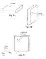
- FIG. 1Aillustrates a single axis accelerometer positioned for measuring lateral acceleration, and included in an accelerometer-gyroscopic sensor in accordance with an embodiment of the present invention.
- FIG. 1Billustrates a dual axis accelerometer positioned for measuring vertical and longitudinal acceleration, and included in an accelerometer-gyroscopic sensor in accordance with an embodiment of the present invention.
- FIG. 2Aillustrates a gyroscope positioned for measuring a heading, and included in an accelerometer-gyroscopic sensor in accordance with all embodiment of the present invention.
- FIG. 2Billustrates a gyroscope positioned for measuring a lateral inclination, and included in an accelerometer-gyroscopic sensor in accordance with an embodiment of the present invention.
- FIG. 2Cillustrates a longitudinal inclination, and included in an accelerometer-gyroscopic sensor in accordance with an embodiment of the present invention.
- FIG. 3Ais a schematic view illustrating the components of the rear-end collision avoidance system, warning drivers of a subject vehicle's deceleration, in accordance with an embodiment of the present invention.
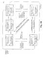
- FIG. 3Billustrates a state machine diagram of the control device in accordance with the preferred embodiment of the present invention.
- FIG. 3Cillustrates a state machine diagram of the control device in accordance with an alternative embodiment of the present invention.
- FIG. 4illustrates a schematic view of an anti-rollover system in accordance with an embodiment of the present invention.
- FIG. 5illustrates a schematic view of an engine performance monitoring system in accordance with an embodiment of the present invention.
- FIG. 6illustrates a schematic view of a suspension and road condition monitoring system in accordance with an embodiment of the present invention.
- FIG. 7illustrates a navigation system in accordance with an embodiment of the present invention.
- the present inventionincludes systems and methods for detecting absolute rates of acceleration of bodies moving relative to a gravitational acceleration.
- the preferred embodimentuses signals from both an accelerometer, which sometimes detects gravitational acceleration in addition to actual vehicle acceleration, and a gyroscope, which can sense deviations from the plane perpendicular to earth's gravity. By modifying the signals from the accelerometer based on those from the gyroscope, the preferred embodiment monitors the absolute acceleration or deceleration of a vehicle relative to the road, or some other body relative to any object that is fixed relative to some gravity source that affects the body.
- the preferred embodiment of the present inventionincludes a dual axis accelerometer and an electronic gyroscope positioned upon a moving body (not shown) having a pitch axis and a yaw axis that form a pitch-yaw plane as illustrated, which attempts to move along a movement vector orthogonal to the pitch-yaw plane.
- a first axis, termed the longitudinal axis, of the dual axis accelerometeris placed orthogonal to the plane of the pitch and yaw axes to sense acceleration along the movement vector.
- a second axis, termed the vertical axis, of the accelerometeris placed parallel with the yaw axis (and thus perpendicular to the movement vector) to sense acceleration along the yaw axis.
- the two axes of the accelerometerform a longitudinal-vertical plane orthogonal to the pitch-yaw, plane.
- the gyroscope in FIG. 2Cis mounted parallel to the longitudinal-vertical plane of the accelerometer and thus is also along a plane perpendicular to the pitch-yaw plane of the moving body. This configuration allows it to sense an inclination of the movement vector of the moving body relative to the gravitational acceleration acting on the body.
- additional gyroscopes and accelerometersare mounted on the moving body at other orientations. Output from these additional sensors is useful for anti-roll suspension adjustment, among other things.
- the orientations shown in FIGS. 1A and 2Ballow for detection of lateral acceleration and inclination.
- a single axis accelerometerconfigured with a first axis, termed the lateral axis, parallel to the pitch axis senses lateral acceleration of the body, e.g. acceleration in a plane orthogonal to the longitudinal-vertical plane.
- FIG. 2Bdepicts a gyroscope configured parallel to the pitch-yaw plane and thus configured to detect an inclination of the component of movement that lies along the lateral axis, termed the lateral inclination of the body.
- the systemalso includes another gyroscope that is configured parallel to the lateral-longitudinal plane (in which all desirable movement vectors will lie), to detect a heading of the body.
- This additional gyroscopeis required for those embodiments that supply supplemental data to navigation systems.
- the embodiments of the present inventioninclude logic circuits configured to receive signals of acceleration along the lateral, longitudinal, and vertical axes, as well as of the lateral and longitudinal inclinations and the heading, and to process these signals to produce a variety of output signals indicating characteristics of the moving body's movement.
- Thesepreferably include: absolute longitudinal acceleration (both positive and negative), absolute vertical acceleration (both positive and negative), absolute lateral acceleration (both positive and negative), heading, and actual speed.
- gyroscopesboth mechanical and electronic, can suffer from instability and drift. Because of these drift characteristics, gyroscopes typically require periodic auto-zeroing or re-referencing to provide reliable output.
- a method of detecting an absolute decelerationincludes steps of re-referencing. This task is preferably accomplished using signals from the accelerometers, but in other embodiments use a Hall effect, electronic or other type of compass.
- Re-referencingpreferably takes place periodically; for systems using Hall effect or some other independent compass, the systems simply re-reference at specified heading or timing intervals.
- systems that use accelerometer data for re-referencingare preferably more careful.
- any signal from the accelerometeris essentially representative of the earth's gravity, this signal can provide an initial reference for any gyroscopes included in the present invention, which preferably takes place prior to movement of the body.
- the gyroscope outputcan become unreliable.
- the present inventionteaches several methods of re-referencing during travel. Some of these are only applicable to travel that includes periodic stops.
- the vertical or lateral axis accelerometerscan be used to detect whether the body is stopped. When it is stopped, the signal from the longitudinal axis of the accelerometer can be used to re-reference the gyroscope. Further, at any point during travel when no acceleration has been detected for a predetermined period of time the gyroscope can be re-referenced. In this way repeated referencing can occur even during extended travel without any stops.
- the present inventionis preferably implemented in a vehicle, and the following embodiments of the present invention are described relative to a vehicle.
- the methods and systems taught by the present inventioncan be implemented in a wide variety of moving bodies other than vehicles.
- the devices described above with reference to FIGS. 1A , 1 B, 2 A, 2 B, and 2 Care termed an “accelerometer-gyroscopic sensor” when referenced elsewhere.
- FIG. 3Ais a schematic view illustrating the components of the rear-end collision avoidance system 300 , warning drivers of a subject vehicle's deceleration, in accordance with one embodiment of the present invention.
- the rear-end collision avoidance system 300comprises an accelerometer-gyroscopic sensor 310 , a braking system engagement detector 320 , a throttle engagement detector 330 , and a control device 340 .
- the accelerometer-gyroscopic sensor 310is coupled to the control device 340 , detects an absolute longitudinal deceleration of the vehicle, and sends a signal to the control device 340 .
- the braking system engagement detector 320is also coupled to the control device 340 , detects any engagement of the braking system of the vehicle, and sends a signal to the control device 340 .
- the throttle engagement detector 330is also coupled to the control device 340 and detects engagement of the throttle.
- the present inventionalso includes additional input devices, such as a clutch engagement detector configured to relay a clutch status to the control device 340 .
- the control device 340processes the input signals it receives from the accelerometer-gyroscopic sensor 310 , the braking system engagement detector 320 , and the throttle engagement detector 330 and decides whether to activate an alerting device of the vehicle. In some embodiment the control device 340 only activates an alerting device if the vehicle is throttled down but not braking.
- control device 340activates the alerting device only if the absolute longitudinal deceleration is non-zero.
- the communication systemfurther comprises an alerting device activation circuit 350 , wherein the control device 340 is coupled to and sends signals to the alerting device activation circuit 350 , which activates an alerting device based on a signal from the control device 340 .
- the embodiments of the present inventioninclude input devices. Those mentioned above include braking system engagement detectors, throttle engagement detectors, and the accelerometer-gyroscopic sensor. In alternative embodiments, the present invention also includes additional input devices, such as a clutch engagement detector configured to relay a clutch status to the control device.
- an alerting devicepreferably comprises lamps on the vehicle that are capable of flashing and emitting visible light.
- the lamps of the alerting deviceflash only at a constant rate, while in another aspect the lamps flash at a variable rate, and further wherein the control device is configured to flash the lamps at a rate correlated to a rate of deceleration.
- the lampsare preferably one of the following: conventional signaling lamps and conventional brake lamps.
- the alerting deviceis a radio frequency (RF) transmitter capable of directing RF signals from the rear of the vehicle to a following vehicle. In other embodiments, the alerting device uses other types of signals.
- RFradio frequency
- inventionsand “conventional brake lamps” refer to signaling or brake lamps included on motor vehicles during their original manufacture.
- the present inventionalso contemplates signaling by using after-market devices that are attached to a vehicle in addition to conventional signaling and brake lamps.
- a communication systemcan be embodied as an after-market add-on product or as an original vehicle system. These embodiments include different types of controllers.
- a control devicepreferably does not interfere with the existing brake lamp system controller.
- the control devicecommunicates with the brake lamps in a substantially separate manner from the existing brake lamp control system.
- Control devices used in the present inventioncould include relays, switches or micro controllers.
- an aftermarket systemcan continuously power the alerting device activation circuit without need of an intermediate control device.
- a communication system in accordance with the present inventionpreferably includes a control device that further comprises a control system for the conventional brake lamp system, whereby the communication system is an integrated control and circuitry system for all brake lamps.
- a single control systemaccomplishes the tasks of conventional brake signaling and the signaling described in the present invention.
- the communications system of the present inventionuses information from the various input devices to determine a manner in which to operate all alerting device.
- the communications systemcontinuously modulates the alerting device based on the accelerometer-gyroscopic sensor's input so long as the throttle is disengaged, regardless of braking system status.
- the communications systemactivates the alerting device continuously until disengagement of the braking system, whereupon the communications system once again considers throttle and the accelerometer-gyroscopic sensor's input in choosing a manner in which to operate the alerting device.
- the control devicedeactivates in response to braking system engagement and reactivates upon braking system disengagement.
- the control devicereceives input in cycles and makes a determination for operation of the alerting device within each cycle.
- the control device 340takes input from the accelerometer-gyroscopic sensor 310 , the braking system engagement detector 320 , and the throttle engagement detector 330 in cycles that are substantially continuous in time. In the preferred embodiment, for each cycle, the control device 340 enters one of four states: I) it does not activate an alerting device for the entirety of the cycle, II) it activates an alerting device for the entirety of the cycle, III) it activates an alerting device at least once for a period of time that is short relative to the duration of the cycle; or IV) it activates an alerting device multiple times during the cycle.
- FIG. 3Billustrates a preferred embodiment in which these four output states are handled.
- a state machine 301included in a control device in accordance with the present invention, takes five possible input states, for four of them throttle status is not considered: 1 ) brake pedal is not depressed, absolute deceleration is not detected; 2 ) brake pedal is not depressed, absolute deceleration is detected; 3 ) brake pedal is depressed, absolute deceleration is detected; or 4 ) brakes pedal is depressed, absolute deceleration is not detected. State 5 ) only occurs if the throttle is disengaged, and if the brake pedal is not depressed.
- Input state 1corresponds to output state I
- input state 2corresponds to output state III
- input states 3 and 5correspond to output state II
- input state 4corresponds to output state IV.
- Transitions between all input statesare handled and every transition is a plausible outcome of a braking or acceleration event.
- a driver disengaging the throttle pedalcauses a transition from state 1 to state 5 .
- the brake lampsare illuminated. Once a required level of absolute deceleration is detected, a transition from state 5 to state 2 occurs.
- the brake lampsare flashed, or another alerting device is activated, corresponding to output state III.
- a transition from state 1 directly to state 2can occur when beginning ascent of a steep grade: the throttle is engaged, the brake pedal is disengaged but the vehicle begins to decelerate.
- a transition from state 5 to state 1 , or state 2 to state 1occurs. If the driver subsequently depresses the brake pedal, a transition from state 2 , or state 5 , to state 3 occurs. While the brake pedal is depressed, state II output keeps the brake lamps illuminated. Furthermore, while the brake pedal is depressed, a transition from state 3 to state 4 may occur. In this embodiment, in state 4 the lamps are flashed at an increased rate. Whenever the brake pedal is depressed, state II or IV output occurs and accelerometer-gyroscopic sensor data is effectively ignored. When the brake pedal is released, one of input state 1 , input state 2 , and input state 5 are entered.
- a transition from input state 3 to 2corresponds to tapping or pumping the brake pedal. Depending on the length of time a cycle comprises, a residual brake lamp flash may occur. Transitions from input states 3 or 4 to state 1 correspond respectively to accelerating from a rolling stop on a hill, or rolling forward downhill. A transition from input state 4 to 2 could arise when rolling down a hill backwards, for example at a stoplight on a hill. This points to another feature of the current system—providing a warning for rollback.
- a state machine 301 ′ included in a control device in accordance with the present inventionthe system only considers the first three states.
- the state machine 301 ′takes four possible input states: 1 ) brake pedal is not depressed, absolute deceleration is not detected; 2 ) brake pedal is not depressed, absolute deceleration is detected; 3 ) brake pedal is depressed, absolute deceleration is detected; or 4 ) brake pedal is depressed, absolute deceleration is not detected.
- Input state 1corresponds to output state I
- input state 2corresponds to output state III
- input states 3 and 4correspond to output state II.
- Transitions between all input statesare handled and every transition is a plausible outcome of a braking or acceleration event.
- a driver taking his or her foot off the accelerator pedalcauses a transition from state 1 to state 2 .
- the brake lampsare flashed, or other alerting means are activated, corresponding to output state III.
- This transition from state 1 to state 2also occurs when beginning ascent of a steep grade: the accelerator is depressed, the brake pedal is disengaged but the vehicle begins to decelerate. If the driver presses the accelerator again, or in the case of an ascent, further depresses the accelerator, a transition from state 2 to state 1 occurs. If the driver subsequently depresses the brake pedal, a transition from state 2 to state 3 occurs.
- state II outputkeeps the brake lamps illuminated. Furthermore, while the brake pedal is depressed, a transition from state 3 to state 4 may occur. In this embodiment, such a transition results in no change in output. Whenever the brake pedal is depressed, state II output occurs and accelerometer-gyroscopic sensor data is effectively ignored. When the brake pedal is released, either input state 1 or input state 2 is entered.
- Transitions between states in this embodimentare similar to those in the preferred embodiment.
- a transition from input state 3 to 2corresponds to tapping or pumping the brake pedal.
- a cyclecomprises, a residual brake lamp flash may occur.
- Transitions from input states 3 or 4 to state 1correspond respectively to accelerating from a rolling stop on a hill, or rolling forward downhill.
- a transition from input state 4 to 2could arise when rolling down a hill backwards, for example at a stoplight on a hill. This points to another feature of the current system—providing a warning for rollback.
- Embodiments of the present inventionprovide the driver of a subject vehicle a communication system that provides warning signals to other vehicles of any absolute deceleration or possibility of braking of the subject vehicle.
- One novel and distinguishing feature of this inventionis that the subject vehicle's communication system warns other vehicles of any possibility that the subject vehicle will begin to brake. This is so because any engagement of the brake pedal is usually immediately preceded by a disengagement of the throttle.
- this inventionprovides an earlier warning to the driver of the following vehicle of a subject vehicle's intent to decelerate than is currently available in modern vehicles, which only provide systems that actuate warning lamps if the driver depresses the brake pedal or if an accelerometer unit detects a threshold deceleration.
- Modern driversrespond quickly to rear brake warning lamps, conditioning that the present invention takes advantage of by using these warning systems to convey new and broader warnings. Since following distances on modern roadways are often inadequate, this arrangement could prevent numerous rear-end collisions.
- outputs from the sensing of absolute lateral accelerationare used to adjust suspension systems by stiffening outside suspension and/or loosening inside suspension of moving vehicles.
- lateral acceleration or forceWhen lateral acceleration or force is applied to a vehicle, it tends to lean in the direction opposite to the force being applied, due in part to the softness of their suspension systems. This moves the center of gravity further off center and in some cases outside of their wheelbase approaching the critical rollover point. Stiffening the outside suspension and/or loosening the inside suspension keeps the center of gravity of vehicles within a tighter envelope relative to the wheelbase. This inversely affects the propensity, especially in high center of gravity loaded vehicles to rollover when the center of gravity of their load exceeds the wheelbase and reaches the critical rollover point. Additionally, by adjusting the suspension system in this manner the distribution of load between left and right side wheels is kept more even resulting in improved traction.
- PWMpulse width modulated
- Such devicestypically accept analog voltage level inputs, which are then converted to a corresponding pulse width output.
- Such outputsare a common method of controlling and delivering a regulated amount of current to a device such as a hydraulic solenoid.
- the hydraulic solenoidsof course are responsible for increasing, decreasing or maintaining pressure levels within the hydraulic or pneumatic suspension system.
- An anti-rollover device 400is illustrated in FIG. 4 .
- vehiclesare assumed to be equipped with adjustable suspension systems, typically hydraulic or pneumatic.
- the accelerometer-gyroscopic sensor 410sends a signal representing absolute lateral acceleration to a suspension selector 420 , which passes signals along to a controller responsible for controlling the relevant quadrant of the suspension.
- the suspension selector 420must interpret the signal to determine the appropriate quadrant.
- Q 1 in which suspension system 432 is controlled by suspension control 431could be the right front wheel
- Q 2in which suspension system 442 is controlled by suspension control 441 could be the left front wheel
- Q 3in which suspension system 452 is controlled by suspension control 451 could be the right rear wheel
- Q 4in which suspension system 462 is controlled by suspension control 461 could be the left rear wheel.
- other orderingsare possible, as are systems with only two independent zones, e.g. two sides are controlled in lockstep.
- the absolute accelerometer/gyroscope combinationprovides the ability to communicate actual power-to-the-ground data for use in engine/vehicle performance computations.
- the accelerometer-gyroscopic sensorcontinuously sums absolute acceleration values to provide both absolute acceleration and actual speed values, which can be used by a manufacturers vehicle computer unit (VCU).
- VCUvehicle computer unit
- the system 500 shown in FIG. 5includes the accelerometer-gyroscopic sensor 510 , which delivers actual speed data and absolute acceleration data to a vehicle computer unit (VCU) 520 (or at least the engine monitoring portion thereof).
- VCUvehicle computer unit
- the VCU 520uses baseline engine performance data 540 to either self-correct through a feedback mechanism, or to issue a warning through the performance warning system.
- the manufacturer's baseline engine performance datais helpful in determining how much acceleration should be achieved for a given amount of throttle and what the speed of the vehicle should be for a given amount of throttle. For instance, a VCU may have tuned to maximum efficiency however the vehicle's corresponding speed or acceleration may be many percentage points less than what would be expected, indicating perhaps that the tire pressure is low or that the vehicle is loaded to a higher level than what would be normal, in which case the tire pressure should be increased.
- an accelerometer-gyroscopic sensorwhich is used and is part of this invention can use one axis of a dual axis accelerometer in the vertical position vertical acceleration output signals are made available to other monitors or computers that require this information. Such a requirement may be to monitor and evaluate road quality and/or shock absorber utilization and performance. For instance, it is apparent to a rider in a vehicle when such vehicle is riding on worn out shock absorbers. However, it becomes less apparent when those shock absorbers wear out slowly over an extended period of time. The first time a driver may realize that shock absorbers have worn out is in cases where critical performance is required. Or when they replace worn out tires and see the evidence on tires of worn out shock absorbers. The absolute A/G sensor detects vertical acceleration in very small increments. Increasing levels of vertical acceleration can easily be monitored thus providing notice to drivers of the degradation of shock absorber system.
- the accelerometer-gyroscopic sensor 610provides absolute vertical acceleration data to a VCU 620 or at least a suspension-monitoring portion thereof.
- the VCU 620can use baseline suspension performance data 640 to either self-correct through a feedback mechanism or issue a warning through the suspension warning system 630 .
- the accelerometer-gyroscopic sensoris continuously monitoring acceleration; a unit of acceleration multiplied by a unit of time yields a unit of velocity (with speed as its magnitude).
- the accelerometer-gyroscopic sensorcontinuously sums units of acceleration over small increments of time.
- the accelerometer-gyroscopic sensorprovides the integrated velocity or speed as an output.
- the accelerometer-gyroscopic sensoralso provides direction or heading as an output.
- the accelerometer-gyroscopic sensor 710provides actual speed and heading information as an output to a navigation system controller 720 .
- the navigation system controller 720which normally provides navigation data from a global positioning system (GPS) 730 directly to the navigation system input/output (I/O) 750 , incorporates heading information from the accelerometer-gyroscopic sensor 710 during periods of connection loss with the GPS satellite system.
- GPSglobal positioning system
- I/Oinput/output
- the navigation controllerreceives navigation data from the inertial system to supplement or replace its GPS data.
- the navigation system controller 720also provides GPS heading data back to the accelerometer-gyroscopic sensor 710 to permit re-referencing of the gyroscopes contained therein.
- Continuous referencing and re-referencing of the horizontally mounted gyroscopeutilize GPS heading values while satellite signals are acquired. Once satellite signals are lost gyroscopic heading values take priority using last known valid headings from the GPS. This method using absolute A/G values for supplementing data to the GPS data when the GPS system has lost signal will find use in many applications outside of the automotive industry.
- output signal formatare made available to on board GPS based navigation systems through a data port for supplementation during periods of lost or down satellite signals so that the user of a GPS navigation system sees no down time during these periods.
- speed or velocitycan be tracked by summing positive and negative accelerations and multiplying by time, a second multiplication by time can yield distance, which is also useful in navigation.
- summing positive and negative vertical accelerations over timeyields altitude.
- an instrumentincluding an accelerometer-gyroscopic sensor, placed in an airplane or other flying object, contains a circuit that continuously sums over all accelerations and outputs altitude.
- a system including an accelerometer-gyroscopic sensor included in a non-flying vehicletracks changes in altitude and outputs a signal used to vary engine performance or some other type of parameter.
- This method of altitude determinationhas certain advantages over current methods of determining altitude which rely on either radar, pressure sensors, or GPS triangulation.
- ASLaltitude above sea level
- AGLaltitude above ground level
Landscapes
- Engineering & Computer Science (AREA)
- Mechanical Engineering (AREA)
- Radar, Positioning & Navigation (AREA)
- Remote Sensing (AREA)
- Physics & Mathematics (AREA)
- Transportation (AREA)
- Automation & Control Theory (AREA)
- General Physics & Mathematics (AREA)
- Mathematical Physics (AREA)
- Chemical & Material Sciences (AREA)
- Combustion & Propulsion (AREA)
- Computer Networks & Wireless Communication (AREA)
- Human Computer Interaction (AREA)
- Lighting Device Outwards From Vehicle And Optical Signal (AREA)
- Control Of Driving Devices And Active Controlling Of Vehicle (AREA)
- Traffic Control Systems (AREA)
- Regulating Braking Force (AREA)
Abstract
Description
- Regardless of the individual circumstances, the drivers in these accidents were unable to detect slowed or stopped traffic and to stop their vehicles in time to prevent a rear-end collision. If passenger car drivers have a 0.5-second additional warning time, about 60 percent of rear-end collisions can be prevented. An extra second of warning time can prevent about 90 percent of rear-end collisions. [NTSB Special Investigative Report SIR—01/01, Vehicle-and Infrastructure-based Technology for the Prevention of Rear-end Collisions]
Claims (20)
Priority Applications (1)
| Application Number | Priority Date | Filing Date | Title |
|---|---|---|---|
| US12/499,616US8571776B2 (en) | 2004-10-05 | 2009-07-08 | Absolute acceleration sensor for use within moving vehicles |
Applications Claiming Priority (4)
| Application Number | Priority Date | Filing Date | Title |
|---|---|---|---|
| US61640004P | 2004-10-05 | 2004-10-05 | |
| US11/243,364US7239953B2 (en) | 2004-10-05 | 2005-10-03 | Absolute acceleration sensor for use within moving vehicles |
| US11/821,352US8532896B2 (en) | 2004-10-05 | 2007-06-21 | Absolute acceleration sensor for use within moving vehicles |
| US12/499,616US8571776B2 (en) | 2004-10-05 | 2009-07-08 | Absolute acceleration sensor for use within moving vehicles |
Related Parent Applications (1)
| Application Number | Title | Priority Date | Filing Date |
|---|---|---|---|
| US11/821,352ContinuationUS8532896B2 (en) | 2004-10-05 | 2007-06-21 | Absolute acceleration sensor for use within moving vehicles |
Publications (2)
| Publication Number | Publication Date |
|---|---|
| US20090276131A1 US20090276131A1 (en) | 2009-11-05 |
| US8571776B2true US8571776B2 (en) | 2013-10-29 |
Family
ID=36126602
Family Applications (8)
| Application Number | Title | Priority Date | Filing Date |
|---|---|---|---|
| US11/243,364Expired - Fee RelatedUS7239953B2 (en) | 2004-10-05 | 2005-10-03 | Absolute acceleration sensor for use within moving vehicles |
| US11/821,352Expired - Fee RelatedUS8532896B2 (en) | 2004-10-05 | 2007-06-21 | Absolute acceleration sensor for use within moving vehicles |
| US12/499,616Active2028-11-23US8571776B2 (en) | 2004-10-05 | 2009-07-08 | Absolute acceleration sensor for use within moving vehicles |
| US13/897,209Expired - Fee RelatedUS8725380B2 (en) | 2004-10-05 | 2013-05-17 | Absolute acceleration sensor for use within moving vehicles |
| US14/263,629Expired - LifetimeUS9381902B2 (en) | 2004-10-05 | 2014-04-28 | Absolute acceleration sensor for use within moving vehicles |
| US15/176,033Expired - LifetimeUS9834215B2 (en) | 2004-10-05 | 2016-06-07 | Absolute acceleration sensor for use within moving vehicles |
| US15/425,888Expired - Fee RelatedUS10384682B2 (en) | 2004-10-05 | 2017-02-06 | Absolute acceleration sensor for use within moving vehicles |
| US15/799,581AbandonedUS20180065634A1 (en) | 2004-10-05 | 2017-10-31 | Absolute acceleration sensor for use within moving vehicles |
Family Applications Before (2)
| Application Number | Title | Priority Date | Filing Date |
|---|---|---|---|
| US11/243,364Expired - Fee RelatedUS7239953B2 (en) | 2004-10-05 | 2005-10-03 | Absolute acceleration sensor for use within moving vehicles |
| US11/821,352Expired - Fee RelatedUS8532896B2 (en) | 2004-10-05 | 2007-06-21 | Absolute acceleration sensor for use within moving vehicles |
Family Applications After (5)
| Application Number | Title | Priority Date | Filing Date |
|---|---|---|---|
| US13/897,209Expired - Fee RelatedUS8725380B2 (en) | 2004-10-05 | 2013-05-17 | Absolute acceleration sensor for use within moving vehicles |
| US14/263,629Expired - LifetimeUS9381902B2 (en) | 2004-10-05 | 2014-04-28 | Absolute acceleration sensor for use within moving vehicles |
| US15/176,033Expired - LifetimeUS9834215B2 (en) | 2004-10-05 | 2016-06-07 | Absolute acceleration sensor for use within moving vehicles |
| US15/425,888Expired - Fee RelatedUS10384682B2 (en) | 2004-10-05 | 2017-02-06 | Absolute acceleration sensor for use within moving vehicles |
| US15/799,581AbandonedUS20180065634A1 (en) | 2004-10-05 | 2017-10-31 | Absolute acceleration sensor for use within moving vehicles |
Country Status (1)
| Country | Link |
|---|---|
| US (8) | US7239953B2 (en) |
Cited By (22)
| Publication number | Priority date | Publication date | Assignee | Title |
|---|---|---|---|---|
| US20130103276A1 (en)* | 2010-02-10 | 2013-04-25 | Drivec Ab | Method and apparatus for evaluating deceleration of a vehicle |
| US9217380B2 (en) | 2004-10-05 | 2015-12-22 | Vision Works Ip Corporation | Absolute acceleration sensor for use within moving vehicles |
| US9327726B2 (en) | 2004-10-05 | 2016-05-03 | Vision Works Ip Corporation | Absolute acceleration sensor for use within moving vehicles |
| US9371002B2 (en) | 2013-08-28 | 2016-06-21 | Vision Works Ip Corporation | Absolute acceleration sensor for use within moving vehicles |
| US9381902B2 (en) | 2004-10-05 | 2016-07-05 | Vision Works Ip Corporation | Absolute acceleration sensor for use within moving vehicles |
| US9550452B2 (en) | 2004-10-05 | 2017-01-24 | Vision Works Ip Corporation | Early warning of vehicle deceleration |
| US9643538B2 (en) | 2004-10-05 | 2017-05-09 | Vision Works Ip Corporation | Absolute acceleration sensor for use within moving vehicles |
| US9830821B2 (en) | 2004-10-05 | 2017-11-28 | Vision Works Ip Corporation | Absolute acceleration sensor for use within moving vehicles |
| US9834184B2 (en) | 2013-09-13 | 2017-12-05 | Vision Works Ip Corporation | Trailer braking system and controller |
| US9855986B2 (en) | 2013-08-28 | 2018-01-02 | Vision Works Ip Corporation | Absolute acceleration sensor for use within moving vehicles |
| US9878693B2 (en) | 2004-10-05 | 2018-01-30 | Vision Works Ip Corporation | Absolute acceleration sensor for use within moving vehicles |
| US10046694B2 (en) | 2004-10-05 | 2018-08-14 | Vision Works Ip Corporation | Absolute acceleration sensor for use within moving vehicles |
| CN108928416A (en)* | 2017-05-22 | 2018-12-04 | 上海摩亭网络科技有限公司 | Taillight control method and device, electric two-wheel vehicle |
| US10987989B2 (en) | 2017-06-09 | 2021-04-27 | Polaris Industries Inc. | Adjustable vehicle suspension system |
| US10987987B2 (en) | 2018-11-21 | 2021-04-27 | Polaris Industries Inc. | Vehicle having adjustable compression and rebound damping |
| US11110913B2 (en) | 2016-11-18 | 2021-09-07 | Polaris Industries Inc. | Vehicle having adjustable suspension |
| US11124036B2 (en) | 2012-11-07 | 2021-09-21 | Polaris Industries Inc. | Vehicle having suspension with continuous damping control |
| US11285964B2 (en) | 2014-10-31 | 2022-03-29 | Polaris Industries Inc. | System and method for controlling a vehicle |
| US11318627B2 (en)* | 2018-02-14 | 2022-05-03 | Omron Corporation | Sensor unit, control method, and recording medium |
| US11904648B2 (en) | 2020-07-17 | 2024-02-20 | Polaris Industries Inc. | Adjustable suspensions and vehicle operation for off-road recreational vehicles |
| US12391116B2 (en) | 2010-06-03 | 2025-08-19 | Polaris Industries Inc. | Adjustable performance for a vehicle |
| US12397878B2 (en) | 2020-05-20 | 2025-08-26 | Polaris Industries Inc. | Systems and methods of adjustable suspensions for off-road recreational vehicles |
Families Citing this family (57)
| Publication number | Priority date | Publication date | Assignee | Title |
|---|---|---|---|---|
| US7494393B2 (en)* | 2004-02-11 | 2009-02-24 | Econtrols, Inc. | Watercraft speed control device |
| US7485021B2 (en)* | 2004-02-11 | 2009-02-03 | Econtrols, Inc. | Watercraft speed control device |
| US20080243321A1 (en) | 2005-02-11 | 2008-10-02 | Econtrols, Inc. | Event sensor |
| US7494394B2 (en)* | 2004-02-11 | 2009-02-24 | Econtrols, Inc. | Watercraft speed control device |
| US8475221B1 (en) | 2004-02-11 | 2013-07-02 | Econtrols, Inc. | Watercraft speed control device |
| US8145372B2 (en)* | 2004-02-11 | 2012-03-27 | Econtrols, Inc. | Watercraft speed control device |
| US8521348B1 (en) | 2004-02-11 | 2013-08-27 | Econtrols, Inc. | Watercraft speed control device |
| US7877174B2 (en) | 2005-02-11 | 2011-01-25 | Econtrols, Inc. | Watercraft speed control device |
| US7491104B2 (en)* | 2004-02-11 | 2009-02-17 | Econtrols, Inc. | Watercraft speed control device |
| US7465203B2 (en)* | 2004-02-11 | 2008-12-16 | Econtrols, Inc. | Watercraft speed control device |
| US9052717B1 (en) | 2004-02-11 | 2015-06-09 | Enovation Controls, Llc | Watercraft speed control device |
| NZ532868A (en)* | 2004-05-11 | 2007-02-23 | Stewart Grant Andrews | Vehicle braking warning apparatus |
| US9207675B1 (en) | 2005-02-11 | 2015-12-08 | Enovation Controls, Llc | Event sensor |
| JP4735195B2 (en)* | 2005-11-01 | 2011-07-27 | アイシン・エィ・ダブリュ株式会社 | Vehicle control system |
| DE102005059688A1 (en)* | 2005-12-14 | 2007-06-21 | Daimlerchrysler Ag | Motor vehicle with an Auffahrwarnvorrichtung |
| EP1818233B1 (en)* | 2006-02-14 | 2011-09-07 | Ford Global Technologies, LLC | Deceleration warning device and method for a vehicle |
| EP2025178A2 (en)* | 2006-05-31 | 2009-02-18 | TRX Systems, Inc. | Method and system for locating and monitoring first responders |
| US20080085642A1 (en)* | 2006-10-04 | 2008-04-10 | Econtrols, Inc. | Method for engaging a watercraft speed control system |
| WO2008058307A1 (en)* | 2006-11-15 | 2008-05-22 | Radio Terminal Systems Pty Ltd | Vehicle movement processing system |
| JP5219378B2 (en)* | 2007-01-18 | 2013-06-26 | 株式会社日立製作所 | Interaction data display device, processing device, and display method |
| US8285447B2 (en)* | 2007-03-20 | 2012-10-09 | Enpulz, L.L.C. | Look ahead vehicle suspension system |
| US9733091B2 (en) | 2007-05-31 | 2017-08-15 | Trx Systems, Inc. | Collaborative creation of indoor maps |
| US9448072B2 (en)* | 2007-05-31 | 2016-09-20 | Trx Systems, Inc. | System and method for locating, tracking, and/or monitoring the status of personnel and/or assets both indoors and outdoors |
| US9395190B1 (en) | 2007-05-31 | 2016-07-19 | Trx Systems, Inc. | Crowd sourced mapping with robust structural features |
| JP5114123B2 (en)* | 2007-07-24 | 2013-01-09 | トヨタ自動車株式会社 | In-vehicle device control system |
| GB2454224B (en)* | 2007-11-01 | 2013-01-23 | Haldex Brake Products Ltd | Vehicle stability control apparatus |
| US9157737B2 (en) | 2008-06-11 | 2015-10-13 | Trimble Navigation Limited | Altimeter with calibration |
| US8150651B2 (en) | 2008-06-11 | 2012-04-03 | Trimble Navigation Limited | Acceleration compensated inclinometer |
| US7856336B2 (en) | 2008-06-11 | 2010-12-21 | Trimble Navigation Limited | Forward-looking altitude detector |
| US8566034B1 (en) | 2008-06-11 | 2013-10-22 | Trimble Navigation Limited | Inclinometer with calibration |
| US8841999B2 (en) | 2010-06-26 | 2014-09-23 | Vectolabs, Llc | Deceleration rate indicator apparatus |
| US20120109421A1 (en)* | 2010-11-03 | 2012-05-03 | Kenneth Scarola | Traffic congestion reduction system |
| US9649972B2 (en) | 2011-04-07 | 2017-05-16 | Pioneer Corporation | System for detecting surrounding conditions of moving body |
| US9156372B1 (en) | 2011-04-26 | 2015-10-13 | Enovation Controls, Llc | Multinodal ballast and trim control system and method |
| WO2013049819A1 (en)* | 2011-09-30 | 2013-04-04 | Ims Solutions, Inc. | A method of correcting the orientation of a freely installed accelerometer in a vehicle |
| JP5655831B2 (en)* | 2012-09-13 | 2015-01-21 | トヨタ自動車株式会社 | Driving environment estimation apparatus and method |
| KR101327098B1 (en)* | 2012-09-24 | 2013-11-22 | 현대자동차주식회사 | The shift quality metric of automatic transmission based on human factors method |
| US11156464B2 (en) | 2013-03-14 | 2021-10-26 | Trx Systems, Inc. | Crowd sourced mapping with robust structural features |
| US11268818B2 (en) | 2013-03-14 | 2022-03-08 | Trx Systems, Inc. | Crowd sourced mapping with robust structural features |
| US20150062935A1 (en)* | 2013-08-28 | 2015-03-05 | Vision Works Ip Corporation | Absolute acceleration sensor for use within moving vehicles |
| JP6042308B2 (en)* | 2013-10-29 | 2016-12-14 | 本田技研工業株式会社 | Vehicle collision determination device |
| KR101539207B1 (en) | 2015-02-16 | 2015-07-30 | (주)유양디앤유 | Safety Apparatus for Vehicle Using Visible Light Communication |
| JP6311648B2 (en)* | 2015-05-29 | 2018-04-18 | 株式会社デンソー | Collision mitigation device |
| US10336247B2 (en) | 2016-06-27 | 2019-07-02 | Deceleration Technologies, LLC | Apparatus and method for automatic application/deapplication of brake lights |
| US11046241B2 (en)* | 2016-07-11 | 2021-06-29 | Jefferey B Hammock | Deceleration-triggered automatic brake indication |
| US10315559B2 (en)* | 2016-07-11 | 2019-06-11 | Jeffery Hammock | Systems, apparatus, and methods for signaling sudden deceleration |
| US10029697B1 (en)* | 2017-01-23 | 2018-07-24 | GM Global Technology Operations LLC | Systems and methods for classifying driver skill level |
| TWI614173B (en)* | 2017-02-21 | 2018-02-11 | Chen De Sheng | Self-generating warning device and traffic vehicle including the same |
| CN109238293A (en)* | 2017-07-10 | 2019-01-18 | 李公健 | A kind of system and method for long-range management bicycle parking posture |
| CN107672580A (en)* | 2017-09-27 | 2018-02-09 | 交通运输部公路科学研究所 | A kind of the automobile long dynamic monitoring of down hill braking efficiency, warning system and method |
| CN110095635B (en)* | 2019-05-08 | 2021-06-04 | 吉林大学 | Longitudinal speed estimation method of all-wheel drive vehicle |
| DE102019212300A1 (en)* | 2019-08-16 | 2021-02-18 | Zf Friedrichshafen Ag | Method for determining a longitudinal acceleration of a motor vehicle |
| JP7432853B2 (en)* | 2019-09-27 | 2024-02-19 | パナソニックIpマネジメント株式会社 | Shock detection device and power storage pack |
| CN111452792A (en)* | 2020-03-09 | 2020-07-28 | 北汽福田汽车股份有限公司 | Vehicle control method and system |
| CN112160836B (en)* | 2020-09-25 | 2021-12-07 | 兰州万里航空机电有限责任公司 | Motor drive control circuit for aviation air door electric mechanism |
| CN116547185A (en)* | 2020-11-20 | 2023-08-04 | 沃尔沃卡车集团 | Method for controlling a drive train of a vehicle |
| CN113071469B (en)* | 2021-04-06 | 2021-11-16 | 深圳市明华澳汉智能卡有限公司 | Motor vehicle steering and braking alarm system based on RFID |
Citations (71)
| Publication number | Priority date | Publication date | Assignee | Title |
|---|---|---|---|---|
| US3725921A (en) | 1970-11-04 | 1973-04-03 | Bendix Corp | Traffic responsive speed control system |
| US4344139A (en) | 1980-05-07 | 1982-08-10 | Caterpillar Tractor Co. | Method and apparatus for controlling differentially driven wheel slip |
| US4349233A (en) | 1980-05-07 | 1982-09-14 | Caterpillar Tractor Co. | Method and apparatus for controlling wheel slip on differentially mounted wheels |
| US4361871A (en) | 1980-05-07 | 1982-11-30 | Caterpillar Tractor Co. | Failsafe wheel slip control system and method of operating same |
| US4402142A (en) | 1980-09-04 | 1983-09-06 | Dinsmore Robert C | Electronic compass for automotive vehicles |
| US4542460A (en) | 1982-02-16 | 1985-09-17 | Weber Harold J | Driving aid indicator for economical operation of automatic transmission equipped motor vehicle |
| US4779696A (en) | 1986-07-24 | 1988-10-25 | Mazda Motor Corporation | Vehicle slip control apparatus |
| JPS6430854A (en) | 1987-07-25 | 1989-02-01 | Tsukasa Sakahara | Indicating method for emergency braking of self-traveling vehicle |
| JPH01111550A (en) | 1987-10-26 | 1989-04-28 | Hitachi Constr Mach Co Ltd | Control device for turning on brake lamp of vehicle |
| JPH01145247A (en) | 1987-11-30 | 1989-06-07 | Honda Motor Co Ltd | Lamp device for air spoiler |
| US5314037A (en) | 1993-01-22 | 1994-05-24 | Shaw David C H | Automobile collision avoidance system |
| JPH0939655A (en) | 1995-08-01 | 1997-02-10 | Hitoshi Yamaguchi | Multicolor led high mount lamp for vehicle |
| US5770999A (en) | 1993-06-16 | 1998-06-23 | Rhodes; Michael E. | Vehicle light control system |
| US5831162A (en) | 1997-01-21 | 1998-11-03 | Delco Electronics Corporation | Silicon micromachined motion sensor and method of making |
| US5856620A (en) | 1995-05-31 | 1999-01-05 | Wacoh Corporation | Acceleration sensor |
| US6023221A (en) | 1997-08-25 | 2000-02-08 | Michelotti; Paul E | System to activate automobile hazard warning lights |
| US6073070A (en) | 1996-11-16 | 2000-06-06 | Claas Kgaa | Agricultural vehicle with treatment device which is adjustable in its position and/or orientation relative to the vehicle |
| US6085133A (en) | 1992-08-26 | 2000-07-04 | Robert Bosch Gmbh | Method and apparatus for correcting vehicle chassis sensor signals and for controlling a vehicle chassis |
| JP2001206145A (en) | 2000-01-26 | 2001-07-31 | Masao Kitayama | Alarm device and alarm means |
| US20010056544A1 (en) | 1998-06-18 | 2001-12-27 | Walker Richard C. | Electrically controlled automated devices to operate, slow, guide, stop and secure, equipment and machinery for the purpose of controlling their unsafe, unattended, unauthorized, unlawful hazardous and/or legal use, with remote control and accountability worldwide |
| US6351211B1 (en) | 2000-01-25 | 2002-02-26 | M&P Ventures, Inc. | Brake warning method and system |
| US6411204B1 (en) | 1999-11-15 | 2002-06-25 | Donnelly Corporation | Deceleration based anti-collision safety light control for vehicle |
| US6417767B1 (en) | 2000-03-27 | 2002-07-09 | Craig D. Carlson | Device and system for indicating rapid deceleration in vehicles |
| US6417764B2 (en) | 1994-07-15 | 2002-07-09 | Mark Christopher Tonkin | Safety system for vehicles |
| JP2002240624A (en) | 2001-02-16 | 2002-08-28 | Delta Commun:Kk | Rear-end collision preventing safety device |
| US20020133282A1 (en) | 2001-03-16 | 2002-09-19 | Ryan John T. | Brake light system using sequential lamp array and input from velocity measuring device |
| US6459369B1 (en) | 2000-11-22 | 2002-10-01 | Robert Bosch Corporation | Tire deflation detection system with feedback component |
| US20030006886A1 (en) | 1998-05-19 | 2003-01-09 | Gabbard Charles H. | System for disabling vehicles having air brake systems |
| US6525652B2 (en) | 2001-03-02 | 2003-02-25 | Clayton S. Smith | Downshifting warning system |
| US20030039123A1 (en) | 2001-07-19 | 2003-02-27 | Crisick William E. | Motor vehicle safety system |
| US6556908B1 (en) | 2002-03-04 | 2003-04-29 | Ford Global Technologies, Inc. | Attitude sensing system for an automotive vehicle relative to the road |
| US6710709B1 (en) | 2000-04-03 | 2004-03-23 | Louis F. Morin | Motor vehicle safety lights |
| US20040139034A1 (en) | 2000-08-11 | 2004-07-15 | Telanon, Inc. | Automated consumer to business electronic marketplace system |
| US6765495B1 (en) | 2000-06-07 | 2004-07-20 | Hrl Laboratories, Llc | Inter vehicle communication system |
| US20040160315A1 (en) | 2003-02-14 | 2004-08-19 | Speckhart Frank H. | Integrated warning device for providing flashing brake lights |
| US6856883B2 (en) | 2002-03-06 | 2005-02-15 | Chadwick Ray Traylor | Solid-state accelerometer module and system therefor |
| JP2005145333A (en) | 2003-11-18 | 2005-06-09 | Koichiro Matsumoto | Autonomous deceleration indicating device of automobile |
| US20050156727A1 (en) | 2004-01-21 | 2005-07-21 | Golder Thomas J. | Initial movement indicator system and method for a wheeled ground vehicle |
| US20050223762A1 (en) | 2003-05-28 | 2005-10-13 | Yasushi Yamamoto | Parking device for vehicle |
| US20060026017A1 (en) | 2003-10-28 | 2006-02-02 | Walker Richard C | National / international management and security system for responsible global resourcing through technical management to brige cultural and economic desparity |
| US20060074540A1 (en) | 2004-10-05 | 2006-04-06 | Vision Works, Llc | Absolute acceleration sensor for use within moving vehicles |
| JP2006182172A (en) | 2004-12-27 | 2006-07-13 | Ichikoh Ind Ltd | Warning light device for vehicles |
| US7104364B2 (en) | 2002-03-21 | 2006-09-12 | Lucas Automotive Gmbh | Electrically actuatable vehicle brake and method for controlling an electrically actuatable vehicle brake |
| US20060206246A1 (en) | 2004-10-28 | 2006-09-14 | Walker Richard C | Second national / international management and security system for responsible global resourcing through technical management to brige cultural and economic desparity |
| US20070052530A1 (en) | 2003-11-14 | 2007-03-08 | Continental Teves Ag & Co. Ohg | Method and device for reducing damage caused by an accident |
| US20070135980A1 (en) | 2005-12-09 | 2007-06-14 | Smartdrive Systems Inc | Vehicle event recorder systems |
| US20070136078A1 (en) | 2005-12-08 | 2007-06-14 | Smartdrive Systems Inc. | Vehicle event recorder systems |
| US20070135979A1 (en) | 2005-12-09 | 2007-06-14 | Smartdrive Systems Inc | Vehicle event recorder systems |
| US20070188348A1 (en) | 2005-10-12 | 2007-08-16 | Toyota Engineering & Manufacturing North America, Inc. | Method and apparatus for previewing conditions on a highway |
| US20070205882A1 (en) | 2006-03-01 | 2007-09-06 | Wabash National, L.P. | Air tank pressure monitoring |
| US20070219685A1 (en) | 2006-03-16 | 2007-09-20 | James Plante | Vehicle event recorders with integrated web server |
| US20070252723A1 (en) | 2006-04-28 | 2007-11-01 | Boss Gregory J | Dynamic Vehicle Grid Infrastructure to Allow Vehicles to Sense and Respond to Traffic Conditions |
| US20080082261A1 (en) | 2006-09-07 | 2008-04-03 | Nissan Technical Center North America, Inc. | Vehicle on-board unit |
| US20080111666A1 (en) | 2006-11-09 | 2008-05-15 | Smartdrive Systems Inc. | Vehicle exception event management systems |
| US20080120175A1 (en) | 2006-11-20 | 2008-05-22 | Jeff Doering | Driver Input Analysis and Feedback System |
| US20080122652A1 (en) | 2006-09-07 | 2008-05-29 | Nissan Technical Center North America, Inc. | Vehicle on-board unit |
| US20080122605A1 (en) | 2006-09-07 | 2008-05-29 | Nissan Technical Center North America, Inc. | Vehicle on-board unit |
| US20080122603A1 (en) | 2006-11-07 | 2008-05-29 | Smartdrive Systems Inc. | Vehicle operator performance history recording, scoring and reporting systems |
| US20080147266A1 (en) | 2006-12-13 | 2008-06-19 | Smartdrive Systems Inc. | Discretization facilities for vehicle event data recorders |
| US20080147267A1 (en) | 2006-12-13 | 2008-06-19 | Smartdrive Systems Inc. | Methods of Discretizing data captured at event data recorders |
| US20080288192A1 (en) | 2007-04-25 | 2008-11-20 | Ajith Kuttannair Kumar | System and Method For Monitoring The Effectiveness Of A Brake Function In A Powered System |
| US7529609B2 (en) | 2004-10-05 | 2009-05-05 | Vision Works Ip Corporation | Absolute acceleration sensor for use within moving vehicles |
| US20090125170A1 (en) | 2007-04-25 | 2009-05-14 | Joseph Forrest Noffsinger | System and method for optimizing a braking schedule of a powered system traveling along a route |
| US20090242284A1 (en) | 2008-04-01 | 2009-10-01 | Whetstone Jr Henry M | Transportation cart with electronic controls, steering and brakes selectively configured for riding and walking modes of use |
| US20090242285A1 (en) | 2008-04-01 | 2009-10-01 | Whetstone Jr Henry M | Transportation cart with extendable arm and a throttle coupled thereto for controlling a motor and associated methods |
| US20090261963A1 (en) | 2008-04-22 | 2009-10-22 | Ault Scott T | Vehicle Deceleration Warning System |
| US20100063736A1 (en) | 2008-09-05 | 2010-03-11 | Robert Bosch Gmbh | Collision avoidance system and method |
| US20100217507A1 (en) | 2004-10-05 | 2010-08-26 | Vision Works Ip Corporation | Absolute acceleration sensor for use within moving vehicles |
| US20100318258A1 (en) | 2005-07-01 | 2010-12-16 | Tsuyoshi Katayama | Driving recorder |
| US20100332074A1 (en) | 2009-06-26 | 2010-12-30 | Autoliv Asp, Inc. | Enhanced electronic assembly |
| US20100332101A1 (en) | 2004-10-05 | 2010-12-30 | Vision Works Ip Corporation | Absolute acceleration sensor for use within moving vehicles |
Family Cites Families (123)
| Publication number | Priority date | Publication date | Assignee | Title |
|---|---|---|---|---|
| US3846749A (en) | 1973-02-01 | 1974-11-05 | Massachusetts Inst Technology | Vehicle brake light control system |
| US3877299A (en) | 1973-07-25 | 1975-04-15 | Clayton Manufacturing Co | Brake pedal actuator |
| US4195328A (en) | 1978-06-19 | 1980-03-25 | Harris William R Jr | Open vehicle lighting system utilizing detachable vehicle operator helmet mounted light |
| EP0084825A3 (en) | 1982-01-21 | 1984-07-18 | Nissan Motor Co., Ltd. | Engine control system |
| JP2618250B2 (en) | 1987-12-22 | 1997-06-11 | 富士重工業株式会社 | Traction control device |
| JPH01173660A (en) | 1987-12-28 | 1989-07-10 | Stanley Electric Co Ltd | Two-color radiating led |
| US5017904A (en) | 1990-04-16 | 1991-05-21 | General Motors Corporation | Braking indicator system |
| US5381135A (en) | 1992-10-08 | 1995-01-10 | Robert L. Blount | Vehicle deceleration alerting device |
| JP3157923B2 (en)* | 1992-10-20 | 2001-04-23 | パイオニア株式会社 | Distance error correction method for navigation device |
| NZ245165A (en) | 1992-11-18 | 1997-07-27 | Geoffrey Miles Furness | Imminent braking warning monitors drop in pressure on vehicle accelerator pedal |
| JPH06262978A (en) | 1993-03-15 | 1994-09-20 | Nifco Inc | Deceleration display device for car |
| JP3233739B2 (en) | 1993-06-30 | 2001-11-26 | マツダ株式会社 | Car driving control device |
| US5417767A (en)* | 1993-12-28 | 1995-05-23 | Stinson; Mark G. | Wafer carrier |
| JPH07205717A (en) | 1994-01-17 | 1995-08-08 | Hitachi Ltd | Stop lamps for vehicles |
| US5572449A (en) | 1994-05-19 | 1996-11-05 | Vi&T Group, Inc. | Automatic vehicle following system |
| US5654890A (en)* | 1994-05-31 | 1997-08-05 | Lockheed Martin | High resolution autonomous precision approach and landing system |
| JPH0837577A (en) | 1994-07-25 | 1996-02-06 | Hitachi Ltd | Recording device |
| US5594414A (en) | 1994-08-02 | 1997-01-14 | Namngani; Abdulatif | Collision probability detection system |
| US5453662A (en) | 1994-08-10 | 1995-09-26 | Designtech International Inc. | Photocell system for automatic headlight controller with light tube |
| US5473306A (en) | 1994-10-24 | 1995-12-05 | Adell; Robert | Motor vehicle lighting system |
| US5617199A (en) | 1995-04-26 | 1997-04-01 | Laser Technology, Inc. | Device, and associated method, for determining distances between moving objects |
| JP3391145B2 (en) | 1995-05-16 | 2003-03-31 | 市光工業株式会社 | Vehicle deceleration display device |
| US8169311B1 (en) | 1999-12-15 | 2012-05-01 | Automotive Technologies International, Inc. | Wireless transmission system for vehicular component control and monitoring |
| US5657025A (en)* | 1995-08-07 | 1997-08-12 | Litton Systems, Inc. | Integrated GPS/inertial navigation apparatus providing improved heading estimates |
| JP3353101B2 (en) | 1996-07-17 | 2002-12-03 | 矢崎総業株式会社 | Absorption heat pump |
| JP3214364B2 (en) | 1996-08-14 | 2001-10-02 | 富士電機株式会社 | Inter-vehicle distance measuring device |
| US5923286A (en)* | 1996-10-23 | 1999-07-13 | Honeywell Inc. | GPS/IRS global position determination method and apparatus with integrity loss provisions |
| US6020814A (en) | 1997-03-26 | 2000-02-01 | Robert; Ivan N. | Vehicular deceleration warning system |
| US6611610B1 (en) | 1997-04-02 | 2003-08-26 | Gentex Corporation | Vehicle lamp control |
| JPH117496A (en) | 1997-06-16 | 1999-01-12 | Dainippon Printing Co Ltd | Card direction detector |
| JP3762052B2 (en) | 1997-06-27 | 2006-03-29 | 株式会社吉野工業所 | Weighing container |
| US5940026A (en)* | 1997-07-21 | 1999-08-17 | Rockwell Science Center, Inc. | Azimuth determination for GPS/INS systems via GPS null steering antenna |
| JP3603552B2 (en) | 1997-07-22 | 2004-12-22 | 株式会社デンソー | Nozzle device |
| JP4067603B2 (en) | 1997-07-27 | 2008-03-26 | 株式会社ジャストシステム | Document classification apparatus, storage medium storing document classification program, and document classification method |
| US6278945B1 (en)* | 1997-11-24 | 2001-08-21 | American Gnc Corporation | Fully-coupled positioning process and system thereof |
| US6167347A (en)* | 1998-11-04 | 2000-12-26 | Lin; Ching-Fang | Vehicle positioning method and system thereof |
| US6233515B1 (en)* | 1998-12-07 | 2001-05-15 | Jaguar Car, Limited | Adaptive vehicle cruise control system and methodology |
| US6097156A (en) | 1999-02-22 | 2000-08-01 | Diep; Michael T. | Switching control system for automatically turning headlights off and on at intersections |
| JP2001030826A (en) | 1999-07-15 | 2001-02-06 | Teruo Hazumi | Brake light lighting device |
| US6488343B1 (en) | 1999-08-19 | 2002-12-03 | Bendix Commercial Vehicle Systems Llc | Parking control circuit |
| US6298931B1 (en)* | 1999-12-09 | 2001-10-09 | Deere & Company | Tracked vehicle steering control system with non-centered steering wheel |
| JP2001213232A (en) | 2000-02-04 | 2001-08-07 | Toyota Motor Corp | Vehicle deceleration control device |
| GB2368218B (en)* | 2000-06-01 | 2004-04-28 | Furuno Electric Co | System for determining the heading and/or attitude of a body |
| US6408245B1 (en)* | 2000-08-03 | 2002-06-18 | American Gnc Corporation | Filtering mechanization method of integrating global positioning system receiver with inertial measurement unit |
| US6502033B1 (en)* | 2000-10-05 | 2002-12-31 | Navigation Technologies Corp. | Turn detection algorithm for vehicle positioning |
| US6317683B1 (en)* | 2000-10-05 | 2001-11-13 | Navigation Technologies Corp. | Vehicle positioning using three metrics |
| US6600414B2 (en) | 2000-12-20 | 2003-07-29 | Trw Inc. | Apparatus and method for detecting vehicle rollover having a discriminating safing function |
| US6753769B1 (en) | 2001-03-29 | 2004-06-22 | Lawrence T. Elliott | Progressive slow-stop signaling system |
| US20120203557A1 (en) | 2001-03-29 | 2012-08-09 | Gilad Odinak | Comprehensive multiple feature telematics system |
| US6525656B1 (en) | 2001-04-12 | 2003-02-25 | Daimlerchrysler Ag | System for providing advanced warning and road user information |
| DE10217843B4 (en) | 2001-04-24 | 2007-08-02 | Koito Manufacturing Co., Ltd. | Infrared radiation lamp for an automobile |
| US6512976B1 (en)* | 2001-04-27 | 2003-01-28 | Honeywell International Inc. | Method and system for terrain aided navigation |
| US6741169B2 (en) | 2001-07-06 | 2004-05-25 | Trw Inc. | Tire tread integrity monitoring system and method |
| JP2003200782A (en) | 2002-01-08 | 2003-07-15 | Hitachi Kokusai Electric Inc | Vehicle running status display device |
| JP3988466B2 (en) | 2002-01-17 | 2007-10-10 | スズキ株式会社 | Two-light headlight device for motorcycles |
| US6697736B2 (en)* | 2002-02-06 | 2004-02-24 | American Gnc Corporation | Positioning and navigation method and system thereof |
| US20030151502A1 (en) | 2002-02-12 | 2003-08-14 | Bing Kam | Automatic warning signal system for vehicles |
| US20030201885A1 (en) | 2002-03-21 | 2003-10-30 | Currie Joseph Edward | Vehicular throttle idle signal indication |
| US6876945B2 (en)* | 2002-03-25 | 2005-04-05 | Nicholas Jon Emord | Seamless sensory system |
| US8100552B2 (en) | 2002-07-12 | 2012-01-24 | Yechezkal Evan Spero | Multiple light-source illuminating system |
| JP2004086523A (en) | 2002-08-27 | 2004-03-18 | Suzuki Motor Corp | Caution information providing device for vehicles |
| JP3982380B2 (en) | 2002-10-21 | 2007-09-26 | 日産自動車株式会社 | Control device for deceleration of internal combustion engine |
| KR100506765B1 (en) | 2002-11-11 | 2005-08-05 | 전영일 | Apparatus and method for controlling of headlight in vehicle and multi-function structured headlight lamp therefor |
| US6870474B1 (en) | 2002-11-25 | 2005-03-22 | Budd Brothers | Vehicle safety signaling system |
| JP2004217175A (en) | 2003-01-17 | 2004-08-05 | Toyota Motor Corp | Inter-vehicle distance control device |
| US7193559B2 (en)* | 2003-01-21 | 2007-03-20 | Novatel, Inc. | Inertial GPS navigation system with modified kalman filter |
| JP4037774B2 (en) | 2003-02-19 | 2008-01-23 | 富士通テン株式会社 | Radar equipment |
| JP2004255928A (en) | 2003-02-24 | 2004-09-16 | Denso Corp | Vehicle control device |
| JP2004322787A (en) | 2003-04-23 | 2004-11-18 | Nissan Motor Co Ltd | Lane departure prevention device |
| JP2004330950A (en) | 2003-05-09 | 2004-11-25 | Honda Motor Co Ltd | Vehicle safety devices |
| JP4457754B2 (en) | 2003-08-28 | 2010-04-28 | 株式会社デンソー | Automatic headlamp optical axis adjustment device for vehicles |
| JP4402400B2 (en) | 2003-08-28 | 2010-01-20 | オリンパス株式会社 | Object recognition device |
| JP4276058B2 (en) | 2003-09-04 | 2009-06-10 | 進一 土肥 | Automobile driving status display device and its control device |
| US7248964B2 (en)* | 2003-12-05 | 2007-07-24 | Honeywell International Inc. | System and method for using multiple aiding sensors in a deeply integrated navigation system |
| DE10360174B4 (en) | 2003-12-20 | 2007-03-08 | Leuze Lumiflex Gmbh + Co. Kg | Device for monitoring a detection area on a work equipment |
| JP2005178678A (en) | 2003-12-22 | 2005-07-07 | Denso Corp | Automatic adjusting device for optical axis direction of vehicle headlight |
| US7362218B2 (en) | 2004-01-20 | 2008-04-22 | Schrader Bridgeport International, Inc. | Motion detection using a shock sensor in a remote tire pressure monitoring system |
| US7224132B2 (en) | 2004-01-22 | 2007-05-29 | Wavecrest Laboratories, Llc. | Portable range extender operable in automatic and manual modes |
| US7077549B1 (en) | 2004-02-04 | 2006-07-18 | Corliss Joseph J | Vehicle warning light system |
| US7482916B2 (en) | 2004-03-15 | 2009-01-27 | Anita Au | Automatic signaling systems for vehicles |
| US7526103B2 (en) | 2004-04-15 | 2009-04-28 | Donnelly Corporation | Imaging system for vehicle |
| JP2005321958A (en) | 2004-05-07 | 2005-11-17 | Denso Corp | Tire air pressure detection device |
| US7089099B2 (en) | 2004-07-30 | 2006-08-08 | Automotive Technologies International, Inc. | Sensor assemblies |
| JP4599932B2 (en) | 2004-08-06 | 2010-12-15 | アイシン・エィ・ダブリュ株式会社 | Navigation system |
| US9327726B2 (en) | 2004-10-05 | 2016-05-03 | Vision Works Ip Corporation | Absolute acceleration sensor for use within moving vehicles |
| DE102005006528A1 (en) | 2005-02-11 | 2006-08-24 | Patent-Treuhand-Gesellschaft für elektrische Glühlampen mbH | Transmitting device for communication between vehicle drivers with signal output direction in reference vehicle for output of modulated acoustic or optical signals, essentially imperceptible by humans |
| US20090066641A1 (en) | 2005-03-10 | 2009-03-12 | Motus Corporation | Methods and Systems for Interpretation and Processing of Data Streams |
| US20070063824A1 (en) | 2005-08-18 | 2007-03-22 | Gaddy Kent B | Vehicle warning system and detection apparatus |
| US20070233337A1 (en)* | 2005-09-14 | 2007-10-04 | Plishner Paul J | Semi-autonomous guidance system for a vehicle |
| US20070159318A1 (en) | 2006-01-12 | 2007-07-12 | Roser Charles R | Speed reduction warning system |
| US7397141B2 (en) | 2006-01-30 | 2008-07-08 | Deere & Company | Power generator using traction drive electronics of a vehicle |
| US20090040073A1 (en) | 2006-05-31 | 2009-02-12 | Todd Bootes | Deceleration warning light assembly for a personal watercraft or other vehicle |
| US20080183344A1 (en) | 2007-01-30 | 2008-07-31 | Arinc Inc. | Systems and methods for communicating restricted area alerts |
| US8533272B2 (en) | 2007-01-30 | 2013-09-10 | Alcatel Lucent | Method and apparatus for notification and delivery of messages to mobile PC users |
| JP5045210B2 (en) | 2007-04-25 | 2012-10-10 | 株式会社デンソー | Travel information collection device |
| US9191740B2 (en) | 2007-05-04 | 2015-11-17 | Personics Holdings, Llc | Method and apparatus for in-ear canal sound suppression |
| GB2454224B (en) | 2007-11-01 | 2013-01-23 | Haldex Brake Products Ltd | Vehicle stability control apparatus |
| US20090140887A1 (en) | 2007-11-29 | 2009-06-04 | Breed David S | Mapping Techniques Using Probe Vehicles |
| US9215781B2 (en) | 2008-04-16 | 2015-12-15 | Avo Usa Holding 2 Corporation | Energy savings and improved security through intelligent lighting systems |
| US8155847B2 (en) | 2008-06-03 | 2012-04-10 | GM Global Technology Operations LLC | Electronic transmission shifting architecture with maximized availability |
| JP5293367B2 (en) | 2009-04-17 | 2013-09-18 | セイコーエプソン株式会社 | Self-luminous display device and electronic device |
| US8370045B2 (en) | 2009-08-14 | 2013-02-05 | Lockheed Martin Corporation | Starter control valve failure prediction machine to predict and trend starter control valve failures in gas turbine engines using a starter control valve health prognostic, program product and related methods |
| EP2289737B1 (en) | 2009-08-26 | 2018-04-25 | Valeo Vision | Device and method for controlling the power supply of a headlamp |
| US8386042B2 (en) | 2009-11-03 | 2013-02-26 | Medtronic Minimed, Inc. | Omnidirectional accelerometer device and medical device incorporating same |
| US8793064B2 (en) | 2009-12-10 | 2014-07-29 | International Business Machines Corporation | Vehicle fuel efficiency optimization based on vehicle usage patterns |
| CA2727789A1 (en) | 2009-12-23 | 2011-06-23 | Hubert Roberge | Electronically controlled continuously variable transmission with torque limiting system and method thereof |
| US9254781B2 (en) | 2010-02-02 | 2016-02-09 | Craig David Applebaum | Emergency vehicle warning device and system |
| US8537030B2 (en) | 2010-02-15 | 2013-09-17 | Ford Global Technologies, Llc | Pedestrian alert system and method |
| TWI373419B (en) | 2010-02-26 | 2012-10-01 | Univ Nat Taipei Technology | Driving method of road-adapting vehicle headlight |
| US20120075117A1 (en) | 2010-09-26 | 2012-03-29 | James Kaiser | Alert system for detecting an emergency vehicle |
| CN103119268A (en) | 2010-12-07 | 2013-05-22 | 丰田自动车株式会社 | Control device for internal combustion engine |
| JP5761982B2 (en) | 2010-12-15 | 2015-08-12 | 株式会社小糸製作所 | Control device for vehicular lamp |
| US9230439B2 (en) | 2011-05-20 | 2016-01-05 | Otodata Wireless Network Inc. | Method and system for monitoring interactions with a vehicle |
| US8941482B1 (en) | 2011-06-23 | 2015-01-27 | BenJoaquin Tomas Gouverneur | Automating turn indication systems |
| US8688365B2 (en) | 2012-01-18 | 2014-04-01 | International Business Machines Corporation | Method and system for detection of motor vehicle movement to avoid collisions |
| JP5564524B2 (en) | 2012-03-19 | 2014-07-30 | ヤマハ発動機株式会社 | Sub headlight unit and sub headlight system for a vehicle turning in a lean position, and a vehicle turning in a lean position |
| DE102012215100A1 (en) | 2012-08-24 | 2014-02-27 | Continental Teves Ag & Co. Ohg | Method and system for promoting a uniform driving style |
| US9599634B2 (en)* | 2012-12-03 | 2017-03-21 | Vibrado Technologies, Inc. | System and method for calibrating inertial measurement units |
| US9475424B2 (en) | 2013-06-10 | 2016-10-25 | Kinetech LLC | Adaptive shunt for pulsing brake light |
| US9855986B2 (en) | 2013-08-28 | 2018-01-02 | Vision Works Ip Corporation | Absolute acceleration sensor for use within moving vehicles |
| US9371002B2 (en) | 2013-08-28 | 2016-06-21 | Vision Works Ip Corporation | Absolute acceleration sensor for use within moving vehicles |
| US20150062935A1 (en) | 2013-08-28 | 2015-03-05 | Vision Works Ip Corporation | Absolute acceleration sensor for use within moving vehicles |
| US9079471B1 (en) | 2014-04-17 | 2015-07-14 | Horizon Hobby, LLC | Dynamic vehicle suspension for a radio-controlled vehicle |
- 2005
- 2005-10-03USUS11/243,364patent/US7239953B2/ennot_activeExpired - Fee Related
- 2007
- 2007-06-21USUS11/821,352patent/US8532896B2/ennot_activeExpired - Fee Related
- 2009
- 2009-07-08USUS12/499,616patent/US8571776B2/enactiveActive
- 2013
- 2013-05-17USUS13/897,209patent/US8725380B2/ennot_activeExpired - Fee Related
- 2014
- 2014-04-28USUS14/263,629patent/US9381902B2/ennot_activeExpired - Lifetime
- 2016
- 2016-06-07USUS15/176,033patent/US9834215B2/ennot_activeExpired - Lifetime
- 2017
- 2017-02-06USUS15/425,888patent/US10384682B2/ennot_activeExpired - Fee Related
- 2017-10-31USUS15/799,581patent/US20180065634A1/ennot_activeAbandoned
Patent Citations (86)
| Publication number | Priority date | Publication date | Assignee | Title |
|---|---|---|---|---|
| US3725921A (en) | 1970-11-04 | 1973-04-03 | Bendix Corp | Traffic responsive speed control system |
| US4344139A (en) | 1980-05-07 | 1982-08-10 | Caterpillar Tractor Co. | Method and apparatus for controlling differentially driven wheel slip |
| US4349233A (en) | 1980-05-07 | 1982-09-14 | Caterpillar Tractor Co. | Method and apparatus for controlling wheel slip on differentially mounted wheels |
| US4361871A (en) | 1980-05-07 | 1982-11-30 | Caterpillar Tractor Co. | Failsafe wheel slip control system and method of operating same |
| US4402142A (en) | 1980-09-04 | 1983-09-06 | Dinsmore Robert C | Electronic compass for automotive vehicles |
| US4542460A (en) | 1982-02-16 | 1985-09-17 | Weber Harold J | Driving aid indicator for economical operation of automatic transmission equipped motor vehicle |
| US4779696A (en) | 1986-07-24 | 1988-10-25 | Mazda Motor Corporation | Vehicle slip control apparatus |
| JPS6430854A (en) | 1987-07-25 | 1989-02-01 | Tsukasa Sakahara | Indicating method for emergency braking of self-traveling vehicle |
| JPH01111550A (en) | 1987-10-26 | 1989-04-28 | Hitachi Constr Mach Co Ltd | Control device for turning on brake lamp of vehicle |
| JPH01145247A (en) | 1987-11-30 | 1989-06-07 | Honda Motor Co Ltd | Lamp device for air spoiler |
| US6085133A (en) | 1992-08-26 | 2000-07-04 | Robert Bosch Gmbh | Method and apparatus for correcting vehicle chassis sensor signals and for controlling a vehicle chassis |
| US5314037A (en) | 1993-01-22 | 1994-05-24 | Shaw David C H | Automobile collision avoidance system |
| US5770999A (en) | 1993-06-16 | 1998-06-23 | Rhodes; Michael E. | Vehicle light control system |
| US6417764B2 (en) | 1994-07-15 | 2002-07-09 | Mark Christopher Tonkin | Safety system for vehicles |
| US5856620A (en) | 1995-05-31 | 1999-01-05 | Wacoh Corporation | Acceleration sensor |
| JPH0939655A (en) | 1995-08-01 | 1997-02-10 | Hitoshi Yamaguchi | Multicolor led high mount lamp for vehicle |
| US6073070A (en) | 1996-11-16 | 2000-06-06 | Claas Kgaa | Agricultural vehicle with treatment device which is adjustable in its position and/or orientation relative to the vehicle |
| US5831162A (en) | 1997-01-21 | 1998-11-03 | Delco Electronics Corporation | Silicon micromachined motion sensor and method of making |
| US6023221A (en) | 1997-08-25 | 2000-02-08 | Michelotti; Paul E | System to activate automobile hazard warning lights |
| US20080091309A1 (en) | 1998-01-15 | 2008-04-17 | Walker Richard C | Electrically controlled automated devices to operate, slow, guide, stop and secure, equipment and machinery for the purpose of controlling their unsafe, unattended, unauthorized, unlawful hazardous and/or legal use, with remote control and accountability worldwide |
| US20030006886A1 (en) | 1998-05-19 | 2003-01-09 | Gabbard Charles H. | System for disabling vehicles having air brake systems |
| US20040049324A1 (en) | 1998-06-18 | 2004-03-11 | Kline And Walker Llc | Electrically controlled automated devices to operate, slow, guide, stop and secure, equipment and machinery for the purpose of controlling their unsafe, unattended, unauthorized, unlawful hazardous and/or legal use, with remote control and accountability worldwide |
| US6647328B2 (en) | 1998-06-18 | 2003-11-11 | Kline And Walker Llc | Electrically controlled automated devices to control equipment and machinery with remote control and accountability worldwide |
| US7259357B2 (en) | 1998-06-18 | 2007-08-21 | Kline And Walker Llc | Electronically controlled sealing, unsealing and/or bonding with metal strip or wire coated with liquefiable substance for redundant application and tamper detection |
| US20010056544A1 (en) | 1998-06-18 | 2001-12-27 | Walker Richard C. | Electrically controlled automated devices to operate, slow, guide, stop and secure, equipment and machinery for the purpose of controlling their unsafe, unattended, unauthorized, unlawful hazardous and/or legal use, with remote control and accountability worldwide |
| US20020171542A1 (en) | 1999-11-15 | 2002-11-21 | Donnelly Corporation, A Corporation Of The State Of Michigan | Anti-collision safety system for vehicle |
| US6850156B2 (en) | 1999-11-15 | 2005-02-01 | Donnelly Corporation | Anti-collision safety system for vehicle |
| US6411204B1 (en) | 1999-11-15 | 2002-06-25 | Donnelly Corporation | Deceleration based anti-collision safety light control for vehicle |
| US6351211B1 (en) | 2000-01-25 | 2002-02-26 | M&P Ventures, Inc. | Brake warning method and system |
| JP2001206145A (en) | 2000-01-26 | 2001-07-31 | Masao Kitayama | Alarm device and alarm means |
| US6417767B1 (en) | 2000-03-27 | 2002-07-09 | Craig D. Carlson | Device and system for indicating rapid deceleration in vehicles |
| US6710709B1 (en) | 2000-04-03 | 2004-03-23 | Louis F. Morin | Motor vehicle safety lights |
| US6765495B1 (en) | 2000-06-07 | 2004-07-20 | Hrl Laboratories, Llc | Inter vehicle communication system |
| US20040139034A1 (en) | 2000-08-11 | 2004-07-15 | Telanon, Inc. | Automated consumer to business electronic marketplace system |
| US6459369B1 (en) | 2000-11-22 | 2002-10-01 | Robert Bosch Corporation | Tire deflation detection system with feedback component |
| JP2002240624A (en) | 2001-02-16 | 2002-08-28 | Delta Commun:Kk | Rear-end collision preventing safety device |
| US6525652B2 (en) | 2001-03-02 | 2003-02-25 | Clayton S. Smith | Downshifting warning system |
| US20020133282A1 (en) | 2001-03-16 | 2002-09-19 | Ryan John T. | Brake light system using sequential lamp array and input from velocity measuring device |
| US20030039123A1 (en) | 2001-07-19 | 2003-02-27 | Crisick William E. | Motor vehicle safety system |
| US6556908B1 (en) | 2002-03-04 | 2003-04-29 | Ford Global Technologies, Inc. | Attitude sensing system for an automotive vehicle relative to the road |
| US6856883B2 (en) | 2002-03-06 | 2005-02-15 | Chadwick Ray Traylor | Solid-state accelerometer module and system therefor |
| US7104364B2 (en) | 2002-03-21 | 2006-09-12 | Lucas Automotive Gmbh | Electrically actuatable vehicle brake and method for controlling an electrically actuatable vehicle brake |
| US20040160315A1 (en) | 2003-02-14 | 2004-08-19 | Speckhart Frank H. | Integrated warning device for providing flashing brake lights |
| US20050223762A1 (en) | 2003-05-28 | 2005-10-13 | Yasushi Yamamoto | Parking device for vehicle |
| US20060026017A1 (en) | 2003-10-28 | 2006-02-02 | Walker Richard C | National / international management and security system for responsible global resourcing through technical management to brige cultural and economic desparity |
| US20070052530A1 (en) | 2003-11-14 | 2007-03-08 | Continental Teves Ag & Co. Ohg | Method and device for reducing damage caused by an accident |
| US7418345B2 (en) | 2003-11-14 | 2008-08-26 | Continental Teves Ag & Co., Ohg | Method and device for reducing damage caused by an accident |
| JP2005145333A (en) | 2003-11-18 | 2005-06-09 | Koichiro Matsumoto | Autonomous deceleration indicating device of automobile |
| US20050156727A1 (en) | 2004-01-21 | 2005-07-21 | Golder Thomas J. | Initial movement indicator system and method for a wheeled ground vehicle |
| US20060074540A1 (en) | 2004-10-05 | 2006-04-06 | Vision Works, Llc | Absolute acceleration sensor for use within moving vehicles |
| US7529609B2 (en) | 2004-10-05 | 2009-05-05 | Vision Works Ip Corporation | Absolute acceleration sensor for use within moving vehicles |
| US20100217507A1 (en) | 2004-10-05 | 2010-08-26 | Vision Works Ip Corporation | Absolute acceleration sensor for use within moving vehicles |
| US7239953B2 (en) | 2004-10-05 | 2007-07-03 | Vision Works, Llc | Absolute acceleration sensor for use within moving vehicles |
| US20100332101A1 (en) | 2004-10-05 | 2010-12-30 | Vision Works Ip Corporation | Absolute acceleration sensor for use within moving vehicles |
| US20060206246A1 (en) | 2004-10-28 | 2006-09-14 | Walker Richard C | Second national / international management and security system for responsible global resourcing through technical management to brige cultural and economic desparity |
| JP2006182172A (en) | 2004-12-27 | 2006-07-13 | Ichikoh Ind Ltd | Warning light device for vehicles |
| US20100318258A1 (en) | 2005-07-01 | 2010-12-16 | Tsuyoshi Katayama | Driving recorder |
| US20070188348A1 (en) | 2005-10-12 | 2007-08-16 | Toyota Engineering & Manufacturing North America, Inc. | Method and apparatus for previewing conditions on a highway |
| US7427929B2 (en) | 2005-10-12 | 2008-09-23 | Toyota Motor Engineering & Manufacturing North America, Inc. | Method and apparatus for previewing conditions on a highway |
| US20070136078A1 (en) | 2005-12-08 | 2007-06-14 | Smartdrive Systems Inc. | Vehicle event recorder systems |
| US20090157255A1 (en) | 2005-12-08 | 2009-06-18 | Smart Drive Systems, Inc. | Vehicle Event Recorder Systems |
| US20070135979A1 (en) | 2005-12-09 | 2007-06-14 | Smartdrive Systems Inc | Vehicle event recorder systems |
| US20070135980A1 (en) | 2005-12-09 | 2007-06-14 | Smartdrive Systems Inc | Vehicle event recorder systems |
| US20070205882A1 (en) | 2006-03-01 | 2007-09-06 | Wabash National, L.P. | Air tank pressure monitoring |
| US20070219685A1 (en) | 2006-03-16 | 2007-09-20 | James Plante | Vehicle event recorders with integrated web server |
| US20080316053A1 (en) | 2006-04-28 | 2008-12-25 | Gregory Jensen Boss | Dynamic Vehicle Grid Infrastructure to Allow Vehicles to Sense and Respond to Traffic Conditions |
| US20070252723A1 (en) | 2006-04-28 | 2007-11-01 | Boss Gregory J | Dynamic Vehicle Grid Infrastructure to Allow Vehicles to Sense and Respond to Traffic Conditions |
| US7782227B2 (en) | 2006-04-28 | 2010-08-24 | International Business Machines Corporation | Dynamic vehicle grid infrastructure to allow vehicles to sense and respond to traffic conditions |
| US7425903B2 (en) | 2006-04-28 | 2008-09-16 | International Business Machines Corporation | Dynamic vehicle grid infrastructure to allow vehicles to sense and respond to traffic conditions |
| US7548173B2 (en) | 2006-09-07 | 2009-06-16 | Nissan Technical Center North America, Inc. | Vehicle on-board unit |
| US7554435B2 (en) | 2006-09-07 | 2009-06-30 | Nissan Technical Center North America, Inc. | Vehicle on-board unit |
| US20080122652A1 (en) | 2006-09-07 | 2008-05-29 | Nissan Technical Center North America, Inc. | Vehicle on-board unit |
| US20080082261A1 (en) | 2006-09-07 | 2008-04-03 | Nissan Technical Center North America, Inc. | Vehicle on-board unit |
| US20080122605A1 (en) | 2006-09-07 | 2008-05-29 | Nissan Technical Center North America, Inc. | Vehicle on-board unit |
| US20080122603A1 (en) | 2006-11-07 | 2008-05-29 | Smartdrive Systems Inc. | Vehicle operator performance history recording, scoring and reporting systems |
| US20080111666A1 (en) | 2006-11-09 | 2008-05-15 | Smartdrive Systems Inc. | Vehicle exception event management systems |
| US20080120175A1 (en) | 2006-11-20 | 2008-05-22 | Jeff Doering | Driver Input Analysis and Feedback System |
| US20080147267A1 (en) | 2006-12-13 | 2008-06-19 | Smartdrive Systems Inc. | Methods of Discretizing data captured at event data recorders |
| US20080147266A1 (en) | 2006-12-13 | 2008-06-19 | Smartdrive Systems Inc. | Discretization facilities for vehicle event data recorders |
| US20080288192A1 (en) | 2007-04-25 | 2008-11-20 | Ajith Kuttannair Kumar | System and Method For Monitoring The Effectiveness Of A Brake Function In A Powered System |
| US20090125170A1 (en) | 2007-04-25 | 2009-05-14 | Joseph Forrest Noffsinger | System and method for optimizing a braking schedule of a powered system traveling along a route |
| US20090242284A1 (en) | 2008-04-01 | 2009-10-01 | Whetstone Jr Henry M | Transportation cart with electronic controls, steering and brakes selectively configured for riding and walking modes of use |
| US20090242285A1 (en) | 2008-04-01 | 2009-10-01 | Whetstone Jr Henry M | Transportation cart with extendable arm and a throttle coupled thereto for controlling a motor and associated methods |
| US20090261963A1 (en) | 2008-04-22 | 2009-10-22 | Ault Scott T | Vehicle Deceleration Warning System |
| US20100063736A1 (en) | 2008-09-05 | 2010-03-11 | Robert Bosch Gmbh | Collision avoidance system and method |
| US20100332074A1 (en) | 2009-06-26 | 2010-12-30 | Autoliv Asp, Inc. | Enhanced electronic assembly |
Non-Patent Citations (1)
| Title |
|---|
| Voevodsky, John, "Evaluation of a Deceleration Warning Light for Reducing Rear-End Automobile Collisions," Journal of Applied Psychology, 1974, vol. 59, No. 3, pp. 270-273. |
Cited By (56)
| Publication number | Priority date | Publication date | Assignee | Title |
|---|---|---|---|---|
| US9945298B2 (en) | 2004-10-05 | 2018-04-17 | Vision Works Ip Corporation | Absolute acceleration sensor for use within moving vehicles |
| US10227041B2 (en) | 2004-10-05 | 2019-03-12 | Vision Works Ip Corporation | Absolute acceleration sensor for use within moving vehicles |
| US9217380B2 (en) | 2004-10-05 | 2015-12-22 | Vision Works Ip Corporation | Absolute acceleration sensor for use within moving vehicles |
| US9327726B2 (en) | 2004-10-05 | 2016-05-03 | Vision Works Ip Corporation | Absolute acceleration sensor for use within moving vehicles |
| US11577705B2 (en) | 2004-10-05 | 2023-02-14 | VisionWorks IP Corporation | Absolute acceleration sensor for use within moving vehicles |
| US9381902B2 (en) | 2004-10-05 | 2016-07-05 | Vision Works Ip Corporation | Absolute acceleration sensor for use within moving vehicles |
| US9550452B2 (en) | 2004-10-05 | 2017-01-24 | Vision Works Ip Corporation | Early warning of vehicle deceleration |
| US9643538B2 (en) | 2004-10-05 | 2017-05-09 | Vision Works Ip Corporation | Absolute acceleration sensor for use within moving vehicles |
| US9830821B2 (en) | 2004-10-05 | 2017-11-28 | Vision Works Ip Corporation | Absolute acceleration sensor for use within moving vehicles |
| US9834215B2 (en) | 2004-10-05 | 2017-12-05 | Vision Works Ip Corporation | Absolute acceleration sensor for use within moving vehicles |
| US12297785B2 (en) | 2004-10-05 | 2025-05-13 | Vision Works Ip Corporation | Absolute acceleration sensor for use within moving vehicles |
| US11332071B2 (en) | 2004-10-05 | 2022-05-17 | Vision Works Ip Corporation | Absolute acceleration sensor for use within moving vehicles |
| US10436125B2 (en) | 2004-10-05 | 2019-10-08 | Vision Works Ip Corporation | Absolute acceleration sensor for use within moving vehicles |
| US9878693B2 (en) | 2004-10-05 | 2018-01-30 | Vision Works Ip Corporation | Absolute acceleration sensor for use within moving vehicles |
| US10410520B2 (en) | 2004-10-05 | 2019-09-10 | Vision Works Ip Corporation | Absolute acceleration sensor for use within moving vehicles |
| US10391989B2 (en) | 2004-10-05 | 2019-08-27 | Vision Works Ip Corporation | Absolute acceleration sensor for use within moving vehicles |
| US10384682B2 (en) | 2004-10-05 | 2019-08-20 | Vision Works Ip Corporation | Absolute acceleration sensor for use within moving vehicles |
| US10195989B2 (en) | 2004-10-05 | 2019-02-05 | Vision Works Ip Corporation | Absolute acceleration sensor for use within moving vehicles |
| US10266164B2 (en) | 2004-10-05 | 2019-04-23 | Vision Works Ip Corporation | Absolute acceleration sensor for use within moving vehicles |
| US10046694B2 (en) | 2004-10-05 | 2018-08-14 | Vision Works Ip Corporation | Absolute acceleration sensor for use within moving vehicles |
| US9128115B2 (en)* | 2010-02-10 | 2015-09-08 | Drivec Ab | Method and apparatus for evaluating deceleration of a vehicle |
| US20130103276A1 (en)* | 2010-02-10 | 2013-04-25 | Drivec Ab | Method and apparatus for evaluating deceleration of a vehicle |
| US12391116B2 (en) | 2010-06-03 | 2025-08-19 | Polaris Industries Inc. | Adjustable performance for a vehicle |
| US11400785B2 (en) | 2012-11-07 | 2022-08-02 | Polaris Industries Inc. | Vehicle having suspension with continuous damping control |
| US11400786B2 (en) | 2012-11-07 | 2022-08-02 | Polaris Industries Inc. | Vehicle having suspension with continuous damping control |
| US12291069B2 (en) | 2012-11-07 | 2025-05-06 | Polaris Industries Inc. | Vehicle having suspension with continuous damping control |
| US11400787B2 (en) | 2012-11-07 | 2022-08-02 | Polaris Industries Inc. | Vehicle having suspension with continuous damping control |
| US11400784B2 (en) | 2012-11-07 | 2022-08-02 | Polaris Industries Inc. | Vehicle having suspension with continuous damping control |
| US11970036B2 (en) | 2012-11-07 | 2024-04-30 | Polaris Industries Inc. | Vehicle having suspension with continuous damping control |
| US11124036B2 (en) | 2012-11-07 | 2021-09-21 | Polaris Industries Inc. | Vehicle having suspension with continuous damping control |
| US11173976B2 (en) | 2013-08-28 | 2021-11-16 | VisionWorks IP Corporation | Absolute acceleration sensor for use within moving vehicles |
| US10220765B2 (en) | 2013-08-28 | 2019-03-05 | Vision Works Ip Corporation | Absolute acceleration sensor for use within moving vehicles |
| US10202159B2 (en) | 2013-08-28 | 2019-02-12 | Vision Works Ip Corporation | Absolute acceleration sensor for use within moving vehicles |
| US9868385B2 (en) | 2013-08-28 | 2018-01-16 | Vision Works IP | Absolute acceleration sensor for use within moving vehicles |
| US9855986B2 (en) | 2013-08-28 | 2018-01-02 | Vision Works Ip Corporation | Absolute acceleration sensor for use within moving vehicles |
| US11407357B2 (en) | 2013-08-28 | 2022-08-09 | Vision Works Ip Corporation | Absolute acceleration sensor for use within moving vehicles |
| US9371002B2 (en) | 2013-08-28 | 2016-06-21 | Vision Works Ip Corporation | Absolute acceleration sensor for use within moving vehicles |
| US9834184B2 (en) | 2013-09-13 | 2017-12-05 | Vision Works Ip Corporation | Trailer braking system and controller |
| US11285964B2 (en) | 2014-10-31 | 2022-03-29 | Polaris Industries Inc. | System and method for controlling a vehicle |
| US11919524B2 (en) | 2014-10-31 | 2024-03-05 | Polaris Industries Inc. | System and method for controlling a vehicle |
| US12325432B2 (en) | 2014-10-31 | 2025-06-10 | Polaris Industries Inc. | System and method for controlling a vehicle |
| US11110913B2 (en) | 2016-11-18 | 2021-09-07 | Polaris Industries Inc. | Vehicle having adjustable suspension |
| US11878678B2 (en) | 2016-11-18 | 2024-01-23 | Polaris Industries Inc. | Vehicle having adjustable suspension |
| US12337824B2 (en) | 2016-11-18 | 2025-06-24 | Polaris Industries Inc. | Vehicle having adjustable suspension |
| CN108928416A (en)* | 2017-05-22 | 2018-12-04 | 上海摩亭网络科技有限公司 | Taillight control method and device, electric two-wheel vehicle |
| US12330467B2 (en) | 2017-06-09 | 2025-06-17 | Polaris Industries Inc. | Adjustable vehicle suspension system |
| US11479075B2 (en) | 2017-06-09 | 2022-10-25 | Polaris Industries Inc. | Adjustable vehicle suspension system |
| US10987989B2 (en) | 2017-06-09 | 2021-04-27 | Polaris Industries Inc. | Adjustable vehicle suspension system |
| US11912096B2 (en) | 2017-06-09 | 2024-02-27 | Polaris Industries Inc. | Adjustable vehicle suspension system |
| US11318627B2 (en)* | 2018-02-14 | 2022-05-03 | Omron Corporation | Sensor unit, control method, and recording medium |
| US11975584B2 (en) | 2018-11-21 | 2024-05-07 | Polaris Industries Inc. | Vehicle having adjustable compression and rebound damping |
| US10987987B2 (en) | 2018-11-21 | 2021-04-27 | Polaris Industries Inc. | Vehicle having adjustable compression and rebound damping |
| US11884117B2 (en) | 2018-11-21 | 2024-01-30 | Polaris Industries Inc. | Vehicle having adjustable compression and rebound damping |
| US12384214B2 (en) | 2018-11-21 | 2025-08-12 | Polaris Industries Inc. | Vehicle having adjustable compression and rebound damping |
| US12397878B2 (en) | 2020-05-20 | 2025-08-26 | Polaris Industries Inc. | Systems and methods of adjustable suspensions for off-road recreational vehicles |
| US11904648B2 (en) | 2020-07-17 | 2024-02-20 | Polaris Industries Inc. | Adjustable suspensions and vehicle operation for off-road recreational vehicles |
Also Published As
| Publication number | Publication date |
|---|---|
| US7239953B2 (en) | 2007-07-03 |
| US20060074540A1 (en) | 2006-04-06 |
| US20090276131A1 (en) | 2009-11-05 |
| US8532896B2 (en) | 2013-09-10 |
| US20130249685A1 (en) | 2013-09-26 |
| US20170205236A1 (en) | 2017-07-20 |
| US9381902B2 (en) | 2016-07-05 |
| US20160362107A1 (en) | 2016-12-15 |
| US20180065634A1 (en) | 2018-03-08 |
| US8725380B2 (en) | 2014-05-13 |
| US20070250243A1 (en) | 2007-10-25 |
| US20140324313A1 (en) | 2014-10-30 |
| US9834215B2 (en) | 2017-12-05 |
| US10384682B2 (en) | 2019-08-20 |
Similar Documents
| Publication | Publication Date | Title |
|---|---|---|
| US10384682B2 (en) | Absolute acceleration sensor for use within moving vehicles | |
| US9643538B2 (en) | Absolute acceleration sensor for use within moving vehicles | |
| US12297785B2 (en) | Absolute acceleration sensor for use within moving vehicles | |
| US8903617B2 (en) | Absolute acceleration sensor for use within moving vehicles | |
| US9550452B2 (en) | Early warning of vehicle deceleration | |
| WO2006042068A2 (en) | Absolute acceleration sensor for use within moving vehicles |
Legal Events
| Date | Code | Title | Description |
|---|---|---|---|
| AS | Assignment | Owner name:VISION WORKS IP CORPORATION, WASHINGTON Free format text:ASSIGNMENT OF ASSIGNORS INTEREST;ASSIGNOR:VISION WORKS, LLC;REEL/FRAME:022930/0817 Effective date:20080321 Owner name:VISION WORKS, LLC, CALIFORNIA Free format text:ASSIGNMENT OF ASSIGNORS INTEREST;ASSIGNORS:BRAUNBERGER, ALFRED S.;BRAUNBERGER, BEAU M.;REEL/FRAME:022930/0751 Effective date:20050930 | |
| AS | Assignment | Owner name:MASON, ALLYSON, WASHINGTON Free format text:SECURITY AGREEMENT;ASSIGNOR:VISION WORKS IP CORP.;REEL/FRAME:025095/0825 Effective date:20100510 Owner name:HAVERSTOCK & OWENS, LLP, CALIFORNIA Free format text:SECURITY AGREEMENT;ASSIGNOR:VISION WORKS IP CORP.;REEL/FRAME:025095/0850 Effective date:20100510 Owner name:BEAU BRAUNBERGER, CALIFORNIA Free format text:SECURITY AGREEMENT;ASSIGNOR:VISION WORKS IP CORP.;REEL/FRAME:025095/0834 Effective date:20100510 Owner name:BRAUNBERGER, FRITZ, WASHINGTON Free format text:SECURITY AGREEMENT;ASSIGNOR:VISION WORKS IP CORP.;REEL/FRAME:025095/0816 Effective date:20100410 | |
| STCF | Information on status: patent grant | Free format text:PATENTED CASE | |
| FPAY | Fee payment | Year of fee payment:4 | |
| FEPP | Fee payment procedure | Free format text:MAINTENANCE FEE REMINDER MAILED (ORIGINAL EVENT CODE: REM.); ENTITY STATUS OF PATENT OWNER: SMALL ENTITY | |
| FEPP | Fee payment procedure | Free format text:7.5 YR SURCHARGE - LATE PMT W/IN 6 MO, SMALL ENTITY (ORIGINAL EVENT CODE: M2555); ENTITY STATUS OF PATENT OWNER: SMALL ENTITY | |
| MAFP | Maintenance fee payment | Free format text:PAYMENT OF MAINTENANCE FEE, 8TH YR, SMALL ENTITY (ORIGINAL EVENT CODE: M2552); ENTITY STATUS OF PATENT OWNER: SMALL ENTITY Year of fee payment:8 | |
| FEPP | Fee payment procedure | Free format text:MAINTENANCE FEE REMINDER MAILED (ORIGINAL EVENT CODE: REM.); ENTITY STATUS OF PATENT OWNER: SMALL ENTITY |