US8571637B2 - Patella tracking method and apparatus for use in surgical navigation - Google Patents
Patella tracking method and apparatus for use in surgical navigationDownload PDFInfo
- Publication number
- US8571637B2 US8571637B2US12/356,963US35696309AUS8571637B2US 8571637 B2US8571637 B2US 8571637B2US 35696309 AUS35696309 AUS 35696309AUS 8571637 B2US8571637 B2US 8571637B2
- Authority
- US
- United States
- Prior art keywords
- patella
- navigation system
- surgical navigation
- surgical
- leg
- Prior art date
- Legal status (The legal status is an assumption and is not a legal conclusion. Google has not performed a legal analysis and makes no representation as to the accuracy of the status listed.)
- Active, expires
Links
Images


Classifications
- A—HUMAN NECESSITIES
- A61—MEDICAL OR VETERINARY SCIENCE; HYGIENE
- A61B—DIAGNOSIS; SURGERY; IDENTIFICATION
- A61B34/00—Computer-aided surgery; Manipulators or robots specially adapted for use in surgery
- A61B34/20—Surgical navigation systems; Devices for tracking or guiding surgical instruments, e.g. for frameless stereotaxis
- A—HUMAN NECESSITIES
- A61—MEDICAL OR VETERINARY SCIENCE; HYGIENE
- A61B—DIAGNOSIS; SURGERY; IDENTIFICATION
- A61B90/00—Instruments, implements or accessories specially adapted for surgery or diagnosis and not covered by any of the groups A61B1/00 - A61B50/00, e.g. for luxation treatment or for protecting wound edges
- A61B90/39—Markers, e.g. radio-opaque or breast lesions markers
- A—HUMAN NECESSITIES
- A61—MEDICAL OR VETERINARY SCIENCE; HYGIENE
- A61B—DIAGNOSIS; SURGERY; IDENTIFICATION
- A61B34/00—Computer-aided surgery; Manipulators or robots specially adapted for use in surgery
- A61B34/20—Surgical navigation systems; Devices for tracking or guiding surgical instruments, e.g. for frameless stereotaxis
- A61B2034/2046—Tracking techniques
- A61B2034/2051—Electromagnetic tracking systems
- A—HUMAN NECESSITIES
- A61—MEDICAL OR VETERINARY SCIENCE; HYGIENE
- A61B—DIAGNOSIS; SURGERY; IDENTIFICATION
- A61B90/00—Instruments, implements or accessories specially adapted for surgery or diagnosis and not covered by any of the groups A61B1/00 - A61B50/00, e.g. for luxation treatment or for protecting wound edges
- A61B90/39—Markers, e.g. radio-opaque or breast lesions markers
- A61B2090/3904—Markers, e.g. radio-opaque or breast lesions markers specially adapted for marking specified tissue
- A61B2090/3916—Bone tissue
- A—HUMAN NECESSITIES
- A61—MEDICAL OR VETERINARY SCIENCE; HYGIENE
- A61B—DIAGNOSIS; SURGERY; IDENTIFICATION
- A61B90/00—Instruments, implements or accessories specially adapted for surgery or diagnosis and not covered by any of the groups A61B1/00 - A61B50/00, e.g. for luxation treatment or for protecting wound edges
- A61B90/39—Markers, e.g. radio-opaque or breast lesions markers
- A61B2090/3983—Reference marker arrangements for use with image guided surgery
Definitions
- the present teachingsrelate generally to surgical navigation and more particularly to patella tracking components, as well as to methods for using such components to track a patella during a surgical navigation procedure.
- Surgical navigation systemsalso known as computer assisted surgery and image guided surgery systems, aid surgeons in locating patient anatomical structures, guiding surgical instruments, and implanting medical devices with a high degree of accuracy.
- Surgical navigationhas been compared to global positioning systems, which aid vehicle operators as they navigate the earth.
- a surgical navigation systemtypically includes a computer, a tracking system, and patient anatomical information,
- the patient anatomical informationcan be obtained by using an imaging mode such as fluoroscopy, computer tomography (CT) or simply by defining locations on the patient's anatomy with the surgical navigation system.
- CTcomputer tomography
- Surgical navigation systemscan also be used for a wide variety of surgeries to improve patient outcomes.
- surgical navigation systemsTo implant a medical device, surgical navigation systems often employ various forms of computing technology, as well as utilize intelligent instruments, digital touch devices, and advanced 3-D visualization software programs. All of these components enable surgeons to perform a wide variety of standard and minimally invasive surgical procedures and techniques. Moreover, these systems allow surgeons to more accurately plan, track and navigate the placement of instruments and implants relative to a patient's body, as well as conduct pre-operative and intra-operative body imaging.
- tracking arrayswhich are coupled to the surgical components. These tracking arrays allow the surgeon to accurately track the location of the surgical components, as well as the patient's bones during the surgery. By knowing the physical location of the tracking array, the tracking system's software is able to detect and calculate the position of the tracked component relative to a surgical plan image.
- the present teachingsare generally related to patella tracking components, as well as methods for using such components to track a patella during a surgical navigation procedure.
- an apparatus for use in tracking movement of a patella through a range of motion during a surgical navigation procedurecomprises a frame fixed in relation to the patella, a patella trial component associated with the frame for fixing the frame relative to the patella, and a reference array configured to attach to the frame, the reference array having first, second and third markers, the first, second and third markers being detectable by a surgical navigation system when exposed to a measurement field of the surgical navigation system.
- a method for tracking a patella with a surgical navigation systemcomprises providing a tracking system and a surgical component that is detectable by the tracking system, touching a portion of the surgical component against a surface of the patella, moving a leg attached to the patella through a range of motion as the surgical component is maintained against the surface of the patella, and using the tracking system to determine a path the patella travels as the leg is moved through the range of motion.
- a surgical navigation systemfor tracking movement of a patella through a range of motion during a surgical procedure.
- the systemcomprises a frame fixed in relation to the patella, a reference array configured to attach to the frame, the reference array having first, second and third markers, the first, second and third markers being detectable by a surgical navigation system when exposed to a measurement field of the surgical navigation system, and a means for determining a path traveled by the patella as the patella is moved through a range of motion.
- an apparatus for use in tracking the movement of a patella through a range of motion during a surgical navigation procedurecomprises a frame having a movable plate that is configured to adjustably engage the patella and retain it against the frame, a pressure sensitive material associated with the frame, the pressure sensitive material being configured to detect a resistance force encountered by the patella when engaged by the plate, and a reference array configured to attach to the frame, the reference array having first, second and third markers, the first, second and third markers being detectable by a surgical navigation system when exposed to a measurement field of the surgical navigation system.
- FIG. 1is a perspective view of an operating room setup in a surgical navigation embodiment in accordance with the present teachings
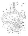
- FIG. 2 ais an exploded perspective view illustrating a patella array assembly in accordance with the present teachings
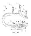
- FIG. 2 bis a perspective view of the patella array assembly of FIG. 2 a shown assembled
- FIG. 3is a fragmentary perspective view illustrating a patella resurfacing procedure
- FIG. 4is a fragmentary perspective view illustrating a patella tracking procedure in accordance with the present teachings
- FIG. 5is a fragmentary perspective view illustrating a patella array assembly being tracked as a leg is moved through a range of motion between flexion and extension during a surgical procedure in accordance with the present teachings;
- FIG. 6is a fragmentary perspective view illustrating a patella array assembly being aligned relative to an implanted femoral component in accordance with a patella tracking procedure of the present teachings
- FIG. 7is another fragmentary perspective view illustrating a patella array assembly being aligned relative to an implanted femoral component in accordance with a patella tracking procedure of the present teachings
- FIG. 8 ais an exploded fragmentary perspective view illustrating another patella array assembly in accordance with the present teachings.
- FIG. 8 bis a fragmentary perspective view illustrating the patella array assembly of FIG. 8 a shown engaging a patella;
- FIG. 8 cis a bottom view of the patella array assembly of FIG. 8 a;
- FIG. 9 ais a partial fragmentary perspective view illustrating another patella array assembly engaging a patella in accordance with the present teachings
- FIG. 9 bis a bottom view of the patella array assembly of FIG. 9 a;
- FIG. 10is a partial fragmentary perspective view illustrating another patella tracking procedure in accordance with the present teachings.
- FIG. 11is a partial fragmentary perspective view illustrating yet another patella tracking procedure in accordance with the present teachings.
- FIG. 1shows a perspective view of an operating room with a surgical navigation system 20 .
- a surgeon 21is aided by the surgical navigation system in performing knee arthroplasty, also known as knee replacement surgery, on a patient 22 shown lying on the operating table 24 .
- the surgical navigation system 20has a tracking system that locates arrays and tracks them in real-time.
- the surgical navigation systemincludes an optical locator 23 , which has two CCD (charge couple device) cameras 25 that detect the positions of the arrays in space by using triangulation methods.
- the relative location of the tracked arrays, including the patient's anatomy,can then be shown on a computer display (such as computer display 27 for instance) to assist the surgeon during the surgical procedure.
- a computer displaysuch as computer display 27 for instance
- the arrays that are typically usedinclude probe arrays, instrument arrays, reference arrays, and calibrator arrays.
- the operating roomincludes an imaging system such as a C-arm fluoroscope 26 with a fluoroscope display image 28 to show a real-time image of the patient's knee on a monitor 30 .
- the surgeon 21uses a surgical probe 32 to reference a point on the patient's knee, and the reference arrays 34 , 36 , which are attached to the patient's femur and tibia to provide known anatomic reference points so the surgical navigation system can compensate for leg movement.
- the relative location of the probe array 32 to the patient's tibiais then shown as reference numeral 40 on the computer display image 38 of the computer monitor 42 .
- the operating roomalso includes an instrument cart 45 having a tray 44 for holding a variety of surgical instruments and arrays 46 .
- the instrument cart 45 and the C-arm 26are typically draped in sterile covers 48 a , 48 b to eliminate contamination risks within the sterile field.
- the surgeryis performed within a sterile field, adhering to the principles of asepsis by all scrubbed persons in the operating room.
- the patient 22 , the surgeon 21 and the assisting clinician 50are prepared for the sterile field through appropriate scrubbing and clothing.
- the sterile fieldwill typically extend from the operating table 24 upward in the operating room.
- both the computer display image 38 and the fluoroscope display image 28are located outside of the sterile field.
- a representation of the patient's anatomycan be acquired with an imaging system, a virtual image, a morphed image, or a combination of imaging techniques.
- the imaging systemcan be any system capable of producing images that represent the patient's anatomy such as a fluoroscope producing x-ray two-dimensional images, computer tomography (CT) producing a three-dimensional image, magnetic resonance imaging (MRI) producing a three-dimensional image, ultrasound imaging producing a two-dimensional image, and the like.
- CTcomputer tomography
- MRImagnetic resonance imaging
- ultrasound imagingproducing a two-dimensional image
- a virtual image of the patient's anatomycan be created by defining anatomical points with the surgical navigation system 20 or by applying a statistical anatomical model.
- a morphed image of the patient's anatomycan be created by combining an image of the patient's anatomy with a data set, such as a virtual image of the patient's anatomy.
- Some imaging systemssuch as the C-arm fluoroscope 26 , can require calibration.
- the C-armcan be calibrated with a calibration grid that enables determination of fluoroscope projection parameters for different orientations of the C-arm to reduce distortion.
- a registration phantomcan also be used with a C-arm to coordinate images with the surgical navigation application program and improve scaling through the registration of the C-arm with the surgical navigation system.
- the tracking system of the present teachingscan be any system that can determine the three-dimensional location of devices carrying or incorporating markers that serve as tracking indicia. More particularly, the tracking system may be an active tracking system that has a collection of infrared light emitting diode (ILEDs) illuminators surrounding the position sensor lenses to flood a measurement field of view with infrared light. Alternatively, the system may be a passive tracking system, which incorporates retro-reflective markers that reflect infrared light back to the position sensor, and the system triangulates the real-time position (x, y, and z location) and orientation (rotation around x, y, and z axes).
- ILEDsinfrared light emitting diode
- the tracking systemmay be a hybrid tracking system that detects active and active wireless markers in addition to passive markers. Active marker based instruments enable automatic tool identification, program control of visible LEDs, and input via tool buttons.
- the tracking systemmay utilize electromagnetic tracking techniques. These systems locate and track devices and produce a real-time, three-dimensional video display of the surgical procedure by using electromagnetic field transmitters that generate a local magnetic field around the patient's anatomy.
- patella array assembly 60consists of a patella trial button/component 61 and an array component 70 having a frame 75 , array towers 74 and patella receiving disk 79 .
- the frameis substantially shaped and sized to accommodate a patella that is placed therein.
- the frameis C-shaped thereby creating a clip-like structure, which is designed to accommodate the patella during a surgical procedure.
- the patella trial button 61has one or more studs or prongs (e.g., rounded studs 62 and slotted stud 64 ), which extend upwardly from a bottom surface 63 of the button. While not required, in certain embodiments the studs 62 and 64 can be substantially the same height. As will be explained below, the studs 62 and 64 are configured to interface with holes that are drilled into a patella during a surgical procedure.
- the slotted stud 64includes two halves ( 64 a and 64 b ), both of which bias slightly outwardly so that when the stud is inserted into the drilled patella hole, the halves 64 a and 64 b press against the inner surface of the hole to create a secure fit. While this embodiment shows a configuration having three studs, it should be appreciated that other configurations may also be used as desired without straying from the present teachings. As such, the present teachings are not intended to be limited herein.
- the patella trial button 61also has a flanged top surface 78 and a sidewall 68 a , which together define a recessed cavity 68 b for receiving the patella receiving disk 79 during assembly. More particularly, during assembly, the patella receiving disk 79 is placed inside the recessed cavity 68 b such that top surfaces 73 and 78 align to create a substantially flat resting surface 77 , as shown in FIG. 2 b , which is adapted to support the patella during the surgical procedure. To achieve this aligned orientation, a portion 66 of the trial button's flanged top surface 78 is removed to receive a portion 70 b of the array assembly's frame 75 .
- the array towers 74 of the array component 70are spaced apart by the frame 75 so that the array markers 76 can be independently recognized and tracked by the CCD cameras 25 of the optical locator 23 during a surgical procedure.
- the array component 70also has a series of holes (e.g., round holes 72 and oval hole 71 ), which are used to assemble the patella array assembly 60 . More particularly, during assembly, the rounded studs 62 are advanced through the round holes 72 along line 72 a , while the slotted stud 64 is advanced through the oval hole 71 along line 71 a . It should be understood and appreciated herein that the diameter of the studs is slightly less than that of the holes so that the studs are able to fit through the holes and achieve a friction fit thereto.
- a portion of the slotted stud 64protrudes out of the oval hole 71 of the array component 70 and biases slightly outwardly as described above.
- the studs 62 and 64have chamfered edges 67 and 65 , respectively, which facilitate the array assembly 60 to be guided into pre-drilled holes of the patella as the trial button 61 is attached to the patella.
- the transition from a flat surface to an inflection point 69creates the resting surface 77 for the patella, as well as serves to stabilize the patella as the surgeon manipulates the patella during the surgical procedure.
- FIG. 3illustrates a surgeon preparing to resurface a patient's patella prior to attaching a trial button
- the surgeonplaces a cutting blade 118 of a cutting tool 116 through a cutting guide 114 associated with the clamping jaws 112 and resects the surface of the patella 108 that is natively in contact with the femur 102 and the tibia 104 . It should be noted that in other embodiments the surgeon could alternatively cut or resect the patella surface directly and without the use of a cutting guide. As such, the present teachings are not intended to be limited.
- a drill guide template(not shown) is placed over the resurfaced patella and is used for drilling holes into the surface of the patella 108 .
- the spatial orientation of the holes on the drill guide templateare arranged such that they substantially correspond with or match the orientation of the studs 62 and 64 on the trial button 61 .
- the trial buttonis secured to the patella 108 so that its relative position can be tracked by the navigation system. With respect to the manner by which the assembly is secured to the patella, such assembly should be secured so that the array markers 76 have a clear optical path to the optical locator 23 and its CCD cameras 25 .
- the tracking systemlocates and tracks the patella array assembly in real-time (see the optical path/measurement field of the tracking system represented by dashed lines 111 ).
- the cameras 25 of the optical locator 23detect the position of the patella array assembly 60 in space by using triangulation methods, which reference the position of the array assembly as it moves with respect to the rigid reference arrays 36 a and 36 b , which are fixably attached to the tibia and femur of the patient, respectively.
- the relative location of the patella array assembly 60 with respect to the patient's leg 120may then be shown as a real-time image on a computer display during the surgical procedure.
- the surgeon 21To track the position of the patella 108 with respect to the femur 102 and the tibia 104 , the surgeon 21 must next register the patella 108 with the navigation system 20 by collecting various points or bony landmarks on the patella 108 . More particularly, in accordance with certain aspects of the present teachings, the surgeon intra-operatively acquires individual surface landmarks of the patient's anatomy with a surgical probe (or other similar instrument) as the probe is detected and tracked by the navigation system. By acquiring these landmarks and registering them with the navigation system's computer, a surgeon can accurately navigate a biomedical implant to an intra-operatively planned position, as well as gather important surgical information, such as gap analysis data, resection plane details and bone and/or surgical component alignment angles.
- bony landmarksare visible points or locations on a patient's anatomy, which are identifiable by referencing known locations on the surface of the bone.
- known bony landmarks on the femurinclude, but are not limited to, the medial and lateral condyles, the medial and lateral epicondyles, the medial and lateral posterior condyles, and the anterior cortex.
- Similar bony landmarksare also found on other bones, such as the tibia, fibula, patella and pelvis, for instance.
- the surgeon 21then tracks the patella trial button 61 as it articulates or moves with respect to the femur and tibia by tracking the relative movement of the array assembly 60 .
- trial componentsare attached to the patient's bones, particularly as these trial components can be independently moved, manipulated and/or fine adjusted as needed before the final implants are secured to the patient's anatomy.
- the permanent patella implantupon removal of the patella trial button/component 61 from the patella, the permanent patella implant can be fitted to the patella using the same holes and engagement location as was used by the trial component. Since the same series of patella holes are used for both the trial and permanent patella components, the surgical procedure can be performed less invasively, thereby improving the recovery time of the patient undergoing the operative procedure.
- FIG. 5a patella array assembly 60 being tracked in accordance with the present teachings is depicted.
- the surgeon 21manipulates the patient's leg 120 from a flexion position to an extension position (as indicated by solid and phantom lines), while the patella 108 is engaged by the patella array assembly 60 .
- the surgeonmoves the leg in the direction indicated by arrow 123 between the flexion and extension positions to determine if the leg is properly traveling along a desired axial path as defined by the leg's mechanical axes. If the leg is not traveling this intended path, then the natural joint function of the leg will not be achieved and the life of the implanted components could be lessened or negatively impacted.
- the mechanical axis of the femur(which connects the center of a patient's hip with the center of the patient's knee) and the mechanical axis of the tibia (which connects the center of the patient's knee with the center of the patient's ankle) should be determined.
- These axesare determined because the resections performed prior to installing the femoral and tibial components must be aligned in accordance with these respective axes.
- the exact positions of the resection surfaces on the femur and tibiaare crucial if the knee prosthetics are to have long working lives.
- the surgeonmust establish the standard bearing surfaces of the resection planes on the femur and tibia according to geometrical specifications of the knee prosthetics while taking into account their respective mechanical axes. In some cases, pathological displacements must also be corrected and allowances must be made for the position and action of the ligaments and muscles that are present in the leg.
- the surgeontracks the leg as it is moved through a range of motion. This tracked movement tells the surgeon if the position of one or more of the surgical components should be adjusted, particularly if the leg is not traveling its intended path when moved through flexion and extension.
- the surgeontouches a surgical probe against the surface of the femur and tibia at two individual locations that together form a line defining the respective femoral and tibial mechanical axes.
- surgical probesinclude markers, which are identified and tracked by cameras of an optical locator.
- the tracking systemlocates and tracks the markers in real-time and detects their positions in space by using triangulation methods. The relative locations on the femur and tibia are then shown on a surgical plan image.
- the tracking systemdetects the location of the surgical probe as it is positioned relative to the femur and the tibia by referencing the position of the markers as they move with respect to reference arrays (e.g., 36 a , 36 b ), which are fixably attached to the tibia and femur.
- reference arrayse.g., 36 a , 36 b
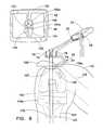
- the surgeon 21observes this movement on a computer monitor 42 , which displays a computer image 38 of the leg, including the femur 102 , the tibia 104 and the patella 108 , as well as the femoral component 102 a , the tibial component 104 a and a polyethylene component 103 .
- the femoral-tibial mechanical axis 122is also shown on the computer image, which illustrates the path the leg is intended to travel when articulated from flexion to extension. As can be seen in this illustrative embodiment, when the surgeon moves the leg between flexion and extension, the leg is not traveling along this intended path, but instead is traveling along a slightly different path, which is shown here as dashed line 125 .
- This flawed leg movementinforms the surgeon that the implanted components (i.e., the patella trial button/component 61 , the femoral component 102 a , the tibial component 104 a and the polyethylene component 103 ) may not be properly aligned, angled and/or sized with respect to one another. Such misalignment can be problematic, particularly as it is generally understood that misaligned components can cause premature failure of the implants, as well as chronic postoperative pain and discomfort for the patient.
- the implanted componentsi.e., the patella trial button/component 61 , the femoral component 102 a , the tibial component 104 a and the polyethylene component 103 .
- the surgeoncan correct this misalignment by adjusting the lateral, medial and/or angular position of one or more of the temporarily placed trial surgical components.
- FIG. 5illustrates the patient's leg in a flexion position. More particularly, as explained above, when the surgeon moves the leg between flexion and extension, the leg is not traveling along the femoral-tibial mechanical axis 122 , but instead is traveling along a slightly different path 125 or axis. As such, the implanted components may not be properly aligned, angled and/or sized with respect to one another.
- a bottom portion 107 of the patella trial button 61which is attached to the resurfaced portion of the patella 108 , is slightly offset or misaligned from a corresponding top portion 105 of the femoral component 102 a to which it is supposed to align.
- This slight offset between the prosthetic componentscauses the leg 120 to travel about an axial path 125 that is slightly off center from the intended femoral-tibial mechanical axis 122 while the leg is moved from flexion to extension.
- the surgeonknows that the lateral, medial and/or angular position of the temporarily placed trial surgical components is misaligned thereby causing flawed movement of the leg through extension.
- the surgeoncan correct this misalignment by adjusting the positioning and/or sizing of one or more of the surgical components, such as the femoral component, which is configured to articulate against the surface of the patella trial button 61 during movement of the leg 120 .
- the surgeonis able to identify the location at which the patella implant should be installed to achieve appropriate flexion and extension of the leg through a range of motion.
- the leg 120is once again taken through a range of motion (flexion/extension) to determine whether the leg now travels the proper femoral-tibial mechanical axis 122 .
- the legis now substantially following the correct femoral-tibial mechanical axis 122 .
- a spring-loaded patella clamping mechanism 200is illustrated in FIGS. 8 a - 8 c .
- a quick connect device 202such as a female J-quick connect device
- This quick connect device 202is configured to interface with a removable and interchangeable array assembly 204 , the array assembly being connectable to the quick connect device by sliding a pin 205 of the array assembly 204 into a corresponding groove 201 of the quick connect device 202 .
- another quick connect device 221such as a T-shaped quick connect, is provided, which has a post 224 having a flanged lip 222 .
- a patella trial button 206which has a slot 209 having key openings 208 and 210 .
- a patella 108is slid into the spring-loaded clamp 200 while the patella tendons 100 are substantially unrestricted. Due to the compressive force of the spring-loaded clamp 200 , the patella 108 is securely constrained and thereby discouraged from moving relative to the spring-loaded clamp 200 .
- the clampis connected to the patella trial button 206 by sliding the flanged lip 222 of the post 224 into key opening 210 and moving the post 224 horizontally until it enters the second narrower key opening 208 .
- This configurationallows the patella trial button 206 to slide to a locked position, which is then centrally located on the bottom side of the spring-loaded clamp 200 .
- the pin 205 of the array assembly 204is slid into the corresponding groove 201 of the quick connect device 202 and rotated until locked into place. While this illustrative embodiment shows a quick connect attachment means being used to attach the array assembly 204 to the spring-loaded clamp 200 , it should be understood that in other embodiments, the array assembly 204 may be “pre-installed” onto the spring-loaded clamp whereby no additional attachment means is required after the clamp engages the patella. It should also be understood and appreciated that any attachment means known within the art may be used to secure the array assembly 204 and/or the patella trial button 206 to the spring-loaded clamp 200 .
- Such attachment meansinclude, but are not limited to, welding, fusing, molding, gluing, threading, snap-connections, quick connect, quick disconnect connections and the like.
- quick connect array assembliesSee U.S. patent application Ser. No. 11/299,886, entitled “IMAGE GUIDED TRACKING ARRAY AND METHOD,” filed Dec. 12, 2005, which is incorporated by reference herein in its entirety.
- FIGS. 8 a - cadvantageously provides drill guide holes 220 so that the surgeon 21 can drill holes into the patella 108 after the components have been appropriately aligned as desired.
- the surgeoncan remove the patella trial button 206 and drill holes into the patella 108 through the drill guide holes 220 .
- the surgeoncan attach a permanent patella button component to the patella and proceed with the remainder of the surgery.
- the patellacan be resected either before or after the spring-loaded clamp 200 is attached to the patella 108 . This flexibility is possible particularly because the spring-loaded clamp can be temporarily, as opposed to permanently, attached to the patella. As such, the patella does not need to be resected or resurfaced until the prosthetic patella component is ready to be permanently attached.
- the thickness of the spring-loaded clamp 200For purposes of tracking a leg (and its associated components) through a range of motion, it is important to take into account the thickness of the spring-loaded clamp 200 .
- the spring-loaded clampAs the spring-loaded clamp is positioned between the patella 108 and the patella trial button 206 , it contributes to the distance between the patella surface and the patella trial button.
- the permanent patella trial button installed to the patellamust account for this loss in thickness to thereby achieve the same tracked range of motion registered with the navigation system.
- One way to account for this thickness differentialis to have a permanent patella button that is slightly thicker than the temporary patella button.
- the navigation systemcan be programmed to recognize this thickness differential and consider this information when tracking the leg through the range of motion.
- FIG. 8 billustrates a patella 108 placed inside the spring-loaded clamp 200 having an array assembly 204 attached thereto.
- the amount of force applied to the patella 108 once slid into the spring-loaded clampis directly proportional to the resurfaced size of the patella and the equivalent spring constant of the spring-loaded clamp 200 .
- the applied forceshould be large enough to appropriately secure the patella 108 in place yet not inflict damage to the patella.
- FIG. 8 cis a bottom view of the spring-loaded clamp 200 illustrating drill guide holes 220 , as well as the post 224 and its associated flanged lip 222 .
- FIGS. 9 a - 9 ba crank-type clamping mechanism is illustrated in FIGS. 9 a - 9 b .
- the removable and interchangeable array assembly 204connects to a crank-loaded clamp 240 via a channel quick connect 202 .
- a side plate 254 of the clamp 240moves horizontally by turning a crank 242 , which causes a screw 256 to turn inside and outside of welded nuts 260 , thereby forcing the side plate to move along slot tracks 244 and 246 .
- the side plate 254begins its movement in the slot tracks 244 and 246 by inserting the post 248 in the tracks, which on one end, reaches the edge of the top plate 250 .
- a second side plate 252is fixed into place such that when the turning crank 242 is actuated, the side plate 252 does not move.
- the slot feature illustrated in FIG. 9 aoperates in a similar fashion as the slot feature in FIG. 8 a .
- the crank clamps 258make contact with the patella 108 and secure it into place so that the surgeon 21 can manipulate it without relative movement between the patella 108 and the crank clamps 258 .
- This embodimentadvantageously allows the surgeon 21 to decide the amount of force that should be exerted on the patella 108 by turning the crank 242 .
- electronic displayssuch as LEDs and LCDs may be mountable to the crank-loaded clamp 240 to display the amount of force the surgeon 21 exerts on the patella 108 .
- the surgeon 21may use this feedback information along with bone density information to determine the appropriate amount of force needed to secure to the patella without causing damage.
- the crank-loaded clampmay be equipped with a pressure sensitive material or film, such as FlexiForce® Load/Force Sensors and System manufactured by Tekscan Incorporated, 307 West First Street, South Boston, Mass. 02127-1309. This film allows the pressure encountered by the crank clamps 258 , when they respectively contact the patella 108 during the engagement process, to be determined. More particularly, when either one of the crank clamps 258 encounter the patella 108 , that clamp will meet a resistance force to sideways movement.
- the resistancecan be detected by a transmitter device and translated into a pressure reading to be transmitted to the computer system via a communication link.
- the transmittermay be an infrared transmitter device capable of establishing a communication link with the navigation system. Infrared transmission devices are known in the art and do not need to be discussed in further detail here.
- FIG. 9 bis a bottom view of the clamping mechanism 240 .
- the side plateis shown fastened to the screw 256 by a welded locking nut 260 .
- FIGS. 9 a and 9 bdo not show an illustration of a patella trial button (e.g., patella trial button 61 , for instance) attached to the patella 108
- a patella trial buttoncan be used in conjunction with this illustrative embodiment, particularly to assist with holding the crank-loaded clamp 240 in engagement with the patella 108 .
- the present teachingsare not intended to be limited herein.
- a surgeonuses a hand-held probe array 300 to locate the femoral-tibial mechanical axis 122 . More particularly, the surgeon determines the femoral-tibial mechanical axis 122 by touching/acquiring the surgical probe array 300 against the surface of the femur and tibia at two individual locations that together form a line defining the respective femoral and tibial mechanical axes.
- the surgical probe array 300includes markers 76 , which are identified and tracked by cameras 25 of the optical locator 23 .
- the tracking systemlocates and tracks the markers 76 in real-time and detects their position in space by using triangulation methods. To accomplish this, the tracking system detects the location of the surgical probe array 300 as it is positioned relative to the femur 102 and the tibia 104 by referencing the position of the markers 76 as they move with respect to the reference arrays 36 b and 36 a , which are fixably attached to the femur and tibia, respectively.
- a representationis then shown as a computer display image 38 on the computer monitor 42 for use by the surgeon during the surgical procedure.
- the surgeoncan hold the tip of the probe array 300 against the patella 108 at a center point and move the leg through a range of motion between flexion and extension to evaluate movement of the leg with respect to the femoral-tibial mechanical axis 122 .
- the computer display image 38 on the computer monitor 42displays the actual axial path 125 the leg is moving with respect to the femoral-tibial axis 122 .
- the surgeon 21can decide whether further alignment is needed. For instance, the surgeon can correct a misalignment by adjusting the positioning of one or more of the surgical components, such as the femoral component, which is configured to articulate against the surface of the patella trial button during movement of the leg.
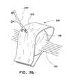
- a probe array guide 322is affixed to the patella 108 along the femoral-tibial axis 122 . More particularly, the surgeon determines the femoral-tibial mechanical axis 122 by touching/acquiring the surgical probe array 324 against the surface of the femur and tibia at two individual locations that together form a line defining the respective femoral and tibial mechanical axes.
- the surgical probe array 324includes markers 76 , which are identified and tracked by cameras 25 of the optical locator 23 .
- the tracking systemlocates and tracks the markers 76 in real-time and detects their position in space by using triangulation methods. To accomplish this, the tracking system detects the location of the surgical probe array 324 as it is positioned relative to the femur 102 and the tibia 104 by referencing the position of the markers 76 as they move with respect to the reference arrays 36 b and 36 a , which are fixably attached to the femur and tibia, respectively.
- a representationis then shown as a computer display image 38 on the computer monitor 42 for use by the surgeon during the surgical procedure.
- the surgeondrills the probe array guide 322 into the patella at a center point along the femoral-tibial mechanical axis 122 .
- the probe array guidecan be used to hold the tip of the probe array 324 against the patella 108 as the leg is moved between flexion and extension and thereby indicating how the leg is tracking with respect to the femoral-tibial mechanical axis 122 .
- the computer display image 38 on the computer monitor 42shows the actual axial path 125 the leg is moving with respect to the femoral-tibial axis 122 .
- the surgeon 21can decide whether further alignment is needed. For instance, the surgeon can correct a misalignment by adjusting the positioning of one or more of the surgical components, such as the femoral component, which is configured to articulate against the surface of the patella trial button during movement of the leg.
- the surgical componentssuch as the femoral component
Landscapes
- Health & Medical Sciences (AREA)
- Surgery (AREA)
- Life Sciences & Earth Sciences (AREA)
- Engineering & Computer Science (AREA)
- Heart & Thoracic Surgery (AREA)
- Animal Behavior & Ethology (AREA)
- Veterinary Medicine (AREA)
- Biomedical Technology (AREA)
- Nuclear Medicine, Radiotherapy & Molecular Imaging (AREA)
- Medical Informatics (AREA)
- Molecular Biology (AREA)
- Public Health (AREA)
- General Health & Medical Sciences (AREA)
- Pathology (AREA)
- Oral & Maxillofacial Surgery (AREA)
- Robotics (AREA)
- Surgical Instruments (AREA)
- Prostheses (AREA)
Abstract
Description
Claims (7)
Priority Applications (1)
| Application Number | Priority Date | Filing Date | Title |
|---|---|---|---|
| US12/356,963US8571637B2 (en) | 2008-01-21 | 2009-01-21 | Patella tracking method and apparatus for use in surgical navigation |
Applications Claiming Priority (2)
| Application Number | Priority Date | Filing Date | Title |
|---|---|---|---|
| US2237408P | 2008-01-21 | 2008-01-21 | |
| US12/356,963US8571637B2 (en) | 2008-01-21 | 2009-01-21 | Patella tracking method and apparatus for use in surgical navigation |
Related Child Applications (1)
| Application Number | Title | Priority Date | Filing Date |
|---|---|---|---|
| US14/099,275Continuation-In-PartUS9078337B2 (en) | 2011-06-24 | 2013-12-06 | Plasma-generating device |
Publications (2)
| Publication Number | Publication Date |
|---|---|
| US20090183740A1 US20090183740A1 (en) | 2009-07-23 |
| US8571637B2true US8571637B2 (en) | 2013-10-29 |
Family
ID=40875455
Family Applications (1)
| Application Number | Title | Priority Date | Filing Date |
|---|---|---|---|
| US12/356,963Active2032-05-17US8571637B2 (en) | 2008-01-21 | 2009-01-21 | Patella tracking method and apparatus for use in surgical navigation |
Country Status (1)
| Country | Link |
|---|---|
| US (1) | US8571637B2 (en) |
Cited By (17)
| Publication number | Priority date | Publication date | Assignee | Title |
|---|---|---|---|---|
| US20150128433A1 (en)* | 2013-11-11 | 2015-05-14 | General Electric Company | Bucket tip shroud measurement fixture and method of measuring bucket tip shroud orientation |
| US20160331479A1 (en)* | 2012-06-21 | 2016-11-17 | Globus Medical, Inc. | Surgical tool systems and methods |
| WO2017189719A1 (en) | 2016-04-27 | 2017-11-02 | Biomet Manufacturing, Llc | Surgical system having assisted navigation |
| WO2017218928A1 (en) | 2016-06-16 | 2017-12-21 | Pierre Couture | Soft tissue balancing in articular surgery |
| US20180014809A1 (en)* | 2016-07-13 | 2018-01-18 | Carestream Health, Inc. | Calibration phantom |
| US10314599B2 (en) | 2016-03-31 | 2019-06-11 | Howmedica Osteonics Corp. | Navigated patella clamp |
| US10463434B2 (en) | 2014-09-24 | 2019-11-05 | 7D Surgical Inc. | Tracking marker support structure and surface registration methods employing the same for performing navigated surgical procedures |
| US10588696B2 (en) | 2016-08-03 | 2020-03-17 | Mako Surgical Corp. | Patella implant planning |
| RU199990U1 (en)* | 2020-07-03 | 2020-10-01 | Общество с ограниченной ответственностью "МОТУС" | Device for determining the stiffness of the patellar ligamentous apparatus |
| US10973580B2 (en) | 2015-03-26 | 2021-04-13 | Biomet Manufacturing, Llc | Method and system for planning and performing arthroplasty procedures using motion-capture data |
| US11143499B2 (en)* | 2018-09-18 | 2021-10-12 | Electronics And Telecommunications Research Institute | Three-dimensional information generating device and method capable of self-calibration |
| US11229489B2 (en) | 2016-06-16 | 2022-01-25 | Zimmer, Inc. | Soft tissue balancing in articular surgery |
| US11510737B2 (en) | 2018-06-21 | 2022-11-29 | Mako Surgical Corp. | Patella tracking |
| US20220387121A1 (en)* | 2021-06-07 | 2022-12-08 | Orthosoft Ulc | Instruments for robotic knee revision |
| USD995790S1 (en) | 2020-03-30 | 2023-08-15 | Depuy Ireland Unlimited Company | Robotic surgical tool |
| US12004816B2 (en) | 2020-03-30 | 2024-06-11 | Depuy Ireland Unlimited Company | Robotic surgical apparatus with positioning guide |
| US12042944B2 (en) | 2020-03-30 | 2024-07-23 | Depuy Ireland Unlimited Company | Robotic surgical system with graphical user interface |
Families Citing this family (21)
| Publication number | Priority date | Publication date | Assignee | Title |
|---|---|---|---|---|
| US8160743B2 (en)* | 2005-08-16 | 2012-04-17 | Brainlab Ag | Anthropomorphic medical robot arm with movement restrictions |
| US11911117B2 (en) | 2011-06-27 | 2024-02-27 | Board Of Regents Of The University Of Nebraska | On-board tool tracking system and methods of computer assisted surgery |
| US9498231B2 (en) | 2011-06-27 | 2016-11-22 | Board Of Regents Of The University Of Nebraska | On-board tool tracking system and methods of computer assisted surgery |
| CN103764061B (en) | 2011-06-27 | 2017-03-08 | 内布拉斯加大学评议会 | On Tool Tracking System and Computer Assisted Surgery Method |
| US9993273B2 (en) | 2013-01-16 | 2018-06-12 | Mako Surgical Corp. | Bone plate and tracking device using a bone plate for attaching to a patient's anatomy |
| EP4309613B1 (en) | 2013-01-16 | 2025-07-23 | Stryker Corporation | Navigation systems for indicating line-of-sight errors |
| US10335239B2 (en)* | 2013-02-20 | 2019-07-02 | Brainlab Ag | Disposable reflective marker |
| AU2014228789A1 (en)* | 2013-03-15 | 2015-10-29 | Board Of Regents Of The University Of Nebraska | On-board tool tracking system and methods of computer assisted surgery |
| US10105149B2 (en) | 2013-03-15 | 2018-10-23 | Board Of Regents Of The University Of Nebraska | On-board tool tracking system and methods of computer assisted surgery |
| US11292924B2 (en)* | 2014-04-08 | 2022-04-05 | Silcotek Corp. | Thermal chemical vapor deposition coated article and process |
| AT14453U1 (en)* | 2014-04-22 | 2015-11-15 | Hermann Maderbacher | Multifunctional attachment base for a patella reference unit |
| GB2546055B (en)* | 2014-10-14 | 2020-05-20 | Synaptive Medical Barbados Inc | Patient reference tool |
| KR102477470B1 (en)* | 2014-11-21 | 2022-12-13 | 씽크 써지컬, 인크. | Visible light communication system for transmitting data between visual tracking systems and tracking markers |
| WO2017028916A1 (en)* | 2015-08-19 | 2017-02-23 | Brainlab Ag | Reference array holder |
| US10537395B2 (en) | 2016-05-26 | 2020-01-21 | MAKO Surgical Group | Navigation tracker with kinematic connector assembly |
| LU93104B1 (en)* | 2016-06-13 | 2018-01-23 | Scopis Gmbh | Attachment of tracking elements to surgical instruments |
| WO2018106947A1 (en)* | 2016-12-09 | 2018-06-14 | Stc. Unm | Feeding tube visualization |
| WO2020033568A2 (en)* | 2018-08-07 | 2020-02-13 | Smith & Nephew Inc. | Patella tracking method and system |
| US10772617B2 (en)* | 2018-11-15 | 2020-09-15 | Little Engine, LLC | Knee flexion and extension gap tensioning and measuring apparatus |
| GB202007877D0 (en) | 2020-05-27 | 2020-07-08 | Naybour John | A trial patella component kit |
| CN113288559B (en)* | 2021-06-01 | 2023-07-07 | 上海开为医药科技有限公司 | Knee fixing bracket |
Citations (207)
| Publication number | Priority date | Publication date | Assignee | Title |
|---|---|---|---|---|
| US4341220A (en) | 1979-04-13 | 1982-07-27 | Pfizer Inc. | Stereotactic surgery apparatus and method |
| US4360028A (en) | 1980-01-14 | 1982-11-23 | Barbier Jean Y | Cranial insertion of surgical needle utilizing computer-assisted tomography |
| US4583538A (en) | 1984-05-04 | 1986-04-22 | Onik Gary M | Method and apparatus for stereotaxic placement of probes in the body utilizing CT scanner localization |
| US4791934A (en) | 1986-08-07 | 1988-12-20 | Picker International, Inc. | Computer tomography assisted stereotactic surgery system and method |
| US4945914A (en) | 1987-11-10 | 1990-08-07 | Allen George S | Method and apparatus for providing related images over time of a portion of the anatomy using at least four fiducial implants |
| EP0427358A1 (en) | 1989-11-08 | 1991-05-15 | George S. Allen | Mechanical arm for and interactive image-guided surgical system |
| US5086401A (en) | 1990-05-11 | 1992-02-04 | International Business Machines Corporation | Image-directed robotic system for precise robotic surgery including redundant consistency checking |
| US5222499A (en) | 1989-11-15 | 1993-06-29 | Allen George S | Method and apparatus for imaging the anatomy |
| US5309913A (en) | 1992-11-30 | 1994-05-10 | The Cleveland Clinic Foundation | Frameless stereotaxy system |
| WO1994017733A1 (en) | 1993-02-12 | 1994-08-18 | Mccrory, Jennifer, J. | Fiducial marker |
| US5383454A (en) | 1990-10-19 | 1995-01-24 | St. Louis University | System for indicating the position of a surgical probe within a head on an image of the head |
| US5389101A (en) | 1992-04-21 | 1995-02-14 | University Of Utah | Apparatus and method for photogrammetric surgical localization |
| EP0649117A2 (en) | 1993-10-15 | 1995-04-19 | George S. Allen | Method for providing medical images |
| WO1995015714A1 (en) | 1993-12-08 | 1995-06-15 | Fitzpatrick J Michael | Localization cap for fiducial markers |
| US5517990A (en) | 1992-11-30 | 1996-05-21 | The Cleveland Clinic Foundation | Stereotaxy wand and tool guide |
| US5603318A (en) | 1992-04-21 | 1997-02-18 | University Of Utah Research Foundation | Apparatus and method for photogrammetric surgical localization |
| US5628315A (en) | 1994-09-15 | 1997-05-13 | Brainlab Med. Computersysteme Gmbh | Device for detecting the position of radiation target points |
| US5638819A (en) | 1995-08-29 | 1997-06-17 | Manwaring; Kim H. | Method and apparatus for guiding an instrument to a target |
| US5682890A (en) | 1995-01-26 | 1997-11-04 | Picker International, Inc. | Magnetic resonance stereotactic surgery with exoskeleton tissue stabilization |
| US5682886A (en) | 1995-12-26 | 1997-11-04 | Musculographics Inc | Computer-assisted surgical system |
| USD387427S (en) | 1996-02-12 | 1997-12-09 | Surgical Navigation Technologies, Inc. | Ventriculostomy probe |
| US5732703A (en) | 1992-11-30 | 1998-03-31 | The Cleveland Clinic Foundation | Stereotaxy wand and tool guide |
| EP0832609A2 (en) | 1996-09-30 | 1998-04-01 | Picker International, Inc. | Position tracking |
| US5769861A (en) | 1995-09-28 | 1998-06-23 | Brainlab Med. Computersysteme Gmbh | Method and devices for localizing an instrument |
| US5772594A (en) | 1995-10-17 | 1998-06-30 | Barrick; Earl F. | Fluoroscopic image guided orthopaedic surgery system with intraoperative registration |
| US5799055A (en) | 1996-05-15 | 1998-08-25 | Northwestern University | Apparatus and method for planning a stereotactic surgical procedure using coordinated fluoroscopy |
| EP0904735A2 (en) | 1997-09-26 | 1999-03-31 | Picker International, Inc. | Tool calibration |
| US5891034A (en) | 1990-10-19 | 1999-04-06 | St. Louis University | System for indicating the position of a surgical probe within a head on an image of the head |
| US5902239A (en) | 1996-10-30 | 1999-05-11 | U.S. Philips Corporation | Image guided surgery system including a unit for transforming patient positions to image positions |
| US5967982A (en) | 1997-12-09 | 1999-10-19 | The Cleveland Clinic Foundation | Non-invasive spine and bone registration for frameless stereotaxy |
| US5999837A (en) | 1997-09-26 | 1999-12-07 | Picker International, Inc. | Localizing and orienting probe for view devices |
| US6005548A (en) | 1996-08-14 | 1999-12-21 | Latypov; Nurakhmed Nurislamovich | Method for tracking and displaying user's spatial position and orientation, a method for representing virtual reality for a user, and systems of embodiment of such methods |
| US6021343A (en) | 1997-11-20 | 2000-02-01 | Surgical Navigation Technologies | Image guided awl/tap/screwdriver |
| USD420132S (en) | 1997-11-03 | 2000-02-01 | Surgical Navigation Technologies | Drill guide |
| USD422706S (en) | 1997-04-30 | 2000-04-11 | Surgical Navigation Technologies | Biopsy guide tube |
| US6050724A (en) | 1997-01-31 | 2000-04-18 | U. S. Philips Corporation | Method of and device for position detection in X-ray imaging |
| US6096050A (en) | 1997-09-19 | 2000-08-01 | Surgical Navigation Specialist Inc. | Method and apparatus for correlating a body with an image of the body |
| US6122541A (en) | 1995-05-04 | 2000-09-19 | Radionics, Inc. | Head band for frameless stereotactic registration |
| US6161033A (en) | 1998-04-17 | 2000-12-12 | U.S. Philips Corporation | Image guided surgery system |
| US6166746A (en) | 1994-07-21 | 2000-12-26 | Matsushita Electric Industrial Co., Ltd. | Three-dimensional image processing apparatus for jointed objects |
| US6167292A (en) | 1998-06-09 | 2000-12-26 | Integrated Surgical Systems Sa | Registering method and apparatus for robotic surgery, and a registering device constituting an application thereof |
| US6167145A (en) | 1996-03-29 | 2000-12-26 | Surgical Navigation Technologies, Inc. | Bone navigation system |
| US6178345B1 (en) | 1998-06-30 | 2001-01-23 | Brainlab Med. Computersysteme Gmbh | Method for detecting the exact contour of targeted treatment areas, in particular, the external contour |
| US6187018B1 (en) | 1999-10-27 | 2001-02-13 | Z-Kat, Inc. | Auto positioner |
| US6190395B1 (en) | 1999-04-22 | 2001-02-20 | Surgical Navigation Technologies, Inc. | Image guided universal instrument adapter and method for use with computer-assisted image guided surgery |
| US6205411B1 (en) | 1997-02-21 | 2001-03-20 | Carnegie Mellon University | Computer-assisted surgery planner and intra-operative guidance system |
| US6236875B1 (en) | 1994-10-07 | 2001-05-22 | Surgical Navigation Technologies | Surgical navigation systems including reference and localization frames |
| US6235038B1 (en) | 1999-10-28 | 2001-05-22 | Medtronic Surgical Navigation Technologies | System for translation of electromagnetic and optical localization systems |
| US20010007918A1 (en) | 2000-01-12 | 2001-07-12 | Brainlab Ag | Intraoperative navigation updating |
| US6285902B1 (en) | 1999-02-10 | 2001-09-04 | Surgical Insights, Inc. | Computer assisted targeting device for use in orthopaedic surgery |
| US20010027271A1 (en) | 1998-04-21 | 2001-10-04 | Franck Joel I. | Instrument guidance for stereotactic surgery |
| US6306126B1 (en) | 1998-09-18 | 2001-10-23 | Stryker Leibinger Gmbh & Co Kg | Calibrating device |
| US20010051881A1 (en) | 1999-12-22 | 2001-12-13 | Aaron G. Filler | System, method and article of manufacture for managing a medical services network |
| US6381485B1 (en) | 1999-10-28 | 2002-04-30 | Surgical Navigation Technologies, Inc. | Registration of human anatomy integrated for electromagnetic localization |
| US6379302B1 (en) | 1999-10-28 | 2002-04-30 | Surgical Navigation Technologies Inc. | Navigation information overlay onto ultrasound imagery |
| WO2002035454A1 (en) | 2000-09-25 | 2002-05-02 | Z-Kat, Inc. | Fluoroscopic registration artifact with optical and/or magnetic markers |
| US20020077540A1 (en) | 2000-11-17 | 2002-06-20 | Kienzle Thomas C. | Enhanced graphic features for computer assisted surgery system |
| US20020095081A1 (en) | 1995-09-28 | 2002-07-18 | Brainlab Med. Computersysteme Gmbh | Neuro-navigation system |
| US6424856B1 (en) | 1998-06-30 | 2002-07-23 | Brainlab Ag | Method for the localization of targeted treatment areas in soft body parts |
| EP1226788A1 (en) | 2001-01-25 | 2002-07-31 | Finsbury (Development) Limited | Computer-assisted knee arthroplasty system |
| US6428547B1 (en) | 1999-11-25 | 2002-08-06 | Brainlab Ag | Detection of the shape of treatment devices |
| US6434507B1 (en) | 1997-09-05 | 2002-08-13 | Surgical Navigation Technologies, Inc. | Medical instrument and method for use with computer-assisted image guided surgery |
| US6434415B1 (en) | 1990-10-19 | 2002-08-13 | St. Louis University | System for use in displaying images of a body part |
| WO2002062248A1 (en) | 2001-02-06 | 2002-08-15 | Cedara Software Corp. | Computer-assisted surgical positioning method and system |
| WO2002067783A2 (en) | 2001-02-27 | 2002-09-06 | Smith & Nephew, Inc. | Total knee arthroplasty systems and processes |
| US20020151894A1 (en) | 1997-12-12 | 2002-10-17 | Tony Melkent | Image guided spinal surgery guide, system, and method for use thereof |
| US6470207B1 (en) | 1999-03-23 | 2002-10-22 | Surgical Navigation Technologies, Inc. | Navigational guidance via computer-assisted fluoroscopic imaging |
| US6477400B1 (en) | 1998-08-20 | 2002-11-05 | Sofamor Danek Holdings, Inc. | Fluoroscopic image guided orthopaedic surgery system with intraoperative registration |
| US6490475B1 (en) | 2000-04-28 | 2002-12-03 | Ge Medical Systems Global Technology Company, Llc | Fluoroscopic tracking and visualization system |
| US20020183610A1 (en) | 1994-10-07 | 2002-12-05 | Saint Louis University And Surgical Navigation Technologies, Inc. | Bone navigation system |
| US6490777B1 (en) | 1997-10-09 | 2002-12-10 | Millipore Corporation | Methods for producing solid subassemblies of fluidic particulate matter |
| US6493574B1 (en) | 2000-09-28 | 2002-12-10 | Koninklijke Philips Electronics, N.V. | Calibration phantom and recognition algorithm for automatic coordinate transformation in diagnostic imaging |
| US6491699B1 (en) | 1999-04-20 | 2002-12-10 | Surgical Navigation Technologies, Inc. | Instrument guidance method and system for image guided surgery |
| US20020188194A1 (en) | 1991-01-28 | 2002-12-12 | Sherwood Services Ag | Surgical positioning system |
| US6507751B2 (en) | 1997-11-12 | 2003-01-14 | Stereotaxis, Inc. | Method and apparatus using shaped field of repositionable magnet to guide implant |
| US6527443B1 (en) | 1999-04-20 | 2003-03-04 | Brainlab Ag | Process and apparatus for image guided treatment with an integration of X-ray detection and navigation system |
| US6535756B1 (en) | 2000-04-07 | 2003-03-18 | Surgical Navigation Technologies, Inc. | Trajectory storage apparatus and method for surgical navigation system |
| US6551325B2 (en) | 2000-09-26 | 2003-04-22 | Brainlab Ag | Device, system and method for determining the position of an incision block |
| US6553152B1 (en) | 1996-07-10 | 2003-04-22 | Surgical Navigation Technologies, Inc. | Method and apparatus for image registration |
| US6556857B1 (en) | 2000-10-24 | 2003-04-29 | Sdgi Holdings, Inc. | Rotation locking driver for image guided instruments |
| US6584174B2 (en) | 2001-05-22 | 2003-06-24 | Brainlab Ag | Registering image information |
| US6643535B2 (en) | 1999-05-26 | 2003-11-04 | Endocare, Inc. | System for providing computer guided ablation of tissue |
| US20030209096A1 (en) | 2001-01-30 | 2003-11-13 | Z-Kat, Inc. | Tool calibrator and tracker system |
| WO2004001569A2 (en) | 2002-06-21 | 2003-12-31 | Cedara Software Corp. | Computer assisted system and method for minimal invasive hip, uni knee and total knee replacement |
| US6674916B1 (en) | 1999-10-18 | 2004-01-06 | Z-Kat, Inc. | Interpolation in transform space for multiple rigid object registration |
| WO2004006770A2 (en) | 2002-07-11 | 2004-01-22 | Cedara Software Corp. | Apparatus, system and method of calibrating medical imaging systems |
| US20040030245A1 (en) | 2002-04-16 | 2004-02-12 | Noble Philip C. | Computer-based training methods for surgical procedures |
| US6714629B2 (en) | 2000-05-09 | 2004-03-30 | Brainlab Ag | Method for registering a patient data set obtained by an imaging process in navigation-supported surgical operations by means of an x-ray image assignment |
| US6718194B2 (en) | 2000-11-17 | 2004-04-06 | Ge Medical Systems Global Technology Company, Llc | Computer assisted intramedullary rod surgery system with enhanced features |
| US20040073228A1 (en) | 2002-10-11 | 2004-04-15 | Kienzle Thomas C. | Adjustable instruments for use with an electromagnetic localizer |
| US6724922B1 (en) | 1998-10-22 | 2004-04-20 | Brainlab Ag | Verification of positions in camera images |
| US6725080B2 (en) | 2000-03-01 | 2004-04-20 | Surgical Navigation Technologies, Inc. | Multiple cannula image guided tool for image guided procedures |
| US6725082B2 (en) | 1999-03-17 | 2004-04-20 | Synthes U.S.A. | System and method for ligament graft placement |
| US20040097952A1 (en) | 2002-02-13 | 2004-05-20 | Sarin Vineet Kumar | Non-image, computer assisted navigation system for joint replacement surgery with modular implant system |
| US6754374B1 (en) | 1998-12-16 | 2004-06-22 | Surgical Navigation Technologies, Inc. | Method and apparatus for processing images with regions representing target objects |
| US20040127788A1 (en) | 2002-09-09 | 2004-07-01 | Arata Louis K. | Image guided interventional method and apparatus |
| US6772002B2 (en) | 2000-11-24 | 2004-08-03 | Brainlab Ag | Device and method for navigation |
| US20040152970A1 (en) | 2003-01-30 | 2004-08-05 | Mark Hunter | Six degree of freedom alignment display for medical procedures |
| US6776526B2 (en) | 2002-02-22 | 2004-08-17 | Brainlab Ag | Method for navigation-calibrating x-ray image data and a height-reduced calibration instrument |
| WO2004069036A2 (en) | 2003-02-04 | 2004-08-19 | Z-Kat, Inc. | Computer-assisted knee replacement apparatus and method |
| US6782287B2 (en) | 2000-06-27 | 2004-08-24 | The Board Of Trustees Of The Leland Stanford Junior University | Method and apparatus for tracking a medical instrument based on image registration |
| US20040169673A1 (en) | 2002-08-19 | 2004-09-02 | Orthosoft Inc. | Graphical user interface for computer-assisted surgery |
| US20040254454A1 (en) | 2001-06-13 | 2004-12-16 | Kockro Ralf Alfons | Guide system and a probe therefor |
| US20040254771A1 (en) | 2001-06-25 | 2004-12-16 | Robert Riener | Programmable joint simulator with force and motion feedback |
| US20040267242A1 (en) | 2003-06-24 | 2004-12-30 | Grimm James E. | Detachable support arm for surgical navigation system reference array |
| US20050015005A1 (en) | 2003-04-28 | 2005-01-20 | Kockro Ralf Alfons | Computer enhanced surgical navigation imaging system (camera probe) |
| US20050015003A1 (en) | 2003-07-15 | 2005-01-20 | Rainer Lachner | Method and device for determining a three-dimensional form of a body from two-dimensional projection images |
| US20050015022A1 (en) | 2003-07-15 | 2005-01-20 | Alain Richard | Method for locating the mechanical axis of a femur |
| US20050015099A1 (en) | 2003-07-14 | 2005-01-20 | Yasuyuki Momoi | Position measuring apparatus |
| US20050021043A1 (en) | 2002-10-04 | 2005-01-27 | Herbert Andre Jansen | Apparatus for digitizing intramedullary canal and method |
| US20050021044A1 (en) | 2003-06-09 | 2005-01-27 | Vitruvian Orthopaedics, Llc | Surgical orientation device and method |
| US20050021037A1 (en) | 2003-05-29 | 2005-01-27 | Mccombs Daniel L. | Image-guided navigated precision reamers |
| US20050020911A1 (en) | 2002-04-10 | 2005-01-27 | Viswanathan Raju R. | Efficient closed loop feedback navigation |
| US20050021039A1 (en) | 2003-02-04 | 2005-01-27 | Howmedica Osteonics Corp. | Apparatus for aligning an instrument during a surgical procedure |
| US20050020909A1 (en) | 2003-07-10 | 2005-01-27 | Moctezuma De La Barrera Jose Luis | Display device for surgery and method for using the same |
| US20050033149A1 (en) | 2003-01-13 | 2005-02-10 | Mediguide Ltd. | Method and system for registering a medical situation associated with a first coordinate system, in a second coordinate system using an MPS system |
| US20050033117A1 (en) | 2003-06-02 | 2005-02-10 | Olympus Corporation | Object observation system and method of controlling object observation system |
| US6856827B2 (en) | 2000-04-28 | 2005-02-15 | Ge Medical Systems Global Technology Company, Llc | Fluoroscopic tracking and visualization system |
| US6856826B2 (en) | 2000-04-28 | 2005-02-15 | Ge Medical Systems Global Technology Company, Llc | Fluoroscopic tracking and visualization system |
| US6856828B2 (en) | 2002-10-04 | 2005-02-15 | Orthosoft Inc. | CAS bone reference and less invasive installation method thereof |
| US6855150B1 (en) | 2001-07-13 | 2005-02-15 | Timothy R. Linehan | Patellar trial and drill guide for use in knee replacement surgery |
| US20050038337A1 (en) | 2003-08-11 | 2005-02-17 | Edwards Jerome R. | Methods, apparatuses, and systems useful in conducting image guided interventions |
| US20050049478A1 (en) | 2003-08-29 | 2005-03-03 | Gopinath Kuduvalli | Image guided radiosurgery method and apparatus using registration of 2D radiographic images with digitally reconstructed radiographs of 3D scan data |
| US20050049485A1 (en) | 2003-08-27 | 2005-03-03 | Harmon Kim R. | Multiple configuration array for a surgical navigation system |
| US20050049486A1 (en) | 2003-08-28 | 2005-03-03 | Urquhart Steven J. | Method and apparatus for performing stereotactic surgery |
| US20050054916A1 (en) | 2003-09-05 | 2005-03-10 | Varian Medical Systems Technologies, Inc. | Systems and methods for gating medical procedures |
| US20050054915A1 (en) | 2003-08-07 | 2005-03-10 | Predrag Sukovic | Intraoperative imaging system |
| US20050059873A1 (en) | 2003-08-26 | 2005-03-17 | Zeev Glozman | Pre-operative medical planning system and method for use thereof |
| US20050075632A1 (en) | 2003-10-03 | 2005-04-07 | Russell Thomas A. | Surgical positioners |
| US20050080334A1 (en) | 2003-10-08 | 2005-04-14 | Scimed Life Systems, Inc. | Method and system for determining the location of a medical probe using a reference transducer array |
| US20050085720A1 (en) | 2003-10-17 | 2005-04-21 | Jascob Bradley A. | Method and apparatus for surgical navigation |
| US20050085718A1 (en) | 2003-10-21 | 2005-04-21 | Ramin Shahidi | Systems and methods for intraoperative targetting |
| US20050085714A1 (en) | 2003-10-16 | 2005-04-21 | Foley Kevin T. | Method and apparatus for surgical navigation of a multiple piece construct for implantation |
| US20050085717A1 (en) | 2003-10-21 | 2005-04-21 | Ramin Shahidi | Systems and methods for intraoperative targetting |
| US20050090730A1 (en) | 2001-11-27 | 2005-04-28 | Gianpaolo Cortinovis | Stereoscopic video magnification and navigation system |
| US20050090733A1 (en) | 2003-10-14 | 2005-04-28 | Nucletron B.V. | Method and apparatus for determining the position of a surgical tool relative to a target volume inside an animal body |
| US6887245B2 (en) | 2001-06-11 | 2005-05-03 | Ge Medical Systems Global Technology Company, Llc | Surgical drill for use with a computer assisted surgery system |
| US6887247B1 (en) | 2002-04-17 | 2005-05-03 | Orthosoft Inc. | CAS drill guide and drill tracking system |
| US20050096515A1 (en) | 2003-10-23 | 2005-05-05 | Geng Z. J. | Three-dimensional surface image guided adaptive therapy system |
| US20050096535A1 (en) | 2003-11-04 | 2005-05-05 | De La Barrera Jose Luis M. | System and method of registering image data to intra-operatively digitized landmarks |
| US6892088B2 (en) | 2002-09-18 | 2005-05-10 | General Electric Company | Computer-assisted bone densitometer |
| US20050101970A1 (en) | 2003-11-06 | 2005-05-12 | Rosenberg William S. | Functional image-guided placement of bone screws, path optimization and orthopedic surgery |
| US6895268B1 (en) | 1999-06-28 | 2005-05-17 | Siemens Aktiengesellschaft | Medical workstation, imaging system, and method for mixing two images |
| US6896657B2 (en) | 2003-05-23 | 2005-05-24 | Scimed Life Systems, Inc. | Method and system for registering ultrasound image in three-dimensional coordinate system |
| US20050113960A1 (en) | 2003-11-26 | 2005-05-26 | Karau Kelly L. | Methods and systems for computer aided targeting |
| US20050113659A1 (en) | 2003-11-26 | 2005-05-26 | Albert Pothier | Device for data input for surgical navigation system |
| US20050119565A1 (en) | 2003-11-28 | 2005-06-02 | General Electric Company | Method and apparatus for positioning an object with respect to the isocenter of an acquisition system |
| US20050119639A1 (en) | 2003-10-20 | 2005-06-02 | Mccombs Daniel L. | Surgical navigation system component fault interfaces and related processes |
| US20050119783A1 (en) | 2002-05-03 | 2005-06-02 | Carnegie Mellon University | Methods and systems to control a cutting tool |
| US20050124988A1 (en) | 2003-10-06 | 2005-06-09 | Lauralan Terrill-Grisoni | Modular navigated portal |
| US20050137599A1 (en) | 2003-12-19 | 2005-06-23 | Masini Michael A. | Instrumentation and methods for refining image-guided and navigation-based surgical procedures |
| US20050148850A1 (en) | 2003-11-13 | 2005-07-07 | Lahm Ryan P. | Clinical tool for structure localization |
| US6925339B2 (en) | 2003-02-04 | 2005-08-02 | Zimmer Technology, Inc. | Implant registration device for surgical navigation system |
| US6926673B2 (en) | 2000-11-28 | 2005-08-09 | Roke Manor Research Limited | Optical tracking systems |
| US20050197568A1 (en) | 2002-03-15 | 2005-09-08 | General Electric Company | Method and system for registration of 3d images within an interventional system |
| US20050197569A1 (en) | 2004-01-22 | 2005-09-08 | Mccombs Daniel | Methods, systems, and apparatuses for providing patient-mounted surgical navigational sensors |
| US20050203375A1 (en) | 1998-08-03 | 2005-09-15 | Scimed Life Systems, Inc. | System and method for passively reconstructing anatomical structure |
| US20050203383A1 (en) | 2004-03-11 | 2005-09-15 | Moctezuma De La Barrera Jose L. | System, device, and method for determining a position of an object |
| US20050203373A1 (en) | 2004-01-29 | 2005-09-15 | Jan Boese | Method and medical imaging system for compensating for patient motion |
| US6947783B2 (en) | 2000-09-26 | 2005-09-20 | Brainlab Ag | System for the navigation-assisted positioning of elements |
| US6947582B1 (en) | 1999-09-16 | 2005-09-20 | Brainlab Ag | Three-dimensional shape detection by means of camera images |
| US20050216032A1 (en) | 2004-03-26 | 2005-09-29 | Hayden Adam I | Navigated pin placement for orthopaedic procedures |
| US20050215888A1 (en) | 2004-03-05 | 2005-09-29 | Grimm James E | Universal support arm and tracking array |
| US20050215879A1 (en) | 2004-03-12 | 2005-09-29 | Bracco Imaging, S.P.A. | Accuracy evaluation of video-based augmented reality enhanced surgical navigation systems |
| US20050228270A1 (en) | 2004-04-02 | 2005-10-13 | Lloyd Charles F | Method and system for geometric distortion free tracking of 3-dimensional objects from 2-dimensional measurements |
| US20050228404A1 (en) | 2004-04-12 | 2005-10-13 | Dirk Vandevelde | Surgical navigation system component automated imaging navigation and related processes |
| US20050228266A1 (en) | 2004-03-31 | 2005-10-13 | Mccombs Daniel L | Methods and Apparatuses for Providing a Reference Array Input Device |
| US20050228250A1 (en) | 2001-11-21 | 2005-10-13 | Ingmar Bitter | System and method for visualization and navigation of three-dimensional medical images |
| US20050234465A1 (en) | 2004-03-31 | 2005-10-20 | Mccombs Daniel L | Guided saw with pins |
| US20050251026A1 (en) | 2003-06-09 | 2005-11-10 | Vitruvian Orthopaedics, Llc | Surgical orientation system and method |
| US20050251065A1 (en) | 2004-04-27 | 2005-11-10 | Stefan Henning | Planning method and planning device for knee implants |
| US20050251030A1 (en) | 2004-04-21 | 2005-11-10 | Azar Fred S | Method for augmented reality instrument placement using an image based navigation system |
| US20050261700A1 (en) | 2004-05-05 | 2005-11-24 | Gregor Tuma | Intramedullary pin tracking |
| US20050267360A1 (en) | 2004-04-26 | 2005-12-01 | Rainer Birkenbach | Visualization of procedural guidelines for a medical procedure |
| US20050267358A1 (en) | 2004-02-11 | 2005-12-01 | Gregor Tuma | Adjustable marker arrangement |
| US20050267353A1 (en) | 2004-02-04 | 2005-12-01 | Joel Marquart | Computer-assisted knee replacement apparatus and method |
| US20050267365A1 (en) | 2004-06-01 | 2005-12-01 | Alexander Sokulin | Method and apparatus for measuring anatomic structures |
| US20050267722A1 (en) | 2003-02-04 | 2005-12-01 | Joel Marquart | Computer-assisted external fixation apparatus and method |
| US20050267354A1 (en) | 2003-02-04 | 2005-12-01 | Joel Marquart | System and method for providing computer assistance with spinal fixation procedures |
| US20050277832A1 (en) | 1997-09-24 | 2005-12-15 | Foley Kevin T | Percutaneous registration apparatus and method for use in computer-assisted surgical navigation |
| US20050281465A1 (en) | 2004-02-04 | 2005-12-22 | Joel Marquart | Method and apparatus for computer assistance with total hip replacement procedure |
| US20050279368A1 (en) | 2004-06-16 | 2005-12-22 | Mccombs Daniel L | Computer assisted surgery input/output systems and processes |
| US20050288575A1 (en) | 2003-12-10 | 2005-12-29 | De La Barrera Jose Luis M | Surgical navigation tracker, system and method |
| US20050288578A1 (en) | 2004-06-25 | 2005-12-29 | Siemens Aktiengesellschaft | Method for medical imaging |
| US20060004284A1 (en) | 2004-06-30 | 2006-01-05 | Frank Grunschlager | Method and system for generating three-dimensional model of part of a body from fluoroscopy image data and specific landmarks |
| US6988009B2 (en) | 2003-02-04 | 2006-01-17 | Zimmer Technology, Inc. | Implant registration device for surgical navigation system |
| US20060015018A1 (en) | 2003-02-04 | 2006-01-19 | Sebastien Jutras | CAS modular body reference and limb position measurement system |
| US20060015030A1 (en) | 2002-08-26 | 2006-01-19 | Orthosoft Inc. | Method for placing multiple implants during a surgery using a computer aided surgery system |
| US20060015031A1 (en) | 2004-07-19 | 2006-01-19 | General Electric Company | System and method for tracking progress of insertion of a rod in a bone |
| US6990220B2 (en) | 2001-06-14 | 2006-01-24 | Igo Technologies Inc. | Apparatuses and methods for surgical navigation |
| US20060025679A1 (en) | 2004-06-04 | 2006-02-02 | Viswanathan Raju R | User interface for remote control of medical devices |
| US20060025681A1 (en) | 2000-01-18 | 2006-02-02 | Abovitz Rony A | Apparatus and method for measuring anatomical objects using coordinated fluoroscopy |
| US20060025677A1 (en) | 2003-10-17 | 2006-02-02 | Verard Laurent G | Method and apparatus for surgical navigation |
| US20060036151A1 (en) | 1994-09-15 | 2006-02-16 | Ge Medical Systems Global Technology Company | System for monitoring a position of a medical instrument |
| US20060036162A1 (en) | 2004-02-02 | 2006-02-16 | Ramin Shahidi | Method and apparatus for guiding a medical instrument to a subsurface target site in a patient |
| US20060036149A1 (en) | 2004-08-09 | 2006-02-16 | Howmedica Osteonics Corp. | Navigated femoral axis finder |
| US7008430B2 (en) | 2003-01-31 | 2006-03-07 | Howmedica Osteonics Corp. | Adjustable reamer with tip tracker linkage |
| US7010095B2 (en) | 2002-01-21 | 2006-03-07 | Siemens Aktiengesellschaft | Apparatus for determining a coordinate transformation |
| US20060052691A1 (en) | 2004-03-05 | 2006-03-09 | Hall Maleata Y | Adjustable navigated tracking element mount |
| US20060058646A1 (en) | 2004-08-26 | 2006-03-16 | Raju Viswanathan | Method for surgical navigation utilizing scale-invariant registration between a navigation system and a localization system |
| US20060058615A1 (en) | 2003-11-14 | 2006-03-16 | Southern Illinois University | Method and system for facilitating surgery |
| US20060058616A1 (en) | 2003-02-04 | 2006-03-16 | Joel Marquart | Interactive computer-assisted surgery system and method |
| US20060058644A1 (en) | 2004-09-10 | 2006-03-16 | Harald Hoppe | System, device, and method for AD HOC tracking of an object |
| US20060058604A1 (en) | 2004-08-25 | 2006-03-16 | General Electric Company | System and method for hybrid tracking in surgical navigation |
| US20060058663A1 (en) | 1997-08-01 | 2006-03-16 | Scimed Life Systems, Inc. | System and method for marking an anatomical structure in three-dimensional coordinate system |
| US7104996B2 (en) | 2000-01-14 | 2006-09-12 | Marctec. Llc | Method of performing surgery |
| US20070016008A1 (en)* | 2005-06-23 | 2007-01-18 | Ryan Schoenefeld | Selective gesturing input to a surgical navigation system |
- 2009
- 2009-01-21USUS12/356,963patent/US8571637B2/enactiveActive
Patent Citations (258)
| Publication number | Priority date | Publication date | Assignee | Title |
|---|---|---|---|---|
| US4341220A (en) | 1979-04-13 | 1982-07-27 | Pfizer Inc. | Stereotactic surgery apparatus and method |
| US4360028A (en) | 1980-01-14 | 1982-11-23 | Barbier Jean Y | Cranial insertion of surgical needle utilizing computer-assisted tomography |
| US4583538A (en) | 1984-05-04 | 1986-04-22 | Onik Gary M | Method and apparatus for stereotaxic placement of probes in the body utilizing CT scanner localization |
| US4791934A (en) | 1986-08-07 | 1988-12-20 | Picker International, Inc. | Computer tomography assisted stereotactic surgery system and method |
| US5142930A (en) | 1987-11-10 | 1992-09-01 | Allen George S | Interactive image-guided surgical system |
| US5178164A (en) | 1987-11-10 | 1993-01-12 | Allen George S | Method for implanting a fiducial implant into a patient |
| US4945914A (en) | 1987-11-10 | 1990-08-07 | Allen George S | Method and apparatus for providing related images over time of a portion of the anatomy using at least four fiducial implants |
| US5016639A (en) | 1987-11-10 | 1991-05-21 | Allen George S | Method and apparatus for imaging the anatomy |
| US5230338A (en) | 1987-11-10 | 1993-07-27 | Allen George S | Interactive image-guided surgical system for displaying images corresponding to the placement of a surgical tool or the like |
| US5094241A (en) | 1987-11-10 | 1992-03-10 | Allen George S | Apparatus for imaging the anatomy |
| US5097839A (en) | 1987-11-10 | 1992-03-24 | Allen George S | Apparatus for imaging the anatomy |
| US5119817A (en) | 1987-11-10 | 1992-06-09 | Allen George S | Apparatus for imaging the anatomy |
| US5397329A (en) | 1987-11-10 | 1995-03-14 | Allen; George S. | Fiducial implant and system of such implants |
| GB2246936B (en) | 1987-11-10 | 1992-09-02 | Allen George S | Method and apparatus for imaging the anatomy |
| US4991579A (en) | 1987-11-10 | 1991-02-12 | Allen George S | Method and apparatus for providing related images over time of a portion of the anatomy using fiducial implants |
| US5211164A (en) | 1987-11-10 | 1993-05-18 | Allen George S | Method of locating a target on a portion of anatomy |
| EP0427358A1 (en) | 1989-11-08 | 1991-05-15 | George S. Allen | Mechanical arm for and interactive image-guided surgical system |
| US5222499A (en) | 1989-11-15 | 1993-06-29 | Allen George S | Method and apparatus for imaging the anatomy |
| US5086401A (en) | 1990-05-11 | 1992-02-04 | International Business Machines Corporation | Image-directed robotic system for precise robotic surgery including redundant consistency checking |
| US5383454A (en) | 1990-10-19 | 1995-01-24 | St. Louis University | System for indicating the position of a surgical probe within a head on an image of the head |
| US6434415B1 (en) | 1990-10-19 | 2002-08-13 | St. Louis University | System for use in displaying images of a body part |
| US5891034A (en) | 1990-10-19 | 1999-04-06 | St. Louis University | System for indicating the position of a surgical probe within a head on an image of the head |
| US5851183A (en) | 1990-10-19 | 1998-12-22 | St. Louis University | System for indicating the position of a surgical probe within a head on an image of the head |
| US5383454B1 (en) | 1990-10-19 | 1996-12-31 | Univ St Louis | System for indicating the position of a surgical probe within a head on an image of the head |
| US6490467B1 (en) | 1990-10-19 | 2002-12-03 | Surgical Navigation Technologies, Inc. | Surgical navigation systems including reference and localization frames |
| US20020188194A1 (en) | 1991-01-28 | 2002-12-12 | Sherwood Services Ag | Surgical positioning system |
| US5389101A (en) | 1992-04-21 | 1995-02-14 | University Of Utah | Apparatus and method for photogrammetric surgical localization |
| US5836954A (en) | 1992-04-21 | 1998-11-17 | University Of Utah Research Foundation | Apparatus and method for photogrammetric surgical localization |
| US5603318A (en) | 1992-04-21 | 1997-02-18 | University Of Utah Research Foundation | Apparatus and method for photogrammetric surgical localization |
| US5517990A (en) | 1992-11-30 | 1996-05-21 | The Cleveland Clinic Foundation | Stereotaxy wand and tool guide |
| US6377839B1 (en) | 1992-11-30 | 2002-04-23 | The Cleveland Clinic Foundation | Tool guide for a surgical tool |
| US5309913A (en) | 1992-11-30 | 1994-05-10 | The Cleveland Clinic Foundation | Frameless stereotaxy system |
| US5732703A (en) | 1992-11-30 | 1998-03-31 | The Cleveland Clinic Foundation | Stereotaxy wand and tool guide |
| US5776064A (en) | 1992-11-30 | 1998-07-07 | The Cleveland Clinic Foundation | Frameless stereotaxy system for indicating the position and axis of a surgical probe |
| WO1994017733A1 (en) | 1993-02-12 | 1994-08-18 | Mccrory, Jennifer, J. | Fiducial marker |
| EP0649117A2 (en) | 1993-10-15 | 1995-04-19 | George S. Allen | Method for providing medical images |
| WO1995015714A1 (en) | 1993-12-08 | 1995-06-15 | Fitzpatrick J Michael | Localization cap for fiducial markers |
| US6166746A (en) | 1994-07-21 | 2000-12-26 | Matsushita Electric Industrial Co., Ltd. | Three-dimensional image processing apparatus for jointed objects |
| US20060036151A1 (en) | 1994-09-15 | 2006-02-16 | Ge Medical Systems Global Technology Company | System for monitoring a position of a medical instrument |
| US5628315A (en) | 1994-09-15 | 1997-05-13 | Brainlab Med. Computersysteme Gmbh | Device for detecting the position of radiation target points |
| US6978166B2 (en) | 1994-10-07 | 2005-12-20 | Saint Louis University | System for use in displaying images of a body part |
| US6236875B1 (en) | 1994-10-07 | 2001-05-22 | Surgical Navigation Technologies | Surgical navigation systems including reference and localization frames |
| US20020183610A1 (en) | 1994-10-07 | 2002-12-05 | Saint Louis University And Surgical Navigation Technologies, Inc. | Bone navigation system |
| US5682890A (en) | 1995-01-26 | 1997-11-04 | Picker International, Inc. | Magnetic resonance stereotactic surgery with exoskeleton tissue stabilization |
| US6122541A (en) | 1995-05-04 | 2000-09-19 | Radionics, Inc. | Head band for frameless stereotactic registration |
| US6246900B1 (en) | 1995-05-04 | 2001-06-12 | Sherwood Services Ag | Head band for frameless stereotactic registration |
| US5638819A (en) | 1995-08-29 | 1997-06-17 | Manwaring; Kim H. | Method and apparatus for guiding an instrument to a target |
| US5769861A (en) | 1995-09-28 | 1998-06-23 | Brainlab Med. Computersysteme Gmbh | Method and devices for localizing an instrument |
| US20020095081A1 (en) | 1995-09-28 | 2002-07-18 | Brainlab Med. Computersysteme Gmbh | Neuro-navigation system |
| US20050203374A1 (en) | 1995-09-28 | 2005-09-15 | Stefan Vilsmeier | Neuro-navigation system |
| US5772594A (en) | 1995-10-17 | 1998-06-30 | Barrick; Earl F. | Fluoroscopic image guided orthopaedic surgery system with intraoperative registration |
| US5682886A (en) | 1995-12-26 | 1997-11-04 | Musculographics Inc | Computer-assisted surgical system |
| US5871018A (en) | 1995-12-26 | 1999-02-16 | Delp; Scott L. | Computer-assisted surgical method |
| USD387427S (en) | 1996-02-12 | 1997-12-09 | Surgical Navigation Technologies, Inc. | Ventriculostomy probe |
| US6167145A (en) | 1996-03-29 | 2000-12-26 | Surgical Navigation Technologies, Inc. | Bone navigation system |
| US6069932A (en) | 1996-05-15 | 2000-05-30 | Northwestern University | Apparatus and method for planning a stereotactic surgical procedure using coordinated fluoroscopy |
| US5799055A (en) | 1996-05-15 | 1998-08-25 | Northwestern University | Apparatus and method for planning a stereotactic surgical procedure using coordinated fluoroscopy |
| US6198794B1 (en) | 1996-05-15 | 2001-03-06 | Northwestern University | Apparatus and method for planning a stereotactic surgical procedure using coordinated fluoroscopy |
| US6553152B1 (en) | 1996-07-10 | 2003-04-22 | Surgical Navigation Technologies, Inc. | Method and apparatus for image registration |
| US6005548A (en) | 1996-08-14 | 1999-12-21 | Latypov; Nurakhmed Nurislamovich | Method for tracking and displaying user's spatial position and orientation, a method for representing virtual reality for a user, and systems of embodiment of such methods |
| US5980535A (en) | 1996-09-30 | 1999-11-09 | Picker International, Inc. | Apparatus for anatomical tracking |
| EP0832609A2 (en) | 1996-09-30 | 1998-04-01 | Picker International, Inc. | Position tracking |
| US5902239A (en) | 1996-10-30 | 1999-05-11 | U.S. Philips Corporation | Image guided surgery system including a unit for transforming patient positions to image positions |
| US6050724A (en) | 1997-01-31 | 2000-04-18 | U. S. Philips Corporation | Method of and device for position detection in X-ray imaging |
| US6205411B1 (en) | 1997-02-21 | 2001-03-20 | Carnegie Mellon University | Computer-assisted surgery planner and intra-operative guidance system |
| USD422706S (en) | 1997-04-30 | 2000-04-11 | Surgical Navigation Technologies | Biopsy guide tube |
| US20060058663A1 (en) | 1997-08-01 | 2006-03-16 | Scimed Life Systems, Inc. | System and method for marking an anatomical structure in three-dimensional coordinate system |
| US6434507B1 (en) | 1997-09-05 | 2002-08-13 | Surgical Navigation Technologies, Inc. | Medical instrument and method for use with computer-assisted image guided surgery |
| US6096050A (en) | 1997-09-19 | 2000-08-01 | Surgical Navigation Specialist Inc. | Method and apparatus for correlating a body with an image of the body |
| US20060009780A1 (en) | 1997-09-24 | 2006-01-12 | Foley Kevin T | Percutaneous registration apparatus and method for use in computer-assisted surgical navigation |
| US20050277832A1 (en) | 1997-09-24 | 2005-12-15 | Foley Kevin T | Percutaneous registration apparatus and method for use in computer-assisted surgical navigation |
| US5999837A (en) | 1997-09-26 | 1999-12-07 | Picker International, Inc. | Localizing and orienting probe for view devices |
| US5987960A (en) | 1997-09-26 | 1999-11-23 | Picker International, Inc. | Tool calibrator |
| EP0904735A2 (en) | 1997-09-26 | 1999-03-31 | Picker International, Inc. | Tool calibration |
| US6490777B1 (en) | 1997-10-09 | 2002-12-10 | Millipore Corporation | Methods for producing solid subassemblies of fluidic particulate matter |
| USD420132S (en) | 1997-11-03 | 2000-02-01 | Surgical Navigation Technologies | Drill guide |
| US6507751B2 (en) | 1997-11-12 | 2003-01-14 | Stereotaxis, Inc. | Method and apparatus using shaped field of repositionable magnet to guide implant |
| US6021343A (en) | 1997-11-20 | 2000-02-01 | Surgical Navigation Technologies | Image guided awl/tap/screwdriver |
| US5967982A (en) | 1997-12-09 | 1999-10-19 | The Cleveland Clinic Foundation | Non-invasive spine and bone registration for frameless stereotaxy |
| US20020151894A1 (en) | 1997-12-12 | 2002-10-17 | Tony Melkent | Image guided spinal surgery guide, system, and method for use thereof |
| US6161033A (en) | 1998-04-17 | 2000-12-12 | U.S. Philips Corporation | Image guided surgery system |
| US20010027271A1 (en) | 1998-04-21 | 2001-10-04 | Franck Joel I. | Instrument guidance for stereotactic surgery |
| US6167292A (en) | 1998-06-09 | 2000-12-26 | Integrated Surgical Systems Sa | Registering method and apparatus for robotic surgery, and a registering device constituting an application thereof |
| US6424856B1 (en) | 1998-06-30 | 2002-07-23 | Brainlab Ag | Method for the localization of targeted treatment areas in soft body parts |
| US6178345B1 (en) | 1998-06-30 | 2001-01-23 | Brainlab Med. Computersysteme Gmbh | Method for detecting the exact contour of targeted treatment areas, in particular, the external contour |
| US6950689B1 (en) | 1998-08-03 | 2005-09-27 | Boston Scientific Scimed, Inc. | Dynamically alterable three-dimensional graphical model of a body region |
| US20050203375A1 (en) | 1998-08-03 | 2005-09-15 | Scimed Life Systems, Inc. | System and method for passively reconstructing anatomical structure |
| US6477400B1 (en) | 1998-08-20 | 2002-11-05 | Sofamor Danek Holdings, Inc. | Fluoroscopic image guided orthopaedic surgery system with intraoperative registration |
| US6306126B1 (en) | 1998-09-18 | 2001-10-23 | Stryker Leibinger Gmbh & Co Kg | Calibrating device |
| US6724922B1 (en) | 1998-10-22 | 2004-04-20 | Brainlab Ag | Verification of positions in camera images |
| US6754374B1 (en) | 1998-12-16 | 2004-06-22 | Surgical Navigation Technologies, Inc. | Method and apparatus for processing images with regions representing target objects |
| US20010036245A1 (en) | 1999-02-10 | 2001-11-01 | Kienzle Thomas C. | Computer assisted targeting device for use in orthopaedic surgery |
| US6697664B2 (en) | 1999-02-10 | 2004-02-24 | Ge Medical Systems Global Technology Company, Llc | Computer assisted targeting device for use in orthopaedic surgery |
| US6285902B1 (en) | 1999-02-10 | 2001-09-04 | Surgical Insights, Inc. | Computer assisted targeting device for use in orthopaedic surgery |
| US6725082B2 (en) | 1999-03-17 | 2004-04-20 | Synthes U.S.A. | System and method for ligament graft placement |
| US6470207B1 (en) | 1999-03-23 | 2002-10-22 | Surgical Navigation Technologies, Inc. | Navigational guidance via computer-assisted fluoroscopic imaging |
| US6491699B1 (en) | 1999-04-20 | 2002-12-10 | Surgical Navigation Technologies, Inc. | Instrument guidance method and system for image guided surgery |
| US6527443B1 (en) | 1999-04-20 | 2003-03-04 | Brainlab Ag | Process and apparatus for image guided treatment with an integration of X-ray detection and navigation system |
| US6190395B1 (en) | 1999-04-22 | 2001-02-20 | Surgical Navigation Technologies, Inc. | Image guided universal instrument adapter and method for use with computer-assisted image guided surgery |
| US6643535B2 (en) | 1999-05-26 | 2003-11-04 | Endocare, Inc. | System for providing computer guided ablation of tissue |
| US6895268B1 (en) | 1999-06-28 | 2005-05-17 | Siemens Aktiengesellschaft | Medical workstation, imaging system, and method for mixing two images |
| US6947582B1 (en) | 1999-09-16 | 2005-09-20 | Brainlab Ag | Three-dimensional shape detection by means of camera images |
| US6674916B1 (en) | 1999-10-18 | 2004-01-06 | Z-Kat, Inc. | Interpolation in transform space for multiple rigid object registration |
| US6187018B1 (en) | 1999-10-27 | 2001-02-13 | Z-Kat, Inc. | Auto positioner |
| US6235038B1 (en) | 1999-10-28 | 2001-05-22 | Medtronic Surgical Navigation Technologies | System for translation of electromagnetic and optical localization systems |
| US20010011175A1 (en) | 1999-10-28 | 2001-08-02 | Medtronic Surgical Navigation Technologies | System for translation of electromagnetic and optical localization systems |
| US6381485B1 (en) | 1999-10-28 | 2002-04-30 | Surgical Navigation Technologies, Inc. | Registration of human anatomy integrated for electromagnetic localization |
| US6379302B1 (en) | 1999-10-28 | 2002-04-30 | Surgical Navigation Technologies Inc. | Navigation information overlay onto ultrasound imagery |
| US6402762B2 (en) | 1999-10-28 | 2002-06-11 | Surgical Navigation Technologies, Inc. | System for translation of electromagnetic and optical localization systems |
| US6428547B1 (en) | 1999-11-25 | 2002-08-06 | Brainlab Ag | Detection of the shape of treatment devices |
| US20010051881A1 (en) | 1999-12-22 | 2001-12-13 | Aaron G. Filler | System, method and article of manufacture for managing a medical services network |
| US20010007918A1 (en) | 2000-01-12 | 2001-07-12 | Brainlab Ag | Intraoperative navigation updating |
| US6609022B2 (en) | 2000-01-12 | 2003-08-19 | Brainlab Ag | Intraoperative navigation updating |
| US7104996B2 (en) | 2000-01-14 | 2006-09-12 | Marctec. Llc | Method of performing surgery |
| US20060025681A1 (en) | 2000-01-18 | 2006-02-02 | Abovitz Rony A | Apparatus and method for measuring anatomical objects using coordinated fluoroscopy |
| US6725080B2 (en) | 2000-03-01 | 2004-04-20 | Surgical Navigation Technologies, Inc. | Multiple cannula image guided tool for image guided procedures |
| US6535756B1 (en) | 2000-04-07 | 2003-03-18 | Surgical Navigation Technologies, Inc. | Trajectory storage apparatus and method for surgical navigation system |
| US20050234335A1 (en) | 2000-04-07 | 2005-10-20 | Simon David A | Trajectory storage apparatus and method for surgical navigation systems |
| US6920347B2 (en) | 2000-04-07 | 2005-07-19 | Surgical Navigation Technologies, Inc. | Trajectory storage apparatus and method for surgical navigation systems |
| US6856826B2 (en) | 2000-04-28 | 2005-02-15 | Ge Medical Systems Global Technology Company, Llc | Fluoroscopic tracking and visualization system |
| US6856827B2 (en) | 2000-04-28 | 2005-02-15 | Ge Medical Systems Global Technology Company, Llc | Fluoroscopic tracking and visualization system |
| US6490475B1 (en) | 2000-04-28 | 2002-12-03 | Ge Medical Systems Global Technology Company, Llc | Fluoroscopic tracking and visualization system |
| US6714629B2 (en) | 2000-05-09 | 2004-03-30 | Brainlab Ag | Method for registering a patient data set obtained by an imaging process in navigation-supported surgical operations by means of an x-ray image assignment |
| US6782287B2 (en) | 2000-06-27 | 2004-08-24 | The Board Of Trustees Of The Leland Stanford Junior University | Method and apparatus for tracking a medical instrument based on image registration |
| WO2002035454A1 (en) | 2000-09-25 | 2002-05-02 | Z-Kat, Inc. | Fluoroscopic registration artifact with optical and/or magnetic markers |
| US20030059097A1 (en) | 2000-09-25 | 2003-03-27 | Abovitz Rony A. | Fluoroscopic registration artifact with optical and/or magnetic markers |
| US6551325B2 (en) | 2000-09-26 | 2003-04-22 | Brainlab Ag | Device, system and method for determining the position of an incision block |
| US6947783B2 (en) | 2000-09-26 | 2005-09-20 | Brainlab Ag | System for the navigation-assisted positioning of elements |
| US6493574B1 (en) | 2000-09-28 | 2002-12-10 | Koninklijke Philips Electronics, N.V. | Calibration phantom and recognition algorithm for automatic coordinate transformation in diagnostic imaging |
| US6556857B1 (en) | 2000-10-24 | 2003-04-29 | Sdgi Holdings, Inc. | Rotation locking driver for image guided instruments |
| US20040143184A1 (en) | 2000-11-17 | 2004-07-22 | Kienzle Thomas C. | Computer assisted intramedullary rod surgery system with enhanced features |
| US20050288679A1 (en) | 2000-11-17 | 2005-12-29 | Kienzle Thomas C Iii | Apparatus and method for improving the accuracy of navigated surgical instrument |
| US20050251113A1 (en) | 2000-11-17 | 2005-11-10 | Kienzle Thomas C Iii | Computer assisted intramedullary rod surgery system with enhanced features |
| US6917827B2 (en) | 2000-11-17 | 2005-07-12 | Ge Medical Systems Global Technology Company, Llc | Enhanced graphic features for computer assisted surgery system |
| US20050148855A1 (en) | 2000-11-17 | 2005-07-07 | Ge Medical Systems Global Technology Company | Enhanced graphic features for computer assisted surgery system |
| US20050119561A1 (en) | 2000-11-17 | 2005-06-02 | Ge Medical Systems Global Technology Company | Enhanced graphics features for computer assisted surgery system |
| US20020077540A1 (en) | 2000-11-17 | 2002-06-20 | Kienzle Thomas C. | Enhanced graphic features for computer assisted surgery system |
| US6718194B2 (en) | 2000-11-17 | 2004-04-06 | Ge Medical Systems Global Technology Company, Llc | Computer assisted intramedullary rod surgery system with enhanced features |
| US6772002B2 (en) | 2000-11-24 | 2004-08-03 | Brainlab Ag | Device and method for navigation |
| US6926673B2 (en) | 2000-11-28 | 2005-08-09 | Roke Manor Research Limited | Optical tracking systems |
| EP1226788A1 (en) | 2001-01-25 | 2002-07-31 | Finsbury (Development) Limited | Computer-assisted knee arthroplasty system |
| US20030209096A1 (en) | 2001-01-30 | 2003-11-13 | Z-Kat, Inc. | Tool calibrator and tracker system |
| WO2002062248A1 (en) | 2001-02-06 | 2002-08-15 | Cedara Software Corp. | Computer-assisted surgical positioning method and system |
| US20040087852A1 (en) | 2001-02-06 | 2004-05-06 | Edward Chen | Computer-assisted surgical positioning method and system |
| WO2002067783A2 (en) | 2001-02-27 | 2002-09-06 | Smith & Nephew, Inc. | Total knee arthroplasty systems and processes |
| US6584174B2 (en) | 2001-05-22 | 2003-06-24 | Brainlab Ag | Registering image information |
| US6887245B2 (en) | 2001-06-11 | 2005-05-03 | Ge Medical Systems Global Technology Company, Llc | Surgical drill for use with a computer assisted surgery system |
| US20040254454A1 (en) | 2001-06-13 | 2004-12-16 | Kockro Ralf Alfons | Guide system and a probe therefor |
| US6990220B2 (en) | 2001-06-14 | 2006-01-24 | Igo Technologies Inc. | Apparatuses and methods for surgical navigation |
| US20040254771A1 (en) | 2001-06-25 | 2004-12-16 | Robert Riener | Programmable joint simulator with force and motion feedback |
| US6855150B1 (en) | 2001-07-13 | 2005-02-15 | Timothy R. Linehan | Patellar trial and drill guide for use in knee replacement surgery |
| US20050228250A1 (en) | 2001-11-21 | 2005-10-13 | Ingmar Bitter | System and method for visualization and navigation of three-dimensional medical images |
| US20050090730A1 (en) | 2001-11-27 | 2005-04-28 | Gianpaolo Cortinovis | Stereoscopic video magnification and navigation system |
| US7010095B2 (en) | 2002-01-21 | 2006-03-07 | Siemens Aktiengesellschaft | Apparatus for determining a coordinate transformation |
| US20040097952A1 (en) | 2002-02-13 | 2004-05-20 | Sarin Vineet Kumar | Non-image, computer assisted navigation system for joint replacement surgery with modular implant system |
| US6776526B2 (en) | 2002-02-22 | 2004-08-17 | Brainlab Ag | Method for navigation-calibrating x-ray image data and a height-reduced calibration instrument |
| US20050197568A1 (en) | 2002-03-15 | 2005-09-08 | General Electric Company | Method and system for registration of 3d images within an interventional system |
| US20050020911A1 (en) | 2002-04-10 | 2005-01-27 | Viswanathan Raju R. | Efficient closed loop feedback navigation |
| US20040030245A1 (en) | 2002-04-16 | 2004-02-12 | Noble Philip C. | Computer-based training methods for surgical procedures |
| US6887247B1 (en) | 2002-04-17 | 2005-05-03 | Orthosoft Inc. | CAS drill guide and drill tracking system |
| US20050119783A1 (en) | 2002-05-03 | 2005-06-02 | Carnegie Mellon University | Methods and systems to control a cutting tool |
| WO2004001569A2 (en) | 2002-06-21 | 2003-12-31 | Cedara Software Corp. | Computer assisted system and method for minimal invasive hip, uni knee and total knee replacement |
| US20050203384A1 (en) | 2002-06-21 | 2005-09-15 | Marwan Sati | Computer assisted system and method for minimal invasive hip, uni knee and total knee replacement |
| WO2004006770A2 (en) | 2002-07-11 | 2004-01-22 | Cedara Software Corp. | Apparatus, system and method of calibrating medical imaging systems |
| US20040015077A1 (en) | 2002-07-11 | 2004-01-22 | Marwan Sati | Apparatus, system and method of calibrating medical imaging systems |
| US20040169673A1 (en) | 2002-08-19 | 2004-09-02 | Orthosoft Inc. | Graphical user interface for computer-assisted surgery |
| US20060015030A1 (en) | 2002-08-26 | 2006-01-19 | Orthosoft Inc. | Method for placing multiple implants during a surgery using a computer aided surgery system |
| US20040127788A1 (en) | 2002-09-09 | 2004-07-01 | Arata Louis K. | Image guided interventional method and apparatus |
| US6892088B2 (en) | 2002-09-18 | 2005-05-10 | General Electric Company | Computer-assisted bone densitometer |
| US20050021043A1 (en) | 2002-10-04 | 2005-01-27 | Herbert Andre Jansen | Apparatus for digitizing intramedullary canal and method |
| US6856828B2 (en) | 2002-10-04 | 2005-02-15 | Orthosoft Inc. | CAS bone reference and less invasive installation method thereof |
| US20040073228A1 (en) | 2002-10-11 | 2004-04-15 | Kienzle Thomas C. | Adjustable instruments for use with an electromagnetic localizer |
| US20050033149A1 (en) | 2003-01-13 | 2005-02-10 | Mediguide Ltd. | Method and system for registering a medical situation associated with a first coordinate system, in a second coordinate system using an MPS system |
| US20040152970A1 (en) | 2003-01-30 | 2004-08-05 | Mark Hunter | Six degree of freedom alignment display for medical procedures |
| US7008430B2 (en) | 2003-01-31 | 2006-03-07 | Howmedica Osteonics Corp. | Adjustable reamer with tip tracker linkage |
| US20050267722A1 (en) | 2003-02-04 | 2005-12-01 | Joel Marquart | Computer-assisted external fixation apparatus and method |
| US20050267354A1 (en) | 2003-02-04 | 2005-12-01 | Joel Marquart | System and method for providing computer assistance with spinal fixation procedures |
| US20050021039A1 (en) | 2003-02-04 | 2005-01-27 | Howmedica Osteonics Corp. | Apparatus for aligning an instrument during a surgical procedure |
| US20060015018A1 (en) | 2003-02-04 | 2006-01-19 | Sebastien Jutras | CAS modular body reference and limb position measurement system |
| US6988009B2 (en) | 2003-02-04 | 2006-01-17 | Zimmer Technology, Inc. | Implant registration device for surgical navigation system |
| US6925339B2 (en) | 2003-02-04 | 2005-08-02 | Zimmer Technology, Inc. | Implant registration device for surgical navigation system |
| US20060058616A1 (en) | 2003-02-04 | 2006-03-16 | Joel Marquart | Interactive computer-assisted surgery system and method |
| WO2004069036A2 (en) | 2003-02-04 | 2004-08-19 | Z-Kat, Inc. | Computer-assisted knee replacement apparatus and method |
| US20050015005A1 (en) | 2003-04-28 | 2005-01-20 | Kockro Ralf Alfons | Computer enhanced surgical navigation imaging system (camera probe) |
| US6896657B2 (en) | 2003-05-23 | 2005-05-24 | Scimed Life Systems, Inc. | Method and system for registering ultrasound image in three-dimensional coordinate system |
| US20050021037A1 (en) | 2003-05-29 | 2005-01-27 | Mccombs Daniel L. | Image-guided navigated precision reamers |
| US20050033117A1 (en) | 2003-06-02 | 2005-02-10 | Olympus Corporation | Object observation system and method of controlling object observation system |
| US20050251026A1 (en) | 2003-06-09 | 2005-11-10 | Vitruvian Orthopaedics, Llc | Surgical orientation system and method |
| US20050021044A1 (en) | 2003-06-09 | 2005-01-27 | Vitruvian Orthopaedics, Llc | Surgical orientation device and method |
| US6932823B2 (en) | 2003-06-24 | 2005-08-23 | Zimmer Technology, Inc. | Detachable support arm for surgical navigation system reference array |
| US20040267242A1 (en) | 2003-06-24 | 2004-12-30 | Grimm James E. | Detachable support arm for surgical navigation system reference array |
| US20050020909A1 (en) | 2003-07-10 | 2005-01-27 | Moctezuma De La Barrera Jose Luis | Display device for surgery and method for using the same |
| US20050015099A1 (en) | 2003-07-14 | 2005-01-20 | Yasuyuki Momoi | Position measuring apparatus |
| US20050015003A1 (en) | 2003-07-15 | 2005-01-20 | Rainer Lachner | Method and device for determining a three-dimensional form of a body from two-dimensional projection images |
| US20050015022A1 (en) | 2003-07-15 | 2005-01-20 | Alain Richard | Method for locating the mechanical axis of a femur |
| US20050054915A1 (en) | 2003-08-07 | 2005-03-10 | Predrag Sukovic | Intraoperative imaging system |
| US20050038337A1 (en) | 2003-08-11 | 2005-02-17 | Edwards Jerome R. | Methods, apparatuses, and systems useful in conducting image guided interventions |
| US20050059873A1 (en) | 2003-08-26 | 2005-03-17 | Zeev Glozman | Pre-operative medical planning system and method for use thereof |
| US20050049485A1 (en) | 2003-08-27 | 2005-03-03 | Harmon Kim R. | Multiple configuration array for a surgical navigation system |
| US20050049486A1 (en) | 2003-08-28 | 2005-03-03 | Urquhart Steven J. | Method and apparatus for performing stereotactic surgery |
| US20050049477A1 (en) | 2003-08-29 | 2005-03-03 | Dongshan Fu | Apparatus and method for determining measure of similarity between images |
| US20050049478A1 (en) | 2003-08-29 | 2005-03-03 | Gopinath Kuduvalli | Image guided radiosurgery method and apparatus using registration of 2D radiographic images with digitally reconstructed radiographs of 3D scan data |
| US20050054916A1 (en) | 2003-09-05 | 2005-03-10 | Varian Medical Systems Technologies, Inc. | Systems and methods for gating medical procedures |
| US20050075632A1 (en) | 2003-10-03 | 2005-04-07 | Russell Thomas A. | Surgical positioners |
| US20050124988A1 (en) | 2003-10-06 | 2005-06-09 | Lauralan Terrill-Grisoni | Modular navigated portal |
| US20050080334A1 (en) | 2003-10-08 | 2005-04-14 | Scimed Life Systems, Inc. | Method and system for determining the location of a medical probe using a reference transducer array |
| US20050090733A1 (en) | 2003-10-14 | 2005-04-28 | Nucletron B.V. | Method and apparatus for determining the position of a surgical tool relative to a target volume inside an animal body |
| US20050085714A1 (en) | 2003-10-16 | 2005-04-21 | Foley Kevin T. | Method and apparatus for surgical navigation of a multiple piece construct for implantation |
| US20050085720A1 (en) | 2003-10-17 | 2005-04-21 | Jascob Bradley A. | Method and apparatus for surgical navigation |
| US20050085715A1 (en) | 2003-10-17 | 2005-04-21 | Dukesherer John H. | Method and apparatus for surgical navigation |
| US20060025677A1 (en) | 2003-10-17 | 2006-02-02 | Verard Laurent G | Method and apparatus for surgical navigation |
| US20050119639A1 (en) | 2003-10-20 | 2005-06-02 | Mccombs Daniel L. | Surgical navigation system component fault interfaces and related processes |
| US20050085718A1 (en) | 2003-10-21 | 2005-04-21 | Ramin Shahidi | Systems and methods for intraoperative targetting |
| US20050085717A1 (en) | 2003-10-21 | 2005-04-21 | Ramin Shahidi | Systems and methods for intraoperative targetting |
| US20050096515A1 (en) | 2003-10-23 | 2005-05-05 | Geng Z. J. | Three-dimensional surface image guided adaptive therapy system |
| US20050096535A1 (en) | 2003-11-04 | 2005-05-05 | De La Barrera Jose Luis M. | System and method of registering image data to intra-operatively digitized landmarks |
| US20050101970A1 (en) | 2003-11-06 | 2005-05-12 | Rosenberg William S. | Functional image-guided placement of bone screws, path optimization and orthopedic surgery |
| US20050148850A1 (en) | 2003-11-13 | 2005-07-07 | Lahm Ryan P. | Clinical tool for structure localization |
| US20060058615A1 (en) | 2003-11-14 | 2006-03-16 | Southern Illinois University | Method and system for facilitating surgery |
| US20050113960A1 (en) | 2003-11-26 | 2005-05-26 | Karau Kelly L. | Methods and systems for computer aided targeting |
| US20050113659A1 (en) | 2003-11-26 | 2005-05-26 | Albert Pothier | Device for data input for surgical navigation system |
| US20050119565A1 (en) | 2003-11-28 | 2005-06-02 | General Electric Company | Method and apparatus for positioning an object with respect to the isocenter of an acquisition system |
| US20050288575A1 (en) | 2003-12-10 | 2005-12-29 | De La Barrera Jose Luis M | Surgical navigation tracker, system and method |
| US20050137599A1 (en) | 2003-12-19 | 2005-06-23 | Masini Michael A. | Instrumentation and methods for refining image-guided and navigation-based surgical procedures |
| US20050197569A1 (en) | 2004-01-22 | 2005-09-08 | Mccombs Daniel | Methods, systems, and apparatuses for providing patient-mounted surgical navigational sensors |
| US20050203373A1 (en) | 2004-01-29 | 2005-09-15 | Jan Boese | Method and medical imaging system for compensating for patient motion |
| US20060036162A1 (en) | 2004-02-02 | 2006-02-16 | Ramin Shahidi | Method and apparatus for guiding a medical instrument to a subsurface target site in a patient |
| US20050267353A1 (en) | 2004-02-04 | 2005-12-01 | Joel Marquart | Computer-assisted knee replacement apparatus and method |
| US20050281465A1 (en) | 2004-02-04 | 2005-12-22 | Joel Marquart | Method and apparatus for computer assistance with total hip replacement procedure |
| US20050267358A1 (en) | 2004-02-11 | 2005-12-01 | Gregor Tuma | Adjustable marker arrangement |
| US20050215888A1 (en) | 2004-03-05 | 2005-09-29 | Grimm James E | Universal support arm and tracking array |
| US20060052691A1 (en) | 2004-03-05 | 2006-03-09 | Hall Maleata Y | Adjustable navigated tracking element mount |
| US20050203383A1 (en) | 2004-03-11 | 2005-09-15 | Moctezuma De La Barrera Jose L. | System, device, and method for determining a position of an object |
| US20050215879A1 (en) | 2004-03-12 | 2005-09-29 | Bracco Imaging, S.P.A. | Accuracy evaluation of video-based augmented reality enhanced surgical navigation systems |
| US20050216032A1 (en) | 2004-03-26 | 2005-09-29 | Hayden Adam I | Navigated pin placement for orthopaedic procedures |
| US20050228266A1 (en) | 2004-03-31 | 2005-10-13 | Mccombs Daniel L | Methods and Apparatuses for Providing a Reference Array Input Device |
| US20050234465A1 (en) | 2004-03-31 | 2005-10-20 | Mccombs Daniel L | Guided saw with pins |
| US20050228270A1 (en) | 2004-04-02 | 2005-10-13 | Lloyd Charles F | Method and system for geometric distortion free tracking of 3-dimensional objects from 2-dimensional measurements |
| US20050228404A1 (en) | 2004-04-12 | 2005-10-13 | Dirk Vandevelde | Surgical navigation system component automated imaging navigation and related processes |
| US20050251030A1 (en) | 2004-04-21 | 2005-11-10 | Azar Fred S | Method for augmented reality instrument placement using an image based navigation system |
| US20050267360A1 (en) | 2004-04-26 | 2005-12-01 | Rainer Birkenbach | Visualization of procedural guidelines for a medical procedure |
| US20050251065A1 (en) | 2004-04-27 | 2005-11-10 | Stefan Henning | Planning method and planning device for knee implants |
| US20050261700A1 (en) | 2004-05-05 | 2005-11-24 | Gregor Tuma | Intramedullary pin tracking |
| US20050267365A1 (en) | 2004-06-01 | 2005-12-01 | Alexander Sokulin | Method and apparatus for measuring anatomic structures |
| US20060025679A1 (en) | 2004-06-04 | 2006-02-02 | Viswanathan Raju R | User interface for remote control of medical devices |
| US20060041178A1 (en) | 2004-06-04 | 2006-02-23 | Viswanathan Raju R | User interface for remote control of medical devices |
| US20060041181A1 (en) | 2004-06-04 | 2006-02-23 | Viswanathan Raju R | User interface for remote control of medical devices |
| US20060041180A1 (en) | 2004-06-04 | 2006-02-23 | Viswanathan Raju R | User interface for remote control of medical devices |
| US20060041179A1 (en) | 2004-06-04 | 2006-02-23 | Viswanathan Raju R | User interface for remote control of medical devices |
| US20050279368A1 (en) | 2004-06-16 | 2005-12-22 | Mccombs Daniel L | Computer assisted surgery input/output systems and processes |
| US20050288578A1 (en) | 2004-06-25 | 2005-12-29 | Siemens Aktiengesellschaft | Method for medical imaging |
| US20060004284A1 (en) | 2004-06-30 | 2006-01-05 | Frank Grunschlager | Method and system for generating three-dimensional model of part of a body from fluoroscopy image data and specific landmarks |
| US20060015031A1 (en) | 2004-07-19 | 2006-01-19 | General Electric Company | System and method for tracking progress of insertion of a rod in a bone |
| US20060036149A1 (en) | 2004-08-09 | 2006-02-16 | Howmedica Osteonics Corp. | Navigated femoral axis finder |
| US20060058604A1 (en) | 2004-08-25 | 2006-03-16 | General Electric Company | System and method for hybrid tracking in surgical navigation |
| US20060058646A1 (en) | 2004-08-26 | 2006-03-16 | Raju Viswanathan | Method for surgical navigation utilizing scale-invariant registration between a navigation system and a localization system |
| US20060058644A1 (en) | 2004-09-10 | 2006-03-16 | Harald Hoppe | System, device, and method for AD HOC tracking of an object |
| US20070016008A1 (en)* | 2005-06-23 | 2007-01-18 | Ryan Schoenefeld | Selective gesturing input to a surgical navigation system |
Non-Patent Citations (23)
| Title |
|---|
| Bathis H, Perlick L, Tingart M, Luring C, Zurakowski D, Grifka J. Alignment in total knee arthroplasty. A comparison of computer-assisted surgery with the conventional technique. J Bone Joint Surg Br. 2004;86(5):682-687. |
| C. Graetzel, T.W. Fong, S. Grange, and C. Baur, "A non-contact mouse for surgeon-computer interaction," Technology and Health Care, vol. 12, No. 3, 2004, pp. 245-257. |
| Chauhan SK, Clark GW, Lloyd S, Scott RG, Breidhal W, Sikorski JM. Computer-assisted total knee replacement: a controlled cadaver study using a multi-parameter quantitative CT assessment of alignment (the Perth CT Protocol). J Bone Joint Surg [Br] 2004;86-B:818-23. |
| David Stulberg S. How accurate is current TKR instrumentation? Clin Orthop. Nov. 2003;(416):177-84. |
| DiFranco. D.E. et al., "Recovery of 3D Articulated Motion from 2D Correspondences," Cambridge Research Laboratory Technical Report CRL 99/7, Dec. 1999 (20 pages). |
| Digioia AM, Jaramaz B; Colgan BD. Computer assisted orthopaedic surgery. Image guided and robotic assistive technologies. Clin Orthop Sep. 1998;(354):8-16. |
| Donald G. Eckhoff, Joel M. Bch, Victor M. Spitzer, Karl D. Reinig, Michelle M. Bagur, Todd H. Baldini, David Rubinstein and Stephen Humphries, "Three-Dimensional Morphology and Kinematics of the Distal Part of the Femur Viewed in Virtual Reality. Part II," J Bone Joint Surg. Am 2003 85(Supp 4): 97-104. |
| Grelsamer, RP: Patellar Malalignment-Current Concepts. J Bone Joint Surg. 82A:1639-1650, 2000. |
| Habets, R.J.E.: Computer assistance in orthopaedic surgery. Promoters: prof.dr.ir. A. Hasman, prof.dr.ir. F.A. Gerritsen; copromoter: dr.ir. J.A. Blom. Technische Universiteit Eindhoven, ISBN 90-386-1940-5, Nov. 4, 2002. (4 pages). |
| Inoue, M., Shino, K., Hirose, H., Hirobe, S. & Ono, K., 1988. Subluxation of the patella. Journal of Bone and Joint. Surgery, 70, 1331-1337. |
| James B. Stiehl et al., Navigation and Robotics in Total Joint and Spine Surgery, Chapter 1 Basics of Computer-Assisted Orthopedic Surgery (CAOS), Springer-Verlag (2004) (9 pages). |
| James B. Stiehl et al., Navigation and Robotics in Total Joint and Spine Surgery, Chapter 3 C-Arm-Based Navigation, Springer-Verlag (2004) (9 pages). |
| Lombardi, A.V. Jr.; Engh, G.A.; Volz, R.; Albrigo, J.L.; Brainard, B.J.: Fracture/dissociation of the polyethylene in metal-backed patellar components in total knee arthroplasty. The Journal of Bone and Joint Surgery, 70-A(5):675-679, Jun. 1988. |
| Luck, J.P., Debrunner, C., Hoff, W., He, Q., and Small, D. "Development and Analysis of a Real-Time Human Motion Tracking System," in Proc. of Workshop on Applications of Computer Vision. 2002. Orlando, FL, IEEE (7 pages). |
| McPherson EJ (2006) Patellar tracking in primary total knee arthroplasty. Instr Course Lect 55:439-448. |
| Merkow R, Soudry M, Insall J: Patellar dislocation following total knee replacement. J Bone Joint Surg. 67A:1321, 1985. |
| Metzger, B. et al. "Patella Alignment and Tracking" Biomet, Inc. Brochure from website www.biomet.com, printed in 2007, 12 pages. |
| Muller PE, Pellengahr C, Witt M, Kircher J, Refior HJ, Jansson V. Influence of minimally invasive surgery on implant positioning and the functional outcome for medial unicompartmental knee arthroplasty. J Arthroplasty 2004; 19(3): 296-301. |
| Sven Ostermeier, et al. Dynamic in vitro measurement of patellar movement after total knee arthroplasty: an in vitro study, BMC Musculoskelet Disord. 2005; 6: 30. |
| Thomas C. Kienzle III, S. David Stulburg, Michael Peshkin, Arthur Quaid, Jon Lea, Ambarish Goswami, and Chi-Haur Wu: "A Computer-Assisted Total Knee Replacement Surgical System Using a Calibrated Robot," in "Computer-Integrated Surgery: Technology and Clinical Applications," ed. Russell H. Taylor, et al., 1996 MIT Press. (28 pages). |
| Traxtal Technologies-Virtual Keypad, (printed May 23, 2005) pp. 1-2, http://www.traxtal.com/products/products-input-virtualkeypad.htm?print. |
| Visarius H, Gong J, Scheer C, Haralamb S, Nolte LP, Man-machine interfaces in computer assisted surgery. Comput Aid Surg 1997;2:102-107. |
| Warfield, Simon: "Real-Time Image Segmentation for Image-Guided Surgery"; 14 pages; http://splweb.bwh.harvard.edu:8000/pages/papers/warfield/SC98/; accepted to appear at SC98, Nov. 1998. |
Cited By (33)
| Publication number | Priority date | Publication date | Assignee | Title |
|---|---|---|---|---|
| US11109922B2 (en)* | 2012-06-21 | 2021-09-07 | Globus Medical, Inc. | Surgical tool systems and method |
| US20160331479A1 (en)* | 2012-06-21 | 2016-11-17 | Globus Medical, Inc. | Surgical tool systems and methods |
| US10350013B2 (en)* | 2012-06-21 | 2019-07-16 | Globus Medical, Inc. | Surgical tool systems and methods |
| US20150128433A1 (en)* | 2013-11-11 | 2015-05-14 | General Electric Company | Bucket tip shroud measurement fixture and method of measuring bucket tip shroud orientation |
| US9151587B2 (en)* | 2013-11-11 | 2015-10-06 | General Electric Company | Bucket tip shroud measurement fixture and method of measuring bucket tip shroud orientation |
| US10463434B2 (en) | 2014-09-24 | 2019-11-05 | 7D Surgical Inc. | Tracking marker support structure and surface registration methods employing the same for performing navigated surgical procedures |
| US10973580B2 (en) | 2015-03-26 | 2021-04-13 | Biomet Manufacturing, Llc | Method and system for planning and performing arthroplasty procedures using motion-capture data |
| US10314599B2 (en) | 2016-03-31 | 2019-06-11 | Howmedica Osteonics Corp. | Navigated patella clamp |
| US11065015B2 (en) | 2016-03-31 | 2021-07-20 | Howmedica Osteonics Corp. | Navigated patella clamp |
| WO2017189719A1 (en) | 2016-04-27 | 2017-11-02 | Biomet Manufacturing, Llc | Surgical system having assisted navigation |
| US12193758B2 (en) | 2016-04-27 | 2025-01-14 | Biomet Manufacturing, Llc | Surgical system having assisted navigation |
| US11058495B2 (en) | 2016-04-27 | 2021-07-13 | Biomet Manufacturing, Llc | Surgical system having assisted optical navigation with dual projection system |
| US11135021B2 (en) | 2016-06-16 | 2021-10-05 | Zimmer, Inc. | Soft tissue balancing in articular surgery |
| US11229489B2 (en) | 2016-06-16 | 2022-01-25 | Zimmer, Inc. | Soft tissue balancing in articular surgery |
| EP4591820A2 (en) | 2016-06-16 | 2025-07-30 | Zimmer, Inc. | Soft tissue balancing in articular surgery |
| US12364544B2 (en) | 2016-06-16 | 2025-07-22 | Zimmer, Inc. | Soft tissue balancing in articular surgery |
| US10136952B2 (en) | 2016-06-16 | 2018-11-27 | Zimmer, Inc. | Soft tissue balancing in articular surgery |
| WO2017218928A1 (en) | 2016-06-16 | 2017-12-21 | Pierre Couture | Soft tissue balancing in articular surgery |
| US11707333B2 (en) | 2016-06-16 | 2023-07-25 | Zimmer, Inc. | Soft tissue balancing in articular surgery |
| US20180014809A1 (en)* | 2016-07-13 | 2018-01-18 | Carestream Health, Inc. | Calibration phantom |
| US10492755B2 (en)* | 2016-07-13 | 2019-12-03 | Carestream Health, Inc. | Calibration phantom comprising a reflectance calibration target and a plurality of radio-opaque markers |
| US10588696B2 (en) | 2016-08-03 | 2020-03-17 | Mako Surgical Corp. | Patella implant planning |
| US12402958B2 (en) | 2018-06-21 | 2025-09-02 | Mako Surgical Corp. | Patella tracking |
| US11510737B2 (en) | 2018-06-21 | 2022-11-29 | Mako Surgical Corp. | Patella tracking |
| US11944393B2 (en) | 2018-06-21 | 2024-04-02 | Mako Surgical Corp. | Patella tracking |
| US11143499B2 (en)* | 2018-09-18 | 2021-10-12 | Electronics And Telecommunications Research Institute | Three-dimensional information generating device and method capable of self-calibration |
| USD995790S1 (en) | 2020-03-30 | 2023-08-15 | Depuy Ireland Unlimited Company | Robotic surgical tool |
| US20240335951A1 (en)* | 2020-03-30 | 2024-10-10 | Depuy Ireland Unlimited Company | Robotic surgical system with graphical user interface |
| US12042944B2 (en) | 2020-03-30 | 2024-07-23 | Depuy Ireland Unlimited Company | Robotic surgical system with graphical user interface |
| US12004816B2 (en) | 2020-03-30 | 2024-06-11 | Depuy Ireland Unlimited Company | Robotic surgical apparatus with positioning guide |
| RU199990U1 (en)* | 2020-07-03 | 2020-10-01 | Общество с ограниченной ответственностью "МОТУС" | Device for determining the stiffness of the patellar ligamentous apparatus |
| US20220387121A1 (en)* | 2021-06-07 | 2022-12-08 | Orthosoft Ulc | Instruments for robotic knee revision |
| US12408987B2 (en)* | 2021-06-07 | 2025-09-09 | Orthosoft Ulc | Instruments for robotic knee revision |
Also Published As
| Publication number | Publication date |
|---|---|
| US20090183740A1 (en) | 2009-07-23 |
Similar Documents
| Publication | Publication Date | Title |
|---|---|---|
| US8571637B2 (en) | Patella tracking method and apparatus for use in surgical navigation | |
| US10786307B2 (en) | Patient-matched surgical component and methods of use | |
| US12268452B2 (en) | Systems and methods for patient-based computer assisted surgical procedures | |
| KR102378417B1 (en) | METHODS AND DEVICES FOR KNEE SURGERY WITH INERTIAL SENSORS | |
| US8512346B2 (en) | Method and system for computer assisted orthopedic knee surgery | |
| US10973580B2 (en) | Method and system for planning and performing arthroplasty procedures using motion-capture data | |
| US8165659B2 (en) | Modeling method and apparatus for use in surgical navigation | |
| US7547307B2 (en) | Computer assisted knee arthroplasty instrumentation, systems, and processes | |
| US20070073136A1 (en) | Bone milling with image guided surgery | |
| US20070244488A1 (en) | Tensor for use in surgical navigation | |
| WO2007067150A1 (en) | Computer assisted navigation for total knee arthroplasty | |
| US20240374342A1 (en) | System for guiding an osteotomy procedure | |
| WO2025195657A1 (en) | Systems, devices and methods for navigated bone resection | |
| Picard et al. | Total knee replacement navigation: The different techniques |
Legal Events
| Date | Code | Title | Description |
|---|---|---|---|
| AS | Assignment | Owner name:BIOMET MANUFACTURING CORPORATION, INDIANA Free format text:ASSIGNMENT OF ASSIGNORS INTEREST;ASSIGNORS:SHEFFER, GARRETT;SCHOENEFELD, RYAN;REEL/FRAME:022295/0089 Effective date:20090218 | |
| AS | Assignment | Owner name:BANK OF AMERICA, N.A., AS ADMINISTRATIVE AGENT FOR Free format text:SECURITY AGREEMENT;ASSIGNORS:LVB ACQUISITION, INC.;BIOMET, INC.;BIOMET 3I, LLC;AND OTHERS;REEL/FRAME:023505/0241 Effective date:20091111 | |
| AS | Assignment | Owner name:BIOMET MANUFACTURING, LLC, INDIANA Free format text:CHANGE OF NAME;ASSIGNOR:BIOMET MANUFACTURING CORPORATION;REEL/FRAME:030837/0737 Effective date:20130603 | |
| STCF | Information on status: patent grant | Free format text:PATENTED CASE | |
| AS | Assignment | Owner name:BIOMET EUROPE LTD., INDIANA Free format text:RELEASE OF SECURITY INTEREST IN PATENTS RECORDED AT REEL 023505/ FRAME 0241;ASSIGNOR:BANK OF AMERICA, N.A., AS ADMINISTRATIVE AGENT;REEL/FRAME:037155/0082 Effective date:20150624 Owner name:BIOMET TRAVEL, INC., INDIANA Free format text:RELEASE OF SECURITY INTEREST IN PATENTS RECORDED AT REEL 023505/ FRAME 0241;ASSIGNOR:BANK OF AMERICA, N.A., AS ADMINISTRATIVE AGENT;REEL/FRAME:037155/0082 Effective date:20150624 Owner name:CROSS MEDICAL PRODUCTS, LLC, CALIFORNIA Free format text:RELEASE OF SECURITY INTEREST IN PATENTS RECORDED AT REEL 023505/ FRAME 0241;ASSIGNOR:BANK OF AMERICA, N.A., AS ADMINISTRATIVE AGENT;REEL/FRAME:037155/0082 Effective date:20150624 Owner name:BIOMET 3I, LLC, FLORIDA Free format text:RELEASE OF SECURITY INTEREST IN PATENTS RECORDED AT REEL 023505/ FRAME 0241;ASSIGNOR:BANK OF AMERICA, N.A., AS ADMINISTRATIVE AGENT;REEL/FRAME:037155/0082 Effective date:20150624 Owner name:BIOMET INTERNATIONAL LTD., INDIANA Free format text:RELEASE OF SECURITY INTEREST IN PATENTS RECORDED AT REEL 023505/ FRAME 0241;ASSIGNOR:BANK OF AMERICA, N.A., AS ADMINISTRATIVE AGENT;REEL/FRAME:037155/0082 Effective date:20150624 Owner name:IMPLANT INNOVATIONS HOLDINGS, LLC, INDIANA Free format text:RELEASE OF SECURITY INTEREST IN PATENTS RECORDED AT REEL 023505/ FRAME 0241;ASSIGNOR:BANK OF AMERICA, N.A., AS ADMINISTRATIVE AGENT;REEL/FRAME:037155/0082 Effective date:20150624 Owner name:BIOMET ORTHOPEDICS, LLC, INDIANA Free format text:RELEASE OF SECURITY INTEREST IN PATENTS RECORDED AT REEL 023505/ FRAME 0241;ASSIGNOR:BANK OF AMERICA, N.A., AS ADMINISTRATIVE AGENT;REEL/FRAME:037155/0082 Effective date:20150624 Owner name:BIOLECTRON, INC., INDIANA Free format text:RELEASE OF SECURITY INTEREST IN PATENTS RECORDED AT REEL 023505/ FRAME 0241;ASSIGNOR:BANK OF AMERICA, N.A., AS ADMINISTRATIVE AGENT;REEL/FRAME:037155/0082 Effective date:20150624 Owner name:ELECTR-OBIOLOGY, LLC, INDIANA Free format text:RELEASE OF SECURITY INTEREST IN PATENTS RECORDED AT REEL 023505/ FRAME 0241;ASSIGNOR:BANK OF AMERICA, N.A., AS ADMINISTRATIVE AGENT;REEL/FRAME:037155/0082 Effective date:20150624 Owner name:BIOMET FAIR LAWN LLC, NEW JERSEY Free format text:RELEASE OF SECURITY INTEREST IN PATENTS RECORDED AT REEL 023505/ FRAME 0241;ASSIGNOR:BANK OF AMERICA, N.A., AS ADMINISTRATIVE AGENT;REEL/FRAME:037155/0082 Effective date:20150624 Owner name:KIRSCHNER MEDICAL CORPORATION, INDIANA Free format text:RELEASE OF SECURITY INTEREST IN PATENTS RECORDED AT REEL 023505/ FRAME 0241;ASSIGNOR:BANK OF AMERICA, N.A., AS ADMINISTRATIVE AGENT;REEL/FRAME:037155/0082 Effective date:20150624 Owner name:EBI MEDICAL SYSTEMS, LLC, INDIANA Free format text:RELEASE OF SECURITY INTEREST IN PATENTS RECORDED AT REEL 023505/ FRAME 0241;ASSIGNOR:BANK OF AMERICA, N.A., AS ADMINISTRATIVE AGENT;REEL/FRAME:037155/0082 Effective date:20150624 Owner name:BIOMET, INC., INDIANA Free format text:RELEASE OF SECURITY INTEREST IN PATENTS RECORDED AT REEL 023505/ FRAME 0241;ASSIGNOR:BANK OF AMERICA, N.A., AS ADMINISTRATIVE AGENT;REEL/FRAME:037155/0082 Effective date:20150624 Owner name:INTERPORE CROSS INTERNATIONAL, LLC, CALIFORNIA Free format text:RELEASE OF SECURITY INTEREST IN PATENTS RECORDED AT REEL 023505/ FRAME 0241;ASSIGNOR:BANK OF AMERICA, N.A., AS ADMINISTRATIVE AGENT;REEL/FRAME:037155/0082 Effective date:20150624 Owner name:BIOMET LEASING, INC., INDIANA Free format text:RELEASE OF SECURITY INTEREST IN PATENTS RECORDED AT REEL 023505/ FRAME 0241;ASSIGNOR:BANK OF AMERICA, N.A., AS ADMINISTRATIVE AGENT;REEL/FRAME:037155/0082 Effective date:20150624 Owner name:INTERPORE SPINE, LTD., CALIFORNIA Free format text:RELEASE OF SECURITY INTEREST IN PATENTS RECORDED AT REEL 023505/ FRAME 0241;ASSIGNOR:BANK OF AMERICA, N.A., AS ADMINISTRATIVE AGENT;REEL/FRAME:037155/0082 Effective date:20150624 Owner name:BIOMET MICROFIXATION, LLC, FLORIDA Free format text:RELEASE OF SECURITY INTEREST IN PATENTS RECORDED AT REEL 023505/ FRAME 0241;ASSIGNOR:BANK OF AMERICA, N.A., AS ADMINISTRATIVE AGENT;REEL/FRAME:037155/0082 Effective date:20150624 Owner name:BIOMET BIOLOGICS, LLC., INDIANA Free format text:RELEASE OF SECURITY INTEREST IN PATENTS RECORDED AT REEL 023505/ FRAME 0241;ASSIGNOR:BANK OF AMERICA, N.A., AS ADMINISTRATIVE AGENT;REEL/FRAME:037155/0082 Effective date:20150624 Owner name:BIOMET MANUFACTURING CORPORATION, INDIANA Free format text:RELEASE OF SECURITY INTEREST IN PATENTS RECORDED AT REEL 023505/ FRAME 0241;ASSIGNOR:BANK OF AMERICA, N.A., AS ADMINISTRATIVE AGENT;REEL/FRAME:037155/0082 Effective date:20150624 Owner name:LVB ACQUISITION, INC., INDIANA Free format text:RELEASE OF SECURITY INTEREST IN PATENTS RECORDED AT REEL 023505/ FRAME 0241;ASSIGNOR:BANK OF AMERICA, N.A., AS ADMINISTRATIVE AGENT;REEL/FRAME:037155/0082 Effective date:20150624 Owner name:BIOMET FLORIDA SERVICES, LLC, INDIANA Free format text:RELEASE OF SECURITY INTEREST IN PATENTS RECORDED AT REEL 023505/ FRAME 0241;ASSIGNOR:BANK OF AMERICA, N.A., AS ADMINISTRATIVE AGENT;REEL/FRAME:037155/0082 Effective date:20150624 Owner name:BIOMET SPORTS MEDICINE, LLC, INDIANA Free format text:RELEASE OF SECURITY INTEREST IN PATENTS RECORDED AT REEL 023505/ FRAME 0241;ASSIGNOR:BANK OF AMERICA, N.A., AS ADMINISTRATIVE AGENT;REEL/FRAME:037155/0082 Effective date:20150624 Owner name:EBI HOLDINGS, LLC, INDIANA Free format text:RELEASE OF SECURITY INTEREST IN PATENTS RECORDED AT REEL 023505/ FRAME 0241;ASSIGNOR:BANK OF AMERICA, N.A., AS ADMINISTRATIVE AGENT;REEL/FRAME:037155/0082 Effective date:20150624 Owner name:BIOMET HOLDINGS LTD., INDIANA Free format text:RELEASE OF SECURITY INTEREST IN PATENTS RECORDED AT REEL 023505/ FRAME 0241;ASSIGNOR:BANK OF AMERICA, N.A., AS ADMINISTRATIVE AGENT;REEL/FRAME:037155/0082 Effective date:20150624 Owner name:EBI, LLC, INDIANA Free format text:RELEASE OF SECURITY INTEREST IN PATENTS RECORDED AT REEL 023505/ FRAME 0241;ASSIGNOR:BANK OF AMERICA, N.A., AS ADMINISTRATIVE AGENT;REEL/FRAME:037155/0082 Effective date:20150624 | |
| FPAY | Fee payment | Year of fee payment:4 | |
| MAFP | Maintenance fee payment | Free format text:PAYMENT OF MAINTENANCE FEE, 8TH YEAR, LARGE ENTITY (ORIGINAL EVENT CODE: M1552); ENTITY STATUS OF PATENT OWNER: LARGE ENTITY Year of fee payment:8 | |
| FEPP | Fee payment procedure | Free format text:MAINTENANCE FEE REMINDER MAILED (ORIGINAL EVENT CODE: REM.); ENTITY STATUS OF PATENT OWNER: LARGE ENTITY |