US8571567B2 - Communication terminal device, base station device and radio communication system in which a random access channel is accessed by employing an initial access code randomly selected from a selected group of initial access codes - Google Patents
Communication terminal device, base station device and radio communication system in which a random access channel is accessed by employing an initial access code randomly selected from a selected group of initial access codesDownload PDFInfo
- Publication number
- US8571567B2 US8571567B2US11/628,505US62850505AUS8571567B2US 8571567 B2US8571567 B2US 8571567B2US 62850505 AUS62850505 AUS 62850505AUS 8571567 B2US8571567 B2US 8571567B2
- Authority
- US
- United States
- Prior art keywords
- base station
- reception power
- section
- terminal apparatus
- code
- Prior art date
- Legal status (The legal status is an assumption and is not a legal conclusion. Google has not performed a legal analysis and makes no representation as to the accuracy of the status listed.)
- Active, expires
Links
Images


Classifications
- H—ELECTRICITY
- H04—ELECTRIC COMMUNICATION TECHNIQUE
- H04W—WIRELESS COMMUNICATION NETWORKS
- H04W24/00—Supervisory, monitoring or testing arrangements
- H04W24/10—Scheduling measurement reports ; Arrangements for measurement reports
- H—ELECTRICITY
- H04—ELECTRIC COMMUNICATION TECHNIQUE
- H04W—WIRELESS COMMUNICATION NETWORKS
- H04W52/00—Power management, e.g. Transmission Power Control [TPC] or power classes
- H04W52/04—Transmission power control [TPC]
- H04W52/18—TPC being performed according to specific parameters
- H04W52/26—TPC being performed according to specific parameters using transmission rate or quality of service QoS [Quality of Service]
- H04W52/262—TPC being performed according to specific parameters using transmission rate or quality of service QoS [Quality of Service] taking into account adaptive modulation and coding [AMC] scheme
- H—ELECTRICITY
- H04—ELECTRIC COMMUNICATION TECHNIQUE
- H04W—WIRELESS COMMUNICATION NETWORKS
- H04W74/00—Wireless channel access
- H04W74/08—Non-scheduled access, e.g. ALOHA
- H04W74/0833—Random access procedures, e.g. with 4-step access
- H04W74/0841—Random access procedures, e.g. with 4-step access with collision treatment
- H04W74/085—Random access procedures, e.g. with 4-step access with collision treatment collision avoidance
- H—ELECTRICITY
- H04—ELECTRIC COMMUNICATION TECHNIQUE
- H04W—WIRELESS COMMUNICATION NETWORKS
- H04W52/00—Power management, e.g. Transmission Power Control [TPC] or power classes
- H04W52/04—Transmission power control [TPC]
- H04W52/18—TPC being performed according to specific parameters
- H04W52/24—TPC being performed according to specific parameters using SIR [Signal to Interference Ratio] or other wireless path parameters
- H04W52/246—TPC being performed according to specific parameters using SIR [Signal to Interference Ratio] or other wireless path parameters where the output power of a terminal is based on a path parameter calculated in said terminal
- H—ELECTRICITY
- H04—ELECTRIC COMMUNICATION TECHNIQUE
- H04W—WIRELESS COMMUNICATION NETWORKS
- H04W52/00—Power management, e.g. Transmission Power Control [TPC] or power classes
- H04W52/04—Transmission power control [TPC]
- H04W52/18—TPC being performed according to specific parameters
- H04W52/28—TPC being performed according to specific parameters using user profile, e.g. mobile speed, priority or network state, e.g. standby, idle or non-transmission
- H04W52/281—TPC being performed according to specific parameters using user profile, e.g. mobile speed, priority or network state, e.g. standby, idle or non-transmission taking into account user or data type priority
- H—ELECTRICITY
- H04—ELECTRIC COMMUNICATION TECHNIQUE
- H04W—WIRELESS COMMUNICATION NETWORKS
- H04W52/00—Power management, e.g. Transmission Power Control [TPC] or power classes
- H04W52/04—Transmission power control [TPC]
- H04W52/38—TPC being performed in particular situations
- H04W52/50—TPC being performed in particular situations at the moment of starting communication in a multiple access environment
- H—ELECTRICITY
- H04—ELECTRIC COMMUNICATION TECHNIQUE
- H04W—WIRELESS COMMUNICATION NETWORKS
- H04W74/00—Wireless channel access
- H04W74/08—Non-scheduled access, e.g. ALOHA
- H04W74/0833—Random access procedures, e.g. with 4-step access
- H04W74/0841—Random access procedures, e.g. with 4-step access with collision treatment
Definitions
- the present inventionrelates to a radio communication system, and a communication terminal apparatus and base station apparatus constituting the system.
- the communication terminal apparatuswhen a communication terminal apparatus such as a cellular telephone or the like starts radio communication, the communication terminal apparatus receives a pilot signal periodically transmitted from a base station apparatus, and transmits an access request signal subjected open-loop transmission power control (OL-TPC) based on reception quality of the pilot signal to the base station apparatus using a random access channel (RACH). Then, when receiving the access request signal, the base station apparatus transmits an access permission signal to the communication terminal apparatus.
- OLTPCopen-loop transmission power control
- RACHrandom access channel
- FIG. 1schematically illustrates a configuration of a conventional radio communication system.
- the radio communication system as shown in FIG. 1is comprised of base station apparatus 11 and a plurality of communication terminal apparatuses 12 . Further, among the plurality of communication terminal apparatuses 12 , communication terminal apparatus 12 - 1 is assumed to be positioned near base station apparatus 11 and in a good reception state. Meanwhile, communication terminal apparatus 12 - 2 is assumed to be positioned near a boundary of a communication area by base station apparatus 11 , namely near a cell edge.
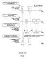
- FIG. 2illustrates radio signals on the time series transmitted and received between communication terminal apparatus 12 and base station apparatus 11 when communication terminal apparatus 12 starts radio communication.
- base station apparatus 11transmits a pilot signal with certain power to a plurality of communication terminal apparatuses 12 using a common pilot channel (CPICH) on downlink.
- CPICHcommon pilot channel
- communication terminal apparatus 12when receiving the pilot signal, transmits an access request signal with transmission power associated with the reception quality (reception power of the pilot signal on the CPICH in FIG. 2 ) to base station apparatus 11 using a random access channel (RACH) on uplink.
- RACHrandom access channel
- Resources used as a sub-channel of the RACHare predetermined such as, for example, timing, channelization code, subcarrier and the like, and communication terminal apparatus 12 randomly selects one from the predetermined resources in transmitting the access request signal.
- base station apparatus 11transmits an access permission signal with certain power to communication terminal apparatus 12 using a forward access channel (FACH). Then, when receiving the access permission signal, communication terminal apparatus 12 transmits a data packet with transmission power associated with the reception quality of the pilot signal to base station apparatus 11 using a data channel on uplink.
- FACHforward access channel
- communication terminal apparatus 12transmits a data packet with transmission power associated with the reception quality of the pilot signal to base station apparatus 11 using a data channel on uplink.
- the down arrowrepresents downlink
- the up arrowrepresents uplink, in each channel.
- communication terminal apparatus 12first transmits a short packet called preamble to base station apparatus 11 while increasing the transmission power gradually, and when base station apparatus 11 detects the preamble, communication terminal apparatus 12 transmits an access request signal to base station apparatus 11 (for example, see Patent Document 1).
- a plurality of communication terminal apparatuses 12concurrently receives the pilot signal on the CPICH, and randomly selects sub-channels of the RACH to transmit access request signals, so that there is a risk that a plurality of communication terminal apparatuses 12 transmits access request signals on the same sub-channel, and base station apparatus 11 cannot receive the access request signals.
- base station apparatus 11When base station apparatus 11 cannot receive an access request signal from communication terminal apparatus 12 , base station apparatus 11 does not transmit an access permission signal to communication terminal apparatus 12 . Therefore, communication terminal apparatus 12 determines that the previously transmitted access request signal is not received at base station apparatus 11 after a predetermined time has elapsed since transmission of the access request signal, and transmits the access request signal again to base station apparatus 11 after a lapse of predetermined back-off time.
- communication terminal apparatus 12 - 2 positioned near the cell edgetransmits the access request signal with high power over a plurality of times, so that a problem arises that the access request signal becomes an interfering signal in adjacent other cells.
- base station apparatus 11when receiving an access request signal, base station apparatus 11 cannot confirm the position of communication terminal apparatus 12 transmitting the access request signal, and base station apparatus 11 transmits an access permission signal with a large amount of power to be transmitted using the FACH without performing transmission power control so that all communication terminal apparatuses 12 located in the cell can receive the access permission signal, and a problem thereby arises that the access permission signal becomes an interfering signal in adjacent other cells in the same way as described above.
- communication terminal apparatus 12transmits the access request signal with required sufficient power obtained by using the preamble to base station apparatus 11 , so that the problem is thus improved that the access request signal transmitted from communication terminal apparatus 12 - 2 located near the cell edge becomes an interfering signal in adjacent other cells.
- any improvementsare not obtained in the problem that the throughput deteriorates due to the occurrence of collision of the access request signals, and in the problem that the access permission signal transmitted from base station apparatus 11 becomes an interfering signal in adjacent other cells.
- a communication terminal apparatusis a communication terminal apparatus which performs radio communication with a base station apparatus, and adopts a configuration provided with a receiving section that receives a pilot signal transmitted from the base station apparatus, a measuring section that measures reception quality of the received pilot signal, a selecting section that selects a sub-channel to be used in transmitting a signal to the base station apparatus according to a measurement result of the reception quality of the pilot signal, and a transmitting section that transmits the signal to the base station apparatus using the selected sub-channel.
- the inventioneven when access request signals are transmitted concurrently from a plurality of communication terminal apparatuses in a cell of the apparatuses, it is possible to avoid collision of the signals, prevent the occurrence of an interfering signal in other cells adjacent to the cell, improve throughput in the cell, and further prevent the occurrence of an interfering signal in other cells adjacent to the cell by controlling transmission power of an access permission signal.
- FIG. 1is a diagram schematically illustrating a configuration of a radio communication system according to conventional technique
- FIG. 2is a diagram illustrating radio signals on the time series transmitted and received between a communication terminal apparatus and base station apparatus when the communication terminal apparatus starts communication according to the conventional technique
- FIG. 3is a diagram schematically illustrating a configuration of a radio communication system according to Embodiment 1 of the present invention
- FIG. 4is a block diagram illustrating a configuration of a communication terminal apparatus according to Embodiment 1 of the present invention.
- FIG. 5is a block diagram illustrating a configuration of a base station apparatus according to Embodiment 1 of the present invention.
- FIG. 6is a diagram illustrating an example of an assignment mode of sub-channels of RACH to each group divided by reception quality of a pilot signal when channelization codes are used as the sub-channels of the RACH in Embodiment 1 of the present invention
- FIG. 7is a diagram illustrating another example of the assignment mode of sub-channels of RACH to each group divided by reception quality of the pilot signal when subcarriers in a multicarrier signal are used as the sub-channels of the RACH in Embodiment 1 of the present invention
- FIG. 8is a diagram illustrating still another example of the assignment mode of sub-channels of RACH to each group divided by reception quality of the pilot signal when symbols of an OFDM signal are used as the sub-channels of the RACH in Embodiment 1 of the present invention
- FIG. 9is a diagram illustrating a correspondence between each group of divided communication terminal apparatuses and reception quality of the pilot signal in Embodiment 1 of the present invention.
- FIG. 10is a diagram illustrating a correspondence between each group of divided communication terminal apparatuses and transmission power of an access permission signal in Embodiment 1 of the present invention.
- FIG. 11is a diagram illustrating radio signals on the time series transmitted and received between the communication terminal apparatus and base station apparatus when the communication terminal apparatus starts communication in Embodiment 1 of the present invention
- FIG. 12is another diagram illustrating radio signals on the time series transmitted and received between the communication terminal apparatus and base station apparatus when the communication terminal apparatus starts communication in Embodiment 1 of the present invention
- FIG. 13is still another diagram illustrating radio signals on the time series transmitted and received between the communication terminal apparatus and base station apparatus when the communication terminal apparatus starts communication in Embodiment 1 of the present invention
- FIG. 14is a block diagram illustrating a configuration of a base station apparatus according to Embodiment 2 of the present invention.
- FIG. 15is a diagram illustrating a correspondence between each group of divided communication terminal apparatuses and a set of a modulation scheme and coding rate in Embodiment 2 of the invention.
- FIG. 3schematically illustrates a configuration of a radio communication system according to Embodiment 1 of the present invention.
- the radio communication system according to this embodimentis comprised of a plurality of communication terminal apparatuses 200 and base station apparatus 300 .
- the plurality of communication terminal apparatuses 200is classified into three groups based on reception quality of a pilot signal transmitted from base station apparatus 300 on CPICH, for example.
- the groupsare referred to as group 1 , group 2 and group 3 , in descending order of the reception quality.
- communication terminal apparatuses belonging to group 1are described as communication terminal apparatuses 200 - 1
- communication terminal apparatuses belonging to group 2are described as communication terminal apparatuses 200 - 2
- communication terminal apparatuses belonging to group 3are described as communication terminal apparatuses 200 - 3 . Accordingly, communication terminal apparatuses 200 existing near a cell edge belong to group 3 in the radio communication system.
- FIG. 4is a block diagram illustrating a configuration of communication terminal apparatus 200 according to Embodiment 1 of the invention.
- Communication terminal apparatus 200has reception radio section 201 , channel dividing section 202 , demodulation section 203 , decoding section 204 , reception quality measuring section 205 , used sub-channel selecting section 206 , coding section 207 , modulation section 208 , sub-channel assigning section 209 , transmission power control section 211 , transmission radio section 212 and antenna element 213 .
- Reception radio section 201receives a pilot signal transmitted on CPICH via antenna element 213 , access permission signal transmitted on FACH and the like from base station apparatus 300 described later, performs predetermined reception processing such as frequency conversion, analog/digital conversion and the like on the received signals, and inputs the received signals subjected to the reception processing to channel dividing section 202 .
- Channel dividing section 202determines a channel used in the received signals input from reception radio section 201 , and when the determined channel is the CPICH, inputs the received signal, namely pilot signal to reception quality measuring section 205 . Meanwhile, when the determined channel is other than the CPICH namely FACH and the like, channel dividing section 202 inputs the received signal to demodulation section 203 .
- Demodulation section 203demodulates the received signal input from channel dividing section 202 with a predetermined scheme, and inputs the demodulated received signal to decoding section 204 .
- Decoding section 204decodes the received signal input from demodulation section 203 with a predetermined scheme to generate reception data, and inputs the generated reception data to a control section and the like not shown.
- Reception quality measuring section 205measures reception quality of the pilot signal input from channel dividing section 202 , for example, Signal-to-Interference power Ratio (SIR), or a reception power level, and reports the measurement result to used sub-channel selecting section 206 and transmission power control section 211 .
- SIRSignal-to-Interference power Ratio
- Used sub-channel selecting section 206has a “correspondence table” between classified reception quality of the pilot signal and sub-channel assigned to each class. Then, based on the correspondence table, used sub-channel selecting section 206 selects a sub-channel group of the RACH associated with the measurement result of the reception quality of the pilot signal reported from reception quality measuring section 205 , and randomly selects a single sub-channel for use in transmission of an access request signal from among the selected sub-channel group. Used sub-channel selecting section 206 reports the selected sub-channel to sub-channel assigning section 209 . In addition, the correspondence table will be described later where the classified reception quality of the pilot signal and sub-channel of the RACH assigned to each class are indicated.
- Coding section 207codes transmission data input from the control section and the like not shown with a predetermined scheme to generate a transmission signal, and inputs the generated transmission signal to modulation section 208 .
- sub-channel assigning section 209assigns a predetermined resource to an access request signal input from the control section and the like not shown so as to transmit the access request signal on the sub-channel of the RACH reported from used sub-channel selecting section 206 .
- the predetermined resourceinclude timing, channelization codes, subcarriers in a multicarrier signal and the like. Then, sub-channel assigning section 209 inputs the access request signal assigned the predetermined resource to transmission power control section 211 at predetermined timing.
- sub-channel assigning section 209assigns again the sub-channel of the RACH reported from used sub-channel selecting section 206 to the access request signal after a lapse of predetermined back-off time, and inputs the assigned access request signal to transmission power control section 211 .
- sub-channel assigning section 209assigns a predetermined resource to the transmission signal input from modulation section 208 so as to transmit the transmission signal on a data channel designated by the access permission signal, and inputs the transmission signal to transmission power control section 211 at predetermined timing.
- Transmission power control section 211amplifies the access request signal or transmission signal input from sub-channel assigning section 209 to provide power associated with the measurement result of the reception quality of the pilot signal reported from reception quality measuring section 205 , and inputs the amplified access request signal or transmission signal to transmission radio section 212 .
- Transmission radio section 212performs predetermined transmission processing such as digital/analog conversion, frequency conversion and the like on the access request signal or transmission signal input from transmission power control section 211 , and wirelessly transmits the signal to base station apparatus 300 via antenna element 213 .
- FIG. 5is a block diagram illustrating a configuration of base station apparatus 300 according to Embodiment 1 of the invention.
- Base station apparatus 300has reception radio section 301 , RACH detecting section 302 , demodulation section 303 , decoding section 304 , required transmission power calculating section 305 , coding section 306 , modulation section 307 , transmission power control section 308 , multiplexing section 309 , transmission radio section 311 and antenna element 312 .
- Reception radio section 301receives the access request signal transmitted on the RACH and transmission signal transmitted on the data channel from communication terminal apparatus 200 via antenna element 312 , performs predetermined reception processing such as frequency conversion, analog/digital conversion and the like on the received signals, and inputs the received signals subjected to the reception processing to RACH detecting section 302 .
- RACH detecting section 302detects the access request signal from the received signals input from reception radio section 301 , and when the access request signal is detected, inputs the access request signal to required transmission power calculating section 305 . Meanwhile, when the access request signal is not detected, RACH detecting section 302 determines that the received signals include only normal data signals, and inputs the received signals to demodulation section 303 .
- Demodulation section 303performs demodulation processing on the received signal input from RACH detecting section 302 with a predetermined scheme, and inputs the demodulated received signal to decoding section 304 .
- Decoding section 304decodes the received signal input from demodulation section 303 with a predetermined scheme to generate reception data, and inputs the generated reception data to a control section and the like not shown.
- Required transmission power calculating section 305determines the sub-channel of the RACH used in transmission of the access request signal input from RACH detecting section 302 .
- Required transmission power calculating section 305has the correspondence table that used sub-channel selecting section 206 has, and based on the correspondence table, required transmission power calculating section 305 recognizes the reception quality of the pilot signal in communication terminal apparatus 200 from the determined RACH sub-channel. Further, required transmission power calculating section 305 also has a “conversion table” that associates the determined sub-channel with transmission power of the access permission signal, calculates the transmission power associated with the determined RACH sub-channel using the conversion table, and reports the calculated transmission power to transmission power control section 308 . In addition, the conversion table will be described later.
- Coding section 306performs coding processing on the access permission signal or transmission data input from the control section and the like not shown with a predetermined scheme to generate a transmission signal, and inputs the generated transmission signal to modulation section 307 .
- Modulation section 307modulates the transmission signal input from coding section 306 with a predetermined scheme, and inputs the modulated transmission signal to transmission power control section 308 .
- Transmission power control section 308amplifies the transmission signal input from modulation section 307 to provide power reported from required transmission power calculating section 305 , and inputs the amplified transmission signal to multiplexing section 309 .
- Multiplexing section 309receives a pilot signal from the control section and the like not shown periodically, multiplexes the pilot signal on the transmission signal input from transmission power control section 308 at timing at which the pilot signal is input, and inputs the multiplexed transmission signal to transmission radio section 311 .
- multiplexing section 309causes the transmission signal input from transmission power control section 308 to pass through transmission radio section 311 without change at timing at which the pilot signal is not input.
- Transmission radio section 311performs transmission processing such as digital/analog conversion, frequency conversion and the like on the transmission signal input from multiplexing section 309 , and wirelessly transmits the transmission signal subjected to the transmission processing to communication terminal apparatus 200 via antenna element 312 .
- communication terminal apparatus 200 and base station apparatus 300will be described below in detail with reference to FIG. 6 to FIG. 13 .
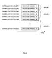
- FIG. 6shows an assignment mode of channelization codes to group 1 , group 2 and group 3 classified based on the reception quality of the pilot signal when communication terminal apparatus 200 uses the channelization code as a resource of the sub-channel of the RACH.
- two channelization codes # 1 and # 2are assigned to group 1 with the highest reception quality of the pilot signal
- three channelization codes # 3 , # 4 and # 5are assigned to group 2 with the middle reception quality
- all of remaining usable channelization codes # 6 to #n(n is a natural number of ten or more), are assigned to group 3 with the lowest reception quality.
- FIG. 7shows an assignment mode of subcarriers to group 1 , group 2 and group 3 classified based on the reception quality of the pilot signal when communication terminal apparatus 200 uses the subcarriers in a multicarrier signal as a resource of the sub-channel of the RACH.
- two subcarriers # 1 and # 2are assigned to group 1 with the highest reception quality of the pilot signal
- three subcarriers # 3 , # 4 and # 5are assigned to group 2 with the middle reception quality
- all of remaining usable subcarriers # 6 to #n(n is a natural number of ten or more) are assigned to group 3 with the lowest reception quality.
- FIG. 8shows an assignment mode of symbols of an OFDM (Orthogonal Frequency Division Multiplexing) signal to group 1 , group 2 and group 3 classified based on the reception quality of the pilot signal when communication terminal apparatus 200 uses the symbols in an OFDM signal as a resource of the sub-channel of the RACH.
- first two symbols of an OFDM signalare assigned to group 1 with the highest reception quality of the pilot signal
- subsequent three symbols of the OFDM signalare assigned to group 2 with the middle reception quality
- all of remaining usable symbols of the OFDM signalare assigned to group 3 with the lowest reception quality.
- the resource of the sub-channel of the RACHis a time slot standardized in a communication scheme
- the time slotcan be assigned as in the symbol of an OFDM signal.
- FIG. 9shows an example of the correspondence table provided in used sub-channel selecting section 206 .
- group 1is of the case that the measurement result of reception SIR is 15 dB or more as the reception quality of the pilot signal by reception quality measuring section 205
- group 2is of the case that the measurement result is 5 to 15 dB
- group 3is of the case that the measurement result is ⁇ 3 to 5 dB.
- Group 1 , group 2 and group 3 as shown in FIG. 9are respectively assigned sub-channels in modes as shown in FIG. 6 to FIG. 8 . Accordingly, based on the correspondence table, used sub-channel selecting section 206 selects sub-channels of the RACH assigned in the modes as shown in FIGS.
- any groupsare not associated with the case that the measurement result is less than ⁇ 3 dB in the reception quality of the pilot signal by reception quality measuring section 205 . This is because when the measurement result of the reception quality of the pilot signal is less than ⁇ 3 dB, the propagation path condition is excessively poor, and the risk is thereby high that base station apparatus 300 does not receive an access request signal even when communication terminal apparatus 200 transmits the access request signal.
- communication terminal apparatus 200in order to prevent the occurrence of an interfering signal in adjacent other cells, communication terminal apparatus 200 is prevented from transmitting an unnecessary access request signal.
- communication terminal apparatus 200when communication terminal apparatus 200 recovers from the attenuation due to fading, shadowing or the like on the propagation path and has the measurement result of ⁇ 3 dB or more in the reception quality of the pilot signal, communication terminal apparatus 200 can access base station apparatus 300 .
- FIG. 10shows an example of the conversion table that required transmission power calculating section 305 has.
- the conversion tablehas a correlation with the correspondence table as shown in FIG. 9 .
- the transmission power of the access permission signal in base station apparatus 300is expressed by decibel based on the transmission power of the pilot signal.
- the transmission power of the access permission signal in base station apparatus 300is set at ⁇ 15 dB based on the transmission power of the pilot signal.
- the transmission power of the access permission signal in base station apparatus 300is set at ⁇ 5 dB based on the transmission power of the pilot signal.
- the transmission power of the access permission signal in base station apparatus 300is set at 3 dB based on the transmission power of the pilot signal.
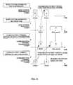
- FIG. 11illustrates radio signals on the time series transmitted and received between communication terminal apparatus 200 - 1 belonging to group 1 and base station apparatus 300 when communication terminal apparatus 200 - 1 starts communication.
- FIG. 12illustrates radio signals on the time series transmitted and received between communication terminal apparatus 200 - 2 belonging to group 2 and base station apparatus 300 when communication terminal apparatus 200 - 2 starts communication.
- FIG. 13illustrates radio signals on the time series transmitted and received between communication terminal apparatus 200 - 3 belonging to group 3 and base station apparatus 300 when communication terminal apparatus 200 - 3 starts communication.
- a reception power level of a pilot signalis used as the reception quality of the pilot signal. As shown in FIG. 11 to FIG.
- communication terminal apparatuses 200 - 1 to 200 - 3perform transmission power control on the access request signal transmitted on the RACH and a data packet transmitted on the data channel.
- base station apparatus 300determines the sub-channel of the RACH used by communication terminal apparatus 200 , indirectly recognizes the measurement result of the reception quality of the pilot signal in communication terminal apparatus 200 , namely recognizes that communication terminal apparatus 200 belongs to which group among groups 1 to 3 , and performs transmission power control on the access permission signal transmitted on the FACH. Accordingly, by comparing between FIG. 11 and FIG. 13 , it is understood that the transmission power on the FACH to transmit the access permission signal is different from one another, and that the transmission power on the FACH is the highest in FIG. 13 showing communication terminal apparatus 200 - 3 with the lowest reception quality of the pilot signal.
- communication terminal apparatus 200classifies measurement results of the reception quality of the pilot signal, assigns dedicated RACH sub-channels to each class beforehand, and selects an RACH sub-channel to use in transmitting an access request signal according to an actual measurement result, so that it is possible to decrease the probability that a plurality of communication terminal apparatuses 200 concurrently uses the same RACH sub-channel.
- the access request signalis received reliably in base station apparatus 300 , the number of retransmissions of the access request signal decreases, so that it is possible for communication terminal apparatus 200 to start radio communication in a short period, improve throughput in the cell, and prevent the occurrence of an interfering signal in other cells adjacent to the cell.
- base station apparatus 300transmits the access permission signal with required sufficient transmission power according to the reception quality of the access request signal in each of communication terminal apparatuses 200 - 1 to 200 - 3 , so that it is possible to prevent the access permission signal from being an interfering signal in other cells adjacent to the cell of base station apparatus 300 .
- a larger number of sub-channelsare assigned to a lower class (for example, group 3 ) than a higher class (for example, group 1 ) in classified reception quality of the pilot signal.
- communication terminal apparatuses 200 positioned nearer the cell edgedecrease the probability of concurrently using the same RACH sub-channel, and the number of retransmissions of the access request signal decreases that it is possible to efficiently prevent the occurrence of the interfering signal in other cells adjacent to the cell of communication terminal apparatuses 200 .
- a range of the reception quality in a lower classis narrower than that in a higher class. More specifically, the range of the reception quality of group 1 is 15 dB or more without an upper limit, the range of the reception quality of group 2 is 10 dB of between 5 and 15 dB, and the range of the reception quality of group 3 is 8 dB of between ⁇ 3 and 5 dB.
- the radio communication systemsince a larger number of sub-channels are assigned to a lower class with a narrower range of the reception quality of the pilot signal, it is possible to further reduce efficiently the number of retransmissions of the access request signal of communication terminal apparatus 200 positioned near the cell edge, so that it is possible to prevent the occurrence of the interfering signal in other cells adjacent to the cell of communication terminal apparatus 200 more effectively.
- required transmission power calculating section 305determines a sub-channel of the RACH used in transmission of the access request signal, and reports transmission power control section 308 of transmission power associated with the determined sub-channel, but the invention is not limited to this case.
- required transmission power calculating section 305may have a request signal measuring section that measures reception quality of an access request signal, compare the reception quality measured in the request signal measuring section with required reception quality in communication terminal apparatus 200 , namely target reception quality in transmission power control, increase or decrease the transmission power associated with the sub-channel of the RACH when a difference of the reception quality is larger than a predetermined value, and report the increased or decreased transmission power to transmission power control section 308 .
- Calculation of the transmission power of the access permission signal in required transmission power calculating section 305is calculation by closed-loop based on the reception quality of the access request signal Therefore, when the time is required at communication terminal apparatus 200 from the reception of a pilot signal until the transmission of an access request signal or when the variation is intense in propagation path conditions, there is a risk that actual propagation path conditions are not reflected in the calculated transmission power. Then, if required transmission power calculating section 305 performs calculation of the transmission power by open-loop for measuring the reception quality of the access request signal, in addition to calculation of the transmission power by closed-loop, it is possible to perform transmission power control of the access permission signal more accurately.
- Embodiment 2 of the inventiondescribes the case where a base station apparatus varies adaptively a coding rate and modulation scheme on the FACH based on used resources of the RACH.
- a configuration of a communication terminal apparatus according to this embodimentis the same as that in FIG. 4 , and described using FIG. 4 .
- FIG. 14is a block diagram illustrating a configuration of base station apparatus 400 according to Embodiment 2 of the invention.
- Base station apparatus 400has reception radio section 301 , RACH detecting section 302 , demodulation section 303 , decoding section 304 , adaptive control section 413 , coding section 406 , modulation section 407 , multiplexing section 309 , transmission radio section 311 and antenna element 312 .
- Adaptive control section 413determines a sub-channel of the RACH used in transmission of an access request signal input from RACH detecting section 302 , sets a modulation scheme and coding rate using a conversion table that associates the determined sub-channel with a transmission parameter, namely a set of the modulation scheme and coding rate of an access permission signal, and inputs the set modulation scheme and coding rate to coding section 406 and modulation section 407 .
- Coding section 406performs coding processing on the access permission signal or transmission data input from the control section and the like not shown with the coding rate or coding method according to the transmission parameter (information of the coding rate and modulation scheme) input from adaptive control section 413 to generate a transmission signal, and inputs the generated transmission signal to modulation section 407 .
- Modulation section 407modulates the transmission signal input from coding section 406 with the modulation scheme according to the transmission parameter input from adaptive control section 413 , and inputs the modulated transmission signal to multiplexing section 309 .
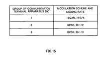
- FIG. 15shows an example of the conversion table that adaptive control section 413 has.
- the conversion tablehas a correlation with the correspondence table as shown in FIG. 9 , and as the reception quality in communication terminal apparatus 200 is higher, the modulation level and coding rate increase.
- group 3shows an example of the conversion table that adaptive control section 413 has.
- the conversion tablehas a correlation with the correspondence table as shown in FIG. 9 , and as the reception quality in communication terminal apparatus 200 is higher, the modulation level and coding rate increase.
- the transmission parameterhas higher transmission efficiency, it is possible for base station apparatus 400 to finish transmission of the access permission signal in a shorter time.
- base station apparatus 400transmits an access permission signal using a transmission parameter with the highest transmission efficiency that allows reception with a sufficiently low error rate according to the reception quality of the access request signal in each of communication terminal apparatuses 200 - 1 to 200 - 3 , so that it is possible to reduce the transmission time of the access permission signal, and prevent the access permission signal from being an interfering signal in other cells.
- Each function block employed in the description of each of the aforementioned embodimentsmay typically be implemented as an LSI constituted by an integrated circuit. These may be individual chips or partially or totally contained on a single chip. “LSI” is assumed here but this may also be referred to as “IC”, “system LSI”, “super LSI”, “ultra LSI” depending on differing extents of integration.
- circuit integrationis not limited to LSI's, and implementation using dedicated circuitry or general purpose processors is also possible.
- FPGAField Programmable Gate Array
- reconfigurable processorwhere connections and setting of circuit cells within an LSI can be reconfigured is also possible.
- the casehas been described where a plurality of communication terminal apparatuses 200 is divided into three groups in association with classes of the reception quality of the pilot signal, but the invention is not limited to this case.
- the number of groupsmay be increased.
- the access permission signalmay be transmitted, for example, in 3GPP standards, using AICH (Acknowledge Indicator Channel), FACH (Forward Access Channel), S-CCPCH (Secondary-Common Control Physical Channel), HS-SCCH (High Speed-Shared Control Channel), and DPCH (Dedicated Physical Channel).
- AICHAcknowledge Indicator Channel
- FACHForward Access Channel
- S-CCPCHSecondary-Common Control Physical Channel
- HS-SCCHHigh Speed-Shared Control Channel
- DPCHDedicated Physical Channel
- an access requestis made on the RACH
- access permissionis made on the FACH
- data packetsare transmitted.
- the same effectsare obtained when the RACH is used in transmission of data as well as the access request signal, and the FACH is used in transmission of data as well as the access permission signal.
- the data packet on uplinkmay be transmitted on the RACH
- the data packet on downlinkmay be transmitted on the FACH.
- the RACH in each of the above-mentioned embodimentsmay be another comparable channel to which resource are not assigned beforehand for each user.
- the reception qualityis estimated from the reception SIR, but the reception quality may be estimated from reception SNR, reception CIR, reception SINR, reception CINR, reception power, interfering power, bit error rate, throughput, MCS (a combination of a modulation scheme and coding rate) capable of achieving a predetermined error rate, and the like.
- the base station apparatusmay be represented by Node B, and the communication terminal apparatus may be represented by UE.
- a first aspect of the inventionis a communication terminal apparatus which performs radio communication with a base station apparatus, and has a receiving section that receives a pilot signal transmitted from the base station apparatus, a measuring section that measures reception quality of the received pilot signal, a selecting section that selects a sub-channel to be used in transmitting a signal to the base station apparatus according to a measurement result of the reception quality of the pilot signal, and a transmitting section that transmits the signal to the base station apparatus using the selected sub-channel.
- a second aspect of the inventionis a communication terminal apparatus where in the above-mentioned invention, the transmitting section transmits the signal using a random access channel.
- a third aspect of the inventionis a communication terminal apparatus where in the above-mentioned invention, the transmitting section transmits an access request signal.
- a fourth aspect of the inventionis a communication terminal apparatus where the selecting section assigns a larger number of sub-channels to a lower class than a higher class in classified reception quality, and selects the sub-channel to be used in transmitting the signal to the base station apparatus from among sub-channels assigned to a class corresponding to the measurement result of the reception quality of the pilot signal.
- a fifth aspect of the inventionis a communication terminal apparatus where in the above-mentioned invention, the selecting section assigns sub-channels to each class by narrowing a range of the reception quality for a lower class than a higher class in the classified reception quality, and selects the sub-channel to be used in transmitting the signal to the base station apparatus from among the sub-channels assigned to the class corresponding to the measurement result of the reception quality of the pilot signal.
- a sixth aspect of the inventionis a base station apparatus which performs radio communication with a communication terminal apparatus, and has a receiving section that receives a signal transmitted from the communication terminal apparatus, a detecting section that detects a sub-channel used in transmitting the received signal, and a transmitting section that transmits the signal to the communication terminal apparatus with transmission power associated with the detected sub-channel, or a modulation scheme and coding rate associated with the detected sub-channel.
- a seventh aspect of the inventionis the base station apparatus where in the above-mentioned invention, the transmitting section transmits an access permission signal.
- An eighth aspect of the inventionis a base station apparatus where in the above-mentioned embodiment, a request signal measuring section is further provided that measures reception quality of the signal received by the receiving section, and the transmitting section increases or decreases transmission power associated with the sub-channel detected in the detecting section, according to a difference between the reception quality measured by the request signal measuring section and target reception quality in transmission power control, and transmits the signal with increased or decreased power to the communication terminal apparatus.
- a ninth aspect of the inventionis a base station apparatus where in the above-mentioned invention, the receiving section receives the signal transmitted using a random access channel.
- a tenth aspect of the inventionis a radio communication system comprised of a communication terminal apparatus and a base station apparatus, where the communication terminal apparatus has a terminal receiving section that receives a pilot signal transmitted from the base station apparatus, a measuring section that measures reception quality of the received pilot signal, a selecting section that selects a sub-channel to be used in transmitting a signal to the base station apparatus according to a measurement result of the reception quality of the pilot signal, and a terminal transmitting section that transmits the signal to the base station apparatus using the selected sub-channel, and the base station apparatus has a base station receiving section that receives the signal transmitted from the communication terminal apparatus, a detecting section that detects the sub-channel used in transmitting the received signal, and a base station transmitting section that transmits the signal to the communication terminal apparatus with transmission power associated with the detected sub-channel.
- An eleventh aspect of the inventionis a radio communication system where in the above-mentioned invention, the terminal transmitting section transmits an access request signal.
- a twelfth aspect of the inventionis a radio communication system where in the above-mentioned invention, the base station transmitting section transmits an access permission signal.
- the communication terminal apparatus and base station apparatushave effects of decreasing the incidence of collision of access request signals in a cell of the apparatus, preventing the occurrence of an interfering signal in other cells adjacent to the cell, and improving throughput in the cell, and are useful in a radio communication system and the like.
Landscapes
- Engineering & Computer Science (AREA)
- Computer Networks & Wireless Communication (AREA)
- Signal Processing (AREA)
- Quality & Reliability (AREA)
- Mobile Radio Communication Systems (AREA)
- Detection And Prevention Of Errors In Transmission (AREA)
Abstract
Description
- Patent Document 1: Japanese Patent Application Laid-Open No. 2002-528997
Claims (18)
Applications Claiming Priority (3)
| Application Number | Priority Date | Filing Date | Title |
|---|---|---|---|
| JP2004173017 | 2004-06-10 | ||
| JP2004-173017 | 2004-06-10 | ||
| PCT/JP2005/010373WO2005122616A1 (en) | 2004-06-10 | 2005-06-06 | Communication terminal device, base station device, and radio communication system |
Related Parent Applications (1)
| Application Number | Title | Priority Date | Filing Date |
|---|---|---|---|
| PCT/JP2005/010373A-371-Of-InternationalWO2005122616A1 (en) | 2004-06-10 | 2005-06-06 | Communication terminal device, base station device, and radio communication system |
Related Child Applications (1)
| Application Number | Title | Priority Date | Filing Date |
|---|---|---|---|
| US14/066,316ContinuationUS9215733B2 (en) | 2004-06-10 | 2013-10-29 | Communication terminal device, base station device and radio communication method |
Publications (2)
| Publication Number | Publication Date |
|---|---|
| US20080070610A1 US20080070610A1 (en) | 2008-03-20 |
| US8571567B2true US8571567B2 (en) | 2013-10-29 |
Family
ID=35503532
Family Applications (2)
| Application Number | Title | Priority Date | Filing Date |
|---|---|---|---|
| US11/628,505Active2026-03-07US8571567B2 (en) | 2004-06-10 | 2005-06-06 | Communication terminal device, base station device and radio communication system in which a random access channel is accessed by employing an initial access code randomly selected from a selected group of initial access codes |
| US14/066,316Expired - LifetimeUS9215733B2 (en) | 2004-06-10 | 2013-10-29 | Communication terminal device, base station device and radio communication method |
Family Applications After (1)
| Application Number | Title | Priority Date | Filing Date |
|---|---|---|---|
| US14/066,316Expired - LifetimeUS9215733B2 (en) | 2004-06-10 | 2013-10-29 | Communication terminal device, base station device and radio communication method |
Country Status (9)
| Country | Link |
|---|---|
| US (2) | US8571567B2 (en) |
| EP (2) | EP1744577B1 (en) |
| JP (3) | JP5036305B2 (en) |
| KR (2) | KR101123536B1 (en) |
| CN (2) | CN102711233B (en) |
| BR (1) | BRPI0512001B1 (en) |
| MX (1) | MXPA06014150A (en) |
| RU (2) | RU2382524C2 (en) |
| WO (1) | WO2005122616A1 (en) |
Cited By (4)
| Publication number | Priority date | Publication date | Assignee | Title |
|---|---|---|---|---|
| US20120033646A1 (en)* | 2010-02-19 | 2012-02-09 | Qualcomm Incorporated | System access for heterogeneous networks |
| US10070397B2 (en) | 2006-10-03 | 2018-09-04 | Interdigital Technology Corporation | Combined open loop/closed loop (CQI-based) uplink transmit power control with interference mitigation for E-UTRA |
| US10091740B2 (en) | 2007-03-07 | 2018-10-02 | Interdigital Technology Corporation | Combined open loop/closed loop method for controlling uplink power of a mobile station |
| US10763932B2 (en) | 2016-12-08 | 2020-09-01 | Nec Corporation | Base station apparatus, wireless communication system, method and non-transitory storage medium |
Families Citing this family (59)
| Publication number | Priority date | Publication date | Assignee | Title |
|---|---|---|---|---|
| WO2005122616A1 (en) | 2004-06-10 | 2005-12-22 | Matsushita Electric Industrial Co., Ltd. | Communication terminal device, base station device, and radio communication system |
| WO2006077647A1 (en)* | 2005-01-24 | 2006-07-27 | Fujitsu Limited | Transmission power control method and mobile terminal device |
| EP3461213A1 (en)* | 2005-11-04 | 2019-03-27 | LG Electronics Inc. | Random access dimensioning methods and procedures for frequency division multiplexing access systems |
| JPWO2007091420A1 (en)* | 2006-02-06 | 2009-07-02 | パナソニック株式会社 | Base station and communication system |
| US8139473B2 (en) | 2006-03-20 | 2012-03-20 | Panasonic Corporation | Radio communication mobile station apparatus and radio communication method |
| US8189621B2 (en) | 2006-05-12 | 2012-05-29 | Microsoft Corporation | Stack signaling to application with lack of requested bandwidth |
| WO2008016248A1 (en)* | 2006-07-31 | 2008-02-07 | Electronics And Telecommunications Research Institute | Random access method using different frequency hopping patterns between neighboring cells and mobile communication device |
| KR101320398B1 (en) | 2006-07-31 | 2013-10-22 | 삼성전자주식회사 | Random Access Method using different frequency hopping patterns between neighboring cells and mobile communication device |
| WO2008018039A2 (en)* | 2006-08-09 | 2008-02-14 | Koninklijke Philips Electronics N.V. | Radio communication station and radio communication device, and methods of operating same. |
| DE602007010318D1 (en) | 2006-08-22 | 2010-12-16 | Koninkl Philips Electronics Nv | METHOD FOR TRANSMITTING AND RECEIVING DATA AND DEVICE THEREFOR |
| KR101265643B1 (en) | 2006-08-22 | 2013-05-22 | 엘지전자 주식회사 | A mothod of executing handover and controlling thereof in mobile communication system |
| CN101513112B (en) | 2006-08-29 | 2012-12-12 | 夏普株式会社 | Mobile Communication System, Mobile Station Device, Base Station Device, and Random Access Channel Transmission Method |
| US8285150B2 (en)* | 2006-10-02 | 2012-10-09 | Futurewei Technologies, Inc. | Method and system for integrated DWDM transmitters |
| US8285149B2 (en)* | 2006-10-02 | 2012-10-09 | Futurewei Technologies, Inc. | Method and system for integrated DWDM transmitters |
| KR101430449B1 (en) | 2006-10-02 | 2014-08-14 | 엘지전자 주식회사 | Method for transmitting and receiving paging message in wireless communication system |
| US8050525B2 (en)* | 2006-10-11 | 2011-11-01 | Futurewei Technologies, Inc. | Method and system for grating taps for monitoring a DWDM transmitter array integrated on a PLC platform |
| US8285151B2 (en)* | 2006-10-20 | 2012-10-09 | Futurewei Technologies, Inc. | Method and system for hybrid integrated 1XN DWDM transmitter |
| KR101443618B1 (en)* | 2006-10-30 | 2014-09-23 | 엘지전자 주식회사 | A random access channel message response method, a random access channel message transmission method, and a mobile communication terminal |
| EP2057862B1 (en) | 2006-10-30 | 2017-02-01 | LG Electronics Inc. | Method for re-direction of uplink access |
| KR100965673B1 (en) | 2006-11-15 | 2010-06-24 | 삼성전자주식회사 | Data transmission method in mobile communication system |
| WO2008060201A1 (en)* | 2006-11-17 | 2008-05-22 | Telefonaktiebolaget L M Ericsson (Publ) | A mobile station communicating with a base station via a separate uplink when the parameters of channel quality fall below the predefined threholds |
| US8144793B2 (en) | 2006-12-12 | 2012-03-27 | Microsoft Corporation | Cognitive multi-user OFDMA |
| US8825065B2 (en)* | 2007-01-19 | 2014-09-02 | Wi-Lan, Inc. | Transmit power dependent reduced emissions from a wireless transceiver |
| US20080268833A1 (en)* | 2007-03-30 | 2008-10-30 | Leping Huang | System and Method for Self-Optimization of Interference Coordination in Communication Systems |
| US8081662B2 (en) | 2007-04-30 | 2011-12-20 | Lg Electronics Inc. | Methods of transmitting data blocks in wireless communication system |
| KR100917205B1 (en) | 2007-05-02 | 2009-09-15 | 엘지전자 주식회사 | Method of configuring a data block in wireless communication system |
| US7970085B2 (en) | 2007-05-08 | 2011-06-28 | Microsoft Corporation | OFDM transmission and reception for non-OFDMA signals |
| US8064922B2 (en) | 2007-06-08 | 2011-11-22 | Sharp Kabushiki Kaisha | Scheduling of reception quality information transmission for mobile stations |
| CA2633152C (en)* | 2007-06-12 | 2016-08-16 | Sennet Communications | Tone based cognitive radio for opportunistic communications |
| KR101470638B1 (en) | 2007-06-18 | 2014-12-08 | 엘지전자 주식회사 | Radio resource enhancement method, status information reporting method, and receiving apparatus in a mobile communication system |
| US9497642B2 (en)* | 2007-06-29 | 2016-11-15 | Alcatel Lucent | Method of automatically configuring a home base station router |
| KR100884384B1 (en)* | 2007-07-03 | 2009-02-17 | 한국전자통신연구원 | Method of changing transmission method, request method of packet retransmission and method of packet retransmission |
| EP2141844B1 (en) | 2007-09-06 | 2013-01-23 | Sharp Kabushiki Kaisha | Communication apparatus and communication method |
| JPWO2009038018A1 (en)* | 2007-09-21 | 2011-01-06 | シャープ株式会社 | Wireless transmission device, wireless communication system, and wireless transmission method |
| US8050238B2 (en)* | 2007-12-31 | 2011-11-01 | Motorola Mobility, Inc. | Method and apparatus for improving network access through multi-stage signaling |
| US8374130B2 (en) | 2008-01-25 | 2013-02-12 | Microsoft Corporation | Orthogonal frequency division multiple access with carrier sense |
| CN101252386B (en)* | 2008-03-26 | 2013-06-05 | 中兴通讯股份有限公司 | Mapping method of physical accidental access channel |
| KR101657554B1 (en) | 2008-04-21 | 2016-09-19 | 애플 인크. | Method and system for providing an uplink structure and minimizing pilot signal overhead in a wireless communication network |
| WO2009140985A1 (en)* | 2008-05-23 | 2009-11-26 | Nokia Siemens Networks Oy | Random access in flexible spectrum usage systems |
| TWI398178B (en)* | 2008-09-25 | 2013-06-01 | Skyphy Networks Ltd | Multi-hop wireless systems having noise reduction and bandwidth expansion capabilities and the methods of the same |
| KR101611271B1 (en) | 2008-10-29 | 2016-04-26 | 엘지전자 주식회사 | An uplink random access method under a carrier aggregation environment |
| US8396086B1 (en)* | 2009-09-30 | 2013-03-12 | Google Inc. | Scalable association scheme for TV white-space MIMO wireless system |
| US8559455B1 (en) | 2009-09-30 | 2013-10-15 | Google Inc. | Dynamic scheduling scheme for TV white-space MIMO wireless system |
| US8699411B1 (en) | 2009-09-30 | 2014-04-15 | Google Inc. | Dynamic TDMA system for TV white space MIMO wireless |
| US8565138B1 (en) | 2009-09-30 | 2013-10-22 | Google Inc. | Random shuffling mechanism for MIMO wireless system |
| US8442001B2 (en) | 2009-10-21 | 2013-05-14 | Qualcomm Incorporated | Systems, methods and apparatus for facilitating handover control using resource reservation with frequency reuse |
| US20130170420A1 (en)* | 2010-10-07 | 2013-07-04 | Panasonic Corporation | Wireless communication device, wireless communication method and processing circuit |
| GB2484922B (en) | 2010-10-25 | 2014-10-08 | Sca Ipla Holdings Inc | Infrastructure equipment and method |
| JP5702133B2 (en)* | 2010-12-22 | 2015-04-15 | 京セラ株式会社 | Communication apparatus and communication method |
| US20140016494A1 (en)* | 2011-02-14 | 2014-01-16 | Nokia Siemens Networks Oy | Secondary Spectrum Use |
| WO2013042221A1 (en)* | 2011-09-21 | 2013-03-28 | 富士通株式会社 | Wireless communication system, wireless base station, wireless terminal, and communication control method |
| WO2013140519A1 (en) | 2012-03-19 | 2013-09-26 | 富士通株式会社 | Communication system, communication method, mobile communication terminal, and base station |
| US10080188B2 (en)* | 2014-02-27 | 2018-09-18 | Conversant Intellectual Property Management Inc. | System and method for controlling a wireless network |
| CN105636235B (en)* | 2014-11-07 | 2019-03-19 | 联想(北京)有限公司 | Information processing method and base station |
| US20160192219A1 (en)* | 2014-12-30 | 2016-06-30 | Electronics And Telecommunications Research Institute | Method for assigning radio resource and communication system supporting the same |
| JP2019057749A (en)* | 2016-02-04 | 2019-04-11 | シャープ株式会社 | TERMINAL DEVICE, BASE STATION DEVICE, COMMUNICATION METHOD, AND INTEGRATED CIRCUIT |
| US11121747B2 (en)* | 2016-07-13 | 2021-09-14 | Sony Corporation | Wireless communication device and wireless communication method |
| JP2019169749A (en)* | 2016-08-10 | 2019-10-03 | シャープ株式会社 | Transmitter and communication method |
| CN115002919B (en)* | 2022-07-15 | 2022-11-08 | 北京九天微星科技发展有限公司 | Channel resource allocation method and device in low-orbit satellite system |
Citations (24)
| Publication number | Priority date | Publication date | Assignee | Title |
|---|---|---|---|---|
| US5203008A (en)* | 1989-11-28 | 1993-04-13 | Nippon Telegraph & Telephone Corporation | Method of assigning radio communication channels to each of a plurality of mobile stations |
| JPH05292010A (en) | 1992-04-10 | 1993-11-05 | Fujitsu Ltd | Method and device for assigning radio channel |
| JPH07336757A (en) | 1994-06-09 | 1995-12-22 | Toshiba Corp | Mobile radio communication system |
| US5581547A (en) | 1993-03-05 | 1996-12-03 | Ntt Mobile Communications Network Inc. | Random access communication method by CDMA and mobile station equipment using the same |
| JP2688686B2 (en) | 1993-03-05 | 1997-12-10 | エヌ・ティ・ティ移動通信網株式会社 | CDMA random access communication method and mobile station apparatus using the same |
| JPH10117373A (en) | 1996-10-08 | 1998-05-06 | Y R P Ido Tsushin Kiban Gijutsu Kenkyusho:Kk | Channel assignment method and communication network using the method |
| US5758090A (en)* | 1995-09-22 | 1998-05-26 | Airnet Communications, Inc. | Frequency reuse planning for CDMA cellular communication system by grouping of available carrier frequencies and power control based on the distance from base station |
| US6052594A (en) | 1997-04-30 | 2000-04-18 | At&T Corp. | System and method for dynamically assigning channels for wireless packet communications |
| WO2000025443A1 (en)* | 1998-10-28 | 2000-05-04 | Koninklijke Philips Electronics N.V. | Radio communication system |
| US20010036113A1 (en)* | 2000-04-04 | 2001-11-01 | Jens-Uwe Jurgensen | Prioritisation method for users randomly accessing a common communication channel |
| US20010038619A1 (en)* | 2000-04-07 | 2001-11-08 | Philips Corporation | Radio communication system and method of operating the system |
| US20020123349A1 (en) | 2000-06-26 | 2002-09-05 | Kenichi Miyoshi | Base station apparatus and communication method |
| US20030036361A1 (en)* | 1999-12-24 | 2003-02-20 | Hiroyuki Kawai | Method and device for transmitting burst signal in mobile communication system, information distribution method, and information distribution controller |
| JP2003087192A (en) | 2001-09-13 | 2003-03-20 | Matsushita Electric Ind Co Ltd | Transmission power setting method and base station apparatus |
| US20030095528A1 (en)* | 1998-10-05 | 2003-05-22 | John Halton | Random access channel prioritization scheme |
| JP2003298510A (en) | 2000-06-26 | 2003-10-17 | Matsushita Electric Ind Co Ltd | Transmission power control method |
| CN1474525A (en) | 2002-08-09 | 2004-02-11 | 华为技术有限公司 | Signal Transmitting and Receiving Method Based on Time Division Duplex in Wireless Communication System |
| WO2004030392A1 (en) | 2002-09-27 | 2004-04-08 | Telefonaktiebolaget Lm Ericsson (Publ) | Requesting and controlling access in a wireless communications network |
| WO2004038951A2 (en) | 2002-10-25 | 2004-05-06 | Qualcomm, Incorporated | Random access for wireless multiple-access communication systems |
| US20040204101A1 (en) | 2003-04-11 | 2004-10-14 | Ntt Docomo, Inc. | Base station, mobile station, communication system, transmission control method, and mobile station control program |
| WO2005115034A1 (en) | 2004-05-21 | 2005-12-01 | Mitsubishi Denki Kabushiki Kaisha | Third-generation mobile communication/radio lan integration system, and third-generation mobile communication/radio lan integration method |
| US20070091815A1 (en) | 2005-10-21 | 2007-04-26 | Peerapol Tinnakornsrisuphap | Methods and systems for adaptive encoding of real-time information in packet-switched wireless communication systems |
| US20080070610A1 (en) | 2004-06-10 | 2008-03-20 | Matsushita Electric Industrial Co., Ltd. | Communication Terminal Device, Base Station Device and Radio Communication System |
| JP5292010B2 (en) | 2008-07-31 | 2013-09-18 | 株式会社日立ビルシステム | Condominium management system |
Family Cites Families (3)
| Publication number | Priority date | Publication date | Assignee | Title |
|---|---|---|---|---|
| US5265119A (en)* | 1989-11-07 | 1993-11-23 | Qualcomm Incorporated | Method and apparatus for controlling transmission power in a CDMA cellular mobile telephone system |
| WO1998058503A1 (en)* | 1997-06-16 | 1998-12-23 | Mitsubishi Denki Kabushiki Kaisha | Mobile communication system |
| JP3679089B2 (en) | 2002-11-20 | 2005-08-03 | 松下電器産業株式会社 | Base station apparatus and retransmission packet transmission power control method |
- 2005
- 2005-06-06WOPCT/JP2005/010373patent/WO2005122616A1/ennot_activeCeased
- 2005-06-06CNCN201210122020.7Apatent/CN102711233B/ennot_activeCeased
- 2005-06-06MXMXPA06014150Apatent/MXPA06014150A/enactiveIP Right Grant
- 2005-06-06EPEP05751589Apatent/EP1744577B1/ennot_activeExpired - Lifetime
- 2005-06-06JPJP2006514500Apatent/JP5036305B2/ennot_activeExpired - Lifetime
- 2005-06-06KRKR1020067025970Apatent/KR101123536B1/ennot_activeExpired - Lifetime
- 2005-06-06KRKR1020117031686Apatent/KR101406626B1/ennot_activeExpired - Lifetime
- 2005-06-06CNCN2005800190471Apatent/CN1965602B/ennot_activeCeased
- 2005-06-06RURU2006143658/09Apatent/RU2382524C2/enactive
- 2005-06-06EPEP11168426.2Apatent/EP2364054B1/ennot_activeExpired - Lifetime
- 2005-06-06USUS11/628,505patent/US8571567B2/enactiveActive
- 2005-06-06BRBRPI0512001-2Apatent/BRPI0512001B1/enactiveIP Right Grant
- 2009
- 2009-10-30RURU2009140270/07Apatent/RU2503142C2/enactive
- 2010
- 2010-08-20JPJP2010185034Apatent/JP5295185B2/ennot_activeExpired - Lifetime
- 2013
- 2013-04-22JPJP2013089183Apatent/JP5428119B2/ennot_activeExpired - Lifetime
- 2013-10-29USUS14/066,316patent/US9215733B2/ennot_activeExpired - Lifetime
Patent Citations (33)
| Publication number | Priority date | Publication date | Assignee | Title |
|---|---|---|---|---|
| US5203008A (en)* | 1989-11-28 | 1993-04-13 | Nippon Telegraph & Telephone Corporation | Method of assigning radio communication channels to each of a plurality of mobile stations |
| JPH05292010A (en) | 1992-04-10 | 1993-11-05 | Fujitsu Ltd | Method and device for assigning radio channel |
| US5448751A (en) | 1992-04-10 | 1995-09-05 | Fujitsu Limited | Method and apparatus for assigning radio channels in mobile communications systems |
| US5581547A (en) | 1993-03-05 | 1996-12-03 | Ntt Mobile Communications Network Inc. | Random access communication method by CDMA and mobile station equipment using the same |
| JP2688686B2 (en) | 1993-03-05 | 1997-12-10 | エヌ・ティ・ティ移動通信網株式会社 | CDMA random access communication method and mobile station apparatus using the same |
| JPH07336757A (en) | 1994-06-09 | 1995-12-22 | Toshiba Corp | Mobile radio communication system |
| US5758090A (en)* | 1995-09-22 | 1998-05-26 | Airnet Communications, Inc. | Frequency reuse planning for CDMA cellular communication system by grouping of available carrier frequencies and power control based on the distance from base station |
| JPH10117373A (en) | 1996-10-08 | 1998-05-06 | Y R P Ido Tsushin Kiban Gijutsu Kenkyusho:Kk | Channel assignment method and communication network using the method |
| US6052594A (en) | 1997-04-30 | 2000-04-18 | At&T Corp. | System and method for dynamically assigning channels for wireless packet communications |
| US20030095528A1 (en)* | 1998-10-05 | 2003-05-22 | John Halton | Random access channel prioritization scheme |
| WO2000025443A1 (en)* | 1998-10-28 | 2000-05-04 | Koninklijke Philips Electronics N.V. | Radio communication system |
| JP2002528997A (en) | 1998-10-28 | 2002-09-03 | コーニンクレッカ フィリップス エレクトロニクス エヌ ヴィ | Wireless communication system |
| US20040082357A1 (en) | 1998-10-28 | 2004-04-29 | Moulsley Timothy J. | Radio communication system |
| US20030036361A1 (en)* | 1999-12-24 | 2003-02-20 | Hiroyuki Kawai | Method and device for transmitting burst signal in mobile communication system, information distribution method, and information distribution controller |
| JP2001352573A (en) | 2000-04-04 | 2001-12-21 | Sony Internatl Europ Gmbh | Communication equipment and communication method |
| US20010036113A1 (en)* | 2000-04-04 | 2001-11-01 | Jens-Uwe Jurgensen | Prioritisation method for users randomly accessing a common communication channel |
| US20010038619A1 (en)* | 2000-04-07 | 2001-11-08 | Philips Corporation | Radio communication system and method of operating the system |
| US20020123349A1 (en) | 2000-06-26 | 2002-09-05 | Kenichi Miyoshi | Base station apparatus and communication method |
| JP2003298510A (en) | 2000-06-26 | 2003-10-17 | Matsushita Electric Ind Co Ltd | Transmission power control method |
| US6738646B2 (en) | 2000-06-26 | 2004-05-18 | Matsushita Electric Industrial Co., Ltd. | Base station device and method for communication |
| JP2003087192A (en) | 2001-09-13 | 2003-03-20 | Matsushita Electric Ind Co Ltd | Transmission power setting method and base station apparatus |
| CN1474525A (en) | 2002-08-09 | 2004-02-11 | 华为技术有限公司 | Signal Transmitting and Receiving Method Based on Time Division Duplex in Wireless Communication System |
| WO2004030392A1 (en) | 2002-09-27 | 2004-04-08 | Telefonaktiebolaget Lm Ericsson (Publ) | Requesting and controlling access in a wireless communications network |
| WO2004038951A2 (en) | 2002-10-25 | 2004-05-06 | Qualcomm, Incorporated | Random access for wireless multiple-access communication systems |
| US20040204101A1 (en) | 2003-04-11 | 2004-10-14 | Ntt Docomo, Inc. | Base station, mobile station, communication system, transmission control method, and mobile station control program |
| JP2004320165A (en) | 2003-04-11 | 2004-11-11 | Ntt Docomo Inc | Base station, mobile station, communication system, transmission control method, and mobile station control program |
| WO2005115034A1 (en) | 2004-05-21 | 2005-12-01 | Mitsubishi Denki Kabushiki Kaisha | Third-generation mobile communication/radio lan integration system, and third-generation mobile communication/radio lan integration method |
| US20080049694A1 (en) | 2004-05-21 | 2008-02-28 | Yusuke Kinoshita | Third-Generation Mobile-Communication/Wireless-Lan Integration System and Third-Generation Mobile-Communication/Wireless-Lan Integration Method |
| US20080070610A1 (en) | 2004-06-10 | 2008-03-20 | Matsushita Electric Industrial Co., Ltd. | Communication Terminal Device, Base Station Device and Radio Communication System |
| RU2382524C2 (en) | 2004-06-10 | 2010-02-20 | Панасоник Корпорэйшн | Communication terminal device, base station device and wireless communication device |
| US20070091815A1 (en) | 2005-10-21 | 2007-04-26 | Peerapol Tinnakornsrisuphap | Methods and systems for adaptive encoding of real-time information in packet-switched wireless communication systems |
| RU2384008C2 (en) | 2005-10-21 | 2010-03-10 | Квэлкомм Инкорпорейтед | Method and system for adaptive information coding in real time mode in wireless networks |
| JP5292010B2 (en) | 2008-07-31 | 2013-09-18 | 株式会社日立ビルシステム | Condominium management system |
Non-Patent Citations (5)
| Title |
|---|
| European Search Report dated Feb. 17, 2011. |
| Japanese Interrogation dated Dec. 20, 2011. |
| Japanese Office Action dated Mar. 8, 2011. |
| Mexican Office Action dated Aug. 18, 2010. |
| PCT International Search Report dated Oct. 4, 2005. |
Cited By (8)
| Publication number | Priority date | Publication date | Assignee | Title |
|---|---|---|---|---|
| US10070397B2 (en) | 2006-10-03 | 2018-09-04 | Interdigital Technology Corporation | Combined open loop/closed loop (CQI-based) uplink transmit power control with interference mitigation for E-UTRA |
| US10548094B2 (en) | 2006-10-03 | 2020-01-28 | Interdigital Technology Corporation | Combined open loop/closed loop (CQI-based) uplink transmit power control with interference mitigation for E-UTRA |
| US10880842B2 (en) | 2006-10-03 | 2020-12-29 | Interdigital Technology Corporation | Combined open loop/closed loop (CQI-based) uplink transmit power control with interference mitigation for E-UTRA |
| US10091740B2 (en) | 2007-03-07 | 2018-10-02 | Interdigital Technology Corporation | Combined open loop/closed loop method for controlling uplink power of a mobile station |
| US10375650B2 (en) | 2007-03-07 | 2019-08-06 | Interdigital Technology Corporation | Combined open loop/closed loop method for controlling uplink power of a mobile station |
| US20120033646A1 (en)* | 2010-02-19 | 2012-02-09 | Qualcomm Incorporated | System access for heterogeneous networks |
| US9438366B2 (en)* | 2010-02-19 | 2016-09-06 | Qualcomm Incorporated | System access for heterogeneous networks |
| US10763932B2 (en) | 2016-12-08 | 2020-09-01 | Nec Corporation | Base station apparatus, wireless communication system, method and non-transitory storage medium |
Also Published As
| Publication number | Publication date |
|---|---|
| BRPI0512001B1 (en) | 2019-07-09 |
| CN102711233B (en) | 2016-06-01 |
| EP1744577A4 (en) | 2011-03-23 |
| US20080070610A1 (en) | 2008-03-20 |
| JP5036305B2 (en) | 2012-09-26 |
| RU2009140270A (en) | 2011-05-10 |
| EP2364054A1 (en) | 2011-09-07 |
| WO2005122616A1 (en) | 2005-12-22 |
| JP2011019263A (en) | 2011-01-27 |
| RU2382524C2 (en) | 2010-02-20 |
| US9215733B2 (en) | 2015-12-15 |
| EP1744577A1 (en) | 2007-01-17 |
| BRPI0512001A (en) | 2008-01-22 |
| CN1965602B (en) | 2012-06-27 |
| KR20070018991A (en) | 2007-02-14 |
| RU2006143658A (en) | 2008-06-20 |
| KR101123536B1 (en) | 2012-03-15 |
| EP2364054B1 (en) | 2015-11-04 |
| JP5295185B2 (en) | 2013-09-18 |
| JP2013165509A (en) | 2013-08-22 |
| RU2503142C2 (en) | 2013-12-27 |
| CN102711233A (en) | 2012-10-03 |
| CN1965602A (en) | 2007-05-16 |
| KR101406626B1 (en) | 2014-06-11 |
| KR20120016155A (en) | 2012-02-22 |
| US20140056285A1 (en) | 2014-02-27 |
| JP5428119B2 (en) | 2014-02-26 |
| EP1744577B1 (en) | 2012-09-12 |
| MXPA06014150A (en) | 2007-01-29 |
| JPWO2005122616A1 (en) | 2008-04-10 |
Similar Documents
| Publication | Publication Date | Title |
|---|---|---|
| US8571567B2 (en) | Communication terminal device, base station device and radio communication system in which a random access channel is accessed by employing an initial access code randomly selected from a selected group of initial access codes | |
| EP1758415B1 (en) | Communication terminal apparatus and wireless transmission method | |
| US8599798B2 (en) | Radio base station apparatus, radio network controller apparatus, communication terminal apparatus, transmission signal generation method, and radio communication system | |
| US8514817B2 (en) | Adaptive preamble length for continuous connectivity transmission | |
| US20070189199A1 (en) | Base station apparatus, mobile station apparatus, and data channel scheduling method | |
| JP4555285B2 (en) | Base station apparatus, mobile station apparatus, and data channel allocation method | |
| US20060209937A1 (en) | Adaptive modulation transmission system, transmission device, reception device, and method thereof | |
| US20090201885A1 (en) | Radio communication system, mobile station, base station, radio communication system control method used for the same, and program of the same | |
| KR20090033477A (en) | Method and apparatus for power control in HSDPA | |
| CN101185263A (en) | Wireless communication base station device and wireless communication method | |
| JPWO2006118124A1 (en) | Wireless communication apparatus and wireless communication method | |
| JP2004166123A (en) | Base station apparatus and MCS selection method |
Legal Events
| Date | Code | Title | Description |
|---|---|---|---|
| AS | Assignment | Owner name:MATSUSHITA ELECTRIC INDUSTRIAL CO., LTD., JAPAN Free format text:ASSIGNMENT OF ASSIGNORS INTEREST;ASSIGNOR:NISHIO, AKIHIKO;REEL/FRAME:021003/0838 Effective date:20061020 | |
| AS | Assignment | Owner name:PANASONIC CORPORATION, JAPAN Free format text:CHANGE OF NAME;ASSIGNOR:MATSUSHITA ELECTRIC INDUSTRIAL CO., LTD.;REEL/FRAME:021835/0421 Effective date:20081001 Owner name:PANASONIC CORPORATION,JAPAN Free format text:CHANGE OF NAME;ASSIGNOR:MATSUSHITA ELECTRIC INDUSTRIAL CO., LTD.;REEL/FRAME:021835/0421 Effective date:20081001 | |
| STCF | Information on status: patent grant | Free format text:PATENTED CASE | |
| AS | Assignment | Owner name:GODO KAISHA IP BRIDGE 1, JAPAN Free format text:ASSIGNMENT OF ASSIGNORS INTEREST;ASSIGNOR:PANASONIC CORPORATION;REEL/FRAME:032028/0105 Effective date:20130911 | |
| FEPP | Fee payment procedure | Free format text:PAYOR NUMBER ASSIGNED (ORIGINAL EVENT CODE: ASPN); ENTITY STATUS OF PATENT OWNER: LARGE ENTITY | |
| FPAY | Fee payment | Year of fee payment:4 | |
| MAFP | Maintenance fee payment | Free format text:PAYMENT OF MAINTENANCE FEE, 8TH YEAR, LARGE ENTITY (ORIGINAL EVENT CODE: M1552); ENTITY STATUS OF PATENT OWNER: LARGE ENTITY Year of fee payment:8 | |
| MAFP | Maintenance fee payment | Free format text:PAYMENT OF MAINTENANCE FEE, 12TH YEAR, LARGE ENTITY (ORIGINAL EVENT CODE: M1553); ENTITY STATUS OF PATENT OWNER: LARGE ENTITY Year of fee payment:12 |