US8571368B2 - Optical fiber configurations for transmission of laser energy over great distances - Google Patents
Optical fiber configurations for transmission of laser energy over great distancesDownload PDFInfo
- Publication number
- US8571368B2 US8571368B2US12/840,978US84097810AUS8571368B2US 8571368 B2US8571368 B2US 8571368B2US 84097810 AUS84097810 AUS 84097810AUS 8571368 B2US8571368 B2US 8571368B2
- Authority
- US
- United States
- Prior art keywords
- optical fiber
- configuration
- protective member
- outer protective
- opm
- Prior art date
- Legal status (The legal status is an assumption and is not a legal conclusion. Google has not performed a legal analysis and makes no representation as to the accuracy of the status listed.)
- Active, expires
Links
Images


Classifications
- G—PHYSICS
- G02—OPTICS
- G02B—OPTICAL ELEMENTS, SYSTEMS OR APPARATUS
- G02B6/00—Light guides; Structural details of arrangements comprising light guides and other optical elements, e.g. couplings
- G02B6/44—Mechanical structures for providing tensile strength and external protection for fibres, e.g. optical transmission cables
- G02B6/4401—Optical cables
- G02B6/4429—Means specially adapted for strengthening or protecting the cables
- G02B6/443—Protective covering
- G—PHYSICS
- G02—OPTICS
- G02B—OPTICAL ELEMENTS, SYSTEMS OR APPARATUS
- G02B6/00—Light guides; Structural details of arrangements comprising light guides and other optical elements, e.g. couplings
- G02B6/44—Mechanical structures for providing tensile strength and external protection for fibres, e.g. optical transmission cables
- G02B6/4401—Optical cables
- G02B6/4402—Optical cables with one single optical waveguide
- G—PHYSICS
- G02—OPTICS
- G02B—OPTICAL ELEMENTS, SYSTEMS OR APPARATUS
- G02B6/00—Light guides; Structural details of arrangements comprising light guides and other optical elements, e.g. couplings
- G02B6/44—Mechanical structures for providing tensile strength and external protection for fibres, e.g. optical transmission cables
- G02B6/4439—Auxiliary devices
- G02B6/4457—Bobbins; Reels
- G02B6/4458—Coiled, e.g. extensible helix
- G—PHYSICS
- G02—OPTICS
- G02B—OPTICAL ELEMENTS, SYSTEMS OR APPARATUS
- G02B6/00—Light guides; Structural details of arrangements comprising light guides and other optical elements, e.g. couplings
- G02B6/44—Mechanical structures for providing tensile strength and external protection for fibres, e.g. optical transmission cables
- G02B6/4401—Optical cables
- G02B6/441—Optical cables built up from sub-bundles
- G02B6/4413—Helical structure
- G—PHYSICS
- G02—OPTICS
- G02B—OPTICAL ELEMENTS, SYSTEMS OR APPARATUS
- G02B6/00—Light guides; Structural details of arrangements comprising light guides and other optical elements, e.g. couplings
- G02B6/44—Mechanical structures for providing tensile strength and external protection for fibres, e.g. optical transmission cables
- G02B6/4401—Optical cables
- G02B6/4415—Cables for special applications
- Y—GENERAL TAGGING OF NEW TECHNOLOGICAL DEVELOPMENTS; GENERAL TAGGING OF CROSS-SECTIONAL TECHNOLOGIES SPANNING OVER SEVERAL SECTIONS OF THE IPC; TECHNICAL SUBJECTS COVERED BY FORMER USPC CROSS-REFERENCE ART COLLECTIONS [XRACs] AND DIGESTS
- Y10—TECHNICAL SUBJECTS COVERED BY FORMER USPC
- Y10T—TECHNICAL SUBJECTS COVERED BY FORMER US CLASSIFICATION
- Y10T29/00—Metal working
- Y10T29/49—Method of mechanical manufacture
- Y10T29/49826—Assembling or joining
Definitions
- the present inventionrelates to configurations of optical fibers that provide the ability to assemble, spool and unspool, deploy or use such configurations, while maintaining the fiber's ability to transmit laser energy over distances, and in particular, over great distance and at high powers.
- the present inventionfurther relates to configurations that are strengthened to withstand harsh environments, such as the environments found in a borehole, a nuclear plant, or under the sea.
- the present inventionrelates to unique and novel configurations utilizing additional fiber length to minimize bending losses while providing benefits for selected predetermined applications.
- high power laser energymeans a laser beam having at least about 5 kW (kilowatt) of power.
- greater distancesmeans at least about 500 m (meter).
- substantial loss of powermeans a loss of power of more than about 3.0 dB/km (decibel/kilometer) for a selected wavelength.
- substantially power transmissionmeans at least about 50% transmittance.
- Mutodoes not disclose, discuss or address the placing of its optical fiber in any protective tubing or material, the coiling and uncoiling of its fiber or the strengthening of its fiber for use in a particular application. In particular, Muto does not address the bending losses associated with such configurations and, in particular, the bending losses that are associated with strengthened configurations.
- the present inventionprovides solutions to bending loss problems that are associated with configuring optical fibers in protective structures and, in particular, in placing long lengths of high power optical fibers in protective tubing and then coiling and uncoiling such a configuration.
- Various solutionsexamples of which are provided in this specification, are provided for minimizing, and in certain instances eliminating to any practical extent, bending losses that result from such configurations.
- the present inventionadvances the art of laser delivery, and in particular the art of high power laser delivery, by providing an optical fiber configuration that avoids or mitigates the bending losses associated with optical fiber configurations and, in particular, provides an optical fiber configuration for the transmission of high power laser energy over great distances in harsh environments without substantial power loss.
- optical fiber configurationthat provides for the delivery of laser energy and in particular high power laser energy over great distances and without substantial power loss, in particular losses from bending.
- an optical fiber configurationfor transmitting laser energy over great distances for use in an application, the optical fiber configuration having an optical fiber, that has a first end, a second end, a length (L F ) defined between the first and second optical fiber ends, and a fiber core, wherein the optical fiber has an outer radius (R F ), a coefficient of thermal expansion (CTE F ), and a minimum bend radius (R Fmin ).
- the configurationalso has an outer protective member around the optical fiber, which has a first end, a second end, and a length (L OPM ) defined between the first and second outer protective member ends at ambient temperature and with no mechanical strain, wherein the outer protective member has an inner radius (R OPM ), a coefficient of thermal expansion (CTE OPM ), and the R OPM is greater than the R F .
- the optical fibertakes a helical non-following path within the outer protective member; and, the AFL is equal to or between at least one of: an AFL[L] from Formulas 2 and 4; or an AFL[%] from Formulas 1 and 3, which formulas are set forth herein.
- an optical fiber configuration for transmitting laser energy over great distanceshaving an optical fiber, which has a first end, a second end, a length (L F ) defined between the first and second optical fiber ends, and a fiber core, wherein the optical fiber has an outer radius (R F ), a coefficient of thermal expansion (CTE F ), and a minimum bend radius (R Fmin ).
- This configurationfurther has an outer protective member around the optical fiber, the outer protective member has a first end, a second end, and a length (L OPM ) between the first and second outer protective member ends at ambient temperature and with no mechanical strain, wherein the outer protective member has an inner radius (R OPM ), a coefficient of thermal expansion (CTE OPM ), and the R OPM is greater than the R F .
- R OPMinner radius
- CTE OPMcoefficient of thermal expansion
- the optical fibertakes on a sinusoidal non-following path within the outer protective member; and, the AFL is equal to or between at least one of: an AFL[L] from Formulas 9 and 11; or an AFL[%] from Formulas 8 and 10, set forth herein.
- an optical fiber configuration for transmitting laser energy over great distances for use in an applicationhaving an optical fiber, a portion of which has a first end, a second end, a length (L F ) defined between the first and second optical fiber ends, and a fiber core, wherein the optical fiber has an outer radius (R F ), a coefficient of thermal expansion (CTE F ), and a minimum bend radius (R Fmin ).
- This configurationfurther has an outer protective member around the optical fiber portion, a portion of the outer protective member comprising a first end, a second end, and a length (L OPM ) defined between the first and second outer protective member ends at ambient temperature and with no mechanical strain, wherein the outer protective member has an inner radius (R OPM ), a coefficient of thermal expansion (CTE OPM ), and the R OPM is greater than the R F .
- the configurationis characterized by the first and second ends of the outer protective member and the first and second ends of the optical fiber are substantially coterminous or being coterminous, which would be include as substantially coterminous.
- This optical fiber configurationis capable of transmitting at least about 1 kW, about 2 kW, and about 10 kW of laser energy over great distances without substantial bending losses.
- an optical fiber configuration for transmitting laser energy over great distances for use in an applicationhaving an optical fiber, a portion of the fiber comprising a first end, a second end, a length (L F ) defined between the first and second optical fiber ends, and a fiber core, wherein the optical fiber has an outer radius (R F ), a coefficient of thermal expansion (CTE F ), and a minimum bend radius (R Fmin ).
- the configurationfurther having an outer protective member around the optical fiber portion, a portion of the outer protective member comprising a first end, a second end, and a length (L OPM ) between the first and second outer protective member ends at ambient temperature and with no mechanical strain, wherein the outer protective member has an inner radius (R OPM ), a coefficient of thermal expansion (CTE OPM ), and the R OPM is greater than the R F .
- R OPMinner radius
- CTE OPMcoefficient of thermal expansion
- the optical fibertakes a sinusoidal non-following path within the outer protective member; and the AFL is equal to or between at least one of: an AFL[L] from Formulas 9 and 11; or an AFL[%] from Formulas 8 and 10 set forth herein.
- This optical fiber configurationis capable of transmitting at least about 1 kW, of about 2 kW or about 10 kW of laser energy over great distances without substantial bending losses.
- an optical fiber configuration for reducing bending losses for use in an applicationwhich has an optical fiber that has a fiber core, the fiber core having a diameter of at least about 100 ⁇ m, an outer protective member in association with the optical fiber, and a means for simultaneously providing a benefit of additional fiber length while minimizing the bending losses associated with additional fiber length.
- this configurationthere may further be a plurality of optical fibers and wherein the outer protective member has a substantially convex outer geometry, or a plurality of optical fibers and wherein the outer protective member has a substantially concave outer geometry.
- These configurationsmay still further be capable of transmitting laser energy greater than about 5 kW, over distances greater than about 1 km without substantial power loss and may yet still further be capable of transmitting laser energy greater than about 10 kW, over distances greater than about 1 km without substantial power loss.
- the additional fiber length benefitsmay be, among others, separate or combined: accommodating the coiling and uncoiling of the configuration; accommodating a difference in tensile strength between the optical fiber and the outer protective member; accommodating a difference in deformation between the optical fiber and the outer protective member; accommodating a difference in deformation between the optical fiber and the outer protective member brought about by thermal factors; holding or affixing the optical fiber within the outer protective member; providing an attachment point, or section, for attaching tools, fibers, couplers, or connectors to the optical fiber; and, reducing rattling of the optical fiber within the outer protective member.
- an optical fiber configurationfor transmitting laser energy over great distances for use in an application
- the optical fiber configurationcomprising: an optical fiber, the optical fiber comprising a first end, a second end, and a length (LF) defined between the first and second optical fiber ends that is greater than approximately 500 m, an outer protective member around the optical fiber, the outer protective member comprising a first end, a second end, and a length (LOPM) defined between the first and second outer protective member ends; wherein the LF is greater than the LOPM ; and the optical fiber and outer protective member configured so that when high power laser energy is directed from the first optical fiber end to the second fiber end there is not substantial loss of power of the high power laser energy at the second optical fiber end when compared with initial power of the high power laser energy entering the first optical fiber end.
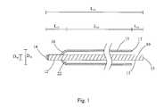
- FIG. 1is an illustration of a longitudinal and end view cross section of a relaxed fiber in a protective member.
- FIG. 2is an illustration of a longitudinal view cross section of an optical fiber configuration having a non-following helical fiber path.
- FIG. 3is an illustration of a longitudinal view cross section of an optical fiber configuration having a non-following sinusoidal fiber path.
- FIG. 4is an illustration of a longitudinal view cross section of a coil of an optical fiber configuration having a non-following path.
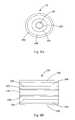
- FIG. 6is an illustration of an end view cross section of a wireline optical fiber configuration.
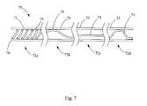
- FIG. 7is an illustration of longitudinal view cross section of an optical fiber configuration having portions having varying non-following fiber paths.
- FIG. 8Ais an illustration of an end view cross section of a fiber.
- FIG. 8Bis an illustration of a longitudinal cross section of the fiber of FIG. 8A .
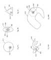
- FIGS. 9A to Care illustrations of end view cross sections of exemplary optical fiber configurations having multiple fibers and substantially convex outer geometries.
- FIGS. 10A to Bare illustrations of end view cross sections of exemplary optical fiber configurations having multiple fibers and substantially concave outer geometries.
- the present inventionsrelate to optical fiber configurations for transmitting laser energy over long distances without substantial loss of power. These inventions further relate to such configurations for transmitting high power laser energy over great distances, and in particular for doing so in harsh environments, while minimizing bending losses that may be brought on by means taken to protect the fibers in such harsh environments.
- FIGS. 1 to 4illustrations of optical fiber configurations.
- an optical fiber 10 and an outer protective member 15e.g., a tube.
- the optical fiber 10has a fiber core and may preferably have a fiber cladding, and a coating, and may also have a protective layer or layers.
- the fiber claddingsurrounds the fiber core, and the coating, if present, surrounds the cladding.
- the fiber coreis preferably circular in cross section.
- the outer protective member 15may be made from any suitable material necessary to meet the requirements of a particular use, based upon various requirements, such as for example temperature, pressure, length, weight and the presence of solvents, other materials, or conditions that could degrade, damage or effect the fiber's ability to transmit laser energy.
- the space 22 between the outer surface of the fiber and the inner surface of the protective membermay further be filled with, or otherwise contain, a gel, an elastomer or some other material, such as a fluid.
- the material, if any, selected for use in the space 22may be selected, among other reasons, to reduce movement or rattling of the fiber in the protective member, to aid in the assembly of the optical fiber configuration, to protect the fiber from mechanical damage, to protect the fiber from thermal damage, to restrain the fiber in a particular configuration, to support the fiber when hanging vertically within the protective member, or other purposes.
- the fiber coremay preferably be composed of fused silica, which preferably has a water content of at most about 0.25 ppm.
- the fiber coremay be composed of other materials, such as those disclosed in U.S. Patent Application Publication No. 2010/0044106, the entire disclosure of which is incorporated herein by reference. Higher purity materials, and the highest purity material available, for use in the fiber core are preferred. This higher purity material minimizes the scattering losses and absorption losses caused by defects and inclusions.
- the fiber coreis about 200 to about 1000 ⁇ m (microns) in diameter or greater, preferably from about 500 to about 700 ⁇ m in diameter and more preferably about 600 ⁇ m in diameter. As used herein the term “about” would include ranges of plus or minus 10%.
- the fiber claddingmay preferably be composed of fluorine doped fused silica.
- the fiber claddingmay be composed of other materials such as fused silica doped with index-altering ions, e.g., germanium, as well as those disclosed in U.S. Patent Application Publication No. 2010/0044106.
- the fiber cladding thicknessdepending upon the wavelength of the laser being used and the fiber core diameter, is from about 50 ⁇ m to about 250 ⁇ m, but could also be substantially thicker, preferably about 40 ⁇ m to about 70 ⁇ m and more preferably about 60 ⁇ m.
- the term “thickness”means the distance between the layer's inner diameter and its outer diameter.
- the thickness of the fiber claddingis dependent upon and relative to the fiber core size and the intended wavelength. In general for 1.1 ⁇ m wavelength the outer diameter of the fiber cladding should be 1.1 ⁇ the outer diameter of core or greater; and, for a 1.5 ⁇ m wavelength the outer diameter of the fiber cladding should be 1.5 ⁇ the outer diameter of the fiber core or greater. Single, as well as, multiple fiber cladding may be utilized. Further, the fiber may have no fiber cladding.
- the coatingis preferably composed of a high temperature acrylate polymer, for higher temperatures a polyimide coating is desirable.
- the coatingmay be composed of other materials, such a metal, as well as those disclosed in U.S. Patent Application Publication No. 2010/0044106.
- the coating thicknessis preferably from about 50 ⁇ m to about 250 ⁇ m, more preferably about 40 ⁇ m to about 150 ⁇ m and more preferably about 90 ⁇ m.
- the coating thicknessmay even be thicker for extreme environments, conditions and special uses or it may be thinner for environments and uses that are less demanding. Further, a hard clad, buffer and other coatings may be used as well.
- the coatingcan be tailored to protect against specific environmental or physical risks to the fiber core and fiber cladding that may be encountered or anticipated in a specific use for the cable.
- the protective layermay be a single layer or multiple layers, thus it may be a first protective layer and a second protective layer, which layers may be the same or different material, or the protective layer may be a single composite layer having different materials. If present, the protective layer surrounds the fiber core (if no fiber cladding and no coating are present), the fiber cladding (if no coating is present), or the coating.
- the protective layermay be a thixotropic gel.
- this layerprimarily protects the fiber from absorption loss from hydroxyl ions as a result of hydrogen migration and protects the fiber from vibration.
- the thixotropic gelprotects the fiber from mechanical damage due to vibrations, as well as, provides support for the fiber when hanging vertically because its viscosity increases when it is static.
- a palladium additivemay be added to the thixotropic gel to provide hydrogen scavenging.
- the hydrogen that diffuses into the fibermay be problematic for germanium or similar ion doped fiber cores. When using a pure silica doped fiber core, it is less of an effect.
- the protective layer(s)may be composed of other materials, such as those disclosed in U.S.
- the thickness of the protective layer(s)should be selected based upon the environment and conditions of use, as well as, the desired flexibility or stiffness of the cable.
- the composition and thickness of the protective layer(s)can be tailored to protect against specific environmental or physical risks to the fiber core, fiber cladding and coating that may be encountered or anticipated in a specific application for the cable.
- the use of the thixotropic gelprovides the dual benefit of adding in the manufacture of the cable, as well as, providing mechanical protection to the fiber core once the cable manufacturing is completed.
- FIGS. 8A and 8BA general illustration of an example of a fiber, having a coating and protective layers, is shown in FIGS. 8A and 8B .
- a fiber 101having a fiber core 100 , a fiber cladding 200 , a coating 300 , a first protective layer 400 and a second protective layer 500 .
- the fiber 101 and the fiber core 100are preferably cylindrical in shape, while the fiber cladding 200 , coating 300 and protective layers 400 and 500 are preferably annular in shape.
- the outer protective membermay preferably be a stainless steel tube composed of 316 stainless steel. If a coating, or a coating and a protective layer, are used with the fiber, the outer protective member would surround those structures. Further, if multiple protective layers are used the outer protective member could constitute one of those layers.
- the outer protective membermay provide physical strength to the fiber over great distances, as well as, protection from physical damage and the environment in which the fiber may be used.
- the outer protective membermay be composed of composite structures, such as, for example, carbon fiber composite tubes.
- the outer protective membermay be composed of other materials, such as those disclosed in U.S. Patent Application Publication No. 2010/0044106.
- the outer protective member thicknessshould be selected based upon the requirements for use and the environment in which the configuration may be used. The thickness may further depend upon the weight and strength of the material from which it is made. Thus, the thickness and composition of the outer protective member can be tailored to protect against specific environmental or physical risks to the fiber core, fiber cladding and coating that may be encountered or anticipated in a specific use for the configuration.
- outer protective membermay be any shape, composition or structure that is suitable or desirable for a particular intended application or use.
- the outer protective membermay be circular, elliptical, rectangular, square or combinations of these shapes, such as, a rectangle having rounded corners, as is seen for example in the tubing manufactured by Canadian Company CJS and sold under the trademark FLATpakTM.
- FIGS. 9A to Cthere is shown outer protective members 915 , 916 and 917 having substantially convex outer geometries.
- protective member 915has a circular outer geometry
- protective member 916has an elliptical outer geometry
- protective member 917has a triangular outer geometry.
- outer protective members 918 and 919having substantially concave outer geometries.
- the outer protective memberdoes not necessarily have to be composed of a single tube or member.
- the outer protective membermay be a composite of materials, such as wound wires or cables, with or without a binding media, as may be seen in the outer structure of wireline used in the oil and drilling industries.
- the outer protective memberneed not be solid, thus a mesh, wire, or coiled structure could be employed.
- the fibermay be packaged in a Teflon® sleeve or equivalent as another means of providing a protective member.
- the outer protective member 15has a total length L 18 and the optical fiber 10 has a total length L 19 .
- the outer protective memberhas a width, which in the case of a circular tube, is its diameter, and has an inner width or diameter D 21 .
- the optical fiberhas an outer width or outer diameter D 20 .
- the outer protective member 15has a first end 16 and a second end 17 .
- the optical fiberhas a first end 14 and a second end 13 . In a relaxed state shown in FIG.
- the fiber ends 14 , 13extend beyond the outer protective member ends 16 , 17 , and thus, fiber section 12 and fiber section 11 extend beyond ends 16 , 17 of the outer protective member 15 by lengths L 12 and L 11 .
- the additional fiber length, when the fiber and protective member ends are coterminous, or substantially coterminous,is taken up and contained within the outer protective member 15 by the fiber 10 having a non-linear, or non-following, path within the outer protective member 15 .
- the terms “non-liner fiber path” and “non-following fiber path,” as used herein,are synonymous and mean that the fiber has additional or different curves, bends or sections than the outer protective member. Examples of configurations where the fiber takes a non-following path with respect to the outer protective member 15 are shown in FIGS. 2 , 3 and 4 .
- FIG. 2there is provided a fiber 10 in which the AFL is taken up by a helical positioning 30 of the fiber within the outer protective member 15 .
- the fiber ends 14 , 13being coterminous with the outer protective member ends 16 , 17 respectively.
- the AFLis this figure would be illustrated by the difference between the total fiber length L 19 and the total outer protective member length L 18 .
- the inner diameter D 21 of the outer protective member 15 and the outer diameter D 20 of the fiber 10There is further shown the inner diameter D 21 of the outer protective member 15 and the outer diameter D 20 of the fiber 10 .
- FIG. 3there is provided a fiber 10 in which the AFL is taken up by a sinusoidal positioning 31 of the fiber within the outer protective member 15 .
- the fiber ends 14 , 13being substantially coterminous with the outer protective member ends 16 , 17 respectively.
- the AFLis this figure would be illustrated by the difference between the total fiber length L 19 and the total outer protective member length L 18 .
- Substantially coterminouswould include small sections of fiber that extend, temporarily or permanently, from one or both ends of the outer protective member 15 that, for example, could be used to attach to a tool, connector, coupler, or other fiber.
- Substantially coterminousin keeping with the spirit of the present invention, is meant to include optical fiber configurations, having fibers extending beyond the ends of the outer protective member in an unrelaxed state, but which obtain the benefits of having AFL, while reducing or eliminating bending losses that prior to the present invention would have been brought on by the presence of such AFL.
- FIG. 3There is further shown in FIG. 3 the inner diameter D 21 of the outer protective member 15 and the outer diameter D 20 of the fiber 10 .
- the length indicator bars, L and D, as well as other features shown in the figuresare for illustrative and qualitative purposes, and are not quantitative or drawn to scale.
- FIG. 4these is show an optical fiber configuration 41 , for example, as if it were coiled around a spool.
- the configurationhas a fiber 10 that has a non-following fiber path 40 , through the outer protective member 15 .
- the additional fiber lengthcan accommodate differences in the thermal rates of expansion between the fiber and the outer protective member. Further, by way of example, the additional fiber length can accommodate the differences in length between the fiber and the outer protective member when the configuration is coiled, e.g., spooled, and uncoiled, e.g., deployed. Moreover, by way of example, the additional fiber length can accommodate the differences in tensile strength and deformation between the fiber and the outer protective member when the configuration is placed under load, i.e., mechanical strain.
- the additional fiber lengthcan, to a greater or lesser extent, fix or hold the fiber in place within the outer protective member, and thus, prevent or restrict the fiber from rattling or vibrating within the outer protective member.
- the additional fiber lengthmay also be partly pulled out of the protective member for attaching tools, fibers, etc., to the end of the fiber, and then, pushed back into the member for protection.
- additional benefits and usesmay be discovered, and such new uses for the present invention form a part of the scope of protection sough herein.
- the presence of additional fiber length in an optical fiber configurationwhen the ends of the fiber and outer protective member are coterminous or substantially conterminous, may have deleterious effects on the ability to transmit laser energy.
- the presence of a non-following fiber pathwhether or not resultant from the presence of additional fiber length, in the optical fiber configuration, may have deleterious effects on the ability to transmit laser energy.
- the deleterious effects of the necessary additional fiber lengthmay range from severe, i.e., substantial power loss, to total power loss, i.e., no laser power is transmitted through the fiber.
- the present inventionsaddress and provide solutions to the problems of bending losses in optical fiber configurations caused by additional fiber length, and in particular provide solutions to the problems of bending losses in fibers having laser power greater than 1 kW, fibers having high laser power, i.e., 5 kW and greater, and in optical fiber configurations of great lengths, i.e., greater than 500 m, while at the same time providing the benefits of and meeting the needs for additional fiber length.
- the additional fiber length for a given fiber in a given outer protective membershould be long enough to address the needs for the additional fiber length in a particular use environment and to obtain any benefits from the presence of the additional fiber length for such use in such environment, while not being so long as to give rise to excess bending losses.
- ⁇ Tis the difference between the average temperature along the length of the configuration that the configuration will reach during an intended use, (AvgTL in use ) and the average temperature along the length of the configuration that the configuration will reach when AFL is determined, e.g., when the optical fiber is assembled into the outer protective member (AvgTL when determined ).
- ⁇ TAvgTL in use ⁇ AvgTL when determined .
- Minimum bend radius of fiberR Fmin [L], where the minimum bend radius is that point at which the macro bending losses exceed the desired dB/km loss for a selected wavelength.
- the presently preferred embodiment of this inventionis in the area of configurations having greater lengths, and in particular, configurations having lengths of about 1 km or greater, between about 1 km and 2 km, from about 5 km to about 7 km and greater.
- configurations having lengthsof about 1 km or greater, between about 1 km and 2 km, from about 5 km to about 7 km and greater.
- R coil [L]for an uncoiled, i.e., essentially straight configuration, would be infinity.
- the outer radius of the fiber, R Fcan range from about 50 ⁇ m to 4 mm or greater.
- the temperature change, ⁇ Tcan range from about ⁇ 273° C. to about 800° C. Higher temperature ranges are possible as higher temperature coatings are developed.
- the mechanical strain, Ecan range from about 0 to about 0.33 of the proof test strength for long term stresses, which for example is 30-40 ksi for a 20 year life time, for shorter time scale applications high stresses could be utilized. Further, compressible outer protective member may be used that could experience compressive mechanical stain and thus in this example the mechanical strain would be negative.
- Formulas 1 to 4For a helical non-following path, such as shown in FIG. 2 , the calculations of Formulas 1 to 4 set forth below can be used to determine the range of excess fiber length available without creating adverse bending losses. Formulas 1 and 2 provide a determination of the maximum AFL as a percentage of total length of the configuration and as a length.
- AFL ⁇ [ % ]mimimum ⁇ ⁇ of ⁇ [ 1 1 ( 1 R Fmin - 1 R coil ) ⁇ ( R OPM - R F ) - 1 + 1 - 1 ⁇ ⁇ or ⁇ 1 1 ( 1 R Fmin - 1 R coil ) ⁇ ( R OPM - R F ) - 1 + 1 - 1 + ( CTE OPM - CTE F ) ⁇ ⁇ ⁇ ⁇ T + ⁇ ]
- Formulas 8 and 9provide a determination of the maximum AFL as a percentage of total length of the configuration and as a length.
- AFL ⁇ [ % ]⁇ minimum ⁇ ⁇ of ⁇ [ F L OPM - 1 ⁇ ⁇ or ⁇ ⁇ F L OPM - 1 + ( CTE OPM - CTE F ) ⁇ ⁇ ⁇ ⁇ T + ⁇ ]
- Formula ⁇ ⁇ 8⁇ AFL ⁇ [ L ] ⁇ AFL ⁇ [ % ] ⁇ L OPM Formula ⁇ ⁇ 9
- Formulas 10 and 11provide a determination of the minimum AFL as a percentage of total length of the configuration and as a length, respectively.
- Formula 10AFL[L] ⁇ AFL[%] ⁇ L OPM Formula 11
- ⁇(dB/km)(power loss that is selected, specified or determined for a loss application)
- nindex of refraction of the core.
- ⁇ carcsin (NA) (where NA is the NA in air)
- ⁇ sys- ln ⁇ [ 2 ⁇ ⁇ 0 ⁇ c ⁇ 1 .95 ⁇ ⁇ tan 2 ⁇ ⁇ c 2 ⁇ e - 2 ⁇ ⁇ tan 2 ⁇ ⁇ tan 2 ⁇ ⁇ c ⁇ e - 2 ⁇ n ⁇ ⁇ k ⁇ ( ⁇ c 2 - ⁇ 2 ) ⁇ e [ - 2 3 ⁇ n ⁇ ⁇ k ⁇ ( R Fmin ⁇ ⁇ c 2 - R Fmin ⁇ ⁇ 2 - 2 ⁇ ⁇ ) ] 3 2 ⁇ ⁇ d ⁇ ]
- Formula 12may be solved for R Fmin .
- examples of optical fiber configurations of the present inventionare configurations of a fiber and outer protective member wherein the AFL[L] of the fiber is between about the lengths obtained from Formulas 9 and 11, or the percentages obtained from Formulas 8 and 10, based upon predetermined selected factors for that use.
- optical fiber configurationfor use in powering a down hole laser tool or laser bottom hole assembly.
- different unitsare provided for different facts, i.e., cm and m. It should be recognized that when applying the various formulas to the factors that the units should be consistent, e.g., all length scales in the same units such as in cm.
- Inner radius of the outer protective member, R OPM1.5 mm (millimeters).
- the AFL[L] for a helical non-following path(for example of the type shown in FIG. 2 ) is from about 3.89 to about 10.4 m; the AFL[%] for a helical non-following path is from about 0.195% to about 0.517%.
- the AFL[L] for a sinusoidal non-following path(for example of the type shown in FIG. 3 ) is from about 3.89 to about 5.38 m; and, the AFL[%] for a sinusoidal non-following path is from about 0.195% to about 0.269%.
- Inner radius of the outer protective member, R OPM3 mm (millimeters).
- the AFL[L] for a helical non-following path(for example of the type shown in FIG. 2 ) is from about 0.245 to about 5.55 m; the AFL[%] for a helical non-following path is from about 0.0245% to about 0.555%.
- the AFL[L] for a sinusoidal non-following path(for example of the type shown in FIG. 3 ) is from about 0.245 to about 3.45 m; and, the AFL[%] for a sinusoidal non-following path is from about 0.0245% to about 0.345%.
- Inner radius of the outer protective member, R OPM1.6 mm (millimeters).
- the AFL[L] for a helical non-following path(for example of the type in FIG. 2 ) is from about 4.42 to about 18.2 m; the AFL[%] for a helical non-following path is from about 0.147% to about 0.61%.
- the AFL[L] for a sinusoidal non-following path(for example of the type shown in FIG. 3 ) is from about 4.42 to about 11.4 m; and, the AFL[%] for a sinusoidal non-following path is from about 0.147% to about 0.3792%.
- Inner radius of the outer protective member, R OPM10 mm (millimeters).
- L OPM0.5 km.
- the AFL[L] for a helical non-following path(for example of the type shown in FIG. 2 ) is from about 0 to about 10 m; the AFL[%] for a helical non-following path is from about 0% to about 2%.
- the AFL[L] for a sinusoidal non-following path(for example of the type shown in FIG. 3 ) is from about 0 to about 4.88 m; and, the AFL[%] for a sinusoidal non-following path is from about 0% to about 0.976%.
- the optical fiber configurationscan be greater than about 0.5 km (kilometer), greater than about 1 km, greater than about 2 km, greater than about 3 km, greater than about 4 km and greater than about 5 km and between 1 km and 5 km and between 1 km and 20 km.
- the length of the configurationrefers to the length when the fiber end and the outer protective end are substantially coterminous.
- the preferred fibers using the preferred optical fiber configurationscan withstand temperatures of up to about 200° C. to about 300° C., pressures of up to about 3000 psi and as great as 36,000 psi, and corrosive environments over the length of the fiber without substantial loss of power and for extended periods of time.
- the optical fibercan have a power loss, for a given wavelength, of less then about 3.0 dB/km, less than about 2.0 dB/km, less than about 1.5 dB/km, less than about 1.0 dB/km, less than about 0.5 dB/km and less than about 0.3 dB/km.
- the optical fiber configurationscan have power transmissions of at least about 50%, at least about 60%, at least about 80%, and at least about 90%.
- any type of high power lasermay be used as a source of laser energy for use with the optical fiber configurations of the present invention.
- Examples of such lasersare disclosed in U.S. Patent Application Publication No. 2010/0044106, the disclosure of which is incorporated herein by reference.
- High power infrared lasersare preferable. Wavelengths of about 1490 nm, about 1550 nm, and about 1080 nm have even greater potential benefits. Further, broadband beams within these wavelength ranges may have greater benefits.
- the lasershould generate a laser beam in the infrared wavelength having a power of at least about 1 kW, at least about 3 kW, at least about 5 kW, at least about 10 kW, and at least about 20 kW or greater.
- a preferred laser for use with the optical fiber configurations of the present inventionis ytterbium fiber laser such as the IPG YLR-20000.
- the detailed properties of this laserare disclosed in U.S. Patent Application Publication No. 2010/0044106.
- the preferred laserincludes 20 modules.
- the gain bandwidth of a fiber laseris on the order of 20 nm
- the linewidth of the free oscillatoris 3 nm
- Full Width Half Maximum (FWHM)may range from 3 nm to 5 nm (although higher linewidths including 10 nm are envisioned and contemplated).
- Each module's wavelengthis slightly different.
- the modulesfurther each create a multi-mode beam.
- the cumulative effect of combining the beams from the modulesis to maintain the Raman gain and the Brillouin gain at a lower value corresponding to the wavelengths and linewidths of the individual modules, and thus, consequently reducing the SBS and SRS phenomenon in the fiber when the combined beams are transmitted through the fiber.
- FIG. 5illustrates a wireline 50 having two layers of helically wound armor wires, an outer layer 51 and an inner layer 52 .
- Other types and arrangement of wirelinesare know to those of skill in the art.
- the space 58 between the outer surface of the fiber and the inner surface of the protective membermay further be filled with, or otherwise contain, a gel, an elastomer or some other material, such as a fluid.
- a second space 59may further be filled with, or otherwise contain, a gel, an elastomer or some other material, such as a fluid, which material will prevent the armor wires from crushing inwardly from external pressure of an application, such as the pressure found in a well bore.
- the fibermay be packaged in a Teflon® sleeve or equivalent type of material or sleeve.
- FIG. 6illustrates a wireline 60 having outer armor wire layer 61 and inner armor wire layer 62 .
- the wireline 60constitutes an optical fiber configuration having a fiber 65 and an outer protective member 66 .
- the space 69 between the fiber 65 and the armor wire layer 62may further be filled with, or otherwise contain, a gel, an elastomer or some other material, such as a fluid, which material will prevent the armor wires from crushing inwardly from external pressure of an application, such as the pressure found in a well bore.
- line structureshould be given its broadest construction, unless specifically stated otherwise, and would include without limitation, wireline, coiled tubing, logging cable, cable structures used for completion, workover, drilling, seismic, sensing logging and subsea completion and other subsea activities, scale removal, wax removal, pipe cleaning, casing cleaning, cleaning of other tubulars, cables used for ROV control power and data transmission, lines structures made from steal, wire and composite materials such as carbon fiber, wire and mesh, line structures used for monitoring and evaluating pipeline and boreholes, and would include without limitation such structures as Power & Data Composite Coiled Tubing (PDT-COIL) and structures such as Smart Pipe®.
- PDT-COILPower & Data Composite Coiled Tubing
- Smart Pipe®Smart Pipe®.
- the optical fiber configurationscan be used in conjunction with, in association with, or as part of a line structure.
- FIG. 7illustrates an optical fiber configuration 70 having a fiber 74 , an outer protective member 75 and portions 72 of the fiber each portion having a length and differing fiber paths, 72 a , 72 b , 72 c , and 72 d .
- Fiber paths 72 a , 72 b and 72 dare non-following paths, while path 72 c is a following path.
- Path 72 ais a helical type of non-following path.
- Paths 72 b and 72 dare sinusoidal types of non-following paths.
- the optical fiber configuration 70has ends 76 , wherein it shown that the fiber is conterminous with the outer protective member. The fibers in these sections may have different or the same diameters.
- the fiberis of the type shown in FIG. 7 , having a first section having a helical non-following fiber path, a second section having following fiber path, and a third section having a sinusoidal non-following fiber path.
- the entire configuration and its sectionwould have the following values, factors and AFLs, which are set out in Table I.
- FIGS. 9A to 9Cthere is shown optical fiber configurations having outer protective members 915 , 916 and 917 having substantially convex outer geometries.
- protective member 915has a circular outer geometry
- protective member 916has an elliptical outer geometry
- protective member 917has a triangular outer geometry.
- these configurations of FIGS. 9A to 9Chave fiber bundles 921 , 922 and 923 , which bundles have multiple fibers.
- bundle 922has fibers of different diameters.
- FIGS. 10A and 10Bthere is further shown optical fiber configurations having extreme examples, for illustrative purposes, of outer protective members 918 and 919 having substantially concave outer geometries.
- These configurations of FIGS. 10A and 10Bhave fiber bundles 924 and 925 . The fibers in these bundles may also be of different diameters.
- the forgoing formulas 1 to 12can be used to determine AFL, for the types of configurations shown in FIGS. 9A-C and 10 A-B, with the following modification to the definitions of the factors for the inner radius of the outer protective member, R OPM , and the outer radius of the fiber, R F .
- R OPMwill be the minimum distance from a member of the fiber bundle to the outer protective member, when the moment of inertia of the bundle is located at the center of the largest circle that can be inscribed within the outer protective member, plus the radius of the smallest diameter fiber in the bundle.
- the R Fis the radius of the smallest diameter fiber in the bundle.
- the largest circle that can be inscribedwould be the inner diameter of the outer protective member 915 , i.e., the largest circle would be concentric with the inner diameter of the outer protective member 915 .
- the R OPM for the configuration of FIG. 9Bwould be determined as follows.
- the largest circle 940 that can be inscribed within the internal diameter of the outer protective member 916is determined.
- the center 950 of the largest circle 940is determined.
- the moment of inertia 960 of the bundle 922is determined.
- the fiber bundle 922 and the largest circle 940are then for computational purposes centered by aligning the circle center 950 and the moment of inertia 960 .
- the R OPMis then equal to the smallest distance between the computationally centered fiber bundle (i.e., when moment 960 and center 950 are aligned) and the outer protective member 916 , plus the radius of the smallest diameter fiber in the bundle.
- the R OPM for the configuration of FIG. 10Awould be determined as follows.
- the largest circle 942 that can be inscribed within the internal diameter of the outer protective member 918is determined.
- the center 952 of the largest circle 942is determined.
- the moment of inertia 962 of the bundle 924is determined.
- the fiber bundle 924 and the largest circle 942are then for computational purposes centered by aligning the circle center 952 and the moment of inertia 962 .
- the R OPMis then equal to the smallest distance between the computationally centered fiber bundle (i.e., when moment 962 and center 952 are aligned) and the outer protective member 918 plus the radius of the smallest diameter fiber in the bundle.
- R OPMfor the configuration of FIG. 10B would be determined as follows.
- the largest circle 943 that can be inscribed within the internal diameter of the outer protective member 919is determined.
- the center 953 of the largest circle 943is determined.
- the moment of inertia 963 of the bundle 925is determined.
- the fiber bundle 925 and the largest circle 943are then for computational purposes centered by aligning the circle center 953 and the moment of inertia 963 .
- R OPMis equals to the smallest distance between the computationally centered fiber bundle (i.e., when moment 963 and center 953 are aligned) and the outer protective member 919 , plus the radius of the smallest diameter fiber in the bundle.
Landscapes
- Physics & Mathematics (AREA)
- General Physics & Mathematics (AREA)
- Optics & Photonics (AREA)
- Lasers (AREA)
- Light Guides In General And Applications Therefor (AREA)
Abstract
Description
This invention was made with Government support under Award DE-AR0000044 awarded by the Office of ARPA-E U.S. Department of Energy. The Government has certain rights in this invention.
1. Field of the Invention
The present invention relates to configurations of optical fibers that provide the ability to assemble, spool and unspool, deploy or use such configurations, while maintaining the fiber's ability to transmit laser energy over distances, and in particular, over great distance and at high powers. The present invention further relates to configurations that are strengthened to withstand harsh environments, such as the environments found in a borehole, a nuclear plant, or under the sea. In particular, the present invention relates to unique and novel configurations utilizing additional fiber length to minimize bending losses while providing benefits for selected predetermined applications.
As used herein, unless specified otherwise “high power laser energy” means a laser beam having at least about 5 kW (kilowatt) of power. As used herein, unless specified otherwise “great distances” means at least about 500 m (meter). As used herein the term “substantial loss of power,” “substantial power loss” and similar such phrases, mean a loss of power of more than about 3.0 dB/km (decibel/kilometer) for a selected wavelength. As used herein the term “substantial power transmission” means at least about 50% transmittance.
2. Discussion of Related Art
Until the development of the inventions set forth in patent application Ser. No. 12/706,576, pending, filed Feb. 16, 2010, the entire disclosure of which is incorporated herein by reference, it was believed that the transmission of high power laser energy over great distances without substantial loss of power was unobtainable. As a consequence, prior to the inventions of that patent application it was further believed that there was no reason to construct, or investigate the composition of, an optical fiber, an optical fiber configuration, or an optical fiber cable for the transmission of high power laser energy over great distances.
Power loss over long distances occurs in an optical fiber from many sources including: absorption loss, and in particular absorption loss from hydroxyl ions (OH−); Rayleigh scattering; Brillouin scattering; Raman scattering; defects; inclusions; and bending loss. These problems have been documented in the literature.
An example of the prior belief in the art that a paradigm existed between the transmission of high power laser energy over great distances and substantial power loss, is illustrated in the article by Muto et al., titled “Laser cutting for thick concrete by multi-pass technique,” CHINESE OPTICS LETTERS Vol. 5, Supplement May 31, 2007, pages S39-S41 (hereinafter referred to as “Muto”). Although Muto states that 4 kW of power were delivered down a 1 km fiber, when 5 kW of laser power was put into the fiber, Muto fails to eliminate the stimulated Raman scattering (“SRS”) phenomena. As shown by Muto's paper this deleterious phenomenon will effectively clamp the output power as length or power is increased. The SRS phenomenon is shown by the spectrum in FIG. 3 of Muto. Thus, prior to the invention of Ser. No. 12/706,576, it was believed that as input laser power, or the length of the fiber increased, the power output of a fiber would not increase because of the stimulated Brillouin scattering (“SBS”), SRS and other nonlinear phenomena. In particular, SBS would transfer the output power back up the fiber toward the input. Further, SBS, SRS, as well as the other deleterious nonlinear effects, in addition to limiting the amount of power that can be transmitted out of the fiber, can result in fiber heating and ultimate failure. Thus, as recognized by Muto, at page S41 “[i]t is found that 10-kW-power delivery is feasible through a 250-m-long fiber with the core diameter of 150 μm. The physical phenomenon which restricts the transmitted power is SRS.” Thus, Muto, as did others before him, failed to deliver high power laser energy over great distances.
Further, Muto does not disclose, discuss or address the placing of its optical fiber in any protective tubing or material, the coiling and uncoiling of its fiber or the strengthening of its fiber for use in a particular application. In particular, Muto does not address the bending losses associated with such configurations and, in particular, the bending losses that are associated with strengthened configurations.
The present invention provides solutions to bending loss problems that are associated with configuring optical fibers in protective structures and, in particular, in placing long lengths of high power optical fibers in protective tubing and then coiling and uncoiling such a configuration. Various solutions, examples of which are provided in this specification, are provided for minimizing, and in certain instances eliminating to any practical extent, bending losses that result from such configurations.
The present invention advances the art of laser delivery, and in particular the art of high power laser delivery, by providing an optical fiber configuration that avoids or mitigates the bending losses associated with optical fiber configurations and, in particular, provides an optical fiber configuration for the transmission of high power laser energy over great distances in harsh environments without substantial power loss.
It is desirable to have an optical fiber configuration that provides for the delivery of laser energy and in particular high power laser energy over great distances and without substantial power loss, in particular losses from bending. The present invention, among other things, solves these needs by providing the articles of manufacture, devices and processes taught herein.
Thus, there is provided an optical fiber configuration for transmitting laser energy over great distances for use in an application, the optical fiber configuration having an optical fiber, that has a first end, a second end, a length (LF) defined between the first and second optical fiber ends, and a fiber core, wherein the optical fiber has an outer radius (RF), a coefficient of thermal expansion (CTEF), and a minimum bend radius (RFmin). The configuration also has an outer protective member around the optical fiber, which has a first end, a second end, and a length (LOPM) defined between the first and second outer protective member ends at ambient temperature and with no mechanical strain, wherein the outer protective member has an inner radius (ROPM), a coefficient of thermal expansion (CTEOPM), and the ROPMis greater than the RF. In this configuration, the first and second ends of the outer protective member and the first and second ends of the optical fiber are substantially coterminous; the optical fiber configuration has a predetermined temperature range (ΔT), a predetermined mechanical strain (ε), and a predetermined inner radius of coil (Rcoil); and the LFis greater than the LOPM, so that LF−LOPM=AFL (additional fiber length). In this configuration the optical fiber takes a helical non-following path within the outer protective member; and, the AFL is equal to or between at least one of: an AFL[L] from Formulas 2 and 4; or an AFL[%] from Formulas 1 and 3, which formulas are set forth herein.
There is further provided an optical fiber configuration for transmitting laser energy over great distances, having an optical fiber, which has a first end, a second end, a length (LF) defined between the first and second optical fiber ends, and a fiber core, wherein the optical fiber has an outer radius (RF), a coefficient of thermal expansion (CTEF), and a minimum bend radius (RFmin). This configuration further has an outer protective member around the optical fiber, the outer protective member has a first end, a second end, and a length (LOPM) between the first and second outer protective member ends at ambient temperature and with no mechanical strain, wherein the outer protective member has an inner radius (ROPM), a coefficient of thermal expansion (CTEOPM), and the ROPMis greater than the RF. The configuration is further characterized in that the first and second ends of the outer protective member and the first and second ends of the optical fiber are substantially coterminous; wherein the optical fiber configuration has a predetermined temperature range (ΔT), a predetermined mechanical strain (ε), and a predetermined inner radius of coil (Rcoil); and wherein the LFis greater than the LOPM, so that LF−LOPM=AFL (additional fiber length). In this configuration the optical fiber takes on a sinusoidal non-following path within the outer protective member; and, the AFL is equal to or between at least one of: an AFL[L] fromFormulas 9 and 11; or an AFL[%] fromFormulas 8 and 10, set forth herein.
There is additionally provided an optical fiber configuration for transmitting laser energy over great distances for use in an application, having an optical fiber, a portion of which has a first end, a second end, a length (LF) defined between the first and second optical fiber ends, and a fiber core, wherein the optical fiber has an outer radius (RF), a coefficient of thermal expansion (CTEF), and a minimum bend radius (RFmin). This configuration further has an outer protective member around the optical fiber portion, a portion of the outer protective member comprising a first end, a second end, and a length (LOPM) defined between the first and second outer protective member ends at ambient temperature and with no mechanical strain, wherein the outer protective member has an inner radius (ROPM), a coefficient of thermal expansion (CTEOPM), and the ROPMis greater than the RF. The configuration is characterized by the first and second ends of the outer protective member and the first and second ends of the optical fiber are substantially coterminous or being coterminous, which would be include as substantially coterminous. This configuration has has a predetermined temperature range (ΔT), a predetermined mechanical strain (ε), and a predetermined inner radius of coil (Rcoil); wherein the LFis greater than the LOPM, so that LF−LOPM=AFL (additional fiber length). It further has the optical fiber taking a helical non-following path within the outer protective member; and, the AFL is equal to or between at least one of: an AFL[L] from Formulas 2 and 4; or an AFL[%] from Formulas 1 and 3 set forth herein. This optical fiber configuration is capable of transmitting at least about 1 kW, about 2 kW, and about 10 kW of laser energy over great distances without substantial bending losses.
There is also provided an optical fiber configuration for transmitting laser energy over great distances for use in an application, having an optical fiber, a portion of the fiber comprising a first end, a second end, a length (LF) defined between the first and second optical fiber ends, and a fiber core, wherein the optical fiber has an outer radius (RF), a coefficient of thermal expansion (CTEF), and a minimum bend radius (RFmin). The configuration further having an outer protective member around the optical fiber portion, a portion of the outer protective member comprising a first end, a second end, and a length (LOPM) between the first and second outer protective member ends at ambient temperature and with no mechanical strain, wherein the outer protective member has an inner radius (ROPM), a coefficient of thermal expansion (CTEOPM), and the ROPMis greater than the RF. In this configuration the first and second ends of the outer protective member and the first and second ends of the optical fiber are substantially coterminous; wherein the optical fiber configuration has a predetermined temperature range (ΔT), a predetermined mechanical strain (ε), and a predetermined inner radius of coil (Rcoil); and wherein the LFis greater than the LOPM, so that LF−LOPM=AFL (additional fiber length). In this configuration the optical fiber takes a sinusoidal non-following path within the outer protective member; and the AFL is equal to or between at least one of: an AFL[L] fromFormulas 9 and 11; or an AFL[%] fromFormulas 8 and 10 set forth herein. This optical fiber configuration is capable of transmitting at least about 1 kW, of about 2 kW or about 10 kW of laser energy over great distances without substantial bending losses.
Additionally, there is provided an optical fiber configuration for reducing bending losses for use in an application, which has an optical fiber that has a fiber core, the fiber core having a diameter of at least about 100 μm, an outer protective member in association with the optical fiber, and a means for simultaneously providing a benefit of additional fiber length while minimizing the bending losses associated with additional fiber length. In this configuration there may further be a plurality of optical fibers and wherein the outer protective member has a substantially convex outer geometry, or a plurality of optical fibers and wherein the outer protective member has a substantially concave outer geometry. These configurations may still further be capable of transmitting laser energy greater than about 5 kW, over distances greater than about 1 km without substantial power loss and may yet still further be capable of transmitting laser energy greater than about 10 kW, over distances greater than about 1 km without substantial power loss.
In these configurations provided herein the additional fiber length benefits may be, among others, separate or combined: accommodating the coiling and uncoiling of the configuration; accommodating a difference in tensile strength between the optical fiber and the outer protective member; accommodating a difference in deformation between the optical fiber and the outer protective member; accommodating a difference in deformation between the optical fiber and the outer protective member brought about by thermal factors; holding or affixing the optical fiber within the outer protective member; providing an attachment point, or section, for attaching tools, fibers, couplers, or connectors to the optical fiber; and, reducing rattling of the optical fiber within the outer protective member.
There is also provided methods for making the optical fiber configurations provided herein, which methods include selecting a value for an inner radius of the outer protective member, ROPM, selecting a value for an outer radius of the fiber, RF. selecting a value for a temperature change that the configuration is capable of withstanding, ΔT; selecting a value for a mechanical strain that the configuration is capable of withstanding, ε; selecting a value for the coefficient of thermal expansion of the fiber, CTEF; selecting a value for a coefficient of thermal expansion of the outer protective member, CTEOPM; selecting a value for a length of outer protective member at ambient temperature and no mechanical strain, LOPM; selecting a value for a minimum bend radius of the fiber, RFmin; selecting a value for an inner radius of a coil of the configuration, Rcoil; selecting that the fiber will have a non-following path that may be helical, sinusoidal or combinations thereof, within the outer protective member; and, using these determined values to select a maximum AFL[L] and a minimum AFL[L] using the formulas provided herein and making the optical fiber configuration in accordance with the determined maximum and minimum AFL[L]s, such that the total fiber length is between the maximum and minimum determined AFL[L]s.
Still further there is provided an optical fiber configuration for transmitting laser energy over great distances for use in an application, the optical fiber configuration comprising: an optical fiber, the optical fiber comprising a first end, a second end, and a length (LF) defined between the first and second optical fiber ends that is greater than approximately 500 m, an outer protective member around the optical fiber, the outer protective member comprising a first end, a second end, and a length (LOPM) defined between the first and second outer protective member ends; wherein the LF is greater than the LOPM ; and the optical fiber and outer protective member configured so that when high power laser energy is directed from the first optical fiber end to the second fiber end there is not substantial loss of power of the high power laser energy at the second optical fiber end when compared with initial power of the high power laser energy entering the first optical fiber end. This optical fiber configuration may further have configurations in which the first and second ends of the outer protective member and the first and second ends of the optical fiber are substantially coterminous; wherein the optical fiber takes a helical non-following path within the outer protective member; wherein the optical fiber takes a helical non-following path within the outer protective member; wherein the optical fiber takes a sinusoidal non-following path within the outer protective member; and, wherein the optical fiber takes a sinusoidal non-following path within the outer protective member.
In general, the present inventions relate to optical fiber configurations for transmitting laser energy over long distances without substantial loss of power. These inventions further relate to such configurations for transmitting high power laser energy over great distances, and in particular for doing so in harsh environments, while minimizing bending losses that may be brought on by means taken to protect the fibers in such harsh environments.
Thus, in general, and by way of illustrative examples, there are provided inFIGS. 1 to 4 illustrations of optical fiber configurations. In these figures like numbers have like meaning. Thus, there is provided anoptical fiber 10 and an outerprotective member 15, e.g., a tube.
Theoptical fiber 10 has a fiber core and may preferably have a fiber cladding, and a coating, and may also have a protective layer or layers. The fiber cladding surrounds the fiber core, and the coating, if present, surrounds the cladding. The fiber core is preferably circular in cross section. The outerprotective member 15 may be made from any suitable material necessary to meet the requirements of a particular use, based upon various requirements, such as for example temperature, pressure, length, weight and the presence of solvents, other materials, or conditions that could degrade, damage or effect the fiber's ability to transmit laser energy. Thespace 22 between the outer surface of the fiber and the inner surface of the protective member, may further be filled with, or otherwise contain, a gel, an elastomer or some other material, such as a fluid. The material, if any, selected for use in thespace 22 may be selected, among other reasons, to reduce movement or rattling of the fiber in the protective member, to aid in the assembly of the optical fiber configuration, to protect the fiber from mechanical damage, to protect the fiber from thermal damage, to restrain the fiber in a particular configuration, to support the fiber when hanging vertically within the protective member, or other purposes.
The fiber core may preferably be composed of fused silica, which preferably has a water content of at most about 0.25 ppm. The fiber core may be composed of other materials, such as those disclosed in U.S. Patent Application Publication No. 2010/0044106, the entire disclosure of which is incorporated herein by reference. Higher purity materials, and the highest purity material available, for use in the fiber core are preferred. This higher purity material minimizes the scattering losses and absorption losses caused by defects and inclusions. The fiber core is about 200 to about 1000 μm (microns) in diameter or greater, preferably from about 500 to about 700 μm in diameter and more preferably about 600 μm in diameter. As used herein the term “about” would include ranges of plus or minus 10%.
The fiber cladding may preferably be composed of fluorine doped fused silica. The fiber cladding may be composed of other materials such as fused silica doped with index-altering ions, e.g., germanium, as well as those disclosed in U.S. Patent Application Publication No. 2010/0044106. The fiber cladding thickness, depending upon the wavelength of the laser being used and the fiber core diameter, is from about 50 μm to about 250 μm, but could also be substantially thicker, preferably about 40 μm to about 70 μm and more preferably about 60 μm. As used herein with respect to a multi-layer structure, the term “thickness” means the distance between the layer's inner diameter and its outer diameter. The thickness of the fiber cladding is dependent upon and relative to the fiber core size and the intended wavelength. In general for 1.1 μm wavelength the outer diameter of the fiber cladding should be 1.1× the outer diameter of core or greater; and, for a 1.5 μm wavelength the outer diameter of the fiber cladding should be 1.5× the outer diameter of the fiber core or greater. Single, as well as, multiple fiber cladding may be utilized. Further, the fiber may have no fiber cladding.
The coating is preferably composed of a high temperature acrylate polymer, for higher temperatures a polyimide coating is desirable. The coating may be composed of other materials, such a metal, as well as those disclosed in U.S. Patent Application Publication No. 2010/0044106. The coating thickness is preferably from about 50 μm to about 250 μm, more preferably about 40 μm to about 150 μm and more preferably about 90 μm. The coating thickness may even be thicker for extreme environments, conditions and special uses or it may be thinner for environments and uses that are less demanding. Further, a hard clad, buffer and other coatings may be used as well. The coating can be tailored to protect against specific environmental or physical risks to the fiber core and fiber cladding that may be encountered or anticipated in a specific use for the cable.
The protective layer, if present, may be a single layer or multiple layers, thus it may be a first protective layer and a second protective layer, which layers may be the same or different material, or the protective layer may be a single composite layer having different materials. If present, the protective layer surrounds the fiber core (if no fiber cladding and no coating are present), the fiber cladding (if no coating is present), or the coating.
The protective layer may be a thixotropic gel. In one of the preferred embodiments, this layer primarily protects the fiber from absorption loss from hydroxyl ions as a result of hydrogen migration and protects the fiber from vibration. The thixotropic gel protects the fiber from mechanical damage due to vibrations, as well as, provides support for the fiber when hanging vertically because its viscosity increases when it is static. A palladium additive may be added to the thixotropic gel to provide hydrogen scavenging. The hydrogen that diffuses into the fiber may be problematic for germanium or similar ion doped fiber cores. When using a pure silica doped fiber core, it is less of an effect. The protective layer(s) may be composed of other materials, such as those disclosed in U.S. Patent Application Publication No. 2010/0044106. The thickness of the protective layer(s) should be selected based upon the environment and conditions of use, as well as, the desired flexibility or stiffness of the cable. Thus, the composition and thickness of the protective layer(s) can be tailored to protect against specific environmental or physical risks to the fiber core, fiber cladding and coating that may be encountered or anticipated in a specific application for the cable. Further, the use of the thixotropic gel provides the dual benefit of adding in the manufacture of the cable, as well as, providing mechanical protection to the fiber core once the cable manufacturing is completed.
A general illustration of an example of a fiber, having a coating and protective layers, is shown inFIGS. 8A and 8B . Thus, there is provided afiber 101, having afiber core 100, afiber cladding 200, acoating 300, a firstprotective layer 400 and a secondprotective layer 500. Thefiber 101 and thefiber core 100 are preferably cylindrical in shape, while thefiber cladding 200, coating300 andprotective layers
The outer protective member may preferably be a stainless steel tube composed of 316 stainless steel. If a coating, or a coating and a protective layer, are used with the fiber, the outer protective member would surround those structures. Further, if multiple protective layers are used the outer protective member could constitute one of those layers.
The outer protective member, for example the outerprotective member 15 shown inFIGS. 1 to 4 , may provide physical strength to the fiber over great distances, as well as, protection from physical damage and the environment in which the fiber may be used. In addition to metal, the outer protective member may be composed of composite structures, such as, for example, carbon fiber composite tubes. The outer protective member may be composed of other materials, such as those disclosed in U.S. Patent Application Publication No. 2010/0044106. The outer protective member thickness should be selected based upon the requirements for use and the environment in which the configuration may be used. The thickness may further depend upon the weight and strength of the material from which it is made. Thus, the thickness and composition of the outer protective member can be tailored to protect against specific environmental or physical risks to the fiber core, fiber cladding and coating that may be encountered or anticipated in a specific use for the configuration.
Further the outer protective member may be any shape, composition or structure that is suitable or desirable for a particular intended application or use. Thus, for example the outer protective member may be circular, elliptical, rectangular, square or combinations of these shapes, such as, a rectangle having rounded corners, as is seen for example in the tubing manufactured by Canadian Company CJS and sold under the trademark FLATpak™. For example, inFIGS. 9A to C there is shown outerprotective members protective member 916 has an elliptical outer geometry andprotective member 917 has a triangular outer geometry. InFIGS. 10A and B there is further shown extreme examples, for illustrative purposes, of outerprotective members
Turning to the configurations illustrated inFIGS. 1 to 4 the outerprotective member 15 has a total length L18and theoptical fiber 10 has a total length L19. The outer protective member has a width, which in the case of a circular tube, is its diameter, and has an inner width or diameter D21. The optical fiber has an outer width or outer diameter D20. The outerprotective member 15 has afirst end 16 and asecond end 17. The optical fiber has afirst end 14 and asecond end 13. In a relaxed state shown inFIG. 1 , i.e., for practical purposes no forces restraining or affixing the fiber to the protective member, the fiber ends14,13 extend beyond the outer protective member ends16,17, and thus,fiber section 12 andfiber section 11 extend beyond ends16,17 of the outerprotective member 15 by lengths L12and L11. This additional length of fiber (L12, L11), which in this example of a relaxed state extends beyond the ends of the outer protective member, is the additional fiber length (“AFL”) that is present in the configuration, i.e., the difference in total length between the length L18of the outer protective member and the total length L19of the fiber (i.e., AFL=L11+L12=L19−L18).
In the optical fiber configurations of the present inventions, as shown by way of example inFIGS. 2 to 4 , the additional fiber length, when the fiber and protective member ends are coterminous, or substantially coterminous, is taken up and contained within the outerprotective member 15 by thefiber 10 having a non-linear, or non-following, path within the outerprotective member 15. The terms “non-liner fiber path” and “non-following fiber path,” as used herein, are synonymous and mean that the fiber has additional or different curves, bends or sections than the outer protective member. Examples of configurations where the fiber takes a non-following path with respect to the outerprotective member 15 are shown inFIGS. 2 ,3 and4.
InFIG. 2 there is provided afiber 10 in which the AFL is taken up by ahelical positioning 30 of the fiber within the outerprotective member 15. In this figure there is illustrated the fiber ends14,13 being coterminous with the outer protective member ends16,17 respectively. The AFL is this figure would be illustrated by the difference between the total fiber length L19and the total outer protective member length L18. There is further shown the inner diameter D21of the outerprotective member 15 and the outer diameter D20of thefiber 10.
InFIG. 3 there is provided afiber 10 in which the AFL is taken up by asinusoidal positioning 31 of the fiber within the outerprotective member 15. In this figure there is illustrated the fiber ends14,13 being substantially coterminous with the outer protective member ends16,17 respectively. The AFL is this figure would be illustrated by the difference between the total fiber length L19and the total outer protective member length L18. Substantially coterminous would include small sections of fiber that extend, temporarily or permanently, from one or both ends of the outerprotective member 15 that, for example, could be used to attach to a tool, connector, coupler, or other fiber. Substantially coterminous, in keeping with the spirit of the present invention, is meant to include optical fiber configurations, having fibers extending beyond the ends of the outer protective member in an unrelaxed state, but which obtain the benefits of having AFL, while reducing or eliminating bending losses that prior to the present invention would have been brought on by the presence of such AFL. There is further shown inFIG. 3 the inner diameter D21of the outerprotective member 15 and the outer diameter D20of thefiber 10.
The length indicator bars, L and D, as well as other features shown in the figures are for illustrative and qualitative purposes, and are not quantitative or drawn to scale.
InFIG. 4 these is show anoptical fiber configuration 41, for example, as if it were coiled around a spool. The configuration has afiber 10 that has anon-following fiber path 40, through the outerprotective member 15.
There are several benefits and needs for having additional fiber length in an optical fiber configuration. For example, the additional fiber length can accommodate differences in the thermal rates of expansion between the fiber and the outer protective member. Further, by way of example, the additional fiber length can accommodate the differences in length between the fiber and the outer protective member when the configuration is coiled, e.g., spooled, and uncoiled, e.g., deployed. Moreover, by way of example, the additional fiber length can accommodate the differences in tensile strength and deformation between the fiber and the outer protective member when the configuration is placed under load, i.e., mechanical strain. Additionally, by way of example, the additional fiber length can, to a greater or lesser extent, fix or hold the fiber in place within the outer protective member, and thus, prevent or restrict the fiber from rattling or vibrating within the outer protective member. The additional fiber length may also be partly pulled out of the protective member for attaching tools, fibers, etc., to the end of the fiber, and then, pushed back into the member for protection. As the present inventions becomes known to those of skill in the art, additional benefits and uses may be discovered, and such new uses for the present invention form a part of the scope of protection sough herein. These, as well as other, benefits and needs for additional fiber length, in particular for high power long distance optical fiber configurations, can, as illustrated herein, be determined, selected and specified for a particular application, use, environment or deployment.
However, the presence of additional fiber length in an optical fiber configuration, when the ends of the fiber and outer protective member are coterminous or substantially conterminous, may have deleterious effects on the ability to transmit laser energy. Similarly, the presence of a non-following fiber path, whether or not resultant from the presence of additional fiber length, in the optical fiber configuration, may have deleterious effects on the ability to transmit laser energy. In particular as laser power increases and the length of the configuration increases the deleterious effects of the necessary additional fiber length may range from severe, i.e., substantial power loss, to total power loss, i.e., no laser power is transmitted through the fiber. These deleterious effects are caused by bending losses that occur when the fiber takes a non-following path within the outer protective member or when the fiber is coiled too tightly.
The present inventions address and provide solutions to the problems of bending losses in optical fiber configurations caused by additional fiber length, and in particular provide solutions to the problems of bending losses in fibers having laser power greater than 1 kW, fibers having high laser power, i.e., 5 kW and greater, and in optical fiber configurations of great lengths, i.e., greater than 500 m, while at the same time providing the benefits of and meeting the needs for additional fiber length. Thus, the additional fiber length for a given fiber in a given outer protective member should be long enough to address the needs for the additional fiber length in a particular use environment and to obtain any benefits from the presence of the additional fiber length for such use in such environment, while not being so long as to give rise to excess bending losses.
Thus, the following factors as applied to the novel aspects of the present invention provide optical fiber configurations that have the requisite additional fiber length while minimizing or preventing bending losses in that configuration from the additional fiber length taking a non-following path. Predetermined values for these factors would be selected or determined for a particular application, use, environment or deployment. These factors are defined as follows:
Inner radius of the outer protective member=ROPM[L] where [L] is a unit of length, such as meters.
Outer radius of the optical fiber (including cladding and coating, if present)=RF[L].
Temperature change, i.e., temperature range, that the configuration must sustain in the intend use=ΔT [T], where [T] is a unit of temperature, such as degrees centigrade. ΔT is the difference between the average temperature along the length of the configuration that the configuration will reach during an intended use, (AvgTLin use) and the average temperature along the length of the configuration that the configuration will reach when AFL is determined, e.g., when the optical fiber is assembled into the outer protective member (AvgTLwhen determined). Thus, ΔT=AvgTLin use−AvgTLwhen determined.
Mechanical strain that the configuration must sustain in the intend use =ε.
Coefficient of thermal expansion of the fiber=CTEF[1/T].
Coefficient of thermal expansion of the outer protective member=CTEOPM[1/T].
Length of outer protective member at ambient temperature and no mechanical strain=LOPM[L].
Minimum bend radius of fiber=RFmin[L], where the minimum bend radius is that point at which the macro bending losses exceed the desired dB/km loss for a selected wavelength.
Inner radius of a coil of the configuration =Rcoil[L].
The presently preferred embodiment of this invention, and the area where it is presently believed substantial benefits will be obtained, is in the area of configurations having greater lengths, and in particular, configurations having lengths of about 1 km or greater, between about 1 km and 2 km, from about 5 km to about 7 km and greater. To transport, store, use and deploy these long configurations they will need to be coiled, for example on a spool or creel. However, if the configuration were used in an application or location where coiling was not necessary, or otherwise contraindicated, the value for Rcoil[L] for an uncoiled, i.e., essentially straight configuration, would be infinity.
The following ranges, teachings, relationships and examples are illustrative of the considerations that may be used in selecting or determining values for these factors. Thus, the size of the inner radius of the outer protective member, ROPM, can be based, in part, upon the flexibility of the optical fiber and upon the outer diameter of the optical fiber. By way of example, the inner radius of the outer protective member can range from microns to 2.5 mm, to 4 mm and larger; for an optical fiber having a 50 μm outer diameter the inner radius of the outer protective member can range from about 125 μm to much larger; and, for an optical fiber having a 300 μm outer diameter the inner radius of the outer protective member can range from about 600 μm to about 2.5 mm to 4 mm and larger. The outer radius of the fiber, RF, can range from about 50 μm to 4 mm or greater. The temperature change, ΔT, can range from about −273° C. to about 800° C. Higher temperature ranges are possible as higher temperature coatings are developed. The mechanical strain, E, can range from about 0 to about 0.33 of the proof test strength for long term stresses, which for example is 30-40 ksi for a 20 year life time, for shorter time scale applications high stresses could be utilized. Further, compressible outer protective member may be used that could experience compressive mechanical stain and thus in this example the mechanical strain would be negative.
For a helical non-following path, such as shown inFIG. 2 , the calculations of Formulas 1 to 4 set forth below can be used to determine the range of excess fiber length available without creating adverse bending losses. Formulas 1 and 2 provide a determination of the maximum AFL as a percentage of total length of the configuration and as a length.
Formulas 3 and 4 below provide a determination of the minimum AFL as a percentage of total length of the configuration and as a length.
AFL[%]≧max [(CTEOPM−CTEF)ΔT+ε or 0] Formula 3
AFL[L]≧AFL[%]×LOPM Formula 4
AFL[%]≧max [(CTEOPM−CTEF)ΔT+ε or 0] Formula 3
AFL[L]≧AFL[%]×LOPM Formula 4
Accordingly, examples of optical fiber configurations of the present invention are configurations of a fiber and outer protective member wherein the AFL[L] of the fiber is between about the lengths obtained from Formulas 2 and 4, or the percentages obtained from Formulas 1 and 3, based upon predetermined selected factors for that use.
For a sinusoidal non-following path, such as shown, the calculations of Formulas 5 to 11 set forth below can be used to determine the range of excess fiber length available without creating adverse bending losses.
Formulas 8 and 9 provide a determination of the maximum AFL as a percentage of total length of the configuration and as a length.
AFL[%]≧max [(CTEOPM−CTEF)ΔT+ε or 0]
AFL[L]≧AFL[%]×LOPM Formula 11
The relationship of the minimum bend radius as a function of numeric aperture (“NA”) of the fiber can be expressed using the following factors andFormula 12. NA characterizes the range of angles over which the fiber can accept or emit light in air. Thus, the NA with respect to a point depends upon the half-angle of the maximum cone of light that can that can enter or exit the fiber, i.e., NA=n*sin(half-angle), where n is the index of refract of the medium, in this case air, which is about 1 at STP (20 C, at 1 atm.).
α=(dB/km)(power loss that is selected, specified or determined for a loss application)
n=index of refraction of the core.
k=2*π/λ (where λ is equal to the wavelength of the laser in meters)
θc=arcsin (NA) (where NA is the NA in air)
RFmin(where units are in meters)
α=radius of fiber core (meters)
To determine the minimum bend radius,Formula 12 may be solved for RFmin.
Accordingly, examples of optical fiber configurations of the present invention are configurations of a fiber and outer protective member wherein the AFL[L] of the fiber is between about the lengths obtained fromFormulas 9 and 11, or the percentages obtained fromFormulas 8 and 10, based upon predetermined selected factors for that use.
There are provided examples of an optical fiber configuration for use in powering a down hole laser tool or laser bottom hole assembly. In the following examples different units are provided for different facts, i.e., cm and m. It should be recognized that when applying the various formulas to the factors that the units should be consistent, e.g., all length scales in the same units such as in cm.
Inner radius of the outer protective member, ROPM=1.5 mm (millimeters).
Outer radius of the fiber (including coating) RF[L]=400 μm (microns).
Temperature change that the configuration must sustain in the intend use, ΔT [T]=100° C.
Mechanical strain that configuration must sustain in the intend use, ε=0.0005
Coefficient of thermal expansion of the fiber, CTEF=0.55*10−6(1/C).
Coefficient of thermal expansion of the outer protective member, CTEOPM=15*10−6(1/C).
Length of outer protective member at ambient temperature and no mechanical strain, LOPM=2 km.
Minimum bend radius of fiber, RFmin=10 cm.
Inner radius of a coil (for example of the type shown inFIG. 4 ) of the configuration, Rcoil=1.5 m.
Wherein, the AFL[L] for a helical non-following path (for example of the type shown inFIG. 2 ) is from about 3.89 to about 10.4 m; the AFL[%] for a helical non-following path is from about 0.195% to about 0.517%. Wherein, the AFL[L] for a sinusoidal non-following path (for example of the type shown inFIG. 3 ) is from about 3.89 to about 5.38 m; and, the AFL[%] for a sinusoidal non-following path is from about 0.195% to about 0.269%.
Inner radius of the outer protective member, ROPM=3 mm (millimeters).
Outer radius of the fiber (including coating) RF[L]=250 μm.
Temperature change that the configuration must sustain in the intend use, ΔT [T]=10° C.
Mechanical strain that configuration must sustain in the intend use, ε=0.0001.
Coefficient of thermal expansion of the fiber, CTEF=0.55*10−6(1/C).
Coefficient of thermal expansion of the outer protective member, CTEOPM=15*10−6(1/C).
Length of outer protective member at ambient temperature and no mechanical strain, LOPM=1 km.
Minimum bend radius of fiber, RFmin=20 cm.
Inner radius of a coil (for example of the type shown inFIG. 4 ) of the configuration, Rcoil=1 m.
Wherein, the AFL[L] for a helical non-following path (for example of the type shown inFIG. 2 ) is from about 0.245 to about 5.55 m; the AFL[%] for a helical non-following path is from about 0.0245% to about 0.555%. Wherein, the AFL[L] for a sinusoidal non-following path (for example of the type shown inFIG. 3 ) is from about 0.245 to about 3.45 m; and, the AFL[%] for a sinusoidal non-following path is from about 0.0245% to about 0.345%.
Inner radius of the outer protective member, ROPM=1.6 mm (millimeters).
Outer radius of the fiber (including coating) RF[L]=100 μm.
Temperature change that the configuration must sustain in the intend use, ΔT [T]=50° C.
Mechanical strain that configuration must sustain in the intend use, ε=0.0002.
Coefficient of thermal expansion of the fiber, CTEF=0.55*10−6(1/C).
Coefficient of thermal expansion of the outer protective member, CTEOPM=26*10−6(1/C).
Length of outer protective member at ambient temperature and no mechanical strain, LOPM=3 km.
Minimum bend radius of fiber, RFmin=10 cm.
Inner radius of a coil of the configuration, Rcoil=50 cm.
Wherein, the AFL[L] for a helical non-following path (for example of the type inFIG. 2 ) is from about 4.42 to about 18.2 m; the AFL[%] for a helical non-following path is from about 0.147% to about 0.61%. Wherein, the AFL[L] for a sinusoidal non-following path (for example of the type shown inFIG. 3 ) is from about 4.42 to about 11.4 m; and, the AFL[%] for a sinusoidal non-following path is from about 0.147% to about 0.3792%.
Inner radius of the outer protective member, ROPM=10 mm (millimeters).
Outer radius of the fiber (including coating) RF[L]=300 μm.
Temperature change that the configuration must sustain in the intend use, ΔT [T]=0° C.
Mechanical strain that configuration must sustain in the intend use, =0.
Coefficient of thermal expansion of the fiber, CTEF=0.55*10−6(1/C).
Coefficient of thermal expansion of the outer protective member, CTEOPM=15*10−6(1/C).
Length of outer protective member at ambient temperature and no mechanical strain, LOPM=0.5 km.
Minimum bend radius of fiber, RFmin=25 cm.
Inner radius of a coil of the configuration, Rcoil=Infinity. Thus, in this example the configuration would not be coiled during use, and would be kept substantially straight during use.
Wherein, the AFL[L] for a helical non-following path (for example of the type shown inFIG. 2 ) is from about 0 to about 10 m; the AFL[%] for a helical non-following path is from about 0% to about 2%. Wherein, the AFL[L] for a sinusoidal non-following path (for example of the type shown inFIG. 3 ) is from about 0 to about 4.88 m; and, the AFL[%] for a sinusoidal non-following path is from about 0% to about 0.976%.
The optical fiber configurations can be greater than about 0.5 km (kilometer), greater than about 1 km, greater than about 2 km, greater than about 3 km, greater than about 4 km and greater than about 5 km and between 1 km and 5 km and between 1 km and 20 km. As used herein the length of the configuration refers to the length when the fiber end and the outer protective end are substantially coterminous. In general the preferred fibers using the preferred optical fiber configurations can withstand temperatures of up to about 200° C. to about 300° C., pressures of up to about 3000 psi and as great as 36,000 psi, and corrosive environments over the length of the fiber without substantial loss of power and for extended periods of time. However, higher temperatures, as well as very low temperatures, greater pressures and harsher environments are contemplated and within the scope of the present inventions. The optical fiber can have a power loss, for a given wavelength, of less then about 3.0 dB/km, less than about 2.0 dB/km, less than about 1.5 dB/km, less than about 1.0 dB/km, less than about 0.5 dB/km and less than about 0.3 dB/km. The optical fiber configurations can have power transmissions of at least about 50%, at least about 60%, at least about 80%, and at least about 90%.
Any type of high power laser may be used as a source of laser energy for use with the optical fiber configurations of the present invention. Examples of such lasers are disclosed in U.S. Patent Application Publication No. 2010/0044106, the disclosure of which is incorporated herein by reference. High power infrared lasers are preferable. Wavelengths of about 1490 nm, about 1550 nm, and about 1080 nm have even greater potential benefits. Further, broadband beams within these wavelength ranges may have greater benefits. Preferably, the laser should generate a laser beam in the infrared wavelength having a power of at least about 1 kW, at least about 3 kW, at least about 5 kW, at least about 10 kW, and at least about 20 kW or greater. An example of such a preferred laser for use with the optical fiber configurations of the present invention is ytterbium fiber laser such as the IPG YLR-20000. The detailed properties of this laser are disclosed in U.S. Patent Application Publication No. 2010/0044106. The preferred laser includes 20 modules. The gain bandwidth of a fiber laser is on the order of 20 nm, the linewidth of the free oscillator is 3 nm, Full Width Half Maximum (FWHM) may range from 3 nm to 5 nm (although higher linewidths including 10 nm are envisioned and contemplated). Each module's wavelength is slightly different. The modules further each create a multi-mode beam. Thus, the cumulative effect of combining the beams from the modules is to maintain the Raman gain and the Brillouin gain at a lower value corresponding to the wavelengths and linewidths of the individual modules, and thus, consequently reducing the SBS and SRS phenomenon in the fiber when the combined beams are transmitted through the fiber.
As used herein the term line structure should be given its broadest construction, unless specifically stated otherwise, and would include without limitation, wireline, coiled tubing, logging cable, cable structures used for completion, workover, drilling, seismic, sensing logging and subsea completion and other subsea activities, scale removal, wax removal, pipe cleaning, casing cleaning, cleaning of other tubulars, cables used for ROV control power and data transmission, lines structures made from steal, wire and composite materials such as carbon fiber, wire and mesh, line structures used for monitoring and evaluating pipeline and boreholes, and would include without limitation such structures as Power & Data Composite Coiled Tubing (PDT-COIL) and structures such as Smart Pipe®. The optical fiber configurations can be used in conjunction with, in association with, or as part of a line structure.
In this example the fiber is of the type shown inFIG. 7 , having a first section having a helical non-following fiber path, a second section having following fiber path, and a third section having a sinusoidal non-following fiber path. The entire configuration and its section would have the following values, factors and AFLs, which are set out in Table I.
| TABLE I | ||||
| First | Second | Third | ||
| Factor | Section | Section | Section | Total |
| Fiber Path | helical | following | sinusoidal | n/a |
| type | ||||
| Section | 1.5 km | 0.1 km | 0.4 km | 2 km |
| length | ||||
| ROPM | 2 mm | 2 mm | 2 mm | n/a |
| RF | 600 μm | 600 μm | 600 μm | n/a |
| ΔT | 100° C. | 100° C. | 50° C. | n/a |
| ε | 0.0005 | 0.0005 | 0.0005 | n/a |
| CTEF | 0.55 * 10−6 | 0.55 * 10−6 | 0.55 * 10−6 | n/a |
| (1/C). | (1/C). | (1/C). | ||
| 15 * 10−6 | 15 * 10−6 | 15 * 10−6 | n/a | |
| (1/C). | (1/C). | (1/C). | ||
| LOPM | 1.5 km | 0.1 km | 0.4 km | 2 |
| R | ||||
| Fmin | 10 | 10 | 10 cm | n/a |
| Rcoil | 1 m | 1 m | 1 m | 1 m |
| AFL [L] | 2.92 to | .05 to .1 m | .788 to | 3.758 to 11.05 m |
| 9.54 m | 1.41 m | |||
| AFL [%] | .1945% to | .05% to .1% | .1945% to | .188% to .553% |
| .636% | .353% | |||
| n/a means not applicable. | ||||
| Note: | ||||
| in this example the third section of the configuration would be intended to remain near the top of the borehole and not be subjected to as large a ΔT as the lower sections (i.e., the first and second sections). | ||||
| The entire configuration, i.e., all three section are wound on the same spool to form a coil. | ||||
| The total AFL [L] and AFL [%] are the sums of the individual AFLs for each section. | ||||
InFIGS. 9A to 9C there is shown optical fiber configurations having outerprotective members protective member 916 has an elliptical outer geometry andprotective member 917 has a triangular outer geometry. Moreover these configurations ofFIGS. 9A to 9C havefiber bundles bundle 922 has fibers of different diameters. InFIGS. 10A and 10B there is further shown optical fiber configurations having extreme examples, for illustrative purposes, of outerprotective members FIGS. 10A and 10B havefiber bundles
The forgoing formulas 1 to 12 can be used to determine AFL, for the types of configurations shown inFIGS. 9A-C and10A-B, with the following modification to the definitions of the factors for the inner radius of the outer protective member, ROPM, and the outer radius of the fiber, RF. Thus, for multi-fiber configurations and configurations where the outer protective member is not essentially circular, the ROPMwill be the minimum distance from a member of the fiber bundle to the outer protective member, when the moment of inertia of the bundle is located at the center of the largest circle that can be inscribed within the outer protective member, plus the radius of the smallest diameter fiber in the bundle. The RFis the radius of the smallest diameter fiber in the bundle.
For the example ofFIG. 9A the largest circle that can be inscribed would be the inner diameter of the outer protective member915, i.e., the largest circle would be concentric with the inner diameter of the outer protective member915.
By way of illustration the ROPMfor the configuration ofFIG. 9B would be determined as follows. Thelargest circle 940 that can be inscribed within the internal diameter of the outerprotective member 916 is determined. Thecenter 950 of thelargest circle 940 is determined. The moment ofinertia 960 of thebundle 922 is determined. Thefiber bundle 922 and thelargest circle 940 are then for computational purposes centered by aligning thecircle center 950 and the moment ofinertia 960. The ROPMis then equal to the smallest distance between the computationally centered fiber bundle (i.e., whenmoment 960 andcenter 950 are aligned) and the outerprotective member 916, plus the radius of the smallest diameter fiber in the bundle.
By way of illustration the ROPMfor the configuration ofFIG. 10A would be determined as follows. Thelargest circle 942 that can be inscribed within the internal diameter of the outerprotective member 918 is determined. Thecenter 952 of thelargest circle 942 is determined. The moment ofinertia 962 of thebundle 924 is determined. Thefiber bundle 924 and thelargest circle 942 are then for computational purposes centered by aligning thecircle center 952 and the moment ofinertia 962. The ROPMis then equal to the smallest distance between the computationally centered fiber bundle (i.e., whenmoment 962 andcenter 952 are aligned) and the outerprotective member 918 plus the radius of the smallest diameter fiber in the bundle.
Similarly, and by way of illustration the ROPMfor the configuration ofFIG. 10B would be determined as follows. Thelargest circle 943 that can be inscribed within the internal diameter of the outerprotective member 919 is determined. Thecenter 953 of thelargest circle 943 is determined. The moment ofinertia 963 of thebundle 925 is determined. Thefiber bundle 925 and thelargest circle 943 are then for computational purposes centered by aligning thecircle center 953 and the moment ofinertia 963. Thus, ROPMis equals to the smallest distance between the computationally centered fiber bundle (i.e., whenmoment 963 andcenter 953 are aligned) and the outerprotective member 919, plus the radius of the smallest diameter fiber in the bundle.
The invention may be embodied in other forms than those specifically disclosed herein without departing from its spirit or essential characteristics. The described embodiments are to be considered in all respects only as illustrative and not restrictive, and the scope of the invention is commensurate with the appended claims rather than the foregoing description.
Claims (181)
1. An optical fiber configuration for transmitting laser energy over great distances for use in an application, the optical fiber configuration comprising:
a. an optical fiber, the optical fiber comprising a first end, a second end, a length (LF) defined between the first and second optical fiber ends, and a fiber core, wherein the optical fiber has an outer radius (RF), a coefficient of thermal expansion (CTEF), and a minimum bend radius (RFmin);
b. an outer protective member around the optical fiber, the outer protective member comprising a first end, a second end, and a length (LOPM) defined between the first and second outer protective member ends at ambient temperature and with no mechanical strain, wherein the outer protective member has an inner radius (ROPM), a coefficient of thermal expansion (CTEOPM), and the ROPMis greater than the RF;
c. the first and second ends of the outer protective member and the first and second ends of the optical fiber are substantially coterminous;
d. the optical fiber configuration has a predetermined temperature range for use (ΔT), a predetermined mechanical strain (ε), and when the optical fiber is wound into a coil it has a predetermined inner radius of coil (Rcoil);
e. wherein the LFis greater than the LOPM, so that LF−LOPM=AFL (additionalfiber length);
f. the optical fiber taking a helical non-following path within the outer protective member; and,
g. the AFL is equal to or between at least one of: an AFL[L] from Formulas 2 and 4 as defined in Applicants' Specification; or an AFL[%]from Formulas 1 and 3 as defined in Applicants' Specification.
2. The optical fiber configuration ofclaim 1 , wherein: ROPMis at least about 1.0 mm; RFis at least about 100 μm; the ΔT is at least about 50° C.; ε is at least about 0.01%; CTEFis at least about 0.5*10−6(1/C); CTEOPMis at least about 7*10−6(1/C); LOPMis at least about 1 km; RFminis at least about 5 cm; and, Rcoilis at least about 10 cm; wherein the configuration is capable of transmitting a laser beam having at least 1 kW of power, without substantial power loss.
3. The optical fiber configuration ofclaim 1 , wherein: ROPMis at least about 1.0 mm; RFis at least about 100 μm; the ΔT is at least about 50° C.; ε is at least about 0.01%; CTEFis at least about 0.5*10−6(1/C); CTEOPMis at least about 7*10−6(1/C); LOPMis at least about 0.5 km; RFminis at least about 5 cm; and, Rcoilis at least about 10 cm; wherein the configuration is capable of transmitting a high power laser beam over great distances without substantial power loss.
4. The optical fiber configuration ofclaim 1 , wherein the fiber core has a radius greater than about 75 μm.
5. The optical fiber configuration ofclaim 1 , wherein the fiber core has a radius of greater than about 150 μm.
6. The optical fiber configuration ofclaim 1 , wherein the fiber core has a radius of greater than about 300 μm.
7. The optical fiber configuration ofclaim 1 , wherein the fiber has a numeric aperture (NA) of about 0.22.
8. The optical fiber configuration ofclaim 1 , wherein the fiber has a numeric aperture (NA) of at least about 0.17.
9. The optical fiber configuration ofclaim 1 , wherein the Rcoilis about infinity, whereby the configuration would be substantially straight and not coiled.
10. The optical fiber configuration ofclaim 1 , wherein the Rcoilis greater than about 1 m.
11. The optical fiber configuration ofclaim 1 , wherein the Rcoilis less than about 4 m.
12. The optical fiber configuration ofclaim 1 , wherein the outer protective member has a length that is greater than 1 km.
13. The optical fiber configuration ofclaim 1 , wherein in the configuration is capable of transmitting over 1 kW of laser power over 1 km.
14. The optical fiber configuration ofclaim 1 , wherein the configuration is capable of transmitting over 5 kW of laser power over 1 km.
15. The optical fiber configuration ofclaim 1 , wherein the configuration is capable of transmitting over 10 kW of laser power over 1 km.
16. A line structure comprising an optical fiber configuration ofclaim 12 .
17. A wireline comprising an optical fiber configuration ofclaim 12 .
18. A line structure comprising an optical fiber configuration ofclaim 1 .
19. The optical fiber configuration ofclaim 1 , wherein the outer protective member is a tube.
20. The optical fiber configuration ofclaim 1 , wherein the outer protective member is a stainless steel tube.
21. The optical fiber configuration ofclaim 1 , wherein the outer protective member is a wireline.
22. The optical fiber configuration ofclaim 1 , wherein the outer protective member is a line structure.
23. The optical fiber configuration ofclaim 1 , wherein the outer protective member has an outer geometry and the outer geometry is substantially rectangular.
24. The optical fiber configuration ofclaim 1 , wherein the outer protective member has an outer geometry and the outer geometry is substantially triangular.
25. The optical fiber configuration ofclaim 1 , having a plurality of optical fibers.
26. The optical fiber configuration ofclaim 1 , wherein the optical fiber comprises a fiber cladding around the fiber core.
27. The optical fiber configuration ofclaim 26 , wherein the optical fiber comprises a coating around the fiber cladding.
28. The optical fiber configuration ofclaim 1 , wherein the application is cutting a tubular associated with a borehole.
29. The optical fiber configuration ofclaim 1 , wherein the application is the delivery of a high power laser beam to a tool in a borehole.
30. The optical fiber configuration ofclaim 1 , wherein the ROPMis from about 1 mm to about 20 mm.
31. The optical fiber configuration ofclaim 1 , wherein the ROPMis at least about 1 mm.
32. The optical fiber configuration ofclaim 1 , wherein the ROPMis at least about 10 mm.
33. The optical fiber configuration ofclaim 1 , wherein the RFis at least about 200 μm.
34. The optical fiber configuration ofclaim 1 , wherein the ΔT is at least about 50° C.
35. An optical fiber configuration for transmitting laser energy over great distances, the optical fiber configuration comprising:
a. an optical fiber, the fiber comprising a first end, a second end, a length (LF) defined between the first and second optical fiber ends, and a fiber core, wherein the optical fiber has an outer radius (RF), a coefficient of thermal expansion (CTEF), and a minimum bend radius (RFmin);
b. an outer protective member around the optical fiber, the outer protective member comprising a first end, a second end, and a length (LOPM) between the first and second outer protective member ends at ambient temperature and with no mechanical strain, wherein the outer protective member has an inner radius (ROPM), a coefficient of thermal expansion (CTEOPM), and the ROPMis greater than the RF;
c. the first and second ends of the outer protective member and the first and second ends of the optical fiber are substantially coterminous;
d. wherein the optical fiber configuration has a predetermined temperature range (ΔT), a predetermined mechanical strain (ε), and a predetermined inner radius of coil (Rcoil);
e. wherein the LFis greater than the LOPM, so that LF−LOPM=AFL (additional fiber length);
f. the optical fiber taking a sinusoidal non-following path within the outer protective member; and,
g. the AFL is equal to or between at least one of: an AFL[L] from Formulas 9 and 11 as defined in Applicants' Specification; or an AFL[%] from Formulas 8 and 10 as defined in Applicants'Specification.
36. The optical fiber configuration ofclaim 35 , wherein: ROPMis at least about 1.0 mm; RFis at least about 100 μm; the ΔT is at least about 50° C.; ε is at least about 0.01%; CTEFis at least about 0.5*10−6(1/C); CTEOPMis at least about 7*10−6(1/C); LOPMis at least about 1 km; RFminis at least about 5 cm; and, Rcoilis at least about 10 cm; wherein the configuration is capable of transmitting a laser beam having at least 1 kW of power, without substantial power loss.
37. The optical fiber configuration ofclaim 35 , wherein: ROPMis at least about 1.0 mm; RFis at least about 100 μm; the ΔT is at least about 50° C.; ε is at least about 0.01%; CTEFis at least about 0.5*10−6(1/C); CTEOPMis at least about 7*10−6(1/C); LOPMis at least about 0.5 km; RFminis at least about 5 cm; and, Rcoilis at least about 10 cm; wherein the configuration is capable of transmitting a high power laser beam over great distances without substantial power loss.
38. The optical fiber configuration ofclaim 35 , wherein the fiber core has a radius greater than about 75 μm.
39. The optical fiber configuration ofclaim 35 , wherein the fiber core has a radius of greater than about 150 μm.
40. The optical fiber configuration ofclaim 35 , wherein the fiber core has a radius of greater than about 300 μm.
41. The optical fiber configuration ofclaim 35 , wherein the fiber has a numeric aperture (NA) of about 0.22.
42. The optical fiber configuration ofclaim 35 , wherein the fiber has a numeric aperture (NA) of at least about 0.17.
43. The optical fiber configuration ofclaim 35 , wherein the Rcoilis about infinity.
44. The optical fiber configuration ofclaim 35 , wherein the Rcoilis greater than about 1 m.
45. The optical fiber configuration ofclaim 35 , wherein the Rcoilis less than about 4 m.
46. The optical fiber configuration ofclaim 35 , wherein the outer protective member has a length that is greater than 1 km.
47. The optical fiber configuration ofclaim 35 , wherein the configuration is capable of transmitting over 1 kW of laser power over 1 km.
48. The optical fiber configuration ofclaim 35 , wherein the configuration is capable of transmitting over 5 kW of laser power over 1 km.
49. The optical fiber configuration ofclaim 35 , wherein the configuration is capable of transmitting over 10 kW of laser power over 1 km.
50. A line structure comprising an optical fiber configuration ofclaim 47 .
51. A wireline comprising an optical fiber configuration ofclaim 47 .
52. A line structure comprising an optical fiber configuration ofclaim 35 .
53. The optical fiber configuration ofclaim 35 , wherein the outer protective member is a tube.
54. The optical fiber configuration ofclaim 35 , wherein the outer protective member is a stainless steel tube.
55. The optical fiber configuration ofclaim 35 , wherein the outer protective member is a wireline.
56. The optical fiber configuration ofclaim 35 , wherein the outer protective member is a line structure.
57. The optical fiber configuration ofclaim 35 , wherein the outer protective member has an outer geometry and the outer geometry is substantially rectangular.
58. The optical fiber configuration ofclaim 35 , wherein the outer protective member has an outer geometry and the outer geometry is substantially triangular.
59. The optical fiber configuration ofclaim 35 , having a plurality of optical fibers.
60. The optical fiber configuration ofclaim 35 , wherein the optical fiber comprises a fiber cladding around the fiber core.
61. The optical fiber configuration ofclaim 35 , wherein the optical fiber comprises a coating around the fiber cladding.
62. The optical fiber configuration ofclaim 35 , wherein the application is cutting a tubular associated with a borehole.
63. The optical fiber configuration ofclaim 35 , wherein the application is the delivery of a high power laser beam to a tool in a borehole.
64. The optical fiber configuration ofclaim 35 , wherein the mechanical strain is at least about 0.01.
65. The optical fiber configuration ofclaim 35 , wherein the mechanical strain is at least about 0.01.
66. The optical fiber configuration ofclaim 35 , wherein the RFminis at least about 5 cm.
67. The optical fiber configuration ofclaim 35 , wherein the RFminis at least about 10 cm.
68. The optical fiber configuration ofclaim 35 , wherein the RFminis at least about 20 cm.
69. An optical fiber configuration for transmitting laser energy over great distances for use in an application, the optical fiber configuration comprising:
a. an optical fiber, a portion of the optical fiber comprising a first end, a second end, a length (LF) defined between the first and second optical fiber ends, and a fiber core, wherein the optical fiber has an outer radius (RF), a coefficient of thermal expansion (CTEF), and a minimum bend radius (RFmin);
b. an outer protective member around the optical fiber portion, a portion of the outer protective member comprising a first end, a second end, and a length (LOPM) defined between the first and second outer protective member ends at ambient temperature and with no mechanical strain, wherein the outer protective member has an inner radius (ROPM), a coefficient of thermal expansion (CTEOPM), and the ROPMis greater than the RF;
c. the first and second ends of the outer protective member and the first and second ends of the optical fiber are substantially coterminous;
d. the optical fiber configuration has a predetermined temperature range (ΔT), a predetermined mechanical strain (ε), and a predetermined inner radius of coil (Rcoil);
e. wherein the LFis greater than the LOPM, so that LF−LOPM=AFL (additional fiber length);
f. the optical fiber taking a helical non-following path within the outer protective member; and,
g. the AFL is equal to or between at least one of: an AFL[L] from Formulas 2 and 4 as defined in Applicants' Specification; or an AFL[%]from Formulas 1 and 3 as defined in Applicants' Specification; and,
h. whereby, the optical fiber configuration is capable of transmitting at least about 1 kW of laser energy over great distances without substantial bending losses.
70. The optical fiber configuration ofclaim 69 , wherein: ROPMis at least about 1.0 mm; RFis at least about 100 μm; the ΔT is at least about 50° C.; λ is at least about 0.01%; CTEFis at least about 0.5*10−6(1/C); CTEOPMis at least about 7*10−6(1/C); LOPMis at least about 1 km; RFminis at least about 5 cm; and, Rcoilis at least about 10 cm.
71. The optical fiber configuration ofclaim 69 , wherein: ROPMis at least about 1.0 mm; RFis at least about 100 μm; the ΔT is at least about 50° C.; λ is at least about 0.01%; CTEFis at least about 0.5*10−6(1/C); CTEOPMis at least about 7*10−6(1/C); LOPMis at least about 0.5 km; RFminis at least about 5 cm; and, Rcoilis at least about 10 cm; wherein the configuration is capable of transmitting a high power laser beam over a distance greater than 1 km without substantial power loss.
72. The optical fiber configuration ofclaim 69 , wherein the fiber core has a radius greater than about 75 μm.
73. The optical fiber configuration ofclaim 69 , wherein the fiber core has a radius of greater than about 150 μm.
74. The optical fiber configuration ofclaim 69 , wherein the fiber core has a radius of greater than about 300 μm.
75. The optical fiber configuration ofclaim 69 , wherein the fiber has a Numeric aperture (NA) of about 0.22.
76. The optical fiber configuration ofclaim 69 , wherein the fiber has a Numeric aperture (NA) is at least about 0.15.
77. The optical fiber configuration ofclaim 69 , wherein the Rcoilis about infinity.
78. The optical fiber configuration ofclaim 69 , wherein the Rcoilis greater than about 1 m.
79. The optical fiber configuration ofclaim 69 , wherein the Rcoilis less than about 4 m.
80. The optical fiber configuration ofclaim 69 , wherein the outer protective member has a length that is greater than 1 km.
81. The optical fiber configuration ofclaim 69 , wherein in the configuration is capable of transmitting over 1 kW of laser power over 1 km.
82. A line structure comprising an optical fiber configuration ofclaim 80 .
83. A wireline comprising an optical fiber configuration ofclaim 80 .
84. A line structure comprising an optical fiber configuration ofclaim 69 .
85. The optical fiber configuration ofclaim 69 , wherein the outer protective member is a tube.
86. The optical fiber configuration ofclaim 69 , wherein the outer protective member is a stainless steel tube.
87. The optical fiber configuration ofclaim 69 , wherein the outer protective member is a wireline.
88. The optical fiber configuration ofclaim 69 , wherein the outer protective member is a line structure.
89. The optical fiber configuration ofclaim 69 , wherein the outer protective member has an outer geometry and the outer geometry is substantially rectangular.
90. The optical fiber configuration ofclaim 69 , wherein the outer protective member has an outer geometry and the outer geometry is substantially triangular.
91. The optical fiber configuration ofclaim 69 , having a plurality of optical fibers.
92. The optical fiber configuration ofclaim 69 , wherein the optical fiber comprises a fiber cladding around the fiber core.
93. The optical fiber configuration ofclaim 69 , wherein the optical fiber comprises a coating around the fiber cladding.
94. The optical fiber configuration ofclaim 69 , wherein the application is cutting a tubular associated with a borehole.
95. The optical fiber configuration ofclaim 69 , wherein the application is the delivery of a high power laser beam to a tool in a borehole.
96. The optical fiber configuration ofclaim 69 , wherein the mechanical strain is at least about 0.01.
97. The optical fiber configuration ofclaim 69 , wherein the RFminis at least about 5 cm.
98. The optical fiber configuration ofclaim 69 , wherein the RFminis at least about 10 cm.
99. The optical fiber configuration ofclaim 69 , wherein the RFminis at least about 20 cm.
100. The optical fiber configuration ofclaim 69 , wherein the ROPMis from about 1 mm to about 20 mm.
101. The optical fiber configuration ofclaim 69 , wherein the ROPMis at least about 1 mm.
102. The optical fiber configuration ofclaim 69 , wherein the ROPMis at least about 10 mm.
103. The optical fiber configuration ofclaim 69 , wherein the REis at least about 200 μm.
104. The optical fiber configuration ofclaim 69 , wherein the ΔT is at least about 50° C.
105. An optical fiber configuration for transmitting laser energy over great distances for use in an application, the optical fiber configuration comprising:
a. an optical fiber, a portion of the fiber comprising a first end, a second end, a length (LF) defined between the first and second optical fiber ends, and a fiber core, wherein the optical fiber has an outer radius (RF), a coefficient of thermal expansion (CTEF), and a minimum bend radius (RFmin);
b. an outer protective member around the optical fiber portion, a portion of the outer protective member comprising a first end, a second end, and a length (LOPM) between the first and second outer protective member ends at ambient temperature and with no mechanical strain, wherein the outer protective member has an inner radius (ROPM), a coefficient of thermal expansion (CTEOPM), and the ROPMis greater than the RF;
c. the first and second ends of the outer protective member and the first and second ends of the optical fiber are substantially coterminous;
d. wherein the optical fiber configuration has a predetermined temperature range (ΔT), a predetermined mechanical strain (ε), and a predetermined inner radius of coil (Rcoil);
e. wherein the LFis greater than the LOPM, so that LF−LOPM=AFL (additional fiber length);
f. the optical fiber taking a sinusoidal non-following path within the outer protective member;
g. the AFL is equal to or between at least one of: an AFL[L] from Formulas 9 and 11 as defined in Applicants' Specification; or an AFL[%] from Formulas 8 and 10 as defined in Applicants'Specification; and,
h. whereby, the optical fiber configuration is capable of transmitting at least about 1 kW of laser energy over great distances without substantial bending losses.
106. The optical fiber configuration ofclaim 105 , wherein: ROPMis at least about 1.0 mm; RFis at least about 100 μm; the ΔT is at least about 50° C.; λ is at least about 0.01%; CTEFis at least about 0.5*10−6(1/C); CTEOPMis at least about 7*10−6(1/C); LOPMis at least about 1 km; RFminis at least about 5 cm; and, Rcoilis at least about 10 cm.
107. The optical fiber configuration ofclaim 105 , wherein: ROPMis at least about 1.0 mm; RFis at least about 100 μm; the ΔT is at least about 50° C.; λ is at least about 0.01%; CTEFis at least about 0.5*10−6(1/C); CTEOPMis at least about 7*10−6(1/C); LOPMis at least about 0.5 km; RFminis at least about 5 cm; and, Rcoilis at least about 10 cm; wherein the configuration is capable of transmitting a high power laser beam over a distance greater than 1 km without substantial power loss.
108. The optical fiber configuration ofclaim 105 , wherein the fiber core has a radius greater than about 75 μm.
109. The optical fiber configuration ofclaim 105 , wherein the fiber core has a radius of greater than about 150 μm.
110. The optical fiber configuration ofclaim 105 , wherein the fiber core has a radius of greater than about 300 μm.
111. The optical fiber configuration ofclaim 105 , wherein the fiber has a numeric aperture (NA) of about 0.22.
112. The optical fiber configuration ofclaim 105 , wherein the fiber has a numeric aperture (NA) is at least about 0.15.
113. The optical fiber configuration ofclaim 105 , wherein the Rcoilis about infinity.
114. The optical fiber configuration ofclaim 105 , wherein the Rcoilis greater than about 1 m.
115. The optical fiber configuration ofclaim 105 , wherein the Rcoilis less than about 4 m.
116. The optical fiber configuration ofclaim 105 , wherein the outer protective member has a length that is greater than 1 km.
117. The optical fiber configuration ofclaim 105 , wherein in the configuration is capable of transmitting over 1 kW of laser power over 1 km.
118. A line structure comprising an optical fiber configuration ofclaim 117 .
119. A wireline comprising an optical fiber configuration ofclaim 117 .
120. A line structure comprising an optical fiber configuration ofclaim 105 .
121. The optical fiber configuration ofclaim 105 , wherein the outer protective member is a tube.
122. The optical fiber configuration ofclaim 105 , wherein the outer protective member is a stainless steel tube.
123. The optical fiber configuration ofclaim 105 , wherein the outer protective member is a wireline.
124. The optical fiber configuration ofclaim 105 , wherein the outer protective member is a line structure.
125. The optical fiber configuration ofclaim 105 , wherein the outer protective member has an outer geometry and the outer geometry is substantially rectangular.
126. The optical fiber configuration ofclaim 105 , wherein the outer protective member has an outer geometry and the outer geometry is substantially triangular.
127. The optical fiber configuration ofclaim 105 , having a plurality of optical fibers.
128. The optical fiber configuration ofclaim 105 , wherein the optical fiber comprises a fiber cladding around the fiber core.
129. The optical fiber configuration ofclaim 105 , wherein the optical fiber comprises a coating around the fiber cladding.
130. The optical fiber configuration ofclaim 105 , wherein the application is cutting a tubular associated with a borehole.
131. The optical fiber configuration ofclaim 105 , wherein the application is the delivery of a high power laser beam to a tool in a borehole.
132. The optical fiber configuration ofclaim 105 , wherein the mechanical strain is at least about 0.01%.
133. The optical fiber configuration ofclaim 105 , wherein the RFminis at least about 5 cm.
134. The optical fiber configuration ofclaim 105 , wherein the RFminis at least about 10 cm.
135. The optical fiber configuration ofclaim 105 , wherein the RFminis at least about 20 cm.
136. The optical fiber configuration ofclaim 105 , wherein the ROPMis from about 1 mm to about 20 mm.
137. The optical fiber configuration ofclaim 105 , wherein the ROPMis at least about 1 mm.
138. The optical fiber configuration ofclaim 105 , wherein the ROPMis at least about 10 mm.
139. The optical fiber configuration ofclaim 105 , wherein the RFis at least about 200 μm.
140. The optical fiber configuration ofclaim 105 , wherein the ΔT is at least about 50° C.
141. An optical fiber configuration for reducing bending losses for use in an application, the optical fiber configuration comprising:
a. an optical fiber;
b. the optical fiber comprising a fiber core, the fiber core having a diameter of at least about 100 μm, the optical fiber having a first total length;
c. an outer protective member in association with the optical fiber, and the outer protective member having a second total length, wherein the first total length and the second total length are different; and,
d. a means for simultaneously providing a benefit of additional fiber length and minimal bending looses.
142. The optical fiber configuration ofclaim 141 , comprising a plurality of optical fibers.
143. The optical fiber configuration ofclaim 141 , comprising a plurality of optical fibers and wherein the outer protective member has a substantially convex outer geometry.
144. The optical fiber configuration ofclaim 141 , comprising a plurality of optical fibers and wherein the outer protective member has a substantially concave outer geometry.
145. The optical fiber configuration ofclaim 141 , wherein the configuration is capable of transmitting laser energy greater than about 5 kW, over distances greater than about 1 km without substantial power loss.
146. The optical fiber configuration ofclaim 141 , wherein the configuration is capable of transmitting laser energy greater than about 10 kW, over distances greater than about 1 km without substantial power loss.
147. The optical fiber configuration ofclaim 141 , wherein the additional fiber length benefit comprises accommodating the coiling and uncoiling of the configuration.
148. The optical fiber configuration ofclaim 141 , wherein the additional fiber length benefit comprises accommodating a difference in tensile strength between the optical fiber and the outer protective member.
149. The optical fiber configuration ofclaim 141 , wherein the additional fiber length benefit comprises accommodating a difference in deformation between the optical fiber and the outer protective member.
150. The optical fiber configuration ofclaim 141 , wherein the additional fiber length benefit comprises holding the optical fiber within the outer protective member.
151. The optical fiber configuration ofclaim 141 , wherein the additional fiber length benefit comprises reducing rattling of the optical fiber within the outer protective member.
152. The optical fiber configuration ofclaim 141 , wherein the additional fiber length benefit comprises providing a means for attaching tools, fibers, couplers, or connectors to the optical fiber.
153. A line structure for an application, which application has predetermined factors associated therewith, the line structure comprising an optical fiber configuration, the optical fiber configuration comprising:
a. an optical fiber, a portion of the optical fiber comprising a first end, a second end, a length (LF) defined between the first and second optical fiber ends, and a fiber core, wherein the optical fiber has an outer radius (RF), a coefficient of thermal expansion (CTEF), and a minimum bend radius (RFmin);
b. an outer protective member around the optical fiber portion, a portion of the outer protective member comprising a first end, a second end, and a length (LOPM) defined between the first and second outer protective member ends at ambient temperature and with no mechanical strain, wherein the outer protective member has an inner radius (ROPM), a coefficient of thermal expansion (CTEOPM), and the ROPMis greater than the RF;
c. the first and second ends of the outer protective member and the first and second ends of the optical fiber are substantially coterminous;
d. the optical fiber configuration has a predetermined temperature range (ΔT), a predetermined mechanical strain (ε), and a predetermined inner radius of coil (Rcoil);
e. wherein the LFis greater than the LOPM, so that LF−LOPM=AFL (additional fiber length);
f. the optical fiber taking a helical non-following path within the outer protective member; and,
g. the AFL is equal to or between at least one of: an AFL[L] from Formulas 2 and 4 as defined in Applicants' Specification; or an AFL[%]from Formulas 1 and 3 as defined in Applicants' Specification.
154. The line structure ofclaim 153 , wherein the line structure is a wire line.
155. The line structure ofclaim 153 comprising a plurality of optical fiber configurations.
156. The line structure ofclaim 153 comprising a plurality of optical fibers.
157. The line structure ofclaim 153 , wherein: ROPMis at least about 1.0 mm; RFis at least about 100 μm; the ΔT is at least about 50° C.; ε is at least about 0.01%; CTEFis at least about 0.5*10−6(1/C); CTEOPMis at least about 7*10−6(1/C); LOPMis at least about 1 km; RFminis at least about 5 cm; and, Rcoilis at least about 10 cm; wherein the configuration is capable of transmitting a laser beam having at least 1 kW of power, without substantial power loss.
158. The line structure ofclaim 153 , wherein: ROPMis at least about 1.0 mm; RFis at least about 100 μm; the ΔT is at least about 50° C.; ε is at least about 0.01%; CTEFis at least about 0.5*10−6(1/C); CTEOPMis at least about 7*10−6(1/C); LOPMis at least about 0.5 km; RFminis at least about 5 cm; and, Rcoilis at least about 10 cm; wherein the configuration is capable of transmitting a high power laser beam over great distances without substantial power loss.
159. A line structure for an application, which application has predetermined factors associated therewith, the line structure comprising an optical fiber configuration, the optical fiber configuration comprising:
a. an optical fiber, a portion of the fiber comprising a first end, a second end, a length (LF) defined between the first and second optical fiber ends, and a fiber core, wherein the optical fiber has an outer radius (RF), a coefficient of thermal expansion (CTEF), and a minimum bend radius (RFmin);
b. an outer protective member around the optical fiber portion, a portion of the outer protective member comprising a first end, a second end, and a length (LOPM) between the first and second outer protective member ends at ambient temperature and with no mechanical strain, wherein the outer protective member has an inner radius (ROPM), a coefficient of thermal expansion (CTEOPM), and the ROPMis greater than the RF;
c. the first and second ends of the outer protective member and the first and second ends of the optical fiber are substantially coterminous;
d. wherein the optical fiber configuration has a predetermined temperature range (ΔT), a predetermined mechanical strain (ε), and a predetermined inner radius of coil (Rcoil);
e. wherein the LFis greater than the LOPM, so that LF−LOPM=AFL (additionalfiber length);
f. the optical fiber taking a sinusoidal non-following path within the outer protective member; and,
g. the AFL is equal to or between at least one of: an AFL[L] from Formulas 9 and 11 as defined in Applicants' Specification; or an AFL[%] from Formulas 8 and 10 as defined in Applicants'Specification.
160. The line structure ofclaim 159 , wherein the line structure is a wireline.
161. The line structure ofclaim 159 , comprising a plurality of optical fiber configurations.
162. The line structure ofclaim 159 comprising a plurality of optical fibers.
163. The line structure ofclaim 159 , wherein: Ropmis at least about 1.0 mm; RFis at least about 100 μm; the ΔT is at least about 50° C.; ε is at least about 0.01%; CTEFis at least about 0.5*10−6(1/C); CTEOPMis at least about 7*10−6(1/C); LOPMis at least about 1 km; RFminis at least about 5 cm; and, Rcoilis at least about 10 cm; wherein the configuration is capable of transmitting a laser beam having at least 1 kW of power without substantial power loss.
164. The line structure ofclaim 159 , wherein: ROPMis at least about 1.0 mm; RFis at least about 100 μm; the ΔT is at least about 50° C.; ε is at least about 0.01%; CTEFis at least about 0.5*10−6(1/C); CTEOPMis at least about 7*10−6(1/C); LOPMis at least about 0.5 km; RFminis at least about 5 cm; and, Rcoilis at least about 10 cm; wherein the configuration is capable of transmitting a high power laser beam over great distances without substantial power loss.
165. An optical fiber configuration for an application, the optical fiber configuration comprising selected predetermined factors for the application, the optical fiber configuration comprising:
a. an optical fiber, a portion of the fiber comprising a first end, a second end, a length between the first and second ends;
b. the fiber portion comprising a core, a cladding, and a coating, and an outside diameter;
c. the optical fiber capable of transmitting high power laser energy over great distances;
d. the core comprising a diameter of greater than or equal to about 150 μm;
e. an outer protective member around the optical fiber portion, a portion of the outer protective member comprising a first end, a second end, a length between the first and second ends and an internal diameter;
f. the outer protective member internal diameter greater than the fiber outside diameter;
g. the ends of the outer protective member portion and the fiber portion substantially coterminous;
h. the fiber length greater than the outer protective member length, the difference in lengths comprising an additional fiber length (AFL) within the outer protective member portion;
i. the AFL less than an amount where bending losses in the optical fiber from the fiber configuration prevent the transition of high power laser energy over great distances without substantial bending losses; and,
j. the AFL greater than the minimum AFL needed to avoid damage from the application.
166. An optical fiber configuration for reducing bending losses associated with the presence of additional fiber length in the configuration comprising:
a. an optical fiber comprising a core, the core comprising a diameter that is equal to or greater than 300 μm, and the fiber comprising a total length;
b. a protective member around the optical fiber;
c. the protective member comprising a length that is greater than 500 meters and that is shorter than the total fiber length, whereby there is a difference in length between the total fiber length and the protective member length;
d. at least a portion of the fiber comprising a non-following fiber path within the protective member;
e. the majority of the difference in length taken up by the non-following fiber path; and, f. the non-following fiber path configured such that it does not contribute to bending losses, whereby the optical fiber configuration is capable of transmitting at least about 1 kW of laser energy over great distances without substantial bending losses.
167. The optical fiber configuration ofclaim 166 , wherein the configuration is capable of transmitting at least about 5 kW of laser energy.
168. The optical fiber configuration ofclaim 166 , wherein the configuration is capable of transmitting at least about 10 kW of laser energy.
169. The optical fiber configuration ofclaim 166 , wherein the onfiguration is capable of transmitting at least about 20 kW of laser energy.
170. A method for making an optical fiber configuration, which configuration comprises an optical fiber comprising a total length and an outer protective member comprising a length, the method comprising:
a. selecting a value for an inner radius of the outer protective member, ROPM.
b. selecting a value for an outer radius of the fiber, RF.
c. selecting a value for a temperature change that the configuration is capable of withstanding, ΔT;
d. selecting a value for a mechanical strain that the configuration is capable of withstanding, ε;
e. selecting a value for the coefficient of thermal expansion of the fiber, CTEF;
f. selecting a value for a coefficient of thermal expansion of the outer protective member, CTEOPM;
g. selecting a value for a length of outer protective member at ambient temperature and no mechanical strain, LOPM;
h. selecting a value for a minimum bend radius of the fiber, RFmin;
i. selecting a value for an inner radius of a coil of the configuration, Rcoil;
j. selecting that the fiber will have a helical non-following path within the outer protective member; and,
k. using the selected values of steps a. to i. determining a maximum AFL[L] using formula 2 as defined in Applicants' Specification and a minimum AFL[L] using formula 4 as defined in Applicants'Specification; and,
l. configuring the optical fiber configuration in accordance with the maximum and minimum AFL[L]s of step k, such that the total fiber length is between the maximum and minimum determined AFL[L]s.
171. A method for making an optical fiber configuration, which configuration comprises an optical fiber comprising a total length and an outer protective member comprising a length, the method comprising:
a. selecting a value for an inner radius of the outer protective member, ROPM.
b. selecting a value for an outer radius of the fiber, RF.
c. selecting a value for a temperature change that the configuration is capable of withstanding, ΔT;
d. selecting a value for a mechanical strain that the configuration is capable of withstanding, ε;
e. selecting a value for the coefficient of thermal expansion of the fiber, CTEF;
f. selecting a value for a coefficient of thermal expansion of the outer protective member, CTEOPM;
g. selecting a value for a length of outer protective member at ambient temperature and no mechanical strain, LOPM;
h. selecting a value for a minimum bend radius of the fiber, RFmin;
i. selecting a value for an inner radius of a coil of the configuration, Rcoil;
j. selecting that the fiber will have a sinusoidal non-following path within the outer protective member; and,
k. using the selected values of steps a. to i. determining a maximum AFL[L] using formula 9 as defined in Applicants' Specification and a minimum AFL[L] using formula 11 as defined in Applicants'Specification; and,
l. configuring the optical fiber configuration in accordance with the maximum and minimum AFL[L]s of step k, such that the total fiber length is between the maximum and minimum determined AFL[L]s.
172. A method for making an optical fiber configuration, which configuration comprises an optical fiber comprising a total length and an outer protective member comprising a length, the method comprising:
a. selecting a value for an inner radius of the outer protective member, ROPM.
b. selecting a value for an outer radius of the fiber, RF.
c. selecting a value for a temperature change that the configuration is capable of withstanding, ΔT;
d. selecting a value for a mechanical strain that the configuration is capable of withstanding, ε;
e. selecting a value for the coefficient of thermal expansion of the fiber, CTEF;
f. selecting a value for a coefficient of thermal expansion of the outer protective member, CTEOPM;
g. selecting a value for a length of outer protective member at ambient temperature and no mechanical strain, LOPM;
h. selecting a value for a minimum bend radius of the fiber, RFmin;
i. selecting a value for an inner radius of a coil of the configuration, Rcoil;
j. selecting that the fiber will have a helical non-following path within the outer protective member; and
k. using the selected values of steps a. to i. determining a maximum AFL[%] using formula 1 as defined in Applicants' Specification and a minimum AFL[%] using formula 3 as defined in Applicants'Specification; and,
l. configuring the optical fiber configuration in accordance with the maximum and minimum AFL[%]s of step k, such that the total fiber length is between the maximum and minimum determined AFL[%]s.
173. A method for making an optical fiber configuration, which configuration comprises an optical fiber comprising a total length and an outer protective member comprising a length, the method comprising:
a. selecting a value for an inner radius of the outer protective member, ROPM.
b. selecting a value for an outer radius of the fiber, RF.
c. selecting a value for a temperature change that the configuration is capable of withstanding, ΔT;
d. selecting a value for a mechanical strain that the configuration is capable of withstanding, ε;
e. selecting a value for the coefficient of thermal expansion of the fiber, CTEF;
f. selecting a value for a coefficient of thermal expansion of the outer protective member, CTEOPM;
g. selecting a value for a length of outer protective member at ambient temperature and no mechanical strain, LOPM;
h. selecting a value for a minimum bend radius of the fiber, RFmin,
i. selecting a value for an inner radius of a coil of the configuration, Rcoil[L];
j. selecting that the fiber will have a sinusoidal non-following path within the outer protective member; and,
k. using the selected values of steps a. to i. determining a maximum AFL[%] using formula 8 as defined in Applicants' Specification and a minimum AFL[%] using formula 10 as defined in Applicants'Specification; and,
l. configuring the optical fiber configuration in accordance with the maximum and minimum AFL[%]s of step k, such that the total fiber length is between the maximum and minimum determined AFL[%]s.
174. An optical fiber configuration for transmitting laser energy over great distances for use in an application, the optical fiber configuration comprising:
an optical fiber, the optical fiber comprising a first end, a second end, and a length (LF) defined between the first and second optical fiber ends that is greater than approximately 500 m,
an outer protective member around the optical fiber, the outer protective member comprising a first end, a second end, and a length (LOPM) defined between the first and second outer protective member ends;
wherein the LE is greater than the LOPMand,
the optical fiber and outer protective member configured so that when high power laser energy is directed from the first optical fiber end to the second fiber end there is not substantial loss of power of the high power laser energy at the second optical fiber end when compared with initial power of the high power laser energy entering the first optical fiber end.
175. The optical fiber configuration ofclaim 174 , wherein the first and second ends of the outer protective member and the first and second ends of the optical fiber are substantially coterminous.
176. The optical fiber configuration ofclaim 174 , wherein the optical fiber takes a helical non-following path within the outer protective member.
177. The optical fiber configuration ofclaim 175 , wherein the optical fiber takes a helical non-following path within the outer protective member.
178. The optical fiber configuration ofclaim 174 , wherein the optical fiber takes a sinusoidal non-following path within the outer protective member.
179. The optical fiber configuration ofclaim 175 , wherein the optical fiber takes a sinusoidal non-following path within the outer protective member.
180. An optical fiber configuration for reducing bending losses for use in an application, the optical fiber configuration comprising:
a. an optical fiber;
b. the optical fiber comprising a fiber core, the fiber core having a diameter of at least about 100 μm;
c. an outer protective member in association with the optical fiber;
d. a means for providing a benefit of additional fiber length; and,
e. wherein the optical fiber configuration is capable of transmitting laser energy greater than about 5 kW, over distances greater than about 1 km without substantial power loss.
181. An optical fiber configuration for reducing bending losses for use in an application, the optical fiber configuration comprising:
a. an optical fiber;
b. the optical fiber comprising a fiber core, the fiber core having a diameter of at least about 100 μm;
c. an outer protective member in association with the optical fiber;
d. a means for providing a benefit of additional fiber length; and,
e. wherein the optical fiber configuration is capable of transmitting laser energy greater than about 10 kW, over distances greater than about 1km without substantial power loss.
Priority Applications (26)
| Application Number | Priority Date | Filing Date | Title |
|---|---|---|---|
| US12/840,978US8571368B2 (en) | 2010-07-21 | 2010-07-21 | Optical fiber configurations for transmission of laser energy over great distances |
| CA2805437ACA2805437C (en) | 2010-07-21 | 2011-07-19 | Optical fiber configurations for transmission of laser energy over great distances |
| EP11810287.0AEP2596395A4 (en) | 2010-07-21 | 2011-07-19 | Optical fiber configurations for transmission of laser energy over great distances |
| BR112013001512ABR112013001512A2 (en) | 2010-07-21 | 2011-07-19 | Fiber optic configurations for laser power transmission over long distances |
| PCT/US2011/044548WO2012012436A2 (en) | 2010-07-21 | 2011-07-19 | Optical fiber configurations for transmission of laser energy over great distances |
| US13/210,581US8662160B2 (en) | 2008-08-20 | 2011-08-16 | Systems and conveyance structures for high power long distance laser transmission |
| US13/211,729US20120067643A1 (en) | 2008-08-20 | 2011-08-17 | Two-phase isolation methods and systems for controlled drilling |
| US13/222,931US20120074110A1 (en) | 2008-08-20 | 2011-08-31 | Fluid laser jets, cutting heads, tools and methods of use |
| US13/347,445US9080425B2 (en) | 2008-10-17 | 2012-01-10 | High power laser photo-conversion assemblies, apparatuses and methods of use |
| US13/366,882US9138786B2 (en) | 2008-10-17 | 2012-02-06 | High power laser pipeline tool and methods of use |
| US13/565,345US9089928B2 (en) | 2008-08-20 | 2012-08-02 | Laser systems and methods for the removal of structures |
| US13/966,969US9669492B2 (en) | 2008-08-20 | 2013-08-14 | High power laser offshore decommissioning tool, system and methods of use |
| US14/057,567US8879876B2 (en) | 2010-07-21 | 2013-10-18 | Optical fiber configurations for transmission of laser energy over great distances |
| US14/058,681US10036232B2 (en) | 2008-08-20 | 2013-10-21 | Systems and conveyance structures for high power long distance laser transmission |
| US14/080,722US9545692B2 (en) | 2008-08-20 | 2013-11-14 | Long stand off distance high power laser tools and methods of use |
| US14/105,949US9664012B2 (en) | 2008-08-20 | 2013-12-13 | High power laser decomissioning of multistring and damaged wells |
| US14/139,680US10195687B2 (en) | 2008-08-20 | 2013-12-23 | High power laser tunneling mining and construction equipment and methods of use |
| US14/791,172US9327810B2 (en) | 2008-10-17 | 2015-07-02 | High power laser ROV systems and methods for treating subsea structures |
| US14/803,228US9492885B2 (en) | 2008-08-20 | 2015-07-20 | Laser systems and apparatus for the removal of structures |
| US15/349,914US10953491B2 (en) | 2008-08-20 | 2016-11-11 | High power laser offshore decommissioning tool, system and methods of use |
| US15/603,192US10711580B2 (en) | 2008-08-20 | 2017-05-23 | High power laser decommissioning of multistring and damaged wells |
| US15/612,679US20170266760A1 (en) | 2008-08-20 | 2017-06-02 | High Power Laser Offshore Decommissioning Tool, System and Methods of Use |
| US16/048,238US20180328150A1 (en) | 2008-08-20 | 2018-07-28 | Oilfield laser operations using high power long distance laser transmission systems |
| US16/237,691US11590606B2 (en) | 2008-08-20 | 2019-01-01 | High power laser tunneling mining and construction equipment and methods of use |
| US17/209,105US12134140B2 (en) | 2009-08-19 | 2021-03-22 | High power laser offshore decommissioning tool, system and methods of use |
| US18/114,869US20230321749A1 (en) | 2008-08-20 | 2023-02-27 | High power laser tunneling mining and construction equipment and methods of use |
Applications Claiming Priority (1)
| Application Number | Priority Date | Filing Date | Title |
|---|---|---|---|
| US12/840,978US8571368B2 (en) | 2010-07-21 | 2010-07-21 | Optical fiber configurations for transmission of laser energy over great distances |
Related Parent Applications (3)
| Application Number | Title | Priority Date | Filing Date |
|---|---|---|---|
| US12/543,986Continuation-In-PartUS8826973B2 (en) | 2008-08-20 | 2009-08-19 | Method and system for advancement of a borehole using a high power laser |
| US12/543,968Continuation-In-PartUS8636085B2 (en) | 2008-08-20 | 2009-08-19 | Methods and apparatus for removal and control of material in laser drilling of a borehole |
| US12/706,576Continuation-In-PartUS9347271B2 (en) | 2008-08-20 | 2010-02-16 | Optical fiber cable for transmission of high power laser energy over great distances |
Related Child Applications (8)
| Application Number | Title | Priority Date | Filing Date |
|---|---|---|---|
| US12/544,136Continuation-In-PartUS8511401B2 (en) | 2008-08-20 | 2009-08-19 | Method and apparatus for delivering high power laser energy over long distances |
| US12/706,576Continuation-In-PartUS9347271B2 (en) | 2008-08-20 | 2010-02-16 | Optical fiber cable for transmission of high power laser energy over great distances |
| US13/210,581Continuation-In-PartUS8662160B2 (en) | 2008-08-20 | 2011-08-16 | Systems and conveyance structures for high power long distance laser transmission |
| US13/347,445Continuation-In-PartUS9080425B2 (en) | 2008-08-20 | 2012-01-10 | High power laser photo-conversion assemblies, apparatuses and methods of use |
| US13/366,882Continuation-In-PartUS9138786B2 (en) | 2008-08-20 | 2012-02-06 | High power laser pipeline tool and methods of use |
| US13/966,969Continuation-In-PartUS9669492B2 (en) | 2008-08-20 | 2013-08-14 | High power laser offshore decommissioning tool, system and methods of use |
| US14/057,567ContinuationUS8879876B2 (en) | 2010-07-21 | 2013-10-18 | Optical fiber configurations for transmission of laser energy over great distances |
| US14/105,949Continuation-In-PartUS9664012B2 (en) | 2008-08-20 | 2013-12-13 | High power laser decomissioning of multistring and damaged wells |
Publications (2)
| Publication Number | Publication Date |
|---|---|
| US20120020631A1 US20120020631A1 (en) | 2012-01-26 |
| US8571368B2true US8571368B2 (en) | 2013-10-29 |
Family
ID=45493688
Family Applications (2)
| Application Number | Title | Priority Date | Filing Date |
|---|---|---|---|
| US12/840,978Active2030-10-24US8571368B2 (en) | 2008-08-20 | 2010-07-21 | Optical fiber configurations for transmission of laser energy over great distances |
| US14/057,567ActiveUS8879876B2 (en) | 2010-07-21 | 2013-10-18 | Optical fiber configurations for transmission of laser energy over great distances |
Family Applications After (1)
| Application Number | Title | Priority Date | Filing Date |
|---|---|---|---|
| US14/057,567ActiveUS8879876B2 (en) | 2010-07-21 | 2013-10-18 | Optical fiber configurations for transmission of laser energy over great distances |
Country Status (5)
| Country | Link |
|---|---|
| US (2) | US8571368B2 (en) |
| EP (1) | EP2596395A4 (en) |
| BR (1) | BR112013001512A2 (en) |
| CA (1) | CA2805437C (en) |
| WO (1) | WO2012012436A2 (en) |
Cited By (9)
| Publication number | Priority date | Publication date | Assignee | Title |
|---|---|---|---|---|
| US20130140288A1 (en)* | 2011-12-02 | 2013-06-06 | Industrial Technology Research Institute | Method and system of annealing and real-time monitoring by applying laser beam |
| US20140090846A1 (en)* | 2008-08-20 | 2014-04-03 | Ford Energy, Inc. | High power laser decommissioning of multistring and damaged wells |
| US20140248025A1 (en)* | 2010-07-21 | 2014-09-04 | Foro Energy, Inc. | Optical fiber configurations for transmission of laser energy over great distances |
| US20170191314A1 (en)* | 2008-08-20 | 2017-07-06 | Foro Energy, Inc. | Methods and Systems for the Application and Use of High Power Laser Energy |
| US10323460B2 (en) | 2015-12-11 | 2019-06-18 | Foro Energy, Inc. | Visible diode laser systems, apparatus and methods of use |
| US10422706B1 (en)* | 2018-06-28 | 2019-09-24 | United States of America as Represented by the Adminstrator of the National Aeronautics and Space Adminstration | Fiber optic temperature sensors within inert gas for cryogenic environments |
| US10480249B2 (en) | 2014-11-26 | 2019-11-19 | Halliburton Energy Services, Inc. | Hybrid mechanical-laser drilling equipment |
| US10481339B2 (en) | 2011-06-03 | 2019-11-19 | Foro Energy, Inc. | High average power optical fiber cladding mode stripper, methods of making and uses |
| US11656420B2 (en) | 2021-01-22 | 2023-05-23 | Macleon, LLC | System and method of distributing ultra high power using optical fiber cable |
Families Citing this family (51)
| Publication number | Priority date | Publication date | Assignee | Title |
|---|---|---|---|---|
| US9242309B2 (en) | 2012-03-01 | 2016-01-26 | Foro Energy Inc. | Total internal reflection laser tools and methods |
| US9669492B2 (en) | 2008-08-20 | 2017-06-06 | Foro Energy, Inc. | High power laser offshore decommissioning tool, system and methods of use |
| US9719302B2 (en) | 2008-08-20 | 2017-08-01 | Foro Energy, Inc. | High power laser perforating and laser fracturing tools and methods of use |
| US9080425B2 (en) | 2008-10-17 | 2015-07-14 | Foro Energy, Inc. | High power laser photo-conversion assemblies, apparatuses and methods of use |
| US9545692B2 (en) | 2008-08-20 | 2017-01-17 | Foro Energy, Inc. | Long stand off distance high power laser tools and methods of use |
| US10195687B2 (en) | 2008-08-20 | 2019-02-05 | Foro Energy, Inc. | High power laser tunneling mining and construction equipment and methods of use |
| US9138786B2 (en) | 2008-10-17 | 2015-09-22 | Foro Energy, Inc. | High power laser pipeline tool and methods of use |
| US8627901B1 (en) | 2009-10-01 | 2014-01-14 | Foro Energy, Inc. | Laser bottom hole assembly |
| US9089928B2 (en) | 2008-08-20 | 2015-07-28 | Foro Energy, Inc. | Laser systems and methods for the removal of structures |
| US9027668B2 (en) | 2008-08-20 | 2015-05-12 | Foro Energy, Inc. | Control system for high power laser drilling workover and completion unit |
| US9244235B2 (en) | 2008-10-17 | 2016-01-26 | Foro Energy, Inc. | Systems and assemblies for transferring high power laser energy through a rotating junction |
| US9074422B2 (en) | 2011-02-24 | 2015-07-07 | Foro Energy, Inc. | Electric motor for laser-mechanical drilling |
| US8662160B2 (en) | 2008-08-20 | 2014-03-04 | Foro Energy Inc. | Systems and conveyance structures for high power long distance laser transmission |
| US20170214213A1 (en) | 2012-12-07 | 2017-07-27 | Foro Energy, Inc. | High power lasers, wavelength conversions, and matching wavelengths for use environments |
| US9267330B2 (en) | 2008-08-20 | 2016-02-23 | Foro Energy, Inc. | Long distance high power optical laser fiber break detection and continuity monitoring systems and methods |
| US9347271B2 (en) | 2008-10-17 | 2016-05-24 | Foro Energy, Inc. | Optical fiber cable for transmission of high power laser energy over great distances |
| US9360631B2 (en) | 2008-08-20 | 2016-06-07 | Foro Energy, Inc. | Optics assembly for high power laser tools |
| US10301912B2 (en)* | 2008-08-20 | 2019-05-28 | Foro Energy, Inc. | High power laser flow assurance systems, tools and methods |
| CN102187046B (en)* | 2008-08-20 | 2015-04-29 | 福罗能源股份有限公司 | Method, system and assembly for advancement of a borehole using a high power laser |
| US8720584B2 (en) | 2011-02-24 | 2014-05-13 | Foro Energy, Inc. | Laser assisted system for controlling deep water drilling emergency situations |
| US8783360B2 (en) | 2011-02-24 | 2014-07-22 | Foro Energy, Inc. | Laser assisted riser disconnect and method of use |
| US8783361B2 (en) | 2011-02-24 | 2014-07-22 | Foro Energy, Inc. | Laser assisted blowout preventer and methods of use |
| US8684088B2 (en) | 2011-02-24 | 2014-04-01 | Foro Energy, Inc. | Shear laser module and method of retrofitting and use |
| BRPI1002337B1 (en)* | 2010-07-08 | 2017-02-14 | Faculdades Católicas | laser drilling equipment |
| US9677338B2 (en)* | 2010-07-08 | 2017-06-13 | Faculdades Católicas, Associacão Sem Fins Lucrativos, Mantenedora Da Pontifícia Universidade Católica Do Rio De Janeiro-Puc-Rio | Device for laser drilling |
| US9090315B1 (en) | 2010-11-23 | 2015-07-28 | Piedra—Sombra Corporation, Inc. | Optical energy transfer and conversion system |
| BR112013021478A2 (en) | 2011-02-24 | 2016-10-11 | Foro Energy Inc | High power laser-mechanical drilling method |
| EP2715887A4 (en) | 2011-06-03 | 2016-11-23 | Foro Energy Inc | Rugged passively cooled high power laser fiber optic connectors and methods of use |
| US9399269B2 (en) | 2012-08-02 | 2016-07-26 | Foro Energy, Inc. | Systems, tools and methods for high power laser surface decommissioning and downhole welding |
| WO2013019959A2 (en) | 2011-08-02 | 2013-02-07 | Foro Energy Inc. | Laser systems and methods for the removal of structures |
| US12206036B2 (en) | 2011-11-23 | 2025-01-21 | Stone Aerospace, Inc. | Power conversion module for use with optical energy transfer and conversion system |
| US8837541B2 (en) | 2012-04-25 | 2014-09-16 | Light Age, Inc. | Methods for manufacturing and using solid state laser systems having cladded lasing materials |
| WO2013162551A1 (en)* | 2012-04-25 | 2013-10-31 | Sarnoff Burton E | Methods for manufacturing and using solid state laser systems having cladded lasing materials |
| WO2014036430A2 (en) | 2012-09-01 | 2014-03-06 | Foro Energy, Inc. | Reduced mechanical energy well control systems and methods of use |
| CA2891500A1 (en) | 2012-11-15 | 2014-05-22 | Foro Energy, Inc. | High power laser hydraulic fructuring, stimulation, tools systems and methods |
| WO2014204535A1 (en) | 2013-03-15 | 2014-12-24 | Foro Energy, Inc. | High power laser fluid jets and beam paths using deuterium oxide |
| US10562132B2 (en) | 2013-04-29 | 2020-02-18 | Nuburu, Inc. | Applications, methods and systems for materials processing with visible raman laser |
| CN105189021B (en)* | 2013-04-29 | 2018-05-15 | 努布鲁有限公司 | Equipment, system and method for 3 D-printing |
| US12220764B2 (en)* | 2016-04-29 | 2025-02-11 | Nuburu, Inc. | Visible laser welding of electronic packaging, automotive electrics, battery and other components |
| US10971896B2 (en) | 2013-04-29 | 2021-04-06 | Nuburu, Inc. | Applications, methods and systems for a laser deliver addressable array |
| WO2015088553A1 (en) | 2013-12-13 | 2015-06-18 | Foro Energy, Inc. | High power laser decommissioning of multistring and damaged wells |
| US10734943B2 (en)* | 2014-09-12 | 2020-08-04 | The Government Of The United States Of America, As Represented By The Secretary Of The Navy | Photovoltaics optimized for laser remote power applications at eye-safer wavelengths |
| US9678044B2 (en) | 2015-03-18 | 2017-06-13 | Baker Hughes Incorporated | Method of measuring acoustic energy impinging upon a cable |
| WO2017027025A1 (en)* | 2015-08-12 | 2017-02-16 | Halliburton Energy Services, Inc. | Locating wellbore flow paths behind drill pipe |
| US10529468B2 (en) | 2015-11-12 | 2020-01-07 | Halliburton Energy Services, Inc. | Enhanced data and power wireline |
| US10221687B2 (en) | 2015-11-26 | 2019-03-05 | Merger Mines Corporation | Method of mining using a laser |
| JP7316791B2 (en) | 2016-04-29 | 2023-07-28 | ヌブル インク | Monolithic visible wavelength fiber laser |
| WO2017189982A1 (en) | 2016-04-29 | 2017-11-02 | Nuburu, Inc. | Visible laser additive manufacturing |
| CN106772876B (en)* | 2017-03-15 | 2019-04-16 | 杭州富通通信技术股份有限公司 | Multi-core optical fiber bundle loose tube and its manufacturing method and yarn winding device |
| CN109239876B (en)* | 2018-10-11 | 2025-04-04 | 宜昌睿传光电技术有限公司 | A weak fiber grating temperature sensing optical cable |
| CN110989073B (en)* | 2019-12-23 | 2020-12-22 | 哈尔滨工程大学 | A kind of high-energy laser fiber bundle and its manufacturing method |
Citations (450)
| Publication number | Priority date | Publication date | Assignee | Title |
|---|---|---|---|---|
| US914636A (en) | 1908-04-20 | 1909-03-09 | Case Tunnel & Engineering Company | Rotary tunneling-machine. |
| US2548463A (en) | 1947-12-13 | 1951-04-10 | Standard Oil Dev Co | Thermal shock drilling bit |
| US2742555A (en) | 1952-10-03 | 1956-04-17 | Robert W Murray | Flame boring apparatus |
| US3122212A (en) | 1960-06-07 | 1964-02-25 | Northern Natural Gas Co | Method and apparatus for the drilling of rock |
| US3383491A (en) | 1964-05-05 | 1968-05-14 | Hrand M. Muncheryan | Laser welding machine |
| US3461964A (en) | 1966-09-09 | 1969-08-19 | Dresser Ind | Well perforating apparatus and method |
| US3493060A (en) | 1968-04-16 | 1970-02-03 | Woods Res & Dev | In situ recovery of earth minerals and derivative compounds by laser |
| US3503804A (en) | 1967-04-25 | 1970-03-31 | Hellmut Schneider | Method and apparatus for the production of sonic or ultrasonic waves on a surface |
| US3539221A (en) | 1967-11-17 | 1970-11-10 | Robert A Gladstone | Treatment of solid materials |
| US3544165A (en) | 1967-04-18 | 1970-12-01 | Mason & Hanger Silas Mason Co | Tunneling by lasers |
| US3556600A (en) | 1968-08-30 | 1971-01-19 | Westinghouse Electric Corp | Distribution and cutting of rocks,glass and the like |
| US3574357A (en) | 1969-02-27 | 1971-04-13 | Grupul Ind Pentru Foray Si Ext | Thermal insulating tubing |
| US3586413A (en) | 1969-03-25 | 1971-06-22 | Dale A Adams | Apparatus for providing energy communication between a moving and a stationary terminal |
| US3652447A (en) | 1969-04-18 | 1972-03-28 | Samuel S Williams | Process for extracting oil from oil shale |
| US3693718A (en) | 1970-08-17 | 1972-09-26 | Washburn Paul C | Laser beam device and method for subterranean recovery of fluids |
| US3699649A (en) | 1969-11-05 | 1972-10-24 | Donald A Mcwilliams | Method of and apparatus for regulating the resistance of film resistors |
| US3802203A (en) | 1970-11-12 | 1974-04-09 | Yoshio Ichise | High pressure jet-grouting method |
| US3821510A (en) | 1973-02-22 | 1974-06-28 | H Muncheryan | Hand held laser instrumentation device |
| US3820605A (en) | 1971-02-16 | 1974-06-28 | Upjohn Co | Apparatus and method for thermally insulating an oil well |
| US3823788A (en) | 1973-04-02 | 1974-07-16 | Smith International | Reverse circulating sub for fluid flow systems |
| US3871485A (en) | 1973-11-02 | 1975-03-18 | Sun Oil Co Pennsylvania | Laser beam drill |
| US3882945A (en) | 1973-11-02 | 1975-05-13 | Sun Oil Co Pennsylvania | Combination laser beam and sonic drill |
| US3938599A (en) | 1974-03-27 | 1976-02-17 | Hycalog, Inc. | Rotary drill bit |
| US3960448A (en) | 1975-06-09 | 1976-06-01 | Trw Inc. | Holographic instrument for measuring stress in a borehole wall |
| US3977478A (en) | 1975-10-20 | 1976-08-31 | The Unites States Of America As Represented By The United States Energy Research And Development Administration | Method for laser drilling subterranean earth formations |
| US3992095A (en) | 1975-06-09 | 1976-11-16 | Trw Systems & Energy | Optics module for borehole stress measuring instrument |
| US3998281A (en) | 1974-11-10 | 1976-12-21 | Salisbury Winfield W | Earth boring method employing high powered laser and alternate fluid pulses |
| US4019331A (en) | 1974-12-30 | 1977-04-26 | Technion Research And Development Foundation Ltd. | Formation of load-bearing foundations by laser-beam irradiation of the soil |
| US4025091A (en) | 1975-04-30 | 1977-05-24 | Ric-Wil, Incorporated | Conduit system |
| US4026356A (en) | 1976-04-29 | 1977-05-31 | The United States Energy Research And Development Administration | Method for in situ gasification of a subterranean coal bed |
| US4046191A (en) | 1975-07-07 | 1977-09-06 | Exxon Production Research Company | Subsea hydraulic choke |
| US4047580A (en) | 1974-09-30 | 1977-09-13 | Chemical Grout Company, Ltd. | High-velocity jet digging method |
| US4057118A (en) | 1975-10-02 | 1977-11-08 | Walker-Neer Manufacturing Co., Inc. | Bit packer for dual tube drilling |
| US4061190A (en) | 1977-01-28 | 1977-12-06 | The United States Of America As Represented By The United States National Aeronautics And Space Administration | In-situ laser retorting of oil shale |
| US4066138A (en) | 1974-11-10 | 1978-01-03 | Salisbury Winfield W | Earth boring apparatus employing high powered laser |
| US4090572A (en) | 1976-09-03 | 1978-05-23 | Nygaard-Welch-Rushing Partnership | Method and apparatus for laser treatment of geological formations |
| US4113036A (en) | 1976-04-09 | 1978-09-12 | Stout Daniel W | Laser drilling method and system of fossil fuel recovery |
| US4125757A (en) | 1977-11-04 | 1978-11-14 | The Torrington Company | Apparatus and method for laser cutting |
| US4151393A (en) | 1978-02-13 | 1979-04-24 | The United States Of America As Represented By The Secretary Of The Navy | Laser pile cutter |
| US4162400A (en) | 1977-09-09 | 1979-07-24 | Texaco Inc. | Fiber optic well logging means and method |
| US4189705A (en) | 1978-02-17 | 1980-02-19 | Texaco Inc. | Well logging system |
| US4194536A (en) | 1976-12-09 | 1980-03-25 | Eaton Corporation | Composite tubing product |
| US4199034A (en) | 1978-04-10 | 1980-04-22 | Magnafrac | Method and apparatus for perforating oil and gas wells |
| US4227582A (en) | 1979-10-12 | 1980-10-14 | Price Ernest H | Well perforating apparatus and method |
| US4228856A (en) | 1979-02-26 | 1980-10-21 | Reale Lucio V | Process for recovering viscous, combustible material |
| US4243298A (en) | 1978-10-06 | 1981-01-06 | International Telephone And Telegraph Corporation | High-strength optical preforms and fibers with thin, high-compression outer layers |
| US4249925A (en)* | 1978-05-12 | 1981-02-10 | Fujitsu Limited | Method of manufacturing an optical fiber |
| US4252015A (en) | 1979-06-20 | 1981-02-24 | Phillips Petroleum Company | Wellbore pressure testing method and apparatus |
| US4256146A (en) | 1978-02-21 | 1981-03-17 | Coflexip | Flexible composite tube |
| US4266609A (en) | 1978-11-30 | 1981-05-12 | Technion Research & Development Foundation Ltd. | Method of extracting liquid and gaseous fuel from oil shale and tar sand |
| US4280535A (en) | 1978-01-25 | 1981-07-28 | Walker-Neer Mfg. Co., Inc. | Inner tube assembly for dual conduit drill pipe |
| US4281891A (en) | 1978-03-27 | 1981-08-04 | Nippon Electric Co., Ltd. | Device for excellently coupling a laser beam to a transmission medium through a lens |
| US4282940A (en) | 1978-04-10 | 1981-08-11 | Magnafrac | Apparatus for perforating oil and gas wells |
| US4332401A (en) | 1979-12-20 | 1982-06-01 | General Electric Company | Insulated casing assembly |
| US4336415A (en) | 1980-05-16 | 1982-06-22 | Walling John B | Flexible production tubing |
| US4340245A (en) | 1980-07-24 | 1982-07-20 | Conoco Inc. | Insulated prestressed conduit string for heated fluids |
| US4367917A (en) | 1980-01-17 | 1983-01-11 | Gray Stanley J | Multiple sheath cable and method of manufacture |
| US4370886A (en) | 1981-03-20 | 1983-02-01 | Halliburton Company | In situ measurement of gas content in formation fluid |
| US4374530A (en) | 1982-02-01 | 1983-02-22 | Walling John B | Flexible production tubing |
| US4375164A (en) | 1981-04-22 | 1983-03-01 | Halliburton Company | Formation tester |
| US4389645A (en) | 1980-09-08 | 1983-06-21 | Schlumberger Technology Corporation | Well logging fiber optic communication system |
| US4415184A (en) | 1981-04-27 | 1983-11-15 | General Electric Company | High temperature insulated casing |
| US4417603A (en) | 1980-02-06 | 1983-11-29 | Technigaz | Flexible heat-insulated pipe-line for in particular cryogenic fluids |
| US4436177A (en) | 1982-03-19 | 1984-03-13 | Hydra-Rig, Inc. | Truck operator's cab with equipment control station |
| US4444420A (en) | 1981-06-10 | 1984-04-24 | Baker International Corporation | Insulating tubular conduit apparatus |
| US4453570A (en) | 1981-06-29 | 1984-06-12 | Chevron Research Company | Concentric tubing having bonded insulation within the annulus |
| US4459731A (en) | 1980-08-29 | 1984-07-17 | Chevron Research Company | Concentric insulated tubing string |
| US4477106A (en) | 1980-08-29 | 1984-10-16 | Chevron Research Company | Concentric insulated tubing string |
| US4504112A (en) | 1982-08-17 | 1985-03-12 | Chevron Research Company | Hermetically sealed optical fiber |
| US4522464A (en) | 1982-08-17 | 1985-06-11 | Chevron Research Company | Armored cable containing a hermetically sealed tube incorporating an optical fiber |
| US4531552A (en) | 1983-05-05 | 1985-07-30 | Baker Oil Tools, Inc. | Concentric insulating conduit |
| US4533814A (en) | 1982-02-12 | 1985-08-06 | United Kingdom Atomic Energy Authority | Laser pipe welder/cutter |
| US4565351A (en) | 1984-06-28 | 1986-01-21 | Arnco Corporation | Method for installing cable using an inner duct |
| US4662437A (en) | 1985-11-14 | 1987-05-05 | Atlantic Richfield Company | Electrically stimulated well production system with flexible tubing conductor |
| US4694865A (en) | 1983-10-31 | 1987-09-22 | Otto Tauschmann | Conduit |
| US4725116A (en) | 1985-08-14 | 1988-02-16 | Nova Scotia Research Foundation Corp. | Multiple pass optical rotary joint |
| US4741405A (en) | 1987-01-06 | 1988-05-03 | Tetra Corporation | Focused shock spark discharge drill using multiple electrodes |
| US4744420A (en) | 1987-07-22 | 1988-05-17 | Atlantic Richfield Company | Wellbore cleanout apparatus and method |
| US4770493A (en) | 1985-03-07 | 1988-09-13 | Doroyokuro Kakunenryo Kaihatsu Jigyodan | Heat and radiation resistant optical fiber |
| EP0295045A2 (en) | 1987-06-09 | 1988-12-14 | Reed Tool Company | Rotary drag bit having scouring nozzles |
| US4793383A (en) | 1986-02-25 | 1988-12-27 | Koolajkutato Vallalat | Heat insulating tube |
| US4830113A (en) | 1987-11-20 | 1989-05-16 | Skinny Lift, Inc. | Well pumping method and apparatus |
| US4860655A (en) | 1985-05-22 | 1989-08-29 | Western Atlas International, Inc. | Implosion shaped charge perforator |
| US4860654A (en) | 1985-05-22 | 1989-08-29 | Western Atlas International, Inc. | Implosion shaped charge perforator |
| US4872520A (en) | 1987-01-16 | 1989-10-10 | Triton Engineering Services Company | Flat bottom drilling bit with polycrystalline cutters |
| US4924870A (en) | 1989-01-13 | 1990-05-15 | Fiberoptic Sensor Technologies, Inc. | Fiber optic sensors |
| US4952771A (en) | 1986-12-18 | 1990-08-28 | Aesculap Ag | Process for cutting a material by means of a laser beam |
| US4989236A (en) | 1988-01-18 | 1991-01-29 | Sostel Oy | Transmission system for telephone communications or data transfer |
| US4997250A (en) | 1989-11-17 | 1991-03-05 | General Electric Company | Fiber output coupler with beam shaping optics for laser materials processing system |
| US5003144A (en) | 1990-04-09 | 1991-03-26 | The United States Of America As Represented By The Secretary Of The Interior | Microwave assisted hard rock cutting |
| US5004166A (en) | 1989-09-08 | 1991-04-02 | Sellar John G | Apparatus for employing destructive resonance |
| US5033545A (en) | 1987-10-28 | 1991-07-23 | Sudol Tad A | Conduit of well cleaning and pumping device and method of use thereof |
| US5049738A (en) | 1988-11-21 | 1991-09-17 | Conoco Inc. | Laser-enhanced oil correlation system |
| US5084617A (en) | 1990-05-17 | 1992-01-28 | Conoco Inc. | Fluorescence sensing apparatus for determining presence of native hydrocarbons from drilling mud |
| US5086842A (en) | 1989-09-07 | 1992-02-11 | Institut Francais Du Petrole | Device and installation for the cleaning of drains, particularly in a petroleum production well |
| US5093880A (en) | 1989-08-30 | 1992-03-03 | Furukawa Electric Co., Ltd. | Optical fiber cable coated with conductive metal coating and process therefor |
| US5107936A (en) | 1987-01-22 | 1992-04-28 | Technologies Transfer Est. | Rock melting excavation process |
| US5121872A (en) | 1991-08-30 | 1992-06-16 | Hydrolex, Inc. | Method and apparatus for installing electrical logging cable inside coiled tubing |
| US5125061A (en) | 1990-07-19 | 1992-06-23 | Alcatel Cable | Undersea telecommunications cable having optical fibers in a tube |
| US5125063A (en) | 1990-11-08 | 1992-06-23 | At&T Bell Laboratories | Lightweight optical fiber cable |
| US5128882A (en) | 1990-08-22 | 1992-07-07 | The United States Of America As Represented By The Secretary Of The Army | Device for measuring reflectance and fluorescence of in-situ soil |
| US5140664A (en) | 1990-07-02 | 1992-08-18 | Pirelli Cavi S.P.A. | Optical fiber cables and components thereof containing an homogeneous barrier mixture suitable to protect optical fibers from hydrogen, and relative homogeneous barrier mixture |
| US5163321A (en) | 1989-10-17 | 1992-11-17 | Baroid Technology, Inc. | Borehole pressure and temperature measurement system |
| EP0515983A1 (en) | 1991-05-28 | 1992-12-02 | Lasag Ag | Device for ablation of material, particularly used in dentistry |
| US5168940A (en) | 1987-01-22 | 1992-12-08 | Technologie Transfer Est. | Profile melting-drill process and device |
| US5172112A (en) | 1991-11-15 | 1992-12-15 | Abb Vetco Gray Inc. | Subsea well pressure monitor |
| US5182785A (en) | 1991-10-10 | 1993-01-26 | W. L. Gore & Associates, Inc. | High-flex optical fiber coil cable |
| US5212755A (en) | 1992-06-10 | 1993-05-18 | The United States Of America As Represented By The Secretary Of The Navy | Armored fiber optic cables |
| US5226107A (en) | 1992-06-22 | 1993-07-06 | General Dynamics Corporation, Space Systems Division | Apparatus and method of using fiber-optic light guide for heating enclosed test articles |
| EP0565287A1 (en) | 1992-03-31 | 1993-10-13 | Philip Frederick Head | Undulated conduit anchored in coiled tubing |
| US5269377A (en) | 1992-11-25 | 1993-12-14 | Baker Hughes Incorporated | Coil tubing supported electrical submersible pump |
| US5285204A (en) | 1992-07-23 | 1994-02-08 | Conoco Inc. | Coil tubing string and downhole generator |
| US5348097A (en) | 1991-11-13 | 1994-09-20 | Institut Francais Du Petrole | Device for carrying out measuring and servicing operations in a well bore, comprising tubing having a rod centered therein, process for assembling the device and use of the device in an oil well |
| US5351533A (en) | 1993-06-29 | 1994-10-04 | Halliburton Company | Coiled tubing system used for the evaluation of stimulation candidate wells |
| US5353875A (en) | 1992-08-31 | 1994-10-11 | Halliburton Company | Methods of perforating and testing wells using coiled tubing |
| US5356081A (en) | 1993-02-24 | 1994-10-18 | Electric Power Research Institute, Inc. | Apparatus and process for employing synergistic destructive powers of a water stream and a laser beam |
| US5355967A (en) | 1992-10-30 | 1994-10-18 | Union Oil Company Of California | Underbalance jet pump drilling method |
| US5396805A (en) | 1993-09-30 | 1995-03-14 | Halliburton Company | Force sensor and sensing method using crystal rods and light signals |
| US5397372A (en) | 1993-11-30 | 1995-03-14 | At&T Corp. | MCVD method of making a low OH fiber preform with a hydrogen-free heat source |
| US5411085A (en) | 1993-11-01 | 1995-05-02 | Camco International Inc. | Spoolable coiled tubing completion system |
| US5411105A (en) | 1994-06-14 | 1995-05-02 | Kidco Resources Ltd. | Drilling a well gas supply in the drilling liquid |
| US5413045A (en) | 1992-09-17 | 1995-05-09 | Miszewski; Antoni | Detonation system |
| US5419188A (en) | 1991-05-20 | 1995-05-30 | Otis Engineering Corporation | Reeled tubing support for downhole equipment module |
| US5434944A (en)* | 1991-06-18 | 1995-07-18 | British Telecommunications Public Limited Company | Optical fibre connection equipment |
| US5435395A (en) | 1994-03-22 | 1995-07-25 | Halliburton Company | Method for running downhole tools and devices with coiled tubing |
| US5463711A (en) | 1994-07-29 | 1995-10-31 | At&T Ipm Corp. | Submarine cable having a centrally located tube containing optical fibers |
| US5469878A (en) | 1993-09-03 | 1995-11-28 | Camco International Inc. | Coiled tubing concentric gas lift valve assembly |
| WO1995032834A1 (en) | 1994-05-30 | 1995-12-07 | Bernold Richerzhagen | Device for machining material with a laser |
| US5479860A (en) | 1994-06-30 | 1996-01-02 | Western Atlas International, Inc. | Shaped-charge with simultaneous multi-point initiation of explosives |
| US5483988A (en) | 1994-05-11 | 1996-01-16 | Camco International Inc. | Spoolable coiled tubing mandrel and gas lift valves |
| US5500768A (en) | 1993-04-16 | 1996-03-19 | Bruce McCaul | Laser diode/lens assembly |
| US5503370A (en) | 1994-07-08 | 1996-04-02 | Ctes, Inc. | Method and apparatus for the injection of cable into coiled tubing |
| US5503014A (en) | 1994-07-28 | 1996-04-02 | Schlumberger Technology Corporation | Method and apparatus for testing wells using dual coiled tubing |
| US5505259A (en) | 1993-11-15 | 1996-04-09 | Institut Francais Du Petrole | Measuring device and method in a hydrocarbon production well |
| US5515926A (en) | 1994-09-19 | 1996-05-14 | Boychuk; Randy J. | Apparatus and method for installing coiled tubing in a well |
| US5526887A (en) | 1992-12-16 | 1996-06-18 | Rogalandsforskning | Device for drilling holes in the crust of the earth, especially for drilling oil wells |
| US5561516A (en) | 1994-07-29 | 1996-10-01 | Iowa State University Research Foundation, Inc. | Casingless down-hole for sealing an ablation volume and obtaining a sample for analysis |
| US5566764A (en) | 1995-06-16 | 1996-10-22 | Elliston; Tom | Improved coil tubing injector unit |
| US5573225A (en) | 1994-05-06 | 1996-11-12 | Dowell, A Division Of Schlumberger Technology Corporation | Means for placing cable within coiled tubing |
| US5574815A (en) | 1991-01-28 | 1996-11-12 | Kneeland; Foster C. | Combination cable capable of simultaneous transmission of electrical signals in the radio and microwave frequency range and optical communication signals |
| US5577560A (en) | 1991-06-14 | 1996-11-26 | Baker Hughes Incorporated | Fluid-actuated wellbore tool system |
| US5586609A (en) | 1994-12-15 | 1996-12-24 | Telejet Technologies, Inc. | Method and apparatus for drilling with high-pressure, reduced solid content liquid |
| US5599004A (en) | 1994-07-08 | 1997-02-04 | Coiled Tubing Engineering Services, Inc. | Apparatus for the injection of cable into coiled tubing |
| US5615052A (en) | 1993-04-16 | 1997-03-25 | Bruce W. McCaul | Laser diode/lens assembly |
| US5638904A (en) | 1995-07-25 | 1997-06-17 | Nowsco Well Service Ltd. | Safeguarded method and apparatus for fluid communiction using coiled tubing, with application to drill stem testing |
| US5655745A (en) | 1995-01-13 | 1997-08-12 | Hydril Company | Low profile and lightweight high pressure blowout preventer |
| US5694408A (en) | 1995-06-07 | 1997-12-02 | Mcdonnell Douglas Corporation | Fiber optic laser system and associated lasing method |
| WO1997049893A1 (en) | 1996-06-27 | 1997-12-31 | Alexandr Petrovich Linetsky | Method for increasing crude-oil and gas extraction and for drilling in and monitoring field beds |
| US5707939A (en) | 1995-09-21 | 1998-01-13 | M-I Drilling Fluids | Silicone oil-based drilling fluids |
| US5735502A (en) | 1996-12-18 | 1998-04-07 | Varco Shaffer, Inc. | BOP with partially equalized ram shafts |
| US5757484A (en) | 1995-03-09 | 1998-05-26 | The United States Of America As Represented By The Secretary Of The Army | Standoff laser induced-breakdown spectroscopy penetrometer system |
| US5759859A (en) | 1996-07-15 | 1998-06-02 | United States Of America As Represented By The Secretary Of The Army | Sensor and method for detecting trace underground energetic materials |
| US5773791A (en) | 1996-09-03 | 1998-06-30 | Kuykendal; Robert | Water laser machine tool |
| US5771984A (en) | 1995-05-19 | 1998-06-30 | Massachusetts Institute Of Technology | Continuous drilling of vertical boreholes by thermal processes: including rock spallation and fusion |
| US5793915A (en)* | 1997-07-03 | 1998-08-11 | Lucent Technologies Inc. | Thermal stress reduction in a laser module |
| US5794703A (en) | 1996-07-03 | 1998-08-18 | Ctes, L.C. | Wellbore tractor and method of moving an item through a wellbore |
| US5813465A (en) | 1996-07-15 | 1998-09-29 | Halliburton Energy Services, Inc. | Apparatus for completing a subterranean well and associated methods of using same |
| US5828003A (en) | 1996-01-29 | 1998-10-27 | Dowell -- A Division of Schlumberger Technology Corporation | Composite coiled tubing apparatus and methods |
| US5832006A (en) | 1997-02-13 | 1998-11-03 | Mcdonnell Douglas Corporation | Phased array Raman laser amplifier and operating method therefor |
| US5833003A (en) | 1996-07-15 | 1998-11-10 | Halliburton Energy Services, Inc. | Apparatus for completing a subterranean well and associated methods of using same |
| WO1998050673A1 (en) | 1997-05-09 | 1998-11-12 | Cidra Corporation | Packer having sensors for downhole inflation monitoring |
| US5847825A (en) | 1996-09-25 | 1998-12-08 | Board Of Regents University Of Nebraska Lincoln | Apparatus and method for detection and concentration measurement of trace metals using laser induced breakdown spectroscopy |
| WO1998056534A1 (en) | 1997-06-13 | 1998-12-17 | Lt Ultra-Precision-Technology Gmbh | Nozzle system for laser beam cutting |
| US5862273A (en) | 1996-02-23 | 1999-01-19 | Kaiser Optical Systems, Inc. | Fiber optic probe with integral optical filtering |
| US5864113A (en) | 1996-05-22 | 1999-01-26 | Cossi; Giorgio | Cutting unit for pipes produced in continuous lengths |
| US5862862A (en) | 1996-07-15 | 1999-01-26 | Halliburton Energy Services, Inc. | Apparatus for completing a subterranean well and associated methods of using same |
| FR2716924B1 (en) | 1993-11-01 | 1999-03-19 | Camco Int | Sliding sleeve, intended to be positioned in a flexible production tube. |
| US5896482A (en) | 1994-12-20 | 1999-04-20 | Lucent Technologies Inc. | Optical fiber cable for underwater use using terrestrial optical fiber cable |
| US5896938A (en) | 1995-12-01 | 1999-04-27 | Tetra Corporation | Portable electrohydraulic mining drill |
| US5909306A (en) | 1996-02-23 | 1999-06-01 | President And Fellows Of Harvard College | Solid-state spectrally-pure linearly-polarized pulsed fiber amplifier laser system useful for ultraviolet radiation generation |
| US5913337A (en) | 1990-03-15 | 1999-06-22 | Fiber Spar And Ture Corporation | Spoolable composite tubular member with energy conductors |
| US5924489A (en) | 1994-06-24 | 1999-07-20 | Hatcher; Wayne B. | Method of severing a downhole pipe in a well borehole |
| US5929986A (en) | 1996-08-26 | 1999-07-27 | Kaiser Optical Systems, Inc. | Synchronous spectral line imaging methods and apparatus |
| US5938954A (en) | 1995-11-24 | 1999-08-17 | Hitachi, Ltd. | Submerged laser beam irradiation equipment |
| US5973783A (en)* | 1998-07-31 | 1999-10-26 | Litton Systems, Inc. | Fiber optic gyroscope coil lead dressing and method for forming the same |
| US5986756A (en) | 1998-02-27 | 1999-11-16 | Kaiser Optical Systems | Spectroscopic probe with leak detection |
| US5986236A (en) | 1995-06-09 | 1999-11-16 | Bouygues Offshore | Apparatus for working on a tube portion using a laser beam, and use thereof on pipe tubes on a marine pipe-laying or pipe recovery barge |
| US6015015A (en) | 1995-06-20 | 2000-01-18 | Bj Services Company U.S.A. | Insulated and/or concentric coiled tubing |
| US6038363A (en) | 1996-08-30 | 2000-03-14 | Kaiser Optical Systems | Fiber-optic spectroscopic probe with reduced background luminescence |
| US6059037A (en) | 1996-07-15 | 2000-05-09 | Halliburton Energy Services, Inc. | Apparatus for completing a subterranean well and associated methods of using same |
| US6060662A (en) | 1998-01-23 | 2000-05-09 | Western Atlas International, Inc. | Fiber optic well logging cable |
| US6076602A (en) | 1996-07-15 | 2000-06-20 | Halliburton Energy Services, Inc. | Apparatus for completing a subterranean well and associated methods of using same |
| US6084203A (en) | 1996-08-08 | 2000-07-04 | Axal | Method and device for welding with welding beam control |
| US6092601A (en) | 1996-07-15 | 2000-07-25 | Halliburton Energy Services, Inc. | Apparatus for completing a subterranean well and associated methods of using same |
| US6104022A (en) | 1996-07-09 | 2000-08-15 | Tetra Corporation | Linear aperture pseudospark switch |
| US6116344A (en) | 1996-07-15 | 2000-09-12 | Halliburton Energy Services, Inc. | Apparatus for completing a subterranean well and associated methods of using same |
| US6135206A (en) | 1996-07-15 | 2000-10-24 | Halliburton Energy Services, Inc. | Apparatus for completing a subterranean well and associated methods of using same |
| US6147754A (en) | 1995-03-09 | 2000-11-14 | The United States Of America As Represented By The Secretary Of The Navy | Laser induced breakdown spectroscopy soil contamination probe |
| US6157893A (en) | 1995-03-31 | 2000-12-05 | Baker Hughes Incorporated | Modified formation testing apparatus and method |
| JP2000334590A (en) | 1999-05-24 | 2000-12-05 | Amada Eng Center Co Ltd | Machining head for laser beam machine |
| US6166546A (en) | 1999-09-13 | 2000-12-26 | Atlantic Richfield Company | Method for determining the relative clay content of well core |
| US6215734B1 (en) | 1996-08-05 | 2001-04-10 | Tetra Corporation | Electrohydraulic pressure wave projectors |
| US6227200B1 (en) | 1998-09-21 | 2001-05-08 | Ballard Medical Products | Respiratory suction catheter apparatus |
| US6250391B1 (en) | 1999-01-29 | 2001-06-26 | Glenn C. Proudfoot | Producing hydrocarbons from well with underground reservoir |
| US6273193B1 (en) | 1997-12-16 | 2001-08-14 | Transocean Sedco Forex, Inc. | Dynamically positioned, concentric riser, drilling method and apparatus |
| US6275645B1 (en) | 1998-06-15 | 2001-08-14 | Forschungszentrum Julich Gmbh | Method of and apparatus for subsurface exploration |
| US6281489B1 (en) | 1997-05-02 | 2001-08-28 | Baker Hughes Incorporated | Monitoring of downhole parameters and tools utilizing fiber optics |
| US6301423B1 (en)* | 2000-03-14 | 2001-10-09 | 3M Innovative Properties Company | Method for reducing strain on bragg gratings |
| US6309195B1 (en) | 1998-06-05 | 2001-10-30 | Halliburton Energy Services, Inc. | Internally profiled stator tube |
| US6321839B1 (en) | 1998-08-21 | 2001-11-27 | Forschungszentrum Julich Gmbh | Method of and probe for subsurface exploration |
| US20020007945A1 (en) | 2000-04-06 | 2002-01-24 | David Neuroth | Composite coiled tubing with embedded fiber optic sensors |
| US6352114B1 (en) | 1998-12-11 | 2002-03-05 | Ocean Drilling Technology, L.L.C. | Deep ocean riser positioning system and method of running casing |
| US20020028287A1 (en) | 2000-07-13 | 2002-03-07 | Nobuo Kawada | Manufacture of optical fiber and optical fiber tape |
| US6356683B1 (en)* | 1999-06-14 | 2002-03-12 | Industrial Technology Research Institute | Optical fiber grating package |
| US6355928B1 (en) | 1999-03-31 | 2002-03-12 | Halliburton Energy Services, Inc. | Fiber optic tomographic imaging of borehole fluids |
| US20020039465A1 (en) | 2000-10-03 | 2002-04-04 | Skinner Neal G. | Multiplexed distribution of optical power |
| US6377591B1 (en) | 1998-12-09 | 2002-04-23 | Mcdonnell Douglas Corporation | Modularized fiber optic laser system and associated optical amplification modules |
| US6384738B1 (en) | 1997-04-07 | 2002-05-07 | Halliburton Energy Services, Inc. | Pressure impulse telemetry apparatus and method |
| US6386300B1 (en) | 2000-09-19 | 2002-05-14 | Curlett Family Limited Partnership | Formation cutting method and system |
| US6401825B1 (en) | 1997-05-22 | 2002-06-11 | Petroleum Equipment Supply Engineering Company Limited | Marine riser |
| WO2002057805A2 (en) | 2000-06-29 | 2002-07-25 | Tubel Paulo S | Method and system for monitoring smart structures utilizing distributed optical sensors |
| US6437326B1 (en) | 2000-06-27 | 2002-08-20 | Schlumberger Technology Corporation | Permanent optical sensor downhole fluid analysis systems |
| EP0950170B1 (en) | 1996-12-31 | 2002-09-11 | Weatherford/Lamb, Inc. | Apparatus for enhancing strain in intrinsic fiber optic sensors and packaging same for harsh environments |
| US6450257B1 (en) | 2000-03-25 | 2002-09-17 | Abb Offshore Systems Limited | Monitoring fluid flow through a filter |
| US6463198B1 (en) | 2000-03-30 | 2002-10-08 | Corning Cable Systems Llc | Micro composite fiber optic/electrical cables |
| US6494259B2 (en) | 2001-03-30 | 2002-12-17 | Halliburton Energy Services, Inc. | Downhole flame spray welding tool system and method |
| US20020189806A1 (en) | 2001-06-15 | 2002-12-19 | Davidson Kenneth C. | System and technique for monitoring and managing the deployment of subsea equipment |
| US20030000741A1 (en) | 2001-04-24 | 2003-01-02 | Rosa Robert John | Dry geothermal drilling and recovery system |
| US20030053783A1 (en) | 2001-09-18 | 2003-03-20 | Masataka Shirasaki | Optical fiber having temperature independent optical characteristics |
| US20030056990A1 (en) | 2001-09-27 | 2003-03-27 | Oglesby Kenneth D. | Inverted motor for drilling rocks, soils and man-made materials and for re-entry and cleanout of existing wellbores and pipes |
| US6557249B1 (en) | 2000-04-22 | 2003-05-06 | Halliburton Energy Services, Inc. | Optical fiber deployment system and cable |
| US20030085040A1 (en) | 2001-05-04 | 2003-05-08 | Edward Hemphill | Mounts for blowout preventer bonnets |
| US6561289B2 (en) | 1997-02-20 | 2003-05-13 | Bj Services Company | Bottomhole assembly and methods of use |
| US6564046B1 (en) | 2000-06-30 | 2003-05-13 | Texas Instruments Incorporated | Method of maintaining mobile terminal synchronization during idle communication periods |
| US6591046B2 (en) | 2001-06-06 | 2003-07-08 | The United States Of America As Represented By The Secretary Of The Navy | Method for protecting optical fibers embedded in the armor of a tow cable |
| US20030132029A1 (en) | 2002-01-11 | 2003-07-17 | Parker Richard A. | Downhole lens assembly for use with high power lasers for earth boring |
| US20030145991A1 (en) | 2000-03-20 | 2003-08-07 | Olsen Geir Inge | Subsea production system |
| US20030159283A1 (en) | 2000-04-22 | 2003-08-28 | White Craig W. | Optical fiber cable |
| US20030160164A1 (en) | 2002-02-26 | 2003-08-28 | Christopher Jones | Method and apparatus for performing rapid isotopic analysis via laser spectroscopy |
| US6615922B2 (en) | 2000-06-23 | 2003-09-09 | Noble Drilling Corporation | Aluminum riser apparatus, system and method |
| US6644848B1 (en) | 1998-06-11 | 2003-11-11 | Abb Offshore Systems Limited | Pipeline monitoring systems |
| US6661815B1 (en) | 2002-12-31 | 2003-12-09 | Intel Corporation | Servo technique for concurrent wavelength locking and stimulated brillouin scattering suppression |
| US20030226826A1 (en) | 2002-06-10 | 2003-12-11 | Toshio Kobayashi | Laser boring method and system |
| US20040006429A1 (en) | 1999-07-09 | 2004-01-08 | Brown George Albert | Method and apparatus for determining flow rates |
| WO2004009958A1 (en) | 2002-07-22 | 2004-01-29 | Institute For Applied Optics Foundation | Apparatus and method for collecting underground hydrocarbon gas resources |
| US20040016295A1 (en) | 2002-07-23 | 2004-01-29 | Skinner Neal G. | Subterranean well pressure and temperature measurement |
| US20040020643A1 (en) | 2002-07-30 | 2004-02-05 | Thomeer Hubertus V. | Universal downhole tool control apparatus and methods |
| US20040026382A1 (en) | 2000-04-04 | 2004-02-12 | Bernold Richerzhagen | Method for cutting an object and or futher processing the cut material an carrier for holding the object and the cut material |
| US20040033017A1 (en) | 2000-09-12 | 2004-02-19 | Kringlebotn Jon Thomas | Apparatus for a coustic detection of particles in a flow using a fibre optic interferometer |
| US6712150B1 (en) | 1999-09-10 | 2004-03-30 | Bj Services Company | Partial coil-in-coil tubing |
| US20040074979A1 (en) | 2002-10-16 | 2004-04-22 | Mcguire Dennis | High impact waterjet nozzle |
| US6737605B1 (en) | 2003-01-21 | 2004-05-18 | Gerald L. Kern | Single and/or dual surface automatic edge sensing trimmer |
| US20040093950A1 (en) | 2000-10-18 | 2004-05-20 | Klaus Bohnert | Anisotropic distributed feedback fiber laser sensor |
| US6747743B2 (en) | 2000-11-10 | 2004-06-08 | Halliburton Energy Services, Inc. | Multi-parameter interferometric fiber optic sensor |
| US20040112642A1 (en) | 2001-09-20 | 2004-06-17 | Baker Hughes Incorporated | Downhole cutting mill |
| US20040119471A1 (en) | 2001-07-20 | 2004-06-24 | Baker Hughes Incorporated | Downhole high resolution NMR spectroscopy with polarization enhancement |
| US20040129418A1 (en) | 2002-08-15 | 2004-07-08 | Schlumberger Technology Corporation | Use of distributed temperature sensors during wellbore treatments |
| US20040195003A1 (en) | 2003-04-04 | 2004-10-07 | Samih Batarseh | Laser liner creation apparatus and method |
| US20040207731A1 (en) | 2003-01-16 | 2004-10-21 | Greg Bearman | High throughput reconfigurable data analysis system |
| US20040206505A1 (en) | 2003-04-16 | 2004-10-21 | Samih Batarseh | Laser wellbore completion apparatus and method |
| US6808023B2 (en) | 2002-10-28 | 2004-10-26 | Schlumberger Technology Corporation | Disconnect check valve mechanism for coiled tubing |
| US20040211894A1 (en) | 2003-01-22 | 2004-10-28 | Hother John Anthony | Imaging sensor optical system |
| US20040218176A1 (en) | 2003-05-02 | 2004-11-04 | Baker Hughes Incorporated | Method and apparatus for an advanced optical analyzer |
| US20040244970A1 (en) | 2003-06-09 | 2004-12-09 | Halliburton Energy Services, Inc. | Determination of thermal properties of a formation |
| US20040252748A1 (en) | 2003-06-13 | 2004-12-16 | Gleitman Daniel D. | Fiber optic sensing systems and methods |
| US6832654B2 (en) | 2001-06-29 | 2004-12-21 | Bj Services Company | Bottom hole assembly |
| US20040256103A1 (en) | 2003-06-23 | 2004-12-23 | Samih Batarseh | Fiber optics laser perforation tool |
| US20050007583A1 (en) | 2003-05-06 | 2005-01-13 | Baker Hughes Incorporated | Method and apparatus for a tunable diode laser spectrometer for analysis of hydrocarbon samples |
| US20050012244A1 (en) | 2003-07-14 | 2005-01-20 | Halliburton Energy Services, Inc. | Method for preparing and processing a sample for intensive analysis |
| US6847034B2 (en) | 2002-09-09 | 2005-01-25 | Halliburton Energy Services, Inc. | Downhole sensing with fiber in exterior annulus |
| US20050024716A1 (en) | 2003-07-15 | 2005-02-03 | Johan Nilsson | Optical device with immediate gain for brightness enhancement of optical pulses |
| US20050034857A1 (en) | 2002-08-30 | 2005-02-17 | Harmel Defretin | Optical fiber conveyance, telemetry, and/or actuation |
| US6867858B2 (en) | 2002-02-15 | 2005-03-15 | Kaiser Optical Systems | Raman spectroscopy crystallization analysis method |
| US6874361B1 (en) | 2004-01-08 | 2005-04-05 | Halliburton Energy Services, Inc. | Distributed flow properties wellbore measurement system |
| US20050094129A1 (en) | 2003-10-29 | 2005-05-05 | Macdougall Trevor | Combined Bragg grating wavelength interrogator and brillouin backscattering measuring instrument |
| US20050099618A1 (en) | 2003-11-10 | 2005-05-12 | Baker Hughes Incorporated | Method and apparatus for a downhole spectrometer based on electronically tunable optical filters |
| US20050115741A1 (en) | 1997-10-27 | 2005-06-02 | Halliburton Energy Services, Inc. | Well system |
| US20050121235A1 (en) | 2003-12-05 | 2005-06-09 | Smith International, Inc. | Dual property hydraulic configuration |
| US6912898B2 (en) | 2003-07-08 | 2005-07-05 | Halliburton Energy Services, Inc. | Use of cesium as a tracer in coring operations |
| US6944380B1 (en) | 2001-01-16 | 2005-09-13 | Japan Science And Technology Agency | Optical fiber for transmitting ultraviolet ray, optical fiber probe, and method of manufacturing the optical fiber probe |
| US20050201652A1 (en) | 2004-02-12 | 2005-09-15 | Panorama Flat Ltd | Apparatus, method, and computer program product for testing waveguided display system and components |
| US20050230107A1 (en) | 2004-04-14 | 2005-10-20 | Mcdaniel Billy W | Methods of well stimulation during drilling operations |
| US20050252286A1 (en) | 2004-05-12 | 2005-11-17 | Ibrahim Emad B | Method and system for reservoir characterization in connection with drilling operations |
| US20050263281A1 (en) | 2004-05-28 | 2005-12-01 | Lovell John R | System and methods using fiber optics in coiled tubing |
| US20050268704A1 (en) | 2004-06-07 | 2005-12-08 | Laurent Bissonnette | Launch monitor |
| US20050269132A1 (en) | 2004-05-11 | 2005-12-08 | Samih Batarseh | Laser spectroscopy/chromatography drill bit and methods |
| US20050272512A1 (en) | 2004-06-07 | 2005-12-08 | Laurent Bissonnette | Launch monitor |
| US20050272513A1 (en) | 2004-06-07 | 2005-12-08 | Laurent Bissonnette | Launch monitor |
| US20050272514A1 (en) | 2004-06-07 | 2005-12-08 | Laurent Bissonnette | Launch monitor |
| US20050282645A1 (en) | 2004-06-07 | 2005-12-22 | Laurent Bissonnette | Launch monitor |
| US6978832B2 (en) | 2002-09-09 | 2005-12-27 | Halliburton Energy Services, Inc. | Downhole sensing with fiber in the formation |
| US20060005579A1 (en) | 2004-07-08 | 2006-01-12 | Crystal Fibre A/S | Method of making a preform for an optical fiber, the preform and an optical fiber |
| WO2006008155A1 (en) | 2004-07-23 | 2006-01-26 | Scandinavian Highlands A/S | Analysis of rock formations by means of laser induced plasma spectroscopy |
| US6994162B2 (en) | 2003-01-21 | 2006-02-07 | Weatherford/Lamb, Inc. | Linear displacement measurement method and apparatus |
| US20060038997A1 (en) | 2004-08-19 | 2006-02-23 | Julian Jason P | Multi-channel, multi-spectrum imaging spectrometer |
| US20060049345A1 (en) | 2004-09-09 | 2006-03-09 | Halliburton Energy Services, Inc. | Radiation monitoring apparatus, systems, and methods |
| US20060065815A1 (en) | 2004-09-20 | 2006-03-30 | Jurca Marius C | Process and arrangement for superimposing ray bundles |
| US20060070770A1 (en) | 2004-10-05 | 2006-04-06 | Halliburton Energy Services, Inc. | Measuring the weight on a drill bit during drilling operations using coherent radiation |
| US7040746B2 (en) | 2003-10-30 | 2006-05-09 | Lexmark International, Inc. | Inkjet ink having yellow dye mixture |
| US20060102343A1 (en) | 2004-11-12 | 2006-05-18 | Skinner Neal G | Drilling, perforating and formation analysis |
| WO2006054079A1 (en) | 2004-11-17 | 2006-05-26 | Schlumberger Holdings Limited | System and method for drilling a borehole |
| US20060118303A1 (en) | 2004-12-06 | 2006-06-08 | Halliburton Energy Services, Inc. | Well perforating for increased production |
| US20060137875A1 (en) | 2003-05-16 | 2006-06-29 | Halliburton Energy Services, Inc. | Methods useful for controlling fluid loss in subterranean formations |
| US20060173148A1 (en) | 2002-09-05 | 2006-08-03 | Frankgen Biotechnologie Ag | Optical members, and processes, compositions and polymers for preparing them |
| US7087865B2 (en) | 2004-10-15 | 2006-08-08 | Lerner William S | Heat warning safety device using fiber optic cables |
| US7088437B2 (en) | 2001-08-15 | 2006-08-08 | Optoskand Ab | Optical fibre means |
| US7099533B1 (en) | 2005-11-08 | 2006-08-29 | Chenard Francois | Fiber optic infrared laser beam delivery system |
| US20060204188A1 (en) | 2003-02-07 | 2006-09-14 | Clarkson William A | Apparatus for providing optical radiation |
| US20060207799A1 (en) | 2003-08-29 | 2006-09-21 | Applied Geotech, Inc. | Drilling tool for drilling web of channels for hydrocarbon recovery |
| US20060231257A1 (en) | 2005-04-19 | 2006-10-19 | The University Of Chicago | Methods of using a laser to perforate composite structures of steel casing, cement and rocks |
| US20060237233A1 (en) | 2005-04-19 | 2006-10-26 | The University Of Chicago | Methods of using a laser to spall and drill holes in rocks |
| JP2006307481A (en) | 2005-04-27 | 2006-11-09 | Japan Drilling Co Ltd | Excavation method and apparatus for submerged formation |
| US7134514B2 (en) | 2003-11-13 | 2006-11-14 | American Augers, Inc. | Dual wall drill string assembly |
| US7134488B2 (en) | 2004-04-22 | 2006-11-14 | Bj Services Company | Isolation assembly for coiled tubing |
| US20060257150A1 (en) | 2005-05-09 | 2006-11-16 | Ichiro Tsuchiya | Laser light source, method of laser oscillation, and method of laser processing |
| US20060260832A1 (en) | 2005-04-27 | 2006-11-23 | Mckay Robert F | Off-axis rotary joint |
| US20060266522A1 (en) | 2003-05-16 | 2006-11-30 | Halliburton Energy Services, Inc. | Methods useful for controlling fluid loss during sand control operations |
| US20060283592A1 (en) | 2003-05-16 | 2006-12-21 | Halliburton Energy Services, Inc. | Method useful for controlling fluid loss in subterranean formations |
| US7152700B2 (en) | 2003-11-13 | 2006-12-26 | American Augers, Inc. | Dual wall drill string assembly |
| US20060289724A1 (en) | 2005-06-20 | 2006-12-28 | Skinner Neal G | Fiber optic sensor capable of using optical power to sense a parameter |
| US7172026B2 (en) | 2004-04-01 | 2007-02-06 | Bj Services Company | Apparatus to allow a coiled tubing tractor to traverse a horizontal wellbore |
| US7174067B2 (en) | 2001-12-06 | 2007-02-06 | Florida Institute Of Technology | Method and apparatus for spatial domain multiplexing in optical fiber communications |
| US20070034409A1 (en) | 2003-03-10 | 2007-02-15 | Dale Bruce A | Method and apparatus for a downhole excavation in a wellbore |
| US7188687B2 (en) | 1998-12-22 | 2007-03-13 | Weatherford/Lamb, Inc. | Downhole filter |
| US7201222B2 (en) | 2004-05-27 | 2007-04-10 | Baker Hughes Incorporated | Method and apparatus for aligning rotor in stator of a rod driven well pump |
| US20070081157A1 (en) | 2003-05-06 | 2007-04-12 | Baker Hughes Incorporated | Apparatus and method for estimating filtrate contamination in a formation fluid |
| JP2007120048A (en) | 2005-10-26 | 2007-05-17 | Graduate School For The Creation Of New Photonics Industries | Rock excavation method |
| US20070125163A1 (en) | 2005-11-21 | 2007-06-07 | Dria Dennis E | Method for monitoring fluid properties |
| US7249633B2 (en) | 2001-06-29 | 2007-07-31 | Bj Services Company | Release tool for coiled tubing |
| US20070193990A1 (en) | 2004-05-19 | 2007-08-23 | Synova Sa | Laser machining of a workpiece |
| US7264057B2 (en) | 2000-08-14 | 2007-09-04 | Schlumberger Technology Corporation | Subsea intervention |
| US7270195B2 (en) | 2002-02-12 | 2007-09-18 | University Of Strathclyde | Plasma channel drilling process |
| US20070217736A1 (en) | 2006-03-17 | 2007-09-20 | Zhang Boying B | Two-channel, dual-mode, fiber optic rotary joint |
| US7273108B2 (en) | 2004-04-01 | 2007-09-25 | Bj Services Company | Apparatus to allow a coiled tubing tractor to traverse a horizontal wellbore |
| US20070227741A1 (en) | 2006-04-03 | 2007-10-04 | Lovell John R | Well servicing methods and systems |
| WO2007112387A2 (en) | 2006-03-27 | 2007-10-04 | Potter Drilling, Inc. | Method and system for forming a non-circular borehole |
| US20070242265A1 (en) | 2005-09-12 | 2007-10-18 | Schlumberger Technology Corporation | Borehole Imaging |
| US20070247701A1 (en) | 1998-07-23 | 2007-10-25 | The Furukawa Electric Co., Ltd. | Raman amplifier, optical repeater, and raman amplification method |
| US20070267220A1 (en) | 2006-05-16 | 2007-11-22 | Northrop Grumman Corporation | Methane extraction method and apparatus using high-energy diode lasers or diode-pumped solid state lasers |
| US20070280615A1 (en)* | 2006-04-10 | 2007-12-06 | Draka Comteq B.V. | Single-mode Optical Fiber |
| US20070278195A1 (en) | 2004-11-10 | 2007-12-06 | Synova Sa | Method and Device for Generating a Jet of Fluid for Material Processing and Fluid Nozzle for Use in Said Device |
| US7310466B2 (en) | 2004-04-08 | 2007-12-18 | Omniguide, Inc. | Photonic crystal waveguides and systems using such waveguides |
| US20080023202A1 (en) | 2006-07-31 | 2008-01-31 | M-I Llc | Method for removing oilfield mineral scale from pipes and tubing |
| US20080073077A1 (en) | 2004-05-28 | 2008-03-27 | Gokturk Tunc | Coiled Tubing Tractor Assembly |
| US20080112760A1 (en) | 2006-09-01 | 2008-05-15 | Curlett Harry B | Method of storage of sequestered greenhouse gasses in deep underground reservoirs |
| US20080128123A1 (en) | 2006-12-01 | 2008-06-05 | Baker Hughes Incorporated | Downhole power source |
| US20080138022A1 (en) | 2004-05-12 | 2008-06-12 | Francesco Maria Tassone | Microstructured Optical Fiber |
| US7395866B2 (en) | 2002-09-13 | 2008-07-08 | Dril-Quip, Inc. | Method and apparatus for blow-out prevention in subsea drilling/completion systems |
| US20080166132A1 (en) | 2007-01-10 | 2008-07-10 | Baker Hughes Incorporated | Method and Apparatus for Performing Laser Operations Downhole |
| US20080165356A1 (en) | 2003-05-06 | 2008-07-10 | Baker Hughes Incorporated | Laser diode array downhole spectrometer |
| US20080180787A1 (en) | 2007-01-26 | 2008-07-31 | Digiovanni David John | High power optical apparatus employing large-mode-area, multimode, gain-producing optical fibers |
| US7416032B2 (en) | 2004-08-20 | 2008-08-26 | Tetra Corporation | Pulsed electric rock drilling apparatus |
| US7424190B2 (en) | 2003-04-24 | 2008-09-09 | Weatherford/Lamb, Inc. | Fiber optic cable for use in harsh environments |
| US20080273852A1 (en)* | 2005-12-06 | 2008-11-06 | Sensornet Limited | Sensing System Using Optical Fiber Suited to High Temperatures |
| US20090029842A1 (en) | 2007-07-27 | 2009-01-29 | Rostislav Radievich Khrapko | Fused silica having low OH, OD levels and method of making |
| US20090033176A1 (en) | 2007-07-30 | 2009-02-05 | Schlumberger Technology Corporation | System and method for long term power in well applications |
| US20090031870A1 (en) | 2007-08-02 | 2009-02-05 | Lj's Products, Llc | System and method for cutting a web to provide a covering |
| US20090049345A1 (en) | 2007-08-16 | 2009-02-19 | Mock Michael W | Tool for reporting the status and drill-down of a control application in an automated manufacturing environment |
| US20090050371A1 (en) | 2004-08-20 | 2009-02-26 | Tetra Corporation | Pulsed Electric Rock Drilling Apparatus with Non-Rotating Bit and Directional Control |
| US20090078467A1 (en) | 2007-09-25 | 2009-03-26 | Baker Hughes Incorporated | Apparatus and Methods For Continuous Coring |
| US7527108B2 (en) | 2004-08-20 | 2009-05-05 | Tetra Corporation | Portable electrocrushing drill |
| US20090133929A1 (en) | 2003-12-01 | 2009-05-28 | Arild Rodland | Method, Drilling Machine, Drill bit and Bottom Hole Assembly for Drilling by Electrical Discharge by Electrical Discharge Pulses |
| US20090166042A1 (en) | 2007-12-28 | 2009-07-02 | Welldynamics, Inc. | Purging of fiber optic conduits in subterranean wells |
| US7559378B2 (en) | 2004-08-20 | 2009-07-14 | Tetra Corporation | Portable and directional electrocrushing drill |
| US20090190887A1 (en) | 2002-12-19 | 2009-07-30 | Freeland Riley S | Fiber Optic Cable Having a Dry Insert |
| US20090194292A1 (en) | 2008-02-02 | 2009-08-06 | Regency Technologies Llc | Inverted drainholes |
| US20090205675A1 (en) | 2008-02-18 | 2009-08-20 | Diptabhas Sarkar | Methods and Systems for Using a Laser to Clean Hydrocarbon Transfer Conduits |
| US7603011B2 (en) | 2006-11-20 | 2009-10-13 | Schlumberger Technology Corporation | High strength-to-weight-ratio slickline and multiline cables |
| US7600564B2 (en) | 2005-12-30 | 2009-10-13 | Schlumberger Technology Corporation | Coiled tubing swivel assembly |
| US20090260834A1 (en) | 2004-07-07 | 2009-10-22 | Sensornet Limited | Intervention Rod |
| US20090266562A1 (en) | 2008-04-23 | 2009-10-29 | Schlumberger Technology Corporation | System and method for deploying optical fiber |
| WO2009131584A1 (en) | 2008-04-25 | 2009-10-29 | Halliburton Energy Services, Inc. | Multimodal geosteering systems and methods |
| US20090266552A1 (en) | 2008-04-28 | 2009-10-29 | Barra Marc T | Apparatus and Method for Removing Subsea Structures |
| US20090272424A1 (en) | 2002-05-17 | 2009-11-05 | Ugur Ortabasi | Integrating sphere photovoltaic receiver (powersphere) for laser light to electric power conversion |
| US20090279835A1 (en) | 2008-05-06 | 2009-11-12 | Draka Comteq B.V. | Single-Mode Optical Fiber Having Reduced Bending Losses |
| US7624743B2 (en) | 2006-09-14 | 2009-12-01 | Halliburton Energy Services, Inc. | Methods and compositions for thermally treating a conduit used for hydrocarbon production or transmission to help remove paraffin wax buildup |
| US20090294050A1 (en) | 2008-05-30 | 2009-12-03 | Precision Photonics Corporation | Optical contacting enhanced by hydroxide ions in a non-aqueous solution |
| US20090308852A1 (en) | 2008-06-17 | 2009-12-17 | Electro Scientific Industries, Inc. | Reducing back-reflections in laser processing systems |
| US20090324183A1 (en) | 2005-07-29 | 2009-12-31 | Bringuier Anne G | Dry Fiber Optic Cables and Assemblies |
| US20100000790A1 (en) | 2004-08-20 | 2010-01-07 | Tetra Corporation | Apparatus and Method for Electrocrushing Rock |
| US20100001179A1 (en) | 2007-01-26 | 2010-01-07 | Japan Drilling Co., Ltd. | Method of processing rock with laser and apparatus for the same |
| US7646953B2 (en) | 2003-04-24 | 2010-01-12 | Weatherford/Lamb, Inc. | Fiber optic cable systems and methods to prevent hydrogen ingress |
| US20100008631A1 (en) | 2006-08-30 | 2010-01-14 | Afl Telecommunications, Llc | Downhole cables with both fiber and copper elements |
| US7647948B2 (en) | 1995-09-28 | 2010-01-19 | Fiberspar Corporation | Composite spoolable tube |
| US20100013663A1 (en) | 2008-07-16 | 2010-01-21 | Halliburton Energy Services, Inc. | Downhole Telemetry System Using an Optically Transmissive Fluid Media and Method for Use of Same |
| US20100025032A1 (en) | 2002-08-30 | 2010-02-04 | Schlumberger Technology Corporation | Methods and systems to activate downhole tools with light |
| US20100044102A1 (en) | 2008-08-20 | 2010-02-25 | Rinzler Charles C | Methods and apparatus for removal and control of material in laser drilling of a borehole |
| US20100071794A1 (en) | 2008-09-22 | 2010-03-25 | Homan Dean M | Electrically non-conductive sleeve for use in wellbore instrumentation |
| WO2010036318A1 (en) | 2008-09-29 | 2010-04-01 | Gas Technology Institute | Laser assisted drilling |
| US20100084132A1 (en) | 2004-05-28 | 2010-04-08 | Jose Vidal Noya | Optical Coiled Tubing Log Assembly |
| US20100089576A1 (en) | 2008-10-08 | 2010-04-15 | Potter Drilling, Inc. | Methods and Apparatus for Thermal Drilling |
| US20100089571A1 (en) | 2004-05-28 | 2010-04-15 | Guillaume Revellat | Coiled Tubing Gamma Ray Detector |
| US20100114190A1 (en) | 2008-10-03 | 2010-05-06 | Lockheed Martin Corporation | Nerve stimulator and method using simultaneous electrical and optical signals |
| US7715664B1 (en) | 2007-10-29 | 2010-05-11 | Agiltron, Inc. | High power optical isolator |
| US7720323B2 (en) | 2004-12-20 | 2010-05-18 | Schlumberger Technology Corporation | High-temperature downhole devices |
| WO2010060177A1 (en) | 2008-11-28 | 2010-06-03 | FACULDADES CATÓLICAS, SOCIEDADE CIVIL MANTENEDORA DA PUC Rio | Laser drilling method and system |
| US20100158457A1 (en) | 2008-12-19 | 2010-06-24 | Amphenol Corporation | Ruggedized, lightweight, and compact fiber optic cable |
| US20100155059A1 (en) | 2008-12-22 | 2010-06-24 | Kalim Ullah | Fiber Optic Slickline and Tools |
| US20100158459A1 (en) | 2008-12-24 | 2010-06-24 | Daniel Homa | Long Lifetime Optical Fiber and Method |
| US20100170672A1 (en) | 2008-07-14 | 2010-07-08 | Schwoebel Jeffrey J | Method of and system for hydrocarbon recovery |
| US20100170680A1 (en) | 2005-09-16 | 2010-07-08 | Halliburton Energy Services, Inc., A Delaware Corporation | Modular Well Tool System |
| US20100187010A1 (en) | 2009-01-28 | 2010-07-29 | Gas Technology Institute | Process and apparatus for subterranean drilling |
| US20100197116A1 (en) | 2008-03-21 | 2010-08-05 | Imra America, Inc. | Laser-based material processing methods and systems |
| US20100226135A1 (en) | 2009-03-04 | 2010-09-09 | Hon Hai Precision Industry Co., Ltd. | Water jet guided laser device having light guide pipe |
| US20100224408A1 (en) | 2007-06-29 | 2010-09-09 | Ivan Kocis | Equipment for excavation of deep boreholes in geological formation and the manner of energy and material transport in the boreholes |
| US20100236785A1 (en) | 2007-12-04 | 2010-09-23 | Sarah Lai-Yue Collis | Method for removing hydrate plug from a flowline |
| US20100290781A1 (en) | 2007-11-09 | 2010-11-18 | Draka Comteq B.V. | Microbend-Resistant Optical Fiber |
| US7848368B2 (en) | 2007-10-09 | 2010-12-07 | Ipg Photonics Corporation | Fiber laser system |
| US20100326659A1 (en) | 2009-06-29 | 2010-12-30 | Schultz Roger L | Wellbore laser operations |
| US20100326665A1 (en) | 2009-06-24 | 2010-12-30 | Redlinger Thomas M | Methods and apparatus for subsea well intervention and subsea wellhead retrieval |
| US20110030367A1 (en) | 2008-02-19 | 2011-02-10 | Isis Innovation Limited | Linear multi-cylinder stirling cycle machine |
| US20110035154A1 (en) | 2009-08-07 | 2011-02-10 | Treavor Kendall | Utilizing salts for carbon capture and storage |
| US20110048743A1 (en) | 2004-05-28 | 2011-03-03 | Schlumberger Technology Corporation | Dissolvable bridge plug |
| US7900699B2 (en) | 2002-08-30 | 2011-03-08 | Schlumberger Technology Corporation | Method and apparatus for logging a well using a fiber optic line and sensors |
| US20110061869A1 (en) | 2009-09-14 | 2011-03-17 | Halliburton Energy Services, Inc. | Formation of Fractures Within Horizontal Well |
| US20110079437A1 (en) | 2007-11-30 | 2011-04-07 | Chris Hopkins | System and method for drilling and completing lateral boreholes |
| US20110122644A1 (en) | 2005-03-31 | 2011-05-26 | Sumitomo Electric Industries, Ltd. | Light source apparatus |
| US20110127028A1 (en) | 2008-01-04 | 2011-06-02 | Intelligent Tools Ip, Llc | Downhole Tool Delivery System With Self Activating Perforation Gun |
| US20110135247A1 (en)* | 2008-08-07 | 2011-06-09 | Sensornet Limited | Fiber Splice Housing |
| US20110139450A1 (en) | 2006-09-18 | 2011-06-16 | Ricardo Vasques | Adjustable testing tool and method of use |
| US20110147013A1 (en) | 2009-12-18 | 2011-06-23 | Marion Dewey Kilgore | Retrieval Method For Opposed Slip Type Packers |
| US20110162854A1 (en) | 2007-10-03 | 2011-07-07 | Schlumberger Technology Corporation | Open-hole wellbore lining |
| US20110170563A1 (en) | 2009-03-05 | 2011-07-14 | Heebner John E | Apparatus and method for enabling quantum-defect-limited conversion efficiency in cladding-pumped raman fiber lasers |
| US20110168443A1 (en) | 2010-01-13 | 2011-07-14 | Peter Paul Smolka | Bitless Drilling System |
| US20110186298A1 (en) | 2006-06-28 | 2011-08-04 | Schlumberger Technology Corporation | Method And System For Treating A Subterranean Formation Using Diversion |
| US20110198075A1 (en) | 2010-02-15 | 2011-08-18 | Kabushiki Kaisha Toshiba | In-pipe work device |
| US20110205652A1 (en) | 2010-02-24 | 2011-08-25 | Gas Technology Institute | Transmission of light through light absorbing medium |
| US20110220409A1 (en) | 2008-10-02 | 2011-09-15 | Werner Foppe | Method and device for fusion drilling |
| US20110266062A1 (en) | 2010-04-14 | 2011-11-03 | V Robert Hoch Shuman | Latching configuration for a microtunneling apparatus |
| US20110278070A1 (en) | 2007-11-30 | 2011-11-17 | Christopher Hopkins | System and method for drilling lateral boreholes |
| US20110290563A1 (en) | 2009-02-05 | 2011-12-01 | Igor Kocis | Device for performing deep drillings and method of performing deep drillings |
| US20110303460A1 (en) | 2008-12-23 | 2011-12-15 | Eth Zurich | Rock drilling in great depths by thermal fragmentation using highly exothermic reactions evolving in the environment of a water-based drilling fluid |
| US20120000646A1 (en) | 2010-07-01 | 2012-01-05 | National Oilwell Varco, L.P. | Blowout preventer monitoring system and method of using same |
| US20120012393A1 (en) | 2010-07-19 | 2012-01-19 | Baker Hughes Incorporated | Small Core Generation and Analysis At-Bit as LWD Tool |
| US20120020631A1 (en)* | 2010-07-21 | 2012-01-26 | Rinzler Charles C | Optical fiber configurations for transmission of laser energy over great distances |
| WO2012027699A1 (en) | 2010-08-27 | 2012-03-01 | Baker Hughes Incorporated | Upgoing drainholes for reducing liquid-loading in gas wells |
| US20120061091A1 (en) | 2008-02-11 | 2012-03-15 | Vetco Gray Inc. | Riser Lifecycle Management System, Program Product, and Related Methods |
| US20120067643A1 (en) | 2008-08-20 | 2012-03-22 | Dewitt Ron A | Two-phase isolation methods and systems for controlled drilling |
| US20120068086A1 (en) | 2008-08-20 | 2012-03-22 | Dewitt Ronald A | Systems and conveyance structures for high power long distance laser transmission |
| US20120068523A1 (en) | 2010-09-22 | 2012-03-22 | Charles Ashenhurst Bowles | Guidance system for a mining machine |
| US20120074110A1 (en) | 2008-08-20 | 2012-03-29 | Zediker Mark S | Fluid laser jets, cutting heads, tools and methods of use |
| US8175433B2 (en) | 2007-07-31 | 2012-05-08 | Corning Cable Systems Llc | Fiber optic cables coupling and methods therefor |
| US20120111578A1 (en) | 2009-04-03 | 2012-05-10 | Statoil Asa | Equipment and method for reinforcing a borehole of a well while drilling |
| US20120118568A1 (en) | 2010-11-11 | 2012-05-17 | Halliburton Energy Services, Inc. | Method and apparatus for wellbore perforation |
| US20120217018A1 (en) | 2011-02-24 | 2012-08-30 | Foro Energy, Inc. | Laser assisted blowout preventer and methods of use |
| US20120217017A1 (en) | 2011-02-24 | 2012-08-30 | Foro Energy, Inc. | Laser assisted system for controlling deep water drilling emergency situations |
| US20120217015A1 (en) | 2011-02-24 | 2012-08-30 | Foro Energy, Inc. | Laser assisted riser disconnect and method of use |
| WO2012116189A2 (en) | 2011-02-24 | 2012-08-30 | Foro Energy, Inc. | Tools and methods for use with a high power laser transmission system |
| US20120217019A1 (en) | 2011-02-24 | 2012-08-30 | Foro Energy, Inc. | Shear laser module and method of retrofitting and use |
| US20120239013A1 (en) | 2005-11-18 | 2012-09-20 | Cheetah Omni, Llc | Broadband or mid-infrared fiber light sources |
| US20120248078A1 (en) | 2008-08-20 | 2012-10-04 | Zediker Mark S | Control system for high power laser drilling workover and completion unit |
| US20120255933A1 (en) | 2008-10-17 | 2012-10-11 | Mckay Ryan P | High power laser pipeline tool and methods of use |
| US20120255774A1 (en) | 2008-08-20 | 2012-10-11 | Grubb Daryl L | High power laser-mechanical drilling bit and methods of use |
| US20120266803A1 (en) | 2008-10-17 | 2012-10-25 | Zediker Mark S | High power laser photo-conversion assemblies, apparatuses and methods of use |
| US20120267168A1 (en) | 2011-02-24 | 2012-10-25 | Grubb Daryl L | Electric motor for laser-mechanical drilling |
| US20120273470A1 (en) | 2011-02-24 | 2012-11-01 | Zediker Mark S | Method of protecting high power laser drilling, workover and completion systems from carbon gettering deposits |
| US20120273269A1 (en) | 2008-08-20 | 2012-11-01 | Rinzler Charles C | Long distance high power optical laser fiber break detection and continuity monitoring systems and methods |
| US20120275159A1 (en) | 2008-08-20 | 2012-11-01 | Fraze Jason D | Optics assembly for high power laser tools |
| US8322441B2 (en) | 2008-07-10 | 2012-12-04 | Vetco Gray Inc. | Open water recoverable drilling protector |
| US20130011102A1 (en) | 2011-06-03 | 2013-01-10 | Rinzler Charles C | Rugged passively cooled high power laser fiber optic connectors and methods of use |
Family Cites Families (8)
| Publication number | Priority date | Publication date | Assignee | Title |
|---|---|---|---|---|
| GB2104752B (en)* | 1981-07-20 | 1986-02-19 | Chevron Res | Optical communication system for drill hole logging |
| US4881795A (en)* | 1989-02-03 | 1989-11-21 | Siecor Corporation | High count optical fiber distribution cable |
| US5339378A (en)* | 1993-10-06 | 1994-08-16 | The United States Of America As Represented By The Secretary Of The Navy | Torque-balanced extendable fiber optic cable |
| JPH0972738A (en) | 1995-09-05 | 1997-03-18 | Fujii Kiso Sekkei Jimusho:Kk | Method and equipment for inspecting properties of wall surface of bore hole |
| JPH09242453A (en) | 1996-03-06 | 1997-09-16 | Tomoo Fujioka | Excavation method |
| BR9812854A (en) | 1997-10-07 | 2000-08-08 | Fmc Corp | Underwater completion system and method with small internal diameter |
| US6160938A (en)* | 1999-04-15 | 2000-12-12 | Little, Jr.; William D. | Concentric lay stranding for optical fiber cable |
| US6492945B2 (en) | 2001-01-19 | 2002-12-10 | Massachusetts Institute Of Technology | Instantaneous radiopositioning using signals of opportunity |
- 2010
- 2010-07-21USUS12/840,978patent/US8571368B2/enactiveActive
- 2011
- 2011-07-19EPEP11810287.0Apatent/EP2596395A4/ennot_activeWithdrawn
- 2011-07-19CACA2805437Apatent/CA2805437C/enactiveActive
- 2011-07-19BRBR112013001512Apatent/BR112013001512A2/ennot_activeApplication Discontinuation
- 2011-07-19WOPCT/US2011/044548patent/WO2012012436A2/enactiveApplication Filing
- 2013
- 2013-10-18USUS14/057,567patent/US8879876B2/enactiveActive
Patent Citations (591)
| Publication number | Priority date | Publication date | Assignee | Title |
|---|---|---|---|---|
| US914636A (en) | 1908-04-20 | 1909-03-09 | Case Tunnel & Engineering Company | Rotary tunneling-machine. |
| US2548463A (en) | 1947-12-13 | 1951-04-10 | Standard Oil Dev Co | Thermal shock drilling bit |
| US2742555A (en) | 1952-10-03 | 1956-04-17 | Robert W Murray | Flame boring apparatus |
| US3122212A (en) | 1960-06-07 | 1964-02-25 | Northern Natural Gas Co | Method and apparatus for the drilling of rock |
| US3383491A (en) | 1964-05-05 | 1968-05-14 | Hrand M. Muncheryan | Laser welding machine |
| US3461964A (en) | 1966-09-09 | 1969-08-19 | Dresser Ind | Well perforating apparatus and method |
| US3544165A (en) | 1967-04-18 | 1970-12-01 | Mason & Hanger Silas Mason Co | Tunneling by lasers |
| US3503804A (en) | 1967-04-25 | 1970-03-31 | Hellmut Schneider | Method and apparatus for the production of sonic or ultrasonic waves on a surface |
| US3539221A (en) | 1967-11-17 | 1970-11-10 | Robert A Gladstone | Treatment of solid materials |
| US3493060A (en) | 1968-04-16 | 1970-02-03 | Woods Res & Dev | In situ recovery of earth minerals and derivative compounds by laser |
| US3556600A (en) | 1968-08-30 | 1971-01-19 | Westinghouse Electric Corp | Distribution and cutting of rocks,glass and the like |
| GB1284454A (en) | 1968-08-30 | 1972-08-09 | Westinghouse Electric Corp | Corpuscular beam in the atmosphere |
| US3574357A (en) | 1969-02-27 | 1971-04-13 | Grupul Ind Pentru Foray Si Ext | Thermal insulating tubing |
| US3586413A (en) | 1969-03-25 | 1971-06-22 | Dale A Adams | Apparatus for providing energy communication between a moving and a stationary terminal |
| US3652447A (en) | 1969-04-18 | 1972-03-28 | Samuel S Williams | Process for extracting oil from oil shale |
| US3699649A (en) | 1969-11-05 | 1972-10-24 | Donald A Mcwilliams | Method of and apparatus for regulating the resistance of film resistors |
| US3693718A (en) | 1970-08-17 | 1972-09-26 | Washburn Paul C | Laser beam device and method for subterranean recovery of fluids |
| US3802203A (en) | 1970-11-12 | 1974-04-09 | Yoshio Ichise | High pressure jet-grouting method |
| US3820605A (en) | 1971-02-16 | 1974-06-28 | Upjohn Co | Apparatus and method for thermally insulating an oil well |
| US3821510A (en) | 1973-02-22 | 1974-06-28 | H Muncheryan | Hand held laser instrumentation device |
| US3823788A (en) | 1973-04-02 | 1974-07-16 | Smith International | Reverse circulating sub for fluid flow systems |
| US3871485A (en) | 1973-11-02 | 1975-03-18 | Sun Oil Co Pennsylvania | Laser beam drill |
| US3882945A (en) | 1973-11-02 | 1975-05-13 | Sun Oil Co Pennsylvania | Combination laser beam and sonic drill |
| US3938599A (en) | 1974-03-27 | 1976-02-17 | Hycalog, Inc. | Rotary drill bit |
| US4047580A (en) | 1974-09-30 | 1977-09-13 | Chemical Grout Company, Ltd. | High-velocity jet digging method |
| US4066138A (en) | 1974-11-10 | 1978-01-03 | Salisbury Winfield W | Earth boring apparatus employing high powered laser |
| US3998281A (en) | 1974-11-10 | 1976-12-21 | Salisbury Winfield W | Earth boring method employing high powered laser and alternate fluid pulses |
| US4019331A (en) | 1974-12-30 | 1977-04-26 | Technion Research And Development Foundation Ltd. | Formation of load-bearing foundations by laser-beam irradiation of the soil |
| US4025091A (en) | 1975-04-30 | 1977-05-24 | Ric-Wil, Incorporated | Conduit system |
| US3960448A (en) | 1975-06-09 | 1976-06-01 | Trw Inc. | Holographic instrument for measuring stress in a borehole wall |
| US3992095A (en) | 1975-06-09 | 1976-11-16 | Trw Systems & Energy | Optics module for borehole stress measuring instrument |
| US4046191A (en) | 1975-07-07 | 1977-09-06 | Exxon Production Research Company | Subsea hydraulic choke |
| US4057118A (en) | 1975-10-02 | 1977-11-08 | Walker-Neer Manufacturing Co., Inc. | Bit packer for dual tube drilling |
| US3977478A (en) | 1975-10-20 | 1976-08-31 | The Unites States Of America As Represented By The United States Energy Research And Development Administration | Method for laser drilling subterranean earth formations |
| US4113036A (en) | 1976-04-09 | 1978-09-12 | Stout Daniel W | Laser drilling method and system of fossil fuel recovery |
| US4026356A (en) | 1976-04-29 | 1977-05-31 | The United States Energy Research And Development Administration | Method for in situ gasification of a subterranean coal bed |
| US4090572A (en) | 1976-09-03 | 1978-05-23 | Nygaard-Welch-Rushing Partnership | Method and apparatus for laser treatment of geological formations |
| US4194536A (en) | 1976-12-09 | 1980-03-25 | Eaton Corporation | Composite tubing product |
| US4061190A (en) | 1977-01-28 | 1977-12-06 | The United States Of America As Represented By The United States National Aeronautics And Space Administration | In-situ laser retorting of oil shale |
| US4162400A (en) | 1977-09-09 | 1979-07-24 | Texaco Inc. | Fiber optic well logging means and method |
| US4125757A (en) | 1977-11-04 | 1978-11-14 | The Torrington Company | Apparatus and method for laser cutting |
| US4280535A (en) | 1978-01-25 | 1981-07-28 | Walker-Neer Mfg. Co., Inc. | Inner tube assembly for dual conduit drill pipe |
| US4151393A (en) | 1978-02-13 | 1979-04-24 | The United States Of America As Represented By The Secretary Of The Navy | Laser pile cutter |
| US4189705A (en) | 1978-02-17 | 1980-02-19 | Texaco Inc. | Well logging system |
| US4256146A (en) | 1978-02-21 | 1981-03-17 | Coflexip | Flexible composite tube |
| US4281891A (en) | 1978-03-27 | 1981-08-04 | Nippon Electric Co., Ltd. | Device for excellently coupling a laser beam to a transmission medium through a lens |
| US4282940A (en) | 1978-04-10 | 1981-08-11 | Magnafrac | Apparatus for perforating oil and gas wells |
| US4199034A (en) | 1978-04-10 | 1980-04-22 | Magnafrac | Method and apparatus for perforating oil and gas wells |
| US4249925A (en)* | 1978-05-12 | 1981-02-10 | Fujitsu Limited | Method of manufacturing an optical fiber |
| US4243298A (en) | 1978-10-06 | 1981-01-06 | International Telephone And Telegraph Corporation | High-strength optical preforms and fibers with thin, high-compression outer layers |
| US4266609A (en) | 1978-11-30 | 1981-05-12 | Technion Research & Development Foundation Ltd. | Method of extracting liquid and gaseous fuel from oil shale and tar sand |
| US4228856A (en) | 1979-02-26 | 1980-10-21 | Reale Lucio V | Process for recovering viscous, combustible material |
| US4252015A (en) | 1979-06-20 | 1981-02-24 | Phillips Petroleum Company | Wellbore pressure testing method and apparatus |
| US4227582A (en) | 1979-10-12 | 1980-10-14 | Price Ernest H | Well perforating apparatus and method |
| US4332401A (en) | 1979-12-20 | 1982-06-01 | General Electric Company | Insulated casing assembly |
| US4367917A (en) | 1980-01-17 | 1983-01-11 | Gray Stanley J | Multiple sheath cable and method of manufacture |
| US4417603A (en) | 1980-02-06 | 1983-11-29 | Technigaz | Flexible heat-insulated pipe-line for in particular cryogenic fluids |
| US4336415A (en) | 1980-05-16 | 1982-06-22 | Walling John B | Flexible production tubing |
| US4340245A (en) | 1980-07-24 | 1982-07-20 | Conoco Inc. | Insulated prestressed conduit string for heated fluids |
| US4477106A (en) | 1980-08-29 | 1984-10-16 | Chevron Research Company | Concentric insulated tubing string |
| US4459731A (en) | 1980-08-29 | 1984-07-17 | Chevron Research Company | Concentric insulated tubing string |
| US4389645A (en) | 1980-09-08 | 1983-06-21 | Schlumberger Technology Corporation | Well logging fiber optic communication system |
| US4370886A (en) | 1981-03-20 | 1983-02-01 | Halliburton Company | In situ measurement of gas content in formation fluid |
| US4375164A (en) | 1981-04-22 | 1983-03-01 | Halliburton Company | Formation tester |
| US4415184A (en) | 1981-04-27 | 1983-11-15 | General Electric Company | High temperature insulated casing |
| US4444420A (en) | 1981-06-10 | 1984-04-24 | Baker International Corporation | Insulating tubular conduit apparatus |
| US4453570A (en) | 1981-06-29 | 1984-06-12 | Chevron Research Company | Concentric tubing having bonded insulation within the annulus |
| US4374530A (en) | 1982-02-01 | 1983-02-22 | Walling John B | Flexible production tubing |
| US4533814A (en) | 1982-02-12 | 1985-08-06 | United Kingdom Atomic Energy Authority | Laser pipe welder/cutter |
| US4436177A (en) | 1982-03-19 | 1984-03-13 | Hydra-Rig, Inc. | Truck operator's cab with equipment control station |
| US4504112A (en) | 1982-08-17 | 1985-03-12 | Chevron Research Company | Hermetically sealed optical fiber |
| US4522464A (en) | 1982-08-17 | 1985-06-11 | Chevron Research Company | Armored cable containing a hermetically sealed tube incorporating an optical fiber |
| US4531552A (en) | 1983-05-05 | 1985-07-30 | Baker Oil Tools, Inc. | Concentric insulating conduit |
| US4694865A (en) | 1983-10-31 | 1987-09-22 | Otto Tauschmann | Conduit |
| US4565351A (en) | 1984-06-28 | 1986-01-21 | Arnco Corporation | Method for installing cable using an inner duct |
| US4565351B1 (en) | 1984-06-28 | 1992-12-01 | Arnco Corp | |
| US4770493A (en) | 1985-03-07 | 1988-09-13 | Doroyokuro Kakunenryo Kaihatsu Jigyodan | Heat and radiation resistant optical fiber |
| US4860655A (en) | 1985-05-22 | 1989-08-29 | Western Atlas International, Inc. | Implosion shaped charge perforator |
| US4860654A (en) | 1985-05-22 | 1989-08-29 | Western Atlas International, Inc. | Implosion shaped charge perforator |
| US4725116A (en) | 1985-08-14 | 1988-02-16 | Nova Scotia Research Foundation Corp. | Multiple pass optical rotary joint |
| US4662437A (en) | 1985-11-14 | 1987-05-05 | Atlantic Richfield Company | Electrically stimulated well production system with flexible tubing conductor |
| US4793383A (en) | 1986-02-25 | 1988-12-27 | Koolajkutato Vallalat | Heat insulating tube |
| US4952771A (en) | 1986-12-18 | 1990-08-28 | Aesculap Ag | Process for cutting a material by means of a laser beam |
| US4741405A (en) | 1987-01-06 | 1988-05-03 | Tetra Corporation | Focused shock spark discharge drill using multiple electrodes |
| US4872520A (en) | 1987-01-16 | 1989-10-10 | Triton Engineering Services Company | Flat bottom drilling bit with polycrystalline cutters |
| US5168940A (en) | 1987-01-22 | 1992-12-08 | Technologie Transfer Est. | Profile melting-drill process and device |
| US5107936A (en) | 1987-01-22 | 1992-04-28 | Technologies Transfer Est. | Rock melting excavation process |
| EP0295045A2 (en) | 1987-06-09 | 1988-12-14 | Reed Tool Company | Rotary drag bit having scouring nozzles |
| US4744420A (en) | 1987-07-22 | 1988-05-17 | Atlantic Richfield Company | Wellbore cleanout apparatus and method |
| US5033545A (en) | 1987-10-28 | 1991-07-23 | Sudol Tad A | Conduit of well cleaning and pumping device and method of use thereof |
| US4830113A (en) | 1987-11-20 | 1989-05-16 | Skinny Lift, Inc. | Well pumping method and apparatus |
| US4989236A (en) | 1988-01-18 | 1991-01-29 | Sostel Oy | Transmission system for telephone communications or data transfer |
| US5049738A (en) | 1988-11-21 | 1991-09-17 | Conoco Inc. | Laser-enhanced oil correlation system |
| US4924870A (en) | 1989-01-13 | 1990-05-15 | Fiberoptic Sensor Technologies, Inc. | Fiber optic sensors |
| US5093880A (en) | 1989-08-30 | 1992-03-03 | Furukawa Electric Co., Ltd. | Optical fiber cable coated with conductive metal coating and process therefor |
| US5086842A (en) | 1989-09-07 | 1992-02-11 | Institut Francais Du Petrole | Device and installation for the cleaning of drains, particularly in a petroleum production well |
| US5004166A (en) | 1989-09-08 | 1991-04-02 | Sellar John G | Apparatus for employing destructive resonance |
| US5163321A (en) | 1989-10-17 | 1992-11-17 | Baroid Technology, Inc. | Borehole pressure and temperature measurement system |
| US4997250A (en) | 1989-11-17 | 1991-03-05 | General Electric Company | Fiber output coupler with beam shaping optics for laser materials processing system |
| US5913337A (en) | 1990-03-15 | 1999-06-22 | Fiber Spar And Ture Corporation | Spoolable composite tubular member with energy conductors |
| US5003144A (en) | 1990-04-09 | 1991-03-26 | The United States Of America As Represented By The Secretary Of The Interior | Microwave assisted hard rock cutting |
| US5084617A (en) | 1990-05-17 | 1992-01-28 | Conoco Inc. | Fluorescence sensing apparatus for determining presence of native hydrocarbons from drilling mud |
| US5140664A (en) | 1990-07-02 | 1992-08-18 | Pirelli Cavi S.P.A. | Optical fiber cables and components thereof containing an homogeneous barrier mixture suitable to protect optical fibers from hydrogen, and relative homogeneous barrier mixture |
| US5125061A (en) | 1990-07-19 | 1992-06-23 | Alcatel Cable | Undersea telecommunications cable having optical fibers in a tube |
| US5128882A (en) | 1990-08-22 | 1992-07-07 | The United States Of America As Represented By The Secretary Of The Army | Device for measuring reflectance and fluorescence of in-situ soil |
| US5125063A (en) | 1990-11-08 | 1992-06-23 | At&T Bell Laboratories | Lightweight optical fiber cable |
| US5574815A (en) | 1991-01-28 | 1996-11-12 | Kneeland; Foster C. | Combination cable capable of simultaneous transmission of electrical signals in the radio and microwave frequency range and optical communication signals |
| US5419188A (en) | 1991-05-20 | 1995-05-30 | Otis Engineering Corporation | Reeled tubing support for downhole equipment module |
| EP0515983A1 (en) | 1991-05-28 | 1992-12-02 | Lasag Ag | Device for ablation of material, particularly used in dentistry |
| US5577560A (en) | 1991-06-14 | 1996-11-26 | Baker Hughes Incorporated | Fluid-actuated wellbore tool system |
| US5434944A (en)* | 1991-06-18 | 1995-07-18 | British Telecommunications Public Limited Company | Optical fibre connection equipment |
| US5121872A (en) | 1991-08-30 | 1992-06-16 | Hydrolex, Inc. | Method and apparatus for installing electrical logging cable inside coiled tubing |
| US5182785A (en) | 1991-10-10 | 1993-01-26 | W. L. Gore & Associates, Inc. | High-flex optical fiber coil cable |
| US5348097A (en) | 1991-11-13 | 1994-09-20 | Institut Francais Du Petrole | Device for carrying out measuring and servicing operations in a well bore, comprising tubing having a rod centered therein, process for assembling the device and use of the device in an oil well |
| US5172112A (en) | 1991-11-15 | 1992-12-15 | Abb Vetco Gray Inc. | Subsea well pressure monitor |
| EP0565287A1 (en) | 1992-03-31 | 1993-10-13 | Philip Frederick Head | Undulated conduit anchored in coiled tubing |
| US5435351A (en) | 1992-03-31 | 1995-07-25 | Head; Philip F. | Anchored wavey conduit in coiled tubing |
| US5212755A (en) | 1992-06-10 | 1993-05-18 | The United States Of America As Represented By The Secretary Of The Navy | Armored fiber optic cables |
| US5226107A (en) | 1992-06-22 | 1993-07-06 | General Dynamics Corporation, Space Systems Division | Apparatus and method of using fiber-optic light guide for heating enclosed test articles |
| US5285204A (en) | 1992-07-23 | 1994-02-08 | Conoco Inc. | Coil tubing string and downhole generator |
| US5353875A (en) | 1992-08-31 | 1994-10-11 | Halliburton Company | Methods of perforating and testing wells using coiled tubing |
| US5413045A (en) | 1992-09-17 | 1995-05-09 | Miszewski; Antoni | Detonation system |
| US5355967A (en) | 1992-10-30 | 1994-10-18 | Union Oil Company Of California | Underbalance jet pump drilling method |
| US5269377A (en) | 1992-11-25 | 1993-12-14 | Baker Hughes Incorporated | Coil tubing supported electrical submersible pump |
| US5526887A (en) | 1992-12-16 | 1996-06-18 | Rogalandsforskning | Device for drilling holes in the crust of the earth, especially for drilling oil wells |
| US5356081A (en) | 1993-02-24 | 1994-10-18 | Electric Power Research Institute, Inc. | Apparatus and process for employing synergistic destructive powers of a water stream and a laser beam |
| US5615052A (en) | 1993-04-16 | 1997-03-25 | Bruce W. McCaul | Laser diode/lens assembly |
| US5500768A (en) | 1993-04-16 | 1996-03-19 | Bruce McCaul | Laser diode/lens assembly |
| US5351533A (en) | 1993-06-29 | 1994-10-04 | Halliburton Company | Coiled tubing system used for the evaluation of stimulation candidate wells |
| US5469878A (en) | 1993-09-03 | 1995-11-28 | Camco International Inc. | Coiled tubing concentric gas lift valve assembly |
| US5396805A (en) | 1993-09-30 | 1995-03-14 | Halliburton Company | Force sensor and sensing method using crystal rods and light signals |
| US5411085A (en) | 1993-11-01 | 1995-05-02 | Camco International Inc. | Spoolable coiled tubing completion system |
| US5423383A (en) | 1993-11-01 | 1995-06-13 | Camco International Inc. | Spoolable flexible hydraulic controlled coiled tubing safety valve |
| US5465793A (en) | 1993-11-01 | 1995-11-14 | Camco International Inc. | Spoolable flexible hydraulic controlled annular control valve |
| US5411081A (en) | 1993-11-01 | 1995-05-02 | Camco International Inc. | Spoolable flexible hydraulically set, straight pull release well packer |
| US5413170A (en) | 1993-11-01 | 1995-05-09 | Camco International Inc. | Spoolable coiled tubing completion system |
| USRE36525E (en) | 1993-11-01 | 2000-01-25 | Camco International Inc. | Spoolable flexible hydraulically set, straight pull release well packer |
| FR2716924B1 (en) | 1993-11-01 | 1999-03-19 | Camco Int | Sliding sleeve, intended to be positioned in a flexible production tube. |
| US5488992A (en) | 1993-11-01 | 1996-02-06 | Camco International Inc. | Spoolable flexible sliding sleeve |
| US5425420A (en) | 1993-11-01 | 1995-06-20 | Camco International Inc. | Spoolable coiled tubing completion system |
| USRE36880E (en) | 1993-11-01 | 2000-09-26 | Camco International Inc. | Spoolable flexible hydraulic controlled coiled tubing safety valve |
| USRE36723E (en) | 1993-11-01 | 2000-06-06 | Camco International Inc. | Spoolable coiled tubing completion system |
| US5505259A (en) | 1993-11-15 | 1996-04-09 | Institut Francais Du Petrole | Measuring device and method in a hydrocarbon production well |
| US5692087A (en) | 1993-11-30 | 1997-11-25 | Lucent Technologies Inc. | Optical fiber with low OH impurity and communication system using the optical fiber |
| US5397372A (en) | 1993-11-30 | 1995-03-14 | At&T Corp. | MCVD method of making a low OH fiber preform with a hydrogen-free heat source |
| US5435395A (en) | 1994-03-22 | 1995-07-25 | Halliburton Company | Method for running downhole tools and devices with coiled tubing |
| US5573225A (en) | 1994-05-06 | 1996-11-12 | Dowell, A Division Of Schlumberger Technology Corporation | Means for placing cable within coiled tubing |
| US5483988A (en) | 1994-05-11 | 1996-01-16 | Camco International Inc. | Spoolable coiled tubing mandrel and gas lift valves |
| WO1995032834A1 (en) | 1994-05-30 | 1995-12-07 | Bernold Richerzhagen | Device for machining material with a laser |
| US5902499A (en) | 1994-05-30 | 1999-05-11 | Richerzhagen; Bernold | Method and apparatus for machining material with a liquid-guided laser beam |
| US5411105A (en) | 1994-06-14 | 1995-05-02 | Kidco Resources Ltd. | Drilling a well gas supply in the drilling liquid |
| US5924489A (en) | 1994-06-24 | 1999-07-20 | Hatcher; Wayne B. | Method of severing a downhole pipe in a well borehole |
| US5479860A (en) | 1994-06-30 | 1996-01-02 | Western Atlas International, Inc. | Shaped-charge with simultaneous multi-point initiation of explosives |
| US5599004A (en) | 1994-07-08 | 1997-02-04 | Coiled Tubing Engineering Services, Inc. | Apparatus for the injection of cable into coiled tubing |
| US5503370A (en) | 1994-07-08 | 1996-04-02 | Ctes, Inc. | Method and apparatus for the injection of cable into coiled tubing |
| US5503014A (en) | 1994-07-28 | 1996-04-02 | Schlumberger Technology Corporation | Method and apparatus for testing wells using dual coiled tubing |
| US5561516A (en) | 1994-07-29 | 1996-10-01 | Iowa State University Research Foundation, Inc. | Casingless down-hole for sealing an ablation volume and obtaining a sample for analysis |
| US5463711A (en) | 1994-07-29 | 1995-10-31 | At&T Ipm Corp. | Submarine cable having a centrally located tube containing optical fibers |
| US5515926A (en) | 1994-09-19 | 1996-05-14 | Boychuk; Randy J. | Apparatus and method for installing coiled tubing in a well |
| US5586609A (en) | 1994-12-15 | 1996-12-24 | Telejet Technologies, Inc. | Method and apparatus for drilling with high-pressure, reduced solid content liquid |
| US5896482A (en) | 1994-12-20 | 1999-04-20 | Lucent Technologies Inc. | Optical fiber cable for underwater use using terrestrial optical fiber cable |
| US5655745A (en) | 1995-01-13 | 1997-08-12 | Hydril Company | Low profile and lightweight high pressure blowout preventer |
| US6147754A (en) | 1995-03-09 | 2000-11-14 | The United States Of America As Represented By The Secretary Of The Navy | Laser induced breakdown spectroscopy soil contamination probe |
| US5757484A (en) | 1995-03-09 | 1998-05-26 | The United States Of America As Represented By The Secretary Of The Army | Standoff laser induced-breakdown spectroscopy penetrometer system |
| US6157893A (en) | 1995-03-31 | 2000-12-05 | Baker Hughes Incorporated | Modified formation testing apparatus and method |
| US5771984A (en) | 1995-05-19 | 1998-06-30 | Massachusetts Institute Of Technology | Continuous drilling of vertical boreholes by thermal processes: including rock spallation and fusion |
| US5694408A (en) | 1995-06-07 | 1997-12-02 | Mcdonnell Douglas Corporation | Fiber optic laser system and associated lasing method |
| US5986236A (en) | 1995-06-09 | 1999-11-16 | Bouygues Offshore | Apparatus for working on a tube portion using a laser beam, and use thereof on pipe tubes on a marine pipe-laying or pipe recovery barge |
| US5566764A (en) | 1995-06-16 | 1996-10-22 | Elliston; Tom | Improved coil tubing injector unit |
| US6015015A (en) | 1995-06-20 | 2000-01-18 | Bj Services Company U.S.A. | Insulated and/or concentric coiled tubing |
| US5638904A (en) | 1995-07-25 | 1997-06-17 | Nowsco Well Service Ltd. | Safeguarded method and apparatus for fluid communiction using coiled tubing, with application to drill stem testing |
| US6497290B1 (en) | 1995-07-25 | 2002-12-24 | John G. Misselbrook | Method and apparatus using coiled-in-coiled tubing |
| US5707939A (en) | 1995-09-21 | 1998-01-13 | M-I Drilling Fluids | Silicone oil-based drilling fluids |
| US7647948B2 (en) | 1995-09-28 | 2010-01-19 | Fiberspar Corporation | Composite spoolable tube |
| US5938954A (en) | 1995-11-24 | 1999-08-17 | Hitachi, Ltd. | Submerged laser beam irradiation equipment |
| US5896938A (en) | 1995-12-01 | 1999-04-27 | Tetra Corporation | Portable electrohydraulic mining drill |
| US6065540A (en) | 1996-01-29 | 2000-05-23 | Schlumberger Technology Corporation | Composite coiled tubing apparatus and methods |
| US5828003A (en) | 1996-01-29 | 1998-10-27 | Dowell -- A Division of Schlumberger Technology Corporation | Composite coiled tubing apparatus and methods |
| US5933945A (en) | 1996-01-29 | 1999-08-10 | Dowell Schlumberger | Composite coiled tubing apparatus and methods |
| US5862273A (en) | 1996-02-23 | 1999-01-19 | Kaiser Optical Systems, Inc. | Fiber optic probe with integral optical filtering |
| US5909306A (en) | 1996-02-23 | 1999-06-01 | President And Fellows Of Harvard College | Solid-state spectrally-pure linearly-polarized pulsed fiber amplifier laser system useful for ultraviolet radiation generation |
| US5864113A (en) | 1996-05-22 | 1999-01-26 | Cossi; Giorgio | Cutting unit for pipes produced in continuous lengths |
| WO1997049893A1 (en) | 1996-06-27 | 1997-12-31 | Alexandr Petrovich Linetsky | Method for increasing crude-oil and gas extraction and for drilling in and monitoring field beds |
| US5794703A (en) | 1996-07-03 | 1998-08-18 | Ctes, L.C. | Wellbore tractor and method of moving an item through a wellbore |
| US6104022A (en) | 1996-07-09 | 2000-08-15 | Tetra Corporation | Linear aperture pseudospark switch |
| US6092601A (en) | 1996-07-15 | 2000-07-25 | Halliburton Energy Services, Inc. | Apparatus for completing a subterranean well and associated methods of using same |
| US5813465A (en) | 1996-07-15 | 1998-09-29 | Halliburton Energy Services, Inc. | Apparatus for completing a subterranean well and associated methods of using same |
| US5862862A (en) | 1996-07-15 | 1999-01-26 | Halliburton Energy Services, Inc. | Apparatus for completing a subterranean well and associated methods of using same |
| US5759859A (en) | 1996-07-15 | 1998-06-02 | United States Of America As Represented By The Secretary Of The Army | Sensor and method for detecting trace underground energetic materials |
| US6059037A (en) | 1996-07-15 | 2000-05-09 | Halliburton Energy Services, Inc. | Apparatus for completing a subterranean well and associated methods of using same |
| US6135206A (en) | 1996-07-15 | 2000-10-24 | Halliburton Energy Services, Inc. | Apparatus for completing a subterranean well and associated methods of using same |
| US6116344A (en) | 1996-07-15 | 2000-09-12 | Halliburton Energy Services, Inc. | Apparatus for completing a subterranean well and associated methods of using same |
| US5833003A (en) | 1996-07-15 | 1998-11-10 | Halliburton Energy Services, Inc. | Apparatus for completing a subterranean well and associated methods of using same |
| US6076602A (en) | 1996-07-15 | 2000-06-20 | Halliburton Energy Services, Inc. | Apparatus for completing a subterranean well and associated methods of using same |
| US6215734B1 (en) | 1996-08-05 | 2001-04-10 | Tetra Corporation | Electrohydraulic pressure wave projectors |
| US6084203A (en) | 1996-08-08 | 2000-07-04 | Axal | Method and device for welding with welding beam control |
| US5929986A (en) | 1996-08-26 | 1999-07-27 | Kaiser Optical Systems, Inc. | Synchronous spectral line imaging methods and apparatus |
| US6038363A (en) | 1996-08-30 | 2000-03-14 | Kaiser Optical Systems | Fiber-optic spectroscopic probe with reduced background luminescence |
| US5773791A (en) | 1996-09-03 | 1998-06-30 | Kuykendal; Robert | Water laser machine tool |
| US5847825A (en) | 1996-09-25 | 1998-12-08 | Board Of Regents University Of Nebraska Lincoln | Apparatus and method for detection and concentration measurement of trace metals using laser induced breakdown spectroscopy |
| US5735502A (en) | 1996-12-18 | 1998-04-07 | Varco Shaffer, Inc. | BOP with partially equalized ram shafts |
| EP0950170B1 (en) | 1996-12-31 | 2002-09-11 | Weatherford/Lamb, Inc. | Apparatus for enhancing strain in intrinsic fiber optic sensors and packaging same for harsh environments |
| US5832006A (en) | 1997-02-13 | 1998-11-03 | Mcdonnell Douglas Corporation | Phased array Raman laser amplifier and operating method therefor |
| US6561289B2 (en) | 1997-02-20 | 2003-05-13 | Bj Services Company | Bottomhole assembly and methods of use |
| US6710720B2 (en) | 1997-04-07 | 2004-03-23 | Halliburton Energy Services, Inc. | Pressure impulse telemetry apparatus and method |
| US6384738B1 (en) | 1997-04-07 | 2002-05-07 | Halliburton Energy Services, Inc. | Pressure impulse telemetry apparatus and method |
| US6977367B2 (en) | 1997-05-02 | 2005-12-20 | Sensor Highway Limited | Providing a light cell in a wellbore |
| US6281489B1 (en) | 1997-05-02 | 2001-08-28 | Baker Hughes Incorporated | Monitoring of downhole parameters and tools utilizing fiber optics |
| WO1998050673A1 (en) | 1997-05-09 | 1998-11-12 | Cidra Corporation | Packer having sensors for downhole inflation monitoring |
| US6401825B1 (en) | 1997-05-22 | 2002-06-11 | Petroleum Equipment Supply Engineering Company Limited | Marine riser |
| WO1998056534A1 (en) | 1997-06-13 | 1998-12-17 | Lt Ultra-Precision-Technology Gmbh | Nozzle system for laser beam cutting |
| US6426479B1 (en) | 1997-06-13 | 2002-07-30 | Lt Ultra-Precision-Technology Gmbh | Nozzle system for laser beam cutting |
| US5793915A (en)* | 1997-07-03 | 1998-08-11 | Lucent Technologies Inc. | Thermal stress reduction in a laser module |
| US7172038B2 (en) | 1997-10-27 | 2007-02-06 | Halliburton Energy Services, Inc. | Well system |
| US20050115741A1 (en) | 1997-10-27 | 2005-06-02 | Halliburton Energy Services, Inc. | Well system |
| US6923273B2 (en) | 1997-10-27 | 2005-08-02 | Halliburton Energy Services, Inc. | Well system |
| US6273193B1 (en) | 1997-12-16 | 2001-08-14 | Transocean Sedco Forex, Inc. | Dynamically positioned, concentric riser, drilling method and apparatus |
| US6060662A (en) | 1998-01-23 | 2000-05-09 | Western Atlas International, Inc. | Fiber optic well logging cable |
| US5986756A (en) | 1998-02-27 | 1999-11-16 | Kaiser Optical Systems | Spectroscopic probe with leak detection |
| US6309195B1 (en) | 1998-06-05 | 2001-10-30 | Halliburton Energy Services, Inc. | Internally profiled stator tube |
| US6644848B1 (en) | 1998-06-11 | 2003-11-11 | Abb Offshore Systems Limited | Pipeline monitoring systems |
| US6275645B1 (en) | 1998-06-15 | 2001-08-14 | Forschungszentrum Julich Gmbh | Method of and apparatus for subsurface exploration |
| US20070247701A1 (en) | 1998-07-23 | 2007-10-25 | The Furukawa Electric Co., Ltd. | Raman amplifier, optical repeater, and raman amplification method |
| US5973783A (en)* | 1998-07-31 | 1999-10-26 | Litton Systems, Inc. | Fiber optic gyroscope coil lead dressing and method for forming the same |
| US6321839B1 (en) | 1998-08-21 | 2001-11-27 | Forschungszentrum Julich Gmbh | Method of and probe for subsurface exploration |
| US6227200B1 (en) | 1998-09-21 | 2001-05-08 | Ballard Medical Products | Respiratory suction catheter apparatus |
| US6377591B1 (en) | 1998-12-09 | 2002-04-23 | Mcdonnell Douglas Corporation | Modularized fiber optic laser system and associated optical amplification modules |
| US6352114B1 (en) | 1998-12-11 | 2002-03-05 | Ocean Drilling Technology, L.L.C. | Deep ocean riser positioning system and method of running casing |
| US7188687B2 (en) | 1998-12-22 | 2007-03-13 | Weatherford/Lamb, Inc. | Downhole filter |
| US6250391B1 (en) | 1999-01-29 | 2001-06-26 | Glenn C. Proudfoot | Producing hydrocarbons from well with underground reservoir |
| US6355928B1 (en) | 1999-03-31 | 2002-03-12 | Halliburton Energy Services, Inc. | Fiber optic tomographic imaging of borehole fluids |
| JP2000334590A (en) | 1999-05-24 | 2000-12-05 | Amada Eng Center Co Ltd | Machining head for laser beam machine |
| US6356683B1 (en)* | 1999-06-14 | 2002-03-12 | Industrial Technology Research Institute | Optical fiber grating package |
| US6920395B2 (en) | 1999-07-09 | 2005-07-19 | Sensor Highway Limited | Method and apparatus for determining flow rates |
| US20040006429A1 (en) | 1999-07-09 | 2004-01-08 | Brown George Albert | Method and apparatus for determining flow rates |
| US6712150B1 (en) | 1999-09-10 | 2004-03-30 | Bj Services Company | Partial coil-in-coil tubing |
| US6166546A (en) | 1999-09-13 | 2000-12-26 | Atlantic Richfield Company | Method for determining the relative clay content of well core |
| US6424784B1 (en)* | 2000-03-14 | 2002-07-23 | 3M Innovative Properties Company | Grating coil package for reduced fiber strain |
| US6301423B1 (en)* | 2000-03-14 | 2001-10-09 | 3M Innovative Properties Company | Method for reducing strain on bragg gratings |
| US20030145991A1 (en) | 2000-03-20 | 2003-08-07 | Olsen Geir Inge | Subsea production system |
| US6450257B1 (en) | 2000-03-25 | 2002-09-17 | Abb Offshore Systems Limited | Monitoring fluid flow through a filter |
| US6463198B1 (en) | 2000-03-30 | 2002-10-08 | Corning Cable Systems Llc | Micro composite fiber optic/electrical cables |
| US20040026382A1 (en) | 2000-04-04 | 2004-02-12 | Bernold Richerzhagen | Method for cutting an object and or futher processing the cut material an carrier for holding the object and the cut material |
| US7163875B2 (en) | 2000-04-04 | 2007-01-16 | Synova S.A. | Method of cutting an object and of further processing the cut material, and carrier for holding the object and the cut material |
| US20020007945A1 (en) | 2000-04-06 | 2002-01-24 | David Neuroth | Composite coiled tubing with embedded fiber optic sensors |
| US6557249B1 (en) | 2000-04-22 | 2003-05-06 | Halliburton Energy Services, Inc. | Optical fiber deployment system and cable |
| US20030159283A1 (en) | 2000-04-22 | 2003-08-28 | White Craig W. | Optical fiber cable |
| US6615922B2 (en) | 2000-06-23 | 2003-09-09 | Noble Drilling Corporation | Aluminum riser apparatus, system and method |
| US6437326B1 (en) | 2000-06-27 | 2002-08-20 | Schlumberger Technology Corporation | Permanent optical sensor downhole fluid analysis systems |
| US20030094281A1 (en) | 2000-06-29 | 2003-05-22 | Tubel Paulo S. | Method and system for monitoring smart structures utilizing distributed optical sensors |
| US6913079B2 (en) | 2000-06-29 | 2005-07-05 | Paulo S. Tubel | Method and system for monitoring smart structures utilizing distributed optical sensors |
| WO2002057805A2 (en) | 2000-06-29 | 2002-07-25 | Tubel Paulo S | Method and system for monitoring smart structures utilizing distributed optical sensors |
| US6564046B1 (en) | 2000-06-30 | 2003-05-13 | Texas Instruments Incorporated | Method of maintaining mobile terminal synchronization during idle communication periods |
| US20020028287A1 (en) | 2000-07-13 | 2002-03-07 | Nobuo Kawada | Manufacture of optical fiber and optical fiber tape |
| US7264057B2 (en) | 2000-08-14 | 2007-09-04 | Schlumberger Technology Corporation | Subsea intervention |
| US20040033017A1 (en) | 2000-09-12 | 2004-02-19 | Kringlebotn Jon Thomas | Apparatus for a coustic detection of particles in a flow using a fibre optic interferometer |
| US7072044B2 (en) | 2000-09-12 | 2006-07-04 | Optopian As | Apparatus for acoustic detection of particles in a flow using a fiber optic interferometer |
| US6386300B1 (en) | 2000-09-19 | 2002-05-14 | Curlett Family Limited Partnership | Formation cutting method and system |
| US20020039465A1 (en) | 2000-10-03 | 2002-04-04 | Skinner Neal G. | Multiplexed distribution of optical power |
| US7072588B2 (en) | 2000-10-03 | 2006-07-04 | Halliburton Energy Services, Inc. | Multiplexed distribution of optical power |
| US20040093950A1 (en) | 2000-10-18 | 2004-05-20 | Klaus Bohnert | Anisotropic distributed feedback fiber laser sensor |
| US6885784B2 (en) | 2000-10-18 | 2005-04-26 | Vetco Gray Controls Limited | Anisotropic distributed feedback fiber laser sensor |
| US6747743B2 (en) | 2000-11-10 | 2004-06-08 | Halliburton Energy Services, Inc. | Multi-parameter interferometric fiber optic sensor |
| US6944380B1 (en) | 2001-01-16 | 2005-09-13 | Japan Science And Technology Agency | Optical fiber for transmitting ultraviolet ray, optical fiber probe, and method of manufacturing the optical fiber probe |
| US6494259B2 (en) | 2001-03-30 | 2002-12-17 | Halliburton Energy Services, Inc. | Downhole flame spray welding tool system and method |
| US6626249B2 (en) | 2001-04-24 | 2003-09-30 | Robert John Rosa | Dry geothermal drilling and recovery system |
| US20030000741A1 (en) | 2001-04-24 | 2003-01-02 | Rosa Robert John | Dry geothermal drilling and recovery system |
| US20030085040A1 (en) | 2001-05-04 | 2003-05-08 | Edward Hemphill | Mounts for blowout preventer bonnets |
| US6591046B2 (en) | 2001-06-06 | 2003-07-08 | The United States Of America As Represented By The Secretary Of The Navy | Method for protecting optical fibers embedded in the armor of a tow cable |
| US6725924B2 (en) | 2001-06-15 | 2004-04-27 | Schlumberger Technology Corporation | System and technique for monitoring and managing the deployment of subsea equipment |
| US20020189806A1 (en) | 2001-06-15 | 2002-12-19 | Davidson Kenneth C. | System and technique for monitoring and managing the deployment of subsea equipment |
| US6832654B2 (en) | 2001-06-29 | 2004-12-21 | Bj Services Company | Bottom hole assembly |
| US7249633B2 (en) | 2001-06-29 | 2007-07-31 | Bj Services Company | Release tool for coiled tubing |
| US20040119471A1 (en) | 2001-07-20 | 2004-06-24 | Baker Hughes Incorporated | Downhole high resolution NMR spectroscopy with polarization enhancement |
| US7126332B2 (en) | 2001-07-20 | 2006-10-24 | Baker Hughes Incorporated | Downhole high resolution NMR spectroscopy with polarization enhancement |
| US7088437B2 (en) | 2001-08-15 | 2006-08-08 | Optoskand Ab | Optical fibre means |
| US20030053783A1 (en) | 2001-09-18 | 2003-03-20 | Masataka Shirasaki | Optical fiber having temperature independent optical characteristics |
| US6981561B2 (en) | 2001-09-20 | 2006-01-03 | Baker Hughes Incorporated | Downhole cutting mill |
| US20040112642A1 (en) | 2001-09-20 | 2004-06-17 | Baker Hughes Incorporated | Downhole cutting mill |
| US7055629B2 (en) | 2001-09-27 | 2006-06-06 | Oglesby Kenneth D | Inverted motor for drilling rocks, soils and man-made materials and for re-entry and cleanout of existing wellbores and pipes |
| US20050189146A1 (en) | 2001-09-27 | 2005-09-01 | Oglesby Kenneth D. | Inverted motor for drilling rocks, soils and man-made materials and for re-entry and cleanout of existing wellbores and pipes |
| US20030056990A1 (en) | 2001-09-27 | 2003-03-27 | Oglesby Kenneth D. | Inverted motor for drilling rocks, soils and man-made materials and for re-entry and cleanout of existing wellbores and pipes |
| US6920946B2 (en) | 2001-09-27 | 2005-07-26 | Kenneth D. Oglesby | Inverted motor for drilling rocks, soils and man-made materials and for re-entry and cleanout of existing wellbores and pipes |
| WO2003027433A1 (en) | 2001-09-27 | 2003-04-03 | Oglesby Kenneth D | An inverted motor for drilling |
| US7174067B2 (en) | 2001-12-06 | 2007-02-06 | Florida Institute Of Technology | Method and apparatus for spatial domain multiplexing in optical fiber communications |
| WO2003060286A1 (en) | 2002-01-11 | 2003-07-24 | Gas Technology Institute | Downhole lens assembly for use with high power lasers for earth boring |
| US20030132029A1 (en) | 2002-01-11 | 2003-07-17 | Parker Richard A. | Downhole lens assembly for use with high power lasers for earth boring |
| US6755262B2 (en) | 2002-01-11 | 2004-06-29 | Gas Technology Institute | Downhole lens assembly for use with high power lasers for earth boring |
| US7270195B2 (en) | 2002-02-12 | 2007-09-18 | University Of Strathclyde | Plasma channel drilling process |
| US6867858B2 (en) | 2002-02-15 | 2005-03-15 | Kaiser Optical Systems | Raman spectroscopy crystallization analysis method |
| US20030160164A1 (en) | 2002-02-26 | 2003-08-28 | Christopher Jones | Method and apparatus for performing rapid isotopic analysis via laser spectroscopy |
| US6967322B2 (en) | 2002-02-26 | 2005-11-22 | Halliburton Energy Services, Inc. | Method and apparatus for performing rapid isotopic analysis via laser spectroscopy |
| US6888127B2 (en) | 2002-02-26 | 2005-05-03 | Halliburton Energy Services, Inc. | Method and apparatus for performing rapid isotopic analysis via laser spectroscopy |
| US20090272424A1 (en) | 2002-05-17 | 2009-11-05 | Ugur Ortabasi | Integrating sphere photovoltaic receiver (powersphere) for laser light to electric power conversion |
| US6870128B2 (en) | 2002-06-10 | 2005-03-22 | Japan Drilling Co., Ltd. | Laser boring method and system |
| US20030226826A1 (en) | 2002-06-10 | 2003-12-11 | Toshio Kobayashi | Laser boring method and system |
| WO2004009958A1 (en) | 2002-07-22 | 2004-01-29 | Institute For Applied Optics Foundation | Apparatus and method for collecting underground hydrocarbon gas resources |
| JP2004108132A (en) | 2002-07-22 | 2004-04-08 | Oyo Kogaku Kenkyusho | Underground renewable hydrocarbon gas resource collection device and collection method |
| US6957576B2 (en) | 2002-07-23 | 2005-10-25 | Halliburton Energy Services, Inc. | Subterranean well pressure and temperature measurement |
| US20040016295A1 (en) | 2002-07-23 | 2004-01-29 | Skinner Neal G. | Subterranean well pressure and temperature measurement |
| US20040020643A1 (en) | 2002-07-30 | 2004-02-05 | Thomeer Hubertus V. | Universal downhole tool control apparatus and methods |
| US7055604B2 (en) | 2002-08-15 | 2006-06-06 | Schlumberger Technology Corp. | Use of distributed temperature sensors during wellbore treatments |
| US20040129418A1 (en) | 2002-08-15 | 2004-07-08 | Schlumberger Technology Corporation | Use of distributed temperature sensors during wellbore treatments |
| US20100025032A1 (en) | 2002-08-30 | 2010-02-04 | Schlumberger Technology Corporation | Methods and systems to activate downhole tools with light |
| US7140435B2 (en) | 2002-08-30 | 2006-11-28 | Schlumberger Technology Corporation | Optical fiber conveyance, telemetry, and/or actuation |
| US7900699B2 (en) | 2002-08-30 | 2011-03-08 | Schlumberger Technology Corporation | Method and apparatus for logging a well using a fiber optic line and sensors |
| US20050034857A1 (en) | 2002-08-30 | 2005-02-17 | Harmel Defretin | Optical fiber conveyance, telemetry, and/or actuation |
| US20060173148A1 (en) | 2002-09-05 | 2006-08-03 | Frankgen Biotechnologie Ag | Optical members, and processes, compositions and polymers for preparing them |
| US6847034B2 (en) | 2002-09-09 | 2005-01-25 | Halliburton Energy Services, Inc. | Downhole sensing with fiber in exterior annulus |
| US6978832B2 (en) | 2002-09-09 | 2005-12-27 | Halliburton Energy Services, Inc. | Downhole sensing with fiber in the formation |
| US7395866B2 (en) | 2002-09-13 | 2008-07-08 | Dril-Quip, Inc. | Method and apparatus for blow-out prevention in subsea drilling/completion systems |
| US20040074979A1 (en) | 2002-10-16 | 2004-04-22 | Mcguire Dennis | High impact waterjet nozzle |
| US6808023B2 (en) | 2002-10-28 | 2004-10-26 | Schlumberger Technology Corporation | Disconnect check valve mechanism for coiled tubing |
| US20090190887A1 (en) | 2002-12-19 | 2009-07-30 | Freeland Riley S | Fiber Optic Cable Having a Dry Insert |
| US6661815B1 (en) | 2002-12-31 | 2003-12-09 | Intel Corporation | Servo technique for concurrent wavelength locking and stimulated brillouin scattering suppression |
| US20040207731A1 (en) | 2003-01-16 | 2004-10-21 | Greg Bearman | High throughput reconfigurable data analysis system |
| US7471831B2 (en) | 2003-01-16 | 2008-12-30 | California Institute Of Technology | High throughput reconfigurable data analysis system |
| US6994162B2 (en) | 2003-01-21 | 2006-02-07 | Weatherford/Lamb, Inc. | Linear displacement measurement method and apparatus |
| US6737605B1 (en) | 2003-01-21 | 2004-05-18 | Gerald L. Kern | Single and/or dual surface automatic edge sensing trimmer |
| US7212283B2 (en) | 2003-01-22 | 2007-05-01 | Proneta Limited | Imaging sensor optical system |
| US20040211894A1 (en) | 2003-01-22 | 2004-10-28 | Hother John Anthony | Imaging sensor optical system |
| US20060204188A1 (en) | 2003-02-07 | 2006-09-14 | Clarkson William A | Apparatus for providing optical radiation |
| US20090272547A1 (en) | 2003-03-10 | 2009-11-05 | Dale Bruce A | Method and apparatus for a downhole excavation in a wellbore |
| US20070034409A1 (en) | 2003-03-10 | 2007-02-15 | Dale Bruce A | Method and apparatus for a downhole excavation in a wellbore |
| US6851488B2 (en) | 2003-04-04 | 2005-02-08 | Gas Technology Institute | Laser liner creation apparatus and method |
| US20040195003A1 (en) | 2003-04-04 | 2004-10-07 | Samih Batarseh | Laser liner creation apparatus and method |
| US6880646B2 (en) | 2003-04-16 | 2005-04-19 | Gas Technology Institute | Laser wellbore completion apparatus and method |
| US20040206505A1 (en) | 2003-04-16 | 2004-10-21 | Samih Batarseh | Laser wellbore completion apparatus and method |
| WO2004094786A1 (en) | 2003-04-16 | 2004-11-04 | Gas Technology Institute | Laser wellbore completion apparatus and method |
| US7646953B2 (en) | 2003-04-24 | 2010-01-12 | Weatherford/Lamb, Inc. | Fiber optic cable systems and methods to prevent hydrogen ingress |
| US7424190B2 (en) | 2003-04-24 | 2008-09-09 | Weatherford/Lamb, Inc. | Fiber optic cable for use in harsh environments |
| US20040218176A1 (en) | 2003-05-02 | 2004-11-04 | Baker Hughes Incorporated | Method and apparatus for an advanced optical analyzer |
| US7671983B2 (en) | 2003-05-02 | 2010-03-02 | Baker Hughes Incorporated | Method and apparatus for an advanced optical analyzer |
| US7210343B2 (en) | 2003-05-02 | 2007-05-01 | Baker Hughes Incorporated | Method and apparatus for obtaining a micro sample downhole |
| US7196786B2 (en) | 2003-05-06 | 2007-03-27 | Baker Hughes Incorporated | Method and apparatus for a tunable diode laser spectrometer for analysis of hydrocarbon samples |
| US20080165356A1 (en) | 2003-05-06 | 2008-07-10 | Baker Hughes Incorporated | Laser diode array downhole spectrometer |
| US20050007583A1 (en) | 2003-05-06 | 2005-01-13 | Baker Hughes Incorporated | Method and apparatus for a tunable diode laser spectrometer for analysis of hydrocarbon samples |
| US20070081157A1 (en) | 2003-05-06 | 2007-04-12 | Baker Hughes Incorporated | Apparatus and method for estimating filtrate contamination in a formation fluid |
| US20060137875A1 (en) | 2003-05-16 | 2006-06-29 | Halliburton Energy Services, Inc. | Methods useful for controlling fluid loss in subterranean formations |
| US20060266522A1 (en) | 2003-05-16 | 2006-11-30 | Halliburton Energy Services, Inc. | Methods useful for controlling fluid loss during sand control operations |
| US20120048550A1 (en) | 2003-05-16 | 2012-03-01 | Halliburton Energy Services, Inc. | Methods Useful for Controlling Fluid Loss in Subterranean Formations |
| US20060283592A1 (en) | 2003-05-16 | 2006-12-21 | Halliburton Energy Services, Inc. | Method useful for controlling fluid loss in subterranean formations |
| US8091638B2 (en) | 2003-05-16 | 2012-01-10 | Halliburton Energy Services, Inc. | Methods useful for controlling fluid loss in subterranean formations |
| US7334637B2 (en) | 2003-06-09 | 2008-02-26 | Halliburton Energy Services, Inc. | Assembly and method for determining thermal properties of a formation and forming a liner |
| US20040244970A1 (en) | 2003-06-09 | 2004-12-09 | Halliburton Energy Services, Inc. | Determination of thermal properties of a formation |
| US20080053702A1 (en) | 2003-06-09 | 2008-03-06 | Halliburton Energy Services, Inc. | Assembly and Method for Determining Thermal Properties of a Formation and Forming a Liner |
| US7086484B2 (en) | 2003-06-09 | 2006-08-08 | Halliburton Energy Services, Inc. | Determination of thermal properties of a formation |
| US20060185843A1 (en) | 2003-06-09 | 2006-08-24 | Halliburton Energy Services, Inc. | Assembly and method for determining thermal properties of a formation and forming a liner |
| US7516802B2 (en) | 2003-06-09 | 2009-04-14 | Halliburton Energy Services, Inc. | Assembly and method for determining thermal properties of a formation and forming a liner |
| US20060191684A1 (en) | 2003-06-09 | 2006-08-31 | Halliburton Energy Services, Inc. | Assembly for determining thermal properties of a formation while drilling or perforating |
| WO2005001232A2 (en) | 2003-06-09 | 2005-01-06 | Halliburton Energy Services, Inc. | Determination of thermal properties of a formation |
| US20040252748A1 (en) | 2003-06-13 | 2004-12-16 | Gleitman Daniel D. | Fiber optic sensing systems and methods |
| US20040256103A1 (en) | 2003-06-23 | 2004-12-23 | Samih Batarseh | Fiber optics laser perforation tool |
| US6888097B2 (en) | 2003-06-23 | 2005-05-03 | Gas Technology Institute | Fiber optics laser perforation tool |
| WO2005001239A1 (en) | 2003-06-23 | 2005-01-06 | Gas Technology Institute | Fiber optics laser perforation tool |
| US6912898B2 (en) | 2003-07-08 | 2005-07-05 | Halliburton Energy Services, Inc. | Use of cesium as a tracer in coring operations |
| US7195731B2 (en) | 2003-07-14 | 2007-03-27 | Halliburton Energy Services, Inc. | Method for preparing and processing a sample for intensive analysis |
| US20050012244A1 (en) | 2003-07-14 | 2005-01-20 | Halliburton Energy Services, Inc. | Method for preparing and processing a sample for intensive analysis |
| US20050024716A1 (en) | 2003-07-15 | 2005-02-03 | Johan Nilsson | Optical device with immediate gain for brightness enhancement of optical pulses |
| US20060207799A1 (en) | 2003-08-29 | 2006-09-21 | Applied Geotech, Inc. | Drilling tool for drilling web of channels for hydrocarbon recovery |
| US20050094129A1 (en) | 2003-10-29 | 2005-05-05 | Macdougall Trevor | Combined Bragg grating wavelength interrogator and brillouin backscattering measuring instrument |
| US7199869B2 (en) | 2003-10-29 | 2007-04-03 | Weatherford/Lamb, Inc. | Combined Bragg grating wavelength interrogator and Brillouin backscattering measuring instrument |
| US7040746B2 (en) | 2003-10-30 | 2006-05-09 | Lexmark International, Inc. | Inkjet ink having yellow dye mixture |
| US20050099618A1 (en) | 2003-11-10 | 2005-05-12 | Baker Hughes Incorporated | Method and apparatus for a downhole spectrometer based on electronically tunable optical filters |
| US7362422B2 (en) | 2003-11-10 | 2008-04-22 | Baker Hughes Incorporated | Method and apparatus for a downhole spectrometer based on electronically tunable optical filters |
| US7152700B2 (en) | 2003-11-13 | 2006-12-26 | American Augers, Inc. | Dual wall drill string assembly |
| US7134514B2 (en) | 2003-11-13 | 2006-11-14 | American Augers, Inc. | Dual wall drill string assembly |
| US20090133929A1 (en) | 2003-12-01 | 2009-05-28 | Arild Rodland | Method, Drilling Machine, Drill bit and Bottom Hole Assembly for Drilling by Electrical Discharge by Electrical Discharge Pulses |
| US20050121235A1 (en) | 2003-12-05 | 2005-06-09 | Smith International, Inc. | Dual property hydraulic configuration |
| US6874361B1 (en) | 2004-01-08 | 2005-04-05 | Halliburton Energy Services, Inc. | Distributed flow properties wellbore measurement system |
| US20050201652A1 (en) | 2004-02-12 | 2005-09-15 | Panorama Flat Ltd | Apparatus, method, and computer program product for testing waveguided display system and components |
| US7273108B2 (en) | 2004-04-01 | 2007-09-25 | Bj Services Company | Apparatus to allow a coiled tubing tractor to traverse a horizontal wellbore |
| US7172026B2 (en) | 2004-04-01 | 2007-02-06 | Bj Services Company | Apparatus to allow a coiled tubing tractor to traverse a horizontal wellbore |
| US7310466B2 (en) | 2004-04-08 | 2007-12-18 | Omniguide, Inc. | Photonic crystal waveguides and systems using such waveguides |
| US20050230107A1 (en) | 2004-04-14 | 2005-10-20 | Mcdaniel Billy W | Methods of well stimulation during drilling operations |
| US7503404B2 (en) | 2004-04-14 | 2009-03-17 | Halliburton Energy Services, Inc, | Methods of well stimulation during drilling operations |
| US7134488B2 (en) | 2004-04-22 | 2006-11-14 | Bj Services Company | Isolation assembly for coiled tubing |
| US20050269132A1 (en) | 2004-05-11 | 2005-12-08 | Samih Batarseh | Laser spectroscopy/chromatography drill bit and methods |
| US7147064B2 (en) | 2004-05-11 | 2006-12-12 | Gas Technology Institute | Laser spectroscopy/chromatography drill bit and methods |
| US7337660B2 (en) | 2004-05-12 | 2008-03-04 | Halliburton Energy Services, Inc. | Method and system for reservoir characterization in connection with drilling operations |
| US20080138022A1 (en) | 2004-05-12 | 2008-06-12 | Francesco Maria Tassone | Microstructured Optical Fiber |
| US20050252286A1 (en) | 2004-05-12 | 2005-11-17 | Ibrahim Emad B | Method and system for reservoir characterization in connection with drilling operations |
| US20070193990A1 (en) | 2004-05-19 | 2007-08-23 | Synova Sa | Laser machining of a workpiece |
| US7201222B2 (en) | 2004-05-27 | 2007-04-10 | Baker Hughes Incorporated | Method and apparatus for aligning rotor in stator of a rod driven well pump |
| US20110048743A1 (en) | 2004-05-28 | 2011-03-03 | Schlumberger Technology Corporation | Dissolvable bridge plug |
| US20050263281A1 (en) | 2004-05-28 | 2005-12-01 | Lovell John R | System and methods using fiber optics in coiled tubing |
| US7617873B2 (en) | 2004-05-28 | 2009-11-17 | Schlumberger Technology Corporation | System and methods using fiber optics in coiled tubing |
| US20100018703A1 (en) | 2004-05-28 | 2010-01-28 | Lovell John R | System and Methods Using Fiber Optics in Coiled Tubing |
| US20080073077A1 (en) | 2004-05-28 | 2008-03-27 | Gokturk Tunc | Coiled Tubing Tractor Assembly |
| US20100089571A1 (en) | 2004-05-28 | 2010-04-15 | Guillaume Revellat | Coiled Tubing Gamma Ray Detector |
| US20100084132A1 (en) | 2004-05-28 | 2010-04-08 | Jose Vidal Noya | Optical Coiled Tubing Log Assembly |
| US20050268704A1 (en) | 2004-06-07 | 2005-12-08 | Laurent Bissonnette | Launch monitor |
| US20050272512A1 (en) | 2004-06-07 | 2005-12-08 | Laurent Bissonnette | Launch monitor |
| US7395696B2 (en) | 2004-06-07 | 2008-07-08 | Acushnet Company | Launch monitor |
| US20050272513A1 (en) | 2004-06-07 | 2005-12-08 | Laurent Bissonnette | Launch monitor |
| US20050282645A1 (en) | 2004-06-07 | 2005-12-22 | Laurent Bissonnette | Launch monitor |
| US20050272514A1 (en) | 2004-06-07 | 2005-12-08 | Laurent Bissonnette | Launch monitor |
| US7769260B2 (en) | 2004-07-07 | 2010-08-03 | Sensornet Limited | Intervention rod |
| US20090260834A1 (en) | 2004-07-07 | 2009-10-22 | Sensornet Limited | Intervention Rod |
| US20060005579A1 (en) | 2004-07-08 | 2006-01-12 | Crystal Fibre A/S | Method of making a preform for an optical fiber, the preform and an optical fiber |
| WO2006008155A1 (en) | 2004-07-23 | 2006-01-26 | Scandinavian Highlands A/S | Analysis of rock formations by means of laser induced plasma spectroscopy |
| US20060038997A1 (en) | 2004-08-19 | 2006-02-23 | Julian Jason P | Multi-channel, multi-spectrum imaging spectrometer |
| US7518722B2 (en) | 2004-08-19 | 2009-04-14 | Headwall Photonics, Inc. | Multi-channel, multi-spectrum imaging spectrometer |
| US7416032B2 (en) | 2004-08-20 | 2008-08-26 | Tetra Corporation | Pulsed electric rock drilling apparatus |
| US20090050371A1 (en) | 2004-08-20 | 2009-02-26 | Tetra Corporation | Pulsed Electric Rock Drilling Apparatus with Non-Rotating Bit and Directional Control |
| US7559378B2 (en) | 2004-08-20 | 2009-07-14 | Tetra Corporation | Portable and directional electrocrushing drill |
| US7530406B2 (en) | 2004-08-20 | 2009-05-12 | Tetra Corporation | Method of drilling using pulsed electric drilling |
| US20100000790A1 (en) | 2004-08-20 | 2010-01-07 | Tetra Corporation | Apparatus and Method for Electrocrushing Rock |
| US7527108B2 (en) | 2004-08-20 | 2009-05-05 | Tetra Corporation | Portable electrocrushing drill |
| US20060049345A1 (en) | 2004-09-09 | 2006-03-09 | Halliburton Energy Services, Inc. | Radiation monitoring apparatus, systems, and methods |
| US20060065815A1 (en) | 2004-09-20 | 2006-03-30 | Jurca Marius C | Process and arrangement for superimposing ray bundles |
| US7394064B2 (en) | 2004-10-05 | 2008-07-01 | Halliburton Energy Services, Inc. | Measuring the weight on a drill bit during drilling operations using coherent radiation |
| US20060070770A1 (en) | 2004-10-05 | 2006-04-06 | Halliburton Energy Services, Inc. | Measuring the weight on a drill bit during drilling operations using coherent radiation |
| WO2006041565A1 (en) | 2004-10-05 | 2006-04-20 | Halliburton Energy Services, Inc. | Measuring weight on bit using coherent radiation |
| US20090020333A1 (en) | 2004-10-05 | 2009-01-22 | Halliburton Energy Services, Inc. | Measuring the weight on a drill bit during drilling operations using coherent radiation |
| US7628227B2 (en) | 2004-10-05 | 2009-12-08 | Halliburton Energy Services, Inc. | Measuring the weight on a drill bit during drilling operations using coherent radiation |
| US7087865B2 (en) | 2004-10-15 | 2006-08-08 | Lerner William S | Heat warning safety device using fiber optic cables |
| US20070278195A1 (en) | 2004-11-10 | 2007-12-06 | Synova Sa | Method and Device for Generating a Jet of Fluid for Material Processing and Fluid Nozzle for Use in Said Device |
| US7938175B2 (en) | 2004-11-12 | 2011-05-10 | Halliburton Energy Services Inc. | Drilling, perforating and formation analysis |
| US20060102343A1 (en) | 2004-11-12 | 2006-05-18 | Skinner Neal G | Drilling, perforating and formation analysis |
| US20090133871A1 (en) | 2004-11-12 | 2009-05-28 | Skinner Neal G | Drilling, perforating and formation analysis |
| US7490664B2 (en) | 2004-11-12 | 2009-02-17 | Halliburton Energy Services, Inc. | Drilling, perforating and formation analysis |
| US20080245568A1 (en) | 2004-11-17 | 2008-10-09 | Benjamin Peter Jeffryes | System and Method for Drilling a Borehole |
| US20120103693A1 (en) | 2004-11-17 | 2012-05-03 | Benjamin Peter Jeffryes | System and method for drilling a borehole |
| GB2420358B (en) | 2004-11-17 | 2008-09-03 | Schlumberger Holdings | System and method for drilling a borehole |
| US8109345B2 (en) | 2004-11-17 | 2012-02-07 | Schlumberger Technology Corporation | System and method for drilling a borehole |
| WO2006054079A1 (en) | 2004-11-17 | 2006-05-26 | Schlumberger Holdings Limited | System and method for drilling a borehole |
| US20060118303A1 (en) | 2004-12-06 | 2006-06-08 | Halliburton Energy Services, Inc. | Well perforating for increased production |
| US7720323B2 (en) | 2004-12-20 | 2010-05-18 | Schlumberger Technology Corporation | High-temperature downhole devices |
| US20110122644A1 (en) | 2005-03-31 | 2011-05-26 | Sumitomo Electric Industries, Ltd. | Light source apparatus |
| US20060231257A1 (en) | 2005-04-19 | 2006-10-19 | The University Of Chicago | Methods of using a laser to perforate composite structures of steel casing, cement and rocks |
| US7487834B2 (en) | 2005-04-19 | 2009-02-10 | Uchicago Argonne, Llc | Methods of using a laser to perforate composite structures of steel casing, cement and rocks |
| US20060237233A1 (en) | 2005-04-19 | 2006-10-26 | The University Of Chicago | Methods of using a laser to spall and drill holes in rocks |
| US7416258B2 (en) | 2005-04-19 | 2008-08-26 | Uchicago Argonne, Llc | Methods of using a laser to spall and drill holes in rocks |
| US20090126235A1 (en) | 2005-04-27 | 2009-05-21 | Japan Drilling Co., Ltd. | Method and device for excavating submerged stratum |
| JP2006307481A (en) | 2005-04-27 | 2006-11-09 | Japan Drilling Co Ltd | Excavation method and apparatus for submerged formation |
| US7802384B2 (en) | 2005-04-27 | 2010-09-28 | Japan Drilling Co., Ltd. | Method and device for excavating submerged stratum |
| US20060260832A1 (en) | 2005-04-27 | 2006-11-23 | Mckay Robert F | Off-axis rotary joint |
| US7372230B2 (en) | 2005-04-27 | 2008-05-13 | Focal Technologies Corporation | Off-axis rotary joint |
| US20060257150A1 (en) | 2005-05-09 | 2006-11-16 | Ichiro Tsuchiya | Laser light source, method of laser oscillation, and method of laser processing |
| US7535628B2 (en) | 2005-05-09 | 2009-05-19 | Sumitomo Electric Industries, Ltd. | Laser light source, method of laser oscillation, and method of laser processing |
| WO2007002064A1 (en) | 2005-06-20 | 2007-01-04 | Halliburton Energy Services, Inc. | Fiber optic sensor capable of using optical power to sense a parameter |
| US20060289724A1 (en) | 2005-06-20 | 2006-12-28 | Skinner Neal G | Fiber optic sensor capable of using optical power to sense a parameter |
| US20090324183A1 (en) | 2005-07-29 | 2009-12-31 | Bringuier Anne G | Dry Fiber Optic Cables and Assemblies |
| US20070242265A1 (en) | 2005-09-12 | 2007-10-18 | Schlumberger Technology Corporation | Borehole Imaging |
| US20100170680A1 (en) | 2005-09-16 | 2010-07-08 | Halliburton Energy Services, Inc., A Delaware Corporation | Modular Well Tool System |
| JP2007120048A (en) | 2005-10-26 | 2007-05-17 | Graduate School For The Creation Of New Photonics Industries | Rock excavation method |
| US7099533B1 (en) | 2005-11-08 | 2006-08-29 | Chenard Francois | Fiber optic infrared laser beam delivery system |
| US20120239013A1 (en) | 2005-11-18 | 2012-09-20 | Cheetah Omni, Llc | Broadband or mid-infrared fiber light sources |
| US20070125163A1 (en) | 2005-11-21 | 2007-06-07 | Dria Dennis E | Method for monitoring fluid properties |
| US20080273852A1 (en)* | 2005-12-06 | 2008-11-06 | Sensornet Limited | Sensing System Using Optical Fiber Suited to High Temperatures |
| US7600564B2 (en) | 2005-12-30 | 2009-10-13 | Schlumberger Technology Corporation | Coiled tubing swivel assembly |
| US20070217736A1 (en) | 2006-03-17 | 2007-09-20 | Zhang Boying B | Two-channel, dual-mode, fiber optic rotary joint |
| US7515782B2 (en) | 2006-03-17 | 2009-04-07 | Zhang Boying B | Two-channel, dual-mode, fiber optic rotary joint |
| US20100032207A1 (en) | 2006-03-27 | 2010-02-11 | Jared Michael Potter | Method and System for Forming a Non-Circular Borehole |
| US20080093125A1 (en) | 2006-03-27 | 2008-04-24 | Potter Drilling, Llc | Method and System for Forming a Non-Circular Borehole |
| WO2007112387A2 (en) | 2006-03-27 | 2007-10-04 | Potter Drilling, Inc. | Method and system for forming a non-circular borehole |
| US20110174537A1 (en) | 2006-03-27 | 2011-07-21 | Potter Drilling, Llc | Method and System for Forming a Non-Circular Borehole |
| US20070227741A1 (en) | 2006-04-03 | 2007-10-04 | Lovell John R | Well servicing methods and systems |
| US20070280615A1 (en)* | 2006-04-10 | 2007-12-06 | Draka Comteq B.V. | Single-mode Optical Fiber |
| US7587111B2 (en)* | 2006-04-10 | 2009-09-08 | Draka Comteq B.V. | Single-mode optical fiber |
| WO2007136485A2 (en) | 2006-05-16 | 2007-11-29 | Northrop Grumman Corporation | Methane extraction method and apparatus using high-energy diode lasers or diode-pumped solid state lasers |
| US20070267220A1 (en) | 2006-05-16 | 2007-11-22 | Northrop Grumman Corporation | Methane extraction method and apparatus using high-energy diode lasers or diode-pumped solid state lasers |
| US20110186298A1 (en) | 2006-06-28 | 2011-08-04 | Schlumberger Technology Corporation | Method And System For Treating A Subterranean Formation Using Diversion |
| US20080023202A1 (en) | 2006-07-31 | 2008-01-31 | M-I Llc | Method for removing oilfield mineral scale from pipes and tubing |
| US8074332B2 (en) | 2006-07-31 | 2011-12-13 | M-I Production Chemicals Uk Limited | Method for removing oilfield mineral scale from pipes and tubing |
| WO2008016852A1 (en) | 2006-07-31 | 2008-02-07 | M-I Production Chemicals Uk Limited | Method for removing oilfield mineral scale from pipes and tubing |
| US20100008631A1 (en) | 2006-08-30 | 2010-01-14 | Afl Telecommunications, Llc | Downhole cables with both fiber and copper elements |
| US20080112760A1 (en) | 2006-09-01 | 2008-05-15 | Curlett Harry B | Method of storage of sequestered greenhouse gasses in deep underground reservoirs |
| US7624743B2 (en) | 2006-09-14 | 2009-12-01 | Halliburton Energy Services, Inc. | Methods and compositions for thermally treating a conduit used for hydrocarbon production or transmission to help remove paraffin wax buildup |
| US20110139450A1 (en) | 2006-09-18 | 2011-06-16 | Ricardo Vasques | Adjustable testing tool and method of use |
| US7603011B2 (en) | 2006-11-20 | 2009-10-13 | Schlumberger Technology Corporation | High strength-to-weight-ratio slickline and multiline cables |
| US7834777B2 (en) | 2006-12-01 | 2010-11-16 | Baker Hughes Incorporated | Downhole power source |
| US20080128123A1 (en) | 2006-12-01 | 2008-06-05 | Baker Hughes Incorporated | Downhole power source |
| WO2008070509A2 (en) | 2006-12-01 | 2008-06-12 | Baker Hughes Incorporated | Downhole power source |
| WO2008085675A1 (en) | 2007-01-10 | 2008-07-17 | Baker Hughes Incorporated | Method and apparatus for performing laser operations downhole |
| US20080166132A1 (en) | 2007-01-10 | 2008-07-10 | Baker Hughes Incorporated | Method and Apparatus for Performing Laser Operations Downhole |
| US20080180787A1 (en) | 2007-01-26 | 2008-07-31 | Digiovanni David John | High power optical apparatus employing large-mode-area, multimode, gain-producing optical fibers |
| US20100001179A1 (en) | 2007-01-26 | 2010-01-07 | Japan Drilling Co., Ltd. | Method of processing rock with laser and apparatus for the same |
| US20100224408A1 (en) | 2007-06-29 | 2010-09-09 | Ivan Kocis | Equipment for excavation of deep boreholes in geological formation and the manner of energy and material transport in the boreholes |
| US8082996B2 (en) | 2007-06-29 | 2011-12-27 | Ivan Kocis | Equipment for excavation of deep boreholes in geological formation and the manner of energy and material transport in the boreholes |
| US20090029842A1 (en) | 2007-07-27 | 2009-01-29 | Rostislav Radievich Khrapko | Fused silica having low OH, OD levels and method of making |
| US8062986B2 (en) | 2007-07-27 | 2011-11-22 | Corning Incorporated | Fused silica having low OH, OD levels and method of making |
| US20090033176A1 (en) | 2007-07-30 | 2009-02-05 | Schlumberger Technology Corporation | System and method for long term power in well applications |
| US8175433B2 (en) | 2007-07-31 | 2012-05-08 | Corning Cable Systems Llc | Fiber optic cables coupling and methods therefor |
| US20090031870A1 (en) | 2007-08-02 | 2009-02-05 | Lj's Products, Llc | System and method for cutting a web to provide a covering |
| US20090049345A1 (en) | 2007-08-16 | 2009-02-19 | Mock Michael W | Tool for reporting the status and drill-down of a control application in an automated manufacturing environment |
| US20090105955A1 (en) | 2007-09-25 | 2009-04-23 | Baker Hughes Incorporated | Sensors For Estimating Properties Of A Core |
| US20090139768A1 (en) | 2007-09-25 | 2009-06-04 | Baker Hughes Incorporated | Apparatus and Methods for Continuous Tomography of Cores |
| WO2009042785A2 (en) | 2007-09-25 | 2009-04-02 | Baker Hughes Incorporated | Sensors for estimating properties of a core |
| US8011454B2 (en) | 2007-09-25 | 2011-09-06 | Baker Hughes Incorporated | Apparatus and methods for continuous tomography of cores |
| US20090078467A1 (en) | 2007-09-25 | 2009-03-26 | Baker Hughes Incorporated | Apparatus and Methods For Continuous Coring |
| WO2009042774A2 (en) | 2007-09-25 | 2009-04-02 | Baker Hughes Incorporated | Apparatus and methods for continuous coring |
| WO2009042781A2 (en) | 2007-09-25 | 2009-04-02 | Baker Hughes Incorporated | Apparatus and methods for continuous tomography of cores |
| US20110162854A1 (en) | 2007-10-03 | 2011-07-07 | Schlumberger Technology Corporation | Open-hole wellbore lining |
| US7848368B2 (en) | 2007-10-09 | 2010-12-07 | Ipg Photonics Corporation | Fiber laser system |
| US7715664B1 (en) | 2007-10-29 | 2010-05-11 | Agiltron, Inc. | High power optical isolator |
| US20100290781A1 (en) | 2007-11-09 | 2010-11-18 | Draka Comteq B.V. | Microbend-Resistant Optical Fiber |
| US20120189258A1 (en) | 2007-11-09 | 2012-07-26 | Draka Comteq B.V. | Microbend-Resistant Optical Fiber |
| US8385705B2 (en) | 2007-11-09 | 2013-02-26 | Draka Comteq, B.V. | Microbend-resistant optical fiber |
| US20110278070A1 (en) | 2007-11-30 | 2011-11-17 | Christopher Hopkins | System and method for drilling lateral boreholes |
| US20110079437A1 (en) | 2007-11-30 | 2011-04-07 | Chris Hopkins | System and method for drilling and completing lateral boreholes |
| US20100236785A1 (en) | 2007-12-04 | 2010-09-23 | Sarah Lai-Yue Collis | Method for removing hydrate plug from a flowline |
| US20090166042A1 (en) | 2007-12-28 | 2009-07-02 | Welldynamics, Inc. | Purging of fiber optic conduits in subterranean wells |
| US20120118578A1 (en) | 2007-12-28 | 2012-05-17 | Skinner Neal G | Purging of Fiber Optic Conduits in Subterranean Wells |
| US20110127028A1 (en) | 2008-01-04 | 2011-06-02 | Intelligent Tools Ip, Llc | Downhole Tool Delivery System With Self Activating Perforation Gun |
| US20090194292A1 (en) | 2008-02-02 | 2009-08-06 | Regency Technologies Llc | Inverted drainholes |
| US20120061091A1 (en) | 2008-02-11 | 2012-03-15 | Vetco Gray Inc. | Riser Lifecycle Management System, Program Product, and Related Methods |
| US20090205675A1 (en) | 2008-02-18 | 2009-08-20 | Diptabhas Sarkar | Methods and Systems for Using a Laser to Clean Hydrocarbon Transfer Conduits |
| US20110030367A1 (en) | 2008-02-19 | 2011-02-10 | Isis Innovation Limited | Linear multi-cylinder stirling cycle machine |
| US20100197116A1 (en) | 2008-03-21 | 2010-08-05 | Imra America, Inc. | Laser-based material processing methods and systems |
| US20090266562A1 (en) | 2008-04-23 | 2009-10-29 | Schlumberger Technology Corporation | System and method for deploying optical fiber |
| US20110240314A1 (en) | 2008-04-23 | 2011-10-06 | Schlumberger Technology Corporation | System and method for deploying optical fiber |
| WO2009131584A1 (en) | 2008-04-25 | 2009-10-29 | Halliburton Energy Services, Inc. | Multimodal geosteering systems and methods |
| US20090266552A1 (en) | 2008-04-28 | 2009-10-29 | Barra Marc T | Apparatus and Method for Removing Subsea Structures |
| US20090279835A1 (en) | 2008-05-06 | 2009-11-12 | Draka Comteq B.V. | Single-Mode Optical Fiber Having Reduced Bending Losses |
| US20090294050A1 (en) | 2008-05-30 | 2009-12-03 | Precision Photonics Corporation | Optical contacting enhanced by hydroxide ions in a non-aqueous solution |
| US20090308852A1 (en) | 2008-06-17 | 2009-12-17 | Electro Scientific Industries, Inc. | Reducing back-reflections in laser processing systems |
| US8322441B2 (en) | 2008-07-10 | 2012-12-04 | Vetco Gray Inc. | Open water recoverable drilling protector |
| US20100170672A1 (en) | 2008-07-14 | 2010-07-08 | Schwoebel Jeffrey J | Method of and system for hydrocarbon recovery |
| US20100013663A1 (en) | 2008-07-16 | 2010-01-21 | Halliburton Energy Services, Inc. | Downhole Telemetry System Using an Optically Transmissive Fluid Media and Method for Use of Same |
| US20110135247A1 (en)* | 2008-08-07 | 2011-06-09 | Sensornet Limited | Fiber Splice Housing |
| US20120068086A1 (en) | 2008-08-20 | 2012-03-22 | Dewitt Ronald A | Systems and conveyance structures for high power long distance laser transmission |
| US20100044105A1 (en) | 2008-08-20 | 2010-02-25 | Faircloth Brian O | Methods and apparatus for delivering high power laser energy to a surface |
| US20120255774A1 (en) | 2008-08-20 | 2012-10-11 | Grubb Daryl L | High power laser-mechanical drilling bit and methods of use |
| US20120273269A1 (en) | 2008-08-20 | 2012-11-01 | Rinzler Charles C | Long distance high power optical laser fiber break detection and continuity monitoring systems and methods |
| US20120067643A1 (en) | 2008-08-20 | 2012-03-22 | Dewitt Ron A | Two-phase isolation methods and systems for controlled drilling |
| US20120275159A1 (en) | 2008-08-20 | 2012-11-01 | Fraze Jason D | Optics assembly for high power laser tools |
| US20100044104A1 (en) | 2008-08-20 | 2010-02-25 | Zediker Mark S | Apparatus for Advancing a Wellbore Using High Power Laser Energy |
| US20120248078A1 (en) | 2008-08-20 | 2012-10-04 | Zediker Mark S | Control system for high power laser drilling workover and completion unit |
| US20120074110A1 (en) | 2008-08-20 | 2012-03-29 | Zediker Mark S | Fluid laser jets, cutting heads, tools and methods of use |
| US20100044103A1 (en) | 2008-08-20 | 2010-02-25 | Moxley Joel F | Method and system for advancement of a borehole using a high power laser |
| US20100044102A1 (en) | 2008-08-20 | 2010-02-25 | Rinzler Charles C | Methods and apparatus for removal and control of material in laser drilling of a borehole |
| US20100044106A1 (en) | 2008-08-20 | 2010-02-25 | Zediker Mark S | Method and apparatus for delivering high power laser energy over long distances |
| US20120261188A1 (en) | 2008-08-20 | 2012-10-18 | Zediker Mark S | Method of high power laser-mechanical drilling |
| US20100071794A1 (en) | 2008-09-22 | 2010-03-25 | Homan Dean M | Electrically non-conductive sleeve for use in wellbore instrumentation |
| WO2010036318A1 (en) | 2008-09-29 | 2010-04-01 | Gas Technology Institute | Laser assisted drilling |
| US20100078414A1 (en) | 2008-09-29 | 2010-04-01 | Gas Technology Institute | Laser assisted drilling |
| US20110220409A1 (en) | 2008-10-02 | 2011-09-15 | Werner Foppe | Method and device for fusion drilling |
| US20100114190A1 (en) | 2008-10-03 | 2010-05-06 | Lockheed Martin Corporation | Nerve stimulator and method using simultaneous electrical and optical signals |
| US20100089576A1 (en) | 2008-10-08 | 2010-04-15 | Potter Drilling, Inc. | Methods and Apparatus for Thermal Drilling |
| US20100218993A1 (en) | 2008-10-08 | 2010-09-02 | Wideman Thomas W | Methods and Apparatus for Mechanical and Thermal Drilling |
| US20100089577A1 (en) | 2008-10-08 | 2010-04-15 | Potter Drilling, Inc. | Methods and Apparatus for Thermal Drilling |
| US20100089574A1 (en) | 2008-10-08 | 2010-04-15 | Potter Drilling, Inc. | Methods and Apparatus for Wellbore Enhancement |
| US20120266803A1 (en) | 2008-10-17 | 2012-10-25 | Zediker Mark S | High power laser photo-conversion assemblies, apparatuses and methods of use |
| US20120255933A1 (en) | 2008-10-17 | 2012-10-11 | Mckay Ryan P | High power laser pipeline tool and methods of use |
| WO2010060177A1 (en) | 2008-11-28 | 2010-06-03 | FACULDADES CATÓLICAS, SOCIEDADE CIVIL MANTENEDORA DA PUC Rio | Laser drilling method and system |
| US20100158457A1 (en) | 2008-12-19 | 2010-06-24 | Amphenol Corporation | Ruggedized, lightweight, and compact fiber optic cable |
| US20100155059A1 (en) | 2008-12-22 | 2010-06-24 | Kalim Ullah | Fiber Optic Slickline and Tools |
| US20110303460A1 (en) | 2008-12-23 | 2011-12-15 | Eth Zurich | Rock drilling in great depths by thermal fragmentation using highly exothermic reactions evolving in the environment of a water-based drilling fluid |
| US20100158459A1 (en) | 2008-12-24 | 2010-06-24 | Daniel Homa | Long Lifetime Optical Fiber and Method |
| WO2010087944A1 (en) | 2009-01-28 | 2010-08-05 | Gas Technology Institute | Process and apparatus for subterranean drilling |
| US20100187010A1 (en) | 2009-01-28 | 2010-07-29 | Gas Technology Institute | Process and apparatus for subterranean drilling |
| US20110290563A1 (en) | 2009-02-05 | 2011-12-01 | Igor Kocis | Device for performing deep drillings and method of performing deep drillings |
| US20100226135A1 (en) | 2009-03-04 | 2010-09-09 | Hon Hai Precision Industry Co., Ltd. | Water jet guided laser device having light guide pipe |
| US20110170563A1 (en) | 2009-03-05 | 2011-07-14 | Heebner John E | Apparatus and method for enabling quantum-defect-limited conversion efficiency in cladding-pumped raman fiber lasers |
| US20120111578A1 (en) | 2009-04-03 | 2012-05-10 | Statoil Asa | Equipment and method for reinforcing a borehole of a well while drilling |
| US20100326665A1 (en) | 2009-06-24 | 2010-12-30 | Redlinger Thomas M | Methods and apparatus for subsea well intervention and subsea wellhead retrieval |
| US20100326659A1 (en) | 2009-06-29 | 2010-12-30 | Schultz Roger L | Wellbore laser operations |
| WO2011008544A2 (en) | 2009-06-29 | 2011-01-20 | Halliburton Energy Services, Inc. | Wellbore laser operations |
| US20110030957A1 (en) | 2009-08-07 | 2011-02-10 | Brent Constantz | Carbon capture and storage |
| US20110035154A1 (en) | 2009-08-07 | 2011-02-10 | Treavor Kendall | Utilizing salts for carbon capture and storage |
| WO2011032083A1 (en) | 2009-09-14 | 2011-03-17 | Halliburton Energy Services, Inc. | Formation of fractures within horizontal well |
| US20110061869A1 (en) | 2009-09-14 | 2011-03-17 | Halliburton Energy Services, Inc. | Formation of Fractures Within Horizontal Well |
| WO2011041390A2 (en) | 2009-09-29 | 2011-04-07 | Schlumberger Canada Limited | Optical coiled tubing log assembly |
| US20110147013A1 (en) | 2009-12-18 | 2011-06-23 | Marion Dewey Kilgore | Retrieval Method For Opposed Slip Type Packers |
| WO2011075247A2 (en) | 2009-12-18 | 2011-06-23 | Halliburton Energy Services, Inc. | Retrieval method for opposed slip type packers |
| US20110168443A1 (en) | 2010-01-13 | 2011-07-14 | Peter Paul Smolka | Bitless Drilling System |
| US20110198075A1 (en) | 2010-02-15 | 2011-08-18 | Kabushiki Kaisha Toshiba | In-pipe work device |
| WO2011106078A2 (en) | 2010-02-24 | 2011-09-01 | Gas Technology Institute | Transmission of light through light absorbing medium |
| US20110205652A1 (en) | 2010-02-24 | 2011-08-25 | Gas Technology Institute | Transmission of light through light absorbing medium |
| US20110266062A1 (en) | 2010-04-14 | 2011-11-03 | V Robert Hoch Shuman | Latching configuration for a microtunneling apparatus |
| US20120000646A1 (en) | 2010-07-01 | 2012-01-05 | National Oilwell Varco, L.P. | Blowout preventer monitoring system and method of using same |
| WO2012003146A2 (en) | 2010-07-01 | 2012-01-05 | National Oilwell Varco, L.P. | Blowout preventer monitoring system and method of using same |
| US20120012393A1 (en) | 2010-07-19 | 2012-01-19 | Baker Hughes Incorporated | Small Core Generation and Analysis At-Bit as LWD Tool |
| WO2012012006A1 (en) | 2010-07-19 | 2012-01-26 | Baker Hughes Incorporated | Small core generation and analysis at-bit as lwd tool |
| US20120012392A1 (en) | 2010-07-19 | 2012-01-19 | Baker Hughes Incorporated | Small Core Generation and Analysis At-Bit as LWD Tool |
| US20120020631A1 (en)* | 2010-07-21 | 2012-01-26 | Rinzler Charles C | Optical fiber configurations for transmission of laser energy over great distances |
| US20120048568A1 (en) | 2010-08-27 | 2012-03-01 | Baker Hughes Incorporated | Upgoing drainholes for reducing liquid-loading in gas wells |
| WO2012027699A1 (en) | 2010-08-27 | 2012-03-01 | Baker Hughes Incorporated | Upgoing drainholes for reducing liquid-loading in gas wells |
| US20120068523A1 (en) | 2010-09-22 | 2012-03-22 | Charles Ashenhurst Bowles | Guidance system for a mining machine |
| WO2012064356A1 (en) | 2010-11-11 | 2012-05-18 | Gas Technology Institute | Method and apparatus for wellbore perforation |
| US20120118568A1 (en) | 2010-11-11 | 2012-05-17 | Halliburton Energy Services, Inc. | Method and apparatus for wellbore perforation |
| US20120217019A1 (en) | 2011-02-24 | 2012-08-30 | Foro Energy, Inc. | Shear laser module and method of retrofitting and use |
| US20120267168A1 (en) | 2011-02-24 | 2012-10-25 | Grubb Daryl L | Electric motor for laser-mechanical drilling |
| US20120273470A1 (en) | 2011-02-24 | 2012-11-01 | Zediker Mark S | Method of protecting high power laser drilling, workover and completion systems from carbon gettering deposits |
| US20120217018A1 (en) | 2011-02-24 | 2012-08-30 | Foro Energy, Inc. | Laser assisted blowout preventer and methods of use |
| WO2012116189A2 (en) | 2011-02-24 | 2012-08-30 | Foro Energy, Inc. | Tools and methods for use with a high power laser transmission system |
| US20120217015A1 (en) | 2011-02-24 | 2012-08-30 | Foro Energy, Inc. | Laser assisted riser disconnect and method of use |
| US20120217017A1 (en) | 2011-02-24 | 2012-08-30 | Foro Energy, Inc. | Laser assisted system for controlling deep water drilling emergency situations |
| US20130011102A1 (en) | 2011-06-03 | 2013-01-10 | Rinzler Charles C | Rugged passively cooled high power laser fiber optic connectors and methods of use |
Non-Patent Citations (491)
| Title |
|---|
| A Built-for-Purpose Coiled Tubing Rig, by Schulumberger Wells,No. DE-PS26-03NT15474, 2006, 1 pg. |
| Abdulagatova, Z. et al., "Effect of Temperature and Pressure on the Thermal Conductivity of Sandstone", International Journal of Rock Mechanics & Mining Sciences, vol. 46, 2009, pp. 1055-1071. |
| Abousleiman, Y. et al., "Poroelastic Solution of an Inclined Borehole in a Transversely Isotropic Medium", Rock Mechanics, Daemen & Schultz (eds), 1995, pp. 313-318. |
| Acosta, A. et al., Paper from X Brazilian MRS meeting titled "Drilling Granite With Laser Light", X Encontro da SBPMat Granado-RS, Sep 2011, 4 pp. including pp. 56 and 59. |
| Agrawal Dinesh et al., "Microstructural by TEM of WC/Co composites Prepared by Conventional and Microwave Processes", Materials Research Lab, The Pennsylvania State University, 15th International Plansee Seminar, vol. 2, , 2001, pp. 677-684. |
| Agrawal Dinesh et al., Report on "Development of Advanced Drill Components for BHA Using Mircowave Technology Incorporating Carbide Diamond Composites and Functionally Graded Materials", Microwave Processing and Engineering Center, Material Research Institute, The Pennsylvania State University, 2003, 10 pgs. |
| Agrawal Dinesh et al., Report on "Graded Steele-Tungsten Cardide/Cobalt-Diamond Systems Using Microwave Heating", Material Research Institute, Penn State University, Proceedings of the 2002 International Conference on Functionally Graded Materials, 2002, pp. 50-58. |
| Agrawal, Govind P., "Nonlinear Fiber Optics", Chap. 9, Fourth Edition, Academic Press copyright 2007, pp. 334-337. |
| Ahmadi, M. et al., "The Effect of Interaction Time and Saturation of Rock on Specific Energy in ND:YAG Laser Perforating", Optics and Laser Technology, vol. 43, 2011, pp. 226-231. |
| Ai, H.A. et al., "Simulation of dynamic response of granite: A numerical approach of shock-induced damage beneath impact craters", International Journal of Impact Engineering, vol. 33, 2006, pp. 1-10. |
| Akhatov, I. et al., "Collapse and Rebound of a Laser-Induced Cavitation Bubble", Physics of Fluids, vol. 13, No. 10, Oct. 2001, pp. 2805-2819. |
| Albertson, M. L. et al., "Diffusion of Submerged Jets", a paper for the American Society of Civil Engineers, Nov. 5, 1852, pp. 1571-1596. |
| Al-Harthi, A. A. et al., "The Porosity and Engineering Properties of Vesicular Basalt in Saudi Arabia", Engineering Geology, vol. 54, 1999, pp. 313-320. |
| Anand, U. et al., "Prevention of Nozzle Wear in Abrasive Water Suspension Jets (AWSJ) Using Porous Lubricated Nozzles", Transactions of the ASME, vol. 125, Jan. 2003, pp. 168-181. |
| Andersson, J. C. et al., "The Aspo Pillar Stability Experiment: Part II—Rock Mass Response to Coupled Excavation-Induced and Thermal-Induced Stresses", International Journal of Rock Mechanics & Mining Sciences, vol. 46, 2009, pp. 879-895. |
| Anovitz, L. M. et al., "A New Approach to Quantification of Metamorphism Using Ultra-Small and Small Angle Neutron Scattering", Geochimica et Cosmochimica Acta, vol. 73, 2009, pp. 7303-7324. |
| Anton, Richard J. et al., "Dynamic Vickers indentation of brittle materials", Wear, vol. 239, 2000, pp. 27-35. |
| Antonucci, V. et al., "Numerical and Experimental Study of a Concentrated Indentation Force on Polymer Matrix Composites", an excerpt from the Proceedings of the COMSOL Conference, 2009, 4 pages. |
| Ashby, M. F. et al., "The Failure of Brittle Solids Containing Small Cracks Under Compressive Stress States", Acta Metall., vol. 34, No. 3,1986, pp. 497-510. |
| Atkinson, B. K., "Introduction to Fracture Mechanics and Its Geophysical Applications", Fracture Mechanics of Rock, 1987, pp. 1-26. |
| Aubertin, M. et al., "A Multiaxial Stress Criterion for Short- and Long-Term Strength of Isotropic Rock Media", International Journal of Rock Mechanics & Mining Sciences, vol. 37, 2000, pp. 1169-1193. |
| Author known, "Heat Capacity Analysis", published by Bechtel SAIC Company LLC, a report prepared for US Department of Energy, Nov. 2004, 100 pages. |
| Author unknown, "Cross Process Innovations", Obtained from the Internet at: http://www.mrl.columbia.edu/ntm/CrossProcess/CrossProcessSect5.htm, on Feb. 2, 2010, 11 pages. |
| Author unknown, "Introduction to Optical Liquids", Cargille-Sacher Laboratories Inc., Obtained from the Internet at: http://www.cargille.com/opticalintro.shtml, on Dec. 23, 2008, 5 pages. |
| Author unknown, "Laser Drilling", Oil & Natural Gas Projects (Exploration & Production Technologies) Technical Paper, Dept. of Energy, Jul. 2007, 3 pages. |
| Author unknown, "Leaders in Industry Luncheon", IPAA & TIPRO, Jul. 2009, 19 pages. |
| Author unknown, "Nonhomogeneous PDE—Heat Equation with a Forcing Term", a lecture, 2010, 6 pages. |
| Author unknown, "Performance Indicators for Geothermal Power Plants", prepared by International Geothermal Association for World Energy Council Working Group on Performance of Renewable Energy Plants, author unknown, Mar. 2011, 7 pages. |
| Author unknown, "Shock Tube Solved With Cosmol Multiphysics 3.5a", published by Comsol Multiphysics, 2008, 5 pages. |
| Author unknown, "Standard Test Method for Thermal Conductivity of Solids by Means of the Guarded-Comparative-Longitudinal Heat Flow Technique, Standard under the fixed Designation E1225-09,", published by ASTM International, 2009, pp. 1-9. |
| Author unknown, "Stimulated Brillouin Scattering (SBS) in Optical Fibers", published by Centro de Pesquisa em Optica e Fotonica, Obtained from the Internet at: http://cepof.ifi.unicamp.br/index.php . . . ), on Jun. 25, 2012, 2 pages. |
| Author unknown, "Underwater Laser Cutting", published by TWI Ltd, May/Jun. 2011, 2 pages. |
| Author unknown, by RIO Technical Services, "Sub-Task 1: Current Capabilities of Hydraulic Motors, Air/Nitrogen Motors, and Electric Downhole Motors", a final report for Department of Energy National Petroleum Technology Office for the Contract Task 03NT30429, Jan. 30, 2004, 26 pages. |
| Aver, B. B. et al., "Porosity Dependence of the Elastic Modulus of Lithophysae-rich Tuff: Numerical and Experimental Investigations", International Journal of Rock Mechanics & Mining Sciences, vol. 40, 2003, pp. 919-928. |
| Aydin, A. et al., "The Schmidt hammer in rock material characterization", Engineering Geology, vol. 81, 2005, pp. 1-14. |
| Backers, T. et al., "Tensile Fracture Propagation and Acoustic Emission Activity in Sandstone: The Effect of Loading Rate", International Journal of Rock Mechanics & Mining Sciences, vol. 42, 2005, pp. 1094-1101. |
| Baflon, Jean-Paul et al., "On the Relationship Between the Parameters of Paris' Law for Fatigue Crack Growth in Aluminium Alloys", Scripta Metallurgica, vol. 11, No. 12, 1977, pp. 1101-1106. |
| Bagatur, T. et al., "Air-entrainment Characteristics in a Plunging Water Jet System Using Rectangular Nozzles with Rounded Ends", Water SA, vol. 29, No. 1, Jan. 2003, pp. 35-38. |
| Bailo, El Tahir et al., "Spectral signatures and optic coefficients of surface and reservoir shales and limestones at COIL, CO2 and Nd:YAG laser wavelengths", Petroleum Engineering Department, Colorado School of Mines, 2004, 13 pgs. |
| Baird, J. A. "Geodyn: A Geological Formation/Drillstring Dynamics Computer Program", Society of Petroleum Engineers of AIME, 1964, 9 pgs. |
| Baird, Jerold et al., Phase 1 Theoretical Description, A Geological Formation Drill String Dynamic Interaction Finite Element Program (GEODYN), Sandia National Laboratories, Report No. Sand-84/7101, 1984, 196 pgs. |
| Batarseh, S. et al. "Well Perforation Using High-Power Lasers", Society of Petroleum Engineers, SPE 84418, 2003, pp. 1-10. |
| Batarseh, S. et al., "Well Perforation Using High-Power Lasers", a paper prepared for presentation at the SPE (Society of Petroleum Engineers) Annual Technical Conference and Exhibition, SPE No. 84418, Oct. 2003, 10 pages. |
| Batarseh, S. I. et al, "Innovation in Wellbore Perforation Using High-Power Laser", International Petroleum Technology Conference, IPTC No. 10981, Nov. 2005, 7 pages. |
| Baykasoglu, A. et al., "Prediction of Compressive and Tensile Strength of Limestone via Genetic Programming", Expert Systems with Applications, vol. 35, 2008, pp. 111-123. |
| BDM Corporation, Geothermal Completion Technology Life-Cycle Cost Model (GEOCOM), Sandia National Laboratories, for the U.S. Dept. of Energy, vols. 1 and 2, 1982, 222 pgs. |
| Belushi, F. et al., "Demonstration of the Power of Inter-Disciplinary Integration to Beat Field Development Challenges in Complex Brown Field-South Oman", Society of Petroleum Engineers, a paper prepared for presentation at the Abu Dhabi International Petroleum Exhibition & Conference, SPE No. 137154, Nov. 2010, 18 pages. |
| Belyaev, V. V., "Spall Damage Modelling and Dynamic Fracture Specificities of Ceramics", Journal of Materials Processing Technology, vol. 32, 1992, pp. 135-144. |
| Benavente, D. et al., "The Combined Influence of Mineralogical, Hygric and Thermal Properties on the Durability of Porous Building Stones", Eur. J. Mineral, vol. 20, Aug. 2008, pp. 673-685. |
| Beste, U. et al., "Micro-scratch evaluation of rock types-a means to comprehend rock drill wear", Tribology International, vol. 37, 2004, pp. 203-210. |
| Bieniawski, Z. T., "Mechanism of Brittle Fracture of Rock: Part I—Theory of the Fracture Process", Int. J. Rock Mech. Min. Sci., vol. 4, 1967, pp. 395-406. |
| Bilotsky, Y. et al., "Modelling Multilayers Systems with Time-Depended Heaviside and New Transition Functions", excerpt from the Proceedings of the 2006 Nordic COMSOL Conference, 2006, 4 pages. |
| Birkholzer, J. T. et al., "The Impact of Fracture—Matrix Interaction on Thermal—Hydrological Conditions in Heated Fractured Rock", an origial research paper published online http://vzy.scijournals.org/cgi/content/full/5/2/657, May 26, 2006, 27 pages. |
| Blackwell, B. F., "Temperature Profile in Semi-infinite Body With Exponential Source and Convective Boundary Condition", Journal of Heat Transfer, Transactions of the ASME, vol. 112, 1990, pp. 567-571. |
| Blackwell, D. D. et al., "Geothermal Resources in Sedimentary Basins", a presentation for the Geothermal Energy Generation in Oil and Gas Settings, Mar. 13, 2006, 28 pages. |
| Blair, S. C. et al., "Analysis of Compressive Fracture in Rock Using Statistical Techniques: Part I. A Non-linear Rule-based Model", Int. J. Rock Mech. Min. Sci., vol. 35 No. 7, 1998, pp. 837-848. |
| Blomqvist, M. et al., "All-in-Quartz Optics for Low Focal Shifts", SPIE Photonics West Conference in San Francisco, Jan 2011, 12 pages. |
| Boechat, A. A. P. et al., "Bend Loss in Large Core Multimode Optical Fiber Beam Delivery Systems", Applied Optics., vol. 30 No. 3, Jan. 20, 1991, pp. 321-327. |
| Bolme, C. A., "Ultrafast Dynamic Ellipsometry of Laser Driven Shock Waves", a dissertation for the degree of Doctor of Philosophy in Physical Chemistry at Massachusetts Institute of Technology, Sep. 2008, pp. 1-229. |
| Britz, Dieter, "Digital Simulation in Electrochemistry", Lect. Notes Phys., vol. 666, 2005, pp. 103-117. |
| Brown, G., "Development, Testing and Track Record of Fiber-Optic, Wet-Mate, Connectors", IEEE, 2003, pp. 83-88. |
| Browning, J. A. et al., "Recent Advances in Flame Jet Working of Minerals", 7th Symposium on Rock Mechanics, Pennsylvania State Univ., 1965, pp. 281-313. |
| Brujan, E. A. et al., "Dynamics of Laser-Induced Cavitation Bubbles Near an Elastic Boundar", J. Fluid Mech., vol. 433, 2001, pp. 251-281. |
| Burdine, N. T., "Rock Failure Under Dynamic Loading Conditions", Society of Petroleum Engineers Journal, Mar. 1963, pp. 1-8. |
| Bybee, K., "Modeling Laser-Spallation Rock Drilling", JPT, an SPE available at www.spe.org/jpt, Feb. 2006, 2 pp. 62-63. |
| Bybee, Karen, highlight of "Drilling a Hole in Granite Submerged in Water by Use of CO2 Laser", an SPE available at www.spe.org/jpt, JPT, Feb. 2010, pp. 48, 50 and 51. |
| Cai, W. et al., "Strength of Glass from Hertzian Line Contact", Optomechanics 2011: Innovations and Solutions, 2011, 5 pages. |
| Capetta, I. S. et al., "Fatigue Damage Evaluation on Mechanical Components Under Multiaxial Loadings", European Comsol Conference, University of Ferrara, Oct. 16, 2009, 25 pages. |
| Cardenas, R., "Protected Polycrystalline Diamond Compact Bits for Hard Rock Drilling", Report No. DOE-99049-1381, U.S. Department of Energy, 2000, pp. 1-79. |
| Carstens, J. P. et al., "Rock Cutting by Laser", a paper of Society of Petroleum Engineers of AIME, 1971, 11 pages. |
| Carstens, Jeffrey et al., "Heat-Assisted Tunnel Boring Machines", Federal Railroad Administration and Urban Mass Transportation Administration, U.S. Dept. of Transportation, Report No. FRA-RT-71-63, 1970, 340 pgs. |
| Caruso, C. et al., "Dynamic Crack Propagation in Fiber Reinforced Composites", Excerpt from the Proceedings of the COMSOL Conference, 2009, 5 pages. |
| Chastain, T. et al., "Deepwater Drilling Riser System", SPE Drilling Engineering, Aug 1986, pp. 325-328. |
| Chen, H. Y. et al., "Characterization of the Austin Chalk Producing Trend", SPE, a paper prepared for presentation at the 61st Annual Technical Conference and Exhibition of the Society of Petroleum Engineers, SPE No. 15533, Oct. 1986, pp. 1-12. |
| Chen, K., paper titled "Analysis of Oil Film Interferometry Implementation in Non-Ideal Conditions", source unknown, Jan. 7, 2010, pp. 1-18. |
| Chraplyvy, A. R., "Limitations on Lightwave Communications Imposed by Optical-Fiber Nonlinearities", Journal of Lightwave Technology, vol. 8 No. 10, Oct. 1990, pp. 1548-1557. |
| Churcher, P. L. et al., "Rock Properties of Berea Sandstone, Baker Dolomite, and Indiana Limestone", a paper prepared for presentation at the SPE International Symposium on Oilfield Chemistry), SPE, SPE No. 21044, Feb. 1991, pp. 431-446 and 3 additional pages. |
| Cimetiere, A. et al., "A Damage Model for Concrete Beams in Compression", Mechanics Research Communications, vol. 34, 2007, pp. 91-96. |
| Clegg, John et al., "Improved Optimisation of Bit Selection Using Mathematically Modelled Bit-Performance Indices", IADC/SPE International 102287, 2006, pp. 1-10. |
| Close, F. et al., "Successful Drilling of Basalt in a West of Shetland Deepwater Discovery", a paper prepared for presentation at Offshore Europe 2005 by SPE (Society of Petroleum Engineers) Program Committee, SPE No. 96575, Sep. 2005, pp. 1-10. |
| Close, F. et al., "Successful Drilling of Basalt in a West of Shetland Deepwater Discovery", SPE International 96575, Society of Petroleum Engineers, 2006, pp. 1-10. |
| Cobern, Martin E., "Downhole Vibration Monitoring & Control System Quarterly Technical Report #1", APS Technology, Inc., Quarterly Technical Report #1, DVMCS, 2003, pp. 1-15. |
| Cogotsi, G. A. et al., "Use of Nondestructive Testing Methods in Evaluation of Thermal Damage for Ceramics Under Conditions of Nonstationary Thermal Effects", Institute of Strength Problems, Academy of Sciences of the Ukrainian SSR, 1985, pp. 52-56. |
| Cohen, J. H., "High-Power Slim-Hole Drilling System", a paper presented at the conference entitled Natural Gas RD&D Contractors Review Meeting, Office of Scientific and Technical Information, Apr. 1995, 10 pages. |
| Cone, C., "Case History of the University Block 9 (Wolfcamp) Field—Gas-Water Injection Secondary Recovery Project", Journal of Petroleum Technology, Dec. 1970, pp. 1485-1491. |
| Contreras, E. et al., "Effects of Temperature and Stress on the Compressibilities, Thermal Expansivities, and Porosities of Cerro Prieto and Berea Sandstones to 9000 PSI and 208 degrees Celsius", Proceedings Eighth Workshop Geothermal Reservoir Engineering, Leland Stanford Junior University, Dec. 1982, pp. 197-203. |
| Cook, Troy, "Chapter 23, Calculation of Estimated Ultimate Recovery (EUR) for Wells in Continuous-Type Oil and Gas Accumulations", U.S. Geological Survey Digital Data Series DDS-69-D, Denver, Colorado: Version 1, 2005, pp. 1-9. |
| Cooper, R., "Coiled Tubing Deployed ESPs Utilizing Internally Installed Power Cable—A Project Update", a paper prepared by SPE (Society of Petroleum Engineers) Program Committee for presentation at the 2nd North American Coiled Tubing Roundtable, SPE 38406, Apr. 1997, pp. 1-6. |
| Coray, P. S. et al., "Measurements on 5:1 Scale Abrasive Water Jet Cutting Head Models", source unknown, available prior to 2012, 15 pages. |
| Cruden, D. M., "The Static Fatigue of Brittle Rock Under Uniaxial Compression", Int. J. Rock Mech. Min. Sci. & Geomech. Abstr., vol. 11, 1974, pp. 67-73. |
| da Silva, B. M. G., "Modeling of Crack Initiation, Propagation and Coalescence in Rocks", a thesis for the degree of Master of Science in Civil and Environmental Engineering at the Massachusetts Institute of Technology, Sep. 2009, pp. 1-356. |
| Dahl, F. et al., "Development of a New Direct Test Method for Estimating Cutter Life, Based on the Sievers' J Miniature Drill Test", Tunnelling and Underground Space Technology, vol. 22, 2007, pp. 106-116. |
| Dahl, Filip et al., "Development of a new direct test method for estimating cutter life, based on the Sievers J miniature drill test", Tunnelling and Underground Space Technology, vol. 22, 2007, pp. 106-116. |
| Damzen, M. J. et al., "Stimulated Brillion Scattering", Chapter 8-SBS in Optical Fibres, OP Publishing Ltd, Published by Institute of Physics, London, England, 2003, pp. 137-153. |
| Das, A. C. et al., "Acousto-ultrasonic study of thermal shock damage in castable refractory", Journal of Materials Science Letters, vol. 10, 1991, pp. 173-175. |
| de Castro Lima, J. J. et al., "Linear Thermal Expansion of Granitic Rocks: Influence of Apparent Porosity, Grain Size and Quartz Content", Bull Eng Geol Env., vol. 63, 2004, pp. 215-220. |
| De Guire, Mark R., "Thermal Expansion Coefficient (start)", EMSE 201-Introduction to Materials Science & Engineering, 2003, pp. 15.1-15.15. |
| Degallaix, J. et al., "Simulation of Bulk-Absorption Thermal Lensing in Transmissive Optics of Gravitational Waves Detector", Appl. Phys., B77, 2003, pp. 409-414. |
| Dey, T. N. et al., "Some Mechanisms of Microcrack Growth and Interaction in Compressive Rock Failure", Int. J. Rock Mech. Min. Sci. & Geomech. Abstr., vol. 18, 1981, pp. 199-209. |
| Diamond-Cutter Drill Bits, by Geothermal Energy Program, Office of Geothermal and Wind Technologies, 2000, 2 pgs. |
| Dimotakis, P. E. et al., "Flow Structure and Optical Beam Propagation in High-Reynolds-Number Gas-Phase Shear Layers and Jets", J. Fluid Mech., vol. 433, 2001, pp. 105-134. |
| Dinzetaer, Ismail et al., "Correlation between Schmidt hardness, uniaxial compressive strength and Young's modulus for andesites, basalts and tuffs", Bull Eng Geol Env, vol. 63, 2004, pp. 141-148. |
| Dinζer, Ismail et al., "Correlation between Schmidt hardness, uniaxial compressive strength and Young's modulus for andesites, basalts and tuffs", Bull Eng Geol Env, vol. 63, 2004, pp. 141-148. |
| Dole, L. et al., "Cost-Effective Cementitious Material Compatible with Yucca Mountain Repository Geochemistry", a paper prepared by Oak Ridge National Laboratory for the US Department of Energy, No. ORNL/TM-2004/296, Dec. 2004, 128 pages. |
| Dumans, C. F. F. et al., "PDC Bit Selection Method Through the Analysis of Past Bit Performances", a paper prepared for presentation at the SPE (Society of Petroleum Engineers—Latin American Petroleum Engineering Conference), Oct. 1990, pp. 1-6. |
| Dunn, James C., "Geothermal Technology Development at Sandia", Geothermal Research Division, Sandia National Laboratories, 1987, pp. 1-6. |
| Dutton, S. P. et al., "Evolution of Porosity and Permeability in the Lower Cretaceous Travis Peak Formation, East Texas", The American Association of Petroleum Geologists Bulletin, vol. 76, No. 2, Feb. 1992, pp. 252-269. |
| Dyskin, A. V. et al., "Asymptotic Analysis of Crack Interaction with Free Boundary", International Journal of Solids and Structure, vol. 37, 2000, pp. 857-886. |
| Eckel, J. R. et al., "Nozzle Design and its Effect on Drilling Rate and Pump Operation", a paper presented at the spring meeting of the Southwestern District, Division of Production, Beaumont, Texas, Mar. 1951, pp. 28-46. |
| Ehrenberg, S. N. et al., "Porosity-Permeability Relationship in Interlayered Limestone-Dolostone Reservoir", The American Association of Petroleum Geologists Bulletin, vol. 90, No. 1, Jan. 2006, pp. 91-114. |
| Eichler, H.J. et al., "Stimulated Brillouin Scattering in Multimode Fibers for Optical Phase Conjugation", Optics Communications, vol. 208, 2002, pp. 427-431. |
| Eighmy, T. T. et al., "Micro Surface Characterizations: Implications for In Situ Remedial Methods in Fractured Rock", Bedrock Bioremediation Center, Final Report, National Risk Management Research Laboratory, Office of Research and Development, U.S. Environmental Protection Agency, EPA/600/R-05/121, 2006, pp. 1-99. |
| Elsayed, M.A. et al., "Measurement and analysis of Chatter in a Compliant Model of a Drillstring Equipped With a PDC Bit", Mechanical Engineering Dept., University of Southwestern Louisiana and Sandia National Laboratories, 2000, pp. 1-10. |
| Ersoy, A., "Wear Characteristics of PDC Pin and Hybrid Core Bits in Rock Drilling", Wear, vol. 188, 1995, pp. 150-165. |
| Extreme Coil Drilling, by Extreme Drilling Corporation, 2009, 10 pgs. |
| Falcao, J. L. et al., "PDC Bit Selection Through Cost Prediction Estimates Using Crossplots and Sonic Log Data", SPE, a paper prepared for presentation at the 1993 SPE/IADC Drilling Conference, Feb. 1993, pp. 525-535. |
| Falconer, I. G. et al., "Separating Bit and Lithology Effects from Drilling Mechanics Data", SPE, a paper prepared for presentation at the 1988 IADC/SPE Drilling Conference, Feb./Mar. 1988, pp. 123-136. |
| Farra, G., "Experimental Observations of Rock Failure Due to Laser Radiation", a thesis for the degree of Master of Science at Massachusetts Institute of Technology, Jan. 1969, 128 pages. |
| Farrow, R. L. et al., "Peak-Power Limits on Fiber Amplifiers Imposed by Self-Focusing", Optics Letters, vol. 31, No. 23, Dec. 1, 2006, pp. 3423-3425. |
| Ferro, D. et al., "Vickers and Knoop hardness of electron beam deposited ZrC and HfC thin films on titanium", Surface & Coatings Technology, vol. 200, 2006, pp. 4701-4707. |
| Fertl, W. H. et al., "Spectral Gamma-Ray Logging in the Texas Austin Chalk Trend", SPE of AIME, a paper for Journal of Petroleum Technology, Mar. 1980, pp. 481-488. |
| Field, F. A., "A Simple Crack-Extension Criterion for Time-Dependent Spallation", J. Mech. Phys. Solids, vol. 19, 1971, pp. 61-70. |
| Figueroa, H. et al., "Rock removal using high power lasers for petroleum exploitation purposes", Gas Technology Institute, Colorado School of Mines, Halliburton Energy Services, Argonne National Laboratory, 2002, pp. 1-13. |
| Finger, J. T. et al., "PDC Bit Research at Sandia National Laboratories", Sandia Report No. SAND89-0079-UC-253, a report prepared for US Department of Energy, Jun. 1989, 88 pages. |
| Finger, John T. et al., "PDC Bit Research at Sandia National Laboratories", Sandia Report, Geothermal Research Division 6252, Sandia National Laboratories, SAND89-0079-UC-253, 1989, pp. 1-88. |
| Freeman, T. T. et al., "THM Modeling for Reservoir Geomechanical Applications", presented at the COMSOL Conference, Oct. 2008, 22 pages. |
| Friant, J. E. et al., "Disc Cutter Technology Applied to Drill Bits", a paper prepared by Exacavation Engineering Associates, Inc. for the US Department of Energy's Natural Gas Conference, Mar. 1997, pp. 1-16. |
| Fuerschbach, P. W. et al., "Understanding Metal Vaporization from Laser Welding", Sandia Report No. SAND-2003-3490, a report prepared for DOE, Sep. 2003, pp. 1-70. |
| Gahan, B. C. et al., "Analysis of Efficient High-Power Fiber Lasers for Well Perforation", SPE, No. 90661, a paper prepared for presentation at the SPE Annual Technical Conference and Exhibition, Sep. 2004, 9 pages. |
| Gahan, B. C. et al., "Effect of Downhole Pressure Conditions on High-Power Laser Perforation", SPE, No. 97093, a paper prepared for the 2005 SPE (Society of Petroleum Engineers) Annual Technical Conference and Exhibition, Oct. 12, 2005, 7 pages. |
| Gahan, B. C. et al., "Laser Drilling: Determination of Energy Required to Remove Rock", Society of Petroleum Engineers International, SPE 71466, 2001, pp. 1-11. |
| Gahan, B. C. et al., "Laser Drilling: Drilling with the Power of Light, Phase 1: Feasibility Study", a Topical Report by the Gas Technology Institute, for the US Government under Cooperative Agreement No. DE-FC26-00NT40917, Sep. 30, 2001, 107 pages. |
| Gahan, B. C., et al., "Laser Drilling—Drilling with the Power of Light: High Energy Laser Perforation and Completion Techniques", Annual Technical Progress Report by the Gas Technology Institute, to the Department of Energy, Nov. 2006, 94 pages. |
| Gahan, Brian C. et al. "Analysis of Efficient High-Power Fiber Lasers for Well Perforation", Society of Petroleum Engineers, SPE 90661, 2004, pp. 1-9. |
| Gahan, Brian C. et al. "Efficient of Downhole Pressure Conditions on High-Power Laser Perforation", Society of Petroleum Engineers, SPE 97093, 2005, pp. 1-7. |
| Gahan, Brian C. et al., "Laser Drilling: Drilling with the Power of Light, Phase 1: Feasibility Study", Topical Report, Cooperative Agreement No. DE-FC26-00NT40917, 2000-2001, pp. 1-148. |
| Gale, J. F. W. et al., "Natural Fractures in the Barnett Shale and Their Importance for Hydraulic Fracture Treatments", the American Association of Petroleum Geologists, AAPG Bulletin, vol. 91, No. 4, Apr. 2007, pp. 603-622. |
| Gardner, R. D. et al., "Fluorescent Dye Penetrants Applied to Rock Fractures", Int. J. Rock Mech. Min. Sci., vol. 5, 1968, pp. 155-158 with 2 additional pages. |
| Gelman, A., "Multi-level (hierarchical) modeling: what it can and can't do", source unknown, Jun. 1, 2005, pp. 1-6. |
| Gerbaud, L. et al., "PDC Bits: All Comes From the Cutter/Rock Interaction", SPE, No. IADC/SPE 98988, a paper presented at the IADC/SPE Drilling Conference, Feb. 2006, pp. 1-9. |
| Glowka, David A. et al., "Program Plan for the Development of Advanced Synthetic-Diamond Drill Bits for Hard-Rock Drilling", Sandia National Laboratories, SAND 93-1953, 1993, pp. 1-50. |
| Glowka, David A. et al., "Progress in the Advanced Synthetic-Diamond Drill Bit Program", Sandia National Laboratories, SAND95-2617C, 1994, pp. 1-9. |
| Glowka, David A., "Design Considerations for a Hard-Rock PDC Drill Bit", Geothermal Technology Development Division 6241, Sandia National Laboratories, SAND-85-0666C, DE85 008313, 1985, pp. 1-23. |
| Glowka, David A., "Development of a Method for Predicting the Performance and Wear of PDC Drill Bits", Sandia National Laboratories, SAND86-1745-Uc-66c, 1987, pp. 1-206. |
| Glowka, David A., "The Use of Single-Cutter Data in the Analysis of PDC Bit Designs", 61st Annual Technical Conference and Exhibition of Society of Petroleum Engineers, 1986, pp. 1-37. |
| Graves, R. M. et al., "Comparison of Specific Energy Between Drilling With High Power Lasers and Other Drilling Methods", SPE, No. SPE 77627, a paper presented at the SPE (Society of Petroleum Engineers) Annual Technical Conference and Exhibiton, Sep. 2002, pp. 1-8. |
| Graves, R. M. et al., "StarWars Laser Technology Applied to Drilling and Completing Gas Wells", SPE, No. 49259, a paper prepared for presentation at the 1998 SPE Annual Technical Conference and Exhibition, 1998, pp. 761-770. |
| Graves, Ramona M. et al., "Application of High Power Laser Technology to Laser/Rock Destruction: Where Have We Been? Where Are We Now?", SW AAPG Convention, 2002, pp. 213-224. |
| Graves, Ramona M. et al., "Laser Parameters That Effect Laser-Rock Interaction: Determining the Benefits of Applying Star Wars Laser Technology for Drilling and Completing Oil and Natural Gas Wells", Topical Report, Petroleum Engineering Department, Colorado School of Mines, 2001, pp. 1-157. |
| Green, D. J. et al., "Crack Arrest and Multiple Crackling in Glass Through the Use of Designed Residual Stress Profiles", Science, vol. 283, No. 1295, 1999, pp. 1295-1297. |
| Grigoryan, V., "Inhomogeneous Boundary Value Problems", a lecture for Math 124B, Jan. 26, 2010, pp. 1-5. |
| Grigoryan, V., "Separathion of variables: Neumann Condition", a lecture for Math 124A, Dec. 1, 2009, pp. 1-3. |
| Gunn, D. A. et al., "Laboratory Measurement and Correction of Thermal Properties for Application to the Rock Mass", Geotechnical and Geological Engineering, vol. 23, 2005, pp. 773-791. |
| Guo, B. et al., "Chebyshev Rational Spectral and Pseudospectral Methods on a Semi-infinite Interval", Int. J. Numer. Meth. Engng, vol. 53, 2002, pp. 65-84. |
| Gurarie, V. N., "Stress resistance parameters of brittle solids under laser/plasma pulse heating", Materials Science and Engineering, vol. A288, 2000, pp. 168-172. |
| Habib, P. et al., "The Influence of Residual Stresses on Rock Hardness", Rock Mechanics, vol. 6, 1974, pp. 15-24. |
| Hagan, P. C., "The Cuttability of Rock Using a High Pressure Water Jet", University of New South Wales, Sydney, Australia, obtained form the Internet on Sep. 7, 2010, at: http://www.mining.unsw.edu.au/Publications/publications—staff/Paper—Hagan—WASM.htm, 16 pages. |
| Hall, K. et al., "Rock Albedo and Monitoring of Thermal Conditions in Respect of Weathering: Some Expected and Some Unexpected Results", Earth Surface Processes and Landforms, vol. 30, 2005, pp. 801-811. |
| Hall, Kevin, "The role of thermal stress fatigue in the breakdown of rock in cold regions", Geomorphology, vol. 31, 1999, pp. 47-63. |
| Hammer, D. X. et al., "Shielding Properties of Laser-Induced Breakdown in Water for Pulse Durations from 5 ns. To 125 fs", Applied Optics, vol. 36, No. 22, Aug. 1, 1997, pp. 5630-5640. |
| Han, Wei, "Computational and experimental investigations of laser drilling and welding for microelectronic packaging", Dorchester Polytechnic Institute, A Dissertation submitted in May 2004, 242 pgs. |
| Hancock, M. J., "The 1-D Heat Equation: 18.303 Linear Partial Differential Equations", source unknown, 2004, pp. 1-41. |
| Hareland, G. et al., "Cutting Efficiency of a Single PDC Cutter on Hard Rock", Journal of Canadian Petroleum Technology, vol. 48, No. 6, 2009, pp. 1-6. |
| Hareland, G. et al., "Drag—Bit Model Including Wear", SPE, No. 26957, a paper prepared for presentation at the Latin American/Caribbean Petroleum Engineering Conference, Apr. 1994, pp. 657-667. |
| Hareland, G., et al., "A Drilling Rate Model for Roller Cone Bits and Its Application", SPE, No. 129592, a paper prepared for presentation at the CPS/SPE International Oil and Gas Conference and Exhibition, Jun. 2010, pp. 1-7. |
| Harrison, C. W. III et al., "Reservoir Characterization of the Frontier Tight Gas Sand, Green River Basin, Wyoming", SPE, No. 21879, a paper prepared for presentation at the Rocky Mountain Regional Meeting and Low-Permeability Reservoirs Symposium, Apr. 1991, pp. 717-725. |
| Hashida, T. et al., "Numerical simulation with experimental verification of the fracture behavior in granite under confining pressures based on the tension-softening model", International Journal of Fracture, vol. 59, 1993, pp. 227-244. |
| Head, P. et al., "Electric Coiled Tubing Drilling (E-CTD) Project Update", SPE, No. 68441, a paper prepared for presentation at the SPE/CoTA Coiled Tubing Roundtable, Mar. 2001, pp. 1-9. |
| Healy, Thomas E., "Fatigue Crack Growth in Lithium Hydride", Lawrence Livermore National Laboratory, 1993, pp. 1-32. |
| Hettema, M. H. H. et al., "he Influence of Steam Pressure on Thermal Spalling of Sedimentary Rock: Theory and Experiments", Int. J. Rock Mech. Min. Sci., vol. 35, No. 1, 1998, pp. 3-15. |
| Hibbs, Louis E. et al., "Wear Machanisms for Polycrystalline-Diamond Compacts as Utilized fro Drilling in Geothermal Environments", Sandia National Laboratories, for the United States Government, Report No. SAND-82-7213, 1983, 287 pgs. |
| Hoek, E., "Fracture of Anisotropic Rock", Journal of the South African Institute of Mining and Metallurgy, vol. 64, No. 10, 1964, pp. 501-523. |
| Hood, M., "Waterjet-Assisted Rock Cutting Systems—The Present State of the Art", International Journal of Mining Engineering, vol. 3, 1985, pp. 91-111. |
| Hoover, Ed R. et al., "Failure Mechanisms of Polycrystalline-Diamond Compact Drill Bits in Geothermal Environments", Sandia Report, Sandia National Laboratories, SAND81-1404, 1981, pp. 1-35. |
| Howard, A. D. et al., "VOLAN Interpretation and Application in the Bone Spring Formation (Leonard Series) in Southeastern New Mexico", SPE, No. 13397, a paper presented at the 1984 SPE Production Technology Symposium, Nov. 1984, 10 pages. |
| Howells, G., "Super-Water [R] Jetting Applications from 1974 to 1999", paper presented st the Proceedings of the 10th American Waterjet Confeence in Houston, Texas, 1999, 25 pages. |
| Hu, H. et al., "Simultaneous Velocity and Concentration Measurements of a Turbulent Jet Mixing Flow", Ann. N.Y. Acad. Sci., vol. 972, 2002, pp. 254-259. |
| Huang, C. et al., "A Dynamic Damage Growth Model for Uniaxial Compressive Response of Rock Aggregates", Mechanics of Materials, vol. 34, 2002, pp. 267-277. |
| Huang, H. et al., "Intrinsic Length Scales in Tool-Rock Interaction", International Journal of Geomechanics, Jan./Feb. 2008, pp. 39-44. |
| Huenges, E. et al., "The Stimulation of a Sedimentary Geothermal Reservoir in the North German Basin: Case Study Grob Schonebeck", Proceedings, Twenty-Ninth Workshop on Geothermal Reservoir Engineering, Stanford University, Stanford, California, Jan. 26-28 2004, 4 pages. |
| Huff, C. F. et al., "Recent Developments in Polycrystalline Diamond-Drill-Bit Design", Drilling Technology Division-4741, Sandia National Laboratories, 1980, pp. 1-29. |
| Hutchinson, J. W., "Mixed Mode Cracking in Layered Materials", Advances in Applied Mechanics, vol. 29, 1992, pp. 63-191. |
| IADC Dull Grading System for Fixed Cutter Bits, by Hughes Christensen, 1996, 14 pgs. |
| Imbt, W. C. et al., "Porosity in Limestone and Dolomite Petroleum Reservoirs", paper presented at the Mid Continent District, Division of Production, Oklahoma City, Oklahoma, Jun. 1946, pp. 364-372. |
| International Search Report and Written Opinion for PCT App. No. PCT/US10/24368, dated Nov. 2, 2010, 16 pgs. |
| International Search Report for PCT Application No. PCT/US09/54295, dated Apr. 26, 2010, 16 pgs. |
| International Search Report for PCT Application No. PCT/US2011/044548, dated Jan. 24, 2012, 17 pgs. |
| International Search Report for PCT Application No. PCT/US2011/047902, dated Jan. 17, 2012, 9 pgs. |
| International Search Report for PCT Application No. PCT/US2011/050044, dated Feb. 1, 2012, 26 pgs. |
| International Search Report for PCT Application No. PCT/US2012/020789, dated Jun. 29, 2012, 9 pgs. |
| International Search Report for PCT Application No. PCT/US2012/026265, dated May 30, 2012, 14 pgs. |
| International Search Report for PCT Application No. PCT/US2012/026277, dated May 30, 2012, 11 pgs. |
| International Search Report for PCT Application No. PCT/US2012/026280, dated May 30, 2012, 12 pgs. |
| International Search Report for PCT Application No. PCT/US2012/026337, dated Jun. 7, 2012, 21 pgs. |
| International Search Report for PCT Application No. PCT/US2012/026471, dated May 30, 2012, 13 pgs. |
| International Search Report for PCT Application No. PCT/US2012/026494, dated May 31, 2012, 12 pgs. |
| International Search Report for PCT Application No. PCT/US2012/026525, dated May 31, 2012, 8 pgs. |
| International Search Report for PCT Application No. PCT/US2012/026526, dated May 31, 2012, 10 pgs. |
| International Search Report for PCT Application No. PCT/US2012/040490, dated Oct. 22, 2012, 14 pgs. |
| Jadoun, R. S., "Study on Rock-Drilling Using PDC Bits for the Prediction of Torque and Rate of Penetration", Int. J. Manufacturing Technology and Management, vol. 17, No. 4, 2009, pp. 408-418. |
| Jain, R. K. et al., "Development of Underwater Laser Cutting Technique for Steel and Zircaloy for Nuclear Applications", Journal of Physics for Indian Academy of Sciences, vol. 75 No. 6, Dec. 2010, pp. 1253-1258. |
| Jen, C. K. et al., "Leaky Modes in Weakly Guiding Fiber Acoustic Waveguides", IEEE Transactions on Ultrasonic Ferroelectrics and Frequency Control, vol. UFFC-33 No. 6, Nov. 1986, pp. 634-643. |
| Jimeno, Carlos Lopez et al., Drilling and Blasting of Rocks, a. a. Balkema Publishers, 1995, 30 pgs. |
| Jurewicz, B. R., "Rock Excavation with Laser Assistance", Int. J. Rock Mech. Min. Sci. & Geomech. Abstr., vol. 13, 1976, pp. 207-219. |
| Kahraman, S. et al., "Dominant rock properties affecting the penetration rate of percussive drills", International Journal of Rock Mechanics and Mining Sciences, 2003, vol. 40, pp. 711-723. |
| Karakas, M., "Semianalytical Productivity Models for Perforated Completions", SPE, No. 18247, a paper for SPE (Society of Petroleum Engineers) Production Engineering, Feb. 1991, pp. 73-82. |
| Karasawa, H. et al., "Development of PDC Bits for Downhole Motors", Proceedings 17th NZ Geothermal Workshop, 1995, pp. 145-150. |
| Kelsey, James R., "Drilling Technology/GDO", Sandia National Laboratories, SAND-85-1866c, DE85 017231, 1985, pp. 1-7. |
| Kemeny, J. M., "A Model for Non-linear Rock Deformation Under Compression Due to Sub- critical Crack Growth", Int. J. Rock Mech. Min. Sci. & Geomech. Abstr., vol. 28 No. 6, 1991, pp. 459-467. |
| Kerr, Callin Joe, "PDC Drill Bit Design and Field Application Evolution", Journal of Petroleum Technology, 1988, pp. 327-332. |
| Ketata, C. et al., "Knowledge Selection for Laser Drilling in the Oil and Gas Industry", Computer Society, 2005, pp. 1-6. |
| Khan, Ovais U. et al., "Laser heating of sheet metal and thermal stress development", Journal of Materials Processing Technology, vol. 155-156, 2004, pp. 2045-2050. |
| Khandelwal, M., "Prediction of Thermal Conductivity of Rocks by Soft Computing", Int. J. Earth Sci. (Geol. Rundsch), May 11, 2010, 7 pages. |
| Kim, C. B. et al., "Measurement of the Refractive Index of Liquids at 1.3 and 1.5 Micron Using a Fibre Optic Fresnel Ratio Meter", Meas. Sci. Technol.,vol. 5, 2004, pp. 1683-1686. |
| Kim, K. R. et al., "CO2 laser-plume interaction in materials processing", Journal of Applied Physics, vol. 89, No. 1, 2001, pp. 681-688. |
| Kiwata, T. et al., "Flow Visualization and Characteristics of a Coaxial Jet with a Tabbed Annular Nozzle", JSME International Journal Series B, vol. 49, No. 4, 2006, pp. 906-913. |
| Klotz, K. et al., "Coatings with intrinsic stress profile: Refined creep analysis of (Ti,A1)N and cracking due to cyclic laser heating", Thin Solid Films, vol. 496, 2006, pp. 469-474. |
| Kobayashi, T. et al., "Drilling a 2-inch in Diameter Hole in Granites Submerged in Water by CO2 Lasers", SPE, No. 119914, a paper prepared for presentation at the SPE/IADC Drilling Conference and Exhibition, Mar. 2009, 6 pages. |
| Kobayashi, Toshio et al., "Drilling a 2-inch in Diameter Hole in Granites Submerged in Water by CO2 Lasers", SPE International, IADC 119914 Drilling Conference and Exhibition, 2009, pp. 1-11. |
| Kobyakov, A. et al., "Design Concept for Optical Fibers with Enhanced Sbs Threshold", Optics Express, vol. 13, No. 14, Jul. 2005, pp. 5338-5346. |
| Kolari, K., "Damage Mechanics Model for Brittle Failure of Transversely Isotropic Solids (Finite Element Implementation)", VTT Publications 628, 2007, 210 pages. |
| Kollé, J. J., "A Comparison of Water Jet, Abrasive Jet and Rotary Diamond Drilling in Hard Rock", Tempress Technologies Inc., 1999, pp. 1-8. |
| Kolle, J. J., "HydroPulse Drilling", a Final Report for US Department of Energy under Cooperative Development Agreement No. DE-FC26-FT34367, Apr. 2004, 28 pages. |
| Kovalev, V. I. et al., "Observation of Hole Burning in Spectrum in SBS in Optical Fibres Under CW Monochromatic Laser Excitation", IEEE, Jun. 3, 2010, pp. 56-57. |
| Koyamada, Y. et al., "Simulating and Designing Brillouin Gain Spectrum in Single-Mode Fibers", Journal of Lightwave Technology, vol. 22, No. 2, Feb. 2004, pp. 631-639. |
| Krajcinovic, D. et al., "A Micromechanical Damage Model for Concrete", Engineering Fracture Mechanics, vol. 25, No. 5/6, 1986, pp. 585-596. |
| Kranz, R. L., "Microcracks in Rocks: A Review", Tectonophysics, vol. 100, 1983, pp. 449-480. |
| Kubacki, Emily et al., "Optics for Fiber Laser Applications", CVI Laser, LLC, Technical Reference Document #20050415, 2005, 5 pgs. |
| Kujawski, Daniel, "A fatigue crack driving force parameter with load ratio effects", International Journal of Fatigue, vol. 23, 2001, pp. S239-S246. |
| Labuz, J. F. et al., "Experiments with Rock: Remarks on Strength and Stability Issues", International Journal of Rock Mechanics & Mining Science, vol. 44, 2007, pp. 525-537. |
| Labuz, J. F. et al., "Microrack-dependent fracture of damaged rock", International Journal of Fracture, vol. 51, 1991, pp. 231-240. |
| Labuz, J. F. et al., "Size Effects in Fracture of Rock", Rock Mechanics for Industry, Amadei, Kranz, Scott & Smeallie (eds), 1999, pp. 1137-1143. |
| Lacy, Lewis L., "Dynamic Rock Mechanics Testing for Optimized Fracture Designs", Society of Petroleum Engineers International, Annual Technical Conference and Exhibition, 1997, pp. 23-36. |
| Lally, Evan M., "A Narrow-Linewidth Laser at 1550 nm Using the Pound-Drever-Hall Stabilization Technique", Thesis, submitted to Virginia Polytechnic Institute and State University, Blacksburg, Virginia, 2006, 92 pgs. |
| Langeveld, C. J., "PDC Bit Dynamics", a paper prepared for presentation at the 1992 IACD/SPE Drilling Conference, Feb 1992, pp. 227-241. |
| Lau, John H., "Thermal Fatigue Life Prediction of Flip Chip Solder Joints by Fracture Mechanics Method", Engineering Fracture Mechanics, vol. 45, No. 5, 1993, pp. 643-654. |
| Lee, S. H. et al., "Themo-Poroelastic Analysis of Injection-Induced Rock Deformation and Damage Evolution", Proceedings Thirty-Fifth Workshop on Geothermal Reservoir Engineering, Feb. 2010, 9 pages. |
| Lee, Y. W. et al., "High-Power Yb3+ Doped Phosphate Fiber Amplifier", IEEE Journal of Selected Topics in Quantum Electronics, vol. 15, No. 1, Jan./Feb. 2009, pp. 93-102. |
| Legarth, B. et al., "Hydraulic Fracturing in a Sedimentary Geothermal Reservoir: Results and Implications", International Journal of Rock Mechanics & Mining Sciences, vol. 42 , 2005, pp. 1028-1041. |
| Lehnhoff, T. F. et al., "The Influence of Temperature Dependent Properties on Thermal Rock Fragmentation", Int. J. Rock Mech. Min. Sci. & Geomech. Abstr., vol. 12, 1975, pp. 255-260. |
| Leong, K. H. et al., "Lasers and Beam Delivery for Rock Drilling", Argonne National Laboratory, ANL/TD/TM03-01, 2003, pp. 1-35. |
| Leung, M. et al., "Theoretical study of heat transfer with moving phase-change interface in thawing of frozen food", Journal of Physics D: Applied Physics, vol. 38, 2005, pp. 477-482. |
| Li, Q. et al., "Experimental Research on Crack Propagation and Failure in Rock-type Materials under Compression", EJGE, vol. 13, Bund. D, 2008, p. 1-13. |
| Li, X. B. et al., "Experimental Investigation in the Breakage of Hard Rock by the PDC Cutters with Combined Action Modes", Tunnelling and Underground Space Technology, vol. 16, 2001, pp. 107-114. |
| Liddle, D. et al., "Cross Sector Decommissioning Workshop", presentation, Mar. 23, 2011, 14 pages. |
| Lima, R. S. et al., "Elastic Modulus Measurements via Laser-Ultrasonic and Knoop Indentation Techniques in Thermally Sprayed Coatings", Journal of Thermal Spray Technology, vol. 14(1), 2005, pp. 52-60. |
| Lin, Y. T., "The Impact of Bit Performance on Geothermal-Well Cost", Sandia National Laboratories, SAND-81-1470C, 1981, pp. 1-6. |
| Lindholm, U. S. et al., "The Dynamic Strength and Fracture Properties of Dresser Basalt", Int. J. Rock Mech. Min. Sci. & Geomech. Abstr., vol. 11, 1974, pp. 181-191. |
| Loland, K. E., "Continuous Damage Model for Load-Response Estimation of Concrete", Cement and Concrete Research, vol. 10, 1980, pp. 395-402. |
| Lomov, I. N. et al., "Explosion in the Granite Field: Hardening and Softening Behavior in Rocks", U.S. Department of Energy, Lawrence Livermore National Laboratory, 2001, pp. 1-7. |
| Long, S. G. et al., "Thermal fatigue of particle reinforced metal-matrix composite induced by laser heating and mechanical load", Composites Science and Technology, vol. 65, 2005, pp. 1391-1400. |
| Lorenzana, H. E. et al., "Metastability of Molecular Phases of Nitrogen: Implications to the Phase Diagram", a manuscript submitted to the European Hight Pressure Research Group 39 Conference, Advances on High Pressure, Sep. 21, 2001, 18 pages. |
| Lubarda, V. A. et al., "Damage Model for Brittle Elastic Solids with Unequal Tensile and Compressive Strengths", Engineering Fracture Mechanics, vol. 29, No. 5, 1994, pp. 681-692. |
| Lucia, F. J. et al., "Characterization of Diagenetically Altered Carbonate Reservoirs, South Cowden Grayburg Reservoir, West Texas", a paper prepared for presentation at the 1996 Spe Annual Technical Conference and Exhibition, Oct. 1996, pp. 883-893. |
| Luffel, D. L. et al., "Travis Peak Core Permeability and Porosity Relationships at Reservoir Stress", SPE Formation Evaluation, Sep 1991, pp. 310-318. |
| Luft, H. B. et al., "Development and Operation of a New Insulated Concentric Coiled Tubing String for Continuous Steam Injection in Heavy Oil Production", Conference Paper published by Society of Petroleum Engineers on the Internet at: (http://www.onepetro.org/mslib/servlet/onepetropreview?id=00030322), on Aug. 8, 2012, 1 page. |
| Lund, M. et al., "Specific Ion Binding to Macromolecules: Effect of Hydrophobicity and Ion Pairing", Langmuir, 2008 vol. 24, 2008, pp. 3387-3391. |
| Lyons, K. David et al., "Netl Extreme Drilling Laboratory Studies High Pressure High Temperature Drilling Phenomena", U.S. Department of Energy, National Energy Technology Laboratory, 2007, pp. 1-6. |
| Manrique, E. J. et al., "EOR Field Experiences in Carbonate Reservoirs in the United States", SPE Reservoir Evaluation & Engineering, Dec. 2007, pp. 667-686. |
| Maqsood, A. et al., "Thermophysical Properties of Porous Sandstones: Measurement and Comparative Study of Some Representative Thermal Conductivity Models", International Journal of Thermophysics, vol. 26, No. 5, Sep. 2005, pp. 1617-1632. |
| Marcuse, D., "Curvature Loss Formula for Optical Fibers", J. Opt. Soc. Am., vol. 66, No. 3, 1976, pp. 216-220. |
| Marshall, David B. et al., "Indentation of Brittle Materials", Microindentation Techniques in Materials Science and Engineering, ASTM STP 889; American Society for Testing and Materials, 1986, pp. 26-46. |
| Martin, C. D., "Seventeenth Canadian Geotechnical Colloquium: The Effect of Cohesion Loss and Stress Path on Brittle Rock Strength", Canadian Geotechnical Journal, vol. 34, 1997, pp. 698-725. |
| Maurer, W. C. et al., "Laboratory Testing of High-Pressure, High-Speed PDC Bits", a paper prepared for presentation at the 61st Annual Technical Conference and Exhibition of the Society of Petroleum Engineers, Oct. 1986, pp. 1-8. |
| Maurer, William C., "Advanced Drilling Techniques", published by Petroleum Publishing Co., copyright 1980, 26 pgs. |
| Maurer, William C., "Novel Drilling Techniques", published by Pergamon Press, UK, copyright 1968, pp. 1-64. |
| Mazerov, Katie, "Bigger coil sizes, hybrid rigs, rotary steerable advances push coiled tubing drilling to next level", Drilling Contractor, 2008, pp. 54-60. |
| McElhenny, John E. et al., "Unique Characteristic Features of Stimulated Brillouin Scattering in Small-Core Photonic Crystal Fibers", J. Opt. Soc. Am. B, vol. 25, No. 4, 2008, pp. 582-593. |
| McKenna, T. E. et al., "Thermal Conductivity of Wilcox and Frio Sandstones in South Texas (Gulf of Mexico Basin)", AAPG Bulletin, vol. 80, No. 8, Aug. 1996, pp. 1203-1215. |
| Medvedev, I. F. et al., "Optimum Force Characteristics of Rotary-Percussive Machines for Drilling Blast Holes", Moscow, Translated from Fiziko-Tekhnicheskie Problemy Razrabotki Poleznykh Iskopaemykh, No. 1, 1967, pp. 77-80. |
| Meister, S. et al., "Glass Fibers for Stimulated Brillouin Scattering and Phase Conjugation", Laser and Particle Beams, vol. 25, 2007, pp. 15-21. |
| Mensa-Wilmot, G. et al., "New Pdc Bit Technology, Improved Drillability Analysis, and Operational Practices Improve Drilling Performance in Hard and Highly Heterogeneous Applications", a paper prepared for the 2004 SPE (Society of Petroleum Engineers) Eastern Regional Meeting, Sep. 2004, pp. 1-14. |
| Mensa-Wilmot, Graham et al., "Advanced Cutting Structure Improves PDC Bit Performance in Hard and Abrasive Drilling Environments", Society of Petroleum Engineers International, 2003, pp. 1-13. |
| Messaoud, Louafi, "Influence of Fluids on the Essential Parameters of Rotary Percussive Drilling", Laboratoire d'Environnement (Tébessa), vol. 14, 2009, pp. 1-8. |
| Messica, A. et al., "Theory of Fiber-Optic Evanescent-Wave Spectroscopy and Sensor", Applied Optics, vol. 35, No. 13, 1 May 1996, pp. 2274-2284. |
| Mills, W. R. et al., "Pulsed Neutron Porosity Logging", SPWLA Twenty-Ninth Annual Logging Symposium, Jun. 1988, pp. 1-21. |
| Mirkovich, V. V., "Experimental Study Relating Thermal Conductivity to Thermal Piercing of Rocks", Int. J. Rock Mech. Min. Sci., vol. 5, 1968, pp. 205-218. |
| Mittelstaedt, E. et al., "A Noninvasive Method for Measuring the Velocity of Diffuse Hydrothermal Flow by Tracking Moving Refractive Index Anomalies", Geochemistry Geophysics Geosystems, vol. 11, No. 10, Oct. 8, 2010, pp. 1-18. |
| Moavenzadeh, F. et al., "Thin Disk Technique for Analyzing Fock Fractures Induced by Laser Irradiation", a report prepared for the US Department of Transportation under Contract C-85-65, May 1968, 91 pages. |
| Mocofanescu, A. et al., "SBS threshold for single mode and multimode GRIN fibers in an all fiber configuration", Optics Express, vol. 13, No. 6, 2005, pp. 2019-2024. |
| Montross, C. S. et al., "Laser-Induced Shock Wave Generation and Shock Wave Enhancement in Basalt", International Journal of Rock Mechanics and Mining Sciences, 1999, pp. 849-855. |
| Moradian, Z. A. et al., "Predicting the Uniaxial Compressive Strength and Static Young's Modulus of Intact Sedimentary Rocks Using the Ultrasonic Test", International Journal of Geomechanics, vol. 9, No. 1, 2009, pp. 14-19. |
| Morozumi, Y. et al., "Growth and Structures of Surface Disturbances of a Round Liquid Jet in a Coaxial Airflow", Fluid Dynamics Research, vol. 34, 2004, pp. 217-231. |
| Moshier, S. O., "Microporosity in Micritic Limestones: A Review", Sedimentary Geology, vol. 63, 1989, pp. 191-213. |
| Mostafa, M. S. et al., "Investigation of Thermal Properties of Some Basalt Samples in Egypt", Journal of Thermal Analysis and Calorimetry, vol. 75, 2004, pp. 178-188. |
| Mukhin, I. B. et al., "Experimental Study of Kilowatt-Average-Power Faraday Isolators", OSA/ASSP, 2007, 3 pages. |
| Multari, R. A. et al., "Effect of Sampling Geometry on Elemental Emissions in Laser-Induced Breakdown Spectroscopy", Applied Spectroscopy, vol. 50, No. 12, 1996, pp. 1483-1499. |
| Munro, R. G., "Effective Medium Theory of the Porosity Dependence of Bulk Moduli", Communications of American Ceramic Society, vol. 84, No. 5, 2001, pp. 1190-1192. |
| Murphy, H. D., "Thermal Stress Cracking and Enhancement of Heat Extraction from Fractured Geothermal Reservoirs", a paper submitted to the Geothermal Resource Council for its 1978 Annual Meeting, Jul. 1978, 7 pages. |
| Murrell, S. A. F. et al., "The Effect of Temperature on the Strength at High Confining Pressure of Granodiorite Containing Free and Chemically-Bound Water", Mineralogy and Petrology, vol. 55, 1976, pp. 317-330. |
| Muto, Shigeki et al., "Laser cutting for thick concrete by multi-pass technique", Chinese Optics Letters, vol. 5 Supplement, 2007, pp. S39-S41. |
| Myung, I. J., "Tutorial on Maximum Likelihood Estimation", Journal of Mathematical Psychology, vol. 47, 2003, pp. 90-100. |
| Nakano, A. et al., "Visualization for Heat and Mass Transport Phenomena in Supercritical Artificial Air", Cryogenics, vol. 45, 2005, pp. 557-565. |
| Naqavi, I. Z. et al., "Laser heating of multilayer assembly and stress levels: elasto-plastic consideration", Heat and Mass Transfer, vol. 40, 2003, pp. 25-32. |
| Nara, Y. et al., "Study of Subcritical Crack Growth in Andesite Using the Double Torsion Test", International Journal of Rock Mechanics & Mining Sciences, vol. 42, 2005, pp. 521-530. |
| Nara, Y. et al., "Sub-critical crack growth in anisotropic rock", International Journal of Rock Mechanics and Mining Sciences, vol. 43, 2006, pp. 437-453. |
| Nemat-Nasser, S. et al., "Compression-Induced Nonplanar Crack Extension With Application to Splitting, Exfoliation, and Rockburst", Journal of Geophysical Research, vol. 87, No. B8, 1982, pp. 6805-6821. |
| Nesting, M. A. et al., "Evaluation of the Environmental Impacts of Induced Seismicity at the Naknek Geothermal Energy Project, Naknek, Alaska", a final report prepared for ASRC Energy Services Alaska Inc., May 2010, pp. 1-33. |
| Nicklaus, K. et al., "Optical Isolator for Unpolarized Laser Radiation at Multi-Kilowatt Average Power", Optical Society of America, 2005, 3 pages. |
| Nikles, M. et al., "Brillouin Gain Spectrum Characterization in Single-Mode Optical Fibers", Journal of Lightwave Technology, vol. 15, No. 10, Oct. 1997, pp. 1842-1851. |
| Nilsen, B. et al., "Recent Developments in Site Investigation and Testing for Hard Rock TBM Projects", 1999 RETC Proceedings, 1999, pp. 715-731. |
| Nimick, F. B., "Empirical Relationships Between Porosity and the Mechanical Properties of Tuff", Key Questions in Rock Mechanics, Cundall et al. (eds), 1988, pp. 741-742. |
| Nolen-Hoeksema, R., "Fracture Development and Mechnical Stratigraphy of Austin Chalk, Texas: Discussion", a discussion for The American Association of Petroleum Geologists Bulletin, vol. 73, No. 6, Jun. 1989, pp. 792-793. |
| Oglesby, K. et al., "Advanced Ultra High Speed Motor for Drilling", a project update by Impact Technologies LLC for the US Department of Energy, Sep. 12, 2005, 36 pages. |
| O'Hare, Jim et al., "Design Index: A Systematic Method of PDC Drill-Bit Selection", Society of Petroleum Engineers International, IADC/SPC Drilling Conference, 2000, pp. 1-15. |
| Okon, P. et al., "Laser Welding of Aluminium Alloy 5083", 21st International Congress on Applications of Lasers and Electro-Optics, 2002, pp. 1-9. |
| Ortega, Alfonso et al., "Frictional Heating and Convective Cooling of Polycrystalline Diamond Drag Tools During Rock Cutting", Report No. SAND 82-0675c, Sandia National Laboratories, 1982, 23 pgs. |
| Ortega, Alfonso et al., "Studies of the Frictional Heating of Polycrystalline Diamond Compact Drag Tools During Rock Cutting", Sandia National Laboratories, SAND-80-2677, 1982, pp. 1-151. |
| Ortiz, Blas et al., Improved Bit Stability Reduces Downhole Harmonics (Vibrations), International Association of Drilling Contractors/Society of Petroleum Engineers Inc., 1996, pp. 379-389. |
| Ouyang, L. B. et al., "General Single Phase Wellbore Flow Model", a report prepared for the US COE/PETC, May 2, 1997, 51 pages. |
| Palashchenko, Yuri A., "Pure Rolling of Bit Cones Doubles Performance", I & Gas Journal, vol. 106, 2008, 8 pgs. |
| Palchaev, D. K. et al., "Thermal Expansion of Silicon Carbide Materials", Journal of Engineering Physics and Thermophysics, vol. 66, No. 6, 1994, 3 pages. |
| Pardoen, T. et al., "An extended model for void growth and Coalescence", Journal of the Mechanics and Physics of Solids, vol. 48, 2000, pp. 2467-2512. |
| Park, Un-Chul et al., "Thermal Analysis of Laser Drilling Processes", IEEE Journal of Quantum Electronics, 1972, vol. QK-8, No. 2, 1972, pp. 112-119. |
| Parker, Richard A. et al., "Laser Drilling Effects of Beam Application Methods on Improving Rock Removal", Society of Petroleum Engineers, SPE 84353, 2003, pp. 1-7. |
| Patricio, M. et al., "Crack Propagation Analysis", while the date of the publication is unknown, it is believed to be prior to Aug. 19, 2009, 24 pages. |
| Pavlina, E. J. et al., "Correlation of Yield Strength and Tensile Strength with Hardness for Steels", Journals of Materials Engineering and Performance, vol. 17, No. 6, 2008, pp. 888-893. |
| Peebler, R. P. et al., "Formation Evaluation with Logs in the Deep Anadarko Basin", SPE of AIME, 1972, 15 pages. |
| Pepper, D. W. et al., "Benchmarking COMSOL Multiphysics 3.5a—CFD Problems", a presentation, Oct. 10, 2009, 54 pages. |
| Percussion Drilling Manual, by Smith Tools, 2002, 67 pgs. |
| Pettitt, R. et al., "Evolution of a Hybrid Roller Cone/PDC Core Bit", a paper prepared for Geothermal Resources Council 1980 Annual Meeting, Sep. 1980, 7 pages. |
| Phani, K. K. et al., "Porosity Dependence of Ultrasonic Velocity and Elastic Modulus in Sintered Uranium Dioxide—a discussion", Journal of Materials Science Letters, vol. 5, 1986, pp. 427-430. |
| Ping, Cao et al., "Testing study of subcritical crack growth rate and fracture toughness in different rocks", Transactions of Nonferrous Metals Society of China, vol. 16, 2006, pp. 709-714. |
| Plinninger, Dr. Ralf J. et al., "Wear Prediction in Hardrock Excavation Using the CERCHAR Abrasiveness Index (CAI)", EUROCK 2004 & 53rd Geomechanics Colloquium. Schubert (ed.), VGE, 2004, pp. 1-6. |
| Plinninger, R. J. et al., "Wear Prediction in Hardrock Excavation Using the CERCHAR Abrasiveness Index (CAI)", EUROCK 2004 & 53rd Geomechanics Colloquium, 2004, 6 pages. |
| Plinninger, Ralf J. et al., "Predicting Tool Wear in Drill and Blast", Tunnels & Tunneling International Magazine, 2002, pp. 1-5. |
| Plumb, R. A. et al., "Influence of Composition and Texture on Compressive Strength Variations in the Travis Peak Formation", a paper prepared for presentation at the 67th Annual Technical Conference and Exhibition of the Society of Petroleum Engineers, Oct. 1992, pp. 985-998. |
| Polsky, Yarom et al., "Enhanced Geothermal Systems (EGS) Well Construction Technology Evaluation Report", Sandia National Laboratories, Sandia Report, SAND2008-7866, 2008, pp. 1-108. |
| Pooniwala, S. et al., "Lasers: The Next Bit", a paper prepared for the presentation at the 2006 SPE (Society of Petroleum Engineers) Eastern Regional Meeting, Oct. 2006, pp. 1-10. |
| Pooniwala, Shahvir, "Lasers: The Next Bit", Society of Petroleum Engineers, No. SPE 104223, 2006, 10 pgs. |
| Porter, J. A. et al., "Cutting Thin Sheet Metal with a Water Jet Guided Laser Using Various Cutting Distances, Feed Speeds and Angles of Incidence", Int. J. Adv. Manuf. Technol., vol. 33, 2007, pp. 961-967. |
| Potyondy, D. O. et al., "A Bonded-particle model for rock", International Journal of Rock Mechanics and Mining Sciences, vol. 41, 2004, pp. 1329-1364. |
| Potyondy, D. O., "Simulating Stress Corrosion with a Bonded-Particle Model for Rock", International Journal of Rock Mechanics & Mining Sciences, vol. 44, 2007, pp. 677-691. |
| Potyondy, D., "Internal Technical Memorandum—Molecular Dynamics with PFC", a Technical Memorandum to PFC Development Files and Itasca Website, Molecular Dynamics with PFC, Jan. 6, 2010, 35 pages. |
| Price, R. H. et al., "Analysis of the Elastic and Strength Properties of Yuccs Mountain tuff, Nevada", 26th US Symposium on Rock Mechanics, Jun. 1985, pp. 89-96. |
| Qixian, Luo et al., "Using compression wave ultrasonic transducers to measure the velocity of surface waves and hence determine dynamic modulus of elasticity for concrete", Construction and Building Materials, vol. 10, No. 4, 1996, pp. 237-242. |
| Quinn, R. D. et al., "A Method for Calculating Transient Surface Temperatures and Surface Heating Rates for High-Speed Aircraft", NASA, Dec. 2000, 35 pages. |
| Radkte, Robert, "New High Strength and faster Drilling TSP Diamond Cutters", Report by Technology International, Inc., DOE Award No. DE-FC26-97FT34368, 2006, 97 pgs. |
| Ramadan, K. et al., "On the Analysis of Short-Pulse Laser Heating of Metals Using the Dual Phase Lag Heat Conduction Model", Journal of Heat Transfer, vol. 131, Nov. 2009, pp. 111301-1 to 111301-7. |
| Rao, M. V. M. S. et al., "A Study of Progressive Failure of Rock Under Cyclic Loading by Ultrasonic and AE Monitoring Techniques", Rock Mechanics and Rock Engineering, vol. 25, No. 4, 1992, pp. 237-251. |
| Rauenzahn, R. M. et al., "Rock Failure Mechanisms of Flame-Jet Thermal Spallation Drilling-Theory and Experimental Testing", Int. J. Rock Mech. Min. Sci. & Geomech. Abstr., vol. 26, No. 5, 1989, pp. 381-399. |
| Rauenzahn, R. M. et al., "Rock Failure Mechanisms of Flame-Jet Thermal Spallation Drilling—Theory and Experimental Testing", Int. J. Rock Merch. Min. Sci. & Geomech. Abstr., vol. 26, No. 5, 1989, pp. 381-399. |
| Rauenzahn, R. M., "Analysis of Rock Mechanics and Gas Dynamics of Flame-Jet Thermal Spallation Drilling", a dissertation for the degree of Doctor of Philosophy at Massachusettes Institute of Technology, Sep. 1986, pp. 1-524. |
| Rauenzahn, R. M., "Analysis of Rock Mechanics and Gas Dynamics of Flame-Jet Thermal Spallation Drilling", Massachusetts Institute of Technology, submitted in partial fulfillment of doctorate degree, 1986 583 pgs. |
| Ravishankar, M. K., "Some Results on Search Complexity vs Accuracy", DARPA Spoken Systems Technology Workshop, Feb. 1997, 4 pages. |
| Raymond, David W., "PDC Bit Testing At Sandia Reveals Influence of Chatter in Hard-Rock Drilling", Geothermal Resources Council Monthly Bulletin, SAND99-2655J, 1999, 7 pgs. |
| Related utility application assigned U.S. Appl. No. 13/486,795, filed Jun. 1, 2012, 166 pages. |
| Related utility application assigned U.S. Appl. No. 13/565,345, filed Aug. 2, 2012, 112 pages. |
| Rice, J. R., "On the Stability of Dilatant Hardening for Saturated Rock Masses", Journal of Geophysical Research, vol. 80, No. 11, Apr. 10, 1975, pp. 1531-1536. |
| Richter, D. et al., "Thermal Expansion Behavior of Igneous Rocks", Int. J. Rock Mech. Min. Sci. & Geomech. Abstr., vol. 11, 1974, pp. 403-411. |
| Rietman, N. D. et al., "Comparative Economics of Deep Drilling in Anadarka Basin", a paper presented at the 1979 Society of Petroleum Engineers of AIME Deep Drilling and Production Symposium, Apr. 1979, 5 pages. |
| Rijken, P. et al., "Predicting Fracture Attributes in the Travis Peak Formation Using Quantitative Mechanical Modeling and Stractural Diagenesis", Gulf Coast Association of Geoloical Societies Transactions vol. 52, 2002, pp. 837-847. |
| Rijken, P. et al., "Role of Shale Thickness on Vertical Connectivity of Fractures: Application of Crack-Bridging Theory to the Austin Chalk, Texas", Tectonophysics, vol. 337, 2001, pp. 117-133. |
| Rossmanith, H. P. et al., "Fracture Mechanics Applications to Drilling and Blasting", Fatigue & Fracture Engineering Materials & Structures, vol. 20, No. 11, 1997, pp. 1617-1636. |
| Rossmanith, H. P. et al., "Wave Propagation, Damage Evolution, and Dynamic Fracture Extension. Part I. Percussion Drilling", Materials Science, vol. 32, No. 3, 1996, pp. 350-358. |
| Rubin, A. M. et al., "Dynamic Tensile-Failure-Induced Velocity Deficits in Rock", Geophysical Research Letters, vol. 18, No. 2, Feb. 1991, pp. 219-222. |
| Sachpazis, C. I, M. Sc., Ph. D., "Correlating Schmidt Hardness With Compressive Strength and Young's Modulus of Carbonate Rocks", International Association of Engineering Geology, Bulletin, No. 42, 1990, pp. 75-83. |
| Salehi, I. A. et al., "Laser Drilling—Drilling with the Power Light", a final report a contract with DOE with award No. DE-FC26-00NT40917, May 2007, in parts 1-4 totaling 318 pages. |
| Sandler, I. S. et al., "An Algorithm and a Modular Subroutine for the Cap Model", International Journal for Numerical and Analytical Methods in Geomechanics, vol. 3, 1979, pp. 173-186. |
| Sano, Osam et al., "Acoustic Emission During Slow Crack Growth", Department Mining and Mineral Engineering, NII-Electronic Library Service, 1980, pp. 381-388. |
| Santarelli, F. J. et al., "Formation Evaluation From Logging on Cuttings", SPE Reservoir Evaluation & Engineering, Jun. 1998, pp. 238-244. |
| Sattler, A. R., "Core Analysis in a Low Permeability Sandstone Reservoir: Results from the Multiwell Experiment", a report by Sandia National Laboratories for the US Department of Energy, Apr. 1989, 69 pages. |
| Schaff, D. P. et al., "Waveform Cross-Correlation-Based Differential Travel-Time Measurements at the Northern California Seismic Network", Bulletin of the Seismological Society of America, vol. 95, No. 6, Dec. 2005, pp. 2446-2461. |
| Schaffer, C. B. et al., "Dynamics of Femtosecond Laser-Induced Breakdown in Water from Femtoseconds to Microseconds", Optics Express, vol. 10, No. 3, Feb. 11, 2002, pp. 196-203. |
| Scholz, C. H., "Microfracturing of Rock in Compression", a dissertation for the degree of Doctor of Philosophy at Massachusettes Instutute of Trechnology, Sep. 1967, 177 pages. |
| Schormair, Nik et al., "The influence of anisotropy on hard rock drilling and cutting", The Geological Society of London, IAEG, Paper No. 491, 2006, pp. 1-11. |
| Shannon, G. J. et al., "High power laser welding in hyperbaric gas and water environments", Journal of Laser Applications, vol. 9, 1997, pp. 129-136. |
| Shiraki, K. et al., "SBS Threshold of a Fiber with a Brillouin Frequency Shift Distribution", Journal of Lightwave Technology, vol. 14, No. 1, Jan. 1996, pp. 50-57. |
| Shuja, S. Z. et al., "Laser heating of semi-infinite solid with consecutive pulses: Influence of materaial properties on temperature field", Optics & Laser Technology, vol. 40, 2008, pp. 472-480. |
| Simple Drilling Methods, WEDC Loughborough University, United Kingdom, 1995, 4 pgs. |
| Singh, T. N. et al., "Prediction of Thermal Conductivity of Rock Through Physico-Mechanical Properties", Building and Environment, vol. 42, 2007, pp. 146-155. |
| Sinha, D., "Cantilever Drilling—Ushering a New Genre of Drilling", a paper prepared for presentation at the SPE/IADC Middle East Drilling Technology Conference and Exhibition, Oct. 2003, 6 pages. |
| Sinor, A. et al., "Drag Bit Wear Model", SPE Drilling Engineering, Jun. 1989, pp. 128-136. |
| Smith, D., "Using Coupling Variables to Solve Compressible Flow, Multiphase Flow and Plasma Processing Problems", COMSOL Users Conference 2006, Nov. 1, 2006, 38 pages. |
| Smith, E., "Crack Propagation at a Constant Crack Tip Stress Intensity Factor", Int. Journal of Fracture, vol. 16, 1980, pp. R215-R218. |
| Sneider, RM et al., "Rock Types, Depositional History, and Diangenetic Effects, Ivishak reservoir Prudhoe Bay Field", SPE Reservoir Engineering, Feb. 1997, pp. 23-30. |
| Soeder, D. J. et al., "Pore Geometry in High- and Low-Permeability Sandstones, Travis Peak Formation, East Texas", SPE Formation Evaluation, Dec. 1990, pp. 421-430. |
| Solomon, A. D. et al., "Moving Boundary Problems in Phase Change Models Current Research Questions", Engineering Physics and Mathematics Division, ACM Signurn Newsletter, vol. 20, Issue 2, 1985, pp. 8-12. |
| Somerton, W. H. et al., "Thermal Expansion of Fluid Saturated Rocks Under Stress", SPWLA Twenty-Second Annual Logging Symposium, Jun. 1981, pp. 1-8. |
| Sousa, L. M. O. et al., "Influence of Microfractures and Porosity on the Physico-Mechanical Properties and Weathering of Ornamental Granites", Engineering Geology, vol. 77, 2005, pp. 153-168. |
| Sousa, Luis M. O. et al., "Influence of microfractures and porosity on the physico-mechanical properties and weathering of ornamental granites", Engineering Geology, vol. 77, 2005, pp. 153-168. |
| Stone, Charles M. et al., "Qualification of a Computer Program for Drill String Dynamics", Sandia National Laboratories, SAND-85-0633C, 1985, pp. 1-20. |
| Stowell, J. F. W., "Characterization of Opening-Mode Fracture Systems in the Austin Chalk", Gulf Coast Association of Geological Societies Transactions, vol. L1, 2001, pp. 313-320. |
| Straka, W. A. et al., "Cavitation Inception in Quiescent and Co-Flow Nozzle Jets", 9th International Conference on Hydrodynamics, Oct. 2010, pp. 813-819. |
| Suwarno, et al., "Dielectric Properties of Mixtures Between Mineral Oil and Natural Ester from Palm Oil", WSEAS Transactions on Power Systems, vol. 3, Issue 2, Feb. 2008, pp. 37-46. |
| Takarli, Mokhfi et al., "Damage in granite under heating/cooling cycles and water freeze-thaw condition", International Journal of Rock Mechanics and Mining Sciences, vol. 45, 2008, pp. 1164-1175. |
| Tanaka, K. et al., "The Generalized Relationship Between the Parameters C and m of Paris' Law for Fatigue Crack Growth", Scripta Metallurgica, vol. 15, No. 3, 1981, pp. 259-264. |
| Tang, C. A. et al., "Coupled analysis of flow, stress and damage (FSD) in rock failure", International Journal of Rock Mechanics and Mining Sciences, vol. 39, 2002, pp. 477-489. |
| Tang, C. A. et al., "Numerical Studies of the Influence of Microstructure on Rock Failure in Uniaxial Compression—Park I: Effect of Heterogeneity", International Journal of Rock Mechanics and Mining Sciences, vol. 37, 2000, pp. 555-569. |
| Tao, Q. et al., "A Chemo-Poro-Thermoelastic Model for Stress/Pore Pressure Analysis around a Wellbore in Shale", a paper prepared for presentation at the US Symposium on Rock Mechanics (USRMS): Rock Mechanics for Energy, Mineral and Infrastracture Development in the Northern Regions, Jun. 2005, 7 pages. |
| Terzopoulos, D. et al., "Modeling Inelastic Deformation: Viscoelasticity, Plasticity, Fracture", SIGGRAPH '88, Aug. 1988, pp. 269-278. |
| Thomas, R. P., "Heat Flow Mapping at the Geysers Geothermal Field", published by the California Department of Conservation Division of Oil and Gas, 1986, 56 pages. |
| Thompson, G. D., "Effects of Formation Compressive Strength on Perforator Performance", a paper presented of the Southern District API Division of Production, Mar. 1962, pp. 191-197. |
| Thorsteinsson, Hildigunnur et al., "The Impacts of Drilling and Reservoir Technology Advances on EGS Exploitation", Proceedings, Thirty-Third Workshop on Geothermal Reservoir Engineering, Institute for Sustainable Energy, Environment, and Economy (ISEEE), 2008, pp. 1-14. |
| Tovo, R. et al., "Fatigue Damage Evaluation on Mechanical Components Under Multiaxial Loadings", excerpt from the Proceedings of the COMSOL Conference, 2009, 8 pages. |
| Tuler, F. R. et al., "A Criterion for the Time Dependence of Dynamic Fracture", The International Journal of Fracture Mechanics, vol. 4, No. 4, Dec. 1968, pp. 431-437. |
| Turner, D. et al., "New DC Motor for Downhole Drilling and Pumping Applications", a paper prepared for presentation at the SPE/ICoTA Coiled Tubing Roundtable, Mar. 2001, pp. 1-7. |
| Turner, D. R. et al., "The All Electric BHA: Recent Developments Toward an Intelligent Coiled-Tubing Drilling System", a paper prepared for presentation at the 1999 SPE/ICoTA Coiled Tubing Roundtable, May 1999, pp. 1-10. |
| Tutuncu, A. N. et al., "An Experimental Investigation of Factors Influencing Compressional- and Shear-Wave Velocities and Attenuations in Tight Gas Sandstones", Geophysics, vol. 59, No. 1, Jan. 1994, pp. 77-86. |
| U.S. Appl. No. 12/706,576, filed Feb. 16, 2010, 28 pgs. |
| U.S. Appl. No. 12/840,978, filed Jul. 21, 2009, 61 pgs. |
| U.S. Appl. No. 13/486,795, filed Jun. 1, 2012, Rinzler et al. |
| U.S. Appl. No. 13/565,345, filed Aug. 2, 2012, Zediker et al. |
| U.S. Appl. No. 13/768,149, filed Feb. 15, 2013, 27 pages. |
| U.S. Appl. No. 13/768,149, filed Jan. 15, 2013, Zediker et al. |
| U.S. Appl. No. 13/777,650, filed Feb. 26, 2013, 73 pages. |
| U.S. Appl. No. 13/777,650, filed Feb. 26, 2013, Zediker et al. |
| U.S. Appl. No. 13/782,869, filed Mar. 1, 2013, 80 pages. |
| U.S. Appl. No. 13/782,869, filed Mar. 1, 2013, Schroit et al. |
| U.S. Appl. No. 13/782,942, filed Mar. 1, 2013, 81 pages. |
| U.S. Appl. No. 13/782,942, filed Mar. 1, 2013, Norton et al. |
| U.S. Appl. No. 13/800,559, filed Mar. 13, 2013, 73 pages. |
| U.S. Appl. No. 13/800,559, filed Mar. 13, 2013, Zediker et al. |
| U.S. Appl. No. 13/800,820, filed Mar. 13, 2012, Zediker et al. |
| U.S. Appl. No. 13/800,820, filed Mar. 13, 2013, 73 pages. |
| U.S. Appl. No. 13/800,879, filed Mar. 13, 2013, 73 pages. |
| U.S. Appl. No. 13/800,879, filed Mar. 13, 2013, Zediker et al. |
| U.S. Appl. No. 13/800,933, filed Mar. 13, 2013, 73 pages. |
| U.S. Appl. No. 13/800,933, filed Mar. 13, 2013, Zediker et al. |
| U.S. Appl. No. 13/849,831, filed Mar. 25, 2013, 83 pages. |
| U.S. Appl. No. 13/849,831, filed Mar. 25, 2013, Zediker et al. |
| U.S. Appl. No. 13/852,719, filed Mar. 28, 2013, 85 pages. |
| U.S. Appl. No. 13/852,719, filed Mar. 28, 2013, Faircloth et al. |
| U.S. Dept of Energy, "Chapter 6—Drilling Technology and Costs", from Report for the Future of Geothermal Energy, 2005, 53 pgs. |
| Valsangkar, A. J. et al., Stress-Strain Relationship for Empirical Equations of Creep in Rocks, Engineering Geology, Mar. 29, 1971, 5 pages. |
| Varnado, S. G. et al., "The Design and Use of Polycrystalline Diamond Compact Drag Bits in the Geothermal Environment", Society of Petroleum Engineers of AIME, SPE 8378, 1979, pp. 1-11. |
| Wagh, A. S. et al., "Dependence of Ceramic Fracture Properties on Porosity", Journal of Material Sience, vol. 28, 1993, pp. 3589-3593. |
| Waldron, K. et al., "The Microstructures of Perthitic Alkali Feldspars Revealed by Hydroflouric Acid Etching", Contributions to Mineralogy and Petrology, vol. 116, 1994, pp. 360-364. |
| Walker, B. H. et al., "Roller-Bit Penetration Rate Response as a Function of Rock Properties and Well Depth", a paper prepared for presentation at the 61st Annual Technical Conference and Exhibition of the Society of Petroleum Engineers, Oct. 1986, 12 pages. |
| Wandera, C. et al., "Characterization of the Melt Removal Rate in Laser Cutting of Thick-Section Stainless Steel", Journal of Laser Applications, vol. 22, No. 2, May 2010, pp. 62-70. |
| Wandera, C. et al., "Inert Gas Cutting of Thick-Section Stainless Steel and Medium Section Aluminun Using a High Power Fiber Laser", Journal of Chemical Physics, vol. 116, No. 4, Jan. 22, 2002, pp. 154-161. |
| Wandera, C. et al., "Laser Power Requirement for Cutting of Thick-Section Steel and Effects of Processing Parameters on Mild Steel Cut Quality", a paper accepted for publication in the Proceedings IMechE Part B, Journal of Engineering Manufacture, vol. 225, 2011, 23 pages. |
| Wandera, C. et al., "Optimization of Parameters for Fiber Laser Cutting of 10mm Stainless Steel Plate", a paper for publication in the Proceeding IMechE Part B, Journal of Engineering Manufacture, vol. 225, 2011, 22 pages. |
| Wandera, C., "Performance of High Power Fibre Laser Cutting of Thick-Section Steel and Medium-Section Aluminium", a thesis for the degree of Doctor of Science (Technology) at , Lappeenranta University of Technology, Oct. 2010, 74 pages. |
| Wang, C. H., "Introduction to Fractures Mechanics", published by DSTO Aeronautical and Maritime Research Laboratory, Jul. 1996, 82 pages. |
| Wang, G. et al., "Particle Modeling Simulation of Thermal Effects on Ore Breakage", Computational Materials Science, vol. 43, 2008, pp. 892-901. |
| Waples, D. W. et al., "A Review and Evaluation of Specific Heat Capacities of Rocks, Minerals, and Subsurface Fluids. Part 1: Minerals and Nonporous Rocks", Natural Resources Research, vol. 13, No. 2, Jun 2004, pp. 97-122. |
| Waples, D. W. et al., "A Review and Evaluation of Specific Heat Capacities of Rocks, Minerals, and Subsurface Fluids. Part 2: Fluids and Porous Rocks", Natural Resources Research, vol. 13 No. 2, Jun. 2004, pp. 123-130. |
| Warren, T. M. et al., "Laboratory Drilling Performance of PDC Bits", SPE Drilling Engineering, Jun. 1988, pp. 125-135. |
| Wen-gui, Cao et al., "Damage constituitive model for strain-softening rock based on normal distribution and its parameter determination", J. Cent. South Univ. Technol., vol. 14, No. 5, 2007, pp. 719-724. |
| White, E. J. et al., "Reservoir Rock Characteristics of the Madison Limestone in the Williston Basin", The Log Analyst, Sep.-Oct. 1970, pp. 17-25. |
| White, E. J. et al., "Rock Matrix Properties of the Ratcliffe Interval (Madison Limestone) Flat Lake Field, Montana", SPE of AIME, Jun. 1968, 16 pages. |
| Wiercigroch, M., "Dynamics of ultrasonic percussive drilling of hard rocks", Journal of Sound and Vibration, vol. 280, 2005, pp. 739-757. |
| Wilkinson, M. A. et al., "Experimental Measurement of Surface Temperatures During Flame-Jet Induced Thermal Spallation", Rock Mechanics and Rock Engineering, 1993, pp. 29-62. |
| Williams, R. E. et al., "Experiments in Thermal Spallation of Various Rocks", Transactions of the ASME, vol. 118, 1996, pp. 2-8. |
| Willis, David A. et al., "Heat transfer and phase change during picosecond laser ablation of nickel", International Journal of Heat and Mass Transfer, vol. 45, 2002, pp. 3911-3918. |
| Winters, W. J. et al., "Roller Bit Model with Rock Ductility and Cone Offset", a paper prepared for presentation at 62nd Annual Technical Conference and Exhibition of the Society of Petroleum Engineers, Sep. 1987, 12 pages. |
| Wippich, M. et al., "Tunable Lasers and Fiber-Bragg-Grating Sensors", Obatined from the at: from the Internet website of the Industrial Physicist at: http://www.aip.org/tip/INPHFA/vol-9/iss-3/p24.html, on May 18, 2010, pp. 1-5. |
| Wong, Teng-fong et al., "Microcrack statistics, Weibull distribution and micromechanical modeling of compressive failure in rock", Mechanics of Materials, vol. 38, 2006, pp. 664-681. |
| Wood, Tom, "Dual Purpose COTD™ Rigs Establish New Operational Records", Treme Coil Drilling Corp., Drilling Technology Without Borders, 2009, pp. 1-18. |
| Wu, X. Y. et al., "The Effects of Thermal Softening and Heat Conductin on the Dynamic Growth of Voids", International Journal of Solids and Structures, vol. 40, 2003, pp. 4461-4478. |
| Xia, K. et al., "Effects of microstructures on dynamic compression of Barre granite", International Journal of Rock Mechanics and Mining Sciences, vol. 45, 2008. pp. 879-887, available at: www.sciencedirect.com. |
| Xiao, J. Q. et al., "Inverted S-Shaped Model for Nonlinear Fatigue Damage of Rock", International Journal of Rock Mechanics & Mining Sciences, vol. 46, 2009, pp. 643-648. |
| Xu, Z et al. "Modeling of Laser Spallation Drilling of Rocks fro gas- and Oilwell Drilling", Society of Petroleum Engineers, SPE 95746, 2005, pp. 1-6. |
| Xu, Z. et al., "Application of High Powered Lasers to Perforated Completions", International Congress on Applications of Laser & Electro-Optics, Oct. 2003, 6 pages. |
| Xu, Z. et al., "Laser Spallation of Rocks for Oil Well Drilling", Proceedings of the 23rd International Congress on Applications of Lasers and Electro-Optics, 2004, pp. 1-6. |
| Xu, Z. et al., "Modeling of Laser Spallation Drilling of Rocks for Gas-and Oilwell Drilling", a paper prepared for the presentation at the 2005 SPE (Society of Petroleum Engineers) Annual Technical Conference and Exhibition, Oct. 2005, 6 pages. |
| Xu, Z. et al., "Rock Perforation by Pulsed Nd: YAG Laser", Proceedings of the 23rd International Congress on Applications of Lasers and Electro-Optics 2004, 2004, 5 pages. |
| Xu, Z. et al., "Specific Energy for Laser Removal of Rocks", Proceedings of The 20th International Congress on Applications of Lasers & Electro-Optics, 2001, pp. 1-8. |
| Xu, Z. et al., "Specific energy for pulsed laser rock drilling", Journal of Laser Applications, vol. 15, No. 1, 2003, pp. 25-30. |
| Xu, Z. et al., "Specific Energy for Pulsed Laser Rock Drilling", Journal of Laser Applications, vol. 15, No. 1, Feb. 2003, pp. 25-30. |
| Xu, Zhiyue et al., "Laser Spallation of Rocks for Oil Well Drilling", Proceedings of the 23rd International Congress on Applications of Lasers and Electro-Optics, 2004, pp. 1-6. |
| Yabe, T. et al., "The Constrained Interpolation Profile Method for Multiphase Analysis", Journal of Computational Physics, vol. 169, 2001, pp. 556-593. |
| Yamamoto, K. Y. et al., "Detection of Metals in the Environment Using a Portable Laser-Induced Breakdown Spectroscopy Instrument", Applied Spectroscopy, vol. 50, No. 2, 1996, pp. 222-233. |
| Yamashita, Y. et al., "Underwater Laser Welding by 4kW CW YAG Laser", Journal of Nuclear Science and Technology, vol. 38, No. 10, Oct. 2001, pp. 891-895. |
| Yamshchikov, V. S. et al., "An Evaluation of the Microcrack Density of Rocks by Ultrasonic Velocimetric Method", Moscow Mining Institute. (Translated from Fiziko-Tekhnicheskie Problemy Razrabotki Poleznykh Iskopaemykh), 1985, pp. 363-366. |
| Yasar, E. et al., "Determination of the Thermal Conductivity from Physico-Mechanical Properties", Bull Eng. Geol. Environ., vol. 67, 2008, pp. 219-225. |
| Yilbas, B. S. et al., "Laser short pulse heating: Influence of pulse intensity on temperature and stress fields", Applied Surface Science, vol. 252, 2006, pp. 8428-8437. |
| Yilbas, B. S. et al., "Laser treatment of aluminum surface: Analysis of thermal stress field in the irradiated region", Journal of Materials Processing Technology, vol. 209, 2009, pp. 77-88. |
| Yilbas, B. S. et al., "Nano-second laser pulse heating and assisting gas jet considerations", International Journal of Machine Tools & Manufacture, vol. 40, 2000, pp. 1023-1038. |
| Yilbas, B. S. et al., "Repetitive laser pulse heating with a convective boundary condition at the surface", Journal of Physics D: Applied Physics, vol. 34, 2001, pp. 222-231. |
| York, J. L. et al., "The Influence of Flashing and Cavitation on Spray Formation", a progress report for UMRI Project 2815 with Delavan Manufacturing Company, Oct. 1959, 27 pages. |
| Yun, Yingwei et al., "Thermal Stress Distribution in Thick Wall Cylinder Under Thermal Shock", Journal of Pressure Vessel Technology, Transactions of the ASME, 2009, vol. 131, pp. 1-6. |
| Zamora, M. et al., "An Empirical Relationship Between Thermal Conductivity and Elastic Wave Velocities in Sandstone", Geophysical Research Letters, vol. 20, No. 16, Aug. 20, 1993, pp. 1679-1682. |
| Zehnder, A. T., "Lecture Notes on Fracture Mechanics", 2007, 227 pages. |
| Zeng, Z. W. et al., "Experimental Determination of Geomechanical and Petrophysical Properties of Jackfork Sandstone—A Tight Gas Formation", a paper prepared for the presentation at the 6th North American Rock Mechanics Symposium (NARMS): Rock Mechanics Across Borders and Disciplines, Jun. 2004, 9 pages. |
| Zeuch, D. H. et al., "Rock Breakage Mechanisms With a PDC Cutter", a paper prepared for presentation at the 60th Annual Technical Conference and Exhibition of the Society of Petroleum Engineers, Sep. 1985, 12 pages. |
| Zeuch, D.H. et al., "Rock Breakage Mechanism Wirt a PDC Cutter", Society of Petroleum Engineers, 60th Annual Technical Conference, Las Vegas, Sep. 22-25, 1985, 11 pgs. |
| Zhai, Yue et al., "Dynamic failure analysis on granite under uniaxial impact compressive load", Front. Archit. Civ. Eng. China, vol. 2, No. 3, 2008, pp. 253-260. |
| Zhang, L. et al., "Energy from Abandoned Oil and Gas Reservoirs", a paper prepared for presentation at the 2008 SPE (Society of Petroleum Engineers) Asia Pacific Oil & Gas Conference and Exhibition, 2008, pp. 1-10. |
| Zheleznov, D. S. et al., "Faraday Rotators With Short Magneto-Optical Elements for 50-kW Laser Power", IEEE Journal of Quantum Electronics, vol. 43, No. 6, Jun. 2007, pp. 451-457. |
| Zhou, T. et al., "Analysis of Stimulated Brillouin Scattering in Multi-Mode Fiber by Numerical Solution", Journal of Zhejiang University of Science, vol. 4 No. 3, May-Jun. 2003, pp. 254-257. |
| Zhou, X.P., "Microcrack Interaction Brittle Rock Subjected to Uniaxial Tensile Loads", Theoretical and Applied Fracture Mechanics, vol. 47, 2007, pp. 68-76. |
| Zhou, Zehua et al., "A New Thermal-Shock-Resistance Model for Ceramics: Establishment and validation", Materials Science and Engineering, A 405, 2005, pp. 272-276. |
| Zhu, Dongming et al., "Influence of High Cycle Thermal Loads on Thermal Fatigue Behavior of Thick Thermal Barrier Coatings", National Aeronautics and Space Administration, Army Research Laboratory, Technical Report ARL-TR-1341, NASA TP-3676, 1997, pp. 1-50. |
| Zhu, Dongming et al., "Investigation of thermal fatigue behavior of thermal barrier coating systems", Surface and Coatings Technology, vol. 94-95, 1997, pp. 94-101. |
| Zhu, Dongming et al., "Investigation of Thermal High Cycle and Low Cycle Fatigue Mechanisms of Thick Thermal Barrier Coatings", National Aeronautics and Space Administration, Lewis Research Center, Nasa/Tm-1998-206633, 1998, pp. 1-31. |
| Zhu, Dongming et al., "Thermophysical and Thermomechanical Properties of Thermal Barrier Coating Systems", National Aeronautics and Space Administration, Glenn Research Center, NASA/TM-2000-210237, 2000, pp. 1-22. |
| Zhu, X. et al., "High-Power ZBLAN Glass Fiber Lasers: Review and Prospect", Advances in OptoElectronics, vol. 2010, pp. 1-23. |
| Zietz, J. et al., "Determinants of House Prices: A Quantile Regression Approach", Department of Economics and Finance Working Paper Series, May 2007, 27 pages. |
| Zuckerman, N. et al., "Jet Impingement Heat Transfer: Physics, Correlations, and Numerical Modeling", Advances in Heat Transfer, vol. 39, 2006, pp. 565-631. |
Cited By (14)
| Publication number | Priority date | Publication date | Assignee | Title |
|---|---|---|---|---|
| US20170191314A1 (en)* | 2008-08-20 | 2017-07-06 | Foro Energy, Inc. | Methods and Systems for the Application and Use of High Power Laser Energy |
| US20140090846A1 (en)* | 2008-08-20 | 2014-04-03 | Ford Energy, Inc. | High power laser decommissioning of multistring and damaged wells |
| US9664012B2 (en)* | 2008-08-20 | 2017-05-30 | Foro Energy, Inc. | High power laser decomissioning of multistring and damaged wells |
| US20140248025A1 (en)* | 2010-07-21 | 2014-09-04 | Foro Energy, Inc. | Optical fiber configurations for transmission of laser energy over great distances |
| US8879876B2 (en)* | 2010-07-21 | 2014-11-04 | Foro Energy, Inc. | Optical fiber configurations for transmission of laser energy over great distances |
| US10481339B2 (en) | 2011-06-03 | 2019-11-19 | Foro Energy, Inc. | High average power optical fiber cladding mode stripper, methods of making and uses |
| US20130140288A1 (en)* | 2011-12-02 | 2013-06-06 | Industrial Technology Research Institute | Method and system of annealing and real-time monitoring by applying laser beam |
| US10480249B2 (en) | 2014-11-26 | 2019-11-19 | Halliburton Energy Services, Inc. | Hybrid mechanical-laser drilling equipment |
| US10323460B2 (en) | 2015-12-11 | 2019-06-18 | Foro Energy, Inc. | Visible diode laser systems, apparatus and methods of use |
| US10422706B1 (en)* | 2018-06-28 | 2019-09-24 | United States of America as Represented by the Adminstrator of the National Aeronautics and Space Adminstration | Fiber optic temperature sensors within inert gas for cryogenic environments |
| US11656420B2 (en) | 2021-01-22 | 2023-05-23 | Macleon, LLC | System and method of distributing ultra high power using optical fiber cable |
| US11774695B2 (en) | 2021-01-22 | 2023-10-03 | Macleon, LLC | Optical fiber cable |
| US12117663B2 (en) | 2021-01-22 | 2024-10-15 | Macleon, LLC | System and method of refining optical fiber |
| US12353037B2 (en) | 2021-01-22 | 2025-07-08 | Macleon, LLC | System and method of refining optical fiber |
Also Published As
| Publication number | Publication date |
|---|---|
| CA2805437A1 (en) | 2012-01-26 |
| CA2805437C (en) | 2016-09-06 |
| EP2596395A4 (en) | 2017-12-27 |
| US20120020631A1 (en) | 2012-01-26 |
| EP2596395A2 (en) | 2013-05-29 |
| WO2012012436A3 (en) | 2012-03-15 |
| US20140248025A1 (en) | 2014-09-04 |
| WO2012012436A2 (en) | 2012-01-26 |
| BR112013001512A2 (en) | 2016-06-07 |
| US8879876B2 (en) | 2014-11-04 |
Similar Documents
| Publication | Publication Date | Title |
|---|---|---|
| US8571368B2 (en) | Optical fiber configurations for transmission of laser energy over great distances | |
| US9347271B2 (en) | Optical fiber cable for transmission of high power laser energy over great distances | |
| US8929701B2 (en) | Loose-tube optical-fiber cable | |
| EP3044403B1 (en) | Electrically conductive fiber optic slickline for coiled tubing operations | |
| CN102272635B (en) | reduced diameter optical fiber | |
| US9341771B2 (en) | Bend-resistant multimode optical fiber | |
| US8639079B2 (en) | Multimode optical fiber | |
| BRPI0903197B1 (en) | single mode fiber optic, optical box, and fiber optic system for commuter residence (ftth) | |
| US7706640B2 (en) | Telecommunication optical cable for gas pipeline applications having built-in leakage detecting device | |
| EA010141B1 (en) | A tubing equipped with an optical fiber and methods of its making and using | |
| EP3486698A1 (en) | Optical fiber for applications requiring high system optical signal-to-noise ratio performance and low degradation from nonlinear impairments | |
| US11619797B2 (en) | Dielectric predictable break load aerial drop cable | |
| JP2992191B2 (en) | Fiber optic cable | |
| Schwartz et al. | Fiber cable design and characterization | |
| US12071848B2 (en) | Nested splice tubes for integrating spoolable gauges with downhole cables | |
| CN219349217U (en) | Optical cable structure for realizing ultra-high ultraviolet transmission efficiency | |
| US20230251444A1 (en) | Aerial drop optical fibre cable | |
| WO2024236066A1 (en) | Housing for compensating for thermal expansion on optical fibre lines | |
| Galliano | Optical Fiber Cables | |
| JPWO2020080385A1 (en) | Fiber optic cable | |
| Gayvonenko et al. | Classification of external factors influencing the parameters of the optical fiber | |
| Takeuchi et al. | Long range fiber delivery of COIL for petroleum applications | |
| JP2012252155A (en) | Optical transmission medium connection module and optical transmission medium | |
| WO2009017502A1 (en) | High temperature fiber optic splice protector |
Legal Events
| Date | Code | Title | Description |
|---|---|---|---|
| AS | Assignment | Owner name:FORO ENERGY INC., COLORADO Free format text:ASSIGNMENT OF ASSIGNORS INTEREST;ASSIGNORS:RINZLER, CHARLES C.;ZEDIKER, MARK S.;REEL/FRAME:024843/0221 Effective date:20100721 | |
| STCF | Information on status: patent grant | Free format text:PATENTED CASE | |
| CC | Certificate of correction | ||
| FPAY | Fee payment | Year of fee payment:4 | |
| MAFP | Maintenance fee payment | Free format text:PAYMENT OF MAINTENANCE FEE, 8TH YR, SMALL ENTITY (ORIGINAL EVENT CODE: M2552); ENTITY STATUS OF PATENT OWNER: SMALL ENTITY Year of fee payment:8 | |
| FEPP | Fee payment procedure | Free format text:11.5 YR SURCHARGE- LATE PMT W/IN 6 MO, SMALL ENTITY (ORIGINAL EVENT CODE: M2556); ENTITY STATUS OF PATENT OWNER: SMALL ENTITY | |
| MAFP | Maintenance fee payment | Free format text:PAYMENT OF MAINTENANCE FEE, 12TH YR, SMALL ENTITY (ORIGINAL EVENT CODE: M2553); ENTITY STATUS OF PATENT OWNER: SMALL ENTITY Year of fee payment:12 |