US8571118B2 - Transmission line directional coupling - Google Patents
Transmission line directional couplingDownload PDFInfo
- Publication number
- US8571118B2 US8571118B2US12/421,543US42154309AUS8571118B2US 8571118 B2US8571118 B2US 8571118B2US 42154309 AUS42154309 AUS 42154309AUS 8571118 B2US8571118 B2US 8571118B2
- Authority
- US
- United States
- Prior art keywords
- signal
- phase
- subcarrier
- tap
- taps
- Prior art date
- Legal status (The legal status is an assumption and is not a legal conclusion. Google has not performed a legal analysis and makes no representation as to the accuracy of the status listed.)
- Expired - Fee Related, expires
Links
Images


Classifications
- H—ELECTRICITY
- H02—GENERATION; CONVERSION OR DISTRIBUTION OF ELECTRIC POWER
- H02J—CIRCUIT ARRANGEMENTS OR SYSTEMS FOR SUPPLYING OR DISTRIBUTING ELECTRIC POWER; SYSTEMS FOR STORING ELECTRIC ENERGY
- H02J7/00—Circuit arrangements for charging or depolarising batteries or for supplying loads from batteries
- H02J7/0013—Circuit arrangements for charging or depolarising batteries or for supplying loads from batteries acting upon several batteries simultaneously or sequentially
- G—PHYSICS
- G06—COMPUTING OR CALCULATING; COUNTING
- G06Q—INFORMATION AND COMMUNICATION TECHNOLOGY [ICT] SPECIALLY ADAPTED FOR ADMINISTRATIVE, COMMERCIAL, FINANCIAL, MANAGERIAL OR SUPERVISORY PURPOSES; SYSTEMS OR METHODS SPECIALLY ADAPTED FOR ADMINISTRATIVE, COMMERCIAL, FINANCIAL, MANAGERIAL OR SUPERVISORY PURPOSES, NOT OTHERWISE PROVIDED FOR
- G06Q50/00—Information and communication technology [ICT] specially adapted for implementation of business processes of specific business sectors, e.g. utilities or tourism
- G06Q50/06—Energy or water supply
- H—ELECTRICITY
- H02—GENERATION; CONVERSION OR DISTRIBUTION OF ELECTRIC POWER
- H02J—CIRCUIT ARRANGEMENTS OR SYSTEMS FOR SUPPLYING OR DISTRIBUTING ELECTRIC POWER; SYSTEMS FOR STORING ELECTRIC ENERGY
- H02J7/00—Circuit arrangements for charging or depolarising batteries or for supplying loads from batteries
- H02J7/0042—Circuit arrangements for charging or depolarising batteries or for supplying loads from batteries characterised by the mechanical construction
- H—ELECTRICITY
- H02—GENERATION; CONVERSION OR DISTRIBUTION OF ELECTRIC POWER
- H02J—CIRCUIT ARRANGEMENTS OR SYSTEMS FOR SUPPLYING OR DISTRIBUTING ELECTRIC POWER; SYSTEMS FOR STORING ELECTRIC ENERGY
- H02J2310/00—The network for supplying or distributing electric power characterised by its spatial reach or by the load
- H02J2310/40—The network being an on-board power network, i.e. within a vehicle
- H02J2310/48—The network being an on-board power network, i.e. within a vehicle for electric vehicles [EV] or hybrid vehicles [HEV]
- Y—GENERAL TAGGING OF NEW TECHNOLOGICAL DEVELOPMENTS; GENERAL TAGGING OF CROSS-SECTIONAL TECHNOLOGIES SPANNING OVER SEVERAL SECTIONS OF THE IPC; TECHNICAL SUBJECTS COVERED BY FORMER USPC CROSS-REFERENCE ART COLLECTIONS [XRACs] AND DIGESTS
- Y02—TECHNOLOGIES OR APPLICATIONS FOR MITIGATION OR ADAPTATION AGAINST CLIMATE CHANGE
- Y02T—CLIMATE CHANGE MITIGATION TECHNOLOGIES RELATED TO TRANSPORTATION
- Y02T10/00—Road transport of goods or passengers
- Y02T10/60—Other road transportation technologies with climate change mitigation effect
- Y02T10/70—Energy storage systems for electromobility, e.g. batteries
- Y—GENERAL TAGGING OF NEW TECHNOLOGICAL DEVELOPMENTS; GENERAL TAGGING OF CROSS-SECTIONAL TECHNOLOGIES SPANNING OVER SEVERAL SECTIONS OF THE IPC; TECHNICAL SUBJECTS COVERED BY FORMER USPC CROSS-REFERENCE ART COLLECTIONS [XRACs] AND DIGESTS
- Y10—TECHNICAL SUBJECTS COVERED BY FORMER USPC
- Y10S—TECHNICAL SUBJECTS COVERED BY FORMER USPC CROSS-REFERENCE ART COLLECTIONS [XRACs] AND DIGESTS
- Y10S307/00—Electrical transmission or interconnection systems
- Y10S307/01—Data transmitted over power lines
Definitions
- the inventionrelates to transmission line directional coupling.
- PLCPower Line Communications
- digital transmissions over power linehave limited range, typically 1-2 km.
- digital repeatersare mounted on pole tops at distances corresponding to the range limitations of the power line. Reaching customers located at the extreme end of a power line can requires as many as 25 hops.
- signals transmitted by a repeatertypically propagate in both directions, “upstream” toward the head end and “downstream” toward remote customers.
- there is only a need to send the data in one given directiondepending on the relative location of the source and destination stations. Sending data in the unwanted direction may result in interference to other data transmissions on the power line. This reduces the throughput level that would otherwise be possible.
- spatial reuse of the transmission lineis limited, which results in a waste of valuable bandwidth in such cases.
- CSMA-CACarrier Sense Multiple Access—Collision Avoidance
- Thisis essentially a listen-before-talk scheme. If the medium is busy, a station will wait until the medium is idle before sending any queued data.
- the hidden node problemarises when a repeater is receiving information from a first transceiver, while a second transceiver which is beyond the range of the signal from the first transceiver begins transmission before the completion of the packet from the first transceiver. In this case, a collision may occur and both packets can be lost. This can be a serious problem, particularly at peak utilization times. These collisions most often occur because the second transceiver is physically located further from the first transmitter than the receiving repeater. In the majority of cases, the signal from the first and second transceivers arrive from different directions.
- an apparatuscomprises: multiple transmission line taps; and a signal processing unit in communication with each of the taps, wherein the signal processing unit is configured to control a phase for at least a portion of a signal for at least a first of the taps relative to a phase for a corresponding portion of the signal for at least a second of the taps.
- aspectscan include one or more of the following features.
- Controlling the phase for the portion of the signal for the first of the tapscomprises determining the phase based at least in part on a direction in which a signal is to be coupled between the taps and a transmission line.
- Controlling the phase for the portion of the signal for the first of the tapscomprises determining a sign of the phase based at least in part on the direction.
- Controlling the phase for the portion of the signal for the first of the tapscomprises controlling the phase to tune an amplitude of a combined signal from the taps that propagates away from the taps.
- Tuning the amplitude of the combined signalcomprises reducing the amplitude of the combined signal in one direction away from the taps.
- Tuning the amplitude of the combined signalcomprises increasing the amplitude of the combined signal in one direction away from the taps.
- the signal processing unitis further configured to control an amplitude of the portion of the signal for the first of the taps relative to an amplitude of a corresponding portion of the signal for the second of the taps.
- the signalcomprises multiple subcarriers, and the signal processing unit is configured to determine a phase for each subcarrier for at least a first of the taps relative to a phase for a corresponding subcarrier for at least a second of the taps.
- the corresponding subcarrier for the second of the tapshas the same frequency as the subcarrier for the first of the taps.
- the signal processing unitis configured to determine a phase and an amplitude for each subcarrier for the first of the taps relative to a phase and an amplitude of a corresponding subcarrier for the second of the taps.
- the apparatusfurther comprises multiple transceivers each coupled to a respective one of the taps and coupled to the signal processing unit.
- the apparatusfurther comprises a transceiver coupled to each of the taps and coupled to the signal processing unit.
- Controlling the phase for the portion of the signal for the first of the tapscomprises controlling the phase to be approximately equal to a difference between a constant term and a term proportional to a frequency of the portion of the signal and a distance between the first and second taps.
- the frequency of the portion of the signalcorresponds to a frequency at a peak of a spectrum of the portion of the signal.
- the portion of the signalcomprises a subcarrier of the signal.
- the distance between the first and second tapsis proportional to a center wavelength corresponding to a center of a bandwidth over which a spectrum of the signal spans.
- the distance between the first and second tapsis approximately equal to the center wavelength divided by four.
- Controlling the phase for the portion of the signal for the first of the tapscomprises determining a phase that provides at least a partial null in an array factor for signals coupled between a transmission line and first and second taps in one direction on the transmission line.
- the determined phaseprovides gain in the array factor for signals coupled between the transmission line and the first and second taps in the opposite direction on the transmission line.
- the signal processing unitis configured to determine a signal strength for each subcarrier for a specified direction on the transmission line and to determine amplitudes and phases for each subcarrier for each of the taps that provide at least a partial null in the array factor for the specified direction.
- the signal processing unitis configured to determine a signal strength for each subcarrier for a specified direction on the transmission line and to determine amplitudes and phases for each subcarrier for each of the taps that provide at least some gain in the array factor for the specified direction.
- the determined signal strengthis provided as feedback based on a signal strength received from a device coupled to the transmission line in the specified direction.
- the signal processing unitis configured to use the feedback to adaptively control subcarrier amplitudes and phases to compensate for changes in characteristics of the transmission line.
- the signal processing unitis configured to transmit signals from the first and second taps to the transmission line according to the array factor.
- the signal processing unitis configured to receive signals from the transmission line to the first and second taps according to the array factor.
- the signal processing unitis configured to: determine a first set of amplitude values for modulating each subcarrier of a first signal to be transmitted from the first tap, and determine a first set of phase values for modulating each subcarrier of the first signal; and determine a second set of amplitude values for modulating each subcarrier of a second signal to be transmitted from the second tap based on the first set of amplitude values, and determine a second set of phase values for modulating each subcarrier of the second signal based on the first set of phase values.
- Each phase value in the second set of phase valuesis approximately equal to the phase value of the same subcarrier in the first set of phase values offset by a relative phase shift that is controlled by the signal processing unit.
- Each amplitude value in the second set of amplitude valuesis approximately equal to the amplitude value of the same subcarrier in the first set of amplitude values.
- Each amplitude value in the second set of amplitude valuesis approximately equal to the amplitude value of the same subcarrier in the first set of amplitude values scaled by a factor that at least partially compensates for an amplitude taper over a bandwidth over which the multiple subcarriers span, where the amplitude taper corresponds to a difference between a frequency of a subcarrier and a center frequency of the bandwidth.
- Processing the signalcomprises transmitting the first signal from the first tap and transmitting the second signal from the second tap at approximately the same time.
- the signal processing unitis configured to: determine a first set of phase values for processing each subcarrier of a first signal received from the first tap; and determine a second set of phase values for processing each subcarrier of a second signal received from the second tap based on the first set of phase values.
- the signal processing unitis configured to receive the first signal from the first tap and receive the second signal from the second tap at approximately the same time.
- the signal processing unitis configured to process a subcarrier of the first signal using a phase value from the first set of phase values to recover a first vector, process a corresponding subcarrier of the second signal using a phase value from the second set of phase values to recover a second vector, and combine the first and second vectors according to a relative phase to recover a data value.
- the signal processing unitis configured to control the relative phase according to a direction in which the data value is being received from a transmission line coupled to the taps.
- the signal processing unitis configured to simultaneously transmit a first signal in one direction on a transmission line coupled to the taps and transmit a second signal different from the first signal in another direction on the transmission line.
- the signal processing unitis configured to simultaneously receive a first signal from one direction on a transmission line coupled to the taps and receive a second signal different from the first signal from another direction on the transmission line.
- a method for coupling signals to a transmission line over a plurality of tapscomprises: coupling a first signal onto a transmission line at a first tap; coupling a second signal onto a transmission line at a second tap; and controlling a phase for at least a portion of the first signal relative to a phase for a corresponding portion of the second signal.
- a methodcomprises: transmitting a payload bearing packet in a first direction on a transmission line; and transmitting a packet in a different direction on the transmission line that includes information about the payload bearing packet.
- aspectscan include one or more of the following features.
- the information about the payload bearing packetcomprises one or more of a source address, a destination address, and a time duration of transmission.
- the packet that includes information about the payload bearing packetis prioritized below acknowledgement packets and above payload bearing packets for accessing the transmission line according to a medium access protocol.
- the packet that includes information about the payload bearing packetis combined with a different payload bearing packet being transmitted in the different direction on the transmission line.
- the disclosed directional coupling techniquesenable sending signals either direction on a power line, as dynamically selected by a transmitting station.
- the other directioncan be selectively nulled across a broad bandwidth of the power line signal, e.g., including all of the carriers in an Orthogonal Frequency Division Multiplexing (OFDM) modulation scheme.
- OFDMOrthogonal Frequency Division Multiplexing
- the techniquesalso enable receiving signals from either direction on the power line, as dynamically selected by a receiving station. For example, even in the presence of potentially interfering signals or noise from one direction, a receiving station can ignore the interfering signals or noise and receive signals arriving from the other direction. Aside from rejecting undesired signals or interference from the undesired directions, the techniques can increase receiver sensitivity to signals arriving from the desired direction.
- the techniquesalso enable simultaneously transmitting two different signals (e.g., separate packets) in two separate directions, or simultaneously receiving two different signals from two separate directions.
- These directional coupling techniquescan be used with medium access techniques such as the “NOLOAD” packets described herein, and can double the effective throughput of a series of repeaters on a power line and can mitigate or eliminate the hidden node problem.
- FIG. 1is a schematic diagram of a power line directional coupler.
- FIG. 2is a block diagram of a communication system implementing a modulation scheme.
- FIG. 3is a plot of the frequency response of the power line directional coupler system in the forward transmission direction without pre-scaling of the subcarrier signals.
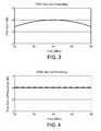
- FIG. 4is a plot of the frequency response of the power line directional coupler system in the forward transmission direction with pre-scaling of the subcarrier signals.
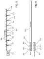
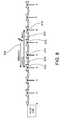
- FIGS. 5 , 7 A, 7 B, and 8are schematic diagrams of a transmission line with repeaters.
- FIG. 6is diagram showing the format of a data bearing packet and a no-load packet.
- a directional coupler 100includes a first transceiver 102 and a second transceiver 104 coupled to a transmission line 106 (e.g., a power line) through respective taps.
- the tap 108 (or “tap A”) for the first transceiver 102 and the tap 110 (or “tap B”) for the second transceiver 104are coupled to the transmission line 106 separated by a physical distance “d” along the power line of approximately 1 ⁇ 4 of a wavelength at the center of the frequency band used for modulating signals. Equivalently, this separation distance is the distance at which a sinusoidal signal propagating from one tap to the other undergoes a phase shift due to propagation of 90 degrees.
- the separationwould be approximately 1.25 meters, assuming a propagation velocity on the power line of 2 ⁇ 3 the speed of light in a vacuum.
- Other systemsmay operate over other frequency ranges (e.g., 2-28 MHz).
- the spacing of the two taps at a distance of approximately a quarter wavelength at the center frequency of the bandis used in some implementations because it enhances forward gain.
- other factorssuch as physical coupler size may dictate that the directional coupler is implemented with a tap spacing other than a quarter wavelength at center frequency.
- any of a variety of modulation schemesmay be implemented by the synchronized transceivers 102 and 104 , that convert data to and from a signal waveform that is transmitted over the transmission line 106 .
- One exemplary modulation schemeis OFDM.
- OFDMorthogonal frequency division multiple access
- Each symbolhas a predetermined time duration or symbol time T s .
- Each symbolincludes a Guard Interval (to combat the effects of multipath distortion) and a Fast Fourier Transform (FFT) evaluation period (T FFT ).
- OFDM symbolsare generated from a superposition of N sinusoidal waveforms that are orthogonal to each other over the period T FFT and form the OFDM subcarriers.
- Each subcarrierhas a peak frequency f i and a phase ⁇ i measured from the beginning of the symbol. For each of these mutually orthogonal subcarriers, a whole number of periods of the sinusoidal waveform is contained within the symbol time T FFT .
- the phases ⁇ i and amplitudes A i of the subcarrier waveformscan be independently selected (according to an appropriate modulation scheme) without affecting the orthogonality of the resulting modulated waveforms.
- the subcarriersoccupy a frequency range between frequencies f 1 and f N referred to as the OFDM bandwidth.
- a communication system 200includes a transmitter 202 for transmitting a signal (e.g., a sequence of OFDM symbols) over a communication medium 204 to a receiver 206 .
- the transmitter 202 and receiver 206can both be incorporated into a network interface module at each station.
- the communication medium 204can represent a path from one device to another over the transmission line 106 .
- modules implementing the physical (PHY) layerreceive a data unit from the medium access control (MAC) layer.
- the data unitis sent to an encoder module 220 to perform processing such as scrambling, error correction coding and interleaving.
- the encoded datais fed into a mapping module 222 that takes groups of data bits (e.g., 1, 2, 3, 4, 6, 8, or 10 bits), depending on the constellation used for the current symbol (e.g., a binary phase shift keyed (BPSK), quadrature phase shift keyed (QPSK), 8 point Quadrature Amplitude Modulated (8-QAM), 16-QAM, 64-QAM, 256-QAM, or 1024-QAM constellation), and maps the data value represented by those bits onto the corresponding amplitudes of in-phase (I) and quadrature-phase (Q) components of a subcarrier waveform of the current symbol.
- BPSKbinary phase shift keyed
- QPSKquadrature phase shift keyed
- 8-QAM8 point Quadrature Amplitude Modulated
- any appropriate modulation schemethat associates data values to modulated subcarrier waveforms can be used.
- PNPseudo Noise
- the mapping module 222also determines the type of modulation to be used on each of the subcarriers (or “tones”) according to a “tone map.”
- the tone mapcan be a default tone map, or a customized tone map determined by the receiving station, as described in more detail below.
- An inverse discrete Fourier transform (IDFT) module 224performs the modulation of the resulting set of N complex numbers (some of which may be zero for unused subcarriers) determined by the mapping module 222 onto N orthogonal subcarrier waveforms having peak frequencies f 1 , . . . , f N .
- the modulated subcarriersare combined by IDFT module 224 to form a discrete time symbol waveform S(n) (for a sampling rate f R ), which can be written as
- a post-processing module 226combines a sequence of consecutive (potentially overlapping) symbols into a “symbol set” that can be transmitted as a continuous block over the communication medium 204 .
- the post-processing module 226prepends a preamble to the symbol set that can be used for automatic gain control (AGC) and symbol timing synchronization.
- AGCautomatic gain control
- the post-processing module 226can extend each symbol with a cyclic prefix, or Guard Interval, that is a copy of the last part of the symbol.
- the post-processing module 226can also perform other functions such as applying a pulse shaping window to subsets of symbols within the symbol set (e.g., using a raised cosine window or other type of pulse shaping window) and overlapping the symbol subsets.
- An Analog Front End (AFE) module 228couples an analog signal containing a continuous-time (e.g., low-pass filtered) version of the symbol set to the communication medium 204 .
- the effect of the transmission of the continuous-time version of the waveform S(t) over the communication medium 204can be represented by convolution with a function g( ⁇ ;t) representing an impulse response of transmission over the communication medium.
- the communication medium 204may add noise n(t), which may be random noise and/or narrowband noise emitted by a jammer.
- modules implementing the PHY layerreceive a signal from the communication medium 204 and generate an data unit for the MAC layer.
- An AFE module 230operates in conjunction with an Automatic Gain Control (AGC) module 232 and a time synchronization module 234 to provide sampled signal data and timing information to a discrete Fourier transform (DFT) module 236 .
- AGCAutomatic Gain Control
- DFTdiscrete Fourier transform
- the receiver 206feeds the sampled discrete-time symbols into DFT module 236 to extract the sequence of N complex numbers representing the encoded data values (by performing an N-point DFT).
- Demodulator/Decoder module 238maps the complex numbers onto the corresponding bit sequences and performs the appropriate decoding of the bits (including deinterleaving and descrambling).
- the directional coupler 100uses a PHY layer modulation scheme, for example OFDM, with the added feature suppressing the signal transmitted or received in one direction of propagation on the transmission line 106 .
- the two transceivers 102 and 104are controlled by a common signal processing unit 112 .
- the signal processing unit 112enables the signals transmitted and received by the transceivers 102 and 104 to be processed using common signal references, such as a common clock reference, which can be used to define a common phase reference for setting relative phases between the subcarriers of the two transceivers.
- the signal processing unit 112generates baseband signal characteristics such as amplitudes and phases to be used for modulating respective subcarrier frequencies in a multi-carrier modulation scheme (e.g., OFDM as described in more detail above and in U.S. Publication No. 2006/0256881 A1 and U.S. Application No. 60/941,949, each of which is incorporated herein by reference).
- a multi-carrier modulation schemee.g., OFDM as described in more detail above and in U.S. Publication No. 2006/0256881 A1 and U.S. Application No. 60/941,949, each of which is incorporated herein by reference.
- an information bearing signal 122designated INFO
- a second signal 124designated CANCEL
- the purpose of the CANCEL signal 124is to null the INFO signal 122 in the undesired (REVERSE) direction. Because of the predetermined physical distance between the signal taps and the predetermined phase relationships between subcarriers emanating from the signal taps, as described in more detail below, the two signals combine constructively in the desired (FORWARD) direction—thus providing gain in the FORWARD direction. For the purpose of illustration, assume that there are no major signal impairments or impedance mismatches in either the FORWARD or REVERSE directions.
- the CANCEL signaluses the same subcarrier amplitudes as the INFO signal with a predetermined phase shift (or “rotation”) of each subcarrier of the OFDM signal such that the two signals nullify each other in the REVERSE direction.
- the exact phase rotation for each subcarrieris dependent on the distance, d, between the two signal taps, A 108 and B 110 , and the frequency of the subcarrier.
- the predetermined relative phase shift between subcarriers at tap A 108 and tap B 110are established explicitly or implicitly based on a common phase reference at tap A and tap B.
- the transceivers 102 and 104couple signals to and from the taps according to a common phase reference that is provided, for example, by the signal processing unit 112 , or established by some technique for establishing a common phase reference (e.g., using synchronized clocks as described in U.S. Publication No. 2007/0025398 A1, incorporated herein by reference).
- a common phase referencethat is provided, for example, by the signal processing unit 112 , or established by some technique for establishing a common phase reference (e.g., using synchronized clocks as described in U.S. Publication No. 2007/0025398 A1, incorporated herein by reference).
- dynamically controlled phase shifts between subcarriers generated at tap A and tap B, relative to this common phase referenceenable dynamically selectable cancellation in the REVERSE direction and constructive interference in the FOR
- An imposed relative phase shift ⁇ ( ⁇ ) of a subcarrier of wavelength ⁇ within the CANCEL signal 124 relative to the same subcarrier in the INFO signal 122can be determined as follows.
- a subcarrierhas a spectrum with a spectral shape that has a maximum value (or “peak”) at a “peak frequency” and tapers off away from the peak frequency.
- the subcarriershave a spectral shape that is approximately a sinc function.
- the wavelength or frequency of the subcarriercorresponds to the wavelength or frequency at a peak of the spectrum.
- the resulting combined signalwill be cancelled if the sum of the imposed relative phase ⁇ ( ⁇ ) and the acquired relative phase shift ⁇ ( ⁇ ) add to ⁇ (or 180 degrees).
- the amplitude of the subcarriers in the CANCEL signalare identical to those in the INFO signal.
- the INFO subcarrier signal 122(shown as the solid line) starts propagating from tap A 108 with a phase shift of ⁇ ( ⁇ ) relative to the same subcarrier in the CANCEL signal 124 .
- tap B 110When the INFO subcarrier signal reaches tap B 110 , it is combined with the CANCEL signal propagating from tap B (shown as the dashed line) according to a total phase that is the sum of the initial relative phase shift- ⁇ ( ⁇ ) and the acquired relative phase shift ⁇ ( ⁇ ), which adds to ⁇ ( ⁇ ) ⁇ ( ⁇ ).
- the INFO subcarrier signalis combined with the CANCEL subcarrier signal according to a total relative phase shift of zero, resulting in a doubling of the signal amplitude.
- the INFO and CANCEL subcarrier signalsare added with a nonzero relative phase 4 ⁇ d/ ⁇ , but still add constructively over a relatively large wavelength range.
- the designation of which transceiver provides the “INFO” signals and which provides the “CANCEL” signalsis arbitrary, such that the choice of direction in which signals are canceled and direction in which signals constructively add can be controlled dynamically depending on the desired destination of a signal.
- the directional coupler 100applies the appropriate relative phase shift by imposing a phase shift on either or both of the taps.
- the INFO and CANCEL signalscan each be applied to different taps such that the imposed phase shift ⁇ ( ⁇ ) is applied to the signal at tap A 108 instead of the signal at tap B 110 .
- the INFO and CANCEL signalscan be applied to the same taps with the sign of the imposed phase shift ⁇ ( ⁇ ) changed such that an imposed phase shift of ⁇ ( ⁇ ) is applied to the signal at tap B.
- the direction in which a signal is cancelledwill be called the REVERSE direction, but this direction may be dynamically controlled to be either direction on the transmission line (i.e., LEFT or RIGHT). It is also possible to linearly combine two different signals and transmit them simultaneously in different directions on the transmission line by arranging one signal to add in the LEFT direction and cancel in the RIGHT direction and the other signal to add in the RIGHT direction and cancel in the LEFT direction.
- the behavior of the directional coupler 100 for transmitting signalsalso describes the behavior of the directional coupler for receiving signals.
- the two signal taps A 108 and B 110can be thought of as a linear array.
- An array factor that represents a gain for coupling signals between the transmission line 106 and an array of tapsapplies to both transmission gain and reception gain.
- a null (or at least a partial null—e.g., reduction of 20 dB or 50 dB or more) in the array factorcan be provided in one direction on the transmission line while a useful signal level or even a gain greater than 0 dB or as high as 3 dB, for example, is provided in the other direction.
- phase shifts as calculated abovecan be used to process signals received at the two taps to recover signals from one direction while blocking signals from the other direction.
- the signals received at each tapare processed to impose the required phase shifts using a programmable phase rotator on each subcarrier and the two resulting signals may be added together prior to demodulation to suppress and substantially cancel signals that are propagating on the transmission line in one direction while passing or enhancing signals that are propagating the other direction on the transmission line. This enables the directional coupler to simultaneously receive two different signals from opposite directions on the transmission line.
- a single transceivercan provide signals to and receive signals from both taps.
- any number of tapse.g., three or four or more
- more than two tapsmay be used to increase the effective bandwidth over which gain is provided in one direction while nulling the other direction.
- FIG. 3is a plot of signal gain in the forward direction, measured in decibels, as a function of frequency for system that does not use amplitude prescaling.
- the center subcarrier at 40 MHzexperiences a forward gain of approximately 6 dB (3 dB of gain is due to the array factor and 3 dB is due to the fact that twice as much power is being injected into the system relative to a system using a single transceiver).
- Subcarriers at other frequencies closer to the edges of the signal bandwidthexperience reduced forward signal gain due to amplitude taper.
- This amplitude taperis generally undesirable because regulatory limits are imposed on transmitted power. If the signal at band center is held within regulatory limits, the signal at band edge will be further suppressed due to the aforementioned amplitude taper.
- the INFO signalmay be prescaled in amplitude to compensate for this amplitude taper across the signal bandwidth.
- amplitude prescalingis accomplished by inverting the gain curve in FIG. 3 and normalizing gain at band center to 0 dB.
- the prescaled signalis injected into the directional coupler, the result is an ideal flat gain across the entire signal bandwidth as shown in FIG. 4 .
- the ability to send a packet in one selectable directionhelps mitigate the hidden node problem, but it does not eliminate it.
- a head end transceiver 510Node 0
- a series of eight pole top repeaters 511 - 518Nodes 1 - 8 respectively. If Node 3 is sending a packet 522 to Node 4 by means of a directional coupler, Nodes 0 - 2 would be blind to the directional transmission. It would be possible for Node 2 to commence a transmission 524 to Node 4 while the transmission of a packet 522 from Node 3 is still in progress.
- This medium access protocol packetcontains Source, Destination, and Duration information of a directional transmission.
- the access protocol packetdoes not include a payload, and is therefore designated a “NOLOAD” packet for descriptive purposes.
- FIG. 6shows a NOLOAD packet 610 which does not have a payload, and a DATA packet 620 which does have a payload 628 .
- the DATA packet 620includes a header including a source field 622 , a destination field 624 , and a duration field 626 .
- the NOLOAD packetincludes a source field 612 , a destination field 614 , and a duration field 616 .
- the NOLOAD packet 610is sent in the REVERSE direction in order to notify stations that a directed transmission of the DATA packet 620 in the FORWARD direction is in progress. Packets that would otherwise result in a collision may be queued until the directed DATA packet transmission (from transmitting node to receiving node) and ensuing acknowledgement (ACK) packet transmission (from receiving node to transmitting node) are complete.
- NOLOAD-Aa NOLOAD packet 722 (“NOLOAD-A”) is sent at the start of transmission of the directed DATA packet 724 (“DATA-A”) as shown.
- DATA-Adirected DATA packet 724
- DATA-A 724is protected from potential interference from upstream sources, while upstream bandwidth may still be reused to the extent it does not overlap in space and direction of propagation with the reserved bandwidth.
- signalsmay be transmitted in the upstream direction by any station and any station outside the listening range of the destination node for DATA-A may also send transmissions in the downstream direction.
- An exemplary scenario for bandwidth reuseis described below.
- the source node 713senses that the medium is in the idle state. Later at time t 1 , the source node 713 commences transmission of DATA-A 724 to a downstream destination node 716 and transmits NOLOAD-A 722 to upstream nodes. At time t 2 , transmission of NOLOAD-A is completed. At time t 3 , the head end 710 begins transmission of a second data packet to another node 712 which is upstream from the destination node for DATA-A. The second data packet is able to be sent without interfering with the DATA-A reception because, in this scenario, the head end 710 is outside of the listening domain or range of the destination node 716 .
- the second destination node 712sends an ACK message back to the head end 710 .
- the first destination node 716sends an ACK message back to the first source node 713 . No collisions occur in the course of the preceding scenario.
- FIG. 7Bshows a second scenario in which multiple listening domains are present.
- a node suitably equipped with a directional coupleris able to simultaneously transmit in both directions or simultaneously receive in both directions.
- NOLOAD-Athe NOLOAD packet for one direction
- DATA-Bthe DATA packet
- This pairingmay be accomplished by adding optional fields representing NOLOAD-A to the header for DATA-B.
- the pairingmay be accomplished by appending NOLOAD-A packet to transmission for DATA-B before the delay for channel relinquishment under the CSMA-CA protocol has expired.
- An exemplary scenario for this form of bandwidth reuseis described below.
- a first source node 711commences transmission of DATA-A 722 in the downstream direction to destination node 714 .
- a second source node 718simultaneously commences transmission of DATA-B 724 in the upstream direction to the same destination node 714 .
- the destination nodesimultaneously commences transmission of ACK messages to both source nodes 711 and 718 in their respective directions.
- the destination node 714commences a forwarding transmission of DATA-A in the downstream direction to a secondary destination node 718 .
- the destination node 714simultaneously commences a forwarding transmission of DATA-B in the upstream direction to another secondary destination node 710 .
- the secondary destination nodes 710 and 718simultaneously transmit ACK messages back to the forwarding node 714 , which simultaneously receives the two ACK messages propagating in their respective directions on the medium. No collisions occur in the course of the preceding scenario.
- additional techniquescan be used to account for the fact that power lines are not necessarily ideal transmission lines for signals operating in the 2-80 MHz range. For example, it is possible to have large signal reflections due to impedance mismatches. If such a reflection occurs in the FORWARD direction of a directional transmission, the reflected signal could then propagate in the REVERSE direction. This may reduce the ability of the directional couplers at each node to provide signal nulling in the REVERSE direction.
- line conditionsare not static. Changes in temperature, weather, or load conditions can alter the propagation characteristics of a transmission line. Therefore, the use of fixed phase shifts based solely on subcarrier frequency and the tap spacing may not result in optimal signal cancellation in the REVERSE direction or maximize signal gain in the FORWARD direction.
- a data packet 822is transmitted downstream from source node 814 to a destination node 816 (FORWARD direction being left-to-right in this case).
- part of the signal 824is reflected back in the reverse direction by an impedance mismatch near another node 815 along the signal path.
- the composite signal in the REVERSE direction measured at an upstream node 813would consist of:
- the composite signal in the REVERSEis measured at the upstream node 813 , degradation in the signal null could be detected. If this information is further communicated to the source node 814 as feedback, adaptive measures could be taken to adjust the CANCEL signal 826 at the source node to restore the signal null in the reverse direction to it's original value. This may require manipulation of the CANCEL signal in both amplitude and phase. This may result in a trade-off between REVERSE direction nulling and FORWARD gain flatness. In general, deep signal nulls may require a very high degree of phase and amplitude control over the CANCEL signal. Relatively slight variations in local propagation conditions can have significant adverse impact on REVERSE signal null depths. In order to achieve consistently deep signal nulls in the REVERSE directions, the directional coupler can be configured to use adaptive methods for selecting the amplitudes and/or phases of the subcarriers.
- Feedback signalsmay be communicated from a measuring node to an adapting node, in the example above from measuring node 813 to adapting node 814 , by control signaling on the transmission line.
- This control signalingmay use the same frequency band as higher network layer data signals, for example by encoding feedback information in a logical subchannel of transmissions from 813 to 814.
- feedback informationmay be transmitted out of band in a dedicated frequency band or timeslot allocated to PHY layer control signaling.
Landscapes
- Engineering & Computer Science (AREA)
- Business, Economics & Management (AREA)
- Health & Medical Sciences (AREA)
- Economics (AREA)
- Power Engineering (AREA)
- Human Resources & Organizations (AREA)
- Water Supply & Treatment (AREA)
- General Health & Medical Sciences (AREA)
- Public Health (AREA)
- Marketing (AREA)
- Primary Health Care (AREA)
- Strategic Management (AREA)
- Tourism & Hospitality (AREA)
- Physics & Mathematics (AREA)
- General Business, Economics & Management (AREA)
- General Physics & Mathematics (AREA)
- Theoretical Computer Science (AREA)
- Cable Transmission Systems, Equalization Of Radio And Reduction Of Echo (AREA)
Abstract
Description
where the time index n goes from 1 to N. Ai is the amplitude and Φiis the phase of the subcarrier with peak frequency fi=(i/N)fR, and j=√
Φ(λ)=2πd/λ Eq. (2)
where λ is the wavelength of the subcarrier on the
β(λ)=π−Φ(λ) Eq. (3)
In this case, the amplitude of the subcarriers in the CANCEL signal are identical to those in the INFO signal.
Claims (70)
Priority Applications (1)
| Application Number | Priority Date | Filing Date | Title |
|---|---|---|---|
| US12/421,543US8571118B2 (en) | 2008-04-09 | 2009-04-09 | Transmission line directional coupling |
Applications Claiming Priority (2)
| Application Number | Priority Date | Filing Date | Title |
|---|---|---|---|
| US4358108P | 2008-04-09 | 2008-04-09 | |
| US12/421,543US8571118B2 (en) | 2008-04-09 | 2009-04-09 | Transmission line directional coupling |
Publications (2)
| Publication Number | Publication Date |
|---|---|
| US20090290650A1 US20090290650A1 (en) | 2009-11-26 |
| US8571118B2true US8571118B2 (en) | 2013-10-29 |
Family
ID=41162613
Family Applications (3)
| Application Number | Title | Priority Date | Filing Date |
|---|---|---|---|
| US12/421,543Expired - Fee RelatedUS8571118B2 (en) | 2008-04-09 | 2009-04-09 | Transmission line directional coupling |
| US12/421,452Expired - Fee RelatedUS8368349B2 (en) | 2008-04-09 | 2009-04-09 | Transmission line directional awareness for a charging station |
| US13/712,876Expired - Fee RelatedUS8860369B2 (en) | 2008-04-09 | 2012-12-12 | Phase control based on transmission line directional awareness |
Family Applications After (2)
| Application Number | Title | Priority Date | Filing Date |
|---|---|---|---|
| US12/421,452Expired - Fee RelatedUS8368349B2 (en) | 2008-04-09 | 2009-04-09 | Transmission line directional awareness for a charging station |
| US13/712,876Expired - Fee RelatedUS8860369B2 (en) | 2008-04-09 | 2012-12-12 | Phase control based on transmission line directional awareness |
Country Status (3)
| Country | Link |
|---|---|
| US (3) | US8571118B2 (en) |
| EP (1) | EP2281333A2 (en) |
| WO (1) | WO2009126811A2 (en) |
Cited By (2)
| Publication number | Priority date | Publication date | Assignee | Title |
|---|---|---|---|---|
| US20110255557A1 (en)* | 2010-04-20 | 2011-10-20 | Texas Instruments Incorporated | Coexistence of Prime, S-FSK and G3 Devices in Powerline Communications |
| US20230117407A1 (en)* | 2021-10-19 | 2023-04-20 | Chargepoint, Inc. | Dynamic allocation of power modules for charging electric vehicles |
Families Citing this family (69)
| Publication number | Priority date | Publication date | Assignee | Title |
|---|---|---|---|---|
| US8368351B2 (en)* | 2008-04-09 | 2013-02-05 | Qualcomm Incorporated | Transmission line directional awareness for a charging station |
| US8571118B2 (en)* | 2008-04-09 | 2013-10-29 | Qualcomm Incorporated | Transmission line directional coupling |
| US8564403B2 (en)* | 2009-03-18 | 2013-10-22 | Mario Landau-Holdsworth | Method, system, and apparatus for distributing electricity to electric vehicles, monitoring the distribution thereof, and/or controlling the distribution thereof |
| US8013570B2 (en) | 2009-07-23 | 2011-09-06 | Coulomb Technologies, Inc. | Electrical circuit sharing for electric vehicle charging stations |
| US9878629B2 (en) | 2009-12-17 | 2018-01-30 | Chargepoint, Inc. | Method and apparatus for electric vehicle charging station load management in a residence |
| AT509314B1 (en)* | 2009-12-23 | 2016-01-15 | Mehler Elektrotechnik Ges M B H | DEVICE FOR TENNING A CHARGING ELECTRIC BATTERY FOR AN ELECTRIC VEHICLE |
| US20120319650A1 (en)* | 2010-03-29 | 2012-12-20 | Toshiya Iwasaki | Recharging system |
| US8340833B2 (en) | 2010-03-31 | 2012-12-25 | General Electric Company | Control distribution transformer and method of making same |
| US9263182B2 (en) | 2010-03-31 | 2016-02-16 | General Electric Company | Control distribution transformer and method of making same |
| US8102148B2 (en) | 2010-03-31 | 2012-01-24 | General Electric Company | Augmented distribution transformer and method of making same |
| US8324860B2 (en)* | 2010-04-06 | 2012-12-04 | Evp Technology Llc Usa | Distributed charging system and method for electrical vehicle |
| DE102010021866B4 (en) | 2010-05-28 | 2021-09-30 | Sew-Eurodrive Gmbh & Co Kg | Device for contactless energy transmission and method of operation |
| US8841881B2 (en) | 2010-06-02 | 2014-09-23 | Bryan Marc Failing | Energy transfer with vehicles |
| DE102010026689A1 (en)* | 2010-07-09 | 2012-01-12 | Siemens Aktiengesellschaft | Method and control unit for charging a vehicle battery |
| US20120074901A1 (en)* | 2010-09-27 | 2012-03-29 | Tim Mohammed | Centralized charging station |
| US9026813B2 (en) | 2010-11-22 | 2015-05-05 | Qualcomm Incorporated | Establishing a power charging association on a powerline network |
| US8896265B2 (en)* | 2011-01-31 | 2014-11-25 | Toyota Motor Engineering & Manufacturing North America, Inc. | Charge transfer devices for plug-in electric vehicles |
| US9003492B2 (en) | 2011-06-21 | 2015-04-07 | Qualcomm Incorporated | Secure client authentication and service authorization in a shared communication network |
| TWI486909B (en) | 2011-07-26 | 2015-06-01 | 睿能創意公司 | Apparatus, method and article for providing vehicle diagnostic data |
| JP6026535B2 (en) | 2011-07-26 | 2016-11-16 | ゴゴロ インク | RESERVED POWER STORAGE DEVICE DEVICE, METHOD, AND ARTICLE FOR RESERVING A POWER STORAGE DEVICE IN A COLLECTION, CHARGING AND DISTRIBUTION MACHINE |
| WO2013016570A1 (en) | 2011-07-26 | 2013-01-31 | Gogoro, Inc. | Apparatus, method and article for authentication, security and control of power storage devices, such as batteries, based on user profiles |
| JP6422119B2 (en)* | 2011-07-26 | 2018-11-14 | ゴゴロ インク | Apparatus, method and article for redistributing a power storage device such as a battery between collection charge distribution devices |
| TWI584976B (en) | 2011-07-26 | 2017-06-01 | 睿能創意公司 | Dynamically limiting vehicle operation for best effort economy |
| ES2748199T3 (en) | 2011-07-26 | 2020-03-13 | Gogoro Inc | Apparatus, method and article for providing information on the availability of energy storage devices in an energy storage device collection, charging and dispensing machine |
| CN103891089B (en) | 2011-07-26 | 2016-10-12 | 睿能创意公司 | Apparatus, method and article for authentication, security and control of electric power storage devices such as batteries |
| US10186094B2 (en) | 2011-07-26 | 2019-01-22 | Gogoro Inc. | Apparatus, method and article for providing locations of power storage device collection, charging and distribution machines |
| US9424697B2 (en) | 2011-07-26 | 2016-08-23 | Gogoro Inc. | Apparatus, method and article for a power storage device compartment |
| US9021278B2 (en) | 2011-08-10 | 2015-04-28 | Qualcomm Incorporated | Network association of communication devices based on attenuation information |
| US8358102B2 (en)* | 2011-10-21 | 2013-01-22 | General Electric Company | System, charging device, and method of charging a power storage device |
| DE102012210262A1 (en)* | 2011-11-18 | 2013-05-23 | Robert Bosch Gmbh | Battery with a battery cell with external and integrated temperature sensor and method of operation of the battery |
| US9620970B2 (en)* | 2011-11-30 | 2017-04-11 | The Regents Of The University Of California | Network based management for multiplexed electric vehicle charging |
| JP5899994B2 (en)* | 2012-02-10 | 2016-04-06 | ソニー株式会社 | Power feeding device, power receiving device, and program |
| JP6094047B2 (en) | 2012-02-13 | 2017-03-15 | ソニー株式会社 | Power feeding device, power receiving device, billing method, and program |
| JP5924050B2 (en) | 2012-03-16 | 2016-05-25 | ソニー株式会社 | Power feeding device, power receiving device, power feeding method, power receiving method, and program |
| TWI535168B (en)* | 2012-05-17 | 2016-05-21 | 台達電子工業股份有限公司 | Charging system |
| US9302594B2 (en)* | 2012-07-31 | 2016-04-05 | Qualcomm Incorporated | Selective communication based on distance from a plurality of electric vehicle wireless charging stations in a facility |
| US9403441B2 (en)* | 2012-08-21 | 2016-08-02 | Cooper Technologies Company | Autonomous management of distribution transformer power load |
| US11843260B2 (en) | 2012-11-09 | 2023-12-12 | California Institute Of Technology | Generator unit for wireless power transfer |
| US11616520B2 (en) | 2012-11-09 | 2023-03-28 | California Institute Of Technology | RF receiver |
| CN104885333B (en)* | 2012-11-09 | 2018-05-15 | 加州理工学院 | Smart RF Lensing: Efficient, Dynamic, and Mobile Wireless Power Transfer |
| EP2920027B1 (en) | 2012-11-16 | 2021-10-13 | Gogoro Inc. | System and method for vehicle turn signals |
| US11075530B2 (en) | 2013-03-15 | 2021-07-27 | Gogoro Inc. | Modular system for collection and distribution of electric storage devices |
| CN105745816B (en) | 2013-11-22 | 2018-10-16 | 加州理工学院 | Active C MOS recovery units for wireless power transmission |
| EP3072214B1 (en)* | 2013-11-22 | 2018-10-10 | California Institute of Technology | Generator unit for wireless power transfer |
| CN106605338B (en) | 2014-08-11 | 2019-07-16 | 睿能创意公司 | Multidirectional electric connector, plug and system |
| EP3183797B1 (en) | 2014-08-19 | 2020-10-07 | California Institute of Technology | Wireless power transfer |
| CN110481360B (en) | 2014-09-04 | 2023-06-16 | 睿能创意公司 | Charging module of portable electric energy storage device |
| US9573478B2 (en)* | 2014-11-14 | 2017-02-21 | Schneider Electric USA, Inc. | EVSE doubler add-on unit |
| US9804034B2 (en) | 2014-11-14 | 2017-10-31 | Schneider Electric USA, Inc. | EVSE with cordset handle temperature measurement |
| US9707850B2 (en) | 2014-11-18 | 2017-07-18 | Schneider Electric USA, Inc. | EVSE handle with automatic thermal shut down by NTC to ground |
| CN104377785B (en)* | 2014-12-03 | 2017-06-27 | 郑伟雄 | A kind of electric motorcar charging station and application method |
| CN104578325B (en)* | 2015-02-05 | 2016-10-05 | 郑伟雄 | A kind of charging system of electric powercar and using method |
| DE102015210325A1 (en)* | 2015-06-03 | 2016-12-08 | Bayerische Motoren Werke Aktiengesellschaft | Method and system for monitoring charging stations |
| CN107873006B (en) | 2015-06-05 | 2021-02-02 | 睿能创意公司 | Vehicle and method for determining a specific type of load of an electric vehicle |
| KR101816977B1 (en)* | 2015-12-08 | 2018-01-09 | 현대자동차주식회사 | Method and apparatus for discovering a primary device of electric vehicle supply equipment and operating method of supply equipment communication controller |
| US11171509B2 (en)* | 2016-02-25 | 2021-11-09 | California Institute Of Technology | Adaptive charging network using adaptive charging stations for electric vehicles |
| US10150380B2 (en) | 2016-03-23 | 2018-12-11 | Chargepoint, Inc. | Dynamic allocation of power modules for charging electric vehicles |
| CN105762906B (en)* | 2016-05-10 | 2018-02-27 | 国网辽宁省电力有限公司检修分公司 | A kind of valve Room operation platform cart intelligent charger and method |
| CN105867275B (en)* | 2016-05-13 | 2019-01-29 | 张慧 | A kind of automatic control system of charging pile power connection part |
| US10744883B2 (en) | 2016-05-25 | 2020-08-18 | Chargepoint, Inc. | Dynamic allocation of power modules for charging electric vehicles |
| WO2018218252A1 (en) | 2017-05-26 | 2018-11-29 | California Institute Of Technology | Method and apparatus for dynamic rf lens focusing and tracking of wireless power recovery unit |
| US10382094B2 (en)* | 2017-11-28 | 2019-08-13 | International Business Machines Corporation | Cable tracking by electromagnetic emission |
| WO2019109084A1 (en) | 2017-12-01 | 2019-06-06 | California Institute Of Technology | Optimization framework and methods for adaptive ev charging |
| CN108306358A (en)* | 2017-12-29 | 2018-07-20 | 国网北京市电力公司 | Charging station battery energy storage configuration method and device |
| CN108494034B (en)* | 2018-03-21 | 2021-11-02 | 电子科技大学 | A calculation method for electric vehicle charging load distribution in distribution network |
| US11218981B2 (en)* | 2018-09-20 | 2022-01-04 | Kabushiki Kaisha Toshiba | Wireless mesh network and data transmission method |
| KR102575725B1 (en)* | 2018-11-16 | 2023-09-07 | 현대자동차주식회사 | Apparatus, system and method for controlling charging of electric vehicle |
| WO2020163873A1 (en) | 2019-02-08 | 2020-08-13 | California Institute Of Technology | Systems and methods for adaptive ev charging |
| CN113067355B (en)* | 2021-03-30 | 2021-11-30 | 四川大学 | Electric automobile flexibility mining and cooperative regulation and control method for improving reliability of power grid |
Citations (27)
| Publication number | Priority date | Publication date | Assignee | Title |
|---|---|---|---|---|
| US2931901A (en) | 1954-12-01 | 1960-04-05 | Honeywell Regulator Co | Nonlinear control apparatus |
| US4084133A (en) | 1976-02-06 | 1978-04-11 | Hasler Ag | Method of and apparatus for determining the direction of the mutual temporal shift of at least two similar stochastic signals |
| US4864589A (en) | 1985-07-24 | 1989-09-05 | Nec Home Electronics Ltd. | Spread spectrum power line communications |
| US4876549A (en) | 1988-03-07 | 1989-10-24 | E-Systems, Inc. | Discrete fourier transform direction finding apparatus |
| US5398542A (en) | 1992-10-16 | 1995-03-21 | Nkk Corporation | Method for determining direction of travel of a wave front and apparatus therefor |
| US5497142A (en) | 1991-10-17 | 1996-03-05 | Electricite De France | Directional separator-coupler circuit for medium-frequency carrier currents on a low-voltage electrical line |
| US5724047A (en) | 1996-11-27 | 1998-03-03 | Hughes Electronics | Phase and time-difference precision direction finding system |
| US6281841B1 (en) | 1996-09-23 | 2001-08-28 | Techno International Limited | Direction determining apparatus |
| US6300881B1 (en) | 1999-06-09 | 2001-10-09 | Motorola, Inc. | Data transfer system and method for communicating utility consumption data over power line carriers |
| US6313795B1 (en) | 1997-10-10 | 2001-11-06 | Daimler-Benz Aerospace Ag | Direction-finding method for determining the incident direction of a high-frequency electromagnetic signal |
| US20030039317A1 (en) | 2001-08-21 | 2003-02-27 | Taylor Douglas Hamilton | Method and apparatus for constructing a sub-carrier map |
| US20030169155A1 (en) | 2000-04-14 | 2003-09-11 | Mollenkopf James Douglas | Power line communication system and method of using the same |
| US20040227622A1 (en) | 2003-05-13 | 2004-11-18 | Giannini Paul M. | Device and method for communicating data signals through multiple power line conductors |
| WO2006012681A1 (en) | 2004-08-02 | 2006-02-09 | Donald Malcolm Ross Yelland | Method and device for power line head-end data transmission |
| US20060087346A1 (en) | 2004-10-22 | 2006-04-27 | Advantest Corporation | Phase difference detecting apparatus |
| WO2006047270A2 (en) | 2004-10-26 | 2006-05-04 | Current Technologies, Llc | Power line communications system and method |
| WO2006118850A2 (en) | 2005-04-29 | 2006-11-09 | Current Technologies, Llc | Power line coupling device and method of use |
| US20060259254A1 (en) | 2000-02-29 | 2006-11-16 | Swarztrauber Sayre A | System and method for on-line monitoring and billing of power consumption |
| US20070135085A1 (en) | 2005-12-09 | 2007-06-14 | Ryuichi Iwamura | System and method for providing access in powerline communications (PLC) network |
| US20080040296A1 (en) | 2006-08-10 | 2008-02-14 | V2 Green Inc. | Electric Resource Power Meter in a Power Aggregation System for Distributed Electric Resources |
| US20080096500A1 (en)* | 2002-12-20 | 2008-04-24 | Texas Instruments Incorporated | Method for Calibrating Automatic Gain Control in Wireless Devices |
| US7414962B2 (en) | 2000-04-18 | 2008-08-19 | Sony Deutschland Gmbh | OFDM diversity transmission |
| US20090212762A1 (en) | 2005-09-09 | 2009-08-27 | Nxp B.V. | Phase detector system |
| US20090228223A1 (en) | 2008-03-04 | 2009-09-10 | Zhenning Liu | Power line communication based aircraft power distribution system with real time wiring integrity monitoring capability |
| US20090261779A1 (en) | 2008-04-09 | 2009-10-22 | Intellon Corporation | Transmission line directional awareness |
| US7701325B2 (en) | 2002-12-10 | 2010-04-20 | Current Technologies, Llc | Power line communication apparatus and method of using the same |
| US20100274697A1 (en) | 2008-04-09 | 2010-10-28 | Atheros Communications, Inc. | Transmission line directional awareness |
- 2009
- 2009-04-09USUS12/421,543patent/US8571118B2/ennot_activeExpired - Fee Related
- 2009-04-09WOPCT/US2009/040078patent/WO2009126811A2/enactiveApplication Filing
- 2009-04-09EPEP09730645Apatent/EP2281333A2/ennot_activeWithdrawn
- 2009-04-09USUS12/421,452patent/US8368349B2/ennot_activeExpired - Fee Related
- 2012
- 2012-12-12USUS13/712,876patent/US8860369B2/ennot_activeExpired - Fee Related
Patent Citations (31)
| Publication number | Priority date | Publication date | Assignee | Title |
|---|---|---|---|---|
| US2931901A (en) | 1954-12-01 | 1960-04-05 | Honeywell Regulator Co | Nonlinear control apparatus |
| US4084133A (en) | 1976-02-06 | 1978-04-11 | Hasler Ag | Method of and apparatus for determining the direction of the mutual temporal shift of at least two similar stochastic signals |
| US4864589A (en) | 1985-07-24 | 1989-09-05 | Nec Home Electronics Ltd. | Spread spectrum power line communications |
| US4876549A (en) | 1988-03-07 | 1989-10-24 | E-Systems, Inc. | Discrete fourier transform direction finding apparatus |
| US5497142A (en) | 1991-10-17 | 1996-03-05 | Electricite De France | Directional separator-coupler circuit for medium-frequency carrier currents on a low-voltage electrical line |
| US5398542A (en) | 1992-10-16 | 1995-03-21 | Nkk Corporation | Method for determining direction of travel of a wave front and apparatus therefor |
| US6281841B1 (en) | 1996-09-23 | 2001-08-28 | Techno International Limited | Direction determining apparatus |
| US5724047A (en) | 1996-11-27 | 1998-03-03 | Hughes Electronics | Phase and time-difference precision direction finding system |
| US6313795B1 (en) | 1997-10-10 | 2001-11-06 | Daimler-Benz Aerospace Ag | Direction-finding method for determining the incident direction of a high-frequency electromagnetic signal |
| US6300881B1 (en) | 1999-06-09 | 2001-10-09 | Motorola, Inc. | Data transfer system and method for communicating utility consumption data over power line carriers |
| US20060259254A1 (en) | 2000-02-29 | 2006-11-16 | Swarztrauber Sayre A | System and method for on-line monitoring and billing of power consumption |
| US20030169155A1 (en) | 2000-04-14 | 2003-09-11 | Mollenkopf James Douglas | Power line communication system and method of using the same |
| US7414962B2 (en) | 2000-04-18 | 2008-08-19 | Sony Deutschland Gmbh | OFDM diversity transmission |
| US20030039317A1 (en) | 2001-08-21 | 2003-02-27 | Taylor Douglas Hamilton | Method and apparatus for constructing a sub-carrier map |
| US7701325B2 (en) | 2002-12-10 | 2010-04-20 | Current Technologies, Llc | Power line communication apparatus and method of using the same |
| US20080096500A1 (en)* | 2002-12-20 | 2008-04-24 | Texas Instruments Incorporated | Method for Calibrating Automatic Gain Control in Wireless Devices |
| US20040227622A1 (en) | 2003-05-13 | 2004-11-18 | Giannini Paul M. | Device and method for communicating data signals through multiple power line conductors |
| WO2006012681A1 (en) | 2004-08-02 | 2006-02-09 | Donald Malcolm Ross Yelland | Method and device for power line head-end data transmission |
| US20060087346A1 (en) | 2004-10-22 | 2006-04-27 | Advantest Corporation | Phase difference detecting apparatus |
| WO2006047270A2 (en) | 2004-10-26 | 2006-05-04 | Current Technologies, Llc | Power line communications system and method |
| US7307512B2 (en) | 2005-04-29 | 2007-12-11 | Current Technologies, Llc | Power line coupling device and method of use |
| WO2006118850A2 (en) | 2005-04-29 | 2006-11-09 | Current Technologies, Llc | Power line coupling device and method of use |
| US20090212762A1 (en) | 2005-09-09 | 2009-08-27 | Nxp B.V. | Phase detector system |
| US20070135085A1 (en) | 2005-12-09 | 2007-06-14 | Ryuichi Iwamura | System and method for providing access in powerline communications (PLC) network |
| US20080040296A1 (en) | 2006-08-10 | 2008-02-14 | V2 Green Inc. | Electric Resource Power Meter in a Power Aggregation System for Distributed Electric Resources |
| US20090228223A1 (en) | 2008-03-04 | 2009-09-10 | Zhenning Liu | Power line communication based aircraft power distribution system with real time wiring integrity monitoring capability |
| US20090261779A1 (en) | 2008-04-09 | 2009-10-22 | Intellon Corporation | Transmission line directional awareness |
| US20100274697A1 (en) | 2008-04-09 | 2010-10-28 | Atheros Communications, Inc. | Transmission line directional awareness |
| US8368349B2 (en) | 2008-04-09 | 2013-02-05 | Qualcomm Incorporated | Transmission line directional awareness for a charging station |
| US8368351B2 (en) | 2008-04-09 | 2013-02-05 | Qualcomm Incorporated | Transmission line directional awareness for a charging station |
| US20130099743A1 (en) | 2008-04-09 | 2013-04-25 | Qualcomm Incorporated | Transmission line directional awareness |
Non-Patent Citations (6)
| Title |
|---|
| "HomePlug AV White Paper", 2005, 11 Pages.* |
| "U.S. Appl. No. 12/421,452 Office Action", 18 pages, Apr. 9, 2009. |
| "U.S. Appl. No. 13/712,876 Office Action", Aug. 15, 2013, 14 pages. |
| Co-pending U.S. Appl. No. 13/712,876, filed Dec. 12, 2012, 32 pages. |
| International Search Report and Written Opinion in PCT Application No. PCT/US2009/040078, dated Jun. 5, 2009, 12 pages. |
| International Search Report and Written Opinion in PCT Application No. PCT/US2010/039615, dated Aug. 19, 2010, 12 pages. |
Cited By (3)
| Publication number | Priority date | Publication date | Assignee | Title |
|---|---|---|---|---|
| US20110255557A1 (en)* | 2010-04-20 | 2011-10-20 | Texas Instruments Incorporated | Coexistence of Prime, S-FSK and G3 Devices in Powerline Communications |
| US8743908B2 (en)* | 2010-04-20 | 2014-06-03 | Texas Instruments Incorporated | Coexistence of prime, S-FSK and G3 devices in powerline communications |
| US20230117407A1 (en)* | 2021-10-19 | 2023-04-20 | Chargepoint, Inc. | Dynamic allocation of power modules for charging electric vehicles |
Also Published As
| Publication number | Publication date |
|---|---|
| US8860369B2 (en) | 2014-10-14 |
| EP2281333A2 (en) | 2011-02-09 |
| WO2009126811A3 (en) | 2009-12-30 |
| US8368349B2 (en) | 2013-02-05 |
| WO2009126811A2 (en) | 2009-10-15 |
| US20130099743A1 (en) | 2013-04-25 |
| US20090261779A1 (en) | 2009-10-22 |
| US20090290650A1 (en) | 2009-11-26 |
Similar Documents
| Publication | Publication Date | Title |
|---|---|---|
| US8571118B2 (en) | Transmission line directional coupling | |
| Yonge et al. | An overview of the HomePlug AV2 technology | |
| AU2009201967B2 (en) | Improved pilot allocation in multi-carrier systems with frequency notching | |
| US9374204B2 (en) | Transmission method and apparatus for cancelling inter-carrier interference | |
| US7961805B2 (en) | Method for the coding of an OFDM/OQAM signal using symbols with complex values, and corresponding signal, devices and computer programs | |
| US7904021B2 (en) | Selecting carriers for modulating signals in a communication network | |
| JP2000509578A (en) | Radio frequency interference mitigation in multicarrier transmission systems | |
| WO2005101774A1 (en) | Communication apparatus and communication method for a digital wavelet multicarrier transmission system | |
| Kiviranta et al. | Constant envelope multicarrier modulation: performance evaluation AWGN and fading channels | |
| JP4128867B2 (en) | Partial response signaling for orthogonal frequency division multiplexing | |
| Zhang et al. | FFT-based OFDM in broadband-PLC and narrowband-PLC | |
| US20040109497A1 (en) | Communications system including a narrow band demodulator | |
| US20030137405A1 (en) | Communication scheme suppressing leakage electromagnetic fields | |
| US7792211B2 (en) | System, modem, receiver, transmitter and method for improving transmission performance | |
| Wen et al. | Effective intercarrier interference reduction techniques for OFDM underwater acoustic communications | |
| JP2004173153A (en) | Transmitter and transversal filter | |
| US20040096021A1 (en) | Communications methods for narrow band demodulation | |
| Amasa | Inter Carrier Interference Cancellation in OFDM Systems | |
| CN101594334A (en) | Improved Pilot Allocation in Multicarrier Systems with Frequency Notching | |
| Yonge et al. | HomePlug AV2: Next-generation broadband over power line | |
| JP5796888B2 (en) | Receiving apparatus and receiving method using optical orthogonal frequency division multiplexing transmission system | |
| EP2129036B1 (en) | Improved pilot allocation in multi-carrier systems with frequency notching | |
| US20040096010A1 (en) | Communications system including a narrow band modulator | |
| US20140003477A1 (en) | Interleaved signaling | |
| Dostert et al. | Digital transmission techniques |
Legal Events
| Date | Code | Title | Description |
|---|---|---|---|
| AS | Assignment | Owner name:INTELLON CORPORATION, FLORIDA Free format text:ASSIGNMENT OF ASSIGNORS INTEREST;ASSIGNOR:ZYREN, JAMES;REEL/FRAME:022543/0665 Effective date:20090409 | |
| AS | Assignment | Owner name:ATHEROS POWERLINE LLC,CALIFORNIA Free format text:MERGER;ASSIGNOR:INTELLON CORPORAITON;REEL/FRAME:024103/0834 Effective date:20091215 Owner name:ATHEROS COMMUNICATIONS, INC.,CALIFORNIA Free format text:ASSIGNMENT OF ASSIGNORS INTEREST;ASSIGNOR:ATHEROS POWERLINE LLC;REEL/FRAME:024103/0872 Effective date:20091215 Owner name:ATHEROS POWERLINE LLC,CALIFORNIA Free format text:MERGER;ASSIGNOR:INTELLON CORPORATION;REEL/FRAME:024103/0834 Effective date:20091215 Owner name:ATHEROS POWERLINE LLC, CALIFORNIA Free format text:MERGER;ASSIGNOR:INTELLON CORPORATION;REEL/FRAME:024103/0834 Effective date:20091215 Owner name:ATHEROS COMMUNICATIONS, INC., CALIFORNIA Free format text:ASSIGNMENT OF ASSIGNORS INTEREST;ASSIGNOR:ATHEROS POWERLINE LLC;REEL/FRAME:024103/0872 Effective date:20091215 | |
| AS | Assignment | Owner name:QUALCOMM ATHEROS, INC., CALIFORNIA Free format text:MERGER;ASSIGNOR:ATHEROS COMMUNICATIONS, INC.;REEL/FRAME:026596/0214 Effective date:20110524 | |
| AS | Assignment | Owner name:QUALCOMM INCORPORATED, CALIFORNIA Free format text:ASSIGNMENT OF ASSIGNORS INTEREST;ASSIGNOR:QUALCOMM ATHEROS, INC.;REEL/FRAME:029394/0660 Effective date:20121022 | |
| FEPP | Fee payment procedure | Free format text:PAYER NUMBER DE-ASSIGNED (ORIGINAL EVENT CODE: RMPN); ENTITY STATUS OF PATENT OWNER: LARGE ENTITY Free format text:PAYOR NUMBER ASSIGNED (ORIGINAL EVENT CODE: ASPN); ENTITY STATUS OF PATENT OWNER: LARGE ENTITY | |
| STCF | Information on status: patent grant | Free format text:PATENTED CASE | |
| FPAY | Fee payment | Year of fee payment:4 | |
| FEPP | Fee payment procedure | Free format text:MAINTENANCE FEE REMINDER MAILED (ORIGINAL EVENT CODE: REM.); ENTITY STATUS OF PATENT OWNER: LARGE ENTITY | |
| LAPS | Lapse for failure to pay maintenance fees | Free format text:PATENT EXPIRED FOR FAILURE TO PAY MAINTENANCE FEES (ORIGINAL EVENT CODE: EXP.); ENTITY STATUS OF PATENT OWNER: LARGE ENTITY | |
| STCH | Information on status: patent discontinuation | Free format text:PATENT EXPIRED DUE TO NONPAYMENT OF MAINTENANCE FEES UNDER 37 CFR 1.362 | |
| FP | Lapsed due to failure to pay maintenance fee | Effective date:20211029 |