US8571014B2 - Distributed packet-based timestamp engine - Google Patents
Distributed packet-based timestamp engineDownload PDFInfo
- Publication number
- US8571014B2 US8571014B2US13/039,199US201113039199AUS8571014B2US 8571014 B2US8571014 B2US 8571014B2US 201113039199 AUS201113039199 AUS 201113039199AUS 8571014 B2US8571014 B2US 8571014B2
- Authority
- US
- United States
- Prior art keywords
- packets
- packet
- transmit
- timestamp
- time
- Prior art date
- Legal status (The legal status is an assumption and is not a legal conclusion. Google has not performed a legal analysis and makes no representation as to the accuracy of the status listed.)
- Active
Links
- 238000012545processingMethods0.000claimsabstractdescription33
- 238000004891communicationMethods0.000claimsdescription99
- 238000000034methodMethods0.000claimsdescription81
- 230000008569processEffects0.000claimsdescription65
- 238000001514detection methodMethods0.000claimsdescription6
- 239000004744fabricSubstances0.000claimsdescription4
- 230000005540biological transmissionEffects0.000description22
- 238000005259measurementMethods0.000description17
- 238000010586diagramMethods0.000description8
- 230000001934delayEffects0.000description7
- 230000001360synchronised effectEffects0.000description5
- 230000009471actionEffects0.000description4
- 239000000835fiberSubstances0.000description4
- 239000000872bufferSubstances0.000description3
- 230000001960triggered effectEffects0.000description2
- 230000009286beneficial effectEffects0.000description1
- 230000008901benefitEffects0.000description1
- 230000002457bidirectional effectEffects0.000description1
- 238000012937correctionMethods0.000description1
- 230000008878couplingEffects0.000description1
- 238000010168coupling processMethods0.000description1
- 238000005859coupling reactionMethods0.000description1
- 230000001186cumulative effectEffects0.000description1
- 230000001627detrimental effectEffects0.000description1
- 230000006870functionEffects0.000description1
- 230000002452interceptive effectEffects0.000description1
- 238000012986modificationMethods0.000description1
- 230000004048modificationEffects0.000description1
- 238000011084recoveryMethods0.000description1
- 238000012552reviewMethods0.000description1
- 230000011664signalingEffects0.000description1
- 238000012360testing methodMethods0.000description1
- 230000007704transitionEffects0.000description1
Images


Classifications
- H—ELECTRICITY
- H04—ELECTRIC COMMUNICATION TECHNIQUE
- H04L—TRANSMISSION OF DIGITAL INFORMATION, e.g. TELEGRAPHIC COMMUNICATION
- H04L43/00—Arrangements for monitoring or testing data switching networks
- H04L43/10—Active monitoring, e.g. heartbeat, ping or trace-route
- H04L43/106—Active monitoring, e.g. heartbeat, ping or trace-route using time related information in packets, e.g. by adding timestamps
- H—ELECTRICITY
- H04—ELECTRIC COMMUNICATION TECHNIQUE
- H04J—MULTIPLEX COMMUNICATION
- H04J3/00—Time-division multiplex systems
- H04J3/02—Details
- H04J3/06—Synchronising arrangements
- H04J3/0635—Clock or time synchronisation in a network
- H04J3/0685—Clock or time synchronisation in a node; Intranode synchronisation
- H04J3/0697—Synchronisation in a packet node
- H—ELECTRICITY
- H04—ELECTRIC COMMUNICATION TECHNIQUE
- H04L—TRANSMISSION OF DIGITAL INFORMATION, e.g. TELEGRAPHIC COMMUNICATION
- H04L43/00—Arrangements for monitoring or testing data switching networks
- H04L43/08—Monitoring or testing based on specific metrics, e.g. QoS, energy consumption or environmental parameters
- H04L43/0852—Delays
- H—ELECTRICITY
- H04—ELECTRIC COMMUNICATION TECHNIQUE
- H04L—TRANSMISSION OF DIGITAL INFORMATION, e.g. TELEGRAPHIC COMMUNICATION
- H04L12/00—Data switching networks
- H04L12/54—Store-and-forward switching systems
- H04L12/56—Packet switching systems
- H—ELECTRICITY
- H04—ELECTRIC COMMUNICATION TECHNIQUE
- H04L—TRANSMISSION OF DIGITAL INFORMATION, e.g. TELEGRAPHIC COMMUNICATION
- H04L43/00—Arrangements for monitoring or testing data switching networks
- H04L43/08—Monitoring or testing based on specific metrics, e.g. QoS, energy consumption or environmental parameters
- H—ELECTRICITY
- H04—ELECTRIC COMMUNICATION TECHNIQUE
- H04L—TRANSMISSION OF DIGITAL INFORMATION, e.g. TELEGRAPHIC COMMUNICATION
- H04L7/00—Arrangements for synchronising receiver with transmitter
- H04L7/02—Speed or phase control by the received code signals, the signals containing no special synchronisation information
- H04L7/027—Speed or phase control by the received code signals, the signals containing no special synchronisation information extracting the synchronising or clock signal from the received signal spectrum, e.g. by using a resonant or bandpass circuit
Definitions
- the present inventionrelates generally to synchronization of clocks and, more particularly, to delay measurements and/or synchronization of clocks in a packet-switched communication network.
- the common time basemay be used, for example, to trigger coordinated measurement instances in a network of sensors or to coordinate actions of controllers in an industrial system.
- the systemmay include computers and communication devices, such as routers.
- NTPNetwork Time Protocol
- PTPPrecision Time Protocol
- the electronics industryhas developed several standard protocols for use in synchronizing clocks, for example, the Network Time Protocol (NTP) and the Precision Time Protocol (PTP) of IEEE 1588.
- NTPincludes sending timing-related messages between nodes in a communication network.
- the timing-related messagesinclude, for example, a node transmitting a time-stamped packet to supply its timebase to another node and a node transmitting a packet requesting the receiving node to reply with the time of receipt. Any errors in handling the timing-related messages may be detrimental to accurate clock synchronization and the harm may be cumulative over multiple network devices.
- efficient handling of timing-related messagesis beneficial so as to avoid interfering with other communication.
- One aspect of the inventionprovides a physical layer communication device, comprising: a local clock configured to supply time values; a receive block coupled to the local clock and configured to receive packets from a communication network and produce, depending on classifications of the received packets, timestamp values using time values from the local clock indicative of arrival times of the packets; and a transmit block coupled to the local clock and configured to transmit packets to the communication network and produce, depending on classifications of the transmitted packets, timestamp values using time values from the local clock indicative of transmittal times of the packets.
- a physical layer communication devicecomprising: a receive local clock configured to supply time values; receiver circuitry configured to receive an input signal, produce received packets from the input signal, and supply a detection signal to the receive local clock when a timing reference point is detected in the input signal, wherein the time values supplied by the receive local clock are indicative of times when the detection signal is received by the receive local clock; a receive packet classifier coupled to the receiver circuitry and configured to assign one of a plurality of receive classifications to each of the received packets; a receive time calculator coupled to the receive packet classifier and the receive local clock and configured to produce receive timestamp values depending on the assigned receive classifications; and a receive packet writer coupled to the receive time calculator and configured to write, depending on the assigned receive classifications, the produced timestamp values into the received packets.
- Another aspect of the inventionprovides a method for handling timing information in a communication device, the method comprising: receiving a packet from a communication link; classifying the packet to have a classification selected from a plurality of classification types; for at least one of the classification types, producing a timestamp value based on the time the packet is received by the communication device; for at least one of the classification types, writing the produced timestamp into the packet; and supplying the packet having the written timestamp to a higher-level device.
- Another aspect of the inventionprovides a method for handling timing information in a communication device, the method comprising: receiving a packet from a higher-level device; classifying the packet to have a classification selected from a plurality of classification types; for at least one of the classification types, producing a timestamp value based on the time the packet is transmitted by the communication device; for at least one of the classification types, writing the produced timestamp into the packet; and transmitting the packet having the written timestamp to a communication network.
- a communication network nodecomprising a local clock configured to supply time values; a first receive block coupled to the local clock and configured to receive packets from a first link in a communication network and produce, depending on classifications of the received packets, timestamp values using time values from the local clock indicative of arrival times of the packets; a first transmit block coupled to the local clock and configured to transmit packets to the first link in the communication network and produce, depending on classifications of the transmitted packets, timestamp values using time values from the local clock indicative of transmittal times of the packets; a second receive block coupled to the local clock and configured to receive packets from a second link in the communication network and produce, depending on classifications of the received packets, timestamp values using time values from the local clock indicative of arrival times of the packets; and a second transmit block coupled to the local clock and configured to transmit packets to the second link in the communication network and produce, depending on classifications of the transmitted packets, timestamp values using time values from the local clock indicative of transmittal times of
- a communication systemcomprising: a plurality of line cards each comprising: a physical layer device comprising: a receive block configured to receive packets from a communication network and produce, depending on classifications of the received packets, timestamp values using time values indicative of arrival times of the packets; and a transmit block configured to transmit packets to the communication network and produce, depending on classifications of the transmitted packets, timestamp values using time values indicative of transmittal times of the packets; and a media access controller coupled to the physical layer device and configured to process the receive packets and the transmit packets according to a media access protocol; and a system card coupled to the plurality of line cards, the system card comprising: a switch fabric configured to couple the receive packets and the transmit packets between the plurality of line cards; and a physical layer device configured to provide timestamp processing associated with times the receive packets and the transmit packets are received by and transmitted from the system card.
- a physical layer devicecomprising: a receive block configured to receive packets from a communication network and produce, depending on
- FIG. 1is a block diagram of physical layer communication device in accordance with aspects of the invention.
- FIG. 2is a block diagram of another physical layer communication device in accordance with aspects of the invention.
- FIG. 3is a block diagram of a communication network node in accordance with aspects of the invention.
- FIG. 4is a flowchart of a process for handling timing information in accordance with aspects of the invention.
- FIG. 5is a block diagram of a communication system in accordance with aspects of the invention.
- FIG. 1is a block diagram of a physical layer communication device (PHY) in accordance with aspects of the invention.
- the PHYincludes a receive block 100 to receive an input signal from a communication network and a transmit block 110 to transmit an output signal to the communication network.
- a local clock 121is included in the PHY to provide a timebase for the PHY and supply local time values to the receive block and the transmit block.
- the PHYalso includes an interface block 131 for coupling to higher-level devices, although in some embodiments various other processing and/or formatting blocks may also be included in the signal path between the receive block and the interface block and the transmit block and the interface block.
- the blocks of the PHYare generally implemented with electronic circuitry. For example, in one embodiment the PHY is provided in one CMOS integrated circuit. Software programming may be used to control operation of some circuitry in the PHY. In one embodiment, a programmable processor is used to configure the circuitry of the PHY and to handle exception conditions.
- the local clock 121generally provides time values that are synchronized to another clock in the communication network.
- the local clockis a master clock for the communication network and is synchronized to a high accuracy clock such as the U.S. Naval Observatory.
- the local clock 121 in the PHYreceives an input clock signal and a time value that are supplied by a time module.
- the time modulemay in various embodiments determine the time of day through its own clock, a signal received by the PHY, or a combination of both.
- the input clock signalprovides a reference frequency, for example, nominally 250 MHz, that is locked to the frequency of a master clock in the communication network.
- the time valueis loaded into the local clock 121 to initialize or update the local time value.
- the receive block 100includes a receiver 101 that is coupled to a communication link, for example, a fiber optic cable or a twisted pair cable, in the communication network and the receiver receives the input signal.
- the input signalis received according to a standard format, for example, a standard for Ethernet.
- the receiver 101includes amplifiers, signal equalizers, phase locked loops, and related circuitry.
- the receiver 101processes the input signal to recover data from the input signal and, in various embodiments, produces a data packet.
- a packetmay also be termed a frame depending, in part, on the format standard.
- the receiver 101also determines a start of a packet or frame, for example, by determining that a frame delimiter signal or frame synchronization signal has been received.
- the received data packetmay include a timestamp.
- the receive packet classifier 103classifies the packets according to what type of timestamp action is to be performed. It should be noted, however, that packet processing may commonly be considered a function for blocks at levels higher than a PHY.
- the PHY of FIG. 1extends the packet processing in the PHY to provide for handling of timing synchronization information in packets.
- the packetsare classified to be one of types A through E.
- Type A packetsare packets that are not to receive timestamp processing in the receive block.
- Type B packetsare packets that are to have the local time value (i.e., the time value from the local clock 121 ) written into the packet.
- Type C packetsare packets that are to have the timestamp in the received packet modified by subtracting the local time value and adding an offset value, which in some embodiments may be zero. In some embodiments, however, the offset value may be an indication of a delay of the communication link on which the receiver receives data.
- the offset valueinstead or in addition may be an absolute value of an expected time of transversal of a start of the packet from time of entry into the receiver to either a time at which a start of the packet is determined by the receiver or a time at which the local time value is determined, which may generally both be the same time.
- the offsetmay have a negative value.
- Type D packetsare packets that are to have the timestamp in the received packet modified by adding the local time value and adding the offset value.
- type C packetsare received by the receiver and type D packets are to be transmitted by a transmitter of the PHY, for example, as later discussed.
- Type E packetsare packets that are to be saved along with the local time value.
- Type E packetsmay be subsequently processed, for example, by a network processor.
- the receive packet classifier 103classifies packets formatted according to multiple protocols, for example, Ethernet and multiprotocol label switching (MPLS) packets, and in some embodiments, the classification provided the packets may be based on one or both of a timestamp protocol for the packet (such as IEEE 1588 or some other protocol) and whether the packet is being received or transmitted. In some embodiments, packets are additionally classified using a flow, timing domain, virtual local area network (VLAN), or other identifier. Packets from the receive packet classifier 103 are supplied to a receive time calculator 105 .
- MPLSmultiprotocol label switching
- the receive time calculator 105produces a new timestamp value depending on the classification of the packet.
- the receive time calculator 105uses the local time value obtained from the local clock 121 .
- the local time value desiredis the time when a specific part of the packet (for example, the end of an Ethernet start of frame delimiter (SFD)) arrives at the input to the receiver 101 .
- the local time value used by the time calculator 105may be a value from the local clock 121 minus a delay value that compensates for delays between the input to the receiver 101 and the time at which the receive time calculator 105 receives a value from the local clock 121 .
- the local time valuemay be sampled by the receiver 101 and supplied to the receive time calculator 105 with the packet.
- delay valuesmay be calculated using, for example, a measured loopback delay.
- the receive time calculator 105uses the local time value to produces a timestamp value in a manner that depends on the classification of the packet.
- the new timestamp value producedis the local time value.
- the timestamp valueis read from the received packet for use in producing the new timestamp value.
- the receive time calculator 105may use an offset value.
- the offset valuemay, for example, indicate a delay on the communication link connected to the receiver.
- the received timestamp valuemay be read from a defined location in the packet that varies with the communication format.
- the new timestamp value producedis the received timestamp value minus the local time value plus the offset value.
- the new timestamp value producedis the received timestamp value plus the local time value plus the offset value.
- the receive time calculator 105does not produce a new timestamp value.
- the new timestamp valueis supplied to a receive packet writer 107 .
- the receive packet writer 107may write the new timestamp value from the receive time calculator 105 to a location in the packet.
- the location writtenmay vary depending on the format of the packet. In many embodiments, the location written is the same location from which the received timestamp value was read. The location may be the location of an IEEE 1588 packet's correction field. Some embodiments include packet classifications where the new timestamp value is written into a location in a preamble of the packet, a reserved location in the packet, or appended to the end of the packet. In one embodiment, the receive packet writer 107 may additionally clear a field in the packet depending on the format of the packet. For example, a checksum field in a UDP packet may be cleared.
- the receive packet writer 107additionally updates checksum-type values in the packet as appropriate for the format of the packet. For example, for an Ethernet format packet, the receive packet writer 107 updates the frame check sequence (FCS). The receive packet writer 107 may additionally check the FCS in the received packet. If the FCS is incorrect, the packet may be dropped or the updated FCS may be corrupted, for example, by inversion, to prevent further processing of the packet.
- the blocks within the receive block 110operate on a packet without storing the packet in a memory. For example, concurrent with the receive packet writer 107 writing a timestamp in a packet, the receiver 101 may be receiving a later portion of the packet.
- the interface block 131receives the modified packet from receive packet writer 107 .
- the interface block 131provides an interface to a higher-level component, such as a media access controller (MAC).
- a higher-level component that receives packets over the interfacemay perform further packet processing, for example, determining destinations for the packets.
- the interface to a higher-level componentmay be, in one embodiment, a gigabit media-independent interface (GMII).
- GMIIgigabit media-independent interface
- the interface block 131transmits the modified packet over the interface.
- the interfaceis bidirectional and the interface block 131 receives packets for transmission over the interface. Packets received over the interface are supplied to the transmit block 110 . In other embodiments, there are separate interface blocks for receive and transmit.
- the transmit block 110includes a transmit packet classifier 113 that receives packets to be transmitted from the PHY.
- the transmit packet classifier 113operates in manner similar to or the same as the receive packet classifier 103 . However, the classifications of packets may differ between transmit and receive blocks.
- the transmit packet classifier 113has two classification. Packets in a first classification are not to receive timestamp actions in the transmit block. Packets in a second classification are to have timestamps modified by adding the local time value to a timestamp in the received packet.
- Classified packetsare supplied to a transmit time calculator 115 that operates in manner similar to the receive time calculator 105 .
- output timestamp values producedmay depend on the transmit classification of the packet, which may differ from the receive classification of the packet.
- the local time value used by the transmit time calculator 115may correspond to when a specific part of the packet is transmitted from the transmit block 110 . Accordingly, in some embodiments, the local time value used by the transmit e calculator 115 may be the time value from the local clock 121 plus a delay value that compensates for delays between the time at which the transmit time calculator 115 receives the value from the local clock 121 and when a reference point in the packet will be transmitted. In other embodiments, the local time value may be sampled by a transmitter 111 and supplied to the transmit time calculator 115 with the packet processed over blocks in a pipelined manner. The output timestamp value produced is supplied to the transmit packet writer 117 .
- the transmit packet writer 117may write the output timestamp value from the transmit time calculator 115 to a location in the packet.
- the transmit packet writer 117may be similar to or the same as the receive packet writer 107 .
- the transmitter 111is coupled to a communication link, for example, a fiber optic cable, in the communication network to transmit the output signal.
- the output signalis transmitted according to the same standard format as used for the input signal to the receiver 101 .
- the transmitter 111processes the packet from transmit packet writer 117 to produce the output signal.
- FIG. 2is a block diagram of another embodiment of a physical layer communication device in accordance with aspects of the invention.
- the PHYincludes a receive block 200 to receive an input signal from a communication network and a transmit block 210 to transmit an output signal to the communication network.
- the blocks of the PHYare generally implemented with electronic circuitry.
- the PHYis provided in one CMOS integrated circuit.
- Software programmingmay be used to control operation of some circuitry in the PHY.
- a programmable processoris used to configure the circuitry of the PHY and to handle exception conditions.
- a receiver 201is coupled to a communication link, for example a fiber optic cable or a twisted pair cable, in the communication network and the receiver receives the input signal and produces data packets.
- the receiver 201is similar to or the same as the receiver 101 of FIG. 1 .
- the receiver 201includes a clock and data recovery circuit. Data packets from the receiver are supplied to a receive packet classifier 203 .
- the receiver 201produces a start of frame delimiter signal that signals when a timing reference point is received.
- the start of frame delimiter signalmay be used to trigger subsequent processing of the frame and to trigger saving a time value, for example, a time value indicative of local time upon occurrence of receipt of the timing reference point, which may be adjusted as previously discussed.
- a receive local clock 241is included in the receive block 200 to supply local time values for use in processing received packets or for other uses of the time of receipt of a packet.
- the receive local clock 241generally provides time values that are synchronized to another clock in the communication network.
- the local clockreceives the start of frame delimiter signal from the receiver 201 .
- a reading of the current value of the local clockis triggered by the start of frame delimiter signal. This provides an accurate time reading since the timing of reading the clock can be well controlled relative to the start of frame delimiter, which is a standardized reference point for clock synchronization.
- the local time value from the receive local clock 241is adjusted by subtracting a delay value that compensates for delays between the input to the receiver 201 and the time at which the receive local clock 241 is read.
- delay valuesmay be calculated using, for example, a measured loopback delay.
- the receive local time valuesmay be used in the receive block for subsequent processing of the associated packet.
- the receive local time valuesmay be written to a timestamp FIFO 243 .
- the timestamp FIFOmay then be read by, for example, a network processor for uses not resident in the PHY.
- the receive packet classifier 203classifies the packets according to what type of timestamp action is to be performed.
- the receive packet classifier 203is the same as or similar to the receive packet classifier 103 of FIG. 1 . Packets from the receive packet classifier 203 are supplied to a receive time calculator 205 .
- the receive time calculator 205produces a new timestamp value depending on the classification of the packet. For many packet classifications, the receive time calculator 205 uses the local time value obtained from the local clock 221 . In many embodiments, the receive time calculator 205 is the same as or similar to the receive time calculator 105 of FIG. 1 .
- the new timestamp valueis supplied to a receive packet writer 207 .
- the receive packet writer 207generally writes the new timestamp value from the receive time calculator 205 to a location in the packet to produce a modified packet.
- the receive packet writer 207is the same as or similar to the receive packet writer 107 of FIG. 1 .
- the modified packetsare supplied to a receive interface block 221 .
- the receive interface block 221provides an interface to a higher-level component, such as a media access controller (MAC).
- a higher-level component that receives packets over the interfacemay perform further packet processing, for example, determining destinations for the packets.
- the interface to a higher-level componentmay be, in one embodiment, a gigabit media-independent interface (GMII).
- GMIIgigabit media-independent interface
- the receive block 200generally operates using clock signals from multiple clock domains.
- the receiver 201operates using a line-rate clock recovered from the received signal and the receive interface block 221 operates using a system clock supplied over the interface.
- the receive local clock 241may operate using the line-rate clock, the system clock, or a time-keeping clock that may be frequency locked to a master clock in the communication network.
- Shallow FIFOsare commonly used to buffer signals that transition between clock domains.
- all blocks of the receive block 200 except the receiver 201operate using the system clock. Accordingly, a FIFO buffers signals output from the receiver 201 .
- all blocks of the receive block 200 except the receive interface block 221operate using the line-rate clock. Accordingly, a FIFO buffers signals received by the receive interface block 221 .
- FIFOsare placed at the corresponding clock domain boundaries.
- the transmit block 210includes blocks to perform operations on transmit packets that generally correspond to operations performed in the receive block 200 .
- a transmit interface block 231is analogous to the receive interface block 221 and receives packets to be transmitted from the PHY. In other embodiments, transmit interface block 231 and the receive interface block 221 are in a combined interface block.
- a transmit packet classifier 213receives packets from the transmit interface block 231 .
- the transmit packet classifier 213operates in manner similar to or the same as the transmit packet classifier 113 of FIG. 1 .
- Classified packetsare supplied to a transmit time calculator 215 that operates in a manner similar to the receive time calculator 205 . However, output timestamp values produced will depend on the transmit classification of the packet, which may use a different classification of packets than used in the receive block 100 .
- the transmit time calculator 215uses a local time value from a transmit local clock 251 .
- the local time value used by the transmit time calculator 215may correspond to when a specific part of the packet is transmitted from the transmit block 210 .
- the output timestamp value producedis supplied to a transmit packet writer 217 .
- the transmit packet writer 217may write the output timestamp value from the transmit time calculator 215 to a location in the packet.
- the transmit packet writer 217may be similar to or the same as the receive packet writer 207 .
- the transmitter 211is coupled to a communication link, for example, a fiber optic cable, in the communication network to transmit the output signal.
- the output signalis transmitted according to the same standard format as used for the input signal to the receiver 201 .
- the transmitter 211processes the packet from transmit packet writer 217 to produce the output signal.
- the transmitter 211includes a serializer. Additionally, in the embodiment illustrated in FIG. 2 , the transmitter 211 supplies a start of frame delimiter signal. The start of frame delimiter signal may be used to trigger saving a time value.
- a transmit local clock 251is included in the transmit block 210 to supply local time values for use in transmitted packets or for others uses that use the time of transmission of a packet.
- the transmit local clock 251is similar to or the same as the receive local clock 241 .
- the local clockreceives the start of frame delimiter signal from the transmitter 211 .
- a reading of the current value of the local clockis triggered by the start of frame delimiter signal. This provides an accurate time reading since the timing of reading the clock can be well controlled relative to the start of frame delimiter, which is a standardized reference point for clock synchronization.
- the local time value from the transmit local clock 251is adjusted by adding a delay value that compensates for delays between the time at which the transmit local clock 251 is read and the time at which a time reference point exits the transmitter 211 .
- the transmit local time valuesmay be used in the transmit block for subsequent processing of the associated packet.
- the local time valuesmay be written to a timestamp FIFO 253 .
- the timestamp FIFO 253may then be read by, for example, a network processor for uses not resident in the PHY.
- the blocks within the transmit block 110operate on a packet without storing the packet in a memory.
- the transmitter 111may be transmitting an earlier portion of the packet.
- the transmit block 210may include multiple clock domains in a manner similar to the receive block. However, in many embodiments, the transmit block 210 operates using one clock domain.
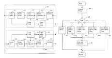
- FIG. 3is a block diagram of a communication network node in accordance with aspects of the invention.
- the nodeincludes a first PHY 301 and a second PHY 303 that transmit and receive signals from a first physical media link 341 and a second physical media link 343 , respectively.
- Each PHYis additionally coupled to a higher-layer processing block 331 .
- the nodeincludes a local clock 321 .
- Each PHYincludes a transmit block and receive block, for example, as described with reference to FIGS. 1 and 2 .
- the nodemay be provided as an integrated circuit.
- the PHYshandle timestamp processing and may be used to add clock synchronization to a network without substantial modification of other components.
- FIG. 4is a flowchart of a process for handling timing information in accordance with aspects of the invention.
- the processmay be implemented by a PHY device, for example, the device of FIG. 1 .
- the process embodiment illustrated in FIG. 4corresponds to processing performed by the receive block 100 of FIG. 1 .
- Other embodimentsare essentially similar but may have, for example, a different number of packet classifications.
- the processclassifies a packet received as an input to the process.
- the classificationis according to the type of timestamp processing to be performed by the process. Packets may additionally be classified according to the communication format used, the timestamp protocol used, the type of operation being performed with respect to the packet, or a combination thereof. For example, in some embodiments, a received packet for an IEEE 1588 timestamp protocol may be classified as a type C packet and packet to be transmitted for an IEEE 1588 protocol may be classified as a type D packet.
- the processtests the type of packet classified in block 401 . If the classification is type A, the process continues to block 411 . If the classification is type B, the process continues to block 412 . If the classification is type C, the process continues to block 413 . If the classification is type D, the process continues to block 414 . If the classification is type E, the process continues to block 415 . In an embodiment with a different classification scheme, correspondingly different branches would be taken in block 405 .
- Type A packetsare a classification that do not receive timestamp processing. The process thereafter returns.
- the processsupplies a new timestamp with a value from a local clock.
- the valuemay be adjusted to compensate for delays in processing.
- the processthen continues to block 421 .
- the processsupplies a new timestamp using a timestamp value from the received packet, a value from a local clock, and an offset value.
- the new timestamphas a value that is the value from the received packet minus the value from the local clock plus the offset value.
- the value from the local clockmay be adjusted to compensate for delays in processing.
- the offset valuemay correspond to a delay over a link supplying the packet to the process.
- the processsupplies a new timestamp in manner similar to block 413 .
- the new timestamphas a value that is the value from the received packet plus the value from the local clock plus the offset value. The process then continues to block 421 .
- the processsupplies a new timestamp with a value from a local clock.
- the valuemay be adjusted to compensate for delays in processing.
- the packet, or an identifier of the packet, and the new timestamp valueare saved for subsequent processing, and in many embodiments the packet is forwarded through for subsequent processing.
- a higher-layer devicemay use the packet and the new timestamp value to process a packet with a message signaling timing information for a boundary clock.
- packets processed in block 411 - 414may also be forwarded to higher-layer device, for example, for routing. However, in many embodiments generally the higher-layer device does not perform further processing of timing information. The process thereafter returns.
- the processwrites the new timestamp value into the packet.
- the valuemay be written to a fixed location in the packet with the location defined by the format of the packet.
- the processalso writes a checksum-type value in the packet. For example, for an Ethernet format packet, the process may update the frame check sequence (FCS) to reflect the new timestamp value. The process thereafter returns.
- FCSframe check sequence
- the process illustrated in FIG. 4may be performed twice within a network device for a given packet, upon ingress of the packet and upon egress of the packet.
- the classification of the packetmay differ between ingress and egress with a corresponding different branch taken from decision block 405 .
- the ingress processmay perform block 513 and the egress process may perform block 514 with an offset value of zero in both.
- the ingress processproduces a timestamp value with the value of the local clock, the receipt time, subtracted from the timestamp in the received frame.
- the egress processproduces a timestamp value with the value of the local clock, the transmit time, added to the timestamp produced by the ingress process.
- the combined processesproduce a timestamp value that is the timestamp in the received frame plus the residence time in the network device.
- the ingress and egress processesmay be performed by an ingress PHY and an egress PHY in the network device and provide processing of the timing information without a involvement of a higher-level device, although a higher-level device will generally be used to route packets between the ingress and egress PHYs. This example may be termed one-step operation since the time values are included in the packets to which they relate.
- a further example of use of the process illustrated in FIG. 4is for transmission of an IEEE 1588 Sync message from a network device providing a master clock.
- the network devicefor example, in a processor, creates information of a first packet containing a Sync message.
- the first packetis acted upon by an embodiment of the process, with the process for example performed by a PHY.
- the first packetis classified as type E so that block 415 is performed.
- the processsaves an identifier of the packet along with time of transmission of the packet.
- the processorreads the saved information and creates a second packet containing a Followup message.
- the Followup messageincludes the time of transmission of the first packet, which included the Sync message.
- the second packetis supplied to a second embodiment of the process.
- the second packetis classified as type A so that block 411 is performed.
- the processforwards the packet for transmission without timestamp processing. This example may be termed two-step operation since the time value that relates to one packet is transmitted in second packet
- a further example of use of the process illustrated in FIG. 4is for delay measurements according to ITU-T Y.1731.
- the measurementsmay be one-way delay measurements or two-way delay measurements.
- a first network devicesends a delay measurement packet containing a timestamp indicating transmission time to a second network device.
- the second network devicemeasures the delay using the time it receives the packet and the transmit timestamp. Accordingly, the process may be performed twice, for the transmission time and for the reception time, for a one-way delay measurement.
- An implementation of the process by a PHY device in the first network deviceclassifies a delay measurement packet as type B.
- the processin block 412 , supplies a timestamp indicating the transmission time of the packet and, in block 421 , writes the transmit timestamp into the packet at a first reserved location before or while the packet is transmitted to the second network device.
- an implementation of the process by a PHY device in the second network devicealso classifies the packet as type B.
- the process, in block 412supplies a timestamp indicating arrival time of the packet and, in block 421 , writes the receive timestamp into the packet at a second reserved location.
- the packetwhich contains the transmission time and arrival time, may then be supplied to a processor in the second network device to calculate the delay.
- a first network devicesends a delay measurement request packet containing a timestamp indicating transmission time to a second network device.
- the second network deviceresponds by sending a reply packet to the first network device.
- the reply packethas a reception timestamp (indicating when the request packet is received by the second network device) and a transmission timestamp (indicating when the reply packet is transmitted by the second network device) inserted.
- the first network devicemeasures the two-way delay using the time it receives the reply packet and the other timestamps in the reply packet. Accordingly, the process of FIG. 4 may be performed four times, once for each of the transmission and reception times, for a two-way delay measurement. Note that unlike one-way delay measurements, where the two network devices are synchronized to a common time base, two-way delay measurements may be performed when the two network devices lack a common time base.
- An implementation of the process by a PHY device in the first network deviceclassifies the request packet as type B.
- the processin block 412 , supplies a timestamp indicating transmission time of the request packet and, in block 421 , writes the transmit timestamp into the request packet at a first reserved location before or while the packet is transmitted to the second network device.
- an implementation of the process by a PHY device in the second network deviceclassifies the packet as type B.
- the process, in block 412supplies a timestamp indicating arrival time of the packet and, in block 421 , writes the receive timestamp into the packet at a second reserved location.
- the packetwhich contains the transmission time and reception time, may then be supplied to a processor in the second network device to form the reply packet, for example, including swapping source and destination address in the request packet and setting an opcode to signal a reply.
- Another implementation of the process by the PHY device in the second network deviceclassifies the reply packet as type B.
- the processin block 412 , supplies a timestamp indicating transmission time of the reply packet and, in block 421 , writes the transmit timestamp into the reply packet at a third reserved location before or while the packet is transmitted to the first network device.
- the processin block 412 , supplies a timestamp indicating arrival time of the reply packet and, in block 421 , writes the receive timestamp into the reply packet at a fourth reserved location.
- the reply packetwhich contains the transmission time and reception time of the request and the transmission time and reception time of the reply, may then be supplied to a processor in the first network device to calculate the delay.
- the location at which the reception or transmission time value is written in the packetsdiffers in each case depending on the type of delay measurement and whether the process was performing for a packet transmission or reception.
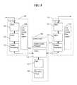
- FIG. 5is a block diagram of a communication system in accordance with aspects of the invention.
- the communication systemhandles timing information, for example, according to IEEE 1588 and ITU-T Y.1731.
- the systemincludes a first line card 501 and a second line card 511 .
- the first line cardincludes a PHY 503 that provides timestamp processing.
- the PHYmay be one of the PHYs described with reference to FIGS. 1 and 2 .
- the PHYis coupled to a MAC 505 which is coupled to a packet processing module 507 . Operation of the first line card is controlled and monitored by a line card control processor 509 .
- the second line card 511includes corresponding blocks and in some embodiments is the same as the first line card.
- FIG. 5shows two line cards but a system may include many more line cards.
- a system card 541is coupled to the first and second line cards.
- a switch fabric 545couples the line cards and switches packets between line cards.
- a system control processor 543controls and monitors operation of the system card.
- the system cardincludes a PHY 547 .
- the PHYprovide timestamp processing and may be one of the PHYs described with reference to FIGS. 1 and 2 .
- the system cardsinclude a boundary clock 549 .
- the boundary clockprovides a clock local to the system card that is synchronized to a master clock in the communication network.
- the boundary clockserves as a master clock to other devices.
- an embodiment of the system without a boundary clockmay not serve as a master clock to other devices, it may handle timing information, for example, processing packets for transparent clock according to IEEE 1588. Time values from the boundary clock are provided to the switch fabric by way of the PHY 547 .
- a component of the system cardfor example, the system control processor, provides to the PHY a signal indicative of receipt and transmission of a packet by components of the system card with the PHY performing timestamp operations based on the signals.
- the PHYmay be used to couple signals into and out of the system card, and thereby be able to provide timestamp related processing including determining time of receipt, time of transmission, and residence time of packets processed by the system card.
Landscapes
- Engineering & Computer Science (AREA)
- Computer Networks & Wireless Communication (AREA)
- Signal Processing (AREA)
- Health & Medical Sciences (AREA)
- Cardiology (AREA)
- General Health & Medical Sciences (AREA)
- Environmental & Geological Engineering (AREA)
- Data Exchanges In Wide-Area Networks (AREA)
- Synchronisation In Digital Transmission Systems (AREA)
- Computer And Data Communications (AREA)
Abstract
Description
Claims (27)
Priority Applications (1)
| Application Number | Priority Date | Filing Date | Title |
|---|---|---|---|
| US13/039,199US8571014B2 (en) | 2010-03-02 | 2011-03-02 | Distributed packet-based timestamp engine |
Applications Claiming Priority (2)
| Application Number | Priority Date | Filing Date | Title |
|---|---|---|---|
| US30980310P | 2010-03-02 | 2010-03-02 | |
| US13/039,199US8571014B2 (en) | 2010-03-02 | 2011-03-02 | Distributed packet-based timestamp engine |
Publications (2)
| Publication Number | Publication Date |
|---|---|
| US20120014377A1 US20120014377A1 (en) | 2012-01-19 |
| US8571014B2true US8571014B2 (en) | 2013-10-29 |
Family
ID=44542827
Family Applications (1)
| Application Number | Title | Priority Date | Filing Date |
|---|---|---|---|
| US13/039,199ActiveUS8571014B2 (en) | 2010-03-02 | 2011-03-02 | Distributed packet-based timestamp engine |
Country Status (5)
| Country | Link |
|---|---|
| US (1) | US8571014B2 (en) |
| CN (1) | CN102783079B (en) |
| DE (1) | DE112011100762B4 (en) |
| GB (1) | GB2490833B (en) |
| WO (1) | WO2011109539A2 (en) |
Cited By (9)
| Publication number | Priority date | Publication date | Assignee | Title |
|---|---|---|---|---|
| US20150055644A1 (en)* | 2013-08-22 | 2015-02-26 | Lsi Corporation | Precise timestamping of ethernet packets by compensating for start-of-frame delimiter detection delay and delay variations |
| US20150085879A1 (en)* | 2013-09-25 | 2015-03-26 | International Business Machines Corporation | Memory Transfer Optimization of Network Adapter Data Placement when Performing Header-Data Split Operations |
| US20150093109A1 (en)* | 2013-09-30 | 2015-04-02 | Vitesse Semiconductor Corporation | Ptp transparent clock system upgrade solution |
| US9264333B1 (en) | 2011-07-01 | 2016-02-16 | Marvell Israel (M.I.S.L) Ltd. | Checksum trailer in timing protocols |
| EP3151452A1 (en)* | 2015-09-30 | 2017-04-05 | Alcatel Lucent | Network node of a telecommunications network |
| WO2019055196A1 (en) | 2017-09-18 | 2019-03-21 | Microsemi Storage Solutions, Inc. | Packet classification and timestamping system and method |
| US10651974B2 (en) | 2017-02-28 | 2020-05-12 | Marvell Asia Pte, Ltd. | Method and apparatus for updating error detection information in packets |
| US10892972B2 (en) | 2017-04-26 | 2021-01-12 | Microsemi Storage Solutions, Inc. | Scheduled network setup test method and system |
| US11271712B2 (en) | 2020-01-07 | 2022-03-08 | Microchip Technology Inc. | Daisy-chained synchronous ethernet clock recovery |
Families Citing this family (71)
| Publication number | Priority date | Publication date | Assignee | Title |
|---|---|---|---|---|
| CN101615963B (en)* | 2008-06-23 | 2012-12-12 | 华为技术有限公司 | Method and system for processing correction domain information |
| US8670466B1 (en)* | 2010-12-22 | 2014-03-11 | Applied Micro Circuits Corporation | System and method for residence time calculation |
| EP2530860B1 (en)* | 2011-06-01 | 2017-05-17 | ADVA Optical Networking SE | A method and apparatus for transporting time related information in a packet switched network |
| US9282024B2 (en) | 2011-11-07 | 2016-03-08 | Microsemi Communications, Inc. | Physical layer processing of timestamps and MAC security |
| US8837650B2 (en) | 2012-05-29 | 2014-09-16 | Magnolia Broadband Inc. | System and method for discrete gain control in hybrid MIMO RF beamforming for multi layer MIMO base station |
| US8811522B2 (en) | 2012-05-29 | 2014-08-19 | Magnolia Broadband Inc. | Mitigating interferences for a multi-layer MIMO system augmented by radio distribution network |
| US8619927B2 (en) | 2012-05-29 | 2013-12-31 | Magnolia Broadband Inc. | System and method for discrete gain control in hybrid MIMO/RF beamforming |
| US8767862B2 (en) | 2012-05-29 | 2014-07-01 | Magnolia Broadband Inc. | Beamformer phase optimization for a multi-layer MIMO system augmented by radio distribution network |
| US8885757B2 (en) | 2012-05-29 | 2014-11-11 | Magnolia Broadband Inc. | Calibration of MIMO systems with radio distribution networks |
| US8649458B2 (en) | 2012-05-29 | 2014-02-11 | Magnolia Broadband Inc. | Using antenna pooling to enhance a MIMO receiver augmented by RF beamforming |
| US8644413B2 (en) | 2012-05-29 | 2014-02-04 | Magnolia Broadband Inc. | Implementing blind tuning in hybrid MIMO RF beamforming systems |
| US8861635B2 (en) | 2012-05-29 | 2014-10-14 | Magnolia Broadband Inc. | Setting radio frequency (RF) beamformer antenna weights per data-stream in a multiple-input-multiple-output (MIMO) system |
| US8842765B2 (en) | 2012-05-29 | 2014-09-23 | Magnolia Broadband Inc. | Beamformer configurable for connecting a variable number of antennas and radio circuits |
| US8971452B2 (en) | 2012-05-29 | 2015-03-03 | Magnolia Broadband Inc. | Using 3G/4G baseband signals for tuning beamformers in hybrid MIMO RDN systems |
| US9154204B2 (en) | 2012-06-11 | 2015-10-06 | Magnolia Broadband Inc. | Implementing transmit RDN architectures in uplink MIMO systems |
| US20130336129A1 (en)* | 2012-06-15 | 2013-12-19 | Fujitsu Limited | Multipurpose Use of Delay Measurement Message Buffer for Software Processing of Delay Measurement Response |
| WO2014001911A2 (en) | 2012-06-26 | 2014-01-03 | Marvell World Trade Ltd. | Methods and apparatus for precision time stamping |
| EP2680466A1 (en)* | 2012-06-26 | 2014-01-01 | ABB Research Ltd. | Low latency transparent clock |
| US10037346B1 (en)* | 2012-07-25 | 2018-07-31 | Google Llc | Time reservations for ensuring consistent reads in a distributed database without logging |
| US9450846B1 (en)* | 2012-10-17 | 2016-09-20 | Cisco Technology, Inc. | System and method for tracking packets in a network environment |
| US8797969B1 (en) | 2013-02-08 | 2014-08-05 | Magnolia Broadband Inc. | Implementing multi user multiple input multiple output (MU MIMO) base station using single-user (SU) MIMO co-located base stations |
| US9343808B2 (en) | 2013-02-08 | 2016-05-17 | Magnotod Llc | Multi-beam MIMO time division duplex base station using subset of radios |
| US8774150B1 (en) | 2013-02-13 | 2014-07-08 | Magnolia Broadband Inc. | System and method for reducing side-lobe contamination effects in Wi-Fi access points |
| US20140226740A1 (en) | 2013-02-13 | 2014-08-14 | Magnolia Broadband Inc. | Multi-beam co-channel wi-fi access point |
| US9155110B2 (en)* | 2013-03-27 | 2015-10-06 | Magnolia Broadband Inc. | System and method for co-located and co-channel Wi-Fi access points |
| US8989103B2 (en) | 2013-02-13 | 2015-03-24 | Magnolia Broadband Inc. | Method and system for selective attenuation of preamble reception in co-located WI FI access points |
| CN104113517A (en) | 2013-04-22 | 2014-10-22 | 华为技术有限公司 | Timestamp generation method, device and system |
| US9100968B2 (en) | 2013-05-09 | 2015-08-04 | Magnolia Broadband Inc. | Method and system for digital cancellation scheme with multi-beam |
| US9425882B2 (en) | 2013-06-28 | 2016-08-23 | Magnolia Broadband Inc. | Wi-Fi radio distribution network stations and method of operating Wi-Fi RDN stations |
| US8995416B2 (en) | 2013-07-10 | 2015-03-31 | Magnolia Broadband Inc. | System and method for simultaneous co-channel access of neighboring access points |
| US8824596B1 (en) | 2013-07-31 | 2014-09-02 | Magnolia Broadband Inc. | System and method for uplink transmissions in time division MIMO RDN architecture |
| US9497781B2 (en) | 2013-08-13 | 2016-11-15 | Magnolia Broadband Inc. | System and method for co-located and co-channel Wi-Fi access points |
| US9060362B2 (en) | 2013-09-12 | 2015-06-16 | Magnolia Broadband Inc. | Method and system for accessing an occupied Wi-Fi channel by a client using a nulling scheme |
| US9088898B2 (en) | 2013-09-12 | 2015-07-21 | Magnolia Broadband Inc. | System and method for cooperative scheduling for co-located access points |
| KR101974323B1 (en)* | 2013-10-30 | 2019-04-30 | 인텔 코포레이션 | A method, apparatus and system for measuring latency in a physical unit of a circuit |
| US9172454B2 (en) | 2013-11-01 | 2015-10-27 | Magnolia Broadband Inc. | Method and system for calibrating a transceiver array |
| US8891598B1 (en) | 2013-11-19 | 2014-11-18 | Magnolia Broadband Inc. | Transmitter and receiver calibration for obtaining the channel reciprocity for time division duplex MIMO systems |
| US8942134B1 (en) | 2013-11-20 | 2015-01-27 | Magnolia Broadband Inc. | System and method for selective registration in a multi-beam system |
| US8929322B1 (en) | 2013-11-20 | 2015-01-06 | Magnolia Broadband Inc. | System and method for side lobe suppression using controlled signal cancellation |
| US9014066B1 (en) | 2013-11-26 | 2015-04-21 | Magnolia Broadband Inc. | System and method for transmit and receive antenna patterns calibration for time division duplex (TDD) systems |
| US9294177B2 (en) | 2013-11-26 | 2016-03-22 | Magnolia Broadband Inc. | System and method for transmit and receive antenna patterns calibration for time division duplex (TDD) systems |
| US9042276B1 (en) | 2013-12-05 | 2015-05-26 | Magnolia Broadband Inc. | Multiple co-located multi-user-MIMO access points |
| US9100154B1 (en) | 2014-03-19 | 2015-08-04 | Magnolia Broadband Inc. | Method and system for explicit AP-to-AP sounding in an 802.11 network |
| US9172446B2 (en) | 2014-03-19 | 2015-10-27 | Magnolia Broadband Inc. | Method and system for supporting sparse explicit sounding by implicit data |
| US9271176B2 (en) | 2014-03-28 | 2016-02-23 | Magnolia Broadband Inc. | System and method for backhaul based sounding feedback |
| US9641416B2 (en)* | 2014-04-18 | 2017-05-02 | Cisco Technology, Inc. | Operations analysis of packet groups identified based on timestamps |
| GB2525929B (en)* | 2014-05-09 | 2016-08-10 | Imagination Tech Ltd | Time stamp replication within a wireless network |
| CN105262555B (en)* | 2014-07-16 | 2021-05-28 | 中兴通讯股份有限公司 | Time synchronization method, programmable logic device, single board and network element |
| EP2978180A1 (en)* | 2014-07-22 | 2016-01-27 | Alcatel Lucent | Signaling for transmission of coherent data flow within packet-switched network |
| CN105281885B (en)* | 2014-07-25 | 2021-04-16 | 中兴通讯股份有限公司 | Time synchronization method and device for network equipment and time synchronization server |
| US9483209B2 (en) | 2014-09-22 | 2016-11-01 | Freescale Semiconductor, Inc. | Interface system and method |
| US9838311B2 (en)* | 2015-01-30 | 2017-12-05 | Huawei Technologies Co., Ltd. | Node, network controller, and associated methods for routing data packets in a network |
| US10200438B2 (en)* | 2016-01-15 | 2019-02-05 | Pathsolutions, Inc. | Test for preservation of differentiated service in an internet protocol network |
| US10104148B2 (en)* | 2017-01-03 | 2018-10-16 | Globalfoundries Inc. | Nanosecond accuracy under precision time protocol for ethernet by using high accuracy timestamp assist device |
| EP3659278B1 (en) | 2017-07-26 | 2024-02-21 | Aviat Networks, Inc. | Distributed radio transparent clock over a wireless network |
| US10868623B2 (en) | 2017-07-26 | 2020-12-15 | Aviat U.S., Inc. | Airframe timestamping technique for point-to-point radio links |
| US10809760B1 (en)* | 2018-10-29 | 2020-10-20 | Facebook, Inc. | Headset clock synchronization |
| US11689440B2 (en) | 2019-02-06 | 2023-06-27 | Marvell Israel (M.I.S.L) Ltd. | Method and apparatus for transmit time timestamping |
| CN112583775B (en)* | 2019-09-30 | 2024-04-12 | 华为技术有限公司 | Method, device and network equipment for processing message |
| US11552871B2 (en)* | 2020-06-14 | 2023-01-10 | Mellanox Technologies, Ltd. | Receive-side timestamp accuracy |
| JP7136175B2 (en)* | 2020-12-22 | 2022-09-13 | カシオ計算機株式会社 | Data processing device, electronic equipment, data processing method and program |
| JP7665398B2 (en) | 2021-04-26 | 2025-04-21 | キヤノン株式会社 | COMMUNICATION DEVICE, CONTROL METHOD AND PROGRAM FOR COMMUNICATION DEVICE |
| US12160309B1 (en) | 2021-05-28 | 2024-12-03 | Marvell Israel (M.I.S.L) Ltd. | Timestamping for multiple synchronization domains in a network device |
| US11811637B1 (en)* | 2021-11-24 | 2023-11-07 | Amazon Technologies, Inc. | Packet timestamp format manipulation |
| US12373235B1 (en) | 2021-12-07 | 2025-07-29 | Amazon Technologies, Inc. | Physical hardware clock virtualization |
| US12074693B2 (en) | 2022-02-24 | 2024-08-27 | Marvell Israel (M.I.S.L) Ltd. | Dynamic one-step/two-step timestamping per packet in network devices |
| US12101240B2 (en) | 2022-02-24 | 2024-09-24 | Marvell Israel (M.I.S.L) Ltd. | Dynamic one-step/two-step timestamping per packet in network devices |
| US12107671B2 (en) | 2022-02-24 | 2024-10-01 | Marvell Israel (M.I.S.L) Ltd. | Timestamping over media independent interfaces |
| US11924318B2 (en) | 2022-02-24 | 2024-03-05 | Marvell Israel (M.I.S.L) Ltd. | Timestamping for multiple synchronization domains in a network device |
| TW202429845A (en)* | 2022-09-08 | 2024-07-16 | 美商微晶片科技公司 | System and methods for network data processing |
| US12294451B2 (en) | 2022-09-08 | 2025-05-06 | Microchip Technology Incorporated | System and methods for network data processing |
Citations (25)
| Publication number | Priority date | Publication date | Assignee | Title |
|---|---|---|---|---|
| US4736019A (en)* | 1985-05-31 | 1988-04-05 | Commissariat A L'energie Atomique | Process for the separation of antifactor VIII:C antibodies, more particularly usable for the purification of the blood plasma of a type a hemophiliac |
| US4894823A (en)* | 1986-02-28 | 1990-01-16 | American Telephone And Telegraph Company | Time stamping for packet system nodes |
| US20020024970A1 (en)* | 2000-04-07 | 2002-02-28 | Amaral John M. | Transmitting MPEG data packets received from a non-constant delay network |
| US20020027886A1 (en) | 2000-04-07 | 2002-03-07 | Fischer Matthew James | Method of controlling data sampling clocking of asynchronous network nodes in a frame-based communications network |
| US20020085582A1 (en)* | 2000-12-28 | 2002-07-04 | Lg Electronics Inc. | System and method for processing multimedia packets for a network |
| US20030095551A1 (en)* | 2001-11-19 | 2003-05-22 | Hiroki Gotoh | Packet transmission apparatus and packet transmission processing method |
| US20040062278A1 (en)* | 2002-09-30 | 2004-04-01 | Lucent Technologies, Inc. | Systems and methods for synchronization in asynchronous transport networks |
| US6845100B1 (en)* | 2000-08-28 | 2005-01-18 | Nokia Mobile Phones Ltd. | Basic QoS mechanisms for wireless transmission of IP traffic |
| US20050039065A1 (en)* | 2003-08-15 | 2005-02-17 | Francis Cheung | System and method for generating multiple independent, synchronized local timestamps |
| US20050036512A1 (en)* | 2003-08-14 | 2005-02-17 | Dmitrii Loukianov | Timestamping network controller for streaming media applications |
| US20050058149A1 (en) | 1998-08-19 | 2005-03-17 | Howe Wayne Richard | Time-scheduled and time-reservation packet switching |
| US20050135429A1 (en) | 2003-11-19 | 2005-06-23 | Bingham David T. | Time and data synchronization between network devices |
| US20060056432A1 (en)* | 2004-09-14 | 2006-03-16 | Maksim Azarov | System and method for varying the scheduling of real time protocol (RTP) packets |
| US20060203851A1 (en) | 2005-03-14 | 2006-09-14 | Eidson John C | Applications of multiple time synchronization domains |
| US20060256820A1 (en) | 2005-05-12 | 2006-11-16 | Ilnicki Slawomir K | Systems and methods for synchronizing time across networks |
| US20060280182A1 (en)* | 2005-04-22 | 2006-12-14 | National Ict Australia Limited | Method for transporting digital media |
| US7215637B1 (en)* | 2000-04-17 | 2007-05-08 | Juniper Networks, Inc. | Systems and methods for processing packets |
| US20070147435A1 (en)* | 2005-12-23 | 2007-06-28 | Bruce Hamilton | Removing delay fluctuation in network time synchronization |
| US7292537B2 (en)* | 2002-11-29 | 2007-11-06 | Alcatel Lucent | Measurement architecture to obtain per-hop one-way packet loss and delay in multi-class service networks |
| US20080089364A1 (en)* | 2006-08-22 | 2008-04-17 | Brilliant Telecommunications, Inc. | Apparatus and method of controlled delay packet forwarding |
| US20080181112A1 (en)* | 2007-01-31 | 2008-07-31 | Juergen Beck | Methods and Apparatus for Controlling Latency Variation in a Packet Transfer Network |
| US20090053431A1 (en)* | 2002-06-10 | 2009-02-26 | Koenig Michael F | Waterfast dye fixative compositions for ink jet recording sheets |
| US7656947B2 (en)* | 2005-10-11 | 2010-02-02 | Samsung Electronics Co., Ltd. | Synchronization device and synchronization method in digital broadcast receiver |
| US7689854B2 (en) | 2006-09-22 | 2010-03-30 | Agilent Technologies, Inc. | Method and apparatus for establishing IEEE 1588 clock synchronization across a network element comprising first and second cooperating smart interface converters wrapping the network element |
| US7787438B2 (en)* | 2006-12-22 | 2010-08-31 | Corvil Limited | Delay measurements in network traffic |
Family Cites Families (6)
| Publication number | Priority date | Publication date | Assignee | Title |
|---|---|---|---|---|
| EP1283611A3 (en)* | 2001-08-09 | 2006-02-15 | Siemens Aktiengesellschaft | Method for synchronization of a communication system via a packet oriented data network |
| US20030219007A1 (en)* | 2002-05-23 | 2003-11-27 | Craig Barrack | Reusable multi-protocol meta-architecture for Voice-over-IP playback |
| CN101355531A (en)* | 2008-09-24 | 2009-01-28 | 华为技术有限公司 | Method, device and equipment for sending and receiving messages |
| CN101447861B (en)* | 2008-12-29 | 2011-10-26 | 中兴通讯股份有限公司 | IEEE 1588 time synchronization system and implementation method thereof |
| CN101478359B (en)* | 2009-01-16 | 2013-01-23 | 华为技术有限公司 | Method, apparatus and system for managing IEEE1588 timestamp |
| CN101594673B (en)* | 2009-06-29 | 2011-05-11 | 中兴通讯股份有限公司 | Method and system for processing 1588 time stamp in distribution mode |
- 2011
- 2011-03-02USUS13/039,199patent/US8571014B2/enactiveActive
- 2011-03-02WOPCT/US2011/026894patent/WO2011109539A2/enactiveApplication Filing
- 2011-03-02GBGB1215066.0Apatent/GB2490833B/enactiveActive
- 2011-03-02DEDE112011100762.0Tpatent/DE112011100762B4/enactiveActive
- 2011-03-02CNCN201180011908.7Apatent/CN102783079B/enactiveActive
Patent Citations (26)
| Publication number | Priority date | Publication date | Assignee | Title |
|---|---|---|---|---|
| US4736019A (en)* | 1985-05-31 | 1988-04-05 | Commissariat A L'energie Atomique | Process for the separation of antifactor VIII:C antibodies, more particularly usable for the purification of the blood plasma of a type a hemophiliac |
| US4894823A (en)* | 1986-02-28 | 1990-01-16 | American Telephone And Telegraph Company | Time stamping for packet system nodes |
| US20050058149A1 (en) | 1998-08-19 | 2005-03-17 | Howe Wayne Richard | Time-scheduled and time-reservation packet switching |
| US20020024970A1 (en)* | 2000-04-07 | 2002-02-28 | Amaral John M. | Transmitting MPEG data packets received from a non-constant delay network |
| US20020027886A1 (en) | 2000-04-07 | 2002-03-07 | Fischer Matthew James | Method of controlling data sampling clocking of asynchronous network nodes in a frame-based communications network |
| US7215637B1 (en)* | 2000-04-17 | 2007-05-08 | Juniper Networks, Inc. | Systems and methods for processing packets |
| US6845100B1 (en)* | 2000-08-28 | 2005-01-18 | Nokia Mobile Phones Ltd. | Basic QoS mechanisms for wireless transmission of IP traffic |
| US20020085582A1 (en)* | 2000-12-28 | 2002-07-04 | Lg Electronics Inc. | System and method for processing multimedia packets for a network |
| US20030095551A1 (en)* | 2001-11-19 | 2003-05-22 | Hiroki Gotoh | Packet transmission apparatus and packet transmission processing method |
| US20090053431A1 (en)* | 2002-06-10 | 2009-02-26 | Koenig Michael F | Waterfast dye fixative compositions for ink jet recording sheets |
| US20040062278A1 (en)* | 2002-09-30 | 2004-04-01 | Lucent Technologies, Inc. | Systems and methods for synchronization in asynchronous transport networks |
| US7292537B2 (en)* | 2002-11-29 | 2007-11-06 | Alcatel Lucent | Measurement architecture to obtain per-hop one-way packet loss and delay in multi-class service networks |
| US20050036512A1 (en)* | 2003-08-14 | 2005-02-17 | Dmitrii Loukianov | Timestamping network controller for streaming media applications |
| US20050039065A1 (en)* | 2003-08-15 | 2005-02-17 | Francis Cheung | System and method for generating multiple independent, synchronized local timestamps |
| US20050135429A1 (en) | 2003-11-19 | 2005-06-23 | Bingham David T. | Time and data synchronization between network devices |
| US20060056432A1 (en)* | 2004-09-14 | 2006-03-16 | Maksim Azarov | System and method for varying the scheduling of real time protocol (RTP) packets |
| US20060203851A1 (en) | 2005-03-14 | 2006-09-14 | Eidson John C | Applications of multiple time synchronization domains |
| US20060280182A1 (en)* | 2005-04-22 | 2006-12-14 | National Ict Australia Limited | Method for transporting digital media |
| US7747725B2 (en)* | 2005-04-22 | 2010-06-29 | Audinate Pty. Limited | Method for transporting digital media |
| US20060256820A1 (en) | 2005-05-12 | 2006-11-16 | Ilnicki Slawomir K | Systems and methods for synchronizing time across networks |
| US7656947B2 (en)* | 2005-10-11 | 2010-02-02 | Samsung Electronics Co., Ltd. | Synchronization device and synchronization method in digital broadcast receiver |
| US20070147435A1 (en)* | 2005-12-23 | 2007-06-28 | Bruce Hamilton | Removing delay fluctuation in network time synchronization |
| US20080089364A1 (en)* | 2006-08-22 | 2008-04-17 | Brilliant Telecommunications, Inc. | Apparatus and method of controlled delay packet forwarding |
| US7689854B2 (en) | 2006-09-22 | 2010-03-30 | Agilent Technologies, Inc. | Method and apparatus for establishing IEEE 1588 clock synchronization across a network element comprising first and second cooperating smart interface converters wrapping the network element |
| US7787438B2 (en)* | 2006-12-22 | 2010-08-31 | Corvil Limited | Delay measurements in network traffic |
| US20080181112A1 (en)* | 2007-01-31 | 2008-07-31 | Juergen Beck | Methods and Apparatus for Controlling Latency Variation in a Packet Transfer Network |
Non-Patent Citations (5)
| Title |
|---|
| Eidson et al., (2008). International IEEE Symposium on Precision Clock Synchronization for Measurement, Control and Communication. ISPCS 2008. Spider Transparent Clock. Sep. 22-26, 2008. Ann Arbor, Michigan. |
| Garner et al., (2010). International IEEE Symposium on Precision Clock Synchronization for Measurement, Control and communication. ISPCS 2010. Using an IEEE 802.1AS Network as a Distributed IEEE 1588 Boundary, Ordinary, or Transparent Clock. Sep. 27, 2010-Oct. 1, 2010. Portsmouth, New Hampshire. |
| International Search Report on corresponding PCT application (PCT/US2011/026894) from International Searching Authority (KR) dated Oct. 25, 2011. |
| Prof. Hans Weibel, Zurich University of Applied Sciences: Tutorial at the 2006 Conference on IEEE 1588; Oct. 2006. |
| Written Opinion on corresponding PCT application (PCT/US2011/026894) from International Searching Authority (KR) dated Oct. 25, 2011. |
Cited By (16)
| Publication number | Priority date | Publication date | Assignee | Title |
|---|---|---|---|---|
| US9264333B1 (en) | 2011-07-01 | 2016-02-16 | Marvell Israel (M.I.S.L) Ltd. | Checksum trailer in timing protocols |
| US20150055644A1 (en)* | 2013-08-22 | 2015-02-26 | Lsi Corporation | Precise timestamping of ethernet packets by compensating for start-of-frame delimiter detection delay and delay variations |
| US20150085879A1 (en)* | 2013-09-25 | 2015-03-26 | International Business Machines Corporation | Memory Transfer Optimization of Network Adapter Data Placement when Performing Header-Data Split Operations |
| US9270620B2 (en)* | 2013-09-25 | 2016-02-23 | International Business Machines Corporation | Memory transfer optimization of network adapter data placement when performing header-data split operations |
| US9276879B2 (en) | 2013-09-25 | 2016-03-01 | International Business Machines Corporation | Memory transfer optimization of network adapter data placement when performing header-data split operations |
| US20150093109A1 (en)* | 2013-09-30 | 2015-04-02 | Vitesse Semiconductor Corporation | Ptp transparent clock system upgrade solution |
| US9432751B2 (en)* | 2013-09-30 | 2016-08-30 | Microsemi Communications, Inc. | PTP transparent clock system upgrade solution |
| US10257595B2 (en) | 2013-09-30 | 2019-04-09 | Ip Gem Group, Llc | PTP transparent clock system upgrade solution |
| EP3151452A1 (en)* | 2015-09-30 | 2017-04-05 | Alcatel Lucent | Network node of a telecommunications network |
| US10651974B2 (en) | 2017-02-28 | 2020-05-12 | Marvell Asia Pte, Ltd. | Method and apparatus for updating error detection information in packets |
| US10892972B2 (en) | 2017-04-26 | 2021-01-12 | Microsemi Storage Solutions, Inc. | Scheduled network setup test method and system |
| WO2019055196A1 (en) | 2017-09-18 | 2019-03-21 | Microsemi Storage Solutions, Inc. | Packet classification and timestamping system and method |
| DE112018005252T5 (en) | 2017-09-18 | 2020-06-18 | Microsemi Storage Solutions, Inc. | SYSTEM AND METHOD FOR CLASSIFYING AND STAMPING PACKAGES |
| US10887211B2 (en) | 2017-09-18 | 2021-01-05 | Microsemi Storage Solutions, Inc. | Indirect packet classification timestamping system and method |
| CN111194529A (en)* | 2017-09-18 | 2020-05-22 | 美高森美存储解决方案股份有限公司 | Packet classification and time stamping system and method |
| US11271712B2 (en) | 2020-01-07 | 2022-03-08 | Microchip Technology Inc. | Daisy-chained synchronous ethernet clock recovery |
Also Published As
| Publication number | Publication date |
|---|---|
| GB201215066D0 (en) | 2012-10-10 |
| WO2011109539A3 (en) | 2011-12-29 |
| DE112011100762T5 (en) | 2012-12-13 |
| GB2490833A (en) | 2012-11-14 |
| GB2490833B (en) | 2016-02-24 |
| CN102783079B (en) | 2015-09-02 |
| CN102783079A (en) | 2012-11-14 |
| US20120014377A1 (en) | 2012-01-19 |
| DE112011100762B4 (en) | 2015-06-03 |
| WO2011109539A2 (en) | 2011-09-09 |
Similar Documents
| Publication | Publication Date | Title |
|---|---|---|
| US8571014B2 (en) | Distributed packet-based timestamp engine | |
| US10887211B2 (en) | Indirect packet classification timestamping system and method | |
| US9571376B2 (en) | Timestamp predictor for packets over a synchronous protocol | |
| EP2777211B1 (en) | Physical layer processing of timestamps and mac security | |
| US9860004B2 (en) | Network distributed packet-based synchronization | |
| US8879586B2 (en) | Inband timestamping | |
| US11349587B2 (en) | Generating a timestamp | |
| US20150063375A1 (en) | Communication device with peer-to-peer assist to provide synchronization | |
| EP2807785B1 (en) | Packet-based timing measurement | |
| KR20140111011A (en) | Method and apparatus for communicating time information between time-aware devices | |
| CN105706383A (en) | Pluggable transceivers for time synchronization | |
| CN114172604A (en) | Time delay compensation method, device, equipment and computer readable storage medium | |
| US20150010023A1 (en) | Packet protocol processing with precision timing protocol support | |
| CN111357243B (en) | User equipment of bus system, operation method and bus system | |
| KR20140065409A (en) | A system and a method for identifying a point in time of receipt of a data packet | |
| CN101420281B (en) | Method and arrangement for transferring a time of day value between network elements | |
| US9031063B2 (en) | Direct updating of network delay in synchronization packets | |
| JP2022025363A (en) | Time synchronization method, time synchronization program, time synchronization apparatus, and time synchronization system |
Legal Events
| Date | Code | Title | Description |
|---|---|---|---|
| AS | Assignment | Owner name:VITESSE SEMICONDUCTOR CORPORATION, CALIFORNIA Free format text:ASSIGNMENT OF ASSIGNORS INTEREST;ASSIGNORS:JOERGENSEN, THOMAS KIRKEGAARD;BRANSCOMB, BRIAN;EHLERS, KRISTIAN;SIGNING DATES FROM 20110914 TO 20110919;REEL/FRAME:026985/0409 | |
| STCF | Information on status: patent grant | Free format text:PATENTED CASE | |
| CC | Certificate of correction | ||
| AS | Assignment | Owner name:BANK OF AMERICA, N.A., AS COLLATERAL AGENT, NORTH Free format text:SUPPLEMENTAL SECURITY AGREEMENT;ASSIGNOR:MICROSEMI COMMUNICATIONS, INC.;REEL/FRAME:035532/0925 Effective date:20150428 | |
| AS | Assignment | Owner name:MICROSEMI COMMUNICATIONS, INC., CALIFORNIA Free format text:MERGER AND CHANGE OF NAME;ASSIGNORS:VITESSE SEMICONDUCTOR CORPORATION;LLIU100 ACQUISITION CORP.;REEL/FRAME:035651/0708 Effective date:20150428 | |
| AS | Assignment | Owner name:MICROSEMI CORP.-MEMORY AND STORAGE SOLUTIONS (F/K/ Free format text:RELEASE BY SECURED PARTY;ASSIGNOR:BANK OF AMERICA, N.A.;REEL/FRAME:037558/0711 Effective date:20160115 Owner name:MICROSEMI COMMUNICATIONS, INC. (F/K/A VITESSE SEMI Free format text:RELEASE BY SECURED PARTY;ASSIGNOR:BANK OF AMERICA, N.A.;REEL/FRAME:037558/0711 Effective date:20160115 Owner name:MICROSEMI SOC CORP., A CALIFORNIA CORPORATION, CAL Free format text:RELEASE BY SECURED PARTY;ASSIGNOR:BANK OF AMERICA, N.A.;REEL/FRAME:037558/0711 Effective date:20160115 Owner name:MICROSEMI CORPORATION, CALIFORNIA Free format text:RELEASE BY SECURED PARTY;ASSIGNOR:BANK OF AMERICA, N.A.;REEL/FRAME:037558/0711 Effective date:20160115 Owner name:MICROSEMI CORP.-ANALOG MIXED SIGNAL GROUP, A DELAW Free format text:RELEASE BY SECURED PARTY;ASSIGNOR:BANK OF AMERICA, N.A.;REEL/FRAME:037558/0711 Effective date:20160115 Owner name:MICROSEMI SEMICONDUCTOR (U.S.) INC., A DELAWARE CO Free format text:RELEASE BY SECURED PARTY;ASSIGNOR:BANK OF AMERICA, N.A.;REEL/FRAME:037558/0711 Effective date:20160115 Owner name:MICROSEMI FREQUENCY AND TIME CORPORATION, A DELAWA Free format text:RELEASE BY SECURED PARTY;ASSIGNOR:BANK OF AMERICA, N.A.;REEL/FRAME:037558/0711 Effective date:20160115 | |
| AS | Assignment | Owner name:MORGAN STANLEY SENIOR FUNDING, INC., NEW YORK Free format text:PATENT SECURITY AGREEMENT;ASSIGNORS:MICROSEMI CORPORATION;MICROSEMI SEMICONDUCTOR (U.S.) INC. (F/K/A LEGERITY, INC., ZARLINK SEMICONDUCTOR (V.N.) INC., CENTELLAX, INC., AND ZARLINK SEMICONDUCTOR (U.S.) INC.);MICROSEMI FREQUENCY AND TIME CORPORATION (F/K/A SYMMETRICON, INC.);AND OTHERS;REEL/FRAME:037691/0697 Effective date:20160115 | |
| FPAY | Fee payment | Year of fee payment:4 | |
| AS | Assignment | Owner name:MICROSEMI STORAGE SOLUTIONS, INC., CALIFORNIA Free format text:ASSIGNMENT OF ASSIGNORS INTEREST;ASSIGNOR:MICROSEMI COMMUNICATIONS, INC.;REEL/FRAME:042523/0577 Effective date:20160929 | |
| AS | Assignment | Owner name:MICROSEMI CORP. - RF INTEGRATED SOLUTIONS, CALIFOR Free format text:RELEASE BY SECURED PARTY;ASSIGNOR:MORGAN STANLEY SENIOR FUNDING, INC.;REEL/FRAME:046251/0391 Effective date:20180529 Owner name:MICROSEMI SEMICONDUCTOR (U.S.), INC., CALIFORNIA Free format text:RELEASE BY SECURED PARTY;ASSIGNOR:MORGAN STANLEY SENIOR FUNDING, INC.;REEL/FRAME:046251/0391 Effective date:20180529 Owner name:MICROSEMI FREQUENCY AND TIME CORPORATION, CALIFORN Free format text:RELEASE BY SECURED PARTY;ASSIGNOR:MORGAN STANLEY SENIOR FUNDING, INC.;REEL/FRAME:046251/0391 Effective date:20180529 Owner name:MICROSEMI SOC CORP., CALIFORNIA Free format text:RELEASE BY SECURED PARTY;ASSIGNOR:MORGAN STANLEY SENIOR FUNDING, INC.;REEL/FRAME:046251/0391 Effective date:20180529 Owner name:MICROSEMI CORP. - POWER PRODUCTS GROUP, CALIFORNIA Free format text:RELEASE BY SECURED PARTY;ASSIGNOR:MORGAN STANLEY SENIOR FUNDING, INC.;REEL/FRAME:046251/0391 Effective date:20180529 Owner name:MICROSEMI COMMUNICATIONS, INC., CALIFORNIA Free format text:RELEASE BY SECURED PARTY;ASSIGNOR:MORGAN STANLEY SENIOR FUNDING, INC.;REEL/FRAME:046251/0391 Effective date:20180529 Owner name:MICROSEMI CORPORATION, CALIFORNIA Free format text:RELEASE BY SECURED PARTY;ASSIGNOR:MORGAN STANLEY SENIOR FUNDING, INC.;REEL/FRAME:046251/0391 Effective date:20180529 | |
| AS | Assignment | Owner name:JPMORGAN CHASE BANK, N.A., AS ADMINISTRATIVE AGENT, ILLINOIS Free format text:SECURITY INTEREST;ASSIGNORS:MICROCHIP TECHNOLOGY INCORPORATED;SILICON STORAGE TECHNOLOGY, INC.;ATMEL CORPORATION;AND OTHERS;REEL/FRAME:046426/0001 Effective date:20180529 Owner name:JPMORGAN CHASE BANK, N.A., AS ADMINISTRATIVE AGENT Free format text:SECURITY INTEREST;ASSIGNORS:MICROCHIP TECHNOLOGY INCORPORATED;SILICON STORAGE TECHNOLOGY, INC.;ATMEL CORPORATION;AND OTHERS;REEL/FRAME:046426/0001 Effective date:20180529 | |
| AS | Assignment | Owner name:WELLS FARGO BANK, NATIONAL ASSOCIATION, AS NOTES COLLATERAL AGENT, CALIFORNIA Free format text:SECURITY INTEREST;ASSIGNORS:MICROCHIP TECHNOLOGY INCORPORATED;SILICON STORAGE TECHNOLOGY, INC.;ATMEL CORPORATION;AND OTHERS;REEL/FRAME:047103/0206 Effective date:20180914 Owner name:WELLS FARGO BANK, NATIONAL ASSOCIATION, AS NOTES C Free format text:SECURITY INTEREST;ASSIGNORS:MICROCHIP TECHNOLOGY INCORPORATED;SILICON STORAGE TECHNOLOGY, INC.;ATMEL CORPORATION;AND OTHERS;REEL/FRAME:047103/0206 Effective date:20180914 | |
| AS | Assignment | Owner name:JPMORGAN CHASE BANK, N.A., AS ADMINISTRATIVE AGENT, DELAWARE Free format text:SECURITY INTEREST;ASSIGNORS:MICROCHIP TECHNOLOGY INC.;SILICON STORAGE TECHNOLOGY, INC.;ATMEL CORPORATION;AND OTHERS;REEL/FRAME:053311/0305 Effective date:20200327 | |
| AS | Assignment | Owner name:ATMEL CORPORATION, ARIZONA Free format text:RELEASE BY SECURED PARTY;ASSIGNOR:JPMORGAN CHASE BANK, N.A, AS ADMINISTRATIVE AGENT;REEL/FRAME:053466/0011 Effective date:20200529 Owner name:MICROCHIP TECHNOLOGY INC., ARIZONA Free format text:RELEASE BY SECURED PARTY;ASSIGNOR:JPMORGAN CHASE BANK, N.A, AS ADMINISTRATIVE AGENT;REEL/FRAME:053466/0011 Effective date:20200529 Owner name:MICROSEMI STORAGE SOLUTIONS, INC., ARIZONA Free format text:RELEASE BY SECURED PARTY;ASSIGNOR:JPMORGAN CHASE BANK, N.A, AS ADMINISTRATIVE AGENT;REEL/FRAME:053466/0011 Effective date:20200529 Owner name:MICROSEMI CORPORATION, CALIFORNIA Free format text:RELEASE BY SECURED PARTY;ASSIGNOR:JPMORGAN CHASE BANK, N.A, AS ADMINISTRATIVE AGENT;REEL/FRAME:053466/0011 Effective date:20200529 Owner name:SILICON STORAGE TECHNOLOGY, INC., ARIZONA Free format text:RELEASE BY SECURED PARTY;ASSIGNOR:JPMORGAN CHASE BANK, N.A, AS ADMINISTRATIVE AGENT;REEL/FRAME:053466/0011 Effective date:20200529 | |
| AS | Assignment | Owner name:WELLS FARGO BANK, NATIONAL ASSOCIATION, MINNESOTA Free format text:SECURITY INTEREST;ASSIGNORS:MICROCHIP TECHNOLOGY INC.;SILICON STORAGE TECHNOLOGY, INC.;ATMEL CORPORATION;AND OTHERS;REEL/FRAME:053468/0705 Effective date:20200529 | |
| AS | Assignment | Owner name:WELLS FARGO BANK, NATIONAL ASSOCIATION, AS COLLATERAL AGENT, MINNESOTA Free format text:SECURITY INTEREST;ASSIGNORS:MICROCHIP TECHNOLOGY INCORPORATED;SILICON STORAGE TECHNOLOGY, INC.;ATMEL CORPORATION;AND OTHERS;REEL/FRAME:055671/0612 Effective date:20201217 | |
| MAFP | Maintenance fee payment | Free format text:PAYMENT OF MAINTENANCE FEE, 8TH YEAR, LARGE ENTITY (ORIGINAL EVENT CODE: M1552); ENTITY STATUS OF PATENT OWNER: LARGE ENTITY Year of fee payment:8 | |
| AS | Assignment | Owner name:WELLS FARGO BANK, NATIONAL ASSOCIATION, AS NOTES COLLATERAL AGENT, MINNESOTA Free format text:SECURITY INTEREST;ASSIGNORS:MICROCHIP TECHNOLOGY INCORPORATED;SILICON STORAGE TECHNOLOGY, INC.;ATMEL CORPORATION;AND OTHERS;REEL/FRAME:057935/0474 Effective date:20210528 | |
| AS | Assignment | Owner name:MICROSEMI STORAGE SOLUTIONS, INC., ARIZONA Free format text:RELEASE BY SECURED PARTY;ASSIGNOR:JPMORGAN CHASE BANK, N.A., AS ADMINISTRATIVE AGENT;REEL/FRAME:059333/0222 Effective date:20220218 Owner name:MICROSEMI CORPORATION, ARIZONA Free format text:RELEASE BY SECURED PARTY;ASSIGNOR:JPMORGAN CHASE BANK, N.A., AS ADMINISTRATIVE AGENT;REEL/FRAME:059333/0222 Effective date:20220218 Owner name:ATMEL CORPORATION, ARIZONA Free format text:RELEASE BY SECURED PARTY;ASSIGNOR:JPMORGAN CHASE BANK, N.A., AS ADMINISTRATIVE AGENT;REEL/FRAME:059333/0222 Effective date:20220218 Owner name:SILICON STORAGE TECHNOLOGY, INC., ARIZONA Free format text:RELEASE BY SECURED PARTY;ASSIGNOR:JPMORGAN CHASE BANK, N.A., AS ADMINISTRATIVE AGENT;REEL/FRAME:059333/0222 Effective date:20220218 Owner name:MICROCHIP TECHNOLOGY INCORPORATED, ARIZONA Free format text:RELEASE BY SECURED PARTY;ASSIGNOR:JPMORGAN CHASE BANK, N.A., AS ADMINISTRATIVE AGENT;REEL/FRAME:059333/0222 Effective date:20220218 | |
| AS | Assignment | Owner name:MICROSEMI STORAGE SOLUTIONS, INC., ARIZONA Free format text:RELEASE BY SECURED PARTY;ASSIGNOR:WELLS FARGO BANK, NATIONAL ASSOCIATION, AS NOTES COLLATERAL AGENT;REEL/FRAME:059358/0001 Effective date:20220228 Owner name:MICROSEMI CORPORATION, ARIZONA Free format text:RELEASE BY SECURED PARTY;ASSIGNOR:WELLS FARGO BANK, NATIONAL ASSOCIATION, AS NOTES COLLATERAL AGENT;REEL/FRAME:059358/0001 Effective date:20220228 Owner name:ATMEL CORPORATION, ARIZONA Free format text:RELEASE BY SECURED PARTY;ASSIGNOR:WELLS FARGO BANK, NATIONAL ASSOCIATION, AS NOTES COLLATERAL AGENT;REEL/FRAME:059358/0001 Effective date:20220228 Owner name:SILICON STORAGE TECHNOLOGY, INC., ARIZONA Free format text:RELEASE BY SECURED PARTY;ASSIGNOR:WELLS FARGO BANK, NATIONAL ASSOCIATION, AS NOTES COLLATERAL AGENT;REEL/FRAME:059358/0001 Effective date:20220228 Owner name:MICROCHIP TECHNOLOGY INCORPORATED, ARIZONA Free format text:RELEASE BY SECURED PARTY;ASSIGNOR:WELLS FARGO BANK, NATIONAL ASSOCIATION, AS NOTES COLLATERAL AGENT;REEL/FRAME:059358/0001 Effective date:20220228 | |
| AS | Assignment | Owner name:MICROSEMI STORAGE SOLUTIONS, INC., ARIZONA Free format text:RELEASE BY SECURED PARTY;ASSIGNOR:WELLS FARGO BANK, NATIONAL ASSOCIATION, AS NOTES COLLATERAL AGENT;REEL/FRAME:059863/0400 Effective date:20220228 Owner name:MICROSEMI CORPORATION, ARIZONA Free format text:RELEASE BY SECURED PARTY;ASSIGNOR:WELLS FARGO BANK, NATIONAL ASSOCIATION, AS NOTES COLLATERAL AGENT;REEL/FRAME:059863/0400 Effective date:20220228 Owner name:ATMEL CORPORATION, ARIZONA Free format text:RELEASE BY SECURED PARTY;ASSIGNOR:WELLS FARGO BANK, NATIONAL ASSOCIATION, AS NOTES COLLATERAL AGENT;REEL/FRAME:059863/0400 Effective date:20220228 Owner name:SILICON STORAGE TECHNOLOGY, INC., ARIZONA Free format text:RELEASE BY SECURED PARTY;ASSIGNOR:WELLS FARGO BANK, NATIONAL ASSOCIATION, AS NOTES COLLATERAL AGENT;REEL/FRAME:059863/0400 Effective date:20220228 Owner name:MICROCHIP TECHNOLOGY INCORPORATED, ARIZONA Free format text:RELEASE BY SECURED PARTY;ASSIGNOR:WELLS FARGO BANK, NATIONAL ASSOCIATION, AS NOTES COLLATERAL AGENT;REEL/FRAME:059863/0400 Effective date:20220228 | |
| AS | Assignment | Owner name:MICROSEMI STORAGE SOLUTIONS, INC., ARIZONA Free format text:RELEASE BY SECURED PARTY;ASSIGNOR:WELLS FARGO BANK, NATIONAL ASSOCIATION, AS NOTES COLLATERAL AGENT;REEL/FRAME:059363/0001 Effective date:20220228 Owner name:MICROSEMI CORPORATION, ARIZONA Free format text:RELEASE BY SECURED PARTY;ASSIGNOR:WELLS FARGO BANK, NATIONAL ASSOCIATION, AS NOTES COLLATERAL AGENT;REEL/FRAME:059363/0001 Effective date:20220228 Owner name:ATMEL CORPORATION, ARIZONA Free format text:RELEASE BY SECURED PARTY;ASSIGNOR:WELLS FARGO BANK, NATIONAL ASSOCIATION, AS NOTES COLLATERAL AGENT;REEL/FRAME:059363/0001 Effective date:20220228 Owner name:SILICON STORAGE TECHNOLOGY, INC., ARIZONA Free format text:RELEASE BY SECURED PARTY;ASSIGNOR:WELLS FARGO BANK, NATIONAL ASSOCIATION, AS NOTES COLLATERAL AGENT;REEL/FRAME:059363/0001 Effective date:20220228 Owner name:MICROCHIP TECHNOLOGY INCORPORATED, ARIZONA Free format text:RELEASE BY SECURED PARTY;ASSIGNOR:WELLS FARGO BANK, NATIONAL ASSOCIATION, AS NOTES COLLATERAL AGENT;REEL/FRAME:059363/0001 Effective date:20220228 | |
| AS | Assignment | Owner name:MICROSEMI STORAGE SOLUTIONS, INC., ARIZONA Free format text:RELEASE BY SECURED PARTY;ASSIGNOR:WELLS FARGO BANK, NATIONAL ASSOCIATION, AS NOTES COLLATERAL AGENT;REEL/FRAME:060894/0437 Effective date:20220228 Owner name:MICROSEMI CORPORATION, ARIZONA Free format text:RELEASE BY SECURED PARTY;ASSIGNOR:WELLS FARGO BANK, NATIONAL ASSOCIATION, AS NOTES COLLATERAL AGENT;REEL/FRAME:060894/0437 Effective date:20220228 Owner name:ATMEL CORPORATION, ARIZONA Free format text:RELEASE BY SECURED PARTY;ASSIGNOR:WELLS FARGO BANK, NATIONAL ASSOCIATION, AS NOTES COLLATERAL AGENT;REEL/FRAME:060894/0437 Effective date:20220228 Owner name:SILICON STORAGE TECHNOLOGY, INC., ARIZONA Free format text:RELEASE BY SECURED PARTY;ASSIGNOR:WELLS FARGO BANK, NATIONAL ASSOCIATION, AS NOTES COLLATERAL AGENT;REEL/FRAME:060894/0437 Effective date:20220228 Owner name:MICROCHIP TECHNOLOGY INCORPORATED, ARIZONA Free format text:RELEASE BY SECURED PARTY;ASSIGNOR:WELLS FARGO BANK, NATIONAL ASSOCIATION, AS NOTES COLLATERAL AGENT;REEL/FRAME:060894/0437 Effective date:20220228 | |
| MAFP | Maintenance fee payment | Free format text:PAYMENT OF MAINTENANCE FEE, 12TH YEAR, LARGE ENTITY (ORIGINAL EVENT CODE: M1553); ENTITY STATUS OF PATENT OWNER: LARGE ENTITY Year of fee payment:12 |