US8570172B2 - RFID system with distributed transmitters - Google Patents
RFID system with distributed transmittersDownload PDFInfo
- Publication number
- US8570172B2 US8570172B2US11/530,418US53041806AUS8570172B2US 8570172 B2US8570172 B2US 8570172B2US 53041806 AUS53041806 AUS 53041806AUS 8570172 B2US8570172 B2US 8570172B2
- Authority
- US
- United States
- Prior art keywords
- transmitters
- reader
- recited
- transmit
- signal
- Prior art date
- Legal status (The legal status is an assumption and is not a legal conclusion. Google has not performed a legal analysis and makes no representation as to the accuracy of the status listed.)
- Expired - Fee Related, expires
Links
- 238000004891communicationMethods0.000claimsabstractdescription35
- 238000000034methodMethods0.000claimsabstractdescription21
- 230000005540biological transmissionEffects0.000claimsdescription16
- 230000008569processEffects0.000claimsdescription4
- 230000004044responseEffects0.000claimsdescription3
- 230000008901benefitEffects0.000description8
- 238000005516engineering processMethods0.000description6
- 230000004913activationEffects0.000description5
- 230000006870functionEffects0.000description5
- 238000010586diagramMethods0.000description4
- 238000004519manufacturing processMethods0.000description4
- 230000002457bidirectional effectEffects0.000description2
- 230000008878couplingEffects0.000description2
- 238000010168coupling processMethods0.000description2
- 238000005859coupling reactionMethods0.000description2
- 230000003287optical effectEffects0.000description2
- 238000001228spectrumMethods0.000description2
- 238000003491arrayMethods0.000description1
- 238000004364calculation methodMethods0.000description1
- 230000008859changeEffects0.000description1
- 238000004590computer programMethods0.000description1
- 238000010276constructionMethods0.000description1
- 238000013461designMethods0.000description1
- 238000009826distributionMethods0.000description1
- 230000009977dual effectEffects0.000description1
- 230000007613environmental effectEffects0.000description1
- 230000006872improvementEffects0.000description1
- 230000000977initiatory effectEffects0.000description1
- 238000009434installationMethods0.000description1
- 230000007246mechanismEffects0.000description1
- 239000008267milkSubstances0.000description1
- 210000004080milkAnatomy0.000description1
- 235000013336milkNutrition0.000description1
- 239000000203mixtureSubstances0.000description1
- 238000012544monitoring processMethods0.000description1
- 230000006855networkingEffects0.000description1
- 238000010248power generationMethods0.000description1
- 230000002028prematureEffects0.000description1
- 238000012545processingMethods0.000description1
- 230000000135prohibitive effectEffects0.000description1
- 230000009467reductionEffects0.000description1
- 230000002441reversible effectEffects0.000description1
- 239000004065semiconductorSubstances0.000description1
- 230000035945sensitivityEffects0.000description1
- 230000035939shockEffects0.000description1
- 230000003068static effectEffects0.000description1
- 238000003860storageMethods0.000description1
- 230000001360synchronised effectEffects0.000description1
Images


Classifications
- H—ELECTRICITY
- H04—ELECTRIC COMMUNICATION TECHNIQUE
- H04B—TRANSMISSION
- H04B5/00—Near-field transmission systems, e.g. inductive or capacitive transmission systems
- H04B5/70—Near-field transmission systems, e.g. inductive or capacitive transmission systems specially adapted for specific purposes
- H04B5/77—Near-field transmission systems, e.g. inductive or capacitive transmission systems specially adapted for specific purposes for interrogation
- H—ELECTRICITY
- H04—ELECTRIC COMMUNICATION TECHNIQUE
- H04B—TRANSMISSION
- H04B17/00—Monitoring; Testing
- H04B17/20—Monitoring; Testing of receivers
- H04B17/27—Monitoring; Testing of receivers for locating or positioning the transmitter
Definitions
- the present inventionrelates to Radio Frequency Identification (RFID) systems and methods, and more particularly, this invention relates to RFID readers with a plurality of transmitters spatially separated therefrom.
- RFIDRadio Frequency Identification
- Auto-IDAutomatic identification
- UPCUniversal Product Code
- the bar codestill requires manual interrogation by a human operator to scan each tagged object individually with a scanner. This is a line-of-sight process that has inherent limitations in speed and reliability.
- the UPC bar codesonly allow for manufacturer and product type information to be encoded into the barcode, not the unique item's serial number.
- the bar code on one milk cartonis the same as every other, making it impossible to count objects or individually check expiration dates, much less find one particular carton of many.
- RFIDRadio Frequency Identification
- RFID technologyemploys a Radio Frequency (RF) wireless link and ultra-small embedded computer chips, to overcome these barcode limitations.
- RFID technologyallows physical objects to be identified and tracked via these wireless “tags”. It functions like a bar code that communicates to the reader automatically without needing manual line-of-sight scanning or singulation of the objects.
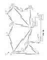
- tagscommunicate with the reader by backscattering the carrier signal, those tags very close to a reader create a very strong backscatter that can interfere with communications between other tags and readers located far away.
- tag-1generates so much backscatter that it can jam communications between tag-2 and Reader #2, even though both tag-2 and Reader #2 are located 200 meters away from tag-1.
- ais the extra distance necessary to provide a minimum “tag-2 to tag-1 signal to noise ratio” of at least 10 db (which is a typical minimum ratio that allows tag-2 to successfully communicate with Reader #1) [value can vary depending on system and environmental situation],
- d2is the distance between tag-2 and Reader #2
- d1is the distance between tag-1 and Reader #1.
- a Radio Frequency Identification (RFID) systemincludes a reader having a receive antenna in communication therewith, and a plurality of transmitters in communication with the reader and spatially separated from the reader.
- RFIDRadio Frequency Identification
- the receive antennamay be located in close proximity to the reader.
- none of the transmitters that are actively functioningare positioned in close proximity to the reader.
- a first portion of the transmitterstransmit in a first frequency simultaneously with a second portion of the transmitters transmitting in a second frequency.
- the first and second portions of the transmitterstransmit to RFID tags simultaneously.
- the first and second portions of the transmittershop frequencies at about a same time.
- the readermay be in communication with several transmitters, e.g., 10, 25, or more.
- the readermay communicate with the transmitters via wired or wireless connection.
- a transmission power of each of the transmittersis preferably less than about 100 milliwatts, and more preferably, continuously less than about 10 milliwatts.
- the transmittersmay or may not be able to receive a backscattered RF signal.
- Each of the transmittersmay be separately controllable.
- a methodenables locating RFID tags utilizing a system having a reader with a receive antenna coupled thereto and a plurality of transmitters in communication with the reader and spatially separated from the reader, including systems such as that described above.
- the methodincludes instructing at least one of the transmitters to transmit a signal, listening for a backscattered signal from a particular transponder, estimating a location of the particular transponder if a backscattered signal from the particular transponder is received, and instructing at least another of the transmitters to transmit a signal if no backscattered signal from the particular transponder is received.
- additional transmittersmay be instructed to transmit a signal if a backscattered signal from the particular transponder is received, upon which the reader listens for a backscattered signal from a particular transponder, where the backscattered signals are analyzed during estimating the location of the particular transponder.
- FIG. 1Ais a system diagram of an RFID system according to one embodiment of the present invention.
- FIG. 1Bis a system diagram of an RFID system according to one embodiment of the present invention.
- FIG. 2is a system diagram for an integrated circuit (IC) chip for implementation in an RFID tag.
- ICintegrated circuit
- FIG. 3is a process diagram of a method for locating an RFID tag according to one embodiment of the present invention.
- RFID tagsare quickly gaining popularity for use in the monitoring and tracking of an item.
- RFID technologyallows a user to remotely store and retrieve data in connection with an item utilizing a small, unobtrusive tag.
- an RFID tagoperates in the radio frequency (RF) portion of the electromagnetic spectrum, an electromagnetic or electrostatic coupling can occur between an RFID tag affixed to an item and an RFID tag reader. This coupling is advantageous, as it precludes the need for a direct contact or line of sight connection between the tag and the reader.
- RFradio frequency
- an itemmay be tagged at a period when the initial properties of the item are known. For example, this first tagging of the item may correspond with the beginning of the manufacturing process, or may occur as an item is first packaged for delivery. Electronically tagging the item allows for subsequent electronic exchanges of information between the tagged item and a user, wherein a user may read information stored within the tag and may additionally write information to the tag.
- an RFID system 100includes RFID tags 102 , an interrogator or “reader” 104 , and an optional server 106 or other backend system which may include databases containing information relating to RFID tags and/or tagged items.
- Each tag 102may be coupled to an object.
- Each tag 102includes a chip and an antenna. The chip includes a digital decoder needed to execute the computer commands that the tag 102 receives from the reader 104 .
- the chipmay also include a power supply circuit to extract and regulate power from the RF reader; a detector to decode signals from the reader; a backscatter modulator, a transmitter to send data back to the reader; anti-collision protocol circuits; and at least enough memory to store its unique identification code, e.g., Electronic Product Code (EPC).
- EPCElectronic Product Code
- the EPCis a simple, compact identifier that uniquely identities objects (items, cases, pallets, locations, etc.) in the supply chain.
- the EPCis built around a basic hierarchical idea that can be used to express a wide variety of different, existing numbering systems, like the EAN.UCC System Keys, UID, VIN, and other numbering systems.
- the EPCis divided into numbers that identify the manufacturer and product type.
- the EPCuses an extra set of digits, a serial number, to identify unique items.
- a typical EPC numbercontains:
- Each tag 102may also store information about the item to which coupled, including but not limited to a name or type of item, serial number of the item, date of manufacture, place of manufacture, owner identification, origin and/or destination information, expiration date, composition, information relating to or assigned by governmental agencies and regulations, etc.
- data relating to an itemcan be stored in one or more databases linked to the RFID tag. These databases do not reside on the tag, but rather are linked to the tag through a unique identifiers) or reference key(s).
- Communicationbegins with a reader 104 sending out signals via radio wave to find a tag 102 .
- the reader 104decodes the data programmed into the tag 102 .
- the informationis then passed to a server 106 for processing, storage, and/or propagation to another computing device.
- RFID systemsuse reflected or “backscattered” radio frequency (RF) waves to transmit information from the tag 102 to the reader 104 . Since passive (Class-1 and Class-2) tags get all of their power from the reader signal, the tags are only powered when in the beam of the reader 104 .
- RFradio frequency
- Semi-passive tagsalso called semi-active tags
- Active, semi-passive and passive RFID tagsmay operate within various regions of the radio frequency spectrum.
- Low-frequency (30 KHz to 500 KHz) tagshave low system costs and are limited to short reading ranges.
- Low frequency tagsmay be used in security access and animal identification applications for example.
- Ultra high-frequency (860 MHz to 960 MHz and 2.4 GHz to 2.5 GHz) tagsoffer increased read ranges and high reading speeds.
- One illustrative application of ultra high-frequency tagsis automated toll collection on highways and interstates.
- the reader 104has a receive antenna (Rx) 110 in communication therewith, and a plurality of transmitters (Tx) 112 in communication with the reader 104 .
- the receive antenna 110may or may not be located in close proximity to the reader, e.g., within about 2 feet, while the transmitters 112 are preferably spatially separated from the reader, e.g., greater than about 2 feet away.
- a benefit of having the transmitters 112 positioned far from the readeris that the reader receiving circuitry will have improved sensitivity because it is not co-located with the carrier wave transmitter.
- one of the transmitters 112could be in close proximity to the reader, while the rest of the transmitters are positioned farther away.
- An RFID systemis an RFID system with the reader transmitter decentralized, and the transmit function is implemented using distributed low power transmitters. The result is a system which illuminates the site with significantly less RF power than conventional systems and provides the ability to locate tags by proximity to one or more of the distributed transmitters.
- FIG. 1Billustrates an embodiment 100 in which none of the transmitters 112 that are actively functioning are positioned in close proximity to the reader 104 , while the receive antenna 110 is adjacent to the reader.
- RFID tags 102 to be identified and/or locatedare also present.
- An optional second reader 120is also shown. The second reader 120 may share duties with the first reader 104 , function autonomously, etc., and may or may not be in communication with some or all of the various transmitters 112 .
- the transmitters 112are preferably distributed close to where the tags 102 are located such that many if not all tags 102 have one of the transmitters 112 within a close proximity.
- a transmitter 112can be placed above each shelf or section in a large warehouse.
- the forward link from the reader 104operates by sending commands from the reader 104 to one or more selected transmitters 112 , which may include all transmitters 112 .
- the commands from the reader 104 to the transmitters 112may be protocol compliant, with the transmitters 112 merely broadcasting the command.
- the transmitters 112may convert commands from the reader 104 into protocol compliant commands readable by the tags 102 .
- the forward link from the transmitters 112 to the tags 102operates by sending protocol compliant commands from the distributed transmitters 112 to the tags 102 .
- Multiple transmittersmay operate simultaneously in an installation environment by using different frequencies.
- the frequency and/or sorting out tag responsescan be synchronized by the central reader.
- a first portion of the transmitterstransmit in a first frequency while a second portion of the transmitters transmit in a second frequency.
- a third set of transmitterstransmits in a third frequency
- a fourth settransmits in a fourth frequency, etc.
- each transmittermay transmit in a unique frequency.
- the first and second portions of the transmitterstransmit to RFID tags simultaneously, in the same or different frequencies.
- the first and second portions of the transmittersmay hop frequencies at about the same time.
- each of the transmitters, or groups thereofmay be separately controllable.
- the readermay transmit certain data to one or more selected transmitters instead of transmitting the data in all channels. For example, where the locations of the transmitters are known, only transmitters in a first geographical area may transmit a first string of data, while transmitters in a second geographical area transmit a second string of data. Such operations may be performed simultaneously. Also, the geographical areas may or may not overlap, and may be based on a known or expected location of a given tag.
- the transmitterspreferably transmit at low power.
- the RFID systemis able to operate with significantly lower radiated RF power because of the proximity of the distributed transmitters to the tags.
- the ability to operate with low power transmissionsprovides several advantages.
- One advantageis that the “hot tag” problem mentioned above is minimized.
- Another benefitis that propagation of the signal is minimized.
- a transmission power of each of the transmittersis preferably less than about 100 milliwatts, and more preferably, continuously less than about 10 milliwatts. Even at these low power levels, the inventor expects about a 30 dB improvement in Class-3 tag average response signals.
- the reverse linkpreferably operates on the principle of sending a continuous wave (CW) carrier from the transmitters to the tags, where the carrier is modulated by a tag backscatter operation.
- the data from the tagis transferred to the receive antenna of the reader via this scatter modulation.
- the tagstransmit directly to the reader.
- a configuration where the receive antenna is in close proximity to the readerprovides the benefits of low power transmissions and low cost as only one receive path may be required.
- the transmittersmay receive the backscattered signal, though such a system would be much more complex and require bidirectional links between the reader and transmitters.
- the readercommunicates with several transmitters, e.g., 10, 25, or more.
- the link between the reader and the transmitterscan be either wired or wireless. If wireless, the reader may have a transmitting antenna dedicated to transmitting solely to the transmitters, serving the dual function of transmitting to the transmitters and transmitting to tags, etc. Any suitable wireless protocol may be used, including RFID protocols, wireless networking protocols such as IEEE 802.11 (a/b/g), BLUETOOTH compliant protocols, etc. In a wired link configuration, unidirectional or bidirectional wires and any suitable communications protocol may be used.
- the systemis preferably operated in conjunction with battery assisted tags, which are able to reply to weak transmission signals. This allows the transmission power of each transmitter to be set to a very low level.
- the systemmay also be used with passive tags. With any of the embodiments described herein, there is no need to change the tag design to operate with the system.
- Embodiments of the present inventionare preferably implemented in a Class-3 or higher Class chip, which typically contains the control circuitry for most if not all tag operations.
- FIG. 2depicts a circuit layout of a Class-3 chip 200 and the various control circuitry according to an illustrative embodiment for implementation in an RFID tag.
- This Class-3 chipcan form the core of RFID chips appropriate for many applications such as identification of pallets, cartons, containers, vehicles, or anything where a range of more than 2-3 meters is desired.
- the chip 200includes several circuits including a power generation and regulation circuit 202 , a digital command decoder and control circuit 204 , a sensor interface module 206 , a C1G2 interface protocol circuit 208 , and a power source (battery) 210 .
- a display driver module 212can be added to drive a display.
- a battery activation circuit 214is also present to act as a wake-up trigger. In brief, many portions of the chip 200 remain in hibernate state during periods of inactivity. A hibernate state may mean a low power state, or a no power state. The battery activation circuit 214 remains active and processes incoming signals to determine whether any of the signals contain an activate command. If one signal does contain a valid activate command, additional portions of the chip 200 are wakened from the hibernate state, and communication with the reader can commence. In one embodiment, the battery activation circuit 214 includes an ultra-low-power, narrow-bandwidth preamplifier with an ultra low power static current drain.
- the battery activation circuit 214also includes a self-clocking interrupt circuit and uses an innovative user-programmable digital wake-up code.
- the battery activation circuit 214draws less power during its sleeping state and is much better protected against both accidental and malicious false wake-up trigger events that otherwise would lead to pre-mature exhaustion of the Class-3 tag battery 210 .
- a battery monitor 215can be provided to monitor power usage in the device. The information collected can then be used to estimate a useful remaining life of the battery.
- a forward link AM decoder 216uses a simplified phase-lock-loop oscillator that requires an absolute minimum amount of chip area. Preferably, the circuit 216 requires only a minimum string of reference pulses.
- a backscatter modulator block 218preferably increases the backscatter modulation depth to more than 50%.
- a memory celle.g., EEPROM
- EEPROMelectrically erasable programmable read-only memory
- a pure, Fowler-Nordheim direct-tunneling-through-oxide mechanism 220is present to reduce both the WRITE and ERASE currents to about 2 ⁇ A/cell in the EEPROM memory array. Unlike any RFID tags built to date, this will permit designing of tags to operate at maximum range even when WRITE and ERASE operations are being performed. In other embodiments, the WRITE and ERASE currents may be higher or lower, depending on the type of memory used and its requirements.
- the module 200may also incorporate a highly-simplified, yet very effective, security encryption circuit 222 .
- Other security schemes, secret handshakes with readers, etc.can be used.
- connection pads(not shown) are required for the illustrative chip 200 of FIG. 2 to function: Vdd to the battery, ground, plus two antenna leads to support multi-element omni-directional and isotropic antennas. Sensors to monitor temperature, shock, tampering, etc. can be added by appending an industry-standard I 2 C or SPI interface to the core chip.
- ASICsApplication Specific Integrated Circuits
- FPGAsField Programmable Gate Arrays
- the inventioncan also be provided in the form of a computer program product comprising a computer readable medium having computer code thereon.
- a computer readable mediumcan include any medium capable of storing computer code thereon for use by a computer, including optical media such as read only and writeable CD and DVD, magnetic memory, semiconductor memory (e.g., FLASH memory and other portable memory cards, etc.), etc.
- optical mediasuch as read only and writeable CD and DVD, magnetic memory, semiconductor memory (e.g., FLASH memory and other portable memory cards, etc.), etc.
- such softwarecan be downloadable or otherwise transferable from one computing device to another via network, wireless link, nonvolatile memory device, etc.
- FIG. 3illustrates a method 300 for locating an RFID tag utilizing a system having a reader with a receive antenna coupled thereto and a plurality of transmitters in communication with the reader and spatially separated from the reader, including systems such as those described above.
- at least one of the transmittersis instructed to transmit a signal.
- individual transmittersmay sequentially/semi-randomly transmit a signal, groups of transmitters may transmit a signal, and/or all transmitters may transmit a signal.
- the systemlistens for a backscattered signal from a particular transponder (e.g., RFID tag).
- the particular transpondercan be identified by its unique identification number or some other known characteristic.
- one or more transmittersmay be instructed to transmit a signal if a backscattered signal from the particular transponder is received, upon which the reader listens for a backscattered signal from a particular transponder.
- the backscattered signal(s)may then be analyzed during estimating the location of the particular transponder.
- a location of the particular transponderis estimated if a backscattered signal from the particular transponder is received.
- the location of the transpondercan be estimated in many ways. Relatively simple algorithms can be used to identify the location of the tags based on the location of the transmitters. For example, the system may use triangulation based on the strength of a signal backscattered by the tag from two or more transmitters. Less accurately, the system may identify which transmitter was able to operate the transponder.
- the transmittersare operating at low power, occasions might occur where no backscatter is received after a transmission from a particular transmitter or group of transmitters. In that case, in operation 310 , at least another of the transmitters is instructed to transmit a signal if no backscattered signal from the particular transponder is received.
Landscapes
- Engineering & Computer Science (AREA)
- Computer Networks & Wireless Communication (AREA)
- Signal Processing (AREA)
- Physics & Mathematics (AREA)
- Electromagnetism (AREA)
- Near-Field Transmission Systems (AREA)
Abstract
Description
D=a×b×(d2/d1) Equation 1
where:
- 1. Header, which identifies the length, type, structure, version and generation of EPC;
- 2. Manager Number, which identifies the company or company entity;
- 3. Object Class, similar to a stock keeping unit or SKU; and
- 4. Serial Number, which is the specific instance of the Object Class being tagged.
Additional fields may also be used as part of the EPC in order to properly encode and decode information from different numbering systems into their native (human-readable) forms.
Claims (41)
Priority Applications (2)
| Application Number | Priority Date | Filing Date | Title |
|---|---|---|---|
| US11/530,418US8570172B2 (en) | 2006-09-08 | 2006-09-08 | RFID system with distributed transmitters |
| PCT/US2007/019508WO2008030550A2 (en) | 2006-09-08 | 2007-09-07 | Rfid system with distributed transmitters |
Applications Claiming Priority (1)
| Application Number | Priority Date | Filing Date | Title |
|---|---|---|---|
| US11/530,418US8570172B2 (en) | 2006-09-08 | 2006-09-08 | RFID system with distributed transmitters |
Publications (2)
| Publication Number | Publication Date |
|---|---|
| US20080068174A1 US20080068174A1 (en) | 2008-03-20 |
| US8570172B2true US8570172B2 (en) | 2013-10-29 |
Family
ID=39165719
Family Applications (1)
| Application Number | Title | Priority Date | Filing Date |
|---|---|---|---|
| US11/530,418Expired - Fee RelatedUS8570172B2 (en) | 2006-09-08 | 2006-09-08 | RFID system with distributed transmitters |
Country Status (2)
| Country | Link |
|---|---|
| US (1) | US8570172B2 (en) |
| WO (1) | WO2008030550A2 (en) |
Cited By (8)
| Publication number | Priority date | Publication date | Assignee | Title |
|---|---|---|---|---|
| US20140292494A1 (en)* | 2007-03-23 | 2014-10-02 | Mojix, Inc. | RFID Systems Using Distributed Exciter Network |
| US9570420B2 (en) | 2011-09-29 | 2017-02-14 | Broadcom Corporation | Wireless communicating among vertically arranged integrated circuits (ICs) in a semiconductor package |
| US9747768B1 (en) | 2016-02-25 | 2017-08-29 | Xerox Corporation | System and method for proving physical presence |
| US9883337B2 (en) | 2015-04-24 | 2018-01-30 | Mijix, Inc. | Location based services for RFID and sensor networks |
| US10552652B2 (en)* | 2017-09-29 | 2020-02-04 | Omron Corporation | RFID system and information processing method |
| US10585159B2 (en) | 2008-04-14 | 2020-03-10 | Mojix, Inc. | Radio frequency identification tag location estimation and tracking system and method |
| US11265042B2 (en)* | 2017-12-07 | 2022-03-01 | Worldpay Limited | Wireless communication between electronic devices in close proximity |
| US20230231599A1 (en)* | 2022-01-14 | 2023-07-20 | Bae Systems Information And Electronic Systems Integration Inc. | Delay compensated analog beam forming network |
Families Citing this family (28)
| Publication number | Priority date | Publication date | Assignee | Title |
|---|---|---|---|---|
| JP2010504580A (en)* | 2006-09-22 | 2010-02-12 | コーニンクレッカ フィリップス エレクトロニクス エヌ ヴィ | RFID device expansion function |
| US8237546B2 (en)* | 2007-06-28 | 2012-08-07 | Symbol Technologies, Inc. | Backscatter limited tags |
| US8624710B2 (en)* | 2007-08-16 | 2014-01-07 | Farpointe Data, Inc. | System and method for interrogation radio-frequency identification |
| US8411764B2 (en)* | 2007-08-16 | 2013-04-02 | Farpointe Data, Inc. | System and method for multi-protocol radio-frequency identification |
| US8866599B2 (en)* | 2008-10-24 | 2014-10-21 | International Business Machines Corporation | Method of activating a supplemental visual warning signal based on frequency emitted from a generator of a primary audible warning signal |
| US8077041B2 (en)* | 2008-12-23 | 2011-12-13 | Symbol Technologies, Inc. | Real-time automatic RFID inventory control system |
| US8320856B2 (en)* | 2009-06-09 | 2012-11-27 | Broadcom Corporation | Method and system for a leaky wave antenna as a load on a power amplifier |
| US8588686B2 (en)* | 2009-06-09 | 2013-11-19 | Broadcom Corporation | Method and system for remote power distribution and networking for passive devices |
| US8508422B2 (en)* | 2009-06-09 | 2013-08-13 | Broadcom Corporation | Method and system for converting RF power to DC power utilizing a leaky wave antenna |
| US8295788B2 (en) | 2009-06-09 | 2012-10-23 | Broadcom Corporation | Method and system for an N-phase transmitter utilizing a leaky wave antenna |
| US20110037572A1 (en)* | 2009-08-13 | 2011-02-17 | Identec Solutions Ag | Method for the operation of a transponder for radio frequency identification (rfid) and rfid transponder |
| US20120280797A1 (en)* | 2010-11-08 | 2012-11-08 | System Planning Corporation | System And Apparatus For Item Level Inventory Management Within A Virtual Warehouse Established For Short-Term And Long-Term Disaster Relief Operations |
| US20130088354A1 (en)* | 2011-10-07 | 2013-04-11 | Jackson Thomas | System, Method and Device for Tracking Surgical Sponges |
| EP2642423B1 (en)* | 2012-03-22 | 2015-06-10 | Nxp B.V. | Combined multifunctional RFID communication device |
| US10474852B2 (en)* | 2014-10-31 | 2019-11-12 | Teslonix Inc. | Charging long-range radio frequency identification tags |
| EP3213390A4 (en) | 2014-10-31 | 2018-03-14 | Teslonix Inc. | Wireless energy transfer using alignment of electromagnetic waves |
| US10530190B2 (en) | 2014-10-31 | 2020-01-07 | Teslonix Inc. | Wireless energy transfer in a multipath environment |
| US10079616B2 (en) | 2014-12-19 | 2018-09-18 | University Of Washington | Devices and methods for backscatter communication using one or more wireless communication protocols including bluetooth low energy examples |
| WO2017027847A1 (en)* | 2015-08-12 | 2017-02-16 | University Of Washington | Backscatter devices and network systems incorporating backscatter devices |
| CN108496094B (en) | 2016-01-26 | 2023-04-28 | 华盛顿大学 | Backscattering device incorporating an instance of single sideband operation |
| US11829927B2 (en) | 2016-05-04 | 2023-11-28 | United Parcel Service Of America, Inc. | Remote initiation of interaction by a computing entity |
| US9905100B2 (en)* | 2016-05-04 | 2018-02-27 | United Parcel Service Of America, Inc. | Remote initiation of interaction by a computing entity |
| CN106234230A (en)* | 2016-10-08 | 2016-12-21 | 佛山迁宇科技有限公司 | A kind of tissue culture flasks based on NFC technique |
| WO2018075653A1 (en) | 2016-10-18 | 2018-04-26 | University Of Washington | Backscatter systems, devices, and techniques utilizing css modulation and/or higher order harmonic cancellation |
| EP3607429A4 (en) | 2017-04-06 | 2021-01-06 | The University of Washington | Image and/or video transmission using backscatter devices |
| US11276025B2 (en) | 2017-10-24 | 2022-03-15 | United Parcel Service Of America, Inc. | Automated occupant tracking systems and methods |
| US10796112B2 (en) | 2018-05-28 | 2020-10-06 | Teslonix Inc. | Protocol layer coordination of wireless energy transfer systems |
| US20240346268A1 (en)* | 2023-04-13 | 2024-10-17 | Bruce Walter Wilkinson | Session Control Broadcaster for RFID Systems |
Citations (30)
| Publication number | Priority date | Publication date | Assignee | Title |
|---|---|---|---|---|
| US20010040513A1 (en)* | 1999-05-24 | 2001-11-15 | Mcdonald Glenn | Method and apparatus for tracking and locating a moveable article |
| US6333703B1 (en)* | 1998-11-24 | 2001-12-25 | International Business Machines Corporation | Automated traffic mapping using sampling and analysis |
| US20020055345A1 (en)* | 1996-12-18 | 2002-05-09 | Wood Clifton W. | Wireless communication system, radio frequency communications system, wireless communications method, radio frequency communications method, and backscatter radio frequency communications system |
| US20020126013A1 (en) | 2001-03-08 | 2002-09-12 | Symbol Technologies, Inc. | Hybrid Bluetooth/RFID based real time location tracking |
| US20020149483A1 (en)* | 2001-02-12 | 2002-10-17 | Matrics, Inc. | Method, System, and apparatus for communicating with a RFID tag population |
| US20020181565A1 (en) | 2001-05-04 | 2002-12-05 | Wherenet Corp | Real-time locating system and method using timing signal |
| US20020196126A1 (en)* | 2001-06-05 | 2002-12-26 | 3M Innovative Properties Company | Raido frequency identification in document management |
| US6657586B2 (en) | 2001-05-03 | 2003-12-02 | Wherenet Corp | System and method for locating an object using global positioning system receiver |
| US20040150521A1 (en) | 2003-02-03 | 2004-08-05 | Stilp Louis A. | RFID based security system |
| US20040153207A1 (en) | 2003-01-30 | 2004-08-05 | Peck John C. | Distributed intelligence, wireless, light-directed pick/put system |
| US6853294B1 (en) | 2000-07-26 | 2005-02-08 | Intermec Ip Corp. | Networking applications for automated data collection |
| US20050040934A1 (en) | 2003-08-22 | 2005-02-24 | Kenneth Shanton | Point-of-purchase display with RFID inventory control |
| US20050110641A1 (en) | 2002-03-18 | 2005-05-26 | Greg Mendolia | RFID tag reading system and method |
| US20050193149A1 (en) | 2003-11-07 | 2005-09-01 | Wherenet Corp., Corporation Of The State Of California | Location system and method that achieves time synchronized network performance with nodes divided into separate networks |
| US20060145842A1 (en)* | 2003-02-03 | 2006-07-06 | Stilp Louis A | Multi-level meshed security network |
| US20070159338A1 (en)* | 2005-12-22 | 2007-07-12 | Axcess International Inc. | Hybrid Radio Frequency Identification (RFID) Tag System |
| US20070206705A1 (en)* | 2006-03-03 | 2007-09-06 | Applied Wireless Identification Group, Inc. | RFID reader with adjustable filtering and adaptive backscatter processing |
| US7284703B2 (en)* | 2002-10-18 | 2007-10-23 | Symbol Technologies, Inc. | System and method for minimizing unwanted re-negotiation of a passive RFID tag |
| US20070257795A1 (en)* | 2006-05-04 | 2007-11-08 | Goliath Solutions, Llc | Systems and methods for approximating the location of an RFID tag |
| US20080042838A1 (en)* | 2006-08-14 | 2008-02-21 | Eduard Levin | Identification and location of RF tagged articles |
| US7408463B2 (en)* | 2005-09-30 | 2008-08-05 | Intel Corporation | Radio frequency identification tag |
| US20080186180A1 (en)* | 2005-12-09 | 2008-08-07 | Butler Timothy P | Methods and systems of a multiple radio frequency network node rfid tag |
| US7413124B2 (en)* | 2005-07-19 | 2008-08-19 | 3M Innovative Properties Company | RFID reader supporting one-touch search functionality |
| US7616113B2 (en)* | 2007-01-04 | 2009-11-10 | International Business Machines Corporation | Spatially locating RFID tags using multiple readers and correction factors |
| US7619529B2 (en)* | 1998-08-14 | 2009-11-17 | 3M Innovative Properties Company | Application for a radio frequency identification system |
| US20100060432A1 (en)* | 2008-09-05 | 2010-03-11 | Johannes Albertus Van Niekerk | Battery Assisted Tag and RFID System |
| US7701340B2 (en)* | 2003-04-17 | 2010-04-20 | Alcea | Method and device for the detection and identification of objects, secure containers and systems which are provided with said device, and objects adapted for same |
| US7760074B2 (en)* | 2007-01-29 | 2010-07-20 | International Business Machines Corporation | Diagnosing a radio frequency identification reader |
| US7834765B2 (en)* | 2002-07-09 | 2010-11-16 | Automated Tracking Solutions, Llc | Method and apparatus for tracking objects and people |
| US8125316B2 (en)* | 1999-08-09 | 2012-02-28 | Round Rock Research, Llc | RFID material tracking method and apparatus |
- 2006
- 2006-09-08USUS11/530,418patent/US8570172B2/ennot_activeExpired - Fee Related
- 2007
- 2007-09-07WOPCT/US2007/019508patent/WO2008030550A2/enactiveApplication Filing
Patent Citations (35)
| Publication number | Priority date | Publication date | Assignee | Title |
|---|---|---|---|---|
| US20020055345A1 (en)* | 1996-12-18 | 2002-05-09 | Wood Clifton W. | Wireless communication system, radio frequency communications system, wireless communications method, radio frequency communications method, and backscatter radio frequency communications system |
| US7619529B2 (en)* | 1998-08-14 | 2009-11-17 | 3M Innovative Properties Company | Application for a radio frequency identification system |
| US6333703B1 (en)* | 1998-11-24 | 2001-12-25 | International Business Machines Corporation | Automated traffic mapping using sampling and analysis |
| US20010040513A1 (en)* | 1999-05-24 | 2001-11-15 | Mcdonald Glenn | Method and apparatus for tracking and locating a moveable article |
| US8125316B2 (en)* | 1999-08-09 | 2012-02-28 | Round Rock Research, Llc | RFID material tracking method and apparatus |
| US20050104719A1 (en) | 2000-07-26 | 2005-05-19 | Shashi Ramamurthy | Networking applications for automated data collection |
| US6853294B1 (en) | 2000-07-26 | 2005-02-08 | Intermec Ip Corp. | Networking applications for automated data collection |
| US20020149483A1 (en)* | 2001-02-12 | 2002-10-17 | Matrics, Inc. | Method, System, and apparatus for communicating with a RFID tag population |
| US20020126013A1 (en) | 2001-03-08 | 2002-09-12 | Symbol Technologies, Inc. | Hybrid Bluetooth/RFID based real time location tracking |
| US6717516B2 (en) | 2001-03-08 | 2004-04-06 | Symbol Technologies, Inc. | Hybrid bluetooth/RFID based real time location tracking |
| US6657586B2 (en) | 2001-05-03 | 2003-12-02 | Wherenet Corp | System and method for locating an object using global positioning system receiver |
| US20020181565A1 (en) | 2001-05-04 | 2002-12-05 | Wherenet Corp | Real-time locating system and method using timing signal |
| US20020196126A1 (en)* | 2001-06-05 | 2002-12-26 | 3M Innovative Properties Company | Raido frequency identification in document management |
| US20050110641A1 (en) | 2002-03-18 | 2005-05-26 | Greg Mendolia | RFID tag reading system and method |
| US7834765B2 (en)* | 2002-07-09 | 2010-11-16 | Automated Tracking Solutions, Llc | Method and apparatus for tracking objects and people |
| US7284703B2 (en)* | 2002-10-18 | 2007-10-23 | Symbol Technologies, Inc. | System and method for minimizing unwanted re-negotiation of a passive RFID tag |
| US6775588B1 (en) | 2003-01-30 | 2004-08-10 | Foxfire Technologies, Inc. | Distributed intelligence, wireless, light-directed pick/put system |
| US20040153207A1 (en) | 2003-01-30 | 2004-08-05 | Peck John C. | Distributed intelligence, wireless, light-directed pick/put system |
| US20060145842A1 (en)* | 2003-02-03 | 2006-07-06 | Stilp Louis A | Multi-level meshed security network |
| US20040150521A1 (en) | 2003-02-03 | 2004-08-05 | Stilp Louis A. | RFID based security system |
| US6888459B2 (en) | 2003-02-03 | 2005-05-03 | Louis A. Stilp | RFID based security system |
| US7701340B2 (en)* | 2003-04-17 | 2010-04-20 | Alcea | Method and device for the detection and identification of objects, secure containers and systems which are provided with said device, and objects adapted for same |
| US20050040934A1 (en) | 2003-08-22 | 2005-02-24 | Kenneth Shanton | Point-of-purchase display with RFID inventory control |
| US20050193149A1 (en) | 2003-11-07 | 2005-09-01 | Wherenet Corp., Corporation Of The State Of California | Location system and method that achieves time synchronized network performance with nodes divided into separate networks |
| US7413124B2 (en)* | 2005-07-19 | 2008-08-19 | 3M Innovative Properties Company | RFID reader supporting one-touch search functionality |
| US7408463B2 (en)* | 2005-09-30 | 2008-08-05 | Intel Corporation | Radio frequency identification tag |
| US20080186180A1 (en)* | 2005-12-09 | 2008-08-07 | Butler Timothy P | Methods and systems of a multiple radio frequency network node rfid tag |
| US20070159338A1 (en)* | 2005-12-22 | 2007-07-12 | Axcess International Inc. | Hybrid Radio Frequency Identification (RFID) Tag System |
| US20070206705A1 (en)* | 2006-03-03 | 2007-09-06 | Applied Wireless Identification Group, Inc. | RFID reader with adjustable filtering and adaptive backscatter processing |
| US7423516B2 (en)* | 2006-05-04 | 2008-09-09 | Goliath Solutions, Llc | Systems and methods for approximating the location of an RFID tag |
| US20070257795A1 (en)* | 2006-05-04 | 2007-11-08 | Goliath Solutions, Llc | Systems and methods for approximating the location of an RFID tag |
| US20080042838A1 (en)* | 2006-08-14 | 2008-02-21 | Eduard Levin | Identification and location of RF tagged articles |
| US7616113B2 (en)* | 2007-01-04 | 2009-11-10 | International Business Machines Corporation | Spatially locating RFID tags using multiple readers and correction factors |
| US7760074B2 (en)* | 2007-01-29 | 2010-07-20 | International Business Machines Corporation | Diagnosing a radio frequency identification reader |
| US20100060432A1 (en)* | 2008-09-05 | 2010-03-11 | Johannes Albertus Van Niekerk | Battery Assisted Tag and RFID System |
Non-Patent Citations (2)
| Title |
|---|
| International Search Report and Written Opinion from PCT Application No. PCT/US07/19508 mailed on Mar. 31, 2008. |
| The International Preliminary Report on Patentability from PCT Application No. PCT/US2007/019508 mailed on Mar. 19, 2009. |
Cited By (20)
| Publication number | Priority date | Publication date | Assignee | Title |
|---|---|---|---|---|
| US20140292494A1 (en)* | 2007-03-23 | 2014-10-02 | Mojix, Inc. | RFID Systems Using Distributed Exciter Network |
| US9690957B2 (en)* | 2007-03-23 | 2017-06-27 | Mojix, Inc. | RFID systems using distributed exciter network |
| US10585159B2 (en) | 2008-04-14 | 2020-03-10 | Mojix, Inc. | Radio frequency identification tag location estimation and tracking system and method |
| US9570420B2 (en) | 2011-09-29 | 2017-02-14 | Broadcom Corporation | Wireless communicating among vertically arranged integrated circuits (ICs) in a semiconductor package |
| US9883337B2 (en) | 2015-04-24 | 2018-01-30 | Mijix, Inc. | Location based services for RFID and sensor networks |
| US9747768B1 (en) | 2016-02-25 | 2017-08-29 | Xerox Corporation | System and method for proving physical presence |
| US10552652B2 (en)* | 2017-09-29 | 2020-02-04 | Omron Corporation | RFID system and information processing method |
| US11539402B2 (en)* | 2017-12-07 | 2022-12-27 | Worldpay Limited | Wireless communication between electronic devices in close proximity |
| US20220123787A1 (en)* | 2017-12-07 | 2022-04-21 | Worldpay Limited | Wireless communication between electronic devices in close proximity |
| US20220271799A1 (en)* | 2017-12-07 | 2022-08-25 | Worldpay Limited | Wireless communication between electronic devices in close proximity |
| US11265042B2 (en)* | 2017-12-07 | 2022-03-01 | Worldpay Limited | Wireless communication between electronic devices in close proximity |
| US11616534B2 (en)* | 2017-12-07 | 2023-03-28 | Worldpay Limited | Wireless communication between electronic devices in close proximity |
| US11757493B2 (en)* | 2017-12-07 | 2023-09-12 | Worldpay Limited | Wireless communication between electronic devices in close proximity |
| US11770158B2 (en)* | 2017-12-07 | 2023-09-26 | Worldpay Limited | Wireless communication between electronic devices in close proximity |
| US20230327712A1 (en)* | 2017-12-07 | 2023-10-12 | Worldpay Limited | Wireless communication between electronic devices in close proximity |
| US20230370118A1 (en)* | 2017-12-07 | 2023-11-16 | Worldpay Limited | Wireless communication between electronic devices in close proximity |
| US12143171B2 (en)* | 2017-12-07 | 2024-11-12 | Worldpay Limited | Wireless communication between electronic devices in close proximity |
| US12206466B2 (en)* | 2017-12-07 | 2025-01-21 | Worldpay Limited | Wireless communication between electronic devices in close proximity |
| US20230231599A1 (en)* | 2022-01-14 | 2023-07-20 | Bae Systems Information And Electronic Systems Integration Inc. | Delay compensated analog beam forming network |
| US11901977B2 (en)* | 2022-01-14 | 2024-02-13 | Bae Systems Information And Electronic Systems Integration Inc. | Delay compensated analog beam forming network |
Also Published As
| Publication number | Publication date |
|---|---|
| WO2008030550A3 (en) | 2008-06-12 |
| US20080068174A1 (en) | 2008-03-20 |
| WO2008030550A2 (en) | 2008-03-13 |
Similar Documents
| Publication | Publication Date | Title |
|---|---|---|
| US8570172B2 (en) | RFID system with distributed transmitters | |
| US7525434B2 (en) | RF systems and methods for tracking and singulating tagged items | |
| US9087226B2 (en) | System, method and computer program product for calibrating interrogator signal strength and/or tag response range setting | |
| US8098159B2 (en) | RF device comparing DAC output to incoming signal for selectively performing an action | |
| US7321290B2 (en) | Radio tag and system | |
| US7561107B2 (en) | RFID device with microstrip antennas | |
| US8026819B2 (en) | Radio tag and system | |
| EP1904948B1 (en) | Ramped interrogation power levels | |
| US7791453B2 (en) | System and method for varying response amplitude of radio transponders | |
| US6738025B2 (en) | Antenna matching circuit | |
| US20040066281A1 (en) | System and method to identify multiple RFID tags | |
| US20070290791A1 (en) | Rfid-based security systems and methods | |
| US7215249B2 (en) | Radio frequency identification reader | |
| US8952790B2 (en) | Strong passive ad-hoc radio-frequency identification | |
| US20110163882A1 (en) | Passive Low Frequency Inductive Tagging | |
| US8717144B2 (en) | RFID system with distributed readers | |
| US20080062046A1 (en) | Mounting structure for matching an rf integrated circuit with an antenna and rfid device implementing same | |
| HK1167733A1 (en) | Rfid portal system with rfid tags having various read ranges | |
| HK1167733B (en) | Rfid portal system with rfid tags having various read ranges |
Legal Events
| Date | Code | Title | Description |
|---|---|---|---|
| AS | Assignment | Owner name:INTELLEFLEX CORPORATION, CALIFORNIA Free format text:ASSIGNMENT OF ASSIGNORS INTEREST;ASSIGNOR:AL-MAHDAWI, TAREEF IBRAHIM;REEL/FRAME:018429/0565 Effective date:20060906 | |
| AS | Assignment | Owner name:VENTURE LENDING & LEASING IV, INC. AS AGENT, CALIF Free format text:SECURITY INTEREST;ASSIGNOR:INTELLEFLEX CORPORATION;REEL/FRAME:020955/0628 Effective date:20080422 Owner name:VENTURE LENDING & LEASING IV, INC. AS AGENT,CALIFO Free format text:SECURITY INTEREST;ASSIGNOR:INTELLEFLEX CORPORATION;REEL/FRAME:020955/0628 Effective date:20080422 | |
| AS | Assignment | Owner name:VENTURE LENDING & LEASING V, INC., AS AGENT, CALIF Free format text:SECURITY AGREEMENT;ASSIGNOR:INTELLEFLEX CORPORATION;REEL/FRAME:020960/0279 Effective date:20080422 Owner name:VENTURE LENDING & LEASING V, INC., AS AGENT,CALIFO Free format text:SECURITY AGREEMENT;ASSIGNOR:INTELLEFLEX CORPORATION;REEL/FRAME:020960/0279 Effective date:20080422 | |
| STCF | Information on status: patent grant | Free format text:PATENTED CASE | |
| CC | Certificate of correction | ||
| AS | Assignment | Owner name:ZEST LABS, INC., CALIFORNIA Free format text:CHANGE OF NAME;ASSIGNOR:INTELLEFLEX CORPORATION;REEL/FRAME:041678/0799 Effective date:20161027 | |
| FPAY | Fee payment | Year of fee payment:4 | |
| FEPP | Fee payment procedure | Free format text:MAINTENANCE FEE REMINDER MAILED (ORIGINAL EVENT CODE: REM.); ENTITY STATUS OF PATENT OWNER: LARGE ENTITY | |
| LAPS | Lapse for failure to pay maintenance fees | Free format text:PATENT EXPIRED FOR FAILURE TO PAY MAINTENANCE FEES (ORIGINAL EVENT CODE: EXP.); ENTITY STATUS OF PATENT OWNER: LARGE ENTITY | |
| STCH | Information on status: patent discontinuation | Free format text:PATENT EXPIRED DUE TO NONPAYMENT OF MAINTENANCE FEES UNDER 37 CFR 1.362 | |
| FP | Lapsed due to failure to pay maintenance fee | Effective date:20211029 |