US8569142B2 - Multi-level thin film capacitor on a ceramic substrate and method of manufacturing the same - Google Patents
Multi-level thin film capacitor on a ceramic substrate and method of manufacturing the sameDownload PDFInfo
- Publication number
- US8569142B2 US8569142B2US11/736,408US73640807AUS8569142B2US 8569142 B2US8569142 B2US 8569142B2US 73640807 AUS73640807 AUS 73640807AUS 8569142 B2US8569142 B2US 8569142B2
- Authority
- US
- United States
- Prior art keywords
- capacitor
- layer
- thin film
- buffer layer
- layers
- Prior art date
- Legal status (The legal status is an assumption and is not a legal conclusion. Google has not performed a legal analysis and makes no representation as to the accuracy of the status listed.)
- Active, expires
Links
Images


Classifications
- H—ELECTRICITY
- H01—ELECTRIC ELEMENTS
- H01G—CAPACITORS; CAPACITORS, RECTIFIERS, DETECTORS, SWITCHING DEVICES, LIGHT-SENSITIVE OR TEMPERATURE-SENSITIVE DEVICES OF THE ELECTROLYTIC TYPE
- H01G4/00—Fixed capacitors; Processes of their manufacture
- H01G4/33—Thin- or thick-film capacitors (thin- or thick-film circuits; capacitors without a potential-jump or surface barrier specially adapted for integrated circuits, details thereof, multistep manufacturing processes therefor)
- H—ELECTRICITY
- H01—ELECTRIC ELEMENTS
- H01G—CAPACITORS; CAPACITORS, RECTIFIERS, DETECTORS, SWITCHING DEVICES, LIGHT-SENSITIVE OR TEMPERATURE-SENSITIVE DEVICES OF THE ELECTROLYTIC TYPE
- H01G4/00—Fixed capacitors; Processes of their manufacture
- H01G4/38—Multiple capacitors, i.e. structural combinations of fixed capacitors
- H—ELECTRICITY
- H01—ELECTRIC ELEMENTS
- H01G—CAPACITORS; CAPACITORS, RECTIFIERS, DETECTORS, SWITCHING DEVICES, LIGHT-SENSITIVE OR TEMPERATURE-SENSITIVE DEVICES OF THE ELECTROLYTIC TYPE
- H01G13/00—Apparatus specially adapted for manufacturing capacitors; Processes specially adapted for manufacturing capacitors not provided for in groups H01G4/00 - H01G11/00
- H01G13/04—Drying; Impregnating
- H—ELECTRICITY
- H05—ELECTRIC TECHNIQUES NOT OTHERWISE PROVIDED FOR
- H05K—PRINTED CIRCUITS; CASINGS OR CONSTRUCTIONAL DETAILS OF ELECTRIC APPARATUS; MANUFACTURE OF ASSEMBLAGES OF ELECTRICAL COMPONENTS
- H05K1/00—Printed circuits
- H05K1/16—Printed circuits incorporating printed electric components, e.g. printed resistor, capacitor, inductor
- H05K1/162—Printed circuits incorporating printed electric components, e.g. printed resistor, capacitor, inductor incorporating printed capacitors
- H—ELECTRICITY
- H10—SEMICONDUCTOR DEVICES; ELECTRIC SOLID-STATE DEVICES NOT OTHERWISE PROVIDED FOR
- H10D—INORGANIC ELECTRIC SEMICONDUCTOR DEVICES
- H10D86/00—Integrated devices formed in or on insulating or conducting substrates, e.g. formed in silicon-on-insulator [SOI] substrates or on stainless steel or glass substrates
- H10D86/80—Integrated devices formed in or on insulating or conducting substrates, e.g. formed in silicon-on-insulator [SOI] substrates or on stainless steel or glass substrates characterised by multiple passive components, e.g. resistors, capacitors or inductors
- H10D86/85—Integrated devices formed in or on insulating or conducting substrates, e.g. formed in silicon-on-insulator [SOI] substrates or on stainless steel or glass substrates characterised by multiple passive components, e.g. resistors, capacitors or inductors characterised by only passive components
- H—ELECTRICITY
- H05—ELECTRIC TECHNIQUES NOT OTHERWISE PROVIDED FOR
- H05K—PRINTED CIRCUITS; CASINGS OR CONSTRUCTIONAL DETAILS OF ELECTRIC APPARATUS; MANUFACTURE OF ASSEMBLAGES OF ELECTRICAL COMPONENTS
- H05K1/00—Printed circuits
- H05K1/02—Details
- H05K1/03—Use of materials for the substrate
- H05K1/0306—Inorganic insulating substrates, e.g. ceramic, glass
- H—ELECTRICITY
- H05—ELECTRIC TECHNIQUES NOT OTHERWISE PROVIDED FOR
- H05K—PRINTED CIRCUITS; CASINGS OR CONSTRUCTIONAL DETAILS OF ELECTRIC APPARATUS; MANUFACTURE OF ASSEMBLAGES OF ELECTRICAL COMPONENTS
- H05K2201/00—Indexing scheme relating to printed circuits covered by H05K1/00
- H05K2201/01—Dielectrics
- H05K2201/0137—Materials
- H05K2201/0175—Inorganic, non-metallic layer, e.g. resist or dielectric for printed capacitor
- H—ELECTRICITY
- H05—ELECTRIC TECHNIQUES NOT OTHERWISE PROVIDED FOR
- H05K—PRINTED CIRCUITS; CASINGS OR CONSTRUCTIONAL DETAILS OF ELECTRIC APPARATUS; MANUFACTURE OF ASSEMBLAGES OF ELECTRICAL COMPONENTS
- H05K2201/00—Indexing scheme relating to printed circuits covered by H05K1/00
- H05K2201/01—Dielectrics
- H05K2201/0137—Materials
- H05K2201/0179—Thin film deposited insulating layer, e.g. inorganic layer for printed capacitor
- H—ELECTRICITY
- H05—ELECTRIC TECHNIQUES NOT OTHERWISE PROVIDED FOR
- H05K—PRINTED CIRCUITS; CASINGS OR CONSTRUCTIONAL DETAILS OF ELECTRIC APPARATUS; MANUFACTURE OF ASSEMBLAGES OF ELECTRICAL COMPONENTS
- H05K3/00—Apparatus or processes for manufacturing printed circuits
- H05K3/38—Improvement of the adhesion between the insulating substrate and the metal
- H05K3/388—Improvement of the adhesion between the insulating substrate and the metal by the use of a metallic or inorganic thin film adhesion layer
- Y—GENERAL TAGGING OF NEW TECHNOLOGICAL DEVELOPMENTS; GENERAL TAGGING OF CROSS-SECTIONAL TECHNOLOGIES SPANNING OVER SEVERAL SECTIONS OF THE IPC; TECHNICAL SUBJECTS COVERED BY FORMER USPC CROSS-REFERENCE ART COLLECTIONS [XRACs] AND DIGESTS
- Y10—TECHNICAL SUBJECTS COVERED BY FORMER USPC
- Y10T—TECHNICAL SUBJECTS COVERED BY FORMER US CLASSIFICATION
- Y10T29/00—Metal working
- Y10T29/49—Method of mechanical manufacture
- Y10T29/49002—Electrical device making
- Y10T29/49117—Conductor or circuit manufacturing
- Y10T29/49124—On flat or curved insulated base, e.g., printed circuit, etc.
- Y10T29/49126—Assembling bases
- Y—GENERAL TAGGING OF NEW TECHNOLOGICAL DEVELOPMENTS; GENERAL TAGGING OF CROSS-SECTIONAL TECHNOLOGIES SPANNING OVER SEVERAL SECTIONS OF THE IPC; TECHNICAL SUBJECTS COVERED BY FORMER USPC CROSS-REFERENCE ART COLLECTIONS [XRACs] AND DIGESTS
- Y10—TECHNICAL SUBJECTS COVERED BY FORMER USPC
- Y10T—TECHNICAL SUBJECTS COVERED BY FORMER US CLASSIFICATION
- Y10T29/00—Metal working
- Y10T29/49—Method of mechanical manufacture
- Y10T29/49002—Electrical device making
- Y10T29/49117—Conductor or circuit manufacturing
- Y10T29/49124—On flat or curved insulated base, e.g., printed circuit, etc.
- Y10T29/49155—Manufacturing circuit on or in base
Definitions
- the technology described in this patent documentrelates generally to the field of thin film devices and fabrication. More particularly, the patent document describes a multi-level thin-film capacitor fabricated on a ceramic substrate and a method of manufacturing the same.
- Thin film circuit packagesare commonly used in space-constrained applications, such as hearing instrument products.
- a multi-level thin film capacitor on a ceramic substrate and method of manufacturing the sameare provided.
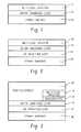
- FIG. 1is a diagram of an example multi-level thin film capacitor fabricated on a ceramic substrate.
- FIG. 2is a diagram of an example multi-level thin film capacitor fabricated on a ceramic substrate including a high density interconnect (HDI) layer.
- HDIhigh density interconnect
- FIG. 3is a diagram of an example multi-level thin film capacitor fabricated on a ceramic substrate and integrated with a thin film circuit.
- FIG. 4is a diagram of an example capacitor network integrating a thin film circuit including a high density multi-level thin film capacitor and a low density capacitor on a ceramic substrate with a high density thick film interconnect.
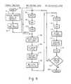
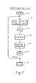
- FIGS. 5-9illustrate example processes for fabricating the circuit structure of FIG. 4 .
- FIG. 1is a diagram of an example multi-level thin film capacitor 14 fabricated on a ceramic substrate 10 . Also illustrated in FIG. 1 is a buffer (smoothing) layer 12 fabricated between the ceramic substrate 10 and the multi-level capacitor (MLC) 14 .
- a thin film MLCincludes one or more layers of high permittivity dielectric material (e.g., compounds containing Barium Strontium Titanium Oxide (Ba, Sr)TiO3, (BST)) deposited between electrode layers formed from a conductive thin film material (e.g., Pt, conductive oxides like, SrRuO3, LaNiO3, LaMn 1-x Co x O3, etc., other metals, like Au, Cu, W, etc.).
- a conductive thin film materiale.g., Pt, conductive oxides like, SrRuO3, LaNiO3, LaMn 1-x Co x O3, etc., other metals, like Au, Cu, W, etc.
- the MLC 14can be fabricated with a variety of capacitance-voltage characteristics depending on the material properties and processing conditions of the whole stack.
- the MLC 14may include a voltage variable (tunable) capacitor(s) and/or a fixed value capacitor(s), depending on the type of dielectric material used for the dielectric layer(s).
- the MLC 14may be a mesa-structure formed using photolithography patterning techniques (see, e.g., FIG. 4 ).
- the fabrication of a high value thin film capacitore.g., with an overall capacitance density from 10 to 390 fF/um 2
- a smooth surface sufficient for fabricating the MLC 14is provided by the buffer layer 12 .
- the buffer layer 12is a dielectric material that electrically isolates the thin film capacitor 14 and provides a smooth surface which is suitable for fabricating a thin film MLC 14 .
- the buffer layer 12may be a thick film dielectric material that is polished to provide a smooth upper surface (see, e.g., FIG. 7 ).
- the buffer layer 12may be a smooth (fire polished) glass dielectric material (see, e.g., FIG. 8 ).
- the surface roughness (Ra) of the smooth upper surfacemay be less than or equal to 0.08 micrometers (um), but is preferably less than or equal to 0.06 um.
- the surface roughness (Ra) of the smooth upper surfacemay be less than or equal to 0.08 um, but is preferably less than or equal to 0.03 um.
- the buffer layer 12is substantially free of micropores and is thus stable at high temperatures.
- the buffer layer 12may be able to withstand multiple anneals at high temperatures (e.g., 600-800° C.) in an oxidizing atmosphere without substantially affecting its surface quality or the resistivity of any metal filled vias.
- the high-k ferroelectric layer(s) of the MLC 14may be deposited using a simple spin-coat technology, as well as methods such as Physical Vapor Deposition (PVD) or Chemical Vapor Deposition (CVD).
- the ceramic substrate 10may, for example, be Al 2 O 3 , AlN, MgTiO 3 , Mg 2 SiO 4 or some other ceramic substrate material. Ceramic substrate materials are typically inexpensive and are highly machinable. The ceramic substrate 10 may therefore include fine-pitched metal filled through holes that provide low and controlled parasitics (see, e.g., FIG. 4 ). In addition, a ceramic substrate material provides substantially better Q-factors for other passive components (e.g. thin film inductors) than conventional silicon-based substrates.
- FIG. 2is a diagram of an example multi-level thin film capacitor 26 fabricated on a ceramic substrate 20 including a HDI layer 22 .
- the HDI layer 22is fabricated on the ceramic substrate using thick film materials and photolithography patterning techniques to create one or more layers of high density routing (i.e., metallic traces) and filled through holes (vias).
- the HDI layer 22may include buried resistors and/or capacitors.
- the HDI layer 24may, for example, be used to provide substrate level interconnect and electrical connections from the top to the bottom side of the substrate.
- the use of a low cost and high density thick film based interconnect layeris enabled by the use of a ceramic substrate material.
- FIG. 3is a diagram of an example multi-level thin film capacitor 36 fabricated on a ceramic substrate 30 and integrated with a thin film circuit 38 .
- the MLC 36may be interconnected in a thin film circuit 38 with other passive thin film circuit elements, such as decoupling capacitors, inductors, resistors, etc.
- an adhesion layer 34between the buffer layer 32 and the MLC 36 .
- the adhesion layer 34may be included to adhere the bottom electrode layer of the MLC 36 to the smooth surface of the buffer layer 34 .
- the adhesion layer 34may, for example, include one or more layers of thin film TiOx and/or Al 2 O 3 .
- FIG. 4is a diagram of an example capacitor network integrating a thin film circuit including a high density thin film MLC 48 and a low density capacitor (C 1 ) on a ceramic substrate 40 with a high density thick film interconnect 42 .
- This circuit structuremay, for example, be used in a system-on-a-package (SoP) structure for hearing instrument products or other products requiring high volumetric density for capacitors and other integrated passives (e.g., inductors, resistors) in radio frequency (RF), Bluetooth, and high-speed wireless (e.g., wideband) communication modules.
- SoPsystem-on-a-package
- the ceramic substrate 40is a machinable ceramic material, such as Al 2 O 3 .
- Metal fillede.g., Ni, Ag, Ag—Pd, W, etc.
- holes 54are machined through the substrate 40 (e.g., laser drilled or green tape punched) to provide front to back electrical connections.
- the machinable nature of ceramicenables the through holes 54 to be machined in a high density pattern.
- Bonding pads 52 on the bottom surface of the substrate 40provide an electrical connection to the vias 54 .
- the bonding pads 52may be fabricated using copper, low temperature Ag, or some other suitable conductive material.
- the bottom surface of the substratemay be covered by a protective coating material 50 , such as Si 3 N 4 .
- the high density thick film interconnect layers 42are fabricated on the upper surface of the ceramic substrate 40 , and provide substrate level routing and electrical connections between the thin film circuit and the bonding pads 52 .
- Routing layers 56 and metal filled vias 58 in the HDI layers (stack) 42may be fabricated using a photodefineable thick film dielectric material with high density conductive routing layers 56 (e.g. Au) or high temperature fired conductive materials (e.g., W, Mo. etc.).
- the HDI layers 42may include buried resistors and inductors.
- the buffer (smoothing) layer 44is fabricated over the HDI interconnect layers 42 to provide a smooth surface for the MLC 48 , as described above.
- the buffer layer 44also provides a moisture barrier and additional electrical isolation between the HDI layers 42 and the thin film circuit layers.
- the buffer layer 44may help to prevent outdiffusion of any volatile ions that could influence the electrical performance of the MLCs 48 , and prevent oxidation of the conductive material in the contact holes 66 during high temperature processing of the ferroelectric thin films in the stack 48 .
- the buffer layer 44may, for example, be fabricated using a polished thick film material or by depositing a layer of fritted glass material with subsequent firing at high temperatures (fire polished), as described below with reference to FIGS. 7 and 8 . As illustrated, the buffer layer 44 may also include conductive material in the contact holes 66 to electrically connect the thin film circuit layers, including the MLC 48 , with the HDI layer 42 .
- the MLC structure 48is attached to the buffer layer 44 with an adhesion layer 46 , such as TiOx and/or Al 2 O 3 .
- the illustrated exampleincludes a four layer capacitor formed by depositing a BST dielectric material 62 sandwiched between conductive (e.g., Pt) electrode layers 60 .
- conductive (e.g., Pt) electrode layers 60Each of the four layers of the MLC structure 48 can have different properties and functions which may include different capacitance-voltage characteristics (tunabilities).
- the MLC structure 48is a mesa-structure, which may be fabricated using photolithography based patterning techniques, as described below with reference to FIGS. 9A and 9B .
- the capacitor formed from the top two conductive electrode layers 60 and the top-most dielectric layer 62is a voltage variable (tunable) capacitor.
- a first interlayer dielectric (ILD) 64is fabricated over the MLC 48 and buffer layer 44 .
- the dielectric 64may, for example, be phosphosilicate glass (PSG) or some other suitable dielectric material.
- Contact holes 66are etched in the first ILD 64 , the buffer layer 44 and HDI interconnect layer stack 42 and filled with metal to provide an interconnect by contacting metal interconnect layer (M 1 ) 67 to select electrode layers of the MLC 48 and to metal filled through holes 54 .
- the interconnect layer (M 1 ) 67may, for example, be TiW/Al/TiW, TiW/Al, TiW/Pt/Au or TiW/Cu.
- a second interlayer dielectric (ILD 2 ) 68is fabricated over the first ILD 64 and the interconnect (M 1 ) 67 .
- the ILD 2 68may, for example be PSG or some other suitable dielectric material, and includes metal filled vias 72 that provide a second interconnect (M 2 ).
- the second interconnect layer (M 2 ) 73may, for example, be TiW/Au or TiW/Cu.
- the vias 72may be coated with a nitride layer 70 prior to metalization in order to create one or more nitride capacitors (e.g., Si 3 Ni 4 ) (C 1 ).
- the illustrated nitride capacitor (C 1 )is formed by depositing a nitride layer 70 between the two metal interconnect layers 67 , 73 (M 1 and M 2 ).
- a thin film resistive layer 76(R 1 ) that is deposited over the second interlayer dielectric and is electrically connected in series with the nitride capacitor (C 1 ) via the second interconnect (M 2 ).
- the second interconnect 73 (M 2 )is covered with a protective coating 74 (e.g., Si 3 N 4 ), and is connected to a front metal bump layer 78 (e.g., TiW/Au).
- the front metal bump layer 78may, for example, be used to electrically connect the structure to an integrated circuit (IC) chip to form a system-on-a-package (SoP) structure.
- FIGS. 5-9illustrate example processes for fabricating the circuit structure of FIG. 4 .
- FIG. 5is a flow diagram illustrating the overall fabrication process.
- FIG. 6is a flow diagram illustrating an example process for fabricating the ceramic substrate and HDI routing and dielectric layers.
- FIG. 7illustrates an example process for fabricating the buffer (smoothing) layer on top of photodefineable thick film dielectric material with high density conductive routing layers 56 .
- FIG. 8illustrates an example process for fabricating a patterned fritted glass smoothing layer
- FIGS. 9A and 9Bare a flow diagram illustrating an example process for fabricating the thin film circuit, including the MLC structure.
- the overall process for fabricating the example circuit structure of FIG. 4is illustrated as a five step process.
- the core HDI substrateis fabricated. This includes the fabrication of the ceramic substrate with the HDI routing and dielectric layers.
- the buffer (smoothing) layeris fabricated on the HDI substrate.
- an adhesion layeris fabricated on top of the buffer (smoothing) layer.
- the thin film circuitis fabricated by building the MLC structure on top of the buffer layer and integrating the MLC with additional thin film circuit components, such as additional high frequency capacitors, inductors, thin film resistors and/or other passive components.
- the example process for fabricating the ceramic substrate and HDI layersbegins at step 90 .
- through holesare machined through the ceramic substrate material using a laser beam.
- the through holescould be machined using other processes, such as a pneumatic abrasion, ultrasonic milling, green tape punching or other suitable method for machining high density through holes in ceramic.
- the through holesare then filled with metal at step 94 .
- the processthen proceeds to step 96 to fabricate the first HDI routing layer.
- a layer of conductive material(e.g., Au) is deposited on the ceramic substrate (e.g., by screen printing) to form the first routing layer.
- the routing layeris dried at step 98 and fired at step 100 .
- Steps 96 - 100may then be repeated to fabricate a thicker routing layer.
- the processproceeds to step 102 to pattern the routing layer.
- a photoresist materialis deposited over the conductive material (e.g., by spinning) and is baked to cure the photoresist.
- a maskis then aligned over the photoresist layer and UV exposed at step 104 in order to pattern a negative image of the routing layout in the photoresist material.
- the patterned photoresistis developed and hard baked at step 106 .
- the conductive material that is exposed through the photoresistis then wet etched at step 108 to pattern the routing layer, the photoresist is stripped, and the routing layer is cleaned.
- the processthen proceeds to step 110 to deposit and pattern a dielectric layer over the routing layer.
- a photosensitive (photodefineable) thick film dielectric materialis deposited (e.g., by screen printing) over the HDI routing layer at step 110 , and the deposited dielectric material is dried at step 112 .
- a maskis then aligned over the photosensitive dielectric layer and UV exposed at step 114 in order to pattern vias for exposing select portions of the HDI routing layer.
- the UV exposed dielectricis developed, rinsed and dried, forming through holes in the HDI dielectric layer.
- the structureis then fired at step 118 . If another HDI routing layer is required, then the process returns to step 96 . Else, the process ends at step 122 .
- a non-photosensitive thick film materialcould be used to form the HDI dielectric layers by UV exposing a photoresist material and etching the thick film material to form the through holes.
- FIG. 7illustrates an example process for fabricating the buffer (smoothing) layer using a thick film material.
- the processbegins at step 130 after the core HDI substrate has been fabricated.
- a photosensitive thick film dielectric pasteis deposited (e.g., by screen printing) on top of the HDI layers.
- the thick film dielectric pastemay be deposited directly on the ceramic substrate.
- the thick film pasteis then dried (e.g., at 120° C. for about 15 minutes) at step 134 to remove volative organic vehicles.
- the layer of thick film dielectric materialis UV exposed.
- the photosensitive thick filmis then developed, rinsed and dried at step 138 .
- the thick film materialis then hardened by firing (e.g., peak of 850° C. for about 10 minutes) at step 140 .
- Steps 132 - 140may then be repeated one or more times to achieve a desired thickness for the buffer layer.
- the top surface of the buffer layeris polished to create a smooth surface.
- the surface of the buffer layermay, for example, be polished to have a final surface roughness (Ra) of about 0.06 to about 0.08 um.
- a non-photosensitive thick film materialcould be used by UV exposing a photoresist material and etching the thick film material to form the vias and/or through holes.
- FIG. 8illustrates an example process for fabricating the buffer (smoothing) layer using a fritted glass material.
- the processbegins at step 160 after the core ceramic substrate containing HDI routing layers (or without HDI routing layers) has been fabricated.
- a thick film glass material with organic bindersis patterned (e.g., by screen printing) on the HDI layers, leaving the non-filled through holes exposed.
- the fritted glass materialmay, for example, be deposited to a thickness of about 20 um to about 25 um.
- the fritted glass materialis then dried to remove volative organic binders at step 164 and is fired (e.g., peak of 1250° C.) at step 166 .
- Steps 162 - 166may be repeated, as needed, in order to provide a smoother surface.
- the formed glass buffer layerprovides a smooth surface for fabricating the MLC or other thin film passives.
- step 168the process proceeds to step 168 to fill the through holes.
- a metal pastee.g., Ni
- the metal pasteis then dried at step 170 and fired at step 172 .
- the metal pasteshould be fired at a temperature lower than the glass buffer layer firing temperature (e.g. about 1000 to about 1100° C.). Steps 168 - 172 may then be repeated to ensure that the through holes are completely filled. Once the through holes in the buffer layer have been filled with metal, the process ends at step 174 .
- the example process for fabricating the thin film circuitbegins by cleaning the surface of the buffer (smoothing) layer at step 180 .
- an adhesion layere.g., TiOx
- the first electrode layere.g., Pt
- the first electrode layere.g., Pt
- a high or low permittivity dielectric layeris then deposited over the first electrode layer at step 188 .
- the dielectric layermay, for example, be deposited by chemical solution deposition, physical vapor deposition, chemical vapor deposition or by other suitable means.
- a high permittivity dielectric layer 62is used (e.g., BST material).
- the dielectric layeris then annealed at step 190 , and a second electrode layer is deposited over the dielectric at step 192 forming a parallel plate capacitor. Steps 188 - 192 may then be repeated to created additional capacitor layers.
- the layers of electrode and dielectric materialsare patterned and ion milled to form a mesa-structure, as illustrated in FIG. 4 .
- Selected exposed dielectric layersare then patterned and etched at step 198 to create vias exposing the underlying electrode layers. Any damage to the dielectric layers caused by the etching step 198 is then repaired by annealing at step 200 .
- a first interlayer dielectric(ILD 1 ) is deposited over the MLC and buffer (smoothing) layers.
- the interlayer dielectricmay, for example, be a PSG material.
- Through holesare then patterned and etched through the interlayer dielectric at steps 204 and 206 to expose the vias in the buffer layer and MLC.
- the structureis annealed to repair any damage to the high permittivity dielectric layers of the MLC structure caused by the etching steps.
- a metallic materialsuch as TiW/Al/TiW, TiW/Al, TiW/Pt/Au or TiW/Cu, is deposited, patterned and etched to provide an interconnect (M 1 ) to the MLC and HDI routing layers via the contact holes.
- a second interlayer dielectricis deposited over the first interlayer dielectric (ILD 1 ) and the interconnect layer (M 1 ).
- the second interlayer dielectricmay, for example, be a PSG material.
- a thin film resistive layeris deposited on the ILD 2 .
- Other thin film componentsmay also be patterned on the ILD 2 at this stage in the process.
- viasare patterned and etched through the ILD 2 to access the interconnect layer (M 1 ).
- an intermediate permittivity dielectric materialis deposited in the through holes of the ILD 2 layer to provide a dielectric layer for one or more low/intermediate permittivity dielectric capacitors (e.g., Si 3 N 4 , etc.).
- the dielectric materialis then patterned and etched at step 220 to provide connections to the interconnect layer (M 1 ) where needed.
- a metallic materialsuch as TiW/Au or TiW/Cu, is deposited on the ILD 2 layer and in the vias of the ILD 2 layer to provide an interconnect (M 2 ) to the filled contact holes in the first ILD layer (ILD 1 ), and also to create low/intermediate permittivity dielectric capacitors (C 1 ).
- the interconnect layer (M 2 )is then patterned and plated at step 224 to create interconnects and connections to the thin film components above the ILD 2 layer. High frequency inductors may also be formed and interconnected at this stage in the process. Then, a seed layer is patterned and etched at step 226 and the final plated metal layer is dehydrated at step 228 . The metal interconnects (M 2 ) may then be covered with a protective layer, such as a Si 3 N 4 overcoat, at step 230 .
- a protective layersuch as a Si 3 N 4 overcoat
- any protective layer on the back side of the ceramic substrateis removed and the back side of the ceramic wafer is polished to access the metal filled through holes.
- a conductive seed layeris then deposited, patterned, plated and etched on the back side of the ceramic substrate at steps 234 and 236 to form bonding pads.
- the bonding padsmay, for example, be fabricated using a TiW/Cu seed layer and a Cu plating.
- the protective overcoat on the top layer of the structureis patterned and etched to expose select portions of the interconnect layer (M 2 ).
- a metal bump layere.g., TiW/Au
- the top layer bonding padsmay, for example, be used to connect with the bonding pads of an integrated circuit, forming a SoP structure.
Landscapes
- Engineering & Computer Science (AREA)
- Power Engineering (AREA)
- Microelectronics & Electronic Packaging (AREA)
- Manufacturing & Machinery (AREA)
- Parts Printed On Printed Circuit Boards (AREA)
- Production Of Multi-Layered Print Wiring Board (AREA)
- Ceramic Capacitors (AREA)
- Fixed Capacitors And Capacitor Manufacturing Machines (AREA)
- Internal Circuitry In Semiconductor Integrated Circuit Devices (AREA)
Abstract
Description
Claims (20)
Priority Applications (3)
| Application Number | Priority Date | Filing Date | Title |
|---|---|---|---|
| US11/736,408US8569142B2 (en) | 2003-11-28 | 2007-04-17 | Multi-level thin film capacitor on a ceramic substrate and method of manufacturing the same |
| US14/035,195US8883606B2 (en) | 2003-11-28 | 2013-09-24 | Multi-level thin film capacitor on a ceramic substrate and method of manufacturing the same |
| US14/506,976US9305709B2 (en) | 2003-11-28 | 2014-10-06 | Method of forming a multi-level thin film capacitor |
Applications Claiming Priority (3)
| Application Number | Priority Date | Filing Date | Title |
|---|---|---|---|
| US52589703P | 2003-11-28 | 2003-11-28 | |
| US10/997,344US7224040B2 (en) | 2003-11-28 | 2004-11-24 | Multi-level thin film capacitor on a ceramic substrate |
| US11/736,408US8569142B2 (en) | 2003-11-28 | 2007-04-17 | Multi-level thin film capacitor on a ceramic substrate and method of manufacturing the same |
Related Parent Applications (2)
| Application Number | Title | Priority Date | Filing Date |
|---|---|---|---|
| US10/997,334DivisionUS7452392B2 (en) | 2003-11-29 | 2004-11-23 | Process for pyrolytic heat recovery enhanced with gasification of organic material |
| US10/997,344DivisionUS7224040B2 (en) | 2003-11-28 | 2004-11-24 | Multi-level thin film capacitor on a ceramic substrate |
Related Child Applications (1)
| Application Number | Title | Priority Date | Filing Date |
|---|---|---|---|
| US14/035,195ContinuationUS8883606B2 (en) | 2003-11-28 | 2013-09-24 | Multi-level thin film capacitor on a ceramic substrate and method of manufacturing the same |
Publications (2)
| Publication Number | Publication Date |
|---|---|
| US20070209201A1 US20070209201A1 (en) | 2007-09-13 |
| US8569142B2true US8569142B2 (en) | 2013-10-29 |
Family
ID=38477468
Family Applications (3)
| Application Number | Title | Priority Date | Filing Date |
|---|---|---|---|
| US11/736,408Active2026-02-02US8569142B2 (en) | 2003-11-28 | 2007-04-17 | Multi-level thin film capacitor on a ceramic substrate and method of manufacturing the same |
| US14/035,195Expired - LifetimeUS8883606B2 (en) | 2003-11-28 | 2013-09-24 | Multi-level thin film capacitor on a ceramic substrate and method of manufacturing the same |
| US14/506,976Expired - LifetimeUS9305709B2 (en) | 2003-11-28 | 2014-10-06 | Method of forming a multi-level thin film capacitor |
Family Applications After (2)
| Application Number | Title | Priority Date | Filing Date |
|---|---|---|---|
| US14/035,195Expired - LifetimeUS8883606B2 (en) | 2003-11-28 | 2013-09-24 | Multi-level thin film capacitor on a ceramic substrate and method of manufacturing the same |
| US14/506,976Expired - LifetimeUS9305709B2 (en) | 2003-11-28 | 2014-10-06 | Method of forming a multi-level thin film capacitor |
Country Status (1)
| Country | Link |
|---|---|
| US (3) | US8569142B2 (en) |
Cited By (2)
| Publication number | Priority date | Publication date | Assignee | Title |
|---|---|---|---|---|
| US10332687B2 (en) | 2017-10-23 | 2019-06-25 | Blackberry Limited | Tunable coplanar capacitor with vertical tuning and lateral RF path and methods for manufacturing thereof |
| US10497774B2 (en) | 2017-10-23 | 2019-12-03 | Blackberry Limited | Small-gap coplanar tunable capacitors and methods for manufacturing thereof |
Families Citing this family (13)
| Publication number | Priority date | Publication date | Assignee | Title |
|---|---|---|---|---|
| JP5267268B2 (en) | 2009-03-26 | 2013-08-21 | Tdk株式会社 | Thin film capacitor and manufacturing method thereof |
| JP2016162904A (en)* | 2015-03-03 | 2016-09-05 | ルネサスエレクトロニクス株式会社 | Semiconductor device manufacturing method |
| US9881917B2 (en)* | 2015-07-16 | 2018-01-30 | Advanced Semiconductor Engineering, Inc. | Semiconductor device and method of manufacturing the same |
| JP6805702B2 (en) | 2016-10-11 | 2020-12-23 | Tdk株式会社 | Thin film capacitor |
| JP6737118B2 (en) | 2016-10-11 | 2020-08-05 | Tdk株式会社 | Thin film capacitors |
| JP2018063989A (en) | 2016-10-11 | 2018-04-19 | Tdk株式会社 | Thin film capacitor |
| JP6401806B2 (en)* | 2017-02-14 | 2018-10-10 | 株式会社Pfu | Date identification device, date identification method, and date identification program |
| US20190127731A1 (en)* | 2017-10-26 | 2019-05-02 | 10X Genomics, Inc. | Methods for preparing nucleic acid molecules |
| US20190164891A1 (en)* | 2017-11-27 | 2019-05-30 | Finisar Corporation | Tunable differential via circuit |
| JP7083256B2 (en)* | 2018-02-19 | 2022-06-10 | 富士電機株式会社 | Semiconductor module and its manufacturing method |
| WO2022158340A1 (en)* | 2021-01-19 | 2022-07-28 | Tdk株式会社 | Circuit board |
| US11990470B2 (en)* | 2021-09-24 | 2024-05-21 | International Business Machines Corporation | Ferroelectric and paraelectric stack capacitors |
| CN115551195B (en)* | 2022-11-28 | 2023-03-14 | 四川斯艾普电子科技有限公司 | Thick-film multilayer circuit based SRD comb spectrum generator and preparation method thereof |
Citations (40)
| Publication number | Priority date | Publication date | Assignee | Title |
|---|---|---|---|---|
| US4221047A (en)* | 1979-03-23 | 1980-09-09 | International Business Machines Corporation | Multilayered glass-ceramic substrate for mounting of semiconductor device |
| US5029242A (en)* | 1989-05-12 | 1991-07-02 | International Business Machines Corporation | Glass-ceramic structure and method for making same |
| US5034850A (en)* | 1990-02-12 | 1991-07-23 | Rogers Corporation | Thin decoupling capacitor for mounting under integrated circuit package |
| JPH0437105A (en) | 1990-06-01 | 1992-02-07 | Matsushita Electric Ind Co Ltd | Laminated thin film capacitor and manufacture thereof |
| US5110712A (en)* | 1987-06-12 | 1992-05-05 | Hewlett-Packard Company | Incorporation of dielectric layers in a semiconductor |
| US5162742A (en)* | 1992-01-29 | 1992-11-10 | International Business Machines Corporation | Method for locating electrical shorts in electronic substrates |
| US5177670A (en)* | 1991-02-08 | 1993-01-05 | Hitachi, Ltd. | Capacitor-carrying semiconductor module |
| US5206788A (en)* | 1991-12-12 | 1993-04-27 | Ramtron Corporation | Series ferroelectric capacitor structure for monolithic integrated circuits and method |
| JPH07273447A (en) | 1994-03-29 | 1995-10-20 | Sumitomo Kinzoku Ceramics:Kk | Ceramic circuit board and its manufacture |
| US5593914A (en)* | 1996-03-19 | 1997-01-14 | Radiant Technologies, Inc. | Method for constructing ferroelectric capacitor-like structures on silicon dioxide surfaces |
| JPH0935997A (en) | 1995-07-24 | 1997-02-07 | Mitsubishi Materials Corp | Thin film capacitor built-in module |
| EP0778619A2 (en) | 1995-12-04 | 1997-06-11 | General Electric Company | Structure and fabrication method for thin film capacitors |
| JPH10163378A (en) | 1996-12-04 | 1998-06-19 | Toshiba Corp | Wiring board and method of manufacturing the same |
| US5912044A (en)* | 1997-01-10 | 1999-06-15 | International Business Machines Corporation | Method for forming thin film capacitors |
| US5948536A (en) | 1996-05-10 | 1999-09-07 | Tdk Corporation | Glass composition for substrates with a built-in lead base dielectric material, and multilayer substrate with a built-in capacitor |
| US6075691A (en) | 1997-03-06 | 2000-06-13 | Lucent Technologies Inc. | Thin film capacitors and process for making them |
| EP1024535A2 (en) | 1999-01-29 | 2000-08-02 | Philips Patentverwaltung GmbH | Thin film circuit with component |
| US6115233A (en)* | 1996-06-28 | 2000-09-05 | Lsi Logic Corporation | Integrated circuit device having a capacitor with the dielectric peripheral region being greater than the dielectric central region |
| JP2000285732A (en) | 1999-03-31 | 2000-10-13 | Kyocera Corp | Conductive paste and high frequency electronic components using the same |
| EP1111679A2 (en) | 1999-12-21 | 2001-06-27 | Philips Patentverwaltung GmbH | Device with thin-film circuit |
| US6309766B1 (en) | 1994-10-31 | 2001-10-30 | Thomas M. Sullivan | Polycrystalline silicon carbide ceramic wafer and substrate |
| WO2002016973A2 (en) | 2000-08-25 | 2002-02-28 | Microcoating Technologies, Inc. | Electronic and optical devices and methods of forming these devices |
| US20020030573A1 (en) | 2000-07-21 | 2002-03-14 | Murata Manufacturing Co., Ltd. | Insulating ceramic compact, ceramic multilayer substrate, and ceramic electronic device |
| US20020053954A1 (en) | 2000-10-26 | 2002-05-09 | Khosro Shamsaifar | Electronically tunable RF diplexers tuned by tunable capacitors |
| US6404615B1 (en) | 2000-02-16 | 2002-06-11 | Intarsia Corporation | Thin film capacitors |
| JP2002232095A (en) | 2001-01-30 | 2002-08-16 | Kyocera Corp | Ceramic substrate for electronic components |
| JP2002527915A (en) | 1998-10-13 | 2002-08-27 | クリッケ アンド ソファ ホールディングス インコーポレイテッド | Deposition of deposited thin-film build-up layers as a method of reducing stress in high density interconnect printed wiring boards |
| JP2002280261A (en) | 2001-03-16 | 2002-09-27 | Hitachi Ltd | Thin film capacitor, thin film electronic component, and method of manufacturing the same |
| JP2003017366A (en) | 2001-07-02 | 2003-01-17 | Alps Electric Co Ltd | Thin film capacitor element and its manufacturing method |
| US20030020173A1 (en)* | 2001-05-18 | 2003-01-30 | Huff Michael A. | Radio frequency microelectromechanical systems (MEMS) devices on low-temperature co-fired ceramic (LTCC) substrates |
| JP2003045745A (en) | 2001-07-26 | 2003-02-14 | Kyocera Corp | Thin film capacitors |
| US6531378B2 (en)* | 1999-04-01 | 2003-03-11 | Infineon Technologies Ag | Method for processing wafer by applying layer to protect the backside during a tempering step and removing contaminated portions of the layer |
| US6534358B2 (en)* | 2000-04-21 | 2003-03-18 | Nec Corporation | Method of fabricating semiconductor device having ferroelectric capacitor |
| US20030060008A1 (en)* | 2001-09-22 | 2003-03-27 | Hynix Semiconductor Inc. | Method for fabricating capacitors in semiconductor devices |
| US6667072B2 (en)* | 2001-12-21 | 2003-12-23 | Industrial Technology Research Institute | Planarization of ceramic substrates using porous materials |
| US6727535B1 (en)* | 1998-11-09 | 2004-04-27 | Paratek Microwave, Inc. | Ferroelectric varactor with built-in DC blocks |
| US6757152B2 (en)* | 2001-09-05 | 2004-06-29 | Avx Corporation | Cascade capacitor |
| US6806553B2 (en) | 2001-03-30 | 2004-10-19 | Kyocera Corporation | Tunable thin film capacitor |
| US7119006B2 (en)* | 2002-11-26 | 2006-10-10 | Texas Instruments Incorporated | Via formation for damascene metal conductors in an integrated circuit |
| US7335972B2 (en)* | 2003-11-13 | 2008-02-26 | Sandia Corporation | Heterogeneously integrated microsystem-on-a-chip |
Family Cites Families (40)
| Publication number | Priority date | Publication date | Assignee | Title |
|---|---|---|---|---|
| JPS55130198A (en)* | 1979-03-30 | 1980-10-08 | Hitachi Ltd | Hybrid integrated circuit board for tuner |
| US4754371A (en)* | 1984-04-27 | 1988-06-28 | Nec Corporation | Large scale integrated circuit package |
| JP2739726B2 (en)* | 1990-09-27 | 1998-04-15 | インターナシヨナル・ビジネス・マシーンズ・コーポレーシヨン | Multilayer printed circuit board |
| JP2996510B2 (en)* | 1990-11-30 | 2000-01-11 | 株式会社日立製作所 | Electronic circuit board |
| DE69210329T2 (en)* | 1991-07-25 | 1996-11-28 | Ncr Int Inc | Multi-layer carrier for integrated circuits and method for its production |
| JPH05109924A (en)* | 1991-10-17 | 1993-04-30 | Ngk Spark Plug Co Ltd | Integrated circuit package |
| US5473120A (en)* | 1992-04-27 | 1995-12-05 | Tokuyama Corporation | Multilayer board and fabrication method thereof |
| US5396397A (en)* | 1992-09-24 | 1995-03-07 | Hughes Aircraft Company | Field control and stability enhancement in multi-layer, 3-dimensional structures |
| US5485038A (en)* | 1993-07-15 | 1996-01-16 | Hughes Aircraft Company | Microelectronic circuit substrate structure including photoimageable epoxy dielectric layers |
| JPH08167630A (en)* | 1994-12-15 | 1996-06-25 | Hitachi Ltd | Chip connection structure |
| US5774326A (en)* | 1995-08-25 | 1998-06-30 | General Electric Company | Multilayer capacitors using amorphous hydrogenated carbon |
| US5745335A (en)* | 1996-06-27 | 1998-04-28 | Gennum Corporation | Multi-layer film capacitor structures and method |
| WO1998019339A1 (en)* | 1996-10-31 | 1998-05-07 | Sarnoff Corporation | Integrated electronic circuit |
| US6262478B1 (en)* | 1997-04-08 | 2001-07-17 | Amitec-Advanced Multilayer Interconnect Technologies Ltd. | Electronic interconnect structure and method for manufacturing it |
| US6178082B1 (en)* | 1998-02-26 | 2001-01-23 | International Business Machines Corporation | High temperature, conductive thin film diffusion barrier for ceramic/metal systems |
| US6262579B1 (en)* | 1998-11-13 | 2001-07-17 | Kulicke & Soffa Holdings, Inc. | Method and structure for detecting open vias in high density interconnect substrates |
| US6203967B1 (en)* | 1998-07-31 | 2001-03-20 | Kulicke & Soffa Holdings, Inc. | Method for controlling stress in thin film layers deposited over a high density interconnect common circuit base |
| US6183669B1 (en)* | 1999-03-25 | 2001-02-06 | Murata Manufacturing Co., Ltd. | Paste composition, circuit board using the same, ceramic green sheet, ceramic substrate, and method for manufacturing ceramic multilayer substrate |
| JP2000295030A (en)* | 1999-04-06 | 2000-10-20 | Nec Corp | High frequency device and its manufacture |
| US6242282B1 (en)* | 1999-10-04 | 2001-06-05 | General Electric Company | Circuit chip package and fabrication method |
| US6586682B2 (en)* | 2000-02-23 | 2003-07-01 | Kulicke & Soffa Holdings, Inc. | Printed wiring board with controlled line impedance |
| US6548224B1 (en)* | 2000-03-07 | 2003-04-15 | Kulicke & Soffa Holdings, Inc. | Wiring substrate features having controlled sidewall profiles |
| JP2001267725A (en)* | 2000-03-16 | 2001-09-28 | Matsushita Electric Ind Co Ltd | Method of manufacturing ceramic thick film printed circuit board |
| US6411494B1 (en)* | 2000-04-06 | 2002-06-25 | Gennum Corporation | Distributed capacitor |
| JP3407716B2 (en)* | 2000-06-08 | 2003-05-19 | 株式会社村田製作所 | Composite laminated electronic components |
| US6611419B1 (en)* | 2000-07-31 | 2003-08-26 | Intel Corporation | Electronic assembly comprising substrate with embedded capacitors |
| US6775150B1 (en)* | 2000-08-30 | 2004-08-10 | Intel Corporation | Electronic assembly comprising ceramic/organic hybrid substrate with embedded capacitors and methods of manufacture |
| JP2002111222A (en)* | 2000-10-02 | 2002-04-12 | Matsushita Electric Ind Co Ltd | Multilayer board |
| US6532143B2 (en)* | 2000-12-29 | 2003-03-11 | Intel Corporation | Multiple tier array capacitor |
| JP3792129B2 (en)* | 2001-03-01 | 2006-07-05 | 新光電気工業株式会社 | Capacitor, capacitor built-in circuit board, and manufacturing method thereof |
| US6548364B2 (en)* | 2001-03-29 | 2003-04-15 | Sharp Laboratories Of America, Inc. | Self-aligned SiGe HBT BiCMOS on SOI substrate and method of fabricating the same |
| JP3910387B2 (en)* | 2001-08-24 | 2007-04-25 | 新光電気工業株式会社 | Semiconductor package, manufacturing method thereof, and semiconductor device |
| US6495912B1 (en)* | 2001-09-17 | 2002-12-17 | Megic Corporation | Structure of ceramic package with integrated passive devices |
| JP4079699B2 (en)* | 2001-09-28 | 2008-04-23 | 富士通株式会社 | Multilayer wiring circuit board |
| US6818469B2 (en)* | 2002-05-27 | 2004-11-16 | Nec Corporation | Thin film capacitor, method for manufacturing the same and printed circuit board incorporating the same |
| US7485489B2 (en)* | 2002-06-19 | 2009-02-03 | Bjoersell Sten | Electronics circuit manufacture |
| US20040099999A1 (en)* | 2002-10-11 | 2004-05-27 | Borland William J. | Co-fired capacitor and method for forming ceramic capacitors for use in printed wiring boards |
| JP3920195B2 (en)* | 2002-11-11 | 2007-05-30 | 新光電気工業株式会社 | Electronic component mounting structure and manufacturing method thereof |
| US7030481B2 (en)* | 2002-12-09 | 2006-04-18 | Internation Business Machines Corporation | High density chip carrier with integrated passive devices |
| US6921975B2 (en)* | 2003-04-18 | 2005-07-26 | Freescale Semiconductor, Inc. | Circuit device with at least partial packaging, exposed active surface and a voltage reference plane |
- 2007
- 2007-04-17USUS11/736,408patent/US8569142B2/enactiveActive
- 2013
- 2013-09-24USUS14/035,195patent/US8883606B2/ennot_activeExpired - Lifetime
- 2014
- 2014-10-06USUS14/506,976patent/US9305709B2/ennot_activeExpired - Lifetime
Patent Citations (40)
| Publication number | Priority date | Publication date | Assignee | Title |
|---|---|---|---|---|
| US4221047A (en)* | 1979-03-23 | 1980-09-09 | International Business Machines Corporation | Multilayered glass-ceramic substrate for mounting of semiconductor device |
| US5110712A (en)* | 1987-06-12 | 1992-05-05 | Hewlett-Packard Company | Incorporation of dielectric layers in a semiconductor |
| US5029242A (en)* | 1989-05-12 | 1991-07-02 | International Business Machines Corporation | Glass-ceramic structure and method for making same |
| US5034850A (en)* | 1990-02-12 | 1991-07-23 | Rogers Corporation | Thin decoupling capacitor for mounting under integrated circuit package |
| JPH0437105A (en) | 1990-06-01 | 1992-02-07 | Matsushita Electric Ind Co Ltd | Laminated thin film capacitor and manufacture thereof |
| US5177670A (en)* | 1991-02-08 | 1993-01-05 | Hitachi, Ltd. | Capacitor-carrying semiconductor module |
| US5206788A (en)* | 1991-12-12 | 1993-04-27 | Ramtron Corporation | Series ferroelectric capacitor structure for monolithic integrated circuits and method |
| US5162742A (en)* | 1992-01-29 | 1992-11-10 | International Business Machines Corporation | Method for locating electrical shorts in electronic substrates |
| JPH07273447A (en) | 1994-03-29 | 1995-10-20 | Sumitomo Kinzoku Ceramics:Kk | Ceramic circuit board and its manufacture |
| US6309766B1 (en) | 1994-10-31 | 2001-10-30 | Thomas M. Sullivan | Polycrystalline silicon carbide ceramic wafer and substrate |
| JPH0935997A (en) | 1995-07-24 | 1997-02-07 | Mitsubishi Materials Corp | Thin film capacitor built-in module |
| EP0778619A2 (en) | 1995-12-04 | 1997-06-11 | General Electric Company | Structure and fabrication method for thin film capacitors |
| US5593914A (en)* | 1996-03-19 | 1997-01-14 | Radiant Technologies, Inc. | Method for constructing ferroelectric capacitor-like structures on silicon dioxide surfaces |
| US5948536A (en) | 1996-05-10 | 1999-09-07 | Tdk Corporation | Glass composition for substrates with a built-in lead base dielectric material, and multilayer substrate with a built-in capacitor |
| US6115233A (en)* | 1996-06-28 | 2000-09-05 | Lsi Logic Corporation | Integrated circuit device having a capacitor with the dielectric peripheral region being greater than the dielectric central region |
| JPH10163378A (en) | 1996-12-04 | 1998-06-19 | Toshiba Corp | Wiring board and method of manufacturing the same |
| US5912044A (en)* | 1997-01-10 | 1999-06-15 | International Business Machines Corporation | Method for forming thin film capacitors |
| US6075691A (en) | 1997-03-06 | 2000-06-13 | Lucent Technologies Inc. | Thin film capacitors and process for making them |
| JP2002527915A (en) | 1998-10-13 | 2002-08-27 | クリッケ アンド ソファ ホールディングス インコーポレイテッド | Deposition of deposited thin-film build-up layers as a method of reducing stress in high density interconnect printed wiring boards |
| US6727535B1 (en)* | 1998-11-09 | 2004-04-27 | Paratek Microwave, Inc. | Ferroelectric varactor with built-in DC blocks |
| EP1024535A2 (en) | 1999-01-29 | 2000-08-02 | Philips Patentverwaltung GmbH | Thin film circuit with component |
| JP2000285732A (en) | 1999-03-31 | 2000-10-13 | Kyocera Corp | Conductive paste and high frequency electronic components using the same |
| US6531378B2 (en)* | 1999-04-01 | 2003-03-11 | Infineon Technologies Ag | Method for processing wafer by applying layer to protect the backside during a tempering step and removing contaminated portions of the layer |
| EP1111679A2 (en) | 1999-12-21 | 2001-06-27 | Philips Patentverwaltung GmbH | Device with thin-film circuit |
| US6404615B1 (en) | 2000-02-16 | 2002-06-11 | Intarsia Corporation | Thin film capacitors |
| US6534358B2 (en)* | 2000-04-21 | 2003-03-18 | Nec Corporation | Method of fabricating semiconductor device having ferroelectric capacitor |
| US20020030573A1 (en) | 2000-07-21 | 2002-03-14 | Murata Manufacturing Co., Ltd. | Insulating ceramic compact, ceramic multilayer substrate, and ceramic electronic device |
| WO2002016973A2 (en) | 2000-08-25 | 2002-02-28 | Microcoating Technologies, Inc. | Electronic and optical devices and methods of forming these devices |
| US20020053954A1 (en) | 2000-10-26 | 2002-05-09 | Khosro Shamsaifar | Electronically tunable RF diplexers tuned by tunable capacitors |
| JP2002232095A (en) | 2001-01-30 | 2002-08-16 | Kyocera Corp | Ceramic substrate for electronic components |
| JP2002280261A (en) | 2001-03-16 | 2002-09-27 | Hitachi Ltd | Thin film capacitor, thin film electronic component, and method of manufacturing the same |
| US6806553B2 (en) | 2001-03-30 | 2004-10-19 | Kyocera Corporation | Tunable thin film capacitor |
| US20030020173A1 (en)* | 2001-05-18 | 2003-01-30 | Huff Michael A. | Radio frequency microelectromechanical systems (MEMS) devices on low-temperature co-fired ceramic (LTCC) substrates |
| JP2003017366A (en) | 2001-07-02 | 2003-01-17 | Alps Electric Co Ltd | Thin film capacitor element and its manufacturing method |
| JP2003045745A (en) | 2001-07-26 | 2003-02-14 | Kyocera Corp | Thin film capacitors |
| US6757152B2 (en)* | 2001-09-05 | 2004-06-29 | Avx Corporation | Cascade capacitor |
| US20030060008A1 (en)* | 2001-09-22 | 2003-03-27 | Hynix Semiconductor Inc. | Method for fabricating capacitors in semiconductor devices |
| US6667072B2 (en)* | 2001-12-21 | 2003-12-23 | Industrial Technology Research Institute | Planarization of ceramic substrates using porous materials |
| US7119006B2 (en)* | 2002-11-26 | 2006-10-10 | Texas Instruments Incorporated | Via formation for damascene metal conductors in an integrated circuit |
| US7335972B2 (en)* | 2003-11-13 | 2008-02-26 | Sandia Corporation | Heterogeneously integrated microsystem-on-a-chip |
Non-Patent Citations (2)
| Title |
|---|
| European Search Report dated Feb. 22, 2008. |
| Michael Quick and Julian Serda, Semiconductor Manufacturing Technology, copy right 2001, Prentice Hall, ISBN: 0-13-081520-9, pp. 214-219, 227-228, 302-307.* |
Cited By (4)
| Publication number | Priority date | Publication date | Assignee | Title |
|---|---|---|---|---|
| US10332687B2 (en) | 2017-10-23 | 2019-06-25 | Blackberry Limited | Tunable coplanar capacitor with vertical tuning and lateral RF path and methods for manufacturing thereof |
| US10497774B2 (en) | 2017-10-23 | 2019-12-03 | Blackberry Limited | Small-gap coplanar tunable capacitors and methods for manufacturing thereof |
| US10770540B2 (en) | 2017-10-23 | 2020-09-08 | Nxp Usa, Inc. | Small-gap coplanar tunable capacitors and methods for manufacturing thereof |
| US10825612B2 (en) | 2017-10-23 | 2020-11-03 | Nxp Usa, Inc. | Tunable coplanar capacitor with vertical tuning and lateral RF path and methods for manufacturing thereof |
Also Published As
| Publication number | Publication date |
|---|---|
| US20150093497A1 (en) | 2015-04-02 |
| US9305709B2 (en) | 2016-04-05 |
| US20070209201A1 (en) | 2007-09-13 |
| US8883606B2 (en) | 2014-11-11 |
| US20140037835A1 (en) | 2014-02-06 |
Similar Documents
| Publication | Publication Date | Title |
|---|---|---|
| US7875956B2 (en) | Multi-level thin film capacitor on a ceramic substrate and method of manufacturing the same | |
| US8569142B2 (en) | Multi-level thin film capacitor on a ceramic substrate and method of manufacturing the same | |
| US6216324B1 (en) | Method for a thin film multilayer capacitor | |
| KR100273609B1 (en) | Capacitors and their manufacturing methods in integrated circuits | |
| US6525427B2 (en) | BEOL decoupling capacitor | |
| US6940117B2 (en) | Prevention of Ta2O5 mim cap shorting in the beol anneal cycles | |
| US9424993B2 (en) | Systems and methods for a thin film capacitor having a composite high-K thin film stack | |
| GB2119570A (en) | Integrated capacitor manufacture | |
| US20080001292A1 (en) | Hermetic Passivation Layer Structure for Capacitors with Perovskite or Pyrochlore Phase Dielectrics | |
| US7026680B2 (en) | Thin film capacitive element, method for producing same and electronic device | |
| EP3627576B1 (en) | Capacitor and manufacturing method for same | |
| US8890287B2 (en) | Integrated nano-farad capacitors and method of formation | |
| CN1988080A (en) | Electronic component | |
| US6339527B1 (en) | Thin film capacitor on ceramic | |
| WO2009110288A1 (en) | Capacitor having through electrode, method for manufacturing the capacitor, and semiconductor device | |
| KR100395182B1 (en) | Electronic components with thin film structure with passive elements | |
| EP1973159A2 (en) | Integrated resistor capacitator structure | |
| CN100423254C (en) | Semiconductor device and method of manufacturing the same, and capacitor structure and method of manufacturing the same | |
| US20070075348A1 (en) | High density, high Q capacitor on top of a protective layer | |
| JPH09219587A (en) | Thin film multilayer circuit board and method of manufacturing the same | |
| US6503823B1 (en) | Method for manufacturing capacitor elements on a semiconductor substrate | |
| US12289919B1 (en) | Buffered top thin film resistor, MIM capacitor, and method of forming the same | |
| HK1088440A1 (en) | A high density mim capacitor with reduced voltage dependence in semiconductor dies | |
| HK1088440B (en) | A high density mim capacitor with reduced voltage dependence in semiconductor dies |
Legal Events
| Date | Code | Title | Description |
|---|---|---|---|
| AS | Assignment | Owner name:PARATEK MICROWAVE, INC., NEW HAMPSHIRE Free format text:ASSIGNMENT OF ASSIGNORS INTEREST;ASSIGNOR:GENNUM CORPORATION;REEL/FRAME:022343/0813 Effective date:20090304 | |
| AS | Assignment | Owner name:RESEARCH IN MOTION RF, INC., DELAWARE Free format text:CHANGE OF NAME;ASSIGNOR:PARATEK MICROWAVE, INC.;REEL/FRAME:028686/0432 Effective date:20120608 | |
| AS | Assignment | Owner name:RESEARCH IN MOTION CORPORATION, DELAWARE Free format text:ASSIGNMENT OF ASSIGNORS INTEREST;ASSIGNOR:RESEARCH IN MOTION RF, INC.;REEL/FRAME:030909/0908 Effective date:20130709 Owner name:BLACKBERRY LIMITED, ONTARIO Free format text:ASSIGNMENT OF ASSIGNORS INTEREST;ASSIGNOR:RESEARCH IN MOTION CORPORATION;REEL/FRAME:030909/0933 Effective date:20130710 | |
| AS | Assignment | Owner name:GENNUM CORPORATION, CANADA Free format text:ASSIGNMENT OF ASSIGNORS INTEREST;ASSIGNORS:KOUTSAROFF, IVOYL P.;VANDERMEULEN, MARK;CERVIN-LAWRY, ANDREW;AND OTHERS;REEL/FRAME:031046/0290 Effective date:20041124 | |
| STCF | Information on status: patent grant | Free format text:PATENTED CASE | |
| FPAY | Fee payment | Year of fee payment:4 | |
| AS | Assignment | Owner name:NXP USA, INC., TEXAS Free format text:ASSIGNMENT OF ASSIGNORS INTEREST;ASSIGNOR:BLACKBERRY LIMITED;REEL/FRAME:052095/0443 Effective date:20200228 | |
| MAFP | Maintenance fee payment | Free format text:PAYMENT OF MAINTENANCE FEE, 8TH YEAR, LARGE ENTITY (ORIGINAL EVENT CODE: M1552); ENTITY STATUS OF PATENT OWNER: LARGE ENTITY Year of fee payment:8 | |
| FEPP | Fee payment procedure | Free format text:MAINTENANCE FEE REMINDER MAILED (ORIGINAL EVENT CODE: REM.); ENTITY STATUS OF PATENT OWNER: LARGE ENTITY |