US8568646B2 - Compensation of actinic radiation intensity profiles for three-dimensional modelers - Google Patents
Compensation of actinic radiation intensity profiles for three-dimensional modelersDownload PDFInfo
- Publication number
- US8568646B2 US8568646B2US13/238,166US201113238166AUS8568646B2US 8568646 B2US8568646 B2US 8568646B2US 201113238166 AUS201113238166 AUS 201113238166AUS 8568646 B2US8568646 B2US 8568646B2
- Authority
- US
- United States
- Prior art keywords
- actinic radiation
- intensity
- intensity profile
- projecting
- imager
- Prior art date
- Legal status (The legal status is an assumption and is not a legal conclusion. Google has not performed a legal analysis and makes no representation as to the accuracy of the status listed.)
- Active
Links
Images


Classifications
- B—PERFORMING OPERATIONS; TRANSPORTING
- B29—WORKING OF PLASTICS; WORKING OF SUBSTANCES IN A PLASTIC STATE IN GENERAL
- B29C—SHAPING OR JOINING OF PLASTICS; SHAPING OF MATERIAL IN A PLASTIC STATE, NOT OTHERWISE PROVIDED FOR; AFTER-TREATMENT OF THE SHAPED PRODUCTS, e.g. REPAIRING
- B29C64/00—Additive manufacturing, i.e. manufacturing of three-dimensional [3D] objects by additive deposition, additive agglomeration or additive layering, e.g. by 3D printing, stereolithography or selective laser sintering
- B29C64/10—Processes of additive manufacturing
- B29C64/106—Processes of additive manufacturing using only liquids or viscous materials, e.g. depositing a continuous bead of viscous material
- B29C64/124—Processes of additive manufacturing using only liquids or viscous materials, e.g. depositing a continuous bead of viscous material using layers of liquid which are selectively solidified
- B29C64/129—Processes of additive manufacturing using only liquids or viscous materials, e.g. depositing a continuous bead of viscous material using layers of liquid which are selectively solidified characterised by the energy source therefor, e.g. by global irradiation combined with a mask
- B—PERFORMING OPERATIONS; TRANSPORTING
- B29—WORKING OF PLASTICS; WORKING OF SUBSTANCES IN A PLASTIC STATE IN GENERAL
- B29C—SHAPING OR JOINING OF PLASTICS; SHAPING OF MATERIAL IN A PLASTIC STATE, NOT OTHERWISE PROVIDED FOR; AFTER-TREATMENT OF THE SHAPED PRODUCTS, e.g. REPAIRING
- B29C64/00—Additive manufacturing, i.e. manufacturing of three-dimensional [3D] objects by additive deposition, additive agglomeration or additive layering, e.g. by 3D printing, stereolithography or selective laser sintering
- B29C64/30—Auxiliary operations or equipment
- B29C64/386—Data acquisition or data processing for additive manufacturing
- B29C64/393—Data acquisition or data processing for additive manufacturing for controlling or regulating additive manufacturing processes
- B—PERFORMING OPERATIONS; TRANSPORTING
- B33—ADDITIVE MANUFACTURING TECHNOLOGY
- B33Y—ADDITIVE MANUFACTURING, i.e. MANUFACTURING OF THREE-DIMENSIONAL [3-D] OBJECTS BY ADDITIVE DEPOSITION, ADDITIVE AGGLOMERATION OR ADDITIVE LAYERING, e.g. BY 3-D PRINTING, STEREOLITHOGRAPHY OR SELECTIVE LASER SINTERING
- B33Y10/00—Processes of additive manufacturing
- B—PERFORMING OPERATIONS; TRANSPORTING
- B33—ADDITIVE MANUFACTURING TECHNOLOGY
- B33Y—ADDITIVE MANUFACTURING, i.e. MANUFACTURING OF THREE-DIMENSIONAL [3-D] OBJECTS BY ADDITIVE DEPOSITION, ADDITIVE AGGLOMERATION OR ADDITIVE LAYERING, e.g. BY 3-D PRINTING, STEREOLITHOGRAPHY OR SELECTIVE LASER SINTERING
- B33Y30/00—Apparatus for additive manufacturing; Details thereof or accessories therefor
- B—PERFORMING OPERATIONS; TRANSPORTING
- B33—ADDITIVE MANUFACTURING TECHNOLOGY
- B33Y—ADDITIVE MANUFACTURING, i.e. MANUFACTURING OF THREE-DIMENSIONAL [3-D] OBJECTS BY ADDITIVE DEPOSITION, ADDITIVE AGGLOMERATION OR ADDITIVE LAYERING, e.g. BY 3-D PRINTING, STEREOLITHOGRAPHY OR SELECTIVE LASER SINTERING
- B33Y50/00—Data acquisition or data processing for additive manufacturing
- B33Y50/02—Data acquisition or data processing for additive manufacturing for controlling or regulating additive manufacturing processes
- B—PERFORMING OPERATIONS; TRANSPORTING
- B05—SPRAYING OR ATOMISING IN GENERAL; APPLYING FLUENT MATERIALS TO SURFACES, IN GENERAL
- B05C—APPARATUS FOR APPLYING FLUENT MATERIALS TO SURFACES, IN GENERAL
- B05C9/00—Apparatus or plant for applying liquid or other fluent material to surfaces by means not covered by any preceding group, or in which the means of applying the liquid or other fluent material is not important
- B05C9/08—Apparatus or plant for applying liquid or other fluent material to surfaces by means not covered by any preceding group, or in which the means of applying the liquid or other fluent material is not important for applying liquid or other fluent material and performing an auxiliary operation
- B05C9/12—Apparatus or plant for applying liquid or other fluent material to surfaces by means not covered by any preceding group, or in which the means of applying the liquid or other fluent material is not important for applying liquid or other fluent material and performing an auxiliary operation the auxiliary operation being performed after the application
Definitions
- the present inventionis related to the creation of parts using a three-dimensional modeler, and more particularly, to methods and apparatus for providing substantially consistent and/or controlled curing of the solidifiable liquid material.
- Such partscan be made using solid freeform fabrication techniques, which include but are not limited to stereolithography, selective deposition modeling, laminated object manufacturing, selective phase area deposition, multi-phase jet solidification, ballistic particle manufacturing, fused deposition modeling, particle deposition, laser sintering, film transfer imaging, and the like.
- Some, but not all, of these techniquesare performed by three-dimensional modelers that provide a layer of solidifiable liquid material and project a two-dimensional image of actinic radiation upon the material to selectively cure the material to define a cross-sectional area of the part to be produced.
- actinic radiationincludes any and all electromagnetic radiation that produces a photochemical reaction in the material that is exposed to the electromagnetic radiation.
- actinic radiationincludes, but is not limited to, radiation that results in cross-linking of any radiocrosslinkable material that absorbs the radiation.
- actinic radiationinclude, but are not limited to ultraviolet radiation, visible light, and infrared radiation.
- Example three-dimensional modelersare disclosed in US Patent Publication Numbers 2008/0206383 and 2008/0169589 that are assigned to the present assignee and are incorporated by reference herein in their entireties. These three-dimensional modelers utilize the film transfer imaging technique to provide single layers of solidifiable liquid material proximate the image plane and selectively cure the material with actinic radiation projected from an imager.
- FIG. 1illustrates such a prior art three-dimensional modeler 10 in which a single layer of solidifiable liquid material 12 is provided via a transfer film 14 to proximate an image plane 16 . The material 12 is supplied in a replaceable cartridge 18 .
- An imagerprojects a two dimensional pattern of actinic radiation from beneath the image plane 16 and through the image plane and the film 14 to selectively cure the solidifiable liquid material 12 on the upper surface of the film.
- the build platform 22(which is connected to the part being produced) is raised to separate the cured pattern of material from the film.
- the film and any uncured solidifiable liquid material 12are returned to the cartridge and then the film is pulled another time across the image plane to once again provide a complete single layer of solidifiable liquid material proximate the image plane and the process is repeated until the part is produced.
- the imagerprojects a two-dimensional pattern of actinic radiation that corresponds to the respective cross-section of the part being produced.
- certain imagersdo not project an equivalent amount of actinic radiation over the two-dimensional area of the image plane and/or the amount of actinic radiation that is projected by the imager diminishes over time. Therefore, three-dimensional modelers having such imagers may produce parts that possess undesirable part qualities (aesthetic and/or structural) resulting from over-curing and/or under-curing of the material selectively cured to form the part.
- the present inventionprovides methods and apparatus for three-dimensional modelers to compensate for imager performance. More particularly, the methods and apparatus of the present invention provide for controlled use of imagers that provide varied amounts of actinic radiation over the two-dimensional area of the image plane and/or imagers that provide varied amounts of actinic radiation over a period of time. Certain embodiments of the present invention determine an intensity profile of the actinic radiation projected by the imager to provide a plurality of patterns of actinic radiation to selectively cure the layer of solidifiable liquid material, rather than provide a single pattern of actinic radiation corresponding to the complete cross-section as conventional three-dimensional modelers typically do. In addition, other embodiments of the present invention adjust the position of the part, relative to the image plane, based upon the intensity profile in order to reduce the build time for parts produced by the three-dimensional modeler.
- One exemplary method of the present inventionincludes determining the intensity profile of the actinic radiation projected from the imager and projecting a plurality of patterns of actinic radiation per single layer of solidifiable liquid material provided proximate the image.
- the plurality of patterns of actinic radiationare substantially correlated to the intensity profile of the actinic radiation in order for the single layer of solidifiable liquid material to be cured with a substantially equivalent amount of actinic radiation per unit of surface area.
- the plurality of patternsare exposed for different durations based upon the various intensities of the actinic radiation, are numbered based upon the difference between the highest intensity and the lowest intensity of the intensity profile, and/or are shaped based upon the intensity profile.
- the imagerBy correlating the plurality of patterns of actinic radiation to the determined intensity profile, the imager is able to project a substantially equivalent or controlled amount of actinic radiation per unit of surface area for a single layer of solidifiable liquid material so that the parts produced by the three-dimensional modeler are of known and controlled quality.
- Another exemplary embodiment of the present inventiondetermines the intensity profile of the actinic radiation projected from the imager and positions a center of the part (or a center of a plurality of parts, if applicable) proximate a portion of the intensity profile defining the highest intensity of the actinic radiation. Positioning the part where the greatest intensity of actinic radiation is projected will generally enable the three-dimensional modeler to produce the part more quickly by requiring less time to selectively cure each layer of the part (regardless of the number of patterns projected for each layer).
- Conventional three-dimensional modelerstypically default the position of the part at the center of the image plane or at a corner or side of the image plane regardless of the intensity of the actinic radiation, so positioning the part where the highest intensity of actinic radiation is projected will enable the part to be produced faster, thus increasing the throughput of the three-dimensional modeler.
- Various embodiments of the present inventioninclude methods for determining the intensity profile of the actinic radiation projected by the imager.
- the intensity profilemay be measured using a manually-operated sensor positioned proximate the image plane, such as by moving a probe along a two-dimensional grid, to collect the sensor read-outs for each section of the grid and manually enter the intensity profile into the control system for the three-dimensional modeler.
- an actinic radiation-sensitive materialsuch as light-sensitive printing paper, may be exposed to the actinic radiation of the imager such that the material displays a gradient that represents the intensity profile. The exposed actinic radiation-sensitive material may then be scanned to measure the gradient and thereby determine the intensity profile.
- a further alternative approach to determining the intensity profileis to directly project the actinic radiation onto the scanner, such as a flat bed scanner. This may be performed by temporarily placing the scanner proximate the image plane of the three-dimensional modeler. Such methods for determining the intensity profile may be performed at any time, such as prior to installation of an imager into a modeler, during assembly of the imager into the modeler, once the modeler has been installed at the end-user's location, and/or periodically after the modeler has been used a certain amount of time by the end-user.
- Still further embodiments of the present inventioninclude an intensity profiler within the three-dimensional modeler to allow automatic determination of the intensity profile and/or automatic monitoring of the intensity profile to determine overall changes in the intensity of the imager and/or changes in the intensity profile itself.
- an intensity profileris generally housed within or on the three-dimensional modeler and is positioned such that it is able to measure the intensity profile but such that it will not adversely affect the selective curing of the solidifiable liquid material of which the parts are produced.
- Still further embodiments of the inventioninclude additional methods and apparatus for improved curing of solidifiable liquid material as disclosed in the detailed description below.
- FIG. 1is a perspective view of a prior art three-dimensional modeler used to make parts from solidifiable liquid material
- FIG. 2is a perspective view of a prior art imager and image plane, illustrating the imager projecting a star-shaped pattern of actinic radiation through the image plane to selectively cure a single layer of a solidifiable liquid material;
- FIG. 3illustrates an intensity profile of the actinic radiation projected from an imager in accordance with one embodiment of the invention, wherein the hatched regions define areas of different intensity of actinic radiation (with highest intensity corresponding to the denser hatch and vice versa) and illustrating x- and y-coordinates of the image plane;
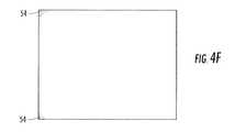
- FIGS. 4A-4Fillustrate a plurality of patterns of actinic radiation projected from the imager in order to selectively cure the entire area of the image plane with a substantially equivalent (or otherwise controlled) amount of actinic radiation per unit of surface area, wherein the patterns substantially correlate to the intensity profile of FIG. 3 to provide for a longer cumulative curing duration in the areas with relatively low intensity as compared to the areas with relatively high intensity;
- FIGS. 5A-5Cis a perspective view similar to FIG. 2 but illustrating the imager projecting a plurality of patterns that substantially correlate to a determined intensity profile to provide a substantially equivalent (or otherwise controlled) amount of actinic radiation per unit of surface area of the star-shaped pattern of the part being produced by the three-dimensional modeler;
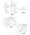
- FIGS. 6A-6Fillustrate the components and method of determining the intensity profile with a manually-operated sensor assembly, wherein the sensor assembly comprises a radiometer ( FIG. 6A ) with a probe and filter device ( FIG. 6B ) that is moved ( FIGS. 6C and 6D ) along a grid ( FIG. 6E ) positioned proximate the image plane to determine the actinic radiation intensity data ( FIG. 6F ) for each section of the grid to determine the intensity profile of the actinic radiation projected from the imager;
- the sensor assemblycomprises a radiometer ( FIG. 6A ) with a probe and filter device ( FIG. 6B ) that is moved ( FIGS. 6C and 6D ) along a grid ( FIG. 6E ) positioned proximate the image plane to determine the actinic radiation intensity data ( FIG. 6F ) for each section of the grid to determine the intensity profile of the actinic radiation projected from the imager;
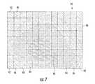
- FIG. 7illustrates an alternative technique to determine the intensity profile of the actinic radiation projected from the imager, wherein a sheet (comprising grid lines) of radiation-sensitive material is positioned proximate the image plane (not shown) and exposed to a full exposure of actinic radiation (the entire sheet is exposed for the same amount of time) to represent the actinic radiation intensity across the entire image plane, such that the exposed sheet can be scanned by a scanner to determine the intensity profile of the actinic radiation projected from the imager;
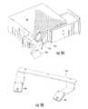
- FIG. 8illustrates yet another alternative technique to determine the intensity profile of the actinic radiation projected from the imager, wherein a scanner is positioned proximate the image plane of the three-dimensional modeler (for example, the prior art modeler of FIG. 1 ) such that the scanner is exposed to a full exposure of actinic radiation (the entire image plane is exposed for the same amount of time) to determine the intensity profile of the actinic radiation projected from the imager;
- a scanneris positioned proximate the image plane of the three-dimensional modeler (for example, the prior art modeler of FIG. 1 ) such that the scanner is exposed to a full exposure of actinic radiation (the entire image plane is exposed for the same amount of time) to determine the intensity profile of the actinic radiation projected from the imager;
- FIGS. 9A-9Care perspective views of a diffuser and intensity profiler in accordance with yet another embodiment of the present invention, wherein the diffuser of FIG. 9A is selectively moveable proximate the imager to diffuse the actinic radiation of the imager, the intensity profiler of FIG. 9B comprises two actinic radiation sensors to measure the amount of diffused actinic radiation, and a portion of the three-dimensional modeler of FIG.
- FIGCillustrating the respective locations of the diffuser and intensity profiler, wherein the diffuser and intensity profiler are adapted to automatically determine the intensity profile of the actinic radiation projected from the imager (by the imager projecting individual sections of a grid and the intensity profiler measuring the diffused actinic radiation) and/or to automatically detect changes over time in the overall intensity and/or changes in the intensity profiler by periodically determining the intensity profile; and
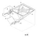
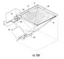
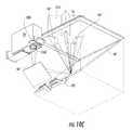
- FIGS. 10A-10Care perspective views of the operation of the methods and apparatus of one embodiment of the present invention, wherein the determined intensity profile of the actinic radiation projected from the imager is illustrated in FIG. 10A , a portion of the intensity profile defining the highest intensity of the actinic radiation is determined and a center of the part (the star-shaped part) is positioned proximate the portion of the intensity profile defining the highest intensity of the actinic radiation (as opposed to positioning the part in the center of the image plane as is typically done in prior art three-dimensional models), as illustrated in FIG. 10B , and a plurality of patterns ( FIGS.
- FIGS. 10B and 10Cillustrate the three-dimensional part comprising multiple layers of selectively cured solidifiable liquid material extending opposite the direction from which the actinic radiation is projected onto the image plane from the imager (via the two mirrors).
- Imagers of three-dimensional modelerstypically have a non-uniform intensity of actinic radiation that is projected along the x- and y-axes of the two-dimensional image plane.
- FIG. 3illustrates an intensity profile of the actinic radiation projected from an imager in accordance with one embodiment of the invention.
- the hatched regionsdefine areas of different intensity of actinic radiation, wherein the highest intensity corresponds to the denser hatch and vice versa.
- “intensity”primarily refers to the energy density of the actinic radiation. The energy density is important because the amount of curing of the solidifiable liquid material is directly related to the amount of energy projected onto the solidifiable liquid material.
- a portion of a part being produced from the solidifiable liquid materialmay grow an undesirable amount if exposed to too much energy, thus making the part oversized and/or disproportionate.
- a portion of a part being produced from the solidifiable liquid materialmay not grow enough if exposed to too little energy, thus making the part undersized and/or having inadequate part strength.
- the solidifiable liquid material used with the present inventionis any radiation curable composition that is converted from a generally liquid or thixotropic state to a generally solid state when exposed to a certain amount of actinic radiation.
- a solidifiable liquid material adapted for use with certain embodiments of the present inventionare disclosed in U.S. Pat. No. 7,358,283 and U.S. patent application Ser. No. 12/203,177 filed on Sep. 3, 2008, both of which are assigned to the present assignee, and the disclosures of which are incorporated by reference in their entireties.
- Further embodiments of the present inventioninclude any generally liquid material that may be solidified by exposure to actinic radiation.
- a “single layer” of solidifiable liquid materialcan be any amount of material applied in any fashion that is exposed to actinic radiation to selectively cure a portion of the solidifiable liquid material prior to the addition of any new material (the next layer) proximate the image plane. Therefore, a single layer may be defined by multiple individual layers of material if all those layers are exposed to the actinic radiation together. Typically, a single layer of material is provided proximate the image plane, the material is selectively cured and the cured material is removed relative to the image plane while becoming a layer of the part being produced and the uncured material is replaced or supplemented with uncured material to define the next single layer of material.
- the intensity of some imagersmay be only 25% in the corners of the image plane when compared to the intensity at the center or the middle area of the image plane.
- the solidifiable liquid material proximate the middle of the image planewill be over-exposed in order for the corner areas to be adequately cured or the solidifiable liquid material proximate the corners will be under-exposed in order for the middle area to properly cured.
- the present inventionmeasures such differences in the intensity of actinic radiation and compensates for such differences to provide a substantially equivalent amount of actinic radiation per unit of surface area.
- Certain other embodiments of the present inventionprovide substantially controlled amounts of actinic radiation (that are not necessarily equivalent) that enable the layers of the part to be cured in a controlled fashion to produce the part as desired.
- the intensity profile 30illustrates the different intensities of actinic radiation using hatched regions 32 - 42 (the right side of FIG. 3 provides a scale of the respective hatch densities).
- the region with the highest intensity, region 32is illustrated with the densest hatch, whereas the region with the lowest intensity, region 42 , is illustrated with the least dense hatch.
- the x-axis of the image planeis illustrated from 0 to 1000, and the y-axis of the image plane is illustrated from 0 to 700; however, image planes of further embodiments of the present invention may comprise axes with any numbering, may comprise any overall size, and/or may comprise any shape.
- the regions 32 - 42are illustrated as having lines between the regions, similar to topography lines on a map; however, it should be appreciated that the regions do not necessarily define a consistent intensity but merely represent a range of intensities such that there is a generally linear relationship in average intensity from the highest intensity in region 32 to the lowest intensity in region 42 without any substantial changes at the lines between regions.
- the region of highest intensity, region 32is generally centered along the x-axis and slightly below center along the y-axis; however, the intensity profiles of other three-dimensional modelers in accordance with the present invention may define any relative orientations, sizes, distribution, etc. of the regions of intensity.
- FIGS. 4A-4Fillustrate how the determined intensity profile of FIG. 3 may be used to improve the production of the part using the three-dimensional modeler.
- the methods and apparatus of the present inventionproject a plurality of patterns onto the layer of solidifiable liquid material to selectively cure the material in the shape of the two-dimensional pattern.
- the two-dimensional pattern being selectively curedis the entire surface area of the image plane, for illustrative purposes, but a more practical use of the plurality of patterns is also illustrated in FIGS. 5A-5C discussed below.
- the intensity profile 30 illustrated in FIG. 3must be determined (as discussed below). Once the intensity profile 30 is determined, the control system of the three-dimensional modeler controls the imager to project a plurality of patterns that are substantially correlated to the intensity profile of the actinic radiation.
- “correlate”means that the shapes of the individual patterns of the plurality of patterns depend in part upon the determined intensity profile. Correlation does not necessarily mean that the patterns of the actinic radiation correspond exactly to the regions of the intensity profile, as shown in FIGS.
- correlationsimply means that the intensity profile is taken into consideration when shapes of the individual patterns of the plurality of patterns are selected (preferably automatically, but also possibly manually) for the layers of the part to be produced with the three-dimensional modeler.
- the plurality of patterns of FIG. 4A-4Fare projected onto the layer of solidifiable liquid material proximate the image plane to expose the material to a substantially equivalent (or otherwise controlled) amount of actinic radiation per unit of surface area of the solidifiable liquid material.
- the pattern 44 of actinic radiation of FIG. 4Ais substantially the entire two-dimensional area of the image plane, as the cross-sectional area of the part (or at least the single layer of the part) being produced in FIGS. 4A-4F is the entire two-dimensional area of the image plane.
- the pattern 44is projected onto the image plane a sufficient amount of time, for example between three and ten seconds, to adequately cure (to generally cure the area the predetermined amount in order to produce the desired part) the material corresponding to region 32 (see FIG. 3 ) of the intensity profile 30 .
- pattern 46 of FIG. 4BThe next pattern in the plurality of patterns of actinic radiation projected onto the solidifiable liquid material proximate the image plane is pattern 46 of FIG. 4B (the actinic radiation is represented by the hatched area and a lack of actinic radiation is represented by a lack of hatch). Pattern 46 is projected a sufficient amount of time, for example less than one second, to adequately cure the material corresponding to region 34 (see FIG. 3 ) of the intensity profile 30 . Because region 34 is exposed to actinic radiation during pattern 44 , the amount of time that pattern 46 is projected onto the material is based upon the amount of additional actinic radiation region 34 needs so that region 34 is exposed to a substantially equivalent amount of actinic radiation per unit of surface area as region 32 . In other words, the amount of time pattern 46 is projected corresponds to the difference in intensities of regions 32 and 34 of the intensity profile of FIG. 3 .
- the intensities of regions such as regions 32 and 34are average intensities for the respective region, it should be appreciated that not every point in regions 32 and 34 are exposed to the exact same amount of actinic radiation.
- various embodiments of the present inventionbase the number of patterns in the plurality of patterns, the projection time of the patterns of the plurality of patterns, and other parameters in an attempt to project substantially equivalent amounts of actinic radiation per unit of surface area. Accordingly, it should be appreciated that a general relationship between the number of patterns in the plurality of patterns (for a given layer of the part) and the equivalence in actinic radiation exists such that providing a greater number of patterns provides improved equivalence in actinic radiation exposure and vice versa. Still further relationships between the various parameters would be appreciated by those skilled in the art and are included within the scope of the present invention.
- pattern 48 of FIG. 4Cis the next pattern (following pattern 46 of FIG. 4B ) in the plurality of patterns of actinic radiation projected onto the solidifiable liquid material proximate the image plane. Pattern 48 is projected a sufficient amount of time to adequately cure the material corresponding to region 36 (see FIG. 3 ) of the intensity profile 30 in a similar fashion as discussed above with respect to pattern 46 .
- pattern 50 of FIG. 4Dis the next pattern to adequately cure region 38 ;
- pattern 52 of FIG. 4Eis the next pattern to adequately cure region 40 ;
- pattern 54 of FIG. 4Fis the next pattern to adequately cure region 42 .
- the entire layer of solidifiable materialis cured with a substantially equivalent amount of actinic radiation per unit of surface area with an imager that projects the intensity profile of FIG. 3 that does not define a substantially equivalent amount of actinic radiation (intensity) per unit of surface area.
- FIGS. 5A-5Ca method of producing a star-shaped cross-sectional area of a part is illustrated.
- the control system of the three-dimensional modelerdetermines that a certain number patterns should be projected to adequately cure the star-shaped area out of the solidifiable liquid material 12 provided opposite the image plane 16 from the mirrors 60 and imager 20 .
- three patternsdefine the plurality of patterns to be projected for the single layer of solidifiable liquid material.
- FIGS. 5A-5Cillustrate the projecting of actinic radiation in a plurality of patterns to selectively cure a single layer of solidifiable liquid material.
- the phrase “projecting the actinic radiation in a plurality of patterns to selectively cure the single layer of the solidifiable liquid material”is defined as chronologically projecting two or more different patterns of actinic radiation on a single layer of solidifiable liquid material, similar to the chronology of patterns illustrated in FIGS. 4A-4F , in FIGS. 5A-5C , and in FIGS. 10B-10C . Still further embodiments of the present invention use the methods and apparatus of this invention to produce parts having a variety of shapes and/or using alternative numbers of different patterns to define the plurality of patterns for a single layer of material.
- FIGS. 6A-10Care provided to illustrate methods and apparatus for determining the intensity profile. Further embodiments of the present invention include additional methods and apparatus for determining the intensity profile.
- FIGS. 6A-6Fillustrate a first apparatus and associated method for determining the intensity profile of the actinic radiation with a manually-operated sensor assembly 62 .
- the sensor assembly 62 of FIG. 6Acomprises a radiometer having a probe 64 and a filter device 66 , wherein the probe comprises any type of actinic radiation sensor.
- the sensor assemblyalso comprises a display unit 68 used in conjunction with the probe to display the values of actinic radiation to the operator for the operator to manually record the values.
- FIG. 6Billustrates the probe 64 inserted into the filter device 66 , such that the filter device filters the actinic radiation measured by the probe.
- FIG. 6C and 6Dillustrate an operator moving the probe 64 (along with filter device 66 ) along a grid 70 that defines a plurality of grid sections 72 .
- FIG. 6Eillustrates the grid that is placed proximate the image plane 16 of the three-dimensional modeler 10 , wherein the grid of FIG. 6E defines 9 ⁇ 12 (108 total) grid sections for the operator to measure.
- the operatormeasures each grid section twice, once with the probe oriented a first direction (for example, in FIG. 6C ) and a second time with the probe oriented a second direction (for example, in FIG. 6D in a position that is 180 opposite the position of FIG. 6C ).
- the operatorrecords all of the measured values of actinic radiation intensity data, such as on a chart as in FIG. 6F , that is averaged and entered into the control system for the three-dimensional modeler, such that the modeler, or other software used in conjunction with the three-dimensional modeler control system, is able to determine the intensity profile 30 .
- the two values for each grid sectionare preferably averaged to provide a more accurate representation of the intensity profile; however, further embodiments of the present invention may utilize each individual value and/or may provide more or less grid sections to provide more or less resolution to the determined intensity profile.
- FIG. 7illustrates a sheet 80 , comprising gridlines 82 of radiation-sensitive material, that has been exposed to the actinic radiation for a certain duration of time.
- the sheetis sensitive to light or other actinic radiation such that the sheet changes color or shade of color (for example, with grey-scaling) in response to being exposed to an amount of energy.
- the sheet 80is positioned proximate the image plane (such as the image plane 16 of FIG. 1 ) and exposed to a full exposure of actinic radiation, such that the entire sheet is exposed for the same amount of time.
- the sheet 80then changes color, shade, or the like to represent the actinic radiation intensity across the entire image plane, thus depicting the intensity profile.
- the intensity profile illustrated on the sheet 80 of FIG. 7depicts the intensity profile 30 of FIG. 3 , wherein regions 82 - 92 of FIG. 7 correspond to regions 32 - 42 , respectively (though it should be appreciated that the boundary lines between regions would likely not appear on the sheet 80 for the reasons described above with respect to FIG. 3 ).
- the exposed sheet 80may then be scanned using a conventional scanner and software capable of taking the scanned colors, shades, or the like and determining the intensity profile therefrom.
- One advantage of the apparatus and method of FIG. 7is that it would allow determination of the intensity profile after the end user has taken possession of the three-dimensional modeler and without the need for a field engineer to travel to the location of the three-dimensional modeler.
- the apparatus and method of FIGS. 6A-6Fare preferably used/performed prior to, during, or immediately after the assembly of the three-dimensional modeler or are used/performed by a trained field engineer servicing a used three-dimensional modeler
- the apparatus and method of FIG. 7may be performed in part by the end user.
- the end userwould receive (from the organization responsible for servicing the modeler) at least one sheet 80 of radiation-sensitive material with instructions to place the sheet on the image plane and have the imager project a full exposure of actinic radiation for a certain duration of time. Once the sheet 80 has been exposed a sufficient amount, the end user could simply mail the sheet to the organization responsible for servicing the modeler, and the organization would scan the sheet to determine the intensity profile and then remotely communicate (via the internet, wireless device, or other communication device) the intensity profile to the three-dimensional modeler to effectively calibrate and/or re-calibrate the modeler with the intensity profile data. Still further advantages are achieved by the various apparatus and methods of the present invention.
- FIG. 8Yet another apparatus and method for determining the intensity profile of the actinic radiation projected from the imager is illustrated in FIG. 8 .
- a scanner device 96can be placed directly on the image plane, with the radiation-sensitive portion (not shown) facing the direction of the actinic radiation. Accordingly, the embodiment of FIG. 8 effectively eliminates the intermediate sheet of FIG. 7 , such that the scanner device 96 directly measures the projected actinic radiation to determine the intensity profile.
- the determined intensity profilemay subsequently be communicated (either directly or indirectly) to the three-dimensional modeler to effectively calibrate and/or re-calibrate the modeler with the intensity profile data.
- the scannercan measure the projected actinic radiation directly (such as described above) or indirectly (such as by using a diffuser in a manner similar to the method described below with respect to FIGS. 9A-9C or by using other radiation redirecting or filtering devices).
- a diffuser 100 and intensity profiler 102are provided to allow automatic determinations of the intensity profile of actinic radiation projected by the imager 20 .
- the diffuser 100 of FIG. 9Ais rotatably attached proximate the imager 20 , such that the diffuser is selectively moveable to be positioned in front of the lens 104 of the imager.
- the diffuser 100diffuses the actinic radiation of the imager 20 , such that the actinic radiation is generally scattered relative to its undiffused trajectory.
- FIG. 9Bcomprises two actinic radiation sensors 106 (further embodiments comprise at least one actinic radiation sensor) that measure the actinic radiation, in particular the diffused actinic radiation.
- FIG. 9Cshows the relative positioning of the diffuser and intensity profiler relative to the other components of the three-dimensional modeler.
- the diffuser and intensity profiler of this exemplary embodimentare adapted to be permanently attached to the three-dimensional modeler, unlike the previously discussed embodiments. Accordingly, it is desirable, though not necessary, that the diffuser and/or intensity profiler not be positioned in a way that would adversely affect the projection of actinic radiation during the normal operation of the three-dimensional modeler.
- the diffuseris rotatably attached proximate the imager 20 , and the intensity profiler 102 is mounted generally between the two mirrors 60 , but in such a way that the intensity profiler does not interfere with the normal projection of actinic radiation from the imager to the image plane.
- the diffuser 100is selectively positioned over the lens 104 of the imager 20 to diffuse the projected actinic radiation so that a portion of the actinic radiation is directed to one or both of the actinic radiation sensors 106 of the intensity profiler 102 .
- Further embodimentsinclude alternative methods and/or intensity profilers for sensing the actinic radiation to determine the intensity profile.
- the diffuser 100is positioned in front of lens 104 of imager 20 (as shown in phantom in FIG. 9A ).
- the imager 20projects small regions of actinic radiation, such as square or rectangular grid sections comparable to the grid sections of FIGS. 6E and 7 , sequentially in such a way that the intensity profiler 102 is able to measure the amount of diffused radiation corresponding to each projected grid section of actinic radiation and transfer such measurements to the control system of the three-dimensional modeler.
- the measurements from the intensity profiler 102 of FIG. 9Cmay be used (in an automated manner comparable to the use of the chart of FIG.
- this methodcan provide periodic determinations of the intensity profile to continuously recalibrate the modeler by updating the plurality of patterns per layer as the intensity profile changes over time and/or as the overall intensity diminishes over time.
- Still further embodiments of the present inventioninclude additional and/or alternative method and apparatus for determining the intensity profile of the actinic radiation projected from the imager.
- FIGS. 10A-10Cadditional methods and apparatus of the present invention are disclosed, wherein the part is positioned to be proximate the portion of the intensity profile defining the highest intensity of actinic radiation.
- FIG. 10Arepresents a three-dimensional modeler in which the intensity profile 30 ′ defines a region 32 ′ of highest intensity (comparable to the region 32 of FIG. 3 ) that is offset in both the x-axis and the y-axis.
- the control system of the three-dimensional modelerpositions a center of the part to be produced proximate a portion (region 32 ′) of the intensity profile defining the highest intensity of the actinic radiation.
- FIG. 10Billustrates the center of the part 110 as being positioned proximate the region 32 ′ rather than in the center or in a corner or side, which are often the default positions for parts. If multiple individual parts are being produced simultaneously, the parts may be oriented in such a way that the center of the collective parts (also call the part herein) is positioned proximate a portion (region 32 ′) of the intensity profile defining the highest intensity of the actinic radiation. It should also be appreciated that the center of the part is generally determined based upon all of the layers of the part, as parts may have many different layers that define different centers, so the average center is preferably used for such parts.
- FIG. 10Billustrates the projections of a first pattern 44 ′′ of the plurality of patterns
- FIG. 10Cillustrates a second pattern 46 ′′ of the plurality of patterns (additional patterns may also be projected depending upon the intensity profile). Because the cure time for each layer is generally governed by the lowest intensity of any area to be cured for that particular layer, the speed of production can be increased by positioning the part proximate the highest intensity.
- the present inventionprovides for the production of three-dimensional parts having superior part quality and/or with faster build times relative to parts produced by conventional methods and apparatus.
Landscapes
- Chemical & Material Sciences (AREA)
- Engineering & Computer Science (AREA)
- Materials Engineering (AREA)
- Manufacturing & Machinery (AREA)
- Physics & Mathematics (AREA)
- Mechanical Engineering (AREA)
- Optics & Photonics (AREA)
Abstract
Description
Claims (15)
Priority Applications (1)
| Application Number | Priority Date | Filing Date | Title |
|---|---|---|---|
| US13/238,166US8568646B2 (en) | 2008-10-20 | 2011-09-21 | Compensation of actinic radiation intensity profiles for three-dimensional modelers |
Applications Claiming Priority (2)
| Application Number | Priority Date | Filing Date | Title |
|---|---|---|---|
| US12/254,579US8048359B2 (en) | 2008-10-20 | 2008-10-20 | Compensation of actinic radiation intensity profiles for three-dimensional modelers |
| US13/238,166US8568646B2 (en) | 2008-10-20 | 2011-09-21 | Compensation of actinic radiation intensity profiles for three-dimensional modelers |
Related Parent Applications (1)
| Application Number | Title | Priority Date | Filing Date |
|---|---|---|---|
| US12/254,579DivisionUS8048359B2 (en) | 2008-10-20 | 2008-10-20 | Compensation of actinic radiation intensity profiles for three-dimensional modelers |
Publications (2)
| Publication Number | Publication Date |
|---|---|
| US20120007288A1 US20120007288A1 (en) | 2012-01-12 |
| US8568646B2true US8568646B2 (en) | 2013-10-29 |
Family
ID=42045268
Family Applications (2)
| Application Number | Title | Priority Date | Filing Date |
|---|---|---|---|
| US12/254,579Active2029-03-07US8048359B2 (en) | 2008-10-20 | 2008-10-20 | Compensation of actinic radiation intensity profiles for three-dimensional modelers |
| US13/238,166ActiveUS8568646B2 (en) | 2008-10-20 | 2011-09-21 | Compensation of actinic radiation intensity profiles for three-dimensional modelers |
Family Applications Before (1)
| Application Number | Title | Priority Date | Filing Date |
|---|---|---|---|
| US12/254,579Active2029-03-07US8048359B2 (en) | 2008-10-20 | 2008-10-20 | Compensation of actinic radiation intensity profiles for three-dimensional modelers |
Country Status (6)
| Country | Link |
|---|---|
| US (2) | US8048359B2 (en) |
| EP (2) | EP2684679B1 (en) |
| JP (1) | JP5379236B2 (en) |
| CN (1) | CN102186653B (en) |
| TW (1) | TW201036804A (en) |
| WO (1) | WO2010048082A2 (en) |
Cited By (25)
| Publication number | Priority date | Publication date | Assignee | Title |
|---|---|---|---|---|
| US9633470B2 (en) | 2014-11-11 | 2017-04-25 | Roland Dg Corporation | Generating slice data representing a cross section cut from a three-dimensional modeled object |
| EP3453521A1 (en)* | 2017-09-06 | 2019-03-13 | Ackuretta Technologies Pvt. Ltd. | Digital light processing in three-dimensional printing system and method for improving the production rate of 3d printing |
| US10843265B2 (en) | 2015-10-30 | 2020-11-24 | Seurat Technologies, Inc. | Enclosed additive manufacturing system |
| US11014302B2 (en) | 2017-05-11 | 2021-05-25 | Seurat Technologies, Inc. | Switchyard beam routing of patterned light for additive manufacturing |
| US11148319B2 (en) | 2016-01-29 | 2021-10-19 | Seurat Technologies, Inc. | Additive manufacturing, bond modifying system and method |
| US11179891B2 (en) | 2019-03-15 | 2021-11-23 | General Electric Company | Method and apparatus for additive manufacturing with shared components |
| US11433617B2 (en) | 2019-01-29 | 2022-09-06 | General Electric Company | Method and apparatus for process monitoring in additive manufacturing utilizing an image of a negative structure |
| US11498283B2 (en) | 2019-02-20 | 2022-11-15 | General Electric Company | Method and apparatus for build thickness control in additive manufacturing |
| US11541481B2 (en) | 2018-12-19 | 2023-01-03 | Seurat Technologies, Inc. | Additive manufacturing system using a pulse modulated laser for two-dimensional printing |
| US11701819B2 (en) | 2016-01-28 | 2023-07-18 | Seurat Technologies, Inc. | Additive manufacturing, spatial heat treating system and method |
| US11731367B2 (en) | 2021-06-23 | 2023-08-22 | General Electric Company | Drive system for additive manufacturing |
| US11794412B2 (en) | 2019-02-20 | 2023-10-24 | General Electric Company | Method and apparatus for layer thickness control in additive manufacturing |
| US11813799B2 (en) | 2021-09-01 | 2023-11-14 | General Electric Company | Control systems and methods for additive manufacturing |
| US11826950B2 (en) | 2021-07-09 | 2023-11-28 | General Electric Company | Resin management system for additive manufacturing |
| US11951679B2 (en) | 2021-06-16 | 2024-04-09 | General Electric Company | Additive manufacturing system |
| US11958249B2 (en) | 2021-06-24 | 2024-04-16 | General Electric Company | Reclamation system for additive manufacturing |
| US11958250B2 (en) | 2021-06-24 | 2024-04-16 | General Electric Company | Reclamation system for additive manufacturing |
| US12011873B2 (en) | 2018-12-14 | 2024-06-18 | Seurat Technologies, Inc. | Additive manufacturing system for object creation from powder using a high flux laser for two-dimensional printing |
| US12162074B2 (en) | 2020-11-25 | 2024-12-10 | Lawrence Livermore National Security, Llc | System and method for large-area pulsed laser melting of metallic powder in a laser powder bed fusion application |
| US12285908B2 (en) | 2020-11-20 | 2025-04-29 | General Electric Company | Foil interaction device for additive manufacturing |
| US12296535B2 (en) | 2021-08-24 | 2025-05-13 | General Electric Company | Attachment structure for additive manufacturing |
| US12370741B2 (en) | 2021-08-13 | 2025-07-29 | General Electric Company | Material deposition assembly for additive manufacturing |
| US12403654B2 (en) | 2022-09-30 | 2025-09-02 | General Electric Company | Systems and methods for additive manufacturing |
| US12409604B2 (en) | 2022-03-23 | 2025-09-09 | General Electric Company | Systems and methods for additive manufacturing |
| US12434436B2 (en) | 2021-02-26 | 2025-10-07 | General Electric Company | Accumalator assembly for additive manufacturing |
Families Citing this family (45)
| Publication number | Priority date | Publication date | Assignee | Title |
|---|---|---|---|---|
| WO2013048997A2 (en) | 2011-09-26 | 2013-04-04 | 3D Systems, Inc. | Solid imaging systems, components thereof, and methods of solid imaging |
| US9751262B2 (en) | 2013-06-28 | 2017-09-05 | General Electric Company | Systems and methods for creating compensated digital representations for use in additive manufacturing processes |
| KR101872628B1 (en) | 2014-01-16 | 2018-06-28 | 휴렛-팩커드 디벨롭먼트 컴퍼니, 엘.피. | Generating a three-dimensional object |
| US10252474B2 (en) | 2014-01-16 | 2019-04-09 | Hewlett-Packard Development Company, L.P. | Temperature determination based on emissivity |
| US10220564B2 (en) | 2014-01-16 | 2019-03-05 | Hewlett-Packard Development Company, L.P. | Generating three-dimensional objects |
| US10889059B2 (en) | 2014-01-16 | 2021-01-12 | Hewlett-Packard Development Company, L.P. | Generating three-dimensional objects |
| US9486878B2 (en) | 2014-06-20 | 2016-11-08 | Velo3D, Inc. | Apparatuses, systems and methods for three-dimensional printing |
| KR101914886B1 (en)* | 2014-07-30 | 2018-11-02 | 디더블유에스 에스.알.엘. | Improved method for controlling the activity of at least two light radiation sources belonging to a stereolithography machine |
| DE102015017470B4 (en) | 2014-08-22 | 2025-07-17 | Divergent Technologies, Inc. | FAILURE DETECTION FOR ADDITIVE MANUFACTURING SYSTEMS |
| TWI568601B (en)* | 2014-10-02 | 2017-02-01 | 三緯國際立體列印科技股份有限公司 | Three dimensional printing apparatus and prining method thereof |
| KR102549649B1 (en)* | 2014-11-14 | 2023-06-29 | 가부시키가이샤 니콘 | Shaping device and a shaping method |
| US10786948B2 (en) | 2014-11-18 | 2020-09-29 | Sigma Labs, Inc. | Multi-sensor quality inference and control for additive manufacturing processes |
| CN107428081B (en) | 2015-01-13 | 2020-07-07 | 西格马实验室公司 | Materials identification system and method |
| DE102015103389A1 (en) | 2015-03-09 | 2016-09-15 | Schultheiss Gmbh | Method and device for correcting an inhomogeneous intensity distribution of a radiation field generated by a radiation source |
| NL2014678B1 (en)* | 2015-04-20 | 2017-01-20 | Bond High Performance 3D Tech B V | Fused deposition modeling. |
| CN106273444B (en)* | 2015-06-02 | 2018-07-20 | 北京大业三维科技有限公司 | A kind of demoulding control method and device of 3D printing system |
| CN106273445B (en)* | 2015-06-02 | 2018-05-04 | 北京大业三维科技有限公司 | The characteristic test method and device of a kind of 3D printer |
| CA3031329A1 (en)* | 2015-07-18 | 2017-01-26 | Vulcanforms Inc. | Additive manufacturing by spatially controlled material fusion |
| EP3135459A1 (en)* | 2015-08-31 | 2017-03-01 | Nederlandse Organisatie voor toegepast- natuurwetenschappelijk onderzoek TNO | Method and apparatus for layerwise production of a tangible object |
| US10207489B2 (en)* | 2015-09-30 | 2019-02-19 | Sigma Labs, Inc. | Systems and methods for additive manufacturing operations |
| US10065270B2 (en) | 2015-11-06 | 2018-09-04 | Velo3D, Inc. | Three-dimensional printing in real time |
| US10286603B2 (en) | 2015-12-10 | 2019-05-14 | Velo3D, Inc. | Skillful three-dimensional printing |
| US20170239719A1 (en) | 2016-02-18 | 2017-08-24 | Velo3D, Inc. | Accurate three-dimensional printing |
| US9835568B2 (en) | 2016-04-12 | 2017-12-05 | General Electric Company | Defect correction using tomographic scanner for additive manufacturing |
| CN108883577B (en)* | 2016-05-12 | 2021-01-01 | 惠普发展公司,有限责任合伙企业 | Three-dimensional (3D) printing |
| EP3492244A1 (en) | 2016-06-29 | 2019-06-05 | VELO3D, Inc. | Three-dimensional printing system and method for three-dimensional printing |
| US11691343B2 (en) | 2016-06-29 | 2023-07-04 | Velo3D, Inc. | Three-dimensional printing and three-dimensional printers |
| EP3436240B1 (en) | 2016-07-29 | 2022-08-31 | Hewlett-Packard Development Company, L.P. | Build material layer quality level determination |
| CN106166841B (en)* | 2016-08-02 | 2018-07-31 | 苏州秉创科技有限公司 | A kind of 3D printing equipment reversely printed |
| CN106273487B (en)* | 2016-08-17 | 2018-06-12 | 苏州秉创科技有限公司 | A kind of DLP printing devices projecting apparatus light intensity autoalign unit and calibration method |
| CN106113507B (en)* | 2016-08-17 | 2019-10-01 | 苏州秉创科技有限公司 | A kind of 3D printing equipment projector light intensity autoalign unit |
| US20180093418A1 (en) | 2016-09-30 | 2018-04-05 | Velo3D, Inc. | Three-dimensional objects and their formation |
| US20180126460A1 (en) | 2016-11-07 | 2018-05-10 | Velo3D, Inc. | Gas flow in three-dimensional printing |
| US20180186082A1 (en) | 2017-01-05 | 2018-07-05 | Velo3D, Inc. | Optics in three-dimensional printing |
| US10315252B2 (en) | 2017-03-02 | 2019-06-11 | Velo3D, Inc. | Three-dimensional printing of three-dimensional objects |
| US10449696B2 (en) | 2017-03-28 | 2019-10-22 | Velo3D, Inc. | Material manipulation in three-dimensional printing |
| DE102017110241A1 (en)* | 2017-05-11 | 2018-11-15 | Nanoscribe Gmbh | Method for generating a 3D structure by means of laser lithography and computer program product |
| TWI825023B (en)* | 2017-08-24 | 2023-12-11 | 日商索尼股份有限公司 | Light modeling device, lighting control method and lighting control program |
| US10272525B1 (en) | 2017-12-27 | 2019-04-30 | Velo3D, Inc. | Three-dimensional printing systems and methods of their use |
| US10144176B1 (en) | 2018-01-15 | 2018-12-04 | Velo3D, Inc. | Three-dimensional printing systems and methods of their use |
| US10875094B2 (en) | 2018-03-29 | 2020-12-29 | Vulcanforms Inc. | Additive manufacturing systems and methods |
| CN110394980A (en)* | 2018-04-24 | 2019-11-01 | 三纬国际立体列印科技股份有限公司 | 3D printing system |
| US12121964B2 (en) | 2018-11-07 | 2024-10-22 | James J. Myrick | Processes, compositions and systems for 2D and 3D printing |
| CA3148849A1 (en) | 2019-07-26 | 2021-02-04 | Velo3D, Inc. | Quality assurance in formation of three-dimensional objects |
| PL437982A1 (en)* | 2021-05-27 | 2022-11-28 | Skriware Spółka Z Ograniczoną Odpowiedzialnością | System for automatic detecting 3D printing errors |
Citations (66)
| Publication number | Priority date | Publication date | Assignee | Title |
|---|---|---|---|---|
| US796159A (en) | 1905-01-07 | 1905-08-01 | Rosa B Smolik | Apparatus for physical exercise. |
| CN1053843A (en) | 1989-12-22 | 1991-08-14 | 纳幕尔杜邦公司 | Solid imaging system |
| US5049901A (en) | 1990-07-02 | 1991-09-17 | Creo Products Inc. | Light modulator using large area light sources |
| US5182056A (en) | 1988-04-18 | 1993-01-26 | 3D Systems, Inc. | Stereolithography method and apparatus employing various penetration depths |
| US5184307A (en) | 1988-04-18 | 1993-02-02 | 3D Systems, Inc. | Method and apparatus for production of high resolution three-dimensional objects by stereolithography |
| US5247180A (en) | 1991-12-30 | 1993-09-21 | Texas Instruments Incorporated | Stereolithographic apparatus and method of use |
| FR2692053A1 (en) | 1992-06-05 | 1993-12-10 | Goreta Lucas | Model prodn. by selective photopolymerisation of liq. or powder - using active liq. crystal mask or active light source controlled by computer instead of controlled movement focused laser |
| DE9319405U1 (en) | 1993-12-17 | 1994-03-31 | Forschungszentrum Informatik an der Universität Karlsruhe, 76131 Karlsruhe | Device for producing a three-dimensional object (model) according to the principle of photofixing |
| WO1995015841A1 (en) | 1992-06-05 | 1995-06-15 | Finab Limited | Machine for making objects by selectively photopolymerising layered liquids or powders |
| WO1996000422A1 (en) | 1994-06-27 | 1996-01-04 | Hercules Incorporated | Programmable mask for producing three-dimensional objects |
| US5650260A (en) | 1993-10-14 | 1997-07-22 | Teijin Seiki Co., Ltd. | Method and apparatus for fabricating three-dimensional object |
| WO1998041944A1 (en) | 1997-03-19 | 1998-09-24 | Replicator Systems, Inc. | Apparatus and method for production of three-dimensional models by spatial light modulator |
| DE29911122U1 (en) | 1999-06-25 | 1999-09-30 | DeltaMed Medizinprodukte GmbH, 64546 Mörfelden-Walldorf | Device for producing a three-dimensional object |
| US5980913A (en) | 1994-12-19 | 1999-11-09 | Biochem Pharma, Inc. | Peptides having immunomodulatory activity |
| US6048487A (en) | 1988-09-26 | 2000-04-11 | 3D Systems, Inc. | Recoating stereolithographic layers |
| DE19929199A1 (en) | 1999-06-25 | 2001-01-18 | Hap Handhabungs Automatisierun | Method and device for producing a three-dimensional object |
| WO2001033511A2 (en) | 1999-11-03 | 2001-05-10 | Case Western Reserve University | System and method for producing a three-dimensional model |
| WO2001040866A2 (en) | 1999-11-29 | 2001-06-07 | Carl Johannes Fruth | Method and device for coating a substrate |
| EP1156922A1 (en) | 1998-10-12 | 2001-11-28 | Dicon A/S | Rapid prototyping apparatus and method of rapid prototyping |
| US6369814B1 (en) | 1999-03-26 | 2002-04-09 | Microsoft Corporation | Transformation pipeline for computing distortion correction geometry for any design eye point, display surface geometry, and projector position |
| US6391245B1 (en) | 1999-04-13 | 2002-05-21 | Eom Technologies, L.L.C. | Method for creating three-dimensional objects by cross-sectional lithography |
| EP1250997A1 (en) | 2001-04-20 | 2002-10-23 | Envision Technologies GmbH | Manufacturing device for three-dimensional object |
| US6500378B1 (en) | 2000-07-13 | 2002-12-31 | Eom Technologies, L.L.C. | Method and apparatus for creating three-dimensional objects by cross-sectional lithography |
| EP1270185A1 (en) | 2001-06-22 | 2003-01-02 | 3D Systems, Inc. | Recoating system and method for solid freeform fabrication |
| US6544698B1 (en) | 2001-06-27 | 2003-04-08 | University Of South Florida | Maskless 2-D and 3-D pattern generation photolithography |
| US20030074096A1 (en) | 2001-10-15 | 2003-04-17 | Suman Das | Solid freeform fabrication of structurally engineered multifunctional devices |
| WO2003059184A2 (en) | 2001-12-21 | 2003-07-24 | Biomat Sciences, Inc. | Process of making dental restorations |
| US6665048B2 (en) | 2002-01-22 | 2003-12-16 | Creo Inc. | Method for imaging a continuously moving object |
| US20040075882A1 (en) | 2002-08-24 | 2004-04-22 | Meisburger William Daniel | Continuous direct-write optical lithography |
| US20050032710A1 (en) | 2003-05-16 | 2005-02-10 | Kao Corporation | Alternative agent with vitamin D-like activity and an improving agent for intestinal function |
| US6855482B2 (en) | 2002-04-09 | 2005-02-15 | Day International, Inc. | Liquid transfer articles and method for producing the same using digital imaging photopolymerization |
| US20050056791A1 (en) | 2002-08-01 | 2005-03-17 | Donaghue David M. | Radiation detection apparatus |
| US6942830B2 (en) | 2000-04-17 | 2005-09-13 | Envisiontec Gmbh | Device and method for the production of three-dimensional objects |
| US20050248062A1 (en) | 2004-05-10 | 2005-11-10 | Alexandr Shkolnik | Process for the production of a three-dimensional object with resolution improvement by "pixel-shift" |
| US20050259785A1 (en) | 2000-09-27 | 2005-11-24 | Xiang Zhang | Dynamic mask projection stereo micro lithography |
| WO2005110722A1 (en) | 2004-05-10 | 2005-11-24 | Envisiontec Gmbh | Method for producing a three-dimensional object with resolution enhancement by means of pixel shift |
| US20050288813A1 (en) | 2003-10-14 | 2005-12-29 | Laixia Yang | Direct write and freeform fabrication apparatus and method |
| US6995830B2 (en) | 2003-12-22 | 2006-02-07 | Asml Netherlands B.V. | Lithographic projection apparatus and device manufacturing method |
| US6998219B2 (en) | 2001-06-27 | 2006-02-14 | University Of South Florida | Maskless photolithography for etching and deposition |
| US20060239588A1 (en) | 2005-04-01 | 2006-10-26 | 3D Systems, Inc. | Edge smoothness with low resolution projected images for use in solid imaging |
| US20060249884A1 (en) | 2005-05-03 | 2006-11-09 | 3D Systems, Inc. | Bubble-free cross-sections for use in solid imaging |
| US7162323B2 (en) | 2004-04-05 | 2007-01-09 | Hearing Aid Express, Inc. | Decentralized method for manufacturing hearing aid devices |
| US7195472B2 (en) | 2001-04-23 | 2007-03-27 | Envisiontec Gmbh | Apparatus and method for the non-destructive separation of hardened material layers from a flat construction plane |
| US20070179656A1 (en)* | 2003-05-01 | 2007-08-02 | David Eshed | Rapid prototyping apparatus |
| EP1849587A1 (en) | 2006-04-28 | 2007-10-31 | Envisiontec GmbH | Device and method for creating a three dimensional object using mask illumination |
| US20070259066A1 (en) | 2006-05-03 | 2007-11-08 | 3D Systems, Inc. | Material delivery tension and tracking system for use in solid imaging |
| US20070260349A1 (en) | 2006-04-28 | 2007-11-08 | Envisiontec Gmbh | Device and method for producing a three-dimensional object by means of mask exposure |
| US20080021586A1 (en) | 2006-07-19 | 2008-01-24 | Volker Schillen | Method and device for producing a three-dimensional object, and computer and data carrier useful therefor |
| US20080054531A1 (en) | 2006-08-29 | 2008-03-06 | 3D Systems, Inc. | Wall Smoothness, Feature Accuracy and Resolution In Projected Images Via Exposure Levels In Solid Imaging |
| US7358283B2 (en) | 2005-04-01 | 2008-04-15 | 3D Systems, Inc. | Radiation curable compositions useful in image projection systems |
| US7362355B1 (en) | 2003-08-04 | 2008-04-22 | Pixim, Inc. | Digital CMOS image sensor incorporating a programmable multi-functional lookup table |
| US20080113293A1 (en) | 2006-11-15 | 2008-05-15 | Alexandr Shkolnik | Continuous generative process for producing a three-dimensional object |
| US20080170122A1 (en) | 2007-01-11 | 2008-07-17 | Sanyo Electric Co., Ltd. | Image processor, driving assistance system, and out-of-position detecting method |
| US20080169586A1 (en) | 2007-01-17 | 2008-07-17 | Hull Charles W | Imager Assembly and Method for Solid Imaging |
| US20080169589A1 (en) | 2007-01-17 | 2008-07-17 | Sperry Charles R | Solid imaging apparatus and method |
| EP1946908A2 (en) | 2007-01-17 | 2008-07-23 | 3D Systems, Inc. | Solid imaging system with removal of excess uncured build material |
| US20080179787A1 (en) | 2007-01-17 | 2008-07-31 | Sperry Charles R | Elevator and method for tilting solid image build platform for reducing air entrainment and for build release |
| US20080179785A1 (en) | 2000-08-25 | 2008-07-31 | Geoffrey Robert Hammond | Process and Mold for Thermoforming Containers |
| US20080181977A1 (en) | 2007-01-17 | 2008-07-31 | Sperry Charles R | Brush assembly for removal of excess uncured build material |
| US20080217818A1 (en) | 2004-10-08 | 2008-09-11 | Holmboe Scott B | Stereolithographic Apparatus |
| US20080226346A1 (en) | 2007-01-17 | 2008-09-18 | 3D Systems, Inc. | Inkjet Solid Imaging System and Method for Solid Imaging |
| US20090133800A1 (en) | 2005-03-30 | 2009-05-28 | Jsr Corporation | Stereolithography method |
| US20090146344A1 (en) | 2007-10-26 | 2009-06-11 | Envisiontec Gmbh | Process and freeform fabrication system for producing a three-dimensional object |
| US20090191489A1 (en) | 1998-03-02 | 2009-07-30 | Torbjorn Sandstrom | Pattern generator |
| US7573561B2 (en) | 2001-06-27 | 2009-08-11 | University Of South Florida | Method and apparatus for maskless photolithography |
| US20100125356A1 (en) | 2008-11-18 | 2010-05-20 | Global Filtration Systems | System and Method for Manufacturing |
Family Cites Families (3)
| Publication number | Priority date | Publication date | Assignee | Title |
|---|---|---|---|---|
| JP3343968B2 (en)* | 1992-12-14 | 2002-11-11 | ソニー株式会社 | Bipolar semiconductor device and method of manufacturing the same |
| JPH0834063A (en)* | 1994-07-25 | 1996-02-06 | Toshiba Corp | Stereolithography method, apparatus therefor, and resin molding |
| US20050023710A1 (en)* | 1998-07-10 | 2005-02-03 | Dmitri Brodkin | Solid free-form fabrication methods for the production of dental restorations |
- 2008
- 2008-10-20USUS12/254,579patent/US8048359B2/enactiveActive
- 2009
- 2009-10-19EPEP13186155.1Apatent/EP2684679B1/enactiveActive
- 2009-10-19WOPCT/US2009/061159patent/WO2010048082A2/enactiveApplication Filing
- 2009-10-19JPJP2011532311Apatent/JP5379236B2/enactiveActive
- 2009-10-19CNCN200980141293.2Apatent/CN102186653B/enactiveActive
- 2009-10-19TWTW098135297Apatent/TW201036804A/enunknown
- 2009-10-19EPEP09748583.3Apatent/EP2344323B1/enactiveActive
- 2011
- 2011-09-21USUS13/238,166patent/US8568646B2/enactiveActive
Patent Citations (79)
| Publication number | Priority date | Publication date | Assignee | Title |
|---|---|---|---|---|
| US796159A (en) | 1905-01-07 | 1905-08-01 | Rosa B Smolik | Apparatus for physical exercise. |
| US5182056A (en) | 1988-04-18 | 1993-01-26 | 3D Systems, Inc. | Stereolithography method and apparatus employing various penetration depths |
| US5184307A (en) | 1988-04-18 | 1993-02-02 | 3D Systems, Inc. | Method and apparatus for production of high resolution three-dimensional objects by stereolithography |
| US6048487A (en) | 1988-09-26 | 2000-04-11 | 3D Systems, Inc. | Recoating stereolithographic layers |
| CN1053843A (en) | 1989-12-22 | 1991-08-14 | 纳幕尔杜邦公司 | Solid imaging system |
| US5049901A (en) | 1990-07-02 | 1991-09-17 | Creo Products Inc. | Light modulator using large area light sources |
| US5247180A (en) | 1991-12-30 | 1993-09-21 | Texas Instruments Incorporated | Stereolithographic apparatus and method of use |
| EP0676275A1 (en) | 1991-12-30 | 1995-10-11 | Texas Instruments Incorporated | Stereolithographic exposure head |
| FR2692053A1 (en) | 1992-06-05 | 1993-12-10 | Goreta Lucas | Model prodn. by selective photopolymerisation of liq. or powder - using active liq. crystal mask or active light source controlled by computer instead of controlled movement focused laser |
| WO1995015841A1 (en) | 1992-06-05 | 1995-06-15 | Finab Limited | Machine for making objects by selectively photopolymerising layered liquids or powders |
| US5650260A (en) | 1993-10-14 | 1997-07-22 | Teijin Seiki Co., Ltd. | Method and apparatus for fabricating three-dimensional object |
| DE9319405U1 (en) | 1993-12-17 | 1994-03-31 | Forschungszentrum Informatik an der Universität Karlsruhe, 76131 Karlsruhe | Device for producing a three-dimensional object (model) according to the principle of photofixing |
| WO1996000422A1 (en) | 1994-06-27 | 1996-01-04 | Hercules Incorporated | Programmable mask for producing three-dimensional objects |
| US5980913A (en) | 1994-12-19 | 1999-11-09 | Biochem Pharma, Inc. | Peptides having immunomodulatory activity |
| WO1998041944A1 (en) | 1997-03-19 | 1998-09-24 | Replicator Systems, Inc. | Apparatus and method for production of three-dimensional models by spatial light modulator |
| US6051179A (en) | 1997-03-19 | 2000-04-18 | Replicator Systems, Inc. | Apparatus and method for production of three-dimensional models by spatial light modulator |
| US20090191489A1 (en) | 1998-03-02 | 2009-07-30 | Torbjorn Sandstrom | Pattern generator |
| EP1156922A1 (en) | 1998-10-12 | 2001-11-28 | Dicon A/S | Rapid prototyping apparatus and method of rapid prototyping |
| DE69909136T2 (en) | 1998-10-12 | 2004-05-06 | Dicon A/S | RAPID PROTOTYPING DEVICE AND RAPID PROTOTYPING METHOD |
| US6369814B1 (en) | 1999-03-26 | 2002-04-09 | Microsoft Corporation | Transformation pipeline for computing distortion correction geometry for any design eye point, display surface geometry, and projector position |
| US6391245B1 (en) | 1999-04-13 | 2002-05-21 | Eom Technologies, L.L.C. | Method for creating three-dimensional objects by cross-sectional lithography |
| EP1192041A1 (en) | 1999-06-25 | 2002-04-03 | Hap Handhabungs-, Automatisierungs- und Präzisionstechnik GmbH | Method and device for producing an object by means of stereolithography |
| DE29911122U1 (en) | 1999-06-25 | 1999-09-30 | DeltaMed Medizinprodukte GmbH, 64546 Mörfelden-Walldorf | Device for producing a three-dimensional object |
| DE19929199A1 (en) | 1999-06-25 | 2001-01-18 | Hap Handhabungs Automatisierun | Method and device for producing a three-dimensional object |
| WO2001033511A2 (en) | 1999-11-03 | 2001-05-10 | Case Western Reserve University | System and method for producing a three-dimensional model |
| DE19957370A1 (en) | 1999-11-29 | 2001-06-13 | Carl Johannes Fruth | Method and device for coating a substrate |
| WO2001040866A2 (en) | 1999-11-29 | 2001-06-07 | Carl Johannes Fruth | Method and device for coating a substrate |
| US6942830B2 (en) | 2000-04-17 | 2005-09-13 | Envisiontec Gmbh | Device and method for the production of three-dimensional objects |
| US6500378B1 (en) | 2000-07-13 | 2002-12-31 | Eom Technologies, L.L.C. | Method and apparatus for creating three-dimensional objects by cross-sectional lithography |
| US20080179785A1 (en) | 2000-08-25 | 2008-07-31 | Geoffrey Robert Hammond | Process and Mold for Thermoforming Containers |
| US7088432B2 (en) | 2000-09-27 | 2006-08-08 | The Regents Of The University Of California | Dynamic mask projection stereo micro lithography |
| US20050259785A1 (en) | 2000-09-27 | 2005-11-24 | Xiang Zhang | Dynamic mask projection stereo micro lithography |
| US20020155189A1 (en) | 2001-04-20 | 2002-10-24 | Envision Technologies Gmbh, | Apparatus for manufacturing a three-dimensional object |
| US7052263B2 (en) | 2001-04-20 | 2006-05-30 | Envisiontec Gmbh | Apparatus for manufacturing a three-dimensional object |
| EP1250997A1 (en) | 2001-04-20 | 2002-10-23 | Envision Technologies GmbH | Manufacturing device for three-dimensional object |
| US7195472B2 (en) | 2001-04-23 | 2007-03-27 | Envisiontec Gmbh | Apparatus and method for the non-destructive separation of hardened material layers from a flat construction plane |
| EP1270185A1 (en) | 2001-06-22 | 2003-01-02 | 3D Systems, Inc. | Recoating system and method for solid freeform fabrication |
| US6998219B2 (en) | 2001-06-27 | 2006-02-14 | University Of South Florida | Maskless photolithography for etching and deposition |
| US6544698B1 (en) | 2001-06-27 | 2003-04-08 | University Of South Florida | Maskless 2-D and 3-D pattern generation photolithography |
| US7573561B2 (en) | 2001-06-27 | 2009-08-11 | University Of South Florida | Method and apparatus for maskless photolithography |
| US20030074096A1 (en) | 2001-10-15 | 2003-04-17 | Suman Das | Solid freeform fabrication of structurally engineered multifunctional devices |
| WO2003059184A2 (en) | 2001-12-21 | 2003-07-24 | Biomat Sciences, Inc. | Process of making dental restorations |
| US6665048B2 (en) | 2002-01-22 | 2003-12-16 | Creo Inc. | Method for imaging a continuously moving object |
| US6855482B2 (en) | 2002-04-09 | 2005-02-15 | Day International, Inc. | Liquid transfer articles and method for producing the same using digital imaging photopolymerization |
| US20050056791A1 (en) | 2002-08-01 | 2005-03-17 | Donaghue David M. | Radiation detection apparatus |
| US20040075882A1 (en) | 2002-08-24 | 2004-04-22 | Meisburger William Daniel | Continuous direct-write optical lithography |
| US20070179656A1 (en)* | 2003-05-01 | 2007-08-02 | David Eshed | Rapid prototyping apparatus |
| US20050032710A1 (en) | 2003-05-16 | 2005-02-10 | Kao Corporation | Alternative agent with vitamin D-like activity and an improving agent for intestinal function |
| US7362355B1 (en) | 2003-08-04 | 2008-04-22 | Pixim, Inc. | Digital CMOS image sensor incorporating a programmable multi-functional lookup table |
| US20050288813A1 (en) | 2003-10-14 | 2005-12-29 | Laixia Yang | Direct write and freeform fabrication apparatus and method |
| US6995830B2 (en) | 2003-12-22 | 2006-02-07 | Asml Netherlands B.V. | Lithographic projection apparatus and device manufacturing method |
| US7162323B2 (en) | 2004-04-05 | 2007-01-09 | Hearing Aid Express, Inc. | Decentralized method for manufacturing hearing aid devices |
| WO2005110722A1 (en) | 2004-05-10 | 2005-11-24 | Envisiontec Gmbh | Method for producing a three-dimensional object with resolution enhancement by means of pixel shift |
| US20050248062A1 (en) | 2004-05-10 | 2005-11-10 | Alexandr Shkolnik | Process for the production of a three-dimensional object with resolution improvement by "pixel-shift" |
| US20080217818A1 (en) | 2004-10-08 | 2008-09-11 | Holmboe Scott B | Stereolithographic Apparatus |
| US20090133800A1 (en) | 2005-03-30 | 2009-05-28 | Jsr Corporation | Stereolithography method |
| US7358283B2 (en) | 2005-04-01 | 2008-04-15 | 3D Systems, Inc. | Radiation curable compositions useful in image projection systems |
| US20060239588A1 (en) | 2005-04-01 | 2006-10-26 | 3D Systems, Inc. | Edge smoothness with low resolution projected images for use in solid imaging |
| US20060249884A1 (en) | 2005-05-03 | 2006-11-09 | 3D Systems, Inc. | Bubble-free cross-sections for use in solid imaging |
| US20100249979A1 (en)* | 2006-04-26 | 2010-09-30 | Envisiontec Gmbh | Device and method for producing a three-dimensional object by means of mask exposure |
| EP1849587A1 (en) | 2006-04-28 | 2007-10-31 | Envisiontec GmbH | Device and method for creating a three dimensional object using mask illumination |
| DE102006019963A1 (en) | 2006-04-28 | 2007-10-31 | Envisiontec Gmbh | Computerized apparatus manufacturing three-dimensional objects by introduction of radiated energy to solidify matter, irradiates voxels via grayscale- or color filter |
| US20080038396A1 (en) | 2006-04-28 | 2008-02-14 | Envisiontec Gmbh | Device and method for producing a three-dimensional object by means of mask exposure |
| US20070260349A1 (en) | 2006-04-28 | 2007-11-08 | Envisiontec Gmbh | Device and method for producing a three-dimensional object by means of mask exposure |
| US20070259066A1 (en) | 2006-05-03 | 2007-11-08 | 3D Systems, Inc. | Material delivery tension and tracking system for use in solid imaging |
| US7636610B2 (en) | 2006-07-19 | 2009-12-22 | Envisiontec Gmbh | Method and device for producing a three-dimensional object, and computer and data carrier useful therefor |
| US20080021586A1 (en) | 2006-07-19 | 2008-01-24 | Volker Schillen | Method and device for producing a three-dimensional object, and computer and data carrier useful therefor |
| US20080054531A1 (en) | 2006-08-29 | 2008-03-06 | 3D Systems, Inc. | Wall Smoothness, Feature Accuracy and Resolution In Projected Images Via Exposure Levels In Solid Imaging |
| US20080113293A1 (en) | 2006-11-15 | 2008-05-15 | Alexandr Shkolnik | Continuous generative process for producing a three-dimensional object |
| US20080170122A1 (en) | 2007-01-11 | 2008-07-17 | Sanyo Electric Co., Ltd. | Image processor, driving assistance system, and out-of-position detecting method |
| US20080206383A1 (en) | 2007-01-17 | 2008-08-28 | Hull Charles W | Solid Imaging System with Removal of Excess Uncured Build Material |
| US20080181977A1 (en) | 2007-01-17 | 2008-07-31 | Sperry Charles R | Brush assembly for removal of excess uncured build material |
| US20080226346A1 (en) | 2007-01-17 | 2008-09-18 | 3D Systems, Inc. | Inkjet Solid Imaging System and Method for Solid Imaging |
| US20080179787A1 (en) | 2007-01-17 | 2008-07-31 | Sperry Charles R | Elevator and method for tilting solid image build platform for reducing air entrainment and for build release |
| EP1946908A2 (en) | 2007-01-17 | 2008-07-23 | 3D Systems, Inc. | Solid imaging system with removal of excess uncured build material |
| US20080169589A1 (en) | 2007-01-17 | 2008-07-17 | Sperry Charles R | Solid imaging apparatus and method |
| US20080169586A1 (en) | 2007-01-17 | 2008-07-17 | Hull Charles W | Imager Assembly and Method for Solid Imaging |
| US20090146344A1 (en) | 2007-10-26 | 2009-06-11 | Envisiontec Gmbh | Process and freeform fabrication system for producing a three-dimensional object |
| US20100125356A1 (en) | 2008-11-18 | 2010-05-20 | Global Filtration Systems | System and Method for Manufacturing |
Non-Patent Citations (21)
| Title |
|---|
| A Thesis dated Jun. 2008 by Jonathan Zyzalo, "Masked Projection Stereolithography: Improvement of the Limaye Model for Curing Single Layer Medium Sized Parts" (pp. 169-260). |
| A Thesis dated Jun. 2008 by Jonathan Zyzalo, "Masked Projection Stereolithography: Improvement of the Limaye Model for Curing Single Layer Medium Sized Parts" (pp. 76-168). |
| A Thesis dated Jun. 2008 by Jonathan Zyzalo, "Masked Projection Stereolithograpy: Improvement of the Limaye Model for Curing Single Layer Medium Sized Parts" (pp. i-xiii; 1-75). |
| Chen et al. article "Gray-scale photolithography using microfluidic photomasks" dated Feb. 18, 2003, PNAS, vol. 100, No. 5, pp. 1499-1504. |
| English Translation of China's First Office Action for Chinese Application No. 200980141293.2 dated Feb. 4, 2013 (9 pages). |
| English translation of DE 19957370. |
| English translation of EP 1192041. |
| English translation of EP 1849587. |
| English translation of FR 2692053. |
| English Translation of Japanese First Office Action for Japanese Application No. 2011-532311 dated Feb. 26, 2013 (5 pages). |
| English Translation of Japanese Unexamined Patent Publication No. H08 (1996)-34063 (9 pages). |
| English translation of WO 2005110722. |
| European Search Report for European Patent Application No. EP 06251473.2, dated Jan. 31, 2008 (4 pages). |
| European Search Report for European Patent Application No. EP 06251474.0. dated Jan. 31, 2008 (4 pages). |
| European Search Report for European Patent Application No. EP 07016909.9, dated Jan. 15, 2008 (4 pages). |
| IEIC Technical Report dated Sep. 2001 by K Takahashi entitled "A New Application of DMD to Photolithography and Rapid Prototyping System". |
| Lu et al. article "A digital micro-mirror device-based system for the microfabrication of complex, spatially patterned tissue engineering scaffolds" published on-line Jan. 27, 2006 on Wiley Interscience (www.interscience.wiley.com), pp. 396-405. |
| PCT International Search Report for International Application No. PCT/US2009/061159. |
| PCT Written Opinion of International Search Authority for International Application No. PCT/US2009/061159. |
| Sun et al. article "Projection micro-stereolithography using digital micro-mirror dynamic mask" available on-line Mar. 16, 2005 at www.sciencedirect.com, pp. 113-120. |
| U.S. Appl. No. 12/203,177, filed Sep. 3, 2008. |
Cited By (37)
| Publication number | Priority date | Publication date | Assignee | Title |
|---|---|---|---|---|
| US9633470B2 (en) | 2014-11-11 | 2017-04-25 | Roland Dg Corporation | Generating slice data representing a cross section cut from a three-dimensional modeled object |
| US10960465B2 (en) | 2015-10-30 | 2021-03-30 | Seurat Technologies, Inc. | Light recycling for additive manufacturing optimization |
| US11446774B2 (en) | 2015-10-30 | 2022-09-20 | Seurat Technologies, Inc. | Dynamic optical assembly for laser-based additive manufacturing |
| US10843266B2 (en) | 2015-10-30 | 2020-11-24 | Seurat Technologies, Inc. | Chamber systems for additive manufacturing |
| US10870150B2 (en) | 2015-10-30 | 2020-12-22 | Seurat Technologies, Inc. | Long and high resolution structures formed by additive manufacturing techniques |
| US10960466B2 (en) | 2015-10-30 | 2021-03-30 | Seurat Technologies, Inc. | Polarization combining system in additive manufacturing |
| US11691341B2 (en) | 2015-10-30 | 2023-07-04 | Seurat Technologies, Inc. | Part manipulation using printed manipulation points |
| US10967566B2 (en) | 2015-10-30 | 2021-04-06 | Seurat Technologies, Inc. | Chamber systems for additive manufacturing |
| US10843265B2 (en) | 2015-10-30 | 2020-11-24 | Seurat Technologies, Inc. | Enclosed additive manufacturing system |
| US11072114B2 (en) | 2015-10-30 | 2021-07-27 | Seurat Technologies, Inc. | Variable print chamber walls for powder bed fusion additive manufacturing |
| US11911964B2 (en) | 2015-10-30 | 2024-02-27 | Seurat Technologies, Inc. | Recycling powdered material for additive manufacturing |
| US11701819B2 (en) | 2016-01-28 | 2023-07-18 | Seurat Technologies, Inc. | Additive manufacturing, spatial heat treating system and method |
| US11148319B2 (en) | 2016-01-29 | 2021-10-19 | Seurat Technologies, Inc. | Additive manufacturing, bond modifying system and method |
| US11014302B2 (en) | 2017-05-11 | 2021-05-25 | Seurat Technologies, Inc. | Switchyard beam routing of patterned light for additive manufacturing |
| EP3453521A1 (en)* | 2017-09-06 | 2019-03-13 | Ackuretta Technologies Pvt. Ltd. | Digital light processing in three-dimensional printing system and method for improving the production rate of 3d printing |
| US12011873B2 (en) | 2018-12-14 | 2024-06-18 | Seurat Technologies, Inc. | Additive manufacturing system for object creation from powder using a high flux laser for two-dimensional printing |
| US11541481B2 (en) | 2018-12-19 | 2023-01-03 | Seurat Technologies, Inc. | Additive manufacturing system using a pulse modulated laser for two-dimensional printing |
| US11433617B2 (en) | 2019-01-29 | 2022-09-06 | General Electric Company | Method and apparatus for process monitoring in additive manufacturing utilizing an image of a negative structure |
| US11498283B2 (en) | 2019-02-20 | 2022-11-15 | General Electric Company | Method and apparatus for build thickness control in additive manufacturing |
| US11794412B2 (en) | 2019-02-20 | 2023-10-24 | General Electric Company | Method and apparatus for layer thickness control in additive manufacturing |
| US12226960B2 (en) | 2019-02-20 | 2025-02-18 | General Electric Company | Method and apparatus for layer thickness control in additive manufacturing |
| US11179891B2 (en) | 2019-03-15 | 2021-11-23 | General Electric Company | Method and apparatus for additive manufacturing with shared components |
| US11707888B2 (en) | 2019-03-15 | 2023-07-25 | General Electric Company | Method and apparatus for additive manufacturing with shared components |
| US12285908B2 (en) | 2020-11-20 | 2025-04-29 | General Electric Company | Foil interaction device for additive manufacturing |
| US12162074B2 (en) | 2020-11-25 | 2024-12-10 | Lawrence Livermore National Security, Llc | System and method for large-area pulsed laser melting of metallic powder in a laser powder bed fusion application |
| US12434436B2 (en) | 2021-02-26 | 2025-10-07 | General Electric Company | Accumalator assembly for additive manufacturing |
| US11951679B2 (en) | 2021-06-16 | 2024-04-09 | General Electric Company | Additive manufacturing system |
| US11731367B2 (en) | 2021-06-23 | 2023-08-22 | General Electric Company | Drive system for additive manufacturing |
| US11958249B2 (en) | 2021-06-24 | 2024-04-16 | General Electric Company | Reclamation system for additive manufacturing |
| US11958250B2 (en) | 2021-06-24 | 2024-04-16 | General Electric Company | Reclamation system for additive manufacturing |
| US12390986B2 (en) | 2021-07-09 | 2025-08-19 | General Electric Company | Resin management system for additive manufacturing |
| US11826950B2 (en) | 2021-07-09 | 2023-11-28 | General Electric Company | Resin management system for additive manufacturing |
| US12370741B2 (en) | 2021-08-13 | 2025-07-29 | General Electric Company | Material deposition assembly for additive manufacturing |
| US12296535B2 (en) | 2021-08-24 | 2025-05-13 | General Electric Company | Attachment structure for additive manufacturing |
| US11813799B2 (en) | 2021-09-01 | 2023-11-14 | General Electric Company | Control systems and methods for additive manufacturing |
| US12409604B2 (en) | 2022-03-23 | 2025-09-09 | General Electric Company | Systems and methods for additive manufacturing |
| US12403654B2 (en) | 2022-09-30 | 2025-09-02 | General Electric Company | Systems and methods for additive manufacturing |
Also Published As
| Publication number | Publication date |
|---|---|
| US20120007288A1 (en) | 2012-01-12 |
| WO2010048082A2 (en) | 2010-04-29 |
| CN102186653A (en) | 2011-09-14 |
| JP5379236B2 (en) | 2013-12-25 |
| US8048359B2 (en) | 2011-11-01 |
| WO2010048082A8 (en) | 2011-01-27 |
| EP2684679A3 (en) | 2014-05-07 |
| CN102186653B (en) | 2014-04-02 |
| EP2684679B1 (en) | 2019-09-18 |
| WO2010048082A3 (en) | 2010-10-07 |
| EP2344323B1 (en) | 2018-04-04 |
| US20100098835A1 (en) | 2010-04-22 |
| JP2012506326A (en) | 2012-03-15 |
| EP2684679A2 (en) | 2014-01-15 |
| TW201036804A (en) | 2010-10-16 |
| EP2344323A2 (en) | 2011-07-20 |
Similar Documents
| Publication | Publication Date | Title |
|---|---|---|
| US8568646B2 (en) | Compensation of actinic radiation intensity profiles for three-dimensional modelers | |
| EP2186625B1 (en) | Method for manufacturing a three-dimensional object | |
| US9415544B2 (en) | Wall smoothness, feature accuracy and resolution in projected images via exposure levels in solid imaging | |
| US10981225B2 (en) | Method and device for manufacturing a three-dimensional object | |
| EP1710625B1 (en) | Improved edge smoothness with low resolution projected images for use in solid imaging | |
| EP0563102B1 (en) | Process and device for producing a three-dimensional object | |
| US11718030B2 (en) | Spatial light modulation of powder-based additive manufacturing with temperature control including by sensor feedback | |
| CN113382846B (en) | Method and apparatus for process monitoring in additive manufacturing | |
| JP2022522592A (en) | Stereolithography device with detection unit for optical adjustment and image correction | |
| CN113646157A (en) | Set up the calibration of the camera used to monitor the additive manufacturing method | |
| JP2005133120A (en) | Stereolithography processing standard correction method and stereolithography apparatus | |
| US20200269492A1 (en) | Stereolithography device and method for adjusting a stereolithography device | |
| JP6764905B2 (en) | 3D printing equipment | |
| US12013558B2 (en) | Ability to three-dimensionally print an aperture mask on a multi spectral filter array | |
| CN108278966A (en) | SLA precision calibrations system and scaling method | |
| KR20250028578A (en) | DLP type 3D printer and vat for 3D printer | |
| WO2021061101A1 (en) | Build platforms with calibration elements | |
| CN207365911U (en) | SLA precision calibration systems | |
| CN114261088B (en) | Method, system and calibration method for detecting breadth brightness of energy radiation device | |
| Kovalenko et al. | Effect of UV radiation by projectors on 3D printing | |
| JP2003280148A (en) | Method for obtaining sensitometric control patch with exposure gradient and photographic element comprising such control patch |
Legal Events
| Date | Code | Title | Description |
|---|---|---|---|
| AS | Assignment | Owner name:3D SYSTEMS, INC., SOUTH CAROLINA Free format text:ASSIGNMENT OF ASSIGNORS INTEREST;ASSIGNORS:WANG, HONGQING V.;KUEK, SOON-CHUN;HULL, CHARLES W.;AND OTHERS;REEL/FRAME:026940/0348 Effective date:20081016 | |
| STCF | Information on status: patent grant | Free format text:PATENTED CASE | |
| FPAY | Fee payment | Year of fee payment:4 | |
| AS | Assignment | Owner name:HSBC BANK USA, NATIONAL ASSOCIATION, AS ADMINISTRA Free format text:SECURITY INTEREST;ASSIGNOR:3D SYSTEMS, INC.;REEL/FRAME:048456/0017 Effective date:20190227 Owner name:HSBC BANK USA, NATIONAL ASSOCIATION, AS ADMINISTRATIVE AGENT, NEW YORK Free format text:SECURITY INTEREST;ASSIGNOR:3D SYSTEMS, INC.;REEL/FRAME:048456/0017 Effective date:20190227 | |
| MAFP | Maintenance fee payment | Free format text:PAYMENT OF MAINTENANCE FEE, 8TH YEAR, LARGE ENTITY (ORIGINAL EVENT CODE: M1552); ENTITY STATUS OF PATENT OWNER: LARGE ENTITY Year of fee payment:8 | |
| AS | Assignment | Owner name:3D SYSTEMS, INC., SOUTH CAROLINA Free format text:RELEASE BY SECURED PARTY;ASSIGNOR:HSBC BANK USA, NATIONAL ASSOCIATION;REEL/FRAME:057651/0374 Effective date:20210824 | |
| FEPP | Fee payment procedure | Free format text:MAINTENANCE FEE REMINDER MAILED (ORIGINAL EVENT CODE: REM.); ENTITY STATUS OF PATENT OWNER: LARGE ENTITY |