US8568484B2 - Spinal implant - Google Patents
Spinal implantDownload PDFInfo
- Publication number
- US8568484B2 US8568484B2US13/479,778US201213479778AUS8568484B2US 8568484 B2US8568484 B2US 8568484B2US 201213479778 AUS201213479778 AUS 201213479778AUS 8568484 B2US8568484 B2US 8568484B2
- Authority
- US
- United States
- Prior art keywords
- implant
- trailing
- void
- leading
- convex
- Prior art date
- Legal status (The legal status is an assumption and is not a legal conclusion. Google has not performed a legal analysis and makes no representation as to the accuracy of the status listed.)
- Active
Links
Images


Classifications
- A—HUMAN NECESSITIES
- A61—MEDICAL OR VETERINARY SCIENCE; HYGIENE
- A61F—FILTERS IMPLANTABLE INTO BLOOD VESSELS; PROSTHESES; DEVICES PROVIDING PATENCY TO, OR PREVENTING COLLAPSING OF, TUBULAR STRUCTURES OF THE BODY, e.g. STENTS; ORTHOPAEDIC, NURSING OR CONTRACEPTIVE DEVICES; FOMENTATION; TREATMENT OR PROTECTION OF EYES OR EARS; BANDAGES, DRESSINGS OR ABSORBENT PADS; FIRST-AID KITS
- A61F2/00—Filters implantable into blood vessels; Prostheses, i.e. artificial substitutes or replacements for parts of the body; Appliances for connecting them with the body; Devices providing patency to, or preventing collapsing of, tubular structures of the body, e.g. stents
- A61F2/02—Prostheses implantable into the body
- A61F2/30—Joints
- A61F2/44—Joints for the spine, e.g. vertebrae, spinal discs
- A61F2/4455—Joints for the spine, e.g. vertebrae, spinal discs for the fusion of spinal bodies, e.g. intervertebral fusion of adjacent spinal bodies, e.g. fusion cages
- A—HUMAN NECESSITIES
- A61—MEDICAL OR VETERINARY SCIENCE; HYGIENE
- A61F—FILTERS IMPLANTABLE INTO BLOOD VESSELS; PROSTHESES; DEVICES PROVIDING PATENCY TO, OR PREVENTING COLLAPSING OF, TUBULAR STRUCTURES OF THE BODY, e.g. STENTS; ORTHOPAEDIC, NURSING OR CONTRACEPTIVE DEVICES; FOMENTATION; TREATMENT OR PROTECTION OF EYES OR EARS; BANDAGES, DRESSINGS OR ABSORBENT PADS; FIRST-AID KITS
- A61F2/00—Filters implantable into blood vessels; Prostheses, i.e. artificial substitutes or replacements for parts of the body; Appliances for connecting them with the body; Devices providing patency to, or preventing collapsing of, tubular structures of the body, e.g. stents
- A61F2/02—Prostheses implantable into the body
- A61F2/30—Joints
- A61F2/3094—Designing or manufacturing processes
- A61F2/30965—Reinforcing the prosthesis by embedding particles or fibres during moulding or dipping
- A—HUMAN NECESSITIES
- A61—MEDICAL OR VETERINARY SCIENCE; HYGIENE
- A61F—FILTERS IMPLANTABLE INTO BLOOD VESSELS; PROSTHESES; DEVICES PROVIDING PATENCY TO, OR PREVENTING COLLAPSING OF, TUBULAR STRUCTURES OF THE BODY, e.g. STENTS; ORTHOPAEDIC, NURSING OR CONTRACEPTIVE DEVICES; FOMENTATION; TREATMENT OR PROTECTION OF EYES OR EARS; BANDAGES, DRESSINGS OR ABSORBENT PADS; FIRST-AID KITS
- A61F2/00—Filters implantable into blood vessels; Prostheses, i.e. artificial substitutes or replacements for parts of the body; Appliances for connecting them with the body; Devices providing patency to, or preventing collapsing of, tubular structures of the body, e.g. stents
- A61F2/02—Prostheses implantable into the body
- A61F2/30—Joints
- A61F2/46—Special tools for implanting artificial joints
- A61F2/4603—Special tools for implanting artificial joints for insertion or extraction of endoprosthetic joints or of accessories thereof
- A61F2/4611—Special tools for implanting artificial joints for insertion or extraction of endoprosthetic joints or of accessories thereof of spinal prostheses
- A—HUMAN NECESSITIES
- A61—MEDICAL OR VETERINARY SCIENCE; HYGIENE
- A61F—FILTERS IMPLANTABLE INTO BLOOD VESSELS; PROSTHESES; DEVICES PROVIDING PATENCY TO, OR PREVENTING COLLAPSING OF, TUBULAR STRUCTURES OF THE BODY, e.g. STENTS; ORTHOPAEDIC, NURSING OR CONTRACEPTIVE DEVICES; FOMENTATION; TREATMENT OR PROTECTION OF EYES OR EARS; BANDAGES, DRESSINGS OR ABSORBENT PADS; FIRST-AID KITS
- A61F2/00—Filters implantable into blood vessels; Prostheses, i.e. artificial substitutes or replacements for parts of the body; Appliances for connecting them with the body; Devices providing patency to, or preventing collapsing of, tubular structures of the body, e.g. stents
- A61F2/02—Prostheses implantable into the body
- A61F2/30—Joints
- A61F2/30767—Special external or bone-contacting surface, e.g. coating for improving bone ingrowth
- A61F2/30771—Special external or bone-contacting surface, e.g. coating for improving bone ingrowth applied in original prostheses, e.g. holes or grooves
- A61F2002/30772—Apertures or holes, e.g. of circular cross section
- A61F2002/30784—Plurality of holes
- A61F2002/30789—Plurality of holes perpendicular with respect to each other
- A—HUMAN NECESSITIES
- A61—MEDICAL OR VETERINARY SCIENCE; HYGIENE
- A61F—FILTERS IMPLANTABLE INTO BLOOD VESSELS; PROSTHESES; DEVICES PROVIDING PATENCY TO, OR PREVENTING COLLAPSING OF, TUBULAR STRUCTURES OF THE BODY, e.g. STENTS; ORTHOPAEDIC, NURSING OR CONTRACEPTIVE DEVICES; FOMENTATION; TREATMENT OR PROTECTION OF EYES OR EARS; BANDAGES, DRESSINGS OR ABSORBENT PADS; FIRST-AID KITS
- A61F2/00—Filters implantable into blood vessels; Prostheses, i.e. artificial substitutes or replacements for parts of the body; Appliances for connecting them with the body; Devices providing patency to, or preventing collapsing of, tubular structures of the body, e.g. stents
- A61F2/02—Prostheses implantable into the body
- A61F2/30—Joints
- A61F2/30767—Special external or bone-contacting surface, e.g. coating for improving bone ingrowth
- A61F2002/3092—Special external or bone-contacting surface, e.g. coating for improving bone ingrowth having an open-celled or open-pored structure
- A—HUMAN NECESSITIES
- A61—MEDICAL OR VETERINARY SCIENCE; HYGIENE
- A61F—FILTERS IMPLANTABLE INTO BLOOD VESSELS; PROSTHESES; DEVICES PROVIDING PATENCY TO, OR PREVENTING COLLAPSING OF, TUBULAR STRUCTURES OF THE BODY, e.g. STENTS; ORTHOPAEDIC, NURSING OR CONTRACEPTIVE DEVICES; FOMENTATION; TREATMENT OR PROTECTION OF EYES OR EARS; BANDAGES, DRESSINGS OR ABSORBENT PADS; FIRST-AID KITS
- A61F2310/00—Prostheses classified in A61F2/28 or A61F2/30 - A61F2/44 being constructed from or coated with a particular material
- A61F2310/00005—The prosthesis being constructed from a particular material
- A61F2310/00011—Metals or alloys
- A61F2310/00017—Iron- or Fe-based alloys, e.g. stainless steel
- A—HUMAN NECESSITIES
- A61—MEDICAL OR VETERINARY SCIENCE; HYGIENE
- A61F—FILTERS IMPLANTABLE INTO BLOOD VESSELS; PROSTHESES; DEVICES PROVIDING PATENCY TO, OR PREVENTING COLLAPSING OF, TUBULAR STRUCTURES OF THE BODY, e.g. STENTS; ORTHOPAEDIC, NURSING OR CONTRACEPTIVE DEVICES; FOMENTATION; TREATMENT OR PROTECTION OF EYES OR EARS; BANDAGES, DRESSINGS OR ABSORBENT PADS; FIRST-AID KITS
- A61F2310/00—Prostheses classified in A61F2/28 or A61F2/30 - A61F2/44 being constructed from or coated with a particular material
- A61F2310/00005—The prosthesis being constructed from a particular material
- A61F2310/00011—Metals or alloys
- A61F2310/00023—Titanium or titanium-based alloys, e.g. Ti-Ni alloys
- A—HUMAN NECESSITIES
- A61—MEDICAL OR VETERINARY SCIENCE; HYGIENE
- A61F—FILTERS IMPLANTABLE INTO BLOOD VESSELS; PROSTHESES; DEVICES PROVIDING PATENCY TO, OR PREVENTING COLLAPSING OF, TUBULAR STRUCTURES OF THE BODY, e.g. STENTS; ORTHOPAEDIC, NURSING OR CONTRACEPTIVE DEVICES; FOMENTATION; TREATMENT OR PROTECTION OF EYES OR EARS; BANDAGES, DRESSINGS OR ABSORBENT PADS; FIRST-AID KITS
- A61F2310/00—Prostheses classified in A61F2/28 or A61F2/30 - A61F2/44 being constructed from or coated with a particular material
- A61F2310/00005—The prosthesis being constructed from a particular material
- A61F2310/00011—Metals or alloys
- A61F2310/00035—Other metals or alloys
- A61F2310/00131—Tantalum or Ta-based alloys
Definitions
- the present inventionrelates generally to skeletal implants. More particularly, the present invention relates to implants for stabilizing intervertebral joints.
- Chronic back problemscause pain and disability for a large segment of the population.
- chronic back problemsare caused by intervertebral disc disease.
- intervertebral disc diseaseWhen an intervertebral disc is diseased, the vertebrae between which the disc is positioned may be inadequately supported, resulting in persistent pain. Stabilization and/or arthrodesis of the intervertebral joint can reduce the pain and debilitating effects associated with disc disease.
- fusion techniquesinclude removing some or all of the disc material from the affected joint, and stabilizing the joint by inserting an implant (e.g., a bone graft or other material to facilitate fusion of the vertebrae) in the cleaned intervertebral space.
- an implante.g., a bone graft or other material to facilitate fusion of the vertebrae
- Spinal implantscan be inserted into the intervertebral space through an anterior approach, a lateral (transverse) approach, a posterior approach, or postero-lateral approach.
- the anterior approachinvolves a surgeon seeking access to the spine through the front (i.e., abdominal area) of the patient.
- the posterior approachinvolves a surgeon seeking access to the spine through the back of the patient.
- the postero-lateral approachis similar to the posterior approach with access coming more from either or both sides of the patient.
- a variety of different anterior, posterior and posterior-lateral techniquesare known.
- a spinal implanthaving a porous body that includes a leading end, a convex trailing end and first and second sides extending between the leading and trailing ends. At least a portion of the leading end is generally straight.
- the bodyalso includes a generally dome-shaped superior surface and a generally planar inferior surface. The superior surface is convex between the leading and trailing ends and is convex between the first and second sides.
- the implantmay include one or more of the following features.
- the implantmay further include a first opening extending through the implant from the superior surface to the inferior surface and a second opening communicating with the first opening and extending through the trailing end.
- the first and second openingsare configured for receipt of an inserter instrument to insert the implant between vertebral bodies.
- the inferior surfacemay have a generally trapezoidal shape.
- the first and second sidesmay be generally straight and may diverge away from one another from the leading end to the trailing end.
- the bodymay be made of metal.
- the leading endmay be a posterior end and the trailing end may be an anterior end.
- FIG. 1is a front perspective view of a spinal implant according to one embodiment of the present invention.
- FIG. 2is a top plan view of the implant shown in FIG. 1 ;
- FIG. 3is a cross-sectional view taken along line 3 - 3 in FIG. 2 ;
- FIG. 4is a front elevational view of the implant shown in FIGS. 1-3 ;
- FIG. 5is a side elevational view of the implant shown in FIGS. 1-4 ;
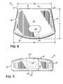
- FIG. 6is a bottom view of the implant shown in FIGS. 1-5 ;
- FIG. 7is a rear elevational view of the implant shown in FIGS. 1-6 .
- the present inventionis directed to skeletal implants and methods for placing implants between bones desired to be fused. It is preferred for the implants to be used for vertebral/spinal applications such as fusing cervical, thoracic and/or lumbar intervertebral joints. In the case of fusing an intervertebral joint, implants in accordance with the principles of the present invention can be implanted using an anterior, posterior or postero-lateral approach to the patient's vertebrae.
- an “implant”includes any implant suitable for facilitating fusion between adjacent bones and includes implants prepared from known implant materials including, non-bone material such as titanium, stainless steel, porous tantalum or other metal, bio-glass, calcium phosphate, ceramic, carbon fiber-based polymers and biodegradable polymers.
- FIGS. 1-7illustrate a spinal implant 10 according to one embodiment of the present invention.
- Implant 10includes a body 12 having a leading end 14 , a convex trailing end 16 and first 18 and second 20 sides that extend between the leading 14 and trailing 16 ends.
- Leading end 14may include rounded, or radiused portions, indicated at 21 , that blend with sides 18 , 20 .
- Leading end 14may be generally straight between the rounded portions 21 .
- the body 12further includes a generally dome-shaped superior surface 22 and an inferior surface 24 that may be generally flat.
- the superior surfaceis convex between the leading 14 and trailing 16 ends and is also convex between sides 18 , 20 . Accordingly, the superior surface is convex in both an anterior-to-posterior direction and a medial-to-lateral direction.
- Implant 10further includes an opening 26 that extends completely through implant 10 from the superior surface 22 to the inferior surface 24 .
- Implant 10also includes an opening 28 that communicates with opening 26 and extends through the trailing end 16 .
- the function of openings 26 , 28are described below.
- openings 26 and 28may be generally oval-shaped. However, one or both of openings 26 , 28 may have other shapes within the scope of the present invention.
- implant 10has a height “H.sub. 1 ” extending between the highest point on the superior surface 22 and the inferior surface 24 .
- Implant 10also includes length “L” that extends between the leading end 14 and the location on trailing end 16 that is the farthest away from leading end 14 .
- a first width “W.sub. 1 ”exists between sides 18 , 20 at the trailing end 16 and a second width “W.sub. 2 ” exists between sides 18 , 20 at the leading end 14 .
- Sides 18 and 20may diverge away from one another between the leading 14 and trailing 16 ends, as shown in FIGS. 2 and 6 .
- the inferior surface 24has a generally trapezoidal shape and width “W.sub. 1 ” is greater than width “W.sub. 2 ”.
- the magnitudes height “H”, length “L” and widths “W.sub. 1 ” and “W.sub. 2 ”may vary with application.
- implant 10may be inserted into a cervical disc space to fuse adjacent cervical vertebrae. Also, in an exemplary embodiment, implant 10 may be inserted using an anterior approach, such that leading end 14 is a posterior end and trailing end 16 is an anterior end. In this event, a distal end, or key of an instrument, such as an inserter (not shown) may be inserted into opening 28 such that a width of the key initially extends generally along a longitudinal axis 30 of opening 28 . When the inserter is inserted farther into implant 10 , the key of the inserter reaches the intersection of openings 26 and 28 . The inserter may then be rotated 90 degrees such that the width of the key extends along the length of opening 26 partially between the superior 22 and inferior 24 surfaces.
- an insertermay be rotated 90 degrees such that the width of the key extends along the length of opening 26 partially between the superior 22 and inferior 24 surfaces.
- the width of the inserter keyis sized such that it is greater than a height “H.sub. 2 ” of opening 28 , which releasably secures the inserter to implant 10 .
- the insertermay be removed by rotating it 90 degrees which generally aligns the width of the key with the longitudinal axis 30 of opening 28 , and then retracting the inserter from implant 10 .
- the generally trapezoidal shape of inferior surface 24when implant 10 is used to fuse adjacent cervical vertebrae, may match the general shape of cervical vertebral bodies.
- the dome-shaped superior surface 22may generally match cervical endplate anatomy and the generally flat inferior surface 24 may mate with a flat inferior endplate in the cervical disc space or a surgically-created flat surface of a vertebral body during a hemi-vertebrectomy.
- Body 10may be made from a metal, which may be a porous metal. The use of a porous metal enhances bony ingrowth.
- Trabecular MetalTMwhich is marketed by Zimmer Spine, Inc., of Edina, Minn. Embodiments of this material are also described in several U.S. patents, including, for example, U.S. Pat. Nos. 5,443,515 and 6,063,042, each disclosure of which is expressly incorporated by reference herein in its entirety.
- Implants 10may be inserted by a variety of surgical approaches, including, but not limited to an anterior approach, a lateral (transverse) approach, a posterior approach, or postero-lateral approach by engaging the implant 10 with an instrument, such as an inserter.
- an instrumentsuch as an inserter.
- openings 26 and 28may be used to receive an inserter.
- implant 10may include grooves, indentations, slots or other surface deficits that allow the inserter to engage implant 10 .
- the trailing end 16 of body 12 of implant 10may include holes, such as a circular hole or holes that mate with prongs on the inserter.
- body 12may include two or more square or rectangular surface deficits cut into the superior 22 and inferior 24 surfaces proximate trailing end 16 that may be engaged by the inserter.
- slots or groovesmay be formed in each of the sides 18 , 20 .
- the slots or groovesmay be partially formed into and engaged at the trailing end 16 by the inserter.
- the slots or groovesmay be formed such that a portion of the implant 10 forms a positive stop for the inserter instrument.
- the slots or groovesmay extend the length of the sides 18 , 20 of body 12 .
Landscapes
- Health & Medical Sciences (AREA)
- Engineering & Computer Science (AREA)
- Biomedical Technology (AREA)
- Neurology (AREA)
- Orthopedic Medicine & Surgery (AREA)
- Cardiology (AREA)
- Oral & Maxillofacial Surgery (AREA)
- Transplantation (AREA)
- Heart & Thoracic Surgery (AREA)
- Vascular Medicine (AREA)
- Life Sciences & Earth Sciences (AREA)
- Animal Behavior & Ethology (AREA)
- General Health & Medical Sciences (AREA)
- Public Health (AREA)
- Veterinary Medicine (AREA)
- Prostheses (AREA)
Abstract
Description
Claims (20)
Priority Applications (1)
| Application Number | Priority Date | Filing Date | Title |
|---|---|---|---|
| US13/479,778US8568484B2 (en) | 2007-02-19 | 2012-05-24 | Spinal implant |
Applications Claiming Priority (3)
| Application Number | Priority Date | Filing Date | Title |
|---|---|---|---|
| US29/277,225USD566842S1 (en) | 2007-02-19 | 2007-02-19 | Spinal implant |
| US11/770,087US8192492B2 (en) | 2007-02-19 | 2007-06-28 | Spinal implant |
| US13/479,778US8568484B2 (en) | 2007-02-19 | 2012-05-24 | Spinal implant |
Related Parent Applications (1)
| Application Number | Title | Priority Date | Filing Date |
|---|---|---|---|
| US11/770,087ContinuationUS8192492B2 (en) | 2007-02-19 | 2007-06-28 | Spinal implant |
Publications (2)
| Publication Number | Publication Date |
|---|---|
| US20120303123A1 US20120303123A1 (en) | 2012-11-29 |
| US8568484B2true US8568484B2 (en) | 2013-10-29 |
Family
ID=39282228
Family Applications (3)
| Application Number | Title | Priority Date | Filing Date |
|---|---|---|---|
| US29/277,225Expired - LifetimeUSD566842S1 (en) | 2007-02-19 | 2007-02-19 | Spinal implant |
| US11/770,087Expired - Fee RelatedUS8192492B2 (en) | 2007-02-19 | 2007-06-28 | Spinal implant |
| US13/479,778ActiveUS8568484B2 (en) | 2007-02-19 | 2012-05-24 | Spinal implant |
Family Applications Before (2)
| Application Number | Title | Priority Date | Filing Date |
|---|---|---|---|
| US29/277,225Expired - LifetimeUSD566842S1 (en) | 2007-02-19 | 2007-02-19 | Spinal implant |
| US11/770,087Expired - Fee RelatedUS8192492B2 (en) | 2007-02-19 | 2007-06-28 | Spinal implant |
Country Status (1)
| Country | Link |
|---|---|
| US (3) | USD566842S1 (en) |
Cited By (3)
| Publication number | Priority date | Publication date | Assignee | Title |
|---|---|---|---|---|
| US20140336772A1 (en)* | 1998-06-30 | 2014-11-13 | Bonutti Skeletal Innovations Llc | Method and apparatus for use in operating on a bone |
| US20150088201A1 (en)* | 2011-02-23 | 2015-03-26 | Farzad Massoudi | Spinal implant device with fusion cage and fixation plates and method of implanting |
| US9044341B2 (en) | 1998-08-20 | 2015-06-02 | Bonutti Skeletal Innovations Llc | Joint spacer |
Families Citing this family (15)
| Publication number | Priority date | Publication date | Assignee | Title |
|---|---|---|---|---|
| USD597674S1 (en)* | 2004-10-21 | 2009-08-04 | Disc Motion Technologies, Inc. | Concave intervertebral disc prosthesis |
| USD598105S1 (en)* | 2004-10-21 | 2009-08-11 | Disc Motion Technologies, Inc. | Convex intervertebral disc prosthesis |
| USD580552S1 (en)* | 2007-02-19 | 2008-11-11 | Zimmer Spine, Inc. | Spinal implant |
| JP2012500058A (en)* | 2008-08-13 | 2012-01-05 | スメド−ティーエイ/ティーディー・エルエルシー | Orthopedic implant with a porous structural member |
| US9700431B2 (en)* | 2008-08-13 | 2017-07-11 | Smed-Ta/Td, Llc | Orthopaedic implant with porous structural member |
| US20100042213A1 (en) | 2008-08-13 | 2010-02-18 | Nebosky Paul S | Drug delivery implants |
| US10842645B2 (en) | 2008-08-13 | 2020-11-24 | Smed-Ta/Td, Llc | Orthopaedic implant with porous structural member |
| US9616205B2 (en) | 2008-08-13 | 2017-04-11 | Smed-Ta/Td, Llc | Drug delivery implants |
| WO2010025386A1 (en) | 2008-08-29 | 2010-03-04 | Smed-Ta/Td, Llc | Orthopaedic implant |
| USD606195S1 (en)* | 2008-09-04 | 2009-12-15 | Paradigm Spine, Llc | Interspinous implant |
| US9132021B2 (en) | 2011-10-07 | 2015-09-15 | Pioneer Surgical Technology, Inc. | Intervertebral implant |
| CN107569306B (en)* | 2016-07-04 | 2020-10-09 | 重庆润泽医药有限公司 | Spinal implant |
| WO2019051260A1 (en) | 2017-09-08 | 2019-03-14 | Pioneer Surgical Technology, Inc. | Intervertebral implants, instruments, and methods |
| USD907771S1 (en) | 2017-10-09 | 2021-01-12 | Pioneer Surgical Technology, Inc. | Intervertebral implant |
| US11452618B2 (en) | 2019-09-23 | 2022-09-27 | Dimicron, Inc | Spinal artificial disc removal tool |
Citations (61)
| Publication number | Priority date | Publication date | Assignee | Title |
|---|---|---|---|---|
| US229175A (en) | 1880-06-22 | Nut-lock | ||
| USD283831S (en) | 1983-07-05 | 1986-05-13 | Maddock Mitchell E | Additive liquid metering device |
| US5192327A (en)* | 1991-03-22 | 1993-03-09 | Brantigan John W | Surgical prosthetic implant for vertebrae |
| US5306309A (en) | 1992-05-04 | 1994-04-26 | Calcitek, Inc. | Spinal disk implant and implantation kit |
| US5522899A (en) | 1988-06-28 | 1996-06-04 | Sofamor Danek Properties, Inc. | Artificial spinal fusion implants |
| US5534028A (en) | 1993-04-20 | 1996-07-09 | Howmedica, Inc. | Hydrogel intervertebral disc nucleus with diminished lateral bulging |
| USD377527S (en) | 1994-06-03 | 1997-01-21 | Sofamor Danek Group, Inc. | Artificial spinal infusion implant |
| US5607424A (en)* | 1995-04-10 | 1997-03-04 | Tropiano; Patrick | Domed cage |
| US5810825A (en) | 1995-06-01 | 1998-09-22 | Huebner; Randall J. | Surgical wire clamp |
| WO1999009914A1 (en) | 1997-08-27 | 1999-03-04 | University Of Florida Tissue Bank, Inc. | Cortical bone cervical smith-robinson fusion implant |
| US5888222A (en) | 1995-10-16 | 1999-03-30 | Sdgi Holding, Inc. | Intervertebral spacers |
| US5989289A (en) | 1995-10-16 | 1999-11-23 | Sdgi Holdings, Inc. | Bone grafts |
| WO2000007528A1 (en) | 1998-08-06 | 2000-02-17 | Sdgi Holdings, Inc. | Composited intervertebral bone spacers |
| US6066175A (en)* | 1993-02-16 | 2000-05-23 | Henderson; Fraser C. | Fusion stabilization chamber |
| US6096080A (en) | 1998-05-06 | 2000-08-01 | Cortek, Inc. | Apparatus for spinal fusion using implanted devices |
| US6143033A (en) | 1998-01-30 | 2000-11-07 | Synthes (Usa) | Allogenic intervertebral implant |
| USD433750S (en) | 1998-04-07 | 2000-11-14 | Pfizer Inc | Pharmaceutical tablet |
| US6245108B1 (en)* | 1999-02-25 | 2001-06-12 | Spineco | Spinal fusion implant |
| US6371988B1 (en) | 1996-10-23 | 2002-04-16 | Sdgi Holdings, Inc. | Bone grafts |
| US6423095B1 (en) | 1995-10-16 | 2002-07-23 | Sdgi Holdings, Inc. | Intervertebral spacers |
| US6425920B1 (en) | 1999-10-13 | 2002-07-30 | James S. Hamada | Spinal fusion implant |
| US20020106393A1 (en) | 2000-02-10 | 2002-08-08 | Bianchi John R. | Assembled implant, including mixed-composition segment |
| US6447544B1 (en) | 1995-06-07 | 2002-09-10 | Gary Karlin Michelson | Lordotic interbody spinal fusion implants |
| US6458159B1 (en) | 2000-08-15 | 2002-10-01 | John S. Thalgott | Disc prosthesis |
| US6468311B2 (en) | 2001-01-22 | 2002-10-22 | Sdgi Holdings, Inc. | Modular interbody fusion implant |
| WO2002091909A2 (en) | 1999-10-21 | 2002-11-21 | Sdgi Holdings, Inc | Devices and techniques for a posterior lateral disc space approach |
| US6503279B1 (en) | 1996-09-04 | 2003-01-07 | Synthes (Usa) | Intervertebral implant |
| US20030023306A1 (en) | 2000-03-14 | 2003-01-30 | Mingyan Liu | Vertebral implant for promoting arthrodesis of the spine |
| US6520993B2 (en) | 2000-12-29 | 2003-02-18 | Depuy Acromed, Inc. | Spinal implant |
| USD472972S1 (en) | 2000-10-27 | 2003-04-08 | Lifenet | Bone implant |
| US20030109928A1 (en)* | 2000-07-12 | 2003-06-12 | Denis Pasquet | Intersomatic implant |
| US20030125739A1 (en) | 2001-12-12 | 2003-07-03 | Bagga Charanpreet S. | Bioactive spinal implants and method of manufacture thereof |
| US20030153975A1 (en)* | 2002-02-12 | 2003-08-14 | Byrd John Abbott | Vertebral Interbody cage with translatable locking screw |
| US6638310B2 (en) | 2000-07-26 | 2003-10-28 | Osteotech, Inc. | Intervertebral spacer and implant insertion instrumentation |
| US20040068320A1 (en) | 2002-10-04 | 2004-04-08 | Robie Bruce H. | Prosthetic disc and vertebral body replacement device having pyrolytic carbon bearing members |
| US20040082999A1 (en)* | 2001-01-30 | 2004-04-29 | Robert Mathys | Bone implant, in particular, an inter-vertebral implant |
| US6746484B1 (en) | 1997-08-26 | 2004-06-08 | Society De Fabrication De Materiel De Orthopedique, S.A. | Spinal implant |
| US6749636B2 (en) | 2001-04-02 | 2004-06-15 | Gary K. Michelson | Contoured spinal fusion implants made of bone or a bone composite material |
| US20040117020A1 (en)* | 1999-10-21 | 2004-06-17 | George Frey | Devices and techniques for a posterior lateral disc space approach |
| US20040127990A1 (en)* | 2002-12-31 | 2004-07-01 | Bartish, Charles M. | Novel banana cage |
| US20040133279A1 (en) | 2003-01-06 | 2004-07-08 | Krueger David J. | Surgical implants for use as spinal spacers |
| US20040158324A1 (en)* | 2001-02-27 | 2004-08-12 | Robert Lange | Medical implant |
| US20040186572A1 (en)* | 2002-12-19 | 2004-09-23 | Co-Linge Ag | Pair of lumbar interbody implants and method of fusing together adjoining vertebrae bodies |
| US6800093B2 (en) | 1998-05-06 | 2004-10-05 | Cortek, Inc. | Device for spinal fusion |
| US20040199251A1 (en) | 2003-04-01 | 2004-10-07 | Sdgi Holdings, Inc. | Interbody fusion device |
| USD497993S1 (en) | 2003-07-22 | 2004-11-02 | Robert A. Dixon | Bioabsorbable structural interbody vertebral implant |
| US20050119753A1 (en) | 2000-02-22 | 2005-06-02 | Sdgi Holdings, Inc. | Anterior impacted bone graft and driver instruments |
| US20050149188A1 (en) | 2002-02-07 | 2005-07-07 | Cook Stephen D. | Anterior spinal implant |
| US20050171606A1 (en) | 2000-06-13 | 2005-08-04 | Michelson Gary K. | Method for installation of manufactured implants shaped to conform to a prepared implantation space |
| US20050222682A1 (en) | 2004-04-01 | 2005-10-06 | Cervitech, Inc. | Cervical intervertebral prosthesis |
| US20050240267A1 (en) | 2004-03-26 | 2005-10-27 | Randall Brandon L | Allograft implant |
| US20050251257A1 (en) | 2004-05-04 | 2005-11-10 | Mitchell Margaret E | Spinal implants with body and insert |
| US6964687B1 (en) | 1999-07-09 | 2005-11-15 | Scient'x | Anatomical interbody implant and gripper for same |
| US20060100705A1 (en) | 2004-11-10 | 2006-05-11 | Rolando Puno | Intervertebral spacer |
| US20060190082A1 (en) | 2002-03-12 | 2006-08-24 | Cervitech, Inc. | Intervertebral prosthesis system, in particular for the cervical spine |
| US20060241763A1 (en) | 1998-08-03 | 2006-10-26 | Synthes (Usa) | Multipiece bone implant |
| US20060247772A1 (en) | 2005-04-29 | 2006-11-02 | Mckay William F | Synthetic loadbearing collagen-mineral composites useful for spinal implants, and methods of manufacture |
| USD553742S1 (en) | 2006-03-24 | 2007-10-23 | Paceco Corp. | Anterior lumbar interbody fusion implant |
| US7435261B1 (en)* | 2005-03-24 | 2008-10-14 | Frank Castro | Spinal implant and method of using spinal implant |
| US20090093883A1 (en)* | 2007-10-05 | 2009-04-09 | Mauricio Rodolfo Carrasco | Interspinous implant |
| US20100152853A1 (en)* | 2008-12-17 | 2010-06-17 | X-Spine Systems, Inc. | Prosthetic implant with biplanar angulation and compound angles |
- 2007
- 2007-02-19USUS29/277,225patent/USD566842S1/ennot_activeExpired - Lifetime
- 2007-06-28USUS11/770,087patent/US8192492B2/ennot_activeExpired - Fee Related
- 2012
- 2012-05-24USUS13/479,778patent/US8568484B2/enactiveActive
Patent Citations (70)
| Publication number | Priority date | Publication date | Assignee | Title |
|---|---|---|---|---|
| US229175A (en) | 1880-06-22 | Nut-lock | ||
| USD283831S (en) | 1983-07-05 | 1986-05-13 | Maddock Mitchell E | Additive liquid metering device |
| US5776199A (en) | 1988-06-28 | 1998-07-07 | Sofamor Danek Properties | Artificial spinal fusion implants |
| US5522899A (en) | 1988-06-28 | 1996-06-04 | Sofamor Danek Properties, Inc. | Artificial spinal fusion implants |
| US6733535B2 (en) | 1988-06-28 | 2004-05-11 | Sdgi Holdings, Inc. | Spinal fusion implant having a trailing end adapted to engage an insertion device |
| US5192327A (en)* | 1991-03-22 | 1993-03-09 | Brantigan John W | Surgical prosthetic implant for vertebrae |
| US5306309A (en) | 1992-05-04 | 1994-04-26 | Calcitek, Inc. | Spinal disk implant and implantation kit |
| US6066175A (en)* | 1993-02-16 | 2000-05-23 | Henderson; Fraser C. | Fusion stabilization chamber |
| US5534028A (en) | 1993-04-20 | 1996-07-09 | Howmedica, Inc. | Hydrogel intervertebral disc nucleus with diminished lateral bulging |
| USD377527S (en) | 1994-06-03 | 1997-01-21 | Sofamor Danek Group, Inc. | Artificial spinal infusion implant |
| US5607424A (en)* | 1995-04-10 | 1997-03-04 | Tropiano; Patrick | Domed cage |
| US5810825A (en) | 1995-06-01 | 1998-09-22 | Huebner; Randall J. | Surgical wire clamp |
| US6447544B1 (en) | 1995-06-07 | 2002-09-10 | Gary Karlin Michelson | Lordotic interbody spinal fusion implants |
| US5989289A (en) | 1995-10-16 | 1999-11-23 | Sdgi Holdings, Inc. | Bone grafts |
| US20050004672A1 (en) | 1995-10-16 | 2005-01-06 | John Pafford | Bone grafts |
| US5888222A (en) | 1995-10-16 | 1999-03-30 | Sdgi Holding, Inc. | Intervertebral spacers |
| US20040230306A1 (en) | 1995-10-16 | 2004-11-18 | Hoeck James E. Van | Intervertebral spacers |
| US6423095B1 (en) | 1995-10-16 | 2002-07-23 | Sdgi Holdings, Inc. | Intervertebral spacers |
| US6503279B1 (en) | 1996-09-04 | 2003-01-07 | Synthes (Usa) | Intervertebral implant |
| US6371988B1 (en) | 1996-10-23 | 2002-04-16 | Sdgi Holdings, Inc. | Bone grafts |
| US6746484B1 (en) | 1997-08-26 | 2004-06-08 | Society De Fabrication De Materiel De Orthopedique, S.A. | Spinal implant |
| US7048765B1 (en) | 1997-08-27 | 2006-05-23 | Regeneration Technologies, Inc. | Intervertebral spacers |
| WO1999009914A1 (en) | 1997-08-27 | 1999-03-04 | University Of Florida Tissue Bank, Inc. | Cortical bone cervical smith-robinson fusion implant |
| US6143033A (en) | 1998-01-30 | 2000-11-07 | Synthes (Usa) | Allogenic intervertebral implant |
| USD433750S (en) | 1998-04-07 | 2000-11-14 | Pfizer Inc | Pharmaceutical tablet |
| US6096080A (en) | 1998-05-06 | 2000-08-01 | Cortek, Inc. | Apparatus for spinal fusion using implanted devices |
| US6800093B2 (en) | 1998-05-06 | 2004-10-05 | Cortek, Inc. | Device for spinal fusion |
| US20060241763A1 (en) | 1998-08-03 | 2006-10-26 | Synthes (Usa) | Multipiece bone implant |
| WO2000007528A1 (en) | 1998-08-06 | 2000-02-17 | Sdgi Holdings, Inc. | Composited intervertebral bone spacers |
| US6245108B1 (en)* | 1999-02-25 | 2001-06-12 | Spineco | Spinal fusion implant |
| US6964687B1 (en) | 1999-07-09 | 2005-11-15 | Scient'x | Anatomical interbody implant and gripper for same |
| US6425920B1 (en) | 1999-10-13 | 2002-07-30 | James S. Hamada | Spinal fusion implant |
| WO2002091909A2 (en) | 1999-10-21 | 2002-11-21 | Sdgi Holdings, Inc | Devices and techniques for a posterior lateral disc space approach |
| US20040117020A1 (en)* | 1999-10-21 | 2004-06-17 | George Frey | Devices and techniques for a posterior lateral disc space approach |
| WO2002091909A3 (en) | 1999-10-21 | 2003-08-14 | Sdgi Holdings Inc | Devices and techniques for a posterior lateral disc space approach |
| US20020106393A1 (en) | 2000-02-10 | 2002-08-08 | Bianchi John R. | Assembled implant, including mixed-composition segment |
| US20050119753A1 (en) | 2000-02-22 | 2005-06-02 | Sdgi Holdings, Inc. | Anterior impacted bone graft and driver instruments |
| US20030023306A1 (en) | 2000-03-14 | 2003-01-30 | Mingyan Liu | Vertebral implant for promoting arthrodesis of the spine |
| US20050171606A1 (en) | 2000-06-13 | 2005-08-04 | Michelson Gary K. | Method for installation of manufactured implants shaped to conform to a prepared implantation space |
| US20030109928A1 (en)* | 2000-07-12 | 2003-06-12 | Denis Pasquet | Intersomatic implant |
| US6638310B2 (en) | 2000-07-26 | 2003-10-28 | Osteotech, Inc. | Intervertebral spacer and implant insertion instrumentation |
| US6458159B1 (en) | 2000-08-15 | 2002-10-01 | John S. Thalgott | Disc prosthesis |
| USD472972S1 (en) | 2000-10-27 | 2003-04-08 | Lifenet | Bone implant |
| US6520993B2 (en) | 2000-12-29 | 2003-02-18 | Depuy Acromed, Inc. | Spinal implant |
| US6468311B2 (en) | 2001-01-22 | 2002-10-22 | Sdgi Holdings, Inc. | Modular interbody fusion implant |
| US20040082999A1 (en)* | 2001-01-30 | 2004-04-29 | Robert Mathys | Bone implant, in particular, an inter-vertebral implant |
| US20040158324A1 (en)* | 2001-02-27 | 2004-08-12 | Robert Lange | Medical implant |
| US20040230308A1 (en) | 2001-04-02 | 2004-11-18 | Michelson Gary K. | Contoured cortical bone implants |
| US6749636B2 (en) | 2001-04-02 | 2004-06-15 | Gary K. Michelson | Contoured spinal fusion implants made of bone or a bone composite material |
| US20030125739A1 (en) | 2001-12-12 | 2003-07-03 | Bagga Charanpreet S. | Bioactive spinal implants and method of manufacture thereof |
| US7238203B2 (en) | 2001-12-12 | 2007-07-03 | Vita Special Purpose Corporation | Bioactive spinal implants and method of manufacture thereof |
| US20050149188A1 (en) | 2002-02-07 | 2005-07-07 | Cook Stephen D. | Anterior spinal implant |
| US20030153975A1 (en)* | 2002-02-12 | 2003-08-14 | Byrd John Abbott | Vertebral Interbody cage with translatable locking screw |
| US20060190082A1 (en) | 2002-03-12 | 2006-08-24 | Cervitech, Inc. | Intervertebral prosthesis system, in particular for the cervical spine |
| US7749272B2 (en) | 2002-10-04 | 2010-07-06 | Zimmer Trabecular Metal Technology, Inc. | Prosthetic disc and vertebral body replacement device having pyrolytic carbon bearing members |
| US20040068320A1 (en) | 2002-10-04 | 2004-04-08 | Robie Bruce H. | Prosthetic disc and vertebral body replacement device having pyrolytic carbon bearing members |
| US20040186572A1 (en)* | 2002-12-19 | 2004-09-23 | Co-Linge Ag | Pair of lumbar interbody implants and method of fusing together adjoining vertebrae bodies |
| US20040127990A1 (en)* | 2002-12-31 | 2004-07-01 | Bartish, Charles M. | Novel banana cage |
| US20040133279A1 (en) | 2003-01-06 | 2004-07-08 | Krueger David J. | Surgical implants for use as spinal spacers |
| US20040199251A1 (en) | 2003-04-01 | 2004-10-07 | Sdgi Holdings, Inc. | Interbody fusion device |
| USD497993S1 (en) | 2003-07-22 | 2004-11-02 | Robert A. Dixon | Bioabsorbable structural interbody vertebral implant |
| US20050240267A1 (en) | 2004-03-26 | 2005-10-27 | Randall Brandon L | Allograft implant |
| US20050222682A1 (en) | 2004-04-01 | 2005-10-06 | Cervitech, Inc. | Cervical intervertebral prosthesis |
| US20050251257A1 (en) | 2004-05-04 | 2005-11-10 | Mitchell Margaret E | Spinal implants with body and insert |
| US20060100705A1 (en) | 2004-11-10 | 2006-05-11 | Rolando Puno | Intervertebral spacer |
| US7435261B1 (en)* | 2005-03-24 | 2008-10-14 | Frank Castro | Spinal implant and method of using spinal implant |
| US20060247772A1 (en) | 2005-04-29 | 2006-11-02 | Mckay William F | Synthetic loadbearing collagen-mineral composites useful for spinal implants, and methods of manufacture |
| USD553742S1 (en) | 2006-03-24 | 2007-10-23 | Paceco Corp. | Anterior lumbar interbody fusion implant |
| US20090093883A1 (en)* | 2007-10-05 | 2009-04-09 | Mauricio Rodolfo Carrasco | Interspinous implant |
| US20100152853A1 (en)* | 2008-12-17 | 2010-06-17 | X-Spine Systems, Inc. | Prosthetic implant with biplanar angulation and compound angles |
Cited By (7)
| Publication number | Priority date | Publication date | Assignee | Title |
|---|---|---|---|---|
| US20140336772A1 (en)* | 1998-06-30 | 2014-11-13 | Bonutti Skeletal Innovations Llc | Method and apparatus for use in operating on a bone |
| US9044322B2 (en)* | 1998-06-30 | 2015-06-02 | Bonutti Skeletal Innovations Llc | Method and apparatus for use in operating on a bone |
| US9050152B2 (en) | 1998-06-30 | 2015-06-09 | Bonutti Skeletal Innovations Llc | Method and apparatus for use in operating on a bone |
| US9044341B2 (en) | 1998-08-20 | 2015-06-02 | Bonutti Skeletal Innovations Llc | Joint spacer |
| US20150088201A1 (en)* | 2011-02-23 | 2015-03-26 | Farzad Massoudi | Spinal implant device with fusion cage and fixation plates and method of implanting |
| US20170035466A1 (en)* | 2011-02-23 | 2017-02-09 | Farzad Massoudi | Method for implanting spinal implant device with fusion cage |
| US10052138B2 (en)* | 2011-02-23 | 2018-08-21 | Farzad Massoudi | Method for implanting spinal implant device with fusion cage |
Also Published As
| Publication number | Publication date |
|---|---|
| US20080200985A1 (en) | 2008-08-21 |
| USD566842S1 (en) | 2008-04-15 |
| US20120303123A1 (en) | 2012-11-29 |
| US8192492B2 (en) | 2012-06-05 |
Similar Documents
| Publication | Publication Date | Title |
|---|---|---|
| US8568484B2 (en) | Spinal implant | |
| US20220273459A1 (en) | Method and spacer device for spanning a space formed upon removal of an intervertebral disc | |
| US10512548B2 (en) | Intervertebral implant with fixation geometry | |
| US20080208342A1 (en) | Spinal implant | |
| US10993813B2 (en) | Prosthetic spinal disc replacement and methods thereof | |
| US8002831B2 (en) | Modular lateral expansion device | |
| US7137997B2 (en) | Spinal fusion implant | |
| US20040230307A1 (en) | Device for fusing two bone segments | |
| US7887588B2 (en) | Interbody spinal fusion device | |
| US20080188940A1 (en) | Spinal Implant | |
| US20040199251A1 (en) | Interbody fusion device | |
| US20120158143A1 (en) | ALIF Spinal Cage | |
| US20240238095A1 (en) | Spinal implant with surface projections | |
| AU2022304563A1 (en) | Bellows shaped spinal implant | |
| EP1596772B1 (en) | Device for fusing two bone segments | |
| JP6596026B2 (en) | Artificial spinal disc replacement and method |
Legal Events
| Date | Code | Title | Description |
|---|---|---|---|
| STCF | Information on status: patent grant | Free format text:PATENTED CASE | |
| FPAY | Fee payment | Year of fee payment:4 | |
| MAFP | Maintenance fee payment | Free format text:PAYMENT OF MAINTENANCE FEE, 8TH YEAR, LARGE ENTITY (ORIGINAL EVENT CODE: M1552); ENTITY STATUS OF PATENT OWNER: LARGE ENTITY Year of fee payment:8 | |
| AS | Assignment | Owner name:ZIMMER BIOMET SPINE, INC., INDIANA Free format text:MERGER;ASSIGNOR:ZIMMER SPINE, INC.;REEL/FRAME:059232/0356 Effective date:20160930 | |
| AS | Assignment | Owner name:JPMORGAN CHASE BANK, N.A., AS ADMINISTRATIVE AGENT, NEW YORK Free format text:SECURITY INTEREST;ASSIGNORS:BIOMET 3I, LLC;EBI, LLC;ZIMMER BIOMET SPINE, INC.;AND OTHERS;REEL/FRAME:059293/0213 Effective date:20220228 | |
| AS | Assignment | Owner name:CERBERUS BUSINESS FINANCE AGENCY, LLC, NEW YORK Free format text:GRANT OF A SECURITY INTEREST -- PATENTS;ASSIGNORS:ZIMMER BIOMET SPINE, LLC;EBI, LLC;REEL/FRAME:066970/0806 Effective date:20240401 | |
| AS | Assignment | Owner name:ZIMMER BIOMET SPINE, LLC (F/K/A ZIMMER BIOMET SPINE, INC.), COLORADO Free format text:RELEASE BY SECURED PARTY;ASSIGNOR:JPMORGAN CHASE BANK, N.A.;REEL/FRAME:066973/0833 Effective date:20240401 Owner name:EBI, LLC, NEW JERSEY Free format text:RELEASE BY SECURED PARTY;ASSIGNOR:JPMORGAN CHASE BANK, N.A.;REEL/FRAME:066973/0833 Effective date:20240401 | |
| AS | Assignment | Owner name:ZIMMER BIOMET SPINE, LLC, COLORADO Free format text:CHANGE OF NAME;ASSIGNOR:ZIMMER BIOMET SPINE, INC.;REEL/FRAME:069772/0121 Effective date:20240220 Owner name:HIGHRIDGE MEDICAL, LLC, COLORADO Free format text:CHANGE OF NAME;ASSIGNOR:ZIMMER BIOMET SPINE, LLC;REEL/FRAME:069772/0248 Effective date:20240405 | |
| FEPP | Fee payment procedure | Free format text:MAINTENANCE FEE REMINDER MAILED (ORIGINAL EVENT CODE: REM.); ENTITY STATUS OF PATENT OWNER: LARGE ENTITY |