US8568413B2 - Bone fixation device, tools and methods - Google Patents
Bone fixation device, tools and methodsDownload PDFInfo
- Publication number
- US8568413B2 US8568413B2US12/642,648US64264809AUS8568413B2US 8568413 B2US8568413 B2US 8568413B2US 64264809 AUS64264809 AUS 64264809AUS 8568413 B2US8568413 B2US 8568413B2
- Authority
- US
- United States
- Prior art keywords
- hub
- bone
- fixation device
- bone fixation
- screw
- Prior art date
- Legal status (The legal status is an assumption and is not a legal conclusion. Google has not performed a legal analysis and makes no representation as to the accuracy of the status listed.)
- Expired - Fee Related, expires
Links
- 210000000988bone and boneAnatomy0.000titleclaimsabstractdescription259
- 238000000034methodMethods0.000titleabstractdescription49
- 239000000463materialSubstances0.000claimsdescription20
- 238000005452bendingMethods0.000claimsdescription9
- 230000000670limiting effectEffects0.000claimsdescription3
- 229910003460diamondInorganic materials0.000claimsdescription2
- 239000010432diamondSubstances0.000claimsdescription2
- 238000013461designMethods0.000abstractdescription7
- 208000010392Bone FracturesDiseases0.000description59
- 206010017076FractureDiseases0.000description51
- 239000002131composite materialSubstances0.000description14
- 208000001132OsteoporosisDiseases0.000description10
- 238000003780insertionMethods0.000description9
- 230000037431insertionEffects0.000description9
- 230000002787reinforcementEffects0.000description9
- 238000010276constructionMethods0.000description8
- 238000001727in vivoMethods0.000description8
- 210000002320radiusAnatomy0.000description8
- 230000001054cortical effectEffects0.000description7
- 229920000642polymerPolymers0.000description7
- 238000004519manufacturing processMethods0.000description6
- 229910001000nickel titaniumInorganic materials0.000description6
- 210000003484anatomyAnatomy0.000description5
- 230000015572biosynthetic processEffects0.000description5
- 238000005553drillingMethods0.000description5
- 230000013011matingEffects0.000description5
- 238000002844meltingMethods0.000description5
- 230000008018meltingEffects0.000description5
- 229910052751metalInorganic materials0.000description5
- 239000002184metalSubstances0.000description5
- 210000002346musculoskeletal systemAnatomy0.000description5
- 230000008569processEffects0.000description5
- 230000008439repair processEffects0.000description5
- 238000001356surgical procedureMethods0.000description5
- 241001465754MetazoaSpecies0.000description4
- 229910000831SteelInorganic materials0.000description4
- RTAQQCXQSZGOHL-UHFFFAOYSA-NTitaniumChemical compound[Ti]RTAQQCXQSZGOHL-UHFFFAOYSA-N0.000description4
- 230000008901benefitEffects0.000description4
- 230000008859changeEffects0.000description4
- 238000009760electrical discharge machiningMethods0.000description4
- 238000010894electron beam technologyMethods0.000description4
- 238000005530etchingMethods0.000description4
- 239000012634fragmentSubstances0.000description4
- 229910052500inorganic mineralInorganic materials0.000description4
- 238000003698laser cuttingMethods0.000description4
- 230000007246mechanismEffects0.000description4
- 239000011707mineralSubstances0.000description4
- HLXZNVUGXRDIFK-UHFFFAOYSA-Nnickel titaniumChemical compound[Ti].[Ti].[Ti].[Ti].[Ti].[Ti].[Ti].[Ti].[Ti].[Ti].[Ti].[Ni].[Ni].[Ni].[Ni].[Ni].[Ni].[Ni].[Ni].[Ni].[Ni].[Ni].[Ni].[Ni].[Ni]HLXZNVUGXRDIFK-UHFFFAOYSA-N0.000description4
- 229920003229poly(methyl methacrylate)Polymers0.000description4
- 239000004926polymethyl methacrylateSubstances0.000description4
- 239000010959steelSubstances0.000description4
- 229910052719titaniumInorganic materials0.000description4
- 239000010936titaniumSubstances0.000description4
- 239000004696Poly ether ether ketoneSubstances0.000description3
- 238000013459approachMethods0.000description3
- 210000003109clavicleAnatomy0.000description3
- 210000003275diaphysisAnatomy0.000description3
- 210000002758humerusAnatomy0.000description3
- 208000015181infectious diseaseDiseases0.000description3
- 230000033001locomotionEffects0.000description3
- 201000008482osteoarthritisDiseases0.000description3
- 229920002530polyetherether ketonePolymers0.000description3
- 239000007787solidSubstances0.000description3
- 210000001519tissueAnatomy0.000description3
- 238000007514turningMethods0.000description3
- 210000000623ulnaAnatomy0.000description3
- 210000000689upper legAnatomy0.000description3
- 229910000684Cobalt-chromeInorganic materials0.000description2
- 102000008186CollagenHuman genes0.000description2
- 108010035532CollagenProteins0.000description2
- WAIPAZQMEIHHTJ-UHFFFAOYSA-N[Cr].[Co]Chemical compound[Cr].[Co]WAIPAZQMEIHHTJ-UHFFFAOYSA-N0.000description2
- 229910045601alloyInorganic materials0.000description2
- 239000000956alloySubstances0.000description2
- 238000004873anchoringMethods0.000description2
- 238000002725brachytherapyMethods0.000description2
- 239000010952cobalt-chromeSubstances0.000description2
- 229920001436collagenPolymers0.000description2
- 230000008878couplingEffects0.000description2
- 238000010168coupling processMethods0.000description2
- 238000005859coupling reactionMethods0.000description2
- 125000004122cyclic groupChemical group0.000description2
- 230000003247decreasing effectEffects0.000description2
- 239000003814drugSubstances0.000description2
- 210000002745epiphysisAnatomy0.000description2
- 210000002082fibulaAnatomy0.000description2
- 230000006870functionEffects0.000description2
- 239000003365glass fiberSubstances0.000description2
- 230000035876healingEffects0.000description2
- 239000007943implantSubstances0.000description2
- 238000011065in-situ storageMethods0.000description2
- 208000014674injuryDiseases0.000description2
- 239000010410layerSubstances0.000description2
- 230000005226mechanical processes and functionsEffects0.000description2
- 239000004033plasticSubstances0.000description2
- 229920003023plasticPolymers0.000description2
- 230000009993protective functionEffects0.000description2
- 102000004169proteins and genesHuman genes0.000description2
- 108090000623proteins and genesProteins0.000description2
- 230000002285radioactive effectEffects0.000description2
- 230000006641stabilisationEffects0.000description2
- 238000011105stabilizationMethods0.000description2
- 239000010935stainless steelSubstances0.000description2
- 229910001220stainless steelInorganic materials0.000description2
- 230000000638stimulationEffects0.000description2
- 229940124597therapeutic agentDrugs0.000description2
- 238000002560therapeutic procedureMethods0.000description2
- 210000002303tibiaAnatomy0.000description2
- 230000008733traumaEffects0.000description2
- 238000003466weldingMethods0.000description2
- OYPRJOBELJOOCE-UHFFFAOYSA-NCalciumChemical compound[Ca]OYPRJOBELJOOCE-UHFFFAOYSA-N0.000description1
- 208000024779Comminuted FracturesDiseases0.000description1
- 241000597800Gulella radiusSpecies0.000description1
- 241000282412HomoSpecies0.000description1
- 208000001164Osteoporotic FracturesDiseases0.000description1
- 229910019142PO4Inorganic materials0.000description1
- 208000027418Wounds and injuryDiseases0.000description1
- 238000004026adhesive bondingMethods0.000description1
- 230000032683agingEffects0.000description1
- 239000002639bone cementSubstances0.000description1
- 210000001185bone marrowAnatomy0.000description1
- 230000010072bone remodelingEffects0.000description1
- 230000024279bone resorptionEffects0.000description1
- 238000005219brazingMethods0.000description1
- 229910052791calciumInorganic materials0.000description1
- 239000011575calciumSubstances0.000description1
- 230000006835compressionEffects0.000description1
- 238000007906compressionMethods0.000description1
- 210000002808connective tissueAnatomy0.000description1
- 238000005520cutting processMethods0.000description1
- 238000011161developmentMethods0.000description1
- 230000018109developmental processEffects0.000description1
- 201000010099diseaseDiseases0.000description1
- 208000037265diseases, disorders, signs and symptomsDiseases0.000description1
- 230000009977dual effectEffects0.000description1
- 230000000694effectsEffects0.000description1
- 230000007613environmental effectEffects0.000description1
- 210000002615epidermisAnatomy0.000description1
- 238000000605extractionMethods0.000description1
- 239000004744fabricSubstances0.000description1
- 230000004927fusionEffects0.000description1
- 210000000527greater trochanterAnatomy0.000description1
- 229920001903high density polyethylenePolymers0.000description1
- 239000004700high-density polyethyleneSubstances0.000description1
- 238000010348incorporationMethods0.000description1
- 230000003993interactionEffects0.000description1
- 238000005304joiningMethods0.000description1
- 230000003137locomotive effectEffects0.000description1
- 230000007774longtermEffects0.000description1
- 210000003141lower extremityAnatomy0.000description1
- 210000004373mandibleAnatomy0.000description1
- 230000007102metabolic functionEffects0.000description1
- 210000001037metacarpusAnatomy0.000description1
- 238000003801millingMethods0.000description1
- 230000004079mineral homeostasisEffects0.000description1
- 230000003387muscularEffects0.000description1
- 230000017074necrotic cell deathEffects0.000description1
- 210000000056organAnatomy0.000description1
- 230000000399orthopedic effectEffects0.000description1
- 230000001009osteoporotic effectEffects0.000description1
- 230000000149penetrating effectEffects0.000description1
- 230000035515penetrationEffects0.000description1
- 239000010452phosphateSubstances0.000description1
- NBIIXXVUZAFLBC-UHFFFAOYSA-KphosphateChemical compound[O-]P([O-])([O-])=ONBIIXXVUZAFLBC-UHFFFAOYSA-K0.000description1
- 230000035479physiological effects, processes and functionsEffects0.000description1
- 229920003223poly(pyromellitimide-1,4-diphenyl ether)Polymers0.000description1
- 238000003825pressingMethods0.000description1
- 230000002829reductive effectEffects0.000description1
- 230000000717retained effectEffects0.000description1
- 230000002441reversible effectEffects0.000description1
- 210000001991scapulaAnatomy0.000description1
- 239000002356single layerSubstances0.000description1
- 210000003491skinAnatomy0.000description1
- 210000003625skullAnatomy0.000description1
- 238000005476solderingMethods0.000description1
- 230000000087stabilizing effectEffects0.000description1
- 210000001562sternumAnatomy0.000description1
- 230000035882stressEffects0.000description1
- 238000006467substitution reactionMethods0.000description1
- 210000000457tarsusAnatomy0.000description1
- 230000001225therapeutic effectEffects0.000description1
- 210000000115thoracic cavityAnatomy0.000description1
- 230000009466transformationEffects0.000description1
- 210000001364upper extremityAnatomy0.000description1
- 238000004804windingMethods0.000description1
Images


Classifications
- A—HUMAN NECESSITIES
- A61—MEDICAL OR VETERINARY SCIENCE; HYGIENE
- A61B—DIAGNOSIS; SURGERY; IDENTIFICATION
- A61B17/00—Surgical instruments, devices or methods
- A61B17/56—Surgical instruments or methods for treatment of bones or joints; Devices specially adapted therefor
- A61B17/58—Surgical instruments or methods for treatment of bones or joints; Devices specially adapted therefor for osteosynthesis, e.g. bone plates, screws or setting implements
- A61B17/68—Internal fixation devices, including fasteners and spinal fixators, even if a part thereof projects from the skin
- A61B17/72—Intramedullary devices, e.g. pins or nails
- A—HUMAN NECESSITIES
- A61—MEDICAL OR VETERINARY SCIENCE; HYGIENE
- A61B—DIAGNOSIS; SURGERY; IDENTIFICATION
- A61B17/00—Surgical instruments, devices or methods
- A61B17/56—Surgical instruments or methods for treatment of bones or joints; Devices specially adapted therefor
- A61B17/58—Surgical instruments or methods for treatment of bones or joints; Devices specially adapted therefor for osteosynthesis, e.g. bone plates, screws or setting implements
- A61B17/68—Internal fixation devices, including fasteners and spinal fixators, even if a part thereof projects from the skin
- A61B17/72—Intramedullary devices, e.g. pins or nails
- A61B17/7208—Flexible pins, e.g. ENDER pins
- A—HUMAN NECESSITIES
- A61—MEDICAL OR VETERINARY SCIENCE; HYGIENE
- A61B—DIAGNOSIS; SURGERY; IDENTIFICATION
- A61B17/00—Surgical instruments, devices or methods
- A61B17/56—Surgical instruments or methods for treatment of bones or joints; Devices specially adapted therefor
- A61B17/58—Surgical instruments or methods for treatment of bones or joints; Devices specially adapted therefor for osteosynthesis, e.g. bone plates, screws or setting implements
- A61B17/68—Internal fixation devices, including fasteners and spinal fixators, even if a part thereof projects from the skin
- A61B17/72—Intramedullary devices, e.g. pins or nails
- A61B17/7233—Intramedullary devices, e.g. pins or nails with special means of locking the nail to the bone
- A61B17/7258—Intramedullary devices, e.g. pins or nails with special means of locking the nail to the bone with laterally expanding parts, e.g. for gripping the bone
- A61B17/7266—Intramedullary devices, e.g. pins or nails with special means of locking the nail to the bone with laterally expanding parts, e.g. for gripping the bone with fingers moving radially outwardly
- A—HUMAN NECESSITIES
- A61—MEDICAL OR VETERINARY SCIENCE; HYGIENE
- A61B—DIAGNOSIS; SURGERY; IDENTIFICATION
- A61B17/00—Surgical instruments, devices or methods
- A61B17/16—Instruments for performing osteoclasis; Drills or chisels for bones; Trepans
- A61B17/17—Guides or aligning means for drills, mills, pins or wires
- A61B17/1725—Guides or aligning means for drills, mills, pins or wires for applying transverse screws or pins through intramedullary nails or pins
- A—HUMAN NECESSITIES
- A61—MEDICAL OR VETERINARY SCIENCE; HYGIENE
- A61B—DIAGNOSIS; SURGERY; IDENTIFICATION
- A61B17/00—Surgical instruments, devices or methods
- A61B17/56—Surgical instruments or methods for treatment of bones or joints; Devices specially adapted therefor
- A61B17/58—Surgical instruments or methods for treatment of bones or joints; Devices specially adapted therefor for osteosynthesis, e.g. bone plates, screws or setting implements
- A61B17/68—Internal fixation devices, including fasteners and spinal fixators, even if a part thereof projects from the skin
- A61B17/72—Intramedullary devices, e.g. pins or nails
- A61B17/7216—Intramedullary devices, e.g. pins or nails for bone lengthening or compression
- A61B17/7225—Intramedullary devices, e.g. pins or nails for bone lengthening or compression for bone compression
- A—HUMAN NECESSITIES
- A61—MEDICAL OR VETERINARY SCIENCE; HYGIENE
- A61B—DIAGNOSIS; SURGERY; IDENTIFICATION
- A61B17/00—Surgical instruments, devices or methods
- A61B17/56—Surgical instruments or methods for treatment of bones or joints; Devices specially adapted therefor
- A61B17/58—Surgical instruments or methods for treatment of bones or joints; Devices specially adapted therefor for osteosynthesis, e.g. bone plates, screws or setting implements
- A61B17/68—Internal fixation devices, including fasteners and spinal fixators, even if a part thereof projects from the skin
- A61B17/72—Intramedullary devices, e.g. pins or nails
- A61B17/7291—Intramedullary devices, e.g. pins or nails for small bones, e.g. in the foot, ankle, hand or wrist
- A—HUMAN NECESSITIES
- A61—MEDICAL OR VETERINARY SCIENCE; HYGIENE
- A61B—DIAGNOSIS; SURGERY; IDENTIFICATION
- A61B17/00—Surgical instruments, devices or methods
- A61B17/56—Surgical instruments or methods for treatment of bones or joints; Devices specially adapted therefor
- A61B17/58—Surgical instruments or methods for treatment of bones or joints; Devices specially adapted therefor for osteosynthesis, e.g. bone plates, screws or setting implements
- A61B17/68—Internal fixation devices, including fasteners and spinal fixators, even if a part thereof projects from the skin
- A61B17/84—Fasteners therefor or fasteners being internal fixation devices
- A61B17/86—Pins or screws or threaded wires; nuts therefor
Definitions
- the present inventionrelates to devices, tools and methods for providing reinforcement of bones. More specifically, the present invention relates to devices, tools and methods for providing reconstruction and reinforcement of bones, including diseased, osteoporotic and fractured bones.
- Bone fracturesare a common medical condition both in the young and old segments of the population.
- osteoporosishas become more of a significant medical concern in part due to the risk of osteoporotic fractures.
- Osteoporosis and osteoarthritisare among the most common conditions to affect the musculoskeletal system, as well as frequent causes of locomotor pain and disability. Osteoporosis can occur in both human and animal subjects (e.g. horses).
- Osteoporosis (OP) and osteoarthritis (OA)occur in a substantial portion of the human population over the age of fifty.
- One current treatment of bone fracturesincludes surgically resetting the fractured bone. After the surgical procedure, the fractured area of the body (i.e., where the fractured bone is located) is often placed in an external cast for an extended period of time to ensure that the fractured bone heals properly. This can take several months for the bone to heal and for the patient to remove the cast before resuming normal activities.
- an intramedullary (IM) rod or nailis used to align and stabilize the fracture.
- IMintramedullary
- a metal rodis placed inside a canal of a bone and fixed in place, typically at both ends. See, for example, FixionTM IM (Nail), www.disc-o-tech.com.
- This approachrequires incision, access to the canal, and placement of the IM nail. The nail can be subsequently removed or left in place.
- a conventional IM nail procedurerequires a similar, but possibly larger, opening to the space, a long metallic nail being placed across the fracture, and either subsequent removal, and or when the nail is not removed, a long term implant of the IM nail.
- the outer diameter of the IM nailmust be selected for the minimum inside diameter of the space.
- portions of the IM nailmay not be in contact with the canal. Further, micro-motion between the bone and the IM nail may cause pain or necrosis of the bone. In still other cases, infection can occur.
- the IM nailmay be removed after the fracture has healed. This requires a subsequent surgery with all of the complications and risks of a later intrusive procedure. In general, rigid IM rods or nails are difficult to insert, can damage the bone and require additional incisions for cross-screws to attach the rods or nails to the bone.
- IM nailsare inflatable. See, for example, Meta-Fix IM Nailing System, www.disc-o-tech.com. Such IM nails require inflating the rod with very high pressures, endangering the surrounding bone. Inflatable nails have many of the same drawbacks as the rigid IM nails described above.
- External fixationis another technique employed to repair fractures.
- a rodmay traverse the fracture site outside of the epidermis.
- the rodis attached to the bone with trans-dermal screws. If external fixation is used, the patient will have multiple incisions, screws, and trans-dermal infection paths. Furthermore, the external fixation is cosmetically intrusive, bulky, and prone to painful inadvertent manipulation by environmental conditions such as, for example, bumping into objects and laying on the device.
- the bone fixation devicemay include an elongate body with a longitudinal axis and having a flexible state and a rigid state.
- the devicefurther may include a plurality of grippers disposed at longitudinally-spaced locations along the elongated body, a rigid hub connected to the elongated body, and an actuator that is operably-connected to the grippers to deploy the grippers from a first shape to an expanded second shape.
- a bone fixation deviceis provided with an elongate body having a longitudinal axis and having a first state in which at least a portion of the body is flexible and a second state in which the body is generally rigid, an actuateable gripper disposed at a distal location on the elongated body, a hub located on a proximal end of the elongated body, and an actuator operably connected to the gripper to deploy the gripper from a retracted configuration to an expanded configuration.
- One such methodcomprises inserting a bone fixation device into an intramedullary space of the bone to place at least a portion of an elongate body of the fixation device in a flexible state on one side of the fracture and at least a portion of a hub on another side of the fracture, and operating an actuator to deploy at least one gripper of the fixation device to engage an inner surface of the intramedullary space to anchor the fixation device to the bone.
- One embodiment of the present inventionprovides a low weight to volume mechanical support for fixation, reinforcement and reconstruction of bone or other regions of the musculo-skeletal system in both humans and animals.
- the method of delivery of the deviceis another aspect of the invention.
- the method of delivery of the device in accordance with the various embodiments of the inventionreduces the trauma created during surgery, decreasing the risks associated with infection and thereby decreasing the recuperation time of the patient.
- the frameworkmay in one embodiment include an expandable and contractible structure to penult re-placement and removal of the reinforcement structure or framework.
- the mechanical supporting framework or devicemay be made from a variety of materials such as metal, composite, plastic or amorphous materials, which include, but are not limited to, steel, stainless steel, cobalt chromium plated steel, titanium, nickel titanium alloy (nitinol), superelastic alloy, and polymethylmethacrylate (PMMA).
- the devicemay also include other polymeric materials that are biocompatible and provide mechanical strength, that include polymeric material with ability to carry and delivery therapeutic agents, that include bioabsorbable properties, as well as composite materials and composite materials of titanium and polyetheretherketone (PEEKTM), composite materials of polymers and minerals, composite materials of polymers and glass fibers, composite materials of metal, polymer, and minerals.
- PEEKTMpolyetheretherketone
- each of the aforementioned types of devicemay further be coated with proteins from synthetic or animal source, or include collagen coated structures, and radioactive or brachytherapy materials.
- the construction of the supporting framework or devicemay include radio-opaque markers or components that assist in their location during and after placement in the bone or other region of the musculo-skeletal systems.
- the reinforcement devicemay, in one embodiment, be osteo incorporating, such that the reinforcement device may be integrated into the bone.
- a method of repairing a bone fracturecomprises: accessing a fracture along a length of a bone through a bony protuberance at an access point at an end of a bone; advancing a bone fixation device into a space through the access point at the end of the bone; bending a portion of the bone fixation device along its length to traverse the fracture; and locking the bone fixation device into place within the space of the bone.
- the methodcan also include the step of advancing an obturator through the bony protuberance and across the fracture prior to advancing the bone fixation device into the space.
- the step of anchoring the bone fixation device within the spacecan be included.
- An aspect of the inventiondiscloses a removable bone fixation device that uses a single port of insertion and has a single-end of remote actuation wherein a bone fixation device stabilizes bone after it has traversed the fracture.
- the bone fixation deviceis adapted to provide a single end in one area or location where the device initiates interaction with bone.
- the devicecan be deployed such that the device interacts with bone.
- Single portal insertion and single-end remote actuationenables the surgeon to insert and deploy the device, deactivate and remove the device, reduce bone fractures, displace or compress the bone, and lock the device in place.
- the single-end actuationenables the device to grip bone, compresses the rigidizable flexible body, permits axial, torsional and angular adjustments to its position during surgery, and releases the device from the bone during its removal procedure.
- a removable extractorcan be provided in some embodiments of the device to enable the device to be placed and extracted by deployment and remote actuation from a single end.
- the device of the inventioncan be adapted and configured to provide at least one rigidizable flexible body or sleeve. Further the body can be configured to be flexible in all angles and directions. The flexibility provided is in selective planes and angles in the Cartesian, polar, or cylindrical coordinate systems. Further, in some embodiments, the body is configured to have a remote actuation at a single end.
- the bodycan be configured to have apertures, windings, etc.
- the devicemay be configured to function with non-flexible bodies for use in bones that have a substantially straight segment or curved segments with a constant radius of curvature.
- Another aspect of the inventionincludes a bone fixation device in that has mechanical geometry that interacts with bone by a change in the size of at least one dimension of a Cartesian, polar, or spherical coordinate system.
- bioabsorbable materialscan be used in conjunction with the devices, for example by providing specific subcomponents of the device configured from bioabsorbable materials.
- a sleevecan be provided in some embodiments where the sleeve is removable, has deployment, remote actuation, and a single end.
- the sleevecan be adapted to provide a deployable interdigitation process or to provide an aperture along its length through which the deployable interdigitation process is adapted to engage bone.
- the deployable interdigitation processis further adapted to engage bone when actuated by the sleeve.
- the bone fixation devicefurther comprises a cantilever adapted to retain the deployable bone fixation device within the space.
- the sleevecan further be adapted to be expanded and collapsed within the space by a user.
- One end of the devicecan be configured to provide a blunt obturator surface adapted to advance into the bone.
- a guiding tipmay also be provided that facilitates guiding the device through the bone.
- the deployable bone fixation devicecan be adapted to receive external stimulation to provide therapy to the bone.
- the devicecan further be adapted to provide an integral stimulator which provides therapy to the bone.
- the devicecan be adapted to receive deliver therapeutic stimulation to the bone.
- the devices disclosed hereinmay be employed in various regions of the body, including: cranial, thoracic, lower extremities and upper extremities. Additionally, the devices are suitable for a variety of breaks including, metaphyseal and diaphyseal.
- the fracture fixation devices of various embodiments of the inventionare adapted to be inserted through an opening of a fractured bone, such as the radius (e.g., through a bony protuberance on a distal or proximal end or through the midshaft) into the intramedullary canal of the bone.
- the fixation devicehas two main components, one configured component for being disposed on the side of the fracture closest to the opening and one component configured for being disposed on the other side of the fracture from the opening so that the fixation device traverses the fracture.
- the device componentscooperate to align, fix and/or reduce the fracture so as to promote healing.
- the devicemay be removed from the bone after insertion (e.g., after the fracture has healed or for other reasons), or it may be left in the bone for an extended period of time or permanently.
- the fracture fixation devicehas one or more actuatable anchors or grippers on its proximal and/or distal ends. These anchors may be used to hold the fixation device to the bone while the bone heals.
- At least one component of the fracture fixation devicehas a substantially flexible state and a substantially rigid state. Once in place, deployment of the device also causes the components to change from the flexible state to a rigid state to aid in proper fixation of the fracture. At least one of the components may be substantially rigid or semi-flexible. At least one component may provide a bone screw attachment site for the fixation device.
- Embodiments of the inventionalso provide deployment tools with a tool guide for precise alignment of one or more bone screws with the fracture fixation device. These embodiments also provide bone screw orientation flexibility so that the clinician can select an orientation for the bone screw(s) that will engage the fixation device as well as any desired bone fragments or other bone or tissue locations.
- FIG. 1is a perspective view of an embodiment of a bone fixation device implanted in a bone according to the invention.
- FIG. 2is another perspective view of the implanted device of FIG. 1 .
- FIG. 3is a longitudinal cross-section view of the bone fixation device of FIG. 1 in a non-deployed state.
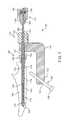
- FIG. 4is a plan view of a combination deployment tool that may be used with the bone fixation device of FIG. 1 .
- FIG. 5is a cross-section view of the tool and device shown in FIG. 4 .
- FIG. 6is a perspective view of the tool and device shown in FIG. 4 .
- FIG. 7is a cross-section view of the implanted device of FIG. 1 .
- FIG. 8is a perspective view of an alternative embodiment of the implanted device of FIG. 1 .
- FIG. 9is a perspective view of another alternative embodiment of the implanted device of FIG. 1 .
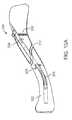
- FIG. 10Ais a perspective view of another embodiment of a bone fixation device shown deployed in a fractured clavicle.
- FIG. 10Bis perspective view of the device shown in FIG. 10A shown in a deployed state.
- FIG. 10Cis a side elevation view of the device shown in FIG. 10A shown in a retracted or undeployed state.
- FIG. 10Dis a side elevation view of the device shown in FIG. 10A shown in a deployed state.
- FIG. 10Eis a cross-sectional view of the device shown in FIG. 10A shown in a retracted or undeployed state.
- FIG. 10Fis a cross-sectional view of the device shown in FIG. 10A shown in a deployed state.
- FIG. 10Gis a perspective view of a gripper of the device shown in FIG. 10A shown in a retracted or undeployed state.
- FIG. 10His a side elevation view of a gripper and actuator of the device shown in FIG. 10A shown in a retracted or undeployed state.
- FIG. 10Iis a perspective view of a gripper and actuator of the device shown in FIG. 10A shown in a deployed state.
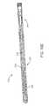
- FIG. 11Ais perspective view of another embodiment of a bone fixation device shown in a retracted or undeployed state.
- FIG. 11Bis perspective view of the device shown in FIG. 11A shown in a deployed state.
- FIG. 11Cis a cross-sectional view of the device shown in FIG. 11A shown in a retracted or undeployed state.
- FIG. 11Dis a cross-sectional view of the device shown in FIG. 11A shown in a deployed state.
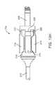
- FIGS. 12A-12Fshow various views of an exemplary embodiment of a bone fixation device hub.
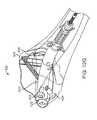
- FIGS. 12G-12Ishow various views of an exemplary embodiment of a bone fixation device implanted in a bone.
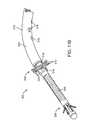
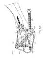
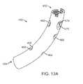
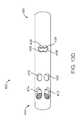
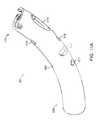
- FIGS. 13A-13Eshow various views of another exemplary embodiment of a bone fixation device hub.
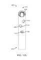
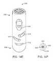
- FIGS. 14A-14Fshow various views of another exemplary embodiment of a bone fixation device hub.
- FIGS. 15A-15Dshow various views of another exemplary embodiment of a bone fixation device hub.
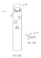
- FIGS. 16A-16Eshow various views of another exemplary embodiment of a bone fixation device hub.
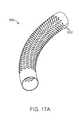
- FIGS. 17A-17Bshow various views of another exemplary embodiment of a bone fixation device hub.
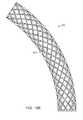
- FIGS. 18A-18Bshow various views of another exemplary embodiment of a bone fixation device hub.
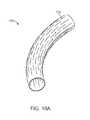
- FIGS. 19A-19Bshow various views of another exemplary embodiment of a bone fixation device hub.
- FIGS. 20A-20Bshow various views of another exemplary embodiment of a bone fixation device hub.
- boneis often described as a specialized connective tissue that serves three major functions anatomically.
- boneprovides a mechanical function by providing structure and muscular attachment for movement.
- boneprovides a metabolic function by providing a reserve for calcium and phosphate.
- boneprovides a protective function by enclosing bone marrow and vital organs.
- Bonescan be categorized as long bones (e.g. radius, femur, tibia and humerus) and flat bones (e.g. skull, scapula and mandible). Each bone type has a different embryological template. Further each bone type contains cortical and trabecular bone in varying proportions.
- the devices of this inventioncan be adapted for use in any of the bones of the body as will be appreciated by those skilled in the art.
- Cortical boneforms the shaft, or diaphysis, of long bones and the outer shell of flat bones.
- the cortical boneprovides the main mechanical and protective function.
- the trabecular bone(cancellous) is found at the end of the long bones, or the epiphysis, and inside the cortex of flat bones.
- the trabecular boneconsists of a network of interconnecting trabecular plates and rods and is the major site of bone remodeling and resorption for mineral homeostasis. During development, the zone of growth between the epiphysis and diaphysis is the metaphysis.
- woven bonewhich lacks the organized structure of cortical or cancellous bone, is the first bone laid down during fracture repair.
- the bone segmentsare positioned in proximity to each other in a manner that enables woven bone to be laid down on the surface of the fracture.
- This description of anatomy and physiologyis provided in order to facilitate an understanding of the invention. Persons of skill in the art will also appreciate that the scope and nature of the invention is not limited by the anatomy discussion provided. Further, it will be appreciated there can be variations in anatomical characteristics of an individual patient, as a result of a variety of factors, which are not described herein. Further, it will be appreciated there can be variations in anatomical characteristics between bones which are not described herein.
- FIGS. 1 and 2are perspective views of an embodiment of a bone fixation device 100 having a proximal end 102 (nearest the surgeon) and a distal end 104 (further from surgeon) and positioned within the bone space of a patient according to the invention.
- device 100is shown implanted in the upper (or proximal) end of an ulna 106 .
- the proximal end and distal endrefers to the position of an end of the device relative to the remainder of the device or the opposing end as it appears in the drawing.
- the proximal endcan be used to refer to the end manipulated by the user or physician.
- the distal endcan be used to refer to the end of the device that is inserted and advanced within the bone and is furthest away from the physician.
- proximal and distalcould change in another context, e.g. the anatomical context in which proximal and distal use the patient as reference, or where the entry point is distal from the surgeon.
- the deviceWhen implanted within a patient, the device can be held in place with suitable fasteners such as wire, screws, nails, bolts, nuts and/or washers.
- the device 100is used for fixation of fractures of the proximal or distal end of long bones such as intracapsular, intertrochanteric, intercervical, supracondular, or condular fractures of the femur; for fusion of a joint; or for surgical procedures that involve cutting a bone.
- the devices 100may be implanted or attached through the skin so that a pulling force (traction may be applied to the skeletal system).
- the design of the metaphyseal fixation device 100 depictedis adapted to provide a bone engaging mechanism or gripper 108 adapted to engage target bone of a patient from the inside of the bone.
- the deviceis designed to facilitate bone healing when placed in the intramedullary space within a post fractured bone.
- This device 100has a gripper 108 positioned distally and shown deployed radially outward against the wall of the intramedullary cavity. On entry into the cavity, gripper 108 is flat and retracted ( FIG. 3 ). Upon deployment, gripper 108 pivots radially outward and grips the diaphyseal bone from the inside of the bone.
- a flexible-to-rigid body portion 114may also be provided, and in this embodiment is positioned between gripper 108 and hub 112 . It may be provided with wavy spiral cuts 116 for that purpose, as will be described in more detail below.
- FIG. 3shows a longitudinal cross-section of device 100 in a non-deployed configuration.
- gripper 108includes two pairs of opposing bendable gripping members 118 . Two of the bendable gripping members 118 are shown in FIG. 3 , while the other two (not shown in FIG. 3 ) are located at the same axial location but offset by 90 degrees. Each bendable gripping member 118 has a thinned portion 120 that permits bending as the opposite distal end 122 of member 118 is urged radially outward, such that member 118 pivots about thinned portion 120 . When extended, distal ends 122 of bendable members 118 contact the inside of the bone to anchor the distal portion of device 100 to the bone.
- the grippermay comprise 1, 2, 3, 4, 5, 6 or more bendable members similar to members 118 shown.
- bendable members 118 of gripper 108are urged radially outward by a ramped surface on actuator head 124 .
- Actuator head 124is formed on the distal end of actuator 126 .
- the proximal end of actuator 126is threaded to engage a threaded bore of drive member 128 .
- the proximal end of drive member 128is provided with a keyed socket 130 for receiving the tip of a rotary driver tool 132 (shown in FIG. 5 ) through the proximal bore of device 100 .
- rotary driver tool 132turns drive member 128
- actuator 126is drawn in a proximal direction to outwardly actuate gripper members 118 .
- a hemispherical tip cover 134may be provided at the distal end of the device as shown to act as a blunt obturator. This arrangement facilitates penetration of bone (e.g. an intramedullary space) by device 100 while keeping the tip of device 100 from digging into bone during insertion.
- bonee.g. an intramedullary space
- device 100may include one or more flexible-to-rigid body portions 114 .
- This featureis flexible upon entry into bone and rigid upon application of compressive axial force provided by tensioning actuator 126 .
- Various embodiments of a flexible-to-rigid portionmay be used, including dual helical springs whose inner and outer tubular components coil in opposite directions, a chain of ball bearings with flats or roughened surfaces, a chain of cylinders with flats, features, cones, spherical or pointed interdigitating surfaces, wavy-helical cut tubes, two helical cut tubes in opposite directions, linear wires with interdigitating coils, and bellows-like structures.
- the design of the flexible-to-rigid tubular body portion 114allows a single-piece design to maximize the transformation of the same body from a very flexible member that minimizes strength in bending to a rigid body that maximizes strength in bending and torsion.
- the flexible membertransforms to a rigid member when compressive forces are applied in the axial direction at each end, such as by an actuator similar to 126 .
- the body portion 114is made, for example, by a near-helical cut 116 on a tubular member at an angle of incidence to the axis somewhere between 0 and 180 degrees from the longitudinal axis of the tubular body portion 114 .
- the near-helical cut or wavy-helical cutmay be formed by the superposition of a helical curve added to a cyclic curve that produces waves of frequencies equal or greater than zero per turn around the circumference and with cyclic amplitude greater than zero.
- the waves of one segmentnest with those on either side of it, thus increasing the torque, bending strength and stiffness of the tubular body when subjective to compressive forces.
- the tapered surfaces formed by the incident angleallow each turn to overlap or interdigitate with the segment on either side of it, thus increasing the bending strength when the body is in compression.
- the cutscan be altered in depth and distance between the cuts on the longitudinal axis along the length of body portion 114 to variably alter the flexible-to-rigid characteristics of the tubular body along its length.
- the cuts 116 in body portion 114allow an otherwise rigid member to increase its flexibility to a large degree during deployment.
- the tubular membercan have constant or varying internal and external diameters. This design reduces the number of parts of the flexible-to-rigid body portion of the device and allows insertion and extraction of the device through a curved entry port in the bone while maximizing its rigidity once inserted.
- Application and removal of compressive forces provided by a parallel membersuch as wire(s), tension ribbons, a sheath, wound flexible cable, or actuator 126 as shown will transform the body from flexible to rigid and vice versa.
- Body portion 114may be provided with a solid longitudinal portion 136 (as best seen in FIGS. 3 and 9 ) such that cuts 116 are a series of individual cuts each traversing less than 360 degrees in circumference, rather than a single, continuous helical cut.
- This solid portion 136can aid in removal of device 100 by keeping body portion 114 from extending axially like a spring.
- FIG. 4illustrates a combination tool 138 useful for inserting device 100 , actuating gripper 108 , compressing flexible-to-rigid body portion 114 , approximating the fracture in bone 106 , aligning anchor screw(s) 110 , and removing device 100 , if desired.
- tool 138includes an L-shaped body 140 that mounts the other components of the tool and also serves as a handle.
- the main components of tool 138are a device attachment portion 142 , a rotary driver 132 , an approximating driver 144 , and a screw alignment portion 146 .
- FIG. 5shows a cross-section of the tool 138 and device 100 illustrated in FIG. 4 .
- device attachment portion 142includes a knob 148 rigidly coupled to a tube 150 which is rotatably mounted within sleeve 152 .
- Sleeve 152in turn is fixedly mounted to tool body 140 .
- the distal end of tube 150is provided with external threads for engaging the internal threads on the proximal end of device 100 .
- both the distal end of sleeve 152 and the proximal end of device 100may be provided with semicircular steps that inter-engage to prevent device 100 from rotating with respect to sleeve 152 .
- device 100can be prevented from rotating when it is secured to tool 138 by tube 150 of device attachment portion 142 .
- the mating semicircular stepsalso serve to position device 100 in a particular axial and angular orientation with respect to tool 138 for aligning screws with screw holes, as will be later described.
- Rotary driver 132may be used to actuate gripper 108 and compress flexible-to-rigid body portion 114 after device 100 is inserted into bone 106 .
- Driver 132may also be used to allow body portion 114 to decompress and gripper 108 to retract if removal of device 100 from bone 106 is desired.
- driver 132includes knob 154 , torsion spring 156 , hub 158 , bushing 160 and shaft 162 .
- the distal end of shaft 162is provided with a mating tip 164 , such as one having a hex-key shape, for engaging with keyed socket 130 of device 100 (best seen in FIG. 3 ), such that turning driver shaft 162 turns drive member 128 and axially actuates actuator 126 , as described above.
- the proximal end of shaft 162may be fitted with a bushing 160 , such as with a press-fit.
- Hub 158may be secured over bushing 160 , such as with a pin through bushing 160 and shaft 162 .
- knob 154is rotatably mounted over hub 158 and bushing 160 such that knob 154 can rotate independently from shaft 162 .
- a torsion spring 156may be used to couple knob 154 to hub 158 as shown to create a torque limiting and/or torque measuring driver. With this indirect coupling arrangement, as knob 154 is rotated about shaft 162 , spring 156 urges hub 158 and shaft 162 to rotate in the same direction.
- Rotational resistance applied by device 100 to shaft tip 164will increase in this embodiment as gripper 108 engages bone 106 , and flexible-to-rigid body portion 114 compresses. As more torque is applied to knob 154 , it will advance rotationally with respect to hub 158 as torsion spring 156 undergoes more stress. Markings may be provided on knob 154 and hub 158 to indicate the torque being applied. In this manner, a surgeon can use driver 132 to apply torque to device 100 in a predetermined range. This can help ensure that gripper 108 is adequately set in bone 106 , body portion 114 is sufficiently compressed, and excessive torque is not being applied that might damage device 100 , bone 106 or cause slippage therebetween.
- a slip clutch or other mechanismmay be provided to allow the applied torque to be limited or indicated.
- driver 132may be configured to “click” into or out of a detent position when a desired torque is reached, thus allowing the surgeon to apply a desired torque without needing to observe any indicia on the driver.
- the driver knobmay be selectably or permanently coupled to shaft 162 directly.
- the approximating driver portion 144 of tool 138may be used to compress one or more fractures in bone 106 .
- Approximating driver 144includes knob 166 located on sleeve 152 .
- Knob 166may be knurled on an outer circumference, and have threads on at least a portion of its axial bore. The internal threads of knob 166 engage with mating external threads on sleeve 152 such that when knob 166 is rotated it advances axially with respect to sleeve 152 .
- sleeve 152is prevented from moving away from the bone.
- knob 166As knob 166 is advanced axially toward bone 106 , it serves to approximate bone fractures located between gripper 108 and knob 166 .
- Suitable thread pitch and knob circumferencemay be selected to allow a surgeon to supply a desired approximating force to bone 106 by using a reasonable rotation force on knob 166 .
- a torque indicating and/or torque limiting mechanism as described abovemay be incorporated into approximating driver 144 .
- tool 138may also include a screw alignment portion 146 .
- alignment portion 146includes a removable alignment tube 168 and two bores 170 and 172 through tool body 140 .
- a single bore or more than two boresmay be used, with or without the use of separate alignment tube(s).
- alignment tube 168is first received in bore 170 as shown. In this position, tube 168 is in axial alignment with angled hole 174 at the distal end 102 of device 100 . As described above, the mating semicircular steps of device 100 and sleeve 152 position angled hole 174 in its desired orientation. With this arrangement, a drill bit, screw driver, screw and/or other fastening device or tool may be inserted through the bore of tube 168 such that the device(s) are properly aligned with hole 174 . The outward end of alignment tube 168 may also serve as a depth guide to stop a drill bit, screw and/or other fastener from penetrating bone 106 beyond a predetermined depth.
- Alignment tube 168may be withdrawn from bore 170 as shown, and inserted in bore 172 . In this position, tube 168 aligns with hole 176 of device 100 . As described above, a drill bit, screw driver, screw and/or other fastening device may be inserted through the bore of tube 168 such that the device(s) are properly aligned with hole 176 .
- FIG. 6shows alignment tube 168 of tool 138 aligning screw 110 with angled hole 174 at the distal end of device 100 , as described above.
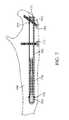
- FIG. 7shows a first screw 110 received through angled hole 174 and a second screw 110 received through hole 176 in device 100 and into bone 106 .
- Screws 110may be installed manually or with the aid of tool 138 as described above.
- the heads of screws 110may be configured to be self-countersinking such that they remain substantially beneath the outer surface of the bone when installed, as shown, so as to not interfere with adjacent tissue.
- the proximal end 102 of device 100is secured to bone 106 with two screws 110 , and the distal end 104 is secured by gripper 108 . In this manner, any bone fractures located between the proximal screw 110 and distal gripper 108 may be approximated and rigidly held together by device 100 .
- more than one grippermay be used, or only screws or other fasteners without grippers may be used to secure device 100 within bone 106 .
- the device shown in FIG. 1could be configured with a second gripper located between screw 110 and the middle of the device if the fracture is located more at the mid-shaft of the bone.
- more than two screws or other fastenersmay be used, or only grippers without fasteners may be used.
- holes such as 174 and 176 as shown and described abovecan be preformed in the implantable device. In other embodiments, some or all of the holes can be drilled or otherwise formed in situ after the device is implanted in the bone.
- combination tool 138may be removed by turning knob 148 to disengage threads of tube 150 from threads within the proximal end 102 of device 100 .
- An end plug 178may be threaded into the proximal end 102 of device 100 to preventing growth of tissue into implanted device 100 .
- Device 100may be left in bone 106 permanently, or it may be removed by performing the above described steps in reverse. In particular, plug 178 is removed, tool 138 is attached, screws 110 are removed, gripper 108 is retracted, and device 100 is pulled out using tool 138 .
- FIGS. 8 and 9show alternative embodiments similar to device 100 described above.
- Device 100 ′ shown in FIG. 8is essentially identical to device 100 described above but is shorter in length and utilizes a single anchor screw 110 at its proximal end 102 .
- Device 100 ′′ shown in FIG. 9is similar to device 100 ′, but is shorter still.
- the devicesmay be configured to have a nominal diameter of 3 mm, 4 mm, 5 mm or 6 mm. It is envisioned that all three device designs 100 , 100 ′ and 100 ′′ may each be provided in all three diameters such that the chosen device is best suited for the particular fracture(s) and anatomy in which it is implanted.
- the devicemay be made from a variety of materials such as metal, composite, plastic or amorphous materials, which include, but are not limited to, steel, stainless steel, cobalt chromium plated steel, titanium, nickel titanium alloy (nitinol), superelastic alloy, and polymethylmethacrylate (PMMA).
- the devicemay also include other polymeric materials that are biocompatible and provide mechanical strength, that include polymeric material with ability to carry and delivery therapeutic agents, that include bioabsorbable properties, as well as composite materials and composite materials of titanium and polyetheretherketone (PEEKTM), composite materials of polymers and minerals, composite materials of polymers and glass fibers, composite materials of metal, polymer, and minerals.
- PEEKTMpolyetheretherketone
- each of the aforementioned types of devicemay further be coated with proteins from synthetic or animal source, or include collagen coated structures, and radioactive or brachytherapy materials.
- the construction of the supporting framework or devicemay include radio-opaque markers or components that assist in their location during and after placement in the bone or other region of the musculo-skeletal systems.
- the reinforcement devicemay, in one embodiment, be osteo incorporating, such that the reinforcement device may be integrated into the bone.
- a low weight to volume devicedeployed in conjunction with other suitable materials to form a composite structure in-situ.
- suitable materialsmay include, but are not limited to, bone cement, high density polyethylene, Kapton®, polyetheretherketone(PEEKTM), and other engineering polymers.
- the devicemay be electrically, thermally, or mechanically passive or active at the deployed site within the body.
- the shape of the devicemay be dynamically modified using thermal, electrical or mechanical manipulation.
- the nitinol devicemay be expanded or contracted once deployed, to move the bone or other region of the musculo-skeletal system or area of the anatomy by using one or more of thermal, electrical or mechanical approaches.
- the inventive implantable device, tools and methodsmay be used in many locations within the body.
- the proximal end of a device in the anatomical contextis the end closest to the body midline and the distal end in the anatomical context is the end further from the body midline, for example, on the humerus, at the head of the humerus (located proximal, or nearest the midline of the body) or at the lateral or medial epicondyle (located distal, or furthest away from the midline); on the radius, at the head of the radius (proximal) or the radial styloid process (distal); on the ulna, at the head of the ulna (proximal) or the ulnar styloid process (distal); for the femur, at the greater trochanter (proximal) or the lateral epicondyle or medial epicondyle (distal); for the tibia, at the medial
- access locationsother than the ones described herein may also be suitable depending upon the location and nature of the fracture and the repair to be achieved.
- the devices taught hereinare not limited to use on the long bones listed above, but can also be used in other areas of the body as well, without departing from the scope of the invention. It is within the scope of the invention to adapt the device for use in flat bones as well as long bones.
- FIGS. 10A-10Ishow another embodiment of a bone fixation device constructed according to aspects of the invention.
- FIG. 10Ais a perspective view showing the exemplary device 200 deployed in a fractured clavicle 202 .
- Device 200is similar to device 100 described above and shown in FIGS. 1-7 , but has a gripper 204 located near its proximal end, another gripper 206 located at a more distal location, and a flexible-to-rigid body portion 208 located near the distal end of the device.
- a bone screw 210 and gripper 204are configured to secure device 200 inside bone 202 on the proximal side of fracture 212
- gripper 206 and flexible-to-rigid body portion 208are configured to secure device 200 on the distal side of fracture 212 .
- construction and operation of device 200is much like that of device 100 described above.
- each of the two grippers 204 and 206has four outwardly expanding arms 214 . These arms are spaced at 90 degree intervals around the circumference of the device body.
- the arms 214 of gripper 204may be offset by 45 degrees from arms 214 of gripper 206 as shown in the figures to distribute the forces applied by grippers 204 and 206 on the bone 202 .
- a single actuator 216may be used to deploy both grippers 204 and 206 .
- Actuator 216may also be used to axially compress flexible-to-rigid body portion 208 to make it substantially rigid.
- actuator 216may be flexible to allow flexible-to-rigid body portion 208 to assume a curved shape, as best seen in FIGS. 10A and 10B .
- the actuatormay be rigid and faulted with the desired straight and/or curved shape to match the flexible-to-rigid body portion.
- FIGS. 10G-10Ifurther details of an exemplary gripper 204 are shown.
- FIGS. 10G and 10Hshow gripper 204 with bendable arms 214 in a retracted state.
- cam 218 of actuator 216is driven axially into the distal ramped ends of arms 214
- arms 214bend at thinned portions 220 to move radially outward toward the deployed position shown in FIG. 10I .
- Notches 222may be provided in the distal ends of arms 214 as shown to allow arms 214 to better grip interior bone surfaces. Without departing from the scope of the invention, one, two, three, or more bendable arms may be used.
- Device 300includes a curved hub 302 , proximal gripper 304 , flexible-to-rigid body portion 306 , and distal gripper 308 .
- Distal gripper 308is similar in construction and operation to grippers 204 and 206 described above.
- Proximal gripper 304is provided with three pairs of scissor arms 310 . Each pair of arms 310 is pivotably interconnected at a mid-portion by a pin. Each arm is pivotably connected with a pin to either proximal end piece 312 or distal end piece 314 .
- arms 310pivot radially outward from an axially aligned retracted position, as shown in FIGS. 11A and 11C , to a deployed position, as shown in FIGS. 11B and 11D .
- the distal ends of the six arms 310engage an inner surface of a bone as previously described.
- device 300In operation, device 300 , with grippers 304 and 308 in a retracted state, may be inserted into the intramedullary space within a bone, such as the radius.
- Device 300may be inserted through a curved opening formed in the bone, such as an opening formed through a bony protuberance on a distal or proximal end or through the midshaft of the bone.
- Curved hub 302may be configured with the same geometry of the curved opening in the bone, and when the flexible-to-rigid body portion 306 is in its flexible state, it can assume this same geometry.
- 11C and 11Dmay be actuated from the proximal end of device 300 by turning drive member 317 in a manner similar to that previously described.
- Longitudinal movement of actuator 315 toward the proximal end of device 300causes flexible-to-rigid body portion 306 to foreshorten and assume its rigid state, and causes grippers 304 and 308 to outwardly deploy against the bone.
- Bone screwsmay be inserted through holes 316 shown in curved hub 302 to secure the proximal end of device 300 to the bone. Further details of the construction and operation of a device similar to device 300 may be found in co-pending U.S. application Ser. No. 11/944,366 filed Nov. 21, 2007 and entitled Fracture Fixation Device, Tools and Methods.
- Device 300is an example of an embodiment utilizing mixed gripper types. In other words, this device uses one scissors-arm tripod gripper 304 and one bendable-arm gripper 308 .
- Other embodiments of the inventionuse various combinations of gripper(s) and/or flexible-to-rigid body portion(s). Further exemplary gripper embodiments are described in detail in co-pending U.S. application Ser. No. 61/100,652 filed Sep. 26, 2008 and entitled Fracture Fixation Device, Tools and Methods. It is envisioned that virtually any combination of zero, one, two, or more grippers may be used in combination with zero, one, two or more flexible-to-rigid body portions to form a device adapted to a particular bone anatomy, fracture, disease state or fixation purpose.
- the grippers and/or flexible-to-rigid body portionsmay each be of identical or different construction, and may be placed together or at other locations along the device. Further, a straight, curved, flexible, rigid, or no hub at all may be used with the above combinations. Additionally, screws, K-wires, sutures or no additional fixation may be used with these various devices.
- the devicesmay be specially designed and constructed for a particular purpose or range of purposes. According to aspects of the invention, the components may also be designed to be interchangeable and/or produced in various sizes so that surgical kits may be provided. Such kits would allow surgical teams to select from a variety of components to build devices themselves, each suited to a particular patient's unique situation.
- FIGS. 12A through 20Bfurther examples of the hubs discussed above are shown and will now be described.
- FIGS. 12A-12Fshow details of a curved hub 400 similar to hub 302 illustrated in FIGS. 11A-11D .
- hub 400has an internally threaded portion at its proximal end 402 for engaging with an insertion and removal tool as described above. (The proximal end is referenced as the end closest to the surgeon.)
- the proximal end 402may also have a keyed feature for mating with the tool for maintaining a desired orientation of hub 400 relative to the tool.
- Hub 400may also be provided with a counterbore at its distal end 404 for coupling to a gripper or flexible-to-rigid body portion, such as by press fit and/or welding.
- Exemplary hub 400includes three holes 406 , 408 and 410 through the wall thickness on its concave side, as best seen in FIG. 12C .
- hub 400includes four holes 412 , 414 , 416 , and 418 through the wall thickness on its convex side, as best seen in FIG. 12D .
- At least a portion of all seven holesmay be seen in FIG. 12F .
- Holes 406 and 412 on opposite sides of hub 400are aligned to allow a bone screw to be inserted through the two holes across the hub to secure hub 400 to the bone and/or to secure bone fragment(s) with the screw.
- holes 408 and 414are aligned to receive a second bone screw
- holes 410 and 416are aligned to receive a third bone screw.
- a fourth screwmay be inserted through the open proximal end 402 of hub 400 and out through hole 418 .
- Each screwmay be passed first through cortical bone, then cancellous bone, then through the two holes of hub 400 , through more cancellous bone and possibly into more cortical bone on the opposite side of the bone from where the screw entered.
- the holes of hub 400have a diameter of 2.4 mm. In other embodiments, the holes have a diameter of 2.7 mm. In still other embodiments, the holes may have larger or smaller diameters.
- the holesmay be threaded during the fabrication of hub 400 , or threads may be formed in vivo.
- Various fixtures, jigs, tools and methodsmay be used to align the screws with the holes, such as a tool similar to tool 138 shown in FIGS. 4-6 and described above. Further examples of positioning aids are provided in copending U.S. application Ser. No. 11/944,366 filed Nov. 21, 2007 and entitled Fracture Fixation Device, Tools and Methods.
- the heads of the screwsmay be countersunk into the bone as described in copending U.S. application Ser. No. 61/117,901 filed Nov. 25, 2008 and entitled Bone Fracture Fixation Screws, Systems and Methods of Use.
- FIGS. 12G-12Iillustrate an example how bone screws 420 , 422 , 424 may be inserted through hub 400 ′ (which is similar to hub 400 ) as described above to secure the comminuted fracture depicted at the distal end of a radius bone 425 .
- hub 400 ′which is similar to hub 400
- One, two, three, four, or more screwsmay be used depending on the anatomy and fracture condition of each particular case. It should be noted that in this particular embodiment, either screw 422 or 424 may be placed through hub 400 ′, but not both at the same time, as their paths intersect inside hub 400 ′. It can be seen that screws 422 and 424 extend across fracture 426 into bone fragment 428 . Accordingly, either screw 422 or 424 may be used to approximate fracture 426 when the screw is tightened.
- FIGS. 13A-13Eshow another exemplary embodiment of a bone fixation device hub 450 .
- Hub 450is of similar construction to hub 400 described above and includes proximal end 452 and distal end 454 .
- hub 450includes four holes 456 , 458 , 460 , and 462 through the wall thickness on its concave side.
- Holes 456 and 458are located the same longitudinal distance from distal end 454 , but are symmetrically located on opposite sides of a central longitudinal plane. As can be seen, holes 456 and 458 actually overlap to form a single, figure-eight shaped hole.
- Holes 460 and 462are also located the same longitudinal distance from proximal end 452 , and are symmetrically located on opposite sides of a central longitudinal plane.
- hub 450also includes six holes 464 , 466 , 468 , 470 , 472 , and 474 through the wall thickness on its convex side.
- Holes 464 and 466are located the same longitudinal distance from distal end 454 , but are symmetrically located on opposite sides of a central longitudinal plane. Holes 464 and 466 also overlap to form a single, figure-eight shaped hole, similar to holes 456 and 458 described above.
- Holes 468 and 470are also located the same longitudinal distance from proximal end 452 , and are symmetrically located on opposite sides of a central longitudinal plane.
- holes 472 and 474are also located the same longitudinal distance from proximal end 452 , and are symmetrically located on opposite sides of a central longitudinal plane.
- Holes 456 and 464 on diagonally opposite sides of hub 450are aligned to allow a bone screw to be inserted through the two holes across the hub, passing through a centerline of hub 450 .
- holes 458 and 466 on diagonally opposite sides of hub 450are aligned to allow a bone screw to be inserted through the two holes across the hub, passing through a centerline of hub 450 . Since both of these two screw paths cross the centerline at the same location forming an X-pattern, only one screw may be placed through these two pairs of holes 456 / 464 and 458 / 466 in any particular procedure.
- holes 460 and 468 on diagonally opposite sides of hub 450are aligned to allow a bone screw to be inserted through the two holes across the hub, passing through a centerline of hub 450 .
- Holes 462 and 470 on diagonally opposite sides of hub 450are also aligned to allow a bone screw to be inserted through the two holes across the hub, passing through a centerline of hub 450 . Since both of these two screw paths cross the centerline at the same location forming an X-pattern, only one screw may be placed through these two pairs of holes 460 / 468 and 462 / 470 in any particular procedure.
- a third screwmay be inserted through the open proximal end 452 of hub 450 and out through either hole 472 or hole 474 . Since these two screw paths also overlap, only one screw may be placed though them at a time.
- exemplary hub 450is symmetrical about a central plane. Since hub 450 may receive up to three screws, each in one of two positions, there are a total of eight screw patterns that may be used with hub 450 , depending on the situation. Additionally, only one or two screws, or no screws, may be used in a particular procedure, if desired. The positions and orientations of the screw holes of hub 450 relative to previously described hub 400 may take better advantage of cortical bone locations in some procedures for better anchoring of bone screws.
- a screw passing through hole pairs 456 / 464 , 458 / 466 , 460 / 468 or 462 / 470 of hub 450will have a reduced angle relative to a longitudinal axis of a bone as compared with the screw trajectories of similar screws in hub 400 .
- a screw passing through either hole 472 or 474will have a different angle from the same screw in hub 400 , which in many cases allows the screw of hub 450 to hit harder bone.
- screw paths of hole pairs 460 / 468 and 462 / 470are closer to the proximal end of hub 450 than similar screw paths in hub 400 , allowing the screws to fixate in harder bone located near the end of a bone.
- All of the new screw trajectories provided by hub 450may be used with the in vivo hole forming hubs that will be later described below.
- the trajectories of hole pairs 456 / 464 , 458 / 466 , 460 / 468 or 462 / 470also form an angle with a central, longitudinal plane containing the curve of hub 450 (in other words, a plane of symmetry of the hole pairs.)
- the hole pairseach form an angle with the plane falling in a range of about 5 to 30 degrees.
- FIGS. 14A-14Eshow another exemplary embodiment of a bone fixation device hub 500 .
- Hub 500is of similar construction to hubs 400 and 450 described above and includes proximal end 502 and distal end 504 .
- hub 500includes slotted holes 506 , 508 , and 510 through the wall thickness on its concave side.
- hub 500also includes slotted holes 512 , 514 , and 516 , and angled hole 518 through the wall thickness on its convex side. Holes 506 and 512 on opposite sides of hub 500 are aligned to allow a first bone screw to be inserted through the two holes across the hub.
- holes 508 and 514are aligned to receive a second bone screw
- holes 510 and 516are aligned to receive a third bone screw
- Hole 518is aligned with the opening in the proximal end 502 of hub 500 to receive a fourth bone screw.
- the slotted configuration of hole pairs 506 / 512 , 508 / 514 , and 510 / 516allows a bone screw to be received through each of the pairs in a variety of orientations.
- This arrangementpermits a surgeon the flexibility to place bone screws where most appropriate in a particular procedure.
- a first bone screwmay be placed through holes 506 and 512 such that it resides in the left, middle, or right portion of hole 506 , as viewed in FIG. 14C .
- the same screwwill have another section that may reside in the left, middle, or right portion of hole 512 .
- the screwcan take one of nine basic orientations through holes 506 and 512 , as well as many other orientations between these nine.
- a slightly enlarged round holemay be provided on one side of the hub while a slotted hole on the opposite side forms the other hole of the pair.
- the width of slotted holes 506 , 508 , 510 , 512 , 514 , and 516is 2.0 mm. This provides a pilot hole in which a drill bit or screw tip may engage. Material from a portion of the sides of each hole may be removed when the drill bit forms a larger hole in one location of the slotted hole, and/or when a screw is inserted to form threads through the hole. No drilling or threading may be necessary, such as when the slot width is generally the same as the minor diameter of the screw, and the thickness of the hub walls is generally the same as the screw pitch.
- the slotted holesmay also stretch or deform when receiving the screw. As shown in FIG.
- relief slit(s) 520may be provided adjacent to a slotted hole 506 to allow the slot to more easily expand when receiving a screw 522 .
- Such slitsmay be formed by laser cutting, electron beam melting (EBM), electrical discharge machining (EDM), etching, stamping, milling, or other fabrication techniques.
- FIGS. 15A-15Dshow another exemplary embodiment of a bone fixation device hub 500 ′.
- Hub 500 ′is similar to hub 500 described above, but has slotted holes that are oriented longitudinally rather than transversely.
- Hub 500 ′includes proximal end 502 ′ and distal end 504 ′.
- hub 500 ′includes slotted holes 506 ′, 508 ′, and 510 ′ through the wall thickness on its concave side.
- hub 500 ′also includes slotted holes 512 ′, 514 ′, and 516 ′, and angled hole 518 ′ through the wall thickness on its convex side.
- Holes 506 ′ and 512 ′ on opposite sides of hub 500 ′are aligned to allow a first bone screw to be inserted through the two holes across the hub.
- holes 508 ′ and 514 ′are aligned to receive a second bone screw
- holes 510 ′ and 516 ′are aligned to receive a third bone screw.
- Hole 518 ′is aligned with the opening in the proximal end 502 ′ of hub 500 ′ to receive a fourth bone screw.
- Exemplary axis lines 524 , 526 , 528 , and 530are shown in FIG. 15A to show examples paths for the first, second, third, and fourth screws, respectively.
- FIGS. 16A-16Eshow another exemplary embodiment of a bone fixation device hub 550 .
- hub 550includes at its proximal end 552 a transversely elongated hole 554 .
- Hole 554allows a screw 556 to be located along the central axis, or off-axis in either direction as may be desired for engaging harder bone or securing additional bone fragment(s).
- This of arrangement of hole 554may be configured to hold screw 556 tightly at all angles. This may be accomplished, for example, by using a hole 554 slot width that is equal to or smaller than the minor diameter of screw 556 .
- the wall thickness of hub 550may fit into the screw threads, providing additional locking of screw 556 .
- the angle of elongated hole 554may be oriented differently as desired.
- screw 558has a tapered edge 560 below its head 562 . Tapered edge 560 serves to wedge screw 558 into slot 554 , securing the screw in place.
- a screw with an expanding head(not shown) may also be used. With this arrangement, a taper or other expanded section may be created once the screw is in place, thereby locking it in position.
- FIGS. 17A-17Cshow another exemplary embodiment of a bone fixation hub 600 .
- Hub 600is provided with an array of pilot holes 602 over most of its surface.
- Each hole 602may be 0.015 to 0.020 inches in diameter, for example, and serves as a starting point to allow a drill bit or screw tip to penetrate the wall thickness of hub 600 . This makes in vivo screw hole formation possible, while allowing the hub to remain a rigid structure.
- Holes 602may be closely spaced such that a screw or screws may be positioned in vivo virtually anywhere the surgeon desires during each particular procedure. Once the drill bit and/or screw is inserted, the hole 602 becomes enlarged to generally the minor diameter of the screw thread, such as to 2.7 mm in diameter, for example. Screw holes may be formed in this way on both sides of hub 600 in a continuous operation, allowing screw(s) to be positioned across the hub as previously described.
- pilot holes 602may be placed closer to one another so that multiple perforations are consumed by the screw diameter 604 when the screw hole is formed. This can make in vivo hole formation even easier.
- Other hole patternsthan those shown in FIGS. 17A-17C may be used.
- Holes 602may be fabricated in hub 600 by laser cutting, electron beam melting (EBM), electrical discharge machining (EDM), etching, stamping, drilling, or other fabrication techniques.
- EBMelectron beam melting
- EDMelectrical discharge machining
- FIGS. 18A and 18Bshow another exemplary embodiment of a bone fixation hub 650 .
- Hub 650has at least a portion that is fabricated from a mesh structure, forming a plurality of diamond or other shaped apertures 652 .
- Apertures 652may be configured with dimensions smaller than the major diameter of the threads of the bone screws to be used. Aperture dimensions may even be smaller than the minor thread diameter, such that the apertures are stretched and/or deformed as the screw enters the aperture, thereby providing an increased ability to hold the screws in place.
- the use of a mesh hub 650may reduce the amount or possibility of debris being formed and released inside the body during in vivo screw hole formation.
- Apertures 652may be fabricated in hub 650 by laser cutting, electron beam melting (EBM), electrical discharge machining (EDM), etching, stamping, drilling, or other fabrication techniques. Apertures 652 may also be fabricated by forming slits in plate or tube stock and expanding the material to form the apertures. Another fabrication technique that may be used is forming wires or bands around a mandrel and then welding, brazing, soldering, pressing, melting, gluing, or otherwise joining the wires or bands to each other at their intersections. Other types of porous structures, either with or without more random aperture locations, may be used as well. Multiple layers of mesh may also be combined.
- FIGS. 19A and 19Bshow another exemplary embodiment of a bone fixation hub 700 .
- Hub 700is provided with a plurality of thin slots 702 along its length. Slots 702 permit in vivo screw hole formation by acting as long pilot holes for drill bits or bone screws. A bone screw tip may be inserted into one of the slots 702 without pre-drilling. Upon insertion, the slot and surrounding slots will deform to make way for the screw, and will provide circumferential pressure to retain the screw.
- slots 702may be fabricated in hub 700 by laser cutting, electron beam melting (EBM), electrical discharge machining (EDM), etching, stamping, drilling, or other fabrication techniques. Thin slots 702 may generally require less material removal than other hub embodiments.
- EBMelectron beam melting
- EDMelectrical discharge machining
- FIGS. 20A and 20Bshow another exemplary embodiment of a bone fixation hub 750 .
- Hub 750comprises three separately formed hubs assembled together: an inner hub 752 , a mid-hub 754 , and an outer hub 756 .
- Mid-hub 754has a larger diameter than inner hub 752 so that mid-hub 754 may be placed over inner hub 752 , as illustrated in FIGS. 20A and 20B .
- outer hub 756has a larger diameter than mid-hub 754 so that outer hub 756 may be placed over mid-hub 754 , as also illustrated in the figures.
- all three hub components 752 , 754 , and 756have the same bend radius and the same arc length.
- the three hub components 752 , 754 , and 756may be retained at one or both ends by other components of the associated bone fixation device, and/or may be welded or otherwise fastened together.
- inner hub 752 and outer hub 756have spirally formed slots 758 and 760 , respectively. Slots 758 and 760 may be formed such that they line up when the individual hubs are assembled. Each hub 752 and 756 may also be provided with an upper spine ( 762 and 764 , respectively), and a lower spine (not seen in FIG. 20B ). The spines are solid regions running the length of the hubs that provide rigidity, and are positioned in areas that do not typically receive screws.
- Mid-hub 754has longitudinally extending slots 766 rather than spiral slots. When the three slot patterns are assembled in a coaxial unit, as shown in FIG. 20A , a hub is formed that may be quite rigid. Pilot holes are formed where slots 760 , 766 , and 758 line up radially to facilitate in vivo screw hole formation. When a screw is inserted in such a pilot hole, one or more of the slots may deform to receive the screw.
- One, two, three, four, or more hub layersmay be used in this manner to form a single layer or composite hub.
- Other slot patterns and widthsmay be used as appropriate.
- Some of the layersmay incorporate round or other aperture shapes instead of or in addition to the slots shown in this example.
- one or more screwsmay be placed into just a single side of the hub, or completely across the hub through both sides.
Landscapes
- Health & Medical Sciences (AREA)
- Orthopedic Medicine & Surgery (AREA)
- Surgery (AREA)
- Life Sciences & Earth Sciences (AREA)
- Heart & Thoracic Surgery (AREA)
- Nuclear Medicine, Radiotherapy & Molecular Imaging (AREA)
- Engineering & Computer Science (AREA)
- Biomedical Technology (AREA)
- Neurology (AREA)
- Medical Informatics (AREA)
- Molecular Biology (AREA)
- Animal Behavior & Ethology (AREA)
- General Health & Medical Sciences (AREA)
- Public Health (AREA)
- Veterinary Medicine (AREA)
- Surgical Instruments (AREA)
Abstract
Description
Claims (15)
Priority Applications (4)
| Application Number | Priority Date | Filing Date | Title |
|---|---|---|---|
| US12/642,648US8568413B2 (en) | 2008-12-18 | 2009-12-18 | Bone fixation device, tools and methods |
| US13/615,078US8961516B2 (en) | 2005-05-18 | 2012-09-13 | Straight intramedullary fracture fixation devices and methods |
| US13/614,523US9060820B2 (en) | 2005-05-18 | 2012-09-13 | Segmented intramedullary fracture fixation devices and methods |
| US14/020,685US20140031823A1 (en) | 2008-12-18 | 2013-09-06 | Bone fixation device, tools and methods |
Applications Claiming Priority (2)
| Application Number | Priority Date | Filing Date | Title |
|---|---|---|---|
| US13892008P | 2008-12-18 | 2008-12-18 | |
| US12/642,648US8568413B2 (en) | 2008-12-18 | 2009-12-18 | Bone fixation device, tools and methods |
Related Parent Applications (1)
| Application Number | Title | Priority Date | Filing Date |
|---|---|---|---|
| US12/482,406Continuation-In-PartUS8287541B2 (en) | 2005-05-18 | 2009-06-10 | Fracture fixation device, tools and methods |
Related Child Applications (4)
| Application Number | Title | Priority Date | Filing Date |
|---|---|---|---|
| PCT/US2009/046951Continuation-In-PartWO2009152272A1 (en) | 2005-05-18 | 2009-06-10 | Fracture fixation device, tools and methods |
| US13/615,078Continuation-In-PartUS8961516B2 (en) | 2005-05-18 | 2012-09-13 | Straight intramedullary fracture fixation devices and methods |
| US13/614,523Continuation-In-PartUS9060820B2 (en) | 2005-05-18 | 2012-09-13 | Segmented intramedullary fracture fixation devices and methods |
| US14/020,685ContinuationUS20140031823A1 (en) | 2008-12-18 | 2013-09-06 | Bone fixation device, tools and methods |
Publications (2)
| Publication Number | Publication Date |
|---|---|
| US20110087227A1 US20110087227A1 (en) | 2011-04-14 |
| US8568413B2true US8568413B2 (en) | 2013-10-29 |
Family
ID=43855424
Family Applications (2)
| Application Number | Title | Priority Date | Filing Date |
|---|---|---|---|
| US12/642,648Expired - Fee RelatedUS8568413B2 (en) | 2005-05-18 | 2009-12-18 | Bone fixation device, tools and methods |
| US14/020,685AbandonedUS20140031823A1 (en) | 2008-12-18 | 2013-09-06 | Bone fixation device, tools and methods |
Family Applications After (1)
| Application Number | Title | Priority Date | Filing Date |
|---|---|---|---|
| US14/020,685AbandonedUS20140031823A1 (en) | 2008-12-18 | 2013-09-06 | Bone fixation device, tools and methods |
Country Status (1)
| Country | Link |
|---|---|
| US (2) | US8568413B2 (en) |
Cited By (34)
| Publication number | Priority date | Publication date | Assignee | Title |
|---|---|---|---|---|
| US20130236853A1 (en)* | 2010-06-03 | 2013-09-12 | Tigran Technologies Ab (Publ) | 3d ductile and perforated retaining sheet |
| US20140058390A1 (en)* | 2010-01-15 | 2014-02-27 | Conventus Orthopaedics, Inc. | Rotary-rigid orthopaedic rod |
| US8906022B2 (en) | 2010-03-08 | 2014-12-09 | Conventus Orthopaedics, Inc. | Apparatus and methods for securing a bone implant |
| US8956394B1 (en) | 2014-08-05 | 2015-02-17 | Woven Orthopedic Technologies, Llc | Woven retention devices, systems and methods |
| US8961518B2 (en) | 2010-01-20 | 2015-02-24 | Conventus Orthopaedics, Inc. | Apparatus and methods for bone access and cavity preparation |
| USD740427S1 (en) | 2014-10-17 | 2015-10-06 | Woven Orthopedic Technologies, Llc | Orthopedic woven retention device |
| US9271743B2 (en) | 2012-08-09 | 2016-03-01 | Wilson Theophilo Asfora | System for joint fusion |
| US20160324551A1 (en)* | 2011-09-22 | 2016-11-10 | Mx Orthopedics, Corp. | Osteosynthetic shape memory material intramedullary bone stent and method for treating a bone fracture using the same |
| US9517093B2 (en) | 2008-01-14 | 2016-12-13 | Conventus Orthopaedics, Inc. | Apparatus and methods for fracture repair |
| US9545252B2 (en) | 2009-07-16 | 2017-01-17 | Howmedica Osteonics Corp. | Suture anchor implantation instrumentation system |
| US9585695B2 (en) | 2013-03-15 | 2017-03-07 | Woven Orthopedic Technologies, Llc | Surgical screw hole liner devices and related methods |
| US9770278B2 (en) | 2014-01-17 | 2017-09-26 | Arthrex, Inc. | Dual tip guide wire |
| US9907593B2 (en) | 2014-08-05 | 2018-03-06 | Woven Orthopedic Technologies, Llc | Woven retention devices, systems and methods |
| WO2017120327A3 (en)* | 2016-01-05 | 2018-03-29 | Conventus Orthopaedics, Inc. | Bone fracture repair apparatus and methods |
| US20180085151A1 (en)* | 2015-04-16 | 2018-03-29 | Texas Tech University System | Ankle (Tibio-Talar) Fusion Nail |
| US9943351B2 (en) | 2014-09-16 | 2018-04-17 | Woven Orthopedic Technologies, Llc | Woven retention devices, systems, packaging, and related methods |
| US10022132B2 (en) | 2013-12-12 | 2018-07-17 | Conventus Orthopaedics, Inc. | Tissue displacement tools and methods |
| US10136929B2 (en) | 2015-07-13 | 2018-11-27 | IntraFuse, LLC | Flexible bone implant |
| US10154863B2 (en) | 2015-07-13 | 2018-12-18 | IntraFuse, LLC | Flexible bone screw |
| US10231744B2 (en) | 2009-08-20 | 2019-03-19 | Howmedica Osteonics Corp. | Flexible ACL instrumentation, kit and method |
| US10485595B2 (en) | 2015-07-13 | 2019-11-26 | IntraFuse, LLC | Flexible bone screw |
| US10499960B2 (en) | 2015-07-13 | 2019-12-10 | IntraFuse, LLC | Method of bone fixation |
| US10555758B2 (en) | 2015-08-05 | 2020-02-11 | Woven Orthopedic Technologies, Llc | Tapping devices, systems and methods for use in bone tissue |
| US10918426B2 (en) | 2017-07-04 | 2021-02-16 | Conventus Orthopaedics, Inc. | Apparatus and methods for treatment of a bone |
| US11033394B2 (en) | 2016-10-25 | 2021-06-15 | Institute for Musculoskeletal Science and Education, Ltd. | Implant with multi-layer bone interfacing lattice |
| US11395681B2 (en) | 2016-12-09 | 2022-07-26 | Woven Orthopedic Technologies, Llc | Retention devices, lattices and related systems and methods |
| US11793652B2 (en) | 2017-11-21 | 2023-10-24 | Institute for Musculoskeletal Science and Education, Ltd. | Implant with improved bone contact |
| US11819253B2 (en) | 2020-05-29 | 2023-11-21 | Stryker European Operations Limited | Funnel hole for intramedullary nail |
| US11819419B2 (en) | 2015-04-29 | 2023-11-21 | Institute for Musculoskeletal Science and Education, Ltd. | Implant with curved bone contacting elements |
| US11826261B2 (en) | 2015-04-29 | 2023-11-28 | Institute for Musculoskeletal Science and Education, Ltd. | Coiled implants and systems and methods of use thereof |
| US11938039B2 (en) | 2017-03-13 | 2024-03-26 | Institute for Musculoskeletal Science and Education, Ltd. | Implant with structural members arranged around a ring |
| US11951018B2 (en) | 2017-11-21 | 2024-04-09 | Institute for Musculoskeletal Science and Education, Ltd. | Implant with improved flow characteristics |
| US12042399B2 (en) | 2016-10-25 | 2024-07-23 | Institute for Musculoskeletal Science and Education, Ltd. | Implant with protected fusion zones |
| US12097123B2 (en) | 2015-04-29 | 2024-09-24 | Institute for Musculoskeletal Science and Education, Ltd. | Implant with arched bone contacting elements |
Families Citing this family (47)
| Publication number | Priority date | Publication date | Assignee | Title |
|---|---|---|---|---|
| US9060820B2 (en) | 2005-05-18 | 2015-06-23 | Sonoma Orthopedic Products, Inc. | Segmented intramedullary fracture fixation devices and methods |
| US8961516B2 (en) | 2005-05-18 | 2015-02-24 | Sonoma Orthopedic Products, Inc. | Straight intramedullary fracture fixation devices and methods |
| US7749249B2 (en) | 2006-02-21 | 2010-07-06 | Kardium Inc. | Method and device for closing holes in tissue |
| US8449605B2 (en) | 2006-06-28 | 2013-05-28 | Kardium Inc. | Method for anchoring a mitral valve |
| US7837610B2 (en) | 2006-08-02 | 2010-11-23 | Kardium Inc. | System for improving diastolic dysfunction |
| WO2008064346A2 (en) | 2006-11-22 | 2008-05-29 | Sonoma Orthopedic Products, Inc. | Fracture fixation device, tools and methods |
| AU2008228710A1 (en)* | 2007-03-22 | 2008-09-25 | Novalign Orthopaedics, Inc. | Segmented intramedullary structure |
| US20090018542A1 (en)* | 2007-07-11 | 2009-01-15 | Sonoma Orthopedic Products,Inc. | Fracture fixation devices, systems and methods incorporating a membrane |
| US20090287304A1 (en) | 2008-05-13 | 2009-11-19 | Kardium Inc. | Medical Device for Constricting Tissue or a Bodily Orifice, for example a mitral valve |
| JP2011523889A (en) | 2008-06-10 | 2011-08-25 | ソノマ・オーソペディック・プロダクツ・インコーポレーテッド | Device, tool and method for fixing fractures |
| US9017329B2 (en)* | 2008-06-24 | 2015-04-28 | Extremity Medical, Llc | Intramedullary fixation assembly and method of use |
| US8313487B2 (en)* | 2008-06-24 | 2012-11-20 | Extremity Medical Llc | Fixation system, an intramedullary fixation assembly and method of use |
| JP2012504027A (en) | 2008-09-26 | 2012-02-16 | ソノマ・オーソペディック・プロダクツ・インコーポレーテッド | Bone fixation device, tool and method |
| US8888791B2 (en)* | 2008-10-07 | 2014-11-18 | Kardium Inc. | Surgical instrument and method for tensioning and securing a flexible suture |
| US9023058B2 (en)* | 2008-10-07 | 2015-05-05 | Kardium Inc. | Surgical instrument and method for tensioning and securing a flexible suture |
| WO2011041571A2 (en) | 2009-10-01 | 2011-04-07 | Kardium Inc. | Medical device, kit and method for constricting tissue or a bodily orifice, for example, a mitral valve |
| US8357162B2 (en)* | 2010-01-13 | 2013-01-22 | Paul Christopher Frake | Intramedullary mandibular condyle implants and method for application of the same |
| US9050066B2 (en) | 2010-06-07 | 2015-06-09 | Kardium Inc. | Closing openings in anatomical tissue |
| US8940002B2 (en) | 2010-09-30 | 2015-01-27 | Kardium Inc. | Tissue anchor system |
| US9072511B2 (en) | 2011-03-25 | 2015-07-07 | Kardium Inc. | Medical kit for constricting tissue or a bodily orifice, for example, a mitral valve |
| CA2847608C (en)* | 2011-09-16 | 2016-07-05 | Stryker Trauma Gmbh | Polyaxial locking hole arrangement |
| US10039556B2 (en) | 2011-11-10 | 2018-08-07 | David Michael Burt | Arthroscopic total shoulder arthroplasty |
| EP3326558B1 (en) | 2011-11-14 | 2025-04-30 | The University of British Columbia | Intramedullary fixation system for management of pelvic and acetabular fractures |
| EP2811927B1 (en) | 2012-02-07 | 2017-05-10 | MNR Device Corporation | Apparatus for treating a bone fracture |
| US11051864B2 (en)* | 2012-08-30 | 2021-07-06 | DePuy Synthes Products, Inc. | Intramedullary fixation assembly |
| US8721644B1 (en)* | 2013-03-08 | 2014-05-13 | Ta-Lun Tan | Intramedullary apparatus and methods of treating bone fracture using the same |
| US9138317B2 (en) | 2013-03-14 | 2015-09-22 | Osteoceramics, Inc | Conduits for enhancing tissue regeneration |
| US9039781B2 (en) | 2013-03-15 | 2015-05-26 | Osteoceramics, Inc. | Devices, systems, and methods for elongating bone |
| US20160051295A1 (en)* | 2013-04-11 | 2016-02-25 | K. N. Medical. Co., Ltd. | Osteosynthesis device |
| US9744008B2 (en) | 2013-05-06 | 2017-08-29 | Zimmer Dental, Inc. | Surgical tool with flexible shaft |
| WO2015134750A1 (en) | 2014-03-06 | 2015-09-11 | University Of British Columbia | Shape adaptable intramedullary fixation device |
| US10543026B2 (en)* | 2014-04-21 | 2020-01-28 | The General Hospital Corporation | Fracture fixation device having clip for stabilizing intramedullary nail |
| US9814499B2 (en) | 2014-09-30 | 2017-11-14 | Arthrex, Inc. | Intramedullary fracture fixation devices and methods |
| JP6389002B2 (en)* | 2014-10-14 | 2018-09-12 | ザ ユニヴァーシティ オブ ブリティッシュ コロンビア | System and method for intramedullary bone fixation |
| AU2016382956A1 (en)* | 2015-12-28 | 2018-08-09 | Glenhurst Labs, Llc | Surgical devices for small bone fracture surgery |
| EP3522803A4 (en) | 2016-10-05 | 2020-05-27 | The University of British Columbia | Intramedullary fixation device with shape locking interface |
| US10932828B2 (en) | 2018-01-25 | 2021-03-02 | Advanced Orthopaedic Solutions, Inc. | Bone nail |
| WO2020036865A1 (en)* | 2018-08-14 | 2020-02-20 | Arthrex, Inc. | Intramedullary implant systems and methods |
| CN112912022A (en) | 2018-10-17 | 2021-06-04 | 不列颠哥伦比亚大学 | Bone fixation device and system |
| IL268608B (en)* | 2019-08-08 | 2021-03-01 | Konstantinovsky Yevgeny | An intramedullary affixing apparatus |
| EP3932369B1 (en)* | 2020-06-03 | 2025-06-04 | Howmedica Osteonics Corp. | Intercalary endoprosthesis |
| CA3182316A1 (en)* | 2020-06-19 | 2021-12-23 | Edwards Lifesciences Innovation (Israel) Ltd. | Self-stopping tissue anchors |
| US12132227B2 (en) | 2021-01-19 | 2024-10-29 | Lg Energy Solution, Ltd. | Battery, and battery pack and vehicle comprising the same |
| IT202100028847A1 (en)* | 2021-11-12 | 2023-05-12 | Luciano Trinchese | Device for osteosynthesis. |
| CN114145807A (en)* | 2021-12-07 | 2022-03-08 | 自贡市第一人民医院 | Temporal bone styloid process truncator |
| WO2024182512A1 (en)* | 2023-02-28 | 2024-09-06 | Glw, Inc. | Intramedullary nail with automatic dynamization and continuous compression |
| CN118000874B (en)* | 2023-12-12 | 2024-07-16 | 中国人民解放军总医院第四医学中心 | A proximal femoral intraosseous release device |
Citations (84)
| Publication number | Priority date | Publication date | Assignee | Title |
|---|---|---|---|---|
| US958127A (en) | 1909-11-04 | 1910-05-17 | Knut T Hovrud | Pole-anchor. |
| US1169635A (en) | 1915-07-07 | 1916-01-25 | Lester A Grimes | Pipe-hanger. |
| US1790841A (en) | 1931-02-03 | Expansion bolt | ||
| US2221498A (en)* | 1937-10-04 | 1940-11-12 | Tinnerman Products Inc | Sheet metal fastening means |
| US2502267A (en) | 1946-03-13 | 1950-03-28 | Robert L Mcpherson | Self-clinching fastener |
| US2685877A (en) | 1952-03-20 | 1954-08-10 | Dobelle Martin | Femoral head prosthesis |
| US2896495A (en)* | 1957-03-28 | 1959-07-28 | Loyal D Crawford | Self-threading nut |
| US2908309A (en)* | 1956-10-30 | 1959-10-13 | Adelaide E Brill | Threadless plastic nut having stepped bore sections |
| US2998007A (en) | 1955-02-19 | 1961-08-29 | Herzog Kurt | Internal tubular splint for the fixation of bone fractures and method of applying it |
| US3118444A (en) | 1961-11-20 | 1964-01-21 | Jr Jose C Serrato | Forearm rod for fractures |
| US3441017A (en) | 1965-03-24 | 1969-04-29 | Hans Jurgen Kaessmann | Apparatus for the treatment of fractures of tubular bones |
| US3602218A (en)* | 1969-04-16 | 1971-08-31 | Zimmer Mfg Co | Sterile disposable finger pin |
| US3760802A (en) | 1971-02-26 | 1973-09-25 | Fischer Artur | Supporting device for fractured tubular bones |
| US3779239A (en) | 1971-03-13 | 1973-12-18 | Fischer Artur | Connector for fractured bones |
| US3791380A (en) | 1971-12-13 | 1974-02-12 | G Dawidowski | Method and apparatus of immobilizing a fractured femur |
| US3846846A (en) | 1972-09-28 | 1974-11-12 | Fischer Artur | Hip joint prosthesis |
| US3986504A (en) | 1974-10-25 | 1976-10-19 | Rafael Pares Avila | Internal fixation device for securing two fractured bone joints together |
| US4050464A (en) | 1975-04-28 | 1977-09-27 | Downs Surgical Limited | Surgical cable tensioning instrument |
| US4065816A (en) | 1975-05-22 | 1978-01-03 | Philip Nicholas Sawyer | Surgical method of using a sterile packaged prosthesis |
| US4091806A (en) | 1976-01-13 | 1978-05-30 | Jacob Aginsky | Intramedullary compression nail for the treatment of bone fractures |
| US4262665A (en) | 1979-06-27 | 1981-04-21 | Roalstad W L | Intramedullary compression device |
| US4275717A (en) | 1979-07-27 | 1981-06-30 | Zimmer Usa, Inc. | Intramedullary fixation device for fractured tubular bones |
| US4353358A (en) | 1980-08-28 | 1982-10-12 | Emerson Reynolds L | Sigmoidoscope |
| US4622959A (en) | 1985-03-05 | 1986-11-18 | Marcus Randall E | Multi-use femoral intramedullary nail |
| US4753657A (en) | 1984-01-16 | 1988-06-28 | University Of Exeter | Fixation of implants in bone |
| US4805595A (en) | 1987-04-28 | 1989-02-21 | Olympus Optical Co., Ltd. | Flexible tube assembly for endoscope |
| US5057103A (en) | 1990-05-01 | 1991-10-15 | Davis Emsley A | Compressive intramedullary nail |
| US5458653A (en) | 1991-07-15 | 1995-10-17 | Smith & Nephew Richards, Inc. | Prosthetic implants with bioabsorbable coatings |
| US5472444A (en) | 1994-05-13 | 1995-12-05 | Acumed, Inc. | Humeral nail for fixation of proximal humeral fractures |
| US5702215A (en) | 1995-06-05 | 1997-12-30 | Li Medical Technologies, Inc. | Retractable fixation device |
| US5772663A (en) | 1994-02-17 | 1998-06-30 | Whiteside; Leo A. | Surgical device for banding bone with cable |
| US5807241A (en) | 1995-09-22 | 1998-09-15 | Richard Wolf Gmbh | Bendable tube and method for its manufacture |
| US5836949A (en) | 1997-05-05 | 1998-11-17 | Campbell, Jr.; Robert M. | Bioabsorbable intermedullary implant system and methods of use |
| US5849004A (en) | 1996-07-17 | 1998-12-15 | Bramlet; Dale G. | Surgical anchor |
| US5879352A (en) | 1994-10-14 | 1999-03-09 | Synthes (U.S.A.) | Osteosynthetic longitudinal alignment and/or fixation device |
| US5928259A (en) | 1993-09-21 | 1999-07-27 | United States Surgical Corporation | Surgical instrument for expanding body tissue |
| US6019761A (en)* | 1998-12-23 | 2000-02-01 | Gustilo; Ramon B. | Intramedullary nail and method of use |
| US6053922A (en) | 1995-07-18 | 2000-04-25 | Krause; William R. | Flexible shaft |
| US6077264A (en) | 1996-04-05 | 2000-06-20 | Chemello; Antonio | Intramedullary nail for the osteosynthesis of bone fractures |
| US6443992B2 (en) | 1997-03-20 | 2002-09-03 | Philipp Lubinus | Milling tool for emptying the femoral medullary space and hip prosthesis to be inserted in the space created |
| US6447518B1 (en) | 1995-07-18 | 2002-09-10 | William R. Krause | Flexible shaft components |
| US20020161369A1 (en) | 2001-04-25 | 2002-10-31 | Bramlet Dale G. | Intramedullary nail |
| US20020188297A1 (en) | 1998-09-28 | 2002-12-12 | Dakin Edward B. | Internal cord fixation device |
| US20030045919A1 (en) | 2001-08-31 | 2003-03-06 | Swoyer John Matthew | Implantable medical electrical stimulation lead fixation method and apparatus |
| US6554833B2 (en) | 1998-10-26 | 2003-04-29 | Expanding Orthopedics, Inc. | Expandable orthopedic device |
| US6558388B1 (en) | 1999-08-30 | 2003-05-06 | Sulzer Orthopedics Ltd. | Intramedullary nail for the humerus |
| US6575973B1 (en) | 2000-10-26 | 2003-06-10 | Safedrip Ltd. | Self locking intramedullary nail |
| US6648890B2 (en) | 1996-11-12 | 2003-11-18 | Triage Medical, Inc. | Bone fixation system with radially extendable anchor |
| US20030236529A1 (en) | 2002-06-24 | 2003-12-25 | Endius Incorporated | Surgical instrument for moving vertebrae |
| US6688822B2 (en) | 2001-09-07 | 2004-02-10 | Ritter Gmbh | Plastic injection anchoring sleeve |
| US6695844B2 (en) | 1996-03-13 | 2004-02-24 | Orthopedic Designs, Inc. | Surgical fastener assembly |
| US20040133204A1 (en) | 2001-01-27 | 2004-07-08 | Davies John Bruce Clayfield | Expandable bone nails |
| US20040236327A1 (en) | 2003-05-23 | 2004-11-25 | Paul David C. | Spine stabilization system |
| US20050047892A1 (en)* | 2003-08-29 | 2005-03-03 | Bremner Ronald Dean | Laser cut apertures for thread forming fasteners |
| US6863692B2 (en) | 2002-11-14 | 2005-03-08 | Zimmer Technology, Inc. | Implant sleeve and method |
| US6866455B2 (en) | 2001-11-09 | 2005-03-15 | HÄFELE GmbH & CO. | Connecting member for connecting two structural components |
| US20050080425A1 (en) | 2002-03-18 | 2005-04-14 | Mohit Bhatnagar | Minimally invasive bone manipulation device and method of use |
| US20050165395A1 (en) | 2004-01-23 | 2005-07-28 | Orbay Jorge L. | System for stabilization of fractures of convex articular bone surfaces including subchondral support structure |
| US20050177158A1 (en) | 2004-02-09 | 2005-08-11 | Doubler Robert L. | Intramedullary screw and tang for orthopedic surgery |
| US20050216007A1 (en) | 2004-03-29 | 2005-09-29 | Christian Woll | Orthopedic intramedullary fixation system |
| EP1582163A1 (en) | 2004-03-31 | 2005-10-05 | Orthofix International B.V. | Intramedullary nail comprising an helical element of shape-memory material |
| US20060036248A1 (en) | 2004-07-01 | 2006-02-16 | Ferrante Joseph M | Fixation elements |
| US20060084997A1 (en)* | 2004-10-05 | 2006-04-20 | Michigan State University, A Michigan Corporation | Devices and methods for interlocking surgical screws and nails |
| US20060247638A1 (en)* | 2005-04-29 | 2006-11-02 | Sdgi Holdings, Inc. | Composite spinal fixation systems |
| US20060264952A1 (en)* | 2005-05-18 | 2006-11-23 | Nelson Charles L | Methods of Using Minimally Invasive Actuable Bone Fixation Devices |
| US20070123878A1 (en)* | 2005-10-21 | 2007-05-31 | Shaver Joseph A | Orthopedic rod with locking aperture |
| US20070142916A1 (en) | 2005-12-21 | 2007-06-21 | Olson Stanley W Jr | Bone graft composition, method and implant |
| EP1815813A2 (en) | 2004-03-31 | 2007-08-08 | ORTHOFIX S.r.l. | Intramedullary nail comprising elements of shape-memory material |
| US20070260257A1 (en) | 2005-07-11 | 2007-11-08 | Phan Christopher U | Surgical device having interchangeable components and methods of use |
| US20080132896A1 (en) | 2006-11-22 | 2008-06-05 | Sonoma Orthopedic Products, Inc. | Curved orthopedic tool |
| US20080140078A1 (en) | 2006-11-22 | 2008-06-12 | Sonoma Orthopedic Products, Inc. | Surgical tools for use in deploying bone repair devices |
| US20080161805A1 (en)* | 2006-11-22 | 2008-07-03 | Sonoma Orthopedic Products, Inc. | Fracture fixation device, tools and methods |
| US20080206015A1 (en)* | 2007-02-28 | 2008-08-28 | Baier & Michels Gmbh Und Co. Kg | Screw comprising a thread-forming thread, blank for the production of said screw, and screw connection |
| US20080255560A1 (en) | 2004-05-21 | 2008-10-16 | Myers Surgical Solutions, Llc | Fracture Fixation and Site Stabilization System |
| US20080269751A1 (en)* | 2007-01-11 | 2008-10-30 | Anthem Orthopaedics Llc | Percutaneous intramedullary bone repair device and method for using same |
| US20080287951A1 (en)* | 2007-03-22 | 2008-11-20 | Stoneburner James D | Segmented intramedullary structure |
| US20090018542A1 (en) | 2007-07-11 | 2009-01-15 | Sonoma Orthopedic Products,Inc. | Fracture fixation devices, systems and methods incorporating a membrane |
| US20090182336A1 (en) | 2008-01-14 | 2009-07-16 | Brenzel Michael P | Apparatus and methods for fracture repair |
| US20100023010A1 (en) | 2005-05-18 | 2010-01-28 | Nelson Charles L | Fracture fixation device, tools and methods |
| US20110178520A1 (en) | 2010-01-15 | 2011-07-21 | Kyle Taylor | Rotary-rigid orthopaedic rod |
| US20110190832A1 (en) | 2010-01-20 | 2011-08-04 | Kyle Taylor | Apparatus and methods for bone access and cavity preparation |
| US20110218626A1 (en) | 2010-03-08 | 2011-09-08 | Krinke Todd A | Apparatus and methods for securing a bone implant |
| US20110218585A1 (en) | 2010-03-08 | 2011-09-08 | Krinke Todd A | Apparatus and methods for bone repair |
| US20110282346A1 (en) | 2008-06-10 | 2011-11-17 | Sonoma Orthopedic Products, Inc. | Fracture Fixation Device, Tools and Methods |
Family Cites Families (1)
| Publication number | Priority date | Publication date | Assignee | Title |
|---|---|---|---|---|
| US4050646A (en)* | 1975-12-05 | 1977-09-27 | Burchette Jr Robert L | Yarn carrier |
- 2009
- 2009-12-18USUS12/642,648patent/US8568413B2/ennot_activeExpired - Fee Related
- 2013
- 2013-09-06USUS14/020,685patent/US20140031823A1/ennot_activeAbandoned
Patent Citations (95)
| Publication number | Priority date | Publication date | Assignee | Title |
|---|---|---|---|---|
| US1790841A (en) | 1931-02-03 | Expansion bolt | ||
| US958127A (en) | 1909-11-04 | 1910-05-17 | Knut T Hovrud | Pole-anchor. |
| US1169635A (en) | 1915-07-07 | 1916-01-25 | Lester A Grimes | Pipe-hanger. |
| US2221498A (en)* | 1937-10-04 | 1940-11-12 | Tinnerman Products Inc | Sheet metal fastening means |
| US2502267A (en) | 1946-03-13 | 1950-03-28 | Robert L Mcpherson | Self-clinching fastener |
| US2685877A (en) | 1952-03-20 | 1954-08-10 | Dobelle Martin | Femoral head prosthesis |
| US2998007A (en) | 1955-02-19 | 1961-08-29 | Herzog Kurt | Internal tubular splint for the fixation of bone fractures and method of applying it |
| US2908309A (en)* | 1956-10-30 | 1959-10-13 | Adelaide E Brill | Threadless plastic nut having stepped bore sections |
| US2896495A (en)* | 1957-03-28 | 1959-07-28 | Loyal D Crawford | Self-threading nut |
| US3118444A (en) | 1961-11-20 | 1964-01-21 | Jr Jose C Serrato | Forearm rod for fractures |
| US3441017A (en) | 1965-03-24 | 1969-04-29 | Hans Jurgen Kaessmann | Apparatus for the treatment of fractures of tubular bones |
| US3602218A (en)* | 1969-04-16 | 1971-08-31 | Zimmer Mfg Co | Sterile disposable finger pin |
| US3760802A (en) | 1971-02-26 | 1973-09-25 | Fischer Artur | Supporting device for fractured tubular bones |
| US3779239A (en) | 1971-03-13 | 1973-12-18 | Fischer Artur | Connector for fractured bones |
| US3791380A (en) | 1971-12-13 | 1974-02-12 | G Dawidowski | Method and apparatus of immobilizing a fractured femur |
| US3846846A (en) | 1972-09-28 | 1974-11-12 | Fischer Artur | Hip joint prosthesis |
| US3986504A (en) | 1974-10-25 | 1976-10-19 | Rafael Pares Avila | Internal fixation device for securing two fractured bone joints together |
| US4050464A (en) | 1975-04-28 | 1977-09-27 | Downs Surgical Limited | Surgical cable tensioning instrument |
| US4065816A (en) | 1975-05-22 | 1978-01-03 | Philip Nicholas Sawyer | Surgical method of using a sterile packaged prosthesis |
| US4091806A (en) | 1976-01-13 | 1978-05-30 | Jacob Aginsky | Intramedullary compression nail for the treatment of bone fractures |
| US4262665A (en) | 1979-06-27 | 1981-04-21 | Roalstad W L | Intramedullary compression device |
| US4275717A (en) | 1979-07-27 | 1981-06-30 | Zimmer Usa, Inc. | Intramedullary fixation device for fractured tubular bones |
| US4353358A (en) | 1980-08-28 | 1982-10-12 | Emerson Reynolds L | Sigmoidoscope |
| US4753657A (en) | 1984-01-16 | 1988-06-28 | University Of Exeter | Fixation of implants in bone |
| US4622959A (en) | 1985-03-05 | 1986-11-18 | Marcus Randall E | Multi-use femoral intramedullary nail |
| US4805595A (en) | 1987-04-28 | 1989-02-21 | Olympus Optical Co., Ltd. | Flexible tube assembly for endoscope |
| US5057103A (en) | 1990-05-01 | 1991-10-15 | Davis Emsley A | Compressive intramedullary nail |
| US5458653A (en) | 1991-07-15 | 1995-10-17 | Smith & Nephew Richards, Inc. | Prosthetic implants with bioabsorbable coatings |
| US5928259A (en) | 1993-09-21 | 1999-07-27 | United States Surgical Corporation | Surgical instrument for expanding body tissue |
| US5772663A (en) | 1994-02-17 | 1998-06-30 | Whiteside; Leo A. | Surgical device for banding bone with cable |
| US5472444A (en) | 1994-05-13 | 1995-12-05 | Acumed, Inc. | Humeral nail for fixation of proximal humeral fractures |
| US5879352A (en) | 1994-10-14 | 1999-03-09 | Synthes (U.S.A.) | Osteosynthetic longitudinal alignment and/or fixation device |
| US5702215A (en) | 1995-06-05 | 1997-12-30 | Li Medical Technologies, Inc. | Retractable fixation device |
| US6447518B1 (en) | 1995-07-18 | 2002-09-10 | William R. Krause | Flexible shaft components |
| US6053922A (en) | 1995-07-18 | 2000-04-25 | Krause; William R. | Flexible shaft |
| US5807241A (en) | 1995-09-22 | 1998-09-15 | Richard Wolf Gmbh | Bendable tube and method for its manufacture |
| US6695844B2 (en) | 1996-03-13 | 2004-02-24 | Orthopedic Designs, Inc. | Surgical fastener assembly |
| US6077264A (en) | 1996-04-05 | 2000-06-20 | Chemello; Antonio | Intramedullary nail for the osteosynthesis of bone fractures |
| US5849004A (en) | 1996-07-17 | 1998-12-15 | Bramlet; Dale G. | Surgical anchor |
| US6648890B2 (en) | 1996-11-12 | 2003-11-18 | Triage Medical, Inc. | Bone fixation system with radially extendable anchor |
| US6443992B2 (en) | 1997-03-20 | 2002-09-03 | Philipp Lubinus | Milling tool for emptying the femoral medullary space and hip prosthesis to be inserted in the space created |
| US5836949A (en) | 1997-05-05 | 1998-11-17 | Campbell, Jr.; Robert M. | Bioabsorbable intermedullary implant system and methods of use |
| US20020188297A1 (en) | 1998-09-28 | 2002-12-12 | Dakin Edward B. | Internal cord fixation device |
| US6554833B2 (en) | 1998-10-26 | 2003-04-29 | Expanding Orthopedics, Inc. | Expandable orthopedic device |
| US6019761A (en)* | 1998-12-23 | 2000-02-01 | Gustilo; Ramon B. | Intramedullary nail and method of use |
| US6558388B1 (en) | 1999-08-30 | 2003-05-06 | Sulzer Orthopedics Ltd. | Intramedullary nail for the humerus |
| US6575973B1 (en) | 2000-10-26 | 2003-06-10 | Safedrip Ltd. | Self locking intramedullary nail |
| US20040133204A1 (en) | 2001-01-27 | 2004-07-08 | Davies John Bruce Clayfield | Expandable bone nails |
| US20020161369A1 (en) | 2001-04-25 | 2002-10-31 | Bramlet Dale G. | Intramedullary nail |
| US20030045919A1 (en) | 2001-08-31 | 2003-03-06 | Swoyer John Matthew | Implantable medical electrical stimulation lead fixation method and apparatus |
| US6688822B2 (en) | 2001-09-07 | 2004-02-10 | Ritter Gmbh | Plastic injection anchoring sleeve |
| US6866455B2 (en) | 2001-11-09 | 2005-03-15 | HÄFELE GmbH & CO. | Connecting member for connecting two structural components |
| US20050080425A1 (en) | 2002-03-18 | 2005-04-14 | Mohit Bhatnagar | Minimally invasive bone manipulation device and method of use |
| US20030236529A1 (en) | 2002-06-24 | 2003-12-25 | Endius Incorporated | Surgical instrument for moving vertebrae |
| US6863692B2 (en) | 2002-11-14 | 2005-03-08 | Zimmer Technology, Inc. | Implant sleeve and method |
| US20040236327A1 (en) | 2003-05-23 | 2004-11-25 | Paul David C. | Spine stabilization system |
| US20050047892A1 (en)* | 2003-08-29 | 2005-03-03 | Bremner Ronald Dean | Laser cut apertures for thread forming fasteners |
| US20050165395A1 (en) | 2004-01-23 | 2005-07-28 | Orbay Jorge L. | System for stabilization of fractures of convex articular bone surfaces including subchondral support structure |
| US20050177158A1 (en) | 2004-02-09 | 2005-08-11 | Doubler Robert L. | Intramedullary screw and tang for orthopedic surgery |
| US7632277B2 (en)* | 2004-03-29 | 2009-12-15 | Woll Bioorthopedics Llc | Orthopedic intramedullary fixation system |
| US20050216007A1 (en) | 2004-03-29 | 2005-09-29 | Christian Woll | Orthopedic intramedullary fixation system |
| EP1815813A2 (en) | 2004-03-31 | 2007-08-08 | ORTHOFIX S.r.l. | Intramedullary nail comprising elements of shape-memory material |
| EP1582163A1 (en) | 2004-03-31 | 2005-10-05 | Orthofix International B.V. | Intramedullary nail comprising an helical element of shape-memory material |
| US20080262495A1 (en) | 2004-03-31 | 2008-10-23 | Orthofix S.R.L | Intramedullary Nail Comprising Elements of Shape-Memory Material |
| US20080255560A1 (en) | 2004-05-21 | 2008-10-16 | Myers Surgical Solutions, Llc | Fracture Fixation and Site Stabilization System |
| US20060036248A1 (en) | 2004-07-01 | 2006-02-16 | Ferrante Joseph M | Fixation elements |
| US20060084997A1 (en)* | 2004-10-05 | 2006-04-20 | Michigan State University, A Michigan Corporation | Devices and methods for interlocking surgical screws and nails |
| US20060247638A1 (en)* | 2005-04-29 | 2006-11-02 | Sdgi Holdings, Inc. | Composite spinal fixation systems |
| US20100094347A1 (en) | 2005-05-18 | 2010-04-15 | Nelson Charles L | Fracture fixation device, tools and methods |
| US20060264951A1 (en) | 2005-05-18 | 2006-11-23 | Nelson Charles L | Minimally Invasive Actuable Bone Fixation Devices Having a Retractable Interdigitation Process |
| US7942875B2 (en) | 2005-05-18 | 2011-05-17 | Sonoma Orthopedic Products, Inc. | Methods of using minimally invasive actuable bone fixation devices |
| US7914533B2 (en)* | 2005-05-18 | 2011-03-29 | Sonoma Orthopedic Products, Inc. | Minimally invasive actuable bone fixation devices |
| US7846162B2 (en) | 2005-05-18 | 2010-12-07 | Sonoma Orthopedic Products, Inc. | Minimally invasive actuable bone fixation devices |
| US20060264952A1 (en)* | 2005-05-18 | 2006-11-23 | Nelson Charles L | Methods of Using Minimally Invasive Actuable Bone Fixation Devices |
| US20100023010A1 (en) | 2005-05-18 | 2010-01-28 | Nelson Charles L | Fracture fixation device, tools and methods |
| US20070260257A1 (en) | 2005-07-11 | 2007-11-08 | Phan Christopher U | Surgical device having interchangeable components and methods of use |
| US20070123878A1 (en)* | 2005-10-21 | 2007-05-31 | Shaver Joseph A | Orthopedic rod with locking aperture |
| US20070142916A1 (en) | 2005-12-21 | 2007-06-21 | Olson Stanley W Jr | Bone graft composition, method and implant |
| US20110144645A1 (en) | 2006-11-22 | 2011-06-16 | Sonoma Orthopedic Products, Inc. | Fracture Fixation Device, Tools and Methods |
| US7909825B2 (en) | 2006-11-22 | 2011-03-22 | Sonoma Orthepedic Products, Inc. | Fracture fixation device, tools and methods |
| US20080132896A1 (en) | 2006-11-22 | 2008-06-05 | Sonoma Orthopedic Products, Inc. | Curved orthopedic tool |
| US20080161805A1 (en)* | 2006-11-22 | 2008-07-03 | Sonoma Orthopedic Products, Inc. | Fracture fixation device, tools and methods |
| US20080140078A1 (en) | 2006-11-22 | 2008-06-12 | Sonoma Orthopedic Products, Inc. | Surgical tools for use in deploying bone repair devices |
| US20080269751A1 (en)* | 2007-01-11 | 2008-10-30 | Anthem Orthopaedics Llc | Percutaneous intramedullary bone repair device and method for using same |
| US20080206015A1 (en)* | 2007-02-28 | 2008-08-28 | Baier & Michels Gmbh Und Co. Kg | Screw comprising a thread-forming thread, blank for the production of said screw, and screw connection |
| US20090228007A1 (en) | 2007-03-22 | 2009-09-10 | Osteolign, Inc. | Segmented intramedullary system and methods |
| US20090228008A1 (en) | 2007-03-22 | 2009-09-10 | Osteolign, Inc. | Segmented intramedullary system and apparatus |
| US20080287951A1 (en)* | 2007-03-22 | 2008-11-20 | Stoneburner James D | Segmented intramedullary structure |
| US20090018542A1 (en) | 2007-07-11 | 2009-01-15 | Sonoma Orthopedic Products,Inc. | Fracture fixation devices, systems and methods incorporating a membrane |
| US20090182336A1 (en) | 2008-01-14 | 2009-07-16 | Brenzel Michael P | Apparatus and methods for fracture repair |
| US20110282346A1 (en) | 2008-06-10 | 2011-11-17 | Sonoma Orthopedic Products, Inc. | Fracture Fixation Device, Tools and Methods |
| US20110178520A1 (en) | 2010-01-15 | 2011-07-21 | Kyle Taylor | Rotary-rigid orthopaedic rod |
| US20110190832A1 (en) | 2010-01-20 | 2011-08-04 | Kyle Taylor | Apparatus and methods for bone access and cavity preparation |
| US20110218626A1 (en) | 2010-03-08 | 2011-09-08 | Krinke Todd A | Apparatus and methods for securing a bone implant |
| US20110218585A1 (en) | 2010-03-08 | 2011-09-08 | Krinke Todd A | Apparatus and methods for bone repair |
Non-Patent Citations (1)
| Title |
|---|
| Definition for "mesh", www.thefreedictionary.com, accessed Jun. 19, 2012.* |
Cited By (63)
| Publication number | Priority date | Publication date | Assignee | Title |
|---|---|---|---|---|
| US9517093B2 (en) | 2008-01-14 | 2016-12-13 | Conventus Orthopaedics, Inc. | Apparatus and methods for fracture repair |
| US9788870B2 (en) | 2008-01-14 | 2017-10-17 | Conventus Orthopaedics, Inc. | Apparatus and methods for fracture repair |
| US11399878B2 (en) | 2008-01-14 | 2022-08-02 | Conventus Orthopaedics, Inc. | Apparatus and methods for fracture repair |
| US10603087B2 (en) | 2008-01-14 | 2020-03-31 | Conventus Orthopaedics, Inc. | Apparatus and methods for fracture repair |
| US11304690B2 (en) | 2009-07-16 | 2022-04-19 | Howmedica Osteonics Corp. | Suture anchor implantation instrumentation system |
| US9545252B2 (en) | 2009-07-16 | 2017-01-17 | Howmedica Osteonics Corp. | Suture anchor implantation instrumentation system |
| US10159478B2 (en) | 2009-07-16 | 2018-12-25 | Howmedica Osteonics Corp. | Suture anchor implantation instrumentation system |
| US12016548B2 (en) | 2009-07-16 | 2024-06-25 | Howmedica Osteonics Corp. | Suture anchor implantation instrumentation system |
| US10231744B2 (en) | 2009-08-20 | 2019-03-19 | Howmedica Osteonics Corp. | Flexible ACL instrumentation, kit and method |
| US11364041B2 (en) | 2009-08-20 | 2022-06-21 | Howmedica Osteonics Corp. | Flexible ACL instrumentation, kit and method |
| US12419655B2 (en) | 2009-08-20 | 2025-09-23 | Howmedica Osteonics Corp. | Flexible ACL instrumentation, kit and method |
| US20140058390A1 (en)* | 2010-01-15 | 2014-02-27 | Conventus Orthopaedics, Inc. | Rotary-rigid orthopaedic rod |
| US20170325857A1 (en)* | 2010-01-15 | 2017-11-16 | Conventus Orthopaedics, Inc. | Rotary-rigid orthopaedic rod |
| US9730739B2 (en)* | 2010-01-15 | 2017-08-15 | Conventus Orthopaedics, Inc. | Rotary-rigid orthopaedic rod |
| US8961518B2 (en) | 2010-01-20 | 2015-02-24 | Conventus Orthopaedics, Inc. | Apparatus and methods for bone access and cavity preparation |
| US9848889B2 (en) | 2010-01-20 | 2017-12-26 | Conventus Orthopaedics, Inc. | Apparatus and methods for bone access and cavity preparation |
| US8906022B2 (en) | 2010-03-08 | 2014-12-09 | Conventus Orthopaedics, Inc. | Apparatus and methods for securing a bone implant |
| US9993277B2 (en) | 2010-03-08 | 2018-06-12 | Conventus Orthopaedics, Inc. | Apparatus and methods for securing a bone implant |
| US20130236853A1 (en)* | 2010-06-03 | 2013-09-12 | Tigran Technologies Ab (Publ) | 3d ductile and perforated retaining sheet |
| US20160324551A1 (en)* | 2011-09-22 | 2016-11-10 | Mx Orthopedics, Corp. | Osteosynthetic shape memory material intramedullary bone stent and method for treating a bone fracture using the same |
| US9566100B2 (en) | 2012-08-09 | 2017-02-14 | Asfora Ip, Llc | Screw for joint fusion |
| US9526548B2 (en) | 2012-08-09 | 2016-12-27 | Asfora Ip, Llc | System for joint fusion |
| US9295488B2 (en) | 2012-08-09 | 2016-03-29 | Wilson T. Asfora | Joint fusion |
| US10251688B2 (en) | 2012-08-09 | 2019-04-09 | Asfora Ip, Llc | Screw for joint fusion |
| US10987144B2 (en) | 2012-08-09 | 2021-04-27 | Asfora Ip, Llc | Screw for joint fusion |
| US9271743B2 (en) | 2012-08-09 | 2016-03-01 | Wilson Theophilo Asfora | System for joint fusion |
| US9271742B2 (en) | 2012-08-09 | 2016-03-01 | Wilson Theophilo Asfora | System for joint fusion |
| US9585695B2 (en) | 2013-03-15 | 2017-03-07 | Woven Orthopedic Technologies, Llc | Surgical screw hole liner devices and related methods |
| US10022132B2 (en) | 2013-12-12 | 2018-07-17 | Conventus Orthopaedics, Inc. | Tissue displacement tools and methods |
| US10076342B2 (en) | 2013-12-12 | 2018-09-18 | Conventus Orthopaedics, Inc. | Tissue displacement tools and methods |
| US9770278B2 (en) | 2014-01-17 | 2017-09-26 | Arthrex, Inc. | Dual tip guide wire |
| US8956394B1 (en) | 2014-08-05 | 2015-02-17 | Woven Orthopedic Technologies, Llc | Woven retention devices, systems and methods |
| US9808291B2 (en) | 2014-08-05 | 2017-11-07 | Woven Orthopedic Technologies, Llc | Woven retention devices, systems and methods |
| US9532806B2 (en) | 2014-08-05 | 2017-01-03 | Woven Orthopedic Technologies, Llc | Woven retention devices, systems and methods |
| US10588677B2 (en) | 2014-08-05 | 2020-03-17 | Woven Orthopedic Technologies, Llc | Woven retention devices, systems and methods |
| US9907593B2 (en) | 2014-08-05 | 2018-03-06 | Woven Orthopedic Technologies, Llc | Woven retention devices, systems and methods |
| US8992537B1 (en) | 2014-08-05 | 2015-03-31 | Woven Orthopedic Technologies, Llc | Woven retention devices, systems and methods |
| US11376051B2 (en) | 2014-08-05 | 2022-07-05 | Woven Orthopedic Technologies, Llc | Woven retention devices, systems and methods |
| US9943351B2 (en) | 2014-09-16 | 2018-04-17 | Woven Orthopedic Technologies, Llc | Woven retention devices, systems, packaging, and related methods |
| USD740427S1 (en) | 2014-10-17 | 2015-10-06 | Woven Orthopedic Technologies, Llc | Orthopedic woven retention device |
| US20180085151A1 (en)* | 2015-04-16 | 2018-03-29 | Texas Tech University System | Ankle (Tibio-Talar) Fusion Nail |
| US11819419B2 (en) | 2015-04-29 | 2023-11-21 | Institute for Musculoskeletal Science and Education, Ltd. | Implant with curved bone contacting elements |
| US11826261B2 (en) | 2015-04-29 | 2023-11-28 | Institute for Musculoskeletal Science and Education, Ltd. | Coiled implants and systems and methods of use thereof |
| US12097123B2 (en) | 2015-04-29 | 2024-09-24 | Institute for Musculoskeletal Science and Education, Ltd. | Implant with arched bone contacting elements |
| US10154863B2 (en) | 2015-07-13 | 2018-12-18 | IntraFuse, LLC | Flexible bone screw |
| US10485595B2 (en) | 2015-07-13 | 2019-11-26 | IntraFuse, LLC | Flexible bone screw |
| US10136929B2 (en) | 2015-07-13 | 2018-11-27 | IntraFuse, LLC | Flexible bone implant |
| US10499960B2 (en) | 2015-07-13 | 2019-12-10 | IntraFuse, LLC | Method of bone fixation |
| US10492838B2 (en) | 2015-07-13 | 2019-12-03 | IntraFuse, LLC | Flexible bone implant |
| US10555758B2 (en) | 2015-08-05 | 2020-02-11 | Woven Orthopedic Technologies, Llc | Tapping devices, systems and methods for use in bone tissue |
| WO2017120327A3 (en)* | 2016-01-05 | 2018-03-29 | Conventus Orthopaedics, Inc. | Bone fracture repair apparatus and methods |
| US12208011B2 (en) | 2016-10-25 | 2025-01-28 | Institute for Musculoskeletal Science and Education, Ltd. | Implant with multi-layer bone interfacing lattice |
| US11033394B2 (en) | 2016-10-25 | 2021-06-15 | Institute for Musculoskeletal Science and Education, Ltd. | Implant with multi-layer bone interfacing lattice |
| US12042399B2 (en) | 2016-10-25 | 2024-07-23 | Institute for Musculoskeletal Science and Education, Ltd. | Implant with protected fusion zones |
| US11395681B2 (en) | 2016-12-09 | 2022-07-26 | Woven Orthopedic Technologies, Llc | Retention devices, lattices and related systems and methods |
| US11938039B2 (en) | 2017-03-13 | 2024-03-26 | Institute for Musculoskeletal Science and Education, Ltd. | Implant with structural members arranged around a ring |
| US12303400B2 (en) | 2017-03-13 | 2025-05-20 | Institute for Musculoskeletal Science and Education, Ltd. | Implant with structural members arranged around a ring |
| US10918426B2 (en) | 2017-07-04 | 2021-02-16 | Conventus Orthopaedics, Inc. | Apparatus and methods for treatment of a bone |
| US11951018B2 (en) | 2017-11-21 | 2024-04-09 | Institute for Musculoskeletal Science and Education, Ltd. | Implant with improved flow characteristics |
| US12186200B2 (en) | 2017-11-21 | 2025-01-07 | Institute for Musculoskeletal Science and Education, Ltd. | Implant with improved bone contact |
| US11793652B2 (en) | 2017-11-21 | 2023-10-24 | Institute for Musculoskeletal Science and Education, Ltd. | Implant with improved bone contact |
| US11819253B2 (en) | 2020-05-29 | 2023-11-21 | Stryker European Operations Limited | Funnel hole for intramedullary nail |
| US12251143B2 (en) | 2020-05-29 | 2025-03-18 | Stryker European Operations Limited | Funnel hole for intramedullary nail |
Also Published As
| Publication number | Publication date |
|---|---|
| US20140031823A1 (en) | 2014-01-30 |
| US20110087227A1 (en) | 2011-04-14 |
Similar Documents
| Publication | Publication Date | Title |
|---|---|---|
| US8568413B2 (en) | Bone fixation device, tools and methods | |
| US10548648B2 (en) | Intramedullary fracture fixation devices and methods | |
| US9155574B2 (en) | Bone fixation device, tools and methods | |
| US7909825B2 (en) | Fracture fixation device, tools and methods | |
| US8287541B2 (en) | Fracture fixation device, tools and methods | |
| US8961516B2 (en) | Straight intramedullary fracture fixation devices and methods | |
| US9060820B2 (en) | Segmented intramedullary fracture fixation devices and methods | |
| US20110282346A1 (en) | Fracture Fixation Device, Tools and Methods | |
| US7914533B2 (en) | Minimally invasive actuable bone fixation devices | |
| WO2009152270A1 (en) | Fracture fixation device, tools and methods |
Legal Events
| Date | Code | Title | Description |
|---|---|---|---|
| AS | Assignment | Owner name:SONOMA ORTHOPEDIC PRODUCTS, INC., CALIFORNIA Free format text:ASSIGNMENT OF ASSIGNORS INTEREST;ASSIGNORS:MAZUR, KAI U.;MCDANIEL, STEPHEN R.;PHAM, TRUNG HO;AND OTHERS;SIGNING DATES FROM 20100819 TO 20100820;REEL/FRAME:024887/0926 | |
| AS | Assignment | Owner name:VENTURE LENDING & LEASING VI, INC., CALIFORNIA Free format text:SECURITY AGREEMENT;ASSIGNOR:SONOMA ORTHOPEDIC PRODUCTS, INC.;REEL/FRAME:029283/0299 Effective date:20120629 | |
| STCF | Information on status: patent grant | Free format text:PATENTED CASE | |
| AS | Assignment | Owner name:SONOMA ORTHOPEDIC PRODUCTS, INC., CALIFORNIA Free format text:RELEASE BY SECURED PARTY;ASSIGNOR:VENTURE LENDING & LEASING VI, INC.;REEL/FRAME:034948/0657 Effective date:20150212 | |
| REMI | Maintenance fee reminder mailed | ||
| AS | Assignment | Owner name:ARTHREX, INC., FLORIDA Free format text:ASSIGNMENT OF ASSIGNORS INTEREST;ASSIGNOR:SONOMA ORTHOPEDIC PRODUCTS, INC.;REEL/FRAME:043362/0936 Effective date:20170630 | |
| AS | Assignment | Owner name:ARTHREX, INC., FLORIDA Free format text:CORRECTIVE ASSIGNMENT TO CORRECT THE DATE IN NOTARY OF THE ASSIGNMENT DOCUMENT PREVIOUSLY RECORDED AT REEL: 043362 FRAME: 0936. ASSIGNOR(S) HEREBY CONFIRMS THE ASSIGNMENT;ASSIGNOR:SONOMA ORTHOPEDIC PRODUCTS, INC.;REEL/FRAME:043821/0048 Effective date:20170630 | |
| FEPP | Fee payment procedure | Free format text:ENTITY STATUS SET TO UNDISCOUNTED (ORIGINAL EVENT CODE: BIG.) Free format text:SURCHARGE FOR LATE PAYMENT, LARGE ENTITY (ORIGINAL EVENT CODE: M1554) | |
| MAFP | Maintenance fee payment | Free format text:PAYMENT OF MAINTENANCE FEE, 4TH YEAR, LARGE ENTITY (ORIGINAL EVENT CODE: M1551) Year of fee payment:4 | |
| FEPP | Fee payment procedure | Free format text:MAINTENANCE FEE REMINDER MAILED (ORIGINAL EVENT CODE: REM.); ENTITY STATUS OF PATENT OWNER: LARGE ENTITY | |
| LAPS | Lapse for failure to pay maintenance fees | Free format text:PATENT EXPIRED FOR FAILURE TO PAY MAINTENANCE FEES (ORIGINAL EVENT CODE: EXP.); ENTITY STATUS OF PATENT OWNER: LARGE ENTITY | |
| STCH | Information on status: patent discontinuation | Free format text:PATENT EXPIRED DUE TO NONPAYMENT OF MAINTENANCE FEES UNDER 37 CFR 1.362 | |
| FP | Lapsed due to failure to pay maintenance fee | Effective date:20211029 |