US8568362B2 - Surgical access device with sorbents - Google Patents
Surgical access device with sorbentsDownload PDFInfo
- Publication number
- US8568362B2 US8568362B2US12/533,590US53359009AUS8568362B2US 8568362 B2US8568362 B2US 8568362B2US 53359009 AUS53359009 AUS 53359009AUS 8568362 B2US8568362 B2US 8568362B2
- Authority
- US
- United States
- Prior art keywords
- fluid
- sorbent
- seal
- scraper
- instrument
- Prior art date
- Legal status (The legal status is an assumption and is not a legal conclusion. Google has not performed a legal analysis and makes no representation as to the accuracy of the status listed.)
- Active, expires
Links
Images


Classifications
- A—HUMAN NECESSITIES
- A61—MEDICAL OR VETERINARY SCIENCE; HYGIENE
- A61B—DIAGNOSIS; SURGERY; IDENTIFICATION
- A61B17/00—Surgical instruments, devices or methods
- A61B17/34—Trocars; Puncturing needles
- A61B17/3462—Trocars; Puncturing needles with means for changing the diameter or the orientation of the entrance port of the cannula, e.g. for use with different-sized instruments, reduction ports, adapter seals
- A—HUMAN NECESSITIES
- A61—MEDICAL OR VETERINARY SCIENCE; HYGIENE
- A61B—DIAGNOSIS; SURGERY; IDENTIFICATION
- A61B1/00—Instruments for performing medical examinations of the interior of cavities or tubes of the body by visual or photographical inspection, e.g. endoscopes; Illuminating arrangements therefor
- A61B1/00112—Connection or coupling means
- A61B1/00121—Connectors, fasteners and adapters, e.g. on the endoscope handle
- A61B1/00128—Connectors, fasteners and adapters, e.g. on the endoscope handle mechanical, e.g. for tubes or pipes
- A—HUMAN NECESSITIES
- A61—MEDICAL OR VETERINARY SCIENCE; HYGIENE
- A61B—DIAGNOSIS; SURGERY; IDENTIFICATION
- A61B1/00—Instruments for performing medical examinations of the interior of cavities or tubes of the body by visual or photographical inspection, e.g. endoscopes; Illuminating arrangements therefor
- A61B1/00131—Accessories for endoscopes
- A61B1/00137—End pieces at either end of the endoscope, e.g. caps, seals or forceps plugs
- A—HUMAN NECESSITIES
- A61—MEDICAL OR VETERINARY SCIENCE; HYGIENE
- A61B—DIAGNOSIS; SURGERY; IDENTIFICATION
- A61B17/00—Surgical instruments, devices or methods
- A61B17/34—Trocars; Puncturing needles
- A61B17/3498—Valves therefor, e.g. flapper valves, slide valves
- A—HUMAN NECESSITIES
- A61—MEDICAL OR VETERINARY SCIENCE; HYGIENE
- A61B—DIAGNOSIS; SURGERY; IDENTIFICATION
- A61B1/00—Instruments for performing medical examinations of the interior of cavities or tubes of the body by visual or photographical inspection, e.g. endoscopes; Illuminating arrangements therefor
- A61B1/012—Instruments for performing medical examinations of the interior of cavities or tubes of the body by visual or photographical inspection, e.g. endoscopes; Illuminating arrangements therefor characterised by internal passages or accessories therefor
- A61B1/018—Instruments for performing medical examinations of the interior of cavities or tubes of the body by visual or photographical inspection, e.g. endoscopes; Illuminating arrangements therefor characterised by internal passages or accessories therefor for receiving instruments
- A—HUMAN NECESSITIES
- A61—MEDICAL OR VETERINARY SCIENCE; HYGIENE
- A61B—DIAGNOSIS; SURGERY; IDENTIFICATION
- A61B17/00—Surgical instruments, devices or methods
- A61B17/00234—Surgical instruments, devices or methods for minimally invasive surgery
- A61B2017/00292—Surgical instruments, devices or methods for minimally invasive surgery mounted on or guided by flexible, e.g. catheter-like, means
- A61B2017/003—Steerable
- A—HUMAN NECESSITIES
- A61—MEDICAL OR VETERINARY SCIENCE; HYGIENE
- A61B—DIAGNOSIS; SURGERY; IDENTIFICATION
- A61B17/00—Surgical instruments, devices or methods
- A61B17/34—Trocars; Puncturing needles
- A61B17/3417—Details of tips or shafts, e.g. grooves, expandable, bendable; Multiple coaxial sliding cannulas, e.g. for dilating
- A61B17/3421—Cannulas
- A61B2017/3437—Cannulas with means for removing or absorbing fluid, e.g. wicks or absorbent pads
- A—HUMAN NECESSITIES
- A61—MEDICAL OR VETERINARY SCIENCE; HYGIENE
- A61B—DIAGNOSIS; SURGERY; IDENTIFICATION
- A61B17/00—Surgical instruments, devices or methods
- A61B17/34—Trocars; Puncturing needles
- A61B17/3462—Trocars; Puncturing needles with means for changing the diameter or the orientation of the entrance port of the cannula, e.g. for use with different-sized instruments, reduction ports, adapter seals
- A61B2017/3464—Trocars; Puncturing needles with means for changing the diameter or the orientation of the entrance port of the cannula, e.g. for use with different-sized instruments, reduction ports, adapter seals with means acting on inner surface of valve or seal for expanding or protecting, e.g. inner pivoting fingers
Definitions
- the present inventionrelates to methods and devices for performing surgical procedures, and in particular to methods and devices for maintaining visibility during surgical procedures.
- a trocaris inserted through the incision to form a pathway that provides access to the abdominal cavity.
- the trocaris used to introduce various instruments and tools into the abdominal cavity, as well as to provide insufflation to elevate the abdominal wall above the organs.
- a scoping devicesuch as an endoscope or laparoscope, is inserted through one of the trocars to allow a surgeon to view the operative field on an external monitor coupled to the scoping device.
- Scoping devicesare often inserted and removed through a trocar multiple times during a single surgical procedure, and during each insertion and each removal they can encounter fluid that can adhere to the scopes lens and fully or partially impede visibility through the lens.
- a scopecan draw fluid from inside or outside a patients body into the trocar, where the fluid can be deposited within the trocar until the scope or other instrument is reinserted through the trocar. Upon reinsertion, fluid can adhere to the scopes lens.
- the scopes lensthus needs to be cleaned to restore visibility, often multiple times during a single surgical procedure.
- each lens cleaningcan require removing the scope from the body, cleaning the scope lens of fluid, and reintroducing the scope into the body. Such lens cleaning is a time-consuming procedure that also increases the chances of complications and contamination through repeated scope insertion and removal.
- an assembly for use in a surgical access deviceincludes a seal having an opening configured to receive a surgical instrument therethrough, and a sorbent associated with the seal and configured to sorb fluid away from at least one of the opening and a surgical instrument passed through the opening.
- the sorbentcan be an adsorbent element or an absorbent element.
- the assemblycan also include a scraper element positioned adjacent to the seal and configured to scrape fluid off of a surgical instrument extending through the opening in the seal. At least a portion of the scraper element can be hydrophilic.
- a wicking elementcan be associated with the scraper and it can be configured to wick away fluid collected near the opening when a surgical instrument is passed through the opening.
- a wicking elementcan be associated with the seal and it can be configured to wick away fluid collected near the opening when a surgical instrument is passed through the opening.
- the sealis configured to scrape fluid off of a surgical instrument passed through the opening
- the sorbentis configured to sorb fluid scraped off of the surgical instrument by the seal.
- the sorbentcan be formed integrally with the seal.
- the sealcan be an instrument seal configured to form a seal when an instrument is inserted therethrough.
- the assemblycan also include a second seal.
- the sorbentcan be positioned distal of the first and second seals.
- a fluid remover for use in a surgical access deviceincludes a sorbent member having opposed proximal and distal surfaces and opposed inner and outer sidewalls extending between the proximal and distal surfaces such that the sorbent member has a polygonal cross-sectional shape, such as square or triangular.
- the proximal surfacecan be substantially planar, and the inner and outer sidewalls can have a radius of curvature.
- the inner sidewallcan define a central opening extending through the sorbent member, and the sorbent member can include a gap formed therein such that the sorbent is C-shaped.
- the sorbent membercan be formed from a plurality of fibers that are configured to sorb fluid.
- the plurality of fiberscan be oriented longitudinally relative to a longitudinal axis of the central opening.
- the inner sidewallcan include a plurality of grooves formed therein and extending parallel to a longitudinal axis of the central opening. At least a portion of the sorbent member can be hydrophilic.
- Method for removing fluid from a seal openingincludes passing a surgical instrument through an opening in a seal in an access device, wherein fluid on the instrument is sorbed by a sorbent element in the access device.
- the sorbent elementcan sorb fluid deposited on the seal by the instrument.
- the sorbent elementcan adsorbs or absorbs the fluid.
- Various sealscan be used, and in one embodiment the seal can form a seal when no instrument is inserted therethrough.
- the methodcan also include scraping fluid off of the instrument by a scraper, and wherein the sorbent element sorbs fluid off of the scraper.
- a surgical access devicehaving a housing defining a working channel sized and configured to receive a surgical instrument, a seal disposed within the housing, the seal having an opening positioned to receive a surgical instrument passed through the working channel, and a sorbent disposed in the housing and configured to sorb fluid to prevent fluid from being re-deposited on surgical instruments passed through the working channel.
- the sorbentcan be positioned to sorb fluid away from the opening in the seal.
- the sorbentcan be an absorbent or an adsorbent.
- the housingcan have various configurations, and in one embodiment can include a proximal portion containing the seal and a distal cannula extending distally from the proximal portion and configured to be inserted into a body cavity.
- the sealcan be a first seal
- the access devicecan include a second seal disposed within the housing.
- the sorbentcan be positioned distal of the first and second seals.
- the devicecan also include a scraper disposed in the housing and configured to scrape fluid off of a surgical instrument passed through working channel.
- the sorbentcan be configured to sorb fluid scraped by the scraper.
- the devicecan also include a wicking element disposed in the housing and configured to wick fluid away from a surgical instrument passing through the working channel.
- a surgical access devicehaving a proximal housing, a distal cannula, and a working channel extending through the proximal housing and the distal cannula that is sized and configured to receive a surgical instrument, a seal disposed within the proximal housing configured to seal the working channel when no surgical instrument is disposed therethrough, the seal having an opening extending therethrough and positioned to receive a surgical instrument passed through the working channel, and a fluid remover positioned distal of the seal, the fluid remover having an opening extending therethrough and positioned to receive a surgical instrument passed through the working channel, and the fluid remover being configured such that, when an instrument occludes the opening in the fluid remover, the fluid remover allows insufflation gas to pass from the distal cannula to a proximal side of the fluid remover to thereby equalize a pressure on proximal and distal sides of the fluid remover.
- the fluid removercan be positioned such that it is configured to be in a pathway of an insufflation gas flowing from an insufflation port formed in the proximal housing.
- the fluid removercan include a cut-out formed in at least a portion thereof and configured to allow an insufflation gas to pass from an insufflation port, through the cut-out, and into the distal cannula when an instrument occludes the opening.
- the fluid removercan include a scraper configured to scrape fluid off of a surgical instrument passed through the opening.
- the fluid removercan also include a sorbent positioned to sorb fluid removed by the scraper.
- the sorbentcan be positioned distal to the insufflation port, and it one embodiment it can be disposed around a substantially cylindrical member.
- the insufflation portcan have a lumen extending therethrough and defining a longitudinal axis, and the scraper can be positioned distal to the longitudinal axis. At least a portion of the fluid remover can be positioned distal to the insufflation port.
- a device for removing fluid from medical instrumentsincludes a scraper having a substantially planar configuration with a central opening extending therethrough, the central opening being configured to expand to engage and scrape fluid off of a surgical instrument inserted therethrough, the scraper having a distal surface with a plurality of channels formed therein and extending radially outward from the central opening such that fluid scraped off of an instrument inserted through the central opening can flow through the channels.
- a device for removing fluid from medical instrumentsincludes a crown, a lid coupled to the crown, and a scraper captured between the crown and lid, the scraper having a central opening formed therethrough and configured to expand to engage an instrument inserted therethrough and to scrape fluid off of the instrument.
- a plurality of pinscan extend between the crown and the lid to mate the crown and lid, the plurality of pins extending through a plurality of openings formed in the scraper.
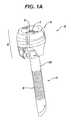
- FIG. 1Ais a perspective view of one embodiment of a trocar
- FIG. 1Bis an exploded view of the trocar of FIG. 1A ;
- FIG. 1Cis a cross-sectional view of a portion of the trocar of FIG. 1A ;
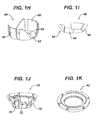
- FIG. 1Dis a bottom perspective view of an instrument seal assembly for use with the trocar of FIG. 1A ;
- FIG. 1Eis an exploded view of the instrument seal assembly of FIG. 1D ;
- FIG. 1Fis a perspective view of a channel seal of the trocar of FIG. 1A ;
- FIG. 1Gis a bottom perspective view of one embodiment of a scraper of a fluid remover assembly for use with the trocar of FIG. 1A ;
- FIG. 1His a perspective view of one embodiment of a sorbent wick of a fluid remover assembly for use with the trocar of FIG. 1A ;
- FIG. 1Iis a perspective view of a sorbent element of a fluid remover assembly for use with the trocar of FIG. 1A ;
- FIG. 1Jis a perspective view of a frame for housing the sorbent element of FIG. 1I ;
- FIG. 1Kis a perspective view of a lid portion of a fluid remover assembly for use with the trocar of FIG. 1A ;
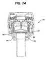
- FIG. 2Ais a cross-sectional view of a proximal portion of another embodiment of a trocar
- FIG. 2Bis an exploded view of the trocar of FIG. 2A ;
- FIG. 3Ais an exploded view of a portion of a trocar having a drop-in fluid remover assembly
- FIG. 3Bis an exploded view of the drop-in fluid remover assembly of FIG. 3A ;
- FIG. 3Cis a cross-sectional view of a trocar of FIG. 3A ;
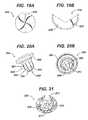
- FIG. 4Ais an exploded view of one embodiment of a scraper assembly for scraping fluid
- FIG. 4Bis a bottom perspective view the scraper assembly of FIG. 4A ;
- FIG. 4Cis a top perspective view of the scraper assembly of FIG. 4A ;
- FIG. 5Ais a perspective view of another embodiment of fluid remover assembly having a scraper nested within a sorbent element
- FIG. 5Bis top view of the fluid remover assembly of FIG. 5A ;
- FIG. 5Cis a cross-sectional view of the fluid remover assembly of FIG. 5A disposed within a trocar housing;
- FIG. 6Ais a cross-sectional view of a trocar having one embodiment of a scraper for scraping fluid away from a surgical instrument passed therethrough;
- FIG. 6Bis a cross-sectional view of a trocar having another embodiment of a scraper for scraping fluid away from a surgical instrument passed therethrough;
- FIG. 6Cis a cross-sectional view of a trocar having yet another embodiment of a scraper for scraping fluid away from a surgical instrument passed therethrough;
- FIG. 7is a cross-sectional view of another embodiment of a trocar housing having sorbent flapper doors positioned adjacent to a zero-closure seal;
- FIG. 8is a cross-sectional view of yet another embodiment of a trocar housing having wicking fingers coupled to a sorbent reservoir;
- FIG. 9is a cross-sectional view of one embodiment of a trocar housing having a sorbent element disposed therein;
- FIG. 10Ais a cross-sectional view of one embodiment of a zero-closure seal having extension members for wicking fluid
- FIG. 10Bis a transparent perspective view of the seal of FIG. 10A ;
- FIG. 11is an exploded view of another embodiment of fluid remover assembly having a sorbent element nested between first and second zero-closure seals;
- FIG. 12Ais a cross-sectional view of yet another embodiment of a sorbent element having two sorbent bars disposed within a zero-closure seal;
- FIG. 12Bis a transparent perspective view of the sorbent element and seal of FIG. 12A ;
- FIG. 13is an exploded view of one embodiment of a trocar housing having a scraper for scraping fluid away from a surgical instrument passed therethrough;
- FIG. 14is a cross-sectional view of one embodiment of a trocar cap having a scraper for scraping fluid away from a surgical instrument passed therethrough;
- FIG. 15Ais a top view of a trocar cap having another embodiment of a scraper for scraping fluid away from a surgical instrument passed therethrough;
- FIG. 15Bis a side perspective view of the trocar cap of FIG. 15A ;
- FIG. 16is an exploded view of one embodiment of a multi-layer seal having a sorbent element disposed between the layers;
- FIG. 17is a bottom perspective view of one embodiment of a trocar cap having a sorbent element disposed therein;
- FIG. 18Ais a bottom perspective view of one embodiment of a wicking element formed on a portion of a seal protector for creating between the seal protector and a seal;
- FIG. 18Bis a top perspective view of the portion of the seal protector of FIG. 18A ;
- FIG. 19Ais a top view of a multi-layer protective member having camming ribs
- FIG. 19Bis a top view of one layer of the protective member of FIG. 19A ;
- FIG. 20Ais a side perspective view of a deep cone instrument seal having wicking ribs formed on an external surface
- FIG. 20Bis a top perspective view of another embodiment of a deep cone instrument seal having wicking ribs formed on an internal surface
- FIG. 21is a perspective view of a multi-layer protective element having holes formed therein for receiving fluid
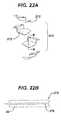
- FIG. 22Ais an exploded view of a multi-layer protective element
- FIG. 22Bis a cross-sectional view taken across line B-B of one of the protective elements of FIG. 22A ;
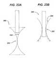
- FIG. 23Ais a side view of one embodiment of a seal having an hourglass configuration for scraping fluid off of a surgical instrument
- FIG. 23Bis a side view of the seal of FIG. 23A showing an instrument passed therethrough;
- FIG. 24Ais cross-sectional view of one embodiment of a trocar cannula having overlapping scrapers and a sorbent disposed therein;
- FIG. 24Bis an enlarged view of one of the scrapers and sorbents of FIG. 24A ;
- FIG. 25is a perspective view of another embodiment of a scraper for scraping fluid off of a surgical instrument shown passed therethrough;
- FIG. 26is a perspective view of another embodiment of a device for scraping fluid away from a surgical instrument
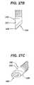
- FIG. 27Ais an exploded view of a trocar and removable tip for scraping fluid away from a surgical instrument
- FIG. 27Bis an assembled side view of a distal end of the trocar and removable tip of FIG. 27A ;
- FIG. 27Cis a perspective view of the removable tip and distal end of the trocar of FIG. 26B ;
- FIG. 28is a partially-transparent side view of one embodiment of wicking element having an hourglass shape
- FIG. 29is a perspective view of a trocar having a cannula with slots formed therein for wicking fluid out of the cannula;
- FIG. 30Ais a perspective view of another embodiment of a trocar having a proximal housing and a distal cannula;
- FIG. 30Bis a cross-sectional side view of the trocar of FIG. 30A ;
- FIG. 30Cis a perspective view of an instrument seal assembly, a channel seal, a fluid remover assembly, and an insufflation port of the trocar of FIG. 30A ;
- FIG. 30Dis a cross-sectional side view of the fluid remover and insufflation port of FIG. 30C ;
- FIG. 30Eis a perspective view of a fluid remover of FIG. 30C ;
- FIG. 30Fis an exploded view of the fluid remover of FIG. 30E showing a lid, scraper, crown, and sorbent;
- FIG. 30Gis a bottom perspective view of a scraper of FIG. 30F showing channels formed therein;
- FIG. 30His a cross-sectional view of one of the channels of the scraper of FIG. 30G ;
- FIG. 30Iis a top view of a lid of FIG. 30F ;
- FIG. 30Jis a bottom view of the lid of FIG. 33I ;
- FIG. 31is a bottom view of another embodiment of a lid for use with a fluid remover assembly
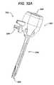
- FIG. 32Ais a perspective view of another embodiment of a trocar
- FIG. 32Bis a side perspective view of an instrument seal, a channel seal, a fluid remover, and an insufflation port of the trocar of FIG. 32A ;
- FIG. 32Cis a side view of the fluid remover and insufflation port of FIG. 32B ;
- FIG. 32Dis a side perspective view of the fluid remover of FIG. 32C .
- the present inventiongenerally provides methods and devices for maintaining clear visibility through a scoping device during surgical procedures, and in particular methods and devices are provided for removing fluid from an access device and/or surgical instrument passed, e.g., inserted and/or withdrawn, through an access device, and/or for preventing fluid from being transferred onto a scoping device passed through an access device.
- the methods and devicesare effective to remove fluid from an access device and/or surgical instrument as the instrument is being withdrawn from the access device, thus preventing the fluid from being deposited onto an instrument being inserted through the access device.
- the methods and devicescan be configured to remove fluid prior to and/or during insertion and/or removal.
- Fluidsinclude any substance that, when on a surgical instrument, can adversely affect the functioning of the instrument or a surgeon's ability to use it.
- Fluidsinclude any kind of bodily fluid, such as blood, and any kind of fluid introduced during a surgical procedure, such as saline. Fluids also include fluid/solid mixtures or fluids with particles (such as pieces of tissue) suspended or located therein, as well as viscous materials and gases.
- the various concepts disclosed hereincan be used with various surgical instruments during various procedures, but in certain exemplary embodiments the present invention is particularly useful during laparoscope procedures, and more particularly during procedures in which a scoping device, such as an laparoscope or endoscope, is passed through a surgical access device, such as a trocar, that provides a pathway from a skin incision to a body cavity.
- a scoping devicesuch as an laparoscope or endoscope
- a surgical access devicesuch as a trocar
- the methods and devices disclosed hereinutilize a fluid remover that is effective to remove fluid from an access device and/or surgical instrument passed therethrough.
- the fluid removercan have various configurations and it can function in various manners to remove fluid
- exemplary fluid removersinclude scrapers for scraping fluids, sorbents for sorbing fluid, and wicking elements for redirecting or wicking fluid away, e.g., by capillary action. Any combination of fluid removers can be provided, and the fluid removers can be disposed at various locations within an access device to remove fluid from portions of the access device and/or from surgical instruments, such as scoping devices, passed through the access device. The particular location of the fluid remover(s) can depend on the particular configuration of the access device and/or surgical instrument.
- the fluid removercan include one or more sorbents.
- the sorbentcan be any insoluble (or at least partially insoluble) material or mixture of materials that are capable of sorbing fluids or taking up fluids through a process of one or both of absorption and adsorption.
- a sorbent material or elementcan thus include any one of or combination of absorbent materials and/or elements and adsorbent materials and/or elements.
- the sorbentis formed from a hydrophilic material and/or includes a hydrophilic material to facilitate fluid receipt.
- the sorbentcan be coated using known coating techniques during manufacturing to render one or more portions of the sorbent hydrophilic.
- the sorbentcan be formed by an extrusion process in which, for example, the fibers can all extend longitudinally in a direction generally parallel to a longitudinal axis of the cylindrical tube, as shown in FIG. 30F .
- the fiberswill thus form a generally cylindrical, hollow tubular member, which can subsequently be cut to form a plurality of sorbents.
- a sidewall gap or cut-outcan also be made to form a C-shaped sorbent, or the sorbent can be formed to have a C-shaped configuration without the need to make any additional cuts. Exemplary shapes and configurations for the sorbent will be discussed in more detail below.
- a hydrophilic surfactantcan be applied to the sorbent, either prior to or after the sorbent is cut.
- hydrophilic materialcan also vary, and exemplary materials will be discussed in more detail below with respect to the scraper.
- the same hydrophilic materials used with the scrapercan also or alternatively be used with the sorbent.
- sorbentsthat are absorbents remove fluid through a process of absorption, similar to a sponge, in which a liquid diffuses into the volume and/or structure of the absorbent and becomes a part of that volume and/or structure.
- the sorbentcan pick up and retain a liquid distributed throughout its molecular structure causing the absorbent to swell.
- the liquidcan cause the solid structure to swell 50% of more.
- Typical absorbentsare at least 70% insoluble in excess fluid.
- Absorbentscan have any shape, size, and form known in the art as needed to stand alone and/or fit within, around, or throughout any component of a fluid remover and/or trocar.
- absorbentsinclude, but are not limited to, comminuted wood pulp fluff, cellulose fibers, polymeric gelling agents, hydrophilic non-wovens, cellulose, sodium polycrylate, cotton, polyethylene terephthalate, polyethylene, polypropylene, polyvinyl chloride, ABS, polyamide, polystyrene, polyvinyl alcohol, polycarbonate, ethylenemethacrylate copolymer, and polyacetal.
- an adsorbent materialcan include one or more insoluble materials (or at least partially insoluble) that can be coated by a liquid on their surface.
- the adsorbentcan be a structure formed from insoluble fibers. The structure can be porous, as voids or spaces can be located between the individual fibers.
- Adsorbentscan have any shape, size, and form known in the art as needed to stand alone and/or fit within, around, or throughout any component of a fluid remover and/or trocar.
- the adsorbentis molded to have a predetermined shape and size.
- Certain exemplary adsorbent materialsinclude, but are not limited to, oxygen-containing compounds, carbon-based compounds, and/or polymer based compounds, among others.
- adsorbent materialscan include silica gels, alumina, zeolites, activated carbon, graphite, cellulose, porous polymer matrices, perlite, metal hydroxides, metal oxidesellulose acetate, -butyrate and -nitrate, polyamide, polysulfone, vinyl polymers, polyesters, polyolefines and PTFE, as well as porous glass or glass ceramics, graphite oxide, polyelectrolyte complexes, alginate gel, etc.
- a trocarhaving one or more fluid removers disposed therein for removing fluid from portions of the trocar and/or from an instrument, such as a scoping device, passed therethrough.
- an instrumentsuch as a scoping device
- FIGS. 1A-1Cillustrate one exemplary embodiment of a trocar 2 .
- the trocar 2is generally in the form of a housing 6 having a proximal portion (also referred to herein as a proximal housing) that can house one or more sealing elements and a distal cannula 8 extending distally from the proximal housing 6 .
- the trocar 2defines a working channel 4 extending therethrough for introducing various instruments into a body cavity.
- a number of configurationsare available for the proximal housing 6 .
- the proximal housing 6has a generally cylindrical shape with a removable cap portion 5 and an inner sidewall 3 .
- An opening 7can be formed in the proximal end of the housing 6 , such that the opening 7 extends through the removable cap 5 and through the remainder of the housing 6 and is coaxial with the working channel 4 extending through the cannula 8 .
- the cannula 8can also have various configurations, and can include various features known in the art.
- the cannula 8has a generally elongate cylindrical shape and includes a series of annular ridges 9 formed on an external surface 10 thereof.
- the opening 7 extending through the proximal housing 6 and the cannula 8define the working channel 4 that is sized and configured to receive a surgical instrument.
- housing 6 and the cannula 8can be formed as a unitary structure or as two separate components that are mated to one another.
- the housing 6can also include other features, such as a stop-cock valve 13 for allowing and preventing the passage of an insufflation fluid, e.g. carbon dioxide, through the trocar 2 and into a body cavity.
- an insufflation fluide.g. carbon dioxide
- the distal cannula 8can be inserted through a skin incision and through tissue to position a distal-most end within a body cavity.
- the proximal housing 6can remain external to the body cavity, and various instruments can be inserted through the working channel 4 and into the body cavity.
- insufflationis provided through the trocar 2 to expand the body cavity to facilitate the surgical procedure.
- most trocarsinclude at least one seal disposed therein to prevent air from escaping.
- the trocar 2includes an instrument seal that forms a seal around an instrument disposed therethrough, but otherwise does not form a seal when no instrument is disposed therethrough; a channel seal (also referred to herein as a zero-closure seal) that seals the working channel 4 when no instrument is disposed therethrough; or a combination instrument seal and channel seal that is effective to both form a seal around an instrument disposed therethrough and to form a seal in the working channel 4 when no instrument is disposed therethrough.
- the trocar 2includes an instrument seal 14 and a separate channel or zero-closure seal 24 .
- various other seals known in the artcan be used including, for example, flapper valves, gel seals, diaphragm seals, etc.
- the instrument seal 14is generally in the form of a multi-layer conical seal 16 and a multi-layer protective member 18 disposed on a proximal surface 15 of the seal 16 .
- the multi-layer conical seal 16can include a series of overlapping seal segments 20 that are assembled in a woven arrangement to provide a complete seal body.
- the seal segments 20can be stacked on top of one another or woven together in an overlapping fashion to form the multi-layer seal 16 having a central opening 17 therein.
- the seal segments 20can be made from any number of materials known to those skilled in the art, but in an exemplary embodiment the seal segments 20 are formed from an elastomeric material.
- the seal segments 20can also be molded such that they have a varying thickness across the profile of the seal 16 . Varying the thickness across to the profile of the seal 16 can be effective to minimize leakage and reduce drag forces on the instrument.
- the multi-layer protective member 18can similarly be formed from a series of overlapping segments 22 that are disposed proximal to the overlapping seal segments 20 and that are configured to protect the seal segments 20 from damage caused by surgical instruments passed through the opening 17 in the seal 16 .
- the protective member 18can also be formed from various materials, but in certain exemplary embodiments the protective member 18 is formed from a molded thermoplastic polyurethane elastomer, such as PellethaneTM.
- the segments 20 , 22 that form the seal 16 and the protective member 18can be held together using various techniques known in the art. As shown in FIGS. 1D and 1E , the segments 20 , 22 are held together by several ring members that mate to engage the segments 20 , 22 therebetween. In particular, the protective member 18 is engaged between a crown 26 and a gasket ring 28 , and the seal 16 is engaged between the gasket ring 28 and a retainer ring 30 . Pins 32 are used to mate the ring members 26 , 28 and to extend through and engage the segments of the seal 16 and protective member 18 .
- the instrument seal 14can be disposed at various locations within the trocar 2 .
- the instrument seal 14is disposed in the cap 5 of the trocar 2 at a location just distal of the proximal opening 7 and proximal of a channel seal, as discussed in more detail below.
- an instrumentcan be passed through the center of the seal assembly and the seal segments 20 , 22 can engage and form a seal around an outer surface of the instrument to thereby prevent the passage of fluids through the seal 14 .
- the openingwill not form a seal in the working channel 4 , however other configurations in which a seal is formed when no instrument is disposed therethrough are also conceivable.
- the zero-closure seal in the illustrated embodimentis shown in more detail in FIG. 1F , and as shown the illustrated zero-closure seal is in the form of a duckbill seal 24 .
- the seal 24is configured to form a seal in the working channel 4 when no instrument is disposed therethrough to thus prevent the leakage of insufflation gases delivered through the trocar 2 to the body cavity.
- the duckbill seal 24has a generally circular flange 34 with a sidewall 36 extending distally therefrom.
- the shape of the sidewall 36can vary, but in the illustrated embodiment, the sidewall 36 includes opposed flaps 35 that extend at an angle toward one another in a distal direction and that come together at a distal end to form a seal face 38 .
- the opposed flaps 35are movable relative to one another to allow the seal face 38 to move between a closed position, in which no instrument is disposed therethrough and the seal face 38 seals the working channel 4 of the trocar 2 , and an open position in which an instrument is disposed therethrough.
- the sealcan include various other features, as described in more detail in U.S. application Ser. No. 11/771,263, entitled “Duckbill Seal with Fluid Drainage Feature,” filed on Jun. 29, 2007, which is hereby incorporated by reference in its entirety.
- a fluid removercan be disposed within the trocar 2 to remove fluid from a seal and/or from a surgical instrument extending through the seal.
- the illustrated trocar 2includes a fluid remover assembly 40 that is disposed within the proximal housing 6 of the trocar 2 at a location distal of the duckbill seal 24 .
- the fluid removal assembly 40includes a scraper for scraping fluid off of a surgical instrument passed through the working channel 4 in the trocar 2 , and a sorbent for sorbing removed fluid.
- the scrapercan also include a wicking feature for wicking fluid away from the opening in the scraper, and/or the sorbent can include a wicking feature for wicking fluid away from the scraper.
- the components of the fluid remover assembly 40are shown in more detail in FIGS. 1G-1K , and as shown the assembly generally includes a lid 42 ( FIG. 1K ), a scraper 44 ( FIG. 1G ), a sorbent wick 46 ( FIG. 1H ), sorbent cartridges 48 ( FIGS. 1I ), and a housing or frame 50 (FIG. 1 J).
- the fluid remover assembly 40When fully assembled, the fluid remover assembly 40 is configured to scrape fluid off of surgical instruments passing through the working channel 4 of the trocar 2 , to wick the scraped fluids away, and to sorb them, thereby preventing the fluids from being redeposited on the instrument upon reinsertion through the working channel.
- the scraper 44can have a variety of configurations, but in an exemplary embodiment, as shown, the scraper has a generally planar configuration with a circular shape.
- a central opening 52is formed through a central portion thereof and is sized and configured to receive a surgical instrument therethrough. In use, the central opening 52 can be coaxial with openings in the instrument and channel seals.
- the scraper 44can be formed from various materials, but in an exemplary embodiment the scraper is formed from polyisoprene to allow the scraper 44 to engage and scrape fluid off of any instrument passed therethrough. As further shown in FIG.
- a distal-facing surface 54 of the scraper 44can include a plurality of channels 56 formed therein and extending radially outward from the central opening 52 , or from a location just radially outward but adjacent to the central opening 52 .
- the channels 56can be configured such that fluid scraped off of an instrument by the central opening 52 will flow into the channels 56 and thereby be wicked away from the opening 52 .
- the fluid remover assembly 40can also include a sorbent wick 46 .
- the sorbent wick 46has a generally planar circular portion 62 with a central opening 58 formed therethrough.
- the central opening 58can have a diameter slightly larger than a diameter of the central opening 52 in the scraper 44 , and it can be configured to be positioned coaxial with the opening 52 in the scraper 44 .
- the sorbent wick 46can also include one or more sidewalls 60 extending from the planar circular portion 62 . The illustrated sidewalls 60 extend proximally, however they can extend distally depending on the particular configuration of the wick 46 .
- the sidewalls 60can be configured to sit within the inner sidewall 3 of the trocar housing 6 .
- the sorbent wick 46can wick and sorb fluid away from the central opening 52 in the scraper 44 , and it can deliver the fluid to the sorbent cartridges 48 , as discussed in more detail below.
- the sorbent wick 46as well as various other sorbent members disclosed herein, can be formed from a variety of sorbent materials as described above.
- the sorbent cartridges 48are shown in more detail in FIG. 1I , and as shown the cartridges 48 each have a generally semi-circular shape with a width, as measured from an internal surface 64 to an external surface 66 , that decreases in a proximal to distal direction to form wedge-shaped members 68 . Together, the cartridges 48 can have an annular configuration. In use, the cartridges 48 can sorb fluid from the sorbent wick 46 , thereby storing the fluid at a location away from any instrument passed through the working channel 4 .
- the cartridges 48can be contained within the trocar 2 by a housing or frame 50 , as shown in FIG. 1J .
- the frame 50can have a generally cylindrical configuration with an opening 78 extending therethrough, and a plurality of ridges 70 protruding radially outward and extending axially along an outer surface 72 thereof. Each sorbent cartridge 48 can be seated between two ridges. In use, the frame 50 can be particularly advantageous as it can protect the sorbent from being contacted by instruments passing through the working channel.
- the scraper 44When fully assembly, the scraper 44 can be seated within the sorbent wick 46 , which can rest on top of the frame 50 that holds the sorbent cartridges 48 .
- the lid 42shown in FIG. 1K , can be seated on top of the scraper 44 and within the sorbent wick 46 , and the lid 42 can lock onto the frame 50 , thereby holding the fluid remover assembly 40 together.
- the entire assembly 40can be seated within the proximal housing 6 of the trocar 2 just distal of the duckbill seal 24 .
- any fluid on the instrumentwill be scraped off of the sidewalls of the instrument by the scraper 44 .
- the fluidwill flow through the channels 56 and/or be wicked away from the opening 52 by the sorbent wick 46 , which delivers the fluid to the sorbent cartridges 48 .
- the fluidwill be prevented from being deposited onto the instrument seal 14 , thereby preventing the fluid from being transferred from the instrument seal 14 back onto the instrument upon reinsertion.
- FIGS. 2A-2Billustrate yet another embodiment of a fluid remover assembly 80 that is similar to the embodiment shown in FIG. 1A .
- the proximal housing 79 of the trocarhas a frame 82 that is molded into the inner sidewall 81 of the housing 79 for directly seating a sorbent, a scraper, and a lid, thereby eliminating the need for the frame 50 of FIG. 1J .
- a single sorbent element 86is also provided, rather than a sorbent wick and separate sorbent cartridges.
- the sorbent element 86 in this embodimenthas a generally cylindrical configuration with a distal portion 88 that tapers inward on an outer surface 87 thereof to conform to the inner surface 81 of the proximal housing 79 of the trocar.
- a recess 90can be formed around an inner surface 92 of a proximal end 93 of the sorbent element 86 to seat a scraper 94 , which can have a configuration that is the same as or similar to the scraper 44 described above with respect to FIG. 1G .
- the recess 90can engage an outer perimeter 96 of the scraper 94 such that the channels 56 on the scraper 94 can deliver fluid away from the opening 52 in the scraper 94 to the sorbent element 86 surrounding the scraper 94 .
- a cap 98can sit on top of the scraper 94 and can include a flange 99 that extends around the proximal end 93 of the sorbent element 86 .
- the cap 98can engage the inner sidewall 81 of the proximal housing 79 of the trocar to retain the scraper 94 and sorbent element 86 therein at a location just distal of the duckbill seal 24 .
- instruments passed through the working channel 4 of the trocarwill be engaged by the scraper 94 , which scrapes fluid off of the outer surface of the instrument.
- the fluidis wicked away from the opening 52 in the scraper 94 by the channels 56 , which deliver the fluid to the sorbent element 86 surrounding the scraper 94 .
- the fluidwill be prevented from being deposited onto the seals, and in particular the instrument seal 14 , thereby preventing the fluid from being transferred from the instrument seal 14 back onto the instrument upon reinsertion.
- FIGS. 3A-10Billustrate additional exemplary embodiments of fluid removers, e.g., scrapers, sorbents, and wicking elements, or combinations thereof.
- the fluid removersare all located distal of the channel seal, e.g., duckbill seal or other zero-closure seal, and distal of the instrument seal 14 .
- the particular location of the fluid removercan vary and the fluid removers can be positioned anywhere within the trocar.
- FIGS. 3A-3Cillustrate one embodiment of a fluid remover assembly 100 having a scraper and a sorbent.
- the fluid remover assembly 100can include a stabilization cup 106 coupled to a flange 108 .
- the stabilization cup 106can be formed from a sorbent material and the flange 108 can seat the cup 106 within the proximal housing 6 of the trocar 2 , as shown in FIG. 3C .
- a scraper element in the form of a scraper disc 102can be positioned between the flange 108 and the stabilization cup 106 , and a sorbent ring 104 can be coupled to a distal surface of the scraper disc 102 .
- the scraper disc 102can have a central opening 105 extending therethrough and configured for scraping fluid off of surgical instruments passed through the working channel 4 of the trocar 2 .
- fluidcan be scraped by the scraper disc 102 and sorbed by the sorbent ring, as well as by the stabilization cup.
- the flange 108 , scraper disc 102 , and sorbent ring 104can each optionally include cut-outs 110 to fit around the stop-cock 13 associated with the trocar 2 .
- the fluid remover assembly 100can be formed as a drop-in unit that fits within the proximal housing 6 of the trocar 2 . As shown in FIG.
- the assembly 100can be seated in a distal portion of the proximal housing 6 at a location just distal of the duckbill seal 24 .
- the fluid remover assembly 100will thus remove fluid from instruments passed through the working channel 4 of the trocar, thereby preventing fluid from being deposited onto the seals, and in particular the instrument seal 14 , and/or redeposited onto instruments passed through the working channel 4 .
- FIGS. 4A-4Cillustrate another embodiment of a fluid remover assembly 114 that is similar to the assembly shown in FIGS. 3A-3C , however in this embodiment the assembly 114 does not include a stabilization cup.
- the fluid remover assemblyincludes a substantially planar circular scraper disc 116 having a central opening 115 for receiving a surgical instrument.
- the scraper disc 116can be seated within a flange or retainer ring 118 configured to be positioned within the proximal housing of a trocar.
- a sorbent ring 120can be positioned adjacent to a distal surface 117 of the scraper disc 116 and it can act to sorb any fluid that is scraped off of instruments passed through the scraper disc 116 .
- the flange 118When disposed within a trocar, the flange 118 can act as a support structure to hold the scraper disc 116 and the sorbent ring 120 in a fixed position within the proximal housing. While the position can be distal to the duckbill seal, as indicated above the assembly can be located at various other portions within the trocar, including between the duckbill seal and the instrument seal, proximal to the instrument seal, or within any portion of the cannula.
- a fluid remover assembly 122can have a generally conical configuration with a scraper 124 having a proximal generally planar flange 125 and a conical body 126 extending distally therefrom and defining a central opening 128 .
- the conical body 126can have a plurality of slits 127 extending proximally from a distal end thereof and designed to reduce insertion and withdrawal forces on a surgical instrument passed therethrough.
- the conical body 126can be surrounded by a conical sorbent element 130 such that the conical body 126 is nested within the conical sorbent element 130 .
- the flange 125can be seated within the proximal housing 6 just below the duckbill seal 24 and it can mate to or engage the inner sidewall of the housing 6 to retain the fluid remover assembly therein.
- the scraper 124can engage and scrap fluid off of the instrument and the sorbent element 130 can sorb the fluid.
- a size or diameter of a flangecan be adjusted as needed, or the flange can be removed, to seat the fluid remover assembly at other locations within the trocar.
- FIGS. 6A-6Cillustrate additional embodiments of conical scrapers 132 a, 132 b, 132 c that are similar to the scraper 124 described above and shown in FIGS. 5A-5C .
- the scrapers 132 a, 132 b, 132 c in FIGS. 6A-6Care positioned distal to the duckbill seal 24 .
- Such a configurationcan prevent fluid on instruments being inserted and/or withdrawn from being deposited onto the duckbill seal, as well as the more-proximally located instrument seal 14 .
- each scraper 132 a, 132 b, 132 ccan be made from a pliable material and can include at least one slit formed therein and configured to allow the scrapers 132 a, 132 b, 132 c to radially expand.
- a variety of configurationsare available for the slit(s).
- a single slit 134extends diagonally around the scraper 132 a such that the slit 134 follows the shape of the cone.
- multiple slits 137extend proximally from the distal end of the cone and terminate at a location 139 just distal to the proximal end.
- each scraping segment 138can also include a notch or cut-out 140 formed in an outer surface at the distal end thereof to allow the segment 138 to expand and contact as instruments are passed therethrough.
- FIG. 6Cillustrates another exemplary embodiment of a cone shaped scraper 132 c. Similar to the scraper 132 b shown in FIG. 6B , the scraper 132 c includes several slits 142 that extend proximally from the distal end thereof.
- the slits 142increase in width in a distal to proximal direction such that each scraping segment 143 has a distal end 144 with a width that is greater than a width of a proximal end 145 thereof.
- the slit(s) 134 , 137 , 142 formed in the scrapers 132 a, 132 b, 132 callow the scrapers to radially expand as a surgical instrument is passed therethrough, thus accommodating instruments of various sizes while still being effective to scrape fluid off of the instruments.
- FIG. 7illustrates another embodiment of a fluid remover positioned just distal of a channel seal, e.g., duckbill seal 150 , in a proximal housing of a trocar.
- the fluid removeris in the form of sorbent flapper doors 152 .
- the flapper doors 152can have various shapes and sizes, and they can be formed from any number of components.
- the flapper doors 152can be in the form of two sidewalls 153 that are movable relative to one another.
- the sidewalls 153can have a profile that is similar to the profile of the duckbill seal 150 .
- the flapper doors 152can have a shape that corresponds to the shape of the duckbill seal 150 .
- the flapper doors 152can be seated inside the proximal housing 6 and attached to the housing 6 by any attachment means known in the art, including by mechanical means, adhesives, etc.
- the flapper doors 152can define an opening 154 therebetween for receiving a surgical instrument, and the opening 154 can be positioned just distal of the seal face 151 .
- the flapper doors 152can move from a closed or substantially closed position to an open position as an instrument is passed through the duckbill seal 150 and the flappers door 152 .
- the doors 152can contact and engage the surgical instrument as it is being passed therethrough to sorb fluids off of the instrument.
- the flapper doors 152can also sorb any excess fluid that is scraped off of the instrument by the duckbill seal 150 and that falls distally from the duckbill seal 150 .
- the fluid removercan be in the form of a wicking element rather than a sorbent.
- the wicking elementis in the form of first and second wicking fingers 160 a, 160 b that are coupled to opposed outer edges 162 of the seal face 161 on the duckbill seal 163 .
- the wicking fingers 160 a, 160 bcan be in the form of elongate members that follow the natural shape of the inner sidewall 165 of the proximal housing 6 of the trocar 2 so that fluid will run naturally down the fingers 160 a, 160 b.
- the wicking fingers 160 a, 160 bcan also include a sorbent reservoir 164 disposed on a distal end thereof.
- the sorbent reservoir 164 on each finger 160 a, 160 bis in the shape of ring seated within the proximal housing 6 and effective to sorb the fluids wicked away from the duckbill seal 163 by the wicking fingers 160 a, 160 b.
- the sorbent reservoir 164can, however, have various other configurations such as ring segments. In use, as fluids are deposited on the duckbill seal 163 by instruments passing therethrough, the fluid will naturally flow to outer corners or edges of the seal face 161 .
- the surface difference between the wicking fingers 160 a, 160 b and the duckbill seal 24will cause fluid to flow from the seal 163 to the fingers 160 a, 160 b and down the fingers 160 a, 160 b into the sorbent reservoir 164 .
- the wicking fingers 160 a, 160 bcan be formed integrally with the duckbill seal 163 or can simply be in close contact with sealing face 161 of the duckbill seal 163 .
- FIG. 9illustrates another embodiment of a fluid remover that is positioned distal of a zero-closure seal. Similar to the embodiment shown in FIG. 7 , the fluid remover is in the form of a sorbent. However, in this embodiment the sorbent is a sorbent grommet 172 .
- the grommet 172can have a generally circular or conical configuration with an opening 173 formed therethrough, as shown, but it can have any number of other geometries to facilitate passage of an instrument therethrough.
- the grommet 172can also include multiple slits 174 formed therein and extending radially outward from the opening 173 to reduce insertion and withdrawal forces on an instrument being passed therethrough.
- the grommet 172can be seated within a distal portion of the proximal housing 6 of the trocar, just distal of the duckbill seal 166 , and the opening 173 can be positioned coaxial with the working channel 4 . As a surgical instrument is passed therethrough, the grommet 172 will contact the instrument and sorb any fluid on the instrument. The grommet 172 can also sorb any fluid that drips off of the duckbill seal 166 as the seal 166 scrapes the instrument.
- FIGS. 10A and 10Billustrate another embodiment of a duckbill seal 176 in which the seal face 168 is extended distally and expanded in width to cause the outer ends of the seal face 168 to contact the inner sidewall 169 of the proximal housing 6 of the trocar, thereby forming a wicking element.
- the seal face 168will scrape fluid off of the instrument. The fluid will naturally run outward toward the outer-most edges of the seal face 168 .
- the housing 6can optionally include a sorbent disposed therein for sorbing the fluid wicked away from the seal.
- FIG. 11illustrates another embodiment of a modified zero-closure seal 186 .
- a sorbent element 180is nested inside of the duckbill seal 177
- a second duckbill seal 178is nested within the sorbent element 180 .
- the nested sorbent 180 and the nested duckbill seal 178can have two sealing walls, 182 , 184 similar to the duckbill seal 177 , that meet at a seal face that is configured to form a seal when no instrument is disposed therein and that are configured to open when a surgical instrument is passed therethrough.
- the body of the nested sorbent 180 and the nested duckbill 178can each have a profile similar or identical to the duckbill seal 177 , except smaller in size to all fit for a nested configuration.
- the components 177 , 178 , 180can merely be seated within one another, or they can be attached to one another using various attachment mechanisms known in the art, including a press fit, glue, etc. In use, the seal face of all three components will contact a surgical instrument as it is passed through the seal assembly. The sorbent 180 will thus sorb any fluid on the instrument, as well as fluid scraped off of the instrument by the duckbill seal 177 and the nested duckbill seal 178 .
- FIGS. 12A-12Billustrate another embodiment of a modified zero-closure seal 190 .
- the duckbill seal 191includes two sorbent bars 192 disposed therein and extending thereacross.
- the sorbent bars 192can be positioned to extend substantially parallel to the seal face 193 , or to extend substantially perpendicular as shown.
- the seal 190can also include a sorbent ring 194 positioned around an inner sidewall 193 of the duckbill seal 191 and in contact with the sorbent bars 192 .
- the sorbent ring 194can provide a reservoir for fluid collected by the sorbent bars 192 .
- the sorbent bars 192will contact and engage a surgical instrument as it is passed through the duckbill seal 191 , and will thus sorb fluid away from the surgical instrument.
- the various fluid remover embodiments disclosed hereincan be located anywhere within a trocar or other access device, including distal of a channel seal, between a channel seal and an instrument seal, or proximal of an instrument seal.
- the position of the fluid removercan also vary relative to an insufflation port, as will be discussed in more detail below.
- the fluid removerscan also be formed integrally with the seal(s) and/or portions of the housing, and any combination of fluid removers can be used.
- FIGS. 13-22Billustrate various exemplary embodiments of fluid removers that are formed integrally or incorporated into an instrument seal, or located adjacent to an instrument seal and thus proximal to a channel seal.
- the fluid remover 200is in the form of a combination scraper and sorbent.
- the fluid remover 200includes a generally planar circular scraper disc 202 having an opening 204 formed therethrough and configuration to be positioned coaxial with the working channel 4 in the trocar 2 .
- the opening 204can be sized and configured to form a seal around an instrument passed therethrough.
- the fluid remover 200can also include a sorbent disk 206 disposed concentrically around the opening 204 in the scraper 202 . In use, the scraper 202 will scrape fluid off of instruments passed therethrough, and the sorbent disk 206 will sorb the scraped fluid.
- the fluid remover 200can be disposed within the proximal housing 6 of the trocar 2 using various techniques, but as shown in FIG. 13 the fluid remover 200 is configured to be engaged between the removable cap 5 and the distal portion of the proximal housing 6 of the trocar 2 . As a result, the scraper 202 and sorbent 206 will be positioned in alignment with the working channel 4 extending through the housing 6 , and will also be positioned between the proximal instrument seal and the distal channel seal.
- FIG. 14illustrates another embodiment of a fluid remover 210 having a combination scraper and sorbent, however in this embodiment the fluid remover 210 is fully disposed within the removable cap 5 containing the instrument seal.
- a scraper 212can be cone shaped and can be positioned just distal of the instrument seal. In other embodiments the scraper 212 can be planar. The scraper 212 can also replace or function as the instrument seal.
- a sorbent ring 214can be positioned concentrically around and in contact with an opening 216 in the distal end of the of the conical scraper 212 . As a result, the sorbent ring 214 will sorb any fluid scraped away from a surgical instrument extending through the scraper 212 .
- the fluid removercan be in the form of a scraper that is part of the instrument seal 218 .
- the instrument seal 218is a multi-layer seal having the protector disposed on a proximal surface thereof, as previously described with respect to FIG. 1E .
- the scrapercan be in the form of a second protector 222 that is disposed distal to the multi-layer seal segments.
- the second protector 222can have the same configuration as the protector of FIG. 1E , however the second protector 222 can define an opening 224 that is configured to contact and engage a surgical instrument passed through the seal 218 . Accordingly, in use, the second protector 222 can engage and scrape fluid away from instruments passed through the seal 218 .
- the fluid removercan be in the form of a multi-layer sorbent that is positioned between the multiple layers 20 of the seal 16 , as shown, or that is positioned between the multiple layers 22 of the seal protector 18 .
- the sorbentcan be in the form of multiple sorbent sheets 232 that are layered in between the layers of the seal 16 (or seal protector 18 ).
- the sheets 232will sorb any fluids scraped off of the instrument by the seal 14 , thereby preventing fluid from accumulating around the opening of the seal 14 and being reapplied to a surgical instrument as it is reinserted therethrough.
- the sorbent sheets 232can be effective to sorb fluid, as well as to interrupt surface tension and/or capillary action between the seal and the protector. Thus, there should be no fluid in or near the seal opening and/or protector opening that will be able to touch or collect on an instrument being passed therethrough.
- FIG. 17illustrates another embodiment of a sorbent fluid remover.
- the sorbentis in the form of a grommet 242 having a configuration similar to the grommet 172 previously described with respect to FIG. 9 .
- the grommet 242is positioned adjacent to a distal surface 244 of the instrument seal 14 , rather than the zero-closure seal 24 .
- the grommet 242can be disposed concentrically around a distal opening 246 formed in the removable cap 5 such that instruments passed through the instrument seal 14 will contact the grommet 242 , which will sorb fluids off of the instrument.
- the grommet 242can also sorb any fluid that is scraped from or drips from the instrument seal 14 .
- a wicking elementis formed integrally with the multi-layer seal protector 18 previously described with respect to FIG. 1E .
- the multi-layer seal 16can have a natural shape that is slightly conical and it can include an opening sized to receive an instrument therethrough.
- the protector 18likewise has an opening, however in the embodiment shown in FIGS. 18A and 18B the length of a protector 240 is decreased to thereby increase the diameter of the opening defined by the protector 18 .
- the protector 240will have an opening that is larger than the opening in the seal 16 to create a flattened profile against the conical shape of the seal 16 , thereby creating a gap between the protector 240 and seal 16 .
- the gapwill prevent fluids from collecting between the layers 20 of the seal 16 and will allow the protector 240 to wick fluids away from the opening of the seal 16 .
- the protector 240will prevent fluid from being squeezed from between the seal 16 and protector 240 and onto an instrument.
- the multi-layer seal protector 248has a wicking element in the form of camming ribs 250 disposed on a surface of each individual protector layer 249 so that the ribs 250 create pockets between the layers for wicking away and retaining fluid scraped off of instruments by the instrument seal.
- the ribs 250are offset by 90 degrees, although other geometries are possible as will be appreciated by those skilled in the art.
- the ribs 250can be disposed on a top or proximal surface of the protector.
- the instrumentwill contact the ribs 250 to thereby cam open the protector 248 and the seal, preventing the surgical instrument from coming into contact with the surface of the protector 248 and/or the seal.
- the ribs 250can be disposed on a bottom or distal surface of the protector, thereby creating a gap between the protector 248 and the seal to prevent capillary action and the trapping of fluid between the seal and protector 248 .
- FIGS. 20A and 20Billustrate another embodiment of an instrument seal 254 having ribs for wicking fluid away from an opening in the seal 254 .
- the instrument seal 254is in the form of a deep cone seal having a flange 260 with a conical sidewall 262 extending distally therefrom.
- a distal portion 264 of the conical sidewall 262tapers inward to define an opening 258 in the distal end 264 of the seal 254 .
- the sidewall 262can include one or more ribs 266 formed on an external surface 261 thereof and extending between proximal and distal ends of the sidewall 262 , terminating at the opening 258 .
- the external ribs 266can be effective to wick fluid away from the opening 258 in the seal 254 .
- the ribs 266are formed on the inner surface 268 of the sidewall 262 and extend between proximal and distal ends of the sidewall 262 , terminating at the opening 258 .
- the ribs 266will thus have a camming effect, causing any instrument inserted through the seal 254 to contact the ribs 266 to cam open the seal 254 , rather than contacting an inner surface 268 of the seal 254 .
- the multi-layer seal protector 269can include a plurality of holes 270 formed in the individual layers 271 of the protector 269 to form a wicking element for wicking fluid away from the seal.
- the holes 270act to wick away fluid from the seal and from the opening in the seal. The fluid can be retained within the holes 270 by surface tension so that an instrument passed through the seal will not contact the fluid retained in the holes 270 .
- the protector segments 272can include surface features, such as a roughened surface 276 , formed on the distal surface thereof. As shown in FIG. 22B , when the protector segments 272 are positioned against the seal segments 20 , the roughened surface 276 will create a gap that separates the protector 273 from the seal, thus providing a path for fluid to wick away from the opening in the seal and from between the protector 273 and the seal.
- FIGS. 23A-23Billustrate another embodiment of a seal 280 that is configured to remove fluid.
- the seal 280has an hourglass configuration such that the seal 280 is a combination trocar and instrument seal.
- the seal 280is effective to both form a seal within the working channel of the trocar when no instrument is disposed therethrough and to form a seal around an instrument disposed therethrough.
- the hourglass shape of the seal 280allows a central portion 282 of the seal 280 , which in a natural state is in a closed configuration as shown in FIG. 23A , to open and engage an instrument passed therethrough, as shown in FIG. 23B , and thereby scrape any fluid off of the instrument.
- the hourglass configuration of the seal 280is also advantageous in that it will accommodate instruments of various sizes.
- the central portion 282can also move or float relative to the central axis of the working channel in the trocar, thus accommodating off-axis instruments.
- FIGS. 24A-29illustrate various other exemplary embodiments of fluid removers. While certain embodiments are described as being disposed or formed in the cannula, a person skilled in the art will appreciate that, as with previous embodiments, the embodiments of FIGS. 24A-29 can likewise be disposed at various locations within a trocar and that various combinations of fluid removers can be used.
- the fluid removeris in the form of a plurality of scraper elements that extend at least partially across the working channel 4 of the cannula 8 .
- the scraper elementscan be relatively thin and can take the shape and form of wipers 292 , as best shown in FIG. 24B , that will scrape or squeegee fluid off of a surgical instrument passed through the cannula 8 .
- the wipers 292can be fixedly or hingedly coupled to an inner sidewall 294 of the cannula 8 , and they can be flexible to accommodate instruments of various sizes, and to allow both insertion and withdrawal of the instruments.
- the cannula 8can also include any number of wipers 292 , and the wipers 292 can be spaced apart from one another, or they can be in a stacked configuration.
- the wipers 292can have a conical configuration such that each wiper 292 extends around the entire inner diameter of the cannula 8 .
- the wipers 292can be formed into individual segments that are positioned a distance apart from one another, e.g., approximately 90 degrees apart within the interior surface 294 of the cannula 8 .
- the segmentscan be layered within the cannula 8 so that different parts of the surgical instrument come into contact with the wipers 292 at different heights as the instrument is being passed therethrough.
- the wipers 292can also be in contact with a sorbent element 296 , or include a sorbent portion, such that the collected fluid drips onto or is wicked into the sorbent material and away from possible contact with a reinserted instrument.
- the sorbent element 296is located adjacent to the inner sidewall 294 , and thus radially outward from the wiper body 292 .
- the sorbent elements 296can be formed into a wall of the cannula 8 , so that the cannula 8 is partially formed from the sorbent elements 296 .
- the sorbent elements 296can also be formed within grooves in the cannula wall and/or can be adhered directly to the cannula wall by any attachment mechanism known in the art, for example an attachment ring 297 .
- an attachment mechanismknown in the art, for example an attachment ring 297 .
- FIGS. 25illustrates another exemplary embodiment of a scraper 300 .
- the scraper 300is substantially cone shaped increasing in diameter in a distal direction.
- a proximal end 302 of the scraper 300includes an opening 304 formed therethrough, and a fluid collection member is formed at a distal end 306 thereof and extends inwardly.
- the fluid collection membercan have a variety of configurations and can be generally configured to collect fluid scraped by the scraper 300 .
- the fluid collection membercan be in the form of a substantially C-shaped lip 308 extending inwardly from the distal end 306 of the scraper 300 .
- the fluid collection membercan also optionally be sorbent thereby enabling the fluid collection member to both collect and sorb fluid scraped by the scraper.
- the scraper 300can be formed from a pliable material such that it can radially expand to engage a surgical instrument extending therethrough. In use, the narrow proximal end of the scraper 300 can engage a surgical instrument passed therethrough to thereby scrape fluid away from the instrument. The fluid scraped away from the instrument will run down an inner surface 310 of the scraper 300 and be collected and/or sorbed by the fluid collection member disposed at the distal end 306 of the scraper 300 . While the scraper 300 is generally indicated as being disposed in the cannula 8 , the scraper 300 can likewise be disposed anywhere within the trocar 2 , including in the proximal housing 6 .
- FIG. 26illustrates another exemplary embodiment of a scraper 312 .
- the scraper 312includes first and second rotatable members 314 a, 314 b that are configured to rotate and engage a surgical instrument as the instrument is passed therethrough.
- the first and second rotatable members 314 a, 314 bcan have a variety of shapes and sizes.
- the first and second rotatable members 314 a, 314 bare spool shaped. The spools can be configured such that the geometry of second member 314 b complements that of the first member 314 a.
- the first member 314 aincludes a substantially spherically shaped central portion 316 that corresponds with a concave cut-out 318 in the second member 314 b.
- the geometry of the spoolscan have several shapes including, but not limited to, straight sided cylindrical, c-shaped, and indented cylindrical.
- the first and second rotatable members 314 a, 314 bcan be positioned at a variety of locations in the cannula, or within the proximal housing of a trocar, and they can be formed from a variety of materials including, but not limited to, rigid, pliable, and sorbent materials. In use, the rotatable members 314 a, 314 b can rotate and engage a surgical instrument passed therethrough to thereby scrape and optionally sorb fluid away from the instrument.
- FIGS. 27A-27Cillustrate another embodiment of a fluid remover in the form of a removable tip or sleeve 322 that can be removable coupled to a distal end 324 of the cannula 8 .
- the sleeve 322is in the form of a generally cylindrical housing with a tapered distal end 326 , similar to the distal end 324 of the cannula 8 .
- a proximal end 328 of the sleeve 322can be sized to fit over and engage the distal end of the cannula 8 , e.g., by interference fit, and the distal end of the housing can include an opening 330 formed therein and sized to receive a surgical instrument therethrough.
- the sleeve 322can be formed from a compliant or expandable material to allow the opening in the sleeve 322 to radially expand as an instrument is passed therethrough.
- compliant materialsinclude, but are not limited to, polyisoprene, pellathane, and silicone.
- an hourglass shaped seal 340similar to the seal 280 described with respect to FIGS. 23A-23B is provided, however the seal 340 includes a wicking element in the form of one or more cut-outs or slots 342 formed in the central, reduced-diameter portion 344 . Similar to the seal 280 previously described with respect to FIG. 23A and 23B , the hourglass shape will allow the central portion 344 to scrape or squeegee fluid from a surgical instrument passed therethrough. The cut-outs or slots 342 will allow the scraped fluid to be wicked through the slots 342 to an exterior surface 346 of the seal 340 .
- the wicking elementcan take the form of a plurality of slots 350 formed in the working channel 4 of a cannula 352 .
- the slots 350can have any size and shape sufficient to transfer fluid disposed on an inner surface of the cannula 352 to an outside surface 354 of the cannula 352 .
- any fluid that drips down the inner surface of the cannula 352will be transferred to the external surface 354 of the cannula 352 through the slots 350 .
- FIGS. 30A-30Jillustrate another embodiment of a trocar 400 having a fluid remover 430 disposed therein.
- the trocar 400has a proximal housing 402 and a distal cannula 404 with a working channel 408 formed through and extending between proximal and distal ends 400 a, 400 b thereof.
- the housing 402can include one or more seals that are effective to seal the working channel 408 , i.e., to prevent the escape of insufflation, when no instrument is disposed therethrough and/or when an instrument is disposed therethrough. As shown in FIGS.
- the housing 402includes a proximal instrument seal, in the form of a multi-layer seal 412 , that is effective to form a seal around an instrument inserted therethrough, and a distal channel seal, such as a duckbill seal 410 , that is effective to seal the working channel when no instrument is inserted therethrough.
- a proximal instrument sealin the form of a multi-layer seal 412
- a distal channel sealsuch as a duckbill seal 410
- Such a duckbillis particularly useful as it has a low profile and has fluid drainage features that can assist in further preventing fluid from being redeposited onto instruments inserted through the seals.
- a person skilled in the artwill appreciate that any number, type, and configuration of channel and/or instrument seals can be positioned within the housing 402 at various locations.
- the housingcan also include an insufflation port 406 is formed in the housing 402 for providing an insufflation gas to the working channel 408 .
- the housing 402can include a fluid remover 430 positioned therein and configured to remove fluid from a surgical instrument inserted therethrough.
- the fluid remover 430can have an opening 470 formed through a center portion thereof, in axial alignment with the working channel 408 , for receiving a surgical instrument.
- the opening 470can be effective to remove fluid from a surgical instrument upon insertion and/or withdrawal therethrough.
- the fluid remover 430is preferably positioned distal to the seals 412 , 410 so that fluid collected on the instrument when disposed in a body cavity can be removed from the surgical instrument before it is withdrawn through the seals 412 , 410 , thus preventing the fluid from being deposited on the seals and thereafter deposited onto an instrument inserted into the trocar.
- the fluid remover 430In order to position the fluid remover 430 distal to the seals 412 , 410 , the fluid remover 430 will positioned proximal to, distal to, or in the path of the insufflation port.
- the fluid remover 430is positioned in the path of or distal to the insufflation port, it is preferably configured so that it does not block the path of an insufflation gas from the port through the distal cannula 404 .
- insufflationis used to expand the body cavity into which the trocar extends.
- Trocarscan thus have an insufflation port, such as the port 406 shown in FIGS. 30A-30C , that is positioned distal to the seals 412 , 410 so that the seals are effective to prevent gas from flowing out of the proximal housing 402 . In this way, a constant flow of gas is maintained through the distal cannula 404 and into the body cavity.
- the fluid remover 430can be positioned adjacent to or distal to the port 406 .
- the fluid remover 430is preferably configured to allow air to pass therethrough and/or therearound such that it does not block the flow of insufflation gas from the port 406 to the cannula 404 when an instrument is inserted through the opening 470 in the fluid remover 430 .
- the fluid remover 430can have a configuration that allows the passage of insufflation gas from the port 406 to the distal cannula 404 even when an instrument is disposed through the fluid remover 430 .
- FIGS. 30A-30Jillustrate one such embodiment of the fluid remover 430 that is in the pathway of the flow of gas from the port 406 to the cannula 404 .
- a cut-out or pathwayis provided in a portion of the fluid remover 430 to allow the passage of gas therethrough from the port 406 to the cannula 404 , as will be discussed in more detail below.
- the fluid remover 430can also include other features to facilitate the passage of gas therethrough, as will be discussed in more detail below.
- the fluid remover 430can have various configurations and it can include any one or more of a wicking element, a sorbent, and a scraper.
- FIGS. 30C-30Fillustrate one embodiment of the fluid remover 430 that is positioned distal to the seals 412 , 410 and in proximity to the insufflation port 406 .
- the fluid remover 430generally includes a sorbent 414 disposed within the housing and disposed around a crown 420 , a scraper 422 positioned on a proximal surface of the crown 420 , and a lid 418 positioned against a proximal surface of the scraper 422 .
- the scraper 422 of the fluid remover 430can have many shapes and configurations, but in the illustrated embodiment the scraper 422 is disc shaped and has an opening 424 formed through a center portion thereof.
- the scraper 422can be configured to remove fluid from a surgical instrument passing through the opening 424 by contacting the surgical instrument and scraping and/or squeegeeing its circumference.
- the scraper 422is formed from a flexible and resilient material to allow the opening 424 of the scraper 422 to expand around and engage an outer wall of an instrument passed therethrough.
- the scraper 422can also include features to direct fluid flow.
- the scrapercan include one or more channels 422 c formed in a distal surface thereof and extending radially outward from the opening 424 such that fluid scraped off of an instrument being withdrawn through the opening 424 will flow through the channels and radially away from the opening 424 .
- the scraper 422can also include one or more holes 422 h formed therethrough for receiving pins formed on the crown 420 , as will be discussed in more detail below. The holes 422 h allow the scraper 422 to rest on a proximal surface of the crown 420 and to be captured between the crown 420 and the lid 418 .
- the holes 422 hcan also have a size that allows air to pass therethrough when the pins of the crown 420 are disposed therein. Such a configuration can assist in preventing the fluid remover 430 from functioning as a seal, as will be discussed in more detail below.
- the scraper 422can also be formed as an instrument seal and/or as a scraper for smaller diameter surgical instruments and a seal for larger diameter surgical instruments.
- all or portions of the scrapercan be formed from or can include a hydrophilic material.
- the scrapercan be formed from a hydrophilic material, such as a nylon, and/or the scraper can be spray coated, dip-coated, plasma etched, or otherwise coated using various known coating techniques, with a surfactant coating that renders the scraper or portions thereof hydrophilic.
- a hydrophilic coatingis applied to the scraper to render the scraper hydrophilic.
- the coatingcan be applied to any one or more of the surfaces of the scraper, and it can be applied at any stage during manufacturing.
- the scrapercan be soaked in a surfactant bath during manufacturing to render the entire scraper hydrophilic.
- exemplary coating materialsinclude, by way of non-limiting example, Dodecylbenzene sodium sulfonate (SDBS), and Sodium Dodecyl Sulfate (SDS).
- SDBSDodecylbenzene sodium sulfonate
- SDSSodium Dodecyl Sulfate
- the coatingis preferably one that remains stable during sterilization, such as gamma and thermal sterilization.
- the contact angle of a drop of fluid on a hydrophilic surface of the scrapercan be optimized so that fluid will spread upon contact with the surface.
- the hydrophilic materialcan have a low contact angle, such as 90 degrees or less.
- Other factors that can affect the ability of the scraper to wick fluid away from the openinginclude the smoothness of the surface, the geometry of the wicking channels, and the surface tension of the fluid being applied.
- the channel geometrycan be designed so as to provide the capillary forces necessary to drive fluid to a minimum capillary height so that the fluid will extend just past the outer wall of the crown 420 to reach the sorbent 414 .
- FIG. 30Hillustrates one exemplary embodiment of a channel geometry that is optimized to facilitate the capillary action of the channel.
- the channelhas a generally U-shaped cross-sectional shape, with the inner comers, located at the base of the channel, being rounded and having a radius of curvature r 1 , and the outer comers, located at the opening of the channel, being rounded and have a radius of curvature r 2 .
- the channelcan also have a width w at the base, as measured between the opposed sidewalls of the channel, that differs from a width w 1 at the opening, as measured between the outer rounded comers, and that also differs from a maximum width w 2 as measured from the outer-most ends of the channel at the opening.
- the difference between width w and width w 1is indicated by reference x.
- the channelcan further have a maximum height h, as measured from the base to the outer-most ends of the channel at the opening, that differs from a height h 1 , as measured from the base to the outer rounded comers.
- the particular dimensions of the channelcan vary.
- the radius of curvature r 1 at the base of the channelcan be less than the radius of curvature r 2 at the opening of the channel, and the width w at the base of the channel is less than the width w 1 at the opening, which in turn is less than the maximum width w 2 such that the width of the channel gradually increases from the base to the opening.
- the width w at the base of the channelis preferably equal to or greater than the width w 1 at the opening.
- the dimensions and cross-sectional shape of the channelcan also vary along the entire length of the channel.
- the channelcan have a height and/or width that increases or decrease radially outward, such that the height and/or width of the channel near the central opening in the scraper is either less than or greater than the height and width of the channel near the outer perimeter of the scraper.
- Each channelcan also reach a maximum height and/or width at a certain distance from the central opening, and the height and/or width can then remain constant along the remainder of the channel extending radially outward from that location.
- the channelcan be modified to obtain a desired capillary height so as to cause fluid to be driven from the scraper opening, past the crown, and to the sorbent.
- the scraper and sorbentcan both be configured to have a surface energy gradient, such that the surface energy increases as fluid travels from the opening in the scraper, along the channels, and into the sorbent.
- the fluid remover 430can also include a scraper crown 420 , shown most clearly in FIG. 30F , that can extend distally from a distal surface of the scraper 422 and that can assist in mounting the scraper 422 and sorbent 414 within the housing.
- the scraper crown 420can have various configurations, but in the illustrated embodiment it has a ring shaped body 434 with multiple pins 436 extending proximally therefrom. The pins 436 can extend through the corresponding holes 422 h formed in the scraper 422 and into holes 418 h formed in the lid 418 , as shown in FIG. 30J .
- the crown 420 and lid 418can be mated to one another using various techniques, such as a pressed fit or interference fit, adhesive or welding, etc.
- the scraper 422By engaging the scraper 422 between the lid 418 and the crown 420 , the scraper 422 can have an outer diameter that is less than an inner diameter of the housing 402 such that a gap G is provided between the scraper 422 and the housing 402 , as shown in FIG. 30D .
- the gap Gwill allow air to flow proximally past the scraper 422 .
- the scraper crown 420can also include a cut-out 426 formed in a sidewall thereof.
- One or more flange members 440can extend radially outward from a sidewall of the scraper crown 420 on each side of the cut-out 426 formed through the crown 420 to define a pathway.
- the flange members 440can be positioned to axially align with the a cut-out formed in the sorbent 414 and a cut-out formed in the lid 418 , as will be discussed in more detail below, to form a complete pathway that allows the flow of insufflation gas from the insufflation port 406 , through the cut-outs, and to the working channel 408 into the distal cannula 404 .
- the flange portions 440can be positioned on either side of an opening 442 of the insufflation port 406 , through which the insufflation gas flows. As a result, a pressure on each side of the fluid remover will be equalized.
- the shaped scraper lid 418is shown in more detail in FIGS. 30I and 30J , and it can have a generally circular or ring-shaped configuration that rests proximal to the scraper. In use, the lid 418 can serve to protect the proximal surface 432 of the scraper 422 from the insertion of sharp surgical instruments by acting as a guide or funnel for the surgical instrument into the opening 424 of the scraper 422 . As indicated above, the scraper lid 418 can include one or more holes 418 h formed in a distal surface thereof for receiving the pins 436 formed on the crown 420 .
- the scraper lid 418can also include an opening 418 o through which a surgical instrument can extend that is in axial alignment with the opening 424 formed in the scraper 422 , and a cut-out 448 formed in a sidewall or perimeter of the scraper lid 418 that aligns with the cut-out 446 formed in the scraper crown 420 and the sorbent 414 .
- the scraper lid 418can further include a circular bead or compression ridge 450 protruding distally beyond a distal-most surface thereof such that the ridge extends toward and presses against the proximal surface of the scraper 422 to hold the scraper 422 in controlled compression between the compression ridge 450 on the lid 20 and the proximal surface of the crown 420 .
- the compression ridge 450can also function to seal off and prevent fluid from flowing back toward the opening of the scraper 422 .
- the fluid remover 430also includes a sorbent 414 positioned circumferentially around the scraper crown 420 and configured to sorb fluid scraped by the scraper 422 .
- the sorbent 414can be configured to be positioned around the scraper crown 420 , and thus can have a cut-out 444 formed therein that aligns with the cut-out 426 formed in the crown 420 .
- the terminal ends 414 a , 414 b of the sorbent 414will thus abut the flange 440 on the crown 420 .
- each of the terminal ends 414 a , 414 bcan be substantially planar.
- the sorbent 414will be substantially C-shape.
- the cut-out 444 in the sorbent 414will also allow air to flow all the way around the outside of the scraper 422 , due to the gap G between the outer perimeter of the scraper 422 and the housing.
- the cut-out in the sorbent 414will thus continue to allow air to pass by and around the scraper 422 in the event the sorbent 414 becomes clogged. This is particularly advantageous, as air forced to flow through the sorbent 414 could potentially push fluid out of the sorbent 414 .
- the sorbent 414can be secured around the scraper crown 420 using any method known in the art including, for example, an adhesive or simply by an interference fit between an interior wall of the housing 402 and the scraper crown 420 .
- the sorbent 414can have a solid ring shape, or any other shape, and it can be composed of multiple individual portions as needed.
- the sorbent 414has an arc length that is a major arc, which means that the arc length is greater than 180 degrees.
- the terminal ends 414 a , 414 b of the major arcsubstantially face each other such the gap G is formed therebetween.
- an arc length of the sorbent 414can be more than twice an arc length extending across the gap G between the terminal ends 414 a , 414 b.
- the sorbent 414preferably has a shape that corresponds to the shape of the crown 420
- the sorbent 414can be configured to be compressed between the crown 420 , the scraper 422 , and the housing 402 .
- the sorbent 414can have an initial cross-sectional shape that is more square and it can deform into a shape that is more triangular.
- the sorbent 414can be formed from various materials that allow it to be compressed, while still allowing the sorbent 414 to sorb fluid.
- the sorbent 414can also be permeable such that air can flow therethrough.
- the particular size of the sorbent 414can also vary, but in an exemplary embodiment the sorbent 414 has an inner diameter that is greater than a diameter of the opening 424 in the scraper, such that the sorbent 414 will only contact the scraper 422 at a location radially outward of the opening 424 . This will allow fluid to flow from the opening, through the channels 422 c , and then sorbed by the sorbent.
- the sorbentis positioned radially outward of the holes 422 h formed in the scraper, as this allows the sorbent 414 to be positioned around the crown 420 .
- the fluid remover 430when the fluid remover 430 is fully assembled, it can rest within a distal portion of the proximal housing 402 .
- the sorbent 414can be positioned in contact with an inner surface of the housing 402 , the crown 420 can be disposed within the sorbent 414 , the scraper 422 can rest on the crown 420 and be positioned in contact with the sorbent, and the lid can be positioned on the scraper 422 and be mated to the crown 420 .
- the lid 418can optionally be sonic welded or otherwise fixedly mated to the housing 402 to secure the fluid remover 430 therein.
- the sorbent 414can include surface features, such as longitudinally extending grooves 415 formed on an inner surface thereof and configured to align with and receive the pins 436 on the scraper crown 420 .
- the insufflation port 406has a lumen 460 extending therethrough.
- the lumen 460defines a longitudinal axis LA and has a cylindrical interior surface with a proximal-most interior surface 462 and a distal-most interior surface 464 .
- the fluid remover 430is generally positioned in the pathway of the lumen 460 and more particularly, it is positioned such that the proximal-most interior surface 462 of the lumen 460 is positioned distal to the scraper 422 and the longitudinal axis LA extends through a mid-portion of the sorbent 414 .
- the sorbent 414is positioned in the path of the flow of gas from the insufflation port 406 to the distal cannula.
- the various components of the fluid remover 430can be positioned at various locations relative to the insufflation port 406 .
- portions of the fluid remover 430 in the illustrated embodimentare positioned in the pathway of air flow from the insufflation port 406 to the distal cannula, the cut-outs 426 and 444 in the crown 420 and sorbent 414 will allow airflow to pass therethrough and into the distal cannula.
- a surgical instrumentcan be inserted through the seals 412 , 410 and through the opening 470 in the fluid remover 430 as needed in a particular procedure.
- insufflation port 406insufflation gas can be introduced into the working channel 408 of the trocar 400 such that insufflation is achieved distal to the seals 412 , 410 and to the fluid remover 430 .
- the insufflation gascan travel along the pathway defined by the flange portions 440 , through the cut-outs 426 , 444 in the crown 420 and sorbent 414 , respectively, and into the working channel 408 of the distal cannula 404 .
- the fluid remover 430can be distal to the seals 412 , 410 to remove fluid from instruments being withdrawn while allowing the flow of insufflation gas into the distal cannula.
- fluid scraped from the surgical instrument by the scraper 422flows radially outward and is sorbed by the sorbent 414 , thus keeping the fluid away from any instrument that may be reinserted into the working channel 408 .
- the fluid remover 430thus allows for the removal of fluid from a surgical instrument at a position distal to the seals 412 , 410 while also allowing the introduction of insufflation gas distal to both the seals 412 , 410 .
- a person skilled in the artwill appreciate the variations possible for the positioning of seals and fluid removers to allow insufflation distal to both.
- FIG. 31illustrates another embodiment of a lid 418 ′ for use with a fluid remover.
- the lid 418 ′rather than including a cut-out 448 formed in a sidewall of the lid 418 for allowing air to pass by the lid 418 in a proximal direction toward the seals, the lid 418 ′ includes a plurality of holes or openings 448 ′ formed therein and positioned radially around a perimeter of the lid 418 ′.
- the lid 418 ′can include any number of holes at any location and having any size.
- the holes 448 ′are merely configured to prevent the fluid remover from forming a seal, if not needed, as it may be desirable to maintain a zero pressure differential across the fluid remover in order to prevent air from forcing fluid out of the sorbent.
- FIGS. 32A-32Dillustrate yet another embodiment of a trocar 500 having a fluid remover 530 disposed therein.
- the trocar 500has a proximal housing 502 and a distal cannula 504 with a working channel 508 formed through and extending between proximal and distal ends thereof.
- the housing 502can include an instrument seal, such as a deep cone seal 512 (only a proximal rim is shown), positioned within a channel seal, such as a duckbill seal 510 .
- a person skilled in the artwill appreciate that any number, type, and configuration of channel and/or instrument seals can be positioned within the housing 502 .
- the housingcan also include an insufflation port 506 is formed in the housing 502 for providing an insufflation gas to the working channel 508 .
- the fluid remover 530differs from fluid remover 430 described above in that it is positioned more distal relative to the insufflation port.
- the fluid remover 530has an opening 570 formed through a center portion thereof, in axial alignment with the working channel 508 , for receiving a surgical instrument.
- the opening 570can be effective to remove fluid from a surgical instrument upon insertion and/or withdrawal therethrough.
- the fluid remover 530is positioned distal to the seals 512 , 510 so that fluid can be removed from the surgical instrument before it is withdrawn through the seals 512 , 510 in order to prevent the deposit of fluid on the seals.
- fluid remover 530can have a configuration that allows the passage of insufflation gas from the port 506 to the distal cannula 504 even when an instrument is disposed through the fluid remover 530 .
- the fluid remover 530is generally positioned in the pathway of the lumen 560 of the insufflation port 506 and more particularly, it is positioned such that the longitudinal axis LA of the lumen 560 extends through a substantially center portion of the scraper lid 518 .
- the proximal-most interior surface 562 of the portis thus generally aligned with a top wall 556 of the scraper lid 518 . As shown in FIG.
- the scraper 522is thus positioned distal to the longitudinal axis LA of the lumen 560 and can generally be positioned in alignment with the distal-most interior surface 564 of the lumen 560 . In other embodiments, the scraper 522 can be positioned entirely distal or proximal to the distal-most interior surface 564 of the lumen 460 .
- the fluid remover 530can be positioned in any number of ways relative to the lumen 560 .
- the lid 518 and scraper 522 in this embodimentcan each have a cut-out 548 , 546 that is positioned within the pathway of the insufflation gas to allow the gas to flow into the working channel 508 , as shown in FIG. 32D .
- the cut-outs 548 , 546can align with the corresponding cut-outs 526 , 544 in the crown 520 and the sorbent 514 , respectively, similar to the crown 420 and sorbent 414 discussed above. As further shown in FIG.
- the scraper lid 518can also include a rim or flange 550 extending around a proximal portion thereof and located proximal to the cut-out 548 formed in the sidewall of the scraper lid 518 .
- the notch 546is not a complete cut-out, but is defined on three sides by two opposed notch side walls 552 a, 552 b, and a top wall 556 and thus the top wall 556 can optionally serve as a proximal, sealed boundary for the insufflation gas pathway that will be described below.
- the top wall 556can be positioned in alignment with the proximal-most interior surface 562 of the lumen 560 in the insufflation port.
- all of the above described fluid remover embodimentscan be formed into a single “drop-in” unit as needed.
- the drop-in unitcan include sorbent elements, scraper elements, wicking elements, and/or combinations thereof. These elements can be combined as needed into an externally configured unit that can be placed into an existing trocar system as needed.
- the drop-in unitwill fit in and around any seals and components disposed within the proximal housing, including the removable cap, and/or within the cannula.
- the drop-in unitcan be configured to fit below or distal to one or more sealing elements and/or it can be configured to fit above or proximal to one or more sealing elements.
- the drop-in unitcan be configured to have components that fit above, below, or in between sealing elements.
- the drop-in unitcan also include the seals therein such that the entire unit can be placed into an empty housing of a trocar.
- the drop-in unitcan also be removable as needed, and the unit, or portions thereof, can be reusable.
- a surgical instrumentcan be passed through an access device and a fluid remover in the access device can remove any fluid on the instrument, or fluid deposited on a seal within the access device by the instrument.
- a fluid removercan engage a surgical instrument passed through an access device, such as a trocar, upon removal of the instrument to thereby remove fluid from the instrument, thus preventing the fluid from accumulating on the seal(s) and/or from being redeposited on instruments passing therethrough.
- the fluid removercan be formed from any combination of one or more sorbing, scraping, and wicking elements.
- sorbing, scraping, and wicking elementscan form the fluid remover resulting in a variety of methods for removing fluid that can include any combination of sorbing, scraping, and wicking fluid away from a surgical instrument and/or from a seal or other portion of a trocar or other access device.
- the devices disclosed hereincan be designed to be disposed of after a single use, or they can be designed to be used multiple times. In either case, however, the device can be reconditioned for reuse after at least one use. Reconditioning can include any combination of the steps of disassembly of the device, followed by cleaning or replacement of particular pieces, and subsequent reassembly.
- the devicecan be disassembled, and any number of the particular pieces or parts of the device can be selectively replaced or removed in any combination.
- the scraper and/or sorbentcan be removed, cleaned, re-coated with a hydrophilic material, sterilized, and reused.
- the devicecan be reassembled for subsequent use either at a reconditioning facility, or by a surgical team immediately prior to a surgical procedure.
- reconditioning of a devicecan utilize a variety of techniques for disassembly, cleaning/replacement, and reassembly. Use of such techniques, and the resulting reconditioned device, are all within the scope of the present application.
- the devices described hereinwill be processed before surgery.
- a new or used instrumentis obtained and if necessary cleaned.
- the instrumentcan then be sterilized.
- the instrumentis placed in a closed and sealed container, such as a plastic or TYVEK bag.
- the container and its contentsare then placed in a field of radiation that can penetrate the container, such as gamma radiation, x-rays, or high-energy electrons.
- the radiationkills bacteria on the instrument and in the container.
- the sterilized instrumentcan then be stored in the sterile container.
- the sealed containerkeeps the instrument sterile until it is opened in the medical facility.
- deviceis sterilized. This can be done by any number of ways known to those skilled in the art including beta or gamma radiation, ethylene oxide, steam.
Landscapes
- Health & Medical Sciences (AREA)
- Life Sciences & Earth Sciences (AREA)
- Surgery (AREA)
- Engineering & Computer Science (AREA)
- Animal Behavior & Ethology (AREA)
- Public Health (AREA)
- Nuclear Medicine, Radiotherapy & Molecular Imaging (AREA)
- Veterinary Medicine (AREA)
- Pathology (AREA)
- General Health & Medical Sciences (AREA)
- Molecular Biology (AREA)
- Biomedical Technology (AREA)
- Heart & Thoracic Surgery (AREA)
- Medical Informatics (AREA)
- Physics & Mathematics (AREA)
- Radiology & Medical Imaging (AREA)
- Biophysics (AREA)
- Optics & Photonics (AREA)
- Mechanical Engineering (AREA)
- Surgical Instruments (AREA)
- Endoscopes (AREA)
- External Artificial Organs (AREA)
Abstract
Description
Claims (18)
Priority Applications (22)
| Application Number | Priority Date | Filing Date | Title |
|---|---|---|---|
| US12/533,590US8568362B2 (en) | 2008-04-28 | 2009-07-31 | Surgical access device with sorbents |
| RU2012107541/14ARU2577447C2 (en) | 2009-07-31 | 2010-07-21 | Surgical approach devices with sorbent agents |
| EP10735412.8AEP2459084B1 (en) | 2009-07-31 | 2010-07-21 | Surgical access devices with sorbents |
| IN882DEN2012IN2012DN00882A (en) | 2009-07-31 | 2010-07-21 | |
| KR1020127004851AKR101787959B1 (en) | 2009-07-31 | 2010-07-21 | Surgical access devices with sorbents |
| BR112012002041-2ABR112012002041B1 (en) | 2009-07-31 | 2010-07-21 | fluid remover for use in a surgical access device |
| AU2010276622AAU2010276622B2 (en) | 2009-07-31 | 2010-07-21 | Surgical access devices with sorbents |
| CA2769469ACA2769469C (en) | 2009-07-31 | 2010-07-21 | Surgical access devices with sorbents |
| MX2012001422AMX2012001422A (en) | 2009-07-31 | 2010-07-21 | Surgical access devices with sorbents. |
| PCT/US2010/042765WO2011014394A1 (en) | 2009-07-31 | 2010-07-21 | Surgical access devices with sorbents |
| CN201080042991.XACN102573676B (en) | 2009-07-31 | 2010-07-21 | There is the surgical access device of sorption part |
| PL10735412TPL2459084T3 (en) | 2009-07-31 | 2010-07-21 | Surgical access devices with sorbents |
| JP2012522897AJP5661767B2 (en) | 2009-07-31 | 2010-07-21 | Surgical access device with sorbent |
| EP18190051.5AEP3459475B1 (en) | 2009-07-31 | 2010-07-21 | Surgical access devices with sorbents |
| US12/902,265US8636686B2 (en) | 2008-04-28 | 2010-10-12 | Surgical access device |
| US29/399,721USD700326S1 (en) | 2008-04-28 | 2011-08-17 | Trocar housing |
| US29/403,077USD878606S1 (en) | 2008-04-28 | 2011-09-30 | Fluid remover |
| US29/428,238USD735852S1 (en) | 2008-04-28 | 2012-07-27 | Fluid remover |
| US14/150,256US9827383B2 (en) | 2008-04-28 | 2014-01-08 | Surgical access device |
| US29/479,626USD736926S1 (en) | 2008-04-28 | 2014-01-17 | Trocar housing |
| US15/823,345US11235111B2 (en) | 2008-04-28 | 2017-11-27 | Surgical access device |
| US17/586,071US20220143331A1 (en) | 2008-04-28 | 2022-01-27 | Surgical access device |
Applications Claiming Priority (5)
| Application Number | Priority Date | Filing Date | Title |
|---|---|---|---|
| US12/110,727US8870747B2 (en) | 2008-04-28 | 2008-04-28 | Scraping fluid removal in a surgical access device |
| US12/110,724US8579807B2 (en) | 2008-04-28 | 2008-04-28 | Absorbing fluids in a surgical access device |
| US12/110,742US9358041B2 (en) | 2008-04-28 | 2008-04-28 | Wicking fluid management in a surgical access device |
| US12/110,755US8273060B2 (en) | 2008-04-28 | 2008-04-28 | Fluid removal in a surgical access device |
| US12/533,590US8568362B2 (en) | 2008-04-28 | 2009-07-31 | Surgical access device with sorbents |
Related Parent Applications (1)
| Application Number | Title | Priority Date | Filing Date |
|---|---|---|---|
| US12/110,724Continuation-In-PartUS8579807B2 (en) | 2006-04-05 | 2008-04-28 | Absorbing fluids in a surgical access device |
Related Child Applications (1)
| Application Number | Title | Priority Date | Filing Date |
|---|---|---|---|
| US12/902,265Continuation-In-PartUS8636686B2 (en) | 2008-04-28 | 2010-10-12 | Surgical access device |
Publications (2)
| Publication Number | Publication Date |
|---|---|
| US20100022958A1 US20100022958A1 (en) | 2010-01-28 |
| US8568362B2true US8568362B2 (en) | 2013-10-29 |
Family
ID=42751509
Family Applications (1)
| Application Number | Title | Priority Date | Filing Date |
|---|---|---|---|
| US12/533,590Active2030-05-04US8568362B2 (en) | 2008-04-28 | 2009-07-31 | Surgical access device with sorbents |
Country Status (13)
| Country | Link |
|---|---|
| US (1) | US8568362B2 (en) |
| EP (2) | EP2459084B1 (en) |
| JP (1) | JP5661767B2 (en) |
| KR (1) | KR101787959B1 (en) |
| CN (1) | CN102573676B (en) |
| AU (1) | AU2010276622B2 (en) |
| BR (1) | BR112012002041B1 (en) |
| CA (1) | CA2769469C (en) |
| IN (1) | IN2012DN00882A (en) |
| MX (1) | MX2012001422A (en) |
| PL (1) | PL2459084T3 (en) |
| RU (1) | RU2577447C2 (en) |
| WO (1) | WO2011014394A1 (en) |
Cited By (34)
| Publication number | Priority date | Publication date | Assignee | Title |
|---|---|---|---|---|
| USD700326S1 (en) | 2008-04-28 | 2014-02-25 | Ethicon Endo-Surgery, Inc. | Trocar housing |
| US8870747B2 (en) | 2008-04-28 | 2014-10-28 | Ethicon Endo-Surgery, Inc. | Scraping fluid removal in a surgical access device |
| US9033929B2 (en) | 2008-04-28 | 2015-05-19 | Ethicon Endo-Surgery, Inc. | Fluid removal in a surgical access device |
| USD735852S1 (en) | 2008-04-28 | 2015-08-04 | Ethicon Endo-Surgery, Inc. | Fluid remover |
| US9358041B2 (en) | 2008-04-28 | 2016-06-07 | Ethicon Endo-Surgery, Llc | Wicking fluid management in a surgical access device |
| EP3225202A1 (en) | 2016-04-01 | 2017-10-04 | Ethicon LLC | Surgical access devices with integrated wound closure features |
| EP3420922A1 (en) | 2017-06-29 | 2019-01-02 | Ethicon LLC | Suture passing instrument with puncture site identification feature |
| EP3420983A1 (en) | 2017-06-29 | 2019-01-02 | Ethicon LLC | Needle guide instrument with transverse suture capture feature |
| EP3420986A1 (en) | 2017-06-29 | 2019-01-02 | Ethicon LLC | Trocar with oblique needle insertion port and coplanar stopcock |
| EP3420984A1 (en) | 2017-06-29 | 2019-01-02 | Ethicon LLC | Trocar obturator with detachable rotary tissue fastener |
| EP3420982A1 (en) | 2017-06-29 | 2019-01-02 | Ethicon LLC | Suture grasping instrument |
| EP3420919A1 (en) | 2017-06-29 | 2019-01-02 | Ethicon LLC | Trocar obturator with transverse needle ports |
| EP3420987A1 (en) | 2017-06-29 | 2019-01-02 | Ethicon LLC | Surgical port with wound closure channels |
| EP3420985A2 (en) | 2017-06-29 | 2019-01-02 | Ethicon LLC | Trocar with oblique needle insertion port and perpendicular seal latch |
| US10543018B2 (en) | 2015-05-15 | 2020-01-28 | Covidien Lp | Surgical access device |
| US10639068B2 (en) | 2017-06-29 | 2020-05-05 | Ethicon Llc | Trocar with oblique needle insertion port and perpendicular seal latch |
| US10702260B2 (en) | 2016-02-01 | 2020-07-07 | Medos International Sàrl | Soft tissue fixation repair methods using tissue augmentation scaffolds |
| WO2021219878A1 (en) | 2020-05-01 | 2021-11-04 | Cilag Gmbh International | Airflow channels and patterns in lumen for cannula |
| WO2021219858A1 (en) | 2020-05-01 | 2021-11-04 | Cilag Gmbh International | Universal size multi-walled elastomer cannula depth limiter |
| WO2021219855A1 (en) | 2020-05-01 | 2021-11-04 | Cilag Gmbh International | Gyroscopic stabilizer for surgical shafts or cannulas |
| WO2021219883A1 (en) | 2020-05-01 | 2021-11-04 | Cilag Gmbh International | Pinch-to-clamp cannula depth limiter |
| WO2021219877A1 (en) | 2020-05-01 | 2021-11-04 | Cilag Gmbh International | Latchless obturator with interference fit feature |
| WO2021219884A1 (en) | 2020-05-01 | 2021-11-04 | Cilag Gmbh International | Multi-diameter cannula depth limiter |
| WO2021219853A1 (en) | 2020-05-01 | 2021-11-04 | Cilag Gmbh International | Threaded cannula depth limiter |
| WO2021219866A1 (en) | 2020-05-01 | 2021-11-04 | Cilag Gmbh International | Tilting tang cannula depth limiter |
| WO2021219868A1 (en) | 2020-05-01 | 2021-11-04 | Cilag Gmbh International | Two-piece separable obturator |
| WO2021219875A1 (en) | 2020-05-01 | 2021-11-04 | Cilag Gmbh International | Pinch-to-release cannula depth limiter |
| WO2021219862A1 (en) | 2020-05-01 | 2021-11-04 | Cilag Gmbh International | Balancing feature for reusable trocar |
| US11235111B2 (en) | 2008-04-28 | 2022-02-01 | Ethicon Llc | Surgical access device |
| USD956219S1 (en) | 2020-07-10 | 2022-06-28 | Covidien Lp | Port apparatus |
| US11389192B2 (en) | 2017-06-29 | 2022-07-19 | Cilag Gmbh International | Method of suturing a trocar path incision |
| USD963851S1 (en) | 2020-07-10 | 2022-09-13 | Covidien Lp | Port apparatus |
| US11484401B2 (en) | 2016-02-01 | 2022-11-01 | Medos International Sarl | Tissue augmentation scaffolds for use in soft tissue fixation repair |
| US12376843B2 (en) | 2016-02-01 | 2025-08-05 | Medos International Sàrl | Tissue augmentation tacks for use with soft tissue fixation repair systems and methods |
Families Citing this family (31)
| Publication number | Priority date | Publication date | Assignee | Title |
|---|---|---|---|---|
| US8690831B2 (en) | 2008-04-25 | 2014-04-08 | Ethicon Endo-Surgery, Inc. | Gas jet fluid removal in a trocar |
| US8579807B2 (en) | 2008-04-28 | 2013-11-12 | Ethicon Endo-Surgery, Inc. | Absorbing fluids in a surgical access device |
| US8915842B2 (en) | 2008-07-14 | 2014-12-23 | Ethicon Endo-Surgery, Inc. | Methods and devices for maintaining visibility and providing irrigation and/or suction during surgical procedures |
| US8568362B2 (en) | 2008-04-28 | 2013-10-29 | Ethicon Endo-Surgery, Inc. | Surgical access device with sorbents |
| US7981092B2 (en) | 2008-05-08 | 2011-07-19 | Ethicon Endo-Surgery, Inc. | Vibratory trocar |
| US8702596B2 (en)* | 2010-09-17 | 2014-04-22 | United States Endoscopy Group, Inc. | Biopsy inlet valve improvements |
| US8690764B2 (en) | 2010-10-20 | 2014-04-08 | Covidien Lp | Endoscope cleaner |
| US9033872B2 (en)* | 2011-02-16 | 2015-05-19 | Reza Mohajer-Shojaee | Laparoscopic cannula with suturing capability |
| US10420585B2 (en) | 2011-02-16 | 2019-09-24 | Reza Mohajer-Shojaee | Laparoscopic cannula with suturing passage cutoff |
| JP5409742B2 (en)* | 2011-09-30 | 2014-02-05 | 富士フイルム株式会社 | Plug |
| EP2770898B1 (en)* | 2011-10-24 | 2017-07-26 | Facseal LLC | Jawed trocar tip assembly |
| US8708889B2 (en) | 2011-10-24 | 2014-04-29 | Trocare, LLC | Jawed trocar assembly |
| EP2846713A1 (en) | 2012-05-09 | 2015-03-18 | EON Surgical Ltd. | Laparoscopic port |
| WO2014081783A1 (en)* | 2012-11-20 | 2014-05-30 | Surgiquest, Inc. | Systems and methods for conducting smoke evacuation during laparoscopic surgical procedures |
| KR102301914B1 (en)* | 2013-03-15 | 2021-09-15 | 어플라이드 메디컬 리소시스 코포레이션 | Trocar cannula assembly with low profile insertion configuration and method of manufacture |
| US20160311294A1 (en)* | 2015-04-27 | 2016-10-27 | Carrier Corporation | Regulated output power from a transport refrigeration unit |
| US10413168B2 (en)* | 2015-09-07 | 2019-09-17 | Plasmatica Ltd. | Preventing fog on a medical device viewport |
| US10413322B2 (en) | 2015-10-27 | 2019-09-17 | Intai Technology Corp. | Assembling surgical access device |
| CN106214191B (en)* | 2016-08-24 | 2018-10-16 | 魏云海 | A kind of puncture outfit of air pressure balance |
| CN106725756A (en)* | 2016-12-02 | 2017-05-31 | 青岛华仁医疗用品有限公司 | A kind of antifouling mirror abdominal operation puncture outfit |
| US10758719B2 (en) | 2016-12-15 | 2020-09-01 | Surmodics, Inc. | Low-friction sealing devices |
| CN109124733B (en)* | 2017-06-28 | 2020-11-10 | 江苏风和医疗器材股份有限公司 | Puncture outfit and cannula assembly thereof |
| WO2019077609A1 (en)* | 2017-10-19 | 2019-04-25 | Evertsys Ltd. | Hollow probe with sleeve |
| USD908214S1 (en) | 2018-07-10 | 2021-01-19 | United States Endoscopy Group, Inc. | Tip protector |
| US11412921B2 (en) | 2018-10-02 | 2022-08-16 | Covidien Lp | Multi lumen access device |
| EP3817637B1 (en)* | 2018-11-02 | 2023-10-25 | Boston Scientific Medical Device Limited | Devices for providing sealable access to a working channel |
| US11357542B2 (en) | 2019-06-21 | 2022-06-14 | Covidien Lp | Valve assembly and retainer for surgical access assembly |
| GB202020009D0 (en)* | 2020-12-17 | 2021-02-03 | Blackwell Oliver | Apparatus for testing a liquid specimen |
| CN112535522B (en)* | 2020-12-22 | 2024-11-22 | 杭州华匠医学机器人有限公司 | A self-cleaning puncture device |
| CN115399841B (en)* | 2022-07-28 | 2025-07-18 | 澳灵特视医疗器械(杭州)有限公司 | Pneumatic self-locking puncture outfit |
| EP4613173A1 (en)* | 2024-03-06 | 2025-09-10 | Slawomir Marecik | A sealing device for use in endoscopy |
Citations (346)
| Publication number | Priority date | Publication date | Assignee | Title |
|---|---|---|---|---|
| US2628404A (en) | 1951-11-30 | 1953-02-17 | John M Myers | Trocar |
| US3229691A (en)* | 1963-07-10 | 1966-01-18 | Johnson & Johnson | Flexible absorbent sheet |
| US3900022A (en) | 1973-12-10 | 1975-08-19 | Jerrold Widran | Endoscope with uninterrupted flow purging system |
| US3903877A (en) | 1973-06-13 | 1975-09-09 | Olympus Optical Co | Endoscope |
| US3924608A (en) | 1973-05-23 | 1975-12-09 | Olympus Optical Co | Endoscope |
| US3980078A (en) | 1974-07-23 | 1976-09-14 | Fuji Photo Optical Co., Ltd. | Endoscope with cleaning device |
| US3981276A (en) | 1974-06-06 | 1976-09-21 | Ford Motor Company | Induction-exhaust system for a rotary engine |
| US4204563A (en) | 1978-10-02 | 1980-05-27 | Chevron Research Company | Discharge spout tip for a liquid fuel-dispensing nozzle |
| US4279246A (en) | 1978-06-19 | 1981-07-21 | Machida Endoscope Co., Ltd. | Device for preventing clouding of an observing window |
| US4281646A (en) | 1978-06-30 | 1981-08-04 | Olympus Optical Co., Ltd. | Cleaning device for an observation window of an endoscope |
| US4335721A (en)* | 1981-02-17 | 1982-06-22 | Kimberly-Clark Corporation | Tampon containing fusible portions |
| US4651517A (en) | 1985-08-15 | 1987-03-24 | Oroamerica, Inc. | Jewelry rope chain |
| US4687033A (en) | 1984-03-15 | 1987-08-18 | Gilbarco, Inc. | Venturi liquid evacuator system for maintaining clear vapor path in vapor recovery hose |
| US4690140A (en) | 1986-04-01 | 1987-09-01 | John Mecca | Arterial regenerator |
| US4722000A (en) | 1986-10-01 | 1988-01-26 | Medical Concepts Incorporated | Adapter for endoscopic camera |
| US4836187A (en) | 1986-12-27 | 1989-06-06 | Kabushiki Kaisha Toshiba | Constant pressure apparatus of an endoscope |
| US4844052A (en) | 1987-03-11 | 1989-07-04 | Kabushiki Kaisha Toshiba | Apparatus for transmitting liquid and gas in an endoscope |
| US4847364A (en) | 1984-08-22 | 1989-07-11 | Moeckli Peter | Methine-azo compounds containing cyclic cationic ammonium groups and open-chain coupling components |
| US4877016A (en) | 1988-07-29 | 1989-10-31 | Kantor Edward A | Video endoscopic microscope |
| US4919305A (en) | 1987-11-06 | 1990-04-24 | Emco Wheaton, Inc. | Fuel dispensing nozzle with built-in flow regulator |
| US4929235A (en) | 1985-07-31 | 1990-05-29 | Universal Medical Instrument Corp. | Self-sealing percutaneous tube introducer |
| US4934135A (en) | 1988-11-10 | 1990-06-19 | David Rozenwasser | Fine jewelry rope chain |
| US4942867A (en) | 1988-07-13 | 1990-07-24 | Asahi Kogaku Kogyo K.K. | Distal end part of endoscope |
| US4943280A (en) | 1987-12-31 | 1990-07-24 | United States Surgical Corporaiton | Self-seating flapper valve for an insufflation cannula assembly |
| US4958970A (en) | 1988-08-17 | 1990-09-25 | The United States Of America As Represented By The Secretary Of The Navy | Graduated-load spring washer system for screws and threaded fasteners |
| US4960412A (en) | 1988-04-15 | 1990-10-02 | Universal Medical Instrument Corp. | Catheter introducing system |
| US5000745A (en) | 1988-11-18 | 1991-03-19 | Edward Weck Incorporated | Hemostatis valve |
| US5084057A (en) | 1989-07-18 | 1992-01-28 | United States Surgical Corporation | Apparatus and method for applying surgical clips in laparoscopic or endoscopic procedures |
| US5104383A (en) | 1989-10-17 | 1992-04-14 | United States Surgical Corporation | Trocar adapter seal and method of use |
| US5112308A (en) | 1990-10-03 | 1992-05-12 | Cook Incorporated | Medical device for and a method of endoscopic surgery |
| US5127909A (en) | 1990-04-05 | 1992-07-07 | United States Surgical Corporation | Flapper valve for an insufflation cannula assembly |
| CA2060930A1 (en) | 1991-04-05 | 1992-10-06 | Fred A. Allgood | Endoscopic surgical instrument cleaning and fog abatement composition and method |
| US5167220A (en) | 1990-08-09 | 1992-12-01 | Brown Cathy K | Systems and methods for maintaining a clear visual field during endoscopic procedures |
| EP0517248A1 (en) | 1991-06-07 | 1992-12-09 | United States Surgical Corporation | Valve system for introducing object into anatomical body portions |
| US5191878A (en) | 1990-04-12 | 1993-03-09 | Olympus Optical Co., Ltd. | Endoscope device |
| US5197955A (en) | 1991-10-18 | 1993-03-30 | Ethicon, Inc. | Universal seal for trocar assembly |
| US5201714A (en) | 1992-03-05 | 1993-04-13 | Conmed Corporation | Laparoscopic cannula |
| US5207213A (en) | 1991-02-01 | 1993-05-04 | Circon Corporation | Laparoscope having means for removing image impeding material from a distal lens |
| US5209737A (en) | 1991-07-18 | 1993-05-11 | Applied Medical Resources, Inc. | Lever actuated septum seal |
| US5226891A (en) | 1992-04-07 | 1993-07-13 | Applied Medical Resources | Seal protection apparatus |
| US5237984A (en) | 1991-06-24 | 1993-08-24 | Xomed-Treace Inc. | Sheath for endoscope |
| US5256149A (en) | 1992-02-14 | 1993-10-26 | Ethicon, Inc. | Trocar having transparent cannula and method of using |
| US5279542A (en) | 1992-07-23 | 1994-01-18 | Wilk Peter J | Colon irrigation method |
| US5312363A (en) | 1993-07-13 | 1994-05-17 | Symbiosis Corporation | Low friction slit valve |
| US5312397A (en) | 1989-12-11 | 1994-05-17 | Ioan Cosmescu | Lens exchanger for a surgical laser system and method therefor |
| US5312351A (en) | 1993-01-29 | 1994-05-17 | Gerrone Carmen J | Combined pneumo-needle and trocar apparatus |
| US5313934A (en) | 1992-09-10 | 1994-05-24 | Deumed Group Inc. | Lens cleaning means for invasive viewing medical instruments |
| US5320608A (en) | 1993-01-29 | 1994-06-14 | Gerrone Carmen J | Combined pneumo-needle and trocar apparatus |
| US5320610A (en) | 1991-12-16 | 1994-06-14 | Inbae Yoon | Automatic retractable trocar with safety shield and method of use |
| RU2014032C1 (en) | 1991-06-28 | 1994-06-15 | Шевц Рафаил Лазаревич | Needle locking device |
| US5326013A (en) | 1991-10-18 | 1994-07-05 | United States Surgical Corporation | Self contained gas powered surgical apparatus |
| US5330437A (en) | 1993-11-12 | 1994-07-19 | Ethicon Endo-Surgery | Self sealing flexible elastomeric valve and trocar assembly for incorporating same |
| US5334164A (en) | 1992-01-03 | 1994-08-02 | United States Surgical Corporation | Variable interior dimension cannula assembly |
| US5337730A (en) | 1992-06-18 | 1994-08-16 | The United States Of America As Represented By The Secretary Of The Air Force | Endoscope cleansing catheter and method of use |
| US5339800A (en) | 1992-09-10 | 1994-08-23 | Devmed Group Inc. | Lens cleaning means for invasive viewing medical instruments with anti-contamination means |
| US5342315A (en) | 1993-04-12 | 1994-08-30 | Ethicon, Inc. | Trocar seal/protector assemblies |
| US5347988A (en) | 1992-05-13 | 1994-09-20 | Linvatec Corporation | Endoscope coupler with liquid interface |
| US5354302A (en) | 1992-11-06 | 1994-10-11 | Ko Sung Tao | Medical device and method for facilitating intra-tissue visual observation and manipulation of distensible tissues |
| US5364002A (en) | 1991-10-18 | 1994-11-15 | United States Surgical Corporation | Apparatus and method for applying surgical staples to attach an object to body tissue |
| US5369525A (en) | 1992-12-02 | 1994-11-29 | United States Surgical Corporation | Ring lens assembly for an optical viewing device |
| US5370656A (en)* | 1993-02-26 | 1994-12-06 | Merocel Corporation | Throat pack |
| US5377669A (en) | 1992-04-06 | 1995-01-03 | Henke-Sass, Wolf Gmbh | Sapphire protective covering for medical endoscope |
| US5382297A (en) | 1992-03-13 | 1995-01-17 | Merocel Corporation | Endoscope cleaning and defogging apparatus |
| US5386817A (en) | 1991-06-10 | 1995-02-07 | Endomedical Technologies, Inc. | Endoscope sheath and valve system |
| US5387197A (en) | 1993-02-25 | 1995-02-07 | Ethicon, Inc. | Trocar safety shield locking mechanism |
| US5389081A (en) | 1993-05-18 | 1995-02-14 | United States Surgical Corporation | Stabilizer for a valve assembly for introducing instruments into body cavities |
| US5391154A (en) | 1993-08-30 | 1995-02-21 | United States Surgical Corporation | Trocar seal system |
| US5392766A (en) | 1993-10-06 | 1995-02-28 | Innerdyne Medical, Inc. | System and method for cleaning viewing scope lenses |
| US5395342A (en) | 1990-07-26 | 1995-03-07 | Yoon; Inbae | Endoscopic portal |
| US5400767A (en) | 1991-05-14 | 1995-03-28 | Murdoch; Mervyn J. | Laparoscopic telescope lens cleaner and protector |
| US5419309A (en) | 1992-02-18 | 1995-05-30 | Biehl; Albert G. | Tip cleaning accessory for rigid endoscopic instrument |
| US5419311A (en) | 1993-02-18 | 1995-05-30 | Olympus Optical Co., Ltd. | Endoscope apparatus of a type having cover for covering the endoscope |
| US5441513A (en) | 1992-03-12 | 1995-08-15 | United States Surgical Corporation | Retracting tip trocar assembly |
| US5443452A (en) | 1992-07-02 | 1995-08-22 | Applied Medical Resources | Seal assembly for access device |
| US5448990A (en) | 1994-02-15 | 1995-09-12 | Very Inventive Physicians, Inc. | Endoscope viewing cannula and surgical techniques |
| US5449370A (en) | 1993-05-12 | 1995-09-12 | Ethicon, Inc. | Blunt tipped ultrasonic trocar |
| US5458633A (en) | 1994-05-24 | 1995-10-17 | Bailey; Robert W. | Irrigating laparoscopic cannula or trocar |
| US5458640A (en) | 1993-01-29 | 1995-10-17 | Gerrone; Carmen J. | Cannula valve and seal system |
| US5462100A (en) | 1993-09-15 | 1995-10-31 | General Motors Corporation | Fuel fill vapor recovery system with differential pressure control valve |
| US5464008A (en) | 1994-04-14 | 1995-11-07 | Kim; John H. | Laparoscope defogging |
| US5476475A (en) | 1992-11-23 | 1995-12-19 | Applied Medical Resources | Trocar with universal seal protector |
| US5486154A (en) | 1993-06-08 | 1996-01-23 | Kelleher; Brian S. | Endoscope |
| EP0696459A1 (en) | 1994-08-08 | 1996-02-14 | United States Surgical Corporation | Valve system for cannula assembly |
| US5492304A (en) | 1993-06-16 | 1996-02-20 | United States Surgical Corporation | Seal assembly for accommodating introduction of surgical instruments |
| US5496280A (en) | 1992-07-02 | 1996-03-05 | Applied Medical Resources Corporation | Trocar valve assembly |
| US5496345A (en) | 1992-06-02 | 1996-03-05 | General Surgical Innovations, Inc. | Expansible tunneling apparatus for creating an anatomic working space |
| US5496142A (en) | 1993-07-20 | 1996-03-05 | Applied Materials, Inc. | Slotted conical spring washer |
| US5496411A (en) | 1991-06-14 | 1996-03-05 | Halcro Nominees Pty. Ltd. | Ultrasonic vibration generator and use of same for cleaning objects in a volume of liquid |
| US5514084A (en) | 1994-07-26 | 1996-05-07 | Fisher; Yale | Retractable wipe for cleaning endoscopic surgical devices |
| US5514153A (en) | 1990-03-02 | 1996-05-07 | General Surgical Innovations, Inc. | Method of dissecting tissue layers |
| US5518026A (en) | 1994-09-30 | 1996-05-21 | G. T. Products, Inc. | Filler neck butterfly check valve |
| US5518502A (en) | 1994-06-08 | 1996-05-21 | The United States Surgical Corporation | Compositions, methods and apparatus for inhibiting fogging of endoscope lenses |
| US5522833A (en) | 1994-08-29 | 1996-06-04 | Ethicon Endo-Surgery, Inc. | Retractable obturator for a trocar |
| US5533496A (en) | 1994-02-15 | 1996-07-09 | Very Inventive Physicians, Inc. | Endoscopic technique particularly suited for exploratory surgery |
| US5535759A (en) | 1994-11-02 | 1996-07-16 | Wilk; Peter J. | Endoscopic method of cleaning and operating on a site within a patient |
| US5536234A (en) | 1993-08-18 | 1996-07-16 | Vista Medical Technologies, Inc. | Optical surgical device with scraping tool |
| US5542931A (en) | 1992-04-24 | 1996-08-06 | United States Surgical Corporation | Valve assembly for introducing instruments into body cavities |
| US5545179A (en) | 1995-07-21 | 1996-08-13 | Ethicon Endo-Surgery, Inc. | Endoscopic access assembly |
| US5545142A (en) | 1991-10-18 | 1996-08-13 | Ethicon, Inc. | Seal members for surgical trocars |
| US5549543A (en) | 1995-06-01 | 1996-08-27 | Kim; Il G. | Laparoscopic defogging apparatus |
| US5551448A (en) | 1991-10-18 | 1996-09-03 | United States Surgical Corporation | Endoscopic surgical instrument for aspiration and irrigation |
| US5554151A (en) | 1994-09-27 | 1996-09-10 | United States Surgical Corporation | Specimen retrieval container |
| GB2298906A (en) | 1995-03-15 | 1996-09-18 | Microsurgical Equipment Ltd | Modular seal system for trocars |
| US5568828A (en) | 1994-11-30 | 1996-10-29 | Stant Manufacturing Inc. | Fuel-delivery control system |
| US5569183A (en) | 1994-06-01 | 1996-10-29 | Archimedes Surgical, Inc. | Method for performing surgery around a viewing space in the interior of the body |
| US5569205A (en) | 1994-07-14 | 1996-10-29 | Hart; Charles C. | Multiport trocar |
| JPH08285001A (en)* | 1995-04-18 | 1996-11-01 | Mitsui Toatsu Chem Inc | Cushion seal ring for shock absorber |
| US5575756A (en) | 1993-08-16 | 1996-11-19 | Olympus Optical Co., Ltd. | Endoscope apparatus |
| US5584850A (en) | 1995-05-25 | 1996-12-17 | Applied Medical Resources Corporation | Trocar having an anti-inversion seal |
| US5590697A (en) | 1994-08-24 | 1997-01-07 | G. T. Products, Inc. | Onboard vapor recovery system with two-stage shutoff valve |
| US5591192A (en) | 1995-02-01 | 1997-01-07 | Ethicon Endo-Surgery, Inc. | Surgical penetration instrument including an imaging element |
| US5605175A (en) | 1995-05-24 | 1997-02-25 | Bergsma; Rudolph | Fluid responsive vent control valve with peel-away opening action |
| US5628732A (en) | 1996-01-19 | 1997-05-13 | Ethicon Endo-Surgery, Inc. | Trocar with improved universal seal |
| US5630813A (en) | 1994-12-08 | 1997-05-20 | Kieturakis; Maciej J. | Electro-cauterizing dissector and method for facilitating breast implant procedure |
| US5630795A (en) | 1991-08-02 | 1997-05-20 | Olympus Optical Co., Ltd. | Cleaning tube apparatus for endoscope |
| US5634911A (en) | 1995-05-19 | 1997-06-03 | General Surgical Innovations, Inc. | Screw-type skin seal with inflatable membrane |
| US5643301A (en) | 1995-06-07 | 1997-07-01 | General Surgical Innovations, Inc. | Cannula assembly with squeeze operated valve |
| US5643227A (en) | 1995-01-19 | 1997-07-01 | Stevens; Robert C. | Hemostasis cannula valve apparatus and method of using same |
| EP0567142B1 (en) | 1992-04-24 | 1997-07-02 | United States Surgical Corporation | Valve assembly for introducing instruments into body cavities |
| US5647372A (en) | 1992-06-30 | 1997-07-15 | United States Surgical Corporation | Specimen retrieval pouch and method for use |
| US5647840A (en) | 1994-09-14 | 1997-07-15 | Circon Corporation | Endoscope having a distally heated distal lens |
| US5651757A (en) | 1996-02-15 | 1997-07-29 | Meckstroth; Clyde S. | Endoscope warmer |
| US5658273A (en) | 1995-07-21 | 1997-08-19 | Laser Centers Of America | Apparatus and method for supporting and cleaning an elongate laparoscopic surgical tool used via a cannula |
| US5662614A (en) | 1995-05-09 | 1997-09-02 | Edoga; John K. | Balloon expandable universal access sheath |
| US5685823A (en) | 1994-03-30 | 1997-11-11 | Asahi Kogaku Kogyo Kabushiki Kaisha | End structure of endoscope |
| US5688222A (en) | 1995-06-02 | 1997-11-18 | Olympus Winter & Ibe Gmbh | Endoscopic instrument |
| DE19619065A1 (en) | 1996-05-13 | 1997-11-20 | Storz Karl Gmbh & Co | Trocar housing with valve |
| US5720756A (en) | 1992-10-09 | 1998-02-24 | United States Surgical Corporation | Surgical clip applier |
| US5720759A (en) | 1993-07-14 | 1998-02-24 | United States Surgical Corporation | Seal assembly for accommodating introduction of surgical instruments |
| US5725477A (en) | 1993-11-18 | 1998-03-10 | Asahi Kogaku Kogyo Kabushiki Kaisha | Front end structure of endoscope |
| US5725478A (en) | 1996-03-14 | 1998-03-10 | Saad; Saad A. | Methods and apparatus for providing suction and/or irrigation in a rigid endoscope while maintaining visual contact with a target area through the endoscope |
| WO1998009673A1 (en) | 1996-09-05 | 1998-03-12 | Applied Medical Resources Corporation | Modular trocar |
| US5743884A (en) | 1992-12-17 | 1998-04-28 | Hasson; Harrith M. | Sealing structure for medical instrument |
| US5752938A (en) | 1994-09-12 | 1998-05-19 | Richard-Allan Medical Industries, Inc. | Seal for surgical instruments |
| US5755732A (en) | 1994-03-16 | 1998-05-26 | United States Surgical Corporation | Surgical instruments useful for endoscopic spinal procedures |
| US5776112A (en) | 1995-10-16 | 1998-07-07 | Ethicon Endo-Surgery, Inc. | Trocar having an improved tip configuration |
| US5782751A (en) | 1994-05-26 | 1998-07-21 | Asahi Kogaku Kogyo Kabushiki Kaisha | Side view endoscope |
| US5782859A (en) | 1992-02-12 | 1998-07-21 | United States Surgical Corporation | Articulating endoscopic surgical apparatus |
| US5788676A (en) | 1996-03-25 | 1998-08-04 | Yoon; Inbae | Endoscopic portal having multiple universal seals and method of introducing instruments therethrough |
| US5792113A (en) | 1996-12-12 | 1998-08-11 | Ethicon Endo-Surgerym Inc. | Universal seal for a trocar |
| US5792044A (en) | 1996-03-22 | 1998-08-11 | Danek Medical, Inc. | Devices and methods for percutaneous surgery |
| US5807338A (en) | 1995-10-20 | 1998-09-15 | United States Surgical Corporation | Modular trocar system and methods of assembly |
| US5814026A (en) | 1996-03-19 | 1998-09-29 | Yoon; Inbae | Endoscopic portal having a universal seal and methods for introducing instruments therethrough |
| USD399316S (en) | 1996-10-29 | 1998-10-06 | Incutech, Inc. | Syringe needle cushion with cover |
| US5817061A (en) | 1997-05-16 | 1998-10-06 | Ethicon Endo-Surgery, Inc. | Trocar assembly |
| US5820600A (en) | 1996-05-14 | 1998-10-13 | Innerdyne, Inc. | Adjustable introducer valve |
| US5842971A (en) | 1996-05-22 | 1998-12-01 | Yoon; Inbae | Optical endoscopic portals and methods of using the same to establish passages through cavity walls |
| US5848992A (en) | 1997-03-07 | 1998-12-15 | Hart; Charles C. | Superfascial surgical access device |
| US5871440A (en) | 1995-12-15 | 1999-02-16 | Olympus Optical Co., Ltd. | Endoscope |
| US5882345A (en) | 1996-05-22 | 1999-03-16 | Yoon; Inbae | Expandable endoscopic portal |
| US5902264A (en) | 1996-04-26 | 1999-05-11 | United States Surgical Corporation | Endoscopic surgical instrument for aspiration and irrigation |
| US5906595A (en) | 1997-04-25 | 1999-05-25 | Ethicon Endo-Surgery, Inc. | Trocar having protector with flexible end and improved seal assembly |
| US5906598A (en) | 1993-12-22 | 1999-05-25 | Baxter International Inc. | Self-priming drip chamber with extended field of vision |
| US5944654A (en) | 1996-11-14 | 1999-08-31 | Vista Medical Technologies, Inc. | Endoscope with replaceable irrigation tube |
| US5957888A (en) | 1995-10-10 | 1999-09-28 | United States Surgical Corporation | Surgical cannula having a variable length |
| US5961505A (en)* | 1991-07-17 | 1999-10-05 | Kimberly-Clark-Worldwide, Inc. | Absorbent article exhibiting improved fluid management |
| US5964781A (en) | 1995-05-19 | 1999-10-12 | General Surgical Innovations, Inc. | Skin seal with inflatable membrane |
| US5989224A (en) | 1998-02-23 | 1999-11-23 | Dexide Corporation | Universal seal for use with endoscopic cannula |
| US5989183A (en) | 1993-07-22 | 1999-11-23 | Xomed Surgical Products, Inc. | Disposable endoscope sheath |
| US5993380A (en) | 1993-03-16 | 1999-11-30 | Olympus Optical Co., Ltd. | Endoscope system including endoscope and protection cover |
| US6004326A (en) | 1997-09-10 | 1999-12-21 | United States Surgical | Method and instrumentation for implant insertion |
| EP0972493A2 (en) | 1998-07-16 | 2000-01-19 | Olympus Optical Co., Ltd | Ultrasonic trocar |
| US6017333A (en) | 1995-04-13 | 2000-01-25 | Bailey; Robert W. | Irrigating laparoscopic cannula |
| US6063050A (en) | 1996-10-04 | 2000-05-16 | United States Surgical Corp. | Ultrasonic dissection and coagulation system |
| USD425619S (en) | 1999-01-06 | 2000-05-23 | Venetec International, Inc. | Catheter anchor |
| US6110103A (en) | 1993-06-03 | 2000-08-29 | Xomed Surgical Products, Inc. | Disposable endoscope sheath |
| US6126592A (en) | 1998-09-12 | 2000-10-03 | Smith & Nephew, Inc. | Endoscope cleaning and irrigation sheath |
| US6152871A (en) | 1996-03-22 | 2000-11-28 | Sdgi Holdings, Inc. | Apparatus for percutaneous surgery |
| US6159182A (en) | 1996-06-11 | 2000-12-12 | Applied Medical Resources Corporation | Reusable cannula with disposable seal |
| US6162170A (en) | 1996-03-22 | 2000-12-19 | Sdgi Holdings, Inc. | Devices and methods for percutaneous surgery |
| US6167920B1 (en) | 1999-05-28 | 2001-01-02 | Borgwarner Inc. | Electromechanical refueling control system |
| US6176825B1 (en) | 1998-06-22 | 2001-01-23 | Origin Medsystems, Inc. | Cannula-based irrigation system and method |
| US6216661B1 (en) | 1999-04-01 | 2001-04-17 | Randy Pickens | Filtered carburetor cover |
| US6253802B1 (en) | 1999-05-28 | 2001-07-03 | Borgwarner Inc. | Electromechanically controlled refueling valve |
| US6258025B1 (en) | 1997-01-31 | 2001-07-10 | Medifront Ab | Rotable lens cleaning device |
| US6258065B1 (en) | 1999-03-26 | 2001-07-10 | Core Dynamics, Inc. | Surgical instrument seal assembly |
| US6264604B1 (en) | 1992-06-02 | 2001-07-24 | General Surgical Innovations, Inc. | Apparatus and method for developing an anatomic space for laparoscopic procedures with laparoscopic visualization |
| US6287313B1 (en) | 1999-11-23 | 2001-09-11 | Sdgi Holdings, Inc. | Screw delivery system and method |
| US20020022762A1 (en) | 2000-02-18 | 2002-02-21 | Richard Beane | Devices and methods for warming and cleaning lenses of optical surgical instruments |
| US6354992B1 (en) | 1999-11-08 | 2002-03-12 | Daniel T. Kato | Automated laparoscopic lens cleaner |
| US6371909B1 (en) | 1998-02-19 | 2002-04-16 | California Institute Of Technology | Apparatus and method for providing spherical viewing during endoscopic procedures |
| US20020065450A1 (en) | 2000-11-29 | 2002-05-30 | Olympus Optical Co., Ltd. | Endoscope dirt remover |
| US20020068923A1 (en) | 1999-07-30 | 2002-06-06 | Applied Medical Resources Corporation | Hand access port device |
| US6409657B1 (en) | 1999-03-31 | 2002-06-25 | Fuji Photo Optical. Co., Ltd. | Cleaning device for cleaning view window of endoscope |
| US6423266B1 (en) | 1997-12-17 | 2002-07-23 | Ethicon, Inc. | Special container for cleaning or sterilizing lumen devices |
| US6425535B1 (en) | 1999-08-02 | 2002-07-30 | Fuji Photo Optical Co., Ltd. | Fluid supplying apparatus for endoscope |
| US20020103420A1 (en) | 2001-01-26 | 2002-08-01 | George Coleman | Endoscope with alterable viewing angle |
| JP2002238906A (en) | 2001-02-21 | 2002-08-27 | Fuji Photo Optical Co Ltd | Ultrasonic endoscope |
| US6447446B1 (en) | 1999-11-02 | 2002-09-10 | Medtronic Xomed, Inc. | Method and apparatus for cleaning an endoscope lens |
| JP2002282274A (en) | 2001-03-23 | 2002-10-02 | Fuji Photo Optical Co Ltd | Cleaner for endoscope |
| US20020161387A1 (en) | 2000-06-22 | 2002-10-31 | Blanco Ernesto E. | Safety trocar with progressive cutting tip guards and gas jet tissue deflector |
| US6482181B1 (en) | 1997-05-28 | 2002-11-19 | Tyco Healthcare Group Lp | Trocar seal system |
| US6494893B2 (en) | 1993-03-05 | 2002-12-17 | Innderdyne, Inc. | Trocar system having expandable port |
| US6497687B1 (en) | 1999-06-22 | 2002-12-24 | Erblan Surgical Inc. | Safety trocar with progressive cutting tip guards and gas jet tissue deflector |
| US20030004529A1 (en) | 2001-06-28 | 2003-01-02 | Mark Tsonton | Trocar having an improved seal design |
| EP1284664A1 (en) | 2000-05-24 | 2003-02-26 | Surgical Innovations limited | Surgical seal |
| US6534002B1 (en) | 1998-12-30 | 2003-03-18 | Ethicon, Inc. | Flow of fluid through a lumen device from smaller-caliber end to larger-caliber end |
| US20030060770A1 (en) | 2001-08-31 | 2003-03-27 | Conmed Corporation | Trocar system |
| EP1312318A1 (en) | 1997-04-30 | 2003-05-21 | University of Massachusetts | Surgical access port |
| US6569120B1 (en) | 1991-10-18 | 2003-05-27 | United States Surgical Corporation | Seal assembly |
| EP1323373A2 (en) | 2001-12-28 | 2003-07-02 | Olympus Optical Co., Ltd. | Endoscope sheath |
| US20030130674A1 (en) | 2001-12-27 | 2003-07-10 | Olympus Optical Co., Ltd. And Terumo Kabushiki Kaisha | Treatment sheath for endoscopic blood vessel harvesting |
| US6595915B2 (en) | 2000-08-17 | 2003-07-22 | Fuji Photo Optical Co., Ltd. | Jet nozzle for washing observation window of endoscopic insertion instrument |
| US6595946B1 (en) | 2000-02-25 | 2003-07-22 | United States Surgical Corporation | Valve assembly |
| US20030139756A1 (en) | 2002-01-24 | 2003-07-24 | Applied Medical Resources Corporation | Surgical access device with floating gel seal |
| US20030135942A1 (en) | 2002-01-22 | 2003-07-24 | Daniel Bastien | Squeegee implement |
| US6605098B2 (en) | 2001-09-28 | 2003-08-12 | Ethicon, Inc. | Surgical device for creating an anastomosis between first and second hollow organs |
| EP1348386A1 (en) | 2002-03-29 | 2003-10-01 | Ethicon Endo-Surgery, Inc. | Trocar with a reinforced seal |
| JP2003284686A (en) | 2002-03-28 | 2003-10-07 | Fuji Photo Optical Co Ltd | Image pickup device for endoscope |
| US20030195472A1 (en) | 1991-10-18 | 2003-10-16 | Green David T. | Valve assembly for introducing instruments into body cavities |
| US6638214B2 (en) | 2000-08-02 | 2003-10-28 | Fuji Photo Optical Co., Ltd. | Observation window washing device of endoscope |
| US20030208104A1 (en) | 2000-05-17 | 2003-11-06 | Scimed Life Systems, Inc. | Fluid seal for endoscope |
| US6648906B2 (en) | 2000-04-06 | 2003-11-18 | Innercool Therapies, Inc. | Method and apparatus for regulating patient temperature by irrigating the bladder with a fluid |
| US6679834B2 (en) | 2000-09-22 | 2004-01-20 | Pilling Weck Incorporated | Endoscopic suction-irrigation instrument for surgery |
| US6679833B2 (en) | 1996-03-22 | 2004-01-20 | Sdgi Holdings, Inc. | Devices and methods for percutaneous surgery |
| US6679837B2 (en) | 2001-06-01 | 2004-01-20 | Intlas Ltd. | Laser light irradiation apparatus |
| JP2004016455A (en) | 2002-06-17 | 2004-01-22 | Pentax Corp | Endoscope tip |
| US6685665B2 (en) | 2000-09-08 | 2004-02-03 | Pall Corporation | Cannula assembly |
| US20040034339A1 (en) | 2002-08-16 | 2004-02-19 | The Regents Of The University Of California | Device for improved visualization of operative sites during surgery |
| US6699185B2 (en) | 1999-03-09 | 2004-03-02 | Karl Storz Gmbh & Co. Kg | Medical endoscopic instrument |
| US6702787B2 (en) | 1997-05-02 | 2004-03-09 | Tyco Healthcare Group Lp | Trocar seal system |
| US6712757B2 (en) | 2001-05-16 | 2004-03-30 | Stephen Becker | Endoscope sleeve and irrigation device |
| US6726663B1 (en) | 1998-03-10 | 2004-04-27 | Conmed Corporation | Trocar with disposable valve and reusable cannula |
| WO2004043275A1 (en) | 2002-11-08 | 2004-05-27 | Tyco Healthcare Group, Lp | Self sealing cannula |
| US20040106942A1 (en) | 2002-12-02 | 2004-06-03 | Applied Medical Resources Corporation | Universal access seal |
| US20040167559A1 (en) | 2001-08-14 | 2004-08-26 | Taylor Scott V. | Access sealing apparatus and method |
| EP1459688A1 (en) | 2003-03-21 | 2004-09-22 | Ethicon Endo-Surgery, Inc. | Improved conical trocar seal |
| US20040220452A1 (en) | 2001-06-11 | 2004-11-04 | Michael Shalman | Endoscope with cleaning optics |
| US20040230161A1 (en) | 2003-03-21 | 2004-11-18 | Zeiner Mark S. | Trocar seal assembly |
| US20040256004A1 (en) | 2003-05-29 | 2004-12-23 | Kessell Michael Ross | Rotating valve assembly |
| US20040260244A1 (en) | 2001-08-31 | 2004-12-23 | Piechowicz Michael E. | Seals for trocars |
| DE10330518A1 (en) | 2003-07-05 | 2005-02-03 | Carl Zeiss | Microscope to be used during operation, comprising unit for provision of gaseous cleaning stream guided across lens |
| US20050033342A1 (en) | 2001-11-13 | 2005-02-10 | Hart Charles C | Multi-seal trocar system |
| US20050043683A1 (en) | 2003-08-20 | 2005-02-24 | Biagio Ravo | Trocar with integral irrigation and suction tube |
| WO2005016133A1 (en) | 2003-08-09 | 2005-02-24 | Paul Orr | Flexible fibreoptic endoscope |
| US6860892B1 (en) | 1999-05-28 | 2005-03-01 | General Surgical Innovations, Inc. | Specially shaped balloon device for use in surgery and method of use |
| US6860869B2 (en) | 1999-03-26 | 2005-03-01 | William G. Dennis | Surgical instrument seal assembly |
| US20050059934A1 (en) | 2003-04-25 | 2005-03-17 | Thomas Wenchell | Surgical access apparatus |
| US20050059865A1 (en) | 2003-09-17 | 2005-03-17 | Applied Medical Resources Corporation | Surgical instrument access device |
| US6873409B1 (en) | 1998-11-17 | 2005-03-29 | Kaiser Optical Systems | Optical probe with sampling window cleaning configuration |
| US20050070946A1 (en) | 2003-09-30 | 2005-03-31 | Franer Paul T. | Reinforced seal assembly |
| US20050070850A1 (en) | 2003-09-30 | 2005-03-31 | Albrecht Thomas E. | Low-profile, recessed stop-cock valve for trocar assembly |
| US20050070947A1 (en) | 2003-09-30 | 2005-03-31 | Franer Paul T. | Rotational latching system for a trocar |
| WO2005030293A2 (en) | 2003-09-24 | 2005-04-07 | Applied Medical Resources Corporation | Anti-inversion trocar seal |
| US20050077689A1 (en) | 2003-09-30 | 2005-04-14 | Hueil Geoffrey C. | Woven protector for trocar seal assembly |
| US20050077688A1 (en) | 2003-09-30 | 2005-04-14 | Voegele Aaron C. | Multi-angled duckbill seal assembly |
| US20050096605A1 (en) | 1992-04-24 | 2005-05-05 | Green David T. | Valve assembly for introducing instruments into body cavities |
| US20050131349A1 (en) | 2003-12-12 | 2005-06-16 | Applied Medical Resources Corporation | Shielded septum trocar seal |
| US6916286B2 (en) | 2001-08-09 | 2005-07-12 | Smith & Nephew, Inc. | Endoscope with imaging probe |
| US6942671B1 (en) | 2000-11-06 | 2005-09-13 | Tyco Healthcare Group Lp | Surgical sealing apparatus |
| US20050203543A1 (en) | 2004-03-15 | 2005-09-15 | Nabil Hilal | Surgical guide valve |
| JP2005253543A (en) | 2004-03-10 | 2005-09-22 | Pentax Corp | Endoscope waterway |
| US20050216028A1 (en) | 2004-03-24 | 2005-09-29 | Hart Charles C | Self-sealing cannula having integrated seals |
| US20050222582A1 (en) | 2004-04-05 | 2005-10-06 | Thomas Wenchell | Surgical hand access apparatus |
| WO2005097234A2 (en) | 2004-04-05 | 2005-10-20 | Tyco Healthcare Group Lp | Surgical hand access apparatus |
| US20050241647A1 (en) | 2002-06-05 | 2005-11-03 | Applied Medical Resources Corporation | Wound retractor |
| US6976957B1 (en) | 1998-06-22 | 2005-12-20 | Origin Medsystems, Inc. | Cannula-based surgical instrument and method |
| US20050288622A1 (en) | 2004-06-29 | 2005-12-29 | Applied Medical Resources Corporation | Insufflating optical surgical instrument |
| US6989003B2 (en) | 2001-08-31 | 2006-01-24 | Conmed Corporation | Obturator and cannula for a trocar adapted for ease of insertion and removal |
| US20060020165A1 (en) | 2004-07-26 | 2006-01-26 | Medtronic Xomed, Inc. | Disposable endoscope sheath having adjustable length |
| EP1629787A2 (en) | 2004-08-25 | 2006-03-01 | Tyco Healthcare Group Lp | Gel seal for a surgical trocar apparatus |
| US20060047240A1 (en) | 2004-08-27 | 2006-03-02 | Atul Kumar | Controlled tissue cavity distending system with minimal turbulence |
| US7008416B2 (en) | 2001-06-29 | 2006-03-07 | Terumo Kabushiki Kaisha | Medical energy irradiation apparatus |
| US20060052666A1 (en) | 2004-09-03 | 2006-03-09 | Atul Kumar | Electromagnetically controlled tissue cavity distending system |
| US20060069312A1 (en) | 2004-09-30 | 2006-03-30 | Scimed Life Systems, Inc. | System for retaining optical clarity in a medical imaging system |
| US20060069306A1 (en) | 2004-09-30 | 2006-03-30 | Banik Michael S | Automated control of irrigation and aspiration in a single-use endoscope |
| US20060068360A1 (en) | 2004-09-30 | 2006-03-30 | Scimed Life Systems, Inc. | Single use fluid reservoir for an endoscope |
| US7025747B2 (en) | 2000-10-13 | 2006-04-11 | Tyco Healthcare Group Lp | Valve assembly including diameter reduction structure for trocar |
| US20060100485A1 (en) | 2003-05-12 | 2006-05-11 | Olympus Corporation | Fluid control input device for endoscope |
| US7052454B2 (en) | 2001-10-20 | 2006-05-30 | Applied Medical Resources Corporation | Sealed surgical access device |
| US7056321B2 (en) | 2000-08-01 | 2006-06-06 | Endius, Incorporated | Method of securing vertebrae |
| US20060122556A1 (en) | 2004-08-27 | 2006-06-08 | Atul Kumar | Low turbulence fluid management system for endoscopic procedures |
| US20060122557A1 (en) | 2004-08-27 | 2006-06-08 | Atul Kumar | Tissue cavity distending system with low turbulence |
| US7060025B2 (en) | 2002-03-15 | 2006-06-13 | Ethicon Endo-Surgery, Inc. | Method for controlling position of medical instruments |
| US20060129098A1 (en) | 2004-12-09 | 2006-06-15 | Applied Medical Resources Corporation | Insufflation gas warmer and humidifier |
| US20060135972A1 (en) | 2004-12-17 | 2006-06-22 | Zeiner Mark S | Trocar seal assembly |
| US20060135977A1 (en) | 2004-12-17 | 2006-06-22 | Thompson Brian J | Circumferential trocar seal assembly |
| US20060135978A1 (en) | 2004-12-17 | 2006-06-22 | Franer Paul T | Duckbill seal protector |
| US20060149137A1 (en) | 2005-01-05 | 2006-07-06 | Applied Medical Resources Corporation | Easily placeable and removable wound retractor |
| EP1679043A1 (en) | 2005-01-06 | 2006-07-12 | Tyco Healthcare Group Lp | Surgical seal for use in a surgical access apparatus |
| US7077803B2 (en) | 2001-12-28 | 2006-07-18 | Olympus Corporation | Living tissue harvesting apparatus |
| US7083626B2 (en) | 2002-10-04 | 2006-08-01 | Applied Medical Resources Corporation | Surgical access device with pendent valve |
| EP1698291A1 (en) | 2005-03-01 | 2006-09-06 | Tyco Healthcare Group Lp | Introducer seal assembly |
| US20060199998A1 (en) | 2005-02-14 | 2006-09-07 | Olympus Medical Systems Corp. | Endoscope system |
| US7104657B2 (en) | 2000-02-20 | 2006-09-12 | Spintech Med. Ltd. | Lens protection for medical purposes |
| US7105009B2 (en) | 2002-10-16 | 2006-09-12 | Applied Medical Resources Corporation | Access device maintenance apparatus and method |
| EP1707133A1 (en) | 2005-03-28 | 2006-10-04 | Tyco Healthcare Group Lp | Cannula seal assembly |
| EP1707135A1 (en) | 2005-04-01 | 2006-10-04 | Tyco Healthcare Group Lp | Seal assembly including releasably connected first and second subassemblies |
| US20060235455A1 (en) | 2004-11-05 | 2006-10-19 | Olympus Corporation | Ultrasonic trocar and method for using the ultrasonic trocar |
| US20060264991A1 (en) | 2005-04-29 | 2006-11-23 | Applied Medical Resources Corporation | Seal housing having anti-inversion features |
| US20060276688A1 (en) | 2005-05-17 | 2006-12-07 | Wilson-Cook Medical Inc. | Hemostasis flushing device |
| US20060293559A1 (en) | 2005-06-24 | 2006-12-28 | Grice George D Iii | Disposable scope cleaner and method of using same |
| US20070005087A1 (en) | 2005-06-30 | 2007-01-04 | Smith Robert C | Thin bladed obturator with curved surfaces |
| US20070021713A1 (en) | 2004-01-19 | 2007-01-25 | Atul Kumar | System for distending body tissue cavities by continuous flow irrigation |
| US7198598B2 (en) | 1996-03-22 | 2007-04-03 | Warsaw Orthopedic, Inc. | Devices and methods for percutaneous surgery |
| US20070088277A1 (en) | 2005-10-14 | 2007-04-19 | Applied Medical Resources Corporation | Surgical access port |
| US20070088275A1 (en) | 2003-04-08 | 2007-04-19 | Ralph Stearns | Trocar assembly with pneumatic sealing |
| USD541417S1 (en) | 2005-02-08 | 2007-04-24 | Ethicon Endo-Surgery, Inc. | Trocar |
| US7207347B2 (en) | 2004-08-23 | 2007-04-24 | Raval A.S.C. Ltd. | Dual function valve for fuel tank |
| JP2007117289A (en) | 2005-10-26 | 2007-05-17 | Olympus Medical Systems Corp | Endoscope sheath, endoscope device |
| US20070129719A1 (en) | 2005-05-26 | 2007-06-07 | Amar Kendale | Apparatus and methods for performing minimally-invasive surgical procedures |
| US20070142709A1 (en) | 2003-08-04 | 2007-06-21 | Vision-Sciences, Inc. | Sheath with channel for endoscope |
| US20070149931A1 (en) | 2003-11-20 | 2007-06-28 | Jeremy Cannon | Trocar for use during endoscopy |
| US20070204890A1 (en) | 2006-03-06 | 2007-09-06 | Fujinon Corporation | Endoscopic passage confluent structure |
| EP1834571A1 (en) | 2005-01-07 | 2007-09-19 | Olympus Medical Systems Corp. | Endoscope-use insertion unit |
| EP1834573A1 (en) | 2005-01-07 | 2007-09-19 | Olympus Medical Systems Corp. | Insertion section for endoscope |
| US20070225556A1 (en) | 2006-03-23 | 2007-09-27 | Ethicon Endo-Surgery, Inc. | Disposable endoscope devices |
| US20070225566A1 (en) | 2006-03-24 | 2007-09-27 | Fujinon Corporation | Observation window cleaning device for endoscope |
| US20070244361A1 (en) | 2006-04-13 | 2007-10-18 | Fujinon Corporation | Balloon unit for endoscope apparatus |
| USD555788S1 (en) | 2005-02-28 | 2007-11-20 | Unomedical Limited | Device for fixating a tube relative to a skin surface part of a patient or person |
| US7309469B2 (en) | 1999-05-14 | 2007-12-18 | Gen-Probe Incorporated | Collection device |
| US20080009797A1 (en) | 2000-03-16 | 2008-01-10 | United States Surgical Corporation, A Division Of Tyco Healthcare Group Lp | Trocar system and method of use |
| US20080009832A1 (en) | 2005-06-20 | 2008-01-10 | C. R. Bard, Inc. | Connection system for multi-lumen catheter |
| USD567372S1 (en) | 2006-11-30 | 2008-04-22 | Medical Components, Inc. | Catheter information clip |
| USD573255S1 (en) | 2006-11-30 | 2008-07-15 | Medical Components, Inc. | Catheter information clip |
| WO2008093313A1 (en) | 2007-02-01 | 2008-08-07 | Atropos Limited | An instrument insertion device |
| US20080249475A1 (en) | 2006-02-22 | 2008-10-09 | Applied Medical Resources Corporation | Trocar seal |
| EP1709918B1 (en) | 2005-04-05 | 2008-10-29 | Tyco Healthcare Group LP | Introducer seal assembly with low profile gimbal seal |
| US7444801B2 (en) | 2004-08-05 | 2008-11-04 | Avraham Rozenvasser | Method of weaving links and resulting product |
| EP1994895A1 (en) | 2007-05-22 | 2008-11-26 | Tyco Healthcare Group LP | Surgical portal apparatus with variable adjustment |
| US20080294113A1 (en) | 2007-05-22 | 2008-11-27 | Oivind Brockmeier | Access Assembly With Ribbed Seal |
| US20090005799A1 (en) | 2007-06-29 | 2009-01-01 | Ethicon Endo-Surgery, Inc. | Duckbill seal with fluid drainage feature |
| US7507210B2 (en) | 2006-05-01 | 2009-03-24 | Ethicon Endo-Surgery, Inc. | Biopsy cannula adjustable depth stop |
| USD589617S1 (en) | 2008-04-21 | 2009-03-31 | Tyco Healthcare Group Lp | Cannula assembly |
| US20090093682A1 (en) | 2007-10-05 | 2009-04-09 | Tyco Healthcare Group Lp | Surgical portal with foam and fabric composite seal assembly |
| US20090137943A1 (en) | 2006-12-18 | 2009-05-28 | Ralph Stearns | System for surgical insufflation and gas recirculation |
| JP3151790U (en)* | 2009-02-09 | 2009-07-09 | 正 西 | Water pull wrist ring |
| US20090192444A1 (en) | 2008-01-25 | 2009-07-30 | Applied Medical Resources Corporaion | Insufflating access system |
| US20090221960A1 (en) | 2008-03-03 | 2009-09-03 | Applied Medical Resources Corporation | Balloon trocar advanced fixation |
| US20090234293A1 (en) | 2008-03-14 | 2009-09-17 | Applied Medical Resources Corporation | Instrument seal |
| US20090240204A1 (en) | 2008-03-20 | 2009-09-24 | Applied Medical Resources Corporation | Instrument seal with inverting shroud |
| CA2661238A1 (en) | 2008-04-21 | 2009-10-21 | Tyco Healthcare Group Lp | Endoscopic cleaner |
| US20090270817A1 (en) | 2008-04-28 | 2009-10-29 | Ethicon Endo-Surgery, Inc. | Fluid removal in a surgical access device |
| US20090270681A1 (en) | 2008-04-28 | 2009-10-29 | Ethicon Endo-Surgery, Inc. | Scraping fluid removal in a surgical access device |
| US20090270813A1 (en) | 2008-04-28 | 2009-10-29 | Ethicon Endo-Surgery, Inc | Wicking fluid management in a surgical access device |
| US20090270685A1 (en) | 2008-04-28 | 2009-10-29 | Ethicon Endo-Surgery, Inc. | Absorbing fluids in a surgical access device |
| US20090281478A1 (en) | 2008-05-08 | 2009-11-12 | Ethicon Endo-Surgery, Inc. | Vibratory trocar |
| US20100022958A1 (en) | 2008-04-28 | 2010-01-28 | Ethicon Endo-Surgery, Inc. | Surgical access devices with sorbents |
| US7717412B2 (en) | 2005-02-15 | 2010-05-18 | Fujitsu Limited | Spring-pressurizing unit and fitting-washer |
| US20100211049A1 (en)* | 2007-05-16 | 2010-08-19 | Coloplast A/S | Coupling arrangement for a telescopic device |
| US20110046449A1 (en) | 2008-04-28 | 2011-02-24 | Ethicon Endo-Surgery, Inc. | Surgical access device |
| US8075528B2 (en) | 2008-10-30 | 2011-12-13 | Ethicon Endo-Surgery, Inc. | Surgical access port with flexible sealing cannula |
| USD652509S1 (en) | 2011-07-14 | 2012-01-17 | Zefon International, Inc. | Slotted catheter securement device |
| US20120140494A1 (en) | 2010-12-01 | 2012-06-07 | Hon Hai Precision Industry Co., Ltd. | Cable receiving apparatus and lamp using the same |
| US8206357B2 (en) | 2009-03-26 | 2012-06-26 | Tyco Healthcare Group Lp | Articulating surgical portal apparatus with spring |
| US8328768B2 (en) | 2005-02-11 | 2012-12-11 | Angiodynamics, Inc | Pressure activated safety valve with improved flow characteristics and durability |
Family Cites Families (7)
| Publication number | Priority date | Publication date | Assignee | Title |
|---|---|---|---|---|
| US3566871A (en)* | 1968-06-11 | 1971-03-02 | American Cyanamid Co | Hydrophilic medical sponge and method of using same |
| JPH03151790A (en)* | 1989-11-08 | 1991-06-27 | Hitachi Ltd | Contour correction circuit for color signal |
| RU2117493C1 (en)* | 1996-04-02 | 1998-08-20 | Сысолятин Павел Гаврилович | Method of administration of drugs into articular cavity |
| EP1183104B1 (en)* | 1999-05-14 | 2006-10-25 | Gen-Probe Incorporated | Penetrable cap with inner apex |
| US6820614B2 (en)* | 2000-12-02 | 2004-11-23 | The Bonutti 2003 Trust -A | Tracheal intubination |
| RU2254811C1 (en)* | 2003-10-24 | 2005-06-27 | Сухонос Юрий Анатольевич | Method and device for diagnosing articulation diseases |
| US20090105635A1 (en)* | 2007-10-17 | 2009-04-23 | Tyco Healthcare Group Lp | Access assembly with seal lubricant mechanism |
- 2009
- 2009-07-31USUS12/533,590patent/US8568362B2/enactiveActive
- 2010
- 2010-07-21PLPL10735412Tpatent/PL2459084T3/enunknown
- 2010-07-21RURU2012107541/14Apatent/RU2577447C2/ennot_activeIP Right Cessation
- 2010-07-21MXMX2012001422Apatent/MX2012001422A/enactiveIP Right Grant
- 2010-07-21WOPCT/US2010/042765patent/WO2011014394A1/enactiveApplication Filing
- 2010-07-21EPEP10735412.8Apatent/EP2459084B1/enactiveActive
- 2010-07-21CNCN201080042991.XApatent/CN102573676B/enactiveActive
- 2010-07-21KRKR1020127004851Apatent/KR101787959B1/enactiveActive
- 2010-07-21EPEP18190051.5Apatent/EP3459475B1/enactiveActive
- 2010-07-21BRBR112012002041-2Apatent/BR112012002041B1/enactiveIP Right Grant
- 2010-07-21JPJP2012522897Apatent/JP5661767B2/enactiveActive
- 2010-07-21ININ882DEN2012patent/IN2012DN00882A/enunknown
- 2010-07-21AUAU2010276622Apatent/AU2010276622B2/ennot_activeCeased
- 2010-07-21CACA2769469Apatent/CA2769469C/ennot_activeExpired - Fee Related
Patent Citations (410)
| Publication number | Priority date | Publication date | Assignee | Title |
|---|---|---|---|---|
| US2628404A (en) | 1951-11-30 | 1953-02-17 | John M Myers | Trocar |
| US3229691A (en)* | 1963-07-10 | 1966-01-18 | Johnson & Johnson | Flexible absorbent sheet |
| US3924608A (en) | 1973-05-23 | 1975-12-09 | Olympus Optical Co | Endoscope |
| US3903877A (en) | 1973-06-13 | 1975-09-09 | Olympus Optical Co | Endoscope |
| US3900022A (en) | 1973-12-10 | 1975-08-19 | Jerrold Widran | Endoscope with uninterrupted flow purging system |
| US3981276A (en) | 1974-06-06 | 1976-09-21 | Ford Motor Company | Induction-exhaust system for a rotary engine |
| US3980078A (en) | 1974-07-23 | 1976-09-14 | Fuji Photo Optical Co., Ltd. | Endoscope with cleaning device |
| US4279246A (en) | 1978-06-19 | 1981-07-21 | Machida Endoscope Co., Ltd. | Device for preventing clouding of an observing window |
| US4281646A (en) | 1978-06-30 | 1981-08-04 | Olympus Optical Co., Ltd. | Cleaning device for an observation window of an endoscope |
| US4204563A (en) | 1978-10-02 | 1980-05-27 | Chevron Research Company | Discharge spout tip for a liquid fuel-dispensing nozzle |
| US4335721A (en)* | 1981-02-17 | 1982-06-22 | Kimberly-Clark Corporation | Tampon containing fusible portions |
| US5308336A (en) | 1982-09-28 | 1994-05-03 | Applied Medical Resources | Seal protection mechanism |
| US4687033A (en) | 1984-03-15 | 1987-08-18 | Gilbarco, Inc. | Venturi liquid evacuator system for maintaining clear vapor path in vapor recovery hose |
| US4847364A (en) | 1984-08-22 | 1989-07-11 | Moeckli Peter | Methine-azo compounds containing cyclic cationic ammonium groups and open-chain coupling components |
| US4929235A (en) | 1985-07-31 | 1990-05-29 | Universal Medical Instrument Corp. | Self-sealing percutaneous tube introducer |
| US4651517A (en) | 1985-08-15 | 1987-03-24 | Oroamerica, Inc. | Jewelry rope chain |
| US4690140A (en) | 1986-04-01 | 1987-09-01 | John Mecca | Arterial regenerator |
| US4722000A (en) | 1986-10-01 | 1988-01-26 | Medical Concepts Incorporated | Adapter for endoscopic camera |
| US4836187A (en) | 1986-12-27 | 1989-06-06 | Kabushiki Kaisha Toshiba | Constant pressure apparatus of an endoscope |
| US4844052A (en) | 1987-03-11 | 1989-07-04 | Kabushiki Kaisha Toshiba | Apparatus for transmitting liquid and gas in an endoscope |
| US4919305A (en) | 1987-11-06 | 1990-04-24 | Emco Wheaton, Inc. | Fuel dispensing nozzle with built-in flow regulator |
| US4943280A (en) | 1987-12-31 | 1990-07-24 | United States Surgical Corporaiton | Self-seating flapper valve for an insufflation cannula assembly |
| US4960412A (en) | 1988-04-15 | 1990-10-02 | Universal Medical Instrument Corp. | Catheter introducing system |
| US4942867A (en) | 1988-07-13 | 1990-07-24 | Asahi Kogaku Kogyo K.K. | Distal end part of endoscope |
| US4877016A (en) | 1988-07-29 | 1989-10-31 | Kantor Edward A | Video endoscopic microscope |
| US4958970A (en) | 1988-08-17 | 1990-09-25 | The United States Of America As Represented By The Secretary Of The Navy | Graduated-load spring washer system for screws and threaded fasteners |
| US4934135A (en) | 1988-11-10 | 1990-06-19 | David Rozenwasser | Fine jewelry rope chain |
| US5000745A (en) | 1988-11-18 | 1991-03-19 | Edward Weck Incorporated | Hemostatis valve |
| US5084057A (en) | 1989-07-18 | 1992-01-28 | United States Surgical Corporation | Apparatus and method for applying surgical clips in laparoscopic or endoscopic procedures |
| US5104383A (en) | 1989-10-17 | 1992-04-14 | United States Surgical Corporation | Trocar adapter seal and method of use |
| US5312397A (en) | 1989-12-11 | 1994-05-17 | Ioan Cosmescu | Lens exchanger for a surgical laser system and method therefor |
| US5514153A (en) | 1990-03-02 | 1996-05-07 | General Surgical Innovations, Inc. | Method of dissecting tissue layers |
| US5127909A (en) | 1990-04-05 | 1992-07-07 | United States Surgical Corporation | Flapper valve for an insufflation cannula assembly |
| US5191878A (en) | 1990-04-12 | 1993-03-09 | Olympus Optical Co., Ltd. | Endoscope device |
| US5395342A (en) | 1990-07-26 | 1995-03-07 | Yoon; Inbae | Endoscopic portal |
| US5167220A (en) | 1990-08-09 | 1992-12-01 | Brown Cathy K | Systems and methods for maintaining a clear visual field during endoscopic procedures |
| US5112308A (en) | 1990-10-03 | 1992-05-12 | Cook Incorporated | Medical device for and a method of endoscopic surgery |
| US5207213A (en) | 1991-02-01 | 1993-05-04 | Circon Corporation | Laparoscope having means for removing image impeding material from a distal lens |
| CA2060930A1 (en) | 1991-04-05 | 1992-10-06 | Fred A. Allgood | Endoscopic surgical instrument cleaning and fog abatement composition and method |
| US5400767A (en) | 1991-05-14 | 1995-03-28 | Murdoch; Mervyn J. | Laparoscopic telescope lens cleaner and protector |
| US5180373A (en) | 1991-06-07 | 1993-01-19 | United States Surgical Corporation | Valve system for introducing objects into anatomical body portions |
| EP0517248A1 (en) | 1991-06-07 | 1992-12-09 | United States Surgical Corporation | Valve system for introducing object into anatomical body portions |
| US5386817A (en) | 1991-06-10 | 1995-02-07 | Endomedical Technologies, Inc. | Endoscope sheath and valve system |
| US5496411A (en) | 1991-06-14 | 1996-03-05 | Halcro Nominees Pty. Ltd. | Ultrasonic vibration generator and use of same for cleaning objects in a volume of liquid |
| US5237984A (en) | 1991-06-24 | 1993-08-24 | Xomed-Treace Inc. | Sheath for endoscope |
| RU2014032C1 (en) | 1991-06-28 | 1994-06-15 | Шевц Рафаил Лазаревич | Needle locking device |
| US5961505A (en)* | 1991-07-17 | 1999-10-05 | Kimberly-Clark-Worldwide, Inc. | Absorbent article exhibiting improved fluid management |
| US5209737A (en) | 1991-07-18 | 1993-05-11 | Applied Medical Resources, Inc. | Lever actuated septum seal |
| US5630795A (en) | 1991-08-02 | 1997-05-20 | Olympus Optical Co., Ltd. | Cleaning tube apparatus for endoscope |
| US6981966B2 (en) | 1991-10-18 | 2006-01-03 | United States Surgical | Valve assembly for introducing instruments into body cavities |
| US5364002A (en) | 1991-10-18 | 1994-11-15 | United States Surgical Corporation | Apparatus and method for applying surgical staples to attach an object to body tissue |
| US20030195472A1 (en) | 1991-10-18 | 2003-10-16 | Green David T. | Valve assembly for introducing instruments into body cavities |
| US5326013A (en) | 1991-10-18 | 1994-07-05 | United States Surgical Corporation | Self contained gas powered surgical apparatus |
| US5545142A (en) | 1991-10-18 | 1996-08-13 | Ethicon, Inc. | Seal members for surgical trocars |
| US6569120B1 (en) | 1991-10-18 | 2003-05-27 | United States Surgical Corporation | Seal assembly |
| US5197955A (en) | 1991-10-18 | 1993-03-30 | Ethicon, Inc. | Universal seal for trocar assembly |
| US5551448A (en) | 1991-10-18 | 1996-09-03 | United States Surgical Corporation | Endoscopic surgical instrument for aspiration and irrigation |
| US5320610A (en) | 1991-12-16 | 1994-06-14 | Inbae Yoon | Automatic retractable trocar with safety shield and method of use |
| US5334164A (en) | 1992-01-03 | 1994-08-02 | United States Surgical Corporation | Variable interior dimension cannula assembly |
| US5782859A (en) | 1992-02-12 | 1998-07-21 | United States Surgical Corporation | Articulating endoscopic surgical apparatus |
| US5256149A (en) | 1992-02-14 | 1993-10-26 | Ethicon, Inc. | Trocar having transparent cannula and method of using |
| US5419309A (en) | 1992-02-18 | 1995-05-30 | Biehl; Albert G. | Tip cleaning accessory for rigid endoscopic instrument |
| US5201714A (en) | 1992-03-05 | 1993-04-13 | Conmed Corporation | Laparoscopic cannula |
| US5441513A (en) | 1992-03-12 | 1995-08-15 | United States Surgical Corporation | Retracting tip trocar assembly |
| US5382297A (en) | 1992-03-13 | 1995-01-17 | Merocel Corporation | Endoscope cleaning and defogging apparatus |
| US5377669A (en) | 1992-04-06 | 1995-01-03 | Henke-Sass, Wolf Gmbh | Sapphire protective covering for medical endoscope |
| US5226891A (en) | 1992-04-07 | 1993-07-13 | Applied Medical Resources | Seal protection apparatus |
| US5542931A (en) | 1992-04-24 | 1996-08-06 | United States Surgical Corporation | Valve assembly for introducing instruments into body cavities |
| US20050096605A1 (en) | 1992-04-24 | 2005-05-05 | Green David T. | Valve assembly for introducing instruments into body cavities |
| EP0567142B1 (en) | 1992-04-24 | 1997-07-02 | United States Surgical Corporation | Valve assembly for introducing instruments into body cavities |
| US5347988A (en) | 1992-05-13 | 1994-09-20 | Linvatec Corporation | Endoscope coupler with liquid interface |
| US6264604B1 (en) | 1992-06-02 | 2001-07-24 | General Surgical Innovations, Inc. | Apparatus and method for developing an anatomic space for laparoscopic procedures with laparoscopic visualization |
| US5496345A (en) | 1992-06-02 | 1996-03-05 | General Surgical Innovations, Inc. | Expansible tunneling apparatus for creating an anatomic working space |
| US5337730A (en) | 1992-06-18 | 1994-08-16 | The United States Of America As Represented By The Secretary Of The Air Force | Endoscope cleansing catheter and method of use |
| US5647372A (en) | 1992-06-30 | 1997-07-15 | United States Surgical Corporation | Specimen retrieval pouch and method for use |
| US5709664A (en) | 1992-07-02 | 1998-01-20 | Applied Medical Resources Corporation | Trocar valve assembly |
| US5496280A (en) | 1992-07-02 | 1996-03-05 | Applied Medical Resources Corporation | Trocar valve assembly |
| US5443452A (en) | 1992-07-02 | 1995-08-22 | Applied Medical Resources | Seal assembly for access device |
| US5279542A (en) | 1992-07-23 | 1994-01-18 | Wilk Peter J | Colon irrigation method |
| US5313934A (en) | 1992-09-10 | 1994-05-24 | Deumed Group Inc. | Lens cleaning means for invasive viewing medical instruments |
| US5339800A (en) | 1992-09-10 | 1994-08-23 | Devmed Group Inc. | Lens cleaning means for invasive viewing medical instruments with anti-contamination means |
| US5720756A (en) | 1992-10-09 | 1998-02-24 | United States Surgical Corporation | Surgical clip applier |
| US5354302A (en) | 1992-11-06 | 1994-10-11 | Ko Sung Tao | Medical device and method for facilitating intra-tissue visual observation and manipulation of distensible tissues |
| US5476475A (en) | 1992-11-23 | 1995-12-19 | Applied Medical Resources | Trocar with universal seal protector |
| US5369525A (en) | 1992-12-02 | 1994-11-29 | United States Surgical Corporation | Ring lens assembly for an optical viewing device |
| US5743884A (en) | 1992-12-17 | 1998-04-28 | Hasson; Harrith M. | Sealing structure for medical instrument |
| US5312351A (en) | 1993-01-29 | 1994-05-17 | Gerrone Carmen J | Combined pneumo-needle and trocar apparatus |
| US5458640A (en) | 1993-01-29 | 1995-10-17 | Gerrone; Carmen J. | Cannula valve and seal system |
| US5320608A (en) | 1993-01-29 | 1994-06-14 | Gerrone Carmen J | Combined pneumo-needle and trocar apparatus |
| US5419311A (en) | 1993-02-18 | 1995-05-30 | Olympus Optical Co., Ltd. | Endoscope apparatus of a type having cover for covering the endoscope |
| US5387197A (en) | 1993-02-25 | 1995-02-07 | Ethicon, Inc. | Trocar safety shield locking mechanism |
| US5370656A (en)* | 1993-02-26 | 1994-12-06 | Merocel Corporation | Throat pack |
| US6494893B2 (en) | 1993-03-05 | 2002-12-17 | Innderdyne, Inc. | Trocar system having expandable port |
| US5993380A (en) | 1993-03-16 | 1999-11-30 | Olympus Optical Co., Ltd. | Endoscope system including endoscope and protection cover |
| US5342315A (en) | 1993-04-12 | 1994-08-30 | Ethicon, Inc. | Trocar seal/protector assemblies |
| US5449370A (en) | 1993-05-12 | 1995-09-12 | Ethicon, Inc. | Blunt tipped ultrasonic trocar |
| US5389081A (en) | 1993-05-18 | 1995-02-14 | United States Surgical Corporation | Stabilizer for a valve assembly for introducing instruments into body cavities |
| US6110103A (en) | 1993-06-03 | 2000-08-29 | Xomed Surgical Products, Inc. | Disposable endoscope sheath |
| US5486154A (en) | 1993-06-08 | 1996-01-23 | Kelleher; Brian S. | Endoscope |
| US5492304A (en) | 1993-06-16 | 1996-02-20 | United States Surgical Corporation | Seal assembly for accommodating introduction of surgical instruments |
| US5312363A (en) | 1993-07-13 | 1994-05-17 | Symbiosis Corporation | Low friction slit valve |
| US5720759A (en) | 1993-07-14 | 1998-02-24 | United States Surgical Corporation | Seal assembly for accommodating introduction of surgical instruments |
| US5496142A (en) | 1993-07-20 | 1996-03-05 | Applied Materials, Inc. | Slotted conical spring washer |
| US5989183A (en) | 1993-07-22 | 1999-11-23 | Xomed Surgical Products, Inc. | Disposable endoscope sheath |
| US5575756A (en) | 1993-08-16 | 1996-11-19 | Olympus Optical Co., Ltd. | Endoscope apparatus |
| US5536234A (en) | 1993-08-18 | 1996-07-16 | Vista Medical Technologies, Inc. | Optical surgical device with scraping tool |
| US5391154A (en) | 1993-08-30 | 1995-02-21 | United States Surgical Corporation | Trocar seal system |
| US5462100A (en) | 1993-09-15 | 1995-10-31 | General Motors Corporation | Fuel fill vapor recovery system with differential pressure control valve |
| US5392766A (en) | 1993-10-06 | 1995-02-28 | Innerdyne Medical, Inc. | System and method for cleaning viewing scope lenses |
| US5330437A (en) | 1993-11-12 | 1994-07-19 | Ethicon Endo-Surgery | Self sealing flexible elastomeric valve and trocar assembly for incorporating same |
| US5725477A (en) | 1993-11-18 | 1998-03-10 | Asahi Kogaku Kogyo Kabushiki Kaisha | Front end structure of endoscope |
| US5906598A (en) | 1993-12-22 | 1999-05-25 | Baxter International Inc. | Self-priming drip chamber with extended field of vision |
| US5533496A (en) | 1994-02-15 | 1996-07-09 | Very Inventive Physicians, Inc. | Endoscopic technique particularly suited for exploratory surgery |
| US5448990A (en) | 1994-02-15 | 1995-09-12 | Very Inventive Physicians, Inc. | Endoscope viewing cannula and surgical techniques |
| US5755732A (en) | 1994-03-16 | 1998-05-26 | United States Surgical Corporation | Surgical instruments useful for endoscopic spinal procedures |
| US5685823A (en) | 1994-03-30 | 1997-11-11 | Asahi Kogaku Kogyo Kabushiki Kaisha | End structure of endoscope |
| US5464008A (en) | 1994-04-14 | 1995-11-07 | Kim; John H. | Laparoscope defogging |
| US5458633A (en) | 1994-05-24 | 1995-10-17 | Bailey; Robert W. | Irrigating laparoscopic cannula or trocar |
| US5782751A (en) | 1994-05-26 | 1998-07-21 | Asahi Kogaku Kogyo Kabushiki Kaisha | Side view endoscope |
| US5569183A (en) | 1994-06-01 | 1996-10-29 | Archimedes Surgical, Inc. | Method for performing surgery around a viewing space in the interior of the body |
| US5518502A (en) | 1994-06-08 | 1996-05-21 | The United States Surgical Corporation | Compositions, methods and apparatus for inhibiting fogging of endoscope lenses |
| US5569205A (en) | 1994-07-14 | 1996-10-29 | Hart; Charles C. | Multiport trocar |
| US5514084A (en) | 1994-07-26 | 1996-05-07 | Fisher; Yale | Retractable wipe for cleaning endoscopic surgical devices |
| US5603702A (en) | 1994-08-08 | 1997-02-18 | United States Surgical Corporation | Valve system for cannula assembly |
| EP0696459A1 (en) | 1994-08-08 | 1996-02-14 | United States Surgical Corporation | Valve system for cannula assembly |
| US5895377A (en) | 1994-08-08 | 1999-04-20 | United States Surgical Corporation | Valve system for cannula assembly |
| US5797434A (en) | 1994-08-24 | 1998-08-25 | G.T. Products, Inc. | Onboard vapor recovery system with two-stage shutoff valve |
| US5590697A (en) | 1994-08-24 | 1997-01-07 | G. T. Products, Inc. | Onboard vapor recovery system with two-stage shutoff valve |
| US6206057B1 (en) | 1994-08-24 | 2001-03-27 | G. T. Products, Inc. | Two-stage ORVR control valve |
| US5860458A (en) | 1994-08-24 | 1999-01-19 | G.T. Products, Inc. | Two-stage ORVR control valve |
| US5755252A (en) | 1994-08-24 | 1998-05-26 | G.T. Products, Inc. | Control valve with two-stage shutoff and peel away opening action |
| US5983958A (en) | 1994-08-24 | 1999-11-16 | G.T. Products, Inc. | Onboard vapor recovery system with two stage shutoff valve |
| US6062276A (en) | 1994-08-24 | 2000-05-16 | G.T. Products, Inc. | Two-stage ORVR control valve |
| US5522833A (en) | 1994-08-29 | 1996-06-04 | Ethicon Endo-Surgery, Inc. | Retractable obturator for a trocar |
| US5752938A (en) | 1994-09-12 | 1998-05-19 | Richard-Allan Medical Industries, Inc. | Seal for surgical instruments |
| US5647840A (en) | 1994-09-14 | 1997-07-15 | Circon Corporation | Endoscope having a distally heated distal lens |
| US5554151A (en) | 1994-09-27 | 1996-09-10 | United States Surgical Corporation | Specimen retrieval container |
| US5518026A (en) | 1994-09-30 | 1996-05-21 | G. T. Products, Inc. | Filler neck butterfly check valve |
| US5535759A (en) | 1994-11-02 | 1996-07-16 | Wilk; Peter J. | Endoscopic method of cleaning and operating on a site within a patient |
| US5568828A (en) | 1994-11-30 | 1996-10-29 | Stant Manufacturing Inc. | Fuel-delivery control system |
| US5630813A (en) | 1994-12-08 | 1997-05-20 | Kieturakis; Maciej J. | Electro-cauterizing dissector and method for facilitating breast implant procedure |
| US5643227A (en) | 1995-01-19 | 1997-07-01 | Stevens; Robert C. | Hemostasis cannula valve apparatus and method of using same |
| US5591192A (en) | 1995-02-01 | 1997-01-07 | Ethicon Endo-Surgery, Inc. | Surgical penetration instrument including an imaging element |
| GB2298906A (en) | 1995-03-15 | 1996-09-18 | Microsurgical Equipment Ltd | Modular seal system for trocars |
| US6017333A (en) | 1995-04-13 | 2000-01-25 | Bailey; Robert W. | Irrigating laparoscopic cannula |
| JPH08285001A (en)* | 1995-04-18 | 1996-11-01 | Mitsui Toatsu Chem Inc | Cushion seal ring for shock absorber |
| US5662614A (en) | 1995-05-09 | 1997-09-02 | Edoga; John K. | Balloon expandable universal access sheath |
| US5964781A (en) | 1995-05-19 | 1999-10-12 | General Surgical Innovations, Inc. | Skin seal with inflatable membrane |
| US5634911A (en) | 1995-05-19 | 1997-06-03 | General Surgical Innovations, Inc. | Screw-type skin seal with inflatable membrane |
| US5605175A (en) | 1995-05-24 | 1997-02-25 | Bergsma; Rudolph | Fluid responsive vent control valve with peel-away opening action |
| US5584850A (en) | 1995-05-25 | 1996-12-17 | Applied Medical Resources Corporation | Trocar having an anti-inversion seal |
| US5549543A (en) | 1995-06-01 | 1996-08-27 | Kim; Il G. | Laparoscopic defogging apparatus |
| US5688222A (en) | 1995-06-02 | 1997-11-18 | Olympus Winter & Ibe Gmbh | Endoscopic instrument |
| US5643301A (en) | 1995-06-07 | 1997-07-01 | General Surgical Innovations, Inc. | Cannula assembly with squeeze operated valve |
| US5658273A (en) | 1995-07-21 | 1997-08-19 | Laser Centers Of America | Apparatus and method for supporting and cleaning an elongate laparoscopic surgical tool used via a cannula |
| US5545179A (en) | 1995-07-21 | 1996-08-13 | Ethicon Endo-Surgery, Inc. | Endoscopic access assembly |
| US5957888A (en) | 1995-10-10 | 1999-09-28 | United States Surgical Corporation | Surgical cannula having a variable length |
| US5776112A (en) | 1995-10-16 | 1998-07-07 | Ethicon Endo-Surgery, Inc. | Trocar having an improved tip configuration |
| US5807338A (en) | 1995-10-20 | 1998-09-15 | United States Surgical Corporation | Modular trocar system and methods of assembly |
| US5871440A (en) | 1995-12-15 | 1999-02-16 | Olympus Optical Co., Ltd. | Endoscope |
| US5628732A (en) | 1996-01-19 | 1997-05-13 | Ethicon Endo-Surgery, Inc. | Trocar with improved universal seal |
| US5651757A (en) | 1996-02-15 | 1997-07-29 | Meckstroth; Clyde S. | Endoscope warmer |
| US5725478A (en) | 1996-03-14 | 1998-03-10 | Saad; Saad A. | Methods and apparatus for providing suction and/or irrigation in a rigid endoscope while maintaining visual contact with a target area through the endoscope |
| US5814026A (en) | 1996-03-19 | 1998-09-29 | Yoon; Inbae | Endoscopic portal having a universal seal and methods for introducing instruments therethrough |
| US6206822B1 (en) | 1996-03-22 | 2001-03-27 | Sdgi Holdings, Inc. | Devices and methods for percutaneous surgery |
| US6520907B1 (en) | 1996-03-22 | 2003-02-18 | Sdgi Holdings, Inc. | Methods for accessing the spinal column |
| US7198598B2 (en) | 1996-03-22 | 2007-04-03 | Warsaw Orthopedic, Inc. | Devices and methods for percutaneous surgery |
| US5954635A (en) | 1996-03-22 | 1999-09-21 | Sdgi Holdings Inc. | Devices and methods for percutaneous surgery |
| US6217509B1 (en) | 1996-03-22 | 2001-04-17 | Sdgi Holdings, Inc. | Devices and methods for percutaneous surgery |
| US5902231A (en) | 1996-03-22 | 1999-05-11 | Sdgi Holdings, Inc. | Devices and methods for percutaneous surgery |
| US6176823B1 (en) | 1996-03-22 | 2001-01-23 | Sdgi Holdings, Inc. | Fixture for supporting a viewing element within a cannula |
| US6679833B2 (en) | 1996-03-22 | 2004-01-20 | Sdgi Holdings, Inc. | Devices and methods for percutaneous surgery |
| US6007487A (en) | 1996-03-22 | 1999-12-28 | Sdgi Holdings, Inc. | Tissue retractor for use through a cannula |
| US5792044A (en) | 1996-03-22 | 1998-08-11 | Danek Medical, Inc. | Devices and methods for percutaneous surgery |
| US6162170A (en) | 1996-03-22 | 2000-12-19 | Sdgi Holdings, Inc. | Devices and methods for percutaneous surgery |
| US6152871A (en) | 1996-03-22 | 2000-11-28 | Sdgi Holdings, Inc. | Apparatus for percutaneous surgery |
| US6425859B1 (en) | 1996-03-22 | 2002-07-30 | Sdgi Holdings, Inc. | Cannula and a retractor for percutaneous surgery |
| US5788676A (en) | 1996-03-25 | 1998-08-04 | Yoon; Inbae | Endoscopic portal having multiple universal seals and method of introducing instruments therethrough |
| US5902264A (en) | 1996-04-26 | 1999-05-11 | United States Surgical Corporation | Endoscopic surgical instrument for aspiration and irrigation |
| DE19619065A1 (en) | 1996-05-13 | 1997-11-20 | Storz Karl Gmbh & Co | Trocar housing with valve |
| US5820600A (en) | 1996-05-14 | 1998-10-13 | Innerdyne, Inc. | Adjustable introducer valve |
| US5842971A (en) | 1996-05-22 | 1998-12-01 | Yoon; Inbae | Optical endoscopic portals and methods of using the same to establish passages through cavity walls |
| US5882345A (en) | 1996-05-22 | 1999-03-16 | Yoon; Inbae | Expandable endoscopic portal |
| US6159182A (en) | 1996-06-11 | 2000-12-12 | Applied Medical Resources Corporation | Reusable cannula with disposable seal |
| WO1998009673A1 (en) | 1996-09-05 | 1998-03-12 | Applied Medical Resources Corporation | Modular trocar |
| US6063050A (en) | 1996-10-04 | 2000-05-16 | United States Surgical Corp. | Ultrasonic dissection and coagulation system |
| USD399316S (en) | 1996-10-29 | 1998-10-06 | Incutech, Inc. | Syringe needle cushion with cover |
| US5944654A (en) | 1996-11-14 | 1999-08-31 | Vista Medical Technologies, Inc. | Endoscope with replaceable irrigation tube |
| US5792113A (en) | 1996-12-12 | 1998-08-11 | Ethicon Endo-Surgerym Inc. | Universal seal for a trocar |
| US6258025B1 (en) | 1997-01-31 | 2001-07-10 | Medifront Ab | Rotable lens cleaning device |
| US5848992A (en) | 1997-03-07 | 1998-12-15 | Hart; Charles C. | Superfascial surgical access device |
| US5906595A (en) | 1997-04-25 | 1999-05-25 | Ethicon Endo-Surgery, Inc. | Trocar having protector with flexible end and improved seal assembly |
| EP1312318A1 (en) | 1997-04-30 | 2003-05-21 | University of Massachusetts | Surgical access port |
| US6702787B2 (en) | 1997-05-02 | 2004-03-09 | Tyco Healthcare Group Lp | Trocar seal system |
| US20090314422A1 (en) | 1997-05-02 | 2009-12-24 | Tyco Healthcare Group Lp | Trocar seal system |
| US5817061A (en) | 1997-05-16 | 1998-10-06 | Ethicon Endo-Surgery, Inc. | Trocar assembly |
| US6482181B1 (en) | 1997-05-28 | 2002-11-19 | Tyco Healthcare Group Lp | Trocar seal system |
| US7244244B2 (en) | 1997-05-28 | 2007-07-17 | Tyco Healthcare Group Lp | Trocar seal system |
| US6004326A (en) | 1997-09-10 | 1999-12-21 | United States Surgical | Method and instrumentation for implant insertion |
| US6423266B1 (en) | 1997-12-17 | 2002-07-23 | Ethicon, Inc. | Special container for cleaning or sterilizing lumen devices |
| US6371909B1 (en) | 1998-02-19 | 2002-04-16 | California Institute Of Technology | Apparatus and method for providing spherical viewing during endoscopic procedures |
| US7169130B2 (en) | 1998-02-23 | 2007-01-30 | Tyco Healthcare Group Lp | Universal seal for use with endoscopic cannula |
| US5989224A (en) | 1998-02-23 | 1999-11-23 | Dexide Corporation | Universal seal for use with endoscopic cannula |
| US20080269696A1 (en) | 1998-02-23 | 2008-10-30 | Exline Donald D | Universal seal for use with endoscopic cannula |
| US6551282B1 (en) | 1998-02-23 | 2003-04-22 | Tyco Healthcare Group Lp | Universal seal for use with endoscopic cannula |
| US6726663B1 (en) | 1998-03-10 | 2004-04-27 | Conmed Corporation | Trocar with disposable valve and reusable cannula |
| US6176825B1 (en) | 1998-06-22 | 2001-01-23 | Origin Medsystems, Inc. | Cannula-based irrigation system and method |
| US6976957B1 (en) | 1998-06-22 | 2005-12-20 | Origin Medsystems, Inc. | Cannula-based surgical instrument and method |
| EP0972493A2 (en) | 1998-07-16 | 2000-01-19 | Olympus Optical Co., Ltd | Ultrasonic trocar |
| US6126592A (en) | 1998-09-12 | 2000-10-03 | Smith & Nephew, Inc. | Endoscope cleaning and irrigation sheath |
| US6873409B1 (en) | 1998-11-17 | 2005-03-29 | Kaiser Optical Systems | Optical probe with sampling window cleaning configuration |
| US6534002B1 (en) | 1998-12-30 | 2003-03-18 | Ethicon, Inc. | Flow of fluid through a lumen device from smaller-caliber end to larger-caliber end |
| USD425619S (en) | 1999-01-06 | 2000-05-23 | Venetec International, Inc. | Catheter anchor |
| US6699185B2 (en) | 1999-03-09 | 2004-03-02 | Karl Storz Gmbh & Co. Kg | Medical endoscopic instrument |
| US6860869B2 (en) | 1999-03-26 | 2005-03-01 | William G. Dennis | Surgical instrument seal assembly |
| US20020107484A1 (en) | 1999-03-26 | 2002-08-08 | Dennis William G. | Surgical instrument seal assembly |
| US7473243B2 (en) | 1999-03-26 | 2009-01-06 | Conmed Corporation | Surgical instrument seal assembly |
| US7056303B2 (en) | 1999-03-26 | 2006-06-06 | Conmed Corporation | Surgical instrument seal assembly |
| US6258065B1 (en) | 1999-03-26 | 2001-07-10 | Core Dynamics, Inc. | Surgical instrument seal assembly |
| US20060229565A1 (en) | 1999-03-26 | 2006-10-12 | Dennis William G | Surgical instrument seal assembly |
| US20040171990A1 (en) | 1999-03-26 | 2004-09-02 | Dennis William G. | Surgical instrument seal assembly |
| US6409657B1 (en) | 1999-03-31 | 2002-06-25 | Fuji Photo Optical. Co., Ltd. | Cleaning device for cleaning view window of endoscope |
| US6216661B1 (en) | 1999-04-01 | 2001-04-17 | Randy Pickens | Filtered carburetor cover |
| US7309469B2 (en) | 1999-05-14 | 2007-12-18 | Gen-Probe Incorporated | Collection device |
| US6253802B1 (en) | 1999-05-28 | 2001-07-03 | Borgwarner Inc. | Electromechanically controlled refueling valve |
| US6601617B2 (en) | 1999-05-28 | 2003-08-05 | Borgwarner Inc. | Electromechanical refueling control system |
| US6860892B1 (en) | 1999-05-28 | 2005-03-01 | General Surgical Innovations, Inc. | Specially shaped balloon device for use in surgery and method of use |
| US6443190B1 (en) | 1999-05-28 | 2002-09-03 | Borgwarner Inc. | Electromechanical refueling control system |
| US6516835B2 (en) | 1999-05-28 | 2003-02-11 | Borg-Warner Automotive, Inc. | Electromechanically controlled refueling valve |
| US6167920B1 (en) | 1999-05-28 | 2001-01-02 | Borgwarner Inc. | Electromechanical refueling control system |
| US6497687B1 (en) | 1999-06-22 | 2002-12-24 | Erblan Surgical Inc. | Safety trocar with progressive cutting tip guards and gas jet tissue deflector |
| US20020068923A1 (en) | 1999-07-30 | 2002-06-06 | Applied Medical Resources Corporation | Hand access port device |
| US6425535B1 (en) | 1999-08-02 | 2002-07-30 | Fuji Photo Optical Co., Ltd. | Fluid supplying apparatus for endoscope |
| US6447446B1 (en) | 1999-11-02 | 2002-09-10 | Medtronic Xomed, Inc. | Method and apparatus for cleaning an endoscope lens |
| US6354992B1 (en) | 1999-11-08 | 2002-03-12 | Daniel T. Kato | Automated laparoscopic lens cleaner |
| US6287313B1 (en) | 1999-11-23 | 2001-09-11 | Sdgi Holdings, Inc. | Screw delivery system and method |
| US6562046B2 (en) | 1999-11-23 | 2003-05-13 | Sdgi Holdings, Inc. | Screw delivery system and method |
| US20020022762A1 (en) | 2000-02-18 | 2002-02-21 | Richard Beane | Devices and methods for warming and cleaning lenses of optical surgical instruments |
| US7104657B2 (en) | 2000-02-20 | 2006-09-12 | Spintech Med. Ltd. | Lens protection for medical purposes |
| US6595946B1 (en) | 2000-02-25 | 2003-07-22 | United States Surgical Corporation | Valve assembly |
| US20080009797A1 (en) | 2000-03-16 | 2008-01-10 | United States Surgical Corporation, A Division Of Tyco Healthcare Group Lp | Trocar system and method of use |
| US6918924B2 (en) | 2000-04-06 | 2005-07-19 | Innercool Therapies, Inc. | Method and apparatus for regulating patient temperature by irrigating the bladder with a fluid |
| US6648906B2 (en) | 2000-04-06 | 2003-11-18 | Innercool Therapies, Inc. | Method and apparatus for regulating patient temperature by irrigating the bladder with a fluid |
| US20050165277A1 (en) | 2000-05-17 | 2005-07-28 | Scimed Life Systems, Inc. | Fluid seal for endoscope |
| US20030208104A1 (en) | 2000-05-17 | 2003-11-06 | Scimed Life Systems, Inc. | Fluid seal for endoscope |
| EP1284664A1 (en) | 2000-05-24 | 2003-02-26 | Surgical Innovations limited | Surgical seal |
| US20020161387A1 (en) | 2000-06-22 | 2002-10-31 | Blanco Ernesto E. | Safety trocar with progressive cutting tip guards and gas jet tissue deflector |
| US7056321B2 (en) | 2000-08-01 | 2006-06-06 | Endius, Incorporated | Method of securing vertebrae |
| US6638214B2 (en) | 2000-08-02 | 2003-10-28 | Fuji Photo Optical Co., Ltd. | Observation window washing device of endoscope |
| US6595915B2 (en) | 2000-08-17 | 2003-07-22 | Fuji Photo Optical Co., Ltd. | Jet nozzle for washing observation window of endoscopic insertion instrument |
| US6685665B2 (en) | 2000-09-08 | 2004-02-03 | Pall Corporation | Cannula assembly |
| US6679834B2 (en) | 2000-09-22 | 2004-01-20 | Pilling Weck Incorporated | Endoscopic suction-irrigation instrument for surgery |
| US7025747B2 (en) | 2000-10-13 | 2006-04-11 | Tyco Healthcare Group Lp | Valve assembly including diameter reduction structure for trocar |
| US6942671B1 (en) | 2000-11-06 | 2005-09-13 | Tyco Healthcare Group Lp | Surgical sealing apparatus |
| JP2002224014A (en) | 2000-11-29 | 2002-08-13 | Olympus Optical Co Ltd | Stain remover for endoscope |
| US6755782B2 (en) | 2000-11-29 | 2004-06-29 | Olympus Corporation | Endoscope dirt remover |
| US20020065450A1 (en) | 2000-11-29 | 2002-05-30 | Olympus Optical Co., Ltd. | Endoscope dirt remover |
| EP1210904A2 (en) | 2000-11-29 | 2002-06-05 | Olympus Optical Co., Ltd. | Endoscope dirt remover |
| US20020103420A1 (en) | 2001-01-26 | 2002-08-01 | George Coleman | Endoscope with alterable viewing angle |
| JP2002238906A (en) | 2001-02-21 | 2002-08-27 | Fuji Photo Optical Co Ltd | Ultrasonic endoscope |
| JP2002282274A (en) | 2001-03-23 | 2002-10-02 | Fuji Photo Optical Co Ltd | Cleaner for endoscope |
| US6712757B2 (en) | 2001-05-16 | 2004-03-30 | Stephen Becker | Endoscope sleeve and irrigation device |
| US6679837B2 (en) | 2001-06-01 | 2004-01-20 | Intlas Ltd. | Laser light irradiation apparatus |
| US20040220452A1 (en) | 2001-06-11 | 2004-11-04 | Michael Shalman | Endoscope with cleaning optics |
| US20030004529A1 (en) | 2001-06-28 | 2003-01-02 | Mark Tsonton | Trocar having an improved seal design |
| US7008416B2 (en) | 2001-06-29 | 2006-03-07 | Terumo Kabushiki Kaisha | Medical energy irradiation apparatus |
| US6916286B2 (en) | 2001-08-09 | 2005-07-12 | Smith & Nephew, Inc. | Endoscope with imaging probe |
| US20040167559A1 (en) | 2001-08-14 | 2004-08-26 | Taylor Scott V. | Access sealing apparatus and method |
| US20040260244A1 (en) | 2001-08-31 | 2004-12-23 | Piechowicz Michael E. | Seals for trocars |
| US20030060770A1 (en) | 2001-08-31 | 2003-03-27 | Conmed Corporation | Trocar system |
| US6989003B2 (en) | 2001-08-31 | 2006-01-24 | Conmed Corporation | Obturator and cannula for a trocar adapted for ease of insertion and removal |
| US7344519B2 (en) | 2001-08-31 | 2008-03-18 | Conmed Corporation | Trocar system |
| US6605098B2 (en) | 2001-09-28 | 2003-08-12 | Ethicon, Inc. | Surgical device for creating an anastomosis between first and second hollow organs |
| US7052454B2 (en) | 2001-10-20 | 2006-05-30 | Applied Medical Resources Corporation | Sealed surgical access device |
| US20050033342A1 (en) | 2001-11-13 | 2005-02-10 | Hart Charles C | Multi-seal trocar system |
| US20070149993A1 (en) | 2001-12-27 | 2007-06-28 | Olympus Corporation | Treatment sheath for endoscopic blood vessel harvesting |
| US20030130674A1 (en) | 2001-12-27 | 2003-07-10 | Olympus Optical Co., Ltd. And Terumo Kabushiki Kaisha | Treatment sheath for endoscopic blood vessel harvesting |
| US20060211916A1 (en) | 2001-12-28 | 2006-09-21 | Olympus Corporation | Living tissue harvesting apparatus |
| US7077803B2 (en) | 2001-12-28 | 2006-07-18 | Olympus Corporation | Living tissue harvesting apparatus |
| EP1323373A2 (en) | 2001-12-28 | 2003-07-02 | Olympus Optical Co., Ltd. | Endoscope sheath |
| US6923759B2 (en) | 2001-12-28 | 2005-08-02 | Olympus Corporation | Endoscope-covering sheath and blood vessel harvesting apparatus using the same |
| US6668418B2 (en) | 2002-01-22 | 2003-12-30 | Daniel Bastien | Squeegee implement |
| US20030135942A1 (en) | 2002-01-22 | 2003-07-24 | Daniel Bastien | Squeegee implement |
| US20030139756A1 (en) | 2002-01-24 | 2003-07-24 | Applied Medical Resources Corporation | Surgical access device with floating gel seal |
| US7060025B2 (en) | 2002-03-15 | 2006-06-13 | Ethicon Endo-Surgery, Inc. | Method for controlling position of medical instruments |
| JP2003284686A (en) | 2002-03-28 | 2003-10-07 | Fuji Photo Optical Co Ltd | Image pickup device for endoscope |
| EP1348386A1 (en) | 2002-03-29 | 2003-10-01 | Ethicon Endo-Surgery, Inc. | Trocar with a reinforced seal |
| US20050241647A1 (en) | 2002-06-05 | 2005-11-03 | Applied Medical Resources Corporation | Wound retractor |
| JP2004016455A (en) | 2002-06-17 | 2004-01-22 | Pentax Corp | Endoscope tip |
| US20040034339A1 (en) | 2002-08-16 | 2004-02-19 | The Regents Of The University Of California | Device for improved visualization of operative sites during surgery |
| US20070191759A1 (en) | 2002-08-16 | 2007-08-16 | The Regents Of The University Of California | Device for improved visualization of operative sites during surgery |
| US20060224121A1 (en) | 2002-10-04 | 2006-10-05 | Applied Medical Resources Corporation | Surgical access device with pendent valve |
| US7083626B2 (en) | 2002-10-04 | 2006-08-01 | Applied Medical Resources Corporation | Surgical access device with pendent valve |
| US20060224164A1 (en) | 2002-10-04 | 2006-10-05 | Applied Medical Resources Corporation | Surgical access device with pendent valve |
| US7105009B2 (en) | 2002-10-16 | 2006-09-12 | Applied Medical Resources Corporation | Access device maintenance apparatus and method |
| WO2004043275A1 (en) | 2002-11-08 | 2004-05-27 | Tyco Healthcare Group, Lp | Self sealing cannula |
| US20040106942A1 (en) | 2002-12-02 | 2004-06-03 | Applied Medical Resources Corporation | Universal access seal |
| US20080091143A1 (en) | 2002-12-02 | 2008-04-17 | Applied Medical Resources Corporation | Universal access seal |
| US20070185453A1 (en) | 2003-03-21 | 2007-08-09 | Michael Cropper S | Conical trocar seal |
| EP1459688A1 (en) | 2003-03-21 | 2004-09-22 | Ethicon Endo-Surgery, Inc. | Improved conical trocar seal |
| EP1459688B1 (en) | 2003-03-21 | 2008-07-23 | Ethicon Endo-Surgery, Inc. | Improved conical trocar seal |
| US20040230161A1 (en) | 2003-03-21 | 2004-11-18 | Zeiner Mark S. | Trocar seal assembly |
| US20070088275A1 (en) | 2003-04-08 | 2007-04-19 | Ralph Stearns | Trocar assembly with pneumatic sealing |
| US20050059934A1 (en) | 2003-04-25 | 2005-03-17 | Thomas Wenchell | Surgical access apparatus |
| US20060100485A1 (en) | 2003-05-12 | 2006-05-11 | Olympus Corporation | Fluid control input device for endoscope |
| US20040256004A1 (en) | 2003-05-29 | 2004-12-23 | Kessell Michael Ross | Rotating valve assembly |
| DE10330518A1 (en) | 2003-07-05 | 2005-02-03 | Carl Zeiss | Microscope to be used during operation, comprising unit for provision of gaseous cleaning stream guided across lens |
| US20070142709A1 (en) | 2003-08-04 | 2007-06-21 | Vision-Sciences, Inc. | Sheath with channel for endoscope |
| WO2005016133A1 (en) | 2003-08-09 | 2005-02-24 | Paul Orr | Flexible fibreoptic endoscope |
| US20050043683A1 (en) | 2003-08-20 | 2005-02-24 | Biagio Ravo | Trocar with integral irrigation and suction tube |
| US20050059865A1 (en) | 2003-09-17 | 2005-03-17 | Applied Medical Resources Corporation | Surgical instrument access device |
| US7112185B2 (en) | 2003-09-24 | 2006-09-26 | Applied Medical Resources Corporation | Anti-inversion trocar seal |
| US20070027453A1 (en) | 2003-09-24 | 2007-02-01 | Applied Medical Resources Corporation | Anti-inversion trocar seal |
| WO2005030293A2 (en) | 2003-09-24 | 2005-04-07 | Applied Medical Resources Corporation | Anti-inversion trocar seal |
| US20050077688A1 (en) | 2003-09-30 | 2005-04-14 | Voegele Aaron C. | Multi-angled duckbill seal assembly |
| US20050077689A1 (en) | 2003-09-30 | 2005-04-14 | Hueil Geoffrey C. | Woven protector for trocar seal assembly |
| US7785294B2 (en) | 2003-09-30 | 2010-08-31 | Ethicon Endo-Surgery, Inc. | Woven protector for trocar seal assembly |
| US20050070946A1 (en) | 2003-09-30 | 2005-03-31 | Franer Paul T. | Reinforced seal assembly |
| US20050070850A1 (en) | 2003-09-30 | 2005-03-31 | Albrecht Thomas E. | Low-profile, recessed stop-cock valve for trocar assembly |
| US20050070947A1 (en) | 2003-09-30 | 2005-03-31 | Franer Paul T. | Rotational latching system for a trocar |
| US20070149931A1 (en) | 2003-11-20 | 2007-06-28 | Jeremy Cannon | Trocar for use during endoscopy |
| US20050131349A1 (en) | 2003-12-12 | 2005-06-16 | Applied Medical Resources Corporation | Shielded septum trocar seal |
| US20070021713A1 (en) | 2004-01-19 | 2007-01-25 | Atul Kumar | System for distending body tissue cavities by continuous flow irrigation |
| JP2005253543A (en) | 2004-03-10 | 2005-09-22 | Pentax Corp | Endoscope waterway |
| US20050203543A1 (en) | 2004-03-15 | 2005-09-15 | Nabil Hilal | Surgical guide valve |
| US20050216028A1 (en) | 2004-03-24 | 2005-09-29 | Hart Charles C | Self-sealing cannula having integrated seals |
| US20050222582A1 (en) | 2004-04-05 | 2005-10-06 | Thomas Wenchell | Surgical hand access apparatus |
| WO2005097019A2 (en) | 2004-04-05 | 2005-10-20 | Tyco Healthcare Group Lp | Surgical hand access apparatus |
| US20050267419A1 (en) | 2004-04-05 | 2005-12-01 | Smith Robert C | Surgical hand access apparatus |
| WO2005097234A2 (en) | 2004-04-05 | 2005-10-20 | Tyco Healthcare Group Lp | Surgical hand access apparatus |
| US20050288622A1 (en) | 2004-06-29 | 2005-12-29 | Applied Medical Resources Corporation | Insufflating optical surgical instrument |
| US20060020165A1 (en) | 2004-07-26 | 2006-01-26 | Medtronic Xomed, Inc. | Disposable endoscope sheath having adjustable length |
| US7444801B2 (en) | 2004-08-05 | 2008-11-04 | Avraham Rozenvasser | Method of weaving links and resulting product |
| US7207347B2 (en) | 2004-08-23 | 2007-04-24 | Raval A.S.C. Ltd. | Dual function valve for fuel tank |
| EP1629787A2 (en) | 2004-08-25 | 2006-03-01 | Tyco Healthcare Group Lp | Gel seal for a surgical trocar apparatus |
| US20060122556A1 (en) | 2004-08-27 | 2006-06-08 | Atul Kumar | Low turbulence fluid management system for endoscopic procedures |
| US20060047240A1 (en) | 2004-08-27 | 2006-03-02 | Atul Kumar | Controlled tissue cavity distending system with minimal turbulence |
| US20060122557A1 (en) | 2004-08-27 | 2006-06-08 | Atul Kumar | Tissue cavity distending system with low turbulence |
| US20060052666A1 (en) | 2004-09-03 | 2006-03-09 | Atul Kumar | Electromagnetically controlled tissue cavity distending system |
| US20060068360A1 (en) | 2004-09-30 | 2006-03-30 | Scimed Life Systems, Inc. | Single use fluid reservoir for an endoscope |
| US20060069306A1 (en) | 2004-09-30 | 2006-03-30 | Banik Michael S | Automated control of irrigation and aspiration in a single-use endoscope |
| US20060069312A1 (en) | 2004-09-30 | 2006-03-30 | Scimed Life Systems, Inc. | System for retaining optical clarity in a medical imaging system |
| US20060235455A1 (en) | 2004-11-05 | 2006-10-19 | Olympus Corporation | Ultrasonic trocar and method for using the ultrasonic trocar |
| US20060129098A1 (en) | 2004-12-09 | 2006-06-15 | Applied Medical Resources Corporation | Insufflation gas warmer and humidifier |
| US20060135977A1 (en) | 2004-12-17 | 2006-06-22 | Thompson Brian J | Circumferential trocar seal assembly |
| US7371227B2 (en) | 2004-12-17 | 2008-05-13 | Ethicon Endo-Surgery, Inc. | Trocar seal assembly |
| US20060135978A1 (en) | 2004-12-17 | 2006-06-22 | Franer Paul T | Duckbill seal protector |
| US20060135972A1 (en) | 2004-12-17 | 2006-06-22 | Zeiner Mark S | Trocar seal assembly |
| US7163525B2 (en) | 2004-12-17 | 2007-01-16 | Ethicon Endo-Surgery, Inc. | Duckbill seal protector |
| US20060149137A1 (en) | 2005-01-05 | 2006-07-06 | Applied Medical Resources Corporation | Easily placeable and removable wound retractor |
| EP1679043A1 (en) | 2005-01-06 | 2006-07-12 | Tyco Healthcare Group Lp | Surgical seal for use in a surgical access apparatus |
| EP1834573A1 (en) | 2005-01-07 | 2007-09-19 | Olympus Medical Systems Corp. | Insertion section for endoscope |
| EP1834571A1 (en) | 2005-01-07 | 2007-09-19 | Olympus Medical Systems Corp. | Endoscope-use insertion unit |
| USD541417S1 (en) | 2005-02-08 | 2007-04-24 | Ethicon Endo-Surgery, Inc. | Trocar |
| US8328768B2 (en) | 2005-02-11 | 2012-12-11 | Angiodynamics, Inc | Pressure activated safety valve with improved flow characteristics and durability |
| US20060199998A1 (en) | 2005-02-14 | 2006-09-07 | Olympus Medical Systems Corp. | Endoscope system |
| US7717412B2 (en) | 2005-02-15 | 2010-05-18 | Fujitsu Limited | Spring-pressurizing unit and fitting-washer |
| USD555788S1 (en) | 2005-02-28 | 2007-11-20 | Unomedical Limited | Device for fixating a tube relative to a skin surface part of a patient or person |
| EP1698291A1 (en) | 2005-03-01 | 2006-09-06 | Tyco Healthcare Group Lp | Introducer seal assembly |
| EP1707133A1 (en) | 2005-03-28 | 2006-10-04 | Tyco Healthcare Group Lp | Cannula seal assembly |
| EP1707135A1 (en) | 2005-04-01 | 2006-10-04 | Tyco Healthcare Group Lp | Seal assembly including releasably connected first and second subassemblies |
| EP1709918B1 (en) | 2005-04-05 | 2008-10-29 | Tyco Healthcare Group LP | Introducer seal assembly with low profile gimbal seal |
| US7591802B2 (en) | 2005-04-29 | 2009-09-22 | Applied Medical Resources Corporation | Seal housing having anti-inversion features |
| US20060264991A1 (en) | 2005-04-29 | 2006-11-23 | Applied Medical Resources Corporation | Seal housing having anti-inversion features |
| US20060276688A1 (en) | 2005-05-17 | 2006-12-07 | Wilson-Cook Medical Inc. | Hemostasis flushing device |
| US20070129719A1 (en) | 2005-05-26 | 2007-06-07 | Amar Kendale | Apparatus and methods for performing minimally-invasive surgical procedures |
| US8206376B2 (en) | 2005-06-20 | 2012-06-26 | C. R. Bard, Inc. | Connection system for multi-lumen catheter |
| US20080009832A1 (en) | 2005-06-20 | 2008-01-10 | C. R. Bard, Inc. | Connection system for multi-lumen catheter |
| US20060293559A1 (en) | 2005-06-24 | 2006-12-28 | Grice George D Iii | Disposable scope cleaner and method of using same |
| US20070005087A1 (en) | 2005-06-30 | 2007-01-04 | Smith Robert C | Thin bladed obturator with curved surfaces |
| US20070088277A1 (en) | 2005-10-14 | 2007-04-19 | Applied Medical Resources Corporation | Surgical access port |
| JP2007117289A (en) | 2005-10-26 | 2007-05-17 | Olympus Medical Systems Corp | Endoscope sheath, endoscope device |
| US20080249475A1 (en) | 2006-02-22 | 2008-10-09 | Applied Medical Resources Corporation | Trocar seal |
| US20070204890A1 (en) | 2006-03-06 | 2007-09-06 | Fujinon Corporation | Endoscopic passage confluent structure |
| US20070225556A1 (en) | 2006-03-23 | 2007-09-27 | Ethicon Endo-Surgery, Inc. | Disposable endoscope devices |
| US20070225566A1 (en) | 2006-03-24 | 2007-09-27 | Fujinon Corporation | Observation window cleaning device for endoscope |
| US20070244361A1 (en) | 2006-04-13 | 2007-10-18 | Fujinon Corporation | Balloon unit for endoscope apparatus |
| US7507210B2 (en) | 2006-05-01 | 2009-03-24 | Ethicon Endo-Surgery, Inc. | Biopsy cannula adjustable depth stop |
| USD567372S1 (en) | 2006-11-30 | 2008-04-22 | Medical Components, Inc. | Catheter information clip |
| USD573255S1 (en) | 2006-11-30 | 2008-07-15 | Medical Components, Inc. | Catheter information clip |
| US20090137943A1 (en) | 2006-12-18 | 2009-05-28 | Ralph Stearns | System for surgical insufflation and gas recirculation |
| WO2008093313A1 (en) | 2007-02-01 | 2008-08-07 | Atropos Limited | An instrument insertion device |
| US20100211049A1 (en)* | 2007-05-16 | 2010-08-19 | Coloplast A/S | Coupling arrangement for a telescopic device |
| US20080294113A1 (en) | 2007-05-22 | 2008-11-27 | Oivind Brockmeier | Access Assembly With Ribbed Seal |
| EP1994895A1 (en) | 2007-05-22 | 2008-11-26 | Tyco Healthcare Group LP | Surgical portal apparatus with variable adjustment |
| US20090005799A1 (en) | 2007-06-29 | 2009-01-01 | Ethicon Endo-Surgery, Inc. | Duckbill seal with fluid drainage feature |
| WO2009005986A1 (en) | 2007-06-29 | 2009-01-08 | Ethicon Endo-Surgery, Inc | Duckbill seal with fluid drainage feature |
| US20090093682A1 (en) | 2007-10-05 | 2009-04-09 | Tyco Healthcare Group Lp | Surgical portal with foam and fabric composite seal assembly |
| US20090192444A1 (en) | 2008-01-25 | 2009-07-30 | Applied Medical Resources Corporaion | Insufflating access system |
| US20090221960A1 (en) | 2008-03-03 | 2009-09-03 | Applied Medical Resources Corporation | Balloon trocar advanced fixation |
| US20090234293A1 (en) | 2008-03-14 | 2009-09-17 | Applied Medical Resources Corporation | Instrument seal |
| US20090240204A1 (en) | 2008-03-20 | 2009-09-24 | Applied Medical Resources Corporation | Instrument seal with inverting shroud |
| CA2661238A1 (en) | 2008-04-21 | 2009-10-21 | Tyco Healthcare Group Lp | Endoscopic cleaner |
| US20090264703A1 (en) | 2008-04-21 | 2009-10-22 | Tyco Healthcare Group Lp | Endoscopic cleaner |
| USD589617S1 (en) | 2008-04-21 | 2009-03-31 | Tyco Healthcare Group Lp | Cannula assembly |
| JP2009261923A (en) | 2008-04-21 | 2009-11-12 | Tyco Healthcare Group Lp | Endoscopic cleaner |
| US20090270813A1 (en) | 2008-04-28 | 2009-10-29 | Ethicon Endo-Surgery, Inc | Wicking fluid management in a surgical access device |
| US20090270681A1 (en) | 2008-04-28 | 2009-10-29 | Ethicon Endo-Surgery, Inc. | Scraping fluid removal in a surgical access device |
| US20090270817A1 (en) | 2008-04-28 | 2009-10-29 | Ethicon Endo-Surgery, Inc. | Fluid removal in a surgical access device |
| US20090270685A1 (en) | 2008-04-28 | 2009-10-29 | Ethicon Endo-Surgery, Inc. | Absorbing fluids in a surgical access device |
| US20110046449A1 (en) | 2008-04-28 | 2011-02-24 | Ethicon Endo-Surgery, Inc. | Surgical access device |
| US20100022958A1 (en) | 2008-04-28 | 2010-01-28 | Ethicon Endo-Surgery, Inc. | Surgical access devices with sorbents |
| US8273060B2 (en) | 2008-04-28 | 2012-09-25 | Ethicon Endo-Surgery, Inc. | Fluid removal in a surgical access device |
| US20090281478A1 (en) | 2008-05-08 | 2009-11-12 | Ethicon Endo-Surgery, Inc. | Vibratory trocar |
| US7981092B2 (en) | 2008-05-08 | 2011-07-19 | Ethicon Endo-Surgery, Inc. | Vibratory trocar |
| US8075528B2 (en) | 2008-10-30 | 2011-12-13 | Ethicon Endo-Surgery, Inc. | Surgical access port with flexible sealing cannula |
| JP3151790U (en)* | 2009-02-09 | 2009-07-09 | 正 西 | Water pull wrist ring |
| US8206357B2 (en) | 2009-03-26 | 2012-06-26 | Tyco Healthcare Group Lp | Articulating surgical portal apparatus with spring |
| US20120140494A1 (en) | 2010-12-01 | 2012-06-07 | Hon Hai Precision Industry Co., Ltd. | Cable receiving apparatus and lamp using the same |
| USD652509S1 (en) | 2011-07-14 | 2012-01-17 | Zefon International, Inc. | Slotted catheter securement device |
Non-Patent Citations (15)
| Title |
|---|
| European Search Report dated Aug. 11, 2009 for EP App. No. 09 251 208. |
| European Search Report dated Aug. 13, 2009 for EP App. No. 09 251 201. |
| European Search Report issued Aug. 11, 2009 for Application No. 09251196.3 (7 pages). |
| European Search Report issued Aug. 12, 2009 for Application No. 09251210.2 (8 pages). |
| Extended European Search Report for App. No. 12173272.1, dated Jul. 19, 2012 (7 pages). |
| Extended European Search Report for App. No. 12173277.0, dated Jul. 18, 2012 (6 pages). |
| Extended European Search Report for App. No. 12173283.8, dated Jul. 18, 2012 (6 pages). |
| Extended European Search Report for App. No. 12173290.3, dated Jul. 18, 2012 (7 pages). |
| International Search Report and Written Opinion for Application No. PCT/US2011/055905 , mailed Jan. 11, 2012 (11 pages). |
| International Search Report, from PCT/US10/42765, mailed Oct. 13, 2010. |
| Machine Translation of Detailed Description of JP 8-285001 from JPO Website. Aug. 9, 2012.* |
| Machine Translation of JP 3151790. Recieved Oct. 9, 2012.* |
| U.S. Appl. No. 11/771,263 for "Duckbill Seal with Fluid Drainage Feature," filed Jun. 29, 2007, Paul Franer et al. |
| U.S. Appl. No. 11/771,263, Franer et al. |
| U.S. Office Action issued May 30, 2013 for U.S. Appl. No. 29/403,077 (10 pages). |
Cited By (83)
| Publication number | Priority date | Publication date | Assignee | Title |
|---|---|---|---|---|
| US9827383B2 (en) | 2008-04-28 | 2017-11-28 | Ethicon Llc | Surgical access device |
| US9033929B2 (en) | 2008-04-28 | 2015-05-19 | Ethicon Endo-Surgery, Inc. | Fluid removal in a surgical access device |
| USD735852S1 (en) | 2008-04-28 | 2015-08-04 | Ethicon Endo-Surgery, Inc. | Fluid remover |
| USD736926S1 (en) | 2008-04-28 | 2015-08-18 | Ethicon Endo-Sugery, Inc. | Trocar housing |
| US9358041B2 (en) | 2008-04-28 | 2016-06-07 | Ethicon Endo-Surgery, Llc | Wicking fluid management in a surgical access device |
| USD878606S1 (en) | 2008-04-28 | 2020-03-17 | Ethicon Llc | Fluid remover |
| US8870747B2 (en) | 2008-04-28 | 2014-10-28 | Ethicon Endo-Surgery, Inc. | Scraping fluid removal in a surgical access device |
| USD700326S1 (en) | 2008-04-28 | 2014-02-25 | Ethicon Endo-Surgery, Inc. | Trocar housing |
| US11235111B2 (en) | 2008-04-28 | 2022-02-01 | Ethicon Llc | Surgical access device |
| US11832849B2 (en) | 2015-05-15 | 2023-12-05 | Covidien Lp | Surgical access device |
| US10543018B2 (en) | 2015-05-15 | 2020-01-28 | Covidien Lp | Surgical access device |
| US11937803B2 (en) | 2016-02-01 | 2024-03-26 | Medos International Sarl | Soft tissue fixation repair methods using tissue augmentation constructs |
| US11938017B2 (en) | 2016-02-01 | 2024-03-26 | Medos International Srl | Tissue augmentation scaffolds for use in soft tissue fixation repair |
| US11523812B2 (en) | 2016-02-01 | 2022-12-13 | Medos International Sarl | Soft tissue fixation repair methods using tissue augmentation constructs |
| US11484401B2 (en) | 2016-02-01 | 2022-11-01 | Medos International Sarl | Tissue augmentation scaffolds for use in soft tissue fixation repair |
| US11357495B2 (en) | 2016-02-01 | 2022-06-14 | Medos International Sarl | Tissue augmentation scaffolds for use with soft tissue fixation repair systems and methods |
| US10702260B2 (en) | 2016-02-01 | 2020-07-07 | Medos International Sàrl | Soft tissue fixation repair methods using tissue augmentation scaffolds |
| US12376843B2 (en) | 2016-02-01 | 2025-08-05 | Medos International Sàrl | Tissue augmentation tacks for use with soft tissue fixation repair systems and methods |
| EP3225202A1 (en) | 2016-04-01 | 2017-10-04 | Ethicon LLC | Surgical access devices with integrated wound closure features |
| EP3714818A1 (en) | 2016-04-01 | 2020-09-30 | Ethicon LLC | Surgical access devices with integrated wound closure features |
| US11284881B2 (en) | 2016-04-01 | 2022-03-29 | Cilag Gmbh International | Surgical access device having a variable tissue approach angle |
| WO2017172875A1 (en) | 2016-04-01 | 2017-10-05 | Ethicon Llc | Surgical access devices with integrated wound closure features |
| US10299785B2 (en) | 2016-04-01 | 2019-05-28 | Ethicon Llc | Surgical access devices with integrated wound closure features |
| US10426461B2 (en) | 2016-04-01 | 2019-10-01 | Ethicon Llc | Surgical access devices having a variable tissue approach angle |
| US10420544B2 (en) | 2016-04-01 | 2019-09-24 | Ethicon Llc | Surgical access devices having adjustable suture paths |
| US10251638B2 (en) | 2016-04-01 | 2019-04-09 | Ethicon Llc | Surgical access devices having a cannula sidewall seal with a variable cross-sectional thickness |
| US10285688B2 (en) | 2016-04-01 | 2019-05-14 | Ethicon Llc | Surgical access devices that include an elongate opening with an adjustable entry port disposed in the opening |
| US10709473B2 (en) | 2017-06-29 | 2020-07-14 | Ethicon Llc | Trocar obturator with detachable rotary tissue fastener |
| WO2019003052A1 (en) | 2017-06-29 | 2019-01-03 | Ethicon Llc | Trocar with oblique needle insertion port and coplanar stopcock |
| WO2019003055A1 (en) | 2017-06-29 | 2019-01-03 | Ethicon Llc | Trocar obturator with transverse needle ports |
| US10485580B2 (en) | 2017-06-29 | 2019-11-26 | Ethicon Llc | Trocar with oblique needle insertion port and coplanar stopcock |
| WO2019003051A2 (en) | 2017-06-29 | 2019-01-03 | Ethicon Llc | Trocar with oblique needle insertion port and perpendicular seal latch |
| US10568619B2 (en) | 2017-06-29 | 2020-02-25 | Ethicon Llc | Surgical port with wound closure channels |
| WO2019003054A1 (en) | 2017-06-29 | 2019-01-03 | Ethicon Llc | Suture passing instrument with puncture site identification feature |
| US10639029B2 (en) | 2017-06-29 | 2020-05-05 | Ethicon Llc | Suture grasping instrument |
| US10639068B2 (en) | 2017-06-29 | 2020-05-05 | Ethicon Llc | Trocar with oblique needle insertion port and perpendicular seal latch |
| US10675018B2 (en) | 2017-06-29 | 2020-06-09 | Ethicon Llc | Needle guide instrument with transverse suture capture feature |
| WO2019003038A1 (en) | 2017-06-29 | 2019-01-03 | Ethicon Llc | Surgical port with wound closure channels |
| US10709440B2 (en) | 2017-06-29 | 2020-07-14 | Ethicon Llc | Suture passing instrument with puncture site identification feature |
| WO2019003050A1 (en) | 2017-06-29 | 2019-01-03 | Ethicon Llc | Suture grasping instrument |
| WO2019003049A1 (en) | 2017-06-29 | 2019-01-03 | Ethicon Llc | Needle guide instrument with transverse suture capture feature |
| US10869690B2 (en) | 2017-06-29 | 2020-12-22 | Ethicon Llc | Trocar obturator with transverse needle ports |
| US10939937B2 (en) | 2017-06-29 | 2021-03-09 | Ethicon Llc | Trocar with oblique needle insertion port and perpendicular seal latch |
| EP3420922A1 (en) | 2017-06-29 | 2019-01-02 | Ethicon LLC | Suture passing instrument with puncture site identification feature |
| EP3420983A1 (en) | 2017-06-29 | 2019-01-02 | Ethicon LLC | Needle guide instrument with transverse suture capture feature |
| EP3420986A1 (en) | 2017-06-29 | 2019-01-02 | Ethicon LLC | Trocar with oblique needle insertion port and coplanar stopcock |
| US11925385B2 (en) | 2017-06-29 | 2024-03-12 | Cilag Gmbh International | Trocar with oblique needle insertion port and perpendicular seal latch |
| EP3420984A1 (en) | 2017-06-29 | 2019-01-02 | Ethicon LLC | Trocar obturator with detachable rotary tissue fastener |
| EP3420982A1 (en) | 2017-06-29 | 2019-01-02 | Ethicon LLC | Suture grasping instrument |
| EP3420919A1 (en) | 2017-06-29 | 2019-01-02 | Ethicon LLC | Trocar obturator with transverse needle ports |
| US11389192B2 (en) | 2017-06-29 | 2022-07-19 | Cilag Gmbh International | Method of suturing a trocar path incision |
| EP3420987A1 (en) | 2017-06-29 | 2019-01-02 | Ethicon LLC | Surgical port with wound closure channels |
| EP3420985A2 (en) | 2017-06-29 | 2019-01-02 | Ethicon LLC | Trocar with oblique needle insertion port and perpendicular seal latch |
| WO2019003039A1 (en) | 2017-06-29 | 2019-01-03 | Ethicon Llc | Trocar obturator with detachable rotary tissue fastener |
| EP3928724A1 (en) | 2017-06-29 | 2021-12-29 | Ethicon LLC | Trocar with oblique needle insertion port and perpendicular seal latch |
| WO2021219858A1 (en) | 2020-05-01 | 2021-11-04 | Cilag Gmbh International | Universal size multi-walled elastomer cannula depth limiter |
| US12144520B2 (en) | 2020-05-01 | 2024-11-19 | Cilag Gmbh International | Pinch-to-clamp cannula depth limiter |
| WO2021219868A1 (en) | 2020-05-01 | 2021-11-04 | Cilag Gmbh International | Two-piece separable obturator |
| US12402912B2 (en) | 2020-05-01 | 2025-09-02 | Cilag Gmbh International | Multi-diameter cannula depth limiter |
| WO2021219862A1 (en) | 2020-05-01 | 2021-11-04 | Cilag Gmbh International | Balancing feature for reusable trocar |
| WO2021219878A1 (en) | 2020-05-01 | 2021-11-04 | Cilag Gmbh International | Airflow channels and patterns in lumen for cannula |
| WO2021219853A1 (en) | 2020-05-01 | 2021-11-04 | Cilag Gmbh International | Threaded cannula depth limiter |
| WO2021219884A1 (en) | 2020-05-01 | 2021-11-04 | Cilag Gmbh International | Multi-diameter cannula depth limiter |
| US11559329B2 (en) | 2020-05-01 | 2023-01-24 | Cilag Gmbh International | Balancing feature for reusable trocar |
| US11633211B2 (en) | 2020-05-01 | 2023-04-25 | Cilag Gmbh International | Pinch to release cannula depth limiter |
| US11712267B2 (en) | 2020-05-01 | 2023-08-01 | Cilag Gmbh International | Tilting tang cannula depth limiter |
| WO2021219877A1 (en) | 2020-05-01 | 2021-11-04 | Cilag Gmbh International | Latchless obturator with interference fit feature |
| WO2021219875A1 (en) | 2020-05-01 | 2021-11-04 | Cilag Gmbh International | Pinch-to-release cannula depth limiter |
| WO2021219883A1 (en) | 2020-05-01 | 2021-11-04 | Cilag Gmbh International | Pinch-to-clamp cannula depth limiter |
| WO2021219866A1 (en) | 2020-05-01 | 2021-11-04 | Cilag Gmbh International | Tilting tang cannula depth limiter |
| US11974773B2 (en) | 2020-05-01 | 2024-05-07 | Cilag Gmbh International | Latchless obturator with interference fit feature |
| US11980393B2 (en) | 2020-05-01 | 2024-05-14 | Cilag Gmbh International | Two-piece separable obturator |
| US11980392B2 (en) | 2020-05-01 | 2024-05-14 | Cilag Gmbh International | Pinch-to-clamp cannula depth limiter |
| US11986215B2 (en) | 2020-05-01 | 2024-05-21 | Cilag Gmbh International | Universal size multi-walled elastomer cannula depth limiter |
| US12023067B2 (en) | 2020-05-01 | 2024-07-02 | Cilag Gmbh International | Balancing feature for reusable trocar |
| US12343038B2 (en) | 2020-05-01 | 2025-07-01 | Cilag Gmbh International | Pinch-to-release cannula depth limiter |
| US12035941B2 (en) | 2020-05-01 | 2024-07-16 | Cilag Gmbh International | Airflow channels and patterns in lumen for cannula |
| US12042342B2 (en) | 2020-05-01 | 2024-07-23 | Cilag Gmbh International | Stabilizer for surgical shafts or cannulas |
| WO2021219855A1 (en) | 2020-05-01 | 2021-11-04 | Cilag Gmbh International | Gyroscopic stabilizer for surgical shafts or cannulas |
| US12213699B2 (en) | 2020-05-01 | 2025-02-04 | Cilag Gmbh International | Threaded cannula depth limiter |
| USD1035870S1 (en) | 2020-07-10 | 2024-07-16 | Covidien Lp | Port apparatus |
| USD963851S1 (en) | 2020-07-10 | 2022-09-13 | Covidien Lp | Port apparatus |
| USD956219S1 (en) | 2020-07-10 | 2022-06-28 | Covidien Lp | Port apparatus |
Also Published As
| Publication number | Publication date |
|---|---|
| EP3459475B1 (en) | 2024-03-13 |
| WO2011014394A1 (en) | 2011-02-03 |
| CA2769469A1 (en) | 2011-02-03 |
| KR101787959B1 (en) | 2017-10-19 |
| BR112012002041B1 (en) | 2021-05-04 |
| US20100022958A1 (en) | 2010-01-28 |
| CA2769469C (en) | 2017-11-28 |
| MX2012001422A (en) | 2012-06-12 |
| AU2010276622B2 (en) | 2014-02-27 |
| JP2013500766A (en) | 2013-01-10 |
| EP2459084B1 (en) | 2018-08-22 |
| EP3459475C0 (en) | 2024-03-13 |
| IN2012DN00882A (en) | 2015-07-10 |
| AU2010276622A1 (en) | 2012-02-16 |
| KR20120060830A (en) | 2012-06-12 |
| CN102573676A (en) | 2012-07-11 |
| EP2459084A1 (en) | 2012-06-06 |
| BR112012002041A2 (en) | 2020-08-18 |
| PL2459084T3 (en) | 2019-01-31 |
| RU2577447C2 (en) | 2016-03-20 |
| CN102573676B (en) | 2016-04-27 |
| RU2012107541A (en) | 2013-09-10 |
| EP3459475A1 (en) | 2019-03-27 |
| JP5661767B2 (en) | 2015-01-28 |
Similar Documents
| Publication | Publication Date | Title |
|---|---|---|
| US8568362B2 (en) | Surgical access device with sorbents | |
| US9827383B2 (en) | Surgical access device | |
| US9033929B2 (en) | Fluid removal in a surgical access device | |
| US8579807B2 (en) | Absorbing fluids in a surgical access device | |
| CA2664838C (en) | Wicking fluid management in a surgical access device | |
| US8870747B2 (en) | Scraping fluid removal in a surgical access device | |
| US20220143331A1 (en) | Surgical access device |
Legal Events
| Date | Code | Title | Description |
|---|---|---|---|
| AS | Assignment | Owner name:ETHICON ENDO-SURGERY, INC., OHIO Free format text:ASSIGNMENT OF ASSIGNORS INTEREST;ASSIGNORS:MORENO, CESAR E., JR., MR.;MINNELLI, PATRICK J., MR.;GILKER, THOMAS A., MR.;AND OTHERS;REEL/FRAME:023399/0744 Effective date:20090921 | |
| STCF | Information on status: patent grant | Free format text:PATENTED CASE | |
| AS | Assignment | Owner name:ETHICON ENDO-SURGERY, LLC, PUERTO RICO Free format text:ASSIGNMENT OF ASSIGNORS INTEREST;ASSIGNOR:ETHICON ENDO-SURGERY, INC.;REEL/FRAME:037161/0918 Effective date:20151106 | |
| AS | Assignment | Owner name:ETHICON LLC, PUERTO RICO Free format text:CHANGE OF NAME;ASSIGNOR:ETHICON ENDO-SURGERY, LLC;REEL/FRAME:041825/0651 Effective date:20161230 | |
| FPAY | Fee payment | Year of fee payment:4 | |
| MAFP | Maintenance fee payment | Free format text:PAYMENT OF MAINTENANCE FEE, 8TH YEAR, LARGE ENTITY (ORIGINAL EVENT CODE: M1552); ENTITY STATUS OF PATENT OWNER: LARGE ENTITY Year of fee payment:8 | |
| AS | Assignment | Owner name:CILAG GMBH INTERNATIONAL, SWITZERLAND Free format text:ASSIGNMENT OF ASSIGNORS INTEREST;ASSIGNOR:ETHICON LLC;REEL/FRAME:056601/0339 Effective date:20210405 | |
| MAFP | Maintenance fee payment | Free format text:PAYMENT OF MAINTENANCE FEE, 12TH YEAR, LARGE ENTITY (ORIGINAL EVENT CODE: M1553); ENTITY STATUS OF PATENT OWNER: LARGE ENTITY Year of fee payment:12 |