US8568331B2 - System and methods for monitoring during anterior surgery - Google Patents
System and methods for monitoring during anterior surgeryDownload PDFInfo
- Publication number
- US8568331B2 US8568331B2US11/883,710US88371006AUS8568331B2US 8568331 B2US8568331 B2US 8568331B2US 88371006 AUS88371006 AUS 88371006AUS 8568331 B2US8568331 B2US 8568331B2
- Authority
- US
- United States
- Prior art keywords
- probe
- stimulation
- disc space
- surgical system
- annulus
- Prior art date
- Legal status (The legal status is an assumption and is not a legal conclusion. Google has not performed a legal analysis and makes no representation as to the accuracy of the status listed.)
- Active, expires
Links
Images


Classifications
- A—HUMAN NECESSITIES
- A61—MEDICAL OR VETERINARY SCIENCE; HYGIENE
- A61B—DIAGNOSIS; SURGERY; IDENTIFICATION
- A61B5/00—Measuring for diagnostic purposes; Identification of persons
- A61B5/40—Detecting, measuring or recording for evaluating the nervous system
- A61B5/4029—Detecting, measuring or recording for evaluating the nervous system for evaluating the peripheral nervous systems
- A61B5/4041—Evaluating nerves condition
- A—HUMAN NECESSITIES
- A61—MEDICAL OR VETERINARY SCIENCE; HYGIENE
- A61B—DIAGNOSIS; SURGERY; IDENTIFICATION
- A61B90/00—Instruments, implements or accessories specially adapted for surgery or diagnosis and not covered by any of the groups A61B1/00 - A61B50/00, e.g. for luxation treatment or for protecting wound edges
- A61B90/36—Image-producing devices or illumination devices not otherwise provided for
- A—HUMAN NECESSITIES
- A61—MEDICAL OR VETERINARY SCIENCE; HYGIENE
- A61B—DIAGNOSIS; SURGERY; IDENTIFICATION
- A61B5/00—Measuring for diagnostic purposes; Identification of persons
- A61B5/24—Detecting, measuring or recording bioelectric or biomagnetic signals of the body or parts thereof
Definitions
- the present inventionis an International Patent Application and claims the benefit of priority from commonly owned and co-pending U.S. Provisional Patent Application Ser. No. 60/649,732, entitled “System and Methods for Monitoring During Anterior Surgery” and filed on Feb. 2, 2005, the entire contents of which is hereby expressly incorporated by reference into this disclosure as if set forth in its entirety herein.
- the present applicationalso incorporates by reference the following co-pending and co-assigned patent applications in their entireties: U.S. patent application Ser. No. 10/967,668, entitled “Surgical Access System and Related Methods,” filed on Oct. 18, 2004, PCT App. Ser. No. PCT/US2004/025550, entitled “System and Methods for Performing Dynamic Pedicle Integrity Assessments,” filed on Aug. 5, 2004.
- the present inventionrelates generally to a system and methods aimed at surgery, and more particularly to system and methods for nerve testing during anterior surgery, including but not limited to anterior disc replacement surgery, nucleus replacement, and interbody fusion.
- Performing various surgical procedures, including but not necessarily limited to total disc replacement, nucleus replacement, and interbody fusion utilizing an anterior approachprovides an advantage over other approaches. Exposing the front of the spine, as opposed to the side or the back, generally allows for a more complete excision of the damaged disc.
- a distraction instrumentto bias the vertebral bodies on either side of an intervertebral disc away from one another. In so doing, the amount of space between the vertebral bodies is increased, which makes it easier to remove disc material and introduce implants therebetween.
- One challenge that exits with distracting the vertebral bodies in this manneris that the nerves associated with the particular spinal level can become overstretched during periods of distraction. This may result in neurological impairment (temporary or permanent) for the patient, which can be painful and disruptive to the patient.
- a surgeonmay elect to compress the vertebral bodies back towards one another after the introduction of the implant.
- An examplewould be in a so-called “360 degree” surgery, wherein a fusion implant is introduced into the disc space and a posterior instrumentation system (such as a pedicle screw system) is employed to affix the posterior column of the spine.
- a posterior instrumentation systemsuch as a pedicle screw system
- One challenge that exists with compressing the vertebral bodies togetheris that the nerves associated with that particular spinal level may become impinged by the vertebral bodies, other boney aspects of the spine, and/or the implants themselves.
- the present inventionis directed at addressing the above identified challenges.
- the present inventionincludes systems and related methods for nerve testing during anterior surgery, including assessing the adequacy of disc space preparation as well as monitoring for nerve stretching or compression during vertebral body distraction or intradiscal implant insertion.
- the present inventionincludes a surgical system comprising a control unit and a surgical instrument.
- the control unithas at least one of computer programming software, firmware and hardware capable of: (a) delivering a stimulation signal, (b) receiving and processing neuromuscular responses due to the stimulation signal, and (c) identifying a relationship between the neuromuscular response and the stimulation signal.
- the surgical instrumenthas at least one stimulation electrode electrically coupled to the control unit for transmitting a stimulation signal.
- the control unitis capable of determining the adequacy of disc space preparation including the relative thickness of the remaining annulus, as well as monitoring for nerve compression and/or stretching.
- control unitis further equipped to communicate at least one of alphanumeric and graphical information to a user regarding at least one of disc space preparation adequacy and nerve stretching and/or compression.
- the surgical instrumentcomprises an annulus test probe and the control unit determines the degree of electrical communication between the annulus test probe and adjacent nerves to assess the adequacy of disc space preparation.
- the surgical instrumentcomprises a disc space probe and the control unit determines the degree of electrical communication between multiple pins of the disc space probe and adjacent nerves to assess the adequacy of disc space preparation.
- the surgical instrumentutilizes a position tracking system to determine the position of the annulus test probe or disc space probe within the disc space.
- the surgical instrumentis equipped to obtain ultrasound images of the annulus and surrounding tissue.
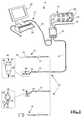
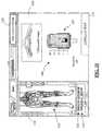
- FIG. 1is a perspective view of an exemplary surgical system 10 capable of nerve testing during anterior surgery (including disc space preparation, nerve stretching and/or nerve compression);
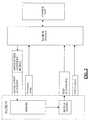
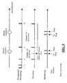
- FIG. 2is a block diagram of the surgical system 10 shown in FIG. 1 ;
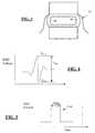
- FIG. 3is a front view of a prepared disc space including a remaining portion of annulus that acts as insulation to adjacent exiting nerve root;
- FIG. 4is a graph illustrating a plot of the neuromuscular response (EMG) of a given myotome over time based on a current stimulation pulse (similar to that shown in FIG. 5 ) applied to a nerve bundle coupled to the given myotome;
- EMGneuromuscular response
- FIG. 5is a graph illustrating a plot of a stimulation current pulse capable of producing a neuromuscular response (EMG) of the type shown in FIG. 4 ;
- FIG. 6is an illustration (graphical and schematic) of a method of automatically determining the maximum frequency (F Max ) of the stimulation current pulses according to one embodiment of the present invention
- FIG. 7is a graph illustrating a plot of peak-to-peak voltage (Vpp) for each given stimulation current level (I Stim ) forming a stimulation current pulse train according to the present invention (otherwise known as a “recruitment curve”);
- FIG. 8A-8Dare graphs illustrating a rapid current threshold-hunting algorithm according to one embodiment of the present invention.
- FIG. 9is a series of graphs illustrating a multi-channel rapid current threshold-hunting algorithm according to one embodiment of the present invention.
- FIG. 10is an is an illustration of an insulated tool capable of performing dynamic (real time) nerve testing when connected to the system 10 ;
- FIG. 11is an exemplary screen display of one embodiment of the annulus test function performed by the system 10 ;
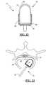
- FIG. 12is a perspective view of an exemplary disc space probe for use with the present invention.
- FIG. 13is a top view of the probe member of the disc space probe of FIG. 12 ;
- FIG. 14is a top cross-sectional view of a prepared disc space with the disc space probe of FIG. 12 inserted;
- FIGS. 15-16are exemplary views of pins used in the disc space probe
- FIG. 17illustrates an alternate embodiment of the pins used in the disc space probe
- FIG. 18is a top view of the probe member of FIG. 12 with an electrical connector for communicating with the control unit attached;
- FIG. 19is a perspective view of the electrical connector of FIG. 18 ;
- FIG. 20an exemplary screen display of another embodiment of the annulus test function performed by the system 10 ;
- FIG. 21an exemplary screen display of yet another embodiment of the annulus test function performed by the system 10 ;
- FIG. 22is a top view of a second embodiment of the disc space probe of FIG. 12 where the distal end is rounded;
- FIG. 23is a top view of the disc space probe of FIG. 21 inserted in a prepared disc space
- FIG. 24is a top view of a third embodiment of the disc space probe of FIG. 12 where the distal end has a generally sloped edge;
- FIG. 25is a top view of the disc space probe of FIG. 23 inserted in a prepared disc space
- FIG. 26A-26Care top views of a forth embodiment of the disc space prove of FIG. 17 where the probe has modular removable sections;
- FIGS. 27A-27Bare top down views of the disc space probe of FIGS. 26A-26D inserted in a prepared disc space;
- FIG. 28illustrates a disc space probe equipped with a tracking element for use with a position tracking system to monitor the position of the probe within the disc space;
- FIG. 29is an exemplary screen display of another embodiment of the annulus test function wherein the position of the disc space probe within the disc space is shown together with the stimulation results generated by the system 10 ;
- FIG. 30is an exemplary screen display of another embodiment of the annulus test function wherein the position of the annulus test probe within the disc space is shown together with the stimulation results generated by the system 10 ;
- FIG. 31is an exemplary screen display of another embodiment of the annulus test function wherein an ultrasound image obtained by an annulus test probe or a disc space probe is displayed together with the stimulation results generated by the system 10 .
- a portion of the discmust be excised from the disc space to make room for the particular implant (e.g. total disc replacement, nucleus replacement, fusion implant). It is generally advantageous to excise as much of a disc as possible, leaving only a thin outer layer of annulus to insulate the adjacent spinal cord and nerves. Breaching or removing too much of the annulus, however, may have unintended consequences, such as allowing inadvertent contact between a disc space preparation tool and/or intradiscal implant and the spinal cord or exiting nerve root. Such contact may potentially result in nerve damage and/or pain for the patient. It is also common during anterior spinal procedures to distract adjacent vertebral bodies in order to access the disc space or restore proper disc height. However, improper (i.e.
- the present inventionis directed at nerve testing during anterior surgery, including but not limited to total disc replacement, nucleus replacement, and interbody fusion surgeries.
- the inventionprovides information to help surgeons assess disc space preparation, including but not necessarily limited to, the adequacy of disc removal and the integrity of the remaining annulus, in combination with providing information to help prevent nerve damage during distraction and/or compression of vertebral bodies.
- FIG. 1illustrates, by way of example only, a surgical system 10 capable of carrying out these functions.
- the surgical system 10includes a control unit 12 , a patient module 14 , an EMG harness 16 and return electrode 20 coupled to the patient module 14 , and surgical accessories 24 capable of being coupled to the patient module 14 via one or more accessory cables 26 .
- the surgical accessories 24may include, but are not necessarily limited to, an annulus test probe 32 , a disc space probe 70 , a plunger-style electrical coupling device 47 , and a clip style coupling device 57 .
- the control unit 12includes a touch screen display 28 and a base 26 , which collectively contain the essential processing capabilities for controlling the surgical system 10 .
- the touch screen display 28is preferably equipped with a graphical user interface (GUI) capable of communicating information to the user and receiving instructions from the user.
- GUIgraphical user interface
- the base 26contains computer hardware and software that commands the stimulation sources, receives digitized signals and other information from the patient module 14 , processes the EMG responses, and displays the processed data to the operator via the display 28 .
- the primary functions of the software within the control unit 12include receiving user commands via the touch screen display 28 , activating stimulation, processing signal data according to defined algorithms (described below), displaying received parameters and processed data, and monitoring system status.
- the patient module 14is connected via a data cable 30 to the control unit 12 , and contains the electrical connections to all electrodes, signal conditioning circuitry, stimulator drive and steering circuitry, and a digital communications interface to the control unit 12 .
- the control unit 12is situated outside but close to the surgical field (such as on a cart adjacent the operating table) such that the display 28 is directed towards the surgeon for easy visualization.
- the patient module 14should be located between the patient's legs, or may be affixed to the end of the operating table at mid-leg level using a bedrail clamp. The position selected should be such that all EMG electrodes can reach their farthest desired location without tension during the surgical procedure.
- the surgical system 10conducts nerve testing by electrically stimulating spinal nerves and/or exiting nerve roots lying adjacent to the disc space via one or more stimulation electrodes located on the surgical accessories 24 , while monitoring the EMG responses of the muscle groups (myotomes) innervated by the nerves.
- the evoked responsesare then analyzed in relation to the stimulation signal to provide an indication of annular thickness for the given stimulation area. This is best shown in FIG. 4-5 , wherein FIG. 4 Illustrates the EMG response of a monitored myotome to the stimulation current pulse shown in FIG. 5 .
- the stimulation currentmay be coupled in any suitable fashion (i.e.
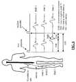
- EMG monitoringmay preferably be accomplished by connecting the EMG harness 16 to the myotomes corresponding to the exiting nerve roots associated with the particular spinal operation level. In a preferred embodiment, this is accomplished via 8 pairs of EMG electrodes 18 placed on the skin over the major muscle groups on the legs (four per side), an anode electrode 20 providing a return path for the stimulation current, and a common electrode 22 providing a ground reference to pre-amplifiers in the patient module 14 .
- EMG electrodes 18may be undertaken according to the manner shown in Table 1 below for spinal surgery:
- the frequency of the current pulsesis set at a suitable level such as, in a preferred embodiment, 4 Hz to 10 Hz (and most preferably 4.5 Hz), so as to prevent stimulating the nerve before it has a chance to recover from depolarization.
- FIG. 6illustrates an alternate manner of setting the maximum stimulation frequency (F max ), to the extent it is desired to do so rather than simply selecting a fixed maximum stimulation frequency (such as 4.5 Hz) as described above.
- F maxthe maximum frequency of the stimulation pulses is automatically adjusted.
- the Safety Marginis 5 ms, although it is contemplated that this could be varied according to any number of suitable durations.
- the stimulationswill be performed at intervals of 100-120 ms during the bracketing state, intervals of 200-240 ms during the bisection state, and intervals of 400-480 ms during the monitoring state (bracketing, bisection and monitoring states are discussed in detail below).
- the stimulationswill be performed at the fastest interval practical (but no faster than F max ) during the bracketing state, the fastest interval practical (but no faster than F max /2) during the bisection state, and the fastest interval practical (but no faster than F max /4) during the monitoring state.
- the maximum frequency used until F max is calculatedis preferably 10 Hz, although slower stimulation frequencies may be used during some acquisition algorithms.
- F maxused is periodically updated to ensure that it is still appropriate. For physiological reasons, the maximum frequency for stimulation will be set on a per-patient basis. Readings will be taken from all myotomes and the one with the slowest frequency (highest T 2 ) will be recorded.
- a basic premise behind the neurophysiology employed for the nerve testing (annulus test) in the present inventionis that each nerve has a characteristic threshold current level (I Thresh ) at which it will depolarize. Below this threshold, current stimulation will not evoke a significant neuromuscular response. Once the stimulation threshold (I Thresh ) is reached, the evoked response is reproducible and increases with increasing stimulation until saturation is reached as shown in FIG. 7 . This is known as a “recruitment curve.” In one embodiment, a significant EMG response is defined to have a V pp of approximately 100 uV. The lowest stimulation current that evokes this threshold voltage (V Thresh ) is called I Thresh .
- I threshdecreases as the degree of electrical communication between a stimulation impulse and a nerve increases (e.g. as the insulating annulus gets thinner and/or gets breached).
- monitoring I threshcan provide the surgeon with useful information such as the relative thickness of the remaining annulus in a prepared disc space or the integrity of the remaining annulus.
- V pppeak-to-peak voltage
- I Stimstimulation current
- the surgical system 10 of the present inventionmay employ any number of suitable artifact rejection techniques such as those shown and described in full in the above referenced co-pending and commonly assigned PCT App. Ser. No. PCT/US2004/025550, entitled “System and Methods for Performing Dynamic Pedicle Integrity Assessments,” filed on Aug. 5, 2004.
- the V pp informationis analyzed relative to the stimulation current in order to determine a relationship between the nerve and the given stimulation element transmitting the stimulation current. More specifically, the present invention determines these relationships (between nerve and the stimulation element) by identifying the minimum stimulation current (I Thresh ) capable of resulting in a predetermined V pp EMG response. According to the present invention, the determination of I Thresh , may be accomplished via any of a variety of suitable algorithms or techniques.
- FIGS. 8A-8Dillustrate, by way of example only, a threshold-hunting algorithm that employs a series of monopolar electrical stimulations to determine the stimulation current threshold I thresh for each EMG channel in range.
- the nerveis stimulated using current pulses with amplitude of I stim .
- the muscle groupsrespond with an evoked potential that has a peak-to-peak voltage of V pp .
- the object of this algorithmis to quickly find I Thresh , which once again, is the minimum I Stim that results in a V pp that is greater than a known threshold voltage V thresh .
- the value of I stimis adjusted by a bracketing method as follows.
- the initial bracket sizemay be, by way of example only, 11.0 mA and 2.0 mA. If the V pp corresponding to both of these stimulation currents is lower than V thresh , then the bracket size is doubled to 2.0 mA and 4.0 mA. This exponential doubling of the bracket size continues until the upper end of the bracket results in a V pp that is above V thresh . The size of the brackets is then reduced by a bisection method. A current stimulation value at the midpoint of the bracket is used and if this results in a V pp that is above V thresh , then the lower half becomes the new bracket. Likewise, if the midpoint V pp is below V thresh then the upper half becomes the new bracket. This bisection method is used until the bracket size has been reduced to I thresh mA. I Thresh is the value of I stim that is the higher end of the bracket.
- the threshold huntingwill support three states: bracketing, bisection, and monitoring.
- a stimulation current bracketis a range of stimulation currents that bracket the stimulation current threshold I Thresh .
- the upper and/or lower boundaries of a bracketmay be indeterminate.
- the width of a bracketis the upper boundary value minus the lower boundary value. If the stimulation current threshold I Thresh of a channel exceeds the maximum stimulation current, that threshold is considered out-of-range.
- threshold huntingwill employ the method below to select stimulation currents and identify stimulation current brackets for each EMG channel in range.
- the method for finding the minimum stimulation currentuses the methods of bracketing and bisection.
- the “root”is identified for a function that has the value ⁇ 1 for stimulation currents that do not evoke adequate response; the function has the value +1 for stimulation currents that evoke a response.
- the rootoccurs when the function jumps from ⁇ 1 to +1 as stimulation current is increased: the function never has the value of precisely zero.
- the rootwill not be known precisely, but only with some level of accuracy.
- the rootis found by identifying a range that must contain the root. The upper bound of this range is the lowest stimulation current I Thresh where the function returns the value +1 (i.e. the minimum stimulation current that evokes response).
- the annulus test functionbegins by adjusting the stimulation current from on the surgical instrument until the root is bracketed (e.g. “first bracket” in FIG. 8B ).
- the initial bracketing rangemay be provided in any number of suitable ranges. In one embodiment, the initial bracketing range is 1.0 to 2.0 mA. If the upper stimulation current does not evoke a response, the upper end of the range should be increased.
- the range scale factoris 2.
- the stimulation currentis preferably never increased by more than 10 mA in one iteration. The stimulation current should never exceed the programmed maximum stimulation current. For each stimulation, the algorithm will examine the response of each active channel to determine whether it falls within that bracket. Once the stimulation current threshold of each channel has been bracketed, the algorithm transitions to the bisection state.
- threshold huntingwill employ the method described below to select stimulation currents and narrow the bracket to a width of 0.1 mA for each channel with an in-range threshold.
- the range containing the rootis refined until the root is known with a specified accuracy.
- the bisection methodis used to refine the range containing the root. In one embodiment, the root should be found to a precision of 0.1 mA.
- the stimulation current at the midpoint of the bracketis used. If the stimulation evokes a response, the bracket shrinks to the lower half of the previous range. If the stimulation fails to evoke a response, the bracket shrinks to the upper half of the previous range.
- the algorithmis locked on the electrode position when the response threshold is bracketed by stimulation currents separated by 0.1 mA. The process is repeated for each of the active channels until all thresholds are precisely known. At that time, the algorithm enters the monitoring state.
- threshold huntingwill employ the method described below to select stimulation currents and identify whether stimulation current thresholds are changing.
- the stimulation current levelis decremented or incremented by 0.1 mA, depending on the response of a specific channel. If the threshold has not changed then the lower end of the bracket should not evoke a response, while the upper end of the bracket should. If either of these conditions fail, the bracket is adjusted accordingly. The process is repeated for each of the active channels to continue to assure that each threshold is bracketed. If stimulations fail to evoke the expected response three times in a row, then the algorithm transitions back to the bracketing state in order to reestablish the bracket.
- the algorithmWhen it is necessary to determine the stimulation current thresholds (I thresh ) for more than one channel, they will be obtained by time-multiplexing the threshold-hunting algorithm as shown in FIG. 9 .
- the algorithmwill start with a stimulation current bracket of 11.0 mA and increase the size of the bracket exponentially. With each bracket, the algorithm will measure the V pp of all channels to determine which bracket they fall into. After this first pass, the algorithm will know which exponential bracket contains the I thresh for each channel.
- the algorithmwill start with the lowest exponential bracket that contains an I thresh and bisect it until I thresh is found to within 0.1 mA.
- the algorithmwill monitor the upper and lower boundaries of the brackets for each I thresh , starting with the lowest. If the I thresh for one or more channels is not found in its bracket, then the algorithm goes back to the bracketing state to re-establish the bracket for those channels.
- the information displayed to the user on the display 28may include, but is not necessarily limited to, alpha-numeric and/or graphical information regarding, myotome/EMG levels, stimulation levels, threshold results (I thresh ), user instructions, and the instrument in use.
- the displayincludes the following components as set forth in Table 2:
- TABLE 2 Screen Component DescriptionSpine Image 104 An image of the human body/skeleton showing the electrode placement on or within the body, with labeled channel number tabs on each side (1-4 on the left and right). Left and right labels will show the patient orientation. The Channel number tabs 118 may be highlighted or colored depending on the specific function being performed and the specific electrodes in use.
- Display Area 106Shows procedure-specific information including stimulation results 108 Myotome 110 & A label to indicate the Myotome name and Nerve 112 names corresponding Nerve(s) associated with the channel of interest.
- Color IndicationEnhances stimulation results with a color display of green, yellow, or red corresponding to the relative safety level determined by the system.
- Function Graphics and/or nameto indicate the currently Indicator 114 active function (e.g. Annulus Test).
- Graphics and/or namemay also be displayed to indicate the instrument in use 120, such as the annulus test probe or disc space probe Stimulation Bar 116
- a graphical stimulation indicator depicting the present stimulation status (i.e.. on or off and stimulation current level) EMG waveforms EMG waveformsmay be optionally displayed on screen along with the stimulation results.
- stimulation signalsare delivered via one or more of the surgical accessories 24 , such as, by way of example only, annulus test probe 32 .
- the annulus test probe 32includes a handle 34 and a probe member 36 having a generally ball-tipped end 38 .
- the handle 34may be equipped with one or more buttons for selectively applying the electrical stimulation to the ball-tipped end 38 at the end of the probe member 36 .
- the ball tip 38 of the annulus test probe 32is placed in contact with the area of interest on the remaining annulus prior to insertion of an intradiscal implant or on the disc implant after insertion.
- the remaining annulus 40will prevent and/or impede the stimulation current (up to a certain amplitude) from communicating with the spinal nerves (not shown) and exiting nerve roots 42 .
- the amount of current amplitude required to communicate with the nerve 42is at least in part a function of the thickness of the remaining annulus 40 at the stimulation site (e.g. the thicker the annulus is, the higher the current must be to stimulate the nerve).
- monitoring I threshmay provide valuable information to the surgeon regarding the adequacy of the disc space preparation.
- the stimulation current required to stimulate the adjacent nerveis high it may indicate that not enough of the disc has been excised in that area.
- the ball tipped-end 38is preferably swept across the posterior aspect (and adjacent lateral sides if desired) of the annulus, or any portion thereof, while dynamically (continuously in real time) detecting I thresh . In this way, the thickness of the annulus may be assessed across the entire area of interest and any additional disc preparation may be selectively applied directly to areas in which the annulus remains thick, while thinner areas may be avoided.
- the probe member 36 and the ball-tipped end 88 of the annulus probe 32may be replaced with an electric coupling device.
- the electric coupling deviceis utilized to couple a disc space preparation tool, such as for example, a curette 66 ( FIG. 10 ) or pituitary (not shown), to the surgical system 10 .
- preparation toolsmay be configured to include an electrode region 68 , for emitting a stimulation signal, and a coupling region 70 for attaching one of the electric coupling devices 47 .
- the remainder of the toolis preferably insulated to ensure the stimulation signal only exits the tool at the electrode region 68 .
- a stimulation signalmay be passed through the surgical tool and annulus testing can be performed while the tool is in use.
- dynamic testingmay be performed during disc space preparation by coupling the surgical tool (e.g. curette or pituitary) to the surgical system 10 .
- annulus testingmay be performed during introduction of the implant.
- the electric coupling devicemay comprise a number of possible embodiments which permit the device to attach and hold a surgical tool while allowing transmission of a stimulation signal to the tool.
- One such electric coupling device 46utilizes a spring-loaded plunger to hold the surgical tool and transmit the stimulation signal.
- the plunger 48is composed of a conductive material such as metal.
- a nonconductive housing 50partially encases the rod 48 about its center. Extending from the housing 50 is an end plate 52 .
- An electrical cable 54connects the electric coupling device 46 to the handle 34 .
- a spring(not shown) is disposed within the housing 50 such that in a natural or “closed” state the plunger 48 is situated in close proximity to the endplate 52 .
- Exerting a compressive force on the springcauses a gap between the end plate 52 and the plunger 48 to widen to an “open” position, thereby allowing insertion of a surgical tool between the end plate 52 and plunger 48 .
- Releasing the cable 54allows the spring to return to a “closed” position, causing the plunger 48 to move laterally back towards the endplate such that a force is exerted upon the surgical tool and thereby holds it in place between the endplate 52 and the plunger 48 .
- the electrical stimulusmay be passed from the handle 34 through the cable 54 and plunger 48 to the surgical tool.
- the electrical coupling devicemay be embodied in the form of a clip 56 .
- the clip 56is comprised of two prongs hingedly coupled at a coupling point 58 such that the clip 56 includes an attachment end 60 and a non-attachment end 62 .
- a stimulation electrode 64is disposed on the attachment end 60 and communicates with an electric cable 54 extending from the non-attachment end 62 to the handle 34 .
- the prong ends at the attachment end 60touch. Depressing the prongs at the non-attachment end 62 in a direction towards each other causes a gap to form between the prong ends at the attachment end 60 .
- FIG. 11depicts an exemplary screen display of the Annulus Test function using the annulus test probe 32 .
- a function indicator tab 114indicates that system 10 is set to perform the annulus test and an instrument tab 120 indicates that the annulus test probe 32 is the active instrument.
- a stimulation bar 116provides a graphical representation of the stimulation current. Upon pressing the button on the stimulation handle 34 , the system 10 determines I thresh for each channel in range. The EMG channel possessing the lowest stimulation result 108 may be automatically highlighted and/or colored to clearly indicate this fact to the user. Additionally, EMG channel tabs 118 may be selected via the touch screen display 28 to show the result 108 of the corresponding nerves.
- An image of the human body/skeleton 104shows the electrode placement on or within the body and preferably highlights the electrodes associated with a selected channel.
- the system 10continuously monitors I thresh , and the stimulation results 108 shown in the display area 106 are updated after each threshold determination to reflect the lowest threshold detected.
- the stimulation resultsmay be displayed to the surgeon in conjunction with a color code including colors red, yellow, and green. Red, yellow, and green are preferably displayed to indicate to the surgeon the level of safety determined by the system 10 , wherein green represents a safe level, red an unsafe level, and yellow represents a level in-between the safe and unsafe levels.
- the surgical accessories 24may further include a disc space probe 74 that may be used in place of, or, in conjunction with annulus test probe 32 .
- the disc space probe 74comprises a probe member 76 and a handle 78 .
- Handle 78may comprise any instrument suitable for inserting the probe member 76 through an operating corridor into a prepared disc space 44 .
- Probe member 76includes a nonconductive housing 80 , having a distal end 82 and a proximal end 84 , and at least two conductive pins 86 extending therethrough.
- eight pins 86composed of a conductive material, such as (for example) metal, extend lengthwise through the interior of the housing 80 protruding for from both distal 82 and proximal 84 ends.
- Distal end 82is depicted in FIGS. 12-13 as being fashioned with a generally preferred convex curve which may reduce the risk damaging the annulus or adjacent tissue through inadvertent contact, however, it will be appreciated that distal end 82 may also include a generally concave, or generally flat surface as well.
- the heads 88 of pins 86are generally spherical or rounded, as best viewed in FIGS. 15-16 , so as not to damage tissue while entering the disc space or engaging the annulus.
- pins 86may have an enlarged, generally circular head 88 with a generally “T-shaped” shaped cross section, as best illustrated in FIG. 17 .
- the “T-shaped” pinheads 88equally distribute force among the several pins 86 , reducing any potential for puncturing the annulus fibrosis.
- the “T-shaped” heads 88may reduce any potential for the pins to get stuck in small fissures present within the annulus.
- the heads 88 of pins 86may individually compress in a proximal direction, thus ensuring that each pin 86 may make contact with the annulus despite the different surface curvatures of the disc space and/or any difference in thickness along portions of the annulus.
- Pin 86includes a proximal socket end 90 , a distal end 92 ending as head 88 , and a spring 94 .
- Spring 94is contained within socket end 90 and the distal end 92 is inserted into socket end 90 above spring 94 . In this manner, when a pin head 88 engages disc tissue before other heads 88 , the distal end 92 may compress into the socket end 90 as probe member 74 advances further into the disc space 44 , as illustrated in FIG. 14 .
- Probe member 76is dimensioned such that it may be positioned within a prepared disc space 44 .
- distal end 82 of probe member 76is preferably dimensioned such that it engages a substantial portion of the posterior aspect of the annulus, as best viewed in FIG. 14 . This allows the position of probe 74 within the disc space 44 to be approximated with relative accuracy and the I thresh determined for each pin 86 may be associated and displayed with respect to a particular site or region of the annulus.
- probe member 76may have a length at its center of approximately 37 mm, a width of approximately 27.5 mm, and a thickness of approximately 9 mm.
- probe member 76may have smaller dimensions, allowing distal end 82 to mate with different surface curvatures of the disc space 44 , as best demonstrated in FIGS. 14 , 22 , 24 .
- the I thresh resultsmay be displayed relative to their position on probe member 76 rather than their position on the annulus and/or various methods (described below) may be employed allowing the system 10 to determine the position of the probe within the annulus.
- disc space probe 74is inserted into a prepared disc space 44 , such as that illustrated in FIGS. 3 and 14 .
- Distal end 82is positioned within the disc space such that the heads 88 of pins 86 engage the remaining annulus 40 , which again serves to insulate the adjacent spinal nerves and exiting nerve roots 42 from inadvertent contact with a surgical tool or implant.
- Stimulation impulsesare applied one at a time to each pin 86 and the stimulation threshold, I thresh , required to evoke a significant EMG response from the muscles innervated by the adjacent nerves is calculated for each pin 86 .
- the individual stimulation thresholds determinedprovide an indication of annular thickness at each pin position. Using this information, the surgeon may selectively excise more tissue from thicker areas of the annulus and avoid excising additional tissue from thinner areas. The surgeon is thereby able to achieve the advantageous result of removing more annular tissue without increasing the risk to adjacent nerves.
- stimulation impulsesmay be applied manually to each pin 86 , one by one.
- annulus test probe 32may be used to apply a stimulation signal to each pin 86 (as depicted in FIG. 14 ).
- the ball tipped end 38 of annulus test probe 32may engage the proximal end 90 of pins 86 .
- the proximal end 90 of pins 86may be generally convex or cup shaped such that it may easily receive the ball tipped end 38 .
- a button on the annulus test probe handle 34may be pressed initiating a series of stimulation signals by which the stimulation threshold, I thresh , may be determined.
- the surgical system 10may automatically apply stimulation to each pin 86 , one by one.
- a female connecter 96provided with socket holes 100 for engaging the tail end of all pins 86 .
- Connector 96is communicatively linked to the surgical system 10 via cable 98 .
- connector 96is attached to handle 34 , replacing probe member 36 and ball tipped end 38 .
- the system 10Upon pressing the button on handle 34 , the system 10 automatically delivers a series of stimulation impulses one at a time to each pin 86 until the stimulation threshold is found for each in turn.
- pressing the button on handle 34may stimulate only one pin 86 .
- the system 10automatically switches to the next pin 86 in sequence and pressing the button on handle 34 again will initiates the threshold determination for that pin 86 .
- FIGS. 20-21are exemplary screen displays, set forth by way of example only, of alternate embodiments of the annulus test function.
- FIG. 20represents a preferred embodiment of the annulus test function when the position of the probe member 76 within the disc space is known by the system 10 , such as for example only, when the dimensions of the probe member 76 are substantially similar to the dimensions of the disc.
- FIG. 21represents a preferred embodiment of the annulus test function when the position of the probe member 76 within the disc space is not known by the system 10 , such as for example only, when the dimensions of the probe member 76 are substantially dissimilar to the dimensions of the disc.
- a function indicator tab 114indicates that system 10 is set to perform the annulus test and an instrument tab 120 indicates that the disc space probe 76 is the active instrument.
- a stimulation bar 116provides a graphical representation of the stimulation current. Upon pressing the button on the stimulation handle 34 the system 10 determines I thresh for each channel in range, for each pin 86 in sequence. EMG channel tabs 118 may be selected via the touch screen display 28 to view a specific stimulation result 108 . The lowest stimulation threshold determined for each pin 86 is shown in the display area 106 so that the results may be compared to one another and against predetermined parameters.
- FIG. 20includes a 2-dimensional model 122 of a disc space positioned in the display area 106 .
- Stimulation results 108 for each pin 86are displayed within the model to relate each stimulation threshold to a site or region on the actual annulus.
- stimulation results 108are displayed as a bar graph 124 and preferably the bar graph is arranged on an enlarged image of the probe member 76 such that each bar on the graph may be visually correlated to a specific pin 86 on the probe member 76 .
- the stimulation resultsmay be displayed to the surgeon in conjunction with a color indicator including the colors red, yellow, and green.
- Red, yellow, and greenare preferably displayed to indicate to the surgeon the level of safety determined by the system 10 , wherein green represents a safe level, red represents an unsafe level, and yellow represents a level in-between the safe and unsafe levels.
- a green displaycorresponds to a stimulation threshold range of 10 mA or greater
- a yellow displaydenotes a stimulation threshold range of 5-9 mA
- a red displaydenotes a stimulation threshold range of 4 mA or below.
- FIG. 22illustrates an example of an alternate embodiment of the present invention.
- Distal end 82has a generally rounded shape that contours to the shape of the posteriolateral portion of the annulus which may be desirable when an anteriolateral approach is used as illustrated in FIG. 23 .
- FIG. 24illustrates still another embodiment of the present invention.
- Distal end 82has a generally half rounded shape, maintaining the original convex curve shown in FIG. 13 from one edge to the approximate center and steeply sloping toward the other edge. This shape allows disc test probe 74 to accommodate a more pronounced anteriolateral approach such as that as illustrated in FIG. 25 .
- probe member 74is shown with the distal end 82 sloped in only one direction, it will be appreciated that distal end 82 may be sloped in either direction to accommodate an anteriolateral approach from either side of the body.
- FIG. 26A-26Cillustrate yet one more embodiment of the present invention.
- the probe member 76 of the test probe 74is comprised of modular sections 102 such that one or more sections 102 may be selectively removed depending on the specific needs and requirements of the procedure.
- This embodimentincorporates all the advantages of the above-described embodiments into a single probe. Removing one or more modular sections 102 decreases the width of the probe 74 allowing the probe to maneuver through small openings and to accommodate different surface curvatures.
- FIG. 26Ashows the modular probe member 76 with no sections 102 removed.
- FIG. 26Bshows the probe member 76 after a section 102 has been removed from one side
- FIG. 26Cshows the probe member after a section 102 has been removed from the center. Although probe member 76 is shown in FIG.
- FIG. 27A-27Billustrates the probe 74 of FIG. 26A-26C in use with the disc space 44 .
- any of the various exemplary embodiments of disc space probe 74 and annulus test probe 32 described abovemay optionally be equipped with tracking elements 126 comprising part of a position tracking system (PTS) operatively linked to the surgical system 10 .
- the PTSmay be used to track the position and orientation of the probes 74 , 32 while in use within the body.
- PTSsare believed to be well known in the prior art and will thus be described only briefly below.
- a variety of different PTSsmay be suitable for use with the surgical system 10 .
- the PTSmay be a magnetic tracking system, such as, for the purposes of example only, the miniBIRDTM and microBIRDTM systems offered commercially by Ascension Technology Corporation (Burlington, Vt.).
- the tracking element 126 in the magnetic tracking systemmay be a magnetic field sensor that detects and measures magnetic fields emitted by a nearby transmitter fixed in a known position.
- the tracking element 126may be a small transmitter that generates a magnetic field, which is detected and measured by a magnetic field sensor fixed in a known position.
- the tracking elementis preferably attached to or integrated in the probe member 76 of disc space probe 74 , or, near the ball-tipped end of annulus test probe 32 , as depicted in FIG. 28 .
- the position and orientation of the tracking element 126may be continuously determined relative to the known fixed position of the transmitter or sensor and thus the position of the probes 70 , 32 may also be determined.
- the magnetic tracking systemmay be configured to automatically disable magnetic field transmission just prior to initiation of a stimulation signal for annulus testing in order to avoid interference between the systems. Magnetic field transmission preferably resumes automatically upon cessation of the stimulation signal.
- the PTSmay be an optical tracking system, such as, by way of example only, the OPTOTRACK® and POLARIS® systems offered by Northern Digital Inc. (Ontario, Canada).
- the tracing elements 126may include one or more light emitting beacons, such as by way of example only, light-emitting diodes (LED), preferably positioned on the handle members 78 , 34 of probes 74 , 32 , respectively.
- the tracking elements 126may include one or more light reflecting beacons that may be detected when illuminated with a light source, such as, for example infrared light.
- a set of optical sensors or cameras, positioned near the surgical fieldmay be utilized to determine the position and orientation of the tracking elements 126 and thus the position and orientation of the probes 70 , 32 may also be determined.
- Other PTSssuch as for example, global positioning systems and ultrasound tracking systems may also be used.
- Use of a PTS with the surgical system 10may further enhance the stimulation threshold information generated by providing positional information to closely relate each I thresh value to a specific site or region within the disc space. This may be accomplished by applying known methods to combine the positional data obtained from tracking element 126 and a disc space image displayed on the GUI 28 .
- the external imageis a 2-dimensional model showing a transverse cross-sectional view of a disc space and adjacent cord and nerve structures.
- the 2-dimensional modelis calibrated to the actual patient disc space such that the position of probes 74 , 32 in the actual disc space 44 may be shown with accuracy in the 2-dimensional model.
- One method of calibrationmay be performed by tagging exposed or accessible portions of the annulus with at least one, and preferably more, reference markers that are visible to the applicable tracking system.
- Reference markersmay include, by way of example only, additional magnetic field sensors or LEDs depending on the tracking system in use.
- Corresponding sites on the 2-dimensional modelare then identified by user selection on the GUI display and an algorithm is used to register the “patient space” coordinates of the reference markers into the “image space” of the model. Subsequent movement of the tracking elements 126 is tracked relative to the reference markers and the position of probes 74 , 32 may thus be shown with accuracy on the 2-dimensional model.
- the 2-dimensional model 122may be replaced by actual images of the patients spine obtained prior to or during the surgical procedure such as, such as for example images acquired by MRI, CT, fluoroscopy, among other known imaging techniques. Additional embodiments are contemplated wherein the position of the probes is registered and displayed relative to 3-dimensional images, such as for example, a 3-dimensional model image or 3-dimensional images of the patients own disc space which may be acquired preoperatively.
- FIG. 29illustrates an example of a screen display, set forth by way of example only, for the annulus test function utilizing a PTS to accurately determine the position of the probe within the disc space.
- a function indicator tab 114indicates that system 10 is set to perform the annulus test and an instrument tab 120 indicates that the probe in use.
- a stimulation bar 116provides a graphical representation of the stimulation current. The lowest stimulation threshold determined for each pin 86 is shown in the display area 106 .
- the display are 106includes a 2-dimensional model 122 of a disc space.
- the threshold results 108are displayed within the disc space model.
- the threshold resultsare displayed as a bar graph 124 and preferably the bar graph is arranged on an enlarged image of the probe member 76 such that each bar on the graph may be visually correlated to a specific pin 86 on the probe member 76 .
- the stimulation resultsare positioned to indicate the position of the probe within the disc space 44 as determined by the PTS.
- annulus test probe 32is in use the position of the probe 32 is indicated within the model and the threshold value is displayed separately, as illustrated by way of example only in FIG. 30 .
- Stimulation resultsare preferably displayed in conjunction with the color indicators as previously described.
- the surgical system 10may be optionally equipped to perform intraoperative ultrasound imaging of the annulus and other adjacent tissues.
- the system 10employs ultrasound equipment and techniques tailored for intraoperative use, which are considered well known in the art and will be described only briefly.
- At least one ultrasound transducer 128is preferably attached to or integrated near the distal end of the annulus test probe 32 or disc space probe 74 ( FIG. 28 ).
- a separate ultrasound probemay be advanced into the disc space alone, or, in conjunction with probes 74 or 32 .
- acoustic signals of a defined frequencyranging between 50 kHz and 16 MHz, are directed from the transducer towards the annular tissue.
- the ultrasound signalsreflect off tissue boundaries (such as the exterior surface of the annulus) and are received back at the transducer, or at a separate receiving transducer, and then transmitted to the control unit 12 to be converted into viewable images.
- the ultrasound imagesgraphically represent the annulus and specifically demonstrate the thickness of remaining annulus.
- the imagesare preferably shown on the GUI display 28 together with the stimulation threshold data generated by the system 10 .
- FIG. 31illustrates one embodiment of a screen display for the annulus test function when ultrasound imaging is utilized.
- the screenincludes the function indicator tab 114 , instrument tab 120 , stimulation bar 116 , channels tabs 118 , and spine image 104 described above.
- Stimulation threshold resultsare shown in the display area 106 according to any of the methods described above with reference to FIGS. 11 , 20 , 21 .
- the ultrasound imageis shown in the display area 106 together with the stimulation threshold results 108 .
- the annulusmay appear as a dark band in the ultrasound image.
- tissue boundariesmay be colorized to aid the surgeon in distinguishing the different tissues.
- Anterior surgeriesincluding but not limited to, anterior disc replacement surgery, nucleus replacement, and interbody fusion often require distraction of adjacent vertebral bodies in order to access the disc space and regain proper disc height, as well as compression to ensure the implant remains in the proper position and/or to restore spinal alignment after introduction of an implant.
- Distracting the vertebral bodiesmay stretch the nerves, while compression may result in pinching or compression of the exiting nerves, both of which can potentially result in nerve damage or pain.
- insertion of an incorrectly sized intradiscal implantsuch as by way of example only, a total disc replacement or interbody fusion cage, may again result in potentially stretching or compressing the exiting nerves and cause nerve damage or pain.
- a nervewhen a nerve is compressed or stretched, it will emit a burst or train of spontaneous nerve activity.
- the system 10may conduct free running EMG to capture this activity.
- Spontaneous EMG activitymay be displayed to the surgeon via the GUI display 28 .
- An audio pick-upmay also be provided as an optional feature according to the present invention. The audio pick-up is capable of transmitting sounds representative of such activity such that the surgeon can monitor this response on audio to help him determine if there has been stress to one of the nerves.
- the surgical system 10 and related methodshave been described above according to one embodiment of the present invention. It will be readily appreciated that various modifications may be undertaken, or certain steps or algorithms omitted or substituted, without departing from the scope of the present invention.
- the present inventionmay be implemented using any combination of computer programming software, firmware or hardware.
- the computer programming code(whether software or firmware) according to the invention will typically be stored in one or more machine readable storage mediums such as fixed (hard) drives, diskettes, optical disks, magnetic tape, semiconductor memories such as ROMs, PROMs, etc., thereby making an article of manufacture in accordance with the invention.
- the article of manufacture containing the computer programming codeis used by either executing the code directly from the storage device, by copying the code from the storage device into another storage device such as a hard disk, RAM, etc. or by transmitting the code on a network for remote execution.
- many different combinations of the abovemay be used and accordingly the present invention is not limited by the specified scope.
- the surgical system 10it will be appreciated as within the scope of the invention to perform nerve testing during anterior surgery, as described herein, with any number of different neurophysiology based testing, including but not limited to the “NIM SPINE” testing system offered by Medtronic Sofamor Danek, Inc.
Landscapes
- Health & Medical Sciences (AREA)
- Life Sciences & Earth Sciences (AREA)
- Surgery (AREA)
- Neurology (AREA)
- General Health & Medical Sciences (AREA)
- Veterinary Medicine (AREA)
- Engineering & Computer Science (AREA)
- Biomedical Technology (AREA)
- Heart & Thoracic Surgery (AREA)
- Medical Informatics (AREA)
- Molecular Biology (AREA)
- Animal Behavior & Ethology (AREA)
- Public Health (AREA)
- Pathology (AREA)
- Neurosurgery (AREA)
- Physics & Mathematics (AREA)
- Biophysics (AREA)
- Oral & Maxillofacial Surgery (AREA)
- Nuclear Medicine, Radiotherapy & Molecular Imaging (AREA)
- Physiology (AREA)
- Measurement And Recording Of Electrical Phenomena And Electrical Characteristics Of The Living Body (AREA)
- Eye Examination Apparatus (AREA)
Abstract
Description
| TABLE 1 | |||
| Color | Channel ID | Myotome | Spinal |
| Blue | Right | ||
| 1 | Right Vastus Medialis | L2, L3, | |
| Violet | Right | ||
| 2 | Right Tibialis Anterior | L4, | |
| Grey | Right | ||
| 3 | Right Biceps Femoris | L5, S1, | |
| White | Right | ||
| 4 | Right Gastroc. Medial | S1, | |
| Red | Left | ||
| 1 | Left Vastus Medialis | L2, L3, | |
| Orange | Left | ||
| 2 | Left Tibialis Anterior | L4, | |
| Yellow | Left | ||
| 3 | Left Biceps Femoris | L5, S1, | |
| Green | Left | ||
| 4 | Left Gastroc. Medial | S1, S2 | |
| TABLE 2 | |
| Screen Component | |
| Spine Image | |
| 104 | An image of the human body/skeleton showing the |
| electrode placement on or within the body, with | |
| labeled channel number tabs on each side (1-4 | |
| on the left and right). Left and right labels | |
| will show the patient orientation. The | |
| number tabs | |
| 118 may be highlighted or colored | |
| depending on the specific function being | |
| performed and the specific electrodes in use. | |
| Shows procedure-specific information including | |
| Myotome 110 & | A label to indicate the Myotome name and |
| corresponding Nerve(s) associated with the | |
| channel of interest. | |
| Color Indication | Enhances stimulation results with a color |
| display of green, yellow, or red corresponding | |
| to the relative safety level determined by | |
| the system. | |
| Function | Graphics and/or name to indicate the currently |
| active function (e.g. Annulus Test). In an | |
| alternate embodiment, Graphics and/or name may | |
| also be displayed to indicate the instrument | |
| in | |
| disc space probe | |
| Stimulation Bar 116 | A graphical stimulation indicator depicting |
| the present stimulation status (i.e.. on or | |
| off and stimulation current level) | |
| EMG waveforms | EMG waveforms may be optionally displayed |
| on screen along with the stimulation results. | |
Claims (17)
Priority Applications (1)
| Application Number | Priority Date | Filing Date | Title |
|---|---|---|---|
| US11/883,710US8568331B2 (en) | 2005-02-02 | 2006-02-02 | System and methods for monitoring during anterior surgery |
Applications Claiming Priority (3)
| Application Number | Priority Date | Filing Date | Title |
|---|---|---|---|
| US64973205P | 2005-02-02 | 2005-02-02 | |
| US11/883,710US8568331B2 (en) | 2005-02-02 | 2006-02-02 | System and methods for monitoring during anterior surgery |
| PCT/US2006/003967WO2006084194A2 (en) | 2005-02-02 | 2006-02-02 | System and methods for monitoring during anterior surgery |
Publications (2)
| Publication Number | Publication Date |
|---|---|
| US20090105604A1 US20090105604A1 (en) | 2009-04-23 |
| US8568331B2true US8568331B2 (en) | 2013-10-29 |
Family
ID=36777994
Family Applications (1)
| Application Number | Title | Priority Date | Filing Date |
|---|---|---|---|
| US11/883,710Active2029-12-23US8568331B2 (en) | 2005-02-02 | 2006-02-02 | System and methods for monitoring during anterior surgery |
Country Status (2)
| Country | Link |
|---|---|
| US (1) | US8568331B2 (en) |
| WO (1) | WO2006084194A2 (en) |
Cited By (13)
| Publication number | Priority date | Publication date | Assignee | Title |
|---|---|---|---|---|
| US20120089044A1 (en)* | 2010-10-08 | 2012-04-12 | Nihon Kohden Corporation | Biological signal display apparatus |
| US20160071270A1 (en)* | 2013-05-20 | 2016-03-10 | Kabushiki Kaisha Toshiba | Magnetic resonance imaging apparatus |
| US10016600B2 (en) | 2013-05-30 | 2018-07-10 | Neurostim Solutions, Llc | Topical neurological stimulation |
| US10953225B2 (en) | 2017-11-07 | 2021-03-23 | Neurostim Oab, Inc. | Non-invasive nerve activator with adaptive circuit |
| US11077301B2 (en) | 2015-02-21 | 2021-08-03 | NeurostimOAB, Inc. | Topical nerve stimulator and sensor for bladder control |
| US11229789B2 (en) | 2013-05-30 | 2022-01-25 | Neurostim Oab, Inc. | Neuro activator with controller |
| US11458311B2 (en) | 2019-06-26 | 2022-10-04 | Neurostim Technologies Llc | Non-invasive nerve activator patch with adaptive circuit |
| US11701047B2 (en) | 2017-06-16 | 2023-07-18 | Alphatec Spine, Inc. | Systems, methods, and devices for detecting the threshold of nerve-muscle response using variable frequency of stimulation |
| US11730958B2 (en) | 2019-12-16 | 2023-08-22 | Neurostim Solutions, Llc | Non-invasive nerve activator with boosted charge delivery |
| US11963775B2 (en) | 2017-03-22 | 2024-04-23 | Safeop Surgical, Inc. | Medical systems and methods for detecting changes in electrophysiological evoked potentials |
| US11963784B2 (en) | 2013-11-07 | 2024-04-23 | Safeop Surgical, Inc. | Systems and methods for detecting nerve function |
| US11986321B2 (en) | 2016-09-22 | 2024-05-21 | Safeop Surgical, Inc. | System and method for detecting and removing periodic non-physiological artifact from evoked potentials |
| US12048567B2 (en) | 2015-05-04 | 2024-07-30 | Safeop Surgical, Inc. | System, method, and computer algorithm for measuring, displaying, and accurately detecting changes in electrophysiological evoked potentials |
Families Citing this family (77)
| Publication number | Priority date | Publication date | Assignee | Title |
|---|---|---|---|---|
| US7959577B2 (en)* | 2007-09-06 | 2011-06-14 | Baxano, Inc. | Method, system, and apparatus for neural localization |
| US8062300B2 (en) | 2006-05-04 | 2011-11-22 | Baxano, Inc. | Tissue removal with at least partially flexible devices |
| US20110190772A1 (en) | 2004-10-15 | 2011-08-04 | Vahid Saadat | Powered tissue modification devices and methods |
| US8257356B2 (en) | 2004-10-15 | 2012-09-04 | Baxano, Inc. | Guidewire exchange systems to treat spinal stenosis |
| US20090171381A1 (en)* | 2007-12-28 | 2009-07-02 | Schmitz Gregory P | Devices, methods and systems for neural localization |
| US8221397B2 (en) | 2004-10-15 | 2012-07-17 | Baxano, Inc. | Devices and methods for tissue modification |
| US7578819B2 (en) | 2005-05-16 | 2009-08-25 | Baxano, Inc. | Spinal access and neural localization |
| US20080103504A1 (en)* | 2006-10-30 | 2008-05-01 | Schmitz Gregory P | Percutaneous spinal stenosis treatment |
| US9101386B2 (en) | 2004-10-15 | 2015-08-11 | Amendia, Inc. | Devices and methods for treating tissue |
| US20070213734A1 (en)* | 2006-03-13 | 2007-09-13 | Bleich Jeffery L | Tissue modification barrier devices and methods |
| US20100004654A1 (en)* | 2008-07-01 | 2010-01-07 | Schmitz Gregory P | Access and tissue modification systems and methods |
| US9247952B2 (en) | 2004-10-15 | 2016-02-02 | Amendia, Inc. | Devices and methods for tissue access |
| JP5243034B2 (en) | 2004-10-15 | 2013-07-24 | バクサノ,インク. | Tissue removal device |
| US7887538B2 (en)* | 2005-10-15 | 2011-02-15 | Baxano, Inc. | Methods and apparatus for tissue modification |
| US20100331883A1 (en) | 2004-10-15 | 2010-12-30 | Schmitz Gregory P | Access and tissue modification systems and methods |
| US7857813B2 (en) | 2006-08-29 | 2010-12-28 | Baxano, Inc. | Tissue access guidewire system and method |
| US7938830B2 (en) | 2004-10-15 | 2011-05-10 | Baxano, Inc. | Powered tissue modification devices and methods |
| US8048080B2 (en) | 2004-10-15 | 2011-11-01 | Baxano, Inc. | Flexible tissue rasp |
| US8430881B2 (en) | 2004-10-15 | 2013-04-30 | Baxano, Inc. | Mechanical tissue modification devices and methods |
| US8613745B2 (en) | 2004-10-15 | 2013-12-24 | Baxano Surgical, Inc. | Methods, systems and devices for carpal tunnel release |
| US8366712B2 (en) | 2005-10-15 | 2013-02-05 | Baxano, Inc. | Multiple pathways for spinal nerve root decompression from a single access point |
| US8092456B2 (en) | 2005-10-15 | 2012-01-10 | Baxano, Inc. | Multiple pathways for spinal nerve root decompression from a single access point |
| US8062298B2 (en) | 2005-10-15 | 2011-11-22 | Baxano, Inc. | Flexible tissue removal devices and methods |
| US7906239B2 (en)* | 2006-03-06 | 2011-03-15 | Sony Corporation | Cathode active material, method for producing the same, and nonaqueous electrolyte secondary battery |
| US20080183188A1 (en)* | 2007-01-25 | 2008-07-31 | Warsaw Orthopedic, Inc. | Integrated Surgical Navigational and Neuromonitoring System |
| US7987001B2 (en) | 2007-01-25 | 2011-07-26 | Warsaw Orthopedic, Inc. | Surgical navigational and neuromonitoring instrument |
| US20080183074A1 (en)* | 2007-01-25 | 2008-07-31 | Warsaw Orthopedic, Inc. | Method and apparatus for coordinated display of anatomical and neuromonitoring information |
| US8374673B2 (en) | 2007-01-25 | 2013-02-12 | Warsaw Orthopedic, Inc. | Integrated surgical navigational and neuromonitoring system having automated surgical assistance and control |
| US20080183068A1 (en)* | 2007-01-25 | 2008-07-31 | Warsaw Orthopedic, Inc. | Integrated Visualization of Surgical Navigational and Neural Monitoring Information |
| WO2008124079A1 (en)* | 2007-04-03 | 2008-10-16 | Nuvasive, Inc. | Neurophysiologic monitoring system |
| US8343079B2 (en)* | 2007-10-18 | 2013-01-01 | Innovative Surgical Solutions, Llc | Neural monitoring sensor |
| US8192436B2 (en) | 2007-12-07 | 2012-06-05 | Baxano, Inc. | Tissue modification devices |
| US9314253B2 (en) | 2008-07-01 | 2016-04-19 | Amendia, Inc. | Tissue modification devices and methods |
| US8398641B2 (en) | 2008-07-01 | 2013-03-19 | Baxano, Inc. | Tissue modification devices and methods |
| US8409206B2 (en) | 2008-07-01 | 2013-04-02 | Baxano, Inc. | Tissue modification devices and methods |
| AU2009271047B2 (en) | 2008-07-14 | 2014-04-17 | Baxano Surgical, Inc. | Tissue modification devices |
| US9084551B2 (en) | 2008-12-08 | 2015-07-21 | Medtronic Xomed, Inc. | Method and system for monitoring a nerve |
| EP2405823A4 (en) | 2009-03-13 | 2012-07-04 | Baxano Inc | Flexible neural localization devices and methods |
| US8394102B2 (en) | 2009-06-25 | 2013-03-12 | Baxano, Inc. | Surgical tools for treatment of spinal stenosis |
| US20110230785A1 (en)* | 2010-03-16 | 2011-09-22 | ProNerve, LLC | Somatosensory Evoked Potential (SSEP) Automated Alert System |
| WO2012029065A2 (en)* | 2010-09-05 | 2012-03-08 | Venus Concept Ltd | A self operated esthetic device with a substrate |
| US9392953B1 (en)* | 2010-09-17 | 2016-07-19 | Nuvasive, Inc. | Neurophysiologic monitoring |
| US20120101405A1 (en)* | 2010-10-21 | 2012-04-26 | Aalborg Universitet | Method for predicting cutaneous afferent nerve fiber excitation |
| US9155503B2 (en)* | 2010-10-27 | 2015-10-13 | Cadwell Labs | Apparatus, system, and method for mapping the location of a nerve |
| US11877860B2 (en) | 2012-11-06 | 2024-01-23 | Nuvasive, Inc. | Systems and methods for performing neurophysiologic monitoring during spine surgery |
| US11259737B2 (en) | 2012-11-06 | 2022-03-01 | Nuvasive, Inc. | Systems and methods for performing neurophysiologic monitoring during spine surgery |
| US9757067B1 (en) | 2012-11-09 | 2017-09-12 | Nuvasive, Inc. | Systems and methods for performing neurophysiologic monitoring during spine surgery |
| US9757072B1 (en) | 2013-02-11 | 2017-09-12 | Nuvasive, Inc. | Waveform marker placement algorithm for use in neurophysiologic monitoring |
| US10098585B2 (en) | 2013-03-15 | 2018-10-16 | Cadwell Laboratories, Inc. | Neuromonitoring systems and methods |
| US10561465B2 (en)* | 2013-10-09 | 2020-02-18 | Nuvasive, Inc. | Surgical spinal correction |
| US9848922B2 (en)* | 2013-10-09 | 2017-12-26 | Nuvasive, Inc. | Systems and methods for performing spine surgery |
| ITRN20130043A1 (en)* | 2013-10-09 | 2015-04-10 | Gilberto Pari | MEDICAL STATION FOR ELECTROSTIMULATION OF THE NERVOUS SYSTEM |
| US10022090B2 (en) | 2013-10-18 | 2018-07-17 | Atlantic Health System, Inc. | Nerve protecting dissection device |
| US11166672B2 (en) | 2013-10-18 | 2021-11-09 | Atlantic Health System, Inc. | Nerve protecting dissection device |
| US10709509B2 (en) | 2014-06-17 | 2020-07-14 | Nuvasive, Inc. | Systems and methods for planning, performing, and assessing spinal correction during surgery |
| AU2015301401B2 (en) | 2014-08-15 | 2020-01-16 | Axonics Modulation Technologies, Inc. | Electromyographic lead positioning and stimulation titration in a nerve stimulation system for treatment of overactive bladder |
| CA2958210C (en) | 2014-08-15 | 2023-09-26 | Axonics Modulation Technologies, Inc. | Integrated electromyographic clinician programmer for use with an implantable neurostimulator |
| ES2782556T3 (en) | 2014-08-15 | 2020-09-15 | Axonics Modulation Tech Inc | System for neurostimulation electrode configurations based on neuronal location |
| US10420480B1 (en) | 2014-09-16 | 2019-09-24 | Nuvasive, Inc. | Systems and methods for performing neurophysiologic monitoring |
| US10433793B1 (en) | 2015-03-27 | 2019-10-08 | Cadwell Laboratories, Inc. | Methods and systems for simultaneous review of brain activity and physical manifestations of users |
| US11241297B2 (en) | 2016-12-12 | 2022-02-08 | Cadwell Laboratories, Inc. | System and method for high density electrode management |
| US9935395B1 (en) | 2017-01-23 | 2018-04-03 | Cadwell Laboratories, Inc. | Mass connection plate for electrical connectors |
| CN107085671A (en)* | 2017-06-29 | 2017-08-22 | 江苏奥康尼医疗科技发展有限公司 | A kind of auxiliary equipment of repair of cartilage operation |
| US11517239B2 (en) | 2018-04-05 | 2022-12-06 | Cadwell Laboratories, Inc. | Systems and methods for processing and displaying electromyographic signals |
| US11596337B2 (en) | 2018-04-24 | 2023-03-07 | Cadwell Laboratories, Inc | Methods and systems for operating an intraoperative neurophysiological monitoring system in conjunction with electrocautery procedures |
| US11253182B2 (en) | 2018-05-04 | 2022-02-22 | Cadwell Laboratories, Inc. | Apparatus and method for polyphasic multi-output constant-current and constant-voltage neurophysiological stimulation |
| US11992339B2 (en) | 2018-05-04 | 2024-05-28 | Cadwell Laboratories, Inc. | Systems and methods for dynamic neurophysiological stimulation |
| US11443649B2 (en) | 2018-06-29 | 2022-09-13 | Cadwell Laboratories, Inc. | Neurophysiological monitoring training simulator |
| US11185684B2 (en) | 2018-09-18 | 2021-11-30 | Cadwell Laboratories, Inc. | Minimally invasive two-dimensional grid electrode |
| US11517245B2 (en) | 2018-10-30 | 2022-12-06 | Cadwell Laboratories, Inc. | Method and system for data synchronization |
| US11471087B2 (en) | 2018-11-09 | 2022-10-18 | Cadwell Laboratories, Inc. | Integrity verification system for testing high channel count neuromonitoring recording equipment |
| US11317841B2 (en) | 2018-11-14 | 2022-05-03 | Cadwell Laboratories, Inc. | Method and system for electrode verification |
| US11529107B2 (en) | 2018-11-27 | 2022-12-20 | Cadwell Laboratories, Inc. | Methods for automatic generation of EEG montages |
| US11128076B2 (en) | 2019-01-21 | 2021-09-21 | Cadwell Laboratories, Inc. | Connector receptacle |
| WO2020242900A1 (en) | 2019-05-24 | 2020-12-03 | Axonics Modulation Technologies, Inc. | Trainer device for a neurostimulator programmer and associated methods of use with a neurostimulation system |
| US11439829B2 (en) | 2019-05-24 | 2022-09-13 | Axonics, Inc. | Clinician programmer methods and systems for maintaining target operating temperatures |
| US11399777B2 (en)* | 2019-09-27 | 2022-08-02 | DePuy Synthes Products, Inc. | Intraoperative neural monitoring system and method |
Citations (184)
| Publication number | Priority date | Publication date | Assignee | Title |
|---|---|---|---|---|
| US972983A (en) | 1909-05-17 | 1910-10-18 | Lester R Lantz | Dilator. |
| US1328624A (en) | 1917-08-13 | 1920-01-20 | Frank B Graham | Dilator |
| US1548184A (en) | 1923-04-11 | 1925-08-04 | Will J Cameron | Holder and control for pulp testers |
| US2704064A (en) | 1952-09-10 | 1955-03-15 | Meditron Company | Neurosurgical stimulator |
| US2736002A (en) | 1956-02-21 | oriel | ||
| US2808826A (en) | 1956-01-19 | 1957-10-08 | Teca Corp | Electro-diagnostic apparatus and a circuit therefor |
| US3364929A (en) | 1964-12-21 | 1968-01-23 | Burroughs Wellcome Co | Method for administering muscle relaxant drug |
| US3664329A (en) | 1970-03-09 | 1972-05-23 | Concept | Nerve locator/stimulator |
| US3682162A (en) | 1968-12-13 | 1972-08-08 | Wellcome Found | Combined electrode and hypodermic syringe needle |
| US3785368A (en) | 1971-08-23 | 1974-01-15 | Carthy T Mc | Abnormal nerve pressure locus detector and method |
| US3830226A (en) | 1973-06-15 | 1974-08-20 | Concept | Variable output nerve locator |
| US3957036A (en) | 1975-02-03 | 1976-05-18 | Baylor College Of Medicine | Method and apparatus for recording activity in intact nerves |
| US4099519A (en) | 1977-01-14 | 1978-07-11 | Warren Fred E | Diagnostic device |
| US4164214A (en) | 1977-07-25 | 1979-08-14 | The Regents Of The University Of California | Method and apparatus for measuring the sensitivity of teeth |
| US4207897A (en) | 1976-07-21 | 1980-06-17 | Spembly Limited | Cryosurgical probe |
| US4224949A (en) | 1977-11-17 | 1980-09-30 | Cornell Research Foundation, Inc. | Method and electrical resistance probe for detection of estrus in bovine |
| US4226228A (en) | 1978-11-02 | 1980-10-07 | Shin Hee J | Multiple joint retractor with light |
| US4235242A (en) | 1979-04-02 | 1980-11-25 | Med General, Inc. | Electronic circuit permitting simultaneous use of stimulating and monitoring equipment |
| US4285347A (en) | 1979-07-25 | 1981-08-25 | Cordis Corporation | Stabilized directional neural electrode lead |
| US4291705A (en) | 1979-09-10 | 1981-09-29 | The Regents Of The University Of California | Neuromuscular block monitor |
| US4461300A (en) | 1982-01-18 | 1984-07-24 | Sutter Biomedical, Inc. | Bone and tissue healing device including a special electrode assembly and method |
| US4515168A (en) | 1983-07-22 | 1985-05-07 | Chester Martin H | Clamp-on nerve stimulator and locator |
| US4519403A (en) | 1983-04-29 | 1985-05-28 | Medtronic, Inc. | Balloon lead and inflator |
| US4545374A (en)* | 1982-09-03 | 1985-10-08 | Jacobson Robert E | Method and instruments for performing a percutaneous lumbar diskectomy |
| US4561445A (en) | 1983-05-25 | 1985-12-31 | Joseph J. Berke | Elongated needle electrode and method of making same |
| US4562832A (en) | 1984-01-21 | 1986-01-07 | Wilder Joseph R | Medical instrument and light pipe illumination assembly |
| US4573448A (en) | 1983-10-05 | 1986-03-04 | Pilling Co. | Method for decompressing herniated intervertebral discs |
| US4592369A (en) | 1982-07-12 | 1986-06-03 | National Research Development Corp. | Method and apparatus for use in temporal analysis of waveforms |
| US4595018A (en) | 1983-06-10 | 1986-06-17 | Instrumentarium Corp. | Method of further developing the measuring of a neuro-muscular junction |
| US4616660A (en) | 1984-12-10 | 1986-10-14 | Suncoast Medical Manufacturing, Inc. | Variable alternating current output nerve locator/stimulator |
| US4633889A (en) | 1984-12-12 | 1987-01-06 | Andrew Talalla | Stimulation of cauda-equina spinal nerves |
| US4658835A (en) | 1985-07-25 | 1987-04-21 | Cordis Corporation | Neural stimulating lead with fixation canopy formation |
| US4744371A (en) | 1987-04-27 | 1988-05-17 | Cordis Leads, Inc. | Multi-conductor lead assembly for temporary use |
| US4759377A (en) | 1986-11-26 | 1988-07-26 | Regents Of The University Of Minnesota | Apparatus and method for mechanical stimulation of nerves |
| US4784150A (en) | 1986-11-04 | 1988-11-15 | Research Corporation | Surgical retractor and blood flow monitor |
| US4807642A (en) | 1985-08-16 | 1989-02-28 | Brown David A | Electromyographic repetitive strain injury monitor |
| US4892105A (en) | 1986-03-28 | 1990-01-09 | The Cleveland Clinic Foundation | Electrical stimulus probe |
| US4926865A (en) | 1987-10-01 | 1990-05-22 | Oman Paul S | Microcomputer-based nerve and muscle stimulator |
| US4962766A (en) | 1989-07-19 | 1990-10-16 | Herzon Garrett D | Nerve locator and stimulator |
| US4964411A (en) | 1989-07-13 | 1990-10-23 | Empi, Inc. | Evoked EMG signal processing |
| US5007902A (en) | 1988-03-09 | 1991-04-16 | B. Braun Melsungen Ag | Catheter set for plexus anesthesia |
| US5058602A (en) | 1988-09-30 | 1991-10-22 | Brody Stanley R | Paraspinal electromyography scanning |
| US5081990A (en) | 1990-05-11 | 1992-01-21 | New York University | Catheter for spinal epidural injection of drugs and measurement of evoked potentials |
| US5092344A (en) | 1990-11-19 | 1992-03-03 | Lee Tzium Shou | Remote indicator for stimulator |
| US5125406A (en) | 1989-11-29 | 1992-06-30 | Eet Limited Partnership (Del) | Electrode endotracheal tube |
| US5127403A (en) | 1988-07-05 | 1992-07-07 | Cardiac Control Systems, Inc. | Pacemaker catheter utilizing bipolar electrodes spaced in accordance to the length of a heart depolarization signal |
| US5161533A (en) | 1991-09-19 | 1992-11-10 | Xomed-Treace Inc. | Break-apart needle electrode system for monitoring facial EMG |
| US5196015A (en) | 1992-04-30 | 1993-03-23 | Neubardt Seth L | Procedure for spinal pedicle screw insertion |
| USRE34390E (en) | 1980-12-31 | 1993-09-28 | Nicolet Instrument Corporation | Apparatus and method for topographic display of multichannel EEG data |
| US5255691A (en) | 1991-11-13 | 1993-10-26 | Medtronic, Inc. | Percutaneous epidural lead introducing system and method |
| US5282468A (en) | 1990-06-07 | 1994-02-01 | Medtronic, Inc. | Implantable neural electrode |
| US5284154A (en) | 1992-04-14 | 1994-02-08 | Brigham And Women's Hospital | Apparatus for locating a nerve and for protecting nerves from injury during surgery |
| US5299563A (en) | 1992-07-31 | 1994-04-05 | Seton Joseph Z | Method of using a surgical retractor |
| US5312417A (en) | 1992-07-29 | 1994-05-17 | Wilk Peter J | Laparoscopic cannula assembly and associated method |
| US5313962A (en) | 1991-10-18 | 1994-05-24 | Obenchain Theodore G | Method of performing laparoscopic lumbar discectomy |
| US5313956A (en) | 1990-12-04 | 1994-05-24 | Dorsograf Ab | Apparatus for measuring the transport time of nerve signals |
| US5327902A (en) | 1993-05-14 | 1994-07-12 | Lemmen Roger D | Apparatus for use in nerve conduction studies |
| US5333618A (en) | 1993-06-30 | 1994-08-02 | Gregory Lekhtman | Portable self-contained instrument for the measurement of nerve resistance of a patient |
| US5375067A (en) | 1992-12-11 | 1994-12-20 | Nicolet Instrument Corporation | Method and apparatus for adjustment of acquisition parameters in a data acquisition system such as a digital oscilloscope |
| US5383876A (en) | 1992-11-13 | 1995-01-24 | American Cardiac Ablation Co., Inc. | Fluid cooled electrosurgical probe for cutting and cauterizing tissue |
| US5474558A (en) | 1992-04-30 | 1995-12-12 | Neubardt; Seth L. | Procedure and system for spinal pedicle screw insertion |
| US5480440A (en) | 1991-08-15 | 1996-01-02 | Smith & Nephew Richards, Inc. | Open surgical technique for vertebral fixation with subcutaneous fixators positioned between the skin and the lumbar fascia of a patient |
| US5482038A (en) | 1994-06-28 | 1996-01-09 | Cadwell Industries, Inc. | Needle electrode assembly |
| US5484437A (en) | 1988-06-13 | 1996-01-16 | Michelson; Gary K. | Apparatus and method of inserting spinal implants |
| US5540235A (en) | 1994-06-30 | 1996-07-30 | Wilson; John R. | Adaptor for neurophysiological monitoring with a personal computer |
| US5549656A (en) | 1993-08-16 | 1996-08-27 | Med Serve Group, Inc. | Combination neuromuscular stimulator and electromyograph system |
| US5560372A (en) | 1994-02-02 | 1996-10-01 | Cory; Philip C. | Non-invasive, peripheral nerve mapping device and method of use |
| US5566678A (en) | 1993-09-10 | 1996-10-22 | Cadwell Industries, Inc. | Digital EEG noise synthesizer |
| US5569248A (en) | 1992-03-17 | 1996-10-29 | Danek Medical, Inc. | Apparatus for subcutaneous suprafascial pedicular internal fixation |
| US5579781A (en) | 1994-10-13 | 1996-12-03 | Cooke; Thomas H. | Wireless transmitter for needle electrodes as used in electromyography |
| US5593429A (en) | 1994-06-28 | 1997-01-14 | Cadwell Industries, Inc. | Needle electrode with depth of penetration limiter |
| US5599279A (en) | 1994-03-16 | 1997-02-04 | Gus J. Slotman | Surgical instruments and method useful for endoscopic spinal procedures |
| US5601608A (en) | 1995-02-02 | 1997-02-11 | Pacesetter, Inc. | Methods and apparatus for applying charge-balanced antiarrhythmia shocks |
| EP0759307A2 (en) | 1995-08-22 | 1997-02-26 | STERIMED Medizinprodukte GmbH | Puncturing and/or catheterizing device for locating nerves |
| US5630813A (en) | 1994-12-08 | 1997-05-20 | Kieturakis; Maciej J. | Electro-cauterizing dissector and method for facilitating breast implant procedure |
| US5671752A (en) | 1995-03-31 | 1997-09-30 | Universite De Montreal/The Royal Insitution For The Advancement Of Learning (Mcgill University) | Diaphragm electromyography analysis method and system |
| US5707359A (en) | 1995-11-14 | 1998-01-13 | Bufalini; Bruno | Expanding trocar assembly |
| US5711307A (en) | 1995-04-13 | 1998-01-27 | Liberty Mutual Insurance Company | Method and apparatus for detecting myoelectric activity from the surface of the skin |
| US5728046A (en) | 1995-06-23 | 1998-03-17 | Aesculap Ag | Surgical retractor |
| US5741253A (en) | 1988-06-13 | 1998-04-21 | Michelson; Gary Karlin | Method for inserting spinal implants |
| US5759159A (en) | 1996-09-25 | 1998-06-02 | Ormco Corporation | Method and apparatus for apical detection with complex impedance measurement |
| US5772661A (en) | 1988-06-13 | 1998-06-30 | Michelson; Gary Karlin | Methods and instrumentation for the surgical correction of human thoracic and lumbar spinal disease from the antero-lateral aspect of the spine |
| US5775331A (en) | 1995-06-07 | 1998-07-07 | Uromed Corporation | Apparatus and method for locating a nerve |
| US5776144A (en) | 1996-05-10 | 1998-07-07 | Implex Gmbh Spezialhorgerate | Device for positioning and fixing of therapeutic, surgical, or diagnostic instruments |
| US5779642A (en) | 1996-01-16 | 1998-07-14 | Nightengale; Christopher | Interrogation device and method |
| US5785658A (en) | 1992-09-14 | 1998-07-28 | Sexant Medical Corporation | In vivo tissue analysis methods and apparatus |
| US5797854A (en) | 1995-08-01 | 1998-08-25 | Hedgecock; James L. | Method and apparatus for testing and measuring current perception threshold and motor nerve junction performance |
| US5814073A (en) | 1996-12-13 | 1998-09-29 | Bonutti; Peter M. | Method and apparatus for positioning a suture anchor |
| US5830151A (en) | 1995-04-10 | 1998-11-03 | Innovative Design Associates | Apparatus for locating and anesthetizing peripheral nerves a method therefor |
| US5851191A (en) | 1997-07-01 | 1998-12-22 | Neurometrix, Inc. | Apparatus and methods for assessment of neuromuscular function |
| US5853373A (en) | 1996-08-05 | 1998-12-29 | Becton, Dickinson And Company | Bi-level charge pulse apparatus to facilitate nerve location during peripheral nerve block procedures |
| US5862314A (en) | 1996-11-01 | 1999-01-19 | Micron Electronics, Inc. | System and method for remapping defective memory locations |
| US5860973A (en) | 1995-02-27 | 1999-01-19 | Michelson; Gary Karlin | Translateral spinal implant |
| US5872314A (en) | 1997-07-25 | 1999-02-16 | Clinton; Robert P. | Method and apparatus for measuring characteristics of meat |
| US5888196A (en) | 1990-03-02 | 1999-03-30 | General Surgical Innovations, Inc. | Mechanically expandable arthroscopic retractors |
| US5902231A (en) | 1996-03-22 | 1999-05-11 | Sdgi Holdings, Inc. | Devices and methods for percutaneous surgery |
| DE29908259U1 (en) | 1999-05-07 | 1999-07-15 | Aesculap AG & Co. KG, 78532 Tuttlingen | Rotating surgical tool |
| US5928158A (en) | 1997-03-25 | 1999-07-27 | Aristides; Arellano | Medical instrument with nerve sensor |
| US5928139A (en) | 1998-04-24 | 1999-07-27 | Koros; Tibor B. | Retractor with adjustable length blades and light pipe guides |
| US6004262A (en) | 1998-05-04 | 1999-12-21 | Ad-Tech Medical Instrument Corp. | Visually-positioned electrical monitoring apparatus |
| US6011985A (en) | 1994-04-01 | 2000-01-04 | University Of South Florida | Medical diagnostic instrument using light-to-frequency converter |
| US6027456A (en) | 1998-07-10 | 2000-02-22 | Advanced Neuromodulation Systems, Inc. | Apparatus and method for positioning spinal cord stimulation leads |
| US6038477A (en) | 1998-12-23 | 2000-03-14 | Axon Engineering, Inc. | Multiple channel nerve stimulator with channel isolation |
| US6038469A (en) | 1994-10-07 | 2000-03-14 | Ortivus Ab | Myocardial ischemia and infarction analysis and monitoring method and apparatus |
| US6050992A (en) | 1997-05-19 | 2000-04-18 | Radiotherapeutics Corporation | Apparatus and method for treating tissue with multiple electrodes |
| US6074343A (en) | 1999-04-16 | 2000-06-13 | Nathanson; Michael | Surgical tissue retractor |
| US6104957A (en) | 1998-08-21 | 2000-08-15 | Alo; Kenneth M. | Epidural nerve root stimulation with lead placement method |
| US6104960A (en) | 1998-07-13 | 2000-08-15 | Medtronic, Inc. | System and method for providing medical electrical stimulation to a portion of the nervous system |
| US6119068A (en) | 1996-12-27 | 2000-09-12 | Kannonji; Michihiro | Rear-end collision alarming device and method linked to speed control device of a vehicle |
| US6120503A (en) | 1994-03-28 | 2000-09-19 | Michelson; Gary Karlin | Apparatus instrumentation, and method for spinal fixation |
| US6126660A (en) | 1998-07-29 | 2000-10-03 | Sofamor Danek Holdings, Inc. | Spinal compression and distraction devices and surgical methods |
| US6128576A (en) | 1998-07-13 | 2000-10-03 | Mitsubishi Denki Kabushiki Kaisha | Obstruction detecting apparatus |
| US6132387A (en) | 1997-07-01 | 2000-10-17 | Neurometrix, Inc. | Neuromuscular electrode |
| US6132386A (en) | 1997-07-01 | 2000-10-17 | Neurometrix, Inc. | Methods for the assessment of neuromuscular function by F-wave latency |
| US6135965A (en) | 1996-12-02 | 2000-10-24 | Board Of Regents, The University Of Texas System | Spectroscopic detection of cervical pre-cancer using radial basis function networks |
| US6139493A (en) | 1998-07-08 | 2000-10-31 | Koros; Tibor B. | Retractor with adjustable length blades and light pipe guides |
| US6139545A (en) | 1998-09-09 | 2000-10-31 | Vidaderm | Systems and methods for ablating discrete motor nerve regions |
| US6146335A (en) | 1997-07-01 | 2000-11-14 | Neurometrix, Inc. | Apparatus for methods for the assessment of neuromuscular function of the lower extremity |
| US6161047A (en) | 1998-04-30 | 2000-12-12 | Medtronic Inc. | Apparatus and method for expanding a stimulation lead body in situ |
| US6181961B1 (en) | 1997-12-16 | 2001-01-30 | Richard L. Prass | Method and apparatus for an automatic setup of a multi-channel nerve integrity monitoring system |
| FR2796846A1 (en) | 1999-07-30 | 2001-02-02 | Mohamed Zouheir Naja | Thoraco-abdominal or pelvic anaesthesia apparatus comprises needle and electrode linked to electrical power source, extension, guide tube and catheter |
| US6206826B1 (en) | 1997-12-18 | 2001-03-27 | Sdgi Holdings, Inc. | Devices and methods for percutaneous surgery |
| US6224549B1 (en) | 1999-04-20 | 2001-05-01 | Nicolet Biomedical, Inc. | Medical signal monitoring and display |
| US6259945B1 (en) | 1999-04-30 | 2001-07-10 | Uromed Corporation | Method and device for locating a nerve |
| US6266558B1 (en) | 1998-12-01 | 2001-07-24 | Neurometrix, Inc. | Apparatus and method for nerve conduction measurements with automatic setting of stimulus intensity |
| US6273905B1 (en) | 1999-03-23 | 2001-08-14 | Jackson Streeter | Method for treating spinal cord transection |
| US6292701B1 (en) | 1998-08-12 | 2001-09-18 | Medtronic Xomed, Inc. | Bipolar electrical stimulus probe with planar electrodes |
| FR2795624B1 (en) | 1999-07-01 | 2001-09-28 | Vanacker Gerard | METHOD FOR DRILLING THE VERTEBRAL PEDICLE, PARTICULARLY FOR THE PLACEMENT OF A PEDICULAR SCREW, AN INSTRUMENT FOR THE IMPLEMENTATION OF SUCH A PROCESS |
| US6306100B1 (en) | 1997-12-16 | 2001-10-23 | Richard L. Prass | Intraoperative neurophysiological monitoring system |
| US6312392B1 (en) | 2000-04-06 | 2001-11-06 | Garrett D. Herzon | Bipolar handheld nerve locator and evaluator |
| US20010039949A1 (en) | 1999-05-04 | 2001-11-15 | Loubser Paul G. | Superglottic and peri-laryngeal apparatus for supraglottic airway insertion |
| US6334068B1 (en) | 1999-09-14 | 2001-12-25 | Medtronic Xomed, Inc. | Intraoperative neuroelectrophysiological monitor |
| US20010056280A1 (en) | 1992-01-07 | 2001-12-27 | Underwood Ronald A. | Systems and methods for electrosurgical spine surgery |
| US20020007129A1 (en) | 2000-06-08 | 2002-01-17 | Marino James F. | Nerve movement and status detection system and method |
| US6348058B1 (en) | 1997-12-12 | 2002-02-19 | Surgical Navigation Technologies, Inc. | Image guided spinal surgery guide, system, and method for use thereof |
| US6393325B1 (en) | 1999-01-07 | 2002-05-21 | Advanced Bionics Corporation | Directional programming for implantable electrode arrays |
| US20020072686A1 (en) | 2000-05-18 | 2002-06-13 | Nuvasive, Inc. | Tissue discrimination and applications in medical procedures |
| US6425901B1 (en) | 1995-12-07 | 2002-07-30 | Loma Linda University Medical Center | Vascular wound closure system |
| US6451015B1 (en) | 1998-11-18 | 2002-09-17 | Sherwood Services Ag | Method and system for menu-driven two-dimensional display lesion generator |
| US6466817B1 (en) | 1999-11-24 | 2002-10-15 | Nuvasive, Inc. | Nerve proximity and status detection system and method |
| US20020161415A1 (en) | 2001-04-26 | 2002-10-31 | Ehud Cohen | Actuation and control of limbs through motor nerve stimulation |
| US20020193843A1 (en) | 2000-09-26 | 2002-12-19 | Hill Michael R.S. | Method and system for spinal cord stimulation prior to and during a medical procedure |
| US6507755B1 (en) | 1998-12-01 | 2003-01-14 | Neurometrix, Inc. | Apparatus and method for stimulating human tissue |
| US20030032966A1 (en) | 1999-10-20 | 2003-02-13 | Foley Kevin T. | Methods and instrumentation for distraction of a disc space |
| US20030078618A1 (en) | 2001-10-19 | 2003-04-24 | Fey Kate E. | System and method for removing implanted devices |
| US6564078B1 (en) | 1998-12-23 | 2003-05-13 | Nuvasive, Inc. | Nerve surveillance cannula systems |
| US20030105503A1 (en) | 2001-06-08 | 2003-06-05 | Nuvasive, Inc. | Relative nerve movement and status detection system and method |
| US6579244B2 (en) | 2001-10-24 | 2003-06-17 | Cutting Edge Surgical, Inc. | Intraosteal ultrasound during surgical implantation |
| US6582441B1 (en) | 2000-02-24 | 2003-06-24 | Advanced Bionics Corporation | Surgical insertion tool |
| US6585638B1 (en) | 1998-09-18 | 2003-07-01 | Hidehiro Yamamoto | Endoscope power supplying appliance |
| US6618626B2 (en) | 2001-01-16 | 2003-09-09 | Hs West Investments, Llc | Apparatus and methods for protecting the axillary nerve during thermal capsullorhaphy |
| WO2004012809A8 (en) | 2002-08-06 | 2004-04-01 | Neopraxis Pty Ltd | A method and system for inserting an electrode |
| US6719692B2 (en) | 1999-05-07 | 2004-04-13 | Aesculap Ag & Co. Kg | Rotating surgical tool |
| US6770074B2 (en) | 1988-06-13 | 2004-08-03 | Gary Karlin Michelson | Apparatus for use in inserting spinal implants |
| US20040199084A1 (en) | 1999-11-24 | 2004-10-07 | Nuvasive, Inc. | Electromyography system |
| US20040225228A1 (en) | 2003-05-08 | 2004-11-11 | Ferree Bret A. | Neurophysiological apparatus and procedures |
| US6819956B2 (en) | 1998-08-05 | 2004-11-16 | Dilorenzo Daniel J. | Optimal method and apparatus for neural modulation for the treatment of neurological disease, particularly movement disorders |
| US20050004623A1 (en) | 2002-10-30 | 2005-01-06 | Patrick Miles | System and methods for performing percutaneous pedicle integrity assessments |
| US20050004593A1 (en) | 2001-10-30 | 2005-01-06 | Depuy Spine, Inc. | Non cannulated dilators |
| US6847849B2 (en) | 2000-11-15 | 2005-01-25 | Medtronic, Inc. | Minimally invasive apparatus for implanting a sacral stimulation lead |
| US6855105B2 (en) | 2001-07-11 | 2005-02-15 | Jackson, Iii Avery M. | Endoscopic pedicle probe |
| US20050075578A1 (en) | 2001-09-25 | 2005-04-07 | James Gharib | System and methods for performing surgical procedures and assessments |
| US20050080418A1 (en) | 2001-10-30 | 2005-04-14 | Simonson Robert E. | Instruments and methods for minimally invasive spine surgery |
| US20050119660A1 (en) | 2002-02-11 | 2005-06-02 | Maurice Bourlion | Device for monitoring penetration into anatomical members |
| US6902569B2 (en) | 2000-08-17 | 2005-06-07 | Image-Guided Neurologics, Inc. | Trajectory guide with instrument immobilizer |
| US20050149035A1 (en)* | 2003-10-17 | 2005-07-07 | Nuvasive, Inc. | Surgical access system and related methods |
| WO2005013805A3 (en) | 2003-08-05 | 2005-07-28 | Nuvasive Inc | Systemand methods for performing dynamic pedicle integrity assessments |
| US6926728B2 (en) | 2001-07-18 | 2005-08-09 | St. Francis Medical Technologies, Inc. | Curved dilator and method |
| US6929606B2 (en) | 2001-01-29 | 2005-08-16 | Depuy Spine, Inc. | Retractor and method for spinal pedicle screw placement |
| US20050182454A1 (en)* | 2001-07-11 | 2005-08-18 | Nuvasive, Inc. | System and methods for determining nerve proximity, direction, and pathology during surgery |
| US20050256582A1 (en) | 1999-10-08 | 2005-11-17 | Ferree Bret A | Spinal implants, including devices that reduce pressure on the annulus fibrosis |
| US6980921B2 (en) | 2002-03-27 | 2005-12-27 | Ge Medical Systems Global Technology Company, Llc | Magnetic tracking system |
| US20060052828A1 (en) | 2004-09-08 | 2006-03-09 | Kim Daniel H | Methods for stimulating a nerve root ganglion |
| US20060069315A1 (en) | 2003-09-25 | 2006-03-30 | Patrick Miles | Surgical access system and related methods |
| US7079883B2 (en) | 1998-12-23 | 2006-07-18 | Nuvaslve, Inc. | Nerve surveillance cannulae systems |
| US7089059B1 (en) | 2000-11-03 | 2006-08-08 | Pless Benjamin D | Predicting susceptibility to neurological dysfunction based on measured neural electrophysiology |
| WO2006084193A9 (en) | 2005-02-02 | 2006-10-12 | Nuvasive Inc | System and methods for performing neurophysiologic assessments during spine surgery |
| US20070016097A1 (en) | 2003-01-15 | 2007-01-18 | Nuvasive, Inc. | System and methods for determining nerve direction to a surgical instrument |
| US7258688B1 (en) | 2002-04-16 | 2007-08-21 | Baylis Medical Company Inc. | Computerized electrical signal generator |
| US7294127B2 (en) | 2002-03-05 | 2007-11-13 | Baylis Medical Company Inc. | Electrosurgical tissue treatment method |
| US7310546B2 (en) | 2001-11-06 | 2007-12-18 | Prass Richard L | Artifact detection electrode |
| US20080015612A1 (en) | 2002-09-04 | 2008-01-17 | Urmey William F | Positioning system for a nerve stimulator needle |
| US20080039914A1 (en) | 2000-11-24 | 2008-02-14 | Nervonix, Inc. | Needle with depth determination capability and method of use |
| US20080058606A1 (en) | 2002-10-08 | 2008-03-06 | Nuvasive, Inc. | Surgical access system and related methods |
- 2006
- 2006-02-02WOPCT/US2006/003967patent/WO2006084194A2/enactiveApplication Filing
- 2006-02-02USUS11/883,710patent/US8568331B2/enactiveActive
Patent Citations (206)
| Publication number | Priority date | Publication date | Assignee | Title |
|---|---|---|---|---|
| US2736002A (en) | 1956-02-21 | oriel | ||
| US972983A (en) | 1909-05-17 | 1910-10-18 | Lester R Lantz | Dilator. |
| US1328624A (en) | 1917-08-13 | 1920-01-20 | Frank B Graham | Dilator |
| US1548184A (en) | 1923-04-11 | 1925-08-04 | Will J Cameron | Holder and control for pulp testers |
| US2704064A (en) | 1952-09-10 | 1955-03-15 | Meditron Company | Neurosurgical stimulator |
| US2808826A (en) | 1956-01-19 | 1957-10-08 | Teca Corp | Electro-diagnostic apparatus and a circuit therefor |
| US3364929A (en) | 1964-12-21 | 1968-01-23 | Burroughs Wellcome Co | Method for administering muscle relaxant drug |
| US3682162A (en) | 1968-12-13 | 1972-08-08 | Wellcome Found | Combined electrode and hypodermic syringe needle |
| US3664329A (en) | 1970-03-09 | 1972-05-23 | Concept | Nerve locator/stimulator |
| US3785368A (en) | 1971-08-23 | 1974-01-15 | Carthy T Mc | Abnormal nerve pressure locus detector and method |
| US3830226A (en) | 1973-06-15 | 1974-08-20 | Concept | Variable output nerve locator |
| US3957036A (en) | 1975-02-03 | 1976-05-18 | Baylor College Of Medicine | Method and apparatus for recording activity in intact nerves |
| US4207897A (en) | 1976-07-21 | 1980-06-17 | Spembly Limited | Cryosurgical probe |
| US4099519A (en) | 1977-01-14 | 1978-07-11 | Warren Fred E | Diagnostic device |
| US4164214A (en) | 1977-07-25 | 1979-08-14 | The Regents Of The University Of California | Method and apparatus for measuring the sensitivity of teeth |
| US4224949A (en) | 1977-11-17 | 1980-09-30 | Cornell Research Foundation, Inc. | Method and electrical resistance probe for detection of estrus in bovine |
| US4226228A (en) | 1978-11-02 | 1980-10-07 | Shin Hee J | Multiple joint retractor with light |
| US4235242A (en) | 1979-04-02 | 1980-11-25 | Med General, Inc. | Electronic circuit permitting simultaneous use of stimulating and monitoring equipment |
| US4285347A (en) | 1979-07-25 | 1981-08-25 | Cordis Corporation | Stabilized directional neural electrode lead |
| US4291705A (en) | 1979-09-10 | 1981-09-29 | The Regents Of The University Of California | Neuromuscular block monitor |
| USRE34390E (en) | 1980-12-31 | 1993-09-28 | Nicolet Instrument Corporation | Apparatus and method for topographic display of multichannel EEG data |
| US4461300A (en) | 1982-01-18 | 1984-07-24 | Sutter Biomedical, Inc. | Bone and tissue healing device including a special electrode assembly and method |
| US4592369A (en) | 1982-07-12 | 1986-06-03 | National Research Development Corp. | Method and apparatus for use in temporal analysis of waveforms |
| US4545374A (en)* | 1982-09-03 | 1985-10-08 | Jacobson Robert E | Method and instruments for performing a percutaneous lumbar diskectomy |
| US4519403A (en) | 1983-04-29 | 1985-05-28 | Medtronic, Inc. | Balloon lead and inflator |
| US4561445A (en) | 1983-05-25 | 1985-12-31 | Joseph J. Berke | Elongated needle electrode and method of making same |
| US4595018A (en) | 1983-06-10 | 1986-06-17 | Instrumentarium Corp. | Method of further developing the measuring of a neuro-muscular junction |
| US4515168A (en) | 1983-07-22 | 1985-05-07 | Chester Martin H | Clamp-on nerve stimulator and locator |
| US4573448A (en) | 1983-10-05 | 1986-03-04 | Pilling Co. | Method for decompressing herniated intervertebral discs |
| US4562832A (en) | 1984-01-21 | 1986-01-07 | Wilder Joseph R | Medical instrument and light pipe illumination assembly |
| US4616660A (en) | 1984-12-10 | 1986-10-14 | Suncoast Medical Manufacturing, Inc. | Variable alternating current output nerve locator/stimulator |
| US4633889A (en) | 1984-12-12 | 1987-01-06 | Andrew Talalla | Stimulation of cauda-equina spinal nerves |
| US4658835A (en) | 1985-07-25 | 1987-04-21 | Cordis Corporation | Neural stimulating lead with fixation canopy formation |
| US4807642A (en) | 1985-08-16 | 1989-02-28 | Brown David A | Electromyographic repetitive strain injury monitor |
| US4892105A (en) | 1986-03-28 | 1990-01-09 | The Cleveland Clinic Foundation | Electrical stimulus probe |
| US4784150A (en) | 1986-11-04 | 1988-11-15 | Research Corporation | Surgical retractor and blood flow monitor |
| US4759377A (en) | 1986-11-26 | 1988-07-26 | Regents Of The University Of Minnesota | Apparatus and method for mechanical stimulation of nerves |
| US4744371A (en) | 1987-04-27 | 1988-05-17 | Cordis Leads, Inc. | Multi-conductor lead assembly for temporary use |
| US4926865A (en) | 1987-10-01 | 1990-05-22 | Oman Paul S | Microcomputer-based nerve and muscle stimulator |
| US5007902A (en) | 1988-03-09 | 1991-04-16 | B. Braun Melsungen Ag | Catheter set for plexus anesthesia |
| US5772661A (en) | 1988-06-13 | 1998-06-30 | Michelson; Gary Karlin | Methods and instrumentation for the surgical correction of human thoracic and lumbar spinal disease from the antero-lateral aspect of the spine |
| US5741253A (en) | 1988-06-13 | 1998-04-21 | Michelson; Gary Karlin | Method for inserting spinal implants |
| US6770074B2 (en) | 1988-06-13 | 2004-08-03 | Gary Karlin Michelson | Apparatus for use in inserting spinal implants |
| US5484437A (en) | 1988-06-13 | 1996-01-16 | Michelson; Gary K. | Apparatus and method of inserting spinal implants |
| US5127403A (en) | 1988-07-05 | 1992-07-07 | Cardiac Control Systems, Inc. | Pacemaker catheter utilizing bipolar electrodes spaced in accordance to the length of a heart depolarization signal |
| US5058602A (en) | 1988-09-30 | 1991-10-22 | Brody Stanley R | Paraspinal electromyography scanning |
| US4964411A (en) | 1989-07-13 | 1990-10-23 | Empi, Inc. | Evoked EMG signal processing |
| US4962766A (en) | 1989-07-19 | 1990-10-16 | Herzon Garrett D | Nerve locator and stimulator |
| US5125406A (en) | 1989-11-29 | 1992-06-30 | Eet Limited Partnership (Del) | Electrode endotracheal tube |
| US5888196A (en) | 1990-03-02 | 1999-03-30 | General Surgical Innovations, Inc. | Mechanically expandable arthroscopic retractors |
| US5081990A (en) | 1990-05-11 | 1992-01-21 | New York University | Catheter for spinal epidural injection of drugs and measurement of evoked potentials |
| US5282468A (en) | 1990-06-07 | 1994-02-01 | Medtronic, Inc. | Implantable neural electrode |
| US5092344A (en) | 1990-11-19 | 1992-03-03 | Lee Tzium Shou | Remote indicator for stimulator |
| US5313956A (en) | 1990-12-04 | 1994-05-24 | Dorsograf Ab | Apparatus for measuring the transport time of nerve signals |
| US5480440A (en) | 1991-08-15 | 1996-01-02 | Smith & Nephew Richards, Inc. | Open surgical technique for vertebral fixation with subcutaneous fixators positioned between the skin and the lumbar fascia of a patient |
| US5161533A (en) | 1991-09-19 | 1992-11-10 | Xomed-Treace Inc. | Break-apart needle electrode system for monitoring facial EMG |
| US5313962A (en) | 1991-10-18 | 1994-05-24 | Obenchain Theodore G | Method of performing laparoscopic lumbar discectomy |
| US5255691A (en) | 1991-11-13 | 1993-10-26 | Medtronic, Inc. | Percutaneous epidural lead introducing system and method |
| US20010056280A1 (en) | 1992-01-07 | 2001-12-27 | Underwood Ronald A. | Systems and methods for electrosurgical spine surgery |
| US5569248A (en) | 1992-03-17 | 1996-10-29 | Danek Medical, Inc. | Apparatus for subcutaneous suprafascial pedicular internal fixation |
| US5284153A (en) | 1992-04-14 | 1994-02-08 | Brigham And Women's Hospital | Method for locating a nerve and for protecting nerves from injury during surgery |
| US5284154A (en) | 1992-04-14 | 1994-02-08 | Brigham And Women's Hospital | Apparatus for locating a nerve and for protecting nerves from injury during surgery |
| US5196015A (en) | 1992-04-30 | 1993-03-23 | Neubardt Seth L | Procedure for spinal pedicle screw insertion |
| US5474558A (en) | 1992-04-30 | 1995-12-12 | Neubardt; Seth L. | Procedure and system for spinal pedicle screw insertion |
| US5312417A (en) | 1992-07-29 | 1994-05-17 | Wilk Peter J | Laparoscopic cannula assembly and associated method |
| US5299563A (en) | 1992-07-31 | 1994-04-05 | Seton Joseph Z | Method of using a surgical retractor |
| US5785658A (en) | 1992-09-14 | 1998-07-28 | Sexant Medical Corporation | In vivo tissue analysis methods and apparatus |
| US5383876A (en) | 1992-11-13 | 1995-01-24 | American Cardiac Ablation Co., Inc. | Fluid cooled electrosurgical probe for cutting and cauterizing tissue |
| US5375067A (en) | 1992-12-11 | 1994-12-20 | Nicolet Instrument Corporation | Method and apparatus for adjustment of acquisition parameters in a data acquisition system such as a digital oscilloscope |
| US5327902A (en) | 1993-05-14 | 1994-07-12 | Lemmen Roger D | Apparatus for use in nerve conduction studies |
| US5333618A (en) | 1993-06-30 | 1994-08-02 | Gregory Lekhtman | Portable self-contained instrument for the measurement of nerve resistance of a patient |
| US5549656A (en) | 1993-08-16 | 1996-08-27 | Med Serve Group, Inc. | Combination neuromuscular stimulator and electromyograph system |
| US5566678A (en) | 1993-09-10 | 1996-10-22 | Cadwell Industries, Inc. | Digital EEG noise synthesizer |
| US5566678B1 (en) | 1993-09-10 | 1999-11-30 | Cadwell Ind Inc | Digital eeg noise synthesizer |
| US5560372A (en) | 1994-02-02 | 1996-10-01 | Cory; Philip C. | Non-invasive, peripheral nerve mapping device and method of use |
| US5599279A (en) | 1994-03-16 | 1997-02-04 | Gus J. Slotman | Surgical instruments and method useful for endoscopic spinal procedures |
| US6120503A (en) | 1994-03-28 | 2000-09-19 | Michelson; Gary Karlin | Apparatus instrumentation, and method for spinal fixation |
| US6011985A (en) | 1994-04-01 | 2000-01-04 | University Of South Florida | Medical diagnostic instrument using light-to-frequency converter |
| US5482038A (en) | 1994-06-28 | 1996-01-09 | Cadwell Industries, Inc. | Needle electrode assembly |
| US5593429A (en) | 1994-06-28 | 1997-01-14 | Cadwell Industries, Inc. | Needle electrode with depth of penetration limiter |
| US5540235A (en) | 1994-06-30 | 1996-07-30 | Wilson; John R. | Adaptor for neurophysiological monitoring with a personal computer |
| US6038469A (en) | 1994-10-07 | 2000-03-14 | Ortivus Ab | Myocardial ischemia and infarction analysis and monitoring method and apparatus |
| US5579781A (en) | 1994-10-13 | 1996-12-03 | Cooke; Thomas H. | Wireless transmitter for needle electrodes as used in electromyography |
| US5630813A (en) | 1994-12-08 | 1997-05-20 | Kieturakis; Maciej J. | Electro-cauterizing dissector and method for facilitating breast implant procedure |
| US5601608A (en) | 1995-02-02 | 1997-02-11 | Pacesetter, Inc. | Methods and apparatus for applying charge-balanced antiarrhythmia shocks |
| US5860973A (en) | 1995-02-27 | 1999-01-19 | Michelson; Gary Karlin | Translateral spinal implant |
| US5671752A (en) | 1995-03-31 | 1997-09-30 | Universite De Montreal/The Royal Insitution For The Advancement Of Learning (Mcgill University) | Diaphragm electromyography analysis method and system |
| US5830151A (en) | 1995-04-10 | 1998-11-03 | Innovative Design Associates | Apparatus for locating and anesthetizing peripheral nerves a method therefor |
| US5711307A (en) | 1995-04-13 | 1998-01-27 | Liberty Mutual Insurance Company | Method and apparatus for detecting myoelectric activity from the surface of the skin |
| US5775331A (en) | 1995-06-07 | 1998-07-07 | Uromed Corporation | Apparatus and method for locating a nerve |
| US5728046A (en) | 1995-06-23 | 1998-03-17 | Aesculap Ag | Surgical retractor |
| US5797854A (en) | 1995-08-01 | 1998-08-25 | Hedgecock; James L. | Method and apparatus for testing and measuring current perception threshold and motor nerve junction performance |
| EP0759307A2 (en) | 1995-08-22 | 1997-02-26 | STERIMED Medizinprodukte GmbH | Puncturing and/or catheterizing device for locating nerves |
| US5707359A (en) | 1995-11-14 | 1998-01-13 | Bufalini; Bruno | Expanding trocar assembly |
| US6425901B1 (en) | 1995-12-07 | 2002-07-30 | Loma Linda University Medical Center | Vascular wound closure system |
| US5779642A (en) | 1996-01-16 | 1998-07-14 | Nightengale; Christopher | Interrogation device and method |
| US5885219A (en) | 1996-01-16 | 1999-03-23 | Nightengale; Christopher | Interrogation device and method |
| US5902231A (en) | 1996-03-22 | 1999-05-11 | Sdgi Holdings, Inc. | Devices and methods for percutaneous surgery |
| US6425859B1 (en) | 1996-03-22 | 2002-07-30 | Sdgi Holdings, Inc. | Cannula and a retractor for percutaneous surgery |
| US5776144A (en) | 1996-05-10 | 1998-07-07 | Implex Gmbh Spezialhorgerate | Device for positioning and fixing of therapeutic, surgical, or diagnostic instruments |
| US6325764B1 (en) | 1996-08-05 | 2001-12-04 | Becton, Dickinson And Company | Bi-level charge pulse apparatus to facilitate nerve location during peripheral nerve block procedures |
| US5853373A (en) | 1996-08-05 | 1998-12-29 | Becton, Dickinson And Company | Bi-level charge pulse apparatus to facilitate nerve location during peripheral nerve block procedures |
| US5759159A (en) | 1996-09-25 | 1998-06-02 | Ormco Corporation | Method and apparatus for apical detection with complex impedance measurement |
| US5862314A (en) | 1996-11-01 | 1999-01-19 | Micron Electronics, Inc. | System and method for remapping defective memory locations |
| US6135965A (en) | 1996-12-02 | 2000-10-24 | Board Of Regents, The University Of Texas System | Spectroscopic detection of cervical pre-cancer using radial basis function networks |
| US5814073A (en) | 1996-12-13 | 1998-09-29 | Bonutti; Peter M. | Method and apparatus for positioning a suture anchor |
| US6119068A (en) | 1996-12-27 | 2000-09-12 | Kannonji; Michihiro | Rear-end collision alarming device and method linked to speed control device of a vehicle |
| US5928158A (en) | 1997-03-25 | 1999-07-27 | Aristides; Arellano | Medical instrument with nerve sensor |
| US6050992A (en) | 1997-05-19 | 2000-04-18 | Radiotherapeutics Corporation | Apparatus and method for treating tissue with multiple electrodes |
| US5976094A (en) | 1997-07-01 | 1999-11-02 | Neurometrix, Inc. | Apparatus and methods for assessment of neuromuscular function |
| US6146335A (en) | 1997-07-01 | 2000-11-14 | Neurometrix, Inc. | Apparatus for methods for the assessment of neuromuscular function of the lower extremity |
| US5851191A (en) | 1997-07-01 | 1998-12-22 | Neurometrix, Inc. | Apparatus and methods for assessment of neuromuscular function |
| US6132387A (en) | 1997-07-01 | 2000-10-17 | Neurometrix, Inc. | Neuromuscular electrode |
| US6132386A (en) | 1997-07-01 | 2000-10-17 | Neurometrix, Inc. | Methods for the assessment of neuromuscular function by F-wave latency |
| US5872314A (en) | 1997-07-25 | 1999-02-16 | Clinton; Robert P. | Method and apparatus for measuring characteristics of meat |
| US6348058B1 (en) | 1997-12-12 | 2002-02-19 | Surgical Navigation Technologies, Inc. | Image guided spinal surgery guide, system, and method for use thereof |
| US6181961B1 (en) | 1997-12-16 | 2001-01-30 | Richard L. Prass | Method and apparatus for an automatic setup of a multi-channel nerve integrity monitoring system |
| US6306100B1 (en) | 1997-12-16 | 2001-10-23 | Richard L. Prass | Intraoperative neurophysiological monitoring system |
| US6206826B1 (en) | 1997-12-18 | 2001-03-27 | Sdgi Holdings, Inc. | Devices and methods for percutaneous surgery |
| US5928139A (en) | 1998-04-24 | 1999-07-27 | Koros; Tibor B. | Retractor with adjustable length blades and light pipe guides |
| US6161047A (en) | 1998-04-30 | 2000-12-12 | Medtronic Inc. | Apparatus and method for expanding a stimulation lead body in situ |
| US6004262A (en) | 1998-05-04 | 1999-12-21 | Ad-Tech Medical Instrument Corp. | Visually-positioned electrical monitoring apparatus |
| US6139493A (en) | 1998-07-08 | 2000-10-31 | Koros; Tibor B. | Retractor with adjustable length blades and light pipe guides |
| US6027456A (en) | 1998-07-10 | 2000-02-22 | Advanced Neuromodulation Systems, Inc. | Apparatus and method for positioning spinal cord stimulation leads |
| US6104960A (en) | 1998-07-13 | 2000-08-15 | Medtronic, Inc. | System and method for providing medical electrical stimulation to a portion of the nervous system |
| US6128576A (en) | 1998-07-13 | 2000-10-03 | Mitsubishi Denki Kabushiki Kaisha | Obstruction detecting apparatus |
| EP0972538A3 (en) | 1998-07-13 | 2000-12-20 | Medtronic, Inc. | System for providing medical electrical stimulation to a portion of the nervous system |
| US6126660A (en) | 1998-07-29 | 2000-10-03 | Sofamor Danek Holdings, Inc. | Spinal compression and distraction devices and surgical methods |
| US6819956B2 (en) | 1998-08-05 | 2004-11-16 | Dilorenzo Daniel J. | Optimal method and apparatus for neural modulation for the treatment of neurological disease, particularly movement disorders |
| US6292701B1 (en) | 1998-08-12 | 2001-09-18 | Medtronic Xomed, Inc. | Bipolar electrical stimulus probe with planar electrodes |
| US6104957A (en) | 1998-08-21 | 2000-08-15 | Alo; Kenneth M. | Epidural nerve root stimulation with lead placement method |
| US6139545A (en) | 1998-09-09 | 2000-10-31 | Vidaderm | Systems and methods for ablating discrete motor nerve regions |
| US6585638B1 (en) | 1998-09-18 | 2003-07-01 | Hidehiro Yamamoto | Endoscope power supplying appliance |
| US6451015B1 (en) | 1998-11-18 | 2002-09-17 | Sherwood Services Ag | Method and system for menu-driven two-dimensional display lesion generator |
| US6266558B1 (en) | 1998-12-01 | 2001-07-24 | Neurometrix, Inc. | Apparatus and method for nerve conduction measurements with automatic setting of stimulus intensity |
| US6507755B1 (en) | 1998-12-01 | 2003-01-14 | Neurometrix, Inc. | Apparatus and method for stimulating human tissue |
| US6564078B1 (en) | 1998-12-23 | 2003-05-13 | Nuvasive, Inc. | Nerve surveillance cannula systems |
| US6038477A (en) | 1998-12-23 | 2000-03-14 | Axon Engineering, Inc. | Multiple channel nerve stimulator with channel isolation |
| US7079883B2 (en) | 1998-12-23 | 2006-07-18 | Nuvaslve, Inc. | Nerve surveillance cannulae systems |
| US6393325B1 (en) | 1999-01-07 | 2002-05-21 | Advanced Bionics Corporation | Directional programming for implantable electrode arrays |
| US6273905B1 (en) | 1999-03-23 | 2001-08-14 | Jackson Streeter | Method for treating spinal cord transection |
| US6074343A (en) | 1999-04-16 | 2000-06-13 | Nathanson; Michael | Surgical tissue retractor |
| US6224549B1 (en) | 1999-04-20 | 2001-05-01 | Nicolet Biomedical, Inc. | Medical signal monitoring and display |
| US6259945B1 (en) | 1999-04-30 | 2001-07-10 | Uromed Corporation | Method and device for locating a nerve |
| US20010039949A1 (en) | 1999-05-04 | 2001-11-15 | Loubser Paul G. | Superglottic and peri-laryngeal apparatus for supraglottic airway insertion |
| DE29908259U1 (en) | 1999-05-07 | 1999-07-15 | Aesculap AG & Co. KG, 78532 Tuttlingen | Rotating surgical tool |
| US6719692B2 (en) | 1999-05-07 | 2004-04-13 | Aesculap Ag & Co. Kg | Rotating surgical tool |
| US6796985B2 (en) | 1999-07-01 | 2004-09-28 | Spinevision S.A. | Method for drilling bone, in particular for setting a pedicle screw, equipment, instrument and control device for implementing said method |
| FR2795624B1 (en) | 1999-07-01 | 2001-09-28 | Vanacker Gerard | METHOD FOR DRILLING THE VERTEBRAL PEDICLE, PARTICULARLY FOR THE PLACEMENT OF A PEDICULAR SCREW, AN INSTRUMENT FOR THE IMPLEMENTATION OF SUCH A PROCESS |
| FR2796846A1 (en) | 1999-07-30 | 2001-02-02 | Mohamed Zouheir Naja | Thoraco-abdominal or pelvic anaesthesia apparatus comprises needle and electrode linked to electrical power source, extension, guide tube and catheter |
| US6334068B1 (en) | 1999-09-14 | 2001-12-25 | Medtronic Xomed, Inc. | Intraoperative neuroelectrophysiological monitor |
| US20050256582A1 (en) | 1999-10-08 | 2005-11-17 | Ferree Bret A | Spinal implants, including devices that reduce pressure on the annulus fibrosis |
| US20030032966A1 (en) | 1999-10-20 | 2003-02-13 | Foley Kevin T. | Methods and instrumentation for distraction of a disc space |
| US20040199084A1 (en) | 1999-11-24 | 2004-10-07 | Nuvasive, Inc. | Electromyography system |
| US20080071191A1 (en) | 1999-11-24 | 2008-03-20 | Nuvasive, Inc. | Electromyography system |
| US20080064976A1 (en) | 1999-11-24 | 2008-03-13 | Nuvasive, Inc. | Electromyography system |
| US20080064977A1 (en) | 1999-11-24 | 2008-03-13 | Nuvasive, Inc. | Electromyography system |
| US20080065178A1 (en) | 1999-11-24 | 2008-03-13 | Nuvasive, Inc. | Electromyography system |
| US7177677B2 (en) | 1999-11-24 | 2007-02-13 | Nuvasive, Inc. | Nerve proximity and status detection system and method |
| US20070293782A1 (en) | 1999-11-24 | 2007-12-20 | Nu Vasive, Inc. | Electromyography system |
| US6466817B1 (en) | 1999-11-24 | 2002-10-15 | Nuvasive, Inc. | Nerve proximity and status detection system and method |
| US6582441B1 (en) | 2000-02-24 | 2003-06-24 | Advanced Bionics Corporation | Surgical insertion tool |
| US6312392B1 (en) | 2000-04-06 | 2001-11-06 | Garrett D. Herzon | Bipolar handheld nerve locator and evaluator |
| US6760616B2 (en) | 2000-05-18 | 2004-07-06 | Nu Vasive, Inc. | Tissue discrimination and applications in medical procedures |
| US7050848B2 (en) | 2000-05-18 | 2006-05-23 | Nuvasive, Inc. | Tissue discrimination and applications in medical procedures |
| US20020072686A1 (en) | 2000-05-18 | 2002-06-13 | Nuvasive, Inc. | Tissue discrimination and applications in medical procedures |
| US20060224078A1 (en) | 2000-05-18 | 2006-10-05 | Nuvasive, Inc. | Tissue discrimination and applications in medical procedures |
| US20020007129A1 (en) | 2000-06-08 | 2002-01-17 | Marino James F. | Nerve movement and status detection system and method |
| US6500128B2 (en) | 2000-06-08 | 2002-12-31 | Nuvasive, Inc. | Nerve movement and status detection system and method |
| US6902569B2 (en) | 2000-08-17 | 2005-06-07 | Image-Guided Neurologics, Inc. | Trajectory guide with instrument immobilizer |
| US20020193843A1 (en) | 2000-09-26 | 2002-12-19 | Hill Michael R.S. | Method and system for spinal cord stimulation prior to and during a medical procedure |
| US7089059B1 (en) | 2000-11-03 | 2006-08-08 | Pless Benjamin D | Predicting susceptibility to neurological dysfunction based on measured neural electrophysiology |
| US6847849B2 (en) | 2000-11-15 | 2005-01-25 | Medtronic, Inc. | Minimally invasive apparatus for implanting a sacral stimulation lead |
| US20080039914A1 (en) | 2000-11-24 | 2008-02-14 | Nervonix, Inc. | Needle with depth determination capability and method of use |
| US6618626B2 (en) | 2001-01-16 | 2003-09-09 | Hs West Investments, Llc | Apparatus and methods for protecting the axillary nerve during thermal capsullorhaphy |
| US6929606B2 (en) | 2001-01-29 | 2005-08-16 | Depuy Spine, Inc. | Retractor and method for spinal pedicle screw placement |
| US20020161415A1 (en) | 2001-04-26 | 2002-10-31 | Ehud Cohen | Actuation and control of limbs through motor nerve stimulation |
| US20030105503A1 (en) | 2001-06-08 | 2003-06-05 | Nuvasive, Inc. | Relative nerve movement and status detection system and method |
| US20050182454A1 (en)* | 2001-07-11 | 2005-08-18 | Nuvasive, Inc. | System and methods for determining nerve proximity, direction, and pathology during surgery |
| US6855105B2 (en) | 2001-07-11 | 2005-02-15 | Jackson, Iii Avery M. | Endoscopic pedicle probe |
| US6926728B2 (en) | 2001-07-18 | 2005-08-09 | St. Francis Medical Technologies, Inc. | Curved dilator and method |
| US20050075578A1 (en) | 2001-09-25 | 2005-04-07 | James Gharib | System and methods for performing surgical procedures and assessments |
| US20030078618A1 (en) | 2001-10-19 | 2003-04-24 | Fey Kate E. | System and method for removing implanted devices |
| US6849047B2 (en) | 2001-10-24 | 2005-02-01 | Cutting Edge Surgical, Inc. | Intraosteal ultrasound during surgical implantation |
| US6579244B2 (en) | 2001-10-24 | 2003-06-17 | Cutting Edge Surgical, Inc. | Intraosteal ultrasound during surgical implantation |
| US20050080418A1 (en) | 2001-10-30 | 2005-04-14 | Simonson Robert E. | Instruments and methods for minimally invasive spine surgery |
| US20050004593A1 (en) | 2001-10-30 | 2005-01-06 | Depuy Spine, Inc. | Non cannulated dilators |
| US7310546B2 (en) | 2001-11-06 | 2007-12-18 | Prass Richard L | Artifact detection electrode |
| US20050119660A1 (en) | 2002-02-11 | 2005-06-02 | Maurice Bourlion | Device for monitoring penetration into anatomical members |
| US7294127B2 (en) | 2002-03-05 | 2007-11-13 | Baylis Medical Company Inc. | Electrosurgical tissue treatment method |
| US6980921B2 (en) | 2002-03-27 | 2005-12-27 | Ge Medical Systems Global Technology Company, Llc | Magnetic tracking system |
| US7258688B1 (en) | 2002-04-16 | 2007-08-21 | Baylis Medical Company Inc. | Computerized electrical signal generator |
| WO2004012809A8 (en) | 2002-08-06 | 2004-04-01 | Neopraxis Pty Ltd | A method and system for inserting an electrode |
| US20080015612A1 (en) | 2002-09-04 | 2008-01-17 | Urmey William F | Positioning system for a nerve stimulator needle |
| US20080058606A1 (en) | 2002-10-08 | 2008-03-06 | Nuvasive, Inc. | Surgical access system and related methods |
| US20050004623A1 (en) | 2002-10-30 | 2005-01-06 | Patrick Miles | System and methods for performing percutaneous pedicle integrity assessments |
| US20070016097A1 (en) | 2003-01-15 | 2007-01-18 | Nuvasive, Inc. | System and methods for determining nerve direction to a surgical instrument |
| US20040225228A1 (en) | 2003-05-08 | 2004-11-11 | Ferree Bret A. | Neurophysiological apparatus and procedures |
| US20060025703A1 (en) | 2003-08-05 | 2006-02-02 | Nuvasive, Inc. | System and methods for performing dynamic pedicle integrity assessments |
| WO2005013805A3 (en) | 2003-08-05 | 2005-07-28 | Nuvasive Inc | Systemand methods for performing dynamic pedicle integrity assessments |
| US20060069315A1 (en) | 2003-09-25 | 2006-03-30 | Patrick Miles | Surgical access system and related methods |
| US20070198062A1 (en) | 2003-09-25 | 2007-08-23 | Nuvasive, Inc. | Surgical access system and related methods |
| US7207949B2 (en) | 2003-09-25 | 2007-04-24 | Nuvasive, Inc. | Surgical access system and related methods |
| US20050149035A1 (en)* | 2003-10-17 | 2005-07-07 | Nuvasive, Inc. | Surgical access system and related methods |
| US20060052828A1 (en) | 2004-09-08 | 2006-03-09 | Kim Daniel H | Methods for stimulating a nerve root ganglion |
| WO2006084193A9 (en) | 2005-02-02 | 2006-10-12 | Nuvasive Inc | System and methods for performing neurophysiologic assessments during spine surgery |
Non-Patent Citations (38)
Cited By (19)
| Publication number | Priority date | Publication date | Assignee | Title |
|---|---|---|---|---|
| US20120089044A1 (en)* | 2010-10-08 | 2012-04-12 | Nihon Kohden Corporation | Biological signal display apparatus |
| US10232176B2 (en)* | 2010-10-08 | 2019-03-19 | Nihon Kohden Corporation | Biological signal display apparatus |
| US10395367B2 (en)* | 2013-05-20 | 2019-08-27 | Toshiba Medical Systems Corporation | Magnetic resonance imaging apparatus |
| US20160071270A1 (en)* | 2013-05-20 | 2016-03-10 | Kabushiki Kaisha Toshiba | Magnetic resonance imaging apparatus |
| US10307591B2 (en) | 2013-05-30 | 2019-06-04 | Neurostim Solutions, Llc | Topical neurological stimulation |
| US10918853B2 (en) | 2013-05-30 | 2021-02-16 | Neurostim Solutions, Llc | Topical neurological stimulation |
| US10946185B2 (en) | 2013-05-30 | 2021-03-16 | Neurostim Solutions, Llc | Topical neurological stimulation |
| US10016600B2 (en) | 2013-05-30 | 2018-07-10 | Neurostim Solutions, Llc | Topical neurological stimulation |
| US11229789B2 (en) | 2013-05-30 | 2022-01-25 | Neurostim Oab, Inc. | Neuro activator with controller |
| US11291828B2 (en) | 2013-05-30 | 2022-04-05 | Neurostim Solutions LLC | Topical neurological stimulation |
| US11963784B2 (en) | 2013-11-07 | 2024-04-23 | Safeop Surgical, Inc. | Systems and methods for detecting nerve function |
| US11077301B2 (en) | 2015-02-21 | 2021-08-03 | NeurostimOAB, Inc. | Topical nerve stimulator and sensor for bladder control |
| US12048567B2 (en) | 2015-05-04 | 2024-07-30 | Safeop Surgical, Inc. | System, method, and computer algorithm for measuring, displaying, and accurately detecting changes in electrophysiological evoked potentials |
| US11986321B2 (en) | 2016-09-22 | 2024-05-21 | Safeop Surgical, Inc. | System and method for detecting and removing periodic non-physiological artifact from evoked potentials |
| US11963775B2 (en) | 2017-03-22 | 2024-04-23 | Safeop Surgical, Inc. | Medical systems and methods for detecting changes in electrophysiological evoked potentials |
| US11701047B2 (en) | 2017-06-16 | 2023-07-18 | Alphatec Spine, Inc. | Systems, methods, and devices for detecting the threshold of nerve-muscle response using variable frequency of stimulation |
| US10953225B2 (en) | 2017-11-07 | 2021-03-23 | Neurostim Oab, Inc. | Non-invasive nerve activator with adaptive circuit |
| US11458311B2 (en) | 2019-06-26 | 2022-10-04 | Neurostim Technologies Llc | Non-invasive nerve activator patch with adaptive circuit |
| US11730958B2 (en) | 2019-12-16 | 2023-08-22 | Neurostim Solutions, Llc | Non-invasive nerve activator with boosted charge delivery |
Also Published As
| Publication number | Publication date |
|---|---|
| US20090105604A1 (en) | 2009-04-23 |
| WO2006084194A9 (en) | 2006-10-12 |
| WO2006084194A3 (en) | 2007-08-09 |
| WO2006084194A2 (en) | 2006-08-10 |
Similar Documents
| Publication | Publication Date | Title |
|---|---|---|
| US8568331B2 (en) | System and methods for monitoring during anterior surgery | |
| US11712218B2 (en) | System and methods for nerve monitoring | |
| US10507120B2 (en) | Systems and methods for performing surgical procedures and assessments | |
| EP1846094B1 (en) | System for performing neurophysiologic assessments during surgery | |
| AU779567B2 (en) | Electromyography system | |
| US8591431B2 (en) | System and methods for performing pedicle integrity assessments of the thoracic spine | |
| US20100010367A1 (en) | System and methods for monitoring during anterior surgery |
Legal Events
| Date | Code | Title | Description |
|---|---|---|---|
| AS | Assignment | Owner name:NUVASIVE, INC., CALIFORNIA Free format text:ASSIGNMENT OF ASSIGNORS INTEREST;ASSIGNORS:BERTAGNOLI, RUDOLPH;GHARIB, JAMES;CORNWALL, G. BRYAN;AND OTHERS;SIGNING DATES FROM 20130627 TO 20130917;REEL/FRAME:031272/0015 | |
| STCF | Information on status: patent grant | Free format text:PATENTED CASE | |
| AS | Assignment | Owner name:BANK OF AMERICA, N.A., AS ADMINISTRATIVE AGENT, CALIFORNIA Free format text:NOTICE OF GRANT OF SECURITY INTEREST IN PATENTS;ASSIGNORS:NUVASIVE, INC.;IMPULSE MONITORING, INC.;REEL/FRAME:040634/0404 Effective date:20160208 Owner name:BANK OF AMERICA, N.A., AS ADMINISTRATIVE AGENT, CA Free format text:NOTICE OF GRANT OF SECURITY INTEREST IN PATENTS;ASSIGNORS:NUVASIVE, INC.;IMPULSE MONITORING, INC.;REEL/FRAME:040634/0404 Effective date:20160208 | |
| FPAY | Fee payment | Year of fee payment:4 | |
| AS | Assignment | Owner name:BANK OF AMERICA, N.A., AS ADMINISTRATIVE AGENT, TE Free format text:NOTICE OF GRANT OF SECURITY INTEREST IN PATENTS;ASSIGNORS:NUVASIVE, INC.;BIOTRONIC NATIONAL, LLC;NUVASIVE CLINICAL SERVICES MONITORING, INC.;AND OTHERS;REEL/FRAME:042490/0236 Effective date:20170425 Owner name:BANK OF AMERICA, N.A., AS ADMINISTRATIVE AGENT, TEXAS Free format text:NOTICE OF GRANT OF SECURITY INTEREST IN PATENTS;ASSIGNORS:NUVASIVE, INC.;BIOTRONIC NATIONAL, LLC;NUVASIVE CLINICAL SERVICES MONITORING, INC.;AND OTHERS;REEL/FRAME:042490/0236 Effective date:20170425 | |
| AS | Assignment | Owner name:BANK OF AMERICA, N.A., AS ADMINISTRATIVE AGENT, NORTH CAROLINA Free format text:SECURITY INTEREST;ASSIGNORS:NUVASIVE, INC.;NUVASIVE CLINICAL SERVICES MONITORING, INC.;NUVASIVE CLINICAL SERVICES, INC.;AND OTHERS;REEL/FRAME:052918/0595 Effective date:20200224 | |
| MAFP | Maintenance fee payment | Free format text:PAYMENT OF MAINTENANCE FEE, 8TH YEAR, LARGE ENTITY (ORIGINAL EVENT CODE: M1552); ENTITY STATUS OF PATENT OWNER: LARGE ENTITY Year of fee payment:8 | |
| MAFP | Maintenance fee payment | Free format text:PAYMENT OF MAINTENANCE FEE, 12TH YEAR, LARGE ENTITY (ORIGINAL EVENT CODE: M1553); ENTITY STATUS OF PATENT OWNER: LARGE ENTITY Year of fee payment:12 |