US8568317B1 - System and methods for nerve monitoring - Google Patents
System and methods for nerve monitoringDownload PDFInfo
- Publication number
- US8568317B1 US8568317B1US11/528,981US52898106AUS8568317B1US 8568317 B1US8568317 B1US 8568317B1US 52898106 AUS52898106 AUS 52898106AUS 8568317 B1US8568317 B1US 8568317B1
- Authority
- US
- United States
- Prior art keywords
- surgical
- stimulation
- surgical instrument
- ultrasound
- nerve tissue
- Prior art date
- Legal status (The legal status is an assumption and is not a legal conclusion. Google has not performed a legal analysis and makes no representation as to the accuracy of the status listed.)
- Active
Links
- 238000000034methodMethods0.000titleclaimsabstractdescription48
- 210000005036nerveAnatomy0.000titleabstractdescription54
- 238000012544monitoring processMethods0.000titledescription20
- 238000012360testing methodMethods0.000claimsabstractdescription75
- 238000002604ultrasonographyMethods0.000claimsabstractdescription68
- 210000000988bone and boneAnatomy0.000claimsabstractdescription40
- 230000001537neural effectEffects0.000claimsabstractdescription31
- 238000001356surgical procedureMethods0.000claimsabstractdescription23
- 230000000638stimulationEffects0.000claimsdescription131
- 230000004044responseEffects0.000claimsdescription19
- 210000000944nerve tissueAnatomy0.000claimsdescription15
- 210000005166vasculatureAnatomy0.000claimsdescription10
- 238000012545processingMethods0.000claimsdescription7
- 210000004872soft tissueAnatomy0.000claimsdescription5
- 230000000763evoking effectEffects0.000claimsdescription3
- 230000002232neuromuscularEffects0.000claimsdescription3
- 206010011985Decubitus ulcerDiseases0.000claimsdescription2
- 238000001514detection methodMethods0.000abstractdescription20
- 238000011016integrity testingMethods0.000abstractdescription5
- 210000001519tissueAnatomy0.000description25
- 239000000523sampleSubstances0.000description17
- 230000006870functionEffects0.000description14
- 230000008878couplingEffects0.000description11
- 238000010168coupling processMethods0.000description11
- 238000005859coupling reactionMethods0.000description11
- 210000003205muscleAnatomy0.000description10
- 238000012285ultrasound imagingMethods0.000description10
- 230000015572biosynthetic processEffects0.000description8
- 238000002360preparation methodMethods0.000description7
- 238000004891communicationMethods0.000description6
- 238000003384imaging methodMethods0.000description6
- 230000003190augmentative effectEffects0.000description5
- 230000001054cortical effectEffects0.000description5
- 230000000694effectsEffects0.000description5
- 230000008901benefitEffects0.000description4
- 238000010586diagramMethods0.000description4
- 230000000916dilatatory effectEffects0.000description4
- 239000007943implantSubstances0.000description4
- 238000002513implantationMethods0.000description4
- 210000003314quadriceps muscleAnatomy0.000description4
- 238000003860storageMethods0.000description4
- 230000036461convulsionEffects0.000description3
- 230000007423decreaseEffects0.000description3
- 208000008035Back PainDiseases0.000description2
- 230000003213activating effectEffects0.000description2
- 238000013459approachMethods0.000description2
- 239000003086colorantSubstances0.000description2
- 230000003750conditioning effectEffects0.000description2
- 238000011161developmentMethods0.000description2
- 230000006872improvementEffects0.000description2
- 230000000977initiatory effectEffects0.000description2
- 238000009434installationMethods0.000description2
- 238000004519manufacturing processMethods0.000description2
- 230000007170pathologyEffects0.000description2
- 230000037361pathwayEffects0.000description2
- 230000008569processEffects0.000description2
- 230000007115recruitmentEffects0.000description2
- 230000002269spontaneous effectEffects0.000description2
- 230000004936stimulating effectEffects0.000description2
- 238000002560therapeutic procedureMethods0.000description2
- 101100521334Mus musculus Prom1 geneProteins0.000description1
- 208000012902Nervous system diseaseDiseases0.000description1
- 208000002193PainDiseases0.000description1
- 230000005540biological transmissionEffects0.000description1
- 230000037182bone densityEffects0.000description1
- 239000004020conductorSubstances0.000description1
- 230000006735deficitEffects0.000description1
- 230000000881depressing effectEffects0.000description1
- 230000006866deteriorationEffects0.000description1
- 230000009977dual effectEffects0.000description1
- 238000005516engineering processMethods0.000description1
- 230000002708enhancing effectEffects0.000description1
- 210000003811fingerAnatomy0.000description1
- 230000001976improved effectEffects0.000description1
- 238000010348incorporationMethods0.000description1
- 238000003780insertionMethods0.000description1
- 230000037431insertionEffects0.000description1
- 238000005259measurementMethods0.000description1
- 230000028161membrane depolarizationEffects0.000description1
- 230000015654memoryEffects0.000description1
- 239000002184metalSubstances0.000description1
- 239000000203mixtureSubstances0.000description1
- 238000012806monitoring deviceMethods0.000description1
- 230000007383nerve stimulationEffects0.000description1
- 230000000926neurological effectEffects0.000description1
- 210000002569neuronAnatomy0.000description1
- 230000003287optical effectEffects0.000description1
- 210000000578peripheral nerveAnatomy0.000description1
- 238000000554physical therapyMethods0.000description1
- 238000003825pressingMethods0.000description1
- 230000002035prolonged effectEffects0.000description1
- 210000002097psoas muscleAnatomy0.000description1
- 238000011084recoveryMethods0.000description1
- 210000000574retroperitoneal spaceAnatomy0.000description1
- 239000004065semiconductorSubstances0.000description1
- 230000011664signalingEffects0.000description1
- 210000000278spinal cordAnatomy0.000description1
- 210000000273spinal nerve rootAnatomy0.000description1
- 238000007920subcutaneous administrationMethods0.000description1
- CCEKAJIANROZEO-UHFFFAOYSA-NsulfluramidChemical groupCCNS(=O)(=O)C(F)(F)C(F)(F)C(F)(F)C(F)(F)C(F)(F)C(F)(F)C(F)(F)C(F)(F)FCCEKAJIANROZEO-UHFFFAOYSA-N0.000description1
- 210000003813thumbAnatomy0.000description1
- 230000007704transitionEffects0.000description1
- 230000000007visual effectEffects0.000description1
- 238000012800visualizationMethods0.000description1
Images


Classifications
- A—HUMAN NECESSITIES
- A61—MEDICAL OR VETERINARY SCIENCE; HYGIENE
- A61B—DIAGNOSIS; SURGERY; IDENTIFICATION
- A61B8/00—Diagnosis using ultrasonic, sonic or infrasonic waves
- A61B8/08—Clinical applications
- A61B8/0833—Clinical applications involving detecting or locating foreign bodies or organic structures
- A61B8/085—Clinical applications involving detecting or locating foreign bodies or organic structures for locating body or organic structures, e.g. tumours, calculi, blood vessels, nodules
- A—HUMAN NECESSITIES
- A61—MEDICAL OR VETERINARY SCIENCE; HYGIENE
- A61B—DIAGNOSIS; SURGERY; IDENTIFICATION
- A61B17/00—Surgical instruments, devices or methods
- A61B17/02—Surgical instruments, devices or methods for holding wounds open, e.g. retractors; Tractors
- A61B17/0206—Surgical instruments, devices or methods for holding wounds open, e.g. retractors; Tractors with antagonistic arms as supports for retractor elements
- A—HUMAN NECESSITIES
- A61—MEDICAL OR VETERINARY SCIENCE; HYGIENE
- A61B—DIAGNOSIS; SURGERY; IDENTIFICATION
- A61B5/00—Measuring for diagnostic purposes; Identification of persons
- A61B5/24—Detecting, measuring or recording bioelectric or biomagnetic signals of the body or parts thereof
- A—HUMAN NECESSITIES
- A61—MEDICAL OR VETERINARY SCIENCE; HYGIENE
- A61B—DIAGNOSIS; SURGERY; IDENTIFICATION
- A61B5/00—Measuring for diagnostic purposes; Identification of persons
- A61B5/24—Detecting, measuring or recording bioelectric or biomagnetic signals of the body or parts thereof
- A61B5/316—Modalities, i.e. specific diagnostic methods
- A61B5/389—Electromyography [EMG]
- A—HUMAN NECESSITIES
- A61—MEDICAL OR VETERINARY SCIENCE; HYGIENE
- A61B—DIAGNOSIS; SURGERY; IDENTIFICATION
- A61B5/00—Measuring for diagnostic purposes; Identification of persons
- A61B5/48—Other medical applications
- A61B5/4887—Locating particular structures in or on the body
- A61B5/4893—Nerves
- A—HUMAN NECESSITIES
- A61—MEDICAL OR VETERINARY SCIENCE; HYGIENE
- A61B—DIAGNOSIS; SURGERY; IDENTIFICATION
- A61B8/00—Diagnosis using ultrasonic, sonic or infrasonic waves
- A61B8/08—Clinical applications
- A61B8/0875—Clinical applications for diagnosis of bone
- A—HUMAN NECESSITIES
- A61—MEDICAL OR VETERINARY SCIENCE; HYGIENE
- A61B—DIAGNOSIS; SURGERY; IDENTIFICATION
- A61B8/00—Diagnosis using ultrasonic, sonic or infrasonic waves
- A61B8/12—Diagnosis using ultrasonic, sonic or infrasonic waves in body cavities or body tracts, e.g. by using catheters
- A—HUMAN NECESSITIES
- A61—MEDICAL OR VETERINARY SCIENCE; HYGIENE
- A61B—DIAGNOSIS; SURGERY; IDENTIFICATION
- A61B8/00—Diagnosis using ultrasonic, sonic or infrasonic waves
- A61B8/13—Tomography
- A61B8/14—Echo-tomography
- A—HUMAN NECESSITIES
- A61—MEDICAL OR VETERINARY SCIENCE; HYGIENE
- A61B—DIAGNOSIS; SURGERY; IDENTIFICATION
- A61B8/00—Diagnosis using ultrasonic, sonic or infrasonic waves
- A61B8/44—Constructional features of the ultrasonic, sonic or infrasonic diagnostic device
- A61B8/4444—Constructional features of the ultrasonic, sonic or infrasonic diagnostic device related to the probe
- A61B8/445—Details of catheter construction
- A—HUMAN NECESSITIES
- A61—MEDICAL OR VETERINARY SCIENCE; HYGIENE
- A61B—DIAGNOSIS; SURGERY; IDENTIFICATION
- A61B8/00—Diagnosis using ultrasonic, sonic or infrasonic waves
- A61B8/44—Constructional features of the ultrasonic, sonic or infrasonic diagnostic device
- A61B8/4483—Constructional features of the ultrasonic, sonic or infrasonic diagnostic device characterised by features of the ultrasound transducer
- A61B8/4488—Constructional features of the ultrasonic, sonic or infrasonic diagnostic device characterised by features of the ultrasound transducer the transducer being a phased array
- A—HUMAN NECESSITIES
- A61—MEDICAL OR VETERINARY SCIENCE; HYGIENE
- A61B—DIAGNOSIS; SURGERY; IDENTIFICATION
- A61B8/00—Diagnosis using ultrasonic, sonic or infrasonic waves
- A61B8/46—Ultrasonic, sonic or infrasonic diagnostic devices with special arrangements for interfacing with the operator or the patient
- A61B8/461—Displaying means of special interest
- A61B8/463—Displaying means of special interest characterised by displaying multiple images or images and diagnostic data on one display
- A—HUMAN NECESSITIES
- A61—MEDICAL OR VETERINARY SCIENCE; HYGIENE
- A61B—DIAGNOSIS; SURGERY; IDENTIFICATION
- A61B17/00—Surgical instruments, devices or methods
- A61B17/16—Instruments for performing osteoclasis; Drills or chisels for bones; Trepans
- A61B17/1662—Instruments for performing osteoclasis; Drills or chisels for bones; Trepans for particular parts of the body
- A61B17/1671—Instruments for performing osteoclasis; Drills or chisels for bones; Trepans for particular parts of the body for the spine
- A—HUMAN NECESSITIES
- A61—MEDICAL OR VETERINARY SCIENCE; HYGIENE
- A61B—DIAGNOSIS; SURGERY; IDENTIFICATION
- A61B17/00—Surgical instruments, devices or methods
- A61B17/16—Instruments for performing osteoclasis; Drills or chisels for bones; Trepans
- A61B17/17—Guides or aligning means for drills, mills, pins or wires
- A61B17/1703—Guides or aligning means for drills, mills, pins or wires using imaging means, e.g. by X-rays
- A—HUMAN NECESSITIES
- A61—MEDICAL OR VETERINARY SCIENCE; HYGIENE
- A61B—DIAGNOSIS; SURGERY; IDENTIFICATION
- A61B17/00—Surgical instruments, devices or methods
- A61B17/16—Instruments for performing osteoclasis; Drills or chisels for bones; Trepans
- A61B17/17—Guides or aligning means for drills, mills, pins or wires
- A61B17/1739—Guides or aligning means for drills, mills, pins or wires specially adapted for particular parts of the body
- A61B17/1757—Guides or aligning means for drills, mills, pins or wires specially adapted for particular parts of the body for the spine
- A—HUMAN NECESSITIES
- A61—MEDICAL OR VETERINARY SCIENCE; HYGIENE
- A61B—DIAGNOSIS; SURGERY; IDENTIFICATION
- A61B17/00—Surgical instruments, devices or methods
- A61B17/56—Surgical instruments or methods for treatment of bones or joints; Devices specially adapted therefor
- A61B17/58—Surgical instruments or methods for treatment of bones or joints; Devices specially adapted therefor for osteosynthesis, e.g. bone plates, screws or setting implements
- A61B17/68—Internal fixation devices, including fasteners and spinal fixators, even if a part thereof projects from the skin
- A61B17/70—Spinal positioners or stabilisers, e.g. stabilisers comprising fluid filler in an implant
- A—HUMAN NECESSITIES
- A61—MEDICAL OR VETERINARY SCIENCE; HYGIENE
- A61B—DIAGNOSIS; SURGERY; IDENTIFICATION
- A61B17/00—Surgical instruments, devices or methods
- A61B2017/00017—Electrical control of surgical instruments
- A61B2017/00022—Sensing or detecting at the treatment site
- A61B2017/00039—Electric or electromagnetic phenomena other than conductivity, e.g. capacity, inductivity, Hall effect
- A—HUMAN NECESSITIES
- A61—MEDICAL OR VETERINARY SCIENCE; HYGIENE
- A61B—DIAGNOSIS; SURGERY; IDENTIFICATION
- A61B17/00—Surgical instruments, devices or methods
- A61B17/02—Surgical instruments, devices or methods for holding wounds open, e.g. retractors; Tractors
- A61B17/025—Joint distractors
- A61B2017/0256—Joint distractors for the spine
- A61B2017/0262—Joint distractors for the spine with a provision for protecting nerves
- A—HUMAN NECESSITIES
- A61—MEDICAL OR VETERINARY SCIENCE; HYGIENE
- A61B—DIAGNOSIS; SURGERY; IDENTIFICATION
- A61B8/00—Diagnosis using ultrasonic, sonic or infrasonic waves
- A61B8/08—Clinical applications
- A61B8/0833—Clinical applications involving detecting or locating foreign bodies or organic structures
- A61B8/0841—Clinical applications involving detecting or locating foreign bodies or organic structures for locating instruments
- A—HUMAN NECESSITIES
- A61—MEDICAL OR VETERINARY SCIENCE; HYGIENE
- A61B—DIAGNOSIS; SURGERY; IDENTIFICATION
- A61B8/00—Diagnosis using ultrasonic, sonic or infrasonic waves
- A61B8/44—Constructional features of the ultrasonic, sonic or infrasonic diagnostic device
- A61B8/4483—Constructional features of the ultrasonic, sonic or infrasonic diagnostic device characterised by features of the ultrasound transducer
- A61B8/4494—Constructional features of the ultrasonic, sonic or infrasonic diagnostic device characterised by features of the ultrasound transducer characterised by the arrangement of the transducer elements
Definitions
- the present inventionrelates generally to a system and related methods for performing at least one of bone integrity testing and nerve detection during surgical access using both neurophysiologic testing and ultrasound testing during surgery.
- Neurophysiologic monitoringgenerally consists of stimulating neural tissue and analyzing responses (generally electrical waveforms) generated by the stimulus. While such neurophysiologic monitoring has proved an exceedingly valuable tool in efforts to prevent neurological damage during spine surgery there is still room for further improvements.
- the present inventionis directed at such an improvement.
- the present inventionincludes a surgical system, comprising a surgical instrument having at least one stimulation electrode for transmitting a stimulation signal for performing neurophysiologic testing during surgery and/or at least one transducer for transmitting and/or receiving signals for performing ultrasound-based testing during surgery.
- the testingmay include, but is not necessarily limited to, pedicle integrity testing associated with the use of pedicle screws (e.g. hole formation, preparation, and screw placement) and surgical access.
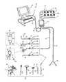
- FIG. 1is a perspective view of an exemplary surgical system 10 capable of neurophysiologic assessments together with ultrasound monitoring to aimed to safely access the spine and properly implant pedicle screws for fixation.
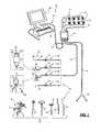
- FIG. 2is a block diagram of the surgical system 20 shown in FIG. 1 ;
- FIG. 3is a graph illustrating an exemplary single pulse stimulation signal according to one embodiment of the present invention.
- FIG. 4is a graph illustrating an exemplary multipulse stimulation signal according to one embodiment of the present invention.
- FIG. 5is a graph illustrating an exemplary EMG response to the stimulus of FIG. 3 or 4 according to one embodiment of the present invention
- FIG. 6is a graph illustrating a plot of peak-to-peak voltage (Vpp) for each given stimulation current level (I Stim ) forming a stimulation current pulse train according to the present invention (otherwise known as a “recruitment curve”);
- FIGS. 7A-7Dare graphs illustrating the fundamental steps of a rapid current threshold-hunting algorithm according to one embodiment of the present invention.
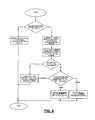
- FIG. 8is a flowchart illustrating a method by which the algorithm may omit a stimulation and proceed to the next current according to one aspect of the present invention
- FIGS. 9A-9Care graphs illustrating use of the threshold hunting algorithm of FIG. 7 and further omitting stimulations when the likely result is already clear from previous data according to one aspect of the present invention.
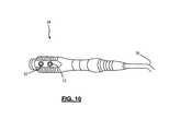
- FIG. 10is an illustration of a stimulation handpiece for coupling surgical accessories to the neuromonitoring system 10 according to one embodiment of the present invention
- FIG. 11an of a screw test probe coupled to the stimulation handpiece of FIG. 10 illustration according to one embodiment of the present invention
- FIG. 12is an illustration of a stimulation clip coupled to the stimulation handpiece of FIG. 10 according to one embodiment of the present invention.
- FIG. 13is a side view of the stimulation probe of FIG. 11 positioned over a stimulation target site and wherein the distal tip of the probe member and the stimulation target site are included in the camera's field of view;
- FIG. 14is an exemplary screen view of the Basic Screw Test mode for performing pedicle integrity assessments according to one embodiment of the present invention.
- FIG. 15is an exemplary screen view of the Difference Screw Test mode for performing pedicle integrity assessments according to one embodiment of the present invention.
- FIG. 16is an exemplary screen view of the Dynamic Screw Test mode for performing pedicle integrity assessments according to one embodiment of the present invention.
- FIG. 17is an exemplary screen view of the MaXcess Detection mode for detecting nerve presence during spinal access according to one embodiment of the present invention.
- FIG. 18is side view of a tap member coupled to the system for nerve monitoring via an electric coupling device and incorporating an ultrasound transducer for intraosteal ultrasound imaging according to one aspect of the present invention
- FIG. 19is side view of a pedicle access probe/bone awl coupled to the system for nerve monitoring via an electric coupling device and incorporating an ultrasound transducer for intraosteal ultrasound imaging according to one aspect of the present invention
- FIG. 20is a close up side view of the distal end of the tap member of FIG. 18 with a cutaway exposing an integrated ultrasound transducer for use according to one embodiment of the present invention
- FIG. 21is an overhead view of one embodiment of a transducer for use according to one embodiment of the present invention, having 64 elements arrayed radially for generating 360 degree images;
- FIG. 22is an illustration showing the general makeup of various bone regions comprising the spinal pedicle
- FIG. 23is an illustration of tap member of FIG. 18 forming a pilot hole along a preferred trajectory utilizing nerve monitoring and ultrasound imaging to maintain the trajectory;
- FIG. 24is a graphical representation of an ultrasound image showing the position of a surgical instrument within the interior pedicle during pedicle integrity testing
- FIG. 25is a graphical representation of an ultrasound image showing the position of a surgical access component relative to a nerve during nerve detection
- FIG. 26is an exemplary screen view of the Basic Screw Test mode for performing pedicle integrity assessments with concurrent use of ultrasound according to one embodiment of the present invention
- FIG. 27is an exemplary screen view of the Difference Screw Test mode for performing pedicle integrity assessments with concurrent use of ultrasound according to one embodiment of the present invention
- FIG. 28is an exemplary screen view of the Dynamic Screw Test mode for performing pedicle integrity assessments with concurrent use of ultrasound according to one embodiment of the present invention
- FIG. 29is an exemplary screen view of the MaXcess Detection mode for detecting nerve presence during spinal access with concurrent use of ultrasound according to one embodiment of the present invention.
- the present inventionis directed towards enabling safe and reproducible spinal surgery by aiding in, among other things, access to a target site in the spine (including but not necessarily limited to a pedicle) and pedicle screw implantation (including but not necessarily limited to formation and preparation of pilot holes and screw placement).
- a target site in the spineincluding but not necessarily limited to a pedicle
- pedicle screw implantationincluding but not necessarily limited to formation and preparation of pilot holes and screw placement.
- FIG. 1illustrates, by way of example only, a surgical system 10 capable carrying neurophysiologic assessment functions including, but not necessarily limited to, Basic, Difference, and Dynamic Screw Tests (pedicle integrity testing), Detection (nerve proximity testing during surgical access) and Free Run EMG (detection of spontaneous muscle activity, may be conducted in any mode).
- the surgical system 10is capable of performing ultrasound imaging to aid in intraoperative guidance of surgical instrumentation through bone, and in particular, through the cancellous bone forming the interior region of the pedicle as well as enhancing nerve detection. It is expressly noted that, although described herein largely in terms of use in spinal surgery, the surgical system 10 and related methods of the present invention are suitable for use in any number of additional surgical procedures where neurological impairment is a concern.
- the neuromonitoring system 10includes a control unit 12 , a patient module 14 , an EMG harness 16 , including eight pairs of EMG electrodes 18 and a return electrode 22 coupled to the patient module 14 , and one or more of a host of surgical accessories 24 capable of being coupled to the patient module 14 (preferably via a stimulation handpiece 28 and accessory cables 26 ), and a pair of peripheral nerve stimulation (PNS) electrodes (one positive and one negative) 29 also coupled to the patient module 14 .
- PNSperipheral nerve stimulation
- the surgical accessories 24may include, but are not necessarily limited to, devices for performing pedicle screw tests (such as a screw test probe 30 , tap member 32 , bone awl 34 ), surgical access components (such as a K-wire 36 , one or more dilating cannula 38 , 40 , a tissue retractor assembly 42 ), and neural pathology monitoring devices (such as a nerve root retractors 44 , 45 ), any of which may also be fitted with one or more ultrasound transducers 55 for imaging of surrounding tissue during use.
- the neuromonitoring system 10accomplishes neuromonitoring by having the control unit 12 and patient module 14 cooperate to send stimulation signals to one or more stimulation electrodes or electrode regions on the various surgical accessories, while sensors detect muscle activity caused by the stimulation signal.
- the control unit 12includes a touch screen display 46 and a base 48 , which collectively contain the essential processing capabilities for controlling the neuromonitoring system 10 .
- the touch screen display 26is preferably equipped with a graphical user interface (GUI) capable of communicating information to the user and receiving instructions from the user.
- GUIgraphical user interface
- the base 48contains computer hardware and software that commands the stimulation and ultrasound sources, receives digitized signals and other information from the patient module 14 , processes EMG responses, performs ultrasound image processing, and displays the processed data to the operator via the display 46 .
- the primary functions of the software within the control unit 12include receiving user commands via the touch screen display 46 , activating stimulation in the requested mode (Basic Screw Test, Difference Screw Test, Dynamic Screw Test, MaXcess Detection), processing EMG signal data according to defined algorithms, activating ultrasound signaling, processing ultrasound signal data into viewable images, displaying received parameters and processed data, and monitoring system status.
- the patient module 14is connected via a data cable 50 (or optionally via wireless communication) to the control unit 12 , and contains the electrical connections to all electrodes, EMG signal conditioning circuitry, stimulator drive and steering circuitry, ultrasound signal conditioning and receiving circuitry and a digital communications interface to the control unit 12 .
- the control unit 12is situated outside but close to the surgical field (such as on a cart adjacent the operating table) such that the display 46 is directed towards the surgeon for easy visualization.
- the patient module 14should be located between the patient's legs, or may be affixed to the end of the operating table at mid-leg level using a bedrail clamp. The position selected should be such that the EMG leads surgical accessories 24 can reach their farthest desired location without tension during the surgical procedure.
- the information displayed to the user on the display 46may include, but is not necessarily limited to, alpha-numeric and/or graphical information regarding any of the requested modes (e.g., Twitch Test, Free-Run EMG, Screw Test (Basic, Difference, Dynamic), Detection, and Nerve Retractor), myotome/EMG levels, stimulation levels, past stimulation events, stimulation site images, ultrasound images, etc. . . .
- this informationmay include at least some of the following components (depending on the active mode) as set forth in Table 1:
- Mode Indicator Graphics and/or nameto indicate the currently active mode (Detection, Basic Screw Test, Dynamic Screw Test, Difference Screw Test, Free- Run EMG, Twitch Test, Nerve Retractor, MEP, SSEP).
- Graphics and/or namemay also be displayed to indicate the instrument in use, such as the dilator, K-wire, retractor blades, screw test instruments, and associated size information, if applicable, of the cannula, with the numeric size. If no instrument is in use, then no indicator is displayed.
- Stimulation BarA graphical stimulation indicator depicting the present stimulation status (i.e. on or off and stimulation current level) Sequence Bar Shows the last seven stimulation results and provides for annotation of results.
- EMG waveformsEMG waveforms may be optionally displayed on screen along with the stimulation results.
- the neuromonitoring functionality of the neuromonitoring system 10is based on assessing the evoked response of the various muscle myotomes monitored by the system 10 in relation to a stimulation signal transmitted by the system 10 (via patient module 14 ). This is best shown in FIG. 3-5 , wherein FIG. 5 illustrates the resulting EMG of a monitored myotome in response to one of the exemplary single pulse stimulation signal shown in FIG. 3 and the multiple pulse stimulation signal shown in FIG. 4 .
- the EMG responsesprovide a quantitative measure of the nerve depolarization caused by the electrical stimulus.
- EMG response monitoringis accomplished via 8 pairs EMG electrodes 18 (placed on the skin over the muscle groups to be monitored), a common electrode 20 providing a ground reference to pre-amplifiers in the patient module 14 , and an anode electrode 22 providing a return path for the stimulation current.
- EMG electrodes 18placed on the skin over the muscle groups to be monitored
- common electrode 20providing a ground reference to pre-amplifiers in the patient module 14
- an anode electrode 22providing a return path for the stimulation current.
- One exemplary EMG electrode for use with the system 10is a dual surface electrode which is shown and described in detail in the commonly owned and co-pending U.S. patent application Ser. No. 11/048,404, entitled “Improved Electrode System and Related Methods,” filed on Jan. 31, 2005, which is expressly incorporated by reference into this disclosure as if set forth in its entirety herein.
- EMG electrode placementdepends on a multitude of factors, including for example, the spinal level and particular nerves at risk and user preference, among others.
- an exemplary EMG configurationis described for Lumbar surgery in Table 2, Thoracolumbar surgery in Table 3, and Cervical surgery in Table 4 below:
- a basic premise underlying the methods employed by the system 10 for much of the neurophysiologic monitoring conductedis that neurons and nerves have characteristic threshold current levels (I Thresh ) at which they will depolarize, resulting in detectable muscle activity. Below this threshold current, stimulation signals will not evoke a significant EMG response.
- a significant EMG responseis defined as having a V pp of approximately 100 uV.
- I ThreshThe lowest stimulation signal current, I slim that evokes this threshold voltage (V Thresh ) is called I Thresh .
- Finding I threshis useful in making neurophysiologic assessments because it provides a relative indication as to the degree of communication between a stimulation signal and nerve tissue. For example, as the degree of electrical communication between a stimulation signal and a nerve decreases, I thresh will increase. Conversely, as the degree of communication between the stimulation signal and a nerve increases, I thresh will decrease.
- the neuromonitoring system 10capitalizes on and enhances the information derived from I thresh by (a) employing methods designed to find I thresh quickly, accurately, and efficiently; (b) analyzing I thresh according to predetermined safety indicator levels; and (c) displaying I thresh and related safety indication data in a simple and meaningful way.
- the surgeonmay detect early on any problem or potential problem and then act to avoid and/or mitigate the situation.
- an excessively high I thresh or an increase over a previous I thresh measurement during Nerve Retractor modemay indicate a deterioration of nerve root function caused by excessive and/or prolonged retraction.
- a low I thresh valuemay indicate a breach in the pedicle, or the close proximity of a nerve, respectively.
- the system 10may employ a variety of suitable algorithms and techniques which are described in detail in the “NeuroVision Applications,” all of which are incorporated by reference below, as if they were set forth herein in their entireties.
- One exemplary threshold hunting algorithmillustrated by way of example only in FIGS. 7A-7D , is described hereafter in only brief detail.
- the threshold hunting algorithmutilizes a bracketing method and a bisection method to find I thresh .
- the bracketing methodfinds a range (bracket) of stimulation currents that must contain I thresh .
- the algorithmdirects stimulation to begin at a predetermined current level (based on the selected function). For each subsequent stimulation, the current level is doubled from the previous current level.
- V threshe.g. 100 uV.
- the initial bracketis successively reduced via the bisection method to a predetermined width. This is accomplished by applying a first bisection stimulation current that bisects (i.e. forms the midpoint of) the initial bracket. If this first bisection stimulation current recruits, the bracket is reduced to the lower half of the initial bracket. If this first bisection stimulation current does not recruit, the bracket is reduced to the upper half of the initial bracket. This process is continued for each successive bracket until I thresh is bracketed by stimulation currents separated by the predetermined width.
- the midpoint of this final bracketmay be defined as I thresh ; however, any value falling within the final bracket may be selected as I thresh without departing from the scope of the present invention.
- stimulationsmay stop after I thresh is determined for the channel possessing the lowest I thresh .
- functionse.g. Screw Tests and Detection
- the hunting algorithmmay employ additional methods allowing it to omit certain stimulations, thereby reducing the number of stimulations and time required to obtain an I thresh value on each channel.
- I threshis still found using the bracketing and bisection methods described above, however the algorithm will omit stimulations for which the result is predictable from data previously acquired.
- the algorithmproceeds as if the stimulation had taken place. This permits the algorithm to proceed to the next required stimulation immediately, without a time delay inherently associated with each stimulation signal.
- the algorithmmay confirm previously obtained I thresh values (e.g. by stimulation at current levels just below and at/or just above I thresh and determining whether the resulting responses are consistent with the previously acquired I thresh value), rather than initiating stimulations from the beginning each time a function is performed.
- the various functional modes of the neuromonitoring system 10may include the Basic Screw Test, Difference Screw Test, Dynamic Screw Test, MaXcess® Detection, and Free-run EMG, all of which will be described briefly below.
- the Basic Screw Test, Difference Screw Test, and Dynamic Screw Test modesare designed to assess the integrity of bone (e.g. pedicle) during all aspects of pilot hole formation (e.g., via an awl), pilot hole preparation (e.g. via a tap), and screw introduction (during and after). These modes are described in greater detail in Int'l Patent App. No. PCT/US02/35047 entitled “System and Methods for Performing Percutaneous Pedicle Integrity Assessments,” filed on Oct.
- the MaXcess® Detection modeis designed to detect the presence of nerves during the use of the various surgical access instruments of the neuromonitoring system 10 , including the k-wire 62 , dilator 64 , cannula 66 , 68 , retractor assembly 70 . This mode is described in greater detail within Int'l Patent App. No PCT/US02/22247, entitled “System and Methods for Determining Nerve Proximity, Direction, and Pathology During Surgery,” filed on Jul.
- one or more of the surgical accessories 24including, but not necessarily limited to screw test probe 30 , tap member 32 , bone awl 34 , k-wire 36 , dilating cannulae 38 , 40 , retractor assembly 42 , by way of fixed or releasable linkage to a stimulation handpiece 28 .
- FIG. 10there is shown one exemplary embodiment of a stimulation handpiece 28 .
- Stimulation handpiece 28is communicatively linked to the patient module 14 via accessory cable 26 .
- Stimulation handpiece 28directs stimulation signals from the patient module 14 to the surgical accessories 24 . Thereafter the stimulation signal preferably exits one or more electrode regions formed at or near the distal ends of the surgical accessories 24 .
- Stimulation handpiece 28may be equipped with one or more stimulation buttons 52 for selectively applying electrical stimulation to the attached surgical accessory 24 (according to the selected mode and hunting algorithm discussed above).
- the one or more stimulation buttons 52are preferably positioned along stimulation handpiece 28 such that the one or more buttons 52 may preferably be manipulated using the thumb and/or one or more fingers of the hand in which handpiece 28 is held.
- Various surgical accessories 24 that may be coupled to the stimulation handpiece 28will be discussed in more detail with regard to the neurophysiologic assessment modes performed by the neuromonitoring system 10 .
- the neuromonitoring system 10may test the integrity of pedicle holes (during and/or after formation) and/or screws (during and/or after introduction) via the Basic Screw test, Difference Screw Test, and/or Dynamic Screw Test modes.
- a screw test probe 30such as that illustrated in FIG. 11 , is used to direct stimulation signals to a pilot hole prior to screw installation, or a screw head after screw installation.
- Screw test probe 30may be coupled to stimulation handpiece 28 and includes an elongated probe member 54 and a ball-tipped end 56 . The ball-tipped end 56 is inserted through the surgical corridor to the stimulation target site (e.g. pilot hole and or screw head).
- a stimulation button 52may be pressed to initiate stimulation.
- the insulating character of bonewill prevent the stimulation current, up to a certain amplitude, from communicating with the nerve, thus resulting in a relatively high I thresh , as determined via the threshold hunting algorithm described above.
- the current density in the breach areawill increase to the point that the stimulation current will pass through to the adjacent nerve roots and they will depolarize at a lower stimulation current, thus I thresh will be relatively low. Details and results of the Basic Screw test results and may be conveyed to the user on display 46 .
- a baseline threshold valueis determined by directly stimulating a nerve.
- Screw test probe 30may preferably be used, and the probe is advanced through the surgical corridor to the surgical target site (i.e. the nerve to be directly stimulated).
- Button 52 on the stimulation handpiece 28is pressed to initiate stimulation and a baseline threshold is established.
- Screw test probe 30may then be maneuvered to the next stimulation target site (e.g. pilot hole or screw head) and stimulation is initiated to determine the actual threshold value I thresh .
- the actual thresholdis compared to the baseline threshold.
- the difference between the actual and baseline thresholdsis calculated to provide an indication of the safety level. Details and results, including the baseline, actual, and difference thresholds among other things may be displayed for the user on GUI display 46 .
- Dynamic Screw Test modecontinuously monitors threshold values while one or more surgical accessories are in use, for example forming a pilot hole.
- an electric coupling devicesuch as, by way of example only, stimulation clip 58 is coupled to stimulation handpiece 28 , as illustrated in FIG. 12 .
- the electric coupling devicecouples surgical accessories 24 (such as for example, a tap member 32 or a bone awl 34 ) to the neuromonitoring system 10 such that stimulation signals may be transmitted through the tool during use.
- surgical accessories 24such as for example, a tap member 32 or a bone awl 34
- screw testingmay be performed continuously during pilot hole formation by coupling the bone awl 34 to the neuromonitoring system 10 , and during pilot hole preparation by coupling the tap 32 to the system 10 .
- the algorithmmay preferably confirm the earlier results by switching back and forth between stimulation signals just above and just below I thresh . If the expected results are not obtained then the algorithm may transition back into the bracketing and bisection steps. Details and results of the Dynamic Screw test results and may be conveyed and continuously updated on display 46 .
- stimulation clip 58utilizes a spring-loaded plunger to hold the surgical tool and transmit the stimulation signal.
- the plunger 60is composed of a conductive material such as metal.
- a nonconductive housing 62partially encases the plunger 60 about its center. Extending from the housing 62 is an end plate 64 .
- An electrical cable 66connects the stimulation clip 58 to the stimulation handpiece 28 .
- a spring(not shown) is disposed within the housing 62 such that in a natural or “closed” state the plunger 60 is situated in close proximity to the endplate 64 .
- Exerting a compressive force on the springcauses a gap between the end plate 64 and the plunger 60 to widen to an “open” position, thereby allowing insertion of a surgical tool (e.g. tap member 32 and awl 34 ) between the end plate 64 and plunger 60 .
- Releasing the cable 66allows the spring to return to a “closed” position, causing the plunger 60 to move laterally back towards the endplate such that a force is exerted upon the surgical instrument and thereby holds it in place between the endplate 64 and the plunger 60 . This is best viewed in FIG.
- stimulation clip 58is linked to stimulation handpiece 28 (via cable 66 ) on one end and coupled around tap member 32 on the other end.
- stimulation clip 58(or clap 68 described below) may be linked directly to patient module 14 rather than stimulation handpiece 28 , in which case stimulation may be initiated and/or stopped from the GUI display 46 .
- the electrical stimulusmay be initiated by pressing one of stimulation buttons 52 and thereafter the stimulation signal may be passed from the handpiece 28 through the cable 66 and plunger 60 to the tap member 32 (or other surgical accessory 24 ).
- Stimulation clamp 68is comprised of two prongs hingedly coupled at a coupling point 70 such that the clamp 68 includes an attachment end 72 and a non-attachment end 74 .
- a stimulation electrode 76is disposed on the attachment end 72 and communicates with electric cable 66 extending from the non-attachment end 74 to the handpiece 28 .
- the prong ends at the attachment end 72touch. Depressing the prongs at the non-attachment end 74 in a direction towards one another causes a gap to form between the prong ends at the attachment end 72 .
- FIG. 14is an exemplary screen view of the Basic Screw Test mode for display on display 46 .
- FIG. 15illustrates an exemplary screen view of the Difference Screw Test mode for display on display 46 .
- FIG. 16is an exemplary screen view of the Dynamic Screw Test mode for display on display 46 .
- one or more channel tabsmay be highlighted using a color-code to indicate status of the corresponding nerve, and thus the relative safety level determined by the system 10 .
- the channel with the “worst” (lowest) levelwill preferably be enlarged and that myotome name 76 will be displayed, as well as graphically depicted on the spine diagram 78 .
- a vertical bar chart 80may also be shown to depict the stimulation current required to evoke a significant response for the selected channel.
- a large numerical readout 82may also indicate the value of the stimulation result.
- the display of the stimulation resultmay be augmented with a color code utilizing the colors green, yellow, and red to enhance the understandability of the result and quickly indicate to the surgeon the level of safety determined by the system 10 . Red may be used to indicate an I thresh level below a predetermined unsafe level.
- Yellowmay be used to indicate an I thresh that falls in between predetermined safe and unsafe levels.
- Greenmay represent an I thresh within the range predetermined as safe.
- the threshold resultsmay be replaced with, or more preferably, augmented with a display of the actual waveform for each channel, as well as audible sounds distinctive to each level of safety (safe, unsafe, in between).
- the neuromonitoring system 10may perform nerve proximity testing, via the MaXcess® Detection mode, to ensure safe and reproducible access to surgical target sites.
- the system 10detects the existence of neural structures before, during, and after the establishment of an operative corridor through (or near) any of a variety of tissues having such neural structures, which, if contacted or impinged, may otherwise result in neural impairment for the patient.
- the surgical access components 36 - 40are designed to bluntly dissect the tissue between the patient's skin and the surgical target site. Access components 36 - 40 preferably utilize stimulation handpiece 28 and stimulation clip 58 (in the same manner as described above and shown in FIG. 12 ) to link to the system 10 .
- Cannulae or dilators of increasing diametermay be advanced towards the target site until a sufficient operating corridor is established.
- electrical stimulation signalsare transmitted through the stimulation handpiece 28 to the distal end of the cannulae where they are emitted from an electrode region.
- the stimulation signalwill stimulate nerves in close proximity to the stimulation electrode and the corresponding EMG response is monitored.
- the stimulation current (I stim ) required to evoke a muscle responsedecreases.
- I threshis calculated (using the threshold hunting algorithm described above) which provides a measure of the communication between the stimulation signal and the nerve and thus giving a relative indication of the proximity between access components and nerves.
- tissue retraction assembly 42may be coupled to the system 10 (via stimulation clip 58 or claim 68 ) and employed to provide safe and reproducible access to a surgical target site.
- Tissue retraction assembly 42 and various embodiments and uses thereofhave been shown and described in commonly assigned U.S. Pat. No. 7,905,840, entitled “Surgical Access System and Related Methods,” issued on Mar. 15, 2011, the entire contents of which are expressly incorporated by reference as if set forth herein in their entirety.
- the neuromonitoring system 10may perform nerve proximity testing during the creation of an operative corridor via a direct lateral, retroperitoneal approach to the anterior column of the spine with the patient preferably placed in a lateral, decubitus position on the operating table.
- a lateral incision of sufficient size to receive a distal end of an initial dilator 38is made.
- the distal end of the initial dilator 38is advanced in a substantially lateral direction from the lateral incision location through the subcutaneous layers, muscle layers, and retroperitoneal space, and finally through the psoas muscle toward the intervertebral disc space at or near the surgical target site.
- one or more additional surgical access componentsmay be guided over the initial dilator 38 for the purpose of further dilating the tissue down to the surgical target site and/or establishing an operative corridor to the surgical target site.
- FIG. 17An exemplary screen display of the Detection mode for display on display 46 is illustrated by way of example only in FIG. 17 . Similar to the screw test modes, upon execution of the algorithm, one or more channel tabs may be highlighted using a color-code to indicate status of the corresponding nerve, and thus the relative safety level determined by the system 10 .
- the channel with the “worst” (lowest) levelwill preferably be enlarged and that myotome name— 76 will be displayed, as well as graphically depicted on the spine diagram 78 .
- a vertical bar chart 80may also be shown to depict the stimulation current required to evoke a significant response for the selected channel.
- a large numerical readout 82may also indicate the value of the stimulation result.
- the display of the stimulation resultmay be augmented with a color code utilizing the colors green, yellow, and red to enhance the understandability of the result and quickly indicate to the surgeon the level of safety determined by the system 10 .
- Redmay be used to indicate an I thresh level below a predetermined unsafe level.
- Yellowmay be used to indicate an I thresh that falls in between predetermined safe and unsafe levels.
- Greenmay represent an I thresh within the range predetermined as safe.
- the threshold resultsmay be replaced with, or more preferably, augmented with a display of the actual waveform for each channel, as well as audible sounds distinctive to each level of safety (safe, unsafe, in between).
- the neuromonitoring system 10may also conduct free-run EMG monitoring while the system is in any of the above-described modes.
- Free-run EMG monitoringcontinuously listens for spontaneous muscle activity that may be indicative of potential danger.
- the system 10may automatically cycle into free-run monitoring after 5 seconds (by way of example only) of inactivity. Initiating a stimulation signal in the selected mode will interrupt the free-run monitoring until the system 10 has again been inactive for five seconds at which time the free-run begins again.
- Stimulated and/or Free-run results for any functionmay be replaced with, or more preferably, augmented with a display of the actual waveform for each channel, as well as audible sounds distinctive to each level of safety (safe, unsafe, in between).
- the system 10may be further equipped to conduct and display ultrasound imaging of proximate body tissues (e.g. bone during pilot hole formation and preparation and/or screw implantation and nerves and/or vasculature during surgical access).
- proximate body tissuese.g. bone during pilot hole formation and preparation and/or screw implantation and nerves and/or vasculature during surgical access.
- the system 10may employ intraoperative ultrasound tailored to allow use within bone, such as, by way of example only, the ultrasound system described in U.S. Pat. No. 6,579,244, entitled “Intraosteal Ultrasound During Surgical Implantation.”
- at least one ultrasound transducer 55may be deployed to the surgical target site during surgery.
- acoustic signals of a predetermined frequencyranging between 50 kHz and 16 MHz, are emitted from the transducer(s) 55 through the surrounding body tissue.
- the signalsreflect off tissue boundaries and are thereafter received back at the transducer, converted into electric signals, and processed by the control unit 12 into viewable images.
- the imagesmay be viewed on the screen display 26 .
- At least one transduceris mounted on or within one or more of the surgical accessories 24 (such as screw test probe 30 , dilating cannula 38 , 40 , or retraction assembly 42 , shown in FIG. 1 ) and/or one or more surgical instruments engageable with the system 10 via electric coupling device 58 , 68 (such as a tap member 34 or pedicle access probe 32 , shown in FIG. 18 and FIG. 19 , respectively).
- a separate transducermay be provided and advanced to the surgical target site alone or in conjunction with one or more of the above accessories or instruments, either by advancing alongside or through an interior lumen formed in the instrument for such purpose.
- ultrasound transducers 55may be deployed at the distal end of various bone screws, including, but not necessarily limited to pedicle screws and/or facet screws, for enabling ultrasound imaging of the surrounding bone during screw implantation.
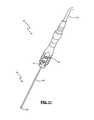
- FIG. 20depicts in more detail the incorporation of the ultrasound transducer 55 within tap member 34 , according to one exemplary embodiment of the present invention.
- ultrasound transducer 55is incorporated in the distal end of tap member 34 .
- the transducer 55may be coupled to the patient module via electric cable, such as by way of example, cable 59 .
- the surgical system 10utilizes a 64-element array transducer, such as that available and in use with a number of commercially developed products from Volcano Corp. (Rancho Cordova, Calif.).
- the transducer elements 57are arrayed in a circular pattern providing for 360° radial imaging of surrounding tissue.
- forward looking transducersmay also be employed for additional imaging of tissue lying in front of the surgical instrument.
- transducer 55both transmits and receives the acoustic signals.
- a transducer incorporated in a surgical accessorymay transmit acoustic signals to a receiver positioned in the operating room (outside the patients body) and conversely, a transducer positioned in the operating room may transmit acoustic signals to a receiver incorporated into a surgical accessory.
- a basic principle underlying the effective use of ultrasound during and/or after pilot hole formation and preparationis the distinctive acoustical characteristics of bone relative to other soft tissues in the body, and more importantly, the varying acoustical characteristics exhibited by bone itself, depending upon its different properties, such as (by way of example only) the type of bone (i.e. cortical or cancellous), bone density, and bone composition.
- Different acoustical characteristicscan include, among others, the velocity, amplitude, and attenuation of sound waves as they pass through tissue.
- the present inventionmakes advantageous use of this information, as well as the general makeup of the boney tissue within the pedicle, to assist surgeons in guidance of surgical instrumentation (including but not limited to tap member 34 and pedicle access probe/awl 36 ) through the cancellous bone of the interior pedicle and into the vertebral body without breaching the cortical wall.
- surgical instrumentationincluding but not limited to tap member 34 and pedicle access probe/awl 36
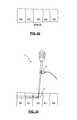
- the pediclegenerally comprises a hard outer region 420 of dense cortical bone and center region 400 of softer, less dense cancellous bone, separated by one or more middle regions 410 .
- the bone in region 410is generally less dense than outer region 420 but more dense than center region 410 .
- the preferred trajectory for pedicle screw placementis through the soft cancellous bone of the center region 400 , thereby avoiding a breach of the pedicle wall.
- at least one of the tap member 34 , pedicle access probe 36 , or screw test probe 30is advanced through the pedicle. As illustrated in FIG. 23 , acoustic signals are emitted from the transducer 55 and travel through the bone.
- the ultrasound scanis conducted radially about the surgical instrument thus generating a 360° image of the pedicle relative to the distal end of the surgical instrument, as seen in FIG. 24 . From the screen display 46 the surgeon can visually monitor the relative position of the instrument within the pedicle and thus make any necessary adjustments should the instrument position stray from the desired pathway.
- the transducer 55may be substantially located on just one portion of the distal end and the ultrasound scan may be directed by rotating the instrument about its longitudinal axis or any desired portion thereof.
- ultrasoundmay be used to determine various properties and/or conditions of bone (via any of a number of suitable methods known to the prior art which may be implemented by the system 10 ) which may also provide useful information.
- cracks in the pedicle bonemay be detected using ultrasound.
- the system 10may thus detect a breach in the outer wall of the pedicle by ultrasound detection as well as by the nerve monitoring described above. Additional warning indicia such as graphics and/or audible tones may be employed to warn of any danger detected by the system 10 using ultrasound.
- the system 10may utilize ultrasound to determine the density of the bone instrument 24 is in contact with. In the event the instrument encounters cortical bone an auditory or visual alert may be initiated thereby providing additional warning of impending breach if the current trajectory is maintained.
- Ultrasound during surgical accessmay also be used to enhance the nerve detection function described above and proceeds along the same premise as that described for imaging bone.
- Acoustic signalsgenerally in the range of 2 MHz-16 MHZ for nerve imaging, are emitted from the transducer 55 located on or within the surgical access components (such as, cannulae 38 , 40 , and/or retraction assembly 42 ).
- the signalsreflect of tissue boundaries, such as the interface between fat and muscle or muscle and nerves, and are thereafter received and processed to form a viewable image of the tissue relative to the transducer, which is displayed on screen display 46 .
- Nervesare distinguished from other tissue based on their shape and/or color on the image, as illustrated in FIG. 25 . By way of example only, nerves generally appear as round or oval shaped and are generally brighter than the surrounding tissue.
- Ultrasoundmay be utilized on system 10 in conjunction with one the neurophysiologic assessment functions, or, it may be used as a stand alone feature.
- ultrasoundis preferably activated from the GUI display 46 by selecting the appropriate command.
- the ultrasound imageis preferably displayed together with the nerve monitoring data thereby allowing the user to receive all the useful information provided by the system 10 at one time without the need to switch between screen views.
- FIG. 26 - 28illustraterate, by way of example only, an exemplary screen display for the Basic, Difference, and Dynamic screw test modes, respectively, with the combined ultrasound imaging image 84 .
- the ultrasound displayincludes colorized tissue boundaries.
- the soft cancellous bone 400may be shown in green representing the preferred instrument positioning.
- the middle region 410may be represented in yellow and the cortical bone in red.
- the distal end of the surgical instrumentis represented, by way of example only, as a target finder 430 .
- FIG. 29illustrates an exemplary screen display of the nerve detection function when ultrasound imaging is in use.
- neurophysiologic assessment data and/or ultrasound images captured by the system 10may be viewable by persons not present in the operating room. It is contemplated that the data and images may be transmitted to one or more remote locations and viewable by authorized persons. This may be accomplished by any number of data transmission methods. In one example, the images may be transmitted to a remote user via remote monitoring software such as that described in detail in the commonly owned and co-pending U.S. patent application Ser. No. 11/418,589, entitled “System and Methods for Performing and Monitoring Neurophysiologic Assessments,” filed on May 5, 2006, the entire contents of which are incorporated by reference herein as if set forth in its entirety.
- the present inventionmay be implemented using any combination of computer programming software, firmware or hardware.
- the computer programming code(whether software or firmware) according to the invention will typically be stored in one or more machine readable storage mediums such as fixed (hard) drives, diskettes, optical disks, magnetic tape, semiconductor memories such as ROMs, PROMs, etc., thereby making an article of manufacture in accordance with the invention.
- the article of manufacture containing the computer programming codeis used by either executing the code directly from the storage device, by copying the code from the storage device into another storage device such as a hard disk, RAM, etc. or by transmitting the code on a network for remote execution.
- a hard disksuch as a hard disk, RAM, etc.
Landscapes
- Health & Medical Sciences (AREA)
- Life Sciences & Earth Sciences (AREA)
- Surgery (AREA)
- Molecular Biology (AREA)
- Veterinary Medicine (AREA)
- Public Health (AREA)
- General Health & Medical Sciences (AREA)
- Animal Behavior & Ethology (AREA)
- Engineering & Computer Science (AREA)
- Biomedical Technology (AREA)
- Heart & Thoracic Surgery (AREA)
- Medical Informatics (AREA)
- Pathology (AREA)
- Biophysics (AREA)
- Physics & Mathematics (AREA)
- Nuclear Medicine, Radiotherapy & Molecular Imaging (AREA)
- Radiology & Medical Imaging (AREA)
- Gynecology & Obstetrics (AREA)
- Neurology (AREA)
- Orthopedic Medicine & Surgery (AREA)
- Rheumatology (AREA)
- Vascular Medicine (AREA)
- Surgical Instruments (AREA)
- Measurement And Recording Of Electrical Phenomena And Electrical Characteristics Of The Living Body (AREA)
Abstract
Description
| TABLE 1 | |
| Screen | |
| Component | Description |
| Spine Image | An image of the human body/skeleton showing the electrode placement |
| on the body, with labeled channel number tabs on each side (1-4 on the | |
| left and right). Left and right labels will show the patient orientation. | |
| The channel number tabs may be highlighted or colored depending on | |
| the specific function being performed. | |
| Myotome & | A label to indicate the Myotome name and corresponding Spinal |
| Level Names | Level(s) associated with the channel of interest. |
| Menu | A drop down navigation component for toggling between functions. |
| Display Area | Shows procedure-specific information including stimulation results. |
| Color Indication | Enhances stimulation results with a color display of green, yellow, or |
| red corresponding to the relative safety level determined by the system. | |
| Mode Indicator | Graphics and/or name to indicate the currently active mode (Detection, |
| Basic Screw Test, Dynamic Screw Test, Difference Screw Test, Free- | |
| Run EMG, Twitch Test, Nerve Retractor, MEP, SSEP). In an alternate | |
| embodiment, Graphics and/or name may also be displayed to indicate | |
| the instrument in use, such as the dilator, K-wire, retractor blades, | |
| screw test instruments, and associated size information, if applicable, | |
| of the cannula, with the numeric size. If no instrument is in use, then | |
| no indicator is displayed. | |
| Stimulation Bar | A graphical stimulation indicator depicting the present stimulation |
| status (i.e. on or off and stimulation current level) | |
| Sequence Bar | Shows the last seven stimulation results and provides for annotation of |
| results. | |
| EMG waveforms | EMG waveforms may be optionally displayed on screen along with the |
| stimulation results. | |
| Ultrasound Image | Ultrasound images of the tissue, including bone, acquired from |
| ultrasound transducers integrated into or used in cooperation with one | |
| or more of the surgical accessories. | |
| TABLE 2 |
| Lumbar |
| Spinal | ||||
| Color | Channel | Myotome | Nerve | |
| Red | Right | |||
| 1 | Right Vastus Medialis | Femoral | L2, L3, | |
| Orange | Right | |||
| 2 | Right Tibialis Anterior | Common Peroneal | L4, | |
| Yellow | Right | |||
| 3 | Right Biceps Femoris | Sciatic | L5, S1, | |
| Green | Right | |||
| 4 | Right Medial Gastroc. | Post Tibial | S1, | |
| Blue | Left | |||
| 1 | Left Vastus Medialis | Femoral | L2, L3, | |
| Violet | Left | |||
| 2 | Left Tibialis Anterior | Common Peroneal | L4, | |
| Gray | Left | |||
| 3 | Left Biceps Femoris | Sciatic | L5, S1, | |
| White | Left | |||
| 4 | Left Medial Gastroc. | Post Tibial | S1, S2 | |
| TABLE 3 |
| Thoracolumbar |
| Spinal | ||||
| Color | Channel | Myotome | Nerve | |
| Red | Right | |||
| 1 | Right Abductor | Median | C6, C7, C8, | |
| Pollicis Brevis | ||||
| Orange | Right | |||
| 2 | Right Vastus Medialis | Femoral | L2, L3, | |
| Yellow | Right | |||
| 3 | Right Tibialis Anterior | Common | L4, L5 | |
| Green | Right | |||
| 4 | Right Abductor Hallucis | Tibial | L4, L5, | |
| Blue | Left | |||
| 1 | Left Abductor | Median | C6, C7, C8, | |
| Pollicis Brevis | ||||
| Violet | Left | |||
| 2 | Left Vastus Medialis | Femoral | L2, L3, | |
| Gray | Left | |||
| 3 | Left Tibialis Anterior | Common | L4, L5 | |
| White | Left | |||
| 4 | Left Abductor Hallucis | Tibial | L4, L5, S1 | |
| TABLE 4 |
| Cervical |
| Color | Channel | Myotome | Nerve | Spinal |
| Red | Right | |||
| 1 | Right Deltoid | Axilliary | C5, | |
| Orange | Right | |||
| 2 | Right Flexor Carpi Radialis | Median | C6, C7, | |
| Yellow | Right | |||
| 3 | Right Abductor | Median | C6, C7, C8, | |
| Pollicis Brevis | ||||
| Green | Right | |||
| 4 | Right Abductor Hallucis | Tibial | L4, L5, | |
| Blue | Left | |||
| 1 | Left Deltoid | Axillary | C5, | |
| Violet | Left | |||
| 2 | Left Flexor Carpi Radialis | Median | C6, C7, | |
| Gray | Left | |||
| 3 | Left Abductor | Median | C6, C7, C8, | |
| Pollicis Brevis | ||||
| White | Left | |||
| 4 | Left Abductor Hallucis | Tibial | L4, L5, S1 | |
Claims (16)
Priority Applications (8)
| Application Number | Priority Date | Filing Date | Title |
|---|---|---|---|
| US11/528,981US8568317B1 (en) | 2005-09-27 | 2006-09-27 | System and methods for nerve monitoring |
| US14/063,184US20140051999A1 (en) | 2005-09-27 | 2013-10-25 | System and Methods for Nerve Monitoring |
| US14/881,091US10299756B1 (en) | 2005-09-27 | 2015-10-12 | System and methods for nerve monitoring |
| US16/384,936US11653894B2 (en) | 2005-09-27 | 2019-04-16 | System and methods for nerve monitoring |
| US16/875,018US11617562B2 (en) | 2005-09-27 | 2020-05-15 | System and methods for nerve monitoring |
| US16/875,033US11540804B2 (en) | 2005-09-27 | 2020-05-15 | System and methods for nerve monitoring |
| US16/875,025US11712218B2 (en) | 2005-09-27 | 2020-05-15 | System and methods for nerve monitoring |
| US16/875,040US12127877B2 (en) | 2005-09-27 | 2020-05-15 | System and methods for nerve monitoring |
Applications Claiming Priority (2)
| Application Number | Priority Date | Filing Date | Title |
|---|---|---|---|
| US72142505P | 2005-09-27 | 2005-09-27 | |
| US11/528,981US8568317B1 (en) | 2005-09-27 | 2006-09-27 | System and methods for nerve monitoring |
Related Child Applications (1)
| Application Number | Title | Priority Date | Filing Date |
|---|---|---|---|
| US14/063,184ContinuationUS20140051999A1 (en) | 2005-09-27 | 2013-10-25 | System and Methods for Nerve Monitoring |
Publications (1)
| Publication Number | Publication Date |
|---|---|
| US8568317B1true US8568317B1 (en) | 2013-10-29 |
Family
ID=49448540
Family Applications (8)
| Application Number | Title | Priority Date | Filing Date |
|---|---|---|---|
| US11/528,981ActiveUS8568317B1 (en) | 2005-09-27 | 2006-09-27 | System and methods for nerve monitoring |
| US14/063,184AbandonedUS20140051999A1 (en) | 2005-09-27 | 2013-10-25 | System and Methods for Nerve Monitoring |
| US14/881,091ActiveUS10299756B1 (en) | 2005-09-27 | 2015-10-12 | System and methods for nerve monitoring |
| US16/384,936Active2027-01-05US11653894B2 (en) | 2005-09-27 | 2019-04-16 | System and methods for nerve monitoring |
| US16/875,040Active2029-08-09US12127877B2 (en) | 2005-09-27 | 2020-05-15 | System and methods for nerve monitoring |
| US16/875,025Active2028-01-02US11712218B2 (en) | 2005-09-27 | 2020-05-15 | System and methods for nerve monitoring |
| US16/875,033Active2027-10-23US11540804B2 (en) | 2005-09-27 | 2020-05-15 | System and methods for nerve monitoring |
| US16/875,018Active2027-10-16US11617562B2 (en) | 2005-09-27 | 2020-05-15 | System and methods for nerve monitoring |
Family Applications After (7)
| Application Number | Title | Priority Date | Filing Date |
|---|---|---|---|
| US14/063,184AbandonedUS20140051999A1 (en) | 2005-09-27 | 2013-10-25 | System and Methods for Nerve Monitoring |
| US14/881,091ActiveUS10299756B1 (en) | 2005-09-27 | 2015-10-12 | System and methods for nerve monitoring |
| US16/384,936Active2027-01-05US11653894B2 (en) | 2005-09-27 | 2019-04-16 | System and methods for nerve monitoring |
| US16/875,040Active2029-08-09US12127877B2 (en) | 2005-09-27 | 2020-05-15 | System and methods for nerve monitoring |
| US16/875,025Active2028-01-02US11712218B2 (en) | 2005-09-27 | 2020-05-15 | System and methods for nerve monitoring |
| US16/875,033Active2027-10-23US11540804B2 (en) | 2005-09-27 | 2020-05-15 | System and methods for nerve monitoring |
| US16/875,018Active2027-10-16US11617562B2 (en) | 2005-09-27 | 2020-05-15 | System and methods for nerve monitoring |
Country Status (1)
| Country | Link |
|---|---|
| US (8) | US8568317B1 (en) |
Cited By (50)
| Publication number | Priority date | Publication date | Assignee | Title |
|---|---|---|---|---|
| US20130317340A1 (en)* | 2006-10-06 | 2013-11-28 | II Erich Wolf | Electromagnetic apparatus and method for nerve localization during spinal surgery |
| US20140277193A1 (en)* | 2013-03-14 | 2014-09-18 | Warsaw Orthopedic, Inc. | Bone fastener and methods of use |
| US20140288427A1 (en)* | 2009-04-03 | 2014-09-25 | James K. Wall | Devices and methods for tissue navigation |
| US20160089154A1 (en)* | 2014-09-26 | 2016-03-31 | DePuy Synthes Products, LLC | Surgical tool with feedback |
| US9700292B2 (en) | 2012-09-17 | 2017-07-11 | DePuy Synthes Products, Inc. | Systems and methods for surgical and interventional planning, support, post-operative follow-up, and functional recovery tracking |
| JP2017532077A (en)* | 2014-08-08 | 2017-11-02 | メドトロニック・ゾーメド・インコーポレーテッド | Wireless neural integrity monitoring system and device |
| US9949651B2 (en) | 2011-11-01 | 2018-04-24 | DePuy Synthes Products, Inc. | Intraoperative neurophysiological monitoring system |
| US10039915B2 (en) | 2015-04-03 | 2018-08-07 | Medtronic Xomed, Inc. | System and method for omni-directional bipolar stimulation of nerve tissue of a patient via a surgical tool |
| US10154826B2 (en) | 2013-07-17 | 2018-12-18 | Tissue Differentiation Intelligence, Llc | Device and method for identifying anatomical structures |
| US10258228B2 (en) | 2014-08-08 | 2019-04-16 | K2M, Inc. | Retraction devices, systems, and methods for minimally invasive spinal surgery |
| US10278686B2 (en) | 2010-09-20 | 2019-05-07 | DePuy Synthes Products, Inc. | Spinal access retractor |
| US20190142408A1 (en)* | 2017-11-14 | 2019-05-16 | Endovision Co., Ltd. | Method of unilateral biportal endoscopy and surgical instrument set used in same |
| US10321833B2 (en) | 2016-10-05 | 2019-06-18 | Innovative Surgical Solutions. | Neural locating method |
| US10339273B2 (en) | 2015-11-18 | 2019-07-02 | Warsaw Orthopedic, Inc. | Systems and methods for pre-operative procedure determination and outcome predicting |
| US10376209B2 (en) | 2013-09-20 | 2019-08-13 | Innovative Surgical Solutions, Llc | Neural locating method |
| US10376208B2 (en) | 2013-09-20 | 2019-08-13 | Innovative Surgical Solutions, Llc | Nerve mapping system |
| US10445466B2 (en) | 2015-11-18 | 2019-10-15 | Warsaw Orthopedic, Inc. | Systems and methods for post-operative outcome monitoring |
| US10449002B2 (en) | 2013-09-20 | 2019-10-22 | Innovative Surgical Solutions, Llc | Method of mapping a nerve |
| US10478096B2 (en) | 2013-08-13 | 2019-11-19 | Innovative Surgical Solutions. | Neural event detection |
| US10478097B2 (en) | 2013-08-13 | 2019-11-19 | Innovative Surgical Solutions | Neural event detection |
| US10687797B2 (en) | 2008-12-18 | 2020-06-23 | Howmedica Osteonics Corp. | Lateral access system for the lumbar spine |
| US10716536B2 (en) | 2013-07-17 | 2020-07-21 | Tissue Differentiation Intelligence, Llc | Identifying anatomical structures |
| US10849517B2 (en) | 2016-09-19 | 2020-12-01 | Medtronic Xomed, Inc. | Remote control module for instruments |
| US10870002B2 (en) | 2018-10-12 | 2020-12-22 | DePuy Synthes Products, Inc. | Neuromuscular sensing device with multi-sensor array |
| US10869616B2 (en) | 2018-06-01 | 2020-12-22 | DePuy Synthes Products, Inc. | Neural event detection |
| US11026627B2 (en) | 2013-03-15 | 2021-06-08 | Cadwell Laboratories, Inc. | Surgical instruments for determining a location of a nerve during a procedure |
| EP3761870A4 (en)* | 2018-03-05 | 2021-08-18 | EDGe Surgical, Inc. | HANDHELD DEVICES FOR USE IN MEDICAL SURGERY |
| US11168967B2 (en) | 2016-11-03 | 2021-11-09 | Edge Surgical, Inc. | Surgical depth instrument having neuromonitoring capabilities |
| US11166709B2 (en) | 2016-08-23 | 2021-11-09 | Stryker European Operations Holdings Llc | Instrumentation and methods for the implantation of spinal implants |
| US11177610B2 (en) | 2017-01-23 | 2021-11-16 | Cadwell Laboratories, ino. | Neuromonitoring connection system |
| US11191532B2 (en) | 2018-03-30 | 2021-12-07 | Stryker European Operations Holdings Llc | Lateral access retractor and core insertion |
| US11253182B2 (en) | 2018-05-04 | 2022-02-22 | Cadwell Laboratories, Inc. | Apparatus and method for polyphasic multi-output constant-current and constant-voltage neurophysiological stimulation |
| US11399777B2 (en) | 2019-09-27 | 2022-08-02 | DePuy Synthes Products, Inc. | Intraoperative neural monitoring system and method |
| US11413029B2 (en) | 2018-10-24 | 2022-08-16 | Stryker European Operations Holdings Llc | Anterior to psoas instrumentation |
| US11443649B2 (en) | 2018-06-29 | 2022-09-13 | Cadwell Laboratories, Inc. | Neurophysiological monitoring training simulator |
| US11464504B2 (en) | 2017-08-17 | 2022-10-11 | Stryker European Operations Holdings Llc | Lateral access bridges, shims and lighting including rod lighting |
| US11564674B2 (en) | 2019-11-27 | 2023-01-31 | K2M, Inc. | Lateral access system and method of use |
| US11564719B2 (en) | 2017-06-14 | 2023-01-31 | Edge Surgical, Inc. | Devices for minimally invasive procedures |
| US11678906B2 (en)* | 2019-09-09 | 2023-06-20 | Amplify Surgical, Inc. | Multi-portal surgical systems, cannulas, and related technologies |
| US11701086B1 (en) | 2016-06-21 | 2023-07-18 | Tissue Differentiation Intelligence, Llc | Methods and systems for improved nerve detection |
| US11950770B1 (en) | 2022-12-01 | 2024-04-09 | Amplify Surgical, Inc. | Multi-portal split cannulas, endoscopic hemostatic dispensers and surgical tools |
| US11980465B2 (en) | 2015-04-03 | 2024-05-14 | Medtronic Xomed, Inc. | System and method for omni-directional bipolar stimulation of nerve tissue of a patient via a bipolar stimulation probe |
| US11986341B1 (en) | 2016-05-26 | 2024-05-21 | Tissue Differentiation Intelligence, Llc | Methods for accessing spinal column using B-mode imaging to determine a trajectory without penetrating the the patient's anatomy |
| US11992227B2 (en) | 2018-03-05 | 2024-05-28 | Edge Surgical, Inc. | Handheld devices for use in medical procedures |
| US11992339B2 (en) | 2018-05-04 | 2024-05-28 | Cadwell Laboratories, Inc. | Systems and methods for dynamic neurophysiological stimulation |
| US12201436B2 (en) | 2014-08-08 | 2025-01-21 | Medtronic Xomed, Inc. | Wireless nerve integrity monitoring systems and devices |
| US12226319B2 (en) | 2019-09-09 | 2025-02-18 | Amplify Surgical, Inc. | Multi-portal surgical systems |
| US12268457B2 (en) | 2018-10-15 | 2025-04-08 | Mazor Robotics Ltd. | Versatile multi-arm robotic surgical system |
| US12274525B2 (en) | 2020-09-29 | 2025-04-15 | Mazor Robotics Ltd. | Systems and methods for tracking anatomical motion |
| US12343069B2 (en) | 2017-02-01 | 2025-07-01 | Avent, Inc. | EMG guidance for probe placement, nearby tissue preservation, and lesion confirmation |
Families Citing this family (3)
| Publication number | Priority date | Publication date | Assignee | Title |
|---|---|---|---|---|
| DE102015217824B4 (en)* | 2015-09-17 | 2019-01-17 | Airbus Defence and Space GmbH | Medical drill system with automatic switch-off |
| EP3537964A4 (en)* | 2016-11-14 | 2020-10-21 | SafeOp Surgical, Inc. | SYSTEMS AND METHODS FOR PLACING SPINAL MARINE STIMULATOR LINES |
| US11666304B2 (en) | 2019-02-15 | 2023-06-06 | Medos International Sarl | Portable ultrasound based nerve imaging system |
Citations (199)
| Publication number | Priority date | Publication date | Assignee | Title |
|---|---|---|---|---|
| US972983A (en) | 1909-05-17 | 1910-10-18 | Lester R Lantz | Dilator. |
| US1328624A (en) | 1917-08-13 | 1920-01-20 | Frank B Graham | Dilator |
| US1548184A (en) | 1923-04-11 | 1925-08-04 | Will J Cameron | Holder and control for pulp testers |
| US2704064A (en) | 1952-09-10 | 1955-03-15 | Meditron Company | Neurosurgical stimulator |
| US2736002A (en) | 1956-02-21 | oriel | ||
| US2808826A (en) | 1956-01-19 | 1957-10-08 | Teca Corp | Electro-diagnostic apparatus and a circuit therefor |
| US3364929A (en) | 1964-12-21 | 1968-01-23 | Burroughs Wellcome Co | Method for administering muscle relaxant drug |
| US3664329A (en) | 1970-03-09 | 1972-05-23 | Concept | Nerve locator/stimulator |
| US3682162A (en) | 1968-12-13 | 1972-08-08 | Wellcome Found | Combined electrode and hypodermic syringe needle |
| US3785368A (en) | 1971-08-23 | 1974-01-15 | Carthy T Mc | Abnormal nerve pressure locus detector and method |
| US3830226A (en) | 1973-06-15 | 1974-08-20 | Concept | Variable output nerve locator |
| US3938502A (en)* | 1972-02-22 | 1976-02-17 | Nicolaas Bom | Apparatus with a catheter for examining hollow organs or bodies with the ultrasonic waves |
| US3957036A (en) | 1975-02-03 | 1976-05-18 | Baylor College Of Medicine | Method and apparatus for recording activity in intact nerves |
| US4099519A (en) | 1977-01-14 | 1978-07-11 | Warren Fred E | Diagnostic device |
| US4164214A (en) | 1977-07-25 | 1979-08-14 | The Regents Of The University Of California | Method and apparatus for measuring the sensitivity of teeth |
| US4207897A (en) | 1976-07-21 | 1980-06-17 | Spembly Limited | Cryosurgical probe |
| US4224949A (en) | 1977-11-17 | 1980-09-30 | Cornell Research Foundation, Inc. | Method and electrical resistance probe for detection of estrus in bovine |
| US4226228A (en) | 1978-11-02 | 1980-10-07 | Shin Hee J | Multiple joint retractor with light |
| US4235242A (en) | 1979-04-02 | 1980-11-25 | Med General, Inc. | Electronic circuit permitting simultaneous use of stimulating and monitoring equipment |
| US4285347A (en) | 1979-07-25 | 1981-08-25 | Cordis Corporation | Stabilized directional neural electrode lead |
| US4291705A (en) | 1979-09-10 | 1981-09-29 | The Regents Of The University Of California | Neuromuscular block monitor |
| US4461300A (en) | 1982-01-18 | 1984-07-24 | Sutter Biomedical, Inc. | Bone and tissue healing device including a special electrode assembly and method |
| US4515168A (en) | 1983-07-22 | 1985-05-07 | Chester Martin H | Clamp-on nerve stimulator and locator |
| US4519403A (en) | 1983-04-29 | 1985-05-28 | Medtronic, Inc. | Balloon lead and inflator |
| US4545374A (en) | 1982-09-03 | 1985-10-08 | Jacobson Robert E | Method and instruments for performing a percutaneous lumbar diskectomy |
| US4561445A (en) | 1983-05-25 | 1985-12-31 | Joseph J. Berke | Elongated needle electrode and method of making same |
| US4562832A (en) | 1984-01-21 | 1986-01-07 | Wilder Joseph R | Medical instrument and light pipe illumination assembly |
| US4573448A (en) | 1983-10-05 | 1986-03-04 | Pilling Co. | Method for decompressing herniated intervertebral discs |
| US4592369A (en) | 1982-07-12 | 1986-06-03 | National Research Development Corp. | Method and apparatus for use in temporal analysis of waveforms |
| US4595018A (en) | 1983-06-10 | 1986-06-17 | Instrumentarium Corp. | Method of further developing the measuring of a neuro-muscular junction |
| US4616660A (en) | 1984-12-10 | 1986-10-14 | Suncoast Medical Manufacturing, Inc. | Variable alternating current output nerve locator/stimulator |
| US4633889A (en) | 1984-12-12 | 1987-01-06 | Andrew Talalla | Stimulation of cauda-equina spinal nerves |
| US4658835A (en) | 1985-07-25 | 1987-04-21 | Cordis Corporation | Neural stimulating lead with fixation canopy formation |
| US4744371A (en) | 1987-04-27 | 1988-05-17 | Cordis Leads, Inc. | Multi-conductor lead assembly for temporary use |
| US4759377A (en) | 1986-11-26 | 1988-07-26 | Regents Of The University Of Minnesota | Apparatus and method for mechanical stimulation of nerves |
| US4784150A (en) | 1986-11-04 | 1988-11-15 | Research Corporation | Surgical retractor and blood flow monitor |
| US4807642A (en) | 1985-08-16 | 1989-02-28 | Brown David A | Electromyographic repetitive strain injury monitor |
| US4892105A (en) | 1986-03-28 | 1990-01-09 | The Cleveland Clinic Foundation | Electrical stimulus probe |
| US4926865A (en) | 1987-10-01 | 1990-05-22 | Oman Paul S | Microcomputer-based nerve and muscle stimulator |
| US4962766A (en) | 1989-07-19 | 1990-10-16 | Herzon Garrett D | Nerve locator and stimulator |
| US4964411A (en) | 1989-07-13 | 1990-10-23 | Empi, Inc. | Evoked EMG signal processing |
| US5007902A (en) | 1988-03-09 | 1991-04-16 | B. Braun Melsungen Ag | Catheter set for plexus anesthesia |
| US5058602A (en) | 1988-09-30 | 1991-10-22 | Brody Stanley R | Paraspinal electromyography scanning |
| US5078147A (en)* | 1990-01-25 | 1992-01-07 | Vivo Corporation | Method of noninvasive ultrasonic detection of nerve root inflammation |
| US5081990A (en) | 1990-05-11 | 1992-01-21 | New York University | Catheter for spinal epidural injection of drugs and measurement of evoked potentials |
| US5092344A (en) | 1990-11-19 | 1992-03-03 | Lee Tzium Shou | Remote indicator for stimulator |
| US5125406A (en) | 1989-11-29 | 1992-06-30 | Eet Limited Partnership (Del) | Electrode endotracheal tube |
| US5127403A (en) | 1988-07-05 | 1992-07-07 | Cardiac Control Systems, Inc. | Pacemaker catheter utilizing bipolar electrodes spaced in accordance to the length of a heart depolarization signal |
| US5161533A (en) | 1991-09-19 | 1992-11-10 | Xomed-Treace Inc. | Break-apart needle electrode system for monitoring facial EMG |
| US5196015A (en)* | 1992-04-30 | 1993-03-23 | Neubardt Seth L | Procedure for spinal pedicle screw insertion |
| USRE34390E (en) | 1980-12-31 | 1993-09-28 | Nicolet Instrument Corporation | Apparatus and method for topographic display of multichannel EEG data |
| US5255691A (en) | 1991-11-13 | 1993-10-26 | Medtronic, Inc. | Percutaneous epidural lead introducing system and method |
| US5282468A (en) | 1990-06-07 | 1994-02-01 | Medtronic, Inc. | Implantable neural electrode |
| US5284154A (en)* | 1992-04-14 | 1994-02-08 | Brigham And Women's Hospital | Apparatus for locating a nerve and for protecting nerves from injury during surgery |
| US5299563A (en) | 1992-07-31 | 1994-04-05 | Seton Joseph Z | Method of using a surgical retractor |
| US5312417A (en) | 1992-07-29 | 1994-05-17 | Wilk Peter J | Laparoscopic cannula assembly and associated method |
| US5313962A (en) | 1991-10-18 | 1994-05-24 | Obenchain Theodore G | Method of performing laparoscopic lumbar discectomy |
| US5313956A (en) | 1990-12-04 | 1994-05-24 | Dorsograf Ab | Apparatus for measuring the transport time of nerve signals |
| US5327902A (en) | 1993-05-14 | 1994-07-12 | Lemmen Roger D | Apparatus for use in nerve conduction studies |
| US5333618A (en) | 1993-06-30 | 1994-08-02 | Gregory Lekhtman | Portable self-contained instrument for the measurement of nerve resistance of a patient |
| US5375067A (en) | 1992-12-11 | 1994-12-20 | Nicolet Instrument Corporation | Method and apparatus for adjustment of acquisition parameters in a data acquisition system such as a digital oscilloscope |
| US5383876A (en) | 1992-11-13 | 1995-01-24 | American Cardiac Ablation Co., Inc. | Fluid cooled electrosurgical probe for cutting and cauterizing tissue |
| US5474558A (en)* | 1992-04-30 | 1995-12-12 | Neubardt; Seth L. | Procedure and system for spinal pedicle screw insertion |
| US5480440A (en) | 1991-08-15 | 1996-01-02 | Smith & Nephew Richards, Inc. | Open surgical technique for vertebral fixation with subcutaneous fixators positioned between the skin and the lumbar fascia of a patient |
| US5482038A (en) | 1994-06-28 | 1996-01-09 | Cadwell Industries, Inc. | Needle electrode assembly |
| US5484437A (en) | 1988-06-13 | 1996-01-16 | Michelson; Gary K. | Apparatus and method of inserting spinal implants |
| JPH0857014A (en)* | 1994-08-19 | 1996-03-05 | Shiro Kobayashi | Human body color specification map, therapeutic material and therapeutic method therewith |
| US5540235A (en) | 1994-06-30 | 1996-07-30 | Wilson; John R. | Adaptor for neurophysiological monitoring with a personal computer |
| US5549656A (en) | 1993-08-16 | 1996-08-27 | Med Serve Group, Inc. | Combination neuromuscular stimulator and electromyograph system |
| US5560372A (en) | 1994-02-02 | 1996-10-01 | Cory; Philip C. | Non-invasive, peripheral nerve mapping device and method of use |
| US5566678A (en) | 1993-09-10 | 1996-10-22 | Cadwell Industries, Inc. | Digital EEG noise synthesizer |
| US5569248A (en) | 1992-03-17 | 1996-10-29 | Danek Medical, Inc. | Apparatus for subcutaneous suprafascial pedicular internal fixation |
| US5579781A (en) | 1994-10-13 | 1996-12-03 | Cooke; Thomas H. | Wireless transmitter for needle electrodes as used in electromyography |
| US5593429A (en) | 1994-06-28 | 1997-01-14 | Cadwell Industries, Inc. | Needle electrode with depth of penetration limiter |
| US5599279A (en) | 1994-03-16 | 1997-02-04 | Gus J. Slotman | Surgical instruments and method useful for endoscopic spinal procedures |
| US5601608A (en) | 1995-02-02 | 1997-02-11 | Pacesetter, Inc. | Methods and apparatus for applying charge-balanced antiarrhythmia shocks |
| EP0759307A2 (en) | 1995-08-22 | 1997-02-26 | STERIMED Medizinprodukte GmbH | Puncturing and/or catheterizing device for locating nerves |
| US5630813A (en) | 1994-12-08 | 1997-05-20 | Kieturakis; Maciej J. | Electro-cauterizing dissector and method for facilitating breast implant procedure |
| US5671752A (en) | 1995-03-31 | 1997-09-30 | Universite De Montreal/The Royal Insitution For The Advancement Of Learning (Mcgill University) | Diaphragm electromyography analysis method and system |
| US5707359A (en) | 1995-11-14 | 1998-01-13 | Bufalini; Bruno | Expanding trocar assembly |
| US5711307A (en) | 1995-04-13 | 1998-01-27 | Liberty Mutual Insurance Company | Method and apparatus for detecting myoelectric activity from the surface of the skin |
| US5728046A (en) | 1995-06-23 | 1998-03-17 | Aesculap Ag | Surgical retractor |
| US5741253A (en) | 1988-06-13 | 1998-04-21 | Michelson; Gary Karlin | Method for inserting spinal implants |
| US5759159A (en) | 1996-09-25 | 1998-06-02 | Ormco Corporation | Method and apparatus for apical detection with complex impedance measurement |
| US5772661A (en) | 1988-06-13 | 1998-06-30 | Michelson; Gary Karlin | Methods and instrumentation for the surgical correction of human thoracic and lumbar spinal disease from the antero-lateral aspect of the spine |
| US5775331A (en)* | 1995-06-07 | 1998-07-07 | Uromed Corporation | Apparatus and method for locating a nerve |
| US5776144A (en) | 1996-05-10 | 1998-07-07 | Implex Gmbh Spezialhorgerate | Device for positioning and fixing of therapeutic, surgical, or diagnostic instruments |
| US5779642A (en) | 1996-01-16 | 1998-07-14 | Nightengale; Christopher | Interrogation device and method |
| US5785656A (en)* | 1996-02-16 | 1998-07-28 | Orthologic Corp. | Ultrasonic bone assessment method and apparatus |
| US5785658A (en) | 1992-09-14 | 1998-07-28 | Sexant Medical Corporation | In vivo tissue analysis methods and apparatus |
| US5797397A (en)* | 1996-11-25 | 1998-08-25 | Hewlett-Packard Company | Ultrasound imaging system and method using intensity highlighting to facilitate tissue differentiation |
| US5797854A (en) | 1995-08-01 | 1998-08-25 | Hedgecock; James L. | Method and apparatus for testing and measuring current perception threshold and motor nerve junction performance |
| US5814073A (en) | 1996-12-13 | 1998-09-29 | Bonutti; Peter M. | Method and apparatus for positioning a suture anchor |
| US5830151A (en) | 1995-04-10 | 1998-11-03 | Innovative Design Associates | Apparatus for locating and anesthetizing peripheral nerves a method therefor |
| US5851191A (en) | 1997-07-01 | 1998-12-22 | Neurometrix, Inc. | Apparatus and methods for assessment of neuromuscular function |
| US5853373A (en) | 1996-08-05 | 1998-12-29 | Becton, Dickinson And Company | Bi-level charge pulse apparatus to facilitate nerve location during peripheral nerve block procedures |
| US5860973A (en) | 1995-02-27 | 1999-01-19 | Michelson; Gary Karlin | Translateral spinal implant |
| US5862314A (en) | 1996-11-01 | 1999-01-19 | Micron Electronics, Inc. | System and method for remapping defective memory locations |
| US5872314A (en) | 1997-07-25 | 1999-02-16 | Clinton; Robert P. | Method and apparatus for measuring characteristics of meat |
| US5888196A (en) | 1990-03-02 | 1999-03-30 | General Surgical Innovations, Inc. | Mechanically expandable arthroscopic retractors |
| US5902231A (en) | 1996-03-22 | 1999-05-11 | Sdgi Holdings, Inc. | Devices and methods for percutaneous surgery |
| DE29908259U1 (en) | 1999-05-07 | 1999-07-15 | Aesculap AG & Co. KG, 78532 Tuttlingen | Rotating surgical tool |
| US5928139A (en)* | 1998-04-24 | 1999-07-27 | Koros; Tibor B. | Retractor with adjustable length blades and light pipe guides |
| US5928158A (en) | 1997-03-25 | 1999-07-27 | Aristides; Arellano | Medical instrument with nerve sensor |
| US6004262A (en) | 1998-05-04 | 1999-12-21 | Ad-Tech Medical Instrument Corp. | Visually-positioned electrical monitoring apparatus |
| US6011985A (en) | 1994-04-01 | 2000-01-04 | University Of South Florida | Medical diagnostic instrument using light-to-frequency converter |
| US6027456A (en) | 1998-07-10 | 2000-02-22 | Advanced Neuromodulation Systems, Inc. | Apparatus and method for positioning spinal cord stimulation leads |
| US6038469A (en) | 1994-10-07 | 2000-03-14 | Ortivus Ab | Myocardial ischemia and infarction analysis and monitoring method and apparatus |
| US6038477A (en) | 1998-12-23 | 2000-03-14 | Axon Engineering, Inc. | Multiple channel nerve stimulator with channel isolation |
| US6050992A (en) | 1997-05-19 | 2000-04-18 | Radiotherapeutics Corporation | Apparatus and method for treating tissue with multiple electrodes |
| US6074343A (en) | 1999-04-16 | 2000-06-13 | Nathanson; Michael | Surgical tissue retractor |
| US6104960A (en) | 1998-07-13 | 2000-08-15 | Medtronic, Inc. | System and method for providing medical electrical stimulation to a portion of the nervous system |
| US6104957A (en) | 1998-08-21 | 2000-08-15 | Alo; Kenneth M. | Epidural nerve root stimulation with lead placement method |
| US6119068A (en) | 1996-12-27 | 2000-09-12 | Kannonji; Michihiro | Rear-end collision alarming device and method linked to speed control device of a vehicle |
| US6120503A (en) | 1994-03-28 | 2000-09-19 | Michelson; Gary Karlin | Apparatus instrumentation, and method for spinal fixation |
| US6126660A (en) | 1998-07-29 | 2000-10-03 | Sofamor Danek Holdings, Inc. | Spinal compression and distraction devices and surgical methods |
| US6128576A (en) | 1998-07-13 | 2000-10-03 | Mitsubishi Denki Kabushiki Kaisha | Obstruction detecting apparatus |
| US6132387A (en) | 1997-07-01 | 2000-10-17 | Neurometrix, Inc. | Neuromuscular electrode |
| US6132386A (en) | 1997-07-01 | 2000-10-17 | Neurometrix, Inc. | Methods for the assessment of neuromuscular function by F-wave latency |
| US6135965A (en) | 1996-12-02 | 2000-10-24 | Board Of Regents, The University Of Texas System | Spectroscopic detection of cervical pre-cancer using radial basis function networks |
| US6139545A (en) | 1998-09-09 | 2000-10-31 | Vidaderm | Systems and methods for ablating discrete motor nerve regions |
| US6139493A (en) | 1998-07-08 | 2000-10-31 | Koros; Tibor B. | Retractor with adjustable length blades and light pipe guides |
| US6146335A (en) | 1997-07-01 | 2000-11-14 | Neurometrix, Inc. | Apparatus for methods for the assessment of neuromuscular function of the lower extremity |
| US6161047A (en) | 1998-04-30 | 2000-12-12 | Medtronic Inc. | Apparatus and method for expanding a stimulation lead body in situ |
| US6181961B1 (en) | 1997-12-16 | 2001-01-30 | Richard L. Prass | Method and apparatus for an automatic setup of a multi-channel nerve integrity monitoring system |
| FR2796846A1 (en) | 1999-07-30 | 2001-02-02 | Mohamed Zouheir Naja | Thoraco-abdominal or pelvic anaesthesia apparatus comprises needle and electrode linked to electrical power source, extension, guide tube and catheter |
| US6206826B1 (en)* | 1997-12-18 | 2001-03-27 | Sdgi Holdings, Inc. | Devices and methods for percutaneous surgery |
| US6224549B1 (en) | 1999-04-20 | 2001-05-01 | Nicolet Biomedical, Inc. | Medical signal monitoring and display |
| US6259945B1 (en) | 1999-04-30 | 2001-07-10 | Uromed Corporation | Method and device for locating a nerve |
| US6266558B1 (en) | 1998-12-01 | 2001-07-24 | Neurometrix, Inc. | Apparatus and method for nerve conduction measurements with automatic setting of stimulus intensity |
| US6273905B1 (en) | 1999-03-23 | 2001-08-14 | Jackson Streeter | Method for treating spinal cord transection |
| US6292701B1 (en) | 1998-08-12 | 2001-09-18 | Medtronic Xomed, Inc. | Bipolar electrical stimulus probe with planar electrodes |
| FR2795624B1 (en) | 1999-07-01 | 2001-09-28 | Vanacker Gerard | METHOD FOR DRILLING THE VERTEBRAL PEDICLE, PARTICULARLY FOR THE PLACEMENT OF A PEDICULAR SCREW, AN INSTRUMENT FOR THE IMPLEMENTATION OF SUCH A PROCESS |
| US20010031921A1 (en)* | 1999-12-28 | 2001-10-18 | Odile Bonnefous | Ultrasonic image processing method and examination system for displaying an ultrasonic color-coded image sequence of an object having moving parts |
| US6306100B1 (en) | 1997-12-16 | 2001-10-23 | Richard L. Prass | Intraoperative neurophysiological monitoring system |
| US20010036245A1 (en)* | 1999-02-10 | 2001-11-01 | Kienzle Thomas C. | Computer assisted targeting device for use in orthopaedic surgery |
| US6312392B1 (en) | 2000-04-06 | 2001-11-06 | Garrett D. Herzon | Bipolar handheld nerve locator and evaluator |
| US20010039949A1 (en) | 1999-05-04 | 2001-11-15 | Loubser Paul G. | Superglottic and peri-laryngeal apparatus for supraglottic airway insertion |
| US6334068B1 (en) | 1999-09-14 | 2001-12-25 | Medtronic Xomed, Inc. | Intraoperative neuroelectrophysiological monitor |
| US20010056280A1 (en) | 1992-01-07 | 2001-12-27 | Underwood Ronald A. | Systems and methods for electrosurgical spine surgery |
| US20020007129A1 (en) | 2000-06-08 | 2002-01-17 | Marino James F. | Nerve movement and status detection system and method |
| US20020013529A1 (en)* | 1998-05-08 | 2002-01-31 | Smith Stephen W. | Imaging probes and catheters for volumetric intraluminal ultrasound imaging |
| US6348058B1 (en) | 1997-12-12 | 2002-02-19 | Surgical Navigation Technologies, Inc. | Image guided spinal surgery guide, system, and method for use thereof |
| US6393325B1 (en) | 1999-01-07 | 2002-05-21 | Advanced Bionics Corporation | Directional programming for implantable electrode arrays |
| US20020072686A1 (en) | 2000-05-18 | 2002-06-13 | Nuvasive, Inc. | Tissue discrimination and applications in medical procedures |
| US6425901B1 (en) | 1995-12-07 | 2002-07-30 | Loma Linda University Medical Center | Vascular wound closure system |
| US6451015B1 (en) | 1998-11-18 | 2002-09-17 | Sherwood Services Ag | Method and system for menu-driven two-dimensional display lesion generator |
| US6457365B1 (en)* | 2000-02-09 | 2002-10-01 | Endosonics Corporation | Method and apparatus for ultrasonic imaging |
| US6466817B1 (en)* | 1999-11-24 | 2002-10-15 | Nuvasive, Inc. | Nerve proximity and status detection system and method |
| US20020161415A1 (en) | 2001-04-26 | 2002-10-31 | Ehud Cohen | Actuation and control of limbs through motor nerve stimulation |
| US20020193843A1 (en) | 2000-09-26 | 2002-12-19 | Hill Michael R.S. | Method and system for spinal cord stimulation prior to and during a medical procedure |
| US6507755B1 (en) | 1998-12-01 | 2003-01-14 | Neurometrix, Inc. | Apparatus and method for stimulating human tissue |
| WO2003005887A2 (en)* | 2001-07-11 | 2003-01-23 | Nuvasive, Inc. | System and methods for determining nerve proximity, direction, and pathology during surgery |
| US20030032966A1 (en) | 1999-10-20 | 2003-02-13 | Foley Kevin T. | Methods and instrumentation for distraction of a disc space |
| WO2003026482A2 (en)* | 2001-09-25 | 2003-04-03 | Nuvasive, Inc. | System and methods for performing surgical procedures and assessments |
| US20030078618A1 (en) | 2001-10-19 | 2003-04-24 | Fey Kate E. | System and method for removing implanted devices |
| WO2003037170A2 (en)* | 2001-10-30 | 2003-05-08 | Nuvasive, Inc. | System and methods for performing percutaneous pedicle integrity assessments |
| US6564078B1 (en) | 1998-12-23 | 2003-05-13 | Nuvasive, Inc. | Nerve surveillance cannula systems |
| US20030105503A1 (en) | 2001-06-08 | 2003-06-05 | Nuvasive, Inc. | Relative nerve movement and status detection system and method |
| US6579244B2 (en)* | 2001-10-24 | 2003-06-17 | Cutting Edge Surgical, Inc. | Intraosteal ultrasound during surgical implantation |
| US6582441B1 (en) | 2000-02-24 | 2003-06-24 | Advanced Bionics Corporation | Surgical insertion tool |
| US6585638B1 (en) | 1998-09-18 | 2003-07-01 | Hidehiro Yamamoto | Endoscope power supplying appliance |
| US6618626B2 (en) | 2001-01-16 | 2003-09-09 | Hs West Investments, Llc | Apparatus and methods for protecting the axillary nerve during thermal capsullorhaphy |
| US20040059328A1 (en)* | 2001-01-11 | 2004-03-25 | Rita Medical Systems, Inc. | Bone-treatment instrument and method |
| WO2004012809A8 (en) | 2002-08-06 | 2004-04-01 | Neopraxis Pty Ltd | A method and system for inserting an electrode |
| US6719692B2 (en) | 1999-05-07 | 2004-04-13 | Aesculap Ag & Co. Kg | Rotating surgical tool |
| US6770074B2 (en) | 1988-06-13 | 2004-08-03 | Gary Karlin Michelson | Apparatus for use in inserting spinal implants |
| WO2004064634A1 (en)* | 2003-01-15 | 2004-08-05 | Nuvasive, Inc. | Systems and methods for determining direction to a nerve |
| US20040152972A1 (en)* | 2003-01-30 | 2004-08-05 | Mark Hunter | Method and apparatus for post-operative tuning of a spinal implant |
| US20040199084A1 (en) | 1999-11-24 | 2004-10-07 | Nuvasive, Inc. | Electromyography system |
| US20040215071A1 (en)* | 2003-04-25 | 2004-10-28 | Frank Kevin J. | Method and apparatus for performing 2D to 3D registration |
| US20040225228A1 (en) | 2003-05-08 | 2004-11-11 | Ferree Bret A. | Neurophysiological apparatus and procedures |
| US6819956B2 (en) | 1998-08-05 | 2004-11-16 | Dilorenzo Daniel J. | Optimal method and apparatus for neural modulation for the treatment of neurological disease, particularly movement disorders |
| US20050004593A1 (en) | 2001-10-30 | 2005-01-06 | Depuy Spine, Inc. | Non cannulated dilators |
| US20050004623A1 (en) | 2002-10-30 | 2005-01-06 | Patrick Miles | System and methods for performing percutaneous pedicle integrity assessments |
| US6847849B2 (en) | 2000-11-15 | 2005-01-25 | Medtronic, Inc. | Minimally invasive apparatus for implanting a sacral stimulation lead |
| US6855105B2 (en) | 2001-07-11 | 2005-02-15 | Jackson, Iii Avery M. | Endoscopic pedicle probe |
| WO2005013805A2 (en)* | 2003-08-05 | 2005-02-17 | Nuvasive, Inc. | Systemand methods for performing dynamic pedicle integrity assessments |
| US20050080418A1 (en) | 2001-10-30 | 2005-04-14 | Simonson Robert E. | Instruments and methods for minimally invasive spine surgery |
| US20050119660A1 (en) | 2002-02-11 | 2005-06-02 | Maurice Bourlion | Device for monitoring penetration into anatomical members |
| US6902569B2 (en) | 2000-08-17 | 2005-06-07 | Image-Guided Neurologics, Inc. | Trajectory guide with instrument immobilizer |
| US6926728B2 (en) | 2001-07-18 | 2005-08-09 | St. Francis Medical Technologies, Inc. | Curved dilator and method |
| US6929606B2 (en) | 2001-01-29 | 2005-08-16 | Depuy Spine, Inc. | Retractor and method for spinal pedicle screw placement |
| US20050256582A1 (en) | 1999-10-08 | 2005-11-17 | Ferree Bret A | Spinal implants, including devices that reduce pressure on the annulus fibrosis |
| US20060052828A1 (en) | 2004-09-08 | 2006-03-09 | Kim Daniel H | Methods for stimulating a nerve root ganglion |
| US20060069315A1 (en) | 2003-09-25 | 2006-03-30 | Patrick Miles | Surgical access system and related methods |
| WO2006042075A2 (en)* | 2004-10-07 | 2006-04-20 | Nuvasive, Inc. | System and methods for assessing the neuromuscular pathway prior to nerve testing |
| US7079883B2 (en) | 1998-12-23 | 2006-07-18 | Nuvaslve, Inc. | Nerve surveillance cannulae systems |
| US7089059B1 (en) | 2000-11-03 | 2006-08-08 | Pless Benjamin D | Predicting susceptibility to neurological dysfunction based on measured neural electrophysiology |
| WO2006084193A2 (en)* | 2005-02-02 | 2006-08-10 | Nuvasive, Inc. | System and methods for performing neurophysiologic assessments during spine surgery |
| US20070016097A1 (en) | 2003-01-15 | 2007-01-18 | Nuvasive, Inc. | System and methods for determining nerve direction to a surgical instrument |
| US7258688B1 (en) | 2002-04-16 | 2007-08-21 | Baylis Medical Company Inc. | Computerized electrical signal generator |
| US7294127B2 (en) | 2002-03-05 | 2007-11-13 | Baylis Medical Company Inc. | Electrosurgical tissue treatment method |
| US7310546B2 (en) | 2001-11-06 | 2007-12-18 | Prass Richard L | Artifact detection electrode |
| US20080015612A1 (en) | 2002-09-04 | 2008-01-17 | Urmey William F | Positioning system for a nerve stimulator needle |
| US20080039914A1 (en) | 2000-11-24 | 2008-02-14 | Nervonix, Inc. | Needle with depth determination capability and method of use |
| US20080058606A1 (en) | 2002-10-08 | 2008-03-06 | Nuvasive, Inc. | Surgical access system and related methods |
| US20080119737A1 (en)* | 2006-11-16 | 2008-05-22 | Penrith Corporation | Integrated nerve stimulator and ultrasound imaging device |
| US7517318B2 (en)* | 2005-04-26 | 2009-04-14 | Biosense Webster, Inc. | Registration of electro-anatomical map with pre-acquired image using ultrasound |
Family Cites Families (17)
| Publication number | Priority date | Publication date | Assignee | Title |
|---|---|---|---|---|
| US6599302B2 (en)* | 1998-06-10 | 2003-07-29 | Converge Medical, Inc. | Aortic aneurysm treatment systems |
| US6298265B1 (en) | 1999-07-09 | 2001-10-02 | Paul A. Burgio | Electrode design and stimulator for antler-bearing animals |
| US7510536B2 (en)* | 1999-09-17 | 2009-03-31 | University Of Washington | Ultrasound guided high intensity focused ultrasound treatment of nerves |
| US6878167B2 (en)* | 2002-04-24 | 2005-04-12 | Bret A. Ferree | Methods and apparatus for placing intradiscal devices |
| EP1337183B1 (en)* | 2000-11-24 | 2005-05-25 | Innovacell Biotechnologie GmbH | Ultrasonic probe comprising a positioning device for examination devices and operation devices |
| US6996261B2 (en)* | 2001-01-30 | 2006-02-07 | Decharms R Christopher | Methods for physiological monitoring, training, exercise and regulation |
| US7020512B2 (en)* | 2002-01-14 | 2006-03-28 | Stereotaxis, Inc. | Method of localizing medical devices |
| US7691057B2 (en)* | 2003-01-16 | 2010-04-06 | Nuvasive, Inc. | Surgical access system and related methods |
| US7715896B2 (en)* | 2003-03-21 | 2010-05-11 | Boston Scientific Scimed, Inc. | Systems and methods for internal tissue penetration |
| US7632294B2 (en)* | 2003-09-29 | 2009-12-15 | Promethean Surgical Devices, Llc | Devices and methods for spine repair |
| US20050234305A1 (en)* | 2004-04-15 | 2005-10-20 | Frederick Licciardi | Medical device and system for providing an image |
| US20050283148A1 (en)* | 2004-06-17 | 2005-12-22 | Janssen William M | Ablation apparatus and system to limit nerve conduction |
| US7242401B2 (en)* | 2004-06-25 | 2007-07-10 | Siemens Medical Solutions Usa, Inc. | System and method for fast volume rendering |
| EP1614390B1 (en)* | 2004-07-06 | 2007-09-12 | Fujinon Corporation | Ultrasonic endoscope |
| US7963915B2 (en)* | 2004-10-15 | 2011-06-21 | Baxano, Inc. | Devices and methods for tissue access |
| US7865236B2 (en)* | 2004-10-20 | 2011-01-04 | Nervonix, Inc. | Active electrode, bio-impedance based, tissue discrimination system and methods of use |
| US7835784B2 (en)* | 2005-09-21 | 2010-11-16 | Medtronic Navigation, Inc. | Method and apparatus for positioning a reference frame |
- 2006
- 2006-09-27USUS11/528,981patent/US8568317B1/enactiveActive
- 2013
- 2013-10-25USUS14/063,184patent/US20140051999A1/ennot_activeAbandoned
- 2015
- 2015-10-12USUS14/881,091patent/US10299756B1/enactiveActive
- 2019
- 2019-04-16USUS16/384,936patent/US11653894B2/enactiveActive
- 2020
- 2020-05-15USUS16/875,040patent/US12127877B2/enactiveActive
- 2020-05-15USUS16/875,025patent/US11712218B2/enactiveActive
- 2020-05-15USUS16/875,033patent/US11540804B2/enactiveActive
- 2020-05-15USUS16/875,018patent/US11617562B2/enactiveActive
Patent Citations (225)
| Publication number | Priority date | Publication date | Assignee | Title |
|---|---|---|---|---|
| US2736002A (en) | 1956-02-21 | oriel | ||
| US972983A (en) | 1909-05-17 | 1910-10-18 | Lester R Lantz | Dilator. |
| US1328624A (en) | 1917-08-13 | 1920-01-20 | Frank B Graham | Dilator |
| US1548184A (en) | 1923-04-11 | 1925-08-04 | Will J Cameron | Holder and control for pulp testers |
| US2704064A (en) | 1952-09-10 | 1955-03-15 | Meditron Company | Neurosurgical stimulator |
| US2808826A (en) | 1956-01-19 | 1957-10-08 | Teca Corp | Electro-diagnostic apparatus and a circuit therefor |
| US3364929A (en) | 1964-12-21 | 1968-01-23 | Burroughs Wellcome Co | Method for administering muscle relaxant drug |
| US3682162A (en) | 1968-12-13 | 1972-08-08 | Wellcome Found | Combined electrode and hypodermic syringe needle |
| US3664329A (en) | 1970-03-09 | 1972-05-23 | Concept | Nerve locator/stimulator |
| US3785368A (en) | 1971-08-23 | 1974-01-15 | Carthy T Mc | Abnormal nerve pressure locus detector and method |
| US3938502A (en)* | 1972-02-22 | 1976-02-17 | Nicolaas Bom | Apparatus with a catheter for examining hollow organs or bodies with the ultrasonic waves |
| US3830226A (en) | 1973-06-15 | 1974-08-20 | Concept | Variable output nerve locator |
| US3957036A (en) | 1975-02-03 | 1976-05-18 | Baylor College Of Medicine | Method and apparatus for recording activity in intact nerves |
| US4207897A (en) | 1976-07-21 | 1980-06-17 | Spembly Limited | Cryosurgical probe |
| US4099519A (en) | 1977-01-14 | 1978-07-11 | Warren Fred E | Diagnostic device |
| US4164214A (en) | 1977-07-25 | 1979-08-14 | The Regents Of The University Of California | Method and apparatus for measuring the sensitivity of teeth |
| US4224949A (en) | 1977-11-17 | 1980-09-30 | Cornell Research Foundation, Inc. | Method and electrical resistance probe for detection of estrus in bovine |
| US4226228A (en) | 1978-11-02 | 1980-10-07 | Shin Hee J | Multiple joint retractor with light |
| US4235242A (en) | 1979-04-02 | 1980-11-25 | Med General, Inc. | Electronic circuit permitting simultaneous use of stimulating and monitoring equipment |
| US4285347A (en) | 1979-07-25 | 1981-08-25 | Cordis Corporation | Stabilized directional neural electrode lead |
| US4291705A (en) | 1979-09-10 | 1981-09-29 | The Regents Of The University Of California | Neuromuscular block monitor |
| USRE34390E (en) | 1980-12-31 | 1993-09-28 | Nicolet Instrument Corporation | Apparatus and method for topographic display of multichannel EEG data |
| US4461300A (en) | 1982-01-18 | 1984-07-24 | Sutter Biomedical, Inc. | Bone and tissue healing device including a special electrode assembly and method |
| US4592369A (en) | 1982-07-12 | 1986-06-03 | National Research Development Corp. | Method and apparatus for use in temporal analysis of waveforms |
| US4545374A (en) | 1982-09-03 | 1985-10-08 | Jacobson Robert E | Method and instruments for performing a percutaneous lumbar diskectomy |
| US4519403A (en) | 1983-04-29 | 1985-05-28 | Medtronic, Inc. | Balloon lead and inflator |
| US4561445A (en) | 1983-05-25 | 1985-12-31 | Joseph J. Berke | Elongated needle electrode and method of making same |
| US4595018A (en) | 1983-06-10 | 1986-06-17 | Instrumentarium Corp. | Method of further developing the measuring of a neuro-muscular junction |
| US4515168A (en) | 1983-07-22 | 1985-05-07 | Chester Martin H | Clamp-on nerve stimulator and locator |
| US4573448A (en) | 1983-10-05 | 1986-03-04 | Pilling Co. | Method for decompressing herniated intervertebral discs |
| US4562832A (en) | 1984-01-21 | 1986-01-07 | Wilder Joseph R | Medical instrument and light pipe illumination assembly |
| US4616660A (en) | 1984-12-10 | 1986-10-14 | Suncoast Medical Manufacturing, Inc. | Variable alternating current output nerve locator/stimulator |
| US4633889A (en) | 1984-12-12 | 1987-01-06 | Andrew Talalla | Stimulation of cauda-equina spinal nerves |
| US4658835A (en) | 1985-07-25 | 1987-04-21 | Cordis Corporation | Neural stimulating lead with fixation canopy formation |
| US4807642A (en) | 1985-08-16 | 1989-02-28 | Brown David A | Electromyographic repetitive strain injury monitor |
| US4892105A (en) | 1986-03-28 | 1990-01-09 | The Cleveland Clinic Foundation | Electrical stimulus probe |
| US4784150A (en) | 1986-11-04 | 1988-11-15 | Research Corporation | Surgical retractor and blood flow monitor |
| US4759377A (en) | 1986-11-26 | 1988-07-26 | Regents Of The University Of Minnesota | Apparatus and method for mechanical stimulation of nerves |
| US4744371A (en) | 1987-04-27 | 1988-05-17 | Cordis Leads, Inc. | Multi-conductor lead assembly for temporary use |
| US4926865A (en) | 1987-10-01 | 1990-05-22 | Oman Paul S | Microcomputer-based nerve and muscle stimulator |
| US5007902A (en) | 1988-03-09 | 1991-04-16 | B. Braun Melsungen Ag | Catheter set for plexus anesthesia |
| US5772661A (en) | 1988-06-13 | 1998-06-30 | Michelson; Gary Karlin | Methods and instrumentation for the surgical correction of human thoracic and lumbar spinal disease from the antero-lateral aspect of the spine |
| US5484437A (en) | 1988-06-13 | 1996-01-16 | Michelson; Gary K. | Apparatus and method of inserting spinal implants |
| US6770074B2 (en) | 1988-06-13 | 2004-08-03 | Gary Karlin Michelson | Apparatus for use in inserting spinal implants |
| US5741253A (en) | 1988-06-13 | 1998-04-21 | Michelson; Gary Karlin | Method for inserting spinal implants |
| US5127403A (en) | 1988-07-05 | 1992-07-07 | Cardiac Control Systems, Inc. | Pacemaker catheter utilizing bipolar electrodes spaced in accordance to the length of a heart depolarization signal |
| US5058602A (en) | 1988-09-30 | 1991-10-22 | Brody Stanley R | Paraspinal electromyography scanning |
| US4964411A (en) | 1989-07-13 | 1990-10-23 | Empi, Inc. | Evoked EMG signal processing |
| US4962766A (en) | 1989-07-19 | 1990-10-16 | Herzon Garrett D | Nerve locator and stimulator |
| US5125406A (en) | 1989-11-29 | 1992-06-30 | Eet Limited Partnership (Del) | Electrode endotracheal tube |
| US5078147A (en)* | 1990-01-25 | 1992-01-07 | Vivo Corporation | Method of noninvasive ultrasonic detection of nerve root inflammation |
| US5888196A (en) | 1990-03-02 | 1999-03-30 | General Surgical Innovations, Inc. | Mechanically expandable arthroscopic retractors |
| US5081990A (en) | 1990-05-11 | 1992-01-21 | New York University | Catheter for spinal epidural injection of drugs and measurement of evoked potentials |
| US5282468A (en) | 1990-06-07 | 1994-02-01 | Medtronic, Inc. | Implantable neural electrode |
| US5092344A (en) | 1990-11-19 | 1992-03-03 | Lee Tzium Shou | Remote indicator for stimulator |
| US5313956A (en) | 1990-12-04 | 1994-05-24 | Dorsograf Ab | Apparatus for measuring the transport time of nerve signals |
| US5480440A (en) | 1991-08-15 | 1996-01-02 | Smith & Nephew Richards, Inc. | Open surgical technique for vertebral fixation with subcutaneous fixators positioned between the skin and the lumbar fascia of a patient |
| US5161533A (en) | 1991-09-19 | 1992-11-10 | Xomed-Treace Inc. | Break-apart needle electrode system for monitoring facial EMG |
| US5313962A (en) | 1991-10-18 | 1994-05-24 | Obenchain Theodore G | Method of performing laparoscopic lumbar discectomy |
| US5255691A (en) | 1991-11-13 | 1993-10-26 | Medtronic, Inc. | Percutaneous epidural lead introducing system and method |
| US20010056280A1 (en) | 1992-01-07 | 2001-12-27 | Underwood Ronald A. | Systems and methods for electrosurgical spine surgery |
| US5569248A (en) | 1992-03-17 | 1996-10-29 | Danek Medical, Inc. | Apparatus for subcutaneous suprafascial pedicular internal fixation |
| US5284154A (en)* | 1992-04-14 | 1994-02-08 | Brigham And Women's Hospital | Apparatus for locating a nerve and for protecting nerves from injury during surgery |
| US5284153A (en) | 1992-04-14 | 1994-02-08 | Brigham And Women's Hospital | Method for locating a nerve and for protecting nerves from injury during surgery |
| US5196015A (en)* | 1992-04-30 | 1993-03-23 | Neubardt Seth L | Procedure for spinal pedicle screw insertion |
| US5474558A (en)* | 1992-04-30 | 1995-12-12 | Neubardt; Seth L. | Procedure and system for spinal pedicle screw insertion |
| US5312417A (en) | 1992-07-29 | 1994-05-17 | Wilk Peter J | Laparoscopic cannula assembly and associated method |
| US5299563A (en) | 1992-07-31 | 1994-04-05 | Seton Joseph Z | Method of using a surgical retractor |
| US5785658A (en) | 1992-09-14 | 1998-07-28 | Sexant Medical Corporation | In vivo tissue analysis methods and apparatus |
| US5383876A (en) | 1992-11-13 | 1995-01-24 | American Cardiac Ablation Co., Inc. | Fluid cooled electrosurgical probe for cutting and cauterizing tissue |
| US5375067A (en) | 1992-12-11 | 1994-12-20 | Nicolet Instrument Corporation | Method and apparatus for adjustment of acquisition parameters in a data acquisition system such as a digital oscilloscope |
| US5327902A (en) | 1993-05-14 | 1994-07-12 | Lemmen Roger D | Apparatus for use in nerve conduction studies |
| US5333618A (en) | 1993-06-30 | 1994-08-02 | Gregory Lekhtman | Portable self-contained instrument for the measurement of nerve resistance of a patient |
| US5549656A (en) | 1993-08-16 | 1996-08-27 | Med Serve Group, Inc. | Combination neuromuscular stimulator and electromyograph system |
| US5566678B1 (en) | 1993-09-10 | 1999-11-30 | Cadwell Ind Inc | Digital eeg noise synthesizer |
| US5566678A (en) | 1993-09-10 | 1996-10-22 | Cadwell Industries, Inc. | Digital EEG noise synthesizer |
| US5560372A (en) | 1994-02-02 | 1996-10-01 | Cory; Philip C. | Non-invasive, peripheral nerve mapping device and method of use |
| US5599279A (en) | 1994-03-16 | 1997-02-04 | Gus J. Slotman | Surgical instruments and method useful for endoscopic spinal procedures |
| US6120503A (en) | 1994-03-28 | 2000-09-19 | Michelson; Gary Karlin | Apparatus instrumentation, and method for spinal fixation |
| US6011985A (en) | 1994-04-01 | 2000-01-04 | University Of South Florida | Medical diagnostic instrument using light-to-frequency converter |
| US5593429A (en) | 1994-06-28 | 1997-01-14 | Cadwell Industries, Inc. | Needle electrode with depth of penetration limiter |
| US5482038A (en) | 1994-06-28 | 1996-01-09 | Cadwell Industries, Inc. | Needle electrode assembly |
| US5540235A (en) | 1994-06-30 | 1996-07-30 | Wilson; John R. | Adaptor for neurophysiological monitoring with a personal computer |
| JPH0857014A (en)* | 1994-08-19 | 1996-03-05 | Shiro Kobayashi | Human body color specification map, therapeutic material and therapeutic method therewith |
| US6038469A (en) | 1994-10-07 | 2000-03-14 | Ortivus Ab | Myocardial ischemia and infarction analysis and monitoring method and apparatus |
| US5579781A (en) | 1994-10-13 | 1996-12-03 | Cooke; Thomas H. | Wireless transmitter for needle electrodes as used in electromyography |
| US5630813A (en) | 1994-12-08 | 1997-05-20 | Kieturakis; Maciej J. | Electro-cauterizing dissector and method for facilitating breast implant procedure |
| US5601608A (en) | 1995-02-02 | 1997-02-11 | Pacesetter, Inc. | Methods and apparatus for applying charge-balanced antiarrhythmia shocks |
| US5860973A (en) | 1995-02-27 | 1999-01-19 | Michelson; Gary Karlin | Translateral spinal implant |
| US5671752A (en) | 1995-03-31 | 1997-09-30 | Universite De Montreal/The Royal Insitution For The Advancement Of Learning (Mcgill University) | Diaphragm electromyography analysis method and system |
| US5830151A (en) | 1995-04-10 | 1998-11-03 | Innovative Design Associates | Apparatus for locating and anesthetizing peripheral nerves a method therefor |
| US5711307A (en) | 1995-04-13 | 1998-01-27 | Liberty Mutual Insurance Company | Method and apparatus for detecting myoelectric activity from the surface of the skin |
| US5775331A (en)* | 1995-06-07 | 1998-07-07 | Uromed Corporation | Apparatus and method for locating a nerve |
| US5728046A (en) | 1995-06-23 | 1998-03-17 | Aesculap Ag | Surgical retractor |
| US5797854A (en) | 1995-08-01 | 1998-08-25 | Hedgecock; James L. | Method and apparatus for testing and measuring current perception threshold and motor nerve junction performance |
| EP0759307A2 (en) | 1995-08-22 | 1997-02-26 | STERIMED Medizinprodukte GmbH | Puncturing and/or catheterizing device for locating nerves |
| US5707359A (en) | 1995-11-14 | 1998-01-13 | Bufalini; Bruno | Expanding trocar assembly |
| US6425901B1 (en) | 1995-12-07 | 2002-07-30 | Loma Linda University Medical Center | Vascular wound closure system |
| US5885219A (en) | 1996-01-16 | 1999-03-23 | Nightengale; Christopher | Interrogation device and method |
| US5779642A (en) | 1996-01-16 | 1998-07-14 | Nightengale; Christopher | Interrogation device and method |
| US5785656A (en)* | 1996-02-16 | 1998-07-28 | Orthologic Corp. | Ultrasonic bone assessment method and apparatus |
| US5902231A (en) | 1996-03-22 | 1999-05-11 | Sdgi Holdings, Inc. | Devices and methods for percutaneous surgery |
| US6425859B1 (en) | 1996-03-22 | 2002-07-30 | Sdgi Holdings, Inc. | Cannula and a retractor for percutaneous surgery |
| US5776144A (en) | 1996-05-10 | 1998-07-07 | Implex Gmbh Spezialhorgerate | Device for positioning and fixing of therapeutic, surgical, or diagnostic instruments |
| US5853373A (en) | 1996-08-05 | 1998-12-29 | Becton, Dickinson And Company | Bi-level charge pulse apparatus to facilitate nerve location during peripheral nerve block procedures |
| US6325764B1 (en) | 1996-08-05 | 2001-12-04 | Becton, Dickinson And Company | Bi-level charge pulse apparatus to facilitate nerve location during peripheral nerve block procedures |
| US5759159A (en) | 1996-09-25 | 1998-06-02 | Ormco Corporation | Method and apparatus for apical detection with complex impedance measurement |
| US5862314A (en) | 1996-11-01 | 1999-01-19 | Micron Electronics, Inc. | System and method for remapping defective memory locations |
| US5797397A (en)* | 1996-11-25 | 1998-08-25 | Hewlett-Packard Company | Ultrasound imaging system and method using intensity highlighting to facilitate tissue differentiation |
| US6135965A (en) | 1996-12-02 | 2000-10-24 | Board Of Regents, The University Of Texas System | Spectroscopic detection of cervical pre-cancer using radial basis function networks |
| US5814073A (en) | 1996-12-13 | 1998-09-29 | Bonutti; Peter M. | Method and apparatus for positioning a suture anchor |
| US6119068A (en) | 1996-12-27 | 2000-09-12 | Kannonji; Michihiro | Rear-end collision alarming device and method linked to speed control device of a vehicle |
| US5928158A (en) | 1997-03-25 | 1999-07-27 | Aristides; Arellano | Medical instrument with nerve sensor |
| US6050992A (en) | 1997-05-19 | 2000-04-18 | Radiotherapeutics Corporation | Apparatus and method for treating tissue with multiple electrodes |
| US6146335A (en) | 1997-07-01 | 2000-11-14 | Neurometrix, Inc. | Apparatus for methods for the assessment of neuromuscular function of the lower extremity |
| US5976094A (en) | 1997-07-01 | 1999-11-02 | Neurometrix, Inc. | Apparatus and methods for assessment of neuromuscular function |
| US5851191A (en) | 1997-07-01 | 1998-12-22 | Neurometrix, Inc. | Apparatus and methods for assessment of neuromuscular function |
| US6132387A (en) | 1997-07-01 | 2000-10-17 | Neurometrix, Inc. | Neuromuscular electrode |
| US6132386A (en) | 1997-07-01 | 2000-10-17 | Neurometrix, Inc. | Methods for the assessment of neuromuscular function by F-wave latency |
| US5872314A (en) | 1997-07-25 | 1999-02-16 | Clinton; Robert P. | Method and apparatus for measuring characteristics of meat |
| US6348058B1 (en) | 1997-12-12 | 2002-02-19 | Surgical Navigation Technologies, Inc. | Image guided spinal surgery guide, system, and method for use thereof |
| US6306100B1 (en) | 1997-12-16 | 2001-10-23 | Richard L. Prass | Intraoperative neurophysiological monitoring system |
| US6181961B1 (en) | 1997-12-16 | 2001-01-30 | Richard L. Prass | Method and apparatus for an automatic setup of a multi-channel nerve integrity monitoring system |
| US6206826B1 (en)* | 1997-12-18 | 2001-03-27 | Sdgi Holdings, Inc. | Devices and methods for percutaneous surgery |
| US5928139A (en)* | 1998-04-24 | 1999-07-27 | Koros; Tibor B. | Retractor with adjustable length blades and light pipe guides |
| US6161047A (en) | 1998-04-30 | 2000-12-12 | Medtronic Inc. | Apparatus and method for expanding a stimulation lead body in situ |
| US6004262A (en) | 1998-05-04 | 1999-12-21 | Ad-Tech Medical Instrument Corp. | Visually-positioned electrical monitoring apparatus |
| US20020013529A1 (en)* | 1998-05-08 | 2002-01-31 | Smith Stephen W. | Imaging probes and catheters for volumetric intraluminal ultrasound imaging |
| US6139493A (en) | 1998-07-08 | 2000-10-31 | Koros; Tibor B. | Retractor with adjustable length blades and light pipe guides |
| US6027456A (en) | 1998-07-10 | 2000-02-22 | Advanced Neuromodulation Systems, Inc. | Apparatus and method for positioning spinal cord stimulation leads |
| EP0972538A3 (en) | 1998-07-13 | 2000-12-20 | Medtronic, Inc. | System for providing medical electrical stimulation to a portion of the nervous system |
| US6104960A (en) | 1998-07-13 | 2000-08-15 | Medtronic, Inc. | System and method for providing medical electrical stimulation to a portion of the nervous system |
| US6128576A (en) | 1998-07-13 | 2000-10-03 | Mitsubishi Denki Kabushiki Kaisha | Obstruction detecting apparatus |
| US6126660A (en) | 1998-07-29 | 2000-10-03 | Sofamor Danek Holdings, Inc. | Spinal compression and distraction devices and surgical methods |
| US6819956B2 (en) | 1998-08-05 | 2004-11-16 | Dilorenzo Daniel J. | Optimal method and apparatus for neural modulation for the treatment of neurological disease, particularly movement disorders |
| US6292701B1 (en) | 1998-08-12 | 2001-09-18 | Medtronic Xomed, Inc. | Bipolar electrical stimulus probe with planar electrodes |
| US6104957A (en) | 1998-08-21 | 2000-08-15 | Alo; Kenneth M. | Epidural nerve root stimulation with lead placement method |
| US6139545A (en) | 1998-09-09 | 2000-10-31 | Vidaderm | Systems and methods for ablating discrete motor nerve regions |
| US6585638B1 (en) | 1998-09-18 | 2003-07-01 | Hidehiro Yamamoto | Endoscope power supplying appliance |
| US6451015B1 (en) | 1998-11-18 | 2002-09-17 | Sherwood Services Ag | Method and system for menu-driven two-dimensional display lesion generator |
| US6266558B1 (en) | 1998-12-01 | 2001-07-24 | Neurometrix, Inc. | Apparatus and method for nerve conduction measurements with automatic setting of stimulus intensity |
| US6507755B1 (en) | 1998-12-01 | 2003-01-14 | Neurometrix, Inc. | Apparatus and method for stimulating human tissue |
| US6038477A (en) | 1998-12-23 | 2000-03-14 | Axon Engineering, Inc. | Multiple channel nerve stimulator with channel isolation |
| US7079883B2 (en) | 1998-12-23 | 2006-07-18 | Nuvaslve, Inc. | Nerve surveillance cannulae systems |
| US6564078B1 (en) | 1998-12-23 | 2003-05-13 | Nuvasive, Inc. | Nerve surveillance cannula systems |
| US6393325B1 (en) | 1999-01-07 | 2002-05-21 | Advanced Bionics Corporation | Directional programming for implantable electrode arrays |
| US20010036245A1 (en)* | 1999-02-10 | 2001-11-01 | Kienzle Thomas C. | Computer assisted targeting device for use in orthopaedic surgery |
| US6273905B1 (en) | 1999-03-23 | 2001-08-14 | Jackson Streeter | Method for treating spinal cord transection |
| US6074343A (en) | 1999-04-16 | 2000-06-13 | Nathanson; Michael | Surgical tissue retractor |
| US6224549B1 (en) | 1999-04-20 | 2001-05-01 | Nicolet Biomedical, Inc. | Medical signal monitoring and display |
| US6259945B1 (en) | 1999-04-30 | 2001-07-10 | Uromed Corporation | Method and device for locating a nerve |
| US6535759B1 (en)* | 1999-04-30 | 2003-03-18 | Blue Torch Medical Technologies, Inc. | Method and device for locating and mapping nerves |
| US20010039949A1 (en) | 1999-05-04 | 2001-11-15 | Loubser Paul G. | Superglottic and peri-laryngeal apparatus for supraglottic airway insertion |
| DE29908259U1 (en) | 1999-05-07 | 1999-07-15 | Aesculap AG & Co. KG, 78532 Tuttlingen | Rotating surgical tool |
| US6719692B2 (en) | 1999-05-07 | 2004-04-13 | Aesculap Ag & Co. Kg | Rotating surgical tool |
| US6796985B2 (en) | 1999-07-01 | 2004-09-28 | Spinevision S.A. | Method for drilling bone, in particular for setting a pedicle screw, equipment, instrument and control device for implementing said method |
| FR2795624B1 (en) | 1999-07-01 | 2001-09-28 | Vanacker Gerard | METHOD FOR DRILLING THE VERTEBRAL PEDICLE, PARTICULARLY FOR THE PLACEMENT OF A PEDICULAR SCREW, AN INSTRUMENT FOR THE IMPLEMENTATION OF SUCH A PROCESS |
| FR2796846A1 (en) | 1999-07-30 | 2001-02-02 | Mohamed Zouheir Naja | Thoraco-abdominal or pelvic anaesthesia apparatus comprises needle and electrode linked to electrical power source, extension, guide tube and catheter |
| US6334068B1 (en) | 1999-09-14 | 2001-12-25 | Medtronic Xomed, Inc. | Intraoperative neuroelectrophysiological monitor |
| US20050256582A1 (en) | 1999-10-08 | 2005-11-17 | Ferree Bret A | Spinal implants, including devices that reduce pressure on the annulus fibrosis |
| US20030032966A1 (en) | 1999-10-20 | 2003-02-13 | Foley Kevin T. | Methods and instrumentation for distraction of a disc space |
| US20070293782A1 (en) | 1999-11-24 | 2007-12-20 | Nu Vasive, Inc. | Electromyography system |
| US20080065178A1 (en) | 1999-11-24 | 2008-03-13 | Nuvasive, Inc. | Electromyography system |
| US20080071191A1 (en) | 1999-11-24 | 2008-03-20 | Nuvasive, Inc. | Electromyography system |
| US20080064976A1 (en) | 1999-11-24 | 2008-03-13 | Nuvasive, Inc. | Electromyography system |
| US20040199084A1 (en) | 1999-11-24 | 2004-10-07 | Nuvasive, Inc. | Electromyography system |
| US6466817B1 (en)* | 1999-11-24 | 2002-10-15 | Nuvasive, Inc. | Nerve proximity and status detection system and method |
| US20080064977A1 (en) | 1999-11-24 | 2008-03-13 | Nuvasive, Inc. | Electromyography system |
| US7177677B2 (en) | 1999-11-24 | 2007-02-13 | Nuvasive, Inc. | Nerve proximity and status detection system and method |
| US20010031921A1 (en)* | 1999-12-28 | 2001-10-18 | Odile Bonnefous | Ultrasonic image processing method and examination system for displaying an ultrasonic color-coded image sequence of an object having moving parts |
| US6508769B2 (en)* | 1999-12-28 | 2003-01-21 | Koninklijke Philips Electronics N.V. | Ultrasonic image processing method and examination system for displaying an ultrasonic color-coded image sequence of an object having moving parts |
| US6457365B1 (en)* | 2000-02-09 | 2002-10-01 | Endosonics Corporation | Method and apparatus for ultrasonic imaging |
| US6582441B1 (en) | 2000-02-24 | 2003-06-24 | Advanced Bionics Corporation | Surgical insertion tool |
| US6312392B1 (en) | 2000-04-06 | 2001-11-06 | Garrett D. Herzon | Bipolar handheld nerve locator and evaluator |
| US7050848B2 (en) | 2000-05-18 | 2006-05-23 | Nuvasive, Inc. | Tissue discrimination and applications in medical procedures |
| US6760616B2 (en) | 2000-05-18 | 2004-07-06 | Nu Vasive, Inc. | Tissue discrimination and applications in medical procedures |
| US20060224078A1 (en) | 2000-05-18 | 2006-10-05 | Nuvasive, Inc. | Tissue discrimination and applications in medical procedures |
| US20020072686A1 (en) | 2000-05-18 | 2002-06-13 | Nuvasive, Inc. | Tissue discrimination and applications in medical procedures |
| US20020007129A1 (en) | 2000-06-08 | 2002-01-17 | Marino James F. | Nerve movement and status detection system and method |
| US6500128B2 (en) | 2000-06-08 | 2002-12-31 | Nuvasive, Inc. | Nerve movement and status detection system and method |
| US6902569B2 (en) | 2000-08-17 | 2005-06-07 | Image-Guided Neurologics, Inc. | Trajectory guide with instrument immobilizer |
| US20020193843A1 (en) | 2000-09-26 | 2002-12-19 | Hill Michael R.S. | Method and system for spinal cord stimulation prior to and during a medical procedure |
| US7089059B1 (en) | 2000-11-03 | 2006-08-08 | Pless Benjamin D | Predicting susceptibility to neurological dysfunction based on measured neural electrophysiology |
| US6847849B2 (en) | 2000-11-15 | 2005-01-25 | Medtronic, Inc. | Minimally invasive apparatus for implanting a sacral stimulation lead |
| US20080039914A1 (en) | 2000-11-24 | 2008-02-14 | Nervonix, Inc. | Needle with depth determination capability and method of use |
| US20040059328A1 (en)* | 2001-01-11 | 2004-03-25 | Rita Medical Systems, Inc. | Bone-treatment instrument and method |
| US6618626B2 (en) | 2001-01-16 | 2003-09-09 | Hs West Investments, Llc | Apparatus and methods for protecting the axillary nerve during thermal capsullorhaphy |
| US6929606B2 (en) | 2001-01-29 | 2005-08-16 | Depuy Spine, Inc. | Retractor and method for spinal pedicle screw placement |
| US20020161415A1 (en) | 2001-04-26 | 2002-10-31 | Ehud Cohen | Actuation and control of limbs through motor nerve stimulation |
| US20030105503A1 (en) | 2001-06-08 | 2003-06-05 | Nuvasive, Inc. | Relative nerve movement and status detection system and method |
| US20050182454A1 (en) | 2001-07-11 | 2005-08-18 | Nuvasive, Inc. | System and methods for determining nerve proximity, direction, and pathology during surgery |
| US6855105B2 (en) | 2001-07-11 | 2005-02-15 | Jackson, Iii Avery M. | Endoscopic pedicle probe |
| WO2003005887A2 (en)* | 2001-07-11 | 2003-01-23 | Nuvasive, Inc. | System and methods for determining nerve proximity, direction, and pathology during surgery |
| US6926728B2 (en) | 2001-07-18 | 2005-08-09 | St. Francis Medical Technologies, Inc. | Curved dilator and method |
| US20050075578A1 (en) | 2001-09-25 | 2005-04-07 | James Gharib | System and methods for performing surgical procedures and assessments |
| WO2003026482A2 (en)* | 2001-09-25 | 2003-04-03 | Nuvasive, Inc. | System and methods for performing surgical procedures and assessments |
| US20030078618A1 (en) | 2001-10-19 | 2003-04-24 | Fey Kate E. | System and method for removing implanted devices |
| US6579244B2 (en)* | 2001-10-24 | 2003-06-17 | Cutting Edge Surgical, Inc. | Intraosteal ultrasound during surgical implantation |
| US6849047B2 (en) | 2001-10-24 | 2005-02-01 | Cutting Edge Surgical, Inc. | Intraosteal ultrasound during surgical implantation |
| US20050080418A1 (en) | 2001-10-30 | 2005-04-14 | Simonson Robert E. | Instruments and methods for minimally invasive spine surgery |
| US20050004593A1 (en) | 2001-10-30 | 2005-01-06 | Depuy Spine, Inc. | Non cannulated dilators |
| WO2003037170A2 (en)* | 2001-10-30 | 2003-05-08 | Nuvasive, Inc. | System and methods for performing percutaneous pedicle integrity assessments |
| US7310546B2 (en) | 2001-11-06 | 2007-12-18 | Prass Richard L | Artifact detection electrode |
| US20050119660A1 (en) | 2002-02-11 | 2005-06-02 | Maurice Bourlion | Device for monitoring penetration into anatomical members |
| US7294127B2 (en) | 2002-03-05 | 2007-11-13 | Baylis Medical Company Inc. | Electrosurgical tissue treatment method |
| US7258688B1 (en) | 2002-04-16 | 2007-08-21 | Baylis Medical Company Inc. | Computerized electrical signal generator |
| WO2004012809A8 (en) | 2002-08-06 | 2004-04-01 | Neopraxis Pty Ltd | A method and system for inserting an electrode |
| US20080015612A1 (en) | 2002-09-04 | 2008-01-17 | Urmey William F | Positioning system for a nerve stimulator needle |
| US20080058606A1 (en) | 2002-10-08 | 2008-03-06 | Nuvasive, Inc. | Surgical access system and related methods |
| US20050004623A1 (en) | 2002-10-30 | 2005-01-06 | Patrick Miles | System and methods for performing percutaneous pedicle integrity assessments |
| WO2004064634A1 (en)* | 2003-01-15 | 2004-08-05 | Nuvasive, Inc. | Systems and methods for determining direction to a nerve |
| US20070016097A1 (en) | 2003-01-15 | 2007-01-18 | Nuvasive, Inc. | System and methods for determining nerve direction to a surgical instrument |
| US20040152972A1 (en)* | 2003-01-30 | 2004-08-05 | Mark Hunter | Method and apparatus for post-operative tuning of a spinal implant |
| US20040215071A1 (en)* | 2003-04-25 | 2004-10-28 | Frank Kevin J. | Method and apparatus for performing 2D to 3D registration |
| US20040225228A1 (en) | 2003-05-08 | 2004-11-11 | Ferree Bret A. | Neurophysiological apparatus and procedures |
| US20060025703A1 (en) | 2003-08-05 | 2006-02-02 | Nuvasive, Inc. | System and methods for performing dynamic pedicle integrity assessments |
| WO2005013805A2 (en)* | 2003-08-05 | 2005-02-17 | Nuvasive, Inc. | Systemand methods for performing dynamic pedicle integrity assessments |
| US20070198062A1 (en) | 2003-09-25 | 2007-08-23 | Nuvasive, Inc. | Surgical access system and related methods |
| US7207949B2 (en) | 2003-09-25 | 2007-04-24 | Nuvasive, Inc. | Surgical access system and related methods |
| US20060069315A1 (en) | 2003-09-25 | 2006-03-30 | Patrick Miles | Surgical access system and related methods |
| US20060052828A1 (en) | 2004-09-08 | 2006-03-09 | Kim Daniel H | Methods for stimulating a nerve root ganglion |
| WO2006042075A2 (en)* | 2004-10-07 | 2006-04-20 | Nuvasive, Inc. | System and methods for assessing the neuromuscular pathway prior to nerve testing |
| WO2006084193A2 (en)* | 2005-02-02 | 2006-08-10 | Nuvasive, Inc. | System and methods for performing neurophysiologic assessments during spine surgery |
| US7517318B2 (en)* | 2005-04-26 | 2009-04-14 | Biosense Webster, Inc. | Registration of electro-anatomical map with pre-acquired image using ultrasound |
| US20080119737A1 (en)* | 2006-11-16 | 2008-05-22 | Penrith Corporation | Integrated nerve stimulator and ultrasound imaging device |
Non-Patent Citations (80)
Cited By (99)
| Publication number | Priority date | Publication date | Assignee | Title |
|---|---|---|---|---|
| US9232906B2 (en)* | 2006-10-06 | 2016-01-12 | II Erich Wolf | Electromagnetic apparatus and method for nerve localization during spinal surgery |
| US20130317340A1 (en)* | 2006-10-06 | 2013-11-28 | II Erich Wolf | Electromagnetic apparatus and method for nerve localization during spinal surgery |
| US10687797B2 (en) | 2008-12-18 | 2020-06-23 | Howmedica Osteonics Corp. | Lateral access system for the lumbar spine |
| US11925342B2 (en) | 2008-12-18 | 2024-03-12 | Howmedica Osteonics Corp. | Lateral access system for the lumbar spine |
| US20140288427A1 (en)* | 2009-04-03 | 2014-09-25 | James K. Wall | Devices and methods for tissue navigation |
| US12023016B2 (en) | 2010-09-20 | 2024-07-02 | DePuy Synthes Products, Inc. | Spine access retractor |
| US10278686B2 (en) | 2010-09-20 | 2019-05-07 | DePuy Synthes Products, Inc. | Spinal access retractor |
| US11103227B2 (en) | 2010-09-20 | 2021-08-31 | DePuy Synthes Products, Inc. | Spinal access retractor |
| US9949651B2 (en) | 2011-11-01 | 2018-04-24 | DePuy Synthes Products, Inc. | Intraoperative neurophysiological monitoring system |
| US10980438B2 (en) | 2011-11-01 | 2021-04-20 | DePuy Synthes Products, LLC | Intraoperative neurophysiological monitoring system |
| US9700292B2 (en) | 2012-09-17 | 2017-07-11 | DePuy Synthes Products, Inc. | Systems and methods for surgical and interventional planning, support, post-operative follow-up, and functional recovery tracking |
| US10595844B2 (en) | 2012-09-17 | 2020-03-24 | DePuy Synthes Products, Inc. | Systems and methods for surgical and interventional planning, support, post-operative follow-up, and functional recovery tracking |
| US11923068B2 (en) | 2012-09-17 | 2024-03-05 | DePuy Synthes Products, Inc. | Systems and methods for surgical and interventional planning, support, post-operative follow-up, and functional recovery tracking |
| US11749396B2 (en) | 2012-09-17 | 2023-09-05 | DePuy Synthes Products, Inc. | Systems and methods for surgical and interventional planning, support, post-operative follow-up, and, functional recovery tracking |
| US10166019B2 (en) | 2012-09-17 | 2019-01-01 | DePuy Synthes Products, Inc. | Systems and methods for surgical and interventional planning, support, post-operative follow-up, and, functional recovery tracking |
| US11798676B2 (en) | 2012-09-17 | 2023-10-24 | DePuy Synthes Products, Inc. | Systems and methods for surgical and interventional planning, support, post-operative follow-up, and functional recovery tracking |
| US9387026B2 (en)* | 2013-03-14 | 2016-07-12 | Warsaw Orthopedic, Inc. | Bone fastener and methods of use |
| US20140277193A1 (en)* | 2013-03-14 | 2014-09-18 | Warsaw Orthopedic, Inc. | Bone fastener and methods of use |
| US12178606B2 (en) | 2013-03-15 | 2024-12-31 | Cadwell Laboratories, Inc. | Neuromonitoring systems and methods |
| US11026627B2 (en) | 2013-03-15 | 2021-06-08 | Cadwell Laboratories, Inc. | Surgical instruments for determining a location of a nerve during a procedure |
| US10716536B2 (en) | 2013-07-17 | 2020-07-21 | Tissue Differentiation Intelligence, Llc | Identifying anatomical structures |
| US10154826B2 (en) | 2013-07-17 | 2018-12-18 | Tissue Differentiation Intelligence, Llc | Device and method for identifying anatomical structures |
| US10478097B2 (en) | 2013-08-13 | 2019-11-19 | Innovative Surgical Solutions | Neural event detection |
| US10478096B2 (en) | 2013-08-13 | 2019-11-19 | Innovative Surgical Solutions. | Neural event detection |
| US10376209B2 (en) | 2013-09-20 | 2019-08-13 | Innovative Surgical Solutions, Llc | Neural locating method |
| US10376208B2 (en) | 2013-09-20 | 2019-08-13 | Innovative Surgical Solutions, Llc | Nerve mapping system |
| US10449002B2 (en) | 2013-09-20 | 2019-10-22 | Innovative Surgical Solutions, Llc | Method of mapping a nerve |
| US10123731B2 (en) | 2014-08-08 | 2018-11-13 | Medtronic Xomed, Inc. | Wireless sensors for nerve integrity monitoring systems |
| US11696719B2 (en) | 2014-08-08 | 2023-07-11 | Medtronic Xomed, Inc. | Wireless sensors for nerve integrity monitoring systems |
| US11801005B2 (en) | 2014-08-08 | 2023-10-31 | Medtronic Xomed, Inc. | Wireless sensors for nerve integrity monitoring systems |
| US11583219B2 (en) | 2014-08-08 | 2023-02-21 | Medtronic Xomed, Inc. | Wireless stimulation probe device for wireless nerve integrity monitoring systems |
| US10368793B2 (en) | 2014-08-08 | 2019-08-06 | Medtronic Xomed, Inc. | Wireless nerve integrity monitoring systems and devices |
| JP2017532077A (en)* | 2014-08-08 | 2017-11-02 | メドトロニック・ゾーメド・インコーポレーテッド | Wireless neural integrity monitoring system and device |
| US11638549B2 (en) | 2014-08-08 | 2023-05-02 | Medtronic Xomed, Inc. | Wireless nerve integrity monitoring systems and devices |
| US12201436B2 (en) | 2014-08-08 | 2025-01-21 | Medtronic Xomed, Inc. | Wireless nerve integrity monitoring systems and devices |
| US10258228B2 (en) | 2014-08-08 | 2019-04-16 | K2M, Inc. | Retraction devices, systems, and methods for minimally invasive spinal surgery |
| US10874296B2 (en) | 2014-08-08 | 2020-12-29 | K2M, Inc. | Retraction devices, systems, and methods for minimally invasive spinal surgery |
| US9918669B2 (en) | 2014-08-08 | 2018-03-20 | Medtronic Xomed, Inc. | Wireless nerve integrity monitoring systems and devices |
| US10398369B2 (en) | 2014-08-08 | 2019-09-03 | Medtronic Xomed, Inc. | Wireless stimulation probe device for wireless nerve integrity monitoring systems |
| US12053190B2 (en)* | 2014-09-26 | 2024-08-06 | DePuy Synthes Products, Inc. | Surgical tool with feedback |
| US9936961B2 (en)* | 2014-09-26 | 2018-04-10 | DePuy Synthes Products, Inc. | Surgical tool with feedback |
| US11478258B2 (en)* | 2014-09-26 | 2022-10-25 | DePuy Synthes Products, Inc. | Surgical tool with feedback |
| US10624653B2 (en)* | 2014-09-26 | 2020-04-21 | DePuy Synthes Products, Inc. | Surgical tool with feedback |
| US20160089154A1 (en)* | 2014-09-26 | 2016-03-31 | DePuy Synthes Products, LLC | Surgical tool with feedback |
| US10987506B2 (en) | 2015-04-03 | 2021-04-27 | Medtronic X omed, Inc. | System and method for omni-directional bipolar stimulation of nerve tissue of a patient via a surgical tool |
| US20210322760A1 (en)* | 2015-04-03 | 2021-10-21 | Medtronic Xomed, Inc. | System And Method For Omni-Directional Bipolar Stimulation Of Nerve Tissue Of A Patient Via A Surgical Tool |
| US10039915B2 (en) | 2015-04-03 | 2018-08-07 | Medtronic Xomed, Inc. | System and method for omni-directional bipolar stimulation of nerve tissue of a patient via a surgical tool |
| US11980465B2 (en) | 2015-04-03 | 2024-05-14 | Medtronic Xomed, Inc. | System and method for omni-directional bipolar stimulation of nerve tissue of a patient via a bipolar stimulation probe |
| US11980752B2 (en)* | 2015-04-03 | 2024-05-14 | Medtronic Xomed, Inc. | System and method for omni-directional bipolar stimulation of nerve tissue of a patient via a surgical tool |
| US11942217B2 (en) | 2015-11-18 | 2024-03-26 | Warsaw Orthopedic, Inc. | Systems and methods for pre-operative procedure determination and outcome predicting |
| US10339273B2 (en) | 2015-11-18 | 2019-07-02 | Warsaw Orthopedic, Inc. | Systems and methods for pre-operative procedure determination and outcome predicting |
| US10665337B2 (en) | 2015-11-18 | 2020-05-26 | Warsaw Orthopedic, Inc. | Systems and methods for pre-operative procedure determination and outcome predicting |
| US10445466B2 (en) | 2015-11-18 | 2019-10-15 | Warsaw Orthopedic, Inc. | Systems and methods for post-operative outcome monitoring |
| US11145415B2 (en) | 2015-11-18 | 2021-10-12 | Warsaw Orthopedic, Inc. | Systems and methods for post-operative outcome monitoring |
| US12272458B2 (en) | 2015-11-18 | 2025-04-08 | Warsaw Orthopedic, Inc. | Systems and methods for pre-operative procedure determination and outcome predicting |
| US11749409B2 (en) | 2015-11-18 | 2023-09-05 | Warsaw Orthopedic, Inc. | Systems and methods for post-operative outcome monitoring |
| US11200981B2 (en) | 2015-11-18 | 2021-12-14 | Warsaw Orthopedic, Inc. | Systems and methods for pre-operative procedure determination and outcome predicting |
| US11986341B1 (en) | 2016-05-26 | 2024-05-21 | Tissue Differentiation Intelligence, Llc | Methods for accessing spinal column using B-mode imaging to determine a trajectory without penetrating the the patient's anatomy |
| US11701086B1 (en) | 2016-06-21 | 2023-07-18 | Tissue Differentiation Intelligence, Llc | Methods and systems for improved nerve detection |
| US12133643B2 (en) | 2016-08-23 | 2024-11-05 | Stryker European Operations Holdings Llc | Instrumentation and methods for the implantation of spinal implants |
| US11166709B2 (en) | 2016-08-23 | 2021-11-09 | Stryker European Operations Holdings Llc | Instrumentation and methods for the implantation of spinal implants |
| US10849517B2 (en) | 2016-09-19 | 2020-12-01 | Medtronic Xomed, Inc. | Remote control module for instruments |
| US11998337B2 (en) | 2016-09-19 | 2024-06-04 | Medtronic Xomed, Inc. | Remote control module for instruments |
| US12109042B2 (en) | 2016-10-05 | 2024-10-08 | Innovative Surgical Solutions, Llc | Neural locating system and method |
| US11311222B2 (en) | 2016-10-05 | 2022-04-26 | Innovative Surgical Solutions | Neural locating system |
| US10321833B2 (en) | 2016-10-05 | 2019-06-18 | Innovative Surgical Solutions. | Neural locating method |
| US11168967B2 (en) | 2016-11-03 | 2021-11-09 | Edge Surgical, Inc. | Surgical depth instrument having neuromonitoring capabilities |
| US11168966B2 (en) | 2016-11-03 | 2021-11-09 | Edge Surgical, Inc. | Surgical depth instrument having neuromonitoring capabilities |
| US11949188B2 (en) | 2017-01-23 | 2024-04-02 | Cadwell Laboratories, Inc. | Methods for concurrently forming multiple electrical connections in a neuro-monitoring system |
| US11177610B2 (en) | 2017-01-23 | 2021-11-16 | Cadwell Laboratories, ino. | Neuromonitoring connection system |
| US12343069B2 (en) | 2017-02-01 | 2025-07-01 | Avent, Inc. | EMG guidance for probe placement, nearby tissue preservation, and lesion confirmation |
| US11564719B2 (en) | 2017-06-14 | 2023-01-31 | Edge Surgical, Inc. | Devices for minimally invasive procedures |
| US11464504B2 (en) | 2017-08-17 | 2022-10-11 | Stryker European Operations Holdings Llc | Lateral access bridges, shims and lighting including rod lighting |
| US12290252B2 (en) | 2017-08-17 | 2025-05-06 | Stryker European Operations Holdings Llc | Lateral access bridges, shims and lighting including rod lighting |
| US20190142408A1 (en)* | 2017-11-14 | 2019-05-16 | Endovision Co., Ltd. | Method of unilateral biportal endoscopy and surgical instrument set used in same |
| US11331091B2 (en)* | 2017-11-14 | 2022-05-17 | Endovision Co., Ltd. | Surgical instrument set for use during unilateral biportal endoscopy |
| EP3761870A4 (en)* | 2018-03-05 | 2021-08-18 | EDGe Surgical, Inc. | HANDHELD DEVICES FOR USE IN MEDICAL SURGERY |
| US11992227B2 (en) | 2018-03-05 | 2024-05-28 | Edge Surgical, Inc. | Handheld devices for use in medical procedures |
| US11191532B2 (en) | 2018-03-30 | 2021-12-07 | Stryker European Operations Holdings Llc | Lateral access retractor and core insertion |
| US11911016B2 (en) | 2018-03-30 | 2024-02-27 | Stryker European Operations Holdings Llc | Lateral access retractor and core insertion |
| US11992339B2 (en) | 2018-05-04 | 2024-05-28 | Cadwell Laboratories, Inc. | Systems and methods for dynamic neurophysiological stimulation |
| US11998338B2 (en) | 2018-05-04 | 2024-06-04 | Cadwell Laboratories, Inc. | Systems and methods for dynamically switching output port cathode and anode designations |
| US11253182B2 (en) | 2018-05-04 | 2022-02-22 | Cadwell Laboratories, Inc. | Apparatus and method for polyphasic multi-output constant-current and constant-voltage neurophysiological stimulation |
| US10869616B2 (en) | 2018-06-01 | 2020-12-22 | DePuy Synthes Products, Inc. | Neural event detection |
| US11978360B2 (en) | 2018-06-29 | 2024-05-07 | Cadwell Laboratories, Inc. | Systems and methods for neurophysiological simulation |
| US11443649B2 (en) | 2018-06-29 | 2022-09-13 | Cadwell Laboratories, Inc. | Neurophysiological monitoring training simulator |
| US10870002B2 (en) | 2018-10-12 | 2020-12-22 | DePuy Synthes Products, Inc. | Neuromuscular sensing device with multi-sensor array |
| US12090320B2 (en) | 2018-10-12 | 2024-09-17 | DePuy Synthes Products, Inc. | Neuromuscular sensing device with multi-sensor array |
| US12268457B2 (en) | 2018-10-15 | 2025-04-08 | Mazor Robotics Ltd. | Versatile multi-arm robotic surgical system |
| US12256917B2 (en) | 2018-10-24 | 2025-03-25 | Stryker European Operations Holdings Llc | Anterior to psoas instrumentation |
| US11413029B2 (en) | 2018-10-24 | 2022-08-16 | Stryker European Operations Holdings Llc | Anterior to psoas instrumentation |
| US11678906B2 (en)* | 2019-09-09 | 2023-06-20 | Amplify Surgical, Inc. | Multi-portal surgical systems, cannulas, and related technologies |
| US12245791B2 (en) | 2019-09-09 | 2025-03-11 | Amplify Surgical, Inc. | Multi-portal surgical systems, cannulas, and related technologies |
| US12226319B2 (en) | 2019-09-09 | 2025-02-18 | Amplify Surgical, Inc. | Multi-portal surgical systems |
| US12303301B2 (en) | 2019-09-27 | 2025-05-20 | DePuy Synthes Products, Inc. | Intraoperative neural monitoring system and method |
| US11399777B2 (en) | 2019-09-27 | 2022-08-02 | DePuy Synthes Products, Inc. | Intraoperative neural monitoring system and method |
| US11564674B2 (en) | 2019-11-27 | 2023-01-31 | K2M, Inc. | Lateral access system and method of use |
| US12274525B2 (en) | 2020-09-29 | 2025-04-15 | Mazor Robotics Ltd. | Systems and methods for tracking anatomical motion |
| US11950770B1 (en) | 2022-12-01 | 2024-04-09 | Amplify Surgical, Inc. | Multi-portal split cannulas, endoscopic hemostatic dispensers and surgical tools |
Also Published As
| Publication number | Publication date |
|---|---|
| US12127877B2 (en) | 2024-10-29 |
| US11617562B2 (en) | 2023-04-04 |
| US11712218B2 (en) | 2023-08-01 |
| US20200275904A1 (en) | 2020-09-03 |
| US10299756B1 (en) | 2019-05-28 |
| US20200275903A1 (en) | 2020-09-03 |
| US11540804B2 (en) | 2023-01-03 |
| US20200275906A1 (en) | 2020-09-03 |
| US20200275905A1 (en) | 2020-09-03 |
| US11653894B2 (en) | 2023-05-23 |
| US20140051999A1 (en) | 2014-02-20 |
| US20190307418A1 (en) | 2019-10-10 |
Similar Documents
| Publication | Publication Date | Title |
|---|---|---|
| US11540804B2 (en) | System and methods for nerve monitoring | |
| US8740783B2 (en) | System and methods for performing neurophysiologic assessments with pressure monitoring | |
| US20200085590A1 (en) | Systems and methods for performing surgical procedures and assessments | |
| US8989866B2 (en) | System and methods for assessing the neuromuscular pathway prior to nerve testing | |
| US8568331B2 (en) | System and methods for monitoring during anterior surgery | |
| US20140121555A1 (en) | Neuromonitoring systems and methods |
Legal Events
| Date | Code | Title | Description |
|---|---|---|---|
| AS | Assignment | Owner name:NUVASIVE, INC., CALIFORNIA Free format text:ASSIGNMENT OF ASSIGNORS INTEREST;ASSIGNORS:GHARIB, JAMES, MR.;POTHIER, ALBERT, MR.;SIGNING DATES FROM 20061211 TO 20061212;REEL/FRAME:018758/0629 | |
| STCF | Information on status: patent grant | Free format text:PATENTED CASE | |
| AS | Assignment | Owner name:BANK OF AMERICA, N.A., AS ADMINISTRATIVE AGENT, CALIFORNIA Free format text:NOTICE OF GRANT OF SECURITY INTEREST IN PATENTS;ASSIGNORS:NUVASIVE, INC.;IMPULSE MONITORING, INC.;REEL/FRAME:040634/0404 Effective date:20160208 Owner name:BANK OF AMERICA, N.A., AS ADMINISTRATIVE AGENT, CA Free format text:NOTICE OF GRANT OF SECURITY INTEREST IN PATENTS;ASSIGNORS:NUVASIVE, INC.;IMPULSE MONITORING, INC.;REEL/FRAME:040634/0404 Effective date:20160208 | |
| FPAY | Fee payment | Year of fee payment:4 | |
| AS | Assignment | Owner name:BANK OF AMERICA, N.A., AS ADMINISTRATIVE AGENT, TE Free format text:NOTICE OF GRANT OF SECURITY INTEREST IN PATENTS;ASSIGNORS:NUVASIVE, INC.;BIOTRONIC NATIONAL, LLC;NUVASIVE CLINICAL SERVICES MONITORING, INC.;AND OTHERS;REEL/FRAME:042490/0236 Effective date:20170425 Owner name:BANK OF AMERICA, N.A., AS ADMINISTRATIVE AGENT, TEXAS Free format text:NOTICE OF GRANT OF SECURITY INTEREST IN PATENTS;ASSIGNORS:NUVASIVE, INC.;BIOTRONIC NATIONAL, LLC;NUVASIVE CLINICAL SERVICES MONITORING, INC.;AND OTHERS;REEL/FRAME:042490/0236 Effective date:20170425 | |
| AS | Assignment | Owner name:BANK OF AMERICA, N.A., AS ADMINISTRATIVE AGENT, NORTH CAROLINA Free format text:SECURITY INTEREST;ASSIGNORS:NUVASIVE, INC.;NUVASIVE CLINICAL SERVICES MONITORING, INC.;NUVASIVE CLINICAL SERVICES, INC.;AND OTHERS;REEL/FRAME:052918/0595 Effective date:20200224 | |
| MAFP | Maintenance fee payment | Free format text:PAYMENT OF MAINTENANCE FEE, 8TH YEAR, LARGE ENTITY (ORIGINAL EVENT CODE: M1552); ENTITY STATUS OF PATENT OWNER: LARGE ENTITY Year of fee payment:8 | |
| MAFP | Maintenance fee payment | Free format text:PAYMENT OF MAINTENANCE FEE, 12TH YEAR, LARGE ENTITY (ORIGINAL EVENT CODE: M1553); ENTITY STATUS OF PATENT OWNER: LARGE ENTITY Year of fee payment:12 |