US8564485B2 - Adjustable multiband antenna and methods - Google Patents
Adjustable multiband antenna and methodsDownload PDFInfo
- Publication number
- US8564485B2 US8564485B2US11/989,451US98945106AUS8564485B2US 8564485 B2US8564485 B2US 8564485B2US 98945106 AUS98945106 AUS 98945106AUS 8564485 B2US8564485 B2US 8564485B2
- Authority
- US
- United States
- Prior art keywords
- antenna
- switch
- operating band
- tuning
- adjusting circuit
- Prior art date
- Legal status (The legal status is an assumption and is not a legal conclusion. Google has not performed a legal analysis and makes no representation as to the accuracy of the status listed.)
- Active - Reinstated, expires
Links
- 238000000034methodMethods0.000titledescription3
- 230000005540biological transmissionEffects0.000claimsabstractdescription56
- 239000004020conductorSubstances0.000claimsabstractdescription35
- 239000003990capacitorSubstances0.000claimsabstractdescription24
- 238000006073displacement reactionMethods0.000claimsdescription22
- 230000000694effectsEffects0.000claimsdescription15
- 230000001012protectorEffects0.000claimsdescription5
- 238000007493shaping processMethods0.000claims2
- 230000005405multipoleEffects0.000abstractdescription2
- 230000003071parasitic effectEffects0.000description7
- PEZNEXFPRSOYPL-UHFFFAOYSA-N(bis(trifluoroacetoxy)iodo)benzeneChemical compoundFC(F)(F)C(=O)OI(OC(=O)C(F)(F)F)C1=CC=CC=C1PEZNEXFPRSOYPL-UHFFFAOYSA-N0.000description3
- 230000000903blocking effectEffects0.000description3
- 230000008878couplingEffects0.000description3
- 238000010168coupling processMethods0.000description3
- 238000005859coupling reactionMethods0.000description3
- 238000004519manufacturing processMethods0.000description3
- 239000000919ceramicSubstances0.000description2
- 238000010586diagramMethods0.000description2
- 230000001939inductive effectEffects0.000description2
- 239000000463materialSubstances0.000description2
- 239000000654additiveSubstances0.000description1
- 230000000996additive effectEffects0.000description1
- 238000000576coating methodMethods0.000description1
- 230000003247decreasing effectEffects0.000description1
- 230000005669field effectEffects0.000description1
- 239000007787solidSubstances0.000description1
Images


Classifications
- H—ELECTRICITY
- H01—ELECTRIC ELEMENTS
- H01Q—ANTENNAS, i.e. RADIO AERIALS
- H01Q5/00—Arrangements for simultaneous operation of antennas on two or more different wavebands, e.g. dual-band or multi-band arrangements
- H—ELECTRICITY
- H01—ELECTRIC ELEMENTS
- H01Q—ANTENNAS, i.e. RADIO AERIALS
- H01Q9/00—Electrically-short antennas having dimensions not more than twice the operating wavelength and consisting of conductive active radiating elements
- H01Q9/04—Resonant antennas
- H01Q9/0407—Substantially flat resonant element parallel to ground plane, e.g. patch antenna
- H—ELECTRICITY
- H01—ELECTRIC ELEMENTS
- H01Q—ANTENNAS, i.e. RADIO AERIALS
- H01Q1/00—Details of, or arrangements associated with, antennas
- H01Q1/12—Supports; Mounting means
- H01Q1/22—Supports; Mounting means by structural association with other equipment or articles
- H01Q1/24—Supports; Mounting means by structural association with other equipment or articles with receiving set
- H01Q1/241—Supports; Mounting means by structural association with other equipment or articles with receiving set used in mobile communications, e.g. GSM
- H01Q1/242—Supports; Mounting means by structural association with other equipment or articles with receiving set used in mobile communications, e.g. GSM specially adapted for hand-held use
- H01Q1/243—Supports; Mounting means by structural association with other equipment or articles with receiving set used in mobile communications, e.g. GSM specially adapted for hand-held use with built-in antennas
- H—ELECTRICITY
- H01—ELECTRIC ELEMENTS
- H01Q—ANTENNAS, i.e. RADIO AERIALS
- H01Q5/00—Arrangements for simultaneous operation of antennas on two or more different wavebands, e.g. dual-band or multi-band arrangements
- H01Q5/30—Arrangements for providing operation on different wavebands
- H01Q5/307—Individual or coupled radiating elements, each element being fed in an unspecified way
- H01Q5/342—Individual or coupled radiating elements, each element being fed in an unspecified way for different propagation modes
- H01Q5/357—Individual or coupled radiating elements, each element being fed in an unspecified way for different propagation modes using a single feed point
- H01Q5/364—Creating multiple current paths
- H01Q5/371—Branching current paths
- H—ELECTRICITY
- H01—ELECTRIC ELEMENTS
- H01Q—ANTENNAS, i.e. RADIO AERIALS
- H01Q5/00—Arrangements for simultaneous operation of antennas on two or more different wavebands, e.g. dual-band or multi-band arrangements
- H01Q5/30—Arrangements for providing operation on different wavebands
- H01Q5/378—Combination of fed elements with parasitic elements
- H—ELECTRICITY
- H01—ELECTRIC ELEMENTS
- H01Q—ANTENNAS, i.e. RADIO AERIALS
- H01Q9/00—Electrically-short antennas having dimensions not more than twice the operating wavelength and consisting of conductive active radiating elements
- H01Q9/04—Resonant antennas
- H—ELECTRICITY
- H01—ELECTRIC ELEMENTS
- H01Q—ANTENNAS, i.e. RADIO AERIALS
- H01Q9/00—Electrically-short antennas having dimensions not more than twice the operating wavelength and consisting of conductive active radiating elements
- H01Q9/04—Resonant antennas
- H01Q9/0407—Substantially flat resonant element parallel to ground plane, e.g. patch antenna
- H01Q9/0421—Substantially flat resonant element parallel to ground plane, e.g. patch antenna with a shorting wall or a shorting pin at one end of the element
- H—ELECTRICITY
- H01—ELECTRIC ELEMENTS
- H01Q—ANTENNAS, i.e. RADIO AERIALS
- H01Q9/00—Electrically-short antennas having dimensions not more than twice the operating wavelength and consisting of conductive active radiating elements
- H01Q9/04—Resonant antennas
- H01Q9/0407—Substantially flat resonant element parallel to ground plane, e.g. patch antenna
- H01Q9/0442—Substantially flat resonant element parallel to ground plane, e.g. patch antenna with particular tuning means
- H—ELECTRICITY
- H01—ELECTRIC ELEMENTS
- H01Q—ANTENNAS, i.e. RADIO AERIALS
- H01Q9/00—Electrically-short antennas having dimensions not more than twice the operating wavelength and consisting of conductive active radiating elements
- H01Q9/04—Resonant antennas
- H01Q9/06—Details
- H01Q9/14—Length of element or elements adjustable
- H01Q9/145—Length of element or elements adjustable by varying the electrical length
Definitions
- the inventionrelates to an adjustable multiband antenna especially applicable in mobile terminals.
- the inventionfurther relates to a radio device equipped with such an antenna.
- the adjustability of an antennameans in this description, that a resonance frequency or frequencies of the antenna can be changed electrically.
- the aimis that the operating band of the antenna around a resonance frequency always covers the frequency range, which the function presumes at each time.
- portable radio deviceslike mobile terminals, are becoming smaller thickness-wise, too, the distance between the radiating plane and the ground plane of an internal planar antenna unavoidably becomes shorter. This results in e.g. that the antenna bandwidths will decrease.
- a mobile terminalis intended for operating in a plurality of radio systems having frequency ranges relatively close to each other, it becomes more difficult or impossible to cover frequency ranges used by more than one radio system.
- Such a system pairis for instance GSM1800 and GSM1900 (Global System for Mobile telecommunications).
- GSM1800 and GSM1900Global System for Mobile telecommunications
- securing the function that conforms to specifications in both transmitting and receiving bands of a single systemcan become more difficult.
- the systemuses sub-band division, it is advantageous if the resonance frequency of the antenna can be tuned in a sub-band being used at each time, from the point of view of the radio connection quality.
- the antenna adjustingis implemented by a switch.
- switchesfor the purpose in question is well known as such.
- the publication EP1113 524discloses an antenna, where a planar radiator can at a certain point be connected to the ground by a switch. When the switch is closed, the electric length of the radiator is decreased, in which case the antenna resonance frequency becomes higher and the operating band corresponding to the resonance frequency is displaced upwards.
- a capacitorcan be in series with the switch to set the band displacement as large as desired.
- the solutionis suitable for single-band antennas. The controlled displacement of the operating bands of a multi-band antenna is impossible.
- FIG. 1there is a solution including a switch, known from the publication EP 04008490.7.
- the antenna base structureonly a part of the radiating plane 120 is drawn in the figure.
- the antennahas two separate operating bands.
- the antennacomprises, in addition to the base structure, an adjusting circuit having a parasitic element 131 , a filter 132 , a two-way switch 133 , a terminating element 138 and transmission lines.
- the parasitic elementhas a significant electromagnetic coupling to the radiating plane and is connected through a short transmission line to the input port of the filter 132 .
- Each transmission linecomprises a ground conductor and a separate conductor.
- the output port of the filteris connected through the second short transmission line to the switch 133 , the “hot” pole of the output port to the common pole of the switch by the separate conductor of the second transmission line.
- the common pole of the switchcan be connected either to the second or the third pole of the switch by controlling the switch.
- the second pole of the switchis connected fixedly to the separate conductor 134 of the third short transmission line, which line is open at its opposite end.
- the third pole of the switchis connected fixedly to the separate conductor 135 of the fourth short transmission line.
- Its reactance Xcan be just a short-circuit (zero inductance).
- the impedancewhich the adjusting circuit presents seen from the radiator, depends on the lengths of the transmission lines and the reactance X.
- the circuitcan be designed so that the impedance of the adjusting circuit is very high when the common pole of the switch is connected to the third pole, and the impedance is suitable when the common pole is connected to the second pole. “Suitable” means a value, which causes the operating band to displace as much as desired when the state of the switch is changed.
- the object of the filter 132is to strict the effect of the switching only to one operating band. If it is desired that the effect is stricted e.g. to the upper operating band, the filter is made to be of high-pass type, and its cut-off frequency is arranged between the antenna operating bands. In this case the lower operating band is located in the stop band of the filter, and the impedance of the adjusting circuit at the frequencies of the lower operating band is high in both states of the switch. Changing the switch state then causes neither a change in the electric length of the antenna nor a displacement of the lower operating band.
- FIG. 2there is a solution including switches, known from the publication U.S. Pat. No. 6,650,295.
- the radiating plane 220 of a planar antennais seen in the drawing.
- the radiating planeis located above the circuit board of a radio device, the conductive upper surface of the circuit board functioning as a ground plane 210 of the antenna and as a ground conductor of the transmission lines, which belong to the structure.
- the short-circuit conductor 211 and the feed conductor 212 of the antennajoin to the radiating plane.
- the antennais of the PIFA type (Planar Inverted F-Antenna).
- the radiating planethere is a non-conductive slot 225 starting from its edge, which slot divides the plane, as viewed from its short-circuit point, to two branches having different lengths.
- the PIFAis then a dual-band antenna.
- the lower operating bandis based on the longer branch 221 and the upper operating band on the shorter branch 222 .
- Both the lower and upper operation bandcan be displaced in the structure according to FIG. 2 .
- the first adjusting circuit 230comprises a first transmission line, a first switch 232 and two extension lines.
- the first transmission lineis longer than the extension lines.
- the separate conductor 231 of the first transmission linejoins the edge of the radiating plane at a point of its longer branch 221 .
- the second end of the separate conductor 231is connected to the common pole of the first switch 232 . This switch has three states.
- each extension lineis shorted at its opposite end. They have different lengths, the longer branch of the radiating plane thus having three alternative electric lengths depending on the state of the switch 232 , and correspondingly the lower operating band of the antenna having three alternative places.
- the second adjusting circuit 240is similar to the first adjusting circuit.
- the separate conductor 241 of the fourth extension linejoins the edge of the radiating plane at such a point that the second adjusting circuit mainly affects solely the upper operating band.
- the place of the upper operating bandcan be selected from three alternatives by means of the second switch 242 .
- the lengths of the first and fourth transmission lineare in the order of the quarter wave. If that length is shorter than the quarter wave, connecting a short extension line to its end results in that the band is displaced upwards, and if the length is longer than the quarter wave, connecting a short extension line to its end results in that the band is displaced downwards.
- the losses caused by the switch and thus the influence of the switch on the antenna efficiencydepend on the length of the transmission line joining the radiating plane. That length and the lengths of the extension lines can be optimized so that the desired band displacements will be obtained at the cost of relatively small lowering of the antenna efficiency.
- the adjusting circuitsfurther may comprise discrete tuning capacitors as an addition or replacing some transmission lines.
- an adjusting circuit of an antennawhich has at least two operating bands.
- the adjusting circuit of an antennais galvanically connected to a point of the radiator, where the circuit can affect the places of two antenna operating bands.
- the adjusting circuitcomprises a multi-pole switch, by which said radiator point can be connected to one of alternative transmission lines. For example, one of the two transmission lines is open and another shorted.
- a discrete capacitorcan be located between the separate conductor of the transmission line and an output pole of the switch as an additive tuning element.
- the adjusting circuitfurther comprises an LC circuit between the radiator and the switch.
- the lengths of the transmission lines, the values of the discrete components and the distance between the antenna short-circuit point and the adjusting circuit connecting pointthen are variables from the point of view of the antenna adjusting. Such values are calculated for these variables that each of the two antenna operation bands separately shifts to a desired other place, when the switch state is changed.
- An advantage of the inventionis that desired displacements for the two antenna operation bands are obtained.
- One of the displacementscan be set as zero, too.
- Another advantage of the inventionis that these displacements can be implemented by a relatively simple adjusting circuit, which is connected to the radiator only at one point.
- a further advantage of the inventionis that the space required for the antenna adjusting circuit is relatively small. This is due to that physically very short transmission lines are enough in the adjusting circuit according to the invention.
- a further advantage of the inventionis that a relatively high efficiency is achieved for the antenna despite the use of a switch.
- a further advantage of the inventionis that said LC circuit functions as an ESD protector (electro-static discharge) for the switch at the same time.
- the adjustable antennacomprises at least a lower and an upper operating band comprises a ground plane; a radiating plane; and an adjusting circuit for displacing at least one of said lower and upper operating bands.
- the adjusting circuitcomprises an LC circuit with an input coupled to the radiating plane, a switch with its fixed end coupled to an output of the LC circuit and at least two tuning lines, the first of which is coupled to a first output pole of the switch and the second of said tuning lines coupled to a second output pole of the switch.
- the electric distance in the radiating plane between a grounding point and an adjusting pointis arranged for desired displacements of the operating bands.
- the length of the tuning linesis at the most a fifth of the wavelength corresponding to the highest utilization frequency of the antenna.
- the first tuning line of the adjusting circuitis open at its tail end and the second tuning line is short-circuited at its tail end, and the adjusting circuit further comprises a capacitor connected between the second output pole of the switch and a separate conductor of the second tuning line.
- the radiating planeis coupled to the second tuning line
- the adjusting circuitcorresponds to a short-circuited transmission line with a quarter wavelength in the upper operating band
- the capacitance of the capacitoris arranged so that the adjusting circuit corresponds to a short-circuited transmission line with a zero length in the lower operating band
- the radiatoris connected to the first tuning line
- the adjusting circuitcorresponds to an open transmission line with a quarter wavelength in the upper operating band
- the inductance of a coil of the LC circuitis arranged so that the adjusting circuit corresponds to an open transmission line with a zero length in the lower operating band.
- the first tuning line of the adjusting circuitis open at its tail end and the second tuning line is terminated by another coil at its tail end to keep the upper operating band in its place when the state of the switch changes.
- the length of the tuning linesis less than a twentieth of the wavelength corresponding to the highest utilization frequency of the antenna.
- the number of the output poles of the switchis at least three to increase the number of alternative places of at least one operating band.
- the LC circuitcomprises an ESD protector of the switch.
- the LC circuitis a low-pass filter limiting the effect of changing the switch state to the lower operating band.
- the LC circuitis a high-pass filter limiting the effect of changing the switch state to the upper operating band.
- a method of operating a multi-band adjustable antennacomprises at least two operating bands and an adjusting circuit with the adjusting circuit comprising a switch, and the method comprises operating the multi-band adjustable antenna in a first state having at least first and second operating bands; switching the state of the switch; and operating the multi-band adjustable antenna in a second state having at least third and fourth operating bands.
- At least one of the operating bandscomprises the GSM900 operating band.
- At least one of the one of the operating bandscomprises the GSM1800 operating band.
- At least one of the operating bandscomprises the GSM850 operating band.
- At least one of the operating bandscomprises the GSM1900 operating band.
- the apparatuscomprises a radio device, comprising: a radio transceiver circuit; and an adjustable multiband antenna having at least a lower and an upper operating band, said antenna comprising: a ground plane; a radiating plane; and an adjusting circuit for displacing at least one of said lower and upper operating bands.
- the adjusting circuitcomprises: an LC circuit with an input coupled to the radiating plane; a switch with its fixed end coupled to an output of the LC circuit; and at least two tuning lines, the first of which is coupled to a first output pole of the switch and the second of said tuning lines coupled to a second output pole of the switch.
- FIG. 1presents an example of an adjustable antenna according to the prior art
- FIG. 2presents an second example of an adjustable antenna according to the prior art
- FIG. 3presents an example of the radiating plane of an adjustable antenna according to the invention
- FIG. 4presents an example of the adjusting circuit of an antenna according to the invention
- FIG. 5presents an example of the displacement of operation bands of an antenna according to the invention
- FIG. 6presents changes in the impedance of the antenna adjusting circuit in the exemplary case of FIG. 5 .
- FIG. 7presents the antenna efficiency in the exemplary case of FIG. 5 .
- FIG. 8presents another example of the adjusting circuit of an antenna according to the invention.
- FIG. 9presents another example of an antenna according to the invention.
- FIG. 10presents an example of a radio device equipped with an antenna according to the invention.
- FIGS. 1 and 2were already described in conjunction with the description of the prior art.
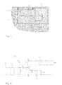
- FIG. 3shows an example of an antenna according to the invention as seen from above, or from the side of the radiating plane.
- the circuit board PCB of a radio deviceis seen below the radiating plane 320 , the conductive upper surface of the circuit board functioning as a ground plane 310 of the antenna.
- the antenna short-circuit conductorjoins the radiating plane at the short-circuit point, or the grounding point G, and the feed conductor joins the radiating plane at the feeding point F.
- a conductor of the antenna adjusting circuitjoins the radiating plane at the adjusting point X.
- the radiating planeis rectangular by outline, and all three points are located at its same long side, the feeding point being located closest to a corner and the grounding point being located therebetween.
- the radiating planeis shaped so that the antenna of the example is a dual-band antenna; it has a lower and an upper operating band.
- the lower operating bandis based on the PIFA structure formed by the radiating plane, the ground plane and the feed and short-circuit conductors.
- the upper operating bandis based on the slot radiator, which slot 322 starts at the edge of the radiating plane, beside the adjusting point X, on the farther side of the point X as seen from the grounding point G.
- the slot 322ends in the inner area of the radiating plane near the opposite end of the plane as seen from the feeding point. The slot naturally affects the electric length of the lower operating band radiator 320 at the same time.
- the radiating planethere is also an L-shaped slot starting between the feeding and short-circuit points, by which slot the antenna matching is improved both in the lower and the upper operating bands.
- the radiating planehas in this example two projections being directed towards the ground plane to tune the antenna and to improve its matching.
- One projection 328is located at the end on the side of the feeding point, and the other projection 329 is located at the side of the grounding and adjusting points, from the open end of the slot radiator 322 towards the opposite end of the plane.
- a circuit connected to itaffects both the lower and the upper operating band. If the adjusting point were connected directly to the ground plane, for example, the electric length of the antenna parts corresponding to both the lower and the upper operating band would decrease, in which case both bands would shift upwards.
- the adjusting circuit connected to the adjusting pointis located either below the radiating plane 320 or on the opposite side of the circuit board PCB.
- the electric distance between the grounding point G and the adjusting point Xhas a significant effect on how big the band displacements are when the adjusting circuit is controlled.
- said distanceis one variable in addition to the variables of the adjusting circuit when a desired result is seeked.
- An arrangementis included in the radiating plane for setting said distance. At the simplest, this arrangement means only that the direct distance between the points G and X is chosen to be suitable. In the example of FIG. 3 the arrangement comprises a notch 326 being located in the portion of the radiating plane between those points.
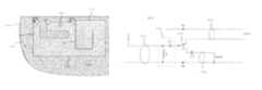
- FIG. 4shows an example of the adjusting circuit of an antenna according to the invention.
- the adjusting circuit 430is galvanically connected to the antenna radiator at the adjusting point X.
- the adjusting circuitcomprises, in order from the radiator, an input line 431 of the adjusting circuit, an LC circuit 432 , a switch 433 and the tuning lines 434 , 435 .
- Each transmission linecomprises a ground conductor and a conductor isolated from the ground, which conductor is also here called a separate conductor.
- the LC circuit 432is on one hand for the ESD protection of the switch and on the other hand for increasing the number of the variable parameters of the adjusting circuit. It is formed of a coil L and a capacitor C 1 .
- the coilhas been connected transversely to the input line 431 , that is between its separate conductor and the ground.
- the capacitor C 1is in series with the separate conductor of the input line, and the second terminal of the capacitor is connected to the common pole of the switch 433 .
- the switchis a two-way switch, where the common pole can be connected to one of two other poles. These other poles are called output poles of the switch.
- the first output pole of the switchis connected to the head end of the separate conductor of the first tuning line 434 , and the second output pole is connected, through the capacitor C 2 , to the head end of the separate conductor of the second tuning line 435 .
- the input line of the adjusting circuitcan continue, after the LC circuit and the switch, either as the first tuning line or as the second tuning line.
- the switch stateis changed, the reactive impedance, which is “seen” from the adjusting point X of the radiating plane to the ground, changes. In that case the resonance frequencies of the antenna parts change and the operating bands therefore shift.
- the first tuning line 434is open at its tail end, and the second tuning line 435 is short-circuited at its tail end.
- the tuning linesare short, usually shorter than the quarter wavelength.
- the open linerepresents a certain capacitance
- the short-circuited linerepresents a certain inductance.
- the values of the capacitance and the inductancedepend on the frequency: At the frequencies of the upper operating band they are higher than at the frequencies of the lower operating band, if the line is shorter than the quarter wavelength also in the upper band. The frequency-dependency of the capacitance in the discrete capacitor is just negligible. So the lengths of the tuning lines are used as variables in this invention when the adjusting circuit is designed.
- the values of the discrete components of the adjusting circuit, the length of the input line 431 and the electric distance between the grounding point G and the adjusting point X in the radiating plane, mentioned in the description of FIG. 3are other variables, or variable parameters
- the starting pointis the dimensioning of the antenna basic structure for part of the radiating plane.
- the number of the variablesis high considering the simplicity of the adjusting circuit, and some variables have different frequency characteristics than some others.
- the capacitor C 2functions also as a blocking capacitor preventing the forming of a direct current circuit through the short-circuited tuning line as seen from the control circuit of the switch. On the side of the open tuning line, no blocking capacitor is needed, of course, but also there could be a discrete component for the tuning purpose.
- the number of the switch operating states and of the tuning lines or circuits corresponding to those statescan naturally be also more than two to implement several alternative places for an operating band.
- more than two operating bandsmay be implemented by the radiating plane, in which case the displacements of them all can be controlled by one adjusting circuit to some extent.
- FIG. 5shows an example of the displacement of operation bands of an antenna according to the invention.
- the examplerelates to the antenna according to FIG. 3 comprising an adjusting circuit according to FIG. 4 .
- the objecthas been that in one switch state the antenna's lower operating band would cover the frequency range 890-960 MHz of the GSM900 system and the upper operating band would cover the frequency range 1710-1880 MHz of the GSM1800 system, and that in the other switch state the lower operating band would cover the frequency range 824-894 MHz of the GSM850 system and the upper operating band would cover the frequency range 1850-1990 MHz of the GSM1900 system.
- Curve 51shows fluctuation of the reflection coefficient as a function of frequency, when the radiator is connected to the short-circuited, very short tuning line.
- Curve 52shows fluctuation of the reflection coefficient, when the radiator is connected to the tuning line, which is open at its tail end. From the curves can be seen that the above-mentioned object is fulfilled for part of the lower operating band, if the value ⁇ 5 dB is considered as a criterion for the usable reflection coefficient. The object is fulfilled also for the upper operating band except for its uppermost part, where the antenna matching is only passable.
- the first tuning line 434is a 3 mm long planar line on the surface of circuit board material FR-4.
- the length of the second tuning line as well as the length of the input line 431 of the adjusting circuitis practically zero. In that case, when the radiator is connected to the short-circuited tuning line, the whole adjusting circuit is “seen” from the radiator as a very short short-circuited transmission line at the frequencies of the lower operating band. This means a low impedance.
- the adjusting circuitwould represent a short-circuited transmission line with about a 1 ⁇ 8 wavelength, but a value has been searched for the capacitance C 2 , which shortens the electric length of the transmission line to zero.
- the capacitance C 2has only a minor effect. Because the upper operating band is located at about double frequencies compared with the lower band, the adjusting circuit is “seen” from the radiator as a short-circuited transmission line with about a quarter wavelength at the frequencies of the upper operating band. This means a high impedance.
- the adjusting circuitis designed so that when the radiator is connected to the open tuning line, the whole adjusting circuit is “seen” from the radiator as a very short open transmission line at the frequencies of the lower operating band.
- the adjusting circuitwould represent an open transmission line with about a 1 ⁇ 8 wavelength, but a value has been searched for the inductance L, which shortens the electric length of the transmission line to zero.
- the inductance Lhas only a minor effect.
- the adjusting circuitis “seen” from the radiator as an open transmission line with about a quarter wavelength at the frequencies of the upper operating band. This means a low impedance.
- the adjusting circuitwould be “seen” as an open transmission line with about a quarter wavelength at the frequencies of the lower operating band, and correspondingly as an open transmission line with about a half wavelength at the frequencies of the upper operating band.
- the whole adjusting circuitwhen the radiator is connected to the short-circuited tuning line, the whole adjusting circuit would be “seen” as a short-circuited transmission line with about a quarter wavelength at the frequencies of the lower operating band, and correspondingly as a short-circuited transmission line with about a half wavelength at the frequencies of the upper operating band.
- the impedance of the adjusting circuitwould change from low to high in the lower operating band and from high to low in the upper operating band, when the switch state is changed. This again results in that the lower operating band shifts down-wards and the upper operating band shifts upwards, as in the previous case corresponding to the exemplary design.
- the physical lengths of the transmission lines neededare considerably shorter, for which reason the adjusting circuit fits into a smaller space.
- FIG. 6shows as a Smith diagram an example of changes in the impedance of the adjusting circuit of an antenna according to the invention.
- the examplerelates to the same structure as the matching curves in FIG. 5 .
- Curve 61shows fluctuation of the impedance as a function of frequency, when the radiator is connected to the short-circuited, very short tuning line
- curve 62shows fluctuation of the impedance, when the radiator is connected to the tuning line, which is open at its tail end.
- the curveswould travel along the outer circle of the diagram. Now they travel only relatively close to the outer circle, which means losses of a certain level in the adjusting circuit. These losses are included in the efficiency curves of FIG. 7 .
- the left end of the curve 61represents the band used by GSM900 system and the right end represents the band used by GSM1800 system.
- the adjusting circuit impedanceis intended to be low, in which case particularly the resistive part of the impedance should be low.
- the resistive partis indeed only about 5% of the antenna characteristics impedance.
- the adjusting circuit impedanceis intended to be high. In this example it is inductive and has an absolute value, which is about five times the antenna characteristics impedance.
- the left end of the curve 62represents the band used by GSM1900 system and the right end represents the band used by GSM850 system.
- the adjusting circuit impedanceis intended to be low, in which case particularly the resistive part of the impedance should be low.
- the resistive partis indeed less than 10% of the antenna characteristics impedance.
- the adjusting circuit impedanceis intended to be high. In this example it is inductive and has an absolute value, which is nearly three times the antenna characteristics impedance.
- FIG. 7shows an example of the efficiency of an antenna according to the invention.
- the exampleconcerns the same structure as the matching curves in FIG. 5 .
- Curve 71shows the fluctuation of the efficiency as a function of frequency when the radiator is connected to the short-circuited, very short tuning line.
- Curve 72shows fluctuation of the efficiency when the radiator is connected to the tuning line, which is open at its tail end. It can be seen from the curves that the efficiency is better than 0.4 in the lower operating bands and better than 0.5 in the upper operating bands except for the very uppermost parts.
- FIG. 8shows another example of the adjusting circuit of an antenna according to the invention.
- the adjusting circuit 830is galvanically connected to the antenna radiator at the adjusting point X.
- the adjusting circuitcomprises, in order from the radiator, an input line 831 of the adjusting circuit, an LC circuit 832 , a switch 833 and the tuning lines 834 , 835 , as in the circuit of FIG. 4 .
- the first output pole of the switchis connected to the head end of the separate conductor of the first tuning line 834
- the second output polehas been connected, through the capacitor C 2 , to the head end of the separate conductor of the second tuning line 835 .
- the first tuning line 834is open at its tail end.
- the differences in respect of the circuit of FIG. 4are: The tuning lines are now of equal length, the second tuning line is now terminated by a coil L 2 , and the capacitor C 2 functions only as a blocking capacitor.
- the antenna proper and the adjusting circuitare designed so that when the radiator is connected to the open tuning line, the antenna's upper operating band covers e.g. the frequency range of the GSM1800 system and the lower operating band covers e.g. the frequency range of the GSM850 system.
- the adjusting circuit impedanceis arranged to be relatively high.
- the inductance of the coil L 2is chosen so that its reactance in the upper operating band is relatively high. For this reason the adjusting circuit impedance hardly changes at the frequencies of the upper operating band when the radiator is connected to the tuning line, which is terminated by the coil L 2 . In that case the upper operating band remains nearly in its place. Instead, at the frequencies of the lower operating band the adjusting circuit impedance becomes lower so that the lower operating band shifts upwards for example to the range used by the GSM900 system.
- Another way to limit the effect of the switch to one operating bandis to implement the LC circuit between the radiator and the switch as a filter, the cut-off frequency of which is located between the lower and upper operating bands of the antenna.
- the filterWhen the object is to displace only the upper operating band, the filter is of high-pass type, and when the object is to displace only the lower operating band, the filter is of low-pass type.
- the order of the filteris naturally selectable.
- this kind of filterfunctions at the same time as an ESD protector for the switch. For this aim a high-pass part can be added to the low-pass filter so that a bandpass filter is formed.
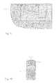
- FIG. 9shows another example of an antenna according to the invention as seen from above, or from the side of the radiating plane.
- the antennais similar to the antenna presented in FIG. 3 .
- the antenna in FIG. 9further comprises a parasitic radiator 950 .
- Thisis located beside the end of the radiating plane 920 on the side of the feeding point F, and is connected to the ground plane at the grounding point G 2 next to the feeding point F.
- Changing the resonance frequencies of the main radiatorhardly affects the resonance frequency of the parasitic element because of its location.
- the resonance frequency of the parasitic elementcan be arranged e.g. into the range of 2.2 GHz so that an operating band is obtained for the antenna in the frequency range used by the WCDMA system (Wideband Code Division Multiple Access).
- the antenna in FIG. 9lacks ground plane on a relatively large area 901 below the radiating plane. This feature has nothing to do with the above-mentioned parasitic radiator: An antenna according to the invention does not require a “solid” ground plane below the radiating plane. The ground plane can be located even considerably more aside from the radiating plane than in the example of FIG. 9 .
- FIG. 10shows a radio device RD, which comprises an adjustable multiband antenna A 00 according to the invention with its adjusting circuit A 30 .
- the adjustable multiband antenna according to the inventionhas been described above. Its structure can naturally differ from that presented.
- the inventiondoes not limit the manufacturing method of the antenna.
- the antennacan be e.g. ceramic, in which case the radiators are conductive coatings of the ceramics.
- the switch used in the adjusting circuitcan be of e.g. the FET (Field Effect Transistor), PHEMT (Pseudomorphic High Electron Mobility Transistor) or MEMS (Micro Electro Mechanical System) type. It is possible to use a capacitance diode as the adjusting component, too.
- the inventive ideacan be applied in different ways within the scope defined by the independent claim 1 .
Landscapes
- Engineering & Computer Science (AREA)
- Computer Networks & Wireless Communication (AREA)
- Waveguide Aerials (AREA)
- Variable-Direction Aerials And Aerial Arrays (AREA)
- Transceivers (AREA)
Abstract
Description
Claims (39)
Priority Applications (1)
| Application Number | Priority Date | Filing Date | Title |
|---|---|---|---|
| US14/877,393US9685698B2 (en) | 2006-07-13 | 2015-10-07 | Multi-tap frequency switchable antenna apparatus, systems and methods |
Applications Claiming Priority (3)
| Application Number | Priority Date | Filing Date | Title |
|---|---|---|---|
| FI20055420AFI20055420A0 (en) | 2005-07-25 | 2005-07-25 | Adjustable multi-band antenna |
| FI20055420 | 2005-07-25 | ||
| PCT/FI2006/050341WO2007012697A1 (en) | 2005-07-25 | 2006-07-13 | Adjustable multiband antenna |
Publications (2)
| Publication Number | Publication Date |
|---|---|
| US20100295737A1 US20100295737A1 (en) | 2010-11-25 |
| US8564485B2true US8564485B2 (en) | 2013-10-22 |
Family
ID=34803286
Family Applications (1)
| Application Number | Title | Priority Date | Filing Date |
|---|---|---|---|
| US11/989,451Active - Reinstated2028-11-29US8564485B2 (en) | 2005-07-25 | 2006-07-13 | Adjustable multiband antenna and methods |
Country Status (6)
| Country | Link |
|---|---|
| US (1) | US8564485B2 (en) |
| EP (1) | EP1908146B1 (en) |
| KR (1) | KR100992919B1 (en) |
| CN (1) | CN101233651B (en) |
| FI (1) | FI20055420A0 (en) |
| WO (1) | WO2007012697A1 (en) |
Cited By (67)
| Publication number | Priority date | Publication date | Assignee | Title |
|---|---|---|---|---|
| US20120119955A1 (en)* | 2008-02-28 | 2012-05-17 | Zlatoljub Milosavljevic | Adjustable multiband antenna and methods |
| US8866689B2 (en) | 2011-07-07 | 2014-10-21 | Pulse Finland Oy | Multi-band antenna and methods for long term evolution wireless system |
| US8988296B2 (en) | 2012-04-04 | 2015-03-24 | Pulse Finland Oy | Compact polarized antenna and methods |
| US9123990B2 (en) | 2011-10-07 | 2015-09-01 | Pulse Finland Oy | Multi-feed antenna apparatus and methods |
| US9203154B2 (en) | 2011-01-25 | 2015-12-01 | Pulse Finland Oy | Multi-resonance antenna, antenna module, radio device and methods |
| US20160020518A1 (en)* | 2007-08-20 | 2016-01-21 | Ethertronics, Inc. | Superimposed multimode antenna for enhanced system filtering |
| US9246210B2 (en) | 2010-02-18 | 2016-01-26 | Pulse Finland Oy | Antenna with cover radiator and methods |
| US9350081B2 (en) | 2014-01-14 | 2016-05-24 | Pulse Finland Oy | Switchable multi-radiator high band antenna apparatus |
| US9461371B2 (en) | 2009-11-27 | 2016-10-04 | Pulse Finland Oy | MIMO antenna and methods |
| US9484619B2 (en) | 2011-12-21 | 2016-11-01 | Pulse Finland Oy | Switchable diversity antenna apparatus and methods |
| US9531058B2 (en) | 2011-12-20 | 2016-12-27 | Pulse Finland Oy | Loosely-coupled radio antenna apparatus and methods |
| US9590308B2 (en) | 2013-12-03 | 2017-03-07 | Pulse Electronics, Inc. | Reduced surface area antenna apparatus and mobile communications devices incorporating the same |
| US9634383B2 (en) | 2013-06-26 | 2017-04-25 | Pulse Finland Oy | Galvanically separated non-interacting antenna sector apparatus and methods |
| US9647338B2 (en) | 2013-03-11 | 2017-05-09 | Pulse Finland Oy | Coupled antenna structure and methods |
| US9673507B2 (en) | 2011-02-11 | 2017-06-06 | Pulse Finland Oy | Chassis-excited antenna apparatus and methods |
| US9680212B2 (en) | 2013-11-20 | 2017-06-13 | Pulse Finland Oy | Capacitive grounding methods and apparatus for mobile devices |
| US9685698B2 (en) | 2006-07-13 | 2017-06-20 | Pulse Finland Oy | Multi-tap frequency switchable antenna apparatus, systems and methods |
| US9722308B2 (en) | 2014-08-28 | 2017-08-01 | Pulse Finland Oy | Low passive intermodulation distributed antenna system for multiple-input multiple-output systems and methods of use |
| US9761951B2 (en) | 2009-11-03 | 2017-09-12 | Pulse Finland Oy | Adjustable antenna apparatus and methods |
| US9906260B2 (en) | 2015-07-30 | 2018-02-27 | Pulse Finland Oy | Sensor-based closed loop antenna swapping apparatus and methods |
| US9917346B2 (en) | 2011-02-11 | 2018-03-13 | Pulse Finland Oy | Chassis-excited antenna apparatus and methods |
| US9948002B2 (en) | 2014-08-26 | 2018-04-17 | Pulse Finland Oy | Antenna apparatus with an integrated proximity sensor and methods |
| US9973228B2 (en) | 2014-08-26 | 2018-05-15 | Pulse Finland Oy | Antenna apparatus with an integrated proximity sensor and methods |
| US9979078B2 (en) | 2012-10-25 | 2018-05-22 | Pulse Finland Oy | Modular cell antenna apparatus and methods |
| US10069209B2 (en) | 2012-11-06 | 2018-09-04 | Pulse Finland Oy | Capacitively coupled antenna apparatus and methods |
| US10069479B1 (en) | 2013-12-31 | 2018-09-04 | Ethertronics, Inc. | Tunable filter for RF circuits |
| US10079428B2 (en) | 2013-03-11 | 2018-09-18 | Pulse Finland Oy | Coupled antenna structure and methods |
| US10396837B2 (en) | 2015-11-13 | 2019-08-27 | Samsung Electronics Co., Ltd | Electronic device including antenna |
| WO2020005961A1 (en)* | 2018-06-25 | 2020-01-02 | Energous Corporation | Power wave transmission techniques to focus wirelessly delivered power at a receiving device |
| US10594165B2 (en) | 2015-11-02 | 2020-03-17 | Energous Corporation | Stamped three-dimensional antenna |
| US10680331B2 (en) | 2015-05-11 | 2020-06-09 | Carrier Corporation | Antenna with reversing current elements |
| US10840743B2 (en) | 2016-12-12 | 2020-11-17 | Energous Corporation | Circuit for managing wireless power transmitting devices |
| US10848853B2 (en) | 2017-06-23 | 2020-11-24 | Energous Corporation | Systems, methods, and devices for utilizing a wire of a sound-producing device as an antenna for receipt of wirelessly delivered power |
| US10923954B2 (en) | 2016-11-03 | 2021-02-16 | Energous Corporation | Wireless power receiver with a synchronous rectifier |
| US10965164B2 (en) | 2012-07-06 | 2021-03-30 | Energous Corporation | Systems and methods of wirelessly delivering power to a receiver device |
| US10985617B1 (en) | 2019-12-31 | 2021-04-20 | Energous Corporation | System for wirelessly transmitting energy at a near-field distance without using beam-forming control |
| US10992185B2 (en) | 2012-07-06 | 2021-04-27 | Energous Corporation | Systems and methods of using electromagnetic waves to wirelessly deliver power to game controllers |
| US10992187B2 (en) | 2012-07-06 | 2021-04-27 | Energous Corporation | System and methods of using electromagnetic waves to wirelessly deliver power to electronic devices |
| US11011942B2 (en) | 2017-03-30 | 2021-05-18 | Energous Corporation | Flat antennas having two or more resonant frequencies for use in wireless power transmission systems |
| US11018779B2 (en) | 2019-02-06 | 2021-05-25 | Energous Corporation | Systems and methods of estimating optimal phases to use for individual antennas in an antenna array |
| US11056929B2 (en) | 2015-09-16 | 2021-07-06 | Energous Corporation | Systems and methods of object detection in wireless power charging systems |
| US11063476B2 (en) | 2017-01-24 | 2021-07-13 | Energous Corporation | Microstrip antennas for wireless power transmitters |
| US11139699B2 (en) | 2019-09-20 | 2021-10-05 | Energous Corporation | Classifying and detecting foreign objects using a power amplifier controller integrated circuit in wireless power transmission systems |
| US11245289B2 (en) | 2016-12-12 | 2022-02-08 | Energous Corporation | Circuit for managing wireless power transmitting devices |
| US11342798B2 (en) | 2017-10-30 | 2022-05-24 | Energous Corporation | Systems and methods for managing coexistence of wireless-power signals and data signals operating in a same frequency band |
| US11355966B2 (en) | 2019-12-13 | 2022-06-07 | Energous Corporation | Charging pad with guiding contours to align an electronic device on the charging pad and efficiently transfer near-field radio-frequency energy to the electronic device |
| US11381118B2 (en) | 2019-09-20 | 2022-07-05 | Energous Corporation | Systems and methods for machine learning based foreign object detection for wireless power transmission |
| US11411441B2 (en) | 2019-09-20 | 2022-08-09 | Energous Corporation | Systems and methods of protecting wireless power receivers using multiple rectifiers and establishing in-band communications using multiple rectifiers |
| US11437735B2 (en) | 2018-11-14 | 2022-09-06 | Energous Corporation | Systems for receiving electromagnetic energy using antennas that are minimally affected by the presence of the human body |
| US11462949B2 (en) | 2017-05-16 | 2022-10-04 | Wireless electrical Grid LAN, WiGL Inc | Wireless charging method and system |
| US11502551B2 (en) | 2012-07-06 | 2022-11-15 | Energous Corporation | Wirelessly charging multiple wireless-power receivers using different subsets of an antenna array to focus energy at different locations |
| US11539243B2 (en) | 2019-01-28 | 2022-12-27 | Energous Corporation | Systems and methods for miniaturized antenna for wireless power transmissions |
| US11670970B2 (en) | 2015-09-15 | 2023-06-06 | Energous Corporation | Detection of object location and displacement to cause wireless-power transmission adjustments within a transmission field |
| US11710321B2 (en) | 2015-09-16 | 2023-07-25 | Energous Corporation | Systems and methods of object detection in wireless power charging systems |
| US11722177B2 (en) | 2013-06-03 | 2023-08-08 | Energous Corporation | Wireless power receivers that are externally attachable to electronic devices |
| US11799324B2 (en) | 2020-04-13 | 2023-10-24 | Energous Corporation | Wireless-power transmitting device for creating a uniform near-field charging area |
| US11831361B2 (en) | 2019-09-20 | 2023-11-28 | Energous Corporation | Systems and methods for machine learning based foreign object detection for wireless power transmission |
| US11863001B2 (en) | 2015-12-24 | 2024-01-02 | Energous Corporation | Near-field antenna for wireless power transmission with antenna elements that follow meandering patterns |
| US11916398B2 (en) | 2021-12-29 | 2024-02-27 | Energous Corporation | Small form-factor devices with integrated and modular harvesting receivers, and shelving-mounted wireless-power transmitters for use therewith |
| US12057715B2 (en) | 2012-07-06 | 2024-08-06 | Energous Corporation | Systems and methods of wirelessly delivering power to a wireless-power receiver device in response to a change of orientation of the wireless-power receiver device |
| US12074452B2 (en) | 2017-05-16 | 2024-08-27 | Wireless Electrical Grid Lan, Wigl Inc. | Networked wireless charging system |
| US12074460B2 (en) | 2017-05-16 | 2024-08-27 | Wireless Electrical Grid Lan, Wigl Inc. | Rechargeable wireless power bank and method of using |
| US12142939B2 (en) | 2022-05-13 | 2024-11-12 | Energous Corporation | Integrated wireless-power-transmission platform designed to operate in multiple bands, and multi-band antennas for use therewith |
| US12155231B2 (en) | 2019-04-09 | 2024-11-26 | Energous Corporation | Asymmetric spiral antennas for wireless power transmission and reception |
| US12224599B2 (en) | 2020-08-12 | 2025-02-11 | Energous Corporation | Systems and methods for secure wireless transmission of power using unidirectional communication signals from a wireless-power-receiving device |
| US12306285B2 (en) | 2020-12-01 | 2025-05-20 | Energous Corporation | Systems and methods for using one or more sensors to detect and classify objects in a keep-out zone of a wireless-power transmission field, and antennas with integrated sensor arrangements |
| US12431735B2 (en) | 2019-09-20 | 2025-09-30 | Energous Corporation | Asymmetric spiral antennas with parasitic elements for wireless power transmission |
Families Citing this family (37)
| Publication number | Priority date | Publication date | Assignee | Title |
|---|---|---|---|---|
| US10211538B2 (en) | 2006-12-28 | 2019-02-19 | Pulse Finland Oy | Directional antenna apparatus and methods |
| TWI351786B (en)* | 2007-11-22 | 2011-11-01 | Arcadyan Technology Corp | Dual band antenna |
| EP2081253A1 (en)* | 2008-01-18 | 2009-07-22 | Laird Technologies AB | Antenna device and portable radio communication device comprising such an antenna device |
| GB2474594B (en)* | 2008-06-06 | 2012-09-26 | Murata Manufacturing Co | Multiband antenna and mounting structure for multiband antenna |
| US20100214184A1 (en)* | 2009-02-24 | 2010-08-26 | Qualcomm Incorporated | Antenna devices and systems for multi-band coverage in a compact volume |
| KR20110030113A (en) | 2009-09-17 | 2011-03-23 | 삼성전자주식회사 | Apparatus and method for adjusting a multiband antenna and its operating frequency in a wireless communication system |
| FI20096101A0 (en)* | 2009-10-27 | 2009-10-27 | Pulse Finland Oy | Procedure and arrangement for fitting an antenna |
| US8847833B2 (en) | 2009-12-29 | 2014-09-30 | Pulse Finland Oy | Loop resonator apparatus and methods for enhanced field control |
| US9406998B2 (en) | 2010-04-21 | 2016-08-02 | Pulse Finland Oy | Distributed multiband antenna and methods |
| KR101687632B1 (en)* | 2010-05-10 | 2016-12-20 | 삼성전자주식회사 | Re-configurable built-in antenna for portable terminal |
| US8354967B2 (en)* | 2010-05-11 | 2013-01-15 | Sony Ericsson Mobile Communications Ab | Antenna array with capacitive coupled upper and lower antenna elements and a peak radiation pattern directed toward the lower antenna element |
| KR101217468B1 (en)* | 2010-11-03 | 2013-01-02 | 주식회사 네오펄스 | Inverted F Antenna With Parastic Coupling Resonance |
| US9166279B2 (en) | 2011-03-07 | 2015-10-20 | Apple Inc. | Tunable antenna system with receiver diversity |
| US9246221B2 (en) | 2011-03-07 | 2016-01-26 | Apple Inc. | Tunable loop antennas |
| US9024823B2 (en)* | 2011-05-27 | 2015-05-05 | Apple Inc. | Dynamically adjustable antenna supporting multiple antenna modes |
| US9450291B2 (en) | 2011-07-25 | 2016-09-20 | Pulse Finland Oy | Multiband slot loop antenna apparatus and methods |
| US9350069B2 (en) | 2012-01-04 | 2016-05-24 | Apple Inc. | Antenna with switchable inductor low-band tuning |
| US9190712B2 (en) | 2012-02-03 | 2015-11-17 | Apple Inc. | Tunable antenna system |
| US8798554B2 (en) | 2012-02-08 | 2014-08-05 | Apple Inc. | Tunable antenna system with multiple feeds |
| US9559433B2 (en) | 2013-03-18 | 2017-01-31 | Apple Inc. | Antenna system having two antennas and three ports |
| US9331397B2 (en) | 2013-03-18 | 2016-05-03 | Apple Inc. | Tunable antenna with slot-based parasitic element |
| US9444130B2 (en) | 2013-04-10 | 2016-09-13 | Apple Inc. | Antenna system with return path tuning and loop element |
| US20150002350A1 (en)* | 2013-07-01 | 2015-01-01 | Sony Corporation | Wireless electronic devices including a variable tuning component |
| CN104681928A (en)* | 2013-11-30 | 2015-06-03 | 深圳富泰宏精密工业有限公司 | Multi-frequency antenna structure |
| US9543660B2 (en)* | 2014-10-09 | 2017-01-10 | Apple Inc. | Electronic device cavity antennas with slots and monopoles |
| CN105633581B (en)* | 2014-11-06 | 2020-06-19 | 深圳富泰宏精密工业有限公司 | Multi-frequency antenna and wireless communication device with same |
| US9728957B2 (en)* | 2015-05-04 | 2017-08-08 | Globalfoundries Singapore Pte. Ltd. | One quarter wavelength transmission line based electrostatic discharge (ESD) protection for integrated circuits |
| CN105576378B (en)* | 2015-12-17 | 2018-11-13 | 京信通信系统(广州)有限公司 | A kind of dual-band antenna, dual polarization dual-band antenna and isolation element preparation method |
| KR102429230B1 (en)* | 2016-02-20 | 2022-08-05 | 삼성전자주식회사 | Antenna and electronic device including the antenna |
| KR102393808B1 (en)* | 2017-06-20 | 2022-05-04 | 삼성전자주식회사 | An electronic device comprising antenna |
| US10804617B2 (en)* | 2017-09-11 | 2020-10-13 | Apple Inc. | Electronic devices having shared antenna structures and split return paths |
| WO2022046028A1 (en)* | 2020-08-25 | 2022-03-03 | Hewlett-Packard Development Company, L.P. | Multi-band antennas |
| CN114221123B (en)* | 2021-12-16 | 2025-02-14 | 惠州Tcl移动通信有限公司 | Antenna device and mobile terminal |
| TWI807673B (en)* | 2022-03-08 | 2023-07-01 | 啟碁科技股份有限公司 | Electronic device and antenna structure |
| TWI844221B (en)* | 2023-01-05 | 2024-06-01 | 啟碁科技股份有限公司 | Antenna structure and mobile device having the same |
| EP4614726A1 (en)* | 2024-03-08 | 2025-09-10 | Valeo Comfort and Driving Assistance | Antenna of an electronic device for a vehicle |
| CN118336347B (en)* | 2024-05-17 | 2025-01-24 | 南通大学 | A bandwidth reconfigurable end-fire antenna based on switch-loaded coupled dipole |
Citations (463)
| Publication number | Priority date | Publication date | Assignee | Title |
|---|---|---|---|---|
| GB239246A (en) | 1924-04-14 | 1926-02-26 | Walter Zipper | Improvements in rims with removable flanges for automobile vehicles and the like |
| US2745102A (en) | 1945-12-14 | 1956-05-08 | Norgorden Oscar | Antenna |
| US3938161A (en) | 1974-10-03 | 1976-02-10 | Ball Brothers Research Corporation | Microstrip antenna structure |
| US4004228A (en) | 1974-04-29 | 1977-01-18 | Integrated Electronics, Ltd. | Portable transmitter |
| US4028652A (en) | 1974-09-06 | 1977-06-07 | Murata Manufacturing Co., Ltd. | Dielectric resonator and microwave filter using the same |
| US4031468A (en) | 1976-05-04 | 1977-06-21 | Reach Electronics, Inc. | Receiver mount |
| US4054874A (en) | 1975-06-11 | 1977-10-18 | Hughes Aircraft Company | Microstrip-dipole antenna elements and arrays thereof |
| US4069483A (en) | 1976-11-10 | 1978-01-17 | The United States Of America As Represented By The Secretary Of The Navy | Coupled fed magnetic microstrip dipole antenna |
| US4123758A (en) | 1976-02-27 | 1978-10-31 | Sumitomo Electric Industries, Ltd. | Disc antenna |
| US4123756A (en) | 1976-09-24 | 1978-10-31 | Nippon Electric Co., Ltd. | Built-in miniature radio antenna |
| US4131893A (en) | 1977-04-01 | 1978-12-26 | Ball Corporation | Microstrip radiator with folded resonant cavity |
| US4201960A (en) | 1978-05-24 | 1980-05-06 | Motorola, Inc. | Method for automatically matching a radio frequency transmitter to an antenna |
| US4255729A (en) | 1978-05-13 | 1981-03-10 | Oki Electric Industry Co., Ltd. | High frequency filter |
| US4313121A (en) | 1980-03-13 | 1982-01-26 | The United States Of America As Represented By The Secretary Of The Army | Compact monopole antenna with structured top load |
| US4356492A (en) | 1981-01-26 | 1982-10-26 | The United States Of America As Represented By The Secretary Of The Navy | Multi-band single-feed microstrip antenna system |
| US4370657A (en) | 1981-03-09 | 1983-01-25 | The United States Of America As Represented By The Secretary Of The Navy | Electrically end coupled parasitic microstrip antennas |
| US4423396A (en) | 1980-09-30 | 1983-12-27 | Matsushita Electric Industrial Company, Limited | Bandpass filter for UHF band |
| US4431977A (en) | 1982-02-16 | 1984-02-14 | Motorola, Inc. | Ceramic bandpass filter |
| US4546357A (en) | 1983-04-11 | 1985-10-08 | The Singer Company | Furniture antenna system |
| US4559508A (en) | 1983-02-10 | 1985-12-17 | Murata Manufacturing Co., Ltd. | Distribution constant filter with suppression of TE11 resonance mode |
| FR2553584B1 (en) | 1983-10-13 | 1986-04-04 | Applic Rech Electronique | HALF-LOOP ANTENNA FOR LAND VEHICLE |
| US4625212A (en) | 1983-03-19 | 1986-11-25 | Nec Corporation | Double loop antenna for use in connection to a miniature radio receiver |
| EP0208424A1 (en) | 1985-06-11 | 1987-01-14 | Matsushita Electric Industrial Co., Ltd. | Dielectric filter with a quarter wavelength coaxial resonator |
| US4652889A (en) | 1983-12-13 | 1987-03-24 | Thomson-Csf | Plane periodic antenna |
| US4661992A (en) | 1985-07-31 | 1987-04-28 | Motorola Inc. | Switchless external antenna connector for portable radios |
| US4692726A (en) | 1986-07-25 | 1987-09-08 | Motorola, Inc. | Multiple resonator dielectric filter |
| US4703291A (en) | 1985-03-13 | 1987-10-27 | Murata Manufacturing Co., Ltd. | Dielectric filter for use in a microwave integrated circuit |
| US4706050A (en) | 1984-09-22 | 1987-11-10 | Smiths Industries Public Limited Company | Microstrip devices |
| US4716391A (en) | 1986-07-25 | 1987-12-29 | Motorola, Inc. | Multiple resonator component-mountable filter |
| US4740765A (en) | 1985-09-30 | 1988-04-26 | Murata Manufacturing Co., Ltd. | Dielectric filter |
| US4742562A (en) | 1984-09-27 | 1988-05-03 | Motorola, Inc. | Single-block dual-passband ceramic filter useable with a transceiver |
| US4761624A (en) | 1986-08-08 | 1988-08-02 | Alps Electric Co., Ltd. | Microwave band-pass filter |
| US4800348A (en) | 1987-08-03 | 1989-01-24 | Motorola, Inc. | Adjustable electronic filter and method of tuning same |
| US4800392A (en) | 1987-01-08 | 1989-01-24 | Motorola, Inc. | Integral laminar antenna and radio housing |
| US4821006A (en) | 1987-01-17 | 1989-04-11 | Murata Manufacturing Co., Ltd. | Dielectric resonator apparatus |
| US4823098A (en) | 1988-06-14 | 1989-04-18 | Motorola, Inc. | Monolithic ceramic filter with bandstop function |
| US4827266A (en) | 1985-02-26 | 1989-05-02 | Mitsubishi Denki Kabushiki Kaisha | Antenna with lumped reactive matching elements between radiator and groundplate |
| US4862181A (en) | 1986-10-31 | 1989-08-29 | Motorola, Inc. | Miniature integral antenna-radio apparatus |
| US4879533A (en) | 1988-04-01 | 1989-11-07 | Motorola, Inc. | Surface mount filter with integral transmission line connection |
| US4896124A (en) | 1988-10-31 | 1990-01-23 | Motorola, Inc. | Ceramic filter having integral phase shifting network |
| EP0376643A2 (en) | 1988-12-27 | 1990-07-04 | Harada Industry Co., Ltd. | Flat-plate antenna for use in mobile communications |
| US4954796A (en) | 1986-07-25 | 1990-09-04 | Motorola, Inc. | Multiple resonator dielectric filter |
| US4965537A (en) | 1988-06-06 | 1990-10-23 | Motorola Inc. | Tuneless monolithic ceramic filter manufactured by using an art-work mask process |
| US4977383A (en) | 1988-10-27 | 1990-12-11 | Lk-Products Oy | Resonator structure |
| US4980694A (en) | 1989-04-14 | 1990-12-25 | Goldstar Products Company, Limited | Portable communication apparatus with folded-slot edge-congruent antenna |
| EP0339822A3 (en) | 1988-04-25 | 1991-01-02 | Gec Ferranti Defence Systems Limited | Transceiver testing apparatus |
| US5017932A (en) | 1988-11-04 | 1991-05-21 | Kokusai Electric Co., Ltd. | Miniature antenna |
| US5047739A (en) | 1987-11-20 | 1991-09-10 | Lk-Products Oy | Transmission line resonator |
| US5053786A (en) | 1982-01-28 | 1991-10-01 | General Instrument Corporation | Broadband directional antenna |
| US5097236A (en) | 1989-05-02 | 1992-03-17 | Murata Manufacturing Co., Ltd. | Parallel connection multi-stage band-pass filter |
| US5103197A (en) | 1989-06-09 | 1992-04-07 | Lk-Products Oy | Ceramic band-pass filter |
| US5109536A (en) | 1989-10-27 | 1992-04-28 | Motorola, Inc. | Single-block filter for antenna duplexing and antenna-summed diversity |
| US5155493A (en) | 1990-08-28 | 1992-10-13 | The United States Of America As Represented By The Secretary Of The Air Force | Tape type microstrip patch antenna |
| US5157363A (en) | 1990-02-07 | 1992-10-20 | Lk Products | Helical resonator filter with adjustable couplings |
| US5159303A (en) | 1990-05-04 | 1992-10-27 | Lk-Products | Temperature compensation in a helix resonator |
| US5166697A (en) | 1991-01-28 | 1992-11-24 | Lockheed Corporation | Complementary bowtie dipole-slot antenna |
| US5170173A (en) | 1992-04-27 | 1992-12-08 | Motorola, Inc. | Antenna coupling apparatus for cordless telephone |
| US5203021A (en) | 1990-10-22 | 1993-04-13 | Motorola Inc. | Transportable support assembly for transceiver |
| US5210542A (en) | 1991-07-03 | 1993-05-11 | Ball Corporation | Microstrip patch antenna structure |
| US5210510A (en) | 1990-02-07 | 1993-05-11 | Lk-Products Oy | Tunable helical resonator |
| US5220335A (en) | 1990-03-30 | 1993-06-15 | The United States Of America As Represented By The Administrator Of The National Aeronautics And Space Administration | Planar microstrip Yagi antenna array |
| US5229777A (en) | 1991-11-04 | 1993-07-20 | Doyle David W | Microstrap antenna |
| EP0279050B1 (en) | 1987-01-15 | 1993-08-04 | Ball Corporation | Three resonator parasitically coupled microstrip antenna array element |
| US5239279A (en) | 1991-04-12 | 1993-08-24 | Lk-Products Oy | Ceramic duplex filter |
| EP0278069B1 (en) | 1986-12-29 | 1993-08-25 | Ball Corporation | Near-isotropic low profile microstrip radiator especially suited for use as a mobile vehicle antenna |
| EP0332139B1 (en) | 1988-03-10 | 1993-09-15 | Kabushiki Kaisha Toyota Chuo Kenkyusho | Wide band antenna for mobile communications |
| GB2266997A (en) | 1992-05-07 | 1993-11-17 | Wallen Manufacturing Limited | Radio antenna. |
| US5278528A (en) | 1991-04-12 | 1994-01-11 | Lk-Products Oy | Air insulated high frequency filter with resonating rods |
| EP0400872B1 (en) | 1989-05-23 | 1994-01-19 | Harada Industry Co., Ltd. | A flat-plate antenna for use in mobile communications |
| US5281326A (en) | 1990-09-19 | 1994-01-25 | Lk-Products Oy | Method for coating a dielectric ceramic piece |
| US5298873A (en) | 1991-06-25 | 1994-03-29 | Lk-Products Oy | Adjustable resonator arrangement |
| US5302924A (en) | 1991-06-25 | 1994-04-12 | Lk-Products Oy | Temperature compensated dielectric filter |
| US5304968A (en) | 1991-10-31 | 1994-04-19 | Lk-Products Oy | Temperature compensated resonator |
| US5307036A (en) | 1989-06-09 | 1994-04-26 | Lk-Products Oy | Ceramic band-stop filter |
| US5319328A (en) | 1991-06-25 | 1994-06-07 | Lk-Products Oy | Dielectric filter |
| US5349315A (en) | 1991-06-25 | 1994-09-20 | Lk-Products Oy | Dielectric filter |
| US5349700A (en) | 1991-10-28 | 1994-09-20 | Bose Corporation | Antenna tuning system for operation over a predetermined frequency range |
| US5351023A (en) | 1992-04-21 | 1994-09-27 | Lk-Products Oy | Helix resonator |
| US5354463A (en) | 1991-06-25 | 1994-10-11 | Lk Products Oy | Dielectric filter |
| US5355142A (en) | 1991-10-15 | 1994-10-11 | Ball Corporation | Microstrip antenna structure suitable for use in mobile radio communications and method for making same |
| US5357262A (en) | 1991-12-10 | 1994-10-18 | Blaese Herbert R | Auxiliary antenna connector |
| US5363114A (en) | 1990-01-29 | 1994-11-08 | Shoemaker Kevin O | Planar serpentine antennas |
| US5369782A (en) | 1990-08-22 | 1994-11-29 | Mitsubishi Denki Kabushiki Kaisha | Radio relay system, including interference signal cancellation |
| US5382959A (en) | 1991-04-05 | 1995-01-17 | Ball Corporation | Broadband circular polarization antenna |
| US5386214A (en) | 1989-02-14 | 1995-01-31 | Fujitsu Limited | Electronic circuit device |
| US5387886A (en) | 1992-05-14 | 1995-02-07 | Lk-Products Oy | Duplex filter operating as a change-over switch |
| US5394162A (en) | 1993-03-18 | 1995-02-28 | Ford Motor Company | Low-loss RF coupler for testing a cellular telephone |
| US5408206A (en) | 1992-05-08 | 1995-04-18 | Lk-Products Oy | Resonator structure having a strip and groove serving as transmission line resonators |
| US5418508A (en) | 1992-11-23 | 1995-05-23 | Lk-Products Oy | Helix resonator filter |
| US5432489A (en) | 1992-03-09 | 1995-07-11 | Lk-Products Oy | Filter with strip lines |
| US5438697A (en) | 1992-04-23 | 1995-08-01 | M/A-Com, Inc. | Microstrip circuit assembly and components therefor |
| US5440315A (en) | 1994-01-24 | 1995-08-08 | Intermec Corporation | Antenna apparatus for capacitively coupling an antenna ground plane to a moveable antenna |
| US5442366A (en) | 1993-07-13 | 1995-08-15 | Ball Corporation | Raised patch antenna |
| US5442280A (en) | 1992-09-10 | 1995-08-15 | Gec Alstom T & D Sa | Device for measuring an electrical current in a conductor using a Rogowski coil |
| US5444453A (en) | 1993-02-02 | 1995-08-22 | Ball Corporation | Microstrip antenna structure having an air gap and method of constructing same |
| EP0399975B1 (en) | 1989-05-22 | 1995-11-02 | Nokia Mobile Phones Ltd. | RF connector for the connection of a radiotelephone to an external antenna |
| US5467065A (en) | 1993-03-03 | 1995-11-14 | Lk-Products Oy | Filter having resonators coupled by a saw filter and a duplex filter formed therefrom |
| US5473295A (en) | 1990-07-06 | 1995-12-05 | Lk-Products Oy | Saw notch filter for improving stop-band attenuation of a duplex filter |
| US5506554A (en) | 1993-07-02 | 1996-04-09 | Lk-Products Oy | Dielectric filter with inductive coupling electrodes formed on an adjacent insulating layer |
| US5508668A (en) | 1993-04-08 | 1996-04-16 | Lk-Products Oy | Helix resonator filter with a coupling aperture extending from a side wall |
| EP0447218B1 (en) | 1990-03-15 | 1996-05-08 | Hughes Aircraft Company | Plural frequency patch antenna assembly |
| US5517683A (en) | 1995-01-18 | 1996-05-14 | Cycomm Corporation | Conformant compact portable cellular phone case system and connector |
| US5521561A (en) | 1994-02-09 | 1996-05-28 | Lk Products Oy | Arrangement for separating transmission and reception |
| US5532703A (en) | 1993-04-22 | 1996-07-02 | Valor Enterprises, Inc. | Antenna coupler for portable cellular telephones |
| US5541560A (en) | 1993-03-03 | 1996-07-30 | Lk-Products Oy | Selectable bandstop/bandpass filter with switches selecting the resonator coupling |
| US5541617A (en) | 1991-10-21 | 1996-07-30 | Connolly; Peter J. | Monolithic quadrifilar helix antenna |
| US5543764A (en) | 1993-03-03 | 1996-08-06 | Lk-Products Oy | Filter having an electromagnetically tunable transmission zero |
| US5550519A (en) | 1994-01-18 | 1996-08-27 | Lk-Products Oy | Dielectric resonator having a frequency tuning element extending into the resonator hole |
| US5557287A (en) | 1995-03-06 | 1996-09-17 | Motorola, Inc. | Self-latching antenna field coupler |
| US5557292A (en) | 1994-06-22 | 1996-09-17 | Space Systems/Loral, Inc. | Multiple band folding antenna |
| EP0615285A3 (en) | 1993-03-11 | 1996-09-18 | Csir | Mounting an electronic circuit on a substrate. |
| US5570071A (en) | 1990-05-04 | 1996-10-29 | Lk-Products Oy | Supporting of a helix resonator |
| US5585771A (en) | 1993-12-23 | 1996-12-17 | Lk-Products Oy | Helical resonator filter including short circuit stub tuning |
| US5585810A (en) | 1994-05-05 | 1996-12-17 | Murata Manufacturing Co., Ltd. | Antenna unit |
| US5589844A (en) | 1995-06-06 | 1996-12-31 | Flash Comm, Inc. | Automatic antenna tuner for low-cost mobile radio |
| US5594395A (en) | 1993-09-10 | 1997-01-14 | Lk-Products Oy | Diode tuned resonator filter |
| US5604471A (en) | 1994-03-15 | 1997-02-18 | Lk Products Oy | Resonator device including U-shaped coupling support element |
| EP0759646A1 (en) | 1995-08-07 | 1997-02-26 | Murata Manufacturing Co., Ltd. | Chip antenna |
| US5627502A (en) | 1994-01-26 | 1997-05-06 | Lk Products Oy | Resonator filter with variable tuning |
| US5649316A (en) | 1995-03-17 | 1997-07-15 | Elden, Inc. | In-vehicle antenna |
| US5668561A (en) | 1995-11-13 | 1997-09-16 | Motorola, Inc. | Antenna coupler |
| US5675301A (en) | 1994-05-26 | 1997-10-07 | Lk Products Oy | Dielectric filter having resonators aligned to effect zeros of the frequency response |
| US5689221A (en) | 1994-10-07 | 1997-11-18 | Lk Products Oy | Radio frequency filter comprising helix resonators |
| US5694135A (en) | 1995-12-18 | 1997-12-02 | Motorola, Inc. | Molded patch antenna having an embedded connector and method therefor |
| US5703600A (en) | 1996-05-08 | 1997-12-30 | Motorola, Inc. | Microstrip antenna with a parasitically coupled ground plane |
| US5709832A (en) | 1995-06-02 | 1998-01-20 | Ericsson Inc. | Method of manufacturing a printed antenna |
| US5711014A (en) | 1993-04-05 | 1998-01-20 | Crowley; Robert J. | Antenna transmission coupling arrangement |
| US5717368A (en) | 1993-09-10 | 1998-02-10 | Lk-Products Oy | Varactor tuned helical resonator for use with duplex filter |
| US5731749A (en) | 1995-05-03 | 1998-03-24 | Lk-Products Oy | Transmission line resonator filter with variable slot coupling and link coupling #10 |
| EP0831547A2 (en) | 1996-09-20 | 1998-03-25 | Murata Manufacturing Co., Ltd. | Microstrip antenna |
| US5734350A (en) | 1996-04-08 | 1998-03-31 | Xertex Technologies, Inc. | Microstrip wide band antenna |
| US5734305A (en) | 1995-03-22 | 1998-03-31 | Lk-Products Oy | Stepwise switched filter |
| US5734351A (en) | 1995-06-05 | 1998-03-31 | Lk-Products Oy | Double-action antenna |
| EP0637094B1 (en) | 1993-07-30 | 1998-04-08 | Matsushita Electric Industrial Co., Ltd. | Antenna for mobile communication |
| US5739735A (en) | 1995-03-22 | 1998-04-14 | Lk Products Oy | Filter with improved stop/pass ratio |
| US5742259A (en) | 1995-04-07 | 1998-04-21 | Lk-Products Oy | Resilient antenna structure and a method to manufacture it |
| US5757327A (en) | 1994-07-29 | 1998-05-26 | Mitsumi Electric Co., Ltd. | Antenna unit for use in navigation system |
| US5764190A (en) | 1996-07-15 | 1998-06-09 | The Hong Kong University Of Science & Technology | Capacitively loaded PIFA |
| US5768217A (en) | 1996-05-14 | 1998-06-16 | Casio Computer Co., Ltd. | Antennas and their making methods and electronic devices or timepieces with the antennas |
| US5767809A (en) | 1996-03-07 | 1998-06-16 | Industrial Technology Research Institute | OMNI-directional horizontally polarized Alford loop strip antenna |
| US5777585A (en) | 1995-04-08 | 1998-07-07 | Sony Corporation | Antenna coupling apparatus, external-antenna connecting apparatus, and onboard external-antenna connecting apparatus |
| US5777581A (en) | 1995-12-07 | 1998-07-07 | Atlantic Aerospace Electronics Corporation | Tunable microstrip patch antennas |
| EP0856907A1 (en) | 1997-02-04 | 1998-08-05 | Lucent Technologies Inc. | Aperture-coupled planar inverted-F antenna |
| US5793269A (en) | 1995-08-23 | 1998-08-11 | Lk-Products Oy | Stepwise regulated filter having a multiple-step switch |
| US5812094A (en) | 1996-04-02 | 1998-09-22 | Qualcomm Incorporated | Antenna coupler for a portable radiotelephone |
| US5815048A (en) | 1995-11-23 | 1998-09-29 | Lk-Products Oy | Switchable duplex filter |
| US5822705A (en) | 1995-09-26 | 1998-10-13 | Nokia Mobile Phones, Ltd. | Apparatus for connecting a radiotelephone to an external antenna |
| US5852421A (en) | 1996-04-02 | 1998-12-22 | Qualcomm Incorporated | Dual-band antenna coupler for a portable radiotelephone |
| US5861854A (en) | 1996-06-19 | 1999-01-19 | Murata Mfg. Co. Ltd. | Surface-mount antenna and a communication apparatus using the same |
| EP0751043B1 (en) | 1995-06-30 | 1999-01-20 | Nokia Mobile Phones Ltd. | Rack |
| US5874926A (en) | 1996-03-11 | 1999-02-23 | Murata Mfg Co. Ltd | Matching circuit and antenna apparatus |
| US5880697A (en) | 1996-09-25 | 1999-03-09 | Torrey Science Corporation | Low-profile multi-band antenna |
| US5886668A (en) | 1994-03-08 | 1999-03-23 | Hagenuk Telecom Gmbh | Hand-held transmitting and/or receiving apparatus |
| EP0766341B1 (en) | 1995-09-29 | 1999-03-31 | Murata Manufacturing Co., Ltd. | Surface mounting antenna and communication apparatus using the same antenna |
| US5892490A (en) | 1996-11-07 | 1999-04-06 | Murata Manufacturing Co., Ltd. | Meander line antenna |
| US5903820A (en) | 1995-04-07 | 1999-05-11 | Lk-Products Oy | Radio communications transceiver with integrated filter, antenna switch, directional coupler and active components |
| US5905475A (en) | 1995-04-05 | 1999-05-18 | Lk Products Oy | Antenna, particularly a mobile phone antenna, and a method to manufacture the antenna |
| US5920290A (en) | 1994-03-04 | 1999-07-06 | Flexcon Company Inc. | Resonant tag labels and method of making the same |
| US5926139A (en) | 1997-07-02 | 1999-07-20 | Lucent Technologies Inc. | Planar dual frequency band antenna |
| US5929813A (en) | 1998-01-09 | 1999-07-27 | Nokia Mobile Phones Limited | Antenna for mobile communications device |
| US5936583A (en) | 1992-09-30 | 1999-08-10 | Kabushiki Kaisha Toshiba | Portable radio communication device with wide bandwidth and improved antenna radiation efficiency |
| US5943016A (en) | 1995-12-07 | 1999-08-24 | Atlantic Aerospace Electronics, Corp. | Tunable microstrip patch antenna and feed network therefor |
| EP0942488A2 (en) | 1998-02-24 | 1999-09-15 | Murata Manufacturing Co., Ltd. | Antenna device and radio device comprising the same |
| US5959583A (en) | 1995-12-27 | 1999-09-28 | Qualcomm Incorporated | Antenna adapter |
| US5963180A (en) | 1996-03-29 | 1999-10-05 | Symmetricom, Inc. | Antenna system for radio signals in at least two spaced-apart frequency bands |
| US5966097A (en) | 1996-06-03 | 1999-10-12 | Mitsubishi Denki Kabushiki Kaisha | Antenna apparatus |
| US5970393A (en) | 1997-02-25 | 1999-10-19 | Polytechnic University | Integrated micro-strip antenna apparatus and a system utilizing the same for wireless communications for sensing and actuation purposes |
| US5977710A (en) | 1996-03-11 | 1999-11-02 | Nec Corporation | Patch antenna and method for making the same |
| US5986606A (en) | 1996-08-21 | 1999-11-16 | France Telecom | Planar printed-circuit antenna with short-circuited superimposed elements |
| US5986608A (en) | 1998-04-02 | 1999-11-16 | Lucent Technologies Inc. | Antenna coupler for portable telephone |
| US5990848A (en) | 1996-02-16 | 1999-11-23 | Lk-Products Oy | Combined structure of a helical antenna and a dielectric plate |
| US5999132A (en) | 1996-10-02 | 1999-12-07 | Northern Telecom Limited | Multi-resonant antenna |
| US6005529A (en) | 1996-12-04 | 1999-12-21 | Ico Services Ltd. | Antenna assembly with relocatable antenna for mobile transceiver |
| US6006419A (en) | 1998-09-01 | 1999-12-28 | Millitech Corporation | Synthetic resin transreflector and method of making same |
| US6008764A (en) | 1997-03-25 | 1999-12-28 | Nokia Mobile Phones Limited | Broadband antenna realized with shorted microstrips |
| US6009311A (en) | 1996-02-21 | 1999-12-28 | Etymotic Research | Method and apparatus for reducing audio interference from cellular telephone transmissions |
| EP0621653B1 (en) | 1993-04-23 | 1999-12-29 | Murata Manufacturing Co., Ltd. | Surface-mountable antenna unit |
| US6014106A (en) | 1996-11-14 | 2000-01-11 | Lk-Products Oy | Simple antenna structure |
| US6016130A (en) | 1996-08-22 | 2000-01-18 | Lk-Products Oy | Dual-frequency antenna |
| US6023608A (en) | 1996-04-26 | 2000-02-08 | Lk-Products Oy | Integrated filter construction |
| US6031496A (en) | 1996-08-06 | 2000-02-29 | Ik-Products Oy | Combination antenna |
| US6034637A (en) | 1997-12-23 | 2000-03-07 | Motorola, Inc. | Double resonant wideband patch antenna and method of forming same |
| US6034640A (en)* | 1997-04-01 | 2000-03-07 | Murata Manufacturing Co., Ltd. | Antenna device |
| US6037848A (en) | 1996-09-26 | 2000-03-14 | Lk-Products Oy | Electrically regulated filter having a selectable stop band |
| US6043780A (en) | 1995-12-27 | 2000-03-28 | Funk; Thomas J. | Antenna adapter |
| EP0999807A1 (en) | 1997-08-01 | 2000-05-17 | Corneal Industrie | Flexible single-piece intraocular implant |
| EP1003240A2 (en) | 1998-11-17 | 2000-05-24 | Murata Manufacturing Co., Ltd. | Surface mount antenna and communication apparatus using the same |
| EP1006606A1 (en) | 1996-07-05 | 2000-06-07 | Robert Bosch Gmbh | A holder and a method for transferring signals between apparatus and holder |
| US6078231A (en) | 1997-02-07 | 2000-06-20 | Lk-Products Oy | High frequency filter with a dielectric board element to provide electromagnetic couplings |
| EP1014487A1 (en) | 1998-12-23 | 2000-06-28 | Sony International (Europe) GmbH | Patch antenna and method for tuning a patch antenna |
| US6091363A (en) | 1995-03-23 | 2000-07-18 | Honda Giken Kogyo Kabushiki Kaisha | Radar module and antenna device |
| EP0851530A3 (en) | 1996-12-28 | 2000-07-26 | Lucent Technologies Inc. | Antenna apparatus in wireless terminals |
| US6097345A (en) | 1998-11-03 | 2000-08-01 | The Ohio State University | Dual band antenna for vehicles |
| EP1024553A1 (en) | 1999-01-26 | 2000-08-02 | Société Anonyme SYLEA | Electrical connector for flat cable |
| EP1026774A3 (en) | 1999-01-26 | 2000-08-30 | Siemens Aktiengesellschaft | Antenna for wireless operated communication terminals |
| JP2000278028A (en) | 1999-03-26 | 2000-10-06 | Murata Mfg Co Ltd | Chip antenna, antenna system and radio unit |
| US6133879A (en) | 1997-12-11 | 2000-10-17 | Alcatel | Multifrequency microstrip antenna and a device including said antenna |
| US6134421A (en) | 1997-09-10 | 2000-10-17 | Qualcomm Incorporated | RF coupler for wireless telephone cradle |
| US6140973A (en) | 1997-01-24 | 2000-10-31 | Lk-Products Oy | Simple dual-frequency antenna |
| EP1052723A2 (en) | 1999-05-10 | 2000-11-15 | Nokia Mobile Phones Ltd. | Antenna construction |
| EP0749214A3 (en) | 1995-06-15 | 2000-11-22 | Murata Manufacturing Co., Ltd. | Radio communication equipment |
| DE10015583A1 (en) | 1999-03-30 | 2000-11-23 | Ngk Insulators Ltd | Internal radio transceiver antenna, for mobile telephone, has separate transmit/receive antennas on one dielectric block mounted on circuit board |
| US6157819A (en) | 1996-05-14 | 2000-12-05 | Lk-Products Oy | Coupling element for realizing electromagnetic coupling and apparatus for coupling a radio telephone to an external antenna |
| EP1063722A2 (en) | 1999-06-25 | 2000-12-27 | Murata Manufacturing Co., Ltd. | Antenna device and communication apparatus using the same |
| US6177908B1 (en) | 1998-04-28 | 2001-01-23 | Murata Manufacturing Co., Ltd. | Surface-mounting type antenna, antenna device, and communication device including the antenna device |
| US6185434B1 (en) | 1996-09-11 | 2001-02-06 | Lk-Products Oy | Antenna filtering arrangement for a dual mode radio communication device |
| US6190942B1 (en) | 1996-10-09 | 2001-02-20 | Pav Card Gmbh | Method and connection arrangement for producing a smart card |
| US6195049B1 (en) | 1998-09-11 | 2001-02-27 | Samsung Electronics Co., Ltd. | Micro-strip patch antenna for transceiver |
| US6204826B1 (en) | 1999-07-22 | 2001-03-20 | Ericsson Inc. | Flat dual frequency band antennas for wireless communicators |
| US6215376B1 (en) | 1998-05-08 | 2001-04-10 | Lk-Products Oy | Filter construction and oscillator for frequencies of several gigahertz |
| US6252552B1 (en) | 1999-01-05 | 2001-06-26 | Filtronic Lk Oy | Planar dual-frequency antenna and radio apparatus employing a planar antenna |
| US6252554B1 (en) | 1999-06-14 | 2001-06-26 | Lk-Products Oy | Antenna structure |
| US6255994B1 (en) | 1998-09-30 | 2001-07-03 | Nec Corporation | Inverted-F antenna and radio communication system equipped therewith |
| EP1113524A2 (en) | 1999-12-30 | 2001-07-04 | Nokia Mobile Phones Ltd. | Antenna structure, method for coupling a signal to the antenna structure, antenna unit and mobile station with such an antenna structure |
| US6259029B1 (en) | 1998-03-27 | 2001-07-10 | Hawke Cable Glands Limited | Cable gland |
| US6268831B1 (en) | 2000-04-04 | 2001-07-31 | Ericsson Inc. | Inverted-f antennas with multiple planar radiating elements and wireless communicators incorporating same |
| JP2001217631A (en) | 2000-02-04 | 2001-08-10 | Murata Mfg Co Ltd | Surface-mounted antenna and its adjusting method, and communication device equipped with surface-mounted type antenna |
| KR20010080521A (en) | 1999-09-30 | 2001-08-22 | 무라타 야스타카 | surface-mount antenna and communication device with surface-mount antenna |
| EP1128466A2 (en) | 2000-02-24 | 2001-08-29 | Filtronic LK Oy | Planar antenna structure |
| GB2360422A (en) | 2000-03-15 | 2001-09-19 | Texas Instruments Ltd | Identifying transponders on difficult to read items |
| JP2001267833A (en) | 2000-03-16 | 2001-09-28 | Mitsubishi Electric Corp | Microstrip antenna |
| US6304220B1 (en) | 1999-08-05 | 2001-10-16 | Alcatel | Antenna with stacked resonant structures and a multi-frequency radiocommunications system including it |
| US6308720B1 (en) | 1998-04-08 | 2001-10-30 | Lockheed Martin Corporation | Method for precision-cleaning propellant tanks |
| EP0807988B1 (en) | 1996-05-14 | 2001-11-07 | Filtronic LK Oy | Coupling element for a radio telephone antenna |
| US6316975B1 (en) | 1996-05-13 | 2001-11-13 | Micron Technology, Inc. | Radio frequency data communications device |
| JP2001326513A (en) | 2000-05-15 | 2001-11-22 | Sharp Corp | Mobile phone |
| US6326921B1 (en) | 2000-03-14 | 2001-12-04 | Telefonaktiebolaget Lm Ericsson (Publ) | Low profile built-in multi-band antenna |
| EP0766340B1 (en) | 1995-09-28 | 2001-12-12 | Murata Manufacturing Co., Ltd. | Surface mounting antenna and communication apparatus using the same antenna |
| US20010050636A1 (en) | 1999-01-26 | 2001-12-13 | Martin Weinberger | Antenna for radio-operated communication terminal equipment |
| US6337663B1 (en) | 2001-01-02 | 2002-01-08 | Auden Techno Corp. | Built-in dual frequency antenna |
| US6340954B1 (en) | 1997-12-16 | 2002-01-22 | Filtronic Lk Oy | Dual-frequency helix antenna |
| US6342859B1 (en) | 1998-04-20 | 2002-01-29 | Allgon Ab | Ground extension arrangement for coupling to ground means in an antenna system, and an antenna system and a mobile radio device having such ground arrangement |
| WO2002011236A1 (en) | 2000-08-01 | 2002-02-07 | Sagem Sa | Planar radiating surface antenna and portable telephone comprising same |
| US6346914B1 (en) | 1999-08-25 | 2002-02-12 | Filtronic Lk Oy | Planar antenna structure |
| US6348892B1 (en) | 1999-10-20 | 2002-02-19 | Filtronic Lk Oy | Internal antenna for an apparatus |
| US6353443B1 (en) | 1998-07-09 | 2002-03-05 | Telefonaktiebolaget Lm Ericsson (Publ) | Miniature printed spiral antenna for mobile terminals |
| EP1052722A3 (en) | 1999-05-11 | 2002-03-20 | Nokia Corporation | Antenna |
| US6366243B1 (en) | 1998-10-30 | 2002-04-02 | Filtronic Lk Oy | Planar antenna with two resonating frequencies |
| US6377827B1 (en) | 1998-09-25 | 2002-04-23 | Ericsson Inc. | Mobile telephone having a folding antenna |
| US6380905B1 (en) | 1999-09-10 | 2002-04-30 | Filtronic Lk Oy | Planar antenna structure |
| FI20020829A0 (en) | 2002-05-02 | 2002-05-02 | Filtronic Lk Oy | Plane antenna feed arrangement |
| SE511900E (en) | 1998-04-01 | 2002-05-21 | Allgon Ab | Antenna device, a method for its preparation and a handheld radio communication device |
| US6396444B1 (en) | 1998-12-23 | 2002-05-28 | Nokia Mobile Phones Limited | Antenna and method of production |
| US6404394B1 (en) | 1999-12-23 | 2002-06-11 | Tyco Electronics Logistics Ag | Dual polarization slot antenna assembly |
| US6417813B1 (en) | 2000-10-31 | 2002-07-09 | Harris Corporation | Feedthrough lens antenna and associated methods |
| US6423915B1 (en) | 2001-07-26 | 2002-07-23 | Centurion Wireless Technologies, Inc. | Switch contact for a planar inverted F antenna |
| US6429818B1 (en) | 1998-01-16 | 2002-08-06 | Tyco Electronics Logistics Ag | Single or dual band parasitic antenna assembly |
| DE10104862A1 (en) | 2001-02-03 | 2002-08-08 | Bosch Gmbh Robert | Junction conductor for connecting circuit board track to separate circuit section e.g. patch of patch antenna, comprises pins on arm which are inserted into holes on circuit board |
| US6452558B1 (en) | 2000-08-23 | 2002-09-17 | Matsushita Electric Industrial Co., Ltd. | Antenna apparatus and a portable wireless communication apparatus |
| US6452551B1 (en) | 2001-08-02 | 2002-09-17 | Auden Techno Corp. | Capacitor-loaded type single-pole planar antenna |
| US6456249B1 (en) | 1999-08-16 | 2002-09-24 | Tyco Electronics Logistics A.G. | Single or dual band parasitic antenna assembly |
| US6459413B1 (en) | 2001-01-10 | 2002-10-01 | Industrial Technology Research Institute | Multi-frequency band antenna |
| US6462716B1 (en) | 2000-08-24 | 2002-10-08 | Murata Manufacturing Co., Ltd. | Antenna device and radio equipment having the same |
| US6469673B2 (en) | 2000-06-30 | 2002-10-22 | Nokia Mobile Phones Ltd. | Antenna circuit arrangement and testing method |
| US6473056B2 (en) | 2000-06-12 | 2002-10-29 | Filtronic Lk Oy | Multiband antenna |
| JP2002319811A (en) | 2001-04-19 | 2002-10-31 | Murata Mfg Co Ltd | Plural resonance antenna |
| US6476769B1 (en) | 2001-09-19 | 2002-11-05 | Nokia Corporation | Internal multi-band antenna |
| US6480155B1 (en) | 1999-12-28 | 2002-11-12 | Nokia Corporation | Antenna assembly, and associated method, having an active antenna element and counter antenna element |
| JP2002329541A (en) | 2001-05-01 | 2002-11-15 | Kojima Press Co Ltd | Contact for antenna signal |
| JP2002335117A (en) | 2001-05-08 | 2002-11-22 | Murata Mfg Co Ltd | Antenna structure and communication device equipped therewith |
| US20020183013A1 (en) | 2001-05-25 | 2002-12-05 | Auckland David T. | Programmable radio frequency sub-system with integrated antennas and filters and wireless communication device using same |
| US20020196192A1 (en) | 2001-06-20 | 2002-12-26 | Murata Manufacturing Co., Ltd. | Surface mount type antenna and radio transmitter and receiver using the same |
| KR20020096016A (en) | 2001-06-15 | 2002-12-28 | 히타치 긴조쿠 가부시키가이샤 | Surface-mounted antenna and communications apparatus comprising same |
| US6501425B1 (en) | 1999-09-09 | 2002-12-31 | Murrata Manufacturing Co., Ltd. | Surface-mounted type antenna and communication device including the same |
| US6518925B1 (en) | 1999-07-08 | 2003-02-11 | Filtronic Lk Oy | Multifrequency antenna |
| US6529168B2 (en) | 2000-10-27 | 2003-03-04 | Filtronic Lk Oy | Double-action antenna |
| US6535170B2 (en) | 2000-12-11 | 2003-03-18 | Sony Corporation | Dual band built-in antenna device and mobile wireless terminal equipped therewith |
| EP1294048A2 (en) | 2001-09-13 | 2003-03-19 | Kabushiki Kaisha Toshiba | Information device incorporating an integrated antenna for wireless communication |
| EP1294049A1 (en) | 2001-09-14 | 2003-03-19 | Nokia Corporation | Internal multi-band antenna with improved radiation efficiency |
| US6538604B1 (en) | 1999-11-01 | 2003-03-25 | Filtronic Lk Oy | Planar antenna |
| US6549167B1 (en) | 2001-09-25 | 2003-04-15 | Samsung Electro-Mechanics Co., Ltd. | Patch antenna for generating circular polarization |
| DE10150149A1 (en) | 2001-10-11 | 2003-04-17 | Receptec Gmbh | Antenna module for automobile mobile radio antenna has antenna element spaced above conductive base plate and coupled to latter via short-circuit path |
| US6556812B1 (en) | 1998-11-04 | 2003-04-29 | Nokia Mobile Phones Limited | Antenna coupler and arrangement for coupling a radio telecommunication device to external apparatuses |
| EP1306922A2 (en) | 2001-10-24 | 2003-05-02 | Matsushita Electric Industrial Co., Ltd. | Antenna structure, methof of using antenna structure and communication device |
| US6566944B1 (en) | 2002-02-21 | 2003-05-20 | Ericsson Inc. | Current modulator with dynamic amplifier impedance compensation |
| US6580396B2 (en) | 2001-05-25 | 2003-06-17 | Chi Mei Communication Systems, Inc. | Dual-band antenna with three resonators |
| US6580397B2 (en) | 2000-10-27 | 2003-06-17 | Telefonaktiebolaget L M Ericsson (Publ) | Arrangement for a mobile terminal |
| JP2003179426A (en) | 2001-12-13 | 2003-06-27 | Matsushita Electric Ind Co Ltd | Antenna device and portable wireless device |
| US6600449B2 (en) | 2001-04-10 | 2003-07-29 | Murata Manufacturing Co., Ltd. | Antenna apparatus |
| US6603430B1 (en) | 2000-03-09 | 2003-08-05 | Tyco Electronics Logistics Ag | Handheld wireless communication devices with antenna having parasitic element |
| US6606016B2 (en) | 2000-03-10 | 2003-08-12 | Murata Manufacturing Co., Ltd. | Surface acoustic wave device using two parallel connected filters with different passbands |
| US6611235B2 (en) | 2001-03-07 | 2003-08-26 | Smarteq Wireless Ab | Antenna coupling device |
| US6614400B2 (en) | 2000-08-07 | 2003-09-02 | Telefonaktiebolaget Lm Ericsson (Publ) | Antenna |
| US6614405B1 (en) | 1997-11-25 | 2003-09-02 | Filtronic Lk Oy | Frame structure |
| US6634564B2 (en) | 2000-10-24 | 2003-10-21 | Dai Nippon Printing Co., Ltd. | Contact/noncontact type data carrier module |
| US6636181B2 (en) | 2000-12-26 | 2003-10-21 | International Business Machines Corporation | Transmitter, computer system, and opening/closing structure |
| US6639564B2 (en) | 2002-02-13 | 2003-10-28 | Gregory F. Johnson | Device and method of use for reducing hearing aid RF interference |
| JP2003318638A (en) | 2002-04-05 | 2003-11-07 | Hewlett Packard Co <Hp> | Capacity feeding built-in multi-band antenna |
| US6646606B2 (en) | 2000-10-18 | 2003-11-11 | Filtronic Lk Oy | Double-action antenna |
| US6650295B2 (en)* | 2002-01-28 | 2003-11-18 | Nokia Corporation | Tunable antenna for wireless communication terminals |
| US6657595B1 (en) | 2002-05-09 | 2003-12-02 | Motorola, Inc. | Sensor-driven adaptive counterpoise antenna system |
| US6670926B2 (en) | 2001-10-31 | 2003-12-30 | Kabushiki Kaisha Toshiba | Wireless communication device and information-processing apparatus which can hold the device |
| US6677903B2 (en) | 2000-12-04 | 2004-01-13 | Arima Optoelectronics Corp. | Mobile communication device having multiple frequency band antenna |
| US6683573B2 (en) | 2002-04-16 | 2004-01-27 | Samsung Electro-Mechanics Co., Ltd. | Multi band chip antenna with dual feeding ports, and mobile communication apparatus using the same |
| US6693594B2 (en) | 2001-04-02 | 2004-02-17 | Nokia Corporation | Optimal use of an electrically tunable multiband planar antenna |
| US6717551B1 (en) | 2002-11-12 | 2004-04-06 | Ethertronics, Inc. | Low-profile, multi-frequency, multi-band, magnetic dipole antenna |
| JP2004112028A (en) | 2002-09-13 | 2004-04-08 | Hitachi Metals Ltd | Antenna device and communication apparatus using the same |
| US6727857B2 (en) | 2001-05-17 | 2004-04-27 | Filtronic Lk Oy | Multiband antenna |
| EP1329980A4 (en) | 2000-09-26 | 2004-04-28 | Matsushita Electric Industrial Co Ltd | PORTABLE RADIO DEVICE ANTENNA |
| US6734826B1 (en) | 2002-11-08 | 2004-05-11 | Hon Hai Precisionind. Co., Ltd. | Multi-band antenna |
| US6734825B1 (en) | 2002-10-28 | 2004-05-11 | The National University Of Singapore | Miniature built-in multiple frequency band antenna |
| US20040090378A1 (en) | 2002-11-08 | 2004-05-13 | Hsin Kuo Dai | Multi-band antenna structure |
| US6738022B2 (en) | 2001-04-18 | 2004-05-18 | Filtronic Lk Oy | Method for tuning an antenna and an antenna |
| US6741214B1 (en) | 2002-11-06 | 2004-05-25 | Centurion Wireless Technologies, Inc. | Planar Inverted-F-Antenna (PIFA) having a slotted radiating element providing global cellular and GPS-bluetooth frequency response |
| EP0923158B1 (en) | 1997-12-10 | 2004-06-02 | Nokia Corporation | Antenna |
| US6753813B2 (en) | 2001-07-25 | 2004-06-22 | Murata Manufacturing Co., Ltd. | Surface mount antenna, method of manufacturing the surface mount antenna, and radio communication apparatus equipped with the surface mount antenna |
| EP1432072A1 (en) | 2002-12-16 | 2004-06-23 | Filtronic LK Oy | Antenna for flat radio device |
| US6759989B2 (en) | 2001-10-22 | 2004-07-06 | Filtronic Lk Oy | Internal multiband antenna |
| EP1437793A1 (en) | 2002-12-31 | 2004-07-14 | Filtronic LK Oy | Antenna for foldable radio device |
| US6765536B2 (en) | 2002-05-09 | 2004-07-20 | Motorola, Inc. | Antenna with variably tuned parasitic element |
| EP1439603A1 (en) | 2003-01-15 | 2004-07-21 | Filtronic LK Oy | Antenna element as part of the cover of a radio device |
| US20040145525A1 (en) | 2001-06-01 | 2004-07-29 | Ayoub Annabi | Plate antenna |
| US6774853B2 (en) | 2002-11-07 | 2004-08-10 | Accton Technology Corporation | Dual-band planar monopole antenna with a U-shaped slot |
| US6781545B2 (en) | 2002-05-31 | 2004-08-24 | Samsung Electro-Mechanics Co., Ltd. | Broadband chip antenna |
| US20040171403A1 (en) | 2001-06-29 | 2004-09-02 | Filtronic Lk Oy | Integrated radio telephone structure |
| US6801166B2 (en) | 2002-02-01 | 2004-10-05 | Filtronic Lx Oy | Planar antenna |
| US6801169B1 (en) | 2003-03-14 | 2004-10-05 | Hon Hai Precision Ind. Co., Ltd. | Multi-band printed monopole antenna |
| EP1414108A3 (en) | 2002-10-23 | 2004-10-06 | Murata Manufacturing Co., Ltd. | Surface mount antenna, antenna device and communication device using the same |
| EP1220456A3 (en) | 2000-12-29 | 2004-10-20 | Nokia Corporation | Arrangement for antenna matching |
| EP1469549A1 (en) | 2003-04-15 | 2004-10-20 | Filtronic LK Oy | Adjustable multi-band PIFA antenna |
| US6819293B2 (en) | 2001-02-13 | 2004-11-16 | Koninklijke Philips Electronics N.V. | Patch antenna with switchable reactive components for multiple frequency use in mobile communications |
| US6819287B2 (en) | 2002-03-15 | 2004-11-16 | Centurion Wireless Technologies, Inc. | Planar inverted-F antenna including a matching network having transmission line stubs and capacitor/inductor tank circuits |
| WO2004100313A1 (en) | 2003-05-12 | 2004-11-18 | Nokia Corporation | Open-ended slotted pifa antenna and tuning method |
| US6825818B2 (en) | 2001-04-11 | 2004-11-30 | Kyocera Wireless Corp. | Tunable matching circuit |
| EP1482592A1 (en) | 2003-05-29 | 2004-12-01 | Sony Corporation | A surface mount antenna, and an antenna element mounting method |
| EP0892459B1 (en) | 1997-07-08 | 2004-12-15 | Nokia Corporation | Double resonance antenna structure for several frequency ranges |
| JP2004363859A (en) | 2003-06-04 | 2004-12-24 | Hitachi Metals Ltd | Antenna system, and electronic equipment using the same |
| US6836249B2 (en) | 2002-10-22 | 2004-12-28 | Motorola, Inc. | Reconfigurable antenna for multiband operation |
| JP2005005985A (en) | 2003-06-11 | 2005-01-06 | Sony Chem Corp | Antenna element and antenna mounting substrate |
| US6847329B2 (en) | 2002-07-09 | 2005-01-25 | Hitachi Cable, Ltd. | Plate-like multiple antenna and electrical equipment provided therewith |
| EP1453137A4 (en) | 2002-06-25 | 2005-02-02 | Matsushita Electric Industrial Co Ltd | ANTENNA FOR PORTABLE RADIO |
| US6856293B2 (en) | 2001-03-15 | 2005-02-15 | Filtronic Lk Oy | Adjustable antenna |
| US6862441B2 (en) | 2003-06-09 | 2005-03-01 | Nokia Corporation | Transmitter filter arrangement for multiband mobile phone |
| US6862437B1 (en) | 1999-06-03 | 2005-03-01 | Tyco Electronics Corporation | Dual band tuning |
| US20050057401A1 (en) | 2003-09-01 | 2005-03-17 | Alps Electric Co., Ltd. | Small-size, low-height antenna device capable of easily ensuring predetermined bandwidth |
| EP1098387B1 (en) | 1999-05-21 | 2005-03-23 | Matsushita Electric Industrial Co., Ltd. | Mobile communication antenna and mobile communication apparatus using it |
| US6876329B2 (en) | 2002-08-30 | 2005-04-05 | Filtronic Lk Oy | Adjustable planar antenna |
| EP1248316B1 (en) | 2001-04-02 | 2005-04-13 | Murata Manufacturing Co., Ltd. | Antenna and communication apparatus having the same |
| EP1170822B1 (en) | 2000-07-07 | 2005-04-13 | SMARTEQ Wireless AB | Adapter antenna for mobile phones |
| US6882317B2 (en) | 2001-11-27 | 2005-04-19 | Filtronic Lk Oy | Dual antenna and radio device |
| WO2005038981A1 (en) | 2003-10-20 | 2005-04-28 | Lk Products Oy | Internal multiband antenna |
| US6891507B2 (en) | 2002-11-13 | 2005-05-10 | Murata Manufacturing Co., Ltd. | Surface mount antenna, method of manufacturing same, and communication device |
| US6897810B2 (en) | 2002-11-13 | 2005-05-24 | Hon Hai Precision Ind. Co., Ltd | Multi-band antenna |
| US6900768B2 (en) | 2001-09-25 | 2005-05-31 | Matsushita Electric Industrial Co., Ltd. | Antenna device and communication equipment using the device |
| US6903692B2 (en) | 2001-06-01 | 2005-06-07 | Filtronic Lk Oy | Dielectric antenna |
| EP1544943A1 (en) | 2003-12-15 | 2005-06-22 | Filtronic LK Oy | Tunable multiband planar antenna |
| US6911945B2 (en) | 2003-02-27 | 2005-06-28 | Filtronic Lk Oy | Multi-band planar antenna |
| US20050159131A1 (en) | 2004-01-21 | 2005-07-21 | Kabushiki Kaisha Tokai Rika Denki Seisakusho | Communicator and vehicle controller |
| US6925689B2 (en) | 2003-07-15 | 2005-08-09 | Jan Folkmar | Spring clip |
| US6927792B1 (en) | 1999-03-11 | 2005-08-09 | Matsushita Electric Industrial Co., Ltd. | Television camera and white balance correcting method |
| US20050176481A1 (en) | 2004-02-06 | 2005-08-11 | Samsung Electronics Co., Ltd. | Antenna device for portable wireless terminal |
| EP1361623B1 (en) | 2002-05-08 | 2005-08-24 | Sony Ericsson Mobile Communications AB | Multiple frequency bands switchable antenna for portable terminals |
| US6937196B2 (en) | 2003-01-15 | 2005-08-30 | Filtronic Lk Oy | Internal multiband antenna |
| JP2005252661A (en) | 2004-03-04 | 2005-09-15 | Matsushita Electric Ind Co Ltd | Antenna module |
| US6950068B2 (en) | 2001-11-15 | 2005-09-27 | Filtronic Lk Oy | Method of manufacturing an internal antenna, and antenna element |
| US6950066B2 (en) | 2002-08-22 | 2005-09-27 | Skycross, Inc. | Apparatus and method for forming a monolithic surface-mountable antenna |
| US6952144B2 (en) | 2003-06-16 | 2005-10-04 | Intel Corporation | Apparatus and method to provide power amplification |
| US6958730B2 (en) | 2001-05-02 | 2005-10-25 | Murata Manufacturing Co., Ltd. | Antenna device and radio communication equipment including the same |
| US6961544B1 (en) | 1999-07-14 | 2005-11-01 | Filtronic Lk Oy | Structure of a radio-frequency front end |
| US6963310B2 (en) | 2002-09-09 | 2005-11-08 | Hitachi Cable, Ltd. | Mobile phone antenna |
| US6963308B2 (en) | 2003-01-15 | 2005-11-08 | Filtronic Lk Oy | Multiband antenna |
| US6967618B2 (en) | 2002-04-09 | 2005-11-22 | Filtronic Lk Oy | Antenna with variable directional pattern |
| EP1146589B1 (en) | 2000-04-14 | 2005-11-23 | Hitachi Metals, Ltd. | Chip antenna element and communication apparatus comprising the same |
| US6975278B2 (en) | 2003-02-28 | 2005-12-13 | Hong Kong Applied Science and Technology Research Institute, Co., Ltd. | Multiband branch radiator antenna element |
| WO2006000631A1 (en) | 2004-06-28 | 2006-01-05 | Pulse Finland Oy | Chip antenna |
| US6985108B2 (en) | 2002-09-19 | 2006-01-10 | Filtronic Lk Oy | Internal antenna |
| US6992543B2 (en) | 2002-11-22 | 2006-01-31 | Raytheon Company | Mems-tuned high power, high efficiency, wide bandwidth power amplifier |
| US6995710B2 (en) | 2001-10-09 | 2006-02-07 | Ngk Spark Plug Co., Ltd. | Dielectric antenna for high frequency wireless communication apparatus |
| US7023341B2 (en) | 2003-02-03 | 2006-04-04 | Ingrid, Inc. | RFID reader for a security network |
| US20060071857A1 (en) | 2003-02-04 | 2006-04-06 | Heiko Pelzer | Planar high-frequency or microwave antenna |
| US7031744B2 (en) | 2000-12-01 | 2006-04-18 | Nec Corporation | Compact cellular phone |
| EP1406345B1 (en) | 2002-07-18 | 2006-04-26 | BenQ Corporation | PIFA-antenna with additional inductance |
| US7042403B2 (en) | 2004-01-23 | 2006-05-09 | General Motors Corporation | Dual band, low profile omnidirectional antenna |
| WO2006051160A1 (en) | 2004-11-11 | 2006-05-18 | Pulse Finland Oy | Antenna component |
| US7053841B2 (en) | 2003-07-31 | 2006-05-30 | Motorola, Inc. | Parasitic element and PIFA antenna structure |
| US7054671B2 (en) | 2000-09-27 | 2006-05-30 | Nokia Mobile Phones, Ltd. | Antenna arrangement in a mobile station |
| US7057560B2 (en) | 2003-05-07 | 2006-06-06 | Agere Systems Inc. | Dual-band antenna for a wireless local area network device |
| US7081857B2 (en) | 2002-12-02 | 2006-07-25 | Lk Products Oy | Arrangement for connecting additional antenna to radio device |
| US7084831B2 (en) | 2004-02-26 | 2006-08-01 | Matsushita Electric Industrial Co., Ltd. | Wireless device having antenna |
| WO2006084951A1 (en) | 2005-02-08 | 2006-08-17 | Pulse Finland Oy | Internal monopole antenna |
| US7113133B2 (en) | 2004-12-31 | 2006-09-26 | Advanced Connectek Inc. | Dual-band inverted-F antenna with a branch line shorting strip |
| US7119749B2 (en) | 2004-04-28 | 2006-10-10 | Murata Manufacturing Co., Ltd. | Antenna and radio communication apparatus |
| US7126546B2 (en) | 2001-06-29 | 2006-10-24 | Lk Products Oy | Arrangement for integrating a radio phone structure |
| US7136020B2 (en) | 2003-11-12 | 2006-11-14 | Murata Manufacturing Co., Ltd. | Antenna structure and communication device using the same |
| US7142824B2 (en) | 2002-10-07 | 2006-11-28 | Matsushita Electric Industrial Co., Ltd. | Antenna device with a first and second antenna |
| US7148849B2 (en) | 2003-12-23 | 2006-12-12 | Quanta Computer, Inc. | Multi-band antenna |
| US7148851B2 (en) | 2003-08-08 | 2006-12-12 | Hitachi Metals, Ltd. | Antenna device and communications apparatus comprising same |
| US7148847B2 (en) | 2003-09-01 | 2006-12-12 | Alps Electric Co., Ltd. | Small-size, low-height antenna device capable of easily ensuring predetermined bandwidth |
| EP1271690B1 (en) | 2001-06-29 | 2006-12-13 | Nokia Corporation | An antenna |
| WO2007000483A1 (en) | 2005-06-28 | 2007-01-04 | Pulse Finland Oy | Internal multiband antenna |
| US7170464B2 (en) | 2004-09-21 | 2007-01-30 | Industrial Technology Research Institute | Integrated mobile communication antenna |
| US7176838B1 (en) | 2005-08-22 | 2007-02-13 | Motorola, Inc. | Multi-band antenna |
| US7180455B2 (en) | 2004-10-13 | 2007-02-20 | Samsung Electro-Mechanics Co., Ltd. | Broadband internal antenna |
| US20070042615A1 (en) | 2005-08-22 | 2007-02-22 | Hon Hai Precision Ind. Co., Ltd. | Land grid array socket |
| US7193574B2 (en) | 2004-10-18 | 2007-03-20 | Interdigital Technology Corporation | Antenna for controlling a beam direction both in azimuth and elevation |
| US20070082789A1 (en) | 2005-10-07 | 2007-04-12 | Polar Electro Oy | Method, performance monitor and computer program for determining performance |
| US7205942B2 (en) | 2005-07-06 | 2007-04-17 | Nokia Corporation | Multi-band antenna arrangement |
| US7218280B2 (en) | 2004-04-26 | 2007-05-15 | Pulse Finland Oy | Antenna element and a method for manufacturing the same |
| US7218282B2 (en) | 2003-04-28 | 2007-05-15 | Fraunhofer-Gesellschaft Zur Foerderung Der Angewandten Forschung E.V. | Antenna device |
| CN1316797C (en) | 2001-11-09 | 2007-05-16 | 艾利森公司 | Method and apparatus for creating packets using a digital signal processor |
| US7224313B2 (en) | 2003-05-09 | 2007-05-29 | Actiontec Electronics, Inc. | Multiband antenna with parasitically-coupled resonators |
| EP1791213A1 (en) | 2005-11-24 | 2007-05-30 | Pulse Finland Oy | Multiband antenna component |
| US7230574B2 (en) | 2002-02-13 | 2007-06-12 | Greg Johnson | Oriented PIFA-type device and method of use for reducing RF interference |
| US7237318B2 (en) | 2003-03-31 | 2007-07-03 | Pulse Finland Oy | Method for producing antenna components |
| US20070152881A1 (en) | 2005-12-29 | 2007-07-05 | Chan Yiu K | Multi-band antenna system |
| EP1445822B1 (en) | 2003-02-07 | 2007-08-22 | Ngk Spark Plug Co., Ltd | Chip antenna |
| US7274334B2 (en) | 2005-03-24 | 2007-09-25 | Tdk Corporation | Stacked multi-resonator antenna |
| EP1843432A1 (en) | 2005-01-27 | 2007-10-10 | Murata Manufacturing Co., Ltd. | Antenna and wireless communication device |
| US7283097B2 (en) | 2002-11-28 | 2007-10-16 | Research In Motion Limited | Multi-band antenna with patch and slot structures |
| US7289064B2 (en) | 2005-08-23 | 2007-10-30 | Intel Corporation | Compact multi-band, multi-port antenna |
| EP1753079A4 (en) | 2004-05-12 | 2007-10-31 | Yokowo Seisakusho Kk | Multi-band antenna, circuit substrate and communication device |
| US7292200B2 (en) | 2004-09-23 | 2007-11-06 | Mobile Mark, Inc. | Parasitically coupled folded dipole multi-band antenna |
| US7319432B2 (en) | 2002-03-14 | 2008-01-15 | Sony Ericsson Mobile Communications Ab | Multiband planar built-in radio antenna with inverted-L main and parasitic radiators |
| US7330153B2 (en) | 2006-04-10 | 2008-02-12 | Navcom Technology, Inc. | Multi-band inverted-L antenna |
| US7333067B2 (en) | 2004-05-24 | 2008-02-19 | Hon Hai Precision Ind. Co., Ltd. | Multi-band antenna with wide bandwidth |
| US7339528B2 (en) | 2003-12-24 | 2008-03-04 | Nokia Corporation | Antenna for mobile communication terminals |
| US7340286B2 (en) | 2003-10-09 | 2008-03-04 | Lk Products Oy | Cover structure for a radio device |
| US20080055164A1 (en) | 2006-09-05 | 2008-03-06 | Zhijun Zhang | Tunable antennas for handheld devices |
| US20080059106A1 (en) | 2006-09-01 | 2008-03-06 | Wight Alan N | Diagnostic applications for electronic equipment providing embedded and remote operation and reporting |
| FR2873247B1 (en) | 2004-07-15 | 2008-03-07 | Nortel Networks Ltd | RADIO TRANSMITTER WITH VARIABLE IMPEDANCE ADAPTATION |
| US7345634B2 (en) | 2004-08-20 | 2008-03-18 | Kyocera Corporation | Planar inverted “F” antenna and method of tuning same |
| US7352326B2 (en) | 2003-10-31 | 2008-04-01 | Lk Products Oy | Multiband planar antenna |
| US20080088511A1 (en) | 2005-03-16 | 2008-04-17 | Juha Sorvala | Antenna component and methods |
| US7382319B2 (en) | 2003-12-02 | 2008-06-03 | Murata Manufacturing Co., Ltd. | Antenna structure and communication apparatus including the same |
| US7385556B2 (en) | 2006-11-03 | 2008-06-10 | Hon Hai Precision Industry Co., Ltd. | Planar antenna |
| US7388543B2 (en) | 2005-11-15 | 2008-06-17 | Sony Ericsson Mobile Communications Ab | Multi-frequency band antenna device for radio communication terminal having wide high-band bandwidth |
| US7405702B2 (en) | 2003-07-24 | 2008-07-29 | Pulse Finland Oy | Antenna arrangement for connecting an external device to a radio device |
| US7417588B2 (en) | 2004-01-30 | 2008-08-26 | Fractus, S.A. | Multi-band monopole antennas for mobile network communications devices |
| US7423592B2 (en) | 2004-01-30 | 2008-09-09 | Fractus, S.A. | Multi-band monopole antennas for mobile communications devices |
| US7432860B2 (en) | 2006-05-17 | 2008-10-07 | Sony Ericsson Mobile Communications Ab | Multi-band antenna for GSM, UMTS, and WiFi applications |
| US7439929B2 (en) | 2005-12-09 | 2008-10-21 | Sony Ericsson Mobile Communications Ab | Tuning antennas with finite ground plane |
| US20080266199A1 (en) | 2005-10-14 | 2008-10-30 | Zlatoljub Milosavljevic | Adjustable antenna and methods |
| US7468709B2 (en) | 2003-09-11 | 2008-12-23 | Pulse Finland Oy | Method for mounting a radiator in a radio device and a radio device |
| US20090009415A1 (en) | 2006-01-09 | 2009-01-08 | Mika Tanska | RFID antenna and methods |
| US7498990B2 (en) | 2005-07-15 | 2009-03-03 | Samsung Electro-Mechanics Co., Ltd. | Internal antenna having perpendicular arrangement |
| US7502598B2 (en) | 2004-05-28 | 2009-03-10 | Infineon Technologies Ag | Transmitting arrangement, receiving arrangement, transceiver and method for operation of a transmitting arrangement |
| US7501983B2 (en) | 2003-01-15 | 2009-03-10 | Lk Products Oy | Planar antenna structure and radio device |
| EP1067627B1 (en) | 1999-07-09 | 2009-06-24 | IPCom GmbH & Co. KG | Dual band radio apparatus |
| US20090196160A1 (en) | 2005-10-17 | 2009-08-06 | Berend Crombach | Coating for Optical Discs |
| US7589678B2 (en) | 2005-10-03 | 2009-09-15 | Pulse Finland Oy | Multi-band antenna with a common resonant feed structure and methods |
| US7616158B2 (en) | 2006-05-26 | 2009-11-10 | Hong Kong Applied Science And Technology Research Institute Co., Ltd. | Multi mode antenna system |
| US7633449B2 (en) | 2008-02-29 | 2009-12-15 | Motorola, Inc. | Wireless handset with improved hearing aid compatibility |
| US7692543B2 (en) | 2004-11-02 | 2010-04-06 | Sensormatic Electronics, LLC | Antenna for a combination EAS/RFID tag with a detacher |
| US7710325B2 (en) | 2006-08-15 | 2010-05-04 | Intel Corporation | Multi-band dielectric resonator antenna |
| US7724204B2 (en) | 2006-10-02 | 2010-05-25 | Pulse Engineering, Inc. | Connector antenna apparatus and methods |
| US7760146B2 (en) | 2005-03-24 | 2010-07-20 | Nokia Corporation | Internal digital TV antennas for hand-held telecommunications device |
| US7764245B2 (en) | 2006-06-16 | 2010-07-27 | Cingular Wireless Ii, Llc | Multi-band antenna |
| US7786938B2 (en) | 2004-06-28 | 2010-08-31 | Pulse Finland Oy | Antenna, component and methods |
| US7800544B2 (en) | 2003-11-12 | 2010-09-21 | Laird Technologies Ab | Controllable multi-band antenna device and portable radio communication device comprising such an antenna device |
| US20100244978A1 (en) | 2007-04-19 | 2010-09-30 | Zlatoljub Milosavljevic | Methods and apparatus for matching an antenna |
| US7830327B2 (en) | 2007-05-18 | 2010-11-09 | Powerwave Technologies, Inc. | Low cost antenna design for wireless communications |
| US20100309092A1 (en) | 2008-01-29 | 2010-12-09 | Riku Lambacka | Contact spring for planar antenna, antenna and methods |
| US7889139B2 (en) | 2007-06-21 | 2011-02-15 | Apple Inc. | Handheld electronic device with cable grounding |
| US7889143B2 (en) | 2005-10-03 | 2011-02-15 | Pulse Finland Oy | Multiband antenna system and methods |
| US7901617B2 (en) | 2004-05-18 | 2011-03-08 | Auckland Uniservices Limited | Heat exchanger |
| EP1467456B1 (en) | 2003-04-07 | 2011-03-09 | VERDA s.r.l. | Cable-retainer apparatus |
| US20110102290A1 (en) | 2007-08-30 | 2011-05-05 | Zlatoljub Milosavljevic | Adjustable multi-band antenna and methods |
| EP1564839B1 (en) | 2004-02-10 | 2011-06-08 | Hitachi, Ltd. | Semiconductor chip with coil antenna and communication system with such a semiconductor chip |
| US20110133994A1 (en) | 2006-11-15 | 2011-06-09 | Heikki Korva | Internal multi-band antenna and methods |
| US7963347B2 (en) | 2007-10-16 | 2011-06-21 | Schlumberger Technology Corporation | Systems and methods for reducing backward whirling while drilling |
| US8049670B2 (en) | 2008-03-25 | 2011-11-01 | Lg Electronics Inc. | Portable terminal |
| US8179322B2 (en) | 2007-09-28 | 2012-05-15 | Pulse Finland Oy | Dual antenna apparatus and methods |
| US20120119955A1 (en) | 2008-02-28 | 2012-05-17 | Zlatoljub Milosavljevic | Adjustable multiband antenna and methods |
Family Cites Families (4)
| Publication number | Priority date | Publication date | Assignee | Title |
|---|---|---|---|---|
| JPS60243643A (en)* | 1984-05-18 | 1985-12-03 | Asahi Optical Co Ltd | Electric contact structure for information transmission of photographic lenses |
| CH687739A5 (en)* | 1992-12-12 | 1997-02-14 | Thera Ges Fuer Patente | Method and apparatus for the production of horns for the ultrasonic machining as ceramic workpieces, particularly for oral surgery. |
| JPH1028013A (en)* | 1996-07-11 | 1998-01-27 | Matsushita Electric Ind Co Ltd | Planar antenna |
| US6954403B2 (en)* | 2003-09-08 | 2005-10-11 | Conocophillips Company - I. P. Legal | Concurrent phase angle graphic analysis |
- 2005
- 2005-07-25FIFI20055420Apatent/FI20055420A0/ennot_activeApplication Discontinuation
- 2006
- 2006-07-13KRKR1020087004368Apatent/KR100992919B1/ennot_activeExpired - Fee Related
- 2006-07-13EPEP06764565.5Apatent/EP1908146B1/ennot_activeNot-in-force
- 2006-07-13CNCN2006800273638Apatent/CN101233651B/ennot_activeExpired - Fee Related
- 2006-07-13USUS11/989,451patent/US8564485B2/enactiveActive - Reinstated
- 2006-07-13WOPCT/FI2006/050341patent/WO2007012697A1/enactiveApplication Filing
Patent Citations (510)
| Publication number | Priority date | Publication date | Assignee | Title |
|---|---|---|---|---|
| GB239246A (en) | 1924-04-14 | 1926-02-26 | Walter Zipper | Improvements in rims with removable flanges for automobile vehicles and the like |
| US2745102A (en) | 1945-12-14 | 1956-05-08 | Norgorden Oscar | Antenna |
| US4004228A (en) | 1974-04-29 | 1977-01-18 | Integrated Electronics, Ltd. | Portable transmitter |
| US4028652A (en) | 1974-09-06 | 1977-06-07 | Murata Manufacturing Co., Ltd. | Dielectric resonator and microwave filter using the same |
| US3938161A (en) | 1974-10-03 | 1976-02-10 | Ball Brothers Research Corporation | Microstrip antenna structure |
| US4054874A (en) | 1975-06-11 | 1977-10-18 | Hughes Aircraft Company | Microstrip-dipole antenna elements and arrays thereof |
| US4123758A (en) | 1976-02-27 | 1978-10-31 | Sumitomo Electric Industries, Ltd. | Disc antenna |
| US4031468A (en) | 1976-05-04 | 1977-06-21 | Reach Electronics, Inc. | Receiver mount |
| US4123756A (en) | 1976-09-24 | 1978-10-31 | Nippon Electric Co., Ltd. | Built-in miniature radio antenna |
| US4069483A (en) | 1976-11-10 | 1978-01-17 | The United States Of America As Represented By The Secretary Of The Navy | Coupled fed magnetic microstrip dipole antenna |
| US4131893A (en) | 1977-04-01 | 1978-12-26 | Ball Corporation | Microstrip radiator with folded resonant cavity |
| US4255729A (en) | 1978-05-13 | 1981-03-10 | Oki Electric Industry Co., Ltd. | High frequency filter |
| US4201960A (en) | 1978-05-24 | 1980-05-06 | Motorola, Inc. | Method for automatically matching a radio frequency transmitter to an antenna |
| US4313121A (en) | 1980-03-13 | 1982-01-26 | The United States Of America As Represented By The Secretary Of The Army | Compact monopole antenna with structured top load |
| US4423396A (en) | 1980-09-30 | 1983-12-27 | Matsushita Electric Industrial Company, Limited | Bandpass filter for UHF band |
| US4356492A (en) | 1981-01-26 | 1982-10-26 | The United States Of America As Represented By The Secretary Of The Navy | Multi-band single-feed microstrip antenna system |
| US4370657A (en) | 1981-03-09 | 1983-01-25 | The United States Of America As Represented By The Secretary Of The Navy | Electrically end coupled parasitic microstrip antennas |
| US5053786A (en) | 1982-01-28 | 1991-10-01 | General Instrument Corporation | Broadband directional antenna |
| US4431977A (en) | 1982-02-16 | 1984-02-14 | Motorola, Inc. | Ceramic bandpass filter |
| US4559508A (en) | 1983-02-10 | 1985-12-17 | Murata Manufacturing Co., Ltd. | Distribution constant filter with suppression of TE11 resonance mode |
| US4625212A (en) | 1983-03-19 | 1986-11-25 | Nec Corporation | Double loop antenna for use in connection to a miniature radio receiver |
| US4546357A (en) | 1983-04-11 | 1985-10-08 | The Singer Company | Furniture antenna system |
| FR2553584B1 (en) | 1983-10-13 | 1986-04-04 | Applic Rech Electronique | HALF-LOOP ANTENNA FOR LAND VEHICLE |
| US4652889A (en) | 1983-12-13 | 1987-03-24 | Thomson-Csf | Plane periodic antenna |
| US4706050A (en) | 1984-09-22 | 1987-11-10 | Smiths Industries Public Limited Company | Microstrip devices |
| US4742562A (en) | 1984-09-27 | 1988-05-03 | Motorola, Inc. | Single-block dual-passband ceramic filter useable with a transceiver |
| US4827266A (en) | 1985-02-26 | 1989-05-02 | Mitsubishi Denki Kabushiki Kaisha | Antenna with lumped reactive matching elements between radiator and groundplate |
| US4703291A (en) | 1985-03-13 | 1987-10-27 | Murata Manufacturing Co., Ltd. | Dielectric filter for use in a microwave integrated circuit |
| EP0208424A1 (en) | 1985-06-11 | 1987-01-14 | Matsushita Electric Industrial Co., Ltd. | Dielectric filter with a quarter wavelength coaxial resonator |
| US4661992A (en) | 1985-07-31 | 1987-04-28 | Motorola Inc. | Switchless external antenna connector for portable radios |
| US4740765A (en) | 1985-09-30 | 1988-04-26 | Murata Manufacturing Co., Ltd. | Dielectric filter |
| US4716391A (en) | 1986-07-25 | 1987-12-29 | Motorola, Inc. | Multiple resonator component-mountable filter |
| US4692726A (en) | 1986-07-25 | 1987-09-08 | Motorola, Inc. | Multiple resonator dielectric filter |
| US4954796A (en) | 1986-07-25 | 1990-09-04 | Motorola, Inc. | Multiple resonator dielectric filter |
| US4829274A (en) | 1986-07-25 | 1989-05-09 | Motorola, Inc. | Multiple resonator dielectric filter |
| US4761624A (en) | 1986-08-08 | 1988-08-02 | Alps Electric Co., Ltd. | Microwave band-pass filter |
| US4862181A (en) | 1986-10-31 | 1989-08-29 | Motorola, Inc. | Miniature integral antenna-radio apparatus |
| EP0278069B1 (en) | 1986-12-29 | 1993-08-25 | Ball Corporation | Near-isotropic low profile microstrip radiator especially suited for use as a mobile vehicle antenna |
| US4800392A (en) | 1987-01-08 | 1989-01-24 | Motorola, Inc. | Integral laminar antenna and radio housing |
| EP0279050B1 (en) | 1987-01-15 | 1993-08-04 | Ball Corporation | Three resonator parasitically coupled microstrip antenna array element |
| US4821006A (en) | 1987-01-17 | 1989-04-11 | Murata Manufacturing Co., Ltd. | Dielectric resonator apparatus |
| US4800348A (en) | 1987-08-03 | 1989-01-24 | Motorola, Inc. | Adjustable electronic filter and method of tuning same |
| US5047739A (en) | 1987-11-20 | 1991-09-10 | Lk-Products Oy | Transmission line resonator |
| EP0332139B1 (en) | 1988-03-10 | 1993-09-15 | Kabushiki Kaisha Toyota Chuo Kenkyusho | Wide band antenna for mobile communications |
| US4879533A (en) | 1988-04-01 | 1989-11-07 | Motorola, Inc. | Surface mount filter with integral transmission line connection |
| EP0339822A3 (en) | 1988-04-25 | 1991-01-02 | Gec Ferranti Defence Systems Limited | Transceiver testing apparatus |
| US4965537A (en) | 1988-06-06 | 1990-10-23 | Motorola Inc. | Tuneless monolithic ceramic filter manufactured by using an art-work mask process |
| US4823098A (en) | 1988-06-14 | 1989-04-18 | Motorola, Inc. | Monolithic ceramic filter with bandstop function |
| US4977383A (en) | 1988-10-27 | 1990-12-11 | Lk-Products Oy | Resonator structure |
| US4896124A (en) | 1988-10-31 | 1990-01-23 | Motorola, Inc. | Ceramic filter having integral phase shifting network |
| US5017932A (en) | 1988-11-04 | 1991-05-21 | Kokusai Electric Co., Ltd. | Miniature antenna |
| EP0376643A2 (en) | 1988-12-27 | 1990-07-04 | Harada Industry Co., Ltd. | Flat-plate antenna for use in mobile communications |
| EP0383292B1 (en) | 1989-02-14 | 1995-02-08 | Fujitsu Limited | Electronic circuit device |
| US5386214A (en) | 1989-02-14 | 1995-01-31 | Fujitsu Limited | Electronic circuit device |
| US4980694A (en) | 1989-04-14 | 1990-12-25 | Goldstar Products Company, Limited | Portable communication apparatus with folded-slot edge-congruent antenna |
| US5097236A (en) | 1989-05-02 | 1992-03-17 | Murata Manufacturing Co., Ltd. | Parallel connection multi-stage band-pass filter |
| EP0399975B1 (en) | 1989-05-22 | 1995-11-02 | Nokia Mobile Phones Ltd. | RF connector for the connection of a radiotelephone to an external antenna |
| EP0400872B1 (en) | 1989-05-23 | 1994-01-19 | Harada Industry Co., Ltd. | A flat-plate antenna for use in mobile communications |
| EP0401839B1 (en) | 1989-06-09 | 1997-01-22 | Lk-Products Oy | ceramic band-pass filter |
| USRE34898E (en) | 1989-06-09 | 1995-04-11 | Lk-Products Oy | Ceramic band-pass filter |
| US5307036A (en) | 1989-06-09 | 1994-04-26 | Lk-Products Oy | Ceramic band-stop filter |
| US5103197A (en) | 1989-06-09 | 1992-04-07 | Lk-Products Oy | Ceramic band-pass filter |
| US5109536A (en) | 1989-10-27 | 1992-04-28 | Motorola, Inc. | Single-block filter for antenna duplexing and antenna-summed diversity |
| US5363114A (en) | 1990-01-29 | 1994-11-08 | Shoemaker Kevin O | Planar serpentine antennas |
| US5210510A (en) | 1990-02-07 | 1993-05-11 | Lk-Products Oy | Tunable helical resonator |
| US5157363A (en) | 1990-02-07 | 1992-10-20 | Lk Products | Helical resonator filter with adjustable couplings |
| EP0447218B1 (en) | 1990-03-15 | 1996-05-08 | Hughes Aircraft Company | Plural frequency patch antenna assembly |
| US5220335A (en) | 1990-03-30 | 1993-06-15 | The United States Of America As Represented By The Administrator Of The National Aeronautics And Space Administration | Planar microstrip Yagi antenna array |
| US5159303A (en) | 1990-05-04 | 1992-10-27 | Lk-Products | Temperature compensation in a helix resonator |
| US5570071A (en) | 1990-05-04 | 1996-10-29 | Lk-Products Oy | Supporting of a helix resonator |
| US5473295A (en) | 1990-07-06 | 1995-12-05 | Lk-Products Oy | Saw notch filter for improving stop-band attenuation of a duplex filter |
| US5369782A (en) | 1990-08-22 | 1994-11-29 | Mitsubishi Denki Kabushiki Kaisha | Radio relay system, including interference signal cancellation |
| US5155493A (en) | 1990-08-28 | 1992-10-13 | The United States Of America As Represented By The Secretary Of The Air Force | Tape type microstrip patch antenna |
| US5281326A (en) | 1990-09-19 | 1994-01-25 | Lk-Products Oy | Method for coating a dielectric ceramic piece |
| US5203021A (en) | 1990-10-22 | 1993-04-13 | Motorola Inc. | Transportable support assembly for transceiver |
| US5166697A (en) | 1991-01-28 | 1992-11-24 | Lockheed Corporation | Complementary bowtie dipole-slot antenna |
| US5382959A (en) | 1991-04-05 | 1995-01-17 | Ball Corporation | Broadband circular polarization antenna |
| US5278528A (en) | 1991-04-12 | 1994-01-11 | Lk-Products Oy | Air insulated high frequency filter with resonating rods |
| US5239279A (en) | 1991-04-12 | 1993-08-24 | Lk-Products Oy | Ceramic duplex filter |
| US5349315A (en) | 1991-06-25 | 1994-09-20 | Lk-Products Oy | Dielectric filter |
| US5298873A (en) | 1991-06-25 | 1994-03-29 | Lk-Products Oy | Adjustable resonator arrangement |
| US5302924A (en) | 1991-06-25 | 1994-04-12 | Lk-Products Oy | Temperature compensated dielectric filter |
| US5354463A (en) | 1991-06-25 | 1994-10-11 | Lk Products Oy | Dielectric filter |
| US5319328A (en) | 1991-06-25 | 1994-06-07 | Lk-Products Oy | Dielectric filter |
| US5210542A (en) | 1991-07-03 | 1993-05-11 | Ball Corporation | Microstrip patch antenna structure |
| US5355142A (en) | 1991-10-15 | 1994-10-11 | Ball Corporation | Microstrip antenna structure suitable for use in mobile radio communications and method for making same |
| US5541617A (en) | 1991-10-21 | 1996-07-30 | Connolly; Peter J. | Monolithic quadrifilar helix antenna |
| US5349700A (en) | 1991-10-28 | 1994-09-20 | Bose Corporation | Antenna tuning system for operation over a predetermined frequency range |
| US5304968A (en) | 1991-10-31 | 1994-04-19 | Lk-Products Oy | Temperature compensated resonator |
| US5229777A (en) | 1991-11-04 | 1993-07-20 | Doyle David W | Microstrap antenna |
| US5357262A (en) | 1991-12-10 | 1994-10-18 | Blaese Herbert R | Auxiliary antenna connector |
| US5432489A (en) | 1992-03-09 | 1995-07-11 | Lk-Products Oy | Filter with strip lines |
| US5351023A (en) | 1992-04-21 | 1994-09-27 | Lk-Products Oy | Helix resonator |
| US5438697A (en) | 1992-04-23 | 1995-08-01 | M/A-Com, Inc. | Microstrip circuit assembly and components therefor |
| US5170173A (en) | 1992-04-27 | 1992-12-08 | Motorola, Inc. | Antenna coupling apparatus for cordless telephone |
| GB2266997A (en) | 1992-05-07 | 1993-11-17 | Wallen Manufacturing Limited | Radio antenna. |
| US5408206A (en) | 1992-05-08 | 1995-04-18 | Lk-Products Oy | Resonator structure having a strip and groove serving as transmission line resonators |
| US5387886A (en) | 1992-05-14 | 1995-02-07 | Lk-Products Oy | Duplex filter operating as a change-over switch |
| US5442280A (en) | 1992-09-10 | 1995-08-15 | Gec Alstom T & D Sa | Device for measuring an electrical current in a conductor using a Rogowski coil |
| US5936583A (en) | 1992-09-30 | 1999-08-10 | Kabushiki Kaisha Toshiba | Portable radio communication device with wide bandwidth and improved antenna radiation efficiency |
| US5418508A (en) | 1992-11-23 | 1995-05-23 | Lk-Products Oy | Helix resonator filter |
| US5444453A (en) | 1993-02-02 | 1995-08-22 | Ball Corporation | Microstrip antenna structure having an air gap and method of constructing same |
| US5467065A (en) | 1993-03-03 | 1995-11-14 | Lk-Products Oy | Filter having resonators coupled by a saw filter and a duplex filter formed therefrom |
| US5541560A (en) | 1993-03-03 | 1996-07-30 | Lk-Products Oy | Selectable bandstop/bandpass filter with switches selecting the resonator coupling |
| US5543764A (en) | 1993-03-03 | 1996-08-06 | Lk-Products Oy | Filter having an electromagnetically tunable transmission zero |
| EP0615285A3 (en) | 1993-03-11 | 1996-09-18 | Csir | Mounting an electronic circuit on a substrate. |
| US5394162A (en) | 1993-03-18 | 1995-02-28 | Ford Motor Company | Low-loss RF coupler for testing a cellular telephone |
| US6112106A (en) | 1993-04-05 | 2000-08-29 | Crowley; Robert J. | Antenna transmission coupling arrangement |
| US5711014A (en) | 1993-04-05 | 1998-01-20 | Crowley; Robert J. | Antenna transmission coupling arrangement |
| US5508668A (en) | 1993-04-08 | 1996-04-16 | Lk-Products Oy | Helix resonator filter with a coupling aperture extending from a side wall |
| US5532703A (en) | 1993-04-22 | 1996-07-02 | Valor Enterprises, Inc. | Antenna coupler for portable cellular telephones |
| EP0621653B1 (en) | 1993-04-23 | 1999-12-29 | Murata Manufacturing Co., Ltd. | Surface-mountable antenna unit |
| US5506554A (en) | 1993-07-02 | 1996-04-09 | Lk-Products Oy | Dielectric filter with inductive coupling electrodes formed on an adjacent insulating layer |
| US5442366A (en) | 1993-07-13 | 1995-08-15 | Ball Corporation | Raised patch antenna |
| EP0637094B1 (en) | 1993-07-30 | 1998-04-08 | Matsushita Electric Industrial Co., Ltd. | Antenna for mobile communication |
| US5717368A (en) | 1993-09-10 | 1998-02-10 | Lk-Products Oy | Varactor tuned helical resonator for use with duplex filter |
| US5594395A (en) | 1993-09-10 | 1997-01-14 | Lk-Products Oy | Diode tuned resonator filter |
| US5585771A (en) | 1993-12-23 | 1996-12-17 | Lk-Products Oy | Helical resonator filter including short circuit stub tuning |
| US5550519A (en) | 1994-01-18 | 1996-08-27 | Lk-Products Oy | Dielectric resonator having a frequency tuning element extending into the resonator hole |
| US5440315A (en) | 1994-01-24 | 1995-08-08 | Intermec Corporation | Antenna apparatus for capacitively coupling an antenna ground plane to a moveable antenna |
| US5627502A (en) | 1994-01-26 | 1997-05-06 | Lk Products Oy | Resonator filter with variable tuning |
| US5521561A (en) | 1994-02-09 | 1996-05-28 | Lk Products Oy | Arrangement for separating transmission and reception |
| US5920290A (en) | 1994-03-04 | 1999-07-06 | Flexcon Company Inc. | Resonant tag labels and method of making the same |
| US5886668A (en) | 1994-03-08 | 1999-03-23 | Hagenuk Telecom Gmbh | Hand-held transmitting and/or receiving apparatus |
| US5952975A (en) | 1994-03-08 | 1999-09-14 | Telital R&D Denmark A/S | Hand-held transmitting and/or receiving apparatus |
| US5604471A (en) | 1994-03-15 | 1997-02-18 | Lk Products Oy | Resonator device including U-shaped coupling support element |
| US5585810A (en) | 1994-05-05 | 1996-12-17 | Murata Manufacturing Co., Ltd. | Antenna unit |
| US5675301A (en) | 1994-05-26 | 1997-10-07 | Lk Products Oy | Dielectric filter having resonators aligned to effect zeros of the frequency response |
| US5557292A (en) | 1994-06-22 | 1996-09-17 | Space Systems/Loral, Inc. | Multiple band folding antenna |
| US5757327A (en) | 1994-07-29 | 1998-05-26 | Mitsumi Electric Co., Ltd. | Antenna unit for use in navigation system |
| US5689221A (en) | 1994-10-07 | 1997-11-18 | Lk Products Oy | Radio frequency filter comprising helix resonators |
| US5517683A (en) | 1995-01-18 | 1996-05-14 | Cycomm Corporation | Conformant compact portable cellular phone case system and connector |
| US5557287A (en) | 1995-03-06 | 1996-09-17 | Motorola, Inc. | Self-latching antenna field coupler |
| US5649316A (en) | 1995-03-17 | 1997-07-15 | Elden, Inc. | In-vehicle antenna |
| US5739735A (en) | 1995-03-22 | 1998-04-14 | Lk Products Oy | Filter with improved stop/pass ratio |
| US5734305A (en) | 1995-03-22 | 1998-03-31 | Lk-Products Oy | Stepwise switched filter |
| US6091363A (en) | 1995-03-23 | 2000-07-18 | Honda Giken Kogyo Kabushiki Kaisha | Radar module and antenna device |
| US5905475A (en) | 1995-04-05 | 1999-05-18 | Lk Products Oy | Antenna, particularly a mobile phone antenna, and a method to manufacture the antenna |
| US5742259A (en) | 1995-04-07 | 1998-04-21 | Lk-Products Oy | Resilient antenna structure and a method to manufacture it |
| US5903820A (en) | 1995-04-07 | 1999-05-11 | Lk-Products Oy | Radio communications transceiver with integrated filter, antenna switch, directional coupler and active components |
| US5777585A (en) | 1995-04-08 | 1998-07-07 | Sony Corporation | Antenna coupling apparatus, external-antenna connecting apparatus, and onboard external-antenna connecting apparatus |
| US5731749A (en) | 1995-05-03 | 1998-03-24 | Lk-Products Oy | Transmission line resonator filter with variable slot coupling and link coupling #10 |
| US5709832A (en) | 1995-06-02 | 1998-01-20 | Ericsson Inc. | Method of manufacturing a printed antenna |
| US5734351A (en) | 1995-06-05 | 1998-03-31 | Lk-Products Oy | Double-action antenna |
| US5589844A (en) | 1995-06-06 | 1996-12-31 | Flash Comm, Inc. | Automatic antenna tuner for low-cost mobile radio |
| EP0749214A3 (en) | 1995-06-15 | 2000-11-22 | Murata Manufacturing Co., Ltd. | Radio communication equipment |
| EP0751043B1 (en) | 1995-06-30 | 1999-01-20 | Nokia Mobile Phones Ltd. | Rack |
| EP0759646A1 (en) | 1995-08-07 | 1997-02-26 | Murata Manufacturing Co., Ltd. | Chip antenna |
| US5793269A (en) | 1995-08-23 | 1998-08-11 | Lk-Products Oy | Stepwise regulated filter having a multiple-step switch |
| EP0766339B1 (en) | 1995-09-26 | 2002-02-27 | Nokia Mobile Phones Ltd. | Apparatus for connecting a radiotelephone to an external antenna |
| US5822705A (en) | 1995-09-26 | 1998-10-13 | Nokia Mobile Phones, Ltd. | Apparatus for connecting a radiotelephone to an external antenna |
| EP1102348B1 (en) | 1995-09-28 | 2003-03-05 | Murata Manufacturing Co., Ltd. | Surface mounting antenna and communication apparatus using the same antenna |
| EP0766340B1 (en) | 1995-09-28 | 2001-12-12 | Murata Manufacturing Co., Ltd. | Surface mounting antenna and communication apparatus using the same antenna |
| EP0766341B1 (en) | 1995-09-29 | 1999-03-31 | Murata Manufacturing Co., Ltd. | Surface mounting antenna and communication apparatus using the same antenna |
| US5668561A (en) | 1995-11-13 | 1997-09-16 | Motorola, Inc. | Antenna coupler |
| US5815048A (en) | 1995-11-23 | 1998-09-29 | Lk-Products Oy | Switchable duplex filter |
| US5777581A (en) | 1995-12-07 | 1998-07-07 | Atlantic Aerospace Electronics Corporation | Tunable microstrip patch antennas |
| US5943016A (en) | 1995-12-07 | 1999-08-24 | Atlantic Aerospace Electronics, Corp. | Tunable microstrip patch antenna and feed network therefor |
| US5694135A (en) | 1995-12-18 | 1997-12-02 | Motorola, Inc. | Molded patch antenna having an embedded connector and method therefor |
| US6043780A (en) | 1995-12-27 | 2000-03-28 | Funk; Thomas J. | Antenna adapter |
| US5959583A (en) | 1995-12-27 | 1999-09-28 | Qualcomm Incorporated | Antenna adapter |
| US5990848A (en) | 1996-02-16 | 1999-11-23 | Lk-Products Oy | Combined structure of a helical antenna and a dielectric plate |
| US6009311A (en) | 1996-02-21 | 1999-12-28 | Etymotic Research | Method and apparatus for reducing audio interference from cellular telephone transmissions |
| US5767809A (en) | 1996-03-07 | 1998-06-16 | Industrial Technology Research Institute | OMNI-directional horizontally polarized Alford loop strip antenna |
| US5874926A (en) | 1996-03-11 | 1999-02-23 | Murata Mfg Co. Ltd | Matching circuit and antenna apparatus |
| US5977710A (en) | 1996-03-11 | 1999-11-02 | Nec Corporation | Patch antenna and method for making the same |
| US5963180A (en) | 1996-03-29 | 1999-10-05 | Symmetricom, Inc. | Antenna system for radio signals in at least two spaced-apart frequency bands |
| US5852421A (en) | 1996-04-02 | 1998-12-22 | Qualcomm Incorporated | Dual-band antenna coupler for a portable radiotelephone |
| US5812094A (en) | 1996-04-02 | 1998-09-22 | Qualcomm Incorporated | Antenna coupler for a portable radiotelephone |
| US5734350A (en) | 1996-04-08 | 1998-03-31 | Xertex Technologies, Inc. | Microstrip wide band antenna |
| US6246368B1 (en) | 1996-04-08 | 2001-06-12 | Centurion Wireless Technologies, Inc. | Microstrip wide band antenna and radome |
| US6023608A (en) | 1996-04-26 | 2000-02-08 | Lk-Products Oy | Integrated filter construction |
| US5703600A (en) | 1996-05-08 | 1997-12-30 | Motorola, Inc. | Microstrip antenna with a parasitically coupled ground plane |
| US6316975B1 (en) | 1996-05-13 | 2001-11-13 | Micron Technology, Inc. | Radio frequency data communications device |
| US5768217A (en) | 1996-05-14 | 1998-06-16 | Casio Computer Co., Ltd. | Antennas and their making methods and electronic devices or timepieces with the antennas |
| US6157819A (en) | 1996-05-14 | 2000-12-05 | Lk-Products Oy | Coupling element for realizing electromagnetic coupling and apparatus for coupling a radio telephone to an external antenna |
| EP0807988B1 (en) | 1996-05-14 | 2001-11-07 | Filtronic LK Oy | Coupling element for a radio telephone antenna |
| US5966097A (en) | 1996-06-03 | 1999-10-12 | Mitsubishi Denki Kabushiki Kaisha | Antenna apparatus |
| US5861854A (en) | 1996-06-19 | 1999-01-19 | Murata Mfg. Co. Ltd. | Surface-mount antenna and a communication apparatus using the same |
| EP1006605B1 (en) | 1996-07-05 | 2013-05-29 | IPCom GmbH & Co. KG | Hand-held apparatus |
| EP1006606A1 (en) | 1996-07-05 | 2000-06-07 | Robert Bosch Gmbh | A holder and a method for transferring signals between apparatus and holder |
| US5764190A (en) | 1996-07-15 | 1998-06-09 | The Hong Kong University Of Science & Technology | Capacitively loaded PIFA |
| US6031496A (en) | 1996-08-06 | 2000-02-29 | Ik-Products Oy | Combination antenna |
| US5986606A (en) | 1996-08-21 | 1999-11-16 | France Telecom | Planar printed-circuit antenna with short-circuited superimposed elements |
| US6016130A (en) | 1996-08-22 | 2000-01-18 | Lk-Products Oy | Dual-frequency antenna |
| US6185434B1 (en) | 1996-09-11 | 2001-02-06 | Lk-Products Oy | Antenna filtering arrangement for a dual mode radio communication device |
| EP0831547A2 (en) | 1996-09-20 | 1998-03-25 | Murata Manufacturing Co., Ltd. | Microstrip antenna |
| US5880697A (en) | 1996-09-25 | 1999-03-09 | Torrey Science Corporation | Low-profile multi-band antenna |
| US6037848A (en) | 1996-09-26 | 2000-03-14 | Lk-Products Oy | Electrically regulated filter having a selectable stop band |
| US5999132A (en) | 1996-10-02 | 1999-12-07 | Northern Telecom Limited | Multi-resonant antenna |
| US6190942B1 (en) | 1996-10-09 | 2001-02-20 | Pav Card Gmbh | Method and connection arrangement for producing a smart card |
| US5892490A (en) | 1996-11-07 | 1999-04-06 | Murata Manufacturing Co., Ltd. | Meander line antenna |
| US6014106A (en) | 1996-11-14 | 2000-01-11 | Lk-Products Oy | Simple antenna structure |
| US6005529A (en) | 1996-12-04 | 1999-12-21 | Ico Services Ltd. | Antenna assembly with relocatable antenna for mobile transceiver |
| EP0851530A3 (en) | 1996-12-28 | 2000-07-26 | Lucent Technologies Inc. | Antenna apparatus in wireless terminals |
| US6140973A (en) | 1997-01-24 | 2000-10-31 | Lk-Products Oy | Simple dual-frequency antenna |
| US6072434A (en) | 1997-02-04 | 2000-06-06 | Lucent Technologies Inc. | Aperture-coupled planar inverted-F antenna |
| EP0856907A1 (en) | 1997-02-04 | 1998-08-05 | Lucent Technologies Inc. | Aperture-coupled planar inverted-F antenna |
| US6078231A (en) | 1997-02-07 | 2000-06-20 | Lk-Products Oy | High frequency filter with a dielectric board element to provide electromagnetic couplings |
| US5970393A (en) | 1997-02-25 | 1999-10-19 | Polytechnic University | Integrated micro-strip antenna apparatus and a system utilizing the same for wireless communications for sensing and actuation purposes |
| US6008764A (en) | 1997-03-25 | 1999-12-28 | Nokia Mobile Phones Limited | Broadband antenna realized with shorted microstrips |
| US6034640A (en)* | 1997-04-01 | 2000-03-07 | Murata Manufacturing Co., Ltd. | Antenna device |
| US5926139A (en) | 1997-07-02 | 1999-07-20 | Lucent Technologies Inc. | Planar dual frequency band antenna |
| EP1498984B1 (en) | 1997-07-08 | 2006-07-12 | Nokia Corporation | Double resonance antenna structure for several frequency ranges |
| EP1498984A1 (en) | 1997-07-08 | 2005-01-19 | Nokia Corporation | Double resonance antenna structure for several frequency ranges |
| EP0892459B1 (en) | 1997-07-08 | 2004-12-15 | Nokia Corporation | Double resonance antenna structure for several frequency ranges |
| EP0999807A1 (en) | 1997-08-01 | 2000-05-17 | Corneal Industrie | Flexible single-piece intraocular implant |
| US6134421A (en) | 1997-09-10 | 2000-10-17 | Qualcomm Incorporated | RF coupler for wireless telephone cradle |
| US6614405B1 (en) | 1997-11-25 | 2003-09-02 | Filtronic Lk Oy | Frame structure |
| EP0923158B1 (en) | 1997-12-10 | 2004-06-02 | Nokia Corporation | Antenna |
| US6133879A (en) | 1997-12-11 | 2000-10-17 | Alcatel | Multifrequency microstrip antenna and a device including said antenna |
| US6340954B1 (en) | 1997-12-16 | 2002-01-22 | Filtronic Lk Oy | Dual-frequency helix antenna |
| US6034637A (en) | 1997-12-23 | 2000-03-07 | Motorola, Inc. | Double resonant wideband patch antenna and method of forming same |
| US5929813A (en) | 1998-01-09 | 1999-07-27 | Nokia Mobile Phones Limited | Antenna for mobile communications device |
| US6429818B1 (en) | 1998-01-16 | 2002-08-06 | Tyco Electronics Logistics Ag | Single or dual band parasitic antenna assembly |
| US6147650A (en) | 1998-02-24 | 2000-11-14 | Murata Manufacturing Co., Ltd. | Antenna device and radio device comprising the same |
| EP0942488A2 (en) | 1998-02-24 | 1999-09-15 | Murata Manufacturing Co., Ltd. | Antenna device and radio device comprising the same |
| US6259029B1 (en) | 1998-03-27 | 2001-07-10 | Hawke Cable Glands Limited | Cable gland |
| SE511900E (en) | 1998-04-01 | 2002-05-21 | Allgon Ab | Antenna device, a method for its preparation and a handheld radio communication device |
| US5986608A (en) | 1998-04-02 | 1999-11-16 | Lucent Technologies Inc. | Antenna coupler for portable telephone |
| US6308720B1 (en) | 1998-04-08 | 2001-10-30 | Lockheed Martin Corporation | Method for precision-cleaning propellant tanks |
| US6342859B1 (en) | 1998-04-20 | 2002-01-29 | Allgon Ab | Ground extension arrangement for coupling to ground means in an antenna system, and an antenna system and a mobile radio device having such ground arrangement |
| US6177908B1 (en) | 1998-04-28 | 2001-01-23 | Murata Manufacturing Co., Ltd. | Surface-mounting type antenna, antenna device, and communication device including the antenna device |
| US6215376B1 (en) | 1998-05-08 | 2001-04-10 | Lk-Products Oy | Filter construction and oscillator for frequencies of several gigahertz |
| US6353443B1 (en) | 1998-07-09 | 2002-03-05 | Telefonaktiebolaget Lm Ericsson (Publ) | Miniature printed spiral antenna for mobile terminals |
| US6006419A (en) | 1998-09-01 | 1999-12-28 | Millitech Corporation | Synthetic resin transreflector and method of making same |
| US6195049B1 (en) | 1998-09-11 | 2001-02-27 | Samsung Electronics Co., Ltd. | Micro-strip patch antenna for transceiver |
| US6377827B1 (en) | 1998-09-25 | 2002-04-23 | Ericsson Inc. | Mobile telephone having a folding antenna |
| US6255994B1 (en) | 1998-09-30 | 2001-07-03 | Nec Corporation | Inverted-F antenna and radio communication system equipped therewith |
| EP0993070B1 (en) | 1998-09-30 | 2005-03-30 | Nec Corporation | Inverted-F antenna with switched impedance |
| US6366243B1 (en) | 1998-10-30 | 2002-04-02 | Filtronic Lk Oy | Planar antenna with two resonating frequencies |
| US6097345A (en) | 1998-11-03 | 2000-08-01 | The Ohio State University | Dual band antenna for vehicles |
| US6556812B1 (en) | 1998-11-04 | 2003-04-29 | Nokia Mobile Phones Limited | Antenna coupler and arrangement for coupling a radio telecommunication device to external apparatuses |
| US6100849A (en) | 1998-11-17 | 2000-08-08 | Murata Manufacturing Co., Ltd. | Surface mount antenna and communication apparatus using the same |
| EP1003240A2 (en) | 1998-11-17 | 2000-05-24 | Murata Manufacturing Co., Ltd. | Surface mount antenna and communication apparatus using the same |
| US6396444B1 (en) | 1998-12-23 | 2002-05-28 | Nokia Mobile Phones Limited | Antenna and method of production |
| EP1014487A1 (en) | 1998-12-23 | 2000-06-28 | Sony International (Europe) GmbH | Patch antenna and method for tuning a patch antenna |
| US6252552B1 (en) | 1999-01-05 | 2001-06-26 | Filtronic Lk Oy | Planar dual-frequency antenna and radio apparatus employing a planar antenna |
| EP1024553A1 (en) | 1999-01-26 | 2000-08-02 | Société Anonyme SYLEA | Electrical connector for flat cable |
| US20010050636A1 (en) | 1999-01-26 | 2001-12-13 | Martin Weinberger | Antenna for radio-operated communication terminal equipment |
| EP1026774A3 (en) | 1999-01-26 | 2000-08-30 | Siemens Aktiengesellschaft | Antenna for wireless operated communication terminals |
| US6927792B1 (en) | 1999-03-11 | 2005-08-09 | Matsushita Electric Industrial Co., Ltd. | Television camera and white balance correcting method |
| JP2000278028A (en) | 1999-03-26 | 2000-10-06 | Murata Mfg Co Ltd | Chip antenna, antenna system and radio unit |
| DE10015583A1 (en) | 1999-03-30 | 2000-11-23 | Ngk Insulators Ltd | Internal radio transceiver antenna, for mobile telephone, has separate transmit/receive antennas on one dielectric block mounted on circuit board |
| EP1052723A2 (en) | 1999-05-10 | 2000-11-15 | Nokia Mobile Phones Ltd. | Antenna construction |
| US6297776B1 (en) | 1999-05-10 | 2001-10-02 | Nokia Mobile Phones Ltd. | Antenna construction including a ground plane and radiator |
| EP1052723B1 (en) | 1999-05-10 | 2005-10-12 | Nokia Corporation | Antenna construction |
| EP1052722A3 (en) | 1999-05-11 | 2002-03-20 | Nokia Corporation | Antenna |
| EP1098387B1 (en) | 1999-05-21 | 2005-03-23 | Matsushita Electric Industrial Co., Ltd. | Mobile communication antenna and mobile communication apparatus using it |
| US6862437B1 (en) | 1999-06-03 | 2005-03-01 | Tyco Electronics Corporation | Dual band tuning |
| US6252554B1 (en) | 1999-06-14 | 2001-06-26 | Lk-Products Oy | Antenna structure |
| EP1063722A2 (en) | 1999-06-25 | 2000-12-27 | Murata Manufacturing Co., Ltd. | Antenna device and communication apparatus using the same |
| US6518925B1 (en) | 1999-07-08 | 2003-02-11 | Filtronic Lk Oy | Multifrequency antenna |
| EP1067627B1 (en) | 1999-07-09 | 2009-06-24 | IPCom GmbH & Co. KG | Dual band radio apparatus |
| US6961544B1 (en) | 1999-07-14 | 2005-11-01 | Filtronic Lk Oy | Structure of a radio-frequency front end |
| US6204826B1 (en) | 1999-07-22 | 2001-03-20 | Ericsson Inc. | Flat dual frequency band antennas for wireless communicators |
| US6304220B1 (en) | 1999-08-05 | 2001-10-16 | Alcatel | Antenna with stacked resonant structures and a multi-frequency radiocommunications system including it |
| US6456249B1 (en) | 1999-08-16 | 2002-09-24 | Tyco Electronics Logistics A.G. | Single or dual band parasitic antenna assembly |
| US6346914B1 (en) | 1999-08-25 | 2002-02-12 | Filtronic Lk Oy | Planar antenna structure |
| EP1139490B1 (en) | 1999-09-09 | 2007-02-07 | Murata Manufacturing Co., Ltd. | Surface-mount antenna and communication device with surface-mount antenna |
| US6501425B1 (en) | 1999-09-09 | 2002-12-31 | Murrata Manufacturing Co., Ltd. | Surface-mounted type antenna and communication device including the same |
| US6380905B1 (en) | 1999-09-10 | 2002-04-30 | Filtronic Lk Oy | Planar antenna structure |
| US6323811B1 (en) | 1999-09-30 | 2001-11-27 | Murata Manufacturing Co., Ltd. | Surface-mount antenna and communication device with surface-mount antenna |
| EP1162688A4 (en) | 1999-09-30 | 2005-04-13 | Murata Manufacturing Co | Surface-mount antenna and communication device with surface-mount antenna |
| KR20010080521A (en) | 1999-09-30 | 2001-08-22 | 무라타 야스타카 | surface-mount antenna and communication device with surface-mount antenna |
| EP1094545B1 (en) | 1999-10-20 | 2006-06-21 | LK Products Oy | Internal antenna for an apparatus |
| US6348892B1 (en) | 1999-10-20 | 2002-02-19 | Filtronic Lk Oy | Internal antenna for an apparatus |
| US6538604B1 (en) | 1999-11-01 | 2003-03-25 | Filtronic Lk Oy | Planar antenna |
| US6404394B1 (en) | 1999-12-23 | 2002-06-11 | Tyco Electronics Logistics Ag | Dual polarization slot antenna assembly |
| US6480155B1 (en) | 1999-12-28 | 2002-11-12 | Nokia Corporation | Antenna assembly, and associated method, having an active antenna element and counter antenna element |
| EP1113524B1 (en) | 1999-12-30 | 2006-03-01 | Nokia Corporation | Antenna structure, method for coupling a signal to the antenna structure, antenna unit and mobile station with such an antenna structure |
| EP1113524A2 (en) | 1999-12-30 | 2001-07-04 | Nokia Mobile Phones Ltd. | Antenna structure, method for coupling a signal to the antenna structure, antenna unit and mobile station with such an antenna structure |
| JP2001217631A (en) | 2000-02-04 | 2001-08-10 | Murata Mfg Co Ltd | Surface-mounted antenna and its adjusting method, and communication device equipped with surface-mounted type antenna |
| EP1128466A2 (en) | 2000-02-24 | 2001-08-29 | Filtronic LK Oy | Planar antenna structure |
| US6922171B2 (en) | 2000-02-24 | 2005-07-26 | Filtronic Lk Oy | Planar antenna structure |
| US6603430B1 (en) | 2000-03-09 | 2003-08-05 | Tyco Electronics Logistics Ag | Handheld wireless communication devices with antenna having parasitic element |
| US6606016B2 (en) | 2000-03-10 | 2003-08-12 | Murata Manufacturing Co., Ltd. | Surface acoustic wave device using two parallel connected filters with different passbands |
| US6326921B1 (en) | 2000-03-14 | 2001-12-04 | Telefonaktiebolaget Lm Ericsson (Publ) | Low profile built-in multi-band antenna |
| GB2360422A (en) | 2000-03-15 | 2001-09-19 | Texas Instruments Ltd | Identifying transponders on difficult to read items |
| JP2001267833A (en) | 2000-03-16 | 2001-09-28 | Mitsubishi Electric Corp | Microstrip antenna |
| US6268831B1 (en) | 2000-04-04 | 2001-07-31 | Ericsson Inc. | Inverted-f antennas with multiple planar radiating elements and wireless communicators incorporating same |
| EP1146589B1 (en) | 2000-04-14 | 2005-11-23 | Hitachi Metals, Ltd. | Chip antenna element and communication apparatus comprising the same |
| JP2001326513A (en) | 2000-05-15 | 2001-11-22 | Sharp Corp | Mobile phone |
| US6473056B2 (en) | 2000-06-12 | 2002-10-29 | Filtronic Lk Oy | Multiband antenna |
| US6469673B2 (en) | 2000-06-30 | 2002-10-22 | Nokia Mobile Phones Ltd. | Antenna circuit arrangement and testing method |
| EP1170822B1 (en) | 2000-07-07 | 2005-04-13 | SMARTEQ Wireless AB | Adapter antenna for mobile phones |
| WO2002011236A1 (en) | 2000-08-01 | 2002-02-07 | Sagem Sa | Planar radiating surface antenna and portable telephone comprising same |
| US20030146873A1 (en) | 2000-08-01 | 2003-08-07 | Francois Blancho | Planar radiating surface antenna and portable telephone comprising same |
| US6614400B2 (en) | 2000-08-07 | 2003-09-02 | Telefonaktiebolaget Lm Ericsson (Publ) | Antenna |
| US6452558B1 (en) | 2000-08-23 | 2002-09-17 | Matsushita Electric Industrial Co., Ltd. | Antenna apparatus and a portable wireless communication apparatus |
| US6462716B1 (en) | 2000-08-24 | 2002-10-08 | Murata Manufacturing Co., Ltd. | Antenna device and radio equipment having the same |
| EP1329980A4 (en) | 2000-09-26 | 2004-04-28 | Matsushita Electric Industrial Co Ltd | PORTABLE RADIO DEVICE ANTENNA |
| US7054671B2 (en) | 2000-09-27 | 2006-05-30 | Nokia Mobile Phones, Ltd. | Antenna arrangement in a mobile station |
| US6646606B2 (en) | 2000-10-18 | 2003-11-11 | Filtronic Lk Oy | Double-action antenna |
| US6634564B2 (en) | 2000-10-24 | 2003-10-21 | Dai Nippon Printing Co., Ltd. | Contact/noncontact type data carrier module |
| US6580397B2 (en) | 2000-10-27 | 2003-06-17 | Telefonaktiebolaget L M Ericsson (Publ) | Arrangement for a mobile terminal |
| US6529168B2 (en) | 2000-10-27 | 2003-03-04 | Filtronic Lk Oy | Double-action antenna |
| US6417813B1 (en) | 2000-10-31 | 2002-07-09 | Harris Corporation | Feedthrough lens antenna and associated methods |
| US7031744B2 (en) | 2000-12-01 | 2006-04-18 | Nec Corporation | Compact cellular phone |
| US6677903B2 (en) | 2000-12-04 | 2004-01-13 | Arima Optoelectronics Corp. | Mobile communication device having multiple frequency band antenna |
| US6535170B2 (en) | 2000-12-11 | 2003-03-18 | Sony Corporation | Dual band built-in antenna device and mobile wireless terminal equipped therewith |
| US6636181B2 (en) | 2000-12-26 | 2003-10-21 | International Business Machines Corporation | Transmitter, computer system, and opening/closing structure |
| EP1220456A3 (en) | 2000-12-29 | 2004-10-20 | Nokia Corporation | Arrangement for antenna matching |
| US6337663B1 (en) | 2001-01-02 | 2002-01-08 | Auden Techno Corp. | Built-in dual frequency antenna |
| US6459413B1 (en) | 2001-01-10 | 2002-10-01 | Industrial Technology Research Institute | Multi-frequency band antenna |
| DE10104862A1 (en) | 2001-02-03 | 2002-08-08 | Bosch Gmbh Robert | Junction conductor for connecting circuit board track to separate circuit section e.g. patch of patch antenna, comprises pins on arm which are inserted into holes on circuit board |
| US6819293B2 (en) | 2001-02-13 | 2004-11-16 | Koninklijke Philips Electronics N.V. | Patch antenna with switchable reactive components for multiple frequency use in mobile communications |
| US6611235B2 (en) | 2001-03-07 | 2003-08-26 | Smarteq Wireless Ab | Antenna coupling device |
| US6856293B2 (en) | 2001-03-15 | 2005-02-15 | Filtronic Lk Oy | Adjustable antenna |
| EP1248316B1 (en) | 2001-04-02 | 2005-04-13 | Murata Manufacturing Co., Ltd. | Antenna and communication apparatus having the same |
| US6693594B2 (en) | 2001-04-02 | 2004-02-17 | Nokia Corporation | Optimal use of an electrically tunable multiband planar antenna |
| US6600449B2 (en) | 2001-04-10 | 2003-07-29 | Murata Manufacturing Co., Ltd. | Antenna apparatus |
| US6825818B2 (en) | 2001-04-11 | 2004-11-30 | Kyocera Wireless Corp. | Tunable matching circuit |
| US6738022B2 (en) | 2001-04-18 | 2004-05-18 | Filtronic Lk Oy | Method for tuning an antenna and an antenna |
| JP2002319811A (en) | 2001-04-19 | 2002-10-31 | Murata Mfg Co Ltd | Plural resonance antenna |
| JP2002329541A (en) | 2001-05-01 | 2002-11-15 | Kojima Press Co Ltd | Contact for antenna signal |
| US6958730B2 (en) | 2001-05-02 | 2005-10-25 | Murata Manufacturing Co., Ltd. | Antenna device and radio communication equipment including the same |
| JP2002335117A (en) | 2001-05-08 | 2002-11-22 | Murata Mfg Co Ltd | Antenna structure and communication device equipped therewith |
| US6727857B2 (en) | 2001-05-17 | 2004-04-27 | Filtronic Lk Oy | Multiband antenna |
| US6580396B2 (en) | 2001-05-25 | 2003-06-17 | Chi Mei Communication Systems, Inc. | Dual-band antenna with three resonators |
| US20020183013A1 (en) | 2001-05-25 | 2002-12-05 | Auckland David T. | Programmable radio frequency sub-system with integrated antennas and filters and wireless communication device using same |
| US20040145525A1 (en) | 2001-06-01 | 2004-07-29 | Ayoub Annabi | Plate antenna |
| US6903692B2 (en) | 2001-06-01 | 2005-06-07 | Filtronic Lk Oy | Dielectric antenna |
| KR20020096016A (en) | 2001-06-15 | 2002-12-28 | 히타치 긴조쿠 가부시키가이샤 | Surface-mounted antenna and communications apparatus comprising same |
| US6873291B2 (en) | 2001-06-15 | 2005-03-29 | Hitachi Metals, Ltd. | Surface-mounted antenna and communications apparatus comprising same |
| EP1267441B1 (en) | 2001-06-15 | 2007-01-17 | Hitachi Metals, Ltd. | Surface-mounted antenna and communications apparatus comprising the same |
| US6657593B2 (en) | 2001-06-20 | 2003-12-02 | Murata Manufacturing Co., Ltd. | Surface mount type antenna and radio transmitter and receiver using the same |
| US20020196192A1 (en) | 2001-06-20 | 2002-12-26 | Murata Manufacturing Co., Ltd. | Surface mount type antenna and radio transmitter and receiver using the same |
| US7126546B2 (en) | 2001-06-29 | 2006-10-24 | Lk Products Oy | Arrangement for integrating a radio phone structure |
| US20040171403A1 (en) | 2001-06-29 | 2004-09-02 | Filtronic Lk Oy | Integrated radio telephone structure |
| EP1271690B1 (en) | 2001-06-29 | 2006-12-13 | Nokia Corporation | An antenna |
| US6753813B2 (en) | 2001-07-25 | 2004-06-22 | Murata Manufacturing Co., Ltd. | Surface mount antenna, method of manufacturing the surface mount antenna, and radio communication apparatus equipped with the surface mount antenna |
| US6423915B1 (en) | 2001-07-26 | 2002-07-23 | Centurion Wireless Technologies, Inc. | Switch contact for a planar inverted F antenna |
| US6452551B1 (en) | 2001-08-02 | 2002-09-17 | Auden Techno Corp. | Capacitor-loaded type single-pole planar antenna |
| EP1294048A2 (en) | 2001-09-13 | 2003-03-19 | Kabushiki Kaisha Toshiba | Information device incorporating an integrated antenna for wireless communication |
| EP1294049A1 (en) | 2001-09-14 | 2003-03-19 | Nokia Corporation | Internal multi-band antenna with improved radiation efficiency |
| JP2003124730A (en) | 2001-09-19 | 2003-04-25 | Nokia Corp | Internal multi-band antenna |
| US6476769B1 (en) | 2001-09-19 | 2002-11-05 | Nokia Corporation | Internal multi-band antenna |
| US6900768B2 (en) | 2001-09-25 | 2005-05-31 | Matsushita Electric Industrial Co., Ltd. | Antenna device and communication equipment using the device |
| US6549167B1 (en) | 2001-09-25 | 2003-04-15 | Samsung Electro-Mechanics Co., Ltd. | Patch antenna for generating circular polarization |
| US6995710B2 (en) | 2001-10-09 | 2006-02-07 | Ngk Spark Plug Co., Ltd. | Dielectric antenna for high frequency wireless communication apparatus |
| DE10150149A1 (en) | 2001-10-11 | 2003-04-17 | Receptec Gmbh | Antenna module for automobile mobile radio antenna has antenna element spaced above conductive base plate and coupled to latter via short-circuit path |
| US6759989B2 (en) | 2001-10-22 | 2004-07-06 | Filtronic Lk Oy | Internal multiband antenna |
| EP1306922A2 (en) | 2001-10-24 | 2003-05-02 | Matsushita Electric Industrial Co., Ltd. | Antenna structure, methof of using antenna structure and communication device |
| US6806835B2 (en) | 2001-10-24 | 2004-10-19 | Matsushita Electric Industrial Co., Ltd. | Antenna structure, method of using antenna structure and communication device |
| US6670926B2 (en) | 2001-10-31 | 2003-12-30 | Kabushiki Kaisha Toshiba | Wireless communication device and information-processing apparatus which can hold the device |
| CN1316797C (en) | 2001-11-09 | 2007-05-16 | 艾利森公司 | Method and apparatus for creating packets using a digital signal processor |
| US6950068B2 (en) | 2001-11-15 | 2005-09-27 | Filtronic Lk Oy | Method of manufacturing an internal antenna, and antenna element |
| US6882317B2 (en) | 2001-11-27 | 2005-04-19 | Filtronic Lk Oy | Dual antenna and radio device |
| JP2003179426A (en) | 2001-12-13 | 2003-06-27 | Matsushita Electric Ind Co Ltd | Antenna device and portable wireless device |
| US6650295B2 (en)* | 2002-01-28 | 2003-11-18 | Nokia Corporation | Tunable antenna for wireless communication terminals |
| US6801166B2 (en) | 2002-02-01 | 2004-10-05 | Filtronic Lx Oy | Planar antenna |
| US7230574B2 (en) | 2002-02-13 | 2007-06-12 | Greg Johnson | Oriented PIFA-type device and method of use for reducing RF interference |
| US6639564B2 (en) | 2002-02-13 | 2003-10-28 | Gregory F. Johnson | Device and method of use for reducing hearing aid RF interference |
| US6566944B1 (en) | 2002-02-21 | 2003-05-20 | Ericsson Inc. | Current modulator with dynamic amplifier impedance compensation |
| US7319432B2 (en) | 2002-03-14 | 2008-01-15 | Sony Ericsson Mobile Communications Ab | Multiband planar built-in radio antenna with inverted-L main and parasitic radiators |
| US6819287B2 (en) | 2002-03-15 | 2004-11-16 | Centurion Wireless Technologies, Inc. | Planar inverted-F antenna including a matching network having transmission line stubs and capacitor/inductor tank circuits |
| JP2003318638A (en) | 2002-04-05 | 2003-11-07 | Hewlett Packard Co <Hp> | Capacity feeding built-in multi-band antenna |
| EP1351334B1 (en) | 2002-04-05 | 2011-06-15 | Hewlett-Packard Company | Capacitive feed integrated multi-band antenna |
| US6967618B2 (en) | 2002-04-09 | 2005-11-22 | Filtronic Lk Oy | Antenna with variable directional pattern |
| US6683573B2 (en) | 2002-04-16 | 2004-01-27 | Samsung Electro-Mechanics Co., Ltd. | Multi band chip antenna with dual feeding ports, and mobile communication apparatus using the same |
| FI20020829A0 (en) | 2002-05-02 | 2002-05-02 | Filtronic Lk Oy | Plane antenna feed arrangement |
| EP1361623B1 (en) | 2002-05-08 | 2005-08-24 | Sony Ericsson Mobile Communications AB | Multiple frequency bands switchable antenna for portable terminals |
| US6765536B2 (en) | 2002-05-09 | 2004-07-20 | Motorola, Inc. | Antenna with variably tuned parasitic element |
| US6657595B1 (en) | 2002-05-09 | 2003-12-02 | Motorola, Inc. | Sensor-driven adaptive counterpoise antenna system |
| US6781545B2 (en) | 2002-05-31 | 2004-08-24 | Samsung Electro-Mechanics Co., Ltd. | Broadband chip antenna |
| EP1453137A4 (en) | 2002-06-25 | 2005-02-02 | Matsushita Electric Industrial Co Ltd | ANTENNA FOR PORTABLE RADIO |
| US6847329B2 (en) | 2002-07-09 | 2005-01-25 | Hitachi Cable, Ltd. | Plate-like multiple antenna and electrical equipment provided therewith |
| EP1406345B1 (en) | 2002-07-18 | 2006-04-26 | BenQ Corporation | PIFA-antenna with additional inductance |
| US6950066B2 (en) | 2002-08-22 | 2005-09-27 | Skycross, Inc. | Apparatus and method for forming a monolithic surface-mountable antenna |
| EP1396906B1 (en) | 2002-08-30 | 2005-12-28 | LK Products Oy | Tunable multiband planar antenna |
| US6876329B2 (en) | 2002-08-30 | 2005-04-05 | Filtronic Lk Oy | Adjustable planar antenna |
| US6963310B2 (en) | 2002-09-09 | 2005-11-08 | Hitachi Cable, Ltd. | Mobile phone antenna |
| JP2004112028A (en) | 2002-09-13 | 2004-04-08 | Hitachi Metals Ltd | Antenna device and communication apparatus using the same |
| US6985108B2 (en) | 2002-09-19 | 2006-01-10 | Filtronic Lk Oy | Internal antenna |
| US7142824B2 (en) | 2002-10-07 | 2006-11-28 | Matsushita Electric Industrial Co., Ltd. | Antenna device with a first and second antenna |
| US6836249B2 (en) | 2002-10-22 | 2004-12-28 | Motorola, Inc. | Reconfigurable antenna for multiband operation |
| EP1414108A3 (en) | 2002-10-23 | 2004-10-06 | Murata Manufacturing Co., Ltd. | Surface mount antenna, antenna device and communication device using the same |
| US6734825B1 (en) | 2002-10-28 | 2004-05-11 | The National University Of Singapore | Miniature built-in multiple frequency band antenna |
| US6741214B1 (en) | 2002-11-06 | 2004-05-25 | Centurion Wireless Technologies, Inc. | Planar Inverted-F-Antenna (PIFA) having a slotted radiating element providing global cellular and GPS-bluetooth frequency response |
| US6774853B2 (en) | 2002-11-07 | 2004-08-10 | Accton Technology Corporation | Dual-band planar monopole antenna with a U-shaped slot |
| US6734826B1 (en) | 2002-11-08 | 2004-05-11 | Hon Hai Precisionind. Co., Ltd. | Multi-band antenna |
| US20040090378A1 (en) | 2002-11-08 | 2004-05-13 | Hsin Kuo Dai | Multi-band antenna structure |
| US6717551B1 (en) | 2002-11-12 | 2004-04-06 | Ethertronics, Inc. | Low-profile, multi-frequency, multi-band, magnetic dipole antenna |
| US6891507B2 (en) | 2002-11-13 | 2005-05-10 | Murata Manufacturing Co., Ltd. | Surface mount antenna, method of manufacturing same, and communication device |
| US6897810B2 (en) | 2002-11-13 | 2005-05-24 | Hon Hai Precision Ind. Co., Ltd | Multi-band antenna |
| US6992543B2 (en) | 2002-11-22 | 2006-01-31 | Raytheon Company | Mems-tuned high power, high efficiency, wide bandwidth power amplifier |
| US7283097B2 (en) | 2002-11-28 | 2007-10-16 | Research In Motion Limited | Multi-band antenna with patch and slot structures |
| US7081857B2 (en) | 2002-12-02 | 2006-07-25 | Lk Products Oy | Arrangement for connecting additional antenna to radio device |
| EP1432072A1 (en) | 2002-12-16 | 2004-06-23 | Filtronic LK Oy | Antenna for flat radio device |
| US7136019B2 (en) | 2002-12-16 | 2006-11-14 | Lk Products Oy | Antenna for flat radio device |
| US6952187B2 (en) | 2002-12-31 | 2005-10-04 | Filtronic Lk Oy | Antenna for foldable radio device |
| EP1437793A1 (en) | 2002-12-31 | 2004-07-14 | Filtronic LK Oy | Antenna for foldable radio device |
| US6937196B2 (en) | 2003-01-15 | 2005-08-30 | Filtronic Lk Oy | Internal multiband antenna |
| US7391378B2 (en) | 2003-01-15 | 2008-06-24 | Filtronic Lk Oy | Antenna element for a radio device |
| EP1439603A1 (en) | 2003-01-15 | 2004-07-21 | Filtronic LK Oy | Antenna element as part of the cover of a radio device |
| US6963308B2 (en) | 2003-01-15 | 2005-11-08 | Filtronic Lk Oy | Multiband antenna |
| US7501983B2 (en) | 2003-01-15 | 2009-03-10 | Lk Products Oy | Planar antenna structure and radio device |
| US7023341B2 (en) | 2003-02-03 | 2006-04-04 | Ingrid, Inc. | RFID reader for a security network |
| US20060071857A1 (en) | 2003-02-04 | 2006-04-06 | Heiko Pelzer | Planar high-frequency or microwave antenna |
| EP1445822B1 (en) | 2003-02-07 | 2007-08-22 | Ngk Spark Plug Co., Ltd | Chip antenna |
| US6911945B2 (en) | 2003-02-27 | 2005-06-28 | Filtronic Lk Oy | Multi-band planar antenna |
| US6975278B2 (en) | 2003-02-28 | 2005-12-13 | Hong Kong Applied Science and Technology Research Institute, Co., Ltd. | Multiband branch radiator antenna element |
| US6801169B1 (en) | 2003-03-14 | 2004-10-05 | Hon Hai Precision Ind. Co., Ltd. | Multi-band printed monopole antenna |
| US7237318B2 (en) | 2003-03-31 | 2007-07-03 | Pulse Finland Oy | Method for producing antenna components |
| EP1467456B1 (en) | 2003-04-07 | 2011-03-09 | VERDA s.r.l. | Cable-retainer apparatus |
| EP1469549B1 (en) | 2003-04-15 | 2006-03-01 | LK Products Oy | Adjustable multi-band PIFA antenna |
| US7099690B2 (en)* | 2003-04-15 | 2006-08-29 | Lk Products Oy | Adjustable multi-band antenna |
| EP1469549A1 (en) | 2003-04-15 | 2004-10-20 | Filtronic LK Oy | Adjustable multi-band PIFA antenna |
| US7218282B2 (en) | 2003-04-28 | 2007-05-15 | Fraunhofer-Gesellschaft Zur Foerderung Der Angewandten Forschung E.V. | Antenna device |
| US7057560B2 (en) | 2003-05-07 | 2006-06-06 | Agere Systems Inc. | Dual-band antenna for a wireless local area network device |
| US7358902B2 (en) | 2003-05-07 | 2008-04-15 | Agere Systems Inc. | Dual-band antenna for a wireless local area network device |
| US7224313B2 (en) | 2003-05-09 | 2007-05-29 | Actiontec Electronics, Inc. | Multiband antenna with parasitically-coupled resonators |
| WO2004100313A1 (en) | 2003-05-12 | 2004-11-18 | Nokia Corporation | Open-ended slotted pifa antenna and tuning method |
| EP1482592A1 (en) | 2003-05-29 | 2004-12-01 | Sony Corporation | A surface mount antenna, and an antenna element mounting method |
| JP2004363859A (en) | 2003-06-04 | 2004-12-24 | Hitachi Metals Ltd | Antenna system, and electronic equipment using the same |
| US6862441B2 (en) | 2003-06-09 | 2005-03-01 | Nokia Corporation | Transmitter filter arrangement for multiband mobile phone |
| JP2005005985A (en) | 2003-06-11 | 2005-01-06 | Sony Chem Corp | Antenna element and antenna mounting substrate |
| US6952144B2 (en) | 2003-06-16 | 2005-10-04 | Intel Corporation | Apparatus and method to provide power amplification |
| US6925689B2 (en) | 2003-07-15 | 2005-08-09 | Jan Folkmar | Spring clip |
| US7405702B2 (en) | 2003-07-24 | 2008-07-29 | Pulse Finland Oy | Antenna arrangement for connecting an external device to a radio device |
| US7053841B2 (en) | 2003-07-31 | 2006-05-30 | Motorola, Inc. | Parasitic element and PIFA antenna structure |
| US7148851B2 (en) | 2003-08-08 | 2006-12-12 | Hitachi Metals, Ltd. | Antenna device and communications apparatus comprising same |
| US7148847B2 (en) | 2003-09-01 | 2006-12-12 | Alps Electric Co., Ltd. | Small-size, low-height antenna device capable of easily ensuring predetermined bandwidth |
| US20050057401A1 (en) | 2003-09-01 | 2005-03-17 | Alps Electric Co., Ltd. | Small-size, low-height antenna device capable of easily ensuring predetermined bandwidth |
| US7468709B2 (en) | 2003-09-11 | 2008-12-23 | Pulse Finland Oy | Method for mounting a radiator in a radio device and a radio device |
| US7340286B2 (en) | 2003-10-09 | 2008-03-04 | Lk Products Oy | Cover structure for a radio device |
| US7256743B2 (en) | 2003-10-20 | 2007-08-14 | Pulse Finland Oy | Internal multiband antenna |
| WO2005038981A1 (en) | 2003-10-20 | 2005-04-28 | Lk Products Oy | Internal multiband antenna |
| US7352326B2 (en) | 2003-10-31 | 2008-04-01 | Lk Products Oy | Multiband planar antenna |
| US7136020B2 (en) | 2003-11-12 | 2006-11-14 | Murata Manufacturing Co., Ltd. | Antenna structure and communication device using the same |
| US7800544B2 (en) | 2003-11-12 | 2010-09-21 | Laird Technologies Ab | Controllable multi-band antenna device and portable radio communication device comprising such an antenna device |
| US7382319B2 (en) | 2003-12-02 | 2008-06-03 | Murata Manufacturing Co., Ltd. | Antenna structure and communication apparatus including the same |
| US7468700B2 (en)* | 2003-12-15 | 2008-12-23 | Pulse Finland Oy | Adjustable multi-band antenna |
| EP1544943A1 (en) | 2003-12-15 | 2005-06-22 | Filtronic LK Oy | Tunable multiband planar antenna |
| US7148849B2 (en) | 2003-12-23 | 2006-12-12 | Quanta Computer, Inc. | Multi-band antenna |
| US7339528B2 (en) | 2003-12-24 | 2008-03-04 | Nokia Corporation | Antenna for mobile communication terminals |
| US20050159131A1 (en) | 2004-01-21 | 2005-07-21 | Kabushiki Kaisha Tokai Rika Denki Seisakusho | Communicator and vehicle controller |
| US7042403B2 (en) | 2004-01-23 | 2006-05-09 | General Motors Corporation | Dual band, low profile omnidirectional antenna |
| US7423592B2 (en) | 2004-01-30 | 2008-09-09 | Fractus, S.A. | Multi-band monopole antennas for mobile communications devices |
| US7417588B2 (en) | 2004-01-30 | 2008-08-26 | Fractus, S.A. | Multi-band monopole antennas for mobile network communications devices |
| US20050176481A1 (en) | 2004-02-06 | 2005-08-11 | Samsung Electronics Co., Ltd. | Antenna device for portable wireless terminal |
| EP1564839B1 (en) | 2004-02-10 | 2011-06-08 | Hitachi, Ltd. | Semiconductor chip with coil antenna and communication system with such a semiconductor chip |
| US7084831B2 (en) | 2004-02-26 | 2006-08-01 | Matsushita Electric Industrial Co., Ltd. | Wireless device having antenna |
| JP2005252661A (en) | 2004-03-04 | 2005-09-15 | Matsushita Electric Ind Co Ltd | Antenna module |
| US7218280B2 (en) | 2004-04-26 | 2007-05-15 | Pulse Finland Oy | Antenna element and a method for manufacturing the same |
| US7119749B2 (en) | 2004-04-28 | 2006-10-10 | Murata Manufacturing Co., Ltd. | Antenna and radio communication apparatus |
| EP1753079A4 (en) | 2004-05-12 | 2007-10-31 | Yokowo Seisakusho Kk | Multi-band antenna, circuit substrate and communication device |
| US7901617B2 (en) | 2004-05-18 | 2011-03-08 | Auckland Uniservices Limited | Heat exchanger |
| US7333067B2 (en) | 2004-05-24 | 2008-02-19 | Hon Hai Precision Ind. Co., Ltd. | Multi-band antenna with wide bandwidth |
| US7502598B2 (en) | 2004-05-28 | 2009-03-10 | Infineon Technologies Ag | Transmitting arrangement, receiving arrangement, transceiver and method for operation of a transmitting arrangement |
| US7786938B2 (en) | 2004-06-28 | 2010-08-31 | Pulse Finland Oy | Antenna, component and methods |
| US7679565B2 (en) | 2004-06-28 | 2010-03-16 | Pulse Finland Oy | Chip antenna apparatus and methods |
| US7973720B2 (en) | 2004-06-28 | 2011-07-05 | LKP Pulse Finland OY | Chip antenna apparatus and methods |
| WO2006000631A1 (en) | 2004-06-28 | 2006-01-05 | Pulse Finland Oy | Chip antenna |
| FR2873247B1 (en) | 2004-07-15 | 2008-03-07 | Nortel Networks Ltd | RADIO TRANSMITTER WITH VARIABLE IMPEDANCE ADAPTATION |
| US7345634B2 (en) | 2004-08-20 | 2008-03-18 | Kyocera Corporation | Planar inverted “F” antenna and method of tuning same |
| US7170464B2 (en) | 2004-09-21 | 2007-01-30 | Industrial Technology Research Institute | Integrated mobile communication antenna |
| US7292200B2 (en) | 2004-09-23 | 2007-11-06 | Mobile Mark, Inc. | Parasitically coupled folded dipole multi-band antenna |
| US7180455B2 (en) | 2004-10-13 | 2007-02-20 | Samsung Electro-Mechanics Co., Ltd. | Broadband internal antenna |
| US7193574B2 (en) | 2004-10-18 | 2007-03-20 | Interdigital Technology Corporation | Antenna for controlling a beam direction both in azimuth and elevation |
| US7692543B2 (en) | 2004-11-02 | 2010-04-06 | Sensormatic Electronics, LLC | Antenna for a combination EAS/RFID tag with a detacher |
| WO2006051160A1 (en) | 2004-11-11 | 2006-05-18 | Pulse Finland Oy | Antenna component |
| US7916086B2 (en) | 2004-11-11 | 2011-03-29 | Pulse Finland Oy | Antenna component and methods |
| US7113133B2 (en) | 2004-12-31 | 2006-09-26 | Advanced Connectek Inc. | Dual-band inverted-F antenna with a branch line shorting strip |
| EP1843432A1 (en) | 2005-01-27 | 2007-10-10 | Murata Manufacturing Co., Ltd. | Antenna and wireless communication device |
| WO2006084951A1 (en) | 2005-02-08 | 2006-08-17 | Pulse Finland Oy | Internal monopole antenna |
| US20090135066A1 (en) | 2005-02-08 | 2009-05-28 | Ari Raappana | Internal Monopole Antenna |
| US20080088511A1 (en) | 2005-03-16 | 2008-04-17 | Juha Sorvala | Antenna component and methods |
| US7274334B2 (en) | 2005-03-24 | 2007-09-25 | Tdk Corporation | Stacked multi-resonator antenna |
| US7760146B2 (en) | 2005-03-24 | 2010-07-20 | Nokia Corporation | Internal digital TV antennas for hand-held telecommunications device |
| WO2007000483A1 (en) | 2005-06-28 | 2007-01-04 | Pulse Finland Oy | Internal multiband antenna |
| US20090174604A1 (en) | 2005-06-28 | 2009-07-09 | Pasi Keskitalo | Internal Multiband Antenna and Methods |
| US7205942B2 (en) | 2005-07-06 | 2007-04-17 | Nokia Corporation | Multi-band antenna arrangement |
| US7498990B2 (en) | 2005-07-15 | 2009-03-03 | Samsung Electro-Mechanics Co., Ltd. | Internal antenna having perpendicular arrangement |
| US7176838B1 (en) | 2005-08-22 | 2007-02-13 | Motorola, Inc. | Multi-band antenna |
| US20070042615A1 (en) | 2005-08-22 | 2007-02-22 | Hon Hai Precision Ind. Co., Ltd. | Land grid array socket |
| US7289064B2 (en) | 2005-08-23 | 2007-10-30 | Intel Corporation | Compact multi-band, multi-port antenna |
| US7889143B2 (en) | 2005-10-03 | 2011-02-15 | Pulse Finland Oy | Multiband antenna system and methods |
| US20100220016A1 (en) | 2005-10-03 | 2010-09-02 | Pertti Nissinen | Multiband Antenna System And Methods |
| US7589678B2 (en) | 2005-10-03 | 2009-09-15 | Pulse Finland Oy | Multi-band antenna with a common resonant feed structure and methods |
| US20070082789A1 (en) | 2005-10-07 | 2007-04-12 | Polar Electro Oy | Method, performance monitor and computer program for determining performance |
| US20080266199A1 (en) | 2005-10-14 | 2008-10-30 | Zlatoljub Milosavljevic | Adjustable antenna and methods |
| US20090196160A1 (en) | 2005-10-17 | 2009-08-06 | Berend Crombach | Coating for Optical Discs |
| US7388543B2 (en) | 2005-11-15 | 2008-06-17 | Sony Ericsson Mobile Communications Ab | Multi-frequency band antenna device for radio communication terminal having wide high-band bandwidth |
| US7663551B2 (en) | 2005-11-24 | 2010-02-16 | Pulse Finald Oy | Multiband antenna apparatus and methods |
| EP1791213A1 (en) | 2005-11-24 | 2007-05-30 | Pulse Finland Oy | Multiband antenna component |
| US7439929B2 (en) | 2005-12-09 | 2008-10-21 | Sony Ericsson Mobile Communications Ab | Tuning antennas with finite ground plane |
| US20070152881A1 (en) | 2005-12-29 | 2007-07-05 | Chan Yiu K | Multi-band antenna system |
| US20090009415A1 (en) | 2006-01-09 | 2009-01-08 | Mika Tanska | RFID antenna and methods |
| US7330153B2 (en) | 2006-04-10 | 2008-02-12 | Navcom Technology, Inc. | Multi-band inverted-L antenna |
| US7432860B2 (en) | 2006-05-17 | 2008-10-07 | Sony Ericsson Mobile Communications Ab | Multi-band antenna for GSM, UMTS, and WiFi applications |
| US7616158B2 (en) | 2006-05-26 | 2009-11-10 | Hong Kong Applied Science And Technology Research Institute Co., Ltd. | Multi mode antenna system |
| US7764245B2 (en) | 2006-06-16 | 2010-07-27 | Cingular Wireless Ii, Llc | Multi-band antenna |
| US7710325B2 (en) | 2006-08-15 | 2010-05-04 | Intel Corporation | Multi-band dielectric resonator antenna |
| US20080059106A1 (en) | 2006-09-01 | 2008-03-06 | Wight Alan N | Diagnostic applications for electronic equipment providing embedded and remote operation and reporting |
| US20080055164A1 (en) | 2006-09-05 | 2008-03-06 | Zhijun Zhang | Tunable antennas for handheld devices |
| US7724204B2 (en) | 2006-10-02 | 2010-05-25 | Pulse Engineering, Inc. | Connector antenna apparatus and methods |
| US7385556B2 (en) | 2006-11-03 | 2008-06-10 | Hon Hai Precision Industry Co., Ltd. | Planar antenna |
| US20110133994A1 (en) | 2006-11-15 | 2011-06-09 | Heikki Korva | Internal multi-band antenna and methods |
| US20100244978A1 (en) | 2007-04-19 | 2010-09-30 | Zlatoljub Milosavljevic | Methods and apparatus for matching an antenna |
| US7830327B2 (en) | 2007-05-18 | 2010-11-09 | Powerwave Technologies, Inc. | Low cost antenna design for wireless communications |
| US7889139B2 (en) | 2007-06-21 | 2011-02-15 | Apple Inc. | Handheld electronic device with cable grounding |
| US20110102290A1 (en) | 2007-08-30 | 2011-05-05 | Zlatoljub Milosavljevic | Adjustable multi-band antenna and methods |
| US8179322B2 (en) | 2007-09-28 | 2012-05-15 | Pulse Finland Oy | Dual antenna apparatus and methods |
| US7963347B2 (en) | 2007-10-16 | 2011-06-21 | Schlumberger Technology Corporation | Systems and methods for reducing backward whirling while drilling |
| US20100309092A1 (en) | 2008-01-29 | 2010-12-09 | Riku Lambacka | Contact spring for planar antenna, antenna and methods |
| US20120119955A1 (en) | 2008-02-28 | 2012-05-17 | Zlatoljub Milosavljevic | Adjustable multiband antenna and methods |
| US7633449B2 (en) | 2008-02-29 | 2009-12-15 | Motorola, Inc. | Wireless handset with improved hearing aid compatibility |
| US8049670B2 (en) | 2008-03-25 | 2011-11-01 | Lg Electronics Inc. | Portable terminal |
Non-Patent Citations (53)
| Title |
|---|
| "A 13.56MHz RFID Device and Software for Mobile Systems", by H. Ryoson, et al., Micro Systems Network Co., 2004 IEEE, pp. 241-244. |
| "A Novel Approach of a Planar Multi-Band Hybrid Series Feed Network for Use in Antenna Systems Operating at Millimeter Wave Frequencies," by M.W. Elsallal and B.L. Hauck, Rockwell Collins, Inc., 2003 pp. 15-24, waelsall@rockwellcollins.com and blhauck@rockwellcollins.com. |
| "An Adaptive Microstrip Patch Antenna For Use In Portable Transceivers", Rostbakken et al., Vehicular Technology Conference, 1996, Mobile Technology for the Human Race, pp. 339-343. |
| "Dual Band Antenna for Hand Held Portable Telephones", Liu et al., Electronics Letters, vol. 32, No. 7, 1996, pp. 609-610. |
| "Improved Bandwidth of Microstrip Antennas using Parasitic Elements," IEE Proc. vol. 127, Pt. H. No. 4, Aug. 1980. |
| "lambda/4 printed monopole antenna for 2.45GHz," Nordic Semiconductor, White Paper, 2005, pp. 1-6. |
| "LTE-an introduction," Ericsson White Paper, Jun. 2009, pp. 1-16. |
| "Spectrum Analysis for Future LTE Deployments," Motorola White Paper, 2007, pp. 1-8. |
| "λ/4 printed monopole antenna for 2.45GHz," Nordic Semiconductor, White Paper, 2005, pp. 1-6. |
| Abedin, M. F. And M. Ali, "Modifying the ground plane and its erect on planar inverted-F antennas (PIFAs) for mobile handsets," IEEE Antennas and Wireless Propagation Letters, vol. 2, 226-229, 2003. |
| C. R. Rowell and R. D. Murch, "A compact PIFa suitable for dual frequency 900/1800-MHz operation," IEEE Trans. Antennas Propag., vol. 46, No. 4, pp. 596-598, Apr. 1998. |
| Chen, Jin-Sen, et al., "CPW-fed Ring Slot Antenna with Small Ground Plane," Department of Electronic Engineering, Cheng Shiu University. |
| Cheng- Nan Hu, Willey Chen, and Book Tai, "A Compact Multi-Band Antenna Design for Mobile Handsets", APMC 2005 Proceedings. |
| Chi, Yun-Wen, et al. "Quarter-Wavelength Printed Loop Antenna With an Internal Printed Matching Circuit for GSM/DCS/PCS/UMTS Operation in the Mobile Phone," IEEE Transactions on Antennas and Propagation, vol. 57, No. 9m Sep. 2009, pp. 2541-2547. |
| Chiu, C.-W., et al., "A Meandered Loop Antenna for LTE/WWAN Operations in a Smartphone," Progress in Electromagnetics Research C, vol. 16, pp. 147-160, 2010. |
| Endo, T., Y. Sunahara, S. Satoh and T. Katagi, "Resonant Frequency and Radiation Efficiency of Meander Line Antennas," Electronics and Commu-nications in Japan, Part 2, vol. 83, No. 1, 52-58, 2000. |
| European Office Action, May 30, 2005 issued during prosecution of EP 04 396 001.2-1248. |
| Examination Report dated May 3, 2006 issued by the EPO for European Patent Application No. 04 396 079.8. |
| F.R. Hsiao, et al. "A dual-band planar inverted-F patch antenna with a branch-line slit," Microwave Opt. Technol. Lett., vol. 32, Feb. 20, 2002. |
| Gobien, Andrew, T. "Investigation of Low Profile Antenna Designs for Use in Hand-Held Radios,"Ch.3, The Inverted-L Antenna and Variations; Aug. 1997, pp. 42-76. |
| Griffin, Donald W. et al., "Electromagnetic Design Aspects of Packages for Monolithic Microwave Integrated Circuit-Based Arrays with Integrated Antenna Elements", IEEE Transactions on Antennas and Propagation, vol. 43, No. 9, pp. 927-931, Sep. 1995. |
| Guo, Y. X. and H. S. Tan, "New compact six-band internal antenna," IEEE Antennas and Wireless Propagation Letters, vol. 3, 295-297, 2004. |
| Guo, Y. X. and Y.W. Chia and Z. N. Chen, "Miniature built-in quadband antennas for mobile handsets", IEEE Antennas Wireless Propag. Lett., vol. 2, pp. 30-32, 2004. |
| Hoon Park, et al. "Design of an Internal antenna with wide and multiband characteristics for a mobile handset", IEEE Microw. & Opt. Tech. Lett. vol. 48, No. 5, May 2006. |
| Hoon Park, et al. "Design of Planar Inverted-F Antenna With Very Wide Impedance Bandwidth", IEEE Microw. & Wireless Comp., Lett., vol. 16, No. 3, pp. 113-115-, Mar., 2006. |
| Hossa, R., A. Byndas, and M. E. Bialkowski, "Improvement of compact terminal antenna performance by incorporating open-end slots in ground plane," IEEE Microwave and Wireless Components Letters, vol. 14, 283-285, 2004. |
| I. Ang, Y. X. Guo, and Y. W. Chia, "Compact internal quad-band antenna for mobile phones" Micro. Opt. Technol. Lett., vol. 38, No. 3 pp. 217-223 Aug. 2003. |
| International Preliminary Report on Patentability for International Application No. PCT/F12004/000554, date of issuance of report May 1, 2006. |
| Jing, X., et al.; "Compact Planar Monopole Antenna for Multi-Band Mobile Phones"; Microwave Conference Proceedings, 4.-7.12.2005.APMC 2005, Asia- Pacific Conference Proceedings, vol. 4. |
| Joshi, Ravi Kumar, et al. "Broadband Concentric Rings Fractal Slot Antenna," Department of Electrical Engineering, Indian Institute of Technology, Kanpur-208 016, India. |
| Kim, B. C., J. H. Yun, and H. D. Choi, "Small wideband PIFA for mobile phones at 1800 MHz," IEEE International Conference on Vehicular Technology, 27{29, Daejeon, South Korea, May 2004. |
| Kim, Kihong et al., "Integrated Dipole Antennas on Silicon Substrates for Intra-Chip Communication", IEEE, pp. 1582-1585, 1999. |
| Kivekas., O., J. Ollikainen, T. Lehtiniemi, and P. Vainikainen, "Bandwidth, SAR, and eciency of internal mobile phone antennas," IEEE Transactions on Electromagnetic Compatibility, vol. 46, 71{86, 2004. |
| K-L Wong, Planar Antennas for Wireless Communications., Hoboken, NJ: Willey, 2003, ch. 2. |
| Lin, Sheng-Yu; Liu, Hsien-Wen; Weng, Chung-Hsun; and Yang, Chang-Fa, "A miniature Coupled loop Antenna to be Embedded in a Mobile Phone for Penta-band Applications," Progress in Electromagnetics Research Symposium Proceedings, Xi'an, China, Mar. 22-26, 2010, pp. 721-724. |
| Lindberg., P. And E. Ojefors, "A bandwidth enhancement technique for mobile handset antennas using wavetraps," IEEE Transactions on Antennas and Prepagation, vol. 54, 2226{2232, 2006. |
| Marta Martinez- Vazquez, et al "Integrated Planar Multiband Antennas for Personal Communication Handsets", IEEE Trasactions on Antennas and propagation, vol. 54, No. 2, Feb. 2006. |
| P. Ciais, et al., "Compact Internal Multiband Antennas for Mobile and Wlan Standards", Electronic Letters, vol. 40, No. 15, pp. 920-921, Jul. 2004. |
| P. Ciais, R. Staraj, 0, Kossiavas, and C. Luxey, "Design of an internal quadband antenna for mobile phones", IEEE Microwave Wireless Comp. Lett., vol. 14, No. 4, pp. 148-150, Apr., 2004. |
| P. Salonen, et al. "New slot configurations for dual-band planar inverted-F antenna," Microwave Opt. Technol., vol. 28, pp. 293-298, 2001. |
| Papapolyrnerou, loannis et al., "Micromachined Patch Antennas", IEEE Transactions on Antennas and Propagation, vol. 46, No. 2, pp. 275-283, Feb. 1998. |
| Product of the Month, RFDesign, "GSM/CPRS Quad Band Power Amp Includes Antenna Switch," 1 page, reprinted 11/04 issue of RF Design (www.rfdesign.com), Copyright 2004, Freescale Semiconductor, RFD-24-EK. |
| S. Tarvas, et al. "An internal dual-band mobile phone antenna," in 2000 IEEE Antennas Propagat. Soc. Int. Symp. Dig., pp. 266-269, Salt Lake City, UT, USA. |
| See, C.H., et al., "Design of Planar Metal-Plate Monopole Antenna for Third Generation Mobile Handsets," Telecommunications Research Centre, Bradford University, 2005, pp. 27-30. |
| Singh, Rajender, "Broadband Planar Monopole Antennas," M.Tech credit seminar report, Electronic Systems group, EE Dept, IIT Bombay, Nov. 2003, pp. 1-24. |
| Wang, F., Z. Du, Q. Wang, and K. Gong, "Enhanced-bandwidth PIFA with T-shaped ground plane," Electronics Letters, vol. 40, 1504-1505, 2004. |
| Wang, H.; "Dual-Resonance Monopole Antenna with Tuning Stubs"; IEEE Proceedings, Microwaves, Antennas & Propagation, vol. 153, No. 4, Aug. 2006; pp. 395-399. |
| White, Carson, R., "Single- and Dual-Polarized Slot and Patch Antennas with Wide Tuning Ranges," The University of Michigan, 2008. |
| Wong, K., et al.; "A Low-Profile Planar Monopole Antenna for Multiband Operation of Mobile Handsets"; IEEE Transactions on Antennas and Propagation, Jan. '03, vol. 51, No. 1. |
| Wong, Kin-Lu, et al. "Planar Antennas for WLAN Applications," Dept. of Electrical Engineering, National Sun YetSen University, 2002 09 Ansoft Workshop, pp. 1-45. |
| X.-D. Cai and J.-Y. Li, Analysis of asymmetric TEM cell and its optimum design of electric field distribution, IEE Proc 136 (1989), 191-194. |
| X.-Q. Yang and K.-M. Huang, Study on the key problems of interaction between microwave and chemical reaction, Chin Jof Radio Sci 21 (2006), 802-809. |
| Zhang, Y.Q., et al. "Band-Notched UWB Crossed Semi-Ring Monopole Antenna," Progress in Electronics Research C, vol. 19, 107-118, 2011, pp. 107-118. |
Cited By (98)
| Publication number | Priority date | Publication date | Assignee | Title |
|---|---|---|---|---|
| US9685698B2 (en) | 2006-07-13 | 2017-06-20 | Pulse Finland Oy | Multi-tap frequency switchable antenna apparatus, systems and methods |
| US9705197B2 (en)* | 2007-08-20 | 2017-07-11 | Ethertronics, Inc. | Superimposed multimode antenna for enhanced system filtering |
| US20160020518A1 (en)* | 2007-08-20 | 2016-01-21 | Ethertronics, Inc. | Superimposed multimode antenna for enhanced system filtering |
| US20120119955A1 (en)* | 2008-02-28 | 2012-05-17 | Zlatoljub Milosavljevic | Adjustable multiband antenna and methods |
| US9761951B2 (en) | 2009-11-03 | 2017-09-12 | Pulse Finland Oy | Adjustable antenna apparatus and methods |
| US9461371B2 (en) | 2009-11-27 | 2016-10-04 | Pulse Finland Oy | MIMO antenna and methods |
| US9246210B2 (en) | 2010-02-18 | 2016-01-26 | Pulse Finland Oy | Antenna with cover radiator and methods |
| US9203154B2 (en) | 2011-01-25 | 2015-12-01 | Pulse Finland Oy | Multi-resonance antenna, antenna module, radio device and methods |
| US9673507B2 (en) | 2011-02-11 | 2017-06-06 | Pulse Finland Oy | Chassis-excited antenna apparatus and methods |
| US9917346B2 (en) | 2011-02-11 | 2018-03-13 | Pulse Finland Oy | Chassis-excited antenna apparatus and methods |
| US8866689B2 (en) | 2011-07-07 | 2014-10-21 | Pulse Finland Oy | Multi-band antenna and methods for long term evolution wireless system |
| US9123990B2 (en) | 2011-10-07 | 2015-09-01 | Pulse Finland Oy | Multi-feed antenna apparatus and methods |
| US9531058B2 (en) | 2011-12-20 | 2016-12-27 | Pulse Finland Oy | Loosely-coupled radio antenna apparatus and methods |
| US9484619B2 (en) | 2011-12-21 | 2016-11-01 | Pulse Finland Oy | Switchable diversity antenna apparatus and methods |
| US9509054B2 (en) | 2012-04-04 | 2016-11-29 | Pulse Finland Oy | Compact polarized antenna and methods |
| US8988296B2 (en) | 2012-04-04 | 2015-03-24 | Pulse Finland Oy | Compact polarized antenna and methods |
| US12166363B2 (en) | 2012-07-06 | 2024-12-10 | Energous Corporation | System and methods of using electromagnetic waves to wirelessly deliver power to security cameras and adjusting wireless delivery of power to the security cameras as they move |
| US10965164B2 (en) | 2012-07-06 | 2021-03-30 | Energous Corporation | Systems and methods of wirelessly delivering power to a receiver device |
| US12057715B2 (en) | 2012-07-06 | 2024-08-06 | Energous Corporation | Systems and methods of wirelessly delivering power to a wireless-power receiver device in response to a change of orientation of the wireless-power receiver device |
| US10992187B2 (en) | 2012-07-06 | 2021-04-27 | Energous Corporation | System and methods of using electromagnetic waves to wirelessly deliver power to electronic devices |
| US10992185B2 (en) | 2012-07-06 | 2021-04-27 | Energous Corporation | Systems and methods of using electromagnetic waves to wirelessly deliver power to game controllers |
| US11502551B2 (en) | 2012-07-06 | 2022-11-15 | Energous Corporation | Wirelessly charging multiple wireless-power receivers using different subsets of an antenna array to focus energy at different locations |
| US11652369B2 (en) | 2012-07-06 | 2023-05-16 | Energous Corporation | Systems and methods of determining a location of a receiver device and wirelessly delivering power to a focus region associated with the receiver device |
| US9979078B2 (en) | 2012-10-25 | 2018-05-22 | Pulse Finland Oy | Modular cell antenna apparatus and methods |
| US10069209B2 (en) | 2012-11-06 | 2018-09-04 | Pulse Finland Oy | Capacitively coupled antenna apparatus and methods |
| US9647338B2 (en) | 2013-03-11 | 2017-05-09 | Pulse Finland Oy | Coupled antenna structure and methods |
| US10079428B2 (en) | 2013-03-11 | 2018-09-18 | Pulse Finland Oy | Coupled antenna structure and methods |
| US11722177B2 (en) | 2013-06-03 | 2023-08-08 | Energous Corporation | Wireless power receivers that are externally attachable to electronic devices |
| US9634383B2 (en) | 2013-06-26 | 2017-04-25 | Pulse Finland Oy | Galvanically separated non-interacting antenna sector apparatus and methods |
| US9680212B2 (en) | 2013-11-20 | 2017-06-13 | Pulse Finland Oy | Capacitive grounding methods and apparatus for mobile devices |
| US9590308B2 (en) | 2013-12-03 | 2017-03-07 | Pulse Electronics, Inc. | Reduced surface area antenna apparatus and mobile communications devices incorporating the same |
| US10651824B2 (en) | 2013-12-31 | 2020-05-12 | Ethertronics, Inc. | Tunable filter for RF circuits |
| US10069479B1 (en) | 2013-12-31 | 2018-09-04 | Ethertronics, Inc. | Tunable filter for RF circuits |
| US11121701B2 (en) | 2013-12-31 | 2021-09-14 | Ethertronics, Inc. | Tunable filter for RF circuits |
| US9350081B2 (en) | 2014-01-14 | 2016-05-24 | Pulse Finland Oy | Switchable multi-radiator high band antenna apparatus |
| US9973228B2 (en) | 2014-08-26 | 2018-05-15 | Pulse Finland Oy | Antenna apparatus with an integrated proximity sensor and methods |
| US9948002B2 (en) | 2014-08-26 | 2018-04-17 | Pulse Finland Oy | Antenna apparatus with an integrated proximity sensor and methods |
| US9722308B2 (en) | 2014-08-28 | 2017-08-01 | Pulse Finland Oy | Low passive intermodulation distributed antenna system for multiple-input multiple-output systems and methods of use |
| US10680331B2 (en) | 2015-05-11 | 2020-06-09 | Carrier Corporation | Antenna with reversing current elements |
| US9906260B2 (en) | 2015-07-30 | 2018-02-27 | Pulse Finland Oy | Sensor-based closed loop antenna swapping apparatus and methods |
| US11670970B2 (en) | 2015-09-15 | 2023-06-06 | Energous Corporation | Detection of object location and displacement to cause wireless-power transmission adjustments within a transmission field |
| US11056929B2 (en) | 2015-09-16 | 2021-07-06 | Energous Corporation | Systems and methods of object detection in wireless power charging systems |
| US11710321B2 (en) | 2015-09-16 | 2023-07-25 | Energous Corporation | Systems and methods of object detection in wireless power charging systems |
| US12131546B2 (en) | 2015-09-16 | 2024-10-29 | Energous Corporation | Systems and methods of object detection in wireless power charging systems |
| US10594165B2 (en) | 2015-11-02 | 2020-03-17 | Energous Corporation | Stamped three-dimensional antenna |
| US10396837B2 (en) | 2015-11-13 | 2019-08-27 | Samsung Electronics Co., Ltd | Electronic device including antenna |
| US11863001B2 (en) | 2015-12-24 | 2024-01-02 | Energous Corporation | Near-field antenna for wireless power transmission with antenna elements that follow meandering patterns |
| US11451096B2 (en) | 2015-12-24 | 2022-09-20 | Energous Corporation | Near-field wireless-power-transmission system that includes first and second dipole antenna elements that are switchably coupled to a power amplifier and an impedance-adjusting component |
| US10879740B2 (en) | 2015-12-24 | 2020-12-29 | Energous Corporation | Electronic device with antenna elements that follow meandering patterns for receiving wireless power from a near-field antenna |
| US10923954B2 (en) | 2016-11-03 | 2021-02-16 | Energous Corporation | Wireless power receiver with a synchronous rectifier |
| US11777342B2 (en) | 2016-11-03 | 2023-10-03 | Energous Corporation | Wireless power receiver with a transistor rectifier |
| US12027899B2 (en) | 2016-12-12 | 2024-07-02 | Energous Corporation | Circuit for managing wireless power transmitting devices |
| US11245289B2 (en) | 2016-12-12 | 2022-02-08 | Energous Corporation | Circuit for managing wireless power transmitting devices |
| US10840743B2 (en) | 2016-12-12 | 2020-11-17 | Energous Corporation | Circuit for managing wireless power transmitting devices |
| US11594902B2 (en) | 2016-12-12 | 2023-02-28 | Energous Corporation | Circuit for managing multi-band operations of a wireless power transmitting device |
| US11063476B2 (en) | 2017-01-24 | 2021-07-13 | Energous Corporation | Microstrip antennas for wireless power transmitters |
| US11011942B2 (en) | 2017-03-30 | 2021-05-18 | Energous Corporation | Flat antennas having two or more resonant frequencies for use in wireless power transmission systems |
| US12074460B2 (en) | 2017-05-16 | 2024-08-27 | Wireless Electrical Grid Lan, Wigl Inc. | Rechargeable wireless power bank and method of using |
| US11462949B2 (en) | 2017-05-16 | 2022-10-04 | Wireless electrical Grid LAN, WiGL Inc | Wireless charging method and system |
| US12074452B2 (en) | 2017-05-16 | 2024-08-27 | Wireless Electrical Grid Lan, Wigl Inc. | Networked wireless charging system |
| US11218795B2 (en) | 2017-06-23 | 2022-01-04 | Energous Corporation | Systems, methods, and devices for utilizing a wire of a sound-producing device as an antenna for receipt of wirelessly delivered power |
| US10848853B2 (en) | 2017-06-23 | 2020-11-24 | Energous Corporation | Systems, methods, and devices for utilizing a wire of a sound-producing device as an antenna for receipt of wirelessly delivered power |
| US11817721B2 (en) | 2017-10-30 | 2023-11-14 | Energous Corporation | Systems and methods for managing coexistence of wireless-power signals and data signals operating in a same frequency band |
| US11342798B2 (en) | 2017-10-30 | 2022-05-24 | Energous Corporation | Systems and methods for managing coexistence of wireless-power signals and data signals operating in a same frequency band |
| US11515732B2 (en) | 2018-06-25 | 2022-11-29 | Energous Corporation | Power wave transmission techniques to focus wirelessly delivered power at a receiving device |
| WO2020005961A1 (en)* | 2018-06-25 | 2020-01-02 | Energous Corporation | Power wave transmission techniques to focus wirelessly delivered power at a receiving device |
| US11699847B2 (en) | 2018-06-25 | 2023-07-11 | Energous Corporation | Power wave transmission techniques to focus wirelessly delivered power at a receiving device |
| US11967760B2 (en) | 2018-06-25 | 2024-04-23 | Energous Corporation | Power wave transmission techniques to focus wirelessly delivered power at a location to provide usable energy to a receiving device |
| US11437735B2 (en) | 2018-11-14 | 2022-09-06 | Energous Corporation | Systems for receiving electromagnetic energy using antennas that are minimally affected by the presence of the human body |
| US12132261B2 (en) | 2018-11-14 | 2024-10-29 | Energous Corporation | Systems for receiving electromagnetic energy using antennas that are minimally affected by the presence of the human body |
| US11539243B2 (en) | 2019-01-28 | 2022-12-27 | Energous Corporation | Systems and methods for miniaturized antenna for wireless power transmissions |
| US11784726B2 (en) | 2019-02-06 | 2023-10-10 | Energous Corporation | Systems and methods of estimating optimal phases to use for individual antennas in an antenna array |
| US11018779B2 (en) | 2019-02-06 | 2021-05-25 | Energous Corporation | Systems and methods of estimating optimal phases to use for individual antennas in an antenna array |
| US11463179B2 (en) | 2019-02-06 | 2022-10-04 | Energous Corporation | Systems and methods of estimating optimal phases to use for individual antennas in an antenna array |
| US12155231B2 (en) | 2019-04-09 | 2024-11-26 | Energous Corporation | Asymmetric spiral antennas for wireless power transmission and reception |
| US11831361B2 (en) | 2019-09-20 | 2023-11-28 | Energous Corporation | Systems and methods for machine learning based foreign object detection for wireless power transmission |
| US12418327B2 (en) | 2019-09-20 | 2025-09-16 | Energous Corporation | Systems and methods for machine learning zone-based foreign object detection for wireless power transmission |
| US12301020B2 (en) | 2019-09-20 | 2025-05-13 | Energous Corporation | Systems and methods of establishing in-band communications using a communication criterion |
| US11381118B2 (en) | 2019-09-20 | 2022-07-05 | Energous Corporation | Systems and methods for machine learning based foreign object detection for wireless power transmission |
| US11411441B2 (en) | 2019-09-20 | 2022-08-09 | Energous Corporation | Systems and methods of protecting wireless power receivers using multiple rectifiers and establishing in-band communications using multiple rectifiers |
| US11139699B2 (en) | 2019-09-20 | 2021-10-05 | Energous Corporation | Classifying and detecting foreign objects using a power amplifier controller integrated circuit in wireless power transmission systems |
| US11715980B2 (en) | 2019-09-20 | 2023-08-01 | Energous Corporation | Classifying and detecting foreign objects using a power amplifier controller integrated circuit in wireless power transmission systems |
| US12074459B2 (en) | 2019-09-20 | 2024-08-27 | Energous Corporation | Classifying and detecting foreign objects using a power amplifier controller integrated circuit in wireless power transmission systems |
| US12431735B2 (en) | 2019-09-20 | 2025-09-30 | Energous Corporation | Asymmetric spiral antennas with parasitic elements for wireless power transmission |
| US11799328B2 (en) | 2019-09-20 | 2023-10-24 | Energous Corporation | Systems and methods of protecting wireless power receivers using surge protection provided by a rectifier, a depletion mode switch, and a coupling mechanism having multiple coupling locations |
| US12218519B2 (en) | 2019-12-13 | 2025-02-04 | Energous Corporation | Charging pad with guiding contours to align an electronic device on the charging pad |
| US11355966B2 (en) | 2019-12-13 | 2022-06-07 | Energous Corporation | Charging pad with guiding contours to align an electronic device on the charging pad and efficiently transfer near-field radio-frequency energy to the electronic device |
| US11411437B2 (en) | 2019-12-31 | 2022-08-09 | Energous Corporation | System for wirelessly transmitting energy without using beam-forming control |
| US12100971B2 (en) | 2019-12-31 | 2024-09-24 | Energous Corporation | Systems and methods for determining a keep-out zone of a wireless power transmitter |
| US10985617B1 (en) | 2019-12-31 | 2021-04-20 | Energous Corporation | System for wirelessly transmitting energy at a near-field distance without using beam-forming control |
| US11817719B2 (en) | 2019-12-31 | 2023-11-14 | Energous Corporation | Systems and methods for controlling and managing operation of one or more power amplifiers to optimize the performance of one or more antennas |
| US11799324B2 (en) | 2020-04-13 | 2023-10-24 | Energous Corporation | Wireless-power transmitting device for creating a uniform near-field charging area |
| US12348055B2 (en) | 2020-04-13 | 2025-07-01 | Energous Corporation | Wireless-power transmitting device for creating a uniform near-field charging area |
| US12224599B2 (en) | 2020-08-12 | 2025-02-11 | Energous Corporation | Systems and methods for secure wireless transmission of power using unidirectional communication signals from a wireless-power-receiving device |
| US12306285B2 (en) | 2020-12-01 | 2025-05-20 | Energous Corporation | Systems and methods for using one or more sensors to detect and classify objects in a keep-out zone of a wireless-power transmission field, and antennas with integrated sensor arrangements |
| US11916398B2 (en) | 2021-12-29 | 2024-02-27 | Energous Corporation | Small form-factor devices with integrated and modular harvesting receivers, and shelving-mounted wireless-power transmitters for use therewith |
| US12413097B2 (en) | 2021-12-29 | 2025-09-09 | Energous Corporation | Small form-factor devices with integrated and modular harvesting receivers, and shelving-mounted wireless-power transmitters for use therewith |
| US12142939B2 (en) | 2022-05-13 | 2024-11-12 | Energous Corporation | Integrated wireless-power-transmission platform designed to operate in multiple bands, and multi-band antennas for use therewith |
Also Published As
| Publication number | Publication date |
|---|---|
| KR100992919B1 (en) | 2010-11-08 |
| WO2007012697A1 (en) | 2007-02-01 |
| EP1908146B1 (en) | 2014-10-08 |
| CN101233651B (en) | 2012-07-18 |
| FI20055420A0 (en) | 2005-07-25 |
| KR20080034963A (en) | 2008-04-22 |
| EP1908146A4 (en) | 2011-08-24 |
| US20100295737A1 (en) | 2010-11-25 |
| EP1908146A1 (en) | 2008-04-09 |
| CN101233651A (en) | 2008-07-30 |
Similar Documents
| Publication | Publication Date | Title |
|---|---|---|
| US8564485B2 (en) | Adjustable multiband antenna and methods | |
| EP2250702B1 (en) | Adjustable multiband antenna | |
| US8629813B2 (en) | Adjustable multi-band antenna and methods | |
| US8473017B2 (en) | Adjustable antenna and methods | |
| US9761951B2 (en) | Adjustable antenna apparatus and methods | |
| US7099690B2 (en) | Adjustable multi-band antenna | |
| CN100416918C (en) | Tunable multi-band antenna | |
| US7889143B2 (en) | Multiband antenna system and methods | |
| KR100993439B1 (en) | Antenna device and radio communication device | |
| EP1380070B1 (en) | Adjustable antenna | |
| EP3975338A1 (en) | Low common mode resonance multiband radiating array | |
| KR20040062652A (en) | Dual-band antenna arrangement | |
| CN101615725A (en) | Multiband Antennas and Radio Communication Terminals | |
| CN112864589A (en) | Antenna structure and communication device |
Legal Events
| Date | Code | Title | Description |
|---|---|---|---|
| AS | Assignment | Owner name:JPMORGAN CHASE BANK, N.A., AS ADMINISTRATIVE AGENT Free format text:SECURITY AGREEMENT;ASSIGNOR:PULSE FINLAND OY;REEL/FRAME:022764/0672 Effective date:20090529 | |
| AS | Assignment | Owner name:PULSE FINLAND OY, FINLAND Free format text:ASSIGNMENT OF ASSIGNORS INTEREST;ASSIGNORS:MILOSAVLJEVIC, ZLATOLJUB;LESKELA, ANTTI;SIGNING DATES FROM 20091020 TO 20091022;REEL/FRAME:024816/0648 | |
| AS | Assignment | Owner name:CANTOR FITZGERALD SECURITIES, NEW YORK Free format text:NOTICE OF SUBSTITUTION OF ADMINISTRATIVE AGENT IN TRADEMARKS AND PATENTS;ASSIGNOR:JPMORGAN CHASE BANK, N.A.;REEL/FRAME:031898/0476 Effective date:20131030 | |
| REMI | Maintenance fee reminder mailed | ||
| LAPS | Lapse for failure to pay maintenance fees | Free format text:PATENT EXPIRED FOR FAILURE TO PAY MAINTENANCE FEES (ORIGINAL EVENT CODE: EXP.) | |
| FP | Lapsed due to failure to pay maintenance fee | Effective date:20171022 | |
| FEPP | Fee payment procedure | Free format text:PETITION RELATED TO MAINTENANCE FEES FILED (ORIGINAL EVENT CODE: PMFP) | |
| FEPP | Fee payment procedure | Free format text:SURCHARGE, PETITION TO ACCEPT PYMT AFTER EXP, UNINTENTIONAL (ORIGINAL EVENT CODE: M1558); ENTITY STATUS OF PATENT OWNER: LARGE ENTITY | |
| MAFP | Maintenance fee payment | Free format text:PAYMENT OF MAINTENANCE FEE, 4TH YEAR, LARGE ENTITY (ORIGINAL EVENT CODE: M1551); ENTITY STATUS OF PATENT OWNER: LARGE ENTITY Year of fee payment:4 | |
| PRDP | Patent reinstated due to the acceptance of a late maintenance fee | Effective date:20180828 | |
| FEPP | Fee payment procedure | Free format text:PETITION RELATED TO MAINTENANCE FEES GRANTED (ORIGINAL EVENT CODE: PMFG); ENTITY STATUS OF PATENT OWNER: LARGE ENTITY | |
| STCF | Information on status: patent grant | Free format text:PATENTED CASE | |
| MAFP | Maintenance fee payment | Free format text:PAYMENT OF MAINTENANCE FEE, 8TH YEAR, LARGE ENTITY (ORIGINAL EVENT CODE: M1552); ENTITY STATUS OF PATENT OWNER: LARGE ENTITY Year of fee payment:8 | |
| MAFP | Maintenance fee payment | Free format text:PAYMENT OF MAINTENANCE FEE, 12TH YEAR, LARGE ENTITY (ORIGINAL EVENT CODE: M1553); ENTITY STATUS OF PATENT OWNER: LARGE ENTITY Year of fee payment:12 |