US8563861B2 - Friction weld inner conductor cap and interconnection method - Google Patents
Friction weld inner conductor cap and interconnection methodDownload PDFInfo
- Publication number
- US8563861B2 US8563861B2US12/974,765US97476510AUS8563861B2US 8563861 B2US8563861 B2US 8563861B2US 97476510 AUS97476510 AUS 97476510AUS 8563861 B2US8563861 B2US 8563861B2
- Authority
- US
- United States
- Prior art keywords
- inner conductor
- cap
- socket
- prepared
- sidewall
- Prior art date
- Legal status (The legal status is an assumption and is not a legal conclusion. Google has not performed a legal analysis and makes no representation as to the accuracy of the status listed.)
- Active, expires
Links
Images


Classifications
- H—ELECTRICITY
- H01—ELECTRIC ELEMENTS
- H01R—ELECTRICALLY-CONDUCTIVE CONNECTIONS; STRUCTURAL ASSOCIATIONS OF A PLURALITY OF MUTUALLY-INSULATED ELECTRICAL CONNECTING ELEMENTS; COUPLING DEVICES; CURRENT COLLECTORS
- H01R43/00—Apparatus or processes specially adapted for manufacturing, assembling, maintaining, or repairing of line connectors or current collectors or for joining electric conductors
- H01R43/02—Apparatus or processes specially adapted for manufacturing, assembling, maintaining, or repairing of line connectors or current collectors or for joining electric conductors for soldered or welded connections
- H—ELECTRICITY
- H01—ELECTRIC ELEMENTS
- H01R—ELECTRICALLY-CONDUCTIVE CONNECTIONS; STRUCTURAL ASSOCIATIONS OF A PLURALITY OF MUTUALLY-INSULATED ELECTRICAL CONNECTING ELEMENTS; COUPLING DEVICES; CURRENT COLLECTORS
- H01R4/00—Electrically-conductive connections between two or more conductive members in direct contact, i.e. touching one another; Means for effecting or maintaining such contact; Electrically-conductive connections having two or more spaced connecting locations for conductors and using contact members penetrating insulation
- H01R4/26—Connections in which at least one of the connecting parts has projections which bite into or engage the other connecting part in order to improve the contact
- H—ELECTRICITY
- H01—ELECTRIC ELEMENTS
- H01R—ELECTRICALLY-CONDUCTIVE CONNECTIONS; STRUCTURAL ASSOCIATIONS OF A PLURALITY OF MUTUALLY-INSULATED ELECTRICAL CONNECTING ELEMENTS; COUPLING DEVICES; CURRENT COLLECTORS
- H01R24/00—Two-part coupling devices, or either of their cooperating parts, characterised by their overall structure
- H01R24/38—Two-part coupling devices, or either of their cooperating parts, characterised by their overall structure having concentrically or coaxially arranged contacts
- H—ELECTRICITY
- H01—ELECTRIC ELEMENTS
- H01R—ELECTRICALLY-CONDUCTIVE CONNECTIONS; STRUCTURAL ASSOCIATIONS OF A PLURALITY OF MUTUALLY-INSULATED ELECTRICAL CONNECTING ELEMENTS; COUPLING DEVICES; CURRENT COLLECTORS
- H01R9/00—Structural associations of a plurality of mutually-insulated electrical connecting elements, e.g. terminal strips or terminal blocks; Terminals or binding posts mounted upon a base or in a case; Bases therefor
- H01R9/03—Connectors arranged to contact a plurality of the conductors of a multiconductor cable, e.g. tapping connections
- H01R9/05—Connectors arranged to contact a plurality of the conductors of a multiconductor cable, e.g. tapping connections for coaxial cables
- H—ELECTRICITY
- H01—ELECTRIC ELEMENTS
- H01R—ELECTRICALLY-CONDUCTIVE CONNECTIONS; STRUCTURAL ASSOCIATIONS OF A PLURALITY OF MUTUALLY-INSULATED ELECTRICAL CONNECTING ELEMENTS; COUPLING DEVICES; CURRENT COLLECTORS
- H01R2103/00—Two poles
- Y—GENERAL TAGGING OF NEW TECHNOLOGICAL DEVELOPMENTS; GENERAL TAGGING OF CROSS-SECTIONAL TECHNOLOGIES SPANNING OVER SEVERAL SECTIONS OF THE IPC; TECHNICAL SUBJECTS COVERED BY FORMER USPC CROSS-REFERENCE ART COLLECTIONS [XRACs] AND DIGESTS
- Y10—TECHNICAL SUBJECTS COVERED BY FORMER USPC
- Y10T—TECHNICAL SUBJECTS COVERED BY FORMER US CLASSIFICATION
- Y10T29/00—Metal working
- Y10T29/49—Method of mechanical manufacture
- Y10T29/49002—Electrical device making
- Y10T29/49117—Conductor or circuit manufacturing
- Y10T29/49174—Assembling terminal to elongated conductor
Definitions
- This inventionrelates to electrical cable connectors. More particularly, the invention relates to an inner conductor cap for interconnection with an inner conductor of a coaxial cable as an inner contact of a coaxial connector.
- Coaxial cable connectorsare used, for example, in communication systems requiring a high level of precision and reliability.
- prior coaxial connectorshave utilized circumferential contact between a leading edge of the coaxial cable outer conductor and the connector body, such as a flared end of the outer conductor that is clamped against an annular wedge surface of the connector body, via a coupling nut.
- the inner conductorWith the outer conductor mechanically secured, the inner conductor is often allowed to longitudinally float, electrically contacted by a bias-type contact mechanism such as spring fingers engaging the inner conductor along an outer diameter surface, or, if the inner conductor is hollow, along an inner sidewall of the inner conductor bore.
- a bias-type contact mechanismsuch as spring fingers engaging the inner conductor along an outer diameter surface, or, if the inner conductor is hollow, along an inner sidewall of the inner conductor bore.
- prior coaxial connectorshave provided mechanical interconnections between the inner conductor and the inner contact via a thread-driven radial expansion and/or direct threading of the inner contact into the bore of a hollow inner conductor.
- the threaded elements and/or screws required for these configurationsmay increase manufacturing costs and/or installation complexity.
- Connectors configured for permanent interconnection via solder and/or adhesive interconnectionare also well known in the art. Representative of this technology is commonly owned U.S. Pat. No. 5,802,710 issued Sep. 8, 1998 to Bufanda et al. However, solder and/or adhesive interconnections may be difficult to apply with high levels of quality control, resulting in interconnections that may be less than satisfactory, for example when exposed to vibration and/or corrosion over time.
- the environmental seals in prior coaxial connectorsare typically located around entry paths through the connector body and therefore do not protect the electrical interconnection between the inner conductor and the inner contact from any moisture which (a) may migrate past environmental seals of the connector body, (b) is sealed within the connector during installation and/or (c) may migrate to the electrical interconnection area along the inside of the coaxial cable.
- An installation error and/or failure of any one of these sealsmay allow moisture and/or humid air to enter the connection areas of the connector where it can pool and cause corrosion resulting in significant performance degradation of the electrical connections.
- a solution in the prior artis to apply dedicated interconnection seals around the inner conductor and inner contact interconnection, for example as disclosed in commonly owned U.S. Pat. No. 7,819,698 issued on Oct. 26, 2010, to Islam. However, additional seals further complicate manufacture and/or installation.
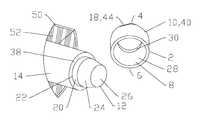
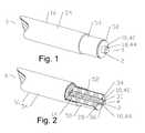
- FIG. 1is a schematic isometric view of an exemplary embodiment of an inner conductor cap with a rotation key formed as male protrusion end facets installed upon the prepared end of coaxial cable.
- FIG. 2is a schematic isometric partial cross-section view of FIG. 1 .
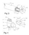
- FIG. 3is a schematic isometric view of the inner conductor cap of FIG. 1 prior to installation with a schematic isometric partially cut-away view of the coaxial cable.
- FIG. 4is an enlarged view of area A of FIG. 3 .
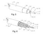
- FIG. 5is a schematic isometric view of an exemplary embodiment of an inner conductor cap, with a rotation key formed as an annular flange, installed upon the prepared end of coaxial cable.
- FIG. 6is a schematic isometric partial cross-section view of FIG. 5 .
- FIG. 7is a schematic isometric view of the inner conductor cap of FIG. 5 prior to installation with a schematic isometric partially cut-away view of the coaxial cable.
- FIG. 8is an enlarged view of area B of FIG. 7 .
- FIG. 9is a schematic isometric view of an exemplary embodiment of a connection socket inner conductor cap, with a rotation key formed as an annular flange, installed upon the prepared end of coaxial cable.
- FIG. 10is a schematic isometric partial cross-section view of FIG. 9 .
- FIG. 11is a schematic isometric view of the inner conductor cap of FIG. 9 prior to installation with a schematic isometric partially cut-away view of the coaxial cable.
- FIG. 12is an enlarged view of area C of FIG. 11 .
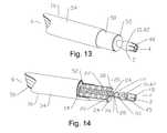
- FIG. 13is a schematic isometric view of an exemplary embodiment of a connection socket inner conductor cap, a rotation key within the connection socket, installed upon the prepared end of coaxial cable.
- FIG. 14is a schematic isometric partial cross-section view of the inner conductor cap of FIG. 13 prior to installation upon the prepared end of coaxial cable, the inner conductor cap being aligned for interconnection.
- FIG. 15is a schematic isometric partial cross-section view of FIG. 13 .
- FIG. 16is an enlarged view of Area D of FIG. 14 .
- FIG. 17is a schematic isometric view of the inner conductor cap of FIG. 13 prior to installation with a schematic isometric partially cut-away view of the coaxial cable.
- FIG. 18is an enlarged view of area E of FIG. 17 .
- Aluminumhas been applied as a cost-effective alternative to copper for conductors in coaxial cables.
- the inventorshave identified several difficulties arising from the interconnection of aluminum inner conductor coaxial cable configurations with prior coaxial cable connectors having inner contact configurations.
- Aluminum oxide surface coatingsquickly form upon air-exposed aluminum surfaces that may degrade traditional mechanical, solder and/or conductive adhesive interconnections.
- prior coaxial connector mechanical interconnection inner contact configurationsare generally incompatible with aluminum inner conductors due to the creep characteristics of aluminum. Galvanic corrosion between the aluminum inner conductor and a dissimilar metal of the inner contact, such as bronze, brass or copper, may contribute to accelerated degradation of the electro-mechanical interconnection.
- the inventorshave recognized that deficiencies in the prior aluminum inner conductor to inner contact interconnections may be obviated by providing an inner conductor cap inner contact dimensioned for friction welding to the inner conductor, enabling a molecular bond interconnection with inherent resistance to corrosion and/or material creep interconnection degradation.
- an inner conductor cap 2are provided with an inner conductor socket 8 at the cable end 6 and an inner conductor interface 10 at the connector end 4 .
- the inner conductor socket 8may be dimensioned to mate with a prepared end 12 of an inner conductor 14 of a coaxial cable 16 .
- At least one material gapmay be provided between a sidewall of the inner conductor socket 8 and an outer diameter surface of the prepared end 12 when the inner conductor cap 2 is mated with the prepared end 12 .
- a rotation key 18is provided dimensioned to mate with a tool for rotating the inner conductor cap, for interconnection via friction welding.
- connector end 4 and cable end 6are applied herein as identifiers for respective ends of both the inner conductor cap 2 and also of discrete elements of the inner conductor cap 2 described herein, to identify same and their respective interconnecting surfaces according to their alignment along a longitudinal axis of the inner conductor cap 2 between a connector end 4 and a cable end 6 .
- the inner conductor cap 2may be formed from a metal and/or metal alloy such as aluminum, brass, phosphor bronze or copper.
- a metal and/or metal alloysuch as aluminum, brass, phosphor bronze or copper.
- the use of metals other than aluminummay, in part, avoid difficulties found in the prior art, discussed above, and/or satisfy end user requirements for specific materials for the contact surfaces of the resulting inner conductor interface 10 .
- the prepared end 12 of the inner conductor 14may be dimensioned with a diameter less than the diameter of the inner conductor 14 , for example with a cylindrical portion 20 proximate a prepared end base 22 and a conical portion 24 proximate a leading end 26 of the prepared end 12 .
- the prepared end 12may, alternatively, be entirely conical, cylindrical or another configuration dimensioned to mate with the desired inner conductor socket 8 resulting in at least one material gap therebetween when the inner conductor cap 2 is seated upon the prepared end 12 .
- an inward projecting plug portionmay be applied to the center of the inner conductor socket 8 , the inward projecting plug portion dimensioned to seat within the hollow inner conductor when the inner conductor cap 2 is seated upon the prepared end 12 .
- the inner conductor socket 8for mating with a prepared end 12 , may, for example, be provided with a conical sidewall 28 with a diameter decreasing toward the connector end 4 .
- the inner conductor socket 8may be also provided with a cylindrical sidewall 30 at a connector end 4 of the inner conductor socket 8 .
- the cylindrical portion 20 of the prepared end 12will, for example, mate with a base portion 32 of the conical sidewall 28 .
- the conical portion 24 of the prepared end 12will, for example, mate with the conical sidewall 28 at a connector end 4 of the conical sidewall 28 and the cylindrical sidewall 30 .
- the at least one material gapmay, for example, be a cable end material gap 34 and/or a connector end material gap 36 . Where cylindrical and/or conical mating surfaces are applied, the resulting material gap(s) may be annular.
- the cable end material gap 34may be formed between the base portion 32 of the conical sidewall 28 , the cylindrical portion 20 and a shoulder 38 of the inner conductor 14 .
- the connector end material gap 36may be formed between the cylindrical sidewall 30 and the conical portion 24 .
- the inner conductor interface 10may, for example, be a male protrusion 40 extending axially toward the connector end 4 , as shown in FIGS. 1-8 , or a female socket 42 , as shown in FIGS. 9-18 , dimensioned to mate with a corresponding male inner conductor connector interface.
- the rotation key 18may be provided with a tool face, such as a slot, aperture, plurality of facets 44 on an outer surface of the male protrusion 40 or the like. The rotation key 18 may, alternatively, as shown in FIGS.
- annular protrusion 46extending radially from an outer surface of the inner conductor cap 2 proximate the cable end 6 of the male protrusion 40 .
- the annular protrusion 46may be similarly provided with facets 44 or other tool face(s) dimensioned to mate with a corresponding tool for rotating the inner conductor cap 2 during friction welding interconnection.
- the female socket 42may, as shown in FIGS. 9-18 , be provided as spring basket 48 .
- the rotation key 18may be provided as, for example, the slots defining the spring basket 48 and/or an annular protrusion 46 extending radially from an outer surface of the inner conductor cap 2 proximate the cable end 6 of the female socket 42 .
- the annular protrusion 46may be provided with facets 44 or other tool face dimensioned to mate with a tool for rotating the inner conductor cap.
- the rotation key 18may, alternatively, as shown in FIGS. 13-18 , be, for example, a rotation socket 45 provided within the female socket 42 at the cable end 6 of the female socket 42 dimensioned to mate with a corresponding tool for rotating the inner conductor cap 2 .
- annular protrusion 46may also provide a surface for impedance matching tuning between the inner conductor 14 , the selected inner connector interface 10 and the selected surrounding connector body (not shown) of the resulting coaxial connector.
- the coaxial cable 16Prior to interconnection via friction welding the coaxial cable 16 may be prepared by removing a portion of an outer conductor 50 of the coaxial cable 16 so that the inner conductor 14 extends therefrom, removing a portion of a dielectric material 52 between the inner conductor 14 and the outer conductor 50 , and stripping back a portion of a jacket 54 from the outer conductor 50 .
- the portion of the inner conductor 14 exposedmay be prepared to form a prepared end 12 dimensioned to mate with the inner conductor socket 8 . This may be done, for example, by grinding the inner conductor 14 . In this way, the prepared end 12 may be provided, for example, with the desired, for example, conical portion 24 and/or a cylindrical portion 20 .
- inner conductor socket 8is seated upon prepared end 12 of the inner conductor 14 .
- the inner conductor cap 2is rotated, for example at a speed of 250 to 500 revolutions per minute, about a longitudinal axis of the prepared end 12 , via the rotation key 18 , while applying longitudinal force driving the inner conductor socket 8 against the prepared end 12 .
- Rotation and longitudinal forceare applied until the prepared end 12 of the inner conductor 14 and/or corresponding surfaces of the inner conductor socket 8 are plasticized sufficiently to create a friction weld between the inner conductor 14 and the inner conductor cap 2 .
- a material interflow between the corresponding surfacesmay flow into and fill or partially fill the material gap(s).
- friction welding utilizing ultrasonic vibrationsuch as torsional vibration
- torsional vibration ultrasonic type friction weldinga torsional vibration is applied to the interconnection via a sonotrode applied to the inner conductor cap 2 , while the coaxial cable 16 and the inner conductor 14 therewithin are held static.
- the torsional vibrationsimilarly generates a friction heat which plasticizes the contact surfaces between the prepared end 12 and the inner conductor socket 8 .
- a suitable frequency and torsional vibration displacement, instead of rotationfor example between 20 and 40 KHz and 20-35 microns may be applied.
- inner conductor cap and interconnection method disclosedmay have significant material cost efficiencies and may provide a permanently sealed inner conductor to inner contact interconnection with reduced size and/or weight requirements.
Landscapes
- Engineering & Computer Science (AREA)
- Manufacturing & Machinery (AREA)
- Coupling Device And Connection With Printed Circuit (AREA)
- Connections Effected By Soldering, Adhesion, Or Permanent Deformation (AREA)
Abstract
Description
| Table of |
| 2 | |
| 4 | |
| 6 | |
| 8 | inner conductor socket |
| 10 | |
| 12 | |
| 14 | |
| 16 | coaxial cable |
| 18 | |
| 20 | |
| 22 | |
| 24 | |
| 26 | leading |
| 28 | |
| 30 | cylindrical sidewall |
| 32 | |
| 34 | cable |
| 36 | connector |
| 38 | shoulder |
| 40 | male protrusion |
| 42 | female socket |
| 44 | |
| 45 | |
| 46 | |
| 48 | |
| 50 | |
| 52 | |
| 54 | jacket |
Claims (11)
Priority Applications (39)
| Application Number | Priority Date | Filing Date | Title |
|---|---|---|---|
| US12/974,765US8563861B2 (en) | 2010-11-22 | 2010-12-21 | Friction weld inner conductor cap and interconnection method |
| US13/161,326US8365404B2 (en) | 2010-11-22 | 2011-06-15 | Method for ultrasonic welding a coaxial cable to a coaxial connector |
| US13/170,958US9728926B2 (en) | 2010-11-22 | 2011-06-28 | Method and apparatus for radial ultrasonic welding interconnected coaxial connector |
| PCT/US2011/046054WO2012071085A1 (en) | 2010-11-22 | 2011-07-30 | Method and apparatus for radial ultrasonic welding interconnected coaxial connector |
| PCT/US2011/046050WO2012071081A1 (en) | 2010-11-22 | 2011-07-30 | Friction weld inner conductor cap and interconnection method |
| CN201180054832.6ACN103299491B (en) | 2010-11-22 | 2011-07-30 | For the method and apparatus of the coaxial ultrasonic bonding interconnection of coaxial connector and coaxial cable |
| EP11842507.3AEP2643894B1 (en) | 2010-11-22 | 2011-07-30 | Method and apparatus for coaxial ultrasonic welding interconnection of coaxial connector and coaxial cable |
| EP11843398.6AEP2643899B1 (en) | 2010-11-22 | 2011-07-30 | Method and apparatus for radial ultrasonic welding interconnected coaxial connector |
| CN201180054850.4ACN103222126B (en) | 2010-11-22 | 2011-07-30 | Method and apparatus for the interconnecting coax adapter of radial ultrasonic welding |
| EP11843863.9AEP2643900A4 (en) | 2010-11-22 | 2011-07-30 | Friction weld inner conductor cap and interconnection method |
| PCT/US2011/046053WO2012071084A1 (en) | 2010-11-22 | 2011-07-30 | Method and apparatus for coaxial ultrasonic welding interconnection of coaxial connector and coaxial cable |
| CN201180054841.5ACN103380547B (en) | 2010-11-22 | 2011-07-30 | Friction welding inner conductor cap and interconnection method |
| US13/240,344US8887388B2 (en) | 2010-11-22 | 2011-09-22 | Method for interconnecting a coaxial connector with a solid outer conductor coaxial cable |
| PCT/US2011/052907WO2012071106A1 (en) | 2010-11-22 | 2011-09-23 | Connector and coaxial cable with molecular bond interconnection |
| EP11843118.8AEP2643897B1 (en) | 2010-11-22 | 2011-09-23 | Connector and coaxial cable with molecular bond interconnection |
| CN201180054849.1ACN103210552B (en) | 2010-11-22 | 2011-09-23 | There is connector and the coaxial cable of molecular bond interconnection |
| US13/294,586US8550843B2 (en) | 2010-11-22 | 2011-11-11 | Tabbed connector interface |
| PCT/US2011/061101WO2012071234A2 (en) | 2010-11-22 | 2011-11-17 | Tabbed connector interface |
| EP11842682.4AEP2643895A4 (en) | 2010-11-22 | 2011-11-17 | Tabbed connector interface |
| CN2011800548519ACN103222119A (en) | 2010-11-22 | 2011-11-17 | Tabbed connector interface |
| US13/673,084US8622768B2 (en) | 2010-11-22 | 2012-11-09 | Connector with capacitively coupled connector interface |
| US13/672,965US8876549B2 (en) | 2010-11-22 | 2012-11-09 | Capacitively coupled flat conductor connector |
| US13/673,373US8622762B2 (en) | 2010-11-22 | 2012-11-09 | Blind mate capacitively coupled connector |
| US13/712,289US9755328B2 (en) | 2010-11-22 | 2012-12-12 | Ultrasonic weld interconnection coaxial connector and interconnection with coaxial cable |
| US14/025,384US20140033529A1 (en) | 2010-11-22 | 2013-09-12 | Friction weld inner conductor cap interconnection method |
| US14/520,749US9583847B2 (en) | 2010-11-22 | 2014-10-22 | Coaxial connector and coaxial cable interconnected via molecular bond |
| US15/443,690US20170170612A1 (en) | 2010-11-22 | 2017-02-27 | Connector and coaxial cable with molecular bond interconnection |
| US15/670,581US10355436B2 (en) | 2010-11-22 | 2017-08-07 | Method and apparatus for radial ultrasonic welding interconnected coaxial connector |
| US15/693,974US10665967B2 (en) | 2010-11-22 | 2017-09-01 | Ultrasonic weld interconnection coaxial connector and interconnection with coaxial cable |
| US16/879,926US10819046B2 (en) | 2010-11-22 | 2020-05-21 | Ultrasonic weld interconnection coaxial connector and interconnection with coaxial cable |
| US17/079,047US11462843B2 (en) | 2010-11-22 | 2020-10-23 | Ultrasonic weld interconnection coaxial connector and interconnection with coaxial cable |
| US17/158,352US11437767B2 (en) | 2010-11-22 | 2021-01-26 | Connector and coaxial cable with molecular bond interconnection |
| US17/158,286US11437766B2 (en) | 2010-11-22 | 2021-01-26 | Connector and coaxial cable with molecular bond interconnection |
| US17/823,202US11735874B2 (en) | 2010-11-22 | 2022-08-30 | Connector and coaxial cable with molecular bond interconnection |
| US17/935,380US11757212B2 (en) | 2010-11-22 | 2022-09-26 | Ultrasonic weld interconnection coaxial connector and interconnection with coaxial cable |
| US18/452,665US12113317B2 (en) | 2010-11-22 | 2023-08-21 | Connector and coaxial cable with molecular bond interconnection |
| US18/464,423US12100925B2 (en) | 2010-11-22 | 2023-09-11 | Ultrasonic weld interconnection coaxial connector and interconnection with coaxial cable |
| US18/819,346US20240421512A1 (en) | 2010-11-22 | 2024-08-29 | Ultrasonic weld interconnection coaxial connector and interconnection with coaxial cable |
| US18/890,033US20250015547A1 (en) | 2010-11-22 | 2024-09-19 | Connector and coaxial cable with molecular bond interconnection |
Applications Claiming Priority (2)
| Application Number | Priority Date | Filing Date | Title |
|---|---|---|---|
| US12/951,558US8826525B2 (en) | 2010-11-22 | 2010-11-22 | Laser weld coaxial connector and interconnection method |
| US12/974,765US8563861B2 (en) | 2010-11-22 | 2010-12-21 | Friction weld inner conductor cap and interconnection method |
Related Parent Applications (3)
| Application Number | Title | Priority Date | Filing Date |
|---|---|---|---|
| US12/951,558Continuation-In-PartUS8826525B2 (en) | 2010-11-22 | 2010-11-22 | Laser weld coaxial connector and interconnection method |
| US12/962,943Continuation-In-PartUS8302296B2 (en) | 2010-11-22 | 2010-12-08 | Friction weld coaxial connector and interconnection method |
| US12/980,013Continuation-In-PartUS8453320B2 (en) | 2010-11-22 | 2010-12-28 | Method of interconnecting a coaxial connector to a coaxial cable via ultrasonic welding |
Related Child Applications (6)
| Application Number | Title | Priority Date | Filing Date |
|---|---|---|---|
| US12/951,558Continuation-In-PartUS8826525B2 (en) | 2010-11-22 | 2010-11-22 | Laser weld coaxial connector and interconnection method |
| US12/980,013Continuation-In-PartUS8453320B2 (en) | 2010-11-22 | 2010-12-28 | Method of interconnecting a coaxial connector to a coaxial cable via ultrasonic welding |
| US13/161,326Continuation-In-PartUS8365404B2 (en) | 2010-11-22 | 2011-06-15 | Method for ultrasonic welding a coaxial cable to a coaxial connector |
| US13/170,958Continuation-In-PartUS9728926B2 (en) | 2010-11-22 | 2011-06-28 | Method and apparatus for radial ultrasonic welding interconnected coaxial connector |
| US13/240,344Continuation-In-PartUS8887388B2 (en) | 2010-11-22 | 2011-09-22 | Method for interconnecting a coaxial connector with a solid outer conductor coaxial cable |
| US14/025,384DivisionUS20140033529A1 (en) | 2010-11-22 | 2013-09-12 | Friction weld inner conductor cap interconnection method |
Publications (2)
| Publication Number | Publication Date |
|---|---|
| US20120125654A1 US20120125654A1 (en) | 2012-05-24 |
| US8563861B2true US8563861B2 (en) | 2013-10-22 |
Family
ID=46063257
Family Applications (2)
| Application Number | Title | Priority Date | Filing Date |
|---|---|---|---|
| US12/974,765Active2031-04-18US8563861B2 (en) | 2010-11-22 | 2010-12-21 | Friction weld inner conductor cap and interconnection method |
| US14/025,384AbandonedUS20140033529A1 (en) | 2010-11-22 | 2013-09-12 | Friction weld inner conductor cap interconnection method |
Family Applications After (1)
| Application Number | Title | Priority Date | Filing Date |
|---|---|---|---|
| US14/025,384AbandonedUS20140033529A1 (en) | 2010-11-22 | 2013-09-12 | Friction weld inner conductor cap interconnection method |
Country Status (4)
| Country | Link |
|---|---|
| US (2) | US8563861B2 (en) |
| EP (1) | EP2643900A4 (en) |
| CN (1) | CN103380547B (en) |
| WO (1) | WO2012071081A1 (en) |
Cited By (2)
| Publication number | Priority date | Publication date | Assignee | Title |
|---|---|---|---|---|
| US20140094070A1 (en)* | 2012-03-23 | 2014-04-03 | Winchester Electronics Corporation | Electrical socket assembly and method of manufacturing same |
| US20240250453A1 (en)* | 2021-07-09 | 2024-07-25 | Aptiv Technologies AG | Wire assembly with welded contact |
Families Citing this family (10)
| Publication number | Priority date | Publication date | Assignee | Title |
|---|---|---|---|---|
| US8622762B2 (en)* | 2010-11-22 | 2014-01-07 | Andrew Llc | Blind mate capacitively coupled connector |
| CH706510A2 (en)* | 2012-05-15 | 2013-11-15 | Huber+Suhner Ag | Method and device for producing an operative connection between a connector and a cable. |
| US9312609B2 (en) | 2012-10-11 | 2016-04-12 | John Mezzalingua Associates, LLC | Coaxial cable device and method involving weld and mate connectivity |
| US9384872B2 (en) | 2012-10-11 | 2016-07-05 | John Mezzalingua Associates, LLC | Coaxial cable device and method involving weld connectivity |
| US9633765B2 (en) | 2012-10-11 | 2017-04-25 | John Mezzalingua Associates, LLC | Coaxial cable device having a helical outer conductor and method for effecting weld connectivity |
| US8801460B2 (en)* | 2012-11-09 | 2014-08-12 | Andrew Llc | RF shielded capacitively coupled connector |
| US9633761B2 (en) | 2014-11-25 | 2017-04-25 | John Mezzalingua Associates, LLC | Center conductor tip |
| DE102019104318C5 (en)* | 2019-02-20 | 2023-06-22 | Auto-Kabel Management Gmbh | Electrical conductor and method for producing an electrical conductor |
| DE102020106415B4 (en)* | 2020-03-10 | 2021-09-30 | Lisa Dräxlmaier GmbH | FRICTION WELDING CONNECTOR AND METHOD FOR MANUFACTURING THEREOF |
| CN114049996A (en)* | 2021-11-17 | 2022-02-15 | 江苏安胜电缆有限公司 | Anti-interference cable convenient to install and used for subway |
Citations (34)
| Publication number | Priority date | Publication date | Assignee | Title |
|---|---|---|---|---|
| US3295095A (en)* | 1964-08-03 | 1966-12-27 | Bendix Corp | Electrical connector means for coaxial cables and the like |
| US3384703A (en)* | 1964-05-26 | 1968-05-21 | Amp Inc | Coaxial connector |
| US4039244A (en)* | 1976-04-09 | 1977-08-02 | Coatings Inc. | Bimetallic electrical connector and method for making the same |
| US4746305A (en) | 1986-09-17 | 1988-05-24 | Taisho Electric Industrial Co. Ltd. | High frequency coaxial connector |
| US5046952A (en) | 1990-06-08 | 1991-09-10 | Amp Incorporated | Right angle connector for mounting to printed circuit board |
| US5137470A (en) | 1991-06-04 | 1992-08-11 | Andrew Corporation | Connector for coaxial cable having a helically corrugated inner conductor |
| US5167533A (en) | 1992-01-08 | 1992-12-01 | Andrew Corporation | Connector for coaxial cable having hollow inner conductors |
| US5186644A (en) | 1991-03-13 | 1993-02-16 | Molex Incorporated | Electrical connector system |
| US5299939A (en) | 1992-03-05 | 1994-04-05 | International Business Machines Corporation | Spring array connector |
| US5354217A (en) | 1993-06-10 | 1994-10-11 | Andrew Corporation | Lightweight connector for a coaxial cable |
| US5545059A (en) | 1995-03-30 | 1996-08-13 | Radio Frequency Systems, Inc. | Connector for a hollow center conductor of a radio frequency cable |
| US5561900A (en) | 1993-05-14 | 1996-10-08 | The Whitaker Corporation | Method of attaching coaxial connector to coaxial cable |
| US5722856A (en) | 1995-05-02 | 1998-03-03 | Huber+Suhner Ag | Apparatus for electrical connection of a coaxial cable and a connector |
| US5775934A (en) | 1996-05-15 | 1998-07-07 | Centerpin Technology, Inc. | Coaxial cable connector |
| US5823824A (en) | 1994-03-07 | 1998-10-20 | Yazaki Corporation | Sealed connector |
| US5830009A (en) | 1995-09-12 | 1998-11-03 | Rosenberger Hochfrequenztechnik Gmbh & Co. | Device for connecting a coaxial plug to a coaxial cable |
| US6133532A (en) | 1998-02-17 | 2000-10-17 | Teracom Components Ab | Contact device |
| US6332808B1 (en) | 1999-09-22 | 2001-12-25 | Mitsubishi Cable Industries, Ltd. | Connector structure |
| US6361364B1 (en)* | 2001-03-02 | 2002-03-26 | Michael Holland | Solderless connector for a coaxial microcable |
| US6607399B2 (en) | 2001-05-29 | 2003-08-19 | Yazaki Corporation | Coax connector for preventing thermal degradation of transmission characteristics |
| US6752668B2 (en) | 2002-08-14 | 2004-06-22 | Konnektech, Ltd. | Electrical connector |
| US6793095B1 (en) | 1998-02-04 | 2004-09-21 | Essef Corporation | Blow-molded pressure tank with spin-welded connector |
| US6814625B2 (en) | 2001-04-10 | 2004-11-09 | Cinch Connectors, Inc. | Electrical connector |
| US6932644B1 (en) | 2004-03-31 | 2005-08-23 | Sri Hermetics Inc. | Dissimilar metal hermetic connector |
| US7044785B2 (en) | 2004-01-16 | 2006-05-16 | Andrew Corporation | Connector and coaxial cable with outer conductor cylindrical section axial compression connection |
| US7067739B2 (en)* | 2003-06-19 | 2006-06-27 | Sumitomo Electric Industries, Ltd. | Joint structure of superconducting cable and insulating spacer for connecting superconducting cable |
| US7144274B2 (en) | 2005-03-07 | 2006-12-05 | Sri Hermetics, Inc. | Hermetically sealed, weldable connectors |
| US7217154B2 (en) | 2005-10-19 | 2007-05-15 | Andrew Corporation | Connector with outer conductor axial compression connection and method of manufacture |
| US7448906B1 (en) | 2007-08-22 | 2008-11-11 | Andrew Llc | Hollow inner conductor contact for coaxial cable connector |
| US7520779B2 (en) | 2007-04-17 | 2009-04-21 | Radiall | 7-16 coaxial flanged receptacles |
| US7607942B1 (en) | 2008-08-14 | 2009-10-27 | Andrew Llc | Multi-shot coaxial connector and method of manufacture |
| US7798847B2 (en) | 2008-10-07 | 2010-09-21 | Andrew Llc | Inner conductor sealing insulator for coaxial connector |
| US20100261361A1 (en) | 2009-04-09 | 2010-10-14 | Lockheed Martin Corporation | High power floating connector |
| US7819698B2 (en) | 2007-08-22 | 2010-10-26 | Andrew Llc | Sealed inner conductor contact for coaxial cable connector |
Family Cites Families (7)
| Publication number | Priority date | Publication date | Assignee | Title |
|---|---|---|---|---|
| US3949466A (en)* | 1974-05-28 | 1976-04-13 | Arthur D. Little Inc. | Process for forming an aluminum electrical conducting wire junction end piece |
| DE3626009A1 (en)* | 1985-08-06 | 1987-02-12 | Kuka Schweissanlagen & Roboter | Method for connecting metallic bodies to other metallic or nonmetallic, in particular ceramic, parts |
| US5802710A (en)* | 1996-10-24 | 1998-09-08 | Andrew Corporation | Method of attaching a connector to a coaxial cable and the resulting assembly |
| JP2000301364A (en)* | 1999-04-12 | 2000-10-31 | Mitsuo Tsukada | Rotation friction agitation joining method of dissimiliar metal material |
| US6793529B1 (en)* | 2003-09-30 | 2004-09-21 | Andrew Corporation | Coaxial connector with positive stop clamping nut attachment |
| US7189114B1 (en)* | 2006-06-29 | 2007-03-13 | Corning Gilbert Inc. | Compression connector |
| DE602009000573D1 (en) | 2009-02-13 | 2011-02-24 | Alcatel Lucent | Method of making a connection between a coaxial cable and a coaxial connector and coaxial cable with coaxial connector termination |
- 2010
- 2010-12-21USUS12/974,765patent/US8563861B2/enactiveActive
- 2011
- 2011-07-30WOPCT/US2011/046050patent/WO2012071081A1/enactiveApplication Filing
- 2011-07-30CNCN201180054841.5Apatent/CN103380547B/ennot_activeExpired - Fee Related
- 2011-07-30EPEP11843863.9Apatent/EP2643900A4/ennot_activeWithdrawn
- 2013
- 2013-09-12USUS14/025,384patent/US20140033529A1/ennot_activeAbandoned
Patent Citations (36)
| Publication number | Priority date | Publication date | Assignee | Title |
|---|---|---|---|---|
| US3384703A (en)* | 1964-05-26 | 1968-05-21 | Amp Inc | Coaxial connector |
| US3295095A (en)* | 1964-08-03 | 1966-12-27 | Bendix Corp | Electrical connector means for coaxial cables and the like |
| US4039244A (en)* | 1976-04-09 | 1977-08-02 | Coatings Inc. | Bimetallic electrical connector and method for making the same |
| US4746305A (en) | 1986-09-17 | 1988-05-24 | Taisho Electric Industrial Co. Ltd. | High frequency coaxial connector |
| US5046952A (en) | 1990-06-08 | 1991-09-10 | Amp Incorporated | Right angle connector for mounting to printed circuit board |
| US5186644A (en) | 1991-03-13 | 1993-02-16 | Molex Incorporated | Electrical connector system |
| US5137470A (en) | 1991-06-04 | 1992-08-11 | Andrew Corporation | Connector for coaxial cable having a helically corrugated inner conductor |
| US5167533A (en) | 1992-01-08 | 1992-12-01 | Andrew Corporation | Connector for coaxial cable having hollow inner conductors |
| US5299939A (en) | 1992-03-05 | 1994-04-05 | International Business Machines Corporation | Spring array connector |
| US5561900A (en) | 1993-05-14 | 1996-10-08 | The Whitaker Corporation | Method of attaching coaxial connector to coaxial cable |
| US6471545B1 (en) | 1993-05-14 | 2002-10-29 | The Whitaker Corporation | Coaxial connector for coaxial cable having a corrugated outer conductor |
| EP0629025A2 (en) | 1993-06-10 | 1994-12-14 | Andrew A.G. | Lightweight connector for coaxial cable |
| US5354217A (en) | 1993-06-10 | 1994-10-11 | Andrew Corporation | Lightweight connector for a coaxial cable |
| US5823824A (en) | 1994-03-07 | 1998-10-20 | Yazaki Corporation | Sealed connector |
| US5545059A (en) | 1995-03-30 | 1996-08-13 | Radio Frequency Systems, Inc. | Connector for a hollow center conductor of a radio frequency cable |
| US5722856A (en) | 1995-05-02 | 1998-03-03 | Huber+Suhner Ag | Apparatus for electrical connection of a coaxial cable and a connector |
| US5830009A (en) | 1995-09-12 | 1998-11-03 | Rosenberger Hochfrequenztechnik Gmbh & Co. | Device for connecting a coaxial plug to a coaxial cable |
| US5775934A (en) | 1996-05-15 | 1998-07-07 | Centerpin Technology, Inc. | Coaxial cable connector |
| US6793095B1 (en) | 1998-02-04 | 2004-09-21 | Essef Corporation | Blow-molded pressure tank with spin-welded connector |
| US6133532A (en) | 1998-02-17 | 2000-10-17 | Teracom Components Ab | Contact device |
| US6332808B1 (en) | 1999-09-22 | 2001-12-25 | Mitsubishi Cable Industries, Ltd. | Connector structure |
| US6361364B1 (en)* | 2001-03-02 | 2002-03-26 | Michael Holland | Solderless connector for a coaxial microcable |
| US6814625B2 (en) | 2001-04-10 | 2004-11-09 | Cinch Connectors, Inc. | Electrical connector |
| US6607399B2 (en) | 2001-05-29 | 2003-08-19 | Yazaki Corporation | Coax connector for preventing thermal degradation of transmission characteristics |
| US6752668B2 (en) | 2002-08-14 | 2004-06-22 | Konnektech, Ltd. | Electrical connector |
| US7067739B2 (en)* | 2003-06-19 | 2006-06-27 | Sumitomo Electric Industries, Ltd. | Joint structure of superconducting cable and insulating spacer for connecting superconducting cable |
| US7044785B2 (en) | 2004-01-16 | 2006-05-16 | Andrew Corporation | Connector and coaxial cable with outer conductor cylindrical section axial compression connection |
| US6932644B1 (en) | 2004-03-31 | 2005-08-23 | Sri Hermetics Inc. | Dissimilar metal hermetic connector |
| US7144274B2 (en) | 2005-03-07 | 2006-12-05 | Sri Hermetics, Inc. | Hermetically sealed, weldable connectors |
| US7217154B2 (en) | 2005-10-19 | 2007-05-15 | Andrew Corporation | Connector with outer conductor axial compression connection and method of manufacture |
| US7520779B2 (en) | 2007-04-17 | 2009-04-21 | Radiall | 7-16 coaxial flanged receptacles |
| US7448906B1 (en) | 2007-08-22 | 2008-11-11 | Andrew Llc | Hollow inner conductor contact for coaxial cable connector |
| US7819698B2 (en) | 2007-08-22 | 2010-10-26 | Andrew Llc | Sealed inner conductor contact for coaxial cable connector |
| US7607942B1 (en) | 2008-08-14 | 2009-10-27 | Andrew Llc | Multi-shot coaxial connector and method of manufacture |
| US7798847B2 (en) | 2008-10-07 | 2010-09-21 | Andrew Llc | Inner conductor sealing insulator for coaxial connector |
| US20100261361A1 (en) | 2009-04-09 | 2010-10-14 | Lockheed Martin Corporation | High power floating connector |
Non-Patent Citations (1)
| Title |
|---|
| Sung Hee Kim, International Search Report from related PCT filing PCT/US/2011/046050, Seo-Gu, Daejeon, Republic of South Korea, Feb. 9, 2012. |
Cited By (3)
| Publication number | Priority date | Publication date | Assignee | Title |
|---|---|---|---|---|
| US20140094070A1 (en)* | 2012-03-23 | 2014-04-03 | Winchester Electronics Corporation | Electrical socket assembly and method of manufacturing same |
| US20240250453A1 (en)* | 2021-07-09 | 2024-07-25 | Aptiv Technologies AG | Wire assembly with welded contact |
| US12438289B2 (en)* | 2021-07-09 | 2025-10-07 | Aptiv Technologies AG | Wire assembly with welded contact |
Also Published As
| Publication number | Publication date |
|---|---|
| US20140033529A1 (en) | 2014-02-06 |
| WO2012071081A1 (en) | 2012-05-31 |
| US20120125654A1 (en) | 2012-05-24 |
| EP2643900A1 (en) | 2013-10-02 |
| CN103380547A (en) | 2013-10-30 |
| CN103380547B (en) | 2016-06-15 |
| EP2643900A4 (en) | 2014-04-09 |
Similar Documents
| Publication | Publication Date | Title |
|---|---|---|
| US8563861B2 (en) | Friction weld inner conductor cap and interconnection method | |
| US11462843B2 (en) | Ultrasonic weld interconnection coaxial connector and interconnection with coaxial cable | |
| US10355436B2 (en) | Method and apparatus for radial ultrasonic welding interconnected coaxial connector | |
| US8302296B2 (en) | Friction weld coaxial connector and interconnection method | |
| US8453320B2 (en) | Method of interconnecting a coaxial connector to a coaxial cable via ultrasonic welding | |
| US8550843B2 (en) | Tabbed connector interface | |
| US8622762B2 (en) | Blind mate capacitively coupled connector | |
| US8479383B2 (en) | Friction weld coaxial connector and interconnection method | |
| US9761959B2 (en) | Ultrasonic weld coaxial connector | |
| EP2777098B1 (en) | Blind mate capacitively coupled connector | |
| CN103875136A (en) | Connector with capacitively coupled connector interface | |
| CN103843207B (en) | Blind Mate Capacitive Coupling Connectors |
Legal Events
| Date | Code | Title | Description |
|---|---|---|---|
| AS | Assignment | Owner name:ANDREW LLC, NORTH CAROLINA Free format text:ASSIGNMENT OF ASSIGNORS INTEREST;ASSIGNORS:VAN SWEARINGEN, KENDRICK;VACCARO, RONALD A.;REEL/FRAME:025533/0219 Effective date:20101221 | |
| AS | Assignment | Owner name:JPMORGAN CHASE BANK, N.A., AS COLLATERAL AGENT, NE Free format text:SECURITY AGREEMENT;ASSIGNORS:ALLEN TELECOM LLC, A DELAWARE LLC;ANDREW LLC, A DELAWARE LLC;COMMSCOPE, INC. OF NORTH CAROLINA, A NORTH CAROLINA CORPORATION;REEL/FRAME:026276/0363 Effective date:20110114 | |
| AS | Assignment | Owner name:JPMORGAN CHASE BANK, N.A., AS COLLATERAL AGENT, NE Free format text:SECURITY AGREEMENT;ASSIGNORS:ALLEN TELECOM LLC, A DELAWARE LLC;ANDREW LLC, A DELAWARE LLC;COMMSCOPE, INC OF NORTH CAROLINA, A NORTH CAROLINA CORPORATION;REEL/FRAME:026272/0543 Effective date:20110114 | |
| STCF | Information on status: patent grant | Free format text:PATENTED CASE | |
| AS | Assignment | Owner name:COMMSCOPE TECHNOLOGIES LLC, NORTH CAROLINA Free format text:CHANGE OF NAME;ASSIGNOR:ANDREW LLC;REEL/FRAME:035286/0001 Effective date:20150301 | |
| AS | Assignment | Owner name:WILMINGTON TRUST, NATIONAL ASSOCIATION, AS COLLATERAL AGENT, CONNECTICUT Free format text:SECURITY INTEREST;ASSIGNORS:ALLEN TELECOM LLC;COMMSCOPE TECHNOLOGIES LLC;COMMSCOPE, INC. OF NORTH CAROLINA;AND OTHERS;REEL/FRAME:036201/0283 Effective date:20150611 Owner name:WILMINGTON TRUST, NATIONAL ASSOCIATION, AS COLLATE Free format text:SECURITY INTEREST;ASSIGNORS:ALLEN TELECOM LLC;COMMSCOPE TECHNOLOGIES LLC;COMMSCOPE, INC. OF NORTH CAROLINA;AND OTHERS;REEL/FRAME:036201/0283 Effective date:20150611 | |
| AS | Assignment | Owner name:COMMSCOPE, INC. OF NORTH CAROLINA, NORTH CAROLINA Free format text:RELEASE OF SECURITY INTEREST PATENTS (RELEASES RF 036201/0283);ASSIGNOR:WILMINGTON TRUST, NATIONAL ASSOCIATION;REEL/FRAME:042126/0434 Effective date:20170317 Owner name:COMMSCOPE TECHNOLOGIES LLC, NORTH CAROLINA Free format text:RELEASE OF SECURITY INTEREST PATENTS (RELEASES RF 036201/0283);ASSIGNOR:WILMINGTON TRUST, NATIONAL ASSOCIATION;REEL/FRAME:042126/0434 Effective date:20170317 Owner name:ALLEN TELECOM LLC, NORTH CAROLINA Free format text:RELEASE OF SECURITY INTEREST PATENTS (RELEASES RF 036201/0283);ASSIGNOR:WILMINGTON TRUST, NATIONAL ASSOCIATION;REEL/FRAME:042126/0434 Effective date:20170317 Owner name:REDWOOD SYSTEMS, INC., NORTH CAROLINA Free format text:RELEASE OF SECURITY INTEREST PATENTS (RELEASES RF 036201/0283);ASSIGNOR:WILMINGTON TRUST, NATIONAL ASSOCIATION;REEL/FRAME:042126/0434 Effective date:20170317 | |
| FPAY | Fee payment | Year of fee payment:4 | |
| AS | Assignment | Owner name:ALLEN TELECOM LLC, ILLINOIS Free format text:RELEASE BY SECURED PARTY;ASSIGNOR:JPMORGAN CHASE BANK, N.A.;REEL/FRAME:048840/0001 Effective date:20190404 Owner name:COMMSCOPE TECHNOLOGIES LLC, NORTH CAROLINA Free format text:RELEASE BY SECURED PARTY;ASSIGNOR:JPMORGAN CHASE BANK, N.A.;REEL/FRAME:048840/0001 Effective date:20190404 Owner name:REDWOOD SYSTEMS, INC., NORTH CAROLINA Free format text:RELEASE BY SECURED PARTY;ASSIGNOR:JPMORGAN CHASE BANK, N.A.;REEL/FRAME:048840/0001 Effective date:20190404 Owner name:COMMSCOPE, INC. OF NORTH CAROLINA, NORTH CAROLINA Free format text:RELEASE BY SECURED PARTY;ASSIGNOR:JPMORGAN CHASE BANK, N.A.;REEL/FRAME:048840/0001 Effective date:20190404 Owner name:ANDREW LLC, NORTH CAROLINA Free format text:RELEASE BY SECURED PARTY;ASSIGNOR:JPMORGAN CHASE BANK, N.A.;REEL/FRAME:048840/0001 Effective date:20190404 Owner name:COMMSCOPE, INC. OF NORTH CAROLINA, NORTH CAROLINA Free format text:RELEASE BY SECURED PARTY;ASSIGNOR:JPMORGAN CHASE BANK, N.A.;REEL/FRAME:049260/0001 Effective date:20190404 Owner name:REDWOOD SYSTEMS, INC., NORTH CAROLINA Free format text:RELEASE BY SECURED PARTY;ASSIGNOR:JPMORGAN CHASE BANK, N.A.;REEL/FRAME:049260/0001 Effective date:20190404 Owner name:ANDREW LLC, NORTH CAROLINA Free format text:RELEASE BY SECURED PARTY;ASSIGNOR:JPMORGAN CHASE BANK, N.A.;REEL/FRAME:049260/0001 Effective date:20190404 Owner name:COMMSCOPE TECHNOLOGIES LLC, NORTH CAROLINA Free format text:RELEASE BY SECURED PARTY;ASSIGNOR:JPMORGAN CHASE BANK, N.A.;REEL/FRAME:049260/0001 Effective date:20190404 Owner name:ALLEN TELECOM LLC, ILLINOIS Free format text:RELEASE BY SECURED PARTY;ASSIGNOR:JPMORGAN CHASE BANK, N.A.;REEL/FRAME:049260/0001 Effective date:20190404 | |
| AS | Assignment | Owner name:WILMINGTON TRUST, NATIONAL ASSOCIATION, AS COLLATE Free format text:PATENT SECURITY AGREEMENT;ASSIGNOR:COMMSCOPE TECHNOLOGIES LLC;REEL/FRAME:049892/0051 Effective date:20190404 Owner name:JPMORGAN CHASE BANK, N.A., NEW YORK Free format text:TERM LOAN SECURITY AGREEMENT;ASSIGNORS:COMMSCOPE, INC. OF NORTH CAROLINA;COMMSCOPE TECHNOLOGIES LLC;ARRIS ENTERPRISES LLC;AND OTHERS;REEL/FRAME:049905/0504 Effective date:20190404 Owner name:JPMORGAN CHASE BANK, N.A., NEW YORK Free format text:ABL SECURITY AGREEMENT;ASSIGNORS:COMMSCOPE, INC. OF NORTH CAROLINA;COMMSCOPE TECHNOLOGIES LLC;ARRIS ENTERPRISES LLC;AND OTHERS;REEL/FRAME:049892/0396 Effective date:20190404 Owner name:WILMINGTON TRUST, NATIONAL ASSOCIATION, AS COLLATERAL AGENT, CONNECTICUT Free format text:PATENT SECURITY AGREEMENT;ASSIGNOR:COMMSCOPE TECHNOLOGIES LLC;REEL/FRAME:049892/0051 Effective date:20190404 | |
| FEPP | Fee payment procedure | Free format text:MAINTENANCE FEE REMINDER MAILED (ORIGINAL EVENT CODE: REM.); ENTITY STATUS OF PATENT OWNER: LARGE ENTITY Free format text:7.5 YR SURCHARGE - LATE PMT W/IN 6 MO, LARGE ENTITY (ORIGINAL EVENT CODE: M1555); ENTITY STATUS OF PATENT OWNER: LARGE ENTITY | |
| MAFP | Maintenance fee payment | Free format text:PAYMENT OF MAINTENANCE FEE, 8TH YEAR, LARGE ENTITY (ORIGINAL EVENT CODE: M1552); ENTITY STATUS OF PATENT OWNER: LARGE ENTITY Year of fee payment:8 | |
| AS | Assignment | Owner name:WILMINGTON TRUST, DELAWARE Free format text:SECURITY INTEREST;ASSIGNORS:ARRIS SOLUTIONS, INC.;ARRIS ENTERPRISES LLC;COMMSCOPE TECHNOLOGIES LLC;AND OTHERS;REEL/FRAME:060752/0001 Effective date:20211115 | |
| AS | Assignment | Owner name:OUTDOOR WIRELESS NETWORKS LLC, NORTH CAROLINA Free format text:ASSIGNMENT OF ASSIGNORS INTEREST;ASSIGNOR:COMMSCOPE TECHNOLOGIES LLC;REEL/FRAME:068107/0089 Effective date:20240701 | |
| AS | Assignment | Owner name:JPMORGAN CHASE BANK, N.A., AS COLLATERAL AGENT, NEW YORK Free format text:PATENT SECURITY AGREEMENT (TERM);ASSIGNOR:OUTDOOR WIRELESS NETWORKS LLC;REEL/FRAME:068770/0632 Effective date:20240813 Owner name:JPMORGAN CHASE BANK, N.A., AS COLLATERAL AGENT, NEW YORK Free format text:PATENT SECURITY AGREEMENT (ABL);ASSIGNOR:OUTDOOR WIRELESS NETWORKS LLC;REEL/FRAME:068770/0460 Effective date:20240813 | |
| AS | Assignment | Owner name:APOLLO ADMINISTRATIVE AGENCY LLC, NEW YORK Free format text:SECURITY INTEREST;ASSIGNORS:ARRIS ENTERPRISES LLC;COMMSCOPE TECHNOLOGIES LLC;COMMSCOPE INC., OF NORTH CAROLINA;AND OTHERS;REEL/FRAME:069889/0114 Effective date:20241217 | |
| AS | Assignment | Owner name:OUTDOOR WIRELESS NETWORKS LLC, NORTH CAROLINA Free format text:RELEASE OF SECURITY INTEREST AT REEL/FRAME 068770/0632;ASSIGNOR:JPMORGAN CHASE BANK, N.A., AS COLLATERAL AGENT;REEL/FRAME:069743/0264 Effective date:20241217 Owner name:RUCKUS WIRELESS, LLC (F/K/A RUCKUS WIRELESS, INC.), NORTH CAROLINA Free format text:RELEASE OF SECURITY INTEREST AT REEL/FRAME 049905/0504;ASSIGNOR:JPMORGAN CHASE BANK, N.A., AS COLLATERAL AGENT;REEL/FRAME:071477/0255 Effective date:20241217 Owner name:COMMSCOPE TECHNOLOGIES LLC, NORTH CAROLINA Free format text:RELEASE OF SECURITY INTEREST AT REEL/FRAME 049905/0504;ASSIGNOR:JPMORGAN CHASE BANK, N.A., AS COLLATERAL AGENT;REEL/FRAME:071477/0255 Effective date:20241217 Owner name:COMMSCOPE, INC. OF NORTH CAROLINA, NORTH CAROLINA Free format text:RELEASE OF SECURITY INTEREST AT REEL/FRAME 049905/0504;ASSIGNOR:JPMORGAN CHASE BANK, N.A., AS COLLATERAL AGENT;REEL/FRAME:071477/0255 Effective date:20241217 Owner name:ARRIS SOLUTIONS, INC., NORTH CAROLINA Free format text:RELEASE OF SECURITY INTEREST AT REEL/FRAME 049905/0504;ASSIGNOR:JPMORGAN CHASE BANK, N.A., AS COLLATERAL AGENT;REEL/FRAME:071477/0255 Effective date:20241217 Owner name:ARRIS TECHNOLOGY, INC., NORTH CAROLINA Free format text:RELEASE OF SECURITY INTEREST AT REEL/FRAME 049905/0504;ASSIGNOR:JPMORGAN CHASE BANK, N.A., AS COLLATERAL AGENT;REEL/FRAME:071477/0255 Effective date:20241217 Owner name:ARRIS ENTERPRISES LLC (F/K/A ARRIS ENTERPRISES, INC.), NORTH CAROLINA Free format text:RELEASE OF SECURITY INTEREST AT REEL/FRAME 049905/0504;ASSIGNOR:JPMORGAN CHASE BANK, N.A., AS COLLATERAL AGENT;REEL/FRAME:071477/0255 Effective date:20241217 | |
| AS | Assignment | Owner name:OUTDOOR WIRELESS NETWORKS LLC, NORTH CAROLINA Free format text:PARTIAL TERMINATION AND RELEASE OF SECURITY INTEREST IN PATENTS RECORDED AT REEL 069889/FRAME 0114;ASSIGNOR:APOLLO ADMINISTRATIVE AGENCY LLC;REEL/FRAME:070154/0341 Effective date:20250131 Owner name:OUTDOOR WIRELESS NETWORKS LLC, NORTH CAROLINA Free format text:PARTIAL TERMINATION AND RELEASE OF SECURITY INTEREST IN PATENTS;ASSIGNOR:U.S. BANK TRUST COMPANY, NATIONAL ASSOCIATION;REEL/FRAME:070154/0183 Effective date:20250131 Owner name:OUTDOOR WIRELESS NETWORKS LLC, NORTH CAROLINA Free format text:RELEASE (REEL 068770 / FRAME 0460);ASSIGNOR:JPMORGAN CHASE BANK, N.A.;REEL/FRAME:070149/0432 Effective date:20250131 | |
| FEPP | Fee payment procedure | Free format text:MAINTENANCE FEE REMINDER MAILED (ORIGINAL EVENT CODE: REM.); ENTITY STATUS OF PATENT OWNER: LARGE ENTITY |