US8563334B2 - Method to remove sapphire substrate - Google Patents
Method to remove sapphire substrateDownload PDFInfo
- Publication number
- US8563334B2 US8563334B2US12/881,457US88145710AUS8563334B2US 8563334 B2US8563334 B2US 8563334B2US 88145710 AUS88145710 AUS 88145710AUS 8563334 B2US8563334 B2US 8563334B2
- Authority
- US
- United States
- Prior art keywords
- layer
- substrate
- light
- forming
- doped
- Prior art date
- Legal status (The legal status is an assumption and is not a legal conclusion. Google has not performed a legal analysis and makes no representation as to the accuracy of the status listed.)
- Active
Links
- 239000000758substrateSubstances0.000titleclaimsabstractdescription119
- 229910052594sapphireInorganic materials0.000titleclaimsabstractdescription30
- 239000010980sapphireSubstances0.000titleclaimsabstractdescription30
- 238000000034methodMethods0.000titleclaimsdescription77
- 238000000227grindingMethods0.000claimsabstractdescription32
- 238000005530etchingMethods0.000claimsabstractdescription22
- 238000001039wet etchingMethods0.000claimsabstractdescription13
- 239000003082abrasive agentSubstances0.000claimsabstractdescription8
- 229910052751metalInorganic materials0.000claimsdescription70
- 239000002184metalSubstances0.000claimsdescription70
- 230000008569processEffects0.000claimsdescription45
- 238000002161passivationMethods0.000claimsdescription32
- 239000000463materialSubstances0.000claimsdescription29
- NBIIXXVUZAFLBC-UHFFFAOYSA-NPhosphoric acidChemical compoundOP(O)(O)=ONBIIXXVUZAFLBC-UHFFFAOYSA-N0.000claimsdescription14
- 229920002120photoresistant polymerPolymers0.000claimsdescription14
- XUIMIQQOPSSXEZ-UHFFFAOYSA-NSiliconChemical compound[Si]XUIMIQQOPSSXEZ-UHFFFAOYSA-N0.000claimsdescription13
- 238000004519manufacturing processMethods0.000claimsdescription13
- 229910052710siliconInorganic materials0.000claimsdescription13
- 239000010703siliconSubstances0.000claimsdescription13
- QAOWNCQODCNURD-UHFFFAOYSA-NSulfuric acidChemical compoundOS(O)(=O)=OQAOWNCQODCNURD-UHFFFAOYSA-N0.000claimsdescription12
- 238000009616inductively coupled plasmaMethods0.000claimsdescription8
- 238000000151depositionMethods0.000claimsdescription7
- 239000012535impuritySubstances0.000claimsdescription7
- 239000002245particleSubstances0.000claimsdescription7
- 239000000203mixtureSubstances0.000claimsdescription6
- 229910000147aluminium phosphateInorganic materials0.000claimsdescription5
- 229910052736halogenInorganic materials0.000claimsdescription2
- 150000002367halogensChemical class0.000claimsdescription2
- 238000001312dry etchingMethods0.000abstractdescription7
- 229910002601GaNInorganic materials0.000description19
- JMASRVWKEDWRBT-UHFFFAOYSA-NGallium nitrideChemical compound[Ga]#NJMASRVWKEDWRBT-UHFFFAOYSA-N0.000description19
- PCHJSUWPFVWCPO-UHFFFAOYSA-NgoldChemical compound[Au]PCHJSUWPFVWCPO-UHFFFAOYSA-N0.000description11
- 239000010931goldSubstances0.000description11
- 229910052737goldInorganic materials0.000description9
- 239000004065semiconductorSubstances0.000description8
- QTBSBXVTEAMEQO-UHFFFAOYSA-NAcetic acidChemical compoundCC(O)=OQTBSBXVTEAMEQO-UHFFFAOYSA-N0.000description6
- XKRFYHLGVUSROY-UHFFFAOYSA-NArgonChemical compound[Ar]XKRFYHLGVUSROY-UHFFFAOYSA-N0.000description6
- PXHVJJICTQNCMI-UHFFFAOYSA-NNickelChemical compound[Ni]PXHVJJICTQNCMI-UHFFFAOYSA-N0.000description6
- 229910052738indiumInorganic materials0.000description6
- APFVFJFRJDLVQX-UHFFFAOYSA-Nindium atomChemical compound[In]APFVFJFRJDLVQX-UHFFFAOYSA-N0.000description6
- 238000012360testing methodMethods0.000description6
- IJGRMHOSHXDMSA-UHFFFAOYSA-NAtomic nitrogenChemical compoundN#NIJGRMHOSHXDMSA-UHFFFAOYSA-N0.000description5
- 229910003460diamondInorganic materials0.000description5
- 239000010432diamondSubstances0.000description5
- 238000005240physical vapour depositionMethods0.000description5
- VYPSYNLAJGMNEJ-UHFFFAOYSA-NSilicium dioxideChemical compoundO=[Si]=OVYPSYNLAJGMNEJ-UHFFFAOYSA-N0.000description4
- RTAQQCXQSZGOHL-UHFFFAOYSA-NTitaniumChemical compound[Ti]RTAQQCXQSZGOHL-UHFFFAOYSA-N0.000description4
- 238000005229chemical vapour depositionMethods0.000description4
- 238000000623plasma-assisted chemical vapour depositionMethods0.000description4
- BASFCYQUMIYNBI-UHFFFAOYSA-NplatinumChemical compound[Pt]BASFCYQUMIYNBI-UHFFFAOYSA-N0.000description4
- 229910052814silicon oxideInorganic materials0.000description4
- VZGDMQKNWNREIO-UHFFFAOYSA-NtetrachloromethaneChemical compoundClC(Cl)(Cl)ClVZGDMQKNWNREIO-UHFFFAOYSA-N0.000description4
- 229910052719titaniumInorganic materials0.000description4
- 239000010936titaniumSubstances0.000description4
- 235000012431wafersNutrition0.000description4
- 229910015844BCl3Inorganic materials0.000description3
- KZBUYRJDOAKODT-UHFFFAOYSA-NChlorineChemical compoundClClKZBUYRJDOAKODT-UHFFFAOYSA-N0.000description3
- GRYLNZFGIOXLOG-UHFFFAOYSA-NNitric acidChemical compoundO[N+]([O-])=OGRYLNZFGIOXLOG-UHFFFAOYSA-N0.000description3
- 229910045601alloyInorganic materials0.000description3
- 239000000956alloySubstances0.000description3
- 229910052782aluminiumInorganic materials0.000description3
- XAGFODPZIPBFFR-UHFFFAOYSA-NaluminiumChemical compound[Al]XAGFODPZIPBFFR-UHFFFAOYSA-N0.000description3
- 229910052786argonInorganic materials0.000description3
- 230000015572biosynthetic processEffects0.000description3
- 230000006378damageEffects0.000description3
- 230000008021depositionEffects0.000description3
- 238000005137deposition processMethods0.000description3
- -1for exampleSubstances0.000description3
- 229910017604nitric acidInorganic materials0.000description3
- 238000001020plasma etchingMethods0.000description3
- 238000012545processingMethods0.000description3
- FAQYAMRNWDIXMY-UHFFFAOYSA-NtrichloroboraneChemical compoundClB(Cl)ClFAQYAMRNWDIXMY-UHFFFAOYSA-N0.000description3
- XLYOFNOQVPJJNP-UHFFFAOYSA-NwaterSubstancesOXLYOFNOQVPJJNP-UHFFFAOYSA-N0.000description3
- 229910001020Au alloyInorganic materials0.000description2
- ZAMOUSCENKQFHK-UHFFFAOYSA-NChlorine atomChemical compound[Cl]ZAMOUSCENKQFHK-UHFFFAOYSA-N0.000description2
- RYGMFSIKBFXOCR-UHFFFAOYSA-NCopperChemical compound[Cu]RYGMFSIKBFXOCR-UHFFFAOYSA-N0.000description2
- 229910000990Ni alloyInorganic materials0.000description2
- OAICVXFJPJFONN-UHFFFAOYSA-NPhosphorusChemical compound[P]OAICVXFJPJFONN-UHFFFAOYSA-N0.000description2
- 229910052581Si3N4Inorganic materials0.000description2
- 229910001128Sn alloyInorganic materials0.000description2
- 239000011149active materialSubstances0.000description2
- 239000000460chlorineSubstances0.000description2
- 229910052801chlorineInorganic materials0.000description2
- AFYPFACVUDMOHA-UHFFFAOYSA-NchlorotrifluoromethaneChemical compoundFC(F)(F)ClAFYPFACVUDMOHA-UHFFFAOYSA-N0.000description2
- 229910052802copperInorganic materials0.000description2
- 239000010949copperSubstances0.000description2
- 230000002950deficientEffects0.000description2
- PXBRQCKWGAHEHS-UHFFFAOYSA-NdichlorodifluoromethaneChemical compoundFC(F)(Cl)ClPXBRQCKWGAHEHS-UHFFFAOYSA-N0.000description2
- 230000005496eutecticsEffects0.000description2
- 239000007789gasSubstances0.000description2
- 238000011065in-situ storageMethods0.000description2
- 150000002500ionsChemical class0.000description2
- 229910052743kryptonInorganic materials0.000description2
- DNNSSWSSYDEUBZ-UHFFFAOYSA-Nkrypton atomChemical compound[Kr]DNNSSWSSYDEUBZ-UHFFFAOYSA-N0.000description2
- 239000007769metal materialSubstances0.000description2
- 229910044991metal oxideInorganic materials0.000description2
- 150000004706metal oxidesChemical class0.000description2
- 229910052759nickelInorganic materials0.000description2
- 229910052757nitrogenInorganic materials0.000description2
- 238000000059patterningMethods0.000description2
- 229910052697platinumInorganic materials0.000description2
- 238000005498polishingMethods0.000description2
- 230000005855radiationEffects0.000description2
- HBMJWWWQQXIZIP-UHFFFAOYSA-Nsilicon carbideChemical compound[Si+]#[C-]HBMJWWWQQXIZIP-UHFFFAOYSA-N0.000description2
- 229910010271silicon carbideInorganic materials0.000description2
- HQVNEWCFYHHQES-UHFFFAOYSA-Nsilicon nitrideChemical compoundN12[Si]34N5[Si]62N3[Si]51N64HQVNEWCFYHHQES-UHFFFAOYSA-N0.000description2
- 229910052709silverInorganic materials0.000description2
- 239000004332silverSubstances0.000description2
- 239000000126substanceSubstances0.000description2
- CYRMSUTZVYGINF-UHFFFAOYSA-NtrichlorofluoromethaneChemical compoundFC(Cl)(Cl)ClCYRMSUTZVYGINF-UHFFFAOYSA-N0.000description2
- 229910052724xenonInorganic materials0.000description2
- FHNFHKCVQCLJFQ-UHFFFAOYSA-Nxenon atomChemical compound[Xe]FHNFHKCVQCLJFQ-UHFFFAOYSA-N0.000description2
- 229910001316Ag alloyInorganic materials0.000description1
- WKBOTKDWSSQWDR-UHFFFAOYSA-NBromine atomChemical compound[Br]WKBOTKDWSSQWDR-UHFFFAOYSA-N0.000description1
- VYZAMTAEIAYCRO-UHFFFAOYSA-NChromiumChemical compound[Cr]VYZAMTAEIAYCRO-UHFFFAOYSA-N0.000description1
- 239000004593EpoxySubstances0.000description1
- YCKRFDGAMUMZLT-UHFFFAOYSA-NFluorine atomChemical compound[F]YCKRFDGAMUMZLT-UHFFFAOYSA-N0.000description1
- XPDWGBQVDMORPB-UHFFFAOYSA-NFluoroformChemical compoundFC(F)FXPDWGBQVDMORPB-UHFFFAOYSA-N0.000description1
- GYHNNYVSQQEPJS-UHFFFAOYSA-NGalliumChemical group[Ga]GYHNNYVSQQEPJS-UHFFFAOYSA-N0.000description1
- BQCADISMDOOEFD-UHFFFAOYSA-NSilverChemical compound[Ag]BQCADISMDOOEFD-UHFFFAOYSA-N0.000description1
- ATJFFYVFTNAWJD-UHFFFAOYSA-NTinChemical compound[Sn]ATJFFYVFTNAWJD-UHFFFAOYSA-N0.000description1
- 230000004075alterationEffects0.000description1
- QVGXLLKOCUKJST-UHFFFAOYSA-Natomic oxygenChemical compound[O]QVGXLLKOCUKJST-UHFFFAOYSA-N0.000description1
- 230000009286beneficial effectEffects0.000description1
- GDTBXPJZTBHREO-UHFFFAOYSA-NbromineSubstancesBrBrGDTBXPJZTBHREO-UHFFFAOYSA-N0.000description1
- 229910052794bromiumInorganic materials0.000description1
- 239000003990capacitorSubstances0.000description1
- 239000000919ceramicSubstances0.000description1
- 238000006243chemical reactionMethods0.000description1
- 229910052804chromiumInorganic materials0.000description1
- 239000011651chromiumSubstances0.000description1
- 239000011248coating agentSubstances0.000description1
- 238000000576coating methodMethods0.000description1
- 230000000295complement effectEffects0.000description1
- 150000001875compoundsChemical class0.000description1
- 238000010276constructionMethods0.000description1
- 238000001816coolingMethods0.000description1
- PMHQVHHXPFUNSP-UHFFFAOYSA-Mcopper(1+);methylsulfanylmethane;bromideChemical compoundBr[Cu].CSCPMHQVHHXPFUNSP-UHFFFAOYSA-M0.000description1
- 239000013078crystalSubstances0.000description1
- 238000005520cutting processMethods0.000description1
- 230000007423decreaseEffects0.000description1
- 230000007547defectEffects0.000description1
- 238000013461designMethods0.000description1
- 230000001066destructive effectEffects0.000description1
- 238000011161developmentMethods0.000description1
- 238000010586diagramMethods0.000description1
- 229910001873dinitrogenInorganic materials0.000description1
- 230000000694effectsEffects0.000description1
- 238000004070electrodepositionMethods0.000description1
- 230000005670electromagnetic radiationEffects0.000description1
- 238000000605extractionMethods0.000description1
- 230000005669field effectEffects0.000description1
- 229910052731fluorineInorganic materials0.000description1
- 239000011737fluorineSubstances0.000description1
- AMGQUBHHOARCQH-UHFFFAOYSA-Nindium;oxotinChemical compound[In].[Sn]=OAMGQUBHHOARCQH-UHFFFAOYSA-N0.000description1
- 229910001092metal group alloyInorganic materials0.000description1
- 238000001465metallisationMethods0.000description1
- 150000002739metalsChemical class0.000description1
- 238000004377microelectronicMethods0.000description1
- 238000000465mouldingMethods0.000description1
- 239000001301oxygenSubstances0.000description1
- 229910052760oxygenInorganic materials0.000description1
- 238000004806packaging method and processMethods0.000description1
- 230000000737periodic effectEffects0.000description1
- 238000007747platingMethods0.000description1
- 238000002360preparation methodMethods0.000description1
- 230000004044responseEffects0.000description1
- 239000000523sampleSubstances0.000description1
- 229910000679solderInorganic materials0.000description1
- 239000007787solidSubstances0.000description1
- 238000006467substitution reactionMethods0.000description1
- 238000001429visible spectrumMethods0.000description1
Images


Classifications
- H—ELECTRICITY
- H10—SEMICONDUCTOR DEVICES; ELECTRIC SOLID-STATE DEVICES NOT OTHERWISE PROVIDED FOR
- H10H—INORGANIC LIGHT-EMITTING SEMICONDUCTOR DEVICES HAVING POTENTIAL BARRIERS
- H10H20/00—Individual inorganic light-emitting semiconductor devices having potential barriers, e.g. light-emitting diodes [LED]
- H10H20/01—Manufacture or treatment
- H10H20/011—Manufacture or treatment of bodies, e.g. forming semiconductor layers
- H10H20/018—Bonding of wafers
- H—ELECTRICITY
- H10—SEMICONDUCTOR DEVICES; ELECTRIC SOLID-STATE DEVICES NOT OTHERWISE PROVIDED FOR
- H10H—INORGANIC LIGHT-EMITTING SEMICONDUCTOR DEVICES HAVING POTENTIAL BARRIERS
- H10H20/00—Individual inorganic light-emitting semiconductor devices having potential barriers, e.g. light-emitting diodes [LED]
- H10H20/01—Manufacture or treatment
- H—ELECTRICITY
- H10—SEMICONDUCTOR DEVICES; ELECTRIC SOLID-STATE DEVICES NOT OTHERWISE PROVIDED FOR
- H10H—INORGANIC LIGHT-EMITTING SEMICONDUCTOR DEVICES HAVING POTENTIAL BARRIERS
- H10H20/00—Individual inorganic light-emitting semiconductor devices having potential barriers, e.g. light-emitting diodes [LED]
- H10H20/80—Constructional details
- H10H20/83—Electrodes
- H10H20/832—Electrodes characterised by their material
- H10H20/835—Reflective materials
Definitions
- the present disclosurerelates generally to a semiconductor light source, and more particularly, to a light-emitting diode (LED).
- LEDlight-emitting diode
- a Light-Emitting Diodeis a semiconductor light source for generating a light at a specified wavelength or a range of wavelengths. LEDs are traditionally used for indicator lamps, and are increasingly used for displays. An LED emits light when a voltage is applied across a p-n junction formed by oppositely doping semiconductor compound layers. Different wavelengths of light can be generated using different materials by varying the bandgaps of the semiconductor layers and by fabricating an active layer within the p-n junction. Additionally, an optional phosphor material changes the properties of light generated by the LED.
- FIGS. 1 and 2are flowcharts illustrating a method of fabricating a Light-Emitting Diode (LED) according to various aspects of the present disclosure
- FIGS. 3-15illustrate various views of the LED at various stages of fabrication according to certain embodiments of the present disclosure.
- first and second featuresare formed in direct contact
- additional featuresmay be formed between the first and second features, such that the first and second features may not be in direct contact
- present disclosuremay repeat reference numerals and/or letters in the various examples. This repetition is for the purpose of simplicity and clarity and does not in itself dictate a relationship between the various embodiments and/or configurations discussed.
- FIGS. 1 and 2Illustrated in FIGS. 1 and 2 are flowcharts of methods 11 and 12 for fabricating a Light-Emitting Diode (LED) in accordance with the present disclosure.
- FIGS. 3-15are diagrammatic fragmentary views of an LED during various fabrication stages in accordance with some embodiments of the present disclosure.
- An LEDmay be a part of a display or lighting device having a number of the LEDs, the LEDs either controlled singly or in combination.
- the LEDmay also be a part of an integrated circuit (IC) chip, system on chip (SoC), or portion thereof, that may include various passive and active microelectronic devices such as resistors, capacitors, inductors, diodes, metal-oxide semiconductor field effect transistors (MOSFETs), complementary metal-oxide semiconductor (CMOS) transistors, bipolar junction transistors (BJTs), laterally diffused MOS (LDMOS) transistors, high power MOS transistors, or other types of transistors.
- MOSFETsmetal-oxide semiconductor field effect transistors
- CMOScomplementary metal-oxide semiconductor
- BJTsbipolar junction transistors
- LDMOSlaterally diffused MOS transistors
- high power MOS transistorsor other types of transistors.
- the method 11begins with block 13 in which a substrate is provided.
- the substrateincludes a material that is suitable for growing a light-emitting structure.
- the substratemay also be referred to as a growth substrate or a growth wafer.
- the substrateincludes sapphire.
- the substratemay include gallium nitride, silicon carbide, silicon, or another suitable material for growing the light-emitting structure.
- a light-emitting structureis formed on the substrate in operation 15 .
- the light-emitting structureis usually a semiconductor diode.
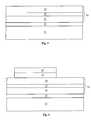
- FIG. 3shows a light-emitting structure 30 on a substrate 31 .
- a light-emitting structure 30is formed over the substrate 31 .
- the light-emitting structure 30includes a doped layer 35 , a multiple quantum well layer (MQW) 37 , and a doped layer 39 .
- the doped layers 35 and 39are oppositely doped semiconductor layers.
- the doped layer 35includes an n-type gallium nitride material
- the doped layer 39includes a p-type gallium nitride material.
- the doped layer 35may include a p-type gallium nitride material
- the doped layer 39may include an n-type gallium nitride material.
- the MQW layer 37 shown in FIG. 3includes alternating (or periodic) layers of active material, for example, gallium nitride and indium gallium nitride.
- the active material in an LEDis the primary source of light emission from an LED during operation.
- the MQW layer 37includes ten layers of gallium nitride and ten layers of indium gallium nitride, where an indium gallium nitride layer is formed on a gallium nitride layer, and another gallium nitride layer is formed on the indium gallium nitride layer, and so on and so forth.
- the number of layers of alternating layers and their thicknessesaffect the light emission efficiency.
- the thickness of the MQW layer 37may be, for example, about 100-2000 nm, about 1 ⁇ m, or about 1.5 ⁇ m.
- the doped layer 35 , the MQW layer 37 , and the doped layer 39are all formed by epitaxial growth processes.
- a first undoped layer 33usually gallium nitride (in some cases aluminum nitride) is grown on the substrate 31 .
- the first undoped layer 33is also referred to as a buffer layer 33 .
- the buffer layermay be about 500 nm to 5 ⁇ m, for example, about 1.5 ⁇ m or about 2 ⁇ m.
- the layers 35 , 37 , and 39are grown subsequently.
- the dopingmay be accomplished by adding impurities into a source gas during the epitaxial growth processes.
- a p-n junction(or a p-n diode) including the MQW layer 37 between the oppositely doped layers 35 and 39 is formed.
- an electrical voltageis applied between the doped layer 35 and the doped layer 39 , an electrical current flows through the light-emitting structure 30 and the MQW layer 37 emits radiation.
- the color of the light emitted by the MQW layer 37is associated with the wavelength of the emitted radiation, which may be tuned by varying the composition and structure of the materials that make up the MQW layer 37 . For example, a small increase in the concentration of indium in the indium gallium nitride layer is associated with a shift of the wavelength output toward longer wavelengths.
- the operation of forming a light-emitting structure 30may optionally include the formation of additional layers not shown in FIG. 3 .
- additional layersmay include an ohmic contact layer or other layers may be added on the doped layer 39 .
- These other layersmay include an indium tin oxide (ITO) layer, or another transparent conductive layer.
- ITOindium tin oxide
- the growth substrateis removed in many LED products, especially for high power LEDs.
- an interface between the growth substrate and the buffer layer 33is destroyed with electromagnetic radiation (for example, an excimer laser), which decomposes the buffer material at the interface.
- This interfacemay be an undoped gallium nitride layer.
- the growth substratefor example, sapphire, may be lifted off and removed.
- LLOlaser lift-off
- a laser beam generated by an excimer laseris injected from the sapphire side into the light-emitting structure to decompose the gallium nitride material at the interface between the substrate and the buffer layer to gallium atoms and nitrogen gas.
- the LLO methodis conventionally adopted for manufacturing LEDs when the substrate is removed.
- One particular feature of the LLO methodis that in many cases the sapphire removed may be recycled and used again as a growth substrate, saving material costs.
- the LLO methodis not suitable for many advanced LED applications and streamlined manufacturing as discovered by the inventors and disclosed herein.
- the LLO processgenerally uses high laser power density to decompose the gallium nitride at the buffer layer/substrate interface.
- the laser spotis usually set to the LED die size to ensure a clean lift-off.
- the growth substratesincrease in size, more and more LED dies are grown on the same substrate, which increases the LLO process time as the laser moves from spot to spot (die to die).
- the size of LED die suitable for the LLO processis also limited. As high-power LED applications using larger LED die are more widely used, the LLO process cannot keep up with the requirement to cleanly lift-off larger and larger dies.
- the laser spotoverlaps slightly at the edge.
- the high power densityis very destructive and crack formation at the edge of each overlapped laser spot can result.
- the laserwould damage exposed surface and sidewalls of the light-emitting structure. These cracks and damages can cause current leakage during operation.
- conventional LLO methodalso includes a backside sapphire polishing step to promote LLO process uniformity.
- the sapphire polishingreduces the likelihood that the sapphire may be recycled at the end of the process and adds manufacturing time and cost.
- the present disclosurepertains to a method of removing a growth substrate in multiple operations that does not include the use of a laser beam.
- the sapphire substrateis ground first to a first specified thickness using a single abrasive or multiple abrasives.
- the remaining sapphire substrateis removed by dry etching or wet etching.
- a first portion of the growth substrateis removed by grinding a back surface of the growth substrate.
- the grindingis tuned to remove sufficient growth substrate such that about 3 ⁇ m to about 20 ⁇ m about 10 ⁇ m, or about 5 ⁇ m remains.
- the grindingmay be accomplished in one operation or several operations depending on the abrasive used.
- the grinding toolis a wheel containing diamond particles of very fine dimension bonded with epoxy or wax. When the substrate is placed on the tool, the grinding wheel presses on the substrate backside and rotates in different directions. By the shear force exerted on the substrate, the hard diamond particles remove silicon from the substrate backside. Grinding operations to thin silicon substrates may additionally involve chemical etchants.
- Some commercially available tools for backside grinding of silicon substratesmay be configured for other substrates such as sapphire substrates.
- the abrasivemay be diamond particles with a size of 15 to 5 ⁇ m. The selection of the abrasive maximizes removal rate while maintaining control over grinding uniformity and rate.
- the grinding operationmay be about 30 minutes to 90 minutes.
- the first grinding operationmay remove less material than the single grinding operation in the other example.
- the first grinding operationmay remove sufficient growth substrate such that more than 6 ⁇ m remains.
- the wafermay be ground using large size particle abrasives to thin the wafers from about 430 to about 50 ⁇ m with grinding time of about 35 minutes.
- the about 50 ⁇ m thick waferis then ground again in a second stage grinding process to about 5 ⁇ m thickness using 6 ⁇ m diamond particle abrasives for about 20 minutes.
- the first operation abrasivemay be selected to maximize removal rate.
- the grindingcompletes the growth substrate removal down to the specified thickness.
- the first abrasivemay be harder and/or coarser than the second abrasive and other subsequent abrasives when more than two operations are used.
- the initial sapphire backside surface conditionis not relevant for the grinding process. Thus no surface preparation is performed before the grinding operation, unlike the LLO process, which requires the surface to be polished.
- the etchingis dry etching using inductively coupled plasma (ICP).
- ICPinductively coupled plasma
- the ICP etchmay involve inert species such nitrogen, argon, krypton, xenon, oxygen, and other known gases.
- the ICP etchmay also involve reactive ion species such as fluorine containing etchants (i.e., CF 4 , CHF 3 , SF 6 , C 4 F 8 , C 4 F 10 , C x F 2x+2 , CCl 3 F, CCl 2 F 2 , CF 3 Cl, C 2 ClF 5 ), chlorine containing etchants (i.e., BCl 3 , BCl 3 +Cl 2 , CCl 4 , CCl 4 +Cl 2 , BCl 3 +Cl 2 , CCl 3 F, CCl 2 F 2 , CF 3 Cl, C 2 ClF 5 ), bromine containing etchants (i.e., HBr), and other halogen containing etchants.
- a high-density plasmais produced in situ in the process chamber.
- the plasma etching operationmay be conducted at a substrate temperature of less than about 150° C., preferably at about room temperature.
- a biasmay be applied
- the plasma dry etchingmay be performed with other plasma generation methods, including capacitively coupled plasma (CCP), magnetron plasma, electron cyclotron resonance (ECR), or microwave.
- CCPcapacitively coupled plasma
- ECRelectron cyclotron resonance
- the plasmamay be generated in situ or remotely.
- the plasmamay have high ion density.
- the etchingis wet etching.
- the wet etchingmay involve sulfuric acid, phosphoric acid, or a combination of these etchants.
- the substrateis immersed in an etchant solution for a time until sufficient amount of the growth substrate is removed.
- the sulfuric acidmay be H 2 SO 4
- the phosphoric acidmay be H 3 PO 4 .
- the etchant solutionmay also include amounts of CH 3 COOH, HNO 3 , water, and other commonly used etchant components.
- the etchant solutionmay be a 3H 2 SO 4 : 1H 3 PO 4 mixture with CH 3 COOH, HNO 3 , and water.
- the etchant solutionis heated to greater than 100° C., over 200° C., over 300° C., or over 400° C.
- the wet etchingmay occur in a chamber under pressure, for example, at above 1 atmosphere, or above 1.5 atmospheres, or above 2 atmospheres.
- One typical wet etching solutionis 3H 2 SO 4 :1H 3 PO 4 mixture with CH 3 COOH, HNO 3 , and water with temperature of 300° C. under atmospheric pressure.
- One skilled in the artwould be able to design a wet etching process to achieve a suitable etch rate and selectivity. Because the entire partially fabricated LED is exposed to the etchant solution, portions of the device may be protected first with a passivation layer.
- the passivation layeris selected to have a much lower etch rate than the growth substrate for the etching process.
- the passivation layermust also adequately cover the exposed light-emitting mesa structure sidewall, in other words, be sufficiently conformal so no unwanted etching occurs on the device itself.
- FIG. 2is a process flow diagram of an example flow 12 in accordance with the broader flow 11 and various embodiments of the present disclosure.
- Example flow 12illustrates one process for making an LED package with an LED with its substrate removed in accordance with the method embodiments of the present disclosure.
- Other types of LED packages made with processes other than example flow 12may also be suitable for the LED with its substrate removed in accordance with the method embodiments of the present disclosure.
- An exampleincludes a flipped LED package attached to a package substrate by solder bumps.
- a growth substratesuch as a sapphire substrate is provided.
- a light-emitting structureis formed on the substrate.
- a contact metal layeris optionally formed on the light-emitting structure and a bonding metal layer is formed over the contact metal layer, in operation 16 .
- a reflecting metal layermay be disposed between the contact metal layer and the bonding metal layer.
- the structureis then etched using a scribe pattern to form light-emitting mesa structures in operation 17 .
- a passivation layeris deposited in operation 18 to protect the mesa structure, especially exposed mesa sidewall portions.
- a first portion of the growth substrateis removed by grinding a back surface of the substrate. As discussed above, the grinding operation may include one or more operations using different abrasives.
- a remaining portion of the growth substrateis removed by etching, either plasma etching, wet etching, or a combination of both.
- FIGS. 3 to 15illustrate example intermediate structures of the process flow of FIG. 2 .
- FIG. 3depict forming the light-emitting structure 30 as disclosed above.
- FIG. 4shows a contact metal layer 41 and optionally a reflecting metal layer 43 formed on the light-emitting structure 30 .
- the contact metal layer 41is a metal, which may be nickel, an alloy of nickel such as nickel/gold, or some metallic alloy such as chromium/platinum/gold, titanium/aluminum/titanium/gold, or other similar alloys.
- the contact metal layer 41is a nickel/silver alloy.
- the contact metal layer 41adheres well to the top layer of the light-emitting structure 30 and the reflecting metal layer 43 .
- a light reflecting layer 43may be a metal, such as aluminum, copper, titanium, silver, gold, alloys of these such as titanium/platinum/gold, or combinations thereof. Particularly, silver and aluminum are known to be good reflectors of blue light.
- the light-reflecting layermay be formed by a physical vapor deposition (PVD) process or a chemical vapor deposition (CVD) or other deposition processes. Together, the contact metal layer 41 and a reflecting metal layer 43 may have a thickness of about 300 nm.
- the contact metal layer 41 and the optional reflecting metal layer 43are deposited using the same pattern using a PVD process or a CVD process or other deposition processes.
- the layersmay be deposited using different techniques. For example, layer 43 may be deposited using electrochemical plating while layer 41 may be deposited using PVD.
- FIG. 5shows a photoresist pattern 45 on and around the metal layers 41 and 43 .
- a photoresist pattern 45is deposited, exposed, and developed on the workpiece. The pattern defines an area around the metal layers 41 and 43 .
- FIG. 6shows the streets 47 , or grooves, etched to the light-emitting structure 30 of FIG. 5 according to the photoresist pattern 45 .
- the streets 47separate individual light-emitting mesa structures. While the streets are shown to have high aspect ratios, the drawings are not to scale and in reality the streets may be much wider than they appear.
- the mesa structuremay be a total of several microns high and hundreds or thousands of microns wide. The street width may be more than 50 microns wide.
- the etch stopsat about the interface between the buffer layer 33 and the growth substrate 31 . In various embodiments, the process may include a slight overetch and the substrate 31 may act as an etch stop layer.
- the light-emitting mesa structure etchmay be a dry etch or a wet etch.
- dry etchingan inductively coupled plasma may be used with argon or nitrogen plasma.
- wet etchingHCl, HF, HI, H 2 SO 4 , H 2 PO 4 , H 3 PO 4 , or a combination of these sequentially may be used.
- Some wet etchantsrequire a higher temperature to reach an effective etch rate, such as phosphoric acid with etching temperature of about 50° C. to about 100° C.
- the photoresist pattern 45is removed, as shown in FIG. 7A .
- a passivation layer 51is then formed on the top and sidewalls of the light-emitting mesa structure and on the substrate in the streets 47 as shown in FIG. 7B .
- the passivation layer 51passivates the exposed surface against unwanted reactions caused by materials used in subsequent processing. Particularly, the passivation layer 51 protects the exposed sidewalls of the light-emitting mesa structures from subsequent processing operations of photoresist removal, backside (growth substrate) grinding, and backside etching.
- the passivation layer 51is selected to have a much lower etch rate than the growth substrate for the etching process.
- the passivation layer 51must also adequately cover the exposed light-emitting mesa structure sidewall, in other words, be sufficiently conformal. Depending on the passivation layer material, this consideration may limit the types of processes that can be used to deposit the material.
- the passivation layer 51may be a silicon oxide, silicon nitride, silicon oxynitride, silicon carbide, carbon-doped silicon oxide, carbon-doped silicon nitride, or other known non-conductive passivation material.
- a silicon oxidemay be deposited using plasma-enhanced chemical vapor deposition (PECVD) process.
- PECVDplasma-enhanced chemical vapor deposition
- PECVDplasma-enhanced chemical vapor deposition
- PECVDplasma-enhanced chemical vapor deposition
- the passivation layer 51may deposit and form different thicknesses at the sidewall and on the field, or horizontal, regions as shown.
- the passivation layer 51 as measured from the sidewall into the light-emitting mesa structuresmay be about 600 angstroms, or at least 100 angstroms, and may be as much as 1000 nm, depending on the type of plasma and bias used.
- a portion of the passivation layer 51 on top of the light-emitting mesa structureis then removed by patterning and etching, as shown in FIG. 8A .
- the passivation layer 51 above layer 39is removed to expose contact metal layer 41 and reflecting metal layer 43 .
- a photoresist patternis formed over the passivation layer 51 that protects a portion of the passivation layer 51 in the street and on the sidewalls of the light-emitting mesa structures.
- the unprotected portion of the passivation layer 51 over the light-emitting mesa structures over and around the metal layers 41 and 43is then etched away by dry etching or wet etching.
- FIG. 8Bshows the addition of bonding metal layer 53 to the contact metal layer 41 and reflecting metal layer 43 .
- the bonding metal materialmay be a soft metal suitable for bonding with an adhesion metal layer on a bonding substrate.
- the bonding metalmay be gold or a gold/tin alloy.
- the photoresist patternsneed not be removed or stripped for the bonding metal material deposition.
- the bonding metalmay be deposited using PVD, CVD or other deposition process including electrodeposition or electroless deposition.
- the light-emitting mesa structures and the growth substrateare flipped over and bonded to a bonding substrate as shown in FIG. 9 .
- the bonding metal layer 53is bonded to an adhesion metal layer 57 on a substrate 59 .
- Substrate 59is usually a silicon substrate, but may also be metal or ceramic. A suitable substrate would have a high thermal conductivity, such as silicon or copper.
- the adhesion metal layermay be made of gold, tin, or an alloy of these.
- the bonding metal layer 53 and the adhesion metal layer 57may be bonded via eutectic bonding or metal bonding.
- the bonding metal layermay be a gold/tin alloy and the adhesion metal layer may be made of gold.
- both metal layers 53 and 57may be gold.
- FIG. 10shows a thinned growth substrate 55 after one or more grinding operations.
- FIG. 11shows the light-emitting mesa structures bonded to the bonding substrate 59 after the growth substrate is completely removed.
- the thinned growth substrate 55is removed by dry etching or wet etching.
- the individual light-emitting mesa structureis referred to as an LED die. Each LED die is capable of generating light independently from one another.
- FIG. 12shows the substrate mounted LED dies having a portion of the buffer layer 33 removed.
- a photoresist patternmay be first applied to protect portions of the structure from the removal process.
- the photoresist patternmay be applied to the edges of the LED die, the passivation layer surface 51 , and surfaces of the metal layers 53 and 57 .
- a dry etch processmay be employed, for example, inductively coupled plasma process to remove portion of the buffer layer 33 . Note that although FIG. 12 shows the edge of buffer layer 33 remaining on the LED die, it is not necessary.
- the figures and textdescribes protecting the edges using a photoresist so as to not to remove the passivation layer 51 .
- ICPwith a bias to perform physical etching using heavier molecules, such as argon, krypton, or xenon, may be used.
- the exposed surface of the first doped layer 35is then treated to obtain a rough surface 61 and form metal contacts 63 and 64 at the surface.
- the surfaceis patterned first to protect areas on which the metal contacts 63 would form and then treated with plasma to form a rough surface.
- a plasma etch using chemical etchants such as chlorineis used to etch the surface along the gallium nitride crystal lattice structure, forming a rough surface having small triangular shapes.
- the roughened surfacemay then be patterned for the contact metal deposition.
- the contact metalis deposited to form an interconnect pattern on the die surface with thin contacts 63 with a number of contact pads 64 . Such an interconnect structure spreads the current throughout the surface.
- FIG. 14An example contact pattern is shown in FIG. 14 .
- the contact pads 64are connected by thin contact structures 63 .
- the thin contacts 63may be about 20 to about 30 ⁇ m wide, while the contact pads may be about 50 to 80 ⁇ m wide. Note that while a photoresist patterning step may be skipped by forming the contacts on a roughened surface or by subjecting the contact metal to plasma etching, the contact resistance may correspondingly increase.
- An additional passivation layer material 65may be also deposited to protect the exposed bonding metal layer 53 sidewalls.
- the additional passivation layer material 65may be of the same composition as passivation layer 51 or different materials.
- the passivation layer material 65may be deposited directly over the passivation layer 51 .
- An LEDis essentially formed after the contact structure 63 and 64 are completed.
- the LEDmay be tested and binned while mounted on the bonding substrate before dicing.
- electrodesare moved across the substrate from LED die to LED die. The light output at each LED die is measured.
- any defect in the LED die causing light output that is below a minimum specificationcan be marked and removed from subsequent processing.
- the discardmay include more material and manufacturing costs such as packaging, lens molding, and phosphor coating. Such early defective product removal saves manufacturing time and material costs.
- LED die with light outputs that meet the minimum specificationare categorized into different bins for further manufacturing of products having different specifications.
- FIG. 15shows an example of testing and binning substrate mounted LED dies.
- Temporary contactsare formed in the streets between the LED dies for testing and binning the individual dies as shown.
- a portion of the passivation layer material 65is patterned and opened to allow the temporary contact 67 to be deposited. This operation may occur concurrently with deposition of the contact structure of 63 and 64 .
- a currentis conducted across the LED die and the resulting light output measured.
- a pair of electrode probes 69 and 71contact the contact 64 and the temporary contact 67 .
- the testingmay include measuring different output in response of different current inputs. LED dies that respond similarly are binned together.
- one temporary contactmay be used for testing several adjacent LED dies when the structures are tested one at a time and have the same geometry.
- each LED dieAfter the LED dies are binned, they can be diced or separated into individual LEDs.
- the dicing processmay be a non-etching process where a cutting device, such as a laser beam or a saw blade, is used to physically separate the LED dies. After being diced, each LED die is capable of generating light and is physically and electrically independent from one another.
Landscapes
- Led Devices (AREA)
Abstract
Description
Claims (20)
Priority Applications (4)
| Application Number | Priority Date | Filing Date | Title |
|---|---|---|---|
| US12/881,457US8563334B2 (en) | 2010-09-14 | 2010-09-14 | Method to remove sapphire substrate |
| TW100131217ATWI506810B (en) | 2010-09-14 | 2011-08-31 | Method for manufacturing light emitting diode |
| CN201610104400.6ACN105845787A (en) | 2010-09-14 | 2011-09-13 | Method for manufacturing semiconductor element |
| CN201110276404.XACN102403415B (en) | 2010-09-14 | 2011-09-13 | Manufacturing method of light emitting diode |
Applications Claiming Priority (1)
| Application Number | Priority Date | Filing Date | Title |
|---|---|---|---|
| US12/881,457US8563334B2 (en) | 2010-09-14 | 2010-09-14 | Method to remove sapphire substrate |
Publications (2)
| Publication Number | Publication Date |
|---|---|
| US20120064642A1 US20120064642A1 (en) | 2012-03-15 |
| US8563334B2true US8563334B2 (en) | 2013-10-22 |
Family
ID=45807100
Family Applications (1)
| Application Number | Title | Priority Date | Filing Date |
|---|---|---|---|
| US12/881,457ActiveUS8563334B2 (en) | 2010-09-14 | 2010-09-14 | Method to remove sapphire substrate |
Country Status (3)
| Country | Link |
|---|---|
| US (1) | US8563334B2 (en) |
| CN (2) | CN105845787A (en) |
| TW (1) | TWI506810B (en) |
Cited By (1)
| Publication number | Priority date | Publication date | Assignee | Title |
|---|---|---|---|---|
| US20210044088A1 (en)* | 2018-03-19 | 2021-02-11 | Sony Corporation | Semiconductor light-emitting device and method of manufacturing semiconductor light-emitting device |
Families Citing this family (73)
| Publication number | Priority date | Publication date | Assignee | Title |
|---|---|---|---|---|
| KR101659953B1 (en)* | 2010-03-30 | 2016-09-27 | 삼성디스플레이 주식회사 | Organic light emitting display apparatus and the manufacturing method thereof |
| DE102011116232B4 (en)* | 2011-10-17 | 2020-04-09 | Osram Opto Semiconductors Gmbh | Optoelectronic semiconductor chip and method for its production |
| US8794501B2 (en) | 2011-11-18 | 2014-08-05 | LuxVue Technology Corporation | Method of transferring a light emitting diode |
| US8518204B2 (en) | 2011-11-18 | 2013-08-27 | LuxVue Technology Corporation | Method of fabricating and transferring a micro device and an array of micro devices utilizing an intermediate electrically conductive bonding layer |
| US8349116B1 (en) | 2011-11-18 | 2013-01-08 | LuxVue Technology Corporation | Micro device transfer head heater assembly and method of transferring a micro device |
| US8573469B2 (en)* | 2011-11-18 | 2013-11-05 | LuxVue Technology Corporation | Method of forming a micro LED structure and array of micro LED structures with an electrically insulating layer |
| US8333860B1 (en) | 2011-11-18 | 2012-12-18 | LuxVue Technology Corporation | Method of transferring a micro device |
| US9773750B2 (en) | 2012-02-09 | 2017-09-26 | Apple Inc. | Method of transferring and bonding an array of micro devices |
| US9076923B2 (en)* | 2012-02-13 | 2015-07-07 | Epistar Corporation | Light-emitting device manufacturing method |
| US9548332B2 (en) | 2012-04-27 | 2017-01-17 | Apple Inc. | Method of forming a micro LED device with self-aligned metallization stack |
| US9105492B2 (en) | 2012-05-08 | 2015-08-11 | LuxVue Technology Corporation | Compliant micro device transfer head |
| US8415771B1 (en) | 2012-05-25 | 2013-04-09 | LuxVue Technology Corporation | Micro device transfer head with silicon electrode |
| US9034754B2 (en) | 2012-05-25 | 2015-05-19 | LuxVue Technology Corporation | Method of forming a micro device transfer head with silicon electrode |
| TWI488336B (en)* | 2012-06-07 | 2015-06-11 | Lextar Electronics Corp | Light-emitting diode and manufacturing method thereof |
| US8415767B1 (en) | 2012-07-06 | 2013-04-09 | LuxVue Technology Corporation | Compliant bipolar micro device transfer head with silicon electrodes |
| US8569115B1 (en) | 2012-07-06 | 2013-10-29 | LuxVue Technology Corporation | Method of forming a compliant bipolar micro device transfer head with silicon electrodes |
| US8415768B1 (en) | 2012-07-06 | 2013-04-09 | LuxVue Technology Corporation | Compliant monopolar micro device transfer head with silicon electrode |
| US8791530B2 (en) | 2012-09-06 | 2014-07-29 | LuxVue Technology Corporation | Compliant micro device transfer head with integrated electrode leads |
| US9162880B2 (en) | 2012-09-07 | 2015-10-20 | LuxVue Technology Corporation | Mass transfer tool |
| US8835940B2 (en) | 2012-09-24 | 2014-09-16 | LuxVue Technology Corporation | Micro device stabilization post |
| US8941215B2 (en) | 2012-09-24 | 2015-01-27 | LuxVue Technology Corporation | Micro device stabilization post |
| TW201414012A (en)* | 2012-09-26 | 2014-04-01 | Chi Mei Lighting Tech Corp | Light emitting device and manufacturing method thereof |
| US9558721B2 (en) | 2012-10-15 | 2017-01-31 | Apple Inc. | Content-based adaptive refresh schemes for low-power displays |
| KR101997021B1 (en)* | 2012-11-23 | 2019-07-08 | 서울바이오시스 주식회사 | Method for Fabricating Vertical Type Light Emitting Device |
| US9159700B2 (en) | 2012-12-10 | 2015-10-13 | LuxVue Technology Corporation | Active matrix emissive micro LED display |
| US9255001B2 (en) | 2012-12-10 | 2016-02-09 | LuxVue Technology Corporation | Micro device transfer head array with metal electrodes |
| US9029880B2 (en) | 2012-12-10 | 2015-05-12 | LuxVue Technology Corporation | Active matrix display panel with ground tie lines |
| US9236815B2 (en) | 2012-12-10 | 2016-01-12 | LuxVue Technology Corporation | Compliant micro device transfer head array with metal electrodes |
| US9178123B2 (en) | 2012-12-10 | 2015-11-03 | LuxVue Technology Corporation | Light emitting device reflective bank structure |
| US9166114B2 (en) | 2012-12-11 | 2015-10-20 | LuxVue Technology Corporation | Stabilization structure including sacrificial release layer and staging cavity |
| US9105714B2 (en) | 2012-12-11 | 2015-08-11 | LuxVue Technology Corporation | Stabilization structure including sacrificial release layer and staging bollards |
| US9314930B2 (en) | 2012-12-14 | 2016-04-19 | LuxVue Technology Corporation | Micro pick up array with integrated pivot mount |
| US9391042B2 (en) | 2012-12-14 | 2016-07-12 | Apple Inc. | Micro device transfer system with pivot mount |
| US9153171B2 (en) | 2012-12-17 | 2015-10-06 | LuxVue Technology Corporation | Smart pixel lighting and display microcontroller |
| US9095980B2 (en) | 2013-02-25 | 2015-08-04 | LuxVue Technology Corporation | Micro pick up array mount with integrated displacement sensor |
| US9308649B2 (en) | 2013-02-25 | 2016-04-12 | LuxVue Techonology Corporation | Mass transfer tool manipulator assembly |
| US8791474B1 (en) | 2013-03-15 | 2014-07-29 | LuxVue Technology Corporation | Light emitting diode display with redundancy scheme |
| US9252375B2 (en) | 2013-03-15 | 2016-02-02 | LuxVue Technology Corporation | Method of fabricating a light emitting diode display with integrated defect detection test |
| CN108054270B (en)* | 2013-04-27 | 2019-11-05 | 新世纪光电股份有限公司 | LED structure |
| US9217541B2 (en) | 2013-05-14 | 2015-12-22 | LuxVue Technology Corporation | Stabilization structure including shear release posts |
| US9484504B2 (en)* | 2013-05-14 | 2016-11-01 | Apple Inc. | Micro LED with wavelength conversion layer |
| US9136161B2 (en) | 2013-06-04 | 2015-09-15 | LuxVue Technology Corporation | Micro pick up array with compliant contact |
| EP3008553B1 (en) | 2013-06-12 | 2023-06-07 | Rohinni, Inc. | Keyboard backlighting with deposited light-generating sources |
| US8987765B2 (en) | 2013-06-17 | 2015-03-24 | LuxVue Technology Corporation | Reflective bank structure and method for integrating a light emitting device |
| US8928021B1 (en) | 2013-06-18 | 2015-01-06 | LuxVue Technology Corporation | LED light pipe |
| US9111464B2 (en) | 2013-06-18 | 2015-08-18 | LuxVue Technology Corporation | LED display with wavelength conversion layer |
| US9035279B2 (en) | 2013-07-08 | 2015-05-19 | LuxVue Technology Corporation | Micro device with stabilization post |
| US9296111B2 (en) | 2013-07-22 | 2016-03-29 | LuxVue Technology Corporation | Micro pick up array alignment encoder |
| US9087764B2 (en) | 2013-07-26 | 2015-07-21 | LuxVue Technology Corporation | Adhesive wafer bonding with controlled thickness variation |
| US9153548B2 (en) | 2013-09-16 | 2015-10-06 | Lux Vue Technology Corporation | Adhesive wafer bonding with sacrificial spacers for controlled thickness variation |
| US9367094B2 (en) | 2013-12-17 | 2016-06-14 | Apple Inc. | Display module and system applications |
| US9768345B2 (en) | 2013-12-20 | 2017-09-19 | Apple Inc. | LED with current injection confinement trench |
| US9450147B2 (en) | 2013-12-27 | 2016-09-20 | Apple Inc. | LED with internally confined current injection area |
| US9583466B2 (en) | 2013-12-27 | 2017-02-28 | Apple Inc. | Etch removal of current distribution layer for LED current confinement |
| US9542638B2 (en) | 2014-02-18 | 2017-01-10 | Apple Inc. | RFID tag and micro chip integration design |
| US9583533B2 (en) | 2014-03-13 | 2017-02-28 | Apple Inc. | LED device with embedded nanowire LEDs |
| US9522468B2 (en) | 2014-05-08 | 2016-12-20 | Apple Inc. | Mass transfer tool manipulator assembly with remote center of compliance |
| US9318475B2 (en) | 2014-05-15 | 2016-04-19 | LuxVue Technology Corporation | Flexible display and method of formation with sacrificial release layer |
| US9741286B2 (en) | 2014-06-03 | 2017-08-22 | Apple Inc. | Interactive display panel with emitting and sensing diodes |
| US9624100B2 (en) | 2014-06-12 | 2017-04-18 | Apple Inc. | Micro pick up array pivot mount with integrated strain sensing elements |
| US9425151B2 (en) | 2014-06-17 | 2016-08-23 | Apple Inc. | Compliant electrostatic transfer head with spring support layer |
| US9570002B2 (en) | 2014-06-17 | 2017-02-14 | Apple Inc. | Interactive display panel with IR diodes |
| US9828244B2 (en) | 2014-09-30 | 2017-11-28 | Apple Inc. | Compliant electrostatic transfer head with defined cavity |
| US9705432B2 (en) | 2014-09-30 | 2017-07-11 | Apple Inc. | Micro pick up array pivot mount design for strain amplification |
| US9478583B2 (en) | 2014-12-08 | 2016-10-25 | Apple Inc. | Wearable display having an array of LEDs on a conformable silicon substrate |
| US20160351548A1 (en)* | 2015-05-28 | 2016-12-01 | Mikro Mesa Technology Co., Ltd. | Light emitting diode display device and manufacturing method thereof |
| JP6959697B2 (en) | 2016-01-15 | 2021-11-05 | ロヒンニ リミテッド ライアビリティ カンパニー | Devices and methods that are backlit through a cover on the device |
| CN107623060B (en)* | 2017-09-06 | 2019-10-25 | 佛山市国星半导体技术有限公司 | A kind of manufacturing method of removing DBR film layer |
| CN107581841B (en)* | 2017-10-19 | 2023-07-18 | 浙江朵纳家居股份有限公司 | LED mirror base and preparation method thereof |
| TWI846193B (en)* | 2017-12-07 | 2024-06-21 | 晶元光電股份有限公司 | Semiconductor device |
| TWI759441B (en)* | 2018-03-07 | 2022-04-01 | 優顯科技股份有限公司 | Manufacturing method of photovoltaic semiconductor device |
| CN108899272A (en)* | 2018-07-06 | 2018-11-27 | 德淮半导体有限公司 | Method for manufacturing semiconductor device |
| TWI806275B (en)* | 2021-12-08 | 2023-06-21 | 欣興電子股份有限公司 | Light-emitting diode package and manufacturing method thereof |
Citations (11)
| Publication number | Priority date | Publication date | Assignee | Title |
|---|---|---|---|---|
| US4180422A (en)* | 1969-02-03 | 1979-12-25 | Raytheon Company | Method of making semiconductor diodes |
| US20070170933A1 (en)* | 2006-01-23 | 2007-07-26 | Maxmile Technologies, Llc | Method and Apparatus for Nondestructively Evaluating Light-Emitting Materials |
| US20090020772A1 (en)* | 2007-07-19 | 2009-01-22 | Ching-Hua Chiu | Light-emitting device and method for making the same |
| US20090278233A1 (en)* | 2007-07-26 | 2009-11-12 | Pinnington Thomas Henry | Bonded intermediate substrate and method of making same |
| US20100003904A1 (en)* | 2000-11-17 | 2010-01-07 | Duescher Wayne O | High speed flat lapping platen, raised islands and abrasive beads |
| US20100015787A1 (en)* | 2008-07-21 | 2010-01-21 | Chen-Hua Yu | Realizing N-Face III-Nitride Semiconductors by Nitridation Treatment |
| US20100013060A1 (en)* | 2008-06-22 | 2010-01-21 | Taiwan Semiconductor Manufacturing Company, Ltd. | Method of forming a conductive trench in a silicon wafer and silicon wafer comprising such trench |
| US20100129991A1 (en)* | 2007-03-02 | 2010-05-27 | Mitsubishi Electric Corporation | Nitride semiconductor device having a silicon-containing layer and manufacturing method thereof |
| US20100171125A1 (en)* | 2002-06-26 | 2010-07-08 | Yoo Myung Cheol | Thin film light emitting diode |
| US20100314605A1 (en)* | 2006-10-18 | 2010-12-16 | Asif Khan | Vertical deep ultraviolet light emitting diodes |
| US20110001120A1 (en)* | 2008-03-25 | 2011-01-06 | Lattice Power (Jiangxi) Corporation | Semiconductor light-emitting device with double-sided passivation |
Family Cites Families (7)
| Publication number | Priority date | Publication date | Assignee | Title |
|---|---|---|---|---|
| WO2003065464A1 (en)* | 2002-01-28 | 2003-08-07 | Nichia Corporation | Nitride semiconductor device having support substrate and its manufacturing method |
| US7344903B2 (en)* | 2003-09-17 | 2008-03-18 | Luminus Devices, Inc. | Light emitting device processes |
| TWI234298B (en)* | 2003-11-18 | 2005-06-11 | Itswell Co Ltd | Semiconductor light emitting diode and method for manufacturing the same |
| JP2008306021A (en)* | 2007-06-08 | 2008-12-18 | Ushio Inc | LED chip manufacturing method |
| CN101345277B (en)* | 2007-07-12 | 2011-08-24 | 台达电子工业股份有限公司 | Manufacturing method of light emitting diode device |
| US8048807B2 (en)* | 2008-09-05 | 2011-11-01 | Taiwan Semiconductor Manufacturing Company, Ltd. | Method and apparatus for thinning a substrate |
| CN101494267B (en)* | 2008-11-24 | 2010-09-29 | 厦门市三安光电科技有限公司 | Preparation method for gallium nitride base light-emitting device based on substrate desquamation |
- 2010
- 2010-09-14USUS12/881,457patent/US8563334B2/enactiveActive
- 2011
- 2011-08-31TWTW100131217Apatent/TWI506810B/enactive
- 2011-09-13CNCN201610104400.6Apatent/CN105845787A/enactivePending
- 2011-09-13CNCN201110276404.XApatent/CN102403415B/enactiveActive
Patent Citations (12)
| Publication number | Priority date | Publication date | Assignee | Title |
|---|---|---|---|---|
| US4180422A (en)* | 1969-02-03 | 1979-12-25 | Raytheon Company | Method of making semiconductor diodes |
| US20100003904A1 (en)* | 2000-11-17 | 2010-01-07 | Duescher Wayne O | High speed flat lapping platen, raised islands and abrasive beads |
| US20100171125A1 (en)* | 2002-06-26 | 2010-07-08 | Yoo Myung Cheol | Thin film light emitting diode |
| US20070170933A1 (en)* | 2006-01-23 | 2007-07-26 | Maxmile Technologies, Llc | Method and Apparatus for Nondestructively Evaluating Light-Emitting Materials |
| US20100314605A1 (en)* | 2006-10-18 | 2010-12-16 | Asif Khan | Vertical deep ultraviolet light emitting diodes |
| US20100129991A1 (en)* | 2007-03-02 | 2010-05-27 | Mitsubishi Electric Corporation | Nitride semiconductor device having a silicon-containing layer and manufacturing method thereof |
| US20090020772A1 (en)* | 2007-07-19 | 2009-01-22 | Ching-Hua Chiu | Light-emitting device and method for making the same |
| US20090278233A1 (en)* | 2007-07-26 | 2009-11-12 | Pinnington Thomas Henry | Bonded intermediate substrate and method of making same |
| US20110001120A1 (en)* | 2008-03-25 | 2011-01-06 | Lattice Power (Jiangxi) Corporation | Semiconductor light-emitting device with double-sided passivation |
| US20100013060A1 (en)* | 2008-06-22 | 2010-01-21 | Taiwan Semiconductor Manufacturing Company, Ltd. | Method of forming a conductive trench in a silicon wafer and silicon wafer comprising such trench |
| US20100015787A1 (en)* | 2008-07-21 | 2010-01-21 | Chen-Hua Yu | Realizing N-Face III-Nitride Semiconductors by Nitridation Treatment |
| US7875534B2 (en)* | 2008-07-21 | 2011-01-25 | Taiwan Semiconductor Manufacturing Company, Ltd. | Realizing N-face III-nitride semiconductors by nitridation treatment |
Non-Patent Citations (1)
| Title |
|---|
| Luxeon(R) Product Binning and Labeling, Application Brief AB21, pp. 1-8 (2007). Cf. Other Publications of US 7,838,878 by Greisen.* |
Cited By (2)
| Publication number | Priority date | Publication date | Assignee | Title |
|---|---|---|---|---|
| US20210044088A1 (en)* | 2018-03-19 | 2021-02-11 | Sony Corporation | Semiconductor light-emitting device and method of manufacturing semiconductor light-emitting device |
| US11929591B2 (en)* | 2018-03-19 | 2024-03-12 | Sony Corporation | Semiconductor light-emitting device and method of manufacturing semiconductor light-emitting device |
Also Published As
| Publication number | Publication date |
|---|---|
| CN102403415A (en) | 2012-04-04 |
| CN102403415B (en) | 2016-03-23 |
| TWI506810B (en) | 2015-11-01 |
| CN105845787A (en) | 2016-08-10 |
| US20120064642A1 (en) | 2012-03-15 |
| TW201214747A (en) | 2012-04-01 |
Similar Documents
| Publication | Publication Date | Title |
|---|---|---|
| US8563334B2 (en) | Method to remove sapphire substrate | |
| US9882084B2 (en) | Vertical structure LEDs | |
| US20160247973A1 (en) | Method of light emitting diode sidewall passivation | |
| US6818532B2 (en) | Method of etching substrates | |
| US20050104081A1 (en) | Semiconductor light emitting diode and method for manufacturing the same | |
| CN103187491B (en) | Manufacturing method of wafer-level light-emitting diode structure and light-emitting diode chip | |
| US20150108424A1 (en) | Method to Remove Sapphire Substrate | |
| CN103066168A (en) | Light emitting diode and method for manufacturing the same | |
| KR100629210B1 (en) | Vertical Light Emitting Diode and Manufacturing Method Thereof |
Legal Events
| Date | Code | Title | Description |
|---|---|---|---|
| AS | Assignment | Owner name:TAIWAN SEMICONDUCTOR MANUFACTURING COMPANY, LTD., Free format text:ASSIGNMENT OF ASSIGNORS INTEREST;ASSIGNORS:HUANG, HUNG-WEN;HSIA, HSING-KUO;CHIU, CHING-HUA;REEL/FRAME:024983/0684 Effective date:20100907 | |
| AS | Assignment | Owner name:TSMC SOLID STATE LIGHTING LTD, TAIWAN Free format text:ASSIGNMENT OF ASSIGNORS INTEREST;ASSIGNOR:TAIWAN SEMICONDUCTOR MANUFACTURING COMPANY LTD.;REEL/FRAME:028033/0633 Effective date:20120301 | |
| STCF | Information on status: patent grant | Free format text:PATENTED CASE | |
| AS | Assignment | Owner name:CHIP STAR LTD., TAIWAN Free format text:CHANGE OF NAME;ASSIGNOR:TSMC SOLID STATE LIGHTING LTD.;REEL/FRAME:037208/0415 Effective date:20150402 Owner name:EPISTAR CORPORATION, TAIWAN Free format text:MERGER;ASSIGNOR:CHIP STAR LTD.;REEL/FRAME:037457/0534 Effective date:20150715 | |
| FPAY | Fee payment | Year of fee payment:4 | |
| MAFP | Maintenance fee payment | Free format text:PAYMENT OF MAINTENANCE FEE, 8TH YEAR, LARGE ENTITY (ORIGINAL EVENT CODE: M1552); ENTITY STATUS OF PATENT OWNER: LARGE ENTITY Year of fee payment:8 | |
| MAFP | Maintenance fee payment | Free format text:PAYMENT OF MAINTENANCE FEE, 12TH YEAR, LARGE ENTITY (ORIGINAL EVENT CODE: M1553); ENTITY STATUS OF PATENT OWNER: LARGE ENTITY Year of fee payment:12 |